US8461672B2 - Reconstituted wafer stack packaging with after-applied pad extensions - Google Patents
Reconstituted wafer stack packaging with after-applied pad extensionsDownload PDFInfo
- Publication number
- US8461672B2 US8461672B2US12/670,952US67095208AUS8461672B2US 8461672 B2US8461672 B2US 8461672B2US 67095208 AUS67095208 AUS 67095208AUS 8461672 B2US8461672 B2US 8461672B2
- Authority
- US
- United States
- Prior art keywords
- microelectronic
- microelectronic elements
- subassembly
- edges
- elements
- Prior art date
- Legal status (The legal status is an assumption and is not a legal conclusion. Google has not performed a legal analysis and makes no representation as to the accuracy of the status listed.)
- Expired - Fee Related, expires
Links
Images


Classifications
- H—ELECTRICITY
- H01—ELECTRIC ELEMENTS
- H01L—SEMICONDUCTOR DEVICES NOT COVERED BY CLASS H10
- H01L21/00—Processes or apparatus adapted for the manufacture or treatment of semiconductor or solid state devices or of parts thereof
- H01L21/02—Manufacture or treatment of semiconductor devices or of parts thereof
- H01L21/04—Manufacture or treatment of semiconductor devices or of parts thereof the devices having potential barriers, e.g. a PN junction, depletion layer or carrier concentration layer
- H01L21/50—Assembly of semiconductor devices using processes or apparatus not provided for in a single one of the groups H01L21/18 - H01L21/326 or H10D48/04 - H10D48/07 e.g. sealing of a cap to a base of a container
- H—ELECTRICITY
- H01—ELECTRIC ELEMENTS
- H01L—SEMICONDUCTOR DEVICES NOT COVERED BY CLASS H10
- H01L24/00—Arrangements for connecting or disconnecting semiconductor or solid-state bodies; Methods or apparatus related thereto
- H01L24/93—Batch processes
- H01L24/95—Batch processes at chip-level, i.e. with connecting carried out on a plurality of singulated devices, i.e. on diced chips
- H01L24/96—Batch processes at chip-level, i.e. with connecting carried out on a plurality of singulated devices, i.e. on diced chips the devices being encapsulated in a common layer, e.g. neo-wafer or pseudo-wafer, said common layer being separable into individual assemblies after connecting
- H—ELECTRICITY
- H01—ELECTRIC ELEMENTS
- H01L—SEMICONDUCTOR DEVICES NOT COVERED BY CLASS H10
- H01L24/00—Arrangements for connecting or disconnecting semiconductor or solid-state bodies; Methods or apparatus related thereto
- H01L24/01—Means for bonding being attached to, or being formed on, the surface to be connected, e.g. chip-to-package, die-attach, "first-level" interconnects; Manufacturing methods related thereto
- H01L24/18—High density interconnect [HDI] connectors; Manufacturing methods related thereto
- H01L24/23—Structure, shape, material or disposition of the high density interconnect connectors after the connecting process
- H01L24/24—Structure, shape, material or disposition of the high density interconnect connectors after the connecting process of an individual high density interconnect connector
- H—ELECTRICITY
- H01—ELECTRIC ELEMENTS
- H01L—SEMICONDUCTOR DEVICES NOT COVERED BY CLASS H10
- H01L25/00—Assemblies consisting of a plurality of semiconductor or other solid state devices
- H01L25/03—Assemblies consisting of a plurality of semiconductor or other solid state devices all the devices being of a type provided for in a single subclass of subclasses H10B, H10D, H10F, H10H, H10K or H10N, e.g. assemblies of rectifier diodes
- H01L25/04—Assemblies consisting of a plurality of semiconductor or other solid state devices all the devices being of a type provided for in a single subclass of subclasses H10B, H10D, H10F, H10H, H10K or H10N, e.g. assemblies of rectifier diodes the devices not having separate containers
- H01L25/065—Assemblies consisting of a plurality of semiconductor or other solid state devices all the devices being of a type provided for in a single subclass of subclasses H10B, H10D, H10F, H10H, H10K or H10N, e.g. assemblies of rectifier diodes the devices not having separate containers the devices being of a type provided for in group H10D89/00
- H01L25/0652—Assemblies consisting of a plurality of semiconductor or other solid state devices all the devices being of a type provided for in a single subclass of subclasses H10B, H10D, H10F, H10H, H10K or H10N, e.g. assemblies of rectifier diodes the devices not having separate containers the devices being of a type provided for in group H10D89/00 the devices being arranged next and on each other, i.e. mixed assemblies
- H—ELECTRICITY
- H01—ELECTRIC ELEMENTS
- H01L—SEMICONDUCTOR DEVICES NOT COVERED BY CLASS H10
- H01L25/00—Assemblies consisting of a plurality of semiconductor or other solid state devices
- H01L25/03—Assemblies consisting of a plurality of semiconductor or other solid state devices all the devices being of a type provided for in a single subclass of subclasses H10B, H10D, H10F, H10H, H10K or H10N, e.g. assemblies of rectifier diodes
- H01L25/04—Assemblies consisting of a plurality of semiconductor or other solid state devices all the devices being of a type provided for in a single subclass of subclasses H10B, H10D, H10F, H10H, H10K or H10N, e.g. assemblies of rectifier diodes the devices not having separate containers
- H01L25/065—Assemblies consisting of a plurality of semiconductor or other solid state devices all the devices being of a type provided for in a single subclass of subclasses H10B, H10D, H10F, H10H, H10K or H10N, e.g. assemblies of rectifier diodes the devices not having separate containers the devices being of a type provided for in group H10D89/00
- H01L25/0657—Stacked arrangements of devices
- H—ELECTRICITY
- H01—ELECTRIC ELEMENTS
- H01L—SEMICONDUCTOR DEVICES NOT COVERED BY CLASS H10
- H01L25/00—Assemblies consisting of a plurality of semiconductor or other solid state devices
- H01L25/50—Multistep manufacturing processes of assemblies consisting of devices, the devices being individual devices of subclass H10D or integrated devices of class H10
- H—ELECTRICITY
- H01—ELECTRIC ELEMENTS
- H01L—SEMICONDUCTOR DEVICES NOT COVERED BY CLASS H10
- H01L2224/00—Indexing scheme for arrangements for connecting or disconnecting semiconductor or solid-state bodies and methods related thereto as covered by H01L24/00
- H01L2224/01—Means for bonding being attached to, or being formed on, the surface to be connected, e.g. chip-to-package, die-attach, "first-level" interconnects; Manufacturing methods related thereto
- H01L2224/02—Bonding areas; Manufacturing methods related thereto
- H01L2224/023—Redistribution layers [RDL] for bonding areas
- H01L2224/0237—Disposition of the redistribution layers
- H01L2224/02371—Disposition of the redistribution layers connecting the bonding area on a surface of the semiconductor or solid-state body with another surface of the semiconductor or solid-state body
- H—ELECTRICITY
- H01—ELECTRIC ELEMENTS
- H01L—SEMICONDUCTOR DEVICES NOT COVERED BY CLASS H10
- H01L2224/00—Indexing scheme for arrangements for connecting or disconnecting semiconductor or solid-state bodies and methods related thereto as covered by H01L24/00
- H01L2224/01—Means for bonding being attached to, or being formed on, the surface to be connected, e.g. chip-to-package, die-attach, "first-level" interconnects; Manufacturing methods related thereto
- H01L2224/02—Bonding areas; Manufacturing methods related thereto
- H01L2224/04—Structure, shape, material or disposition of the bonding areas prior to the connecting process
- H01L2224/04105—Bonding areas formed on an encapsulation of the semiconductor or solid-state body, e.g. bonding areas on chip-scale packages
- H—ELECTRICITY
- H01—ELECTRIC ELEMENTS
- H01L—SEMICONDUCTOR DEVICES NOT COVERED BY CLASS H10
- H01L2225/00—Details relating to assemblies covered by the group H01L25/00 but not provided for in its subgroups
- H01L2225/03—All the devices being of a type provided for in the same main group of the same subclass of class H10, e.g. assemblies of rectifier diodes
- H01L2225/04—All the devices being of a type provided for in the same main group of the same subclass of class H10, e.g. assemblies of rectifier diodes the devices not having separate containers
- H01L2225/065—All the devices being of a type provided for in the same main group of the same subclass of class H10
- H01L2225/06503—Stacked arrangements of devices
- H01L2225/06524—Electrical connections formed on device or on substrate, e.g. a deposited or grown layer
- H—ELECTRICITY
- H01—ELECTRIC ELEMENTS
- H01L—SEMICONDUCTOR DEVICES NOT COVERED BY CLASS H10
- H01L2225/00—Details relating to assemblies covered by the group H01L25/00 but not provided for in its subgroups
- H01L2225/03—All the devices being of a type provided for in the same main group of the same subclass of class H10, e.g. assemblies of rectifier diodes
- H01L2225/04—All the devices being of a type provided for in the same main group of the same subclass of class H10, e.g. assemblies of rectifier diodes the devices not having separate containers
- H01L2225/065—All the devices being of a type provided for in the same main group of the same subclass of class H10
- H01L2225/06503—Stacked arrangements of devices
- H01L2225/06541—Conductive via connections through the device, e.g. vertical interconnects, through silicon via [TSV]
- H—ELECTRICITY
- H01—ELECTRIC ELEMENTS
- H01L—SEMICONDUCTOR DEVICES NOT COVERED BY CLASS H10
- H01L2225/00—Details relating to assemblies covered by the group H01L25/00 but not provided for in its subgroups
- H01L2225/03—All the devices being of a type provided for in the same main group of the same subclass of class H10, e.g. assemblies of rectifier diodes
- H01L2225/04—All the devices being of a type provided for in the same main group of the same subclass of class H10, e.g. assemblies of rectifier diodes the devices not having separate containers
- H01L2225/065—All the devices being of a type provided for in the same main group of the same subclass of class H10
- H01L2225/06503—Stacked arrangements of devices
- H01L2225/06551—Conductive connections on the side of the device
- H—ELECTRICITY
- H01—ELECTRIC ELEMENTS
- H01L—SEMICONDUCTOR DEVICES NOT COVERED BY CLASS H10
- H01L2924/00—Indexing scheme for arrangements or methods for connecting or disconnecting semiconductor or solid-state bodies as covered by H01L24/00
- H01L2924/01—Chemical elements
- H01L2924/01005—Boron [B]
- H—ELECTRICITY
- H01—ELECTRIC ELEMENTS
- H01L—SEMICONDUCTOR DEVICES NOT COVERED BY CLASS H10
- H01L2924/00—Indexing scheme for arrangements or methods for connecting or disconnecting semiconductor or solid-state bodies as covered by H01L24/00
- H01L2924/01—Chemical elements
- H01L2924/01006—Carbon [C]
- H—ELECTRICITY
- H01—ELECTRIC ELEMENTS
- H01L—SEMICONDUCTOR DEVICES NOT COVERED BY CLASS H10
- H01L2924/00—Indexing scheme for arrangements or methods for connecting or disconnecting semiconductor or solid-state bodies as covered by H01L24/00
- H01L2924/01—Chemical elements
- H01L2924/01033—Arsenic [As]
- H—ELECTRICITY
- H01—ELECTRIC ELEMENTS
- H01L—SEMICONDUCTOR DEVICES NOT COVERED BY CLASS H10
- H01L2924/00—Indexing scheme for arrangements or methods for connecting or disconnecting semiconductor or solid-state bodies as covered by H01L24/00
- H01L2924/01—Chemical elements
- H01L2924/01047—Silver [Ag]
- H—ELECTRICITY
- H01—ELECTRIC ELEMENTS
- H01L—SEMICONDUCTOR DEVICES NOT COVERED BY CLASS H10
- H01L2924/00—Indexing scheme for arrangements or methods for connecting or disconnecting semiconductor or solid-state bodies as covered by H01L24/00
- H01L2924/01—Chemical elements
- H01L2924/01075—Rhenium [Re]
- H—ELECTRICITY
- H01—ELECTRIC ELEMENTS
- H01L—SEMICONDUCTOR DEVICES NOT COVERED BY CLASS H10
- H01L2924/00—Indexing scheme for arrangements or methods for connecting or disconnecting semiconductor or solid-state bodies as covered by H01L24/00
- H01L2924/01—Chemical elements
- H01L2924/01078—Platinum [Pt]
- H—ELECTRICITY
- H01—ELECTRIC ELEMENTS
- H01L—SEMICONDUCTOR DEVICES NOT COVERED BY CLASS H10
- H01L2924/00—Indexing scheme for arrangements or methods for connecting or disconnecting semiconductor or solid-state bodies as covered by H01L24/00
- H01L2924/01—Chemical elements
- H01L2924/01082—Lead [Pb]
- H—ELECTRICITY
- H01—ELECTRIC ELEMENTS
- H01L—SEMICONDUCTOR DEVICES NOT COVERED BY CLASS H10
- H01L2924/00—Indexing scheme for arrangements or methods for connecting or disconnecting semiconductor or solid-state bodies as covered by H01L24/00
- H01L2924/013—Alloys
- H01L2924/014—Solder alloys
- H—ELECTRICITY
- H01—ELECTRIC ELEMENTS
- H01L—SEMICONDUCTOR DEVICES NOT COVERED BY CLASS H10
- H01L2924/00—Indexing scheme for arrangements or methods for connecting or disconnecting semiconductor or solid-state bodies as covered by H01L24/00
- H01L2924/10—Details of semiconductor or other solid state devices to be connected
- H01L2924/11—Device type
- H01L2924/12—Passive devices, e.g. 2 terminal devices
- H01L2924/1204—Optical Diode
- H01L2924/12042—LASER
Definitions
- microelectronic packages, or assembliescomprised of stacked microelectronic elements and to methods of fabricating them, for example, by processing applied simultaneously to a plurality of microelectronic elements arranged in an array.
- Microelectronic elementssuch as semiconductor chips, are flat bodies with contacts disposed on the front surface that are connected to the internal electrical circuitry of the element itself. Microelectronic elements are typically packaged with substrates to form microelectronic packages, or assemblies, having terminals that are electrically connected to the element's contacts. The package or assembly may then be connected to test equipment to determine whether the packaged device conforms to a desired performance standard. Once tested, the package may be connected to a larger circuit, e.g., a circuit in an electronic product such as a computer or a cell phone.
- Microelectronic packages or assembliesalso include wafer level packages, which provide a package for a microelectronic component that is fabricated while the die are still in a wafer form. The wafer is subject to a number of additional process steps to form the package structure and the wafer is then diced to free the individual die. Wafer level processing may provide a cost savings advantage. Furthermore, the package footprint can be identical to the die size, resulting in very efficient utilization of area on a printed circuit board (PCB) to which the die will eventually be attached. As a result of these features, die packaged in this manner are commonly referred to as wafer-level chip scale packages (WLCSP).
- WLCSPwafer-level chip scale packages
- a methodfor fabricating a stacked microelectronic assembly.
- the methodcan include providing a plurality of subassemblies, each being a reconstituted wafer or portion of a reconstituted wafer.
- Each reconstituted wafer or wafer portionhas a front side and a rear side remote from the front side and may include a plurality of spaced apart microelectronic elements each having a front face exposed at the front side, contacts exposed at the front side, a rear face adjacent to the rear side, and edges extending between the front and rear faces.
- Each reconstituted wafermay further include a fill layer overlying the rear faces of the microelectronic elements and extending between the edges of adjacent microelectronic elements.
- a plurality of tracesmay then be formed at the front side of each subassembly.
- the tracesmay extend from the contacts to beyond the edges of the microelectronic elements.
- a thickness of a first one of the microelectronic elementsmay then be reduced, e.g., by processing applied from the rear side, to reduce a thickness of the microelectronic elements therein.
- a second one of the subassembliescan be joined with the first subassembly such that the front side of the second subassembly confronts the rear side of the first subassembly and such that the front faces of microelectronic elements of the second subassembly may face toward the rear faces of the microelectronic elements of the first subassembly.
- Leadsmay be formed in at least one opening extending downwardly from the rear side of the second subassembly, the leads connected to the traces of the microelectronic elements of the first and second subassemblies.
- one or more additional subassembliescan be joined with the first and second subassemblies, such that the front faces of microelectronic elements in each such additional subassembly face toward the rear faces of microelectronic elements in each subassembly underlying the additional subassembly.
- a methodfor fabricating a stacked microelectronic assembly.
- a plurality of subassembliescan be provided, each being a reconstituted wafer or portion of a reconstituted wafer.
- Each such reconstituted wafer or wafer portionmay have a front side and a rear side remote from the front side, and a plurality of spaced apart microelectronic elements having front faces exposed at the front side, contacts exposed at the front side, rear faces adjacent to the rear side, and edges extending between the front and rear faces.
- Each such reconstituted wafermay further include a plurality of traces extending from the contacts to beyond the edges of the microelectronic elements and a fill layer overlying the rear faces of the microelectronic elements and extending between the edges of adjacent microelectronic elements.
- a first one of the subassembliesmay then be reduced in thickness by processing applied to the rear side so as to reduce a thickness of the microelectronic elements therein.
- a second one of the subassembliesmay then be joined with the first subassembly such that the front side of the second subassembly confronts the rear side of the first subassembly and the front faces of the microelectronic elements of the second subassembly overlie and face toward the rear faces of the microelectronic elements of the first subassembly.
- Leadsmay then be formed in at least one opening extending downwardly from the rear side of the second subassembly which conductively connect to the traces of the microelectronic elements of the first and second subassemblies.
- a methodfor fabricating a stacked microelectronic unit.
- a plurality of microelectronic elementsmay be stacked and joined together, each of the microelectronic elements having a front face, a rear face remote from the front face, contacts exposed at the front face, edges extending between the front and rear faces and traces connected to the contacts, the traces extending along the front faces towards the edges.
- the microelectronic elementscan be stacked such that front faces of at least some of the microelectronic elements overlie and confront the rear faces of other microelectronic elements.
- a plurality of conductorsmay then be formed which extend along the edges of the microelectronic elements from the traces to unit contacts overlying and adjacent to rear faces of microelectronic elements of the at least some of the microelectronic elements in the stacked microelectronic unit.
- the unit contactsmay overlie the rear faces of the microelectronic elements of uppermost microelectronic elements in the stacked microelectronic unit.
- a stacked microelectronic unitmay be provided in accordance with one aspect of the invention, the stacked unit having a top face, unit contacts exposed at the top face and a bottom face remote from the top face.
- the stacked unitmay include a plurality of vertically stacked microelectronic elements each having a front surface, contacts exposed at the front surface, a rear surface and edges extending between the front and rear surfaces. Traces connected with the contacts may extend along the front surfaces towards the edges of the microelectronic elements, with the rear surface of at least one of the stacked microelectronic elements being adjacent to the top face of the microelectronic unit.
- a plurality of conductorsmay extend along the edges of the microelectronic elements from the traces to the top face.
- the conductorsmay be conductively connected with the unit contacts such that the unit contacts overlie the rear surface of the at least one microelectronic element adjacent to the top face of the stacked microelectronic unit.
- some of the unit contactsmay be exposed at the bottom face of the stacked microelectronic unit.
- One or more of the unit contactsmay be connected to contacts on a front surface of at least one microelectronic element, such front surface being adjacent to the bottom face.
- a stacked microelectronic unitwhich can include first and second vertically stacked microelectronic elements.
- Each of the stacked microelectronic elementscan have a front surface defining a lateral direction, at least one edge extending away from the front surface, contacts exposed at the front surface, and traces extending in the lateral direction from the contacts toward the edges, wherein the front surface of the second microelectronic element at least partially overlies the front surface of the first microelectronic element and the second microelectronic element has at least one edge displaced in the lateral direction from an adjacent edge of the first microelectronic element.
- a dielectric layermay overlie the laterally displaced edges of the microelectronic elements, the dielectric layer defining an edge of the stacked unit.
- Leadsmay be connected to traces at front faces of the microelectronic elements, the leads extending along the edges of the microelectronic elements to unit contacts.
- a stacked microelectronic unitmay be provided in which the laterally displaced edges are first edges, and the edges of the microelectronic elements include second edges which extend in a second direction transverse to a first direction in which the first edges extend.
- Each of the first and second microelectronic elementsmay have at least one second edge which is displaced from an adjacent second edge of the other of the first and second microelectronic elements.
- the dielectric layermay overlie the second edges of the microelectronic elements, and second leads may overlie the dielectric layer and extend along the second edges of the microelectronic elements to unit contacts.
- a stacked microelectronic unitIn such microelectronic unit, first and second vertically stacked microelectronic elements can be provided wherein at least one first edge of the first microelectronic element at a first level extends beyond a corresponding first edge of a second microelectronic element at a second level overlying the first level.
- a dielectric layermay overlie the first edges of the first and second microelectronic elements, the dielectric layer defining a first edge of the stacked unit.
- conductive viascan extend through the dielectric layer, the vias being connected to traces at front faces of the microelectronic elements.
- a stacked microelectronic unitin which first and second microelectronic elements are vertically stacked such that the front face of the first microelectronic element overlies at least one of a front face or a rear face of the second microelectronic element. At least one of a width or a length of the front faces of the first and second microelectronic elements may differ.
- a dielectric layermay overlie the first edges of the first and second microelectronic elements.
- Leadsmay be connected to traces at front faces of the microelectronic elements. The leads may overlie the dielectric layer and the leads may extend along a first edge of the stacked unit.
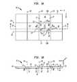
- FIG. 1Ais a plan view illustrating a wafer or portion of a wafer including a plurality of microelectronic elements attached at peripheral edges, in accordance with a stage in a method of fabricating a stacked microelectronic unit according to an embodiment of the invention.
- FIG. 1Bis a sectional view of the wafer or portion of wafer through line 1 B- 1 B of FIG. 1A .
- FIGS. 2A , 2 B, 3 , 4 , 5 , 6 , 7 and 8 Aare sectional views illustrating stages in a method of fabricating a stacked microelectronic unit according to an embodiment of the invention.
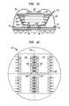
- FIG. 8Bis a fragmentary partial plan view of a stacked assembly in accordance with the stage of fabrication corresponding to the sectional view of FIG. 8A .
- FIGS. 9 and 10Aare sectional views illustrating stages subsequent to the stage illustrated in FIGS. 8A-B , in a method of fabricating a stacked microelectronic unit according to an embodiment of the invention.
- FIG. 10Bis a sectional view illustrating a stacked microelectronic unit in accordance with a variation of the embodiment illustrated in FIG. 10A .
- FIG. 10Cis a sectional view of a stacked assembly in a stage of a method in accordance with an embodiment of the invention.
- FIG. 10Dis a fragmentary partial plan view corresponding to the sectional view of FIG. 10C , the sectional view in FIG. 10C being taken through line 10 C- 10 C of FIG. 10D .
- FIG. 11is a sectional view of a stacked microelectronic unit and its external interconnection to other elements in accordance with an embodiment of the invention.
- FIG. 12is a fragmentary partial plan view of a stacked assembly in a stage of a method in accordance with a variation of the embodiment of invention shown in FIGS. 2A through 10A .
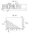
- FIG. 13contains sectional views illustrating a series of successive stages (A) through (D) in a method of fabricating a stacked microelectronic unit in accordance with an embodiment of the invention.
- FIG. 14is a sectional view illustrating a stacked assembly in a stage subsequent to stage (D) of FIG. 13 in a method of fabricating a stacked microelectronic unit in accordance with an embodiment of the invention.
- FIG. 15is a sectional view illustrating a stacked assembly in a stage subsequent to the stage shown in FIG. 14 in a method of fabricating a stacked microelectronic unit in accordance with an embodiment of the invention.
- FIG. 16is a sectional view illustrating a. microelectronic element contained within a stacked assembly in accordance with a variation of the embodiment of the invention illustrated in FIGS. 13 through 15 .
- FIG. 17is a fragmentary partial plan view illustrating a reconstituted wafer for fabrication into stacked microelectronic units in accordance with one or more of the embodiments of the invention.
- FIGS. 1A-Cillustrate an array, or a portion of an array of microelectronic elements, such as may be provided on a semiconductor wafer.
- FIG. 1Ais a top plan view of a wafer 10 or portion of a wafer and includes a plurality of microelectronic elements 12 , 12 ′ (twelve prime), 12 ′′ (twelve double prime), each microelectronic element being shown as a rectangle. As seen in FIG. 1A , each microelectronic element is positioned side by side and adjacent to one another.
- the wafercan be in the shape of a circular wafer.
- the wafer 10 or wafer portionis referred to as “wafer”.
- the wafer 10may include numerous rows of microelectronic elements 12 aligned along an X-axis and a Y-axis.
- the wafermay include any number of microelectronic elements, including as little as tow or as many as is desirable.
- the microelectronic elementsare formed integral with one another using semiconductor fabrication techniques.
- Each of the microelectronic elements of the waferis typically of the same type.
- the microelectronic elementscan have memory function, logic or processor function or a combination of logic and processor functions, among other possible types.
- each of the microelectronic elementsincludes a flash memory.
- each microelectronic elementcan be a dedicated flash memory chip.
- Wafer 10 in FIG. 1Ahas a top edge 15 , a right edge 13 , a left edge 11 and a bottom edge 17 .
- FIG. 1Cis an elevated side view of wafer 10 taken along line 1 B ( FIG. 1A ), showing left edge 11 and right edge 13 of wafer 10 .
- FIG. 1Calso shows that each microelectronic element of wafer 10 also has a front face 14 and an oppositely-facing rear face 16 . Note that in FIG. 1C , the front face 14 of wafer 10 has been turned over such that it faces downward in the figure.
- each microelectronic element 12has a first edge 18 , a second edge 20 , a third edge 19 and a fourth edge 21 .
- a first edge 18 of one microelectronic element 12abuts (or is attached to) second edge 20 of a second and adjacent microelectronic element 12 .
- a third edge 19FIG. 1A
- microelectronic element 12is attached to a fourth edge 21 of an adjacent microelectronic element.
- a microelectronic element 12 ′′ positioned in a middle row of the wafer portion 10is bordered by an adjacent microelectronic element at all four edges, as shown in FIG. 1A .
- each of first edge 18 , second edge 20 , third edge 19 and fourth edge 21extends from the front face 14 ( FIG. 1C ) to the rear face 16 ( FIG. 1C ) of the microelectronic element 12 .
- Portions of wafer 10 where adjacent microelectronic elements contact one anotherform saw lanes or strips 23 and 25 where the wafer can be cut without damaging the individual microelectronic elements. For instance, as shown in FIG. 1B , second edge 20 ′ of microelectronic element 12 ′ abuts first edge 18 ′ of microelectronic element 12 ′′ and forms a saw lane 23 . Similarly, throughout the wafer 10 , saw lanes 23 (shown in FIGS. 1A and 1C ) are located at positions where microelectronic elements 12 abut one another.
- each microelectronic elementincludes a plurality of contacts 22 ′′ exposed at the respective front face 14 of the microelectronic element 12 .
- the contacts 22can be, for example, bond pads or lands of the microelectronic elements as originally formed in a wafer fabrication facility.
- Each microelectronic element of the uncut wafer 10has a device region 26 (area within dashed lines 27 ) in which active semiconductor devices and typically also passive devices are disposed.
- Each microelectronic elementalso includes a non-device region disposed beyond edges of the device region 26 where no active semiconductor devices or passive devices are disposed. Note that the bounded area of device region 26 is shown by solid lines in FIG. 1C .
- an assembly including a plurality of stacked microelectronic elementsis fabricated by simultaneously processing a plurality of microelectronic elements en masse. Moreover, processing can be carried out simultaneously as to microelectronic elements which are arranged in form of an array, similar to the processing of an original wafer containing such microelectronic elements.
- FIGS. 2A-10Aillustrate stages in a method of forming a package or assembly of stacked microelectronic elements in accordance with a first fabrication embodiment.
- original, wafer 10is first separated into individual microelectronic elements and then selected ones of the individual microelectronic elements are attached in form of an array to a carrier layer for further processing.
- the array of selected microelectronic elementscan be considered a “reconstituted wafer” which is then available for processing according to wafer-level processing techniques.
- FIG. 2illustrates a stage of fabrication in which an original wafer 10 is separated into individual microelectronic elements 12 by severing, e.g., sawing or scribing wafer 10 along the dicing lanes 23 and 25 ( FIG. 1A ).
- severinge.g., sawing or scribing wafer 10 along the dicing lanes 23 and 25 ( FIG. 1A ).
- FIG. 2Aillustrates a stage of fabrication in which the wafer 10 is separated into individual microelectronic elements 12 by severing, e.g., sawing or scribing the wafer 10 along the dicing lanes 23 and along dicing lanes 25 ( FIG. 1A ).
- severinge.g., sawing or scribing the wafer 10 along the dicing lanes 23 and along dicing lanes 25 ( FIG. 1A ).
- selected ones 12 of the microelectronic elementsi.e., known good die
- FIG. 2Brepresents determination of a known good die 12 a and a rejected die 12 b , the rejected die being removed from further processing.
- a pick-and-place toolcan be used, for example, to place each microelectronic element 12 at the proper position on the carrier 160 to form a layer of microelectronic elements which make up a first reconstituted wafer 110 as shown in sectional view in FIG. 3 .
- the reconstituted wafer 110includes individual microelectronic elements 12 that were selected from the microelectronic elements 12 obtained during the dicing (sawing) stage of FIG. 2 .
- Individual microelectronic elements 12are referred to as the known good die, and are attached to a carrier 160 using an adhesive 162 , with the front face of each die and contacts 22 thereon facing the carrier 160 .
- a pick-and-place toolcan be used to place each microelectronic element at the proper position on the carrier 160 to form reconstituted wafer structure 90 .
- microelectronic elements that make up each reconstituted wafercan be individually selected.
- some of the microelectronic elements of the original waferare of known or suspected marginal or failing quality, they need not be processed into reconstituted wafers. Rather, those microelectronic elements can be left out of the reconstituted wafer such that the reconstituted wafer contains better quality microelectronic elements.
- Selection of the microelectronic elements to go into the reconstituted wafercan be based on various criteria of quality or expected quality based on results of visual, mechanical or electrical inspection or location of the microelectronic element within the original wafer 10 , for example.
- microelectronic elementsmay in fact be tested electrically before placing each one into position on the reconstituted wafer. Whether the microelectronic elements are selected based on visual, mechanical or electrical criteria or other criteria, the microelectronic elements which are selected for inclusion in the reconstituted wafer can be referred to as “known good” microelectronic elements or “known good die”.
- a fill layer 116( FIG. 4 ) is formed which fills spaces 114 of the reconstituted wafer 110 between adjacent microelectronic elements.
- the fill layermay also cover rear faces 118 of the microelectronic elements 112 .
- the fill layercan include a variety of materials.
- the fill layermay include a dielectric material for providing isolation between the microelectronic elements and conductors which may be connected thereto, such as described in the following.
- the fill layermay include one or more inorganic dielectric materials such as an oxide, nitride, which may include silicon dioxide, silicon nitride or other dielectric compound of silicon such as SiCOH, among others, or may include an organic dielectric, among which are various polymers such as epoxies, polyimide, thermoplastics, thermoset plastics, among others.
- the fill layermay be an encapsulant such as commonly used to form an overmold overlying the rear face and edges of an overmold packaged chip.
- the carrier 160then can be removed to expose front faces 117 of the microelectronic elements and the contacts 22 including contact 22 ′ and 22 ′′ of microelectronic elements 12 ′ and 12 ′′, respectively.
- traces 24are formed which extend outwardly from each of the contacts 22 beyond at least some of the edges 18 ′, 20 ′, 18 ′′ and 20 ′′ ( FIG. 5 ) of the microelectronic elements and optionally beyond edges 19 and 21 ( FIG. 1A ) of individual microelectronic elements 12 .
- Traces 24 ′ and 24 ′′ of adjacent microelectronic elements 12 ′ and 12 ′′may meet at a location between the edges 20 ′ and 18 ′′ of the adjacent microelectronic elements.
- Traces 24 ′, 24 ′′( FIG. 5 ) may actually form a single trace extending between contact 22 ′ and contact 22 ′′. However, it is not required that the traces actually contact one another.
- the resulting reconstituted wafer 130( FIG. 5 ) includes the reconstituted wafer 110 with the microelectronic elements 12 ′, 12 ′′ having the overmold or other fill layer 116 covering the rear faces 118 and space 114 .
- Traces 24 , 24 ′, 24 ′′ and 24 ′′′extend from the contacts 22 (including contacts 22 ′, 22 ′′, etc.) along the front faces 117 of the microelectronic elements.
- Front faces 117 of the microelectronic elements 12are adjacent to a front side 132 of the reconstituted wafer.
- the rear faces 118 of the microelectronic elementsare disposed remote from the front side 312 and are adjacent to the rear side 134 of reconstituted wafer 130 .
- a plurality of reconstituted wafers 130can be prepared according to the foregoing described processes, before conducting further processing as described below to form stacked microelectronic units.
- each reconstituted wafer 130can be referred to as a “subassembly” because such subassemblies can be fabricated individually and then assembled and processed to form a stacked microelectronic unit, as will be described below.
- FIG. 6illustrates a stage of fabrication in which the front side 132 of a first subassembly 130 is joined with a packaging layer 140 , e.g., a bottom dielectric substrate which may include organic or inorganic materials or a combination thereof.
- An adhesive layer 162can be used to join the subassembly 130 with the packaging layer 140 .
- the thickness of the first subassembly 130 ( FIG. 7 ) and the microelectronic elements 12 thereincan be reduced by grinding, lapping or polishing such subassembly from its rear side 134 so as to reduce the thickness of each microelectronic element 12 therein.
- a second subassembly 130 A similar to the first subassemblycan then be bonded to the first subassembly using an adhesive layer 162 A, such that the front side 132 of the second subassembly confronts the rear side 134 of the first subassembly, as shown in FIG. 7 .
- microelectronic elements 12 A of the second subassemblyare stacked in registration with corresponding microelectronic elements 12 of the first subassembly, such that at least a portion of the microelectronic elements 12 A of the second subassembly directly overlie the rear faces 118 of microelectronic elements 12 of the first subassembly.
- edges 18 of the microelectronic elements 12 A of the second subassembly 130 Aare aligned in a vertical direction 60 (a direction transverse to the front faces 117 of microelectronic elements 12 ) with corresponding edges 18 of the microelectronic elements 12 of the first subassembly 130 .
- edges 20 of the microelectronic elements 12 A of the second subassembly 130 Acan be aligned in the vertical direction 60 with corresponding edges 20 of the microelectronic elements 12 of the first subassembly.
- edges 19 and 21 ( FIG. 1A ) of microelectronic elements 12 A of the second subassembly 130 Acan be aligned in the vertical direction with respective edges 19 and 21 of the corresponding microelectronic elements 12 of the first subassembly 130 .
- the thickness of the second subassemblyis reduced, such as by grinding, lapping or polishing, that the microelectronic elements 12 A thereof have reduced thickness, as illustrated in FIG. 8A .
- the dielectric material of the fill layer 116 which directly overlies each microelectronic element 12 Acan be removed such that the fill layer only remains between the confronting edges 18 and 20 and between confronting edges 19 and 21 of adjacent microelectronic elements 12 A of the second subassembly, as best seen in the fragmentary partial plan view of FIG. 8B .
- FIG. 8BAs also depicted in FIG.
- the edges of the microelectronic elements 12 A of the second subassembly and the edges of microelectronic elements 12 of the underlying first subassemblyare aligned so as to define streets 123 and 125 of a stacked assembly 30 with the fill layer 116 disposed in the streets.
- the traces 22extend outward beyond the edges 18 , 19 , 20 , 21 of each chip into the streets 123 , 125 between the microelectronic elements.
- a plurality of channels 46are cut into the stacked assembly 30 in alignment with the streets, as illustrated in FIG. 9 .
- the channels 46can be formed using a mechanical cutting instrument not shown in the figures. Examples of such a mechanical cutting instrument can be found in U.S. Pat. Nos. 6,646,289 and 6,972,480, the disclosures of which are hereby incorporated by reference herein. Alternatively, a laser drilling technique can be used to form the channels.
- Channels 46can be formed in the stacked assembly 30 at locations that are between first edges 18 of microelectronic elements 12 , 12 A in the stacked assembly 30 and adjacent second edges 20 of other microelectronic elements 12 , 12 A in the stacked assembly. Channels may also be formed at locations between third edges ( FIG.
- microelectronic elements 12 , 12 Aadjacent thereto.
- the channels 46extend downwardly within the streets adjacent to edges of microelectronic elements 12 , 12 A of respective subassemblies 130 , 130 A.
- the channels 46may be formed such that they do not extend entirely through the stacked assembly 30 .
- the microelectronic elements 12 of the first subassembly 130remain attached to each other because the channels 46 do not extend through the carrier layer 140 underlying the first subassembly 130 .
- the channels 46do extend far enough so as to contact the traces 24 of the first subassembly 130 .
- the channels 46extend through adhesive layer 162 A connecting the first and second subassemblies 130 , 130 A.
- the channelsmay extend through the lower adhesive layer 162 which connects the first subassembly to the carrier layer 140 .
- the channels 46are illustrated having inclined walls 48 , 50 , optionally, the walls may be straight, that is, parallel to each other and oriented in a normal direction to the plane defined by the front faces 117 of the microelectronic elements 12 .
- leads 66may be formed on the walls 48 , 50 of channels 46 .
- the leads 66may be formed by any suitable metal deposition technique, for example, a process that includes sputtering or electroless plating, photolithography and electroplating or any combination thereof.
- a three-dimensional photolithography processmay be employed to define locations of the leads, such as is disclosed in commonly owned U.S. Pat. No. 5,716,759, the disclosure of which is hereby incorporated by reference herein.
- the leads 66extend along walls of the channels 46 and electrically contact the traces 24 of the microelectronic elements 12 , 12 A of each respective subassembly 130 , 130 A.
- the leads 66extend beyond the walls 48 , 50 of channels 46 such that the leads overlie the rear surfaces 118 of microelectronic elements 12 A.
- the leads 66may include ends 75 or pads remote from channels 46 on which solder bumps 74 may be disposed.
- Each lead 66can electrically connect with both a trace 24 of a microelectronic element 12 and a trace 24 A of microelectronic element 12 A, as a result of those traces 24 , 24 A being aligned and exposed at a given wall, e.g. wall 48 of the channel 46 .
- each lead 66can electrically connect with only one of the traces 24 , 24 A exposed at a wall of the channel, e.g., wall 48 .
- a wall of the channele.g., wall 48 .
- the traces 24 , 24 Ain different planes which occur at different positions into and out of the sheet relative to the particular section which is illustrated in FIG. 9 .
- the plane in which trace 24 is found as illustrated in FIG. 9may be offset from the plane in which trace 24 A is found such that trace 24 is closer to the reader when viewed in three dimensions.
- Lead 66which is aligned and connected with trace 24 , would then also be offset from trace 24 A and not in contact with trace 24 A.
- each of the traces 24 , 24 Athen would be attached to different leads 66 which would extend along a wall 48 or 50 and to positions overlying the rear surface 118 of the microelectronic elements 12 A.
- individual packages 80may be severed from the stacked assembly 30 by separating the carrier layer 140 from the stacked assembly and cutting or breaking any material remaining between adjacent microelectronic elements of the stacked assembly.
- a plurality of stacked individual microelectronic units 80result, with each stacked individual unit 80 containing a plurality of microelectronic elements stacked one upon another.
- the carrier layer 140may remain in place and the carrier layer then is severed in alignment with the channels 46 . In such case, a portion of the carrier layer then will be included in each resulting individual stacked unit 80 .
- each stacked microelectronic unit 80at least one or more of the microelectronic elements 12 , 12 A has a front face 117 and contacts 22 which face away from the top face 90 of the stacked unit.
- FIG. 10Bis a fragmentary sectional view illustrating a portion of an individual stacked microelectronic unit 490 having four microelectronic elements 412 , 412 A, 412 B and 412 C stacked therein, the microelectronic elements being joined together through adhesive layers 162 , 162 A, and 162 B. Greater or fewer numbers of vertically stacked microelectronic elements can be included in the package.
- the front face 417 of some of the microelectronic elementscan face toward the rear faces of other microelectronic elements in the microelectronic unit 490 .
- the front face 417 of microelectronic element 412 Afaces toward the rear face 418 of microelectronic element 412 .
- the packageis capable of being externally interconnected to other elements by ends 475 of leads functioning as top unit contacts overlying the top face 490 of the unit.
- the top unit contacts 475are adjacent to the rear face 418 of microelectronic element 412 C.
- the front faces of microelectronic elements 412 , 412 Aface away from the top face 490 of the stacked unit.
- each bottom unit contact 476may be conductively connected to only one trace 424 of one microelectronic element and have no connections to the traces on the other microelectronic elements in the microelectronic unit.
- each bottom unit contact 476may be conductively connected to two, three or more of the traces 424 , 424 A, 424 B, 424 C which are aligned together within the plane in the section illustrated in FIG. 10B .
- FIG. 10Cillustrates a stage of fabrication prior to that in which channels 46 ( FIG. 9 ) are formed.
- FIG. 10Dis a fragmentary partial plan view corresponding thereto, looking towards front faces of microelectronic elements 812 A and microelectronic elements 812 which underlie and are aligned with the microelectronic elements 812 A in a vertical direction 840 of the assembly. As illustrated in FIGS.
- some of the microelectronic elements 812 A which make up an upper subassembly 832 A of the stacked assemblymay have greater or smaller dimensions than microelectronic elements 812 of a lower subassembly 832 therein.
- both the length 834 ′ and width 836 ′ of the front face 817 A of the upper microelectronic element 812 Acan be smaller than the length 834 and width 836 of the front face 817 of the lower microelectronic element 812 that it overlies.
- the length and width of front faces 817 ′, 817 A′ of vertically aligned microelectronic elements 812 ′ and 812 A′ of the stacked assemblyare the same, but these dimensions are different from, i.e., smaller than the dimensions of other microelectronic elements in the stacked assembly 830 .
- traces 824 extending outward from contacts 822 on microelectronic elements 812can have different lengths from the traces 824 which extend outward from the contacts 822 A on microelectronic elements 812 A, since the process of forming an overmold layer 116 ( FIG. 4 ) leaves a surface on which traces of different lengths can be formed by subsequent processing ( FIG. 5 ).
- Many variationscan be made whereby, for example, microelectronic elements of an upper layer have larger size than those of the lower layer.
- smaller dimensioned chipscan be vertically sandwiched between larger dimensioned chips, or larger dimensioned chips can be vertically sandwiched between smaller dimensioned chips.
- An individual stacked assembly 80 , unit or package( FIG. 11 ) can be conductively connected using solder bumps at the front face 220 of the package 80 to an interconnection element 210 , e.g., a dielectric element, substrate, circuit panel or other element having terminals 84 , 86 and conductive wiring therein.
- an interconnection element 210e.g., a dielectric element, substrate, circuit panel or other element having terminals 84 , 86 and conductive wiring therein.
- One or more additional microelectronic elements 230can be attached to a rear face 222 of the package 80 and electrically interconnected by bond wires 82 to the terminals 84 of the interconnection element.
- Such microelectronic element 230can include one or more additional microelectronic elements which supplement the function of the stacked package 80 , e.g., such as a microcontroller, or can include one or more redundancy elements for substitution with one or more microelectronic elements 112 , 112 A, 112 B, or 112 C, etc. of the assembly in case of a problem with such microelectronic element.
- the individual stacked assembly or unit 80may be incorporated into microprocessors, and RF units among other assemblies.
- One or more stacked units 80may incorporate particular types of microelectronic elements such as flash memory or dynamic random access memory (DRAM) units and be incorporated in various units including memory modules, memory cards, and the like.
- DRAMdynamic random access memory
- the stacked unit 80can be mounted with the front face facing either downwardly towards the interconnection element or upwardly away therefrom.
- the one or more additional microelectronic elementscan be mounted either face-up as shown in FIG. 11 or face-down, such that the contact-bearing face is flip-chip mounted to the stacked unit 80 .
- FIG. 12is a fragmentary partial plan view showing a variation of the above embodiment, wherein, after forming the stacked assembly 30 ( FIG. 8 ), the step of forming channels which expose all of the traces 24 , 24 A of both the stacked microelectronic elements 12 , 12 A is omitted. Instead, a series of individual openings 228 are formed between the edges of respective microelectronic elements in alignment with the streets 218 , 220 . Unlike the channels ( FIG. 9 ) formed in the above-described embodiment, each of the openings 228 exposes no more than a single trace 224 of each respective microelectronic element. As shown in FIG.
- traces 224 connected to contacts of two adjacent microelectronic elements 212are exposed within one of the openings 228 between two adjacent microelectronic elements.
- a plurality of traces 224 connected to microelectronic elements of the same subassemblycan be exposed within a single opening 228 .
- a plurality of traces 224 connected to respective subassemblies 130 , 130 A ( FIG. 7 ) of the stacked assembly.can be exposed within a single opening 228
- openings 228can be formed such that no more than one trace of each individual microelectronic element is exposed within each opening 228 .
- all openings 228 in the stacked assemblycan be simultaneously filled with a conductor to form conductive vias connected to single traces of each microelectronic element.
- the openingscan be filled with a metal to form conductive vias by depositing a primary metal, e.g., by sputtering or electroless deposition, and then electroplating the resulting structure.
- a primary metale.g., by sputtering or electroless deposition
- Some of the metal deposited by the electroplating stepmay form a layer overlying the rear faces of the microelectronic elements. Such metal layer can be removed from the rear faces of the microelectronic elements, leaving surfaces of individual conductive vias exposed within each opening 228 .
- the metal layer overlying the rear faces of the microelectronic elements 212can be patterned by photolithography into individual leads extending from the vias onto locations overlying the rear faces of microelectronic elements 212 , similar to the leads 66 overlying the rear faces 118 of microelectronic elements 12 A in FIG. 9 .
- Conductive bumpse.g., solder bumps are balls, may then be formed at ends of the leads, as shown and described above with reference to FIG. 9 .
- a metal compositecan be deposited through a stencil or by screen-printing to fill the openings 228 in the stacked assembly and form leads which overlie the rear faces. Subsequently, the stacked assembly can be heated to cure the metal composite.
- the openingscan be filled at the same time by the same deposition process as that which forms the leads or the openings can be filled at a different time or different process than that which forms the leads.
- the metal compositecan include, for example, a metal-filled paste such as an epoxy-solder composition, silver-filled paste, or other flowable composition having a dielectric, e.g., polymeric component loaded with metal particles.
- the process of forming the leadscan be additive; the leads can be formed by printing the metal composite through a screen or stencil onto the stacked assembly.
- FIGS. 13 through 16illustrate a method of fabricating a stacked assembly containing a plurality of microelectronic elements in accordance with a variation of the above-described embodiment ( FIGS. 2A through 10A ).
- FIG. 13contains a series of sectional views (A) through (D) illustrating successive stages in the fabrication method.
- stage (A) of FIG. 13a reconstituted wafer 130 such as shown and described above ( FIG. 5 ) is bonded with an adhesive layer 162 to a carrier 160 to form a structure similar to that shown in FIG. 6 .
- the reconstituted waferis bonded with the front faces 317 of the microelectronic elements 312 , the contacts 22 thereon and the traces 24 extending therefrom being adjacent to the carrier 160 .
- the tracesmay be such as to extend beyond only one or only some of the edges, e.g., edge 20 —of each microelectronic element.
- stage (B)the reconstituted wafer is thinned to produce reconstituted wafer 310 by reducing the thickness of each microelectronic element 312 and the dielectric layer 116 such as by lapping, grinding or polishing the reconstituted wafer 130 from the rear faces 318 of the microelectronic elements 312 .
- a second reconstituted wafer 130 AAfter thinning the reconstituted wafer 310 to the desired thickness, a second reconstituted wafer 130 A then is bonded (by adhesive layer 162 A) to the first reconstituted wafer 310 with the front faces 317 of the microelectronic elements 312 A facing toward the rear faces 318 of microelectronic elements 312 of the first reconstituted wafer 310 (stage (C)).
- the second reconstituted wafer 310 Ais bonded to the first reconstituted wafer in such way that an edge 340 A of a microelectronic element 312 A of the second reconstituted wafer 130 A occurs at position 350 A which is offset in a lateral direction 360 from the edge 340 of the first reconstituted wafer 310 .
- each of the overlying microelectronic elements 312 Ahas an area overlapping an area of the underlying microelectronic element 312 to which it is bonded.
- Each of the overlying microelectronic elements 312 Ahas an edge 340 A that is displaced in the lateral direction 360 from the edge 340 of the underlying microelectronic element 312 .
- the lateral offset distance between edges of vertically adjacent overlapping microelectronic elementscan range from a few microns to tens of microns or more, for example.
- stage (D)shows the structure after thinning the second reconstituted wafer 130 A in a manner such as described above ( FIG. 13 , stage (B)) to form reconstituted wafer 310 A.
- the sub-processes shown with respect to stages (C) and (D) of FIG. 13then are repeated for forming a third reconstituted wafer 310 B containing microelectronic elements 312 B and a fourth reconstituted wafer 310 C containing microelectronic elements 312 C to form the stacked assembly 330 shown in FIG. 14 .
- notches 346are then cut between adjacent elements to expose the edges of the traces disposed on the front faces of the microelectronic elements in each reconstituted wafer 310 , 310 A, 310 B and 310 C.
- An advantage of forming the stacked assembly in this manneris that process tolerances can improve for forming the leads 366 .
- the lateral displacement of each overlapping microelectronic element in the stacked assembly relative to the microelectronic elements it overliesallows for slope in the sidewalls of each notch 346 formed therein. Increased lateral displacement allows the sidewalls of each notch 346 to be more heavily sloped, i.e., at a greater angle from the vertical. “Vertical” is defined herein as a normal angle to the plane defined by the contact-bearing surface of a microelectronic element, e.g., element 312 . Despite greater slope of the wall, the notching operation, performed, e.g., by cutting or laser drilling exposes the edges of the traces even when the length of such traces is limited.
- FIG. 16is a plan view illustrating a microelectronic element 312 of one reconstituted wafer 310 of a stacked assembly in a variation of the above-described embodiment ( FIG. 15 ).
- a redistribution layer including additional traces 326can be provided which extends between the pads at edge 342 and outwardly beyond a third edge 344 of the microelectronic element 312 .
- edges 344 of overlapping microelectronic elements of each successively stacked reconstituted wafer 310 , 310 A, 310 B and 310 Ccan also be offset from edges 344 of underlying microelectronic elements in a direction 362 .
- leadscan be formed in channels which expose traces 328 along the third edges 344 of the overlapping microelectronic elements, and process tolerance can also be improved for forming such leads.
- alignment features 560 , 562can be formed on the front faces 517 each microelectronic element 512 of the reconstituted wafer at a stage of fabrication when the outwardly extending traces 524 are formed.
- the alignment featurescan be formed of metal simultaneously with the traces 524 by the same processing which forms the traces, such processing illustrated and described above with respect to FIG. 5 .
- the alignment featurescan be formed by different processing from that which forms the traces. Stated another way, the alignment features can be formed using all the same processing steps as used to form the traces or by performing at least one processing step different from the processing steps used to form the redistribution traces.
- the alignment featuresWhen the alignment features are formed by different processing, they may include a material which is not included in the traces 524 .
- traces 524may include a material, e.g., a metal which is not included in the alignment features.
- the alignment featuresmay be formed to include a material which is particularly reflective of a wavelength of a source, e.g., an infrared source used to illuminate the alignment features.
- the alignment featuresmay include two or more types of features, e.g., closed features 560 and open features 562 to permit edges of each microelectronic element 512 to be distinguished and to facilitate alignment of each microelectronic subassembly within two dimensions.
- the alignment features 560 , 562may be aligned with the area of each underlying microelectronic element 512 such that the alignment features do not extend beyond the edges of each microelectronic element 512 .
- some or all alignment features, e.g., feature 560 ′may be only partially aligned with the area of the microelectronic element 512 , such that the alignment feature extends beyond an edge of the microelectronic element 512 .
- alignment features 560 ′′ and 562 ′′are disposed at locations which lie beyond the edges 518 ′, 519 ′ of the microelectronic element 512 ′.
- Such alignment features 560 ′′, 562 ′′may be aligned entirely or partially with the area that the later formed channels 46 ( FIG. 9 ) will occupy. In this way, alignment features can be provided while at the same time permitting a compact layout to be achieved in the microelectronic elements.
- the alignment features 560 , 562 at the front face 517 of the first microelectronic subassembly 130may be illuminated and detected by instruments disposed above the rear faces of microelectronic elements 12 that subassembly 130 when assembling a next subassembly 130 A thereto in a process such as shown and described above ( FIG. 7 ).
- the alignment features 560 , 562 at the front face 517 of the first microelectronic subassembly 130 and similar alignment features of the second microelectronic assembly 130 Amay be illuminated and detected by instruments disposed below the carrier layer 140 ( FIG. 7 ) and below the front faces of microelectronic elements 12 of the first subassembly 130 .
- the carrier layer 140FIG. 7
Landscapes
- Engineering & Computer Science (AREA)
- Microelectronics & Electronic Packaging (AREA)
- Power Engineering (AREA)
- Computer Hardware Design (AREA)
- Physics & Mathematics (AREA)
- Condensed Matter Physics & Semiconductors (AREA)
- General Physics & Mathematics (AREA)
- Manufacturing & Machinery (AREA)
- Wire Bonding (AREA)
- Internal Circuitry In Semiconductor Integrated Circuit Devices (AREA)
- Packaging Frangible Articles (AREA)
Abstract
Description
Claims (38)
Priority Applications (1)
| Application Number | Priority Date | Filing Date | Title |
|---|---|---|---|
| US12/670,952US8461672B2 (en) | 2007-07-27 | 2008-07-25 | Reconstituted wafer stack packaging with after-applied pad extensions |
Applications Claiming Priority (3)
| Application Number | Priority Date | Filing Date | Title |
|---|---|---|---|
| US96220007P | 2007-07-27 | 2007-07-27 | |
| PCT/US2008/009207WO2009017758A2 (en) | 2007-07-27 | 2008-07-25 | Reconstituted wafer stack packaging with after-applied pad extensions |
| US12/670,952US8461672B2 (en) | 2007-07-27 | 2008-07-25 | Reconstituted wafer stack packaging with after-applied pad extensions |
Related Parent Applications (1)
| Application Number | Title | Priority Date | Filing Date |
|---|---|---|---|
| PCT/US2008/009207A-371-Of-InternationalWO2009017758A2 (en) | 2007-07-27 | 2008-07-25 | Reconstituted wafer stack packaging with after-applied pad extensions |
Related Child Applications (1)
| Application Number | Title | Priority Date | Filing Date |
|---|---|---|---|
| US13/911,555ContinuationUS8883562B2 (en) | 2007-07-27 | 2013-06-06 | Reconstituted wafer stack packaging with after-applied pad extensions |
Publications (2)
| Publication Number | Publication Date |
|---|---|
| US20110006432A1 US20110006432A1 (en) | 2011-01-13 |
| US8461672B2true US8461672B2 (en) | 2013-06-11 |
Family
ID=39768837
Family Applications (2)
| Application Number | Title | Priority Date | Filing Date |
|---|---|---|---|
| US12/670,952Expired - Fee RelatedUS8461672B2 (en) | 2007-07-27 | 2008-07-25 | Reconstituted wafer stack packaging with after-applied pad extensions |
| US13/911,555ActiveUS8883562B2 (en) | 2007-07-27 | 2013-06-06 | Reconstituted wafer stack packaging with after-applied pad extensions |
Family Applications After (1)
| Application Number | Title | Priority Date | Filing Date |
|---|---|---|---|
| US13/911,555ActiveUS8883562B2 (en) | 2007-07-27 | 2013-06-06 | Reconstituted wafer stack packaging with after-applied pad extensions |
Country Status (6)
| Country | Link |
|---|---|
| US (2) | US8461672B2 (en) |
| EP (1) | EP2186134A2 (en) |
| JP (1) | JP5572089B2 (en) |
| KR (1) | KR101458538B1 (en) |
| CN (1) | CN101809739B (en) |
| WO (1) | WO2009017758A2 (en) |
Cited By (18)
| Publication number | Priority date | Publication date | Assignee | Title |
|---|---|---|---|---|
| US20110221053A1 (en)* | 2010-03-11 | 2011-09-15 | Qualcomm Incorporated | Pre-processing to reduce wafer level warpage |
| US8664772B2 (en) | 2012-02-21 | 2014-03-04 | Broadcom Corporation | Interface substrate with interposer |
| US8749072B2 (en) | 2012-02-24 | 2014-06-10 | Broadcom Corporation | Semiconductor package with integrated selectively conductive film interposer |
| US8829654B2 (en) | 2012-02-21 | 2014-09-09 | Broadcom Corporation | Semiconductor package with interposer |
| US8872321B2 (en) | 2012-02-24 | 2014-10-28 | Broadcom Corporation | Semiconductor packages with integrated heat spreaders |
| US8883562B2 (en)* | 2007-07-27 | 2014-11-11 | Tessera, Inc. | Reconstituted wafer stack packaging with after-applied pad extensions |
| US8928128B2 (en) | 2012-02-27 | 2015-01-06 | Broadcom Corporation | Semiconductor package with integrated electromagnetic shielding |
| US8957516B2 (en) | 2012-01-24 | 2015-02-17 | Broadcom Corporation | Low cost and high performance flip chip package |
| US8999810B2 (en) | 2006-10-10 | 2015-04-07 | Tessera, Inc. | Method of making a stacked microelectronic package |
| US9048234B2 (en) | 2006-10-10 | 2015-06-02 | Tessera, Inc. | Off-chip vias in stacked chips |
| US9275976B2 (en) | 2012-02-24 | 2016-03-01 | Broadcom Corporation | System-in-package with integrated socket |
| US9293393B2 (en) | 2011-12-14 | 2016-03-22 | Broadcom Corporation | Stacked packaging using reconstituted wafers |
| US9548251B2 (en) | 2012-01-12 | 2017-01-17 | Broadcom Corporation | Semiconductor interposer having a cavity for intra-interposer die |
| US20170278836A1 (en)* | 2012-08-02 | 2017-09-28 | Infineon Technologies Ag | Integrated System and Method of Making the Integrated System |
| US11751338B1 (en) | 2011-05-11 | 2023-09-05 | Vicor Corporation | Panel-molded electronic assemblies |
| US12096549B1 (en)* | 2015-06-04 | 2024-09-17 | Vicor Corporation | Panel molded electronic assemblies with multi-surface conductive contacts |
| US12200862B1 (en) | 2018-12-12 | 2025-01-14 | Vicor Corporation | Panel molded electronic assemblies with integral terminals |
| USRE50365E1 (en) | 2015-01-14 | 2025-04-08 | Vicor Corporation | Power adapter packaging |
Families Citing this family (57)
| Publication number | Priority date | Publication date | Assignee | Title |
|---|---|---|---|---|
| US7215018B2 (en) | 2004-04-13 | 2007-05-08 | Vertical Circuits, Inc. | Stacked die BGA or LGA component assembly |
| US7829438B2 (en) | 2006-10-10 | 2010-11-09 | Tessera, Inc. | Edge connect wafer level stacking |
| US8569876B2 (en) | 2006-11-22 | 2013-10-29 | Tessera, Inc. | Packaged semiconductor chips with array |
| US7952195B2 (en) | 2006-12-28 | 2011-05-31 | Tessera, Inc. | Stacked packages with bridging traces |
| US8405196B2 (en) | 2007-03-05 | 2013-03-26 | DigitalOptics Corporation Europe Limited | Chips having rear contacts connected by through vias to front contacts |
| US8723332B2 (en) | 2007-06-11 | 2014-05-13 | Invensas Corporation | Electrically interconnected stacked die assemblies |
| WO2009017835A2 (en) | 2007-07-31 | 2009-02-05 | Tessera, Inc. | Semiconductor packaging process using through silicon vias |
| US8551815B2 (en) | 2007-08-03 | 2013-10-08 | Tessera, Inc. | Stack packages using reconstituted wafers |
| US8043895B2 (en) | 2007-08-09 | 2011-10-25 | Tessera, Inc. | Method of fabricating stacked assembly including plurality of stacked microelectronic elements |
| WO2009035849A2 (en) | 2007-09-10 | 2009-03-19 | Vertical Circuits, Inc. | Semiconductor die mount by conformal die coating |
| JP5629580B2 (en) | 2007-09-28 | 2014-11-19 | テッセラ,インコーポレイテッド | Flip chip interconnect with double posts |
| CN101999167B (en) | 2008-03-12 | 2013-07-17 | 伊文萨思公司 | Support mounted electrically interconnected die assembly |
| US9153517B2 (en) | 2008-05-20 | 2015-10-06 | Invensas Corporation | Electrical connector between die pad and z-interconnect for stacked die assemblies |
| US7863159B2 (en) | 2008-06-19 | 2011-01-04 | Vertical Circuits, Inc. | Semiconductor die separation method |
| JP5639052B2 (en) | 2008-06-16 | 2014-12-10 | テッセラ,インコーポレイテッド | Edge stacking at wafer level |
| WO2010104610A2 (en)* | 2009-03-13 | 2010-09-16 | Tessera Technologies Hungary Kft. | Stacked microelectronic assemblies having vias extending through bond pads |
| WO2010151578A2 (en) | 2009-06-26 | 2010-12-29 | Vertical Circuits, Inc. | Electrical interconnect for die stacked in zig-zag configuration |
| US8299446B2 (en)* | 2009-08-12 | 2012-10-30 | Ultratech, Inc. | Sub-field enhanced global alignment |
| US8242543B2 (en)* | 2009-08-26 | 2012-08-14 | Qualcomm Incorporated | Semiconductor wafer-to-wafer bonding for dissimilar semiconductor dies and/or wafers |
| WO2011056668A2 (en) | 2009-10-27 | 2011-05-12 | Vertical Circuits, Inc. | Selective die electrical insulation additive process |
| TWI544604B (en) | 2009-11-04 | 2016-08-01 | 英維瑟斯公司 | Stacked die assembly having reduced stress electrical interconnects |
| DE202010000751U1 (en) | 2010-01-08 | 2011-05-12 | Big Dutchman International Gmbh | Drive device for a membrane filtration device |
| US8796135B2 (en) | 2010-07-23 | 2014-08-05 | Tessera, Inc. | Microelectronic elements with rear contacts connected with via first or via middle structures |
| US9640437B2 (en) | 2010-07-23 | 2017-05-02 | Tessera, Inc. | Methods of forming semiconductor elements using micro-abrasive particle stream |
| US8580607B2 (en) | 2010-07-27 | 2013-11-12 | Tessera, Inc. | Microelectronic packages with nanoparticle joining |
| US8685793B2 (en) | 2010-09-16 | 2014-04-01 | Tessera, Inc. | Chip assembly having via interconnects joined by plating |
| US8686565B2 (en) | 2010-09-16 | 2014-04-01 | Tessera, Inc. | Stacked chip assembly having vertical vias |
| US8847380B2 (en) | 2010-09-17 | 2014-09-30 | Tessera, Inc. | Staged via formation from both sides of chip |
| US8610259B2 (en) | 2010-09-17 | 2013-12-17 | Tessera, Inc. | Multi-function and shielded 3D interconnects |
| US8587126B2 (en) | 2010-12-02 | 2013-11-19 | Tessera, Inc. | Stacked microelectronic assembly with TSVs formed in stages with plural active chips |
| US8637968B2 (en) | 2010-12-02 | 2014-01-28 | Tessera, Inc. | Stacked microelectronic assembly having interposer connecting active chips |
| US8736066B2 (en) | 2010-12-02 | 2014-05-27 | Tessera, Inc. | Stacked microelectronic assemby with TSVS formed in stages and carrier above chip |
| US8610264B2 (en) | 2010-12-08 | 2013-12-17 | Tessera, Inc. | Compliant interconnects in wafers |
| US8853558B2 (en) | 2010-12-10 | 2014-10-07 | Tessera, Inc. | Interconnect structure |
| US9070423B2 (en)* | 2013-06-11 | 2015-06-30 | Invensas Corporation | Single package dual channel memory with co-support |
| DE202014006595U1 (en) | 2014-08-18 | 2015-11-19 | Big Dutchman International Gmbh | Filter element for the separation of particles from a particle-loaded crude gas stream |
| US9633971B2 (en) | 2015-07-10 | 2017-04-25 | Invensas Corporation | Structures and methods for low temperature bonding using nanoparticles |
| US10886250B2 (en) | 2015-07-10 | 2021-01-05 | Invensas Corporation | Structures and methods for low temperature bonding using nanoparticles |
| US9825002B2 (en) | 2015-07-17 | 2017-11-21 | Invensas Corporation | Flipped die stack |
| US9871019B2 (en) | 2015-07-17 | 2018-01-16 | Invensas Corporation | Flipped die stack assemblies with leadframe interconnects |
| US9490195B1 (en) | 2015-07-17 | 2016-11-08 | Invensas Corporation | Wafer-level flipped die stacks with leadframes or metal foil interconnects |
| JP2017060004A (en)* | 2015-09-16 | 2017-03-23 | 株式会社東芝 | Encoding device, decoding device, encoding program, decoding program, and streaming system |
| US10319639B2 (en) | 2017-08-17 | 2019-06-11 | Semiconductor Components Industries, Llc | Thin semiconductor package and related methods |
| US11342189B2 (en) | 2015-09-17 | 2022-05-24 | Semiconductor Components Industries, Llc | Semiconductor packages with die including cavities and related methods |
| US9508691B1 (en) | 2015-12-16 | 2016-11-29 | Invensas Corporation | Flipped die stacks with multiple rows of leadframe interconnects |
| US10566310B2 (en) | 2016-04-11 | 2020-02-18 | Invensas Corporation | Microelectronic packages having stacked die and wire bond interconnects |
| US20170318273A1 (en)* | 2016-04-28 | 2017-11-02 | Qualcomm Incorporated | Shift-and-match fusion of color and mono images |
| US9595511B1 (en) | 2016-05-12 | 2017-03-14 | Invensas Corporation | Microelectronic packages and assemblies with improved flyby signaling operation |
| US9728524B1 (en) | 2016-06-30 | 2017-08-08 | Invensas Corporation | Enhanced density assembly having microelectronic packages mounted at substantial angle to board |
| US10276441B2 (en)* | 2017-06-30 | 2019-04-30 | Taiwan Semiconductor Manufacturing Co., Ltd. | Protected chip-scale package (CSP) pad structure |
| US11361970B2 (en) | 2017-08-17 | 2022-06-14 | Semiconductor Components Industries, Llc | Silicon-on-insulator die support structures and related methods |
| US11404276B2 (en) | 2017-08-17 | 2022-08-02 | Semiconductor Components Industries, Llc | Semiconductor packages with thin die and related methods |
| US11348796B2 (en) | 2017-08-17 | 2022-05-31 | Semiconductor Components Industries, Llc | Backmetal removal methods |
| US11404277B2 (en) | 2017-08-17 | 2022-08-02 | Semiconductor Components Industries, Llc | Die sidewall coatings and related methods |
| FR3109466B1 (en) | 2020-04-16 | 2024-05-17 | St Microelectronics Grenoble 2 | Device for supporting an electronic chip and corresponding manufacturing method |
| JP2024501559A (en) | 2020-12-30 | 2024-01-12 | アデイア セミコンダクター ボンディング テクノロジーズ インコーポレイテッド | Structures with conductive features and methods of forming the same |
| KR20240001408U (en) | 2023-02-13 | 2024-08-20 | 이상오 | a watertight and keeping warm gaiters |
Citations (240)
| Publication number | Priority date | Publication date | Assignee | Title |
|---|---|---|---|---|
| US4074342A (en) | 1974-12-20 | 1978-02-14 | International Business Machines Corporation | Electrical package for lsi devices and assembly process therefor |
| US4500905A (en) | 1981-09-30 | 1985-02-19 | Tokyo Shibaura Denki Kabushiki Kaisha | Stacked semiconductor device with sloping sides |
| US4765864A (en) | 1987-07-15 | 1988-08-23 | Sri International | Etching method for producing an electrochemical cell in a crystalline substrate |
| US4842699A (en) | 1988-05-10 | 1989-06-27 | Avantek, Inc. | Method of selective via-hole and heat sink plating using a metal mask |
| US4897708A (en) | 1986-07-17 | 1990-01-30 | Laser Dynamics, Inc. | Semiconductor wafer array |
| US4954875A (en) | 1986-07-17 | 1990-09-04 | Laser Dynamics, Inc. | Semiconductor wafer array with electrically conductive compliant material |
| US5322816A (en) | 1993-01-19 | 1994-06-21 | Hughes Aircraft Company | Method for forming deep conductive feedthroughs |
| US5343071A (en) | 1993-04-28 | 1994-08-30 | Raytheon Company | Semiconductor structures having dual surface via holes |
| FR2704690A1 (en) | 1993-04-27 | 1994-11-04 | Thomson Csf | Method for encapsulating semiconductor wafers, device obtained by this process and application to the interconnection of wafers in three dimensions. |
| US5412539A (en) | 1993-10-18 | 1995-05-02 | Hughes Aircraft Company | Multichip module with a mandrel-produced interconnecting decal |
| US5424245A (en) | 1994-01-04 | 1995-06-13 | Motorola, Inc. | Method of forming vias through two-sided substrate |
| US5426072A (en) | 1993-01-21 | 1995-06-20 | Hughes Aircraft Company | Process of manufacturing a three dimensional integrated circuit from stacked SOI wafers using a temporary silicon substrate |
| US5466634A (en) | 1994-12-20 | 1995-11-14 | International Business Machines Corporation | Electronic modules with interconnected surface metallization layers and fabrication methods therefore |
| DE19516487C1 (en) | 1995-05-05 | 1996-07-25 | Fraunhofer Ges Forschung | Vertical integration process for microelectronic system |
| US5563084A (en) | 1994-09-22 | 1996-10-08 | Fraunhofer-Gesellschaft zur F orderung der angewandten Forschung e.V. | Method of making a three-dimensional integrated circuit |
| US5571754A (en) | 1995-07-26 | 1996-11-05 | International Business Machines Corporation | Method of fabrication of endcap chip with conductive, monolithic L-connect for multichip stack |
| US5604673A (en) | 1995-06-07 | 1997-02-18 | Hughes Electronics | Low temperature co-fired ceramic substrates for power converters |
| US5608264A (en) | 1995-06-05 | 1997-03-04 | Harris Corporation | Surface mountable integrated circuit with conductive vias |
| US5614766A (en) | 1991-09-30 | 1997-03-25 | Rohm Co., Ltd. | Semiconductor device with stacked alternate-facing chips |
| US5618752A (en) | 1995-06-05 | 1997-04-08 | Harris Corporation | Method of fabrication of surface mountable integrated circuits |
| US5646067A (en) | 1995-06-05 | 1997-07-08 | Harris Corporation | Method of bonding wafers having vias including conductive material |
| US5656553A (en) | 1994-08-22 | 1997-08-12 | International Business Machines Corporation | Method for forming a monolithic electronic module by dicing wafer stacks |
| US5661087A (en) | 1994-06-23 | 1997-08-26 | Cubic Memory, Inc. | Vertical interconnect process for silicon segments |
| US5682062A (en) | 1995-06-05 | 1997-10-28 | Harris Corporation | System for interconnecting stacked integrated circuits |
| US5716759A (en) | 1993-09-02 | 1998-02-10 | Shellcase Ltd. | Method and apparatus for producing integrated circuit devices |
| US5766984A (en) | 1994-09-22 | 1998-06-16 | Fraunhofer-Gesellschaft Zur Foerderung Der Angewandten Forschung | Method of making a vertical integrated circuit |
| US5767001A (en) | 1993-05-05 | 1998-06-16 | Siemens Aktiengesellschaft | Process for producing semiconductor components between which contact is made vertically |
| US5804004A (en) | 1992-05-11 | 1998-09-08 | Nchip, Inc. | Stacked devices for multichip modules |
| US5814889A (en) | 1995-06-05 | 1998-09-29 | Harris Corporation | Intergrated circuit with coaxial isolation and method |
| US5817530A (en) | 1996-05-20 | 1998-10-06 | Micron Technology, Inc. | Use of conductive lines on the back side of wafers and dice for semiconductor interconnects |
| WO1998045130A1 (en) | 1997-04-04 | 1998-10-15 | Leedy Glenn J | Three dimensional structure memory |
| US5880010A (en) | 1994-07-12 | 1999-03-09 | Sun Microsystems, Inc. | Ultrathin electronics |
| EP0926723A1 (en) | 1997-11-26 | 1999-06-30 | STMicroelectronics S.r.l. | Process for forming front-back through contacts in micro-integrated electronic devices |
| WO1999040624A1 (en) | 1998-02-06 | 1999-08-12 | Shellcase Ltd. | Integrated circuit device |
| US5946545A (en) | 1994-03-30 | 1999-08-31 | Internatinal Business Machines Corporation | Semiconductor stack structures and fabrication/sparing methods utilizing programmable spare circuit |
| US5973386A (en) | 1996-02-16 | 1999-10-26 | Nec Corporation | Semiconductor substrate having silicon oxide layers formed between polysilicon layers |
| US6002167A (en) | 1995-09-22 | 1999-12-14 | Hitachi Cable, Ltd. | Semiconductor device having lead on chip structure |
| US6022758A (en) | 1994-07-10 | 2000-02-08 | Shellcase Ltd. | Process for manufacturing solder leads on a semiconductor device package |
| US6031274A (en) | 1996-10-11 | 2000-02-29 | Hamamatsu Photonics K.K. | Back irradiation type light-receiving device and method of making the same |
| US6040235A (en) | 1994-01-17 | 2000-03-21 | Shellcase Ltd. | Methods and apparatus for producing integrated circuit devices |
| US6103552A (en) | 1998-08-10 | 2000-08-15 | Lin; Mou-Shiung | Wafer scale packaging scheme |
| EP1041624A1 (en) | 1999-04-02 | 2000-10-04 | Interuniversitair Microelektronica Centrum Vzw | Method of transferring ultra-thin substrates and application of the method to the manufacture of a multilayer thin film device |
| US6130823A (en) | 1999-02-01 | 2000-10-10 | Raytheon E-Systems, Inc. | Stackable ball grid array module and method |
| US6177721B1 (en) | 1998-10-21 | 2001-01-23 | Hyundai Electronics Industries Co., Ltd | Chip stack-type semiconductor package and method for fabricating the same |
| US6177707B1 (en) | 1998-03-02 | 2001-01-23 | U.S. Philips Corporation | Semiconductor device comprising a glass supporting body onto which a substrate with semiconductor elements and a metalization is attached by means of an adhesive |
| JP2001035995A (en) | 1999-07-22 | 2001-02-09 | Seiko Epson Corp | Method for forming through hole in semiconductor chip |
| US6188129B1 (en) | 1997-03-24 | 2001-02-13 | Hyundai Electronics Industries Co., Ltd. | Stacked semiconductor chip package having external terminal pads and stackable chips having a protection layer |
| US6204562B1 (en) | 1999-02-11 | 2001-03-20 | United Microelectronics Corp. | Wafer-level chip scale package |
| US6228686B1 (en) | 1995-09-18 | 2001-05-08 | Tessera, Inc. | Method of fabricating a microelectronic assembly using sheets with gaps to define lead regions |
| US6252305B1 (en) | 2000-02-29 | 2001-06-26 | Advanced Semiconductor Engineering, Inc. | Multichip module having a stacked chip arrangement |
| US6261865B1 (en) | 1998-10-06 | 2001-07-17 | Micron Technology, Inc. | Multi chip semiconductor package and method of construction |
| JP2001210782A (en) | 2000-01-27 | 2001-08-03 | Seiko Epson Corp | Semiconductor chip, multi-chip package, semiconductor device, and electronic device using the same |
| JP2001217386A (en) | 2000-02-03 | 2001-08-10 | Seiko Epson Corp | Semiconductor device, method of manufacturing the same, and electronic device |
| US6277669B1 (en) | 1999-09-15 | 2001-08-21 | Industrial Technology Research Institute | Wafer level packaging method and packages formed |
| US20010024839A1 (en) | 1998-12-17 | 2001-09-27 | Lin Charles Wen Chyang | Bumpless flip chip assembly with strips-in-via and plating |
| US20010048151A1 (en) | 1998-05-30 | 2001-12-06 | Hyundai Electronics Industries Co., Inc. | Stackable ball grid array semiconductor package and fabrication method thereof |
| US6340845B1 (en) | 1999-01-22 | 2002-01-22 | Nec Corporation | Memory package implementing two-fold memory capacity and two different memory functions |
| US6344401B1 (en) | 2000-03-09 | 2002-02-05 | Atmel Corporation | Method of forming a stacked-die integrated circuit chip package on a water level |
| JP2002093944A (en) | 2000-09-11 | 2002-03-29 | Oki Electric Ind Co Ltd | Semiconductor device and its manufacturing method, and stack-type semiconductor device and its manufacturing method |
| US6396710B1 (en) | 2000-05-12 | 2002-05-28 | Raytheon Company | High density interconnect module |
| US20020074637A1 (en) | 2000-12-19 | 2002-06-20 | Intel Corporation | Stacked flip chip assemblies |
| US20020109236A1 (en) | 2001-02-09 | 2002-08-15 | Samsung Electronics Co., Ltd. | Three-dimensional multi-chip package having chip selection pads and manufacturing method thereof |
| US20020113303A1 (en) | 2000-12-18 | 2002-08-22 | Kei Murayama | Mounting structure for semiconductor devices |
| US20020127775A1 (en) | 1999-12-23 | 2002-09-12 | Rambus Inc. | Redistributed bond pads in stacked integrated circuit die package |
| US20020132465A1 (en) | 1997-04-04 | 2002-09-19 | Elm Technology Corporation | Reconfigurable integrated circuit memory |
| US6472293B2 (en) | 1999-04-13 | 2002-10-29 | Oki Electric Industry Co., Ltd. | Method for manufacturing an interconnect structure for stacked semiconductor device |
| US6472247B1 (en) | 2000-06-26 | 2002-10-29 | Ricoh Company, Ltd. | Solid-state imaging device and method of production of the same |
| US20020171145A1 (en) | 2001-05-21 | 2002-11-21 | Akifumi Higuchi | BGA type semiconductor device, tape carrier for semiconductor device, and semiconductor device using said tape carrier |
| US6486546B2 (en) | 1998-08-21 | 2002-11-26 | Micron Technology, Inc. | Low profile multi-IC chip package connector |
| US6492201B1 (en) | 1998-07-10 | 2002-12-10 | Tessera, Inc. | Forming microelectronic connection components by electrophoretic deposition |
| US6498381B2 (en) | 2001-02-22 | 2002-12-24 | Tru-Si Technologies, Inc. | Semiconductor structures having multiple conductive layers in an opening, and methods for fabricating same |
| US6498387B1 (en) | 2000-02-15 | 2002-12-24 | Wen-Ken Yang | Wafer level package and the process of the same |
| US20030006494A1 (en) | 2001-07-03 | 2003-01-09 | Lee Sang Ho | Thin profile stackable semiconductor package and method for manufacturing |
| JP2003037758A (en) | 2001-01-12 | 2003-02-07 | Konica Corp | Imaging device |
| US6548391B1 (en) | 1999-05-27 | 2003-04-15 | Fraunhofer-Gesellschaft Zur Foerderung Der Angewandten Forschung E. V. | Method of vertically integrating electric components by means of back contacting |
| US6562653B1 (en) | 1999-01-11 | 2003-05-13 | Intel Corporation | Silicon interposer and multi-chip-module (MCM) with through substrate vias |
| US20030094683A1 (en) | 2001-11-16 | 2003-05-22 | Poo Chia Yong | Stackable semiconductor package and wafer level fabrication method |
| JP2003163324A (en) | 2001-11-27 | 2003-06-06 | Nec Corp | Unit semiconductor device and manufacturing method thereof, and three-dimensional laminated semiconductor device |
| US6582991B1 (en) | 2000-12-14 | 2003-06-24 | Matsushita Electric Industrial Co., Ltd. | Semiconductor device and method for fabricating the same |
| US20030134453A1 (en)* | 2002-01-11 | 2003-07-17 | National Semiconductor Corporation | Process and structure improvements to shellcase style packaging technology |
| US6608377B2 (en) | 2001-01-30 | 2003-08-19 | Samsung Electronics Co., Ltd. | Wafer level package including ground metal layer |
| US6607938B2 (en) | 2001-07-19 | 2003-08-19 | Samsung Electronics Co., Ltd. | Wafer level stack chip package and method for manufacturing same |
| US6621155B1 (en) | 1999-12-23 | 2003-09-16 | Rambus Inc. | Integrated circuit device having stacked dies and impedance balanced transmission lines |
| US6624505B2 (en)* | 1998-02-06 | 2003-09-23 | Shellcase, Ltd. | Packaged integrated circuits and methods of producing thereof |
| US20030209772A1 (en) | 2002-05-13 | 2003-11-13 | National Semiconductor Corporation | Electrical die contact structure and fabrication method |
| US6656827B1 (en) | 2002-10-17 | 2003-12-02 | Taiwan Semiconductor Manufacturing Co., Ltd. | Electrical performance enhanced wafer level chip scale package with ground |
| US20030233704A1 (en) | 2000-04-17 | 2003-12-25 | Miguel Castellote | Air massage system for bathtub |
| US20040014255A1 (en) | 2002-07-22 | 2004-01-22 | Grigg Ford B. | Thick solder mask for confining encapsulant material over selected locations of a substrate, assemblies including the solder mask, and methods |
| US20040016942A1 (en) | 2002-04-24 | 2004-01-29 | Seiko Epson Corporation | Semiconductor device and a method of manufacturing the same, a circuit board and an electronic apparatus |
| US6693358B2 (en) | 2000-10-23 | 2004-02-17 | Matsushita Electric Industrial Co., Ltd. | Semiconductor chip, wiring board and manufacturing process thereof as well as semiconductor device |
| JP2004063569A (en) | 2002-07-25 | 2004-02-26 | Seiko Epson Corp | Semiconductor device and its manufacturing method, circuit board, and electronic equipment |
| WO2004025727A1 (en) | 2002-09-10 | 2004-03-25 | Frank Niklaus | Method for sealing a microcavity and package comprising at least one microcavity |
| US6717254B2 (en) | 2001-02-22 | 2004-04-06 | Tru-Si Technologies, Inc. | Devices having substrates with opening passing through the substrates and conductors in the openings, and methods of manufacture |
| JP2004119473A (en) | 2002-09-24 | 2004-04-15 | Seiko Epson Corp | Semiconductor device and its manufacturing method, circuit board, and electronic equipment |
| US6727576B2 (en) | 2001-10-31 | 2004-04-27 | Infineon Technologies Ag | Transfer wafer level packaging |
| US20040082114A1 (en) | 2002-10-29 | 2004-04-29 | Chih-Horng Horng | Fabrication method of window-type ball grid array semiconductor package |
| US6737300B2 (en) | 2001-01-24 | 2004-05-18 | Advanced Semiconductor Engineering, Inc. | Chip scale package and manufacturing method |
| JP2004153130A (en) | 2002-10-31 | 2004-05-27 | Olympus Corp | Semiconductor device and its manufacturing method |
| US6743660B2 (en) | 2002-01-12 | 2004-06-01 | Taiwan Semiconductor Manufacturing Co., Ltd | Method of making a wafer level chip scale package |
| US20040104454A1 (en) | 2002-10-10 | 2004-06-03 | Rohm Co., Ltd. | Semiconductor device and method of producing the same |
| JP2004158536A (en) | 2002-11-05 | 2004-06-03 | Fujitsu Ltd | Semiconductor device and method of manufacturing semiconductor device |
| US6753208B1 (en) | 1998-03-20 | 2004-06-22 | Mcsp, Llc | Wafer scale method of packaging integrated circuit die |
| US6753205B2 (en) | 2001-09-13 | 2004-06-22 | Tru-Si Technologies, Inc. | Method for manufacturing a structure comprising a substrate with a cavity and a semiconductor integrated circuit bonded to a contact pad located in the cavity |
| US20040155354A1 (en) | 2000-06-02 | 2004-08-12 | Seiko Epson Corporation | Semiconductor device, method of fabricating the same, stack-type semiconductor device, circuit board and electronic instrument |
| US6777767B2 (en) | 1999-12-10 | 2004-08-17 | Shellcase Ltd. | Methods for producing packaged integrated circuit devices & packaged integrated circuit devices produced thereby |
| US6784023B2 (en) | 1996-05-20 | 2004-08-31 | Micron Technology, Inc. | Method of fabrication of stacked semiconductor devices |
| US20040169278A1 (en) | 2001-05-21 | 2004-09-02 | Kinsman Larry D. | Bumped die and wire bonded board-on-chip package |
| US6806559B2 (en) | 2002-04-22 | 2004-10-19 | Irvine Sensors Corporation | Method and apparatus for connecting vertically stacked integrated circuit chips |
| US20040222508A1 (en) | 2003-03-18 | 2004-11-11 | Akiyoshi Aoyagi | Semiconductor device, electronic device, electronic apparatus, method of manufacturing semiconductor device, and method of manufacturing electronic device |
| US20040221451A1 (en) | 2003-05-06 | 2004-11-11 | Micron Technology, Inc. | Method for packaging circuits and packaged circuits |
| EP1482553A2 (en) | 2003-05-26 | 2004-12-01 | Sanyo Electric Co., Ltd. | Semiconductor device and manufacturing method thereof |
| US6828175B2 (en) | 2002-08-29 | 2004-12-07 | Micron Technology, Inc. | Semiconductor component with backside contacts and method of fabrication |
| US20040251525A1 (en) | 2003-06-16 | 2004-12-16 | Shellcase Ltd. | Methods and apparatus for packaging integrated circuit devices |
| WO2004114397A1 (en) | 2003-06-20 | 2004-12-29 | Koninklijke Philips Electronics N.V. | Electronic device, assembly and methods of manufacturing an electronic device |
| US20050003649A1 (en) | 2003-06-09 | 2005-01-06 | Sanyo Electric Co., Ltd. | Semiconductor device and manufacturing method thereof |
| US6844619B2 (en) | 2000-12-01 | 2005-01-18 | Nec Corporation | Compact semiconductor device capable of mounting a plurality of semiconductor chips with high density and method of manufacturing the same |
| US20050012225A1 (en) | 2002-11-15 | 2005-01-20 | Choi Seung-Yong | Wafer-level chip scale package and method for fabricating and using the same |
| US20050046002A1 (en) | 2003-08-26 | 2005-03-03 | Kang-Wook Lee | Chip stack package and manufacturing method thereof |
| US6864172B2 (en) | 2002-06-18 | 2005-03-08 | Sanyo Electric Co., Ltd. | Manufacturing method of semiconductor device |
| US20050051883A1 (en) | 2003-06-19 | 2005-03-10 | Seiko Epson Corporation | Semiconductor device and method of manufacturing the same, circuit board, and electronic instrument |
| US6867123B2 (en) | 2001-02-08 | 2005-03-15 | Renesas Technology Corp. | Semiconductor integrated circuit device and its manufacturing method |
| US20050056903A1 (en) | 2003-08-28 | 2005-03-17 | Satoshi Yamamoto | Semiconductor package and method of manufacturing same |
| US6870249B2 (en) | 2002-12-24 | 2005-03-22 | Oki Electric Industry Co., Ltd. | Semiconductor device and manufacturing method thereof |
| EP1519410A1 (en) | 2003-09-25 | 2005-03-30 | Interuniversitair Microelektronica Centrum vzw ( IMEC) | Method for producing electrical through hole interconnects and devices made thereof |
| US20050067680A1 (en) | 2003-09-30 | 2005-03-31 | Boon Suan Jeung | Castellated chip-scale packages and methods for fabricating the same |
| US20050073035A1 (en) | 2003-09-19 | 2005-04-07 | Moxham Stephen F. | Semiconductor component having stiffener and circuit decal and method of fabrication |
| US6878608B2 (en) | 2001-05-31 | 2005-04-12 | International Business Machines Corporation | Method of manufacture of silicon based package |
| JP2005101067A (en) | 2003-09-22 | 2005-04-14 | Sharp Corp | Substrate wiring structure and wiring forming method |
| US20050095835A1 (en) | 2003-09-26 | 2005-05-05 | Tessera, Inc. | Structure and method of making capped chips having vertical interconnects |
| US20050104179A1 (en) | 2003-07-03 | 2005-05-19 | Shellcase Ltd. | Methods and apparatus for packaging integrated circuit devices |
| US6897148B2 (en) | 2003-04-09 | 2005-05-24 | Tru-Si Technologies, Inc. | Electroplating and electroless plating of conductive materials into openings, and structures obtained thereby |
| US20050156330A1 (en) | 2004-01-21 | 2005-07-21 | Harris James M. | Through-wafer contact to bonding pad |
| DE102004039906A1 (en) | 2004-08-18 | 2005-08-18 | Infineon Technologies Ag | Electronic component with a number of integrated members, is formed by producing members with a surface that contains a circuit, and connecting components using bond wires |
| WO2005081315A2 (en) | 2004-02-18 | 2005-09-01 | Infineon Technologies Ag | Semiconductor component comprising a stack of semiconductor chips and method for producing the same |
| JP2005303031A (en) | 2004-04-13 | 2005-10-27 | Matsushita Electric Ind Co Ltd | Electronic circuit module, multilayer electronic circuit module, and method for manufacturing the same |
| US20050260794A1 (en) | 2002-09-03 | 2005-11-24 | Industrial Technology Research Institute | Method for fabrication of wafer level package incorporating dual compliant layers |
| US20050263866A1 (en) | 2004-05-27 | 2005-12-01 | Chang-Fegn Wan | Hermetic pacakging and method of manufacture and use therefore |
| US6972483B1 (en) | 2004-06-30 | 2005-12-06 | Hynix Semiconductor Inc. | Semiconductor package with improved thermal emission property |
| US20050287783A1 (en) | 2004-06-29 | 2005-12-29 | Kirby Kyle K | Microelectronic devices and methods for forming interconnects in microelectronic devices |
| US6984885B1 (en) | 2000-02-10 | 2006-01-10 | Renesas Technology Corp. | Semiconductor device having densely stacked semiconductor chips |
| US20060006488A1 (en) | 2004-06-30 | 2006-01-12 | Sony Corporation | Solid-state imaging device, camera and method of producing the solid-state imaging device |
| EP1619722A1 (en) | 2003-04-16 | 2006-01-25 | Hamamatsu Photonics K. K. | Method for manufacturing backside-illuminated optical sensor |
| US20060017161A1 (en) | 2004-07-22 | 2006-01-26 | Jae-Sik Chung | Semiconductor package having protective layer for re-routing lines and method of manufacturing the same |
| US20060043601A1 (en) | 2002-11-14 | 2006-03-02 | Wolfgang Pahl | Hermetically encapsulated component and waferscale method for the production thereof |
| US20060043598A1 (en) | 2004-08-31 | 2006-03-02 | Kirby Kyle K | Methods of manufacture of a via structure comprising a plurality of conductive elements, semiconductor die, multichip module, and system including same |
| US20060046471A1 (en) | 2004-08-27 | 2006-03-02 | Kirby Kyle K | Methods for forming vias of varying lateral dimensions and semiconductor components and assemblies including same |
| US20060046348A1 (en) | 2004-09-01 | 2006-03-02 | Kang Byoung Y | Semiconductor chip packages and methods for fabricating the same |
| US20060043556A1 (en) | 2004-08-25 | 2006-03-02 | Chao-Yuan Su | Stacked packaging methods and structures |
| US20060055050A1 (en) | 2004-09-10 | 2006-03-16 | Hideo Numata | Semiconductor device and manufacturing method thereof |
| WO2006027981A1 (en) | 2004-09-08 | 2006-03-16 | Matsushita Electric Industrial Co., Ltd. | Stereoscopic electronic circuit device, electronic device using the same, and method for manufacturing the same |
| US20060055061A1 (en) | 2004-09-02 | 2006-03-16 | Ryuji Hosokawa | Semiconductor device and a method of assembling a semiconductor device |
| US20060068580A1 (en) | 2004-09-28 | 2006-03-30 | Sharp Kabushiki Kaisha | Semiconductor device and fabrication method thereof |
| US20060076670A1 (en) | 2004-10-08 | 2006-04-13 | Lim Ohk K | Micro-electro-mechanical system (MEMS) package having metal sealing member |
| US20060079019A1 (en) | 2004-10-08 | 2006-04-13 | Easetech Korea Co., Ltd. | Method for manufacturing wafer level chip scale package using redistribution substrate |
| US7034401B2 (en) | 2003-12-17 | 2006-04-25 | Tru-Si Technologies, Inc. | Packaging substrates for integrated circuits and soldering methods |
| EP1653510A2 (en) | 2004-10-28 | 2006-05-03 | Sanyo Electric Co., Ltd. | Semiconductor device and manufacturing method of the same |
| US20060094165A1 (en) | 2004-10-29 | 2006-05-04 | Harry Hedler | Method for fabricating semiconductor components |
| US7049170B2 (en) | 2003-12-17 | 2006-05-23 | Tru-Si Technologies, Inc. | Integrated circuits and packaging substrates with cavities, and attachment methods including insertion of protruding contact pads into cavities |
| US20060115932A1 (en) | 1997-12-18 | 2006-06-01 | Farnworth Warren M | Method for fabricating semiconductor components with conductive vias |
| US20060138626A1 (en) | 2004-12-29 | 2006-06-29 | Tessera, Inc. | Microelectronic packages using a ceramic substrate having a window and a conductive surface region |
| EP1686627A1 (en) | 2005-01-28 | 2006-08-02 | Samsung Electro-Mechanics Co., Ltd. | Semiconductor package and method of manufacturing the same |
| US7087459B2 (en) | 2002-12-30 | 2006-08-08 | Dongbu Electronics Co., Ltd. | Method for packaging a multi-chip module of a semiconductor device |
| US20060175697A1 (en) | 2005-02-02 | 2006-08-10 | Tetsuya Kurosawa | Semiconductor device having semiconductor chips stacked and mounted thereon and manufacturing method thereof |
| US7115986B2 (en) | 2001-05-02 | 2006-10-03 | Micron Technology, Inc. | Flexible ball grid array chip scale packages |
| US20060220262A1 (en) | 2005-04-04 | 2006-10-05 | Torsten Meyer | Stacked die package |
| US20060220234A1 (en) | 2005-03-22 | 2006-10-05 | Tessera, Inc. | Wire bonded wafer level cavity package |
| US20060249829A1 (en) | 2005-04-08 | 2006-11-09 | Mitsuaki Katagiri | Stacked type semiconductor device |
| US20060258044A1 (en) | 2005-05-11 | 2006-11-16 | Infineon Technologies Ag | Method of manufacturing a semiconductor device comprising stacked chips and a corresponding semiconductor device |
| US20060292866A1 (en) | 2005-06-23 | 2006-12-28 | Borwick Robert L | Low temperature method for fabricating high-aspect ratio vias and devices fabricated by said method |
| US7160753B2 (en) | 2004-03-16 | 2007-01-09 | Voxtel, Inc. | Silicon-on-insulator active pixel sensors |
| EP1741668A2 (en) | 2005-07-05 | 2007-01-10 | Shinko Electric Industries Co., Ltd. | Method for encasing a MEMS device and packaged device |
| US20070007556A1 (en) | 2003-07-23 | 2007-01-11 | Hamamatsu Photonics K.K. | Backside-illuminated photodetector |
| US20070037379A1 (en) | 2005-08-11 | 2007-02-15 | Ziptronix | 3D IC method and device |
| US20070035001A1 (en) | 2005-08-11 | 2007-02-15 | Jochen Kuhmann | Chip scale package for a micro component |
| US20070045803A1 (en) | 2005-08-26 | 2007-03-01 | Micron Technology, Inc. | Microelectronic device packages, stacked microelectronic device packages, and methods for manufacturing microelectronic devices |
| US20070045862A1 (en) | 2005-09-01 | 2007-03-01 | Micron Technology, Inc. | Stacked microelectronic devices and methods for manufacturing microelectronic devices |
| US20070052050A1 (en) | 2005-09-07 | 2007-03-08 | Bart Dierickx | Backside thinned image sensor with integrated lens stack |
| US7208343B2 (en) | 2002-02-06 | 2007-04-24 | Samsung Electronics Co., Ltd. | Semiconductor chip, chip stack package and manufacturing method |
| US7215018B2 (en) | 2004-04-13 | 2007-05-08 | Vertical Circuits, Inc. | Stacked die BGA or LGA component assembly |
| US20070102802A1 (en) | 2003-09-19 | 2007-05-10 | Samsung Electronics Co., Ltd. | Single chip and stack-type chip semiconductor package and method of manufacturing the same |
| US20070126085A1 (en) | 2005-12-02 | 2007-06-07 | Nec Electronics Corporation | Semiconductor device and method of manufacturing the same |
| US20070132082A1 (en) | 2005-12-12 | 2007-06-14 | Intel Corporation | Copper plating connection for multi-die stack in substrate package |
| EP1801866A2 (en) | 2002-11-05 | 2007-06-27 | Shinko Electric Industries Co., Ltd. | Semiconductor device and method of manufacturing the same |
| US20070148941A1 (en) | 2005-12-27 | 2007-06-28 | Tessera, Inc. | Microelectronic component with photo-imageable substrate |
| US20070158807A1 (en) | 2005-12-29 | 2007-07-12 | Daoqiang Lu | Edge interconnects for die stacking |
| US20070181989A1 (en) | 2006-02-08 | 2007-08-09 | Micron Technology, Inc. | Microelectronic devices, stacked microelectronic devices, and methods for manufacturing such devices |
| US20070190747A1 (en) | 2006-01-23 | 2007-08-16 | Tessera Technologies Hungary Kft. | Wafer level packaging to lidded chips |
| US7285865B2 (en)* | 2005-07-15 | 2007-10-23 | Samsung Electronic Co., Ltd. | Micro-package, multi-stack micro-package, and manufacturing method therefor |
| US20070257350A1 (en) | 2003-11-19 | 2007-11-08 | Kang-Wook Lee | Wafer level stack structure for system-in-package and method thereof |
| US7312521B2 (en) | 2002-04-23 | 2007-12-25 | Sanyo Electric Co., Ltd. | Semiconductor device with holding member |
| US20080083976A1 (en)* | 2006-10-10 | 2008-04-10 | Tessera, Inc. | Edge connect wafer level stacking |
| US20080083977A1 (en)* | 2006-10-10 | 2008-04-10 | Tessera, Inc. | Edge connect wafer level stacking |
| US20080090333A1 (en) | 2006-10-17 | 2008-04-17 | Tessera, Inc. | Microelectronic packages fabricated at the wafer level and methods therefor |
| US20080099907A1 (en) | 2006-10-31 | 2008-05-01 | Tessera Technologies Hungary Kft. | Wafer-level fabrication of lidded chips with electrodeposited dielectric coating |
| US20080099900A1 (en) | 2006-10-31 | 2008-05-01 | Tessera Technologies Hungary Kft. | Wafer-level fabrication of lidded chips with electrodeposited dielectric coating |
| US20080116545A1 (en) | 2006-11-22 | 2008-05-22 | Tessera, Inc. | Packaged semiconductor chips |
| US20080116544A1 (en) | 2006-11-22 | 2008-05-22 | Tessera, Inc. | Packaged semiconductor chips with array |
| US20080122113A1 (en) | 2006-08-17 | 2008-05-29 | Corisis David J | Semiconductor device assemblies and systems including at least one conductive pathway extending around a side of at least one semiconductor device and methods for forming the same |
| US7394152B2 (en)* | 2006-11-13 | 2008-07-01 | China Wafer Level Csp Ltd. | Wafer level chip size packaged chip device with an N-shape junction inside and method of fabricating the same |
| US20080157327A1 (en) | 2007-01-03 | 2008-07-03 | Advanced Chip Engineering Technology Inc. | Package on package structure for semiconductor devices and method of the same |
| US20080166836A1 (en) | 2003-06-03 | 2008-07-10 | Casio Computer Co., Ltd. | Semiconductor package including connected upper and lower interconnections, and manufacturing method thereof |
| US7408249B2 (en)* | 1998-02-06 | 2008-08-05 | Tessera Technologies Hungary Kft. | Packaged integrated circuits and methods of producing thereof |
| US20080246136A1 (en) | 2007-03-05 | 2008-10-09 | Tessera, Inc. | Chips having rear contacts connected by through vias to front contacts |
| US20080284041A1 (en) | 2007-05-18 | 2008-11-20 | Samsung Electronics Co., Ltd. | Semiconductor package with through silicon via and related method of fabrication |
| US20080308921A1 (en) | 2007-06-18 | 2008-12-18 | Jong Hoon Kim | Molded reconfigured wafer, stack package using the same, and method for manufacturing the stack package |
| US20080315407A1 (en) | 2007-06-20 | 2008-12-25 | Vertical Circuits, Inc. | Three-dimensional circuitry formed on integrated circuit device using two-dimensional fabrication |
| US20090009491A1 (en) | 2007-07-04 | 2009-01-08 | Grivna Edward L | Capacitive sensing control knob |
| US20090032966A1 (en) | 2007-08-01 | 2009-02-05 | Jong Ho Lee | Method of fabricating a 3-D device and device made thereby |
| US20090039528A1 (en)* | 2007-08-09 | 2009-02-12 | Tessera, Inc. | Wafer level stacked packages with individual chip selection |
| US7498661B2 (en) | 2003-03-25 | 2009-03-03 | Seiko Epson Corporation | Manufacturing method for semiconductor device, semiconductor device, and electronic apparatus |
| US20090065907A1 (en) | 2007-07-31 | 2009-03-12 | Tessera, Inc. | Semiconductor packaging process using through silicon vias |
| US20090067135A1 (en) | 2005-05-02 | 2009-03-12 | Advanced Systems Japan Inc. | Semiconductor Package Having Socket Function, Semiconductor Module, Electronic Circuit Module and Circuit Board with Socket |
| US7510928B2 (en) | 2006-05-05 | 2009-03-31 | Tru-Si Technologies, Inc. | Dielectric trenches, nickel/tantalum oxide structures, and chemical mechanical polishing techniques |
| US20090121323A1 (en) | 2007-11-08 | 2009-05-14 | Samsung Electronics Co., Ltd | Semiconductor device and method of fabricating the same |
| US20090160065A1 (en)* | 2006-10-10 | 2009-06-25 | Tessera, Inc. | Reconstituted Wafer Level Stacking |
| US20090166840A1 (en) | 2007-12-27 | 2009-07-02 | Samsung Electronics Co., Ltd. | Wafer-level stack package |
| US20090166846A1 (en) | 2007-12-28 | 2009-07-02 | Micron Technology, Inc. | Pass-through 3d interconnect for microelectronic dies and associated systems and methods |
| US20090212381A1 (en) | 2008-02-26 | 2009-08-27 | Tessera, Inc. | Wafer level packages for rear-face illuminated solid state image sensors |
| US7622810B2 (en) | 2002-10-11 | 2009-11-24 | Sanyo Electric Co., Ltd. | Semiconductor device and manufacturing method thereof |
| US20090309235A1 (en) | 2008-06-11 | 2009-12-17 | Stats Chippac, Ltd. | Method and Apparatus for Wafer Level Integration Using Tapered Vias |
| US20090316378A1 (en) | 2008-06-16 | 2009-12-24 | Tessera Research Llc | Wafer level edge stacking |
| US7662710B2 (en) | 2006-09-26 | 2010-02-16 | Hymite A/S | Formation of through-wafer electrical interconnections and other structures using a thin dielectric membrane |
| US7663213B2 (en)* | 2006-11-13 | 2010-02-16 | China Wafer Level Csp Ltd. | Wafer level chip size packaged chip device with a double-layer lead structure and method of fabricating the same |
| US20100053407A1 (en) | 2008-02-26 | 2010-03-04 | Tessera, Inc. | Wafer level compliant packages for rear-face illuminated solid state image sensors |
| US20100065949A1 (en) | 2008-09-17 | 2010-03-18 | Andreas Thies | Stacked Semiconductor Chips with Through Substrate Vias |
| US20100164086A1 (en) | 2006-08-11 | 2010-07-01 | Sanyo Electric Co., Ltd. | Semiconductor device and manufacturing method thereof |
| US20100200966A1 (en) | 2002-09-17 | 2010-08-12 | Marcos Karnezos | Semiconductor multi-package module having package stacked over die-up flip chip ball grid array package and having wire bond interconnect between stacked packages |
| US20100219523A1 (en) | 2006-02-27 | 2010-09-02 | Seng Guan Chow | Stackable integrated circuit package system |
| US20100230795A1 (en) | 2009-03-13 | 2010-09-16 | Tessera Technologies Hungary Kft. | Stacked microelectronic assemblies having vias extending through bond pads |
| US7859115B2 (en) | 2008-11-07 | 2010-12-28 | Hynix Semiconductor Inc. | Semiconductor package for improving characteristics for transmitting signals and power |
| US20110006432A1 (en) | 2007-07-27 | 2011-01-13 | Tessera, Inc. | Reconstituted wafer stack packaging with after-applied pad extensions |
| US20110024890A1 (en) | 2007-06-29 | 2011-02-03 | Stats Chippac, Ltd. | Stackable Package By Using Internal Stacking Modules |
| US7884459B2 (en) | 2003-01-15 | 2011-02-08 | Fujitsu Semiconductor Limited | Semiconductor device suitable for a stacked structure |
| US20110039370A1 (en) | 2005-07-21 | 2011-02-17 | Shinko Electric Industries Co., Ltd. | Electronic parts packaging structure and method of manufacturing the same |
| US7944015B2 (en)* | 2007-07-27 | 2011-05-17 | Sanyo Electric Co., Ltd. | Semiconductor device and method of manufacturing the same |
| US7952195B2 (en) | 2006-12-28 | 2011-05-31 | Tessera, Inc. | Stacked packages with bridging traces |
| US7973416B2 (en) | 2008-05-12 | 2011-07-05 | Texas Instruments Incorporated | Thru silicon enabled die stacking scheme |
| US20110198722A1 (en) | 2007-08-16 | 2011-08-18 | Hynix Semiconductor Inc. | Semiconductor package through-electrode suitable for a stacked semiconductor package and semiconductor package having the same |
| US20110248410A1 (en) | 2007-08-03 | 2011-10-13 | Tessera, Inc. | Stack packages using reconstituted wafers |
| US20120025364A1 (en) | 2005-12-09 | 2012-02-02 | Masataka Hoshino | Semiconductor device and method of manufacturing the same |
Family Cites Families (26)
| Publication number | Priority date | Publication date | Assignee | Title |
|---|---|---|---|---|
| JPS60160645A (en) | 1984-02-01 | 1985-08-22 | Hitachi Ltd | Laminated semiconductor integrated circuit device |
| JPS60206058A (en)* | 1984-03-30 | 1985-10-17 | Fujitsu Ltd | Manufacture of multilayer semiconductor device |
| US5696030A (en) | 1994-09-30 | 1997-12-09 | International Business Machines Corporation | Integrated circuit contacts having improved electromigration characteristics and fabrication methods therefor |
| JPH08306724A (en) | 1995-04-28 | 1996-11-22 | Matsushita Electron Corp | Semiconductor device, manufacturing method and its mounting method |
| JP3423897B2 (en) | 1999-04-01 | 2003-07-07 | 宮崎沖電気株式会社 | Method for manufacturing semiconductor device |
| WO2001015228A1 (en) | 1999-08-19 | 2001-03-01 | Seiko Epson Corporation | Wiring board, method of manufacturing wiring board, electronic device, method of manufacturing electronic device, circuit board and electronic apparatus |
| JP3833859B2 (en)* | 1999-10-14 | 2006-10-18 | ローム株式会社 | Semiconductor device and manufacturing method thereof |
| US6316287B1 (en) | 1999-09-13 | 2001-11-13 | Vishay Intertechnology, Inc. | Chip scale surface mount packages for semiconductor device and process of fabricating the same |
| JP2001156250A (en) | 1999-11-24 | 2001-06-08 | Seiko Epson Corp | Semiconductor chip, multi-chip package, semiconductor device, and electronic equipment using the same |
| NO20001360D0 (en) | 2000-03-15 | 2000-03-15 | Thin Film Electronics Asa | Vertical electrical connections in stack |
| JP3433193B2 (en) | 2000-10-23 | 2003-08-04 | 松下電器産業株式会社 | Semiconductor chip and manufacturing method thereof |
| US20020100600A1 (en)* | 2001-01-26 | 2002-08-01 | Albert Douglas M. | Stackable microcircuit layer formed from a plastic encapsulated microcircuit and method of making the same |
| JP3660918B2 (en)* | 2001-07-04 | 2005-06-15 | 松下電器産業株式会社 | Semiconductor device and manufacturing method thereof |
| TWI241674B (en) | 2001-11-30 | 2005-10-11 | Disco Corp | Manufacturing method of semiconductor chip |
| JP4215571B2 (en) | 2002-06-18 | 2009-01-28 | 三洋電機株式会社 | Manufacturing method of semiconductor device |
| TWI227550B (en) | 2002-10-30 | 2005-02-01 | Sanyo Electric Co | Semiconductor device manufacturing method |
| JP4208840B2 (en) | 2002-12-17 | 2009-01-14 | 富士通マイクロエレクトロニクス株式会社 | Semiconductor device |
| JP4238041B2 (en) | 2003-02-06 | 2009-03-11 | アドバンスト ダイシング テクノロジース リミテッド | Dicing apparatus, dicing method, and manufacturing method of semiconductor device |
| JP2004342862A (en) | 2003-05-16 | 2004-12-02 | Sony Corp | Semiconductor device and its manufacturing method, false wafer and its manufacturing method, and multi-chip module |
| JP2005011856A (en)* | 2003-06-17 | 2005-01-13 | Sony Corp | Chip-like electronic part, its manufacturing method, and its mounting structure |
| JP4401181B2 (en) | 2003-08-06 | 2010-01-20 | 三洋電機株式会社 | Semiconductor device and manufacturing method thereof |
| KR100618837B1 (en) | 2004-06-22 | 2006-09-01 | 삼성전자주식회사 | How to Form a Stack of Thin Wafers for a Wafer Level Package |
| US20060019468A1 (en) | 2004-07-21 | 2006-01-26 | Beatty John J | Method of manufacturing a plurality of electronic assemblies |
| TW200845339A (en)* | 2007-05-07 | 2008-11-16 | Sanyo Electric Co | Semiconductor device and manufacturing method thereof |
| WO2009023462A1 (en) | 2007-08-10 | 2009-02-19 | Spansion Llc | Semiconductor device and method for manufacturing thereof |
| KR100997787B1 (en)* | 2008-06-30 | 2010-12-02 | 주식회사 하이닉스반도체 | Laminated Semiconductor Package and Method of Manufacturing the Same |
- 2008
- 2008-07-25JPJP2010519235Apatent/JP5572089B2/ennot_activeExpired - Fee Related
- 2008-07-25KRKR1020107004470Apatent/KR101458538B1/ennot_activeExpired - Fee Related
- 2008-07-25EPEP08794877Apatent/EP2186134A2/ennot_activeWithdrawn
- 2008-07-25WOPCT/US2008/009207patent/WO2009017758A2/enactiveApplication Filing
- 2008-07-25USUS12/670,952patent/US8461672B2/ennot_activeExpired - Fee Related
- 2008-07-25CNCN200880109094.9Apatent/CN101809739B/ennot_activeExpired - Fee Related
- 2013
- 2013-06-06USUS13/911,555patent/US8883562B2/enactiveActive
Patent Citations (302)
| Publication number | Priority date | Publication date | Assignee | Title |
|---|---|---|---|---|
| US4074342A (en) | 1974-12-20 | 1978-02-14 | International Business Machines Corporation | Electrical package for lsi devices and assembly process therefor |
| US4500905A (en) | 1981-09-30 | 1985-02-19 | Tokyo Shibaura Denki Kabushiki Kaisha | Stacked semiconductor device with sloping sides |
| US4897708A (en) | 1986-07-17 | 1990-01-30 | Laser Dynamics, Inc. | Semiconductor wafer array |
| US4954875A (en) | 1986-07-17 | 1990-09-04 | Laser Dynamics, Inc. | Semiconductor wafer array with electrically conductive compliant material |
| US4765864A (en) | 1987-07-15 | 1988-08-23 | Sri International | Etching method for producing an electrochemical cell in a crystalline substrate |
| US4842699A (en) | 1988-05-10 | 1989-06-27 | Avantek, Inc. | Method of selective via-hole and heat sink plating using a metal mask |
| US5614766A (en) | 1991-09-30 | 1997-03-25 | Rohm Co., Ltd. | Semiconductor device with stacked alternate-facing chips |
| US5804004A (en) | 1992-05-11 | 1998-09-08 | Nchip, Inc. | Stacked devices for multichip modules |
| US5322816A (en) | 1993-01-19 | 1994-06-21 | Hughes Aircraft Company | Method for forming deep conductive feedthroughs |
| US5426072A (en) | 1993-01-21 | 1995-06-20 | Hughes Aircraft Company | Process of manufacturing a three dimensional integrated circuit from stacked SOI wafers using a temporary silicon substrate |
| WO1994025987A1 (en) | 1993-04-27 | 1994-11-10 | Thomson-Csf | Semiconductor chip encapsulation method, device produced by this method and its application to three dimensional chip interconnection |
| FR2704690A1 (en) | 1993-04-27 | 1994-11-04 | Thomson Csf | Method for encapsulating semiconductor wafers, device obtained by this process and application to the interconnection of wafers in three dimensions. |
| US5343071A (en) | 1993-04-28 | 1994-08-30 | Raytheon Company | Semiconductor structures having dual surface via holes |
| US5767001A (en) | 1993-05-05 | 1998-06-16 | Siemens Aktiengesellschaft | Process for producing semiconductor components between which contact is made vertically |
| US5716759A (en) | 1993-09-02 | 1998-02-10 | Shellcase Ltd. | Method and apparatus for producing integrated circuit devices |
| US5412539A (en) | 1993-10-18 | 1995-05-02 | Hughes Aircraft Company | Multichip module with a mandrel-produced interconnecting decal |
| US5424245A (en) | 1994-01-04 | 1995-06-13 | Motorola, Inc. | Method of forming vias through two-sided substrate |
| US6040235A (en) | 1994-01-17 | 2000-03-21 | Shellcase Ltd. | Methods and apparatus for producing integrated circuit devices |
| US5946545A (en) | 1994-03-30 | 1999-08-31 | Internatinal Business Machines Corporation | Semiconductor stack structures and fabrication/sparing methods utilizing programmable spare circuit |
| US5661087A (en) | 1994-06-23 | 1997-08-26 | Cubic Memory, Inc. | Vertical interconnect process for silicon segments |
| US6022758A (en) | 1994-07-10 | 2000-02-08 | Shellcase Ltd. | Process for manufacturing solder leads on a semiconductor device package |
| US5880010A (en) | 1994-07-12 | 1999-03-09 | Sun Microsystems, Inc. | Ultrathin electronics |
| US5656553A (en) | 1994-08-22 | 1997-08-12 | International Business Machines Corporation | Method for forming a monolithic electronic module by dicing wafer stacks |
| US5563084A (en) | 1994-09-22 | 1996-10-08 | Fraunhofer-Gesellschaft zur F orderung der angewandten Forschung e.V. | Method of making a three-dimensional integrated circuit |
| US5766984A (en) | 1994-09-22 | 1998-06-16 | Fraunhofer-Gesellschaft Zur Foerderung Der Angewandten Forschung | Method of making a vertical integrated circuit |
| US5466634A (en) | 1994-12-20 | 1995-11-14 | International Business Machines Corporation | Electronic modules with interconnected surface metallization layers and fabrication methods therefore |
| DE19516487C1 (en) | 1995-05-05 | 1996-07-25 | Fraunhofer Ges Forschung | Vertical integration process for microelectronic system |
| US5618752A (en) | 1995-06-05 | 1997-04-08 | Harris Corporation | Method of fabrication of surface mountable integrated circuits |
| US5814889A (en) | 1995-06-05 | 1998-09-29 | Harris Corporation | Intergrated circuit with coaxial isolation and method |
| US5682062A (en) | 1995-06-05 | 1997-10-28 | Harris Corporation | System for interconnecting stacked integrated circuits |
| US5646067A (en) | 1995-06-05 | 1997-07-08 | Harris Corporation | Method of bonding wafers having vias including conductive material |
| US5608264A (en) | 1995-06-05 | 1997-03-04 | Harris Corporation | Surface mountable integrated circuit with conductive vias |
| US5604673A (en) | 1995-06-07 | 1997-02-18 | Hughes Electronics | Low temperature co-fired ceramic substrates for power converters |
| US5571754A (en) | 1995-07-26 | 1996-11-05 | International Business Machines Corporation | Method of fabrication of endcap chip with conductive, monolithic L-connect for multichip stack |
| US6228686B1 (en) | 1995-09-18 | 2001-05-08 | Tessera, Inc. | Method of fabricating a microelectronic assembly using sheets with gaps to define lead regions |
| US6002167A (en) | 1995-09-22 | 1999-12-14 | Hitachi Cable, Ltd. | Semiconductor device having lead on chip structure |
| US5973386A (en) | 1996-02-16 | 1999-10-26 | Nec Corporation | Semiconductor substrate having silicon oxide layers formed between polysilicon layers |
| US20060121645A1 (en) | 1996-05-20 | 2006-06-08 | Ball Michael B | Method of fabrication of stacked semiconductor devices |
| US6784023B2 (en) | 1996-05-20 | 2004-08-31 | Micron Technology, Inc. | Method of fabrication of stacked semiconductor devices |
| US5817530A (en) | 1996-05-20 | 1998-10-06 | Micron Technology, Inc. | Use of conductive lines on the back side of wafers and dice for semiconductor interconnects |
| US6031274A (en) | 1996-10-11 | 2000-02-29 | Hamamatsu Photonics K.K. | Back irradiation type light-receiving device and method of making the same |
| US6188129B1 (en) | 1997-03-24 | 2001-02-13 | Hyundai Electronics Industries Co., Ltd. | Stacked semiconductor chip package having external terminal pads and stackable chips having a protection layer |
| US6208545B1 (en) | 1997-04-04 | 2001-03-27 | Glenn J. Leedy | Three dimensional structure memory |
| US20090219742A1 (en) | 1997-04-04 | 2009-09-03 | Leedy Glenn J | Three dimensional structure memory |
| WO1998045130A1 (en) | 1997-04-04 | 1998-10-15 | Leedy Glenn J | Three dimensional structure memory |
| US6133640A (en) | 1997-04-04 | 2000-10-17 | Elm Technology Corporation | Three-dimensional structure memory |
| US7138295B2 (en) | 1997-04-04 | 2006-11-21 | Elm Technology Corporation | Method of information processing using three dimensional integrated circuits |
| US7193239B2 (en) | 1997-04-04 | 2007-03-20 | Elm Technology Corporation | Three dimensional structure integrated circuit |
| US6632706B1 (en) | 1997-04-04 | 2003-10-14 | Elm Technology Corporation | Three dimensional structure integrated circuit fabrication process |
| US20030173608A1 (en) | 1997-04-04 | 2003-09-18 | Elm Technology Corporation | Three dimensional structure integrated circuit |
| US7474004B2 (en) | 1997-04-04 | 2009-01-06 | Elm Technology Corporation | Three dimensional structure memory |
| US20090067210A1 (en) | 1997-04-04 | 2009-03-12 | Leedy Glenn J | Three dimensional structure memory |
| US20040070063A1 (en) | 1997-04-04 | 2004-04-15 | Elm Technology Corporation | Three dimensional structure integrated circuit |
| US5915167A (en) | 1997-04-04 | 1999-06-22 | Elm Technology Corporation | Three dimensional structure memory |
| US7504732B2 (en) | 1997-04-04 | 2009-03-17 | Elm Technology Corporation | Three dimensional structure memory |
| US20090175104A1 (en) | 1997-04-04 | 2009-07-09 | Leedy Glenn J | Three dimensional structure memory |
| US20090174082A1 (en) | 1997-04-04 | 2009-07-09 | Glenn J Leedy | Three dimensional structure memory |
| US6563224B2 (en) | 1997-04-04 | 2003-05-13 | Elm Technology Corporation | Three dimensional structure integrated circuit |
| US6551857B2 (en) | 1997-04-04 | 2003-04-22 | Elm Technology Corporation | Three dimensional structure integrated circuits |
| US20090219743A1 (en) | 1997-04-04 | 2009-09-03 | Leedy Glenn J | Three dimensional structure memory |
| US20090219744A1 (en) | 1997-04-04 | 2009-09-03 | Leedy Glenn J | Three dimensional structure memory |
| US20090218700A1 (en) | 1997-04-04 | 2009-09-03 | Leedy Glenn J | Three dimensional structure memory |
| US20090219772A1 (en) | 1997-04-04 | 2009-09-03 | Leedy Glenn J | Three dimensional structure memory |
| US7705466B2 (en) | 1997-04-04 | 2010-04-27 | Elm Technology Corporation | Three dimensional multi layer memory and control logic integrated circuit structure |
| US20090230501A1 (en) | 1997-04-04 | 2009-09-17 | Leedy Glenn J | Three dimensional structure memory |
| US20020132465A1 (en) | 1997-04-04 | 2002-09-19 | Elm Technology Corporation | Reconfigurable integrated circuit memory |
| EP0926723A1 (en) | 1997-11-26 | 1999-06-30 | STMicroelectronics S.r.l. | Process for forming front-back through contacts in micro-integrated electronic devices |
| US20060115932A1 (en) | 1997-12-18 | 2006-06-01 | Farnworth Warren M | Method for fabricating semiconductor components with conductive vias |
| US7408249B2 (en)* | 1998-02-06 | 2008-08-05 | Tessera Technologies Hungary Kft. | Packaged integrated circuits and methods of producing thereof |
| US6624505B2 (en)* | 1998-02-06 | 2003-09-23 | Shellcase, Ltd. | Packaged integrated circuits and methods of producing thereof |
| WO1999040624A1 (en) | 1998-02-06 | 1999-08-12 | Shellcase Ltd. | Integrated circuit device |
| US6646289B1 (en) | 1998-02-06 | 2003-11-11 | Shellcase Ltd. | Integrated circuit device |
| US6177707B1 (en) | 1998-03-02 | 2001-01-23 | U.S. Philips Corporation | Semiconductor device comprising a glass supporting body onto which a substrate with semiconductor elements and a metalization is attached by means of an adhesive |
| US6753208B1 (en) | 1998-03-20 | 2004-06-22 | Mcsp, Llc | Wafer scale method of packaging integrated circuit die |
| US6982475B1 (en) | 1998-03-20 | 2006-01-03 | Mcsp, Llc | Hermetic wafer scale integrated circuit structure |
| US20010048151A1 (en) | 1998-05-30 | 2001-12-06 | Hyundai Electronics Industries Co., Inc. | Stackable ball grid array semiconductor package and fabrication method thereof |
| US6492201B1 (en) | 1998-07-10 | 2002-12-10 | Tessera, Inc. | Forming microelectronic connection components by electrophoretic deposition |
| US6103552A (en) | 1998-08-10 | 2000-08-15 | Lin; Mou-Shiung | Wafer scale packaging scheme |
| US6486546B2 (en) | 1998-08-21 | 2002-11-26 | Micron Technology, Inc. | Low profile multi-IC chip package connector |
| US6261865B1 (en) | 1998-10-06 | 2001-07-17 | Micron Technology, Inc. | Multi chip semiconductor package and method of construction |
| US6177721B1 (en) | 1998-10-21 | 2001-01-23 | Hyundai Electronics Industries Co., Ltd | Chip stack-type semiconductor package and method for fabricating the same |
| US20010024839A1 (en) | 1998-12-17 | 2001-09-27 | Lin Charles Wen Chyang | Bumpless flip chip assembly with strips-in-via and plating |
| US6562653B1 (en) | 1999-01-11 | 2003-05-13 | Intel Corporation | Silicon interposer and multi-chip-module (MCM) with through substrate vias |
| US6340845B1 (en) | 1999-01-22 | 2002-01-22 | Nec Corporation | Memory package implementing two-fold memory capacity and two different memory functions |
| US6130823A (en) | 1999-02-01 | 2000-10-10 | Raytheon E-Systems, Inc. | Stackable ball grid array module and method |
| US6204562B1 (en) | 1999-02-11 | 2001-03-20 | United Microelectronics Corp. | Wafer-level chip scale package |
| US20030060034A1 (en) | 1999-04-02 | 2003-03-27 | Imec Vzw, A Research Center In The Country Of Belgium | Method of transferring ultra-thin substrates and application of the method to the manufacture of a multi-layer thin film device |
| US6730997B2 (en) | 1999-04-02 | 2004-05-04 | Imec Vzw | Method of transferring ultra-thin substrates and application of the method to the manufacture of a multi-layered thin film device |
| EP1041624A1 (en) | 1999-04-02 | 2000-10-04 | Interuniversitair Microelektronica Centrum Vzw | Method of transferring ultra-thin substrates and application of the method to the manufacture of a multilayer thin film device |
| JP2001015683A (en) | 1999-04-02 | 2001-01-19 | Interuniv Micro Electronica Centrum Vzw | Method for transferring ultra-thin substrate and method for manufacturing multilayer thin-film device using the method |
| US6472293B2 (en) | 1999-04-13 | 2002-10-29 | Oki Electric Industry Co., Ltd. | Method for manufacturing an interconnect structure for stacked semiconductor device |
| US6548391B1 (en) | 1999-05-27 | 2003-04-15 | Fraunhofer-Gesellschaft Zur Foerderung Der Angewandten Forschung E. V. | Method of vertically integrating electric components by means of back contacting |
| JP2001035995A (en) | 1999-07-22 | 2001-02-09 | Seiko Epson Corp | Method for forming through hole in semiconductor chip |
| US6277669B1 (en) | 1999-09-15 | 2001-08-21 | Industrial Technology Research Institute | Wafer level packaging method and packages formed |
| US6777767B2 (en) | 1999-12-10 | 2004-08-17 | Shellcase Ltd. | Methods for producing packaged integrated circuit devices & packaged integrated circuit devices produced thereby |
| US20020127775A1 (en) | 1999-12-23 | 2002-09-12 | Rambus Inc. | Redistributed bond pads in stacked integrated circuit die package |
| US6621155B1 (en) | 1999-12-23 | 2003-09-16 | Rambus Inc. | Integrated circuit device having stacked dies and impedance balanced transmission lines |
| JP2001210782A (en) | 2000-01-27 | 2001-08-03 | Seiko Epson Corp | Semiconductor chip, multi-chip package, semiconductor device, and electronic device using the same |
| JP2001217386A (en) | 2000-02-03 | 2001-08-10 | Seiko Epson Corp | Semiconductor device, method of manufacturing the same, and electronic device |
| US6984885B1 (en) | 2000-02-10 | 2006-01-10 | Renesas Technology Corp. | Semiconductor device having densely stacked semiconductor chips |
| US6498387B1 (en) | 2000-02-15 | 2002-12-24 | Wen-Ken Yang | Wafer level package and the process of the same |
| US6252305B1 (en) | 2000-02-29 | 2001-06-26 | Advanced Semiconductor Engineering, Inc. | Multichip module having a stacked chip arrangement |
| US6344401B1 (en) | 2000-03-09 | 2002-02-05 | Atmel Corporation | Method of forming a stacked-die integrated circuit chip package on a water level |
| US20030233704A1 (en) | 2000-04-17 | 2003-12-25 | Miguel Castellote | Air massage system for bathtub |
| US6396710B1 (en) | 2000-05-12 | 2002-05-28 | Raytheon Company | High density interconnect module |
| US20040155354A1 (en) | 2000-06-02 | 2004-08-12 | Seiko Epson Corporation | Semiconductor device, method of fabricating the same, stack-type semiconductor device, circuit board and electronic instrument |
| US6472247B1 (en) | 2000-06-26 | 2002-10-29 | Ricoh Company, Ltd. | Solid-state imaging device and method of production of the same |
| JP2002093944A (en) | 2000-09-11 | 2002-03-29 | Oki Electric Ind Co Ltd | Semiconductor device and its manufacturing method, and stack-type semiconductor device and its manufacturing method |
| US20020047199A1 (en) | 2000-09-11 | 2002-04-25 | Shinji Ohuchi | Semiconductor device, manufacturing method of semiconductor device, stack type semiconductor device, and manufacturing method of stack type semiconductor device |
| US6693358B2 (en) | 2000-10-23 | 2004-02-17 | Matsushita Electric Industrial Co., Ltd. | Semiconductor chip, wiring board and manufacturing process thereof as well as semiconductor device |
| US6844619B2 (en) | 2000-12-01 | 2005-01-18 | Nec Corporation | Compact semiconductor device capable of mounting a plurality of semiconductor chips with high density and method of manufacturing the same |
| US6582991B1 (en) | 2000-12-14 | 2003-06-24 | Matsushita Electric Industrial Co., Ltd. | Semiconductor device and method for fabricating the same |
| US20020113303A1 (en) | 2000-12-18 | 2002-08-22 | Kei Murayama | Mounting structure for semiconductor devices |
| US20020074637A1 (en) | 2000-12-19 | 2002-06-20 | Intel Corporation | Stacked flip chip assemblies |
| JP2003037758A (en) | 2001-01-12 | 2003-02-07 | Konica Corp | Imaging device |
| US6737300B2 (en) | 2001-01-24 | 2004-05-18 | Advanced Semiconductor Engineering, Inc. | Chip scale package and manufacturing method |
| US6608377B2 (en) | 2001-01-30 | 2003-08-19 | Samsung Electronics Co., Ltd. | Wafer level package including ground metal layer |
| US6867123B2 (en) | 2001-02-08 | 2005-03-15 | Renesas Technology Corp. | Semiconductor integrated circuit device and its manufacturing method |
| US20020109236A1 (en) | 2001-02-09 | 2002-08-15 | Samsung Electronics Co., Ltd. | Three-dimensional multi-chip package having chip selection pads and manufacturing method thereof |
| US6844241B2 (en) | 2001-02-22 | 2005-01-18 | Tru-Si Technologies, Inc. | Fabrication of semiconductor structures having multiple conductive layers in an opening |
| US7001825B2 (en) | 2001-02-22 | 2006-02-21 | Tru-Si Technologies, Inc. | Semiconductor structures having multiple conductive layers in an opening, and methods for fabricating same |
| US6498381B2 (en) | 2001-02-22 | 2002-12-24 | Tru-Si Technologies, Inc. | Semiconductor structures having multiple conductive layers in an opening, and methods for fabricating same |
| US6717254B2 (en) | 2001-02-22 | 2004-04-06 | Tru-Si Technologies, Inc. | Devices having substrates with opening passing through the substrates and conductors in the openings, and methods of manufacture |
| US6958285B2 (en) | 2001-02-22 | 2005-10-25 | Tru-Si Technologies, Inc. | Methods of manufacturing devices having substrates with opening passing through the substrates and conductors in the openings |
| US7115986B2 (en) | 2001-05-02 | 2006-10-03 | Micron Technology, Inc. | Flexible ball grid array chip scale packages |
| US20020171145A1 (en) | 2001-05-21 | 2002-11-21 | Akifumi Higuchi | BGA type semiconductor device, tape carrier for semiconductor device, and semiconductor device using said tape carrier |
| US20040169278A1 (en) | 2001-05-21 | 2004-09-02 | Kinsman Larry D. | Bumped die and wire bonded board-on-chip package |
| US6878608B2 (en) | 2001-05-31 | 2005-04-12 | International Business Machines Corporation | Method of manufacture of silicon based package |
| US20030006494A1 (en) | 2001-07-03 | 2003-01-09 | Lee Sang Ho | Thin profile stackable semiconductor package and method for manufacturing |
| US6607938B2 (en) | 2001-07-19 | 2003-08-19 | Samsung Electronics Co., Ltd. | Wafer level stack chip package and method for manufacturing same |
| US6753205B2 (en) | 2001-09-13 | 2004-06-22 | Tru-Si Technologies, Inc. | Method for manufacturing a structure comprising a substrate with a cavity and a semiconductor integrated circuit bonded to a contact pad located in the cavity |
| US6727576B2 (en) | 2001-10-31 | 2004-04-27 | Infineon Technologies Ag | Transfer wafer level packaging |
| US20030094683A1 (en) | 2001-11-16 | 2003-05-22 | Poo Chia Yong | Stackable semiconductor package and wafer level fabrication method |
| US6611052B2 (en) | 2001-11-16 | 2003-08-26 | Micron Technology, Inc. | Wafer level stackable semiconductor package |
| JP2003163324A (en) | 2001-11-27 | 2003-06-06 | Nec Corp | Unit semiconductor device and manufacturing method thereof, and three-dimensional laminated semiconductor device |
| US20030134453A1 (en)* | 2002-01-11 | 2003-07-17 | National Semiconductor Corporation | Process and structure improvements to shellcase style packaging technology |
| US6607941B2 (en) | 2002-01-11 | 2003-08-19 | National Semiconductor Corporation | Process and structure improvements to shellcase style packaging technology |
| US6743660B2 (en) | 2002-01-12 | 2004-06-01 | Taiwan Semiconductor Manufacturing Co., Ltd | Method of making a wafer level chip scale package |
| US7208343B2 (en) | 2002-02-06 | 2007-04-24 | Samsung Electronics Co., Ltd. | Semiconductor chip, chip stack package and manufacturing method |
| US6806559B2 (en) | 2002-04-22 | 2004-10-19 | Irvine Sensors Corporation | Method and apparatus for connecting vertically stacked integrated circuit chips |
| US7312521B2 (en) | 2002-04-23 | 2007-12-25 | Sanyo Electric Co., Ltd. | Semiconductor device with holding member |
| US20040016942A1 (en) | 2002-04-24 | 2004-01-29 | Seiko Epson Corporation | Semiconductor device and a method of manufacturing the same, a circuit board and an electronic apparatus |
| US20030209772A1 (en) | 2002-05-13 | 2003-11-13 | National Semiconductor Corporation | Electrical die contact structure and fabrication method |
| TWI289936B (en) | 2002-05-13 | 2007-11-11 | Nat Semiconductor Corp | Electrical die contact structure and fabrication method |
| US6864172B2 (en) | 2002-06-18 | 2005-03-08 | Sanyo Electric Co., Ltd. | Manufacturing method of semiconductor device |
| US7719102B2 (en)* | 2002-06-18 | 2010-05-18 | Sanyo Electric Co., Ltd. | Semiconductor device |
| US20040014255A1 (en) | 2002-07-22 | 2004-01-22 | Grigg Ford B. | Thick solder mask for confining encapsulant material over selected locations of a substrate, assemblies including the solder mask, and methods |
| US6984545B2 (en) | 2002-07-22 | 2006-01-10 | Micron Technology, Inc. | Methods of encapsulating selected locations of a semiconductor die assembly using a thick solder mask |
| US20040155326A1 (en) | 2002-07-25 | 2004-08-12 | Seiko Epson Corporation | Semiconductor devices, and manufacturing methods, circuit substrates and electronic equipments for the same |
| JP2004063569A (en) | 2002-07-25 | 2004-02-26 | Seiko Epson Corp | Semiconductor device and its manufacturing method, circuit board, and electronic equipment |
| US6828175B2 (en) | 2002-08-29 | 2004-12-07 | Micron Technology, Inc. | Semiconductor component with backside contacts and method of fabrication |
| US20050260794A1 (en) | 2002-09-03 | 2005-11-24 | Industrial Technology Research Institute | Method for fabrication of wafer level package incorporating dual compliant layers |
| WO2004025727A1 (en) | 2002-09-10 | 2004-03-25 | Frank Niklaus | Method for sealing a microcavity and package comprising at least one microcavity |
| US20100200966A1 (en) | 2002-09-17 | 2010-08-12 | Marcos Karnezos | Semiconductor multi-package module having package stacked over die-up flip chip ball grid array package and having wire bond interconnect between stacked packages |
| US7005324B2 (en) | 2002-09-24 | 2006-02-28 | Seiko Epson Corporation | Method of fabricating stacked semiconductor chips |
| US20040142509A1 (en)* | 2002-09-24 | 2004-07-22 | Seiko Epson Corporation | Semiconductor device and method of manufacturing the same, circuit board, and electronic instrument |
| JP2004119473A (en) | 2002-09-24 | 2004-04-15 | Seiko Epson Corp | Semiconductor device and its manufacturing method, circuit board, and electronic equipment |
| US20040104454A1 (en) | 2002-10-10 | 2004-06-03 | Rohm Co., Ltd. | Semiconductor device and method of producing the same |
| US7622810B2 (en) | 2002-10-11 | 2009-11-24 | Sanyo Electric Co., Ltd. | Semiconductor device and manufacturing method thereof |
| US6656827B1 (en) | 2002-10-17 | 2003-12-02 | Taiwan Semiconductor Manufacturing Co., Ltd. | Electrical performance enhanced wafer level chip scale package with ground |
| US20040082114A1 (en) | 2002-10-29 | 2004-04-29 | Chih-Horng Horng | Fabrication method of window-type ball grid array semiconductor package |
| JP2004153130A (en) | 2002-10-31 | 2004-05-27 | Olympus Corp | Semiconductor device and its manufacturing method |
| JP2004158536A (en) | 2002-11-05 | 2004-06-03 | Fujitsu Ltd | Semiconductor device and method of manufacturing semiconductor device |
| EP1801866A2 (en) | 2002-11-05 | 2007-06-27 | Shinko Electric Industries Co., Ltd. | Semiconductor device and method of manufacturing the same |
| US20060043601A1 (en) | 2002-11-14 | 2006-03-02 | Wolfgang Pahl | Hermetically encapsulated component and waferscale method for the production thereof |
| US20050012225A1 (en) | 2002-11-15 | 2005-01-20 | Choi Seung-Yong | Wafer-level chip scale package and method for fabricating and using the same |
| US6870249B2 (en) | 2002-12-24 | 2005-03-22 | Oki Electric Industry Co., Ltd. | Semiconductor device and manufacturing method thereof |
| US7087459B2 (en) | 2002-12-30 | 2006-08-08 | Dongbu Electronics Co., Ltd. | Method for packaging a multi-chip module of a semiconductor device |
| US7884459B2 (en) | 2003-01-15 | 2011-02-08 | Fujitsu Semiconductor Limited | Semiconductor device suitable for a stacked structure |
| US20040222508A1 (en) | 2003-03-18 | 2004-11-11 | Akiyoshi Aoyagi | Semiconductor device, electronic device, electronic apparatus, method of manufacturing semiconductor device, and method of manufacturing electronic device |
| US7498661B2 (en) | 2003-03-25 | 2009-03-03 | Seiko Epson Corporation | Manufacturing method for semiconductor device, semiconductor device, and electronic apparatus |
| US7521360B2 (en) | 2003-04-09 | 2009-04-21 | Tru-Si Technologies, Inc. | Electroplating and electroless plating of conductive materials into openings, and structures obtained thereby |
| US6897148B2 (en) | 2003-04-09 | 2005-05-24 | Tru-Si Technologies, Inc. | Electroplating and electroless plating of conductive materials into openings, and structures obtained thereby |
| EP1619722A1 (en) | 2003-04-16 | 2006-01-25 | Hamamatsu Photonics K. K. | Method for manufacturing backside-illuminated optical sensor |
| US20040221451A1 (en) | 2003-05-06 | 2004-11-11 | Micron Technology, Inc. | Method for packaging circuits and packaged circuits |
| EP1482553A2 (en) | 2003-05-26 | 2004-12-01 | Sanyo Electric Co., Ltd. | Semiconductor device and manufacturing method thereof |
| US20080166836A1 (en) | 2003-06-03 | 2008-07-10 | Casio Computer Co., Ltd. | Semiconductor package including connected upper and lower interconnections, and manufacturing method thereof |
| US20050003649A1 (en) | 2003-06-09 | 2005-01-06 | Sanyo Electric Co., Ltd. | Semiconductor device and manufacturing method thereof |
| US6972480B2 (en) | 2003-06-16 | 2005-12-06 | Shellcase Ltd. | Methods and apparatus for packaging integrated circuit devices |
| US20040251525A1 (en) | 2003-06-16 | 2004-12-16 | Shellcase Ltd. | Methods and apparatus for packaging integrated circuit devices |
| US20050051883A1 (en) | 2003-06-19 | 2005-03-10 | Seiko Epson Corporation | Semiconductor device and method of manufacturing the same, circuit board, and electronic instrument |
| WO2004114397A1 (en) | 2003-06-20 | 2004-12-29 | Koninklijke Philips Electronics N.V. | Electronic device, assembly and methods of manufacturing an electronic device |
| US20070138498A1 (en)* | 2003-07-03 | 2007-06-21 | Tessera Technologies Hungary Kft. | Methods and apparatus for packaging integrated circuit devices |
| US20050104179A1 (en) | 2003-07-03 | 2005-05-19 | Shellcase Ltd. | Methods and apparatus for packaging integrated circuit devices |
| US7192796B2 (en) | 2003-07-03 | 2007-03-20 | Tessera Technologies Hungary Kft. | Methods and apparatus for packaging integrated circuit devices |
| US20070007556A1 (en) | 2003-07-23 | 2007-01-11 | Hamamatsu Photonics K.K. | Backside-illuminated photodetector |
| US20050046002A1 (en) | 2003-08-26 | 2005-03-03 | Kang-Wook Lee | Chip stack package and manufacturing method thereof |
| US20050056903A1 (en) | 2003-08-28 | 2005-03-17 | Satoshi Yamamoto | Semiconductor package and method of manufacturing same |
| US20050073035A1 (en) | 2003-09-19 | 2005-04-07 | Moxham Stephen F. | Semiconductor component having stiffener and circuit decal and method of fabrication |
| US20070102802A1 (en) | 2003-09-19 | 2007-05-10 | Samsung Electronics Co., Ltd. | Single chip and stack-type chip semiconductor package and method of manufacturing the same |
| JP2005101067A (en) | 2003-09-22 | 2005-04-14 | Sharp Corp | Substrate wiring structure and wiring forming method |
| EP1519410A1 (en) | 2003-09-25 | 2005-03-30 | Interuniversitair Microelektronica Centrum vzw ( IMEC) | Method for producing electrical through hole interconnects and devices made thereof |
| US20050095835A1 (en) | 2003-09-26 | 2005-05-05 | Tessera, Inc. | Structure and method of making capped chips having vertical interconnects |
| US20050067680A1 (en) | 2003-09-30 | 2005-03-31 | Boon Suan Jeung | Castellated chip-scale packages and methods for fabricating the same |
| US20070257350A1 (en) | 2003-11-19 | 2007-11-08 | Kang-Wook Lee | Wafer level stack structure for system-in-package and method thereof |
| US7241641B2 (en) | 2003-12-17 | 2007-07-10 | Tru-Si Technologies, Inc. | Attachment of integrated circuit structures and other substrates to substrates with vias |
| US7034401B2 (en) | 2003-12-17 | 2006-04-25 | Tru-Si Technologies, Inc. | Packaging substrates for integrated circuits and soldering methods |
| US7241675B2 (en) | 2003-12-17 | 2007-07-10 | Tru-Si Technologies, Inc. | Attachment of integrated circuit structures and other substrates to substrates with vias |
| US7186586B2 (en) | 2003-12-17 | 2007-03-06 | Tru-Si Technologies, Inc. | Integrated circuits and packaging substrates with cavities, and attachment methods including insertion of protruding contact pads into cavities |
| US7049170B2 (en) | 2003-12-17 | 2006-05-23 | Tru-Si Technologies, Inc. | Integrated circuits and packaging substrates with cavities, and attachment methods including insertion of protruding contact pads into cavities |
| US7060601B2 (en) | 2003-12-17 | 2006-06-13 | Tru-Si Technologies, Inc. | Packaging substrates for integrated circuits and soldering methods |
| US20050156330A1 (en) | 2004-01-21 | 2005-07-21 | Harris James M. | Through-wafer contact to bonding pad |
| WO2005081315A2 (en) | 2004-02-18 | 2005-09-01 | Infineon Technologies Ag | Semiconductor component comprising a stack of semiconductor chips and method for producing the same |
| US7160753B2 (en) | 2004-03-16 | 2007-01-09 | Voxtel, Inc. | Silicon-on-insulator active pixel sensors |
| US8357999B2 (en) | 2004-04-13 | 2013-01-22 | Vertical Circuits (Assignment For The Benefit Of Creditors), Llc | Assembly having stacked die mounted on substrate |
| US7215018B2 (en) | 2004-04-13 | 2007-05-08 | Vertical Circuits, Inc. | Stacked die BGA or LGA component assembly |
| JP2005303031A (en) | 2004-04-13 | 2005-10-27 | Matsushita Electric Ind Co Ltd | Electronic circuit module, multilayer electronic circuit module, and method for manufacturing the same |
| US20050263866A1 (en) | 2004-05-27 | 2005-12-01 | Chang-Fegn Wan | Hermetic pacakging and method of manufacture and use therefore |
| US20050287783A1 (en) | 2004-06-29 | 2005-12-29 | Kirby Kyle K | Microelectronic devices and methods for forming interconnects in microelectronic devices |
| US6972483B1 (en) | 2004-06-30 | 2005-12-06 | Hynix Semiconductor Inc. | Semiconductor package with improved thermal emission property |
| US20060006488A1 (en) | 2004-06-30 | 2006-01-12 | Sony Corporation | Solid-state imaging device, camera and method of producing the solid-state imaging device |
| US20060017161A1 (en) | 2004-07-22 | 2006-01-26 | Jae-Sik Chung | Semiconductor package having protective layer for re-routing lines and method of manufacturing the same |
| DE102004039906A1 (en) | 2004-08-18 | 2005-08-18 | Infineon Technologies Ag | Electronic component with a number of integrated members, is formed by producing members with a surface that contains a circuit, and connecting components using bond wires |
| US20060043556A1 (en) | 2004-08-25 | 2006-03-02 | Chao-Yuan Su | Stacked packaging methods and structures |
| US20060046471A1 (en) | 2004-08-27 | 2006-03-02 | Kirby Kyle K | Methods for forming vias of varying lateral dimensions and semiconductor components and assemblies including same |
| US20060043598A1 (en) | 2004-08-31 | 2006-03-02 | Kirby Kyle K | Methods of manufacture of a via structure comprising a plurality of conductive elements, semiconductor die, multichip module, and system including same |
| US7495316B2 (en) | 2004-08-31 | 2009-02-24 | Micron Technology, Inc. | Methods of forming conductive vias and methods of forming multichip modules including such conductive vias |
| US20060046348A1 (en) | 2004-09-01 | 2006-03-02 | Kang Byoung Y | Semiconductor chip packages and methods for fabricating the same |
| KR20060020822A (en) | 2004-09-01 | 2006-03-07 | 동부아남반도체 주식회사 | Semiconductor chip package and manufacturing method thereof |
| US20060055061A1 (en) | 2004-09-02 | 2006-03-16 | Ryuji Hosokawa | Semiconductor device and a method of assembling a semiconductor device |
| WO2006027981A1 (en) | 2004-09-08 | 2006-03-16 | Matsushita Electric Industrial Co., Ltd. | Stereoscopic electronic circuit device, electronic device using the same, and method for manufacturing the same |
| US20060055050A1 (en) | 2004-09-10 | 2006-03-16 | Hideo Numata | Semiconductor device and manufacturing method thereof |
| US20060068580A1 (en) | 2004-09-28 | 2006-03-30 | Sharp Kabushiki Kaisha | Semiconductor device and fabrication method thereof |
| US20060076670A1 (en) | 2004-10-08 | 2006-04-13 | Lim Ohk K | Micro-electro-mechanical system (MEMS) package having metal sealing member |
| US20060079019A1 (en) | 2004-10-08 | 2006-04-13 | Easetech Korea Co., Ltd. | Method for manufacturing wafer level chip scale package using redistribution substrate |
| EP1653510A2 (en) | 2004-10-28 | 2006-05-03 | Sanyo Electric Co., Ltd. | Semiconductor device and manufacturing method of the same |
| US20060094165A1 (en) | 2004-10-29 | 2006-05-04 | Harry Hedler | Method for fabricating semiconductor components |
| US20060138626A1 (en) | 2004-12-29 | 2006-06-29 | Tessera, Inc. | Microelectronic packages using a ceramic substrate having a window and a conductive surface region |
| EP1686627A1 (en) | 2005-01-28 | 2006-08-02 | Samsung Electro-Mechanics Co., Ltd. | Semiconductor package and method of manufacturing the same |
| US20070249095A1 (en) | 2005-01-28 | 2007-10-25 | Samsung Electro-Mechanics Co., Ltd. | Semiconductor package and method of manufacturing the same |
| US20060175697A1 (en) | 2005-02-02 | 2006-08-10 | Tetsuya Kurosawa | Semiconductor device having semiconductor chips stacked and mounted thereon and manufacturing method thereof |
| US20060220234A1 (en) | 2005-03-22 | 2006-10-05 | Tessera, Inc. | Wire bonded wafer level cavity package |
| US20060220262A1 (en) | 2005-04-04 | 2006-10-05 | Torsten Meyer | Stacked die package |
| US20060249829A1 (en) | 2005-04-08 | 2006-11-09 | Mitsuaki Katagiri | Stacked type semiconductor device |
| US20090067135A1 (en) | 2005-05-02 | 2009-03-12 | Advanced Systems Japan Inc. | Semiconductor Package Having Socket Function, Semiconductor Module, Electronic Circuit Module and Circuit Board with Socket |
| CN1913149A (en) | 2005-05-11 | 2007-02-14 | 英飞凌科技股份公司 | Method of manufacturing a semiconductor device comprising stacked chips and a corresponding semiconductor device |
| US7208345B2 (en) | 2005-05-11 | 2007-04-24 | Infineon Technologies Ag | Method of manufacturing a semiconductor device comprising stacked chips and a corresponding semiconductor device |
| US20060258044A1 (en) | 2005-05-11 | 2006-11-16 | Infineon Technologies Ag | Method of manufacturing a semiconductor device comprising stacked chips and a corresponding semiconductor device |
| US20060292866A1 (en) | 2005-06-23 | 2006-12-28 | Borwick Robert L | Low temperature method for fabricating high-aspect ratio vias and devices fabricated by said method |
| EP1741668A2 (en) | 2005-07-05 | 2007-01-10 | Shinko Electric Industries Co., Ltd. | Method for encasing a MEMS device and packaged device |
| US7285865B2 (en)* | 2005-07-15 | 2007-10-23 | Samsung Electronic Co., Ltd. | Micro-package, multi-stack micro-package, and manufacturing method therefor |
| US20110039370A1 (en) | 2005-07-21 | 2011-02-17 | Shinko Electric Industries Co., Ltd. | Electronic parts packaging structure and method of manufacturing the same |
| US20070037379A1 (en) | 2005-08-11 | 2007-02-15 | Ziptronix | 3D IC method and device |
| US20070035001A1 (en) | 2005-08-11 | 2007-02-15 | Jochen Kuhmann | Chip scale package for a micro component |
| US20070045803A1 (en) | 2005-08-26 | 2007-03-01 | Micron Technology, Inc. | Microelectronic device packages, stacked microelectronic device packages, and methods for manufacturing microelectronic devices |
| US20070045862A1 (en) | 2005-09-01 | 2007-03-01 | Micron Technology, Inc. | Stacked microelectronic devices and methods for manufacturing microelectronic devices |
| US20070052050A1 (en) | 2005-09-07 | 2007-03-08 | Bart Dierickx | Backside thinned image sensor with integrated lens stack |
| US20070126085A1 (en) | 2005-12-02 | 2007-06-07 | Nec Electronics Corporation | Semiconductor device and method of manufacturing the same |
| US20120025364A1 (en) | 2005-12-09 | 2012-02-02 | Masataka Hoshino | Semiconductor device and method of manufacturing the same |
| US20070132082A1 (en) | 2005-12-12 | 2007-06-14 | Intel Corporation | Copper plating connection for multi-die stack in substrate package |
| US20070148941A1 (en) | 2005-12-27 | 2007-06-28 | Tessera, Inc. | Microelectronic component with photo-imageable substrate |
| US20070158807A1 (en) | 2005-12-29 | 2007-07-12 | Daoqiang Lu | Edge interconnects for die stacking |
| US20070190747A1 (en) | 2006-01-23 | 2007-08-16 | Tessera Technologies Hungary Kft. | Wafer level packaging to lidded chips |
| US20070181989A1 (en) | 2006-02-08 | 2007-08-09 | Micron Technology, Inc. | Microelectronic devices, stacked microelectronic devices, and methods for manufacturing such devices |
| US20100219523A1 (en) | 2006-02-27 | 2010-09-02 | Seng Guan Chow | Stackable integrated circuit package system |
| US7510928B2 (en) | 2006-05-05 | 2009-03-31 | Tru-Si Technologies, Inc. | Dielectric trenches, nickel/tantalum oxide structures, and chemical mechanical polishing techniques |
| US20100164086A1 (en) | 2006-08-11 | 2010-07-01 | Sanyo Electric Co., Ltd. | Semiconductor device and manufacturing method thereof |
| US20080122113A1 (en) | 2006-08-17 | 2008-05-29 | Corisis David J | Semiconductor device assemblies and systems including at least one conductive pathway extending around a side of at least one semiconductor device and methods for forming the same |
| US7662710B2 (en) | 2006-09-26 | 2010-02-16 | Hymite A/S | Formation of through-wafer electrical interconnections and other structures using a thin dielectric membrane |
| US20080083976A1 (en)* | 2006-10-10 | 2008-04-10 | Tessera, Inc. | Edge connect wafer level stacking |
| US20080083977A1 (en)* | 2006-10-10 | 2008-04-10 | Tessera, Inc. | Edge connect wafer level stacking |
| US20090160065A1 (en)* | 2006-10-10 | 2009-06-25 | Tessera, Inc. | Reconstituted Wafer Level Stacking |
| US8076788B2 (en)* | 2006-10-10 | 2011-12-13 | Tessera, Inc. | Off-chip vias in stacked chips |
| US8022527B2 (en)* | 2006-10-10 | 2011-09-20 | Tessera, Inc. | Edge connect wafer level stacking |
| US7901989B2 (en) | 2006-10-10 | 2011-03-08 | Tessera, Inc. | Reconstituted wafer level stacking |
| US7829438B2 (en)* | 2006-10-10 | 2010-11-09 | Tessera, Inc. | Edge connect wafer level stacking |
| US20080090333A1 (en) | 2006-10-17 | 2008-04-17 | Tessera, Inc. | Microelectronic packages fabricated at the wafer level and methods therefor |
| US7759166B2 (en) | 2006-10-17 | 2010-07-20 | Tessera, Inc. | Microelectronic packages fabricated at the wafer level and methods therefor |
| US20080099907A1 (en) | 2006-10-31 | 2008-05-01 | Tessera Technologies Hungary Kft. | Wafer-level fabrication of lidded chips with electrodeposited dielectric coating |
| US20080099900A1 (en) | 2006-10-31 | 2008-05-01 | Tessera Technologies Hungary Kft. | Wafer-level fabrication of lidded chips with electrodeposited dielectric coating |
| US7394152B2 (en)* | 2006-11-13 | 2008-07-01 | China Wafer Level Csp Ltd. | Wafer level chip size packaged chip device with an N-shape junction inside and method of fabricating the same |
| US7663213B2 (en)* | 2006-11-13 | 2010-02-16 | China Wafer Level Csp Ltd. | Wafer level chip size packaged chip device with a double-layer lead structure and method of fabricating the same |
| US20080116544A1 (en) | 2006-11-22 | 2008-05-22 | Tessera, Inc. | Packaged semiconductor chips with array |
| US20080116545A1 (en) | 2006-11-22 | 2008-05-22 | Tessera, Inc. | Packaged semiconductor chips |
| US7952195B2 (en) | 2006-12-28 | 2011-05-31 | Tessera, Inc. | Stacked packages with bridging traces |
| US20080157327A1 (en) | 2007-01-03 | 2008-07-03 | Advanced Chip Engineering Technology Inc. | Package on package structure for semiconductor devices and method of the same |
| US20100225006A1 (en) | 2007-03-05 | 2010-09-09 | Tessera, Inc. | Chips having rear contacts connected by through vias to front contacts |
| US20080246136A1 (en) | 2007-03-05 | 2008-10-09 | Tessera, Inc. | Chips having rear contacts connected by through vias to front contacts |
| US20080284041A1 (en) | 2007-05-18 | 2008-11-20 | Samsung Electronics Co., Ltd. | Semiconductor package with through silicon via and related method of fabrication |
| US20080308921A1 (en) | 2007-06-18 | 2008-12-18 | Jong Hoon Kim | Molded reconfigured wafer, stack package using the same, and method for manufacturing the stack package |
| US20080315407A1 (en) | 2007-06-20 | 2008-12-25 | Vertical Circuits, Inc. | Three-dimensional circuitry formed on integrated circuit device using two-dimensional fabrication |
| US20110024890A1 (en) | 2007-06-29 | 2011-02-03 | Stats Chippac, Ltd. | Stackable Package By Using Internal Stacking Modules |
| US20090009491A1 (en) | 2007-07-04 | 2009-01-08 | Grivna Edward L | Capacitive sensing control knob |
| US7944015B2 (en)* | 2007-07-27 | 2011-05-17 | Sanyo Electric Co., Ltd. | Semiconductor device and method of manufacturing the same |
| US20110006432A1 (en) | 2007-07-27 | 2011-01-13 | Tessera, Inc. | Reconstituted wafer stack packaging with after-applied pad extensions |
| US20090065907A1 (en) | 2007-07-31 | 2009-03-12 | Tessera, Inc. | Semiconductor packaging process using through silicon vias |
| US20090032966A1 (en) | 2007-08-01 | 2009-02-05 | Jong Ho Lee | Method of fabricating a 3-D device and device made thereby |
| US20110248410A1 (en) | 2007-08-03 | 2011-10-13 | Tessera, Inc. | Stack packages using reconstituted wafers |
| US8043895B2 (en) | 2007-08-09 | 2011-10-25 | Tessera, Inc. | Method of fabricating stacked assembly including plurality of stacked microelectronic elements |
| US20090039528A1 (en)* | 2007-08-09 | 2009-02-12 | Tessera, Inc. | Wafer level stacked packages with individual chip selection |
| US20110198722A1 (en) | 2007-08-16 | 2011-08-18 | Hynix Semiconductor Inc. | Semiconductor package through-electrode suitable for a stacked semiconductor package and semiconductor package having the same |
| US20090121323A1 (en) | 2007-11-08 | 2009-05-14 | Samsung Electronics Co., Ltd | Semiconductor device and method of fabricating the same |
| US20090166840A1 (en) | 2007-12-27 | 2009-07-02 | Samsung Electronics Co., Ltd. | Wafer-level stack package |
| US20090166846A1 (en) | 2007-12-28 | 2009-07-02 | Micron Technology, Inc. | Pass-through 3d interconnect for microelectronic dies and associated systems and methods |
| US20090212381A1 (en) | 2008-02-26 | 2009-08-27 | Tessera, Inc. | Wafer level packages for rear-face illuminated solid state image sensors |
| US20100053407A1 (en) | 2008-02-26 | 2010-03-04 | Tessera, Inc. | Wafer level compliant packages for rear-face illuminated solid state image sensors |
| US7973416B2 (en) | 2008-05-12 | 2011-07-05 | Texas Instruments Incorporated | Thru silicon enabled die stacking scheme |
| US20090309235A1 (en) | 2008-06-11 | 2009-12-17 | Stats Chippac, Ltd. | Method and Apparatus for Wafer Level Integration Using Tapered Vias |
| US20090316378A1 (en) | 2008-06-16 | 2009-12-24 | Tessera Research Llc | Wafer level edge stacking |
| US20100065949A1 (en) | 2008-09-17 | 2010-03-18 | Andreas Thies | Stacked Semiconductor Chips with Through Substrate Vias |
| US7859115B2 (en) | 2008-11-07 | 2010-12-28 | Hynix Semiconductor Inc. | Semiconductor package for improving characteristics for transmitting signals and power |
| US20100230795A1 (en) | 2009-03-13 | 2010-09-16 | Tessera Technologies Hungary Kft. | Stacked microelectronic assemblies having vias extending through bond pads |
Non-Patent Citations (20)
| Title |
|---|
| Bang, U.S. Appl. No. 60/030,463, filed Sep. 6, 2002. |
| Chinese Office Action and Search Report for Application 200980122523 dated Aug. 20, 2012. |
| Chinese Office Action for Application No. 200880109094.9 dated Jun. 30, 2011. |
| Communication from PCT/US2010/000777, dated Aug. 5, 2010. |
| International Search Report and Written Opinion, PCT/US08/09207, dated Jan. 16, 2009. |
| International Search Report and Written Opinion, PCT/US2008/009353, dated Feb. 10, 2009. |
| International Search Report and Written Opinion, PCT/US2008/009356, dated Feb. 19, 2009. |
| International Search Report and Written Opinion, PCT/US2008/010746, date May 27, 2009. |
| International Search Report and Written Opinion, PCT/US2009/003643, dated Aug. 28, 2009. |
| International Search Report from PCT/US2010/000777, dated Nov. 19, 2010. |
| International Search Report, PCT/US07/26095, dated Jul. 7, 2008. |
| International Search Report, PCT/US2007/021552, dated May 29, 2008. |
| International Search Report, PCT/US2008/002659, dated Oct. 17, 2008. |
| Japanese Office Action for Application No. 2010-519235 dated Nov. 13, 2012. |
| Japanese Office Action for JP2011-554055 dated Mar. 27, 2012. |
| Office Action from U.S. Appl. No. 11/704,713 mailed Apr. 10, 2012. |
| Office Action from U.S. Appl. No. 12/908,227 mailed Apr. 19, 2012. |
| Partial International Search Report, PCT/US2008/002659. |
| Response to Office Action from U.S. Appl. No. 11/704,713 mailed Mar. 19, 2012. |
| Response to Office Action from U.S. Appl. No. 12/908,227 mailed Mar. 20, 2012. |
Cited By (24)
| Publication number | Priority date | Publication date | Assignee | Title |
|---|---|---|---|---|
| US9899353B2 (en) | 2006-10-10 | 2018-02-20 | Tessera, Inc. | Off-chip vias in stacked chips |
| US9048234B2 (en) | 2006-10-10 | 2015-06-02 | Tessera, Inc. | Off-chip vias in stacked chips |
| US9378967B2 (en) | 2006-10-10 | 2016-06-28 | Tessera, Inc. | Method of making a stacked microelectronic package |
| US8999810B2 (en) | 2006-10-10 | 2015-04-07 | Tessera, Inc. | Method of making a stacked microelectronic package |
| US8883562B2 (en)* | 2007-07-27 | 2014-11-11 | Tessera, Inc. | Reconstituted wafer stack packaging with after-applied pad extensions |
| US20110221053A1 (en)* | 2010-03-11 | 2011-09-15 | Qualcomm Incorporated | Pre-processing to reduce wafer level warpage |
| US11751338B1 (en) | 2011-05-11 | 2023-09-05 | Vicor Corporation | Panel-molded electronic assemblies |
| US9293393B2 (en) | 2011-12-14 | 2016-03-22 | Broadcom Corporation | Stacked packaging using reconstituted wafers |
| US9548251B2 (en) | 2012-01-12 | 2017-01-17 | Broadcom Corporation | Semiconductor interposer having a cavity for intra-interposer die |
| US8957516B2 (en) | 2012-01-24 | 2015-02-17 | Broadcom Corporation | Low cost and high performance flip chip package |
| US8829654B2 (en) | 2012-02-21 | 2014-09-09 | Broadcom Corporation | Semiconductor package with interposer |
| US8829656B2 (en) | 2012-02-21 | 2014-09-09 | Broadcom Corporation | Semiconductor package including interposer with through-semiconductor vias |
| US8664772B2 (en) | 2012-02-21 | 2014-03-04 | Broadcom Corporation | Interface substrate with interposer |
| US8823144B2 (en) | 2012-02-21 | 2014-09-02 | Broadcom Corporation | Semiconductor package with interface substrate having interposer |
| US8829655B2 (en) | 2012-02-21 | 2014-09-09 | Broadcom Corporation | Semiconductor package including a substrate and an interposer |
| US8749072B2 (en) | 2012-02-24 | 2014-06-10 | Broadcom Corporation | Semiconductor package with integrated selectively conductive film interposer |
| US8872321B2 (en) | 2012-02-24 | 2014-10-28 | Broadcom Corporation | Semiconductor packages with integrated heat spreaders |
| US9275976B2 (en) | 2012-02-24 | 2016-03-01 | Broadcom Corporation | System-in-package with integrated socket |
| US8928128B2 (en) | 2012-02-27 | 2015-01-06 | Broadcom Corporation | Semiconductor package with integrated electromagnetic shielding |
| US10224317B2 (en)* | 2012-08-02 | 2019-03-05 | Infineon Technologies Ag | Integrated system and method of making the integrated system |
| US20170278836A1 (en)* | 2012-08-02 | 2017-09-28 | Infineon Technologies Ag | Integrated System and Method of Making the Integrated System |
| USRE50365E1 (en) | 2015-01-14 | 2025-04-08 | Vicor Corporation | Power adapter packaging |
| US12096549B1 (en)* | 2015-06-04 | 2024-09-17 | Vicor Corporation | Panel molded electronic assemblies with multi-surface conductive contacts |
| US12200862B1 (en) | 2018-12-12 | 2025-01-14 | Vicor Corporation | Panel molded electronic assemblies with integral terminals |
Also Published As
| Publication number | Publication date |
|---|---|
| EP2186134A2 (en) | 2010-05-19 |
| JP5572089B2 (en) | 2014-08-13 |
| US8883562B2 (en) | 2014-11-11 |
| KR20100047880A (en) | 2010-05-10 |
| CN101809739B (en) | 2014-08-20 |
| US20110006432A1 (en) | 2011-01-13 |
| JP2010534951A (en) | 2010-11-11 |
| KR101458538B1 (en) | 2014-11-07 |
| WO2009017758A3 (en) | 2009-04-02 |
| WO2009017758A2 (en) | 2009-02-05 |
| CN101809739A (en) | 2010-08-18 |
| US20130344652A1 (en) | 2013-12-26 |
Similar Documents
| Publication | Publication Date | Title |
|---|---|---|
| US8461672B2 (en) | Reconstituted wafer stack packaging with after-applied pad extensions | |
| US8551815B2 (en) | Stack packages using reconstituted wafers | |
| US9899353B2 (en) | Off-chip vias in stacked chips | |
| US8043895B2 (en) | Method of fabricating stacked assembly including plurality of stacked microelectronic elements | |
| US8039365B2 (en) | Integrated circuit package system including wafer level spacer | |
| EP3547364B1 (en) | Semiconductor chip and semiconductor package including the same | |
| US9917073B2 (en) | Reconstituted wafer-level package dram with conductive interconnects formed in encapsulant at periphery of the package | |
| KR20170082677A (en) | Manufacturing methods and structure of semiconductor package including though mold connectors | |
| US12087737B2 (en) | Method of forming chip package having stacked chips | |
| KR20250070692A (en) | Semiconductor package | |
| KR20250100153A (en) | Semiconductor package | |
| KR20250066613A (en) | Semiconductor package |
Legal Events
| Date | Code | Title | Description |
|---|---|---|---|
| AS | Assignment | Owner name:TESSERA, INC., CALIFORNIA Free format text:ASSIGNMENT OF ASSIGNORS INTEREST;ASSIGNORS:HABA, BELGACEM;HUMPSTON, GILES;OVRUTSKY, DAVID;AND OTHERS;SIGNING DATES FROM 20100324 TO 20100504;REEL/FRAME:024384/0853 | |
| STCF | Information on status: patent grant | Free format text:PATENTED CASE | |
| AS | Assignment | Owner name:ROYAL BANK OF CANADA, AS COLLATERAL AGENT, CANADA Free format text:SECURITY INTEREST;ASSIGNORS:INVENSAS CORPORATION;TESSERA, INC.;TESSERA ADVANCED TECHNOLOGIES, INC.;AND OTHERS;REEL/FRAME:040797/0001 Effective date:20161201 | |
| FPAY | Fee payment | Year of fee payment:4 | |
| AS | Assignment | Owner name:BANK OF AMERICA, N.A., NORTH CAROLINA Free format text:SECURITY INTEREST;ASSIGNORS:ROVI SOLUTIONS CORPORATION;ROVI TECHNOLOGIES CORPORATION;ROVI GUIDES, INC.;AND OTHERS;REEL/FRAME:053468/0001 Effective date:20200601 | |
| AS | Assignment | Owner name:IBIQUITY DIGITAL CORPORATION, MARYLAND Free format text:RELEASE BY SECURED PARTY;ASSIGNOR:ROYAL BANK OF CANADA;REEL/FRAME:052920/0001 Effective date:20200601 Owner name:DTS, INC., CALIFORNIA Free format text:RELEASE BY SECURED PARTY;ASSIGNOR:ROYAL BANK OF CANADA;REEL/FRAME:052920/0001 Effective date:20200601 Owner name:PHORUS, INC., CALIFORNIA Free format text:RELEASE BY SECURED PARTY;ASSIGNOR:ROYAL BANK OF CANADA;REEL/FRAME:052920/0001 Effective date:20200601 Owner name:TESSERA ADVANCED TECHNOLOGIES, INC, CALIFORNIA Free format text:RELEASE BY SECURED PARTY;ASSIGNOR:ROYAL BANK OF CANADA;REEL/FRAME:052920/0001 Effective date:20200601 Owner name:DTS LLC, CALIFORNIA Free format text:RELEASE BY SECURED PARTY;ASSIGNOR:ROYAL BANK OF CANADA;REEL/FRAME:052920/0001 Effective date:20200601 Owner name:INVENSAS CORPORATION, CALIFORNIA Free format text:RELEASE BY SECURED PARTY;ASSIGNOR:ROYAL BANK OF CANADA;REEL/FRAME:052920/0001 Effective date:20200601 Owner name:FOTONATION CORPORATION (F/K/A DIGITALOPTICS CORPORATION AND F/K/A DIGITALOPTICS CORPORATION MEMS), CALIFORNIA Free format text:RELEASE BY SECURED PARTY;ASSIGNOR:ROYAL BANK OF CANADA;REEL/FRAME:052920/0001 Effective date:20200601 Owner name:INVENSAS BONDING TECHNOLOGIES, INC. (F/K/A ZIPTRONIX, INC.), CALIFORNIA Free format text:RELEASE BY SECURED PARTY;ASSIGNOR:ROYAL BANK OF CANADA;REEL/FRAME:052920/0001 Effective date:20200601 Owner name:TESSERA, INC., CALIFORNIA Free format text:RELEASE BY SECURED PARTY;ASSIGNOR:ROYAL BANK OF CANADA;REEL/FRAME:052920/0001 Effective date:20200601 | |
| MAFP | Maintenance fee payment | Free format text:PAYMENT OF MAINTENANCE FEE, 8TH YEAR, LARGE ENTITY (ORIGINAL EVENT CODE: M1552); ENTITY STATUS OF PATENT OWNER: LARGE ENTITY Year of fee payment:8 | |
| FEPP | Fee payment procedure | Free format text:MAINTENANCE FEE REMINDER MAILED (ORIGINAL EVENT CODE: REM.); ENTITY STATUS OF PATENT OWNER: LARGE ENTITY | |
| LAPS | Lapse for failure to pay maintenance fees | Free format text:PATENT EXPIRED FOR FAILURE TO PAY MAINTENANCE FEES (ORIGINAL EVENT CODE: EXP.); ENTITY STATUS OF PATENT OWNER: LARGE ENTITY | |
| STCH | Information on status: patent discontinuation | Free format text:PATENT EXPIRED DUE TO NONPAYMENT OF MAINTENANCE FEES UNDER 37 CFR 1.362 | |
| FP | Lapsed due to failure to pay maintenance fee | Effective date:20250611 |