US8460278B2 - Eye therapy system - Google Patents
Eye therapy systemDownload PDFInfo
- Publication number
- US8460278B2 US8460278B2US12/572,019US57201909AUS8460278B2US 8460278 B2US8460278 B2US 8460278B2US 57201909 AUS57201909 AUS 57201909AUS 8460278 B2US8460278 B2US 8460278B2
- Authority
- US
- United States
- Prior art keywords
- electrode
- energy
- interface surface
- eye
- covering
- Prior art date
- Legal status (The legal status is an assumption and is not a legal conclusion. Google has not performed a legal analysis and makes no representation as to the accuracy of the status listed.)
- Expired - Fee Related, expires
Links
- 238000002560therapeutic procedureMethods0.000titleclaimsabstractdescription11
- 239000002826coolantSubstances0.000claimsabstractdescription84
- 239000003989dielectric materialSubstances0.000claimsabstractdescription40
- 239000004020conductorSubstances0.000claimsdescription71
- 229920002635polyurethanePolymers0.000claimsdescription3
- 239000004814polyurethaneSubstances0.000claimsdescription3
- 239000000615nonconductorSubstances0.000abstractdescription4
- 239000010410layerSubstances0.000description68
- 210000004087corneaAnatomy0.000description67
- 102000008186CollagenHuman genes0.000description20
- 108010035532CollagenProteins0.000description20
- 229920001436collagenPolymers0.000description20
- 238000010438heat treatmentMethods0.000description16
- 238000001816coolingMethods0.000description15
- 239000000463materialSubstances0.000description15
- 238000000034methodMethods0.000description9
- 239000000835fiberSubstances0.000description8
- 238000011282treatmentMethods0.000description8
- 230000001788irregularEffects0.000description7
- 201000009310astigmatismDiseases0.000description6
- 230000000694effectsEffects0.000description6
- 210000001519tissueAnatomy0.000description6
- 210000000981epitheliumAnatomy0.000description5
- 208000030533eye diseaseDiseases0.000description5
- 239000007788liquidSubstances0.000description5
- 230000008859changeEffects0.000description4
- 230000006378damageEffects0.000description4
- 239000007789gasSubstances0.000description4
- 230000003902lesionEffects0.000description4
- 208000001491myopiaDiseases0.000description4
- 230000004379myopiaEffects0.000description4
- 230000035515penetrationEffects0.000description4
- IJGRMHOSHXDMSA-UHFFFAOYSA-NAtomic nitrogenChemical compoundN#NIJGRMHOSHXDMSA-UHFFFAOYSA-N0.000description3
- CURLTUGMZLYLDI-UHFFFAOYSA-NCarbon dioxideChemical compoundO=C=OCURLTUGMZLYLDI-UHFFFAOYSA-N0.000description3
- 208000027418Wounds and injuryDiseases0.000description3
- 238000009835boilingMethods0.000description3
- 238000009792diffusion processMethods0.000description3
- 208000037265diseases, disorders, signs and symptomsDiseases0.000description3
- 208000014674injuryDiseases0.000description3
- 229910052751metalInorganic materials0.000description3
- 239000002184metalSubstances0.000description3
- 229920006264polyurethane filmPolymers0.000description3
- 238000001356surgical procedureMethods0.000description3
- LVGUZGTVOIAKKC-UHFFFAOYSA-N1,1,1,2-tetrafluoroethaneChemical compoundFCC(F)(F)FLVGUZGTVOIAKKC-UHFFFAOYSA-N0.000description2
- XKRFYHLGVUSROY-UHFFFAOYSA-NArgonChemical compound[Ar]XKRFYHLGVUSROY-UHFFFAOYSA-N0.000description2
- 206010020675HypermetropiaDiseases0.000description2
- 201000002287KeratoconusDiseases0.000description2
- 239000004642PolyimideSubstances0.000description2
- 229920006362Teflon®Polymers0.000description2
- 230000002159abnormal effectEffects0.000description2
- 210000004045bowman membraneAnatomy0.000description2
- 239000001569carbon dioxideSubstances0.000description2
- 229910002092carbon dioxideInorganic materials0.000description2
- 210000003683corneal stromaAnatomy0.000description2
- 239000013013elastic materialSubstances0.000description2
- 230000005684electric fieldEffects0.000description2
- 230000004438eyesightEffects0.000description2
- 230000035876healingEffects0.000description2
- 201000006318hyperopiaDiseases0.000description2
- 230000004305hyperopiaEffects0.000description2
- 150000002739metalsChemical class0.000description2
- 229920001721polyimidePolymers0.000description2
- 210000001747pupilAnatomy0.000description2
- 210000001525retinaAnatomy0.000description2
- 238000007493shaping processMethods0.000description2
- 229920000260silasticPolymers0.000description2
- 229910001369BrassInorganic materials0.000description1
- RYGMFSIKBFXOCR-UHFFFAOYSA-NCopperChemical compound[Cu]RYGMFSIKBFXOCR-UHFFFAOYSA-N0.000description1
- 208000003556Dry Eye SyndromesDiseases0.000description1
- 206010013774Dry eyeDiseases0.000description1
- 239000004433Thermoplastic polyurethaneSubstances0.000description1
- 239000000853adhesiveSubstances0.000description1
- 230000001070adhesive effectEffects0.000description1
- 230000002411adverseEffects0.000description1
- 229910052782aluminiumInorganic materials0.000description1
- XAGFODPZIPBFFR-UHFFFAOYSA-NaluminiumChemical compound[Al]XAGFODPZIPBFFR-UHFFFAOYSA-N0.000description1
- 238000013459approachMethods0.000description1
- 229910052786argonInorganic materials0.000description1
- 239000000560biocompatible materialSubstances0.000description1
- 230000008081blood perfusionEffects0.000description1
- 230000036760body temperatureEffects0.000description1
- 239000010951brassSubstances0.000description1
- 238000004891communicationMethods0.000description1
- 239000000112cooling gasSubstances0.000description1
- 229910052802copperInorganic materials0.000description1
- 239000010949copperSubstances0.000description1
- 238000012937correctionMethods0.000description1
- 230000007423decreaseEffects0.000description1
- 230000003111delayed effectEffects0.000description1
- 230000008021depositionEffects0.000description1
- 238000006073displacement reactionMethods0.000description1
- 230000003511endothelial effectEffects0.000description1
- 210000000871endothelium cornealAnatomy0.000description1
- 230000007613environmental effectEffects0.000description1
- 238000001704evaporationMethods0.000description1
- 230000008020evaporationEffects0.000description1
- 238000005290field theoryMethods0.000description1
- 239000012530fluidSubstances0.000description1
- NBVXSUQYWXRMNV-UHFFFAOYSA-NfluoromethaneChemical compoundFCNBVXSUQYWXRMNV-UHFFFAOYSA-N0.000description1
- 230000008821health effectEffects0.000description1
- 238000011065in-situ storageMethods0.000description1
- 238000003780insertionMethods0.000description1
- 230000037431insertionEffects0.000description1
- 239000012212insulatorSubstances0.000description1
- 238000012977invasive surgical procedureMethods0.000description1
- 230000007246mechanismEffects0.000description1
- 239000003595mistSubstances0.000description1
- 238000012986modificationMethods0.000description1
- 230000004048modificationEffects0.000description1
- 210000005036nerveAnatomy0.000description1
- 229910052757nitrogenInorganic materials0.000description1
- 231100000252nontoxicToxicity0.000description1
- 230000003000nontoxic effectEffects0.000description1
- 230000003287optical effectEffects0.000description1
- 230000002085persistent effectEffects0.000description1
- 239000004033plasticSubstances0.000description1
- 229920003023plasticPolymers0.000description1
- 230000008569processEffects0.000description1
- 230000001737promoting effectEffects0.000description1
- 239000011241protective layerSubstances0.000description1
- 230000005855radiationEffects0.000description1
- 239000003507refrigerantSubstances0.000description1
- 229910001220stainless steelInorganic materials0.000description1
- 239000010935stainless steelSubstances0.000description1
- 238000003860storageMethods0.000description1
- 230000002277temperature effectEffects0.000description1
- 239000002470thermal conductorSubstances0.000description1
- 230000003685thermal hair damageEffects0.000description1
- 229920002803thermoplastic polyurethanePolymers0.000description1
- 238000012546transferMethods0.000description1
- 238000009834vaporizationMethods0.000description1
- 230000008016vaporizationEffects0.000description1
- XLYOFNOQVPJJNP-UHFFFAOYSA-NwaterSubstancesOXLYOFNOQVPJJNP-UHFFFAOYSA-N0.000description1
Images


Classifications
- A—HUMAN NECESSITIES
- A61—MEDICAL OR VETERINARY SCIENCE; HYGIENE
- A61B—DIAGNOSIS; SURGERY; IDENTIFICATION
- A61B18/00—Surgical instruments, devices or methods for transferring non-mechanical forms of energy to or from the body
- A61B18/04—Surgical instruments, devices or methods for transferring non-mechanical forms of energy to or from the body by heating
- A61B18/12—Surgical instruments, devices or methods for transferring non-mechanical forms of energy to or from the body by heating by passing a current through the tissue to be heated, e.g. high-frequency current
- A61B18/14—Probes or electrodes therefor
- A—HUMAN NECESSITIES
- A61—MEDICAL OR VETERINARY SCIENCE; HYGIENE
- A61B—DIAGNOSIS; SURGERY; IDENTIFICATION
- A61B18/00—Surgical instruments, devices or methods for transferring non-mechanical forms of energy to or from the body
- A61B2018/00005—Cooling or heating of the probe or tissue immediately surrounding the probe
- A—HUMAN NECESSITIES
- A61—MEDICAL OR VETERINARY SCIENCE; HYGIENE
- A61B—DIAGNOSIS; SURGERY; IDENTIFICATION
- A61B18/00—Surgical instruments, devices or methods for transferring non-mechanical forms of energy to or from the body
- A61B2018/00636—Sensing and controlling the application of energy
- A61B2018/00696—Controlled or regulated parameters
- A61B2018/00755—Resistance or impedance
- A—HUMAN NECESSITIES
- A61—MEDICAL OR VETERINARY SCIENCE; HYGIENE
- A61B—DIAGNOSIS; SURGERY; IDENTIFICATION
- A61B18/00—Surgical instruments, devices or methods for transferring non-mechanical forms of energy to or from the body
- A61B2018/00636—Sensing and controlling the application of energy
- A61B2018/00773—Sensed parameters
- A61B2018/00875—Resistance or impedance
- A—HUMAN NECESSITIES
- A61—MEDICAL OR VETERINARY SCIENCE; HYGIENE
- A61F—FILTERS IMPLANTABLE INTO BLOOD VESSELS; PROSTHESES; DEVICES PROVIDING PATENCY TO, OR PREVENTING COLLAPSING OF, TUBULAR STRUCTURES OF THE BODY, e.g. STENTS; ORTHOPAEDIC, NURSING OR CONTRACEPTIVE DEVICES; FOMENTATION; TREATMENT OR PROTECTION OF EYES OR EARS; BANDAGES, DRESSINGS OR ABSORBENT PADS; FIRST-AID KITS
- A61F9/00—Methods or devices for treatment of the eyes; Devices for putting in contact-lenses; Devices to correct squinting; Apparatus to guide the blind; Protective devices for the eyes, carried on the body or in the hand
- A61F9/007—Methods or devices for eye surgery
- A61F9/0079—Methods or devices for eye surgery using non-laser electromagnetic radiation, e.g. non-coherent light or microwaves
- A—HUMAN NECESSITIES
- A61—MEDICAL OR VETERINARY SCIENCE; HYGIENE
- A61F—FILTERS IMPLANTABLE INTO BLOOD VESSELS; PROSTHESES; DEVICES PROVIDING PATENCY TO, OR PREVENTING COLLAPSING OF, TUBULAR STRUCTURES OF THE BODY, e.g. STENTS; ORTHOPAEDIC, NURSING OR CONTRACEPTIVE DEVICES; FOMENTATION; TREATMENT OR PROTECTION OF EYES OR EARS; BANDAGES, DRESSINGS OR ABSORBENT PADS; FIRST-AID KITS
- A61F9/00—Methods or devices for treatment of the eyes; Devices for putting in contact-lenses; Devices to correct squinting; Apparatus to guide the blind; Protective devices for the eyes, carried on the body or in the hand
- A61F9/007—Methods or devices for eye surgery
- A61F9/013—Instruments for compensation of ocular refraction ; Instruments for use in cornea removal, for reshaping or performing incisions in the cornea
Definitions
- the inventionpertains to the field of keratoplasty and, more particularly, to methods and systems employing an applicator to deliver energy according to a selected pattern to correct eye disorders.
- a variety of eye disorderssuch as myopia, astigmatism, keratoconus, and hyperopia, involve abnormal shaping of the cornea. Keratoplasty reshapes the cornea to correct such disorders. For example, with myopia, the shape of the cornea causes the refractive power of an eye to be too great and images to be focused in front of the retina. Flattening aspects of the cornea's shape through keratoplasty decreases the refractive power of an eye with myopia and causes the image to be properly focused at the retina.
- Invasive surgical proceduressuch as laser-assisted in-situ keratomileusis (LASIK) may be employed to reshape the cornea.
- LASIKlaser-assisted in-situ keratomileusis
- Such surgical proceduresmay typically require an extended healing period after surgery.
- such surgical proceduresmay involve complications, such as dry eye syndrome caused by the severing of corneal nerves.
- Thermokeratoplastyis a noninvasive procedure that may be used to correct the vision of persons who have disorders associated with abnormal shaping of the cornea, such as myopia, keratoconus, and hyperopia.
- Thermokeratoplastymay be performed by applying electrical energy in the microwave or radio frequency (RF) band.
- RFradio frequency
- microwave thermokeratoplastymay employ a near field microwave applicator to apply energy to the cornea and raise the corneal temperature. At about 60° C., the collagen fibers in the cornea shrink. The onset of shrinkage is rapid, and stresses resulting from this shrinkage reshape the corneal surface. Thus, application of heat energy according to particular patterns may cause aspects of the cornea to flatten and improve vision in the eye.
- Embodiments according to aspects of the present inventionprovide improved methods and systems for using an applicator to deliver energy to the eye according to selected patterns to correct eye disorders.
- embodimentsemploy a sheath that is removably fitted to an energy applicator.
- the sheathprovides a dielectric layer that provides an electrical insulator to minimize the concentration of electrical current in the area of contact between the eye surface and the energy applicator. In another aspect, the sheath allows the eye to be cooled during the application of energy without directly applying coolant to the eye.
- the sheathincludes a dielectric layer that may be configured to provide varying impedances that provide different patterns for energy delivery to the eye.
- a single energy applicatormay be employed with different sheaths to deliver energy to the eye according to different patterns.
- the sheathmay be employed to customize a standard energy applicator and eliminate the need for multiple applicators with fixed configurations and/or fixed dimensions.
- the different patternsmay include asymmetric, non-annular, and/or irregular shapes to treat disorders such as astigmatism.
- the sheathmay be removed from the applicator and replaced after each use.
- the disposable nature of the sheathpromotes hygienic use of the applicator, as direct patient contact can be limited to the sheath. Replacing the sheath after each use ensures that there is no cross-contact between patients.
- an embodiment according to aspects of the present inventionprovides an energy conducting system for applying therapy to an eye.
- the systemincludes a conducting element.
- the conducting elementis configured to conduct energy from an energy source to apply therapy to an eye.
- the systemalso includes a covering configured to be removably attached to the conducting element.
- the coveringhas an interface surface that is positionable at an eye. At least a portion of the interface surface includes one or more dielectric materials. The energy from the energy conducting element is deliverable to the eye through the interface surface.
- Another embodiment according to aspects of the present inventionprovides a device for insulating a portion of a conducting element.
- the conducting elementis configured to deliver energy from an energy source to provide therapy to an eye.
- the deviceincludes a covering that defines an interface surface positionable at an eye. At least a portion of the interface surface includes one or more dielectric materials. Energy from the conducting element is deliverable to the eye through the interface surface.
- the devicealso includes an attachment element coupled to the covering. The attachment element is removably attachable to the conducting element and is configured to position the interface surface relative to the conducting element.
- an energy conducting systemfor applying therapy to an eye.
- the systemincludes a conducting element including a first electrode and a second electrode. The first electrode and the second electrode are separated by a gap.
- the conducting elementis configured to deliver energy from an energy source to a distal end.
- the systemincludes a covering disposed at the distal end of the conducting element. The covering defines an interface surface positionable at an eye.
- the interface surfaceincludes one or more dielectric materials and one or more conductive materials. Energy from the conducting element is deliverable to the eye through the interface surface.
- FIG. 1illustrates an example system for applying energy to a cornea of an eye to cause reshaping of the cornea according to aspects of the present invention.
- FIG. 2Aillustrates a high resolution image of a cornea after heat has been applied.
- FIG. 2Billustrates another high resolution images image of the cornea of FIG. 2A .
- FIG. 2Cillustrates a histology image of the cornea of FIG. 2A .
- FIG. 2Dillustrates another histology image of the cornea of FIG. 2A .
- FIG. 3illustrates an example system that employs a sheath according to aspects of the present invention.
- FIG. 4Aillustrates an example embodiment of a sheath according to aspects of the present invention.
- FIG. 4Billustrates a cross-sectional view of the sheath illustrated in FIG. 4A .
- FIG. 4Cillustrates a cross-sectional view of a sheath including a dielectric layer of varying thickness according to aspects of the present invention.
- FIG. 5illustrates another example embodiment of a sheath according to aspects of the present invention.
- FIG. 6Aillustrates an example system that employs a sheath according to aspects of the present invention.
- FIG. 6Billustrates the dielectric layer of the sheath illustrated in FIG. 6A .
- FIG. 7illustrates a contact surface of another example sheath according to aspects of the present invention.
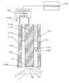
- FIG. 1illustrates an example system for applying energy to a cornea 2 of an eye 1 to generate heat and cause reshaping of the cornea.
- FIG. 1shows an applicator 110 with an electrical energy conducting element 111 that is operably connected to an electrical energy source 150 , for example, via conventional conducting cables.
- the electrical energy conducting element 111extends from a proximal end 110 A to a distal end 110 B of the applicator 110 .
- the electrical energy conducting element 111conducts electrical energy from the source 150 to the distal end 110 B to apply energy to the cornea 2 , which is positioned at the distal end 110 B.
- the electrical energy source 150may include a microwave oscillator for generating microwave energy.
- the oscillatormay operate at a microwave frequency range of 400 MHz to 3000 MHz, and more specifically at a frequency of around 915 MHz or 2450 MHz.
- microwavemay correspond to a frequency range from about 10 MHz to about 10 GHz.
- the electrical energy conducting element 111may include two microwave conductors, or electrodes, 111 A and 111 B, which extend from the proximal end 110 A to the distal end 110 B of the applicator 110 .
- the conductor 111 Amay be a substantially cylindrical outer conductor
- the conductor 111 Bmay be a substantially cylindrical inner conductor that is disposed in an inner passage extending through the outer conductor 111 A.
- the conductor 111 Amay have a substantially tubular shape.
- the outer conductor 111 A and inner conductor 111 Bmay be formed, for example, of aluminum, stainless steel, brass, copper, other metals, coated metals, metal-coated plastic, or any other suitable conductive material.
- a substantially annular gap 111 C of a selected distanceis defined between the conductors 111 A and 111 B.
- the annular gap 111 Cextends from the proximal end 110 A to the distal end 110 B.
- a dielectric material 111 Dmay be used in portions of the annular gap 111 C to separate the conductors 111 A and 111 B.
- the distance of the annular gap 111 C between conductors 111 A and 111 Bdetermines the penetration depth of microwave energy into the cornea 2 according to established microwave field theory.
- the microwave conducting element 111receives, at the proximal end 110 A, the electrical energy generated by the electrical energy source 150 , and directs microwave energy to the distal end 110 B, where the cornea 2 is positioned.
- the outer diameter of the inner conductor 111 Bis preferably larger than the pupil.
- the outer diameter of the inner conductor 111 Bmay be selected to achieve an appropriate change in corneal shape, i.e., keratometry, induced by the exposure to microwave energy.
- the inner diameter of the outer conductor 111 Amay be selected to achieve a desired gap between the conductors 111 A and 111 B.
- the outer diameter of the inner conductor 111 Branges from about 2 mm to about 10 mm while the inner diameter of the outer conductor 111 A ranges from about 2.1 mm to about 12 mm.
- the annular gap 111 Cmay be sufficiently small, e.g., in a range of about 0.1 mm to about 2.0 mm, to minimize exposure of the endothelial layer of the cornea (posterior surface) to elevated temperatures during the application of heat by the applicator 110 .
- the outer conductor 111 A and the inner conductor 111 Bmay be dimensioned to have very small diameters, so that the energy conducting element 111 essentially applies energy to the cornea 2 in a point, rather than in an annular shape.
- the energy conducting element 111may provide a pen-like device that shrinks corneal collagen at a selected area of very small diameter.
- such systemsemploy the energy conducting element 111 to shrink corneal collagen at a series of points and the combination of spot treatments results in the desired reshaping of the cornea 2 .
- a controller 140may be employed to selectively apply the energy any number of times according to any predetermined or calculated sequence.
- the controller 140may include a computer device to control the application of energy according to instructions provided via a computer-readable storage medium.
- the controller 140may include a monitor and keyboard, or other user interface devices for receiving instructions from an operator.
- each of the conductors 111 A and 111 Bmay be covered with an electrical insulator to minimize the concentration of electrical current in the area of contact between the corneal surface (epithelium) 2 A and the conductors 111 A and 111 B.
- the conductors 111 A and 111 B, or at least a portion thereofmay be coated with a material that can function both as an electrical insulator as well as a thermal conductor.
- a dielectric layer 110 Dmay be employed along the distal end 110 B of the applicator 110 to protect the cornea 2 from electrical conduction current that would otherwise flow into the cornea 2 via conductors 111 A and 111 B.
- the dielectric layer 110 Dis positioned between the conductors 111 A and 111 B and the cornea 2 .
- the dielectric layer 110 Dmay be sufficiently thin to minimize interference with microwave emissions and thick enough to prevent superficial deposition of electrical energy by flow of conduction current.
- the dielectric layer 110 Dmay be a biocompatible material deposited to a thickness of about 51. ⁇ m (0.002 inches).
- an interposing layersuch as the dielectric layer 110 D, may be employed between the conductors 111 A and 111 B and the cornea 2 .
- the interposing layerdoes not substantially interfere with the strength and penetration of the microwave radiation field in the cornea 2 . Moreover, the interposing layer does not prevent sufficient penetration of the microwave field and generation of a desired heating pattern in the cornea 2 .
- the dielectric materialmay be an elastic material, such as polyurethane or silastic. Alternatively, the dielectric material may be a nonelastic material, such as Teflon® or polyimides.
- the dielectric materialmay have a fixed dielectric constant or varying dielectric constant by mixing materials or doping the sheet, the variable dielectric being spatially distributed so that it may affect the microwave heating pattern in a customized way.
- the thermal conductivity of the materialmay have fixed thermal properties (thermal conductivity or specific heat), or may also vary spatially, through mixing of materials or doping, and thus provide a means to alter the heating pattern in a prescribed manner.
- Another approach for spatially changing the heating patternis to make the dielectric sheet material of variable thickness. The thicker region will heat less than the thinner region and provides a further means of spatial distribution of microwave heating. Embodiments employing dielectric layers of varying thickness are described further below.
- the applicator 110may also include a micro-controller coolant delivery system 112 .
- the micro-controlled coolant delivery system 112is in fluid communication with a coolant supply (not shown) and pulses of coolant, or cryogen, from the coolant supply may be applied toward the corneal surface 2 A before, during, and/or after energy is applied to the cornea 2 with the electrical energy source 150 and the electrical energy conducting element 111 .
- the applicator 110may be employed to apply coolant to selectively cool the surface 2 A of the cornea 2 positioned at the distal end 110 B.
- the coolant delivery system 112may have a nozzle structure 112 A with an opening 112 B directed toward the distal end 110 B.
- FIG. 1may illustrate one nozzle structure 112 A
- the coolant delivery system 112may include more than one nozzle structure 112 A arranged, for example, circumferentially within the annular gap 111 C.
- FIG. 1may illustrate the nozzle structure 112 A, other embodiments may employ other types of outlets or ports for delivering coolant to the surface 2 A or other areas of the eye 1 .
- the applicator 110may define a substantially enclosed assembly at the distal end 110 B, which is placed in contact with the corneal surface 2 A. As shown in FIG. 1 , this enclosed assembly may house the energy conducting element 111 and the coolant delivery element 112 .
- the dielectric layer 110 Dmay provide a membrane-like layer substantially enclosing the distal end 110 B of the applicator 110 . In this case, the coolant delivery system 112 applies coolant to the dielectric layer 110 D, rather than directly to the eye 1 .
- the controller 140may also be operably connected to the coolant delivery system 112 as well as the energy source 150 . As such, the controller 140 may be employed to determine the amount and timing of coolant delivered from the coolant delivery system 112 toward the corneal surface 2 A at the distal end 110 B. The controller 140 may be employed to selectively apply the heat and the coolant any number of times according to a predetermined or calculated sequence. For instance, the coolant may be applied to the corneal surface 2 A before, during, or after the application of heat to the cornea 2 , or any combination thereof.
- the coolant delivery system 112may employ a solenoid valve in combination with the delivery nozzle 112 A.
- a solenoid valveis an electromechanical valve for use with liquid or gas controlled by applying or stopping an electrical current through a coil of wire, thus changing the state of the valve.
- the controller 140may electronically control the actuation of the solenoid valve to deliver the coolant through the delivery nozzle 112 A to the corneal surface 2 A.
- other embodimentsmay employ other types of actuators or alternative techniques for delivering coolant through the delivery nozzle 112 A in place of a solenoid valve.
- the controller 140may be used to actuate the application of micro-controlled pulses of coolant to the corneal surface 2 A before the application of heat to the cornea 2 .
- a pulse, or a spurt, of coolantis applied to the corneal surface 2 A for a predetermined short period of time so that the cooling remains generally localized at the corneal surface 2 A while the temperature of deeper corneal collagen fibers 2 B remains substantially unchanged.
- the pulseis on the order of milliseconds and is less than 100 milliseconds.
- the delivery of the coolant to the corneal surfaceis controlled by the controller 140 and may be less than 1 millisecond.
- the time between the application of the coolant and the application of the heatis also controlled by the controller 140 and may also be less than 1 millisecond.
- the coolant pulsegenerally covers an area of the corneal surface 2 A that corresponds with the application of heat to the cornea 2 .
- the shape, size and disposition of the cooled regionmay be varied according to the application.
- localized delivery of coolant to the corneal surface 2 A before the application of heat to the cornea 2minimizes the resulting temperature at the corneal surface 2 A when the heat is applied, thereby minimizing any heat-induced injury to the corneal surface 2 A.
- the coolantreduces the temperature of the corneal surface 2 A, so that the maximum surface temperature achieved at the corneal surface 2 A during or immediately after heat exposure is also reduced by a similar magnitude when compared to a case where no coolant is applied prior to heat exposure.
- the temperature at the corneal surface 2 Arises during or immediately after heat exposure with persistent surface heating resulting from a slow dissipation of heat trapped near the surface-air interface.
- a delayed thermal wavemay arrive at the corneal surface 2 A after exposure as the heat generated in the corneal areas 2 B below the surface 2 A diffuses toward the cooled surface 2 A.
- the heat transfer from the corneal surface 2 A to the surrounding airis likely to be insignificant, because air is an excellent thermal insulator.
- heat diffusing away from the areas 2 B beneath the corneal surface 2 Abuilds up near the corneal surface 2 A and produces an elevated surface temperature that may persist after the application of heat.
- the heat that builds up near the corneal surface 2 Amay eventually dissipate through thermal diffusion and cooling via blood perfusion, such dissipation may take several seconds.
- embodimentsmay employ not only a pulse of coolant immediately prior to heat exposure, but also one or more pulses of coolant thereafter. Accordingly, in further operation of the embodiment of FIG. 1 , the controller 140 may also be used to apply micro-controlled pulses of coolant during or after the applicator 110 applies heat to the cornea 2 , or any combination thereof. This application of coolant rapidly removes heat which diffuses from the mid-depth corneal region 2 B to the corneal surface 2 A.
- the coolant delivery system 112delivers the pulse of coolant to the corneal surface 2 A
- the coolant on the corneal surface 2 Adraws heat from the surface 2 A, causing the coolant to evaporate.
- coolant applied to the surface 2 Acreates a heat sink at the surface 2 A, resulting in the removal of heat before, during, and after the application of heat to the cornea 2 .
- the heat sinkpersists for as long as the liquid cryogen remains on the surface 2 A.
- the heat sinkcan rapidly remove the trapped heat at the surface 2 A without cooling the collagen fibers in the region 2 B.
- a factor in drawing heat out of the cornea 2is the temperature gradient that is established near the surface 2 A. The steeper the gradient, the faster a given quantity of heat is withdrawn.
- the application of the coolantattempts to produce a large surface temperature drop as quickly as possible.
- the amount and duration of coolant applied to the corneal surface 2 Aaffects the amount of heat that passes into and remains in the region underlying the corneal surface 2 A.
- controlling the amount and duration of the coolingprovides a way to control the depth of corneal heating, promoting sufficient heating of targeted collagen fibers in the mid-depth region 2 B while minimizing the application of heat to regions outside the targeted collagen fibers.
- dynamic cooling of the corneal surface 2 Amay be optimized by controlling: (1) the duration of the cooling pulse(s); (2) the duty cycle of multiple pulses; (3) the quantity of coolant deposited on the corneal surface 2 A so that the effect of evaporative cooling can be maximized; and (4) timing of dynamic cooling relative to heat application.
- a single pulse timingmay include applying a 80 ms heat pulse and a 40 ms cooling pulse at the beginning, middle, or end of the heating pulse.
- multiple cooling pulsesmay be applied according to a pattern of 10 ms ON and 10 ms OFF, with four of these pulses giving a total of 40 ms of cooling, but timed differently.
- the coolantmay be the cryogen tetrafluoroethane, C 2 H 2 F 4 , which has a boiling point of about ⁇ 26.5° C. and which is an environmentally compatible, nontoxic, nonflammable freon substitute.
- the coolantmay be a fluorocarbon refrigerant, e.g., R134.
- the coolant pulse released from the coolant delivery system 112may include droplets of the cryogen cooled by evaporation as well as mist formed by adiabatic expansion of vapor.
- the coolantmay be selected so that it provides one or more of the following: (1) sufficient adhesion to maintain good surface contact with the corneal surface 2 A; (2) a high thermal conductivity so the corneal surface 2 A may be cooled very rapidly prior to heat application; (3) a low boiling point to establish a large temperature gradient at the surface; (4) a high latent heat of vaporization to sustain evaporative cooling of the corneal surface 2 A; and (5) no adverse health or environmental effects.
- tetrafluoroethanemay satisfy the criteria above, it is understood that embodiments of the present invention are not limited to a particular cryogen and that other coolants, such as liquid nitrogen, argon, or the like, may be employed to achieve similar results.
- the coolantdoes not have to be a liquid, but in some embodiments, may have a gas form.
- the pulse of coolantmay be a pulse of cooling gas.
- the coolantmay be nitrogen (N 2 ) gas or carbon dioxide (CO 2 ) gas.
- the controller 140may be employed to selectively apply the heat and the coolant pulses any number of times according to any predetermined or calculated sequence.
- the heat and the pulses of coolantmay be applied for any length of time.
- the magnitude of heat being appliedmay also be varied. Adjusting such parameters for the application of heat and pulses of coolant determines the extent of changes that are brought about within the cornea 2 .
- embodiments of the present inventionattempt to limit the changes in the cornea 2 to an appropriate amount of shrinkage of selected collagen fibers.
- the microwave energymay be applied with low power (of the order of 40 W) and in long pulse lengths (of the order of one second).
- microwave energymay be applied in short pulses.
- the microwave energymay be applied in pulses having a higher power in the range of 300 W to 3 kW and a pulse duration in the range of about 2 milliseconds to about one second.
- a first pulse of coolantis delivered to reduce the temperature of the corneal surface 2 A; a high power pulse of microwave energy is then applied to generate heat within selected areas of collagen fibers in a mid-depth region 2 B; and a second pulse of coolant is delivered in sequence to end further heating effect and “set” the corneal changes that are caused by the energy pulse.
- the application of energy pulses and coolant pulses in this manneradvantageously reduces the amount to heat diffusion that occurs and minimizes the unwanted impact of heating and resulting healing processes on other eye structures, such as the corneal endothelium.
- this techniquepromotes more permanent and stable change of the shape of the cornea 2 produced by the heat.
- the application of high powered energy in short pulseshas been described with respect to the delivery of microwave energy, a similar technique may be applied with other types of energy, such as optical energy or electrical energy with radio frequency (RF) wavelengths described further below.
- RFradio frequency
- FIG. 1The system of FIG. 1 is provided for illustrative purposes only, and other systems may be employed to apply energy to cause reshaping of the cornea.
- Other systemsare described, for example, in U.S. patent application Ser. No. 12/208,963, filed Sep. 11, 2008, which is a continuation-in-part application of U.S. patent application Ser. No. 11/898,189, filed on Sep. 10, 2007, the contents of these applications being entirely incorporated herein by reference.
- the distal end 110 B of the applicator 110 as shown in FIG. 1is positioned on or near the corneal surface 2 A.
- the applicator 110makes direct contact with the corneal surface 2 A.
- such direct contactpositions the conductors 111 A and 111 B at the corneal surface 2 A, though a thin interposing dielectric layer 110 D may be disposed between the conductors 111 A and 111 B and the corneal surface 2 A. Accordingly, direct contact helps ensure that the pattern of microwave heating in the corneal tissue has substantially the same shape and dimension as the gap 111 C between the two microwave conductors 111 A and 111 B.
- the corneal surface 2 APrior to positioning of the applicator 110 in contact with the corneal surface 2 A, the corneal surface 2 A may be scanned to make a topographical map showing the shape and curvature of the surface of the cornea. Then, with the conductors 111 A and 111 B positioned flush with the corneal surface 2 A, the treatment may apply durations of microwave pulses to generate heat and reshape collagen. The treatment may also apply coolant pulses to protect the corneal surface. In one aspect, the treatment attempts to shrink the collagen in the cornea 2 and form a precisely controlled annular lesion in approximately the upper 150 ⁇ m of the stroma. The microwave treatment raises the temperature of an annulus, just below the surface of the cornea, to a temperature in the range of approximately 60 to 75° C.
- the systemcools the surface of the cornea during treatment to isolate and protect the epithelium and Bowman's membrane from microwave heating.
- the treatmentis noninvasive, as there is no cutting or penetration of the eye.
- the applicator 110predictably flattens the central cornea to achieve mild-to-moderate myopic correction ( ⁇ 0.5 to ⁇ 3.5 diopters, D) without compromising the biomechanical integrity of the cornea.
- embodiments according to aspects of the present inventionmay apply microwave energy emitted from the applicator 110 in a substantially annular pattern around the pupil to shrink stromal collagen and modify the dioptric power of the cornea, while a cooling system acts on the corneal surface to minimize thermal damage to the epithelium.
- electric field linesform a fringing pattern that extends into the corneal stroma to a depth determined by the applied power and applicator geometry. This electric field causes the polar water molecules to align themselves with the field; the rapid reversal of the sinusoidally-varying field causes frictional heating by these molecules as they rotate in place. This effect does not require a conduction current to flow through a point of electrical contact between a conductor and tissue; heating is caused by a displacement current.
- the applicator 110 of FIG. 1may apply energy according to substantially annular patterns defined by the outer conductor 111 A and inner conductor 111 B
- other embodimentsmay apply energy to an eye in asymmetrical and/or irregular patterns.
- Such applicationscan correct eye disorders such as astigmatism.
- the energy conducting element 111may provide a pen-like device that shrinks corneal collagen at a selected spot of very small diameter.
- the combination of spotsmay be applied to define an asymmetric and/or irregular pattern. Further description of systems for reshaping of the cornea according to asymmetric and/or irregular patterns are provided in U.S.
- FIGS. 2A-Dillustrate an example of the effect of applying heat to corneal tissue with a system for applying heat, such as the system illustrated in FIG. 1 .
- FIGS. 2A and 2Billustrate high resolution images of cornea 2 after heat has been applied.
- a lesion 4extends from the corneal surface 2 A to a mid-depth region 2 B in the corneal stroma 2 C.
- the lesion 4is the result of changes in corneal structure induced by the application of heat as described above. These changes in structure result in an overall reshaping of the cornea 2 . It is noted that the application of heat, however, has not resulted in any heat-related damage to the corneal tissue.
- FIGS. 2A and 2Billustrate histology images in which the tissue shown in FIGS. 2A and 2B has been stained to highlight the structural changes induced by the heat.
- FIGS. 2C and 2Dillustrate histology images in which the tissue shown in FIGS. 2A and 2B has been stained to highlight the structural changes induced by the heat.
- the difference between the structure of collagen fibrils in the mid-depth region 2 B where heat has penetrated and the structure of collagen fibrils outside the region 2 Bis clearly visible.
- the collagen fibrils outside the region 2 Bremain generally unaffected by the application of heat, while the collagen fibrils inside the region 2 B have been rearranged and formed new bonds to create completely different structures.
- unlike processes, such as orthokeratologywhich compress areas of the cornea to reshape the cornea via mechanical deformation, the collagen fibrils in the region 2 B are in an entirely new state.
- a dielectric layer 110 Dmay be employed along the distal end 110 B of the applicator 110 and positioned between the energy conducting element 111 and the cornea 2 .
- the dielectric materialdoes not have to be applied directly to the outer conductor 111 A and/or the inner conductor 111 B.
- a removable sheath, or covering, 120may be fitted over the distal end 110 B of the energy conducting element 111 , where the sheath 120 includes a dielectric layer 122 at a contact surface 121 .
- the sheath 120includes a wall 123 , such as, but not limited to, a flexible film material, that defines the contact surface 121 .
- the contact surface 121is aligned with the distal end 110 B of the applicator 110 .
- the contact surface 121is disposed between the applicator 110 and the eye 1 .
- the contact surface 121rather than the applicator 110 , comes into direct contact with the eye 1 .
- the contact surface 121provides an interface between the patient and the therapy system.
- the dielectric layer 122When the sheath 120 is properly fitted, the dielectric layer 122 is disposed in proper relation to the outer conductor 111 A and the inner conductor 111 B. As described previously, the dielectric layer 122 protects the cornea 2 from electrical conduction current that would otherwise flow into the eye 1 via conductors 111 A and 111 B.
- the dielectric layer 122may be formed from an elastic material, such as polyurethane or silastic. Alternatively, the dielectric layer 122 may be formed from a nonelastic material, such as Teflon® or polyimides. In some embodiments, the entire sheath 120 may be formed from the dielectric material. In other embodiments, the dielectric material is employed only at the contact surface 121 of the sheath 120 to form the dielectric layer 122 , while the rest of the sheath 120 is formed from other materials.
- the sheath 120encloses the distal end 110 B of the applicator 110 .
- the coolant delivery system 112applies coolant directly to the contact surface 121 , rather than directly to the eye.
- the delivery of coolantsufficiently cools the surface of the cornea during treatment to isolate and protect the epithelium and Bowman's membrane from microwave heating.
- the eye 1is not directly exposed to the coolant material.
- the contact surface 121provides a protective layer over the eye 1 during the operation of the applicator 110 .
- the sheath 120may be removed from the applicator 110 and replaced after each use.
- the disposable nature of the sheath 120promotes hygienic use of the applicator 110 , as the direct contact with the patient's eye can be limited to the contact surface 121 . Replacing the sheath 120 after each use helps to ensure that there is no cross-contact between patients.
- the sheath 120may have a substantially cup-like shape that provides a fit over the distal end 110 B of the applicator 110 .
- the wall 123defines a cavity 124 .
- the cavity 124receives the distal end 110 B of the applicator 110 through an opening 125 .
- the inner surface of the wall 123 within the cavity 124may be textured or otherwise treated, e.g., with a non-permanent adhesive, to enhance frictional contact and provide more secure engagement between the sheath 120 and the applicator 110 .
- FIG. 4Balso shows that the contact surface 121 of the sheath 120 may be concave, i.e., curves into the cavity 122 .
- the concave shape of the contact surface 121minimizes any applanation that the sheath 120 may cause when applied against the eye 1 .
- the contact surface 121is not biased outwardly to apply any unwanted additional pressure against the eye 1 .
- the concave shapealso promotes more effective contact between the contact surface 121 and the distal end 110 B of the applicator 110 .
- the dielectric layer 122is properly disposed along the distal end 110 B of the applicator 110 , and the delivery of energy to the eye 1 is not affected by any gaps or other irregularities between the dielectric layer 122 and the applicator 110 .
- FIG. 5illustrates a sheath 120 that is supported by a more rigid carrier 130 .
- the carrier 130facilitates manual handling and positioning of the sheath 120 .
- the carrier 130is a molded thermoplastic polyurethane structure
- the sheath 120is a polyurethane film that is thermally bonded to the carrier 130 .
- the carrier 130engages the periphery of the applicator 110 to provide a tight press-fit and securely position the sheath 120 over the distal end 110 B of the applicator 110 .
- the tight press-fitminimizes any relative movement between the sheath 120 and the applicator 110 .
- the carrier 130includes a collar 132 and a plurality of ribs 134 .
- the collar 132 and the ribs 134provide the substantially cup-like shape for the sheath 120 .
- the collar 132maintains the shape, e.g., circular shape, of the opening 125 to the cavity 124 .
- the collar 132facilitates the insertion of the applicator 110 into the cavity 124 .
- the ribs 134are spaced along the circumference of the collar 132 and extend toward the contact surface 121 of the sheath 120 .
- the ribs 134support the sides of the sheath 120 .
- FIG. 5also shows that the ribs 134 extend radially inward, i.e., angle into the cavity 124 , as they extend away from the collar 132 .
- the diameter across the cavity 124reduces as the ribs 134 extend away from the collar 132 .
- the ribs 134engage the applicator 110 with greater pressure. This pressure provides a tighter fit between the carrier 130 and the applicator 110 .
- the sheath 120is supported against the applicator 110 .
- FIG. 5may illustrate a sheath 120 assembled with a separate carrier 130
- supporting structuresmay be integral with the sheath 120 .
- structures similar to the collar 132 and the ribs 134may be formed by increasing the thickness of wall 123 at selected sections of the sheath 120 .
- the thicker sectionsmay provide sufficient rigidity to facilitate handling of the sheath 120 and to fit the sheath 120 securely to the applicator 110 .
- materials of greater rigiditymay be incorporated into the walls 123 of the sheath 120 .
- supporting structures for the sheath 120are not limited to the specific shapes and configurations described herein.
- other embodimentsmay employ other structures or mechanisms that removably fit a desired dielectric layer at the distal end of an applicator.
- the sheath 120may have a substantially uniform thickness.
- the filmmay be approximately 50 ⁇ m in thickness.
- the thickness of the sheath 120may vary.
- the dielectric layer 122 along the contact surface 121may have varying thickness.
- the dielectric layer 122includes a first section 122 A and second section 122 B, where the second section 122 B is thicker than the section 122 A.
- varying the thickness of a dielectric layerprovides a technique for determining the pattern of energy delivered to the cornea.
- a dielectric layerresults in an impedance that affects the delivery of energy through the dielectric layer.
- a thicker layer of a given dielectric materialprovides greater impedance.
- a dielectric material having sufficient thicknesscan minimize conductivity.
- thick sections of dielectric materialmay be employed along the contact surface 121 to define a selected pattern for delivering energy through the dielectric layer 122 .
- the actual dimensions of the thick sectionsdepend on the material from which the sections are formed. Different materials may require the application of different thicknesses to achieve a given impedance.
- a polyurethane film of 50. ⁇ mdoes not change the annular pattern defined by the conductors 111 A and 111 B for the delivery of energy from the applicator 110 .
- the pattern of energycould be modified from the annular pattern.
- another materialcould be employed along the dielectric layer 122 to provide a section of sufficiently high impedance.
- FIG. 6Aillustrates a sheath 220 that may be applied to the applicator 110 .
- the sheath 220includes a dielectric layer 222 of varying thickness on the contact surface 221 .
- the dielectric layer 222includes thick dielectric sections 222 A of high impedance and a thin dielectric section 222 B of lower impedance.
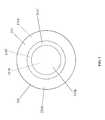
- FIG. 6Bshows the dielectric layer 222 at the contact surface 221 of the sheath 220 .
- the dotted lines in FIG. 6Bidentify the outer conductor 111 A, the inner conductor 111 B, and the gap 111 C disposed within the cavity 224 .
- the annular profiles of the outer conductor 111 A and the gap 111 Care concentric with the circular profile of the inner conductor 111 B.
- the two thick dielectric sections 222 Acorrespond to opposing sections of the outer conductor 111 A. Meanwhile, the thin dielectric section 222 B forms the remainder of the dielectric layer 222 . Due to the high impedance of the thick dielectric sections 222 A, the energy from the energy conducting element 111 is not delivered through the dielectric layer 222 in an annular pattern. In particular, the thick dielectric sections 222 A have the effect of segmenting the outer conductor 111 A into C-shaped outer conductors, each of which provides a corresponding pattern for energy delivery. The thick dielectric sections 222 A effectively prevent the corresponding sections of the outer conductor 111 A from forming an electrode pair with the inner conductor 111 B and from contributing to the pattern of energy delivered to the eye.
- thick sections of the dielectric layer 222may be aligned with sections of the inner conductor 111 B. In this case, these thick sections effectively prevent the corresponding sections of the inner conductor 111 B from forming an electrode pair with the outer conductor 111 A.
- FIGS. 6A-Bshows that the thickness of the dielectric layer on a sheath may be varied to change the pattern of energy delivery to the eye.
- the exampleillustrates that the pattern can be non-annular.
- the dielectric layercan also be configured to produce an asymmetric pattern.
- an asymmetric patterncan be achieved by implementing only one of the thick dielectric sections 222 A.
- the sheathmay be employed to deliver energy to the cornea in an irregularly shaped, e.g., asymmetric and/or non-annular, pattern
- embodiments according to aspects of the present inventionmay be employed to treat an eye disorder, such as astigmatism.
- a sheath that provides a dielectric layer with an asymmetric and/or irregular pattern to treat astigmatismcan be more easily reoriented with respect to the applicator or the eye to accommodate the axis of astigmatism.
- Further examples of asymmetric and/or irregular patterns that can be produced with the sheath described hereinare provided in U.S. patent application Ser. No. 12/113,672, filed May 1, 2008, the contents of which are entirely incorporated herein by reference.
- the sheathcan provide a variety of configurations for the dielectric layer, a single energy applicator may be employed with different sheaths to deliver energy to the eye according to different patterns.
- the sheathmay be employed to customize a standard energy applicator and eliminate the need for multiple applicators with fixed configurations and/or fixed dimensions.
- Embodiments according to aspects of the present inventionmay employ a variety of materials and/or a variety of thicknesses to configure the contact surface of the sheath. Indeed, as shown in FIG. 7 , a contact surface 321 of a sheath 320 does not include an entire layer of one or more dielectric materials. Rather, the contact surface 321 of the sheath 320 includes one or more conductive materials in addition to one or more dielectric materials.
- the contact surface 321may include a layer 321 A that aligns at least partially with the outer conductor 111 A, a layer 321 B that aligns at least partially with the inner conductor 111 B, and a layer 321 C that aligns at least partially with the gap 111 C between the conductors 111 A and 111 B.
- the layersmay be concentric but are not necessarily so. In addition, the layers do not have to coincide completely with features of the energy conducting element.
- one or more conductive materialsform the layers 321 A and 321 B, while one or more dielectric materials form the layer 321 C.
- the contact surface 321includes two conductive layers separated by a dielectric layer.
- one or more conductive materialsmay form the layer 321 A, while one or more dielectric materials form the layers 321 B and 321 C.
- a conductive layeris aligned at least partially with the outer electrode 111 A, while a dielectric layer covers the remainder of the contact surface 321 .
- one or more conductive materialsmay form the layer 321 B, while one or more dielectric materials form the layers 321 A and 321 C.
- a conductive layeris aligned at least partially with the outer electrode 111 B, while a dielectric layer covers the remainder of the contact surface 321 .
- the use of dielectric materials and conductive materials for the contact surfaceare not limited to these examples.
- any one of the layers 321 A, 321 B, and 321 Cmay include both conductive and dielectric materials to achieve a particular pattern. It is noted, however, that a conductive path should not extend from the layer 321 A and 321 B, so that the outer conductor 111 A and the inner conductor 111 B remain electrically separated.
- the sheath 320allows the appropriate lesion to be formed in the corneal tissue, while also providing an intermediate layer that allows coolant to be applied to the eye without direct contact.
Landscapes
- Health & Medical Sciences (AREA)
- Surgery (AREA)
- Engineering & Computer Science (AREA)
- Life Sciences & Earth Sciences (AREA)
- Biomedical Technology (AREA)
- Molecular Biology (AREA)
- Nuclear Medicine, Radiotherapy & Molecular Imaging (AREA)
- Plasma & Fusion (AREA)
- Physics & Mathematics (AREA)
- Heart & Thoracic Surgery (AREA)
- Medical Informatics (AREA)
- Otolaryngology (AREA)
- Animal Behavior & Ethology (AREA)
- General Health & Medical Sciences (AREA)
- Public Health (AREA)
- Veterinary Medicine (AREA)
- Thermotherapy And Cooling Therapy Devices (AREA)
- Surgical Instruments (AREA)
Abstract
Description
Claims (44)
Priority Applications (1)
| Application Number | Priority Date | Filing Date | Title |
|---|---|---|---|
| US12/572,019US8460278B2 (en) | 2008-10-01 | 2009-10-01 | Eye therapy system |
Applications Claiming Priority (2)
| Application Number | Priority Date | Filing Date | Title |
|---|---|---|---|
| US10182008P | 2008-10-01 | 2008-10-01 | |
| US12/572,019US8460278B2 (en) | 2008-10-01 | 2009-10-01 | Eye therapy system |
Publications (2)
| Publication Number | Publication Date |
|---|---|
| US20100094280A1 US20100094280A1 (en) | 2010-04-15 |
| US8460278B2true US8460278B2 (en) | 2013-06-11 |
Family
ID=42073886
Family Applications (1)
| Application Number | Title | Priority Date | Filing Date |
|---|---|---|---|
| US12/572,019Expired - Fee RelatedUS8460278B2 (en) | 2008-10-01 | 2009-10-01 | Eye therapy system |
Country Status (4)
| Country | Link |
|---|---|
| US (1) | US8460278B2 (en) |
| EP (1) | EP2346429A4 (en) |
| JP (1) | JP2012504472A (en) |
| WO (1) | WO2010039979A1 (en) |
Cited By (5)
| Publication number | Priority date | Publication date | Assignee | Title |
|---|---|---|---|---|
| US10575986B2 (en) | 2012-03-29 | 2020-03-03 | Cxl Ophthalmics, Llc | Ophthalmic treatment solution delivery devices and delivery augmentation methods |
| US10729716B2 (en) | 2012-03-29 | 2020-08-04 | Cxl Ophthalmics, Llc | Compositions and methods for treating or preventing diseases associated with oxidative stress |
| US10932864B2 (en) | 2018-11-28 | 2021-03-02 | Rxsight, Inc. | Tracking-based illumination control system |
| US11013593B2 (en) | 2018-12-02 | 2021-05-25 | Rxsight, Inc. | Light adjustable lens tracking system and method |
| US11033429B2 (en) | 2010-09-30 | 2021-06-15 | Cxl Ophthalmics, Llc | Ophthalmic treatment device, system, and method of use |
Families Citing this family (21)
| Publication number | Priority date | Publication date | Assignee | Title |
|---|---|---|---|---|
| US8202272B2 (en) | 2007-07-19 | 2012-06-19 | Avedro, Inc. | Eye therapy system |
| US8992516B2 (en)* | 2007-07-19 | 2015-03-31 | Avedro, Inc. | Eye therapy system |
| US20090187173A1 (en)* | 2008-01-23 | 2009-07-23 | David Muller | System and method for reshaping an eye feature |
| JP2012508087A (en)* | 2008-11-11 | 2012-04-05 | アヴェドロ・インコーポレーテッド | Eye treatment system |
| WO2010115121A1 (en)* | 2009-04-02 | 2010-10-07 | Avedro, Inc. | Eye therapy system |
| EP2413832A1 (en)* | 2009-04-02 | 2012-02-08 | Avedro, INC. | Eye therapy system |
| US20100280509A1 (en)* | 2009-04-02 | 2010-11-04 | Avedro, Inc. | Eye Therapy System |
| US9821159B2 (en) | 2010-11-16 | 2017-11-21 | The Board Of Trustees Of The Leland Stanford Junior University | Stimulation devices and methods |
| JP2013542838A (en) | 2010-11-16 | 2013-11-28 | ザ ボード オブ トラスティーズ オブ ザ レランド スタンフォード ジュニア ユニバーシティー | System and method for treating dry eye |
| WO2014138709A1 (en) | 2013-03-08 | 2014-09-12 | Oculeve, Inc. | Devices and methods for treating dry eye in animals |
| WO2014165124A1 (en) | 2013-03-12 | 2014-10-09 | Oculeve, Inc. | Implant delivery devices, systems, and methods |
| NZ704579A (en) | 2013-04-19 | 2018-10-26 | Oculeve Inc | Nasal stimulation devices and methods |
| ES2812752T3 (en) | 2014-02-25 | 2021-03-18 | Oculeve Inc | Polymer formulations for nasolacrimal stimulation |
| AU2015292278B2 (en) | 2014-07-25 | 2020-04-09 | Oculeve, Inc. | Stimulation patterns for treating dry eye |
| CA2965363A1 (en) | 2014-10-22 | 2016-04-28 | Oculeve, Inc. | Implantable nasal stimulator systems and methods |
| EP3209372B1 (en) | 2014-10-22 | 2020-07-15 | Oculeve, Inc. | Stimulation devices for treating dry eye |
| WO2016065211A1 (en) | 2014-10-22 | 2016-04-28 | Oculeve, Inc. | Contact lens for increasing tear production |
| US10426958B2 (en) | 2015-12-04 | 2019-10-01 | Oculeve, Inc. | Intranasal stimulation for enhanced release of ocular mucins and other tear proteins |
| US10252048B2 (en) | 2016-02-19 | 2019-04-09 | Oculeve, Inc. | Nasal stimulation for rhinitis, nasal congestion, and ocular allergies |
| AU2017260237A1 (en) | 2016-05-02 | 2018-11-22 | Oculeve, Inc. | Intranasal stimulation for treatment of meibomian gland disease and blepharitis |
| WO2018102535A1 (en) | 2016-12-02 | 2018-06-07 | Oculeve, Inc. | Apparatus and method for dry eye forecast and treatment recommendation |
Citations (110)
| Publication number | Priority date | Publication date | Assignee | Title |
|---|---|---|---|---|
| US3776230A (en) | 1973-04-18 | 1973-12-04 | C Neefe | Method of rapidly reshaping the cornea to eliminate refractive errors |
| US4326529A (en) | 1978-05-26 | 1982-04-27 | The United States Of America As Represented By The United States Department Of Energy | Corneal-shaping electrode |
| US4381007A (en)* | 1981-04-30 | 1983-04-26 | The United States Of America As Represented By The United States Department Of Energy | Multipolar corneal-shaping electrode with flexible removable skirt |
| US4490022A (en) | 1982-01-04 | 1984-12-25 | Reynolds Alvin E | Apparatus for corneal corrective techniques |
| US4712543A (en) | 1982-01-20 | 1987-12-15 | Baron Neville A | Process for recurving the cornea of an eye |
| US4743725A (en) | 1985-12-05 | 1988-05-10 | Skandinavisk Torkteknik Ab | Coaxial line microwave heating applicator with asymmetrical radiation pattern |
| US4796623A (en) | 1987-07-20 | 1989-01-10 | The Cooper Companies, Inc. | Corneal vacuum trephine system |
| US4805616A (en) | 1980-12-08 | 1989-02-21 | Pao David S C | Bipolar probes for ophthalmic surgery and methods of performing anterior capsulotomy |
| US4881543A (en) | 1988-06-28 | 1989-11-21 | Massachusetts Institute Of Technology | Combined microwave heating and surface cooling of the cornea |
| US4891043A (en) | 1987-05-28 | 1990-01-02 | Board Of Trustees Of The University Of Illinois | System for selective release of liposome encapsulated material via laser radiation |
| US4994058A (en) | 1986-03-19 | 1991-02-19 | Summit Technology, Inc. | Surface shaping using lasers |
| US5019074A (en)* | 1987-03-09 | 1991-05-28 | Summit Technology, Inc. | Laser reprofiling system employing an erodable mask |
| US5080660A (en)* | 1990-05-11 | 1992-01-14 | Applied Urology, Inc. | Electrosurgical electrode |
| US5103005A (en) | 1989-07-21 | 1992-04-07 | Coors Biotech, Inc. | Method for recovery of riboflavin |
| US5171254A (en) | 1991-11-19 | 1992-12-15 | Sher Neal A | Eye fixation device |
| US5281211A (en) | 1989-06-07 | 1994-01-25 | University Of Miami, School Of Medicine, Dept. Of Ophthalmology | Noncontact laser microsurgical apparatus |
| US5332802A (en) | 1988-02-18 | 1994-07-26 | Autogenesis Technologies, Inc. | Human collagen processing and autoimplant use |
| US5370644A (en) | 1988-11-25 | 1994-12-06 | Sensor Electronics, Inc. | Radiofrequency ablation catheter |
| US5437658A (en) | 1992-10-07 | 1995-08-01 | Summit Technology, Incorporated | Method and system for laser thermokeratoplasty of the cornea |
| US5461212A (en) | 1993-06-04 | 1995-10-24 | Summit Technology, Inc. | Astigmatic laser ablation of surfaces |
| US5490849A (en) | 1990-07-13 | 1996-02-13 | Smith; Robert F. | Uniform-radiation caustic surface for photoablation |
| US5586134A (en) | 1992-11-13 | 1996-12-17 | Cymer Laser Technologies | Excimer laser |
| US5618284A (en) | 1985-09-27 | 1997-04-08 | Sunrise Technologies | Collagen treatment apparatus |
| US5624456A (en) | 1996-02-07 | 1997-04-29 | Hellenkamp; Johann F. | Automatic surgical device for cutting a cornea |
| US5634921A (en) | 1993-08-23 | 1997-06-03 | Hood; Larry | Method and apparatus for modifications of visual acuity by thermal means |
| US5658278A (en) | 1992-12-01 | 1997-08-19 | Cardiac Pathways, Inc. | Catheter for RF ablation with cooled electrode and method |
| US5695448A (en)* | 1994-08-29 | 1997-12-09 | Olympus Optical Co., Ltd. | Endoscopic sheath |
| US5766171A (en) | 1994-02-09 | 1998-06-16 | Keravision, Inc. | Electrosurgical procedure for the treatment of the cornea |
| US5779696A (en) | 1990-07-23 | 1998-07-14 | Sunrise Technologies International, Inc. | Method and apparatus for performing corneal reshaping to correct ocular refractive errors |
| US5814040A (en) | 1994-04-05 | 1998-09-29 | The Regents Of The University Of California | Apparatus and method for dynamic cooling of biological tissues for thermal mediated surgery |
| US5830139A (en) | 1996-09-04 | 1998-11-03 | Abreu; Marcio M. | Tonometer system for measuring intraocular pressure by applanation and/or indentation |
| US5873901A (en) | 1995-06-30 | 1999-02-23 | Space Vacuum Epitaxy Center University Of Houston | Treating retinal damage by implanting thin film optical detectors |
| US5885275A (en) | 1998-01-15 | 1999-03-23 | Diomed, Inc. | Medical spacing guide |
| US5910110A (en) | 1995-06-07 | 1999-06-08 | Mentor Ophthalmics, Inc. | Controlling pressure in the eye during surgery |
| US5919222A (en) | 1998-01-06 | 1999-07-06 | Medtronic Inc. | Adjustable medical electrode lead |
| US5941834A (en)* | 1997-03-17 | 1999-08-24 | Polartechnics Limited | Sheath for a side view probe |
| US6033396A (en) | 1995-11-06 | 2000-03-07 | Huang; David | Apparatus and method for performing laser thermal keratoplasty with minimized regression |
| US6053909A (en) | 1998-03-27 | 2000-04-25 | Shadduck; John H. | Ionothermal delivery system and technique for medical procedures |
| US6104959A (en) | 1997-07-31 | 2000-08-15 | Microwave Medical Corp. | Method and apparatus for treating subcutaneous histological features |
| US6139876A (en) | 1995-04-26 | 2000-10-31 | Jozsef Ladanyi | Gel with increased oxygen content |
| US6149646A (en) | 1999-02-02 | 2000-11-21 | Linvatec Corporation | Monopolar tissue ablator |
| WO2000074648A2 (en) | 1999-06-04 | 2000-12-14 | Sunrise Technologies International, Inc. | Prevention of regression in refractive keratoplasty |
| US6161544A (en) | 1998-01-28 | 2000-12-19 | Keratoform, Inc. | Methods for accelerated orthokeratology |
| US6162210A (en) | 1998-08-06 | 2000-12-19 | Shadduck; John H. | Laser mediated treatments for presbyopia and hyperopia |
| US6293938B1 (en) | 1994-04-08 | 2001-09-25 | Summit Technology, Inc. | Photo-refractive keratectomy |
| US6319273B1 (en) | 1999-12-16 | 2001-11-20 | Light Sciences Corporation | Illuminating device for treating eye disease |
| US6325792B1 (en) | 1991-11-06 | 2001-12-04 | Casimir A. Swinger | Ophthalmic surgical laser and method |
| US20020002369A1 (en) | 1993-08-23 | 2002-01-03 | Hood Larry L. | Method and apparatus for modifying visual acuity by moving a focal point of energy within a cornea |
| US6342053B1 (en) | 1990-07-23 | 2002-01-29 | Laser Biotech, Inc. | Apparatus for cornea reshaping |
| US20020013579A1 (en) | 1997-10-03 | 2002-01-31 | Thomas A. Silvestrini | Rotating electrosurgical blade for corneal reshaping |
| US6402739B1 (en) | 1998-12-08 | 2002-06-11 | Y-Beam Technologies, Inc. | Energy application with cooling |
| US20020077699A1 (en) | 2000-09-08 | 2002-06-20 | Luigi Olivieri | Apparatus and method for corneal surgery |
| US6413255B1 (en) | 1999-03-09 | 2002-07-02 | Thermage, Inc. | Apparatus and method for treatment of tissue |
| US20020099363A1 (en) | 2001-01-23 | 2002-07-25 | Woodward Benjamin W. | Radiation treatment system and method of using same |
| US20020164379A1 (en) | 2000-06-29 | 2002-11-07 | Toru Nishihara | Oxygen-containing ophthalmic composition |
| US20030018255A1 (en) | 1997-10-31 | 2003-01-23 | Martin Roy W. | Method and apparatus for medical procedures using high-intensity focused ultrasound |
| US6520956B1 (en) | 1995-11-06 | 2003-02-18 | David Huang | Apparatus and method for performing laser thermal keratoplasty with minimized regression |
| US20030097130A1 (en) | 1997-09-04 | 2003-05-22 | Gerhard Muller | Electrode arrangement for electrothermal treatment of human or animal bodies |
| US6617963B1 (en) | 1999-02-26 | 2003-09-09 | Sri International | Event-recording devices with identification codes |
| US20030175259A1 (en) | 1998-03-09 | 2003-09-18 | Hamper Karageozian | Use of corneal hardening agents in enzymeorthokeratology |
| US20030216728A1 (en) | 1996-01-05 | 2003-11-20 | Stern Roger A. | RF electrode assembly for handpiece |
| US20040001821A1 (en) | 2000-10-13 | 2004-01-01 | Silver David M. | Plasminogen activator to prevent corneal and subepithelial haze after laser vision correction surgery |
| US20040111086A1 (en) | 2002-12-09 | 2004-06-10 | Trembly B. Stuart | Feedback control of thermokeratoplasty treatments |
| US6749604B1 (en) | 1993-05-10 | 2004-06-15 | Arthrocare Corporation | Electrosurgical instrument with axially-spaced electrodes |
| US20040199158A1 (en) | 1993-08-23 | 2004-10-07 | Hood Larry L. | Method and apparatus for modifications of visual acuity by thermal means |
| US20040243160A1 (en) | 2003-05-27 | 2004-12-02 | Yichieh Shiuey, M.D. | System for cutting the cornea of an eye |
| US20050033202A1 (en) | 2001-06-29 | 2005-02-10 | Chow Alan Y. | Mechanically activated objects for treatment of degenerative retinal disease |
| US20050070977A1 (en) | 2003-04-28 | 2005-03-31 | Molina Sherry L. | Light and magnetic emitting mask |
| US6918906B2 (en)* | 2001-03-30 | 2005-07-19 | Gary L. Long | Endoscopic ablation system with improved electrode geometry |
| US20050197657A1 (en) | 2004-03-02 | 2005-09-08 | Goth Paul R. | Thermokeratoplasty system with a regulated power generator |
| US6946440B1 (en) | 1999-09-15 | 2005-09-20 | Dewoolfson Bruce H | Composition for stabilizing corneal tissue during or after orthokeratology lens wear |
| US20050287217A1 (en) | 2002-10-31 | 2005-12-29 | Galit Levin | Transdermal delivery system for water insoluble drugs |
| US7044945B2 (en) | 2001-03-30 | 2006-05-16 | Sand Bruce J | Prevention of regression in thermal ciliary muscle tendinoplasty |
| US20060135957A1 (en) | 2004-12-21 | 2006-06-22 | Dorin Panescu | Method and apparatus to align a probe with a cornea |
| US20060149343A1 (en) | 1996-12-02 | 2006-07-06 | Palomar Medical Technologies, Inc. | Cooling system for a photocosmetic device |
| US20060189964A1 (en) | 2004-05-07 | 2006-08-24 | Anderson Robert S | Apparatus and method to apply substances to tissue |
| US20060206110A1 (en) | 1996-01-05 | 2006-09-14 | Thermage, Inc. | Handpiece with RF electrode and non-volative memory |
| US7130835B2 (en) | 2002-03-28 | 2006-10-31 | Bausch & Lomb Incorporated | System and method for predictive ophthalmic correction |
| US20060254851A1 (en) | 2005-05-10 | 2006-11-16 | Phonak Ag | Replaceable microphone protective membrane for hearing devices |
| US7141049B2 (en) | 1999-03-09 | 2006-11-28 | Thermage, Inc. | Handpiece for treatment of tissue |
| WO2006128038A2 (en) | 2005-05-26 | 2006-11-30 | Ntk Enterprises, Inc. | Device, system, and method for epithelium protection during cornea reshaping |
| US20070048340A1 (en) | 2005-08-31 | 2007-03-01 | Searete Llc, A Limited Liability Corporation Of The State Of Delaware | Multi step patterning of a skin surface |
| US20070055227A1 (en) | 2005-09-08 | 2007-03-08 | Refractec, Inc. | Probe used for an ocular procedure |
| US20070074722A1 (en) | 2005-09-21 | 2007-04-05 | Kurve Technology, Inc. | Medicament delivery control, monitoring, and reporting system and method |
| US20070074730A1 (en)* | 2005-10-03 | 2007-04-05 | Nanduri Padma | Conductive keratoplasty probe guide device and methods thereof |
| US20070114946A1 (en) | 2005-11-18 | 2007-05-24 | Xtreme Technologies Gmbh | Arrangement for the generation of short-wavelength radiation based on a gas discharge plasma and method for the production of coolant-carrying electrode housing |
| US20070123845A1 (en) | 2005-11-29 | 2007-05-31 | Holger Lubatschowski | Method and device for processing a workpiece |
| US20070161976A1 (en) | 2002-12-09 | 2007-07-12 | Trembly B S | Thermokeratoplasty systems |
| US20070179564A1 (en) | 2004-02-06 | 2007-08-02 | Harold Thomas W | Treatment of vision disorders using electrical, light, and/or sound energy |
| US20070203547A1 (en) | 2005-12-15 | 2007-08-30 | Costello Benedict J | Medical device identification |
| US7270658B2 (en) | 2000-05-12 | 2007-09-18 | Arthrocare Corporation | Systems and methods for electrosurgery |
| US20070233057A1 (en)* | 2006-04-04 | 2007-10-04 | Namiki Seimitsu Houseki Kabushiki Kaisha | Radio frequency medical treatment device and system and usage method thereof |
| US20070244496A1 (en) | 1996-02-07 | 2007-10-18 | Hellenkamp Johann F | Automatic surgical device and control assembly for cutting a cornea |
| US20070244470A1 (en) | 2006-04-17 | 2007-10-18 | Sdgi Holdings, Inc. | Method and apparatus for embedding a transmitter into a tool, and a system for monitoring the tool |
| WO2007120457A2 (en) | 2006-04-13 | 2007-10-25 | Euclid Systems Corporation | Composition and method for stabilizing corneal tissue after refractive surgery |
| US20080015660A1 (en) | 2006-07-13 | 2008-01-17 | Priavision, Inc. | Method And Apparatus For Photo-Chemical Oculoplasty/Keratoplasty |
| US20080027328A1 (en) | 1997-12-29 | 2008-01-31 | Julia Therapeutics, Llc | Multi-focal treatment of skin with acoustic energy |
| US20090024117A1 (en) | 2007-07-19 | 2009-01-22 | Avedro, Inc. | Eye therapy system |
| US20090054879A1 (en) | 2007-08-23 | 2009-02-26 | Ntk Enterprises, Inc. | System and method for defining and controlling ltk and other surgical eye procedures to produce little or no stromal collagen shrinkage |
| US20090069798A1 (en) | 2007-07-19 | 2009-03-12 | David Muller | Eye therapy system |
| EP1561440B1 (en) | 2004-02-03 | 2009-04-08 | Iroc AG | Ophtalmological device |
| US20090149923A1 (en) | 2007-12-07 | 2009-06-11 | 21X Corporation Dba Priavision, Inc. | Method for equi-dosed time fractionated pulsed uva irradiation of collagen/riboflavin mixtures for ocular structural augmentation |
| US20090149842A1 (en) | 2007-12-05 | 2009-06-11 | David Muller | Eye therapy system |
| US20090171305A1 (en) | 2006-01-05 | 2009-07-02 | El Hage Sami G | Combination therapy for long-lasting ckr |
| US20090187173A1 (en) | 2008-01-23 | 2009-07-23 | David Muller | System and method for reshaping an eye feature |
| US20090209954A1 (en) | 2008-01-23 | 2009-08-20 | David Muller | System and method for reshaping an eye feature |
| US20100094197A1 (en) | 2008-09-30 | 2010-04-15 | John Marshall | Eye therapy system |
| US20100179531A1 (en)* | 2009-01-09 | 2010-07-15 | Solta Medical, Inc. | Tissue treatment apparatus and systems with pain mitigation and methods for mitigating pain during tissue treatments |
| US7875024B2 (en)* | 2003-07-18 | 2011-01-25 | Vivant Medical, Inc. | Devices and methods for cooling microwave antennas |
| US7976542B1 (en)* | 2006-03-02 | 2011-07-12 | Cosman Eric R | Adjustable high frequency electrode |
Family Cites Families (3)
| Publication number | Priority date | Publication date | Assignee | Title |
|---|---|---|---|---|
| US4381307A (en)* | 1980-10-31 | 1983-04-26 | Merck & Co., Inc. | Soft tertiary amine esters of bio-affecting carboxylic acids |
| JPH0240197A (en)* | 1988-07-29 | 1990-02-08 | Hamamatsu Photonics Kk | Optical memory circuit |
| US20030044569A1 (en)* | 2001-06-25 | 2003-03-06 | The Proctor & Gamble Company | Disposable cleaning sheets comprising a plurality of protrusions for removing debris from surfaces |
- 2009
- 2009-10-01USUS12/572,019patent/US8460278B2/ennot_activeExpired - Fee Related
- 2009-10-01JPJP2011530246Apatent/JP2012504472A/enactivePending
- 2009-10-01EPEP09818518Apatent/EP2346429A4/ennot_activeWithdrawn
- 2009-10-01WOPCT/US2009/059260patent/WO2010039979A1/enactiveApplication Filing
Patent Citations (120)
| Publication number | Priority date | Publication date | Assignee | Title |
|---|---|---|---|---|
| US3776230A (en) | 1973-04-18 | 1973-12-04 | C Neefe | Method of rapidly reshaping the cornea to eliminate refractive errors |
| US4326529A (en) | 1978-05-26 | 1982-04-27 | The United States Of America As Represented By The United States Department Of Energy | Corneal-shaping electrode |
| US4805616A (en) | 1980-12-08 | 1989-02-21 | Pao David S C | Bipolar probes for ophthalmic surgery and methods of performing anterior capsulotomy |
| US4381007A (en)* | 1981-04-30 | 1983-04-26 | The United States Of America As Represented By The United States Department Of Energy | Multipolar corneal-shaping electrode with flexible removable skirt |
| US4490022A (en) | 1982-01-04 | 1984-12-25 | Reynolds Alvin E | Apparatus for corneal corrective techniques |
| US4712543A (en) | 1982-01-20 | 1987-12-15 | Baron Neville A | Process for recurving the cornea of an eye |
| US5618284A (en) | 1985-09-27 | 1997-04-08 | Sunrise Technologies | Collagen treatment apparatus |
| US4743725A (en) | 1985-12-05 | 1988-05-10 | Skandinavisk Torkteknik Ab | Coaxial line microwave heating applicator with asymmetrical radiation pattern |
| US4994058A (en) | 1986-03-19 | 1991-02-19 | Summit Technology, Inc. | Surface shaping using lasers |
| US5019074A (en)* | 1987-03-09 | 1991-05-28 | Summit Technology, Inc. | Laser reprofiling system employing an erodable mask |
| US4891043A (en) | 1987-05-28 | 1990-01-02 | Board Of Trustees Of The University Of Illinois | System for selective release of liposome encapsulated material via laser radiation |
| US4796623A (en) | 1987-07-20 | 1989-01-10 | The Cooper Companies, Inc. | Corneal vacuum trephine system |
| US5332802A (en) | 1988-02-18 | 1994-07-26 | Autogenesis Technologies, Inc. | Human collagen processing and autoimplant use |
| US4881543A (en) | 1988-06-28 | 1989-11-21 | Massachusetts Institute Of Technology | Combined microwave heating and surface cooling of the cornea |
| US5370644A (en) | 1988-11-25 | 1994-12-06 | Sensor Electronics, Inc. | Radiofrequency ablation catheter |
| US5281211A (en) | 1989-06-07 | 1994-01-25 | University Of Miami, School Of Medicine, Dept. Of Ophthalmology | Noncontact laser microsurgical apparatus |
| US5103005A (en) | 1989-07-21 | 1992-04-07 | Coors Biotech, Inc. | Method for recovery of riboflavin |
| US5080660A (en)* | 1990-05-11 | 1992-01-14 | Applied Urology, Inc. | Electrosurgical electrode |
| US5490849A (en) | 1990-07-13 | 1996-02-13 | Smith; Robert F. | Uniform-radiation caustic surface for photoablation |
| US5779696A (en) | 1990-07-23 | 1998-07-14 | Sunrise Technologies International, Inc. | Method and apparatus for performing corneal reshaping to correct ocular refractive errors |
| US6342053B1 (en) | 1990-07-23 | 2002-01-29 | Laser Biotech, Inc. | Apparatus for cornea reshaping |
| US6325792B1 (en) | 1991-11-06 | 2001-12-04 | Casimir A. Swinger | Ophthalmic surgical laser and method |
| US5171254A (en) | 1991-11-19 | 1992-12-15 | Sher Neal A | Eye fixation device |
| US5437658A (en) | 1992-10-07 | 1995-08-01 | Summit Technology, Incorporated | Method and system for laser thermokeratoplasty of the cornea |
| US5586134A (en) | 1992-11-13 | 1996-12-17 | Cymer Laser Technologies | Excimer laser |
| US5658278A (en) | 1992-12-01 | 1997-08-19 | Cardiac Pathways, Inc. | Catheter for RF ablation with cooled electrode and method |
| US6749604B1 (en) | 1993-05-10 | 2004-06-15 | Arthrocare Corporation | Electrosurgical instrument with axially-spaced electrodes |
| US5461212A (en) | 1993-06-04 | 1995-10-24 | Summit Technology, Inc. | Astigmatic laser ablation of surfaces |
| US5634921A (en) | 1993-08-23 | 1997-06-03 | Hood; Larry | Method and apparatus for modifications of visual acuity by thermal means |
| US20040199158A1 (en) | 1993-08-23 | 2004-10-07 | Hood Larry L. | Method and apparatus for modifications of visual acuity by thermal means |
| US20020002369A1 (en) | 1993-08-23 | 2002-01-03 | Hood Larry L. | Method and apparatus for modifying visual acuity by moving a focal point of energy within a cornea |
| US20020049437A1 (en) | 1994-02-09 | 2002-04-25 | Thomas A. Silvestrini | Electrosurgical procedure for the treatment of the cornea |
| US5766171A (en) | 1994-02-09 | 1998-06-16 | Keravision, Inc. | Electrosurgical procedure for the treatment of the cornea |
| US5814040A (en) | 1994-04-05 | 1998-09-29 | The Regents Of The University Of California | Apparatus and method for dynamic cooling of biological tissues for thermal mediated surgery |
| US6293938B1 (en) | 1994-04-08 | 2001-09-25 | Summit Technology, Inc. | Photo-refractive keratectomy |
| US5695448A (en)* | 1994-08-29 | 1997-12-09 | Olympus Optical Co., Ltd. | Endoscopic sheath |
| US6120434A (en)* | 1994-08-29 | 2000-09-19 | Olympus Optical Co., Ltd. | Method of securing a cavity using a rigid sheath with transparent cap |
| US6139876A (en) | 1995-04-26 | 2000-10-31 | Jozsef Ladanyi | Gel with increased oxygen content |
| US5910110A (en) | 1995-06-07 | 1999-06-08 | Mentor Ophthalmics, Inc. | Controlling pressure in the eye during surgery |
| US5873901A (en) | 1995-06-30 | 1999-02-23 | Space Vacuum Epitaxy Center University Of Houston | Treating retinal damage by implanting thin film optical detectors |
| US6033396A (en) | 1995-11-06 | 2000-03-07 | Huang; David | Apparatus and method for performing laser thermal keratoplasty with minimized regression |
| US6520956B1 (en) | 1995-11-06 | 2003-02-18 | David Huang | Apparatus and method for performing laser thermal keratoplasty with minimized regression |
| US20060206110A1 (en) | 1996-01-05 | 2006-09-14 | Thermage, Inc. | Handpiece with RF electrode and non-volative memory |
| US20030216728A1 (en) | 1996-01-05 | 2003-11-20 | Stern Roger A. | RF electrode assembly for handpiece |
| US20070244496A1 (en) | 1996-02-07 | 2007-10-18 | Hellenkamp Johann F | Automatic surgical device and control assembly for cutting a cornea |
| US5624456A (en) | 1996-02-07 | 1997-04-29 | Hellenkamp; Johann F. | Automatic surgical device for cutting a cornea |
| US5830139A (en) | 1996-09-04 | 1998-11-03 | Abreu; Marcio M. | Tonometer system for measuring intraocular pressure by applanation and/or indentation |
| US20060149343A1 (en) | 1996-12-02 | 2006-07-06 | Palomar Medical Technologies, Inc. | Cooling system for a photocosmetic device |
| US5941834A (en)* | 1997-03-17 | 1999-08-24 | Polartechnics Limited | Sheath for a side view probe |
| US6104959A (en) | 1997-07-31 | 2000-08-15 | Microwave Medical Corp. | Method and apparatus for treating subcutaneous histological features |
| US6334074B1 (en) | 1997-07-31 | 2001-12-25 | Microwave Medical Corp. | Microwave applicator for therapeutic uses |
| US20030097130A1 (en) | 1997-09-04 | 2003-05-22 | Gerhard Muller | Electrode arrangement for electrothermal treatment of human or animal bodies |
| US20020013579A1 (en) | 1997-10-03 | 2002-01-31 | Thomas A. Silvestrini | Rotating electrosurgical blade for corneal reshaping |
| US20030018255A1 (en) | 1997-10-31 | 2003-01-23 | Martin Roy W. | Method and apparatus for medical procedures using high-intensity focused ultrasound |
| US20080027328A1 (en) | 1997-12-29 | 2008-01-31 | Julia Therapeutics, Llc | Multi-focal treatment of skin with acoustic energy |
| US5919222A (en) | 1998-01-06 | 1999-07-06 | Medtronic Inc. | Adjustable medical electrode lead |
| US5885275A (en) | 1998-01-15 | 1999-03-23 | Diomed, Inc. | Medical spacing guide |
| US6161544A (en) | 1998-01-28 | 2000-12-19 | Keratoform, Inc. | Methods for accelerated orthokeratology |
| US20030175259A1 (en) | 1998-03-09 | 2003-09-18 | Hamper Karageozian | Use of corneal hardening agents in enzymeorthokeratology |
| US6053909A (en) | 1998-03-27 | 2000-04-25 | Shadduck; John H. | Ionothermal delivery system and technique for medical procedures |
| US6162210A (en) | 1998-08-06 | 2000-12-19 | Shadduck; John H. | Laser mediated treatments for presbyopia and hyperopia |
| US6402739B1 (en) | 1998-12-08 | 2002-06-11 | Y-Beam Technologies, Inc. | Energy application with cooling |
| US6149646A (en) | 1999-02-02 | 2000-11-21 | Linvatec Corporation | Monopolar tissue ablator |
| US6617963B1 (en) | 1999-02-26 | 2003-09-09 | Sri International | Event-recording devices with identification codes |
| US7141049B2 (en) | 1999-03-09 | 2006-11-28 | Thermage, Inc. | Handpiece for treatment of tissue |
| US6413255B1 (en) | 1999-03-09 | 2002-07-02 | Thermage, Inc. | Apparatus and method for treatment of tissue |
| WO2000074648A2 (en) | 1999-06-04 | 2000-12-14 | Sunrise Technologies International, Inc. | Prevention of regression in refractive keratoplasty |
| US7402562B2 (en) | 1999-09-15 | 2008-07-22 | Euclid Systems Corporation | Composition for stabilizing corneal tissue during or after orthokeratology lens wear |
| US6946440B1 (en) | 1999-09-15 | 2005-09-20 | Dewoolfson Bruce H | Composition for stabilizing corneal tissue during or after orthokeratology lens wear |
| US6319273B1 (en) | 1999-12-16 | 2001-11-20 | Light Sciences Corporation | Illuminating device for treating eye disease |
| US7270658B2 (en) | 2000-05-12 | 2007-09-18 | Arthrocare Corporation | Systems and methods for electrosurgery |
| US20020164379A1 (en) | 2000-06-29 | 2002-11-07 | Toru Nishihara | Oxygen-containing ophthalmic composition |
| US20020077699A1 (en) | 2000-09-08 | 2002-06-20 | Luigi Olivieri | Apparatus and method for corneal surgery |
| US20040001821A1 (en) | 2000-10-13 | 2004-01-01 | Silver David M. | Plasminogen activator to prevent corneal and subepithelial haze after laser vision correction surgery |
| US20020099363A1 (en) | 2001-01-23 | 2002-07-25 | Woodward Benjamin W. | Radiation treatment system and method of using same |
| US6918906B2 (en)* | 2001-03-30 | 2005-07-19 | Gary L. Long | Endoscopic ablation system with improved electrode geometry |
| US7044945B2 (en) | 2001-03-30 | 2006-05-16 | Sand Bruce J | Prevention of regression in thermal ciliary muscle tendinoplasty |
| US20050033202A1 (en) | 2001-06-29 | 2005-02-10 | Chow Alan Y. | Mechanically activated objects for treatment of degenerative retinal disease |
| US7130835B2 (en) | 2002-03-28 | 2006-10-31 | Bausch & Lomb Incorporated | System and method for predictive ophthalmic correction |
| US20050287217A1 (en) | 2002-10-31 | 2005-12-29 | Galit Levin | Transdermal delivery system for water insoluble drugs |
| US7192429B2 (en) | 2002-12-09 | 2007-03-20 | The Trustees Of Dartmouth College | Thermokeratoplasty systems |
| EP2269531A1 (en) | 2002-12-09 | 2011-01-05 | The Trustees of Dartmouth College | Thermokeratosplasty systems |
| US7713268B2 (en) | 2002-12-09 | 2010-05-11 | The Trustees Of Dartmouth College | Thermokeratoplasty systems |
| US20040111086A1 (en) | 2002-12-09 | 2004-06-10 | Trembly B. Stuart | Feedback control of thermokeratoplasty treatments |
| US20040143250A1 (en) | 2002-12-09 | 2004-07-22 | Trembly B. Stuart | Thermokeratoplasty systems |
| US20070161976A1 (en) | 2002-12-09 | 2007-07-12 | Trembly B S | Thermokeratoplasty systems |
| US20050070977A1 (en) | 2003-04-28 | 2005-03-31 | Molina Sherry L. | Light and magnetic emitting mask |
| US20040243160A1 (en) | 2003-05-27 | 2004-12-02 | Yichieh Shiuey, M.D. | System for cutting the cornea of an eye |
| US7875024B2 (en)* | 2003-07-18 | 2011-01-25 | Vivant Medical, Inc. | Devices and methods for cooling microwave antennas |
| EP1561440B1 (en) | 2004-02-03 | 2009-04-08 | Iroc AG | Ophtalmological device |
| US20070179564A1 (en) | 2004-02-06 | 2007-08-02 | Harold Thomas W | Treatment of vision disorders using electrical, light, and/or sound energy |
| US20050197657A1 (en) | 2004-03-02 | 2005-09-08 | Goth Paul R. | Thermokeratoplasty system with a regulated power generator |
| US20060189964A1 (en) | 2004-05-07 | 2006-08-24 | Anderson Robert S | Apparatus and method to apply substances to tissue |
| US20060135957A1 (en) | 2004-12-21 | 2006-06-22 | Dorin Panescu | Method and apparatus to align a probe with a cornea |
| US20060254851A1 (en) | 2005-05-10 | 2006-11-16 | Phonak Ag | Replaceable microphone protective membrane for hearing devices |
| WO2006128038A2 (en) | 2005-05-26 | 2006-11-30 | Ntk Enterprises, Inc. | Device, system, and method for epithelium protection during cornea reshaping |
| US20060287662A1 (en) | 2005-05-26 | 2006-12-21 | Ntk Enterprises, Inc. | Device, system, and method for epithelium protection during cornea reshaping |
| US20070048340A1 (en) | 2005-08-31 | 2007-03-01 | Searete Llc, A Limited Liability Corporation Of The State Of Delaware | Multi step patterning of a skin surface |
| US20070055227A1 (en) | 2005-09-08 | 2007-03-08 | Refractec, Inc. | Probe used for an ocular procedure |
| US20070074722A1 (en) | 2005-09-21 | 2007-04-05 | Kurve Technology, Inc. | Medicament delivery control, monitoring, and reporting system and method |
| US20070074730A1 (en)* | 2005-10-03 | 2007-04-05 | Nanduri Padma | Conductive keratoplasty probe guide device and methods thereof |
| US20070114946A1 (en) | 2005-11-18 | 2007-05-24 | Xtreme Technologies Gmbh | Arrangement for the generation of short-wavelength radiation based on a gas discharge plasma and method for the production of coolant-carrying electrode housing |
| US20070123845A1 (en) | 2005-11-29 | 2007-05-31 | Holger Lubatschowski | Method and device for processing a workpiece |
| US20070203547A1 (en) | 2005-12-15 | 2007-08-30 | Costello Benedict J | Medical device identification |
| US20090171305A1 (en) | 2006-01-05 | 2009-07-02 | El Hage Sami G | Combination therapy for long-lasting ckr |
| US7976542B1 (en)* | 2006-03-02 | 2011-07-12 | Cosman Eric R | Adjustable high frequency electrode |
| US20070233057A1 (en)* | 2006-04-04 | 2007-10-04 | Namiki Seimitsu Houseki Kabushiki Kaisha | Radio frequency medical treatment device and system and usage method thereof |
| WO2007120457A2 (en) | 2006-04-13 | 2007-10-25 | Euclid Systems Corporation | Composition and method for stabilizing corneal tissue after refractive surgery |
| US20070244470A1 (en) | 2006-04-17 | 2007-10-18 | Sdgi Holdings, Inc. | Method and apparatus for embedding a transmitter into a tool, and a system for monitoring the tool |
| US20080015660A1 (en) | 2006-07-13 | 2008-01-17 | Priavision, Inc. | Method And Apparatus For Photo-Chemical Oculoplasty/Keratoplasty |
| US20090024117A1 (en) | 2007-07-19 | 2009-01-22 | Avedro, Inc. | Eye therapy system |
| US20090069798A1 (en) | 2007-07-19 | 2009-03-12 | David Muller | Eye therapy system |
| US8202272B2 (en)* | 2007-07-19 | 2012-06-19 | Avedro, Inc. | Eye therapy system |
| US20090054879A1 (en) | 2007-08-23 | 2009-02-26 | Ntk Enterprises, Inc. | System and method for defining and controlling ltk and other surgical eye procedures to produce little or no stromal collagen shrinkage |
| US20090149842A1 (en) | 2007-12-05 | 2009-06-11 | David Muller | Eye therapy system |
| US20090149923A1 (en) | 2007-12-07 | 2009-06-11 | 21X Corporation Dba Priavision, Inc. | Method for equi-dosed time fractionated pulsed uva irradiation of collagen/riboflavin mixtures for ocular structural augmentation |
| US20090187173A1 (en) | 2008-01-23 | 2009-07-23 | David Muller | System and method for reshaping an eye feature |
| US20090209954A1 (en) | 2008-01-23 | 2009-08-20 | David Muller | System and method for reshaping an eye feature |
| US20100094197A1 (en) | 2008-09-30 | 2010-04-15 | John Marshall | Eye therapy system |
| US20100179531A1 (en)* | 2009-01-09 | 2010-07-15 | Solta Medical, Inc. | Tissue treatment apparatus and systems with pain mitigation and methods for mitigating pain during tissue treatments |
Non-Patent Citations (81)
| Title |
|---|
| Acosta et al., Cornea. Aug. 2006;25(7):830-8. |
| Alió JL, Amparo F, Ortiz D, Moreno L, "Corneal Multifocality With Excimer Laser for Presbyopia Correction," Current Opinion in Ophthalmology, vol. 20, Jul. 2009, pp. 264-271 (8 pages). |
| Alió JL, Chaubard JJ, Caliz A, Sala E, Patel S, "Correction of Presbyopia by Technovision Central Multifocal LASIK (PresbyLASIK)," Journal of Refractive Surgery, vol. 22, May 2006, pp. 453-460 (8 pages). |
| Anderson K, El-Sheikh A, Newson T, "Application of Structural Analysis to the Mechanical Behavior of the Cornea," Journal of the Royal Society Interface, vol. 1, May 2004, pp. 3-15 (13 pages). |
| Andreassen TT, Simonsen AH, Oxlund H, "Biomechanical Properties of Keratoconus and Normal Corneas," Experimental Eye Research, vol. 31, Oct. 1980, pp. 435-441 (7 pages). |
| Anschutz T, "Laser Correction of Hyperopia and Presbyopia," International Ophthalmology Clinics, vol. 34, No. 4, Fall 1994, pp. 107-137 (33 pages). |
| Bailey MD, Zadnik K, "Outcomes of LASIK for Myopia With FDA-Approved Lasers," Cornea, vol. 26, No. 3, Apr. 2007, pp. 246-254 (9 pages). |
| Berjano et al.; "Radio-Frequency Heating of the Cornea: Theoretical Model and In Vitro Experiments"; IEEE Transactions on Biomedical Engineering; vol. 49; No. 3; Mar. 2002; pp. 196-205. |
| Berjano et. al.; "Ring Electrode for Radio-Frequency Heating of the Cornea: Modelling and In Vitro Experiments"; Medical & Biological Engineering & Computing 2003; vol. 41; pp. 630-639. |
| Borja D, Manns F, Lamar P, Rosen A, Fernandez V, Parel JM, "Preparation and Hydration Control of Corneal Tissue Strips for Experimental Use," Cornea, vol. 23, No. 1, Jan. 2004, pp. 61-66 (7 pages). |
| Bower KS, Weichel ED, Kim TJ, "Overview of Refractive Surgery," Am Fam Physician, vol. 64, No. 7, Oct. 2001, pp. 1183-1190 (8 pages). |
| Braun EH, Lee J, Steinert RF, "Monovision in Lasik," Ophthalmology, vol. 115, No. 7, Jul. 2008, pp. 1196-1202 (7 pages). |
| Bryant ME, McDonnell PJ, "Constitutive Laws for Biomechanical Modeling of Refractive Surgery," Journal of Biomechanical Engineering, vol. 118, Nov. 1996, pp. 473-481 (10 pages). |
| Bryant MR, Marchi V, Juhasz T, "Mathematical Models of Picosecond Laser Keratomileusis for High Myopia," Journal of Refractive Surgery, vol. 16, No. 2, Mar.-Apr. 2000, pp. 155-162 (9 pages). |
| Buzard KA, Fundingsland BR, "Excimer Laser Assisted in Situ Keratomileusis for Hyperopia," Journal of Cataract & Refractive Surgery, vol. 25, Feb. 1999, pp. 197-204 (8 pages). |
| Chandonnet, CO2 Laser Annular Thermokeratoplasty: A Preliminary Study, Lasers in Surgery and Medicine 12:264-273 (1992), Wiley-Lill, Inc. |
| Charman WN, "The Eye in Focus: Accommodation and Presbyopia," Clinical and Experimental Optometry, vol. 91, May 2008, pp. 207-225 (19 pages). |
| Corbett et al, "Effect of Collagenase Inhibitors on Coreal Haze after PRK", Exp. Eye Res., vol. 72, Issue 3, pp. 253-259, dated Jan. 29, 2001 (7 pages). |
| Cox CA, Krueger RR, "Monovision with Laser Vision Correction," Ophthalmology Clinics of North Amermica, vol. 19, No. 1, Mar. 2006, pp. 71-75 (7 pages). |
| Doss JD, Albillar JI, "A Technique for the Selective Heating of Corneal Stroma," Contact & Intraocular Lens Medical Journal, vol. 6, No. 1, Jan.- Mar. 1980, pp. 13-17 (8 pages). |
| Elsheikh A, Anderson K, "Comparative Study of Corneal Strip Extensometry and Inflation Tests," Journal of the Royal Society Interface, vol. 2, May 2005, pp. 177-185 (10 pages). |
| Evans BJW, "Monovision: a Review," Ophthalmic and Physiological Optics, vol. 27, Jan. 2007, pp. 417-439 (23 pages). |
| Gasset AR, Kaufman HE, "Thermokeratoplasty in the Treatment of Keratoconus," American Journal of Ophthalmology, vol. 79, Feb. 1975, pp. 226-232 (8 pages). |
| Gloster J, Perkins ES, "The Validity of the Imbert-Flick Law as Applied to Applanation Tonometry," Experimental Eye Research, vol. 2, Jul. 1963, pp. 274-283 (10 pages). |
| Gupta N, Naroo SA, "Factors Influencing Patient Choice of Refractive Surgery or Contact Lenses and Choice of Centre," Contact Lens & Anterior Eye, vol. 29, Mar. 2006, pp. 17-23 (7 pages). |
| Hamilton DR, Hardten DR, Lindstrom RL, "Thermal Keratoplasty," Cornea, 2nd Edition, Chapter 167, 2005, pp. 2033-2045 (13 pages). |
| Hersh PS, "Optics of Conductive Keratoplasty: Implication for Presbyopia Management," Transactions of the American Ophthalmological Society, vol. 103, 2005, pp. 412-456 (45 pages). |
| Hjortdal JO, "Extensibility of the Normo-Hydrated Human Cornea," Acta Ophthalmologica Scandinavica, vol. 73, No. 1, Feb. 1995, pp. 12-17 (7 pages). |
| Hori-Komai Y, Toda I, Asano-Kato N, Tsubota K, "Reasons for Not Performing Refractive Surgery," Journal of Cataract & Refractive Surgery, vol. 28, May 2002, pp. 795-797 (3 pages). |
| Illueca C, Alié JL, Mas D, Ortiz D, Pérez J, Espinosa J, Esperanza S, "Pseudoaccommodation and Visual Acuity with Technovision PresbyLASIK and a Theoretical Simulated Array® Multifocal Intraocular Lens," Journal of Refractive Surgery, vol. 24, Apr. 2008, pp. 344-349 (6 pages). |
| International Search Report for PCT/US2010/029791 dated Jun. 1, 2010 (3 pages). |
| International Search Report for PCT/US2010/029806 dated Jun. 1, 2010 (3 pages). |
| International Search Report mailed Aug. 14, 2009 for PCT/US2009/042204, (5 pages). |
| International Search Report mailed Nov. 20, 2009 for PCT/2009/059061 (3 pages). |
| International Search Report mailed Nov. 6, 2009 for PCT/US2009/057481 (2 pages). |
| Jain S, Arora I, Azar DT, "Success of Monovision in Presbyopes: Review of the Literature and Potential Applications to Refractive Surgery," Survey of Ophthalmology, vol. 40, No. 6, May-Jun. 1996, pp. 491-499 (9 pages). |
| Kaliske M, "A Formulation of Elasticity and Viscoelasticity for Fibre Reinforced Material at Small and Finite Strains," Computer Methods in Applied Mechanics and Engineering, vol. 185, 2000, pp. 225-243 (19 pages). |
| Llovet F, Galal A, Benitez-del-Castillo J-M, Ortega J, Martin C, Baviera J, "One-Year Results of Excimer Laser in Situ Keratomileusis for Hyperopia," Journal of Cataract & Refractive Surgery, vol. 35, Jul. 2009, pp. 1156-1165 (10 pages). |
| Louie TM, Applegate D, Kuenne CB, Choi LJ, Horowitz DP, "Use of Market Segmentation to Identify Untapped Consumer Needs in Vision Correction Surgery for Future Growth," Journal of Refractive Surgery, vol. 19, No. 5, Sep.-Oct. 2003, pp. 566-576 (12 pages). |
| Maxwell WA, Lane SS, Zhou F, "Performance of Presbyopia-Correcting Intraocular Lenses in Distance Optical Bench Tests," Journal of Cataract & Refractive Surgery, vol. 35, Jan. 2009, pp. 166-171 (6 pages). |
| McDonald MB, "Conductive Keratoplasty: a Radiofrequency-Based Technique for the Correction of Hyperopia," Transactions of the American Ophthalmological Society, vol. 103, Dec. 2005, pp. 512-536 (25 pages). |
| McDonald MB, Durrie D, Asbell P, Maloney R, Nichamin L, "Treatment of Presbyopia With Conductive Keratoplasty: Six-Month Results of the 1-Year United States FDA Clinical Trial," Cornea, vol. 23, No. 7, Oct. 2004, pp. 661-668 (8 pages). |
| Moriera MD, Garbus JJ, Fasano A, Lee M, Clapham TN, McDonnel PJ, "Multifocal Corneal Topographic Changes With Excimer Laser Photorefractive Keratectomy," Archives of Ophthalmology, vol. 110, Jul. 1992, pp. 994-999 (6 pages). |
| Muller et al., Br. J. Opthalmol 2001; 85:437-443 (April). |
| Naoumidi et al., J. Cataract Refract Surg. May 2006; 32(5):732-41. |
| Nash IS, Greene PR, Foster CS, "Comparison of Mechanical Properties of Keratoconus and Normal Corneas," Experimental Eye Research, vol. 35, 1982, pp. 413-424 (12 pages). |
| Newman JM, "Analysis, Interpretation, and Prescription for the Ametropias and Heterophorias," Borish's Clinical Refraction, 1998, pp. 776-822 (49 pages). |
| Pallikaris et al., J. Cataract Refract Surg. Aug. 2005; 31(8):1520-29. |
| Pandolfi A, Manganiello F, "A Model for the Human Cornea: Formulation and Numerical Analysis," Biomechanics and Modeling in Mechanobiology, vol. 5, Jan. 2006, pp. 237-246 (10 pages). |
| PCT International Search Report for International Application No. PCT/US2009/0059260 dated Dec. 8, 2009 (2 pages). |
| Pertaub R, Ryan TP, "Numerical Model and Analysis of an Energy-Based System Using Microwaves for Vision Correction," Proceedings of SPIE, vol. 7181, Feb. 2009, p. 718105-1 to 718105-14 (14 pages). |
| Petroll WM, Roy P, Chuong CT, Hall B, Cavanagh HD, Jester JV, "Measurement of Surgically Induced Corneal Deformations Using Three-Dimensional Confocal Microscopy," Cornea, vol. 15, No. 2, Mar. 1996, pp. 154-164 (12 pages). |
| Pinelli R, Ortiz D, Simonetto A, Bacchi C, Sala E, Alió JL, "Correction of Presbyopia in Hyperopia With a Center-Distance Paracentral-Near Technique Using the Technolas 217Z Platform," Journal of Refractive Surgery, vol. 24, May 2008, pp. 494-500 (7 pages). |
| Pinsky PM, Datye DV, "A Microstructurally-Based Finite Element Model of the Incised Human Cornea," Journal of Biomechanics, vol. 24, No. 10, Apr. 1991, pp. 907-922 (15 pages). |
| Pinsky PM, Datye DV, "Numerical Modeling of Radial, Astigmatic, and Hexagonal Keratotomy," Refractive and Corneal Surgery, vol. 8, No. 2, Mar.-Apr. 1992, pp. 164-172 (11 pages). |
| Pinsky PM, van der Heide D, Chernyak D, "Computational Modeling of Mechanical Anisotropy in the Cornea and Sclera," Journal of Cataract & Refractive Surgery, vol. 31, Jan. 2005, pp. 136-145 (10 pages). |
| Riley C, Chalmers RL, "Survey of Contact Lens-Wearing Habits and Attitudes Toward Methods of Refractive Correction: 2002 Versus 2004," Optometry and Vision Science, vol. 82, No. 6, Jun. 2005, pp. 555-561 (7 pages). |
| Rosenbloom A, "New Aged and Old Aged: Impact of the Baby Boomer," Journal of the American Optometry Association, vol. 74, No. 4, Apr. 2003, pp. 211-213 (5 pages). |
| Rutzen AR, Roberts CW, Driller J, Gomez D, Lucas BC, Lizzi FL, Coleman DJ., "Production of Corneal Lesions Using High-Intensity Focused Ultrasound," Cornea, vol. 9, No. 4, Oct. 1990, pp. 324-330 (8 pages). |
| Ryan TP, Pertaub R, Meyers SR, Dresher RP, Scharf R., "Experimental Results of a New System Using Microwaves for Vision Correction," Proceedings of SPIE, vol. 7181, Feb. 2009, pp. 718106.1 to 718106.17 (17 pages). |
| Seiler T, Matallana M, Bende T, "Laser Thermokeratoplasty by Means of a Pulsed Holmium: YAG Laser for Hyperopic Correction," Refractive and Corneal Surgery, vol. 6, No. 5, Sep.-Oct. 1990, pp. 335-339 (6 pages). |
| Seiler T, Matallana M, Sendler S, Bende T, "Does Bowman's Layer Determine the Biomechanical Properties of the Cornea?" Refractive and Corneal Surgery, vol. 8, No. 2, Mar.-Apr. 1992, pp. 139-142 (6 pages). |
| Shin TJ, Vito RP, Johnson LW, McCarey BE, "The Distribution of Strain in the Human Cornea," Journal of Biomechanics, vol. 30, No. 5, May 1997, pp. 497-503 (7 pages). |
| Solomon KD, Fernandez de Castro LE, Sandoval HP, Biber JM, Groat B, Neff KD, Ying MS, French JW, Donnenfeld ED, Lindstrom RL, "LASIK World Literature Review: Quality of Life and Patient Satisfaction," Ophthalmology, vol. 116, No. 4, Apr. 2009, pp. 691-701 (11 pages). |
| Stanley PF, Tanzer DJ, Schallhorn SC, "Laser Refractive Surgery in the United States Navy," Current Opinion Ophthalmology, vol. 19, Jul. 2008, pp. 321-324 (4 pages). |
| Strenk SA, Strenk LM, Koretz JF, "The Mechanism of Presbyopia," Progress in Retinal Eye Research, vol. 24, May 2005, pp. 379-393 (15 pages). |
| Stringer H, Parr J., "Shrinkage Temperature of Eye Collagen," Nature, Dec. 1964, p. 1307 (1 page). |
| Sutton G., Patmore A.L., Joussen A.M., Marshall J., "Mannose 6-Phosphate Reduces Haze Following Excimer Laser Photorefractive Keratectomry," Lasers and Light, vol. 7, No. 2/3, 1996, pp. 117-119 (3 pages). |
| Telandro A., "Pseudo-Accommodation Cornea: a New Concept for Correction of Presbyopia," Journal of Refractive Surgery, vol. 20, No. 5, Sep.-Oct. 2004, pp. S714-S717 (5 pages). |
| Tin GJC, Lyle A, Merkley KH, "Laser in Situ Keratomileusis for Primary Hyperopia," Journal of Cataract & Refractive Surgery, vol. 31, Apr. 2005, pp. 776-784 (9 pages). |
| Trembly BS, Hashizume N, Moodie KL, Cohen KL, Tripoli NK, Hoopes PJ, "Microwave Thermal Keratoplasty for Myopia: Keratoscopic Evaluation in Porcine Eyes," Journal of Refractive Surgery, vol. 17, No. 6, Nov.-Dec. 2001, pp. 682-688 (8 pages). |
| Trembly BS, Keates RH, "Combined Microwave Heating and Surface Cooling of the Cornea," IEEE Transactions on Biomedical Engineering, vol. 38, No. 1, Jan. 1991, pp. 85-91 (8 pages). |
| Trembly et al.; Microwave Thermal Keratoplasty for Myopia: Keratoscopic Evaluation in Porcine Eyes; Journal of Refractive Surgery; vol. 17; Nov./Dec. 2001; (8 pages). |
| Truscott RJ, "Presbyopia Emerging from a Blur Towards an Understanding of the Molecular Basis for this Most Common Eye Condition," Experimental Eye Research, vol. 88, Feb. 2009, pp. 241-247 (7 pages). |
| Uchio E, Ohno S, Kudoh J, Aoki K, Kisielewicz LT, "Simulation Model of an Eyeball Based on Finite Element Analysis on a Supercomputer," British Journal of Ophthalmology, vol. 83, Jun. 1999, pp. 1106-1111 (7 pages). |
| Wang JQ, Zeng YJ, Li XY, "Influence of Some Operational Variables on the Radial Keratotomy Operation," British Journal of Opthamology, vol. 84, Jan. 2000, pp. 651-6533 (4 pages). |
| Wollensak, G., et al., "Riboflavin/Ultraviolet-A-Induced Collagen Crosslinking for the Treatment of Keratoconus," American Journal of Ophthalmology, Ophthalmic Publ., Chicago, IL, US, vol. 135, No. 5, May 1, 2003, pp. 620-627 (8 pages). |
| Written Opinion corresponding to International Patent Application Serial No. PCT/ U52009/059260, United States Patent Office; dated Dec. 8, 2009 (14 pages). |
| Written Opinion for PCT/US2010/029791 dated Jun. 1, 2010 (6 pages). |
| Written Opinion for PCT/US2010/029806 dated Jun. 1, 2010 (6 pages). |
| Zelichowska B, Rkas M, Stankiewicz A, Cervino A, Montés-Micó R., "Apodized Diffractive Versus Refractive Multifocal Intraocular Lenses: Optical and Visual Evaluation," Journal of Cataract & Refractive Surgery, vol. 34, Dec. 2008, pp. 2036-2042 (7 pages). |
Cited By (9)
| Publication number | Priority date | Publication date | Assignee | Title |
|---|---|---|---|---|
| US11033429B2 (en) | 2010-09-30 | 2021-06-15 | Cxl Ophthalmics, Llc | Ophthalmic treatment device, system, and method of use |
| US11135090B2 (en) | 2010-09-30 | 2021-10-05 | Cxl Ophthalmics, Llc | Ophthalmic treatment device, system, and method of use |
| US12156834B2 (en) | 2010-09-30 | 2024-12-03 | Cxl Ophthalmics, Llc | Ophthalmic treatment device, system, and method of use |
| US10575986B2 (en) | 2012-03-29 | 2020-03-03 | Cxl Ophthalmics, Llc | Ophthalmic treatment solution delivery devices and delivery augmentation methods |
| US10729716B2 (en) | 2012-03-29 | 2020-08-04 | Cxl Ophthalmics, Llc | Compositions and methods for treating or preventing diseases associated with oxidative stress |
| US11497766B2 (en) | 2012-03-29 | 2022-11-15 | Cxl Ophthalmics, Llc | Compositions and methods for treating or preventing diseases associated with oxidative stress |
| US11931291B2 (en) | 2012-03-29 | 2024-03-19 | Epion Therapeutics, Inc. | Ophthalmic treatment solution delivery devices and delivery augmentation methods |
| US10932864B2 (en) | 2018-11-28 | 2021-03-02 | Rxsight, Inc. | Tracking-based illumination control system |
| US11013593B2 (en) | 2018-12-02 | 2021-05-25 | Rxsight, Inc. | Light adjustable lens tracking system and method |
Also Published As
| Publication number | Publication date |
|---|---|
| JP2012504472A (en) | 2012-02-23 |
| EP2346429A4 (en) | 2012-10-24 |
| WO2010039979A1 (en) | 2010-04-08 |
| US20100094280A1 (en) | 2010-04-15 |
| EP2346429A1 (en) | 2011-07-27 |
Similar Documents
| Publication | Publication Date | Title |
|---|---|---|
| US8460278B2 (en) | Eye therapy system | |
| US8366689B2 (en) | Method for making structural changes in corneal fibrils | |
| US8882757B2 (en) | Eye therapy system | |
| US8202272B2 (en) | Eye therapy system | |
| US8545487B2 (en) | Eye therapy system | |
| US8177778B2 (en) | System and method for stabilizing corneal tissue after treatment | |
| US6036688A (en) | Radio frequency refractive keratectomy apparatus and method | |
| US8992516B2 (en) | Eye therapy system | |
| US6979328B2 (en) | Minimally invasive glaucoma surgical instrument and method | |
| US20060064083A1 (en) | Multi-tip probe used for an ocular procedure | |
| US20100256626A1 (en) | Eye therapy system | |
| US20070055227A1 (en) | Probe used for an ocular procedure | |
| US20090187173A1 (en) | System and method for reshaping an eye feature | |
| US20090187184A1 (en) | System and method for reshaping an eye feature | |
| US8712536B2 (en) | Eye therapy system | |
| WO2010033804A1 (en) | Eye therapy system | |
| US20090275936A1 (en) | System and method for applying therapy to an eye using energy conduction | |
| US20140163542A1 (en) | System and procedure for enhancing ocular drainage | |
| EP2341860A1 (en) | Eye therapy system |
Legal Events
| Date | Code | Title | Description |
|---|---|---|---|
| AS | Assignment | Owner name:AVEDRO INC.,MASSACHUSETTS Free format text:ASSIGNMENT OF ASSIGNORS INTEREST;ASSIGNOR:MULLER, DAVID;REEL/FRAME:023852/0656 Effective date:20091224 Owner name:AVEDRO INC., MASSACHUSETTS Free format text:ASSIGNMENT OF ASSIGNORS INTEREST;ASSIGNOR:MULLER, DAVID;REEL/FRAME:023852/0656 Effective date:20091224 | |
| AS | Assignment | Owner name:VENTURE LENDING & LEASING VI, INC., CALIFORNIA Free format text:SECURITY AGREEMENT;ASSIGNOR:AVEDRO, INC.;REEL/FRAME:027697/0305 Effective date:20120208 | |
| REMI | Maintenance fee reminder mailed | ||
| AS | Assignment | Owner name:ORBIMED ROYALTY OPPORTUNITIES II, LP, NEW YORK Free format text:SECURITY INTEREST;ASSIGNOR:AVEDRO, INC.;REEL/FRAME:042167/0671 Effective date:20170320 | |
| AS | Assignment | Owner name:ORBIMED ROYALTY OPPORTUNITIES II, LP, NEW YORK Free format text:CORRECTIVE ASSIGNMENT TO CORRECT THE INCORRECT SERIAL NO. 14/140,184 PREVIOUSLY RECORDED AT REEL: 042167 FRAME: 0671. ASSIGNOR(S) HEREBY CONFIRMS THE ASSIGNMENT;ASSIGNOR:AVEDRO, INC.;REEL/FRAME:042390/0659 Effective date:20170320 | |
| LAPS | Lapse for failure to pay maintenance fees | ||
| STCH | Information on status: patent discontinuation | Free format text:PATENT EXPIRED DUE TO NONPAYMENT OF MAINTENANCE FEES UNDER 37 CFR 1.362 | |
| FP | Lapsed due to failure to pay maintenance fee | Effective date:20170611 | |
| AS | Assignment | Owner name:AVEDRO, INC., MASSACHUSETTS Free format text:RELEASE BY SECURED PARTY;ASSIGNOR:ORBIMED ROYALTY OPPORTUNITIES II, LP;REEL/FRAME:051080/0756 Effective date:20191121 | |
| FEPP | Fee payment procedure | Free format text:ENTITY STATUS SET TO UNDISCOUNTED (ORIGINAL EVENT CODE: BIG.); ENTITY STATUS OF PATENT OWNER: LARGE ENTITY |