US8460223B2 - High frequency chest wall oscillation system - Google Patents
High frequency chest wall oscillation systemDownload PDFInfo
- Publication number
- US8460223B2 US8460223B2US11/685,285US68528507AUS8460223B2US 8460223 B2US8460223 B2US 8460223B2US 68528507 AUS68528507 AUS 68528507AUS 8460223 B2US8460223 B2US 8460223B2
- Authority
- US
- United States
- Prior art keywords
- therapy
- housing
- patient
- coupled
- pressure
- Prior art date
- Legal status (The legal status is an assumption and is not a legal conclusion. Google has not performed a legal analysis and makes no representation as to the accuracy of the status listed.)
- Active, expires
Links
Images


Classifications
- A—HUMAN NECESSITIES
- A61—MEDICAL OR VETERINARY SCIENCE; HYGIENE
- A61B—DIAGNOSIS; SURGERY; IDENTIFICATION
- A61B5/00—Measuring for diagnostic purposes; Identification of persons
- A61B5/08—Measuring devices for evaluating the respiratory organs
- A61B5/091—Measuring volume of inspired or expired gases, e.g. to determine lung capacity
- A—HUMAN NECESSITIES
- A61—MEDICAL OR VETERINARY SCIENCE; HYGIENE
- A61H—PHYSICAL THERAPY APPARATUS, e.g. DEVICES FOR LOCATING OR STIMULATING REFLEX POINTS IN THE BODY; ARTIFICIAL RESPIRATION; MASSAGE; BATHING DEVICES FOR SPECIAL THERAPEUTIC OR HYGIENIC PURPOSES OR SPECIFIC PARTS OF THE BODY
- A61H9/00—Pneumatic or hydraulic massage
- A61H9/005—Pneumatic massage
- A—HUMAN NECESSITIES
- A61—MEDICAL OR VETERINARY SCIENCE; HYGIENE
- A61B—DIAGNOSIS; SURGERY; IDENTIFICATION
- A61B34/00—Computer-aided surgery; Manipulators or robots specially adapted for use in surgery
- A61B34/25—User interfaces for surgical systems
- A—HUMAN NECESSITIES
- A61—MEDICAL OR VETERINARY SCIENCE; HYGIENE
- A61B—DIAGNOSIS; SURGERY; IDENTIFICATION
- A61B5/00—Measuring for diagnostic purposes; Identification of persons
- A61B5/01—Measuring temperature of body parts ; Diagnostic temperature sensing, e.g. for malignant or inflamed tissue
- A—HUMAN NECESSITIES
- A61—MEDICAL OR VETERINARY SCIENCE; HYGIENE
- A61B—DIAGNOSIS; SURGERY; IDENTIFICATION
- A61B5/00—Measuring for diagnostic purposes; Identification of persons
- A61B5/02—Detecting, measuring or recording for evaluating the cardiovascular system, e.g. pulse, heart rate, blood pressure or blood flow
- A61B5/0205—Simultaneously evaluating both cardiovascular conditions and different types of body conditions, e.g. heart and respiratory condition
- A61B5/02055—Simultaneously evaluating both cardiovascular condition and temperature
- A—HUMAN NECESSITIES
- A61—MEDICAL OR VETERINARY SCIENCE; HYGIENE
- A61B—DIAGNOSIS; SURGERY; IDENTIFICATION
- A61B5/00—Measuring for diagnostic purposes; Identification of persons
- A61B5/145—Measuring characteristics of blood in vivo, e.g. gas concentration or pH-value ; Measuring characteristics of body fluids or tissues, e.g. interstitial fluid or cerebral tissue
- A61B5/1455—Measuring characteristics of blood in vivo, e.g. gas concentration or pH-value ; Measuring characteristics of body fluids or tissues, e.g. interstitial fluid or cerebral tissue using optical sensors, e.g. spectral photometrical oximeters
- A61B5/14551—Measuring characteristics of blood in vivo, e.g. gas concentration or pH-value ; Measuring characteristics of body fluids or tissues, e.g. interstitial fluid or cerebral tissue using optical sensors, e.g. spectral photometrical oximeters for measuring blood gases
- A—HUMAN NECESSITIES
- A61—MEDICAL OR VETERINARY SCIENCE; HYGIENE
- A61B—DIAGNOSIS; SURGERY; IDENTIFICATION
- A61B7/00—Instruments for auscultation
- A61B7/02—Stethoscopes
- A61B7/04—Electric stethoscopes
- A—HUMAN NECESSITIES
- A61—MEDICAL OR VETERINARY SCIENCE; HYGIENE
- A61H—PHYSICAL THERAPY APPARATUS, e.g. DEVICES FOR LOCATING OR STIMULATING REFLEX POINTS IN THE BODY; ARTIFICIAL RESPIRATION; MASSAGE; BATHING DEVICES FOR SPECIAL THERAPEUTIC OR HYGIENIC PURPOSES OR SPECIFIC PARTS OF THE BODY
- A61H23/00—Percussion or vibration massage, e.g. using supersonic vibration; Suction-vibration massage; Massage with moving diaphragms
- A—HUMAN NECESSITIES
- A61—MEDICAL OR VETERINARY SCIENCE; HYGIENE
- A61H—PHYSICAL THERAPY APPARATUS, e.g. DEVICES FOR LOCATING OR STIMULATING REFLEX POINTS IN THE BODY; ARTIFICIAL RESPIRATION; MASSAGE; BATHING DEVICES FOR SPECIAL THERAPEUTIC OR HYGIENIC PURPOSES OR SPECIFIC PARTS OF THE BODY
- A61H9/00—Pneumatic or hydraulic massage
- A61H9/005—Pneumatic massage
- A61H9/0078—Pneumatic massage with intermittent or alternately inflated bladders or cuffs
- A—HUMAN NECESSITIES
- A61—MEDICAL OR VETERINARY SCIENCE; HYGIENE
- A61M—DEVICES FOR INTRODUCING MEDIA INTO, OR ONTO, THE BODY; DEVICES FOR TRANSDUCING BODY MEDIA OR FOR TAKING MEDIA FROM THE BODY; DEVICES FOR PRODUCING OR ENDING SLEEP OR STUPOR
- A61M11/00—Sprayers or atomisers specially adapted for therapeutic purposes
- A61M11/06—Sprayers or atomisers specially adapted for therapeutic purposes of the injector type
- A—HUMAN NECESSITIES
- A61—MEDICAL OR VETERINARY SCIENCE; HYGIENE
- A61M—DEVICES FOR INTRODUCING MEDIA INTO, OR ONTO, THE BODY; DEVICES FOR TRANSDUCING BODY MEDIA OR FOR TAKING MEDIA FROM THE BODY; DEVICES FOR PRODUCING OR ENDING SLEEP OR STUPOR
- A61M16/00—Devices for influencing the respiratory system of patients by gas treatment, e.g. ventilators; Tracheal tubes
- A61M16/0003—Accessories therefor, e.g. sensors, vibrators, negative pressure
- A61M16/0006—Accessories therefor, e.g. sensors, vibrators, negative pressure with means for creating vibrations in patients' airways
- A—HUMAN NECESSITIES
- A61—MEDICAL OR VETERINARY SCIENCE; HYGIENE
- A61M—DEVICES FOR INTRODUCING MEDIA INTO, OR ONTO, THE BODY; DEVICES FOR TRANSDUCING BODY MEDIA OR FOR TAKING MEDIA FROM THE BODY; DEVICES FOR PRODUCING OR ENDING SLEEP OR STUPOR
- A61M16/00—Devices for influencing the respiratory system of patients by gas treatment, e.g. ventilators; Tracheal tubes
- A61M16/0051—Devices for influencing the respiratory system of patients by gas treatment, e.g. ventilators; Tracheal tubes with alarm devices
- A—HUMAN NECESSITIES
- A61—MEDICAL OR VETERINARY SCIENCE; HYGIENE
- A61M—DEVICES FOR INTRODUCING MEDIA INTO, OR ONTO, THE BODY; DEVICES FOR TRANSDUCING BODY MEDIA OR FOR TAKING MEDIA FROM THE BODY; DEVICES FOR PRODUCING OR ENDING SLEEP OR STUPOR
- A61M16/00—Devices for influencing the respiratory system of patients by gas treatment, e.g. ventilators; Tracheal tubes
- A61M16/021—Devices for influencing the respiratory system of patients by gas treatment, e.g. ventilators; Tracheal tubes operated by electrical means
- A61M16/022—Control means therefor
- A61M16/024—Control means therefor including calculation means, e.g. using a processor
- A—HUMAN NECESSITIES
- A61—MEDICAL OR VETERINARY SCIENCE; HYGIENE
- A61B—DIAGNOSIS; SURGERY; IDENTIFICATION
- A61B5/00—Measuring for diagnostic purposes; Identification of persons
- A61B5/08—Measuring devices for evaluating the respiratory organs
- A61B5/087—Measuring breath flow
- A—HUMAN NECESSITIES
- A61—MEDICAL OR VETERINARY SCIENCE; HYGIENE
- A61B—DIAGNOSIS; SURGERY; IDENTIFICATION
- A61B5/00—Measuring for diagnostic purposes; Identification of persons
- A61B5/145—Measuring characteristics of blood in vivo, e.g. gas concentration or pH-value ; Measuring characteristics of body fluids or tissues, e.g. interstitial fluid or cerebral tissue
- A61B5/1455—Measuring characteristics of blood in vivo, e.g. gas concentration or pH-value ; Measuring characteristics of body fluids or tissues, e.g. interstitial fluid or cerebral tissue using optical sensors, e.g. spectral photometrical oximeters
- A—HUMAN NECESSITIES
- A61—MEDICAL OR VETERINARY SCIENCE; HYGIENE
- A61H—PHYSICAL THERAPY APPARATUS, e.g. DEVICES FOR LOCATING OR STIMULATING REFLEX POINTS IN THE BODY; ARTIFICIAL RESPIRATION; MASSAGE; BATHING DEVICES FOR SPECIAL THERAPEUTIC OR HYGIENIC PURPOSES OR SPECIFIC PARTS OF THE BODY
- A61H2201/00—Characteristics of apparatus not provided for in the preceding codes
- A61H2201/16—Physical interface with patient
- A61H2201/1683—Surface of interface
- A61H2201/169—Physical characteristics of the surface, e.g. material, relief, texture or indicia
- A61H2201/1697—Breathability of the material
- A—HUMAN NECESSITIES
- A61—MEDICAL OR VETERINARY SCIENCE; HYGIENE
- A61H—PHYSICAL THERAPY APPARATUS, e.g. DEVICES FOR LOCATING OR STIMULATING REFLEX POINTS IN THE BODY; ARTIFICIAL RESPIRATION; MASSAGE; BATHING DEVICES FOR SPECIAL THERAPEUTIC OR HYGIENIC PURPOSES OR SPECIFIC PARTS OF THE BODY
- A61H2205/00—Devices for specific parts of the body
- A61H2205/08—Trunk
- A—HUMAN NECESSITIES
- A61—MEDICAL OR VETERINARY SCIENCE; HYGIENE
- A61H—PHYSICAL THERAPY APPARATUS, e.g. DEVICES FOR LOCATING OR STIMULATING REFLEX POINTS IN THE BODY; ARTIFICIAL RESPIRATION; MASSAGE; BATHING DEVICES FOR SPECIAL THERAPEUTIC OR HYGIENIC PURPOSES OR SPECIFIC PARTS OF THE BODY
- A61H31/00—Artificial respiration by a force applied to the chest; Heart stimulation, e.g. heart massage
- A61H31/02—Iron lungs
- A—HUMAN NECESSITIES
- A61—MEDICAL OR VETERINARY SCIENCE; HYGIENE
- A61M—DEVICES FOR INTRODUCING MEDIA INTO, OR ONTO, THE BODY; DEVICES FOR TRANSDUCING BODY MEDIA OR FOR TAKING MEDIA FROM THE BODY; DEVICES FOR PRODUCING OR ENDING SLEEP OR STUPOR
- A61M16/00—Devices for influencing the respiratory system of patients by gas treatment, e.g. ventilators; Tracheal tubes
- A61M16/0003—Accessories therefor, e.g. sensors, vibrators, negative pressure
- A61M16/0009—Accessories therefor, e.g. sensors, vibrators, negative pressure with sub-atmospheric pressure, e.g. during expiration
- A—HUMAN NECESSITIES
- A61—MEDICAL OR VETERINARY SCIENCE; HYGIENE
- A61M—DEVICES FOR INTRODUCING MEDIA INTO, OR ONTO, THE BODY; DEVICES FOR TRANSDUCING BODY MEDIA OR FOR TAKING MEDIA FROM THE BODY; DEVICES FOR PRODUCING OR ENDING SLEEP OR STUPOR
- A61M16/00—Devices for influencing the respiratory system of patients by gas treatment, e.g. ventilators; Tracheal tubes
- A61M16/0057—Pumps therefor
- A61M16/0063—Compressors
- A—HUMAN NECESSITIES
- A61—MEDICAL OR VETERINARY SCIENCE; HYGIENE
- A61M—DEVICES FOR INTRODUCING MEDIA INTO, OR ONTO, THE BODY; DEVICES FOR TRANSDUCING BODY MEDIA OR FOR TAKING MEDIA FROM THE BODY; DEVICES FOR PRODUCING OR ENDING SLEEP OR STUPOR
- A61M16/00—Devices for influencing the respiratory system of patients by gas treatment, e.g. ventilators; Tracheal tubes
- A61M16/0003—Accessories therefor, e.g. sensors, vibrators, negative pressure
- A61M2016/0027—Accessories therefor, e.g. sensors, vibrators, negative pressure pressure meter
- A—HUMAN NECESSITIES
- A61—MEDICAL OR VETERINARY SCIENCE; HYGIENE
- A61M—DEVICES FOR INTRODUCING MEDIA INTO, OR ONTO, THE BODY; DEVICES FOR TRANSDUCING BODY MEDIA OR FOR TAKING MEDIA FROM THE BODY; DEVICES FOR PRODUCING OR ENDING SLEEP OR STUPOR
- A61M2205/00—General characteristics of the apparatus
- A61M2205/35—Communication
- A61M2205/3546—Range
- A61M2205/3553—Range remote, e.g. between patient's home and doctor's office
- A—HUMAN NECESSITIES
- A61—MEDICAL OR VETERINARY SCIENCE; HYGIENE
- A61M—DEVICES FOR INTRODUCING MEDIA INTO, OR ONTO, THE BODY; DEVICES FOR TRANSDUCING BODY MEDIA OR FOR TAKING MEDIA FROM THE BODY; DEVICES FOR PRODUCING OR ENDING SLEEP OR STUPOR
- A61M2205/00—General characteristics of the apparatus
- A61M2205/35—Communication
- A61M2205/3546—Range
- A61M2205/3561—Range local, e.g. within room or hospital
- A—HUMAN NECESSITIES
- A61—MEDICAL OR VETERINARY SCIENCE; HYGIENE
- A61M—DEVICES FOR INTRODUCING MEDIA INTO, OR ONTO, THE BODY; DEVICES FOR TRANSDUCING BODY MEDIA OR FOR TAKING MEDIA FROM THE BODY; DEVICES FOR PRODUCING OR ENDING SLEEP OR STUPOR
- A61M2205/00—General characteristics of the apparatus
- A61M2205/35—Communication
- A61M2205/3576—Communication with non implanted data transmission devices, e.g. using external transmitter or receiver
- A61M2205/3584—Communication with non implanted data transmission devices, e.g. using external transmitter or receiver using modem, internet or bluetooth
- A—HUMAN NECESSITIES
- A61—MEDICAL OR VETERINARY SCIENCE; HYGIENE
- A61M—DEVICES FOR INTRODUCING MEDIA INTO, OR ONTO, THE BODY; DEVICES FOR TRANSDUCING BODY MEDIA OR FOR TAKING MEDIA FROM THE BODY; DEVICES FOR PRODUCING OR ENDING SLEEP OR STUPOR
- A61M2205/00—General characteristics of the apparatus
- A61M2205/35—Communication
- A61M2205/3576—Communication with non implanted data transmission devices, e.g. using external transmitter or receiver
- A61M2205/3592—Communication with non implanted data transmission devices, e.g. using external transmitter or receiver using telemetric means, e.g. radio or optical transmission
- A—HUMAN NECESSITIES
- A61—MEDICAL OR VETERINARY SCIENCE; HYGIENE
- A61M—DEVICES FOR INTRODUCING MEDIA INTO, OR ONTO, THE BODY; DEVICES FOR TRANSDUCING BODY MEDIA OR FOR TAKING MEDIA FROM THE BODY; DEVICES FOR PRODUCING OR ENDING SLEEP OR STUPOR
- A61M2205/00—General characteristics of the apparatus
- A61M2205/50—General characteristics of the apparatus with microprocessors or computers
- A61M2205/502—User interfaces, e.g. screens or keyboards
- A61M2205/505—Touch-screens; Virtual keyboard or keypads; Virtual buttons; Soft keys; Mouse touches
- A—HUMAN NECESSITIES
- A61—MEDICAL OR VETERINARY SCIENCE; HYGIENE
- A61M—DEVICES FOR INTRODUCING MEDIA INTO, OR ONTO, THE BODY; DEVICES FOR TRANSDUCING BODY MEDIA OR FOR TAKING MEDIA FROM THE BODY; DEVICES FOR PRODUCING OR ENDING SLEEP OR STUPOR
- A61M2205/00—General characteristics of the apparatus
- A61M2205/50—General characteristics of the apparatus with microprocessors or computers
- A61M2205/52—General characteristics of the apparatus with microprocessors or computers with memories providing a history of measured variating parameters of apparatus or patient
- A—HUMAN NECESSITIES
- A61—MEDICAL OR VETERINARY SCIENCE; HYGIENE
- A61M—DEVICES FOR INTRODUCING MEDIA INTO, OR ONTO, THE BODY; DEVICES FOR TRANSDUCING BODY MEDIA OR FOR TAKING MEDIA FROM THE BODY; DEVICES FOR PRODUCING OR ENDING SLEEP OR STUPOR
- A61M2209/00—Ancillary equipment
- A61M2209/08—Supports for equipment
- A61M2209/084—Supporting bases, stands for equipment
- A—HUMAN NECESSITIES
- A61—MEDICAL OR VETERINARY SCIENCE; HYGIENE
- A61M—DEVICES FOR INTRODUCING MEDIA INTO, OR ONTO, THE BODY; DEVICES FOR TRANSDUCING BODY MEDIA OR FOR TAKING MEDIA FROM THE BODY; DEVICES FOR PRODUCING OR ENDING SLEEP OR STUPOR
- A61M2230/00—Measuring parameters of the user
- A61M2230/04—Heartbeat characteristics, e.g. ECG, blood pressure modulation
- A—HUMAN NECESSITIES
- A61—MEDICAL OR VETERINARY SCIENCE; HYGIENE
- A61M—DEVICES FOR INTRODUCING MEDIA INTO, OR ONTO, THE BODY; DEVICES FOR TRANSDUCING BODY MEDIA OR FOR TAKING MEDIA FROM THE BODY; DEVICES FOR PRODUCING OR ENDING SLEEP OR STUPOR
- A61M2230/00—Measuring parameters of the user
- A61M2230/20—Blood composition characteristics
- A61M2230/205—Blood composition characteristics partial oxygen pressure (P-O2)
- A—HUMAN NECESSITIES
- A61—MEDICAL OR VETERINARY SCIENCE; HYGIENE
- A61M—DEVICES FOR INTRODUCING MEDIA INTO, OR ONTO, THE BODY; DEVICES FOR TRANSDUCING BODY MEDIA OR FOR TAKING MEDIA FROM THE BODY; DEVICES FOR PRODUCING OR ENDING SLEEP OR STUPOR
- A61M2230/00—Measuring parameters of the user
- A61M2230/40—Respiratory characteristics
- A61M2230/42—Rate
- A—HUMAN NECESSITIES
- A61—MEDICAL OR VETERINARY SCIENCE; HYGIENE
- A61M—DEVICES FOR INTRODUCING MEDIA INTO, OR ONTO, THE BODY; DEVICES FOR TRANSDUCING BODY MEDIA OR FOR TAKING MEDIA FROM THE BODY; DEVICES FOR PRODUCING OR ENDING SLEEP OR STUPOR
- A61M2230/00—Measuring parameters of the user
- A61M2230/50—Temperature
Definitions
- the present disclosurerelates generally to high frequency chest wall oscillation (HFCWO) therapy systems, and more particularly, to HFCWO therapy systems suitable for use in a hospital or healthcare facility.
- HFCWOhigh frequency chest wall oscillation
- the present inventioncomprises an apparatus or system that has one or more of the following features or combinations thereof, which alone or in any combination may comprise patentable subject matter:
- the apparatusmay comprise a housing and a therapy system carried by the housing and operable to deliver one or more respiratory therapies to a patient.
- the apparatusmay further comprise an assessment system carried by the housing and operable to assess the efficacy of at least one of the respiratory therapies.
- the therapy systemmay be operable to deliver any one or more of the following therapies: HFCWO therapy, a positive expiratory pressure (PEP) therapy, a nebulizer therapy, an intermittent positive pressure breathing (IPPB) therapy, a cough assist therapy and/or other types of suction therapy (e.g., negative pressure wound therapy), and a bronchial dilator therapy.
- the assessment systemmay comprise any one or more of the following devices: a flow meter, a spirometer, an electronic stethoscope, a tympanic thermometer, a pulse oximeter, and a respiration rate monitor.
- the apparatusmay include a display operable to show data relating to the therapy system and/or relating to the assessment system.
- the apparatusmay include a controller operable to control at least two of the respiratory therapies.
- the controlleris operable to control the assessment system and at least one of the respiratory therapies.
- Data from the assessment systemmay be used to adjust at least one of the respiratory therapies.
- data from the assessment systemis used to adjust the frequency and intensity of the HFCWO therapy.
- the therapy systemmay comprise an air pulse generator operable to provide a pressure having a steady state pressure component and an oscillating pressure component.
- the therapy systemmay include a controller operable to control the amplitude of the steady state pressure component, the frequency of the oscillating pressure component and the duration of the HFCWO therapy.
- the displaymay be operable to show data relating to the HFCWO therapy.
- the controllermay analyze data from a spirometer and show the data on the display. Data from the spirometer may be used to adjust the amplitude of the steady state pressure component and the frequency of the oscillating pressure component.
- the apparatusmay include a nebulizer coupled to a pressurized air source located within the housing.
- the pressurized air sourcemay comprise a compressor.
- the apparatusmay comprise a self-oscillating valve coupled to a source of pressurized air and an air amplifier that is coupled to the self-oscillating valve and that is coupled to an inflatable bladder.
- the pressurized air sourcemay comprise a hospital pressurized air outlet.
- the self-oscillating valvemay be driven by pressurized air from the pressurized air source to produce first pressure pulses having a first pressure and a first volume flow rate for application to the air amplifier.
- the air amplifiermay convert the first pressure pulses into second pressure pulses that are communicated to the bladder.
- the second pressure pulsesmay have a second pressure that is smaller than the first pressure and having a second volume flow rate that is greater than the first volume flow rate.
- the apparatusmay have a pressure control operable to vary the amplitude of the air pulses, a frequency control operable to vary the frequency of the air pulses, and a timer control to provide an alarm signal to indicate that the set therapy time has elapsed.
- the air pulse generatormay include a housing having a hanger configured to suspend the housing from a support device, such as a chair, a hospital bed, a cart, a wheeled pedestal, or a rollable stand.
- the self-oscillating valve and the air amplifiermay be located within the housing.
- the apparatusmay comprise a housing, an air pulse generator carried by the housing and operable to deliver HFCWO therapy to a patient, a controller carried by the housing and operable to control the HFCWO therapy, and a wheeled pedestal coupled to the housing.
- a storage compartmentmay be coupled to the pedestal.
- the pedestalmay be vertically adjustable to support the housing at a selected one of a plurality of elevations.
- the apparatusmay include a remote on/off switch coupled to the controller. Supplies associated with the HFCWO therapy may be stored in the storage compartment.
- the storage compartmentmay be located below the housing.
- the storage compartmentmay comprise a pair of bins mounted on opposite sides of the pedestal. The bins may have hinged lids.
- the housingmay include a handle that is gripped to maneuver the housing and the wheeled pedestal along a floor.
- the apparatusmay comprise a wheeled housing having a first storage compartment, a respiratory therapy system carried by the housing and operable to deliver respiratory therapy to a patient, and a display carried by the housing and operable to show data relating to the respiratory therapy.
- the displaymay be movable between a first position in which the first storage compartment is accessible and a second position in which the display blocks access to the first storage compartment.
- the housingmay further comprise a second storage compartment located below the first storage compartment.
- the apparatusmay include an assessment system carried by the housing and operable to assess the efficacy of the respiratory therapy.
- the assessment systemmay comprise a spirometer.
- the apparatusmay include a controller carried by the housing and operable to control the respiratory therapy.
- the respiratory therapy systemmay system comprise a HFCWO therapy system.
- the controllermay be configured to analyze data from the assessment system and show the data on the display.
- the apparatusmay further comprise a nebulizer coupled to a pressurized air source carried by the housing.
- the apparatusmay include a housing and an air pulse generator operable to deliver a HFCWO therapy to a patient.
- the air pulse generatormay have a first pressure source carried by the housing and a second pressure source carried by the housing.
- the second pressure sourcemay be configured to be coupled to a nebulizer.
- the first pressure sourcemay comprise a blower.
- the second pressure sourcemay comprise a compressor.
- the second pressure sourcemay comprise a vacuum source carried by the housing and configured to be coupled to a suction therapy device.
- the pressure source and/or vacuum sourcemay be coupled to a port located on a wall of the housing.
- the sourcemay supply pressurized air and vacuum to the port in first and second modes of operation, respectively.
- the sourcemay supply pressurized air and then vacuum to the port so as to produce a cough assist to a patient.
- the HFCWO therapy systemmay be used with a plurality of patients.
- the systemmay comprise an air pulse generator operable to produce oscillating pressure that is applied to a patient, a controller operable to control the operation of the air pulse generator in accordance with a set of operating parameters, a memory for storing the operating parameters for each of the plurality of patients, and a user interface apparatus usable to select one of the patients from the plurality of patients for whom the system is used.
- the controllermay be configured to automatically operate the air pulse generator in accordance with the operating parameters associated with the selected patient.
- the user interface apparatusmay comprise a display.
- the displaymay be signaled by the controller to display a plurality of user interface screens.
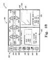
- One of the plurality of user interface screensmay be a home screen having a plurality of icons.
- Each iconmay be associated with a respective one of the plurality of user interface screens.
- the plurality of iconsmay include one or more of a patient icon, a spirometry icon, a vest-and-spirometry icon, a vest program icon, a data download icon, and a help icon. Selection of any of the plurality of icons results in an associated screen being displayed on the display.
- the HFCWO therapy systemmay comprise a garment, such as a wrap or a vest, having a double fabric layer providing at least one inflatable bladder, or between which at least one inflatable bladder is situated. A pair of hoses may be routed through associated slits in the wrap to establish fluid communication with the bladder.
- a garment for HFCWO therapymay comprise a mesh fabric layer and at least one inflatable bladder.
- a layer facing the patientmay be a low air loss layer having a plurality of perforations through which air is expelled toward the patient to enhance cooling of the patient and/or to enhance evaporation of perspiration.
- the garmentis couplable to a sheet under a patient via one or more couplers.
- the couplersmay comprise one or more garters each having a strap coupled to the garment and having a clip that releasably couples to the sheet.
- An inner layer of material of the garmentmay be a wicking material that wicks moisture away from the patient.
- the garmentmay have at least one cooling fluid channel configured to receive a cooling fluid therein to cool the patient during HFCWO therapy.
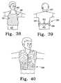
- a garment to be worn by a patient during high frequency chest wall oscillation (HFCWO) therapymay be made at least, in part, from clinical camouflage material and may have at least one inflatable bladder.
- the clinical camouflage materialmay be impregnated with activated charcoal.
- the clinical camouflage materialmay be impregnated with an antimicrobial.
- a garment to be worn by a patient during high frequency chest wall oscillation (HFCWO) therapymay comprise a front panel configured to cover a front of a patient's chest and having at least one inflatable bladder.
- a right strapmay be coupled at two locations to the front panel. The right strap may cooperate with the front panel to form a first loop around a patient's right arm.
- a left strapmay be coupled at two locations to the front panel. The left strap may cooperate with the front panel to form a second loop around a patient's left arm.
- the garmentmay have a neck strap and a torso strap.
- the neck strapmay be coupled at two locations to the front panel and may cooperate with the front panel to form a first loop around a patient's neck.
- the torso strapmay be coupled at two locations to the front panel and may cooperate with the front panel to form a second loop around a patient's torso.
- An apparatus to be worn by a patient during high frequency chest wall oscillation (HFCWO) therapymay comprise a garment having a plurality of air chambers and a plurality of flow regulators carried by the garment.
- the garmentmay cover at least a portion of a patient's chest.
- the flow regulatorsmay be openable to permit pressurized air to reach an associated one of the plurality of air chambers and the flow regulators may be closeable to block pressurized air from reaching the associated one of the plurality of air chambers.
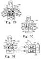
- the flow regulatorsmay each have a knob which is accessible on the exterior of the garment to open and close the associated one of the plurality of air chambers.
- One or more of the plurality of air chambersmay have a cut-out to accommodate a portion of an associated one of the knobs.
- the plurality of air chambersmay comprise side-by-side pairs of first and second air chambers and each of the first air chambers may be situated vertically above an associated one of the second air chambers.
- the flow regulatorsmay include a pair of side-by-side valves and each of the side-by-side valves may be located in a space between the associated first and second air chambers.
- the first and second air chambersWhen each of the side-by-side valves are opened, the first and second air chambers may be in fluid communication and when each of the side-by-side valves are closed, the fluid communication between the first and second air chambers may be blocked.
- the plurality of air chambersmay further comprise a side-by-side pair of third air chambers and each of the third air chambers may be situated vertically below an associated one of the second air chambers.
- the flow regulatorsmay comprise an additional pair of side-by-side valves which may be located in a space between the associated second and third air chambers.
- Each of the first air chambershave a first volume that may be larger than a second volume of each of the second air chambers and the second volume may be larger than a third volume of each of the third air chambers.
- the garmentmay be openable and closeable along a split line that extends generally vertically between the side-by-side pairs of first, second, and third air chambers.
- the garmentmay further comprise a hose interconnecting a first air chamber of the plurality of air chambers and a second air chamber of the plurality of air chambers.
- the plurality of flow regulatorsmay comprise a hose clamp coupled to the hose.
- the hose clampmay be accessible to be manipulated to open and close the hose.
- the first air chamber to which the hose is coupledmay be located above the second air chamber to which the hose is coupled.
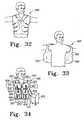
- a system for applying high frequency chest wall oscillation (HFCWO) therapy to a patientmay comprise a garment that has a plurality of air chambers and that is configured to cover at least a portion of the patient's chest.
- the systemmay further have an air pulse generator operable to produce a first oscillating pressure and a second oscillating pressure.
- the first oscillating pressuremay be communicated to at least a first air chamber of the plurality of air chambers and the second oscillating pressure may be communicated to at least a second air chamber of the plurality of air chambers.
- the air pulse generatormay have a first oscillating diaphragm assembly operable at a first frequency associated with the first oscillating pressure and may have a second oscillating diaphragm assembly operable at a second frequency associated with the second oscillating pressure.
- the systemmay also have a first blower coupled to the first oscillating diaphragm assembly and operable to establish a first baseline pressure associated with the first oscillating pressure and may further have a second blower coupled to the second oscillating diaphragm assembly and operable to establish a second baseline pressure associated with the second oscillating pressure.
- a high frequency chest wall oscillation (HFCWO) therapy systemmay comprise an air pulse generator operable to produce an oscillating pressure and a coolant system operable to deliver a cooling fluid.
- the systemmy further comprise a garment configured to be worn by a patient and cover at least a portion of the patient's chest.
- the garmentmay have at least one inflatable air chamber in communication with the oscillating pressure and at least one channel to receive the cooling fluid.
- FIG. 1is a perspective view of a first embodiment of a HFCWO therapy system showing the HFCWO therapy system supported on a siderail of a hospital bed, a hose supplying pressurized air to the HFCWO therapy system, and a pair of hoses coupled to the HFCWO therapy system and coupled to a vest positioned on a patient supported on the bed;
- FIG. 2is a perspective view showing two HFCWO therapy systems, one supported on a siderail of a hospital bed and one supported on an accessory rail of a headwall of a patient room;
- FIG. 3is an enlarged perspective view showing the controls of the HFCWO therapy system of FIG. 1 ;
- FIG. 4is a block diagram of the HFCWO therapy system of FIGS. 1-3 ;
- FIG. 5is a perspective view showing a second embodiment of a HFCWO therapy system in which a housing is supported on a wheeled pedestal, the housing carries a 2-line display screen, a pair of handles, and two air ports through which high frequency air pulses are routed from the HFCWO therapy system to a garment worn by a patient, and in which the pedestal supports a pair of storage bins having hinged lids;
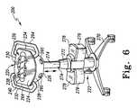
- FIG. 6is a perspective view, similar to FIG. 5 , showing the housing raised to a higher elevation by adjustment of the wheeled pedestal;
- FIG. 7is a perspective view, similar to FIG. 5 , showing the lids moved to an opened position to provide access to the storage bins;
- FIG. 8is a perspective view, similar to FIG. 5 , showing a remote on/off switch coupled to the HFCWO therapy system;
- FIG. 9is a screen shot of the display screen showing a manual program mode of the HFCWO therapy system
- FIG. 10is a screen shot of the display screen showing the status of the HFCWO therapy system
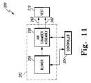
- FIG. 11is a block diagram of the HFCWO therapy system of FIGS. 5-10 ;
- FIG. 12is a perspective view of a third embodiment of a HFCWO therapy system showing a housing supported on a rolling stand, the housing having a vertically-adjustable large display, a pair of handles, a lower storage compartment, two large air ports through which air pulses are routed from the HFCWO therapy system to a garment, and a small port through which pressurized air is supplied to a respiratory therapy device, such as a nebulizer;
- a respiratory therapy devicesuch as a nebulizer
- FIG. 13is a perspective view, similar to FIG. 12 , showing the display raised to a higher position in which an upper storage compartment is accessible;
- FIG. 14is a perspective view, similar to FIG. 13 , showing a hose coupled to a pressurized air port in the housing and a mask at the end of the hose;
- FIG. 15is a perspective view, similar to FIG. 14 , showing an electronic stethoscope coupled to an input port of the system of FIG. 12 ;
- FIG. 16is a screen shot of a therapy programs screen that appears on a display screen of the display and that has a number of program options indicative of different modes of operation of the system;
- FIG. 17is a screen shot of a screen that appears on the display screen when the system is in a manual program mode
- FIG. 18is a screen shot of a home screen of the system of FIGS. 12-15 ;
- FIG. 19is a block diagram showing an electronic spirometer coupled to the system of FIG. 12 ;
- FIG. 20is a screen shot of a screen showing the output of the spirometer of FIG. 19 ;
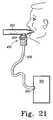
- FIG. 21shows a patient holding a mouthpiece in his mouth, the mouthpiece being coupled to a nebulizer
- FIG. 22is a block diagram showing a compressor and a pressurized air reservoir located in the housing of the system of FIG. 12 , the pressurized air reservoir supplying pressurized air to the nebulizer of FIG. 21 ;
- FIG. 23is a block diagram showing a vacuum pump and a vacuum reservoir located in the housing of the system of FIG. 12 , the vacuum reservoir supplying vacuum to a suction device;
- FIG. 24is a perspective view showing a wrap vest having slits in which tubes may be inserted;
- FIG. 25is a perspective view showing a mesh wrap
- FIG. 26is a perspective view showing a low air loss wrap
- FIG. 27is a perspective view showing a wrap with integrated flat tubing
- FIG. 28is a perspective view showing a sheet clamped wrap couplable to a sheet underlying a patient
- FIG. 29is a perspective view showing a vest having a plurality of air chambers and a set of valves having knobs that are manipulated to open and close associated ones of the air chambers;
- FIG. 30is a perspective view showing a vest having a plurality of air chambers, a set of hose extending between respective air chambers, and a set of hose clamps coupled to respective hoses;
- FIG. 31is partly a perspective view and is partly a diagrammatic view of a system including a vest having a plurality of air chambers and an air pulse generator that is operable to deliver a first oscillating pressure to first and second air chambers of the vest and to deliver a second oscillating pressure to third and fourth air chambers of the vest;
- FIG. 32is a perspective view showing a vest having an inner layer of material made from a wicking material
- FIG. 33is a perspective view showing a low air loss vest
- FIG. 34is a perspective view showing a vest having a plurality of air chambers and cooling channels
- FIG. 35is a perspective view showing a sheet clamped vest similar to the wrap shown in FIG. 28 ;
- FIG. 36is a front perspective view of a garment having a front panel
- FIG. 37is rear perspective view of the garment of FIG. 36 showing left and right straps that cooperate with the front panel to form loops that receive the patients left and right arms, respectively;
- FIG. 38is a front perspective views showing an apron-like garment
- FIG. 39is a rear perspective view of the garment of FIG. 37 showing a neck strap and a torso strap;
- FIG. 40is a perspective view showing a vest made from clinical camouflage material
- FIG. 41is a screen shot of a patient screen of the system of FIGS. 12-15 showing a list of patients for which operating parameters are stored and showing patient information pertaining to a selected one of the patients;
- FIG. 42is a screen shot of a patient edit screen of the system of FIGS. 12-15 showing various touchscreen keys which are used to edit the patient information stored in the system;
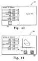
- FIG. 43is a screen shot of a spirometry screen of the system of FIGS. 12-15 prior to a spirometry test being run by the system;
- FIG. 44is a screen shot of the spirometry screen of the system of FIGS. 12-15 after a spirometry test has been run by the system showing tabular and graphical data related to the spirometry test;
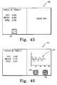
- FIG. 45is a screen shot of a vest-and-spirometry screen of the system of FIGS. 12-15 prior to a vest-and-spirometry test being run by the system;
- FIG. 46is a screen shot of the vest-and-spirometry screen of the system of FIGS. 12-15 after a vest-and-spirometry test has been run by the system showing tabular and graphical data related to the vest-and-spirometry test;
- FIG. 47is a screen shot of a vest program screen of the system of FIGS. 12-15 having vest mode control buttons which are usable to establish which mode is to have the associated parameters programmed;
- FIG. 48is a screen shot of a vest program edit screen of the system of FIGS. 12-15 showing edit keys on the left side of the screen that are usable to edit the parameters listed on the right side of the screen;
- FIG. 49is a screen shot of a data transmission screen of the system of FIGS. 12-15 showing buttons on the left side of the screen that are usable to initiate a data transmission from the system to a printer, a computer, or a portable wireless device;
- FIG. 50is a screen shot of a data transmission confirm screen of the system of FIGS. 12-15 showing buttons that are usable to confirm or to cancel the data transmission;
- FIG. 51is a screen shot of a help screen of the system of FIGS. 12-15 showing a list of the various portions of the system for which information is stored in the system to assist user to learn about the operation of the system;
- FIG. 52is a perspective view of another embodiment of a HFCWO therapy system showing an air pulse generator supported on a shelf of a wheeled pedestal, the wheeled pedestal having a vertically oriented telescopic column, a chart holder coupled to a front of an upper segment of the telescopic column, hose clips coupled to the sides of the upper segment of the telescopic column, casters coupled to a set of legs extending from a bottom segment of the telescopic column, a push handle extending rearwardly from the shelf, and a release handle situated just below a side region of the shelf for unlocking an elevation adjustment mechanism situated in an interior region of the telescopic column to permit the upper segment of the column to be raised and lowered relative to the lower segment; and
- FIG. 53is a top plan view of the HFCWO therapy system of FIG. 52 showing the shelf having a larger footprint than the air pulse generator such that the shelf has portions extending beyond the front, back, and sides of the air pulse generator, and showing one of the sides regions of the shelf having a notch which opens into a circular aperture which is sized and configured to receive a mouthpiece or other piece of auxiliary equipment which is used with the air pulse generator during HFCWO therapy.
- airas used in the specification and claims is used broadly to include regular or ambient air, medical air, nitrogen, oxygen, and any other breathable, as well as non-breathable, gas available in a hospital or healthcare facility.
- hospitaland “healthcare facility” are used interchangeably, and each is intended to broadly include hospitals, healthcare facilities, nursing homes, outpatient clinics, doctors' offices, medical care facilities, and the like.
- respiratory therapyand “airway clearance therapy” are used interchangeably, and each is intended to broadly include a HFCWO therapy, a positive expiratory pressure (PEP) therapy, a nebulizer therapy, an intermittent positive pressure breathing (IPPB) therapy, a cough assist therapy, a suction therapy, a bronchial dilator therapy, and the like.
- PEPpositive expiratory pressure
- IPPBintermittent positive pressure breathing
- cough assist therapya suction therapy
- suction therapya bronchial dilator therapy
- bronchial dilator therapyand the like.
- vacuumas used in the specification and claims is used broadly to include negative pressures or pressures below atmospheric pressure.
- FIGS. 1-4illustrate a first embodiment 100 of a HFCWO therapy system according to this disclosure.
- the HFCWO therapy system 100is supported on a siderail 102 of a hospital bed 104 .
- the system 100generates HFCWO air pulses for application to an inflatable vest 106 positioned on a patient 108 .
- the system 100includes a housing 110 having a pair of air ports 112 .
- the vest 106includes an inflatable bladder 114 having a pair of air ports 116 .
- a pair of hoses 118are releasably coupled to the ports 112 of the housing 110 and the ports 116 of the bladder 114 .
- the air pulsesare routed from the system 100 to the vest 106 via the hoses 118 .
- any of the garments disclosed herein and shown in FIGS. 24-40may be used with system 100 , if desired.
- the system 100includes an air pulse generator 120 which is located in an interior region of the housing 110 .
- the air pulse generator 120is operable to produce the HFCWO air pulses.
- the air pulse generator 120includes a self-oscillating valve 122 coupled via a hose 126 to a source of pressurized air, such as a hospital pressurized air system which includes one or more outlets 124 that are located in hospital rooms to provide connection points to the pressurized air system.
- the hose 126is also coupled to a port 128 of the housing 110 .
- port 128is provided on the bottom of housing 110 , but may be provided on some other part of housing 110 , such as the back, front, top, or one of the sides of the housing 110 , if desired.
- the air pulse generator 120includes an air amplifier 130 coupled to the self-oscillating valve 122 and coupled to the bladder 114 of the vest 106 via a pair of hoses 118 .
- system 100may have only a single hose 118 or may have more than two hoses 118 , if desired.
- Various hose segments or other conduits that extend from housing 110 to vest 106are considered to be a “hose” according to this disclosure.
- the self-oscillating valve 122is driven by pressurized air from the pressurized air outlet 124 to produce oscillating pressure comprising first pressure pulses having a first pressure and a first volume flow rate for application to the air amplifier 130 .
- the air amplifier 130converts the first pressure pulses into oscillating pressure comprising second pressure pulses that are communicated to the bladder 114 .
- the second pressure pulseshave a second pressure that is smaller than the first pressure and have a second volume flow rate that is greater than the first volume flow rate.
- the self-oscillating valve 122includes a pair of proportioning valves 132 , shown diagrammatically in FIG. 4 , which are coupled to a pressure control 134 and a frequency control 136 which are mounted on the housing 110 as shown in FIGS. 1-3 .
- the pressure control 134is operable to vary a base line pressure or steady state pressure about which the air pulses oscillate and the frequency control 136 is operable to vary the frequency of the air pulses.
- controls 134 , 136comprise knobs that are rotated or turned to adjust the amount by which the respective valves 132 are opened or closed.
- hose 124splits into two segments that couple to respective valves 132 .
- hose 126couples to an inlet of a manifold that provides flow paths from the inlet to two outlets which are, in turn, coupled to the valves 132 of valve 122 .
- hose 126may couple to valve 122 and valve 122 may include flow passages that direct air from hose 126 to valves 132 .
- Valve 122further includes a valve member 131 , shown diagrammatically in FIG. 4 , which moves back and forth within a valve chamber at a frequency dictated by the position of control 136 .
- the base line pressure or steady state pressure of the oscillating pressure which is communicated through the valve chamber to air amplifier 130is dictated by the position of control 134 as mentioned above.
- Valve 122includes a valve body 133 which defines the valve chamber in which valve member 131 reciprocates.
- the valve body 133may comprise one or more pieces of material and typically will also have a set of flow channels through which pressurized air flows so as to cause the reciprocation of valve member 131 . Some of the set of flow channels communicate with the valve chamber through respective ports.
- Valve 122may also have cross-over valves and/or check valves or the like to control the flow of pressurized air through the various flow channels at different times during the reciprocation of valve member 131 within the valve chamber of valve body 133 .
- the self-oscillating valve 122is of the type supplied by J.W.F. Technologies as Numatics Model No. L23PP4520, and the air amplifier 130 is of the type marketed by Pelmar Engineering Ltd. as ITW Vortec Model No. 902. While the pressure of the pressurized air supplied to the self-oscillating valve 122 is dictated by the components and configuration of the medical gas system of the associated healthcare facility, pressures of such systems typically range from about 40 to about 100 p.s.i. (pounds per square inch) and the air that is supplied by such systems is usually at a relatively low flow rate, which flow rate is established, at least in part, by the internal components of the associated outlet 124 .
- the pressure within bladder 114 of vest 106 during HFCWO therapyis typically on the order of about 0.1 p.s.i. (or even less) to about 1.2 p.s.i. (or even more) and the volume flow rate of air during HFCWO may be on the order of about 20 in 3 (or less) per cycle to about 30 in 3 (or more) per cycle. In one embodiment, the volume flow rate of air is about 29 in 3 per cycle.
- valve 122 and air amplifier 130are chosen so as to reduce the incoming pressure from outlet 124 down to a suitable pressure range for HFCWO therapy and to increase the flow rate up to be a suitable volume flow rate range for HFCWO therapy.
- embodiments of system 100 having series and/or parallel combinations of two or more air amplifiers 130are within the scope of this disclosure, as are embodiments having one or more pressure regulators situated in the flow path between hose 124 and valve 122 and/or situated in the flow path between valve 122 and air amplifier 130 (or amplifiers 130 if more than one are provided).
- the frequency of the air pulses applied to the bladder 114 of vest 106is adjustable to be from about 0 Hertz (Hz) to about 20 Hz as indicated by the indicia adjacent to control 136 shown in FIG. 3 .
- the operational frequency of system 100is 5 Hz or higher, which is a much higher frequency than the frequency typically used for cardio pulmonary resuscitation (CPR).
- the indicia adjacent to control 134include numerals 1 through 10, which numbers are relative settings corresponding generally to the amount by which the valve 132 associated with control 134 is opened, with a setting of 10 corresponding to fully opened.
- the system 100includes a timer control 138 mounted on the housing 110 to provide an alarm signal to indicate that a therapy time selected by a patient or caregiver has ended.
- timer control 138comprises a knob that is turned by a desired amount to set a mechanical timer that is carried by housing 110 and that is coupled to control 138 .
- the system 100uses a rotary spring wound timer.
- the timer controlled by control 138may be a so-called “egg timer.”
- the mechanical timerproduces an audible alarm, such as ringing a bell or chime included in the timer, when the therapy time has elapsed.
- a hanger 140is coupled to housing 110 and is configured to suspend the housing 110 from any suitable support device, such as the siderail 102 of the hospital bed 104 .
- the housing 110may be supported by an accessory mounting rail 142 of a headwall 144 in a patient room 146 of a hospital as shown with respect to the system 100 shown on the right side in FIG. 2 .
- hanger 140is a solid piece of material that extends rearwardly from the top of housing 110 and forms a hook that is configured to catch on the siderail or headwall rail or other similar support structure.
- hanger 140may extend from the back of housing 110 at some other location, such as, for example, midway between the top and bottom of housing 110 .
- hanger 140may be formed integrally with other portions of housing 110 , such as the top or back of housing 110 , rather than being a separate component that couples to housing 110 . It is within the scope of this disclosure for system 100 to have some other types of hangers for supporting housing 110 relative to a support device. For example, other hangers may comprise clamps or straps. Furthermore, it is within the scope of this disclosure for some or all of hanger 140 to move between a storage position, such as a position retracted into or adjacent housing 110 or even a position folded against housing 110 , and a use position in which hanger 140 is deployed for use.
- the housing 110 and the hanger 140are both made of high-strength, light weight plastic in the illustrated embodiment but may be made from any materials having suitable strength.
- system 100produces a pressure having a steady state air pressure component (or “bias line pressure”) and an oscillating air pressure component.
- the airpulses oscillate the bladder 114 , while keeping it inflated.
- the bladder 114applies an oscillating compressive force to the chest of the patient 108 .
- the oscillating compressive force applied to the chesthas an oscillatory force component and a steady state force component which respectively correspond to the oscillating air pressure component and the steady state air pressure component.
- the steady state air pressure componentis greater than the atmospheric pressure with the oscillatory air pressure component riding on the steady state air pressure component.
- steady state componentas used herein, including in the claims, is not intended to be limited only to an unchanging pressure having substantially no fluctuations, although such an unchanging pressure would be an example of a steady state component of the pressure. Due to many factors, including the fact that a high frequency oscillatory pressure is superimposed on the so-called “steady state component,” the “steady state component,” itself, may fluctuate by some amount but yet still be considered a “stead state component” within the scope of this disclosure.
- the resulting composite waveformprovides oscillation cycles of the bladder 114 that are effective at moving the chest of the patient 108 , because at no point in the cycles is the pressure applied to the chest by bladder 114 below atmospheric pressure.
- vest 106has an established leakage rate to permit pressurized air to exhaust from vest 106 to the ambient atmosphere. Depending upon the design of vest 106 , such leakage may occur through holes created by stitching between layers of material that define bladder 114 , through holes created by stitching between a single layer and an enclosure that defines bladder 114 , through discrete holes formed in one or more layers of vest 106 , or through a loose weave of material forming a part of vest 106 .
- system 100is an all-pneumatic system without any electrical components, although the timer is a mechanical timer.
- the system 100is couplable to outlet 124 and is operably driven by pressurized air from a pressurized gas system which communicates pressurized air to system 100 through the associated outlet 124 of a hospital or a healthcare facility. Therefore, system 100 does not include a blower or a motor-and-diaphragm assembly, nor does system 100 include the attendant electronic circuitry associated with such components, thereby reducing the cost of, the weight of, and the space occupied by, system 100 as compared to prior art HFCWO systems.
- the system 100is so compact that the housing 110 of the system 100 can be supported on a siderail or an accessory mounting rail of a hospital bed as shown, for example, in FIGS. 1 and 2 .
- the width and the depth of the housing 110may be on the order of about 3 inches to about 9 inches, and the height of the housing 110 be on the order of about 6 inches to about 12 inches.
- housing 110may have dimensions that are larger than, or smaller than, the above-listed dimensions.
- FIGS. 5-11illustrate a second embodiment 200 of a HFCWO therapy system according to this disclosure.
- system 200includes an air pulse generator 202 and a controller 204 .
- the air pulse generator 202comprises a blower 206 and an air chamber assembly 208 .
- the blower 206supplies pressurized air to assembly 208 and cooperates with assembly 208 to produce HFCWO air pulses that are communicated to a vest 210 of system 200 .
- the air chamber assembly 208includes an air chamber shell (not shown) which receives pressurized air from the blower 206 and a pair of opposed diaphragm assemblies (not shown) which are reciprocated toward and away from one another by a motor and linkage assembly to produce air pulses for application to the vest 210 .
- This type of air pulse generatoris included in a HFCWO system marketed by Advanced Respiratory, Inc. of St. Paul, Minn. as the Model 104 system and is disclosed in U.S. patent application Ser. No. 10/295,782 which published as US Patent Application Publication No. US 2004/0097842 and which is hereby incorporated by reference herein.
- system 100is driven by pressurized air from the hospital pressurized air outlet 124
- system 200has an on-board blower 206 for supplying pressurized air.
- System 200includes a housing 220 supported on a wheeled pedestal 222 as shown in FIGS. 5-8 .
- the housing 220includes a top wall 224 , a bottom wall 226 , a front wall 228 , a rear wall 230 , and a pair of side walls 232 , 234 .
- the air pulse generator 202 and the controller 204are located in an interior region of the housing 220 .
- the front wall 228has a pair of air ports 260 .
- the air ports 260are coupled to vest 210 by a pair of hoses 262 as shown diagrammatically in FIG. 11 .
- a user interface 236is coupled to the top wall 224 and is coupled to the controller 204 .
- the user interface 236is configured to allow a caregiver to control the operation of the air pulse generator 202 .
- the user interface 236includes a display screen 238 and a keypad 240 .
- the keypad 240has the following buttons: on button 242 , off button 244 , upper left button 246 , lower left button 248 , upper middle button 250 , lower middle button 252 , upper right button 254 , and lower right button 256 .
- the keypad 240surrounds the display screen 238 .
- Display screen 238is a liquid crystal display (LCD) screen in some embodiments, although interface 236 may have any suitable type of electronic display screen according to this disclosure.
- display screen 238is a touch screen which includes appropriate areas thereon corresponding to one or more of buttons 242 , 244 , 246 , 248 , 250 , 252 , 254 , 256 .
- the on button 242is located on the left side of display screen 238 and the off button 244 is located on the right side of display screen 238 .
- the buttons 246 , 250 and 254are located above and adjacent to the top of display screen 238 and the buttons 248 , 252 and 256 are located below and adjacent to the bottom of display screen 238 .
- the caregivermay modify the operation of air pulse generator 202 by using the buttons 246 , 248 , 250 , 252 , 254 , 256 .
- the function of the buttons 246 , 248 , 250 , 252 , 254 , 256varies depending on the current state or mode of the air pulse generator 202 .
- air pulse generator 202is operable in any of the modes described in U.S. patent application Ser. No. 10/295,782 which published as US Patent Application Publication No. US 2004/0097842 and which is already incorporated by reference herein.
- modesinclude, for example, a manual mode, a step program mode, a sweep program mode, a training mode, and a custom program mode.
- Exemplary information which appears on display screen 238 in the manual modeis shown in FIG. 9 .
- display screen 238shows two lines of information.
- the upper line of informationincludes the words “Frequency,” “Pressure,” and “Time Set.”
- the lower line of informationshows the current settings for the corresponding parameter.
- the frequency of system 200is set for 12 Hz
- the pressure settingis 4, and the therapy duration is set for 15 minutes.
- the pressure number shown on display screen 238 in the manual modeis a relative number (e.g., an integer between 0 and 10) and not the actual steady state pressure.
- the pressure number shown on display screen 238may be the steady state pressure setting (e.g., 0.1 p.s.i. to 1.2 p.s.i.).
- the two-line display of information on display screen 238enables system 200 to provide more information to a user or caregiver than the one-line display screen included in the prior art Model 104 system mentioned above.
- buttons 246 , 248may be pressed by a user or caregiver to increase and decrease, respectively, the frequency setting of system 200 ; buttons 250 , 252 may be pressed by a user or caregiver to increase and decrease, respectively, the pressure setting of system 200 ; and buttons 254 , 256 may be pressed by a user or caregiver to increase and decrease, respectively, the time setting of system 200 .
- the user or caregiverinitiates the HFCWO therapy according to the parameters by pressing the on button 242 . If the user or caregiver wants to stop the therapy, the user or caregiver does so by pressing the off button 244 . If the user or caregiver pressure off button 244 when no HFCWO therapy is occurring, then system 200 powers down.
- a remote on/off pendant 266is coupled to the controller 204 by an extension cord 268 , as shown in FIG. 8 , and includes on and off buttons which may be used in the same manner as just described regarding the manner in which on and off buttons 242 , 244 are used.
- the on and off buttons of pendant 266are color coded such that the on button is green and the off button is red.
- the HFCWO therapyautomatically stops when the time duration is complete, and a message such as “Session Ended, Therapy Complete” is displayed on the display panel 238 as shown in FIG. 10 .
- the display panel 238also provides feedback to the caregiver as to the status of system 200 when requested via appropriate presses of buttons 242 , 244 , 246 , 248 , 250 , 252 , 254 , 256 .
- buttons 242 , 244 , 246 , 248 , 250 , 252 , 254 , 256simultaneously may result in corresponding status information being displayed on screen 238 and the type of information displayed may vary depending which combination of two buttons 242 , 244 , 246 , 248 , 250 , 252 , 254 , 256 are simultaneously pressed.
- the messagesare displayed as text on the display panel 238 .
- the caregivermay use the buttons 246 , 248 , 250 , 252 , 254 , 256 to program the air pulse generator 202 .
- the caregiverin addition to the manual program mode, the caregiver can choose one of three pre-set program modes.
- the three pre-set program modesare stored as software in one or more memory devices included in controller 204 .
- controller 204In addition to display screen 238 , buttons 242 , 244 , 246 , 248 , 250 , 252 , 254 , 256 , and one or more memory devices, controller 204 also includes all other electrical components associated with the operation of system 200 . In one embodiment, controller 204 is substantially the same as that shown and described in U.S. patent application Ser. No. 10/295,782 which published as US Patent Application Publication No. US 2004/0097842 and which is already incorporated by reference herein. Two lines of up to 24 characters each are displayable on display screen 238 .
- system 200includes a housing 220 supported on a wheeled pedestal 222 .
- a pair of generally C-shaped handles 264are coupled to the housing 220 and are gripped by users or caregiver to maneuver system 200 along a floor.
- Each handle 264has one end coupled to front wall 228 and another end coupled to rear wall 230 .
- the handles 264are coupled to walls 228 , 230 of housing 220 closer to top wall 224 than to bottom wall 226 .
- each of the handlesextend around the sides of housing 220 with a central portion of each handle 264 being spaced from the respective side wall 232 , 234 of housing 220 .
- the bottom wall 226 of the housing 220is coupled to the pedestal 222 by a lockable swivel joint (not shown) which is unlockable to permit titling of housing 220 relative to pedestal 222 about a generally horizontal axis. This allows the caregiver to tilt the housing 220 to change the viewing angle of the display screen 238 .
- the pedestal 222is vertically extendable and retractable to support the housing 220 at selected elevations.
- the pedestal 222includes a wheeled base 270 , a stationary portion 272 coupled to wheeled base 270 , and a telescoping portion 274 coupled to the stationary portion 272 and coupled to the bottom wall 226 of the housing 220 by the lockable swivel joint.
- portions 272 , 274comprise cylindrical tubes with round cross sections, but tubes having other cross sections such as polygonal (e.g., square, rectangular, triangular, hexagonal, etc.) or oval or elliptical or any other desired shape are within the scope of this disclosure.
- the telescoping portion 274is movable generally vertically relative to the stationary portion 272 between a lowered position shown in FIG. 5 and a raised position shown in FIGS. 6-8 .
- the telescoping portion 274is pivotable about a generally vertical axis relative to the stationary portion 272 .
- the lockable swivel jointmay be constructed to permit housing 220 to pivot about a generally vertical axis relative to pedestal 222 .
- An elevation adjustment mechanism and/or locking mechanism(not shown), such as a locking gas spring, normally locks the telescoping portion 274 in place relative to the stationary portion 272 but is unlockable to permit telescoping movement of portion 274 relative to portion 272 .
- one or more release handles or leversare coupled to one or both handles 264 and are movable to release the locking mechanism.
- a Bowden wire or cablee.g., a sheath having a wire extending therethrough
- Such a Bowden wiremay be routed from the release lever, through a portion of the corresponding handle 264 , through housing 220 , and through a portion of pedestal 222 . Movement of the release lever, in such embodiments, causes the wire to move within the sheath and unlock the gas spring.
- the gas springwhen released, may be of the type that is biased to extend thereby providing an upward force that assists the user or caregiver in moving housing 220 upwardly.
- a release lever or handleis coupled to pedestal 222 beneath housing 220 and is movable to unlock and lock the elevation adjustment mechanism and/or locking mechanism.
- the elevation adjustment mechanism and/or locking mechanismmay comprise a hydraulic cylinder or a pneumatic cylinder and a foot pedal (not shown) may be coupled to base 270 and movable to raise and lower the height of the pedestal 222 .
- a repetitive pumping action of such a foot pedal through a stroke lengthmay result in hydraulic fluid being pumped into the hydraulic cylinder (or air being pumped into the pneumatic cylinder) to raise the pedestal 222 and depressing and holding the foot pedal in its lowest position may result in hydraulic fluid exiting the hydraulic cylinder (or air exiting the pneumatic cylinder) to lower the pedestal 222 .
- a jack screw arrangementmay be provided in pedestal 222 such that rotation of housing 220 and portion 274 in one direction about a generally vertical axis relative to portion 272 results in extension of portion 274 relative to portion 272 , thereby to lift housing 220 relative to base 270 , and rotation of housing 220 and portion 274 in an opposite direction relative to portion 272 about the generally vertical axis results in retraction of portion 274 relative to portion 274 , thereby to lower housing 220 relative to base 270 .
- a latch or retractable pin or the likemay be provided to serve as a locking mechanism to prevent rotation of portion 274 relative to portion 272 .
- Such a pin or latchmay be coupled to portion 272 and may have a portion that enters a hole or recess provided in portion 274 to lock portion 272 from rotating relative to portion 274 and that is withdrawn from the hole or recess to permit rotation of portion 272 relative to portion 274 .
- an electrically powered linear actuatormay be provided as an elevation adjustment mechanism to raise and lower portion 274 relative to portion 272 thereby to raise and lower, respectively, housing 220 relative to base 270 .
- Such a linear actuatormay be powered by a battery carried within housing 220 or on base 270 .
- such a linear actuatormay be powered by electrical power received from a wall outlet when a power cord (not shown) of system 200 is plugged into the outlet. If system 200 has an on-board battery to power the linear actuator, the battery may be recharged when system 200 is plugged into a power outlet.
- controller 204includes battery recharging circuitry.
- a hand cranking mechanismmay be provided as an elevation adjustment mechanism to extend and retract portion 274 relative to portion 272 thereby to raise and lower, respectively, housing 220 relative to base 270 .
- a hand cranking mechanismmay include a hand crank coupled to portion 272 , a worm gear arrangement coupled to the hand crank, and a rack-and-pinion arrangement coupled to the worm gear arrangement and coupled to portion 274 .
- One of the gears of the worm gear arrangementmay be the pinion of the rack-and-pinion arrangement, with the rack being coupled to portion 274 to raise and lower therewith as the hand crank turns a worm of the worm gear arrangement which meshes with the pinion.
- a pair of storage bins 276are coupled to the stationary portion 272 of pedestal 22 on opposite sides thereof.
- a lid 278is coupled to each bin 276 by a suitable hinge mechanism, such as a living hinge, one or more flexible straps, one or more pivot pins, or the like.
- Each lid 278is movable relative to the associated bin 276 between a closed position blocking access to a storage compartment of the respective bin 276 and an opened position allowing access to the storage compartment through an open top of the associated bin 276 .
- the lids 278are opaque and bins 276 are semi-transparent or substantially transparent. In some embodiments, the lids 278 are semi-transparent or substantially transparent.
- bins 276provide spaces for receipt of other parts of system 200 such as garments (such as vests or wraps), hoses, mouthpieces, masks, sputum bowls, electrical cords, and equipment for other respiratory therapies, such as a positive expiratory pressure (PEP) therapy, a nebulizer therapy, an intermittent positive pressure breathing (IPPB) therapy, a cough assist therapy and/or other types of a suction therapy such as negative wound pressure therapy, a bronchial dilator therapy, and the like. While the illustrative system 200 has two bins 276 coupled to pedestal 222 , systems having more or less than two bins 276 , including systems having no bins at all, are within the scope of this disclosure.
- PEPpositive expiratory pressure
- IPPBintermittent positive pressure breathing
- a locating-and-tracking badgemay be coupled to the exterior of housing 220 or pedestal 222 .
- a locating-and-tracking badgeincludes a transmitter to transmit a wireless signal, either periodically or in response to receipt by a receiver of the badge of a wireless query signal.
- the wireless signal transmitted by the badgeis received by one or more receivers located throughout the healthcare facility.
- the transmitter and receiver of the locating-and-tracking badgemay be combined as a transceiver in some embodiments and may be separate in other embodiments.
- the wireless signalsincludes a unique ID which is associated with system 200 .
- the circuitry of system 200includes a transmitter and/or receiver and/or transceiver to transmit ID data to other portions of the locating-and-tracking system, either periodically or in response to a query signal. In such embodiments, therefore, a locating-and-tracking badge does not need to be coupled to the housing 220 or pedestal 222 .
- the ID data transmitted by the circuitry of system 200may be programmable via appropriate presses of buttons 242 , 244 , 246 , 248 , 250 , 252 , 254 , 256 to place system 200 into an ID programming mode in which the ID data to be transmitted can be programmed.
- system 200may transmit data indicative of whether or not system 200 is currently in use and optionally, may also transmit data indicative of the amount time left before the current HFCWO therapy session will end.
- a caregiver viewing a remote display screen of a computer of the locating-and-tracking systemcan receive information regarding the whereabouts of a particular system 200 in the healthcare facility. If the information on the display screen of the computer of the locating-and-tracking system indicates that the system 200 is in use and will remain in use for some period of time, such as 30 minutes for example, then the caregiver can avoid retrieving the system 200 for use by another patient until the use by the current patient has finished.
- FIGS. 12-23show a third embodiment 300 of a HFCWO therapy system according to this disclosure.
- System 300includes a generally box-shaped housing 302 having a lower portion 304 and an upper portion 306 as shown in FIG. 12 .
- the lower portion 304is supported on wheels 308 that are rotatably coupled to respective arms 309 that extend outwardly and slightly downwardly from the sides of lower portion 304 of housing 302 .
- the front arms 309also extend slightly forwardly from the side of housing 302 and the rear arms 309 extend slightly rearwardly from the side of housing 302 .
- the front wheels 308 and/or the rear wheels 308are able to swivel about generally vertical axes to facilitate turning of system 300 as it is transported along a floor.
- housing 302is an upright, generally rectangular structure when viewed from the front.
- Many of the heavier internal components of system 300such as motors, diaphragm assemblies, compressors, and other hardware (described in more detail below) are situated in the lower part of portion 304 so that system 300 has a relatively low center of gravity which enhances the stability of system 300 and reduces the tendency of system 300 to tip.
- the wide wheelbase created due to the fact that arms 309 support wheels 308 laterally out to the sides of housing 302 and also slightly forwardly of, and slightly rearwardly of, housing 302also enhances the stability of system 300 .
- the lower portion 304 of housing 302includes a storage compartment 310 situated behind a door 312 which is coupled to housing 302 by a suitable hinge mechanism and which is movable between a closed position blocking access to compartment 310 and an opened position allowing access to compartment 310 .
- the door 312is substantially transparent.
- the doors 312are opaque or are semi-transparent.
- a hook-like cantilevered structure 313protrudes into compartment 310 from a generally vertical wall 315 which defines the back of compartment 310 .
- Structure 313supports hoses 317 in a looped or coiled configuration as shown in FIGS. 12-15 .
- a vertical front plate of structure 313retains hoses 317 on a portion of structure 313 on which the coiled hoses 317 hang to prevent hoses 317 from falling off of structure 313 .
- other equipment or accessoriessuch as garments of system 300 may be stored in compartment 310 .
- the upper portion 306 of housing 302includes a storage compartment 314 .
- a vertical partition 319 and a horizontal shelf 321are provided within compartment 314 to subdivide compartment 314 into multiple storage spaces. Similar partitions and shelves may be provided in space 310 , if desired. In other embodiments, partition 319 and shelf 321 are omitted and compartment 321 comprises a single storage space.
- Compartments 310 , 314allow vests, hoses, mouthpieces, masks, sputum bowls, electrical cords, and other equipment associated with HFCWO therapy devices and/or additional respiratory therapy devices and/or assessment systems included in system 300 , as well as any other desired equipment or objects, to be stored in housing 302 and transported from place to place along with system 300 .
- system 300includes an air pulse generator 316 comprising a blower (not shown) and an air chamber assembly (not shown), similar to the air pulse generator 202 shown in FIG. 11 .
- the system 300includes a controller 318 similar to the controller 204 shown in FIG. 11 , except that the controller 318 has more features and capabilities as explained in more detail below.
- the air pulse generator 316 and the controller 318are located within the housing 302 . As alluded to above, air pulse generator 316 is situated in the lower part of lower portion 304 of housing 302 in the illustrative embodiment.
- Controller 318comprises one or more circuit boards and the associated circuitry which may be located anywhere within housing 302 at the option of the system designer, although it may be desirable to have the heavier circuit components, such as power transformers and the like, located in the lower part of portion 304 along with the heavier hardware components. It may also be desirable for any circuit components that are more sensitive to heating to be situated on a circuit board that is located in upper portion 306 of housing 302 away from the motors and motorized components situated in lower portion 304 . In some embodiments, system 300 has an on-board battery which is housed within, or carried by, the lower part of portion 304 .
- System 300includes components operable to provide HFCWO therapy to a patient and also includes components operable to provide additional respiratory therapies to a patient and/or components for assessing of the various therapy systems of system 300 .
- additional respiratory therapies for which the associated components may be included as part of system 300include a cough assist therapy ( FIG. 14 ), a nebulizer therapy ( FIGS. 21 and 22 ), a suction therapy, such as cough assist therapy, ( FIG. 23 ), a positive expiratory pressure (PEP) therapy, an intermittent positive pressure breathing (IPPB) therapy, and a bronchial dilator therapy.
- Examples of components of assessment systems which may be included as part of system 300include a flow meter, an electronic stethoscope 366 ( FIG.
- the assessment system of system 300may be operable to determine the efficacy of, and/or to provide data for determining the efficacy of, at least one of the respiratory therapy systems and/or the HFCWO therapy system of system 300 .
- the equipment and devices used for these additional therapies and the assessment systemsmay be stored in the storage compartments 310 , 314 , if desired.
- the upper portion 306includes a front wall 320 , a rear wall 322 , a top wall 324 , and a pair of side walls 326 , 328 .
- a user interfacesuch as a video monitor or display 330 , is coupled to the front wall 324 for vertical movement between a lowered position shown in FIG. 12 in which the monitor 330 blocks access to the upper storage compartment 314 and a raised position shown in FIGS. 13-15 in which the upper storage compartment is accessible.
- the height of the monitor 330 relative to housing 302is adjustable to suit the caregiver's convenience.
- the monitor 330includes a touch screen display panel 332 .
- Controller 318is coupled to monitor 330 and is operable to cause various screens and various data to appear on the electronic display screen of display 330 as will be described in further detail below.
- the monitor 330allows the caregiver to control the operation of the air pulse generator 316 and the operation of any of the additional respiratory therapy system(s) and/or assessment system(s) included in system 300 .
- the front wall 320has a pair of air ports 334 which are configured to be coupled to a HFCWO therapy vest via hoses 317 .
- Above air ports 334is a recess in housing 302 that accommodates display 330 therein for vertical upward and downward movement.
- the recess in housing 302 and display 330are sized such that a front surface of display 330 is generally coplanar with front wall 320 of housing 302 .
- Display 330comprises a flat screen display, such a liquid crystal display (LCD), of relatively narrow depth. The depth of display may be on the order of about 1 inch (2.54 cm) or less to about 3 inches (7.62 cm) or more.
- LCDliquid crystal display
- the recess in housing 302 to accommodate display 330therefore, has a depth that is substantially smaller than the depth of storage compartment 314 as shown in FIGS. 13-15 .
- the depth or the storage compartmentmay be on the order of two times or three times or four times or even more than the depth of the recess in which display 330 is received.
- the display 330includes an electronic display screen 332 , such as an LCD screen, a housing which carries the electronic display screen 332 , and the associated electrical components situated in the housing.
- the interface between the sides of display 330 and housing 302may include suitable guide mechanisms to guide the upward and downward movement of display 330 .
- each of the sides of display 330may be formed with a vertically oriented rail or tongue which is received in a respective vertically oriented groove formed in housing 302 .
- Such a rail and groove arrangementmay be reversed such that the sides of the display 330 are formed with grooves and the housing 302 is formed with tongues or rails that are received in the grooves of the display 330 .
- separate members having the rails or tongues and the groovesmay be coupled to housing 302 and display 330 in lieu of these guide structures being formed in the sides of display 330 and the housing 302 .
- a guide mechanismmay include one or more vertical posts or struts extending downwardly from the bottom of display 330 into a respective vertically oriented socket provided in housing 302 beneath display 330 .
- Such a vertically oriented socketmay be situated, in part, between ports 334 or outboard of ports 334 .
- the vertical partition 319 in such an embodimentmay be located so as to be situated behind the vertically oriented post when display 330 is raised so as to reduce the amount by which the vertically oriented post may block or interfere with access to the usable space of storage compartment 314 .
- display 330 and/or housing 302 and/or the guide mechanism itselfmay have suitable locking mechanisms to lock display 330 in place at selected elevations relative to housing 330 .
- a locking mechanismmay comprise, for example, one or more pins or latches carried by display which are received in apertures or recesses in housing 302 , or vice versa.
- the apertures or recessesmay be vertically spaced to define a set of vertical positions in which display 330 may be locked by receipt of the pins or latches in the associated apertures or recesses.
- Such pins or latchesmay be spring biased outwardly relative to display 330 toward housing 302 and into the apertures or recesses aligned therewith.
- a release mechanismsuch as a lever, knob, or handle may be provided on display 330 in such embodiments for retracting the pins or latches out of the apertures or recesses to unlock the display 330 for movement relative to housing 302 . If the pins or latches are coupled to housing 302 and if the display 330 has the apertures or recesses, then the release mechanism may be coupled to housing 302 .
- a spring clutch mechanismsuch as Mechlok® mechanism available from Porter Group, LLC of Novi, Mich.
- a spring clutch mechanismtypically has a rod that is movable relative to a rod housing and a spring that constricts around the rod to prevent the rod from moving relative to the rod housing.
- a release mechanismsuch as a lever, knob, or handle, may be provided either on display 330 or on housing 302 for manipulation to unlock the normally locked spring clutch mechanism by causing the spring to loosen about the rod allowing the rod to move relative to the rod housing.
- a suitable linkage mechanismsuch as Bowden wire, may be routed from the release mechanism, through the interior of display, and through a hollow interior of the vertical guide post.
- a suitable linkage mechanismsuch as Bowden wire
- one of the rod and the rod housing of a spring clutch mechanismis fastened to the vertically oriented guide post and the other of the rod and the rod housing is fastened to a portion of housing 302 , such as an internal frame member of housing 302 or a flange extending from front wall 320 in the interior region of housing 320 .
- one of the sides of display 330may have a suitable hinge mechanism defining a generally vertical axis about which display 330 pivots to open and close compartment 314 .
- the bottom of display 330may have a suitable hinge mechanism defining a generally horizontal axis about which display pivots downwardly to open compartment 314 .
- one or more suitable stopsmay be provided to prevent display from pivoting downwardly beyond a generally horizontal position in which a back of display 330 provides a work surface that caregivers may use for temporary placement of objects or for writing on charts, etc.
- the top of display 330may have a suitable hinge mechanism defining a generally horizontal axis about which display pivots upwardly to open compartment 314 .
- a lock, pin, or latchmay be provide to retain display 330 in the closed position and a release lever, knob, or handle may be provided for moving the lock, pin or latch to a position allowing the display to pivot to its opened positions.
- the top of panel 330may be coupled to a backing panel by a suitable hinge mechanism for pivoting movement about a generally horizontal axis relative to the backing panel.
- the backing panelraises and lowers along with display 330 to open and close compartment 314 .
- the backing panelis retained relative to housing 302 in such embodiments by any of the guide mechanisms described above, such as tongue (or rail) and groove arrangements or vertical guide posts.
- display 330is permitted to tilt out of the recess of housing 302 so that the electronic display screen faces upwardly by some amount, such as 30 degrees or 45 degrees or even up to 90 degrees, to provide more ergonomic viewing and access to the electronic display screen of display 330 by a caregiver or patient standing in front of system 300 .
- the hinge mechanism of this embodimentmay have friction between components of the hinge mechanism that is sufficiently high enough to maintain display 330 in a tilted orientation relative to the backing panel but not so high as to prevent a user from pivoting display 330 relative to the associated backing panel.
- a strut or other support membermay be provided between display 330 and the backing panel to maintain the display 330 in its tilted orientation relative to the backing panel.
- linkage mechanismsmay be provided in the above-described embodiments for interconnecting the pins, latches, or locks, as the case may be, with an associated release mechanism so that movement of the release mechanism results in movement of the associated pins, latches, or locks.
- Such linkage mechanismsmay comprise Bowden wires (refer to the earlier description) and/or links, sliders, cams, followers, and the like.
- electrical linessuch as wires or cables, including ribbon cables, are routed through or beside the above-described guide mechanisms or hinge mechanisms to provide an electrical connection between display 330 and the controller 318 of system 300 situated in housing 302 .
- a slotmay be provided within one of the grooves and the electrical lines may exit through an opening provided in the associated rail and be routed through the slot.
- the electrical lines between controller 318 and display 330may be omitted and display 330 may send and receive signals wirelessly to and from controller 318 .
- the front wall 320 of housing 302 of system 300has an additional pneumatic port 460 to the left of the air ports 334 as shown best in FIG. 13 .
- Port 460is couplable to a mouthpiece 452 such as the one shown, for example, in FIG. 21 , or a mask 480 as shown, for example, in FIGS. 14 and 15 .
- Mouthpiece 452 and mask 480are used with system 300 when system 300 performs one or more of the integrated additional therapies such as, for example, the nebulizer therapy, the cough assist therapy, and the PEP therapy, just to name a few.
- suction or negative pressuremay be applied to port 460 by system 300 as well, for ultimate application to the mouthpiece 452 or mask 480 coupled to port 460 .
- the front wall of the housing of display 330has a pair of input ports 362 , 364 just below the electronic display screen 332 .
- the input ports 362 , 364are configured to be connected to electronic assessment systems, such as an external flow meter (in those embodiments in which system 300 does not have an internal flow meter), an electronic stethoscope 366 , a spirometer mouthpiece 378 , a tympanic thermometer, a pulse oximeter, a respiration rate monitor, or the like.
- electronic assessment systemssuch as an external flow meter (in those embodiments in which system 300 does not have an internal flow meter), an electronic stethoscope 366 , a spirometer mouthpiece 378 , a tympanic thermometer, a pulse oximeter, a respiration rate monitor, or the like.
- one or more ports 362 , 364are provided on housing 302 instead on the housing of display 330 .
- a pair of C-shaped handles 336are coupled to the side walls 326 , 328 of the housing 302 and are grippable by a caregiver to maneuver system 300 along a floor.
- a remote on/off switch(not shown), similar to switch 266 of system 200 described above, is couplable to the controller 318 via a port on the housing 302 .
- An asset tracking badgemay be attached to one of the walls of the housing 302 so that an asset tracking system of the hospital can keep track of the location of the system 300 .
- Such an asset tracking badgemay be the same or similar to those described above in connection with system 200 .
- the circuitry of system 300includes a transmitter and/or receiver and/or transceiver to transmit ID data to other portions of the locating-and-tracking system, either periodically or in response to a query signal.
- the ID data and/or other data transmitted by such circuitry of system 300may be programmable via appropriate presses of icons or buttons on screen 332 of display 330 .
- system 300may transmit data indicative of whether or not system 300 is currently in use and optionally, may also transmit data indicative of the amount time left before the current HFCWO therapy session and/or other respiratory therapy session and/or assessment session will end.
- a caregiver viewing a remote display screen of a computer of the locating-and-tracking systemcan receive information regarding the whereabouts of a particular system 300 in the healthcare facility as well as additional information regarding the usage status of the system 300 .
- FIGS. 16 , 17 and 20show examples of user interface screens according to one embodiment of system 300 .
- FIG. 16is a screen shot of a program select screen 338 that appears on the display panel 332 when the system 300 is in a program select mode.
- the air pulse generator 316has four pre-set program modes, namely, a step program mode, a sweep program mode, a training program mode, and a custom program mode.
- the caregiverselects a particular program mode by simply touching the associated quadrant of the screen 338 .
- the caregiverselects the step program mode by touching upper left quadrant of the screen 338 .
- the step and sweep program modesare substantially as described in U.S. Patent Application Publication No. US 2004/0097842 which is already incorporated by reference herein.
- the training program modeallows the caregiver to start at a desired starting frequency and intensity for the HFCWO therapy and automatically gradually increase the frequency and intensity over a predetermined period of time or a programmed period of time to a desired maximum frequency and intensity. This is useful for frail patients and patients that are not accustomed to HFCWO therapy in order to help them get accustomed to this type of therapy before using more powerful settings.
- the software for the four pre-set program modesis stored in a memory associated with the controller 318 . In the custom program mode, the caregiver is able to create a special waveform for a particular patient's therapy.
- Such a special waveformmay be in accordance with wave type, frequency, pressure, and timing parameters of the caregiver's choosing or may be in accordance with a menu of special waveforms preprogrammed into system 300 .
- a custom waveformis shown in which system 300 operates according to a step program for a first period of time and then changes automatically to a sweep program for a second period of time.
- the air pulse generator 316is operable in a manual program mode.
- the caregivermanually sets the air pulse frequency, the bias line pressure and the duration of the HFCWO therapy.
- FIG. 17is a screen shot of a screen 340 that appears on the display panel 332 when the system 300 is in the manual program mode.
- the screen 340shows three ranges 342 , 344 , 346 of therapy settings, namely, the frequency of air pulses applied to the vest, the bias line pressure and the duration of the HFCWO therapy.
- the air pulse frequencycan be varied between 0 Hz to 20 Hz.
- the current value of the air pulse frequency setting(4, in the illustration shown in FIG.
- a box 352 to right of range 344shows the current value of the relative bias line pressure setting and a box 356 to right of range 346 shows the current value of the duration setting of the HFCWO therapy.
- the caregivermay change the air pulse frequency by touching and then dragging an arrow icon 350 toward the left side of range 342 to decrease the air pulse frequency or by touching and then dragging icon 350 toward the right side of range 342 to increase the air pulse frequency.
- the default frequencyin one embodiment is 12 Hz, although embodiments having other default frequencies are within the scope of this disclosure.
- the caregivermay vary the relative bias line pressure setting to a value between 0 and 10 by moving an arrow icon 354 toward the left side or the right side of the associated range 344 .
- the default bias line pressureis 3, although other bias line pressure default values are within the scope of this disclosure.
- the caregivermay vary the duration of the HFCWO therapy between 0 and 20 minutes by dragging an arrow icon 358 toward the left side or the right side of the associated range 346 .
- the default timeis 10 minutes.
- the therapyautomatically stops when the duration is complete, and a message is shown on the display panel 332 that that the session has ended and the therapy is complete.
- the number in box 356changes during the HFCWO to show the amount of time left before the therapy session ends and the arrow icon 358 moves to the left along range 346 to show the amount of time left in the therapy session.
- the number in box 356shows both minutes and seconds, rather than showing just minutes.
- Screen 340has a help button 360 that allows the caregiver to browse the product documentation, watch an in-service video, view clinical studies and claims, view technical literature, view user manuals, and access technical support contact information. All of this information is stored in one or more memory devices included in or associated with controller 318 of system 300 .
- memory devicesmay include one or more RAM, ROM, cache memory, or non-volatile memory devices, and the like as well as including other types of storage devices such as floppy or removable disk drives, a direct access storage device (DASD), a hard disk drive, a CD drive, a DVD drive, a tape drive, and the like that are included in, associated with, or coupled to controller 318 and that read data stored on the corresponding type of data storage media (e.g.
- DASDdirect access storage device
- system 300may comprise multiple storage devices that are coupled to controller 318 , as well as comprising a portion of the memory of controller 318 , such as the memory of a microcontroller integrated circuit chip.
- the system 300also may include one or more reference cards (not shown) that provide a quick reference to the commonly used functionalities of the system 300 , such as, for example, the three pre-set therapy programs, nebulizer therapy, and the use of a spirometer for making a lung assessment of a patient.
- the reference cardsmay be configured as pull-out cards and the housing 302 may include one or more slots (not shown) for storing these reference cards.
- the system 300may be integrated with a spirometer, such as the spirometer 370 shown in FIG. 19 , for the purpose of making a lung assessment of a patient.
- the spirometer 370is configured to measure the lung volume (the volume of air inhaled and exhaled), the flow rate (the displacement volume per unit of time) and the lung elasticity of the patient.
- a patient lung assessmentmay be made prior to starting a HFCWO therapy for a new patient to establish a base line (i.e., the patient's lung volume, flow rate, and lung elasticity prior to a HFCWO therapy regimen and/or prior to a particular HFCWO therapy session) and to determine optimum settings for the HFCWO therapy for the patient, which optimum settings may change from time to time based on the condition of the patient.
- the optimum settings for a HFCWO therapymay include the frequency of the air pulses applied to the vest, the bias line pressure, and the duration of the HFCWO therapy.
- a patient lung assessmentmay be made periodically during the HFCWO therapy regimen to evaluate a patient's progress.
- the spirometer 370includes an interface device 372 that is located within the housing 302 .
- the spirometer interface device 372is coupled to the controller 318 of the system 300 .
- the spirometer interface device 372has a slot 374 in which a PCMCIA (Personal Computer Memory Card International Association) card 376 is inserted.
- the card 376is coupled to a mouthpiece 378 which is situated at least, in part, in the patient's mouth during the spirometry tests or assessments.
- the card 376 and the slot 374have complementary electrical contacts which mate when card 376 is inserted into slot 374 .
- the circuitry of interface device 372 adjacent to slot 374 and/or card 376has a transducer 377 for measuring attributes of the patient's inhalation (also referred to herein as “inspiration”) and exhalation (also referred to herein as “expiration”), such as pressure and/or flow rate.
- the baseline measurements for a patientmay be made with or without the patient undergoing the HFCWO therapy during the spirometry tests.
- slot 374 and card 376are omitted and the associated spirometer circuitry is contained within the housing of display 330 and/or within housing 302 of system 300 .
- an end of a flexible tube 379 extending from mouthpiece 378is inserted into port 364 to pneumatically couple mouthpiece 378 with the spirometer circuitry, such as to a transducer of the type mentioned above.
- the system 300is turned on, the patient is seated comfortably in a certain position, the mouthpiece 378 is inserted into the patient's mouth, the card 376 is inserted into the slot 374 (or the hose 378 is inserted into port 364 ), and the patient starts breathing through his mouth.
- the patienttakes a full breath in and exhales a full breath out.
- An analog signal representing the flow of the patient's breathis converted into digital values by an analog-to-digital converter included in the interface device 372 . From these digital values, application interface (API) software included in the interface device 372 and/or in controller 318 calculates all the successive flow and volume values.
- APIapplication interface
- the spirometer 370may collect data for two or more of the patient's breaths and then display a waveform corresponding to the average data for the number of breaths.
- the number of breaths for which data is to be collectedis programmed by a user of system 300 .
- FIG. 20is a screen shot of an example of a screen 380 showing a graph 381 representing the output of the spirometer 370 .
- the x-axis of graph 381represents the lung volume and the y-axis of graph 381 represents the flow rate.
- the explanation of acronyms used in graph 381is as follows: 1) PEF—peak expiratory flow, 2) FEF 50 %—forced expiratory flow at 50% of expiration, 3) FEF 75 %—forced expiratory flow at 75% of expiration, and 4) PIF—peak inspiratory flow. Additional examples of the spirometer output are shown in FIGS. 44 and 46 for another embodiment of system 300 . If desired, graduated marking showing volume and flow, with appropriate measurement units, may be provided on graph 381 .
- FVCforced vital capacity
- PEFRpeak expiratory flow rate
- FEV 05forced expiratory flow volume during first half second
- FEV 1forced expiratory flow volume during first second
- FEV 3forced expiratory flow volume during first three seconds
- FEV 6forced expiratory flow volume during first six seconds
- FEF 25forced expiratory flow @ 25% of expiration
- FEF 50forced expiratory flow @ 50% of expiration
- FEF 75forced expiratory flow @ 75% of expiration
- FEF 25-75forced expiratory flow between 25 and 75% of expiration (also called MMEF—maximum mid-expiratory flow)
- FIVCforced inspiratory vital capacity
- 13EV—extrapolated volume
- FIV 05forced inspiratory volume during first half
- a patient wearing a HFCWO therapy vestis seated comfortably in a certain position, the air pulse generator 316 is turned on to apply air pulses to the vest, the mouthpiece 378 is inserted into the patient's mouth, the card 376 is inserted into the slot 374 (or the hose 379 is inserted into port 364 ), and the patient starts breathing through his mouth.
- the spirometer 370converts the patient's breath into digital values which are processed by the software included in the interface device 372 .
- the spirometer outputis separated into high frequency (greater than 4 Hz in the illustrated embodiment) and low frequency (less than or equal to 4 Hz in the illustrated embodiment) components using software filtering techniques.
- the magnitude of the high frequency componentsis measured.
- the high frequency components of the outputcorrespond to the sympathetic resonance from the vest seen in the patient's airway.
- the caregivervaries the air pulse frequency and the bias line pressure to maximize the magnitude of the high frequency components. The higher the magnitude of the high frequency components the more effective is the HFCWO therapy.
- the software included in system 300automatically adjusts the air pulse frequency and the bias line pressure for optimum HFCWO therapy.
- the systemmay step up the frequency and/or pressure after each of the patient's breaths (i.e., one cycle of inspiration and expiration), or after taking the average of the high frequency spirometry assessment components after two or more of the patient's breaths, and determine which combination of pressure and frequency yields the best results for the particular patient.
- the spirometer 370may be of the type marketed by QRS Diagnostic of Plymouth, Minn.
- FIG. 21shows diagrammatically a nebulizer 450 which may be integrated with the HFCWO therapy system 300 .
- the nebulizer 450is coupled to a mouthpiece 452 via a nebulizer port 454 as shown in FIG. 21 .
- a tube 456connects the nebulizer 450 to a pressure source located in the housing 302 of the HFCWO therapy system 300 .
- the pressure sourcecomprises a reservoir 458 that is coupled to the pressurized air port 460 located on the front wall 320 of the housing 302 and that is coupled to a compressor 462 of system 300 .
- the tube 456connects the pressurized air port 460 to the nebulizer 450 .
- the compressor 462supplies pressurized air to the reservoir 458 .
- the reservoir 458provides a low airflow to the nebulizer 450 through the tube 456 .
- a solutionsuch as a mild bronchial irritant like hypertonic saline
- the solutionprovides moisture to facilitate mucus mobilization and may also help to induce a cough.
- the nebulizer therapymay be administered by itself without the HFCWO therapy. Alternatively, the nebulizer therapy may be administered simultaneously with the HFCWO therapy to increase sputum inducement.
- the nebulizer 450may be of the type marketed by O-Two Medical Technologies Inc.
- system 300includes a nebulizer within housing 302 to aerosolize a solution prior to the aerosolized solution exiting port 460 and, in such embodiments, the nebulizer 450 coupled to mouthpiece 452 is omitted such that hose 456 couples directly to port 454 .
- a mask 480may be coupled to port 460 via an associated hose 482 as shown in FIGS. 14 and 15 , in lieu of mouthpiece 452 and placed over the patient's nose and mouth during an associated therapy, such as nebulizer therapy.
- valve 461is a proportional valve that opens and closes by varying amounts to establish the pressure communicated to nebulizer 450 .
- Sensor 463provides feedback to controller 318 which, in turn, signals valve 461 to open and close, as needed, to maintain the pressure communicated to nebulizer 450 within a tolerance range of a programmed target pressure.
- valve 461may be a two-position valve that is either fully opened or fully closed, such as a solenoid valve, and a pressure regulator may be included in the pneumatic path between reservoir 458 and port 460 to limit the pressure available to nebulizer 450 from system 300 .
- nebulizer 450may include its own pressure regulator.
- a pressure sensor 465is also coupled to reservoir 458 and provides feedback to controller 318 regarding the pressure therein. Controller 318 signals compressor 462 to operate, as needed, to maintain the pressure within reservoir 458 with a tolerance range of a programmed target pressure.
- a pressure relief valve(not shown) may be coupled to reservoir 458 in some embodiments to prevent reservoir 458 from being pressurized beyond a predetermined maximum pressure.
- system 300is also operable to produce negative pressure for use as suction for therapeutic or other purposes.
- a mouthpiecesimilar to mouthpiece 452 may be placed in the patient's mouth or a mask, similar to mask 480 may be placed over the patient's nose and mouth.
- a tube similar to tube 454connects the mouthpiece to a vacuum source located in the housing 302 of the HFCWO therapy system 300 .
- the vacuum sourcecomprises a reservoir 470 that is coupled to a vacuum port 472 located on the front wall 320 of the housing 302 and that is coupled to a vacuum pump 474 .
- the vacuum pump 474is operable to evacuate air out of reservoir 470 thereby to create a negative pressure in reservoir 470 .
- valve 471is a proportional valve that opens and closes by varying amounts to establish the pressure communicated to port 472 .
- sensor 473provides feedback to controller 318 which, in turn, signals valve 471 to open and close, as needed, to maintain the pressure communicated to port 472 within a tolerance range of a programmed target pressure.
- valve 471may be a two-position valve that is either fully opened or fully closed, such as a solenoid valve, and a pressure regulator may be included in the pneumatic path between reservoir 458 and port 472 to limit the pressure available at port 472 from system 300 .
- a pressure sensor 475is also coupled to reservoir 470 and provides feedback to controller 318 regarding the pressure therein. Controller 318 signals vacuum pump 474 to operate, as needed, to maintain the negative pressure within reservoir 470 with a tolerance range of a programmed target pressure.
- a vacuum relief valve(not shown) may be coupled to reservoir 470 in some embodiments to prevent reservoir 470 from being pressurized below a predetermined minimum pressure.
- reservoir 470may be coupled to port 460 .
- port 460is coupled to both a positive pressure source and to a negative pressure source.
- a Y-type connector or a manifoldmay be provided between port 460 and the associated positive and negative pressure sources. If a Y-type connector or manifold is provided, then valves 461 , 471 and pressure sensors 463 , 473 may be coupled to the Y-type connector or manifold, as the case may be.
- the positive pressure sourcecomprises compressor 462 and reservoir 458 and the negative pressure source comprises vacuum pump 474 and reservoir 470 .
- reservoirs 458 , 470are omitted such that compressor 462 alone serves as the positive pressure source and/or such that vacuum pump 474 alone serves as the negative pressure source.
- Other positive and negative pressures sources, such as blowers, pumps, and compressors of all typesare within the scope of this disclosure as being included in system 300 .
- Cough assist therapyis one example of a therapy in which both positive pressure and negative pressure is communicated to a patient from port 460 .
- mask 480FIG. 14
- Tube 482connects the mask 480 to the pressurized air port 460 located on the front wall 320 of the housing 302 as shown in FIG. 14 and as mentioned above.
- the patientholds the mask 480 against his face over his nose and mouth or, in some embodiments, a strap is provided to hold mask 480 in place on the patient.
- the cough assist therapy devicemay be of the type marketed by J. H. Emerson Co. of Cambridge, Mass.
- the direction of operation of a motor of such a compressor or pumpmay be reversible such that the compressor or pump is configured to supply positive pressure to port 460 when operating in a first direction and to supply negative pressure to port 460 when operating in a second, opposite direction.
- system 300may be integrated with a positive expiratory pressure (PEP) therapy device; an intermittent positive pressure breathing (IPPB) therapy device of the type marketed by Vortran Medical Technology 1, Inc. of Sacramento, Calif.; a continuous positive airway pressure (CPAP) therapy device; and/or a Bi-level Positive Airway Pressure device which provides two different levels of positive airway pressure depending upon whether the patient is inhaling or exhaling.
- PEPpositive expiratory pressure
- IPPBintermittent positive pressure breathing
- CPAPcontinuous positive airway pressure
- Bi-level Positive Airway Pressure devicewhich provides two different levels of positive airway pressure depending upon whether the patient is inhaling or exhaling.
- a tube or hoseextends from the mouthpiece associated with the one or more additional therapies to a port in housing 302 of system 300 .
- the port for one or more of these additional therapies included in system 300may be one of ports 460 , 364 or may be one or more different, additional ports provided in housing 302 and/or in the housing of display 330 .
- Circuitry associated with the additional one or more therapiesmay be included in controller 318 of system 300 or may be provided as separate circuitry such as, for example, circuitry adjacent to the one or more additional ports to which the mouthpiece couples for the one or more additional therapies.
- Such additional circuitrymay include one or more sensors for measuring pressure, flow rate, flow volume, and the like for the associated one or more additional therapies. If such separate circuitry is provided for the one or more additional respiratory therapies, such circuitry may be electrically coupled to controller 318 for the exchange of data or control signals therewith or to receive power therefrom.
- the mouthpieces and/or masks used with the additional respiratory therapies of system 300may include various valves, knobs, or other controls for controlling various aspects of the therapy delivered to the patient and may include nebulizers.
- the PEP mouthpiecemay have a valve which remains fully open during the inspiratory cycle but that closes partially during expiratory cycle to require the patient to try to force the air out.
- the valve of the PEP mouthpieceflutters to cause the patient's lungs to vibrate.
- a mouthpiece used with IPPB therapymay have a knob which is used to adjust a valve that controls peak pressure during inspiration, another knob which is used to adjust another valve that controls resistive pressure during expiration, and yet another control used to adjust the flow rate during inspiration.
- Such an IPPB mouthpiecemay include a nebulizer.
- Data (date, time, pressure, flow rate, flow volume, etc.) regarding the one or more additional respiratory therapiesmay be acquired by system 300 for assessment and stored in a memory device associated with the controller and/or the circuitry of the one or more additional therapies.
- Such datais acquired by one or more sensors (flow meters, pressures sensors, etc.) that are included in system 300 , that are in electrical communication with controller 318 (possibly through other circuitry associated with the particular therapy) and that are in pneumatic communication with the one or more ports of the associated one or more additional therapies.
- system 300includes software that is stored in one or more memories devices associated with controller 318 and that, when executed, causes various user interface screens, such as the user interface screens shown in FIGS. 18 and 41 - 51 , to be displayed on the touch screen display panel 332 at different times depending upon user inputs to system 300 .
- FIG. 18is a screen shot of a home screen 390 that appears on the display screen 332 .
- Screen 390is the default screen that is normally shown on display screen 332 .
- the system 300may automatically default to displaying home screen 390 .
- a mode change field 392which includes a home screen icon 394 , a patient icon 396 , a spirometer icon 398 , a vest & spirometer icon 400 , a vest program icon 402 , a data download icon 404 , and a help icon 406 .
- a value change field 410which includes the following buttons or icons: on button 412 , off button 414 , upper left button 416 , lower left button 418 , upper middle button 420 , lower middle button 422 , upper right button 424 and lower right button 426 .
- the caregivermay modify the operation of the air pulse generator 316 by using the buttons 416 , 418 , 420 , 422 , 424 , 426 .
- the function of the buttons 416 , 418 , 420 , 422 , 424 , 426may vary depending on the current state or mode of air pulse generator 316 and furthermore, buttons associated with controlling others of the therapies or functions of system 300 may be displayed in field 410 in lieu of buttons 416 , 418 , 420 , 422 , 424 , 426 .
- a status field 430appears in the window 428 of the home screen 390 in response to the caregiver selecting the home screen icon 394 , or in response to system 300 automatically displaying home screen 390 .
- the left side 432 of the status field 430includes a patient ID number, a list of devices connected to one or more of the ports of system 300 , and the date and the time that an associated therapy was administered.
- a vestsuch as one of those described below
- spirometer 370FIGS. 19 and 20
- a nebulizer 450FIGS. 21 and 22
- System 300therefore, includes sensors to detect the coupling of hoses 317 to ports 334 , to detect the coupling of hose 456 to port 460 , and to detect the coupling of hose 379 to port 364 (or insertion of card 376 into slot 374 ).
- sensorsprovide signals to controller 318 , possibly through other associated circuitry in some instances, and controller 318 then determines the information to be shown on portion 432 of window 428 based on the software programming of system 300 .
- one or more of these sensorscomprise switches that are adjacent respective ports 334 , 364 , 460 (or slot 374 ) and that change state (such as closing to make a contact) in response to insertion of the associated hose 317 , 379 , 457 into the corresponding port 334 , 364 , 460 (or insertion of card 376 into slot 374 ).
- sensorssuch as proximity sensors including capacitive sensors or Hall effect sensors to sense the presence of a magnet attached to the end of a hose (or to a card), as well as force sensors such as strain gages or other resistive sensors that sense insertion of a hose into a port (or a card into a slot), or even electrical leads that have an electrical path closed due to insertion of a hose into a port (or a card into a slot), are within the scope of this disclosure for inclusion in system 300 to detect the coupling of hoses 317 , 379 , 457 to ports 334 , 364 , 460 (or insertion of card 376 into slot 374 ).
- Additional sensors associated with other ports of systemssuch as port 362 to which an electronic stethoscope is couplable as discussed above and any ports associated with additional respiratory therapies included in system 300 as discussed above, are contemplated by this disclosure.
- the lower right side 434 of the status field 430shows an indication of which of the devices connected to the system 300 are on or enabled or currently being used.
- controller 318monitors when air pulse generator 316 is operating and sensors adjacent to ports 364 , 460 detect whether a patient is breathing though an associated mouthpiece or mask and/or whether positive or negative pressurized air is being delivered through an associated port 364 , 460 and controller 318 then determines the information to be shown on portion 434 of window 428 based on the software programming of system 300 .
- the upper right side 436 of the status field 430shows tabular, numerical, and/or graphical data indicative of the operation and/or the output of one or more of the therapy devices of system 300 .
- portion 434 of screen 390the spirometer 370 is on, while the vest (e.g., the air pulse generator 316 ) and the nebulizer 450 are off. Also in the illustrative example, portion 436 has displayed therein a graph of data associated with the HFCWO therapy of system 300 . In some embodiments, the data shown on portion 436 of window 428 is selectable by touching the associated operating mode description (e.g., “vest,” “neb,” and “spiro”) on portion 434 of window 428 .
- the associated operating mode descriptione.g., “vest,” “neb,” and “spiro”
- FIGS. 41 , 43 , 45 , 47 , 49 , and 51appear in the window 428 of the home screen 390 in response to the caregiver selecting the associated icon 396 , 398 , 400 , 402 , 404 , 406 , respectively.
- the mode change field 392 and the value change field 410continue to be displayed on the left side and the upper right side of the home screen 390 regardless of which one of the icons 394 , 396 , 398 , 400 , 402 , 404 , 406 is selected by the caregiver.
- fields 392 , 410may change depending upon the particular respiratory therapy associated with the information being displayed in window 428 .
- FIG. 41is a screen shot of a patient screen 700 that appears in window 428 in response to the patient icon 396 being selected.
- a patient list 702On the left side of the patient screen 700 is a patient list 702 , which lists the patient ID numbers of the patients for which system 300 is used to delivery one or more therapies.
- information concerning the selected patientappears in a set of text boxes in a patient information field 708 on the right side of the screen 700 .
- the text boxes of the patient informationincludes the patient ID number, date of birth, weight, height, race, and an indication of whether the patient smokes and, if he does, how long.
- the lower right hand corner of the patient screen 700includes an edit button 710 located between the scroll up and scroll down buttons 704 , 706 as shown in FIG. 41 .
- the home icon 394may be touched, or some other icon 396 , 398 , 400 , 402 , 404 , 406 touched, to display other information in window 728 .
- system 300is automatically configured to operate according to the settings programmed into system 300 , either manually or via a previous assessment, for the particular patient so selected.
- system 300being configured to operate according to the frequency, pressure, and duration programmed previously into system 300 .
- the caregiverdoes not need to reconfigure system 300 for each particular patient each time system 300 is used with any particular patient.
- system settings which produce good therapeutic results, or even optimum therapeutic results, for each of the various patient with which system 300 is usedare stored in one or more of the memory devices associated with controller 318 for later recall by system 300 . This saves valuable caregiver time in setting up system 300 for delivery of the HFCWO therapy or other therapies to the associated patients.
- data about prior therapy sessions for the particular patientis accessible for viewing on screen 332 once a patient has been selected in this manner.
- FIG. 42is a screen shot of a patient edit screen 720 that appears on the display panel 332 in response to edit button 710 on the patient screen 700 being selected.
- a patient information field 722which corresponds to the patient information field 708 , is located on the right side of the screen 720 .
- the patient ID number in the patient information field 722is grayed out since the particular patient's data is the data to be edited.
- the left side of the screen 720includes a plurality of numerical keys 724 for editing the patient information. Also included on the left side of the screen 720 are a scroll down key 726 and back and forward space keys 728 , 730 .
- the scroll down key 726is used to select the patient information that is to be edited.
- successive presses or touches of icon 726causes successive text boxes in field 722 to become highlighted, selected, or activated, for editing.
- presses of keys 724 , 728 , 730change the information in the selected text box.
- Located in the lower right corner of the screen 720are save and cancel keys 732 , 734 .
- Pressing save key 732causes the patient data in the text boxes of field 722 to be saved in memory of system 300 with the changes made thereto, whereas pressing cancel key 734 cancels the changes made to the patient data in the text boxes of field 722 such that the previous patient data prior to any of the changes being made is saved in memory of system 300 .
- FIG. 43is a screen shot of a spirometry screen 740 that appears in the window 428 in response to the spirometer icon 398 being selected.
- the upper left side of the screen 740lists the ID number of the patient undergoing the spirometry test or assessment.
- the lower left side of the screens 740includes a table of various pulmonary function values associated with the spirometry test. The explanation of the acronyms used in FIG. 43 is given below.
- Located on the lower left side of the screen 740is a start test button 742 .
- the spirometry testis started when the button 742 is selected.
- the right side of the screen 740is reserved for depicting the graphical output of the spirometer after the spirometry test is completed or during the spirometry test.
- FIG. 44is a screen shot of a spirometry screen 750 that appears in window 428 after the spirometry test is completed.
- the upper left side of the screen 750lists the ID number of the patient that underwent the spirometry test.
- the lower left side of the screen 750depicts various pulmonary function values, the explanation of which appears below.
- the right side of the screen 750depicts the graphical output of the spirometer.
- save and cancel keys 752 , 754Located on the lower right side of the screen 750 are save and cancel keys 752 , 754 .
- Key 752is pressed to store the results of the spirometry test in one or more of the memory devices associated with controller 318 .
- Key 754is pressed to delete the results of the test and not store them.
- FIG. 45is a screen shot of a vest & spirometry screen 760 that appears in the window 428 in response to the vest & spirometer icon 400 being selected.
- the upper left side of the screen 760lists the ID number of the patient undergoing the vest & spirometry test.
- the lower left side of the screen 740is reserved for pulmonary volume values—namely, the vest volume, the breath volume and total volume.
- a start test button 762Located on the lower left side of the screen 760 is a start test button 762 .
- the vest & spirometry testis started when the button 762 is selected.
- the right side of the screen 760is reserved for depicting the graphical output of the spirometer when the vest & spirometry test is completed.
- FIG. 46is a screen shot of a vest & spirometry screen 770 that appears in window 428 when the vest & spirometry test is completed.
- the upper left side of the screen 770lists the ID number of the patient that underwent the spirometry test during HFCWO therapy.
- the lower left side of the screen 770depicts the vest volume, the breath volume and total volume.
- the “vest” volumeis the volume of the patient's inspiration and expiration attributable to the forces applied to the patient by the HFCWO therapy portion of system 300 and the “breath” volume is the volume of the patient's inspiration and expiration attributable to the patient's normal breathing during the HFCWO therapy.
- the total volumeis the sum of the “vest” volume and the “breath” volume.
- controller 318 of systemhas software which is programmed to determine the vest, breath, and total volumes based on the data acquired by the spirometer included in system 300 .
- the right side of the screen 770includes a graph 771 which graphically depicts the breath volume data as shown in FIG. 46 .
- a first sinusoidal-like tracingis superimposed on a second sinusoidal-like tracing, with the first tracing having higher peaks and lower valleys than the second tracing.
- the first tracingtherefore, represents the total inhalation and expiration and the second tracing represents the patient's normal breathing.
- the difference between the first tracing and the second tracingrepresents the volume of inspiration and expiration attributable to the HFCWO therapy delivered to the patient by system 300 .
- the volume totals on the left side of the screen 770are determined by integrating some or all of the area under the first and second tracings (although, the absolute value of the integral of the portions of the first and second tracings below the x-axis may be used so as to be additive to the integral of the portions of the first and second tracings above the x-axis).
- Located on the lower right side of the screen 770are save and cancel keys 772 , 774 .
- Key 772is pressed to store the results of the vest & spirometry test in one or more of the memory devices associated with controller 318 .
- Key 774is pressed to delete the results of the vest & spirometry test and not store them.
- FIG. 47is a screen shot of a vest program screen 780 that appears in the window 428 in response to the vest program icon 402 being selected.
- the air pulse generator 316has three pre-set program modes, namely, a normal program mode, a training program mode, and a custom program mode.
- the air pulse generator 316is operable in a manual program mode by using the buttons 412 , 414 , 416 , 418 , 420 , 422 , 424 , 426 which appear in field 410 of home screen 390 , for example.
- Buttons 412 , 414 , 416 , 418 , 420 , 422 , 424 , 426are used to control the HFCWO therapy of system 300 in substantially the same manner as buttons 242 , 244 , 246 , 248 , 250 , 252 , 254 , 256 are used to control the HFCWO therapy of system 200 .
- button 412is pressed to turn on the HFCWO therapy of system 300 ;
- button 414is pressed to turn off the HFCWO therapy;
- buttons 416 , 418are pressed to increase and decrease, respectively, the frequency of the HFCWO therapy of system 300 in the manual mode;
- buttons 420 , 422are pressed to increase and decrease, respectively, the baseline pressure of the HFCWO therapy of system 300 in the manual mode;
- buttons 424 , 426are pressed to increase and decrease, respectively, the duration of the HFCWO therapy of system 300 in the manual mode.
- the upper left side of the screen 780lists the ID number of the patient whose HFCWO therapy parameters or settings (i.e., the frequency, pressure and time) are being programmed as shown in FIG. 47 .
- an air pulse generator mode control field 782Located on the lower left side of the screen 780 is an air pulse generator mode control field 782 , which includes a normal program mode button 784 , a training program mode button 786 and a custom program mode button 788 .
- Listed on the upper right side of the screen 780are text boxes in which air pulse generator settings, namely, initial frequency, ending frequency, initial pressure, ending pressure, ramp time, and total time, are shown.
- edit and start buttons 790 , 792Located on the lower right side of the screen 780 are edit and start buttons 790 , 792 . The HFCWO therapy starts when the start button 792 is selected.
- the air pulse frequency and the bias line pressureare preset and these values, once set, will be the default values for the manual program mode of the HFCWO therapy. Accordingly, unless a caregiver or user changes these default values in the normal program mode, system 300 will return back to these default values for a particular patient even if buttons 416 , 418 , 420 , 422 , 424 , 426 are manipulated in the manual program mode during a particular therapy session.
- the caregivercreates a special waveform for a particular patient's therapy in a manner substantially similar to that described above in connection with the custom program mode of system 200 . Thus, the discussion above of the custom program mode of system 200 is equally applicable to system 300 .
- the training program modeallows the caregiver to start at a desired starting frequency and intensity for the HFCWO therapy and automatically gradually increase the frequency and intensity (e.g., base line pressure) throughout the duration of the therapy to a desired maximum frequency and intensity in a manner substantially similar to that described above in connection with the training program mode of system 200 .
- the discussion above of the custom program mode of system 200is equally applicable to system 300 .
- FIG. 48is a screen shot of a vest program edit screen 800 that appears in window 428 when the edit button 790 on the vest program screen 780 is selected.
- Listed on the upper right side of the screen 800 in a set of text boxesare air pulse generator settings, which correspond to the air pulse generator settings on the upper right side of the screen 780 .
- certain ones of the text boxes on screen 800are grayed and are not editable if they are not applicable to the mode associated with the selected button 784 , 786 , 788 .
- the left side of the screen 800includes a plurality of numerical keys 802 for editing the air pulse generator settings associated with the various text boxes on the right side of screen 800 . Also included on the left side of the screen 800 are a scroll down key 804 and back and forward space keys 806 , 808 .
- the scroll down key 804is used to select the text box associated with the air pulse generator setting that is to be edited. Once a particular text box is selected for editing, appropriate presses of keys 802 , 806 , 808 changes the information in the selected text box.
- save and cancel keys 810 , 812are Located in the lower right corner of the screen 800 .
- Pressing save key 810causes the air pulse generator settings in the text boxes of screen 800 to be saved in memory of system 300 for the mode being edited with the changes made thereto, whereas pressing cancel key 812 cancels the changes made to the patient data in the text boxes of screen 800 such that the previous air pulse generator settings prior to any of the changes being made is saved in memory of system 300 for the respective mode.
- Buttons 824 , 826 , 828are pressed to initiate a data transfer of a patient's data (e.g., date and time of therapy sessions provided to the patient by system 300 , types of therapy delivered to the patient by system 300 , the settings of the various parameters associated with the therapy sessions, the data associated with any tests or assessments of the patient made by system 300 including graphs and tables of such data, and patient information stored in system 300 ) to a printer, a computer, or a portable wireless device, respectively.
- a data download confirm screen 840that appears in window 428 as shown in FIG. 50 .
- the data transferred by system 300is wirelessly transmitted to an associated device, such as a printer, a PC or a PDA, when confirm button 844 on the data download confirm screen 840 is selected.
- the data stored in the system 300is transmitted over wires to an associated device coupled to system 300 .
- system 300may be coupled either wirelessly and/or via wires to a network of computer devices, such as local area network (LAN), a wide area network (WAN), an Ethernet of a healthcare facility, or the Internet, and a destination ID may be programmed into system 300 or entered by user to specify a device of the network to which the data is to be transmitted from system 300 .
- LANlocal area network
- WANwide area network
- EthernetEthernet of a healthcare facility
- InternetInternet
- FIG. 51is a screen shot of a help screen 860 that appears in the window 428 in response to the help icon 406 being selected.
- a help topic list 862On the left side of the help screen 860 is a help topic list 862 .
- the help list 862lists the following topics: vest in-service video, vest user manual, spirometer, nebulizer, clinical research studies, clinical research claims, internal tech support, and manufacturer tech support.
- the memory devices associated with controller 318 of system 300stores video clips, text and images of manuals, data regarding clinical studies, and other information that a user of system 300 may find useful in connection with learning how to set up and operate the various therapies of system 300 , as well as learning about other aspects of system 300 .
- system 300responds by showing on the right side of screen 860 an associated video clip, a users manual, information about other listed therapies (e.g., spirometer and nebulizer), view information about clinical studies and claims, and access internal and manufacturer technical support contact information.
- an exit button 864that when presses, results in the video clip, users manual, or other information no longer being displayed on the right side of screen 860 .
- a wrap 500 having substantially straight upper and lower edges 517 , 519is constructed from inner and outer layers 515 of material which have substantially the same size and shape as shown in FIG. 24 (only the outer layer 515 can be seen in FIG. 24 ).
- the outer and inner layers 515 of materialare generally elongated rectangular pieces of material that have generally vertical end edges 523 , 525 and that are sealed to each other about the peripheries thereof in any suitable manner, such as by stitching, sewing, adhering, gluing, bonding, sonic or radio frequency (RF) welding, heat welding, or the like.
- RFradio frequency
- some or all of the periphery of the inner and outer layers of materialmay be coupled together by zippers or other fasteners, such as hook-and-loop fasteners, buttons, snaps, clasps, and the like.
- the majority of the space between layers 515is open and a pair of parallel slits 520 are formed in outer layer 515 .
- Slits 520are sized and configured to receive therein a pair of hoses such as hoses 118 of system 100 , hoses 262 of system 200 or hoses 317 of system 300 .
- Slits 520are oriented generally vertically when wrap 500 is worn by a patient, with one of slits 520 being spaced vertically above the other of slits 520 . Additional details regarding the geometry of slits 520 and the manner in which hoses are inserted through slits 520 can be found in U.S. patent application Ser. No. 10/657,728 which published as U.S. Patent Application Publication No. 2005/0054956 A1 on Mar. 10, 2005 and which is hereby incorporated by reference herein.
- layers 515serve as an air bladder that receives the oscillating pressurized air from systems 100 , 200 , 300 and in other embodiments, a separate air bladder is retained between layers 515 , with the separate air bladder having slits that are in registry with slits 520 so that the hoses inserted through slits 520 of the outer layer 515 also are inserted through the associated slits of the separate air bladder.
- layers 515may be tacked together, such as by welding, stitching, riveting, buttoning, or the like, at intermittent locations to prevent excessive ballooning of wrap 500 when inflated.
- Tacking at some or all of the intermittent locationsmay be done by internal tethers, such as stings, straps, bands, and the like, and such tethers may be of the same length between layers 515 or may be different lengths at different locations within wrap 500 .
- the separate air bladdermay be tacked together at intermittent locations.
- Wrap 500has suitable fasteners, such as hook-and-loop material (e.g., VELCRO® material) at appropriate locations, such as the end region of one of the ends of inner layer 515 and the end region of an opposite end of the outer layer 515 , which couple together to retain wrap 500 on the patient.
- Other suitable fastenerssuch as buckles, clips, clasps, straps, ties, buttons, and the like, may be used to retain wrap 500 on a patient in other embodiments.
- wrap 500When not used for HFCWO therapy, wrap 500 may remain on a patient if desired. Because less surface area of a patient's torso is covered by wrap 500 than is covered by prior art vest-like garments, the patient experiences less discomfort when continuing to wear wrap 500 after HFCWO therapy than when wearing the vest-like garments of the prior art. In addition, wrap 500 lies substantially flat against the patient's torso when not being used for HFCWO thereby reducing the bulkiness of the garment beneath a patient's shirt or hospital gown, for example. Some prior art vest-like garments have rigid hose connection ports extending outwardly from the garment which prevent these sorts of garments from being worn beneath a patient's shirt or gown without the shirt or gown having a noticeable hump or protrusion.
- wrap 500allows wrap to be more easily placed on a patient than some prior art vest-like garments having arm holes, shoulder straps, front and rear vest panels with multiple flaps and straps that need to be coupled together, and the like. For an incapacitated patient, therefore, wrap 500 is much easier for a caregiver to place on a patient than a vest-like garment.
- wrap 500is less apt to interfere with various tubes and lines, such as EKG lines, endotracheal tubes, ventilator tubes, and the like, thereby allowing these tubes and lines to remain coupled to the patient whereas use of some of the prior art vest-like garments may require repositioning, removal, or disconnection of some or all of these tubes and lines from the patient.
- a mesh wrap 502comprises a breathable double layer 503 constructed of a mesh or perforated fabric to minimize perspiration and to keep the patient cooler during HFCWO therapy.
- wrap 502has substantially straight upper and lower edges 507 , 509 with strands 505 of each mesh layer 503 extending at generally 45° angles relative to edges 507 , 509 .
- Strands 505 of each layer 503are woven and are oriented such that the strands which cross each other do so at generally right angles (e.g., 90°).
- the outer and inner layers 503 of materialare generally elongated rectangular pieces of material that are sealed to each other about the peripheries thereof in any suitable manner, such as use of beading or piping that is either welded (e.g., RF or sonic or heat welding) or use of relatively thin strips of material that is stitched or sewn in a manner that captures strands 505 within the strips. Such strips may be folded over such that the fold defines edges 507 , 509 with the ends of strands 505 received within the fold.
- Wrap 502comprises an inflatable bladder that is situated between layers 503 and that is inflatable to deliver HFCWO therapy to the patient.
- a releasable fastenersuch as a zipper or hook-and-loop fastener strips or buttons or the like may be provided along a portion of one of edges 507 , 509 to allow for insertion of and removal of the inflatable bladder between layers 503 .
- the inflatable bladderis sized to cover the front and, if desired, the sides of the patient.
- One or more suitable portsare provided for connection of hoses to the inflatable bladder. The one or more ports may protrude from the bladder between associated ones of the strands 505 which are diverted around the protruding port or ports.
- connection structuremay be provided around the end of the one or ports and certain one of the strands 505 may terminate at and be connected to such connection structure of the one or more ports.
- the connection structuremay be a plastics material that is molded around the ends of the associated strands 505 .
- the inflatable bladdermay not be removable from between layers 503 although, they could be if suitable detachable couplers are provided between the one or more bladder inlets and the one or more ports just described.
- Suitable fastenerssuch as those listed above in connection with wrap 500 , are provided at the end regions of wrap 502 for connection to each other to retain wrap 502 on the patient.
- a single mesh layer 503is provided in the back region and possibly the side regions of the wrap 502 and fabric layers similar to layers 515 of wrap 500 are provided in the front region and possibly the side regions of wrap 502 .
- the mesh layer 503 and the fabric layersmay be coupled together along a seam located near one of the side regions of the wrap and releasable fasteners that couple the mesh layer to the fabric layers near the other of the side regions of the wrap.
- the front halfincluding some or all of the side regions of the wrap
- the back halfincluding some or all of the side regions of the wrap
- a low air loss wrap 504comprises a patient-facing inner layer 521 of material having a plurality of perforations 522 through which pressurized air is expelled to enhance the evaporation of any moisture, such as perspiration, thereby to promote cooling of the patient during HFCWO therapy.
- the outer layer of wrap 504is substantially the same as the outer layer 515 of wrap 500 .
- the layers of wrap 504are substantially rectangular in shape having straight upper and lower edges 517 , 519 as was the case with wrap 500 .
- Wrap 504has substantially straight left and right vertical edges 523 , 525 as shown in FIG. 26 .
- wrap 504The inner and outer layers of wrap 504 are coupled together about their peripheries in any of the manners described above in connection with wrap 500 .
- any of the fasteners described above in connection with retention of wrap 500 on the patientmay be provided to retain wrap 504 on the patient.
- Wrap 504may have slits similar to slits 520 of wrap 500 or may have one or more ports that protrude from the outer layer for connection of hoses thereto.
- the layers or wrap 504may also be tacked together at intermittent locations, such as midway between various ones of perforations 522 , in any of the manners described above in connection with wrap 500 .
- the spacing between perforationsmay vary such that the number of perforations in any given area (e.g., number of perforations per square inch or square foot or square centimeter) is different. For example, there may be a greater density of perforations adjacent to the upper and lower edges 517 , 519 of wrap 504 than in the middle region of wrap 504 between edges 517 , 519 , or vice versa. In some embodiments, a greater density of perforations may be provided in the back region and/or side regions of wrap 504 than in the front region, or vice versa.
- a wrap 506has flat tubing 526 integrated therewith.
- Wrap 506is constructed similarly to wrap 500 discussed above. Therefore, like reference numerals are used to denote portions of wrap 506 that are substantially the same as like portions of wrap 500 .
- Wrap 506has a pair of parallel slits 524 through which respective flat tubes 526 are routed.
- tubes 526connect to an associated inflatable bladder that is situated between layers 515 of wrap 506 .
- the layers 515themselves serve as an inflatable bladder
- the ends of tubes 526 in the space between layers 515are coupled in a suitable manner to the outer layer 515 in the region surrounding slits 524 .
- Such coupling of tubes 526 to layer 515may be accomplished by adhering, bonding, gluing, welding (RF or sonic or heat), or by sewing or stitching, for example.
- the ends of tubes 526have outwardly extending flanges that are coupled to the interior surface of out layer 515 adjacent to slits 524 .
- such flangesare coupled to the exterior surface of outer layer 515 .
- layer 515may comprises multiple sheets or layers of material and the flanges at the ends of tubes 526 may be situated between two sheets of such a multi-sheet layer 515 .
- tubes 526may be coupled to wrap 506 by a separate coupler, such as ring of material to which tubes 526 couple and that couples to outer layer 515 .
- tubes 526remain permanently connected to the wrap 506 which reduces the potential for losing or misplacing the tubes 526 .
- the flat tubes 526occupy less storage space than other tubes disclosed herein which do not collapse into a flat configuration when not in use. Tubes 526 and wrap 506 may be rolled up or folded together for storage.
- tubes 526inflate at least to some extent due to the associated air pulses being communicated therethrough by the associated system 100 , 200 , 300 with which wrap 506 is used.
- tubes 526are made of a material having suitable thickness and rigidity, but yet are still sufficiently flexible, to permit a caregiver to squeeze or deform the respective distal end regions 527 of tubes 526 into a substantially cylindrical shape for insertion into the ports 112 , 260 , 334 of the associated system 100 , 200 , 300 with a slight press fit between end regions 527 and the material defining the cylindrically shaped ports 112 , 260 , 334 .
- tubes 526are made of a more flimsy material and adapters, such as fairly rigid and hollow cylinders, are provided for insertion into end regions 527 of tubes 526 and for insertion into ports 112 , 260 , 334 of the respective system 100 , 200 , 300 .
- Each of such adapterstherefore, may extend partially into the associated tube 526 and partially into the associated port 112 , 260 , 334 .
- such adaptersmay have barbs or annular ribs therearound to enhance the retention of tubes 526 on the adapters.
- a sheet clamped garment 508wraps around the front and at least a portion of the sides of a patient but does not extend over the patients back. Thus, the patient does not need to be moved to place garment 508 on the patient for use.
- Garment 508includes inner and outer layers 509 of material that are generally rectangular in shape and that are fastened together about the peripheries thereof in any of the manners described above in connection with wrap 500 .
- garment 509has generally straight upper and lower edges 531 , 533 and generally straight side edges 535 , only one of which can be seen in FIG. 28 .
- Ports 532protrude from the outer layer 509 and are configured for connection to tubes or hoses that are, in turn, coupled to the ports 112 , 260 , 334 of the associated system 100 , 200 , 300 .
- ports 532are positioned side-by-side such that one of ports 532 is spaced horizontally from the other of ports 532 .
- ports 532are omitted and garment 508 has slits similar to slits 520 described above in connection with wrap 500 .
- Straps 529may be coupled to layers 509 in any suitable manner such as stitching or riveting or RF welding, for example.
- the end regions of straps 529 proximal to layers 509may be situated between the inner and outer layers 509 and fastened thereto during the same fastening procedure, such as stitching or welding, that layers 509 are fastened to each other.
- buckles or other releasable fastenersmay couple straps 529 to layers 509 thereby providing adjustably to the amount that straps 529 extend away from layers 509 so that patients of different sizes may be accommodated.
- a clamp 530is coupled to each of straps 529 and each clamp 530 is configured to grip a sheet 528 which underlies the patient.
- the straps 529 and/or clamps 530are adjustable so that garment 508 may be held tightly against the patient. In some embodiments, therefore, free ends of straps 529 extend beyond clamps 530 and may be pulled by a caregiver to tighten garment 508 in place relative to the patient.
- straps 529are elastic and are stretched before clamps 530 are coupled to the sheet 528 underlying the patient such that the elasticity of the straps 529 stretched in this manner exerts a force on the layers 509 of garment 508 which retains garment 508 in place on the patient.
- clamps 530each have members, such as jaws, clam shell members, cams, or the like, that are manipulatable between a gripping position to firmly grip the sheet 528 between such members of the associated clamp 530 and a releasing positions to allow the sheet 528 to be inserted into or removed from the associated clamp 530 .
- Illustrative garments 550 , 552 , 554are vests and therefore, are referred to in the following description as vests 550 , 552 , 554 , respectively.
- the features of vests 550 , 552 , 554may be employed in other garments such as any of wraps discussed above or apron-like garments discussed below.
- 29has multiple bladders 580 ′, 580 ′′, 580 ′′′ defining air chambers that are grouped into left and right pairs with the chambers of each pair being positioned generally over the upper, middle, and lower lobes of the patients lungs, respectively.
- upper bladders 580 ′receive pressurized air from the associated system 100 , 200 , 300 to which vest 550 is coupled.
- a port or slit(similar to any of those discussed above in connection with other garment embodiments) for coupling bladders 580 ′ to the associated system 100 , 200 , 300 is provided on each of bladders 580 ′ or elsewhere on vest 550 . If provided elsewhere on vest 550 , conduits internal to vest 550 are routed to bladders 580 ′ and also to bladders 580 ′′, 580 ′′′ from the respective ports or slits.
- Vest 550has a zipper 585 or other suitable releasable fastener, such as hook-and-loop fasteners, straps, buckles, buttons, or the like, for closing the left and right front flaps of vest 550 in front of the patient.
- zipper 585is positioned along a midline of the front of the patient.
- Vest 550has a plurality of flow regulators 582 ′, 582 ′′ that can be selectively activated or deactivated to control the provision of oscillatory pressure to associated bladders 580 ′′, 580 ′′′.
- flow regulators 582 ′, 582 ′′each have associated knobs 583 that are accessible on the exterior of vest 550 and that are coupled to respective valves (not shown) that are situated in the respective pneumatic flow paths from chambers 580 ′′, 580 ′′′ to the air pulse generator (not shown) of the respective system 100 , 200 , 300 to which vest 550 is coupled.
- Knobs 583are turned to vary an orifice of the corresponding valve thereby to adjust the amplitude and/or the baseline pressure of the oscillatory pressure that inflates the chambers of bladders 580 ′′, 580 ′′′.
- Regulators 582 ′, 582 ′′may be adjusted, therefore, between fully opened and fully closed positions and set at any number, including an infinite number in some embodiments, of intermediate positions between the fully opened and fully closed positions.
- each bladder 580 ′, 580 ′′, 580 ′′′has a cutout 587 to accommodate a portion of an associated one of knobs 583 .
- knobs 583 and/or the associated valveshave suitable locking mechanisms or detent mechanisms that prevent or resist knobs 583 and/or valves from inadvertently turning out of the chosen position during HFCWO therapy.
- regulators 582 ′, 582 ′′may include mechanisms that bias knobs 583 outwardly away from vest 550 (or inwardly toward vest 550 ) such that knobs 583 need to be pushed inwardly towards vest 550 (or pulled outwardly away from vest 550 ) to unlock the knobs 583 for turning.
- knobs 583may each have one or more buttons that need to be squeezed or pressed before knobs 583 are unlocked for turning.
- detent mechanismsare provided in regulators 582 ′, 582 ′′, such detent mechanisms are fashioned such that a user is able to rotatably index knobs 583 from one setting to another by application of a sufficient amount of torque to knobs 583 , but the detent mechanisms have sufficient holding or resistive force that knobs 583 don't inadvertently index from one setting to another in response to the vibratory or shaking forces to which vest 550 is subjected during HFCWO therapy.
- the chambers of bladders 580 ′are inflated with oscillating pressure as provided directly from the associated air pulse generator whereas, regulators 582 ′, 582 ′′ are adjustable so that the chambers of bladders 580 ′′, 580 ′′′ may be inflated with a lesser baseline pressure and/or a lesser amplitude as compared to the chambers of bladders 580 ′, if desired.
- additional flow regulatorsare provided to enable adjustment of the oscillatory pressure reaching bladders 580 ′ as well.
- the oscillating pressure from the associated air pulse generatoris communicated directly to the chambers of bladders 580 ′′ and regulators 582 ′ are associated with bladders 580 ′ to permit adjustment of the baseline pressure and/or amplitude of the oscillatory pressure reaching the chambers of bladders 580 ′.
- bladders 580 ′, 580 ′′, 580 ′′′are connected in series such that regulators 582 ′ are provided in the flow path between bladders 580 ′ and bladders 580 ′′ and such that regulators 582 ′′ are provided in the flow path between bladders 580 ′′ and bladders 580 ′′′.
- regulators 582 ′are provided in the flow path between bladders 580 ′ and bladders 580 ′′ and such that regulators 582 ′′ are provided in the flow path between bladders 580 ′′ and bladders 580 ′′′.
- bladders 580 ′′, 580 ′′′may be coupled to respective bladders 580 ′ in parallel such that regulators 582 ′ are provided in the flow path between bladders 580 ′ and bladders 580 ′′ and such that regulators 582 ′′ are provided in the flow path between bladders 580 ′ and bladders 580 ′′′.
- bladders 580 ′′may be connected to bladders 580 ′′ in parallel such that the oscillatory pressure pulses reaching bladders 580 ′ are received from associated bladders 580 ′′ through regulators 582 ′ and such that the oscillatory pressure pulses reaching bladders 580 ′′′ are received from associated bladders 580 ′′ through regulators 582 ′′. It is also within the scope of this disclosure for bladders 580 ′′′ to receive pressure pulses directly from the source of oscillatory pressure and then communicate the pressure pulses upwardly to bladders 580 ′, 580 ′′ through regulators 582 ′, 582 ′′ either along serial or parallel flow paths.
- the vest 552 shown in FIG. 30has an upper pair of bladders 590 ′ defining upper inflatable chambers and a lower pair of bladders 590 ′′ defining lower inflatable chambers.
- bladders 590 ′are coupled to an air pulse generator, such as those of systems 100 , 200 , 300 , using associated hoses 118 , 262 , 317 , and in other embodiments, bladders 590 ′′ are coupled to an air pulse generator.
- vest 552has suitable slits or ports (not shown, but similar to any of those described above) for connection of hoses which are routed to a source of oscillating pressure.
- a hose 592extends between each upper bladder 590 ′ and the associated bladder 590 ′′ therebelow.
- each hose 592The ends of each hose 592 are coupled to a respective fitting 593 , each of which protrudes from a respective bladder 590 ′, 590 ′′.
- each bladder 590 ′is in pneumatic communication with an associated one of bladders 590 ′′ through corresponding hoses 592 .
- a flow regulator 594is coupled to each tube 592 and is movable to open and close the flow passage through the tube 592 thereby to open and close pneumatic communication between bladders 590 ′ and bladders 590 ′′.
- flow regulators 594comprises tube clamps which are mounted to tubes 592 and which have fully opened and fully closed positions.
- illustrative hoses 592are made of a material, such as rubber or silicone, which permits hoses 592 to collapse under the force of the tube clamps to close off the internal passage through hoses 592 .
- flow regulators 594may have intermediate positions between the fully opened and fully closed positions, such as a tube clamps which only partially squeezes or collapses the associated tube 592 .
- vest 552may have additional bladders, such as a third pair of bladders similar to vest 550 , with additional hoses 592 and flow regulators 594 being provided between one or the other of bladders 590 ′, 590 ′′ and an associated one of the additional bladders.
- individual the chambers of bladders 590 ′, 590 ′′may be closed off by using press-and-seal material or a zip lock arrangement, similar to SaranTM press-and-seal wrap, either within a flow conduit between bladders 590 ′, 590 ′′ or at the boundary where such flow conduits meets the chambers of respective bladders 590 ′, 590 ′′.
- a vest 554has an upper pair of bladders 600 ′ defining an uppers pair of inflatable chambers and a lower pair of bladders 600 ′′ defining a lower pair of inflatable chambers.
- Bladders 600 ′, 600 ′′are coupled by associated hoses 602 to an air pulse generator 610 which comprises a first air pulse module 612 and a second air pulse module 614 .
- a fitting 603couples one of the ends of each of hoses 602 to an associated bladder 600 ′, 600 ′′.
- upper bladders 600 ′are coupled pneumatically to the first air pulse module 612 as indicated by numerals 1 and 2 on bladders 600 ′′ and numerals 1 and 2 adjacent arrows leading from module 612 .
- lower bladders 600 ′′are coupled pneumatically to the second air pulse module 614 as indicated by numerals 3 and 4 on bladders 600 ′′ and numbers 3 and 4 adjacent arrows leading from module 614 .
- Module 612is operable independently of module 614 such that each module 612 , 614 may operate according to different operating parameters, such as baseline pressure, frequency, and duration of operation.
- the intensity and frequency of oscillatory forces imparted on the patient by bladders 600 ′may be different than the intensity and frequency of oscillatory forces imparted on the patient by bladders 600 ′′.
- air pulse modules of all typesmay be included in air pulse generator 610 , including single diaphragm air pulse modules, piston type air pulse modules, valve type air pulse modules, and the like.
- generator 610is configured to provide pressure pulses to each of bladders 600 ′ at a substantially identical baseline pressure and/or amplitude and to provide pressure pulses to each of bladders 600 ′′ at a substantially identical baseline pressure and/or amplitude.
- a flow regulatorsuch as valve may be associated with any one or more of hoses 602 to permit adjustment of the baseline pressure and/or amplitude of the oscillating pressure reaching any particular one of the associated bladders 600 ′, 600 ′′.
- the pressure characteristics of the oscillatory pressure reaching each individual bladder 600 ′, 600 ′′may be unique and different than that of each of the other bladders 600 ′, 600 ′′.
- Such flow regulatorsmay be coupled to and/or housed within housing 618 and may be electronically controlled by controller 616 .
- more than two air pulse modulesmay be provided in generator 610 .
- each modulemay be operated at its own unique frequency such that the frequency of oscillating pressure reaching each of bladders 600 ′, 600 ′′ is unique and different than that of each of the other bladders 600 ′, 600 ′′ It is contemplated by this disclosure, therefore, that specific bladders 600 ′, 600 ′′ of vest 554 can be inflated according to different pressure and frequency settings.
- Vests 556 , 558 , 560are designed to promote patient ventilation and cooling.
- an interior layer of the vest 556 shown in FIG. 32is made of a wicking fabric to absorb moisture away from a patent's skin for evaporation into the inflatable chamber of vest 556 and then, for ultimate passage to the ambient surroundings through the exterior of vest 556 as indicated by arrows 557 .
- Vest 556has perforations or other holes or passageways through which pressurized air within the inflatable chamber of vest 556 escapes to the ambient surroundings. Such passageways may be created, for example, due to a stitching operation that fastens inner and outer layers of vest material together to form the inflatable chamber of vest 556 .
- the thread which passes through the punctures formed in the layers of vest 556 by the associated needle of the stitching operationdoes not completely fill the needle punctures such that the needle punctures provide the passageways to the ambient surroundings.
- other discrete holesmay be formed in the outer layer through which pressurized air is expelled from vest 556 to the ambient surrounding. The convective movement or flow of pressurized air through vest 556 enhances the evaporation of the moisture wicked through the interior layer of vest 556 .
- an inner layer 660 of a low air loss vest 558has a number of perforations 672 through which pressurized air is expelled to improve evaporation of moisture, such as perspiration, during HFCWO therapy.
- the inner and outer layers of vest 558may also be tacked together at intermittent locations, such as midway between various ones of perforations 522 , in any of the manners described above in connection with wrap 500 , in order to prevent ballooning of vest 558 during inflation.
- the spacing between perforations 672may vary such that the number of perforations in any given area (e.g., number of perforations per square inch or square foot or square centimeter) is different.
- a greater density of perforations adjacent to neck, arm, and waist holes of vest 558may be provided in the back region and/or side regions of vest 558 than in the front region, or vice versa.
- a vest 560has one or more conduits or channels 620 through which cooling fluid is circulated to promote patient cooling.
- the cooling fluidmay be either a cooled liquid or a cooled gas.
- the cooling fluidis supplied by a cooling system 622 , such as the Medi-Therm Hyper/Hypothermia System marketed by Gaymar Industries Inc. of Orchard Park, N.Y.
- the illustrative vest 560 shown in FIG. 34has multiple bladders 624 defining chambers that receive oscillatory pressure for HFCWO therapy.
- vest 560has only a single inflatable chamber defined by inner and outer layers of vest material or defined by a single bladder situated between the inner and outer layers of vest material, although multiple chambers are not necessary for patient cooling.
- Vest 560 shown in FIG. 34is similar to vest 552 shown in FIG. 30 , in that vest 560 also has fittings 593 and hoses 592 for pneumatically coupling upper and lower bladders 624 to each other.
- Illustrative vest 560does not have any flow regulators coupled to hoses 592 but, of course, flow regulators may be coupled to hoses 592 in other embodiments of vest 560 if desired.
- Conduits 620are routed through vest 560 along generally serpentine patterns with generally straight segments of the channels being oriented vertically (assuming the patient is standing as shown in FIG. 34 ) and with loops or curves of the conduits 620 being situated near the bottom and top of the vest 560 .
- conduits 620may be routed through vest 560 along some other pattern, including a side-to-side serpentine pattern rather than the illustrative up-and-down serpentine pattern.
- Conduits 620may be coupled to the exterior of vest 560 as shown in FIG. 34 , or may be coupled to the interior of vest 560 or embedded between layers of vest material in other embodiments.
- Conduits 620may be separated into a left and a right conduit 620 with the right conduit 620 extending over the front and back of vest 560 on the right side thereof and the left conduit 620 extending over the front and back of vest 560 on the left side thereof.
- Each of conduits 620may have a port which is configured to couple to ends of hoses 621 which extend from system 622 .
- two hoses 621are shown with one hose 621 coupling to the right conduit 620 and the other hose coupling to the left conduit 620 .
- Each conduit 620may comprise dual lumens or passageways therethrough which interconnect adjacent terminal ends of respective conduits 620 .
- hoses 621also have dual lumens with one lumen being a fluid delivery lumen and the other being a fluid return lumen.
- the left and right conduits 620may have only a single lumen or passage therethrough with a connection port being provided at each end of such single-lumen conduits 620 such that one of the hose connection ports is an entry port that receives fluid from system 622 and the other of the hose connection ports is an exit port through which fluid is returned to system 622 .
- vest 560has a only a single conduit 620 .
- a fluid delivery hose 621could be attached to one of the ports at the associated end 623 of conduit 620 and a fluid return hose 621 could be attached to the other of the ports at the other end 623 of conduit 620 .
- the roles of the fluid delivery and fluid exit portsmay be reversed periodically, such that the direction of flow of cooling fluid through hoses 621 and conduit 620 is reversed periodically, so as to compensate for the fact that the cooling fluid heats up while traveling through conduit 620 and reversing which end 623 of conduit 620 initially receives the cooling fluid from system 622 results in alternating, from time to time, which side of the patient is exposed to the cooler fluid.
- Such a reversal of the direction of travel of the cooling fluid through conduit 620is controlled by valves and other components internal to system 622 in these embodiments.
- Garments 562 , 564 , 566are sometimes referred to herein as aprons 562 , 564 , 566 .
- Garments 562 , 564 , 566can be secured to the patient by a single caregiver while the patient remains supine and relatively undisturbed, although some movement of the patient may be required. If desired, garments 562 , 564 , 566 may remain on a patient even when the patient is not undergoing HFCWO therapy.
- each of aprons 562 , 564 , 566has such ports or slits through which oscillatory pressure is communicated to one or more inflatable bladders of each of aprons 562 , 564 , 566 .
- Such one or more bladders of each of aprons 562 , 564 , 566may be defined between layers of material of the respective apron or may be a separate bladder that is retained between the layers of material of the respective apron.
- Bladders that attach to a single apron layer (or a single wrap layer or a single vest layer), such as with snaps or the like,are also contemplated by this disclosure.
- apron 562has a vest-like front appearance but is missing a back and a portion of each of the sides. Thus, unlike wrap 508 , apron 562 has a portion that extends up and around the patient's neck and an inflatable bladder of apron 562 covers more of the front of the patient's torso than the inflatable bladder of wrap 508 . On the opposite sides of apron 562 in the region of apron 562 between the patient's armpits and waist, a pair of straps or tethers 631 extend therefrom and a clamp 632 is coupled to each of straps 631 .
- straps 529 of wrap 508including the manner of attachment to the associated garment and the manner of attachment to the associated clamp, is equally applicable to straps 631 of apron 562 .
- clamps 530 of wrap 508is equally applicable to clamps 632 of apron 562 .
- straps 631may be coupled to the material layers of apron 562 in any suitable manner such as stitching or riveting or RF welding, for example.
- the proximal end regions of straps 631may be situated between the inner and outer layers of apron 562 and fastened thereto during the same fastening procedure, such as stitching or welding, that the layers of apron 562 are fastened to each other.
- buckles or other releasable fastenersmay couple straps 631 to the bladder containing portion of apron 562 thereby providing adjustably to the amount that straps 631 extend away from the sides of apron 562 so that patients of different sizes may be accommodated.
- Clamp 632is coupled to each of straps 631 and each clamp 632 is configured to grip a sheet 630 which underlies the patient.
- the straps 631 and/or clamps 632are adjustable so that garment 562 may be held tightly against the patient. In some embodiments, therefore, free ends of straps 631 extend beyond clamps 632 and may be pulled by a caregiver to tighten garment 562 in place relative to the patient.
- straps 631are elastic and are stretched before clamps 632 are coupled to the sheet 630 underlying the patient such that the elasticity of the straps 631 stretched in this manner exerts a force on the bladder-containing portion garment 562 which retains garment 562 in place on the patient.
- clamps 632each have members, such as jaws, clam shell members, cams, or the like, that are manipulatable between a gripping position to firmly grip the sheet 630 between such members of the associated clamp 632 and a releasing positions to allow the sheet 630 to be inserted into or removed from the associated clamp 632 .
- apron 564has a front panel 647 including a generally straight bottom edge 649 , a pair of shoulder flaps or coverings 648 that extend up and over the top of the patient's shoulders, and a concave upper edge 645 that dips downwardly relative to the upper most portion of shoulder flaps 648 to accommodate a patient's neck area.
- a pair of shoulder straps 640each have an upper end coupled to a respective one of the shoulder flaps 648 and each have a lower end coupled to respective side region of front panel 647 below, and in spaced relation from, the associated upper end.
- straps 640cooperate with front panel 647 to form loops through which a patient's arms are passed to secure garment 564 on the patient.
- one of the ends, either the upper end or lower end, of each strap 640are permanently fastened to front panel 647 , such as by stitching, bonding, riveting, gluing, adhering, welding (sonic, RF, or heat), or the like, and the other end of each strap 640 is releasably fastened to front panel 647 by a suitable coupling mechanism such as, for example, buckles, clips, clasps, hook-and-loop fasteners, buttons, snaps, and the like.
- both ends of straps 640are permanently fastened to panel 647 or both ends of straps 640 are releasably fastened to front panel 646 .
- the length of straps 640may be adjusted via suitable adjusters, such as buckles, eyelets, or the like.
- straps 640may be permanently coupled to the sides of panel 647 at their lower ends and loop through an eyelet coupled to shoulder flaps 648 and then doubled back on themselves so that hook-and-loop patches on the straps 640 can intermesh to retain garment 564 on a patient.
- a back or waist strapmay extend around the patient's waist from one side of the bottom region of front panel 647 to the other to prevent or reduce the movement of the bottom region of front panel 647 away from the patient during HFCWO therapy.
- Such a waist strapmay be coupled to front panel 647 in any of the manners described above in connection with straps 640 and therefore, may have any of the above-described permanent fasteners, releasable fasteners, and length adjusters.
- the shoulder straps 640 and/or waist straps used for securing garment 564 on a patientmay be provided with graduated markings to aid in repeated fittings of apron 564 on the same patient.
- apron 566comprises a front panel 567 with a generally straight bottom edge 565 , a neck strap 650 extending from one side of an upper region of panel 567 to another to form a loop through which the patient's head is passed, and a pair of back straps 652 which couple together to secure apron 566 on the patient.
- front panel 567has side flaps 569 that extend around the sides of the torso of the patient beneath the patient's armpits. Both ends of strap 650 are permanently fastened to panel 567 in any of the manners described above in connection with straps 640 of garment 564 .
- each back strap 652is permanently fastened to a respective one of side flaps 569 .
- Suitable couplers 653are mounted to each strap 653 and are configured to mate together.
- Such couplers 653may comprise, for example, buckles having interlocking members, such as flexible fingers received in pockets, or the like.
- one or both strapsare routed through couplers 653 such that a free end of one or both straps 652 may be pulled to tighten straps 652 and panel 567 on the patient.
- the back straps 652may be provided with graduated markings to aid in repeated fittings of garment 566 on the same patient.
- a vest 568is manufactured from clinical camouflage fabric which hides stains.
- the clinical camouflage fabricis impregnated with activated charcoal and/or antimicrobial agent to inhibit odors and/or bacterial growth.
- the interior and exterior layers of vest 568may comprise such clinical camouflage fabric. Additional layers of material of other types may be laminated to each of the clinical camouflage layers included in vest 568 , if desired.
- any of the garments disclosed hereini.e., the wraps 500 , 502 , 504 , 506 , 508 , vests 550 , 552 , 554 , 556 , 558 , 560 , 568 , and aprons 562 , 564 , 566 discussed above
- aprons 562 , 564 , 566may include multiple bladders with associated flow regulators of the type included in vests 550 , 552 , 554 ; wraps 500 , 502 , 504 , 506 , 508 may have an interior layer made from wicking material of the type included in vest 556 ; wraps 500 , 502 , 504 , 506 , 508 and aprons 562 , 564 , 566 may have cooling conduits for receipt of a cooling fluid from a cooling system similar to the manner in which conduits 620 of vest 560 receive cooling fluid from system 622 ; vests 550 , 552 , 554 , 556 , 558 , 560 , 568 and aprons 562 , 564 , 566 may have flat
- one or more of the layers of material of each of the garment described hereinmay comprise any suitable materials such as polyethylene, polystyrene, polycarbonate, or even a polyester material, such as Hydra-tuff 600 denier polyester with a 7 ounce per square yard PVC laminate.
- a HFCWO therapy system 900includes an air pulse generator 902 coupled to a shelf 904 of a wheeled pedestal 906 .
- Fastenerssuch as screws or bolts (not shown) are used to couple air pulse generator 902 to shelf 904 in some embodiments.
- Other types of fastenerssuch as tabs, fingers, brackets, clips, and the like may be used to couple air pulse generator 902 to shelf 904 in other embodiments, if desired.
- Shelf 904has a larger footprint than the air pulse generator 902 of system 900 such that the shelf 904 has portions extending beyond the front, back, and sides of the air pulse generator 902 as shown best in FIG. 53 .
- air pulse generator 902is a Model 104 system which is marketed by Advanced Respiratory, Inc. of St. Paul, Minn. and which is disclosed in U.S. patent application Ser. No. 10/295,782 which published as US Patent Application Publication No. US 2004/0097842 and which is already incorporated by reference herein.
- air pulse generator 902has additional functions such as those discussed above in connection with FIGS. 5-23 and 41 - 51 .
- a spirometry mouthpiece and/or nebulizer mouthpiecesuch as any of those described herein, may be coupled to air pulse generator 902 .
- One side of shelf 904has a notch 908 opening into an aperture 910 that extends between the top and bottom surfaces of shelf 904 as shown in FIG. 53 .
- Notch 908permits hoses or electrical lines to pass therethrough such that an item associated with the hose or electrical line can be stored within or above aperture 910 on shelf 904 .
- the itemmay be, for example, a controller (e.g., hand pendant or foot switch) for controlling air pulse generator 902 or a mouthpiece.
- aperture 910is circular, but apertures 910 of other shapes are within the scope of this disclosure.
- a hand aperture 912is provided in a front region of shelf 904 such that a front section 914 of shelf 904 serves has a grip handle.
- Apertureis oval-shaped in the illustrative example and is long enough to accommodate a portion of a caregiver's hand therein so as to enable the caregiver to grip section 914 when maneuvering system 900 along a floor.
- aperture 912may have shapes other than oval.
- a push handle 916is coupled to the bottom surface of shelf 904 and extends rearwardly therefrom as shown in FIGS. 52 and 53 .
- Push handle 916is a tubular bar formed as a loop, with the loop extending laterally by about the same among as the lateral distance between the sides of shelf 904 .
- a caregivermay grasp handle 916 to maneuver system 900 along a floor, such as when pushing the system 900 from behind.
- a hook 918is also coupled to the bottom of shelf 904 and extends rearwardly therefrom as shown in FIG. 53 . Items, such as any of the garments described above, may be hung on hook 918 for storage or while system 900 is being transported from one place to another in a healthcare facility.
- Pedestal 906comprises a vertically oriented telescopic column 920 having an upper segment 922 and a lower segment 924 as shown in FIG. 52 .
- Upper segment 922may be raised and lowered relative to lower segment 924 to adjust the elevation at which shelf 904 supports air pulse generator 902 .
- Pedestal 906also has a pair of front legs 926 and a pair of rear legs 928 , with each of these legs 926 , 928 being coupled to lower segment 924 of column 920 .
- Casters 930are coupled to distal ends of legs 926 , 928 for swiveling movement about substantially vertical axes. Wheels of casters are rotatable about substantially horizontal axes.
- legs 926are curved such that they initially protrude from lower segment 924 in a laterally extending direction and then curve forwardly such that the distal end regions of legs 926 extend in a forward direction.
- the width of each of legs 926is relative thin and uniform along the curvature thereof, but legs 926 are tapered in vertical height from the proximal ends to the distal ends thereof.
- Rear legs 928are generally straight but angle laterally outwardly and rearwardly from segment 924 to which they are coupled. In addition, rear legs 928 are tapered in vertical height from the proximal ends to the distal ends thereof. Legs 928 are shorter in length than legs 926 . This compensates for the fact that, in the illustrative example, column 920 is coupled to shelf 904 closer to the rear edge of shelf 904 than to the front edge. As can be seen in the top plan view of FIG. 52 , legs 926 , 928 are sized and configured so that the two front casters are situated substantially vertically beneath the front corner regions of shelf 904 and the two rear casters are situated substantially vertically beneath the more sharply curved lateral side portions of handle 916 .
- a chart holder 932in the form of a wire basket in the illustrative example, is coupled to a front of upper segment 922 of telescopic column 920 as shown in FIG. 52 .
- a pair of hose clips 934are also provide on pedestal 906 and are coupled to the sides of upper segment 922 of telescopic column 920 in the illustrative embodiment.
- Hosessuch as any of those described above, for coupling ports 936 of air pulse generator 902 to an associated garment, may be releasably gripped by hose clips 934 during storage or transport.
- chart holder 932 and hose clips 934as well as any items carried thereby, raise and lower along with segment 922 as segment 922 is raised and lowered relative to segment 924 .
- any of the elevation adjustment mechanisms and/or locking mechanisms described above in connection with system 200 of FIGS. 5-11may be included in pedestal 906 for controlling the telescopic raising and lowering of segment 922 relative to segment 924 .
- a pair of release handles 938are situated just below respective side regions of shelf 904 and are moveable toward the shelf 904 from a locking position to a releasing position to unlock the elevation adjustment mechanism situated in the interior region of telescopic column 920 , thereby to permit the upper segment 922 of the column to be raised and lowered relative to the lower segment 924 .
- FIG. 52only one of handles 938 can be seen. Handles 938 are normally biased toward the locking position having the associated elevation adjustment mechanism looked.
- the elevation adjustment mechanismcomprises a locking gas spring that, when unlocked, provides an upward force that assists the user in overcoming the weight of segment 922 and all of the equipment carried thereon, during raising of segment 922 relative to segment 924 .
- a pair of hand grips 940are coupled to the side regions of shelf 904 to provide any increased thickness gripping area for a caregiver actuating handles 938 to change the elevation of air pulse generator 902 .
- Hand grips 940also provide a visual indicia as to the relative location of handles 938 beneath shelf 904 to a caregiver that otherwise may not be able to see handles 938 directly.
- Hand grips 940include portions that are above, below and alongside shelf 904 . Each hand grip 940 has a slot that receives a portion of shelf 904 therein.
- hand grips 940are made of a material, such as rubber, having a greater resiliency than the material from which shelf 904 is made to enhance the comfort of the caregiver grasping hand grips 940 and manipulating release handles 938 .
Landscapes
- Health & Medical Sciences (AREA)
- Life Sciences & Earth Sciences (AREA)
- Veterinary Medicine (AREA)
- Public Health (AREA)
- General Health & Medical Sciences (AREA)
- Animal Behavior & Ethology (AREA)
- Engineering & Computer Science (AREA)
- Biomedical Technology (AREA)
- Heart & Thoracic Surgery (AREA)
- Physics & Mathematics (AREA)
- Surgery (AREA)
- Pulmonology (AREA)
- Medical Informatics (AREA)
- Molecular Biology (AREA)
- Hematology (AREA)
- Anesthesiology (AREA)
- Emergency Medicine (AREA)
- Biophysics (AREA)
- Pathology (AREA)
- Physical Education & Sports Medicine (AREA)
- Rehabilitation Therapy (AREA)
- Epidemiology (AREA)
- Pain & Pain Management (AREA)
- Physiology (AREA)
- Acoustics & Sound (AREA)
- Cardiology (AREA)
- Human Computer Interaction (AREA)
- Robotics (AREA)
- Nuclear Medicine, Radiotherapy & Molecular Imaging (AREA)
- Spectroscopy & Molecular Physics (AREA)
- Optics & Photonics (AREA)
- Percussion Or Vibration Massage (AREA)
- Professional, Industrial, Or Sporting Protective Garments (AREA)
Abstract
Description
Claims (20)
Priority Applications (5)
| Application Number | Priority Date | Filing Date | Title |
|---|---|---|---|
| US11/685,285US8460223B2 (en) | 2006-03-15 | 2007-03-13 | High frequency chest wall oscillation system |
| US12/420,872US20090192421A1 (en) | 2006-03-15 | 2009-04-09 | Mobile high frequency chest wall oscillation system |
| US14/185,348US20140171843A1 (en) | 2006-03-15 | 2014-02-20 | High frequency chest wall oscillation system |
| US15/397,789US9968511B2 (en) | 2006-03-15 | 2017-01-04 | High frequency chest wall oscillation system |
| US15/952,500US11110028B2 (en) | 2006-03-15 | 2018-04-13 | High frequency chest wall oscillation system |
Applications Claiming Priority (2)
| Application Number | Priority Date | Filing Date | Title |
|---|---|---|---|
| US78238306P | 2006-03-15 | 2006-03-15 | |
| US11/685,285US8460223B2 (en) | 2006-03-15 | 2007-03-13 | High frequency chest wall oscillation system |
Related Child Applications (1)
| Application Number | Title | Priority Date | Filing Date |
|---|---|---|---|
| US12/420,872ContinuationUS20090192421A1 (en) | 2006-03-15 | 2009-04-09 | Mobile high frequency chest wall oscillation system |
Publications (2)
| Publication Number | Publication Date |
|---|---|
| US20080000477A1 US20080000477A1 (en) | 2008-01-03 |
| US8460223B2true US8460223B2 (en) | 2013-06-11 |
Family
ID=39789427
Family Applications (5)
| Application Number | Title | Priority Date | Filing Date |
|---|---|---|---|
| US11/685,285Active2029-03-02US8460223B2 (en) | 2006-03-15 | 2007-03-13 | High frequency chest wall oscillation system |
| US12/420,872AbandonedUS20090192421A1 (en) | 2006-03-15 | 2009-04-09 | Mobile high frequency chest wall oscillation system |
| US14/185,348AbandonedUS20140171843A1 (en) | 2006-03-15 | 2014-02-20 | High frequency chest wall oscillation system |
| US15/397,789ActiveUS9968511B2 (en) | 2006-03-15 | 2017-01-04 | High frequency chest wall oscillation system |
| US15/952,500Active2027-10-09US11110028B2 (en) | 2006-03-15 | 2018-04-13 | High frequency chest wall oscillation system |
Family Applications After (4)
| Application Number | Title | Priority Date | Filing Date |
|---|---|---|---|
| US12/420,872AbandonedUS20090192421A1 (en) | 2006-03-15 | 2009-04-09 | Mobile high frequency chest wall oscillation system |
| US14/185,348AbandonedUS20140171843A1 (en) | 2006-03-15 | 2014-02-20 | High frequency chest wall oscillation system |
| US15/397,789ActiveUS9968511B2 (en) | 2006-03-15 | 2017-01-04 | High frequency chest wall oscillation system |
| US15/952,500Active2027-10-09US11110028B2 (en) | 2006-03-15 | 2018-04-13 | High frequency chest wall oscillation system |
Country Status (1)
| Country | Link |
|---|---|
| US (5) | US8460223B2 (en) |
Cited By (48)
| Publication number | Priority date | Publication date | Assignee | Title |
|---|---|---|---|---|
| US20130023719A1 (en)* | 2011-07-24 | 2013-01-24 | Oakwell Distribution, Inc. | System for Monitoring the Use of Medical Devices |
| US20130269699A1 (en)* | 2010-12-13 | 2013-10-17 | Koninklijke Philips N.V. | Exsufflation synchronization |
| US20140150791A1 (en)* | 2012-12-03 | 2014-06-05 | Hill-Rom Services Pte. Ltd. | Combination respiratory therapy device, system, and method |
| US9220855B2 (en) | 2009-02-23 | 2015-12-29 | Trudell Medical International | Oscillating positive expiratory pressure device |
| US20160121061A1 (en)* | 2013-05-23 | 2016-05-05 | Air Liquide Sante Services | Device and method for measuring a gas consumption period in a hospital building |
| USD770522S1 (en)* | 2013-07-03 | 2016-11-01 | Fisher & Paykel Healthcare Limited | Display screen or portion thereof with graphical user interface |
| US9517315B2 (en) | 2012-11-30 | 2016-12-13 | Trudell Medical International | Oscillating positive expiratory pressure device |
| USD776804S1 (en) | 2011-06-06 | 2017-01-17 | Trudell Medical International | Oscillating positive expiratory pressure device |
| US9549869B2 (en) | 2012-06-29 | 2017-01-24 | Hill-Rom Canado Respiratory Ltd. | Wearable thorax percussion device |
| USD778429S1 (en) | 2015-09-02 | 2017-02-07 | Trudell Medical International | Respiratory treatment device |
| USD780906S1 (en) | 2015-09-02 | 2017-03-07 | Trudell Medical International | Respiratory treatment device |
| US9636473B2 (en) | 2008-05-27 | 2017-05-02 | Trudell Medical International | Oscillating positive respiratory pressure device |
| US9737677B2 (en) | 2008-10-28 | 2017-08-22 | Trudell Medical International | Oscillating positive expiratory pressure device |
| US9744097B2 (en) | 2012-06-29 | 2017-08-29 | Hill-Rom Services Pte. Ltd. | Wearable thorax percussion device |
| US9849257B2 (en) | 2013-08-22 | 2017-12-26 | Trudell Medical International | Oscillating positive respiratory pressure device |
| US9901510B2 (en) | 2013-12-09 | 2018-02-27 | Brett Gene Smith | Portable apparatus for providing chest therapy |
| US9968511B2 (en) | 2006-03-15 | 2018-05-15 | Hill-Rom Services Pte. Ltd. | High frequency chest wall oscillation system |
| US10004872B1 (en) | 2015-03-06 | 2018-06-26 | D R Burton Healthcare, Llc | Positive expiratory pressure device having an oscillating valve |
| USD832862S1 (en) | 2013-12-18 | 2018-11-06 | Fisher & Paykel Healthcare Limited | Breathing apparatus display screen with graphical user interface |
| USD834718S1 (en) | 2017-02-22 | 2018-11-27 | Hill-Rom Services Pte. Ltd. | Outer covering for a percussive high frequency chest wall oscillation system |
| US10245206B2 (en) | 2013-11-14 | 2019-04-02 | Epic Medical Concepts & Innovations, Inc. | Pneumatic somatosensory stimulation device and method |
| US10251810B2 (en) | 2014-10-07 | 2019-04-09 | International Biophysics Corporation | Self-contained portable positionable oscillating motor array including an outer harness providing a compressive force |
| US10272224B2 (en) | 2013-07-12 | 2019-04-30 | Trudell Medical International | Huff cough simulation device |
| US10276029B2 (en) | 2014-11-13 | 2019-04-30 | Gojo Industries, Inc. | Methods and systems for obtaining more accurate compliance metrics |
| USD852969S1 (en) | 2017-02-22 | 2019-07-02 | Hill-Rom Services Pte. Ltd. | Percussive high frequency chest wall oscillation system |
| US10363383B2 (en) | 2014-02-07 | 2019-07-30 | Trudell Medical International | Pressure indicator for an oscillating positive expiratory pressure device |
| US10449324B2 (en) | 2015-07-30 | 2019-10-22 | Trudell Medical International | Combined respiratory muscle training and oscillating positive expiratory pressure device |
| US10636321B2 (en) | 2014-07-02 | 2020-04-28 | Gojo Industries, Inc. | Methods and systems for improving hand hygiene |
| US10722425B2 (en) | 2014-10-07 | 2020-07-28 | International Biophysics Corporation | Systems and methods for effective reuse of a self-contained portable positionable oscillating motor array |
| US10729863B2 (en) | 2009-02-23 | 2020-08-04 | Trudell Medical International | Method and device for performing orientation dependent oscillating positive expiratory pressure therapy |
| US10857317B2 (en) | 2015-12-04 | 2020-12-08 | Trudell Medical International | Huff cough simulation device |
| US20210046269A1 (en)* | 2018-05-02 | 2021-02-18 | Yaguo Inc. | Auxiliary sputum excretion method for non-invasive ventilator and non-invasive ventilator |
| EP3782597A1 (en) | 2019-08-20 | 2021-02-24 | Hill-Rom Services, Inc. | Disease-based configurations in a high-frequency chest wall oscillation device |
| US10945699B2 (en) | 2016-12-28 | 2021-03-16 | Hill-Rom Services Pte Ltd. | Respiratory sound analysis for lung health assessment |
| US10953278B2 (en) | 2018-02-02 | 2021-03-23 | Trudell Medical International | Oscillating positive expiratory pressure device |
| US10959912B2 (en) | 2013-12-09 | 2021-03-30 | Exemplar Medical LLC | Portable apparatus for providing chest therapy |
| US20210137779A1 (en)* | 2019-11-11 | 2021-05-13 | Hill-Rom Services Pte. Ltd. | Adaptive high frequency chest wall oscillation system |
| EP3838321A1 (en) | 2019-12-20 | 2021-06-23 | Hill-Rom Services PTE. LTD. | Multi-mode respiratory therapy apparatus |
| US20210307645A1 (en)* | 2018-06-09 | 2021-10-07 | Smiths Medical International Limited | Spirometer apparatus |
| US11432991B2 (en) | 2016-05-11 | 2022-09-06 | Koninklijke Philips N.V. | Chest wall oscillation system with digital auscultation |
| US20220313939A1 (en)* | 2018-07-05 | 2022-10-06 | Hill-Rom Services Pte. Ltd. | Apparatus and method to assess airway clearance therapy efficacy |
| US11471366B2 (en) | 2016-08-22 | 2022-10-18 | Hill-Rom Services Pte. Ltd. | Percussion therapy apparatus and methods thereof |
| US11559723B2 (en) | 2017-05-03 | 2023-01-24 | Trudell Medical International | Combined oscillating positive expiratory pressure therapy and Huff Cough simulation device |
| US12076483B2 (en) | 2013-12-09 | 2024-09-03 | Exemplar Medical LLC | Portable apparatus for providing chest therapy |
| US12080401B2 (en) | 2012-12-03 | 2024-09-03 | Metrohealth Ventures Llc | Combination respiratory therapy device, system and method |
| US12090278B2 (en) | 2013-07-03 | 2024-09-17 | Fisher & Paykel Healthcare Limited | Breathing assistance apparatus user interface |
| USD1078063S1 (en) | 2021-08-27 | 2025-06-03 | Hill-Rom Services Pte. Ltd. | Garment for respiratory therapy |
| USD1089626S1 (en) | 2022-04-19 | 2025-08-19 | Hill-Rom Services Pte. Ltd. | Air pulse generator housing |
Families Citing this family (152)
| Publication number | Priority date | Publication date | Assignee | Title |
|---|---|---|---|---|
| US5915379A (en) | 1997-03-14 | 1999-06-29 | Nellcor Puritan Bennett Incorporated | Graphic user interface for a patient ventilator |
| US7318437B2 (en) | 2003-02-21 | 2008-01-15 | Resmed Limited | Nasal assembly |
| US7871387B2 (en)* | 2004-02-23 | 2011-01-18 | Tyco Healthcare Group Lp | Compression sleeve convertible in length |
| US20070246043A1 (en) | 2004-04-15 | 2007-10-25 | Resmed Limited | Positive-Air-Pressure Machine Conduit |
| GB0515294D0 (en) | 2005-07-26 | 2005-08-31 | Novamedix Distrib Ltd | Limited durability closure means for an inflatable medical garment |
| US8029451B2 (en) | 2005-12-12 | 2011-10-04 | Tyco Healthcare Group Lp | Compression sleeve having air conduits |
| US20070225575A1 (en)* | 2006-03-21 | 2007-09-27 | Kilborn J C | Patient monitoring help screen system and method |
| US20070225580A1 (en)* | 2006-03-21 | 2007-09-27 | Hui Wang | Patient monitoring help screen system and method |
| US8702606B2 (en)* | 2006-03-21 | 2014-04-22 | Covidien Lp | Patient monitoring help video system and method |
| US8021310B2 (en) | 2006-04-21 | 2011-09-20 | Nellcor Puritan Bennett Llc | Work of breathing display for a ventilation system |
| US7909033B2 (en) | 2006-05-03 | 2011-03-22 | Comedica Incorporated | Breathing treatment apparatus |
| EP2428241B1 (en) | 2006-07-28 | 2016-07-06 | ResMed Limited | Delivery of respiratory therapy |
| NZ701722A (en) | 2006-07-28 | 2016-07-29 | Resmed Ltd | Delivery of respiratory therapy |
| US8051854B2 (en)* | 2006-09-15 | 2011-11-08 | Comedica Incorporated | Continuous high-frequency oscillation breathing treatment apparatus |
| US7784461B2 (en) | 2006-09-26 | 2010-08-31 | Nellcor Puritan Bennett Llc | Three-dimensional waveform display for a breathing assistance system |
| US10111481B2 (en)* | 2006-10-20 | 2018-10-30 | Biometric Lingerie, Inc. | Signal-activated lingerie |
| EP2481434B1 (en) | 2006-12-15 | 2016-04-13 | ResMed Ltd. | Delivery of respiratory therapy |
| US8162861B2 (en) | 2007-04-09 | 2012-04-24 | Tyco Healthcare Group Lp | Compression device with strategic weld construction |
| US8128584B2 (en) | 2007-04-09 | 2012-03-06 | Tyco Healthcare Group Lp | Compression device with S-shaped bladder |
| US8034007B2 (en) | 2007-04-09 | 2011-10-11 | Tyco Healthcare Group Lp | Compression device with structural support features |
| US8021388B2 (en)* | 2007-04-09 | 2011-09-20 | Tyco Healthcare Group Lp | Compression device with improved moisture evaporation |
| US8029450B2 (en) | 2007-04-09 | 2011-10-04 | Tyco Healthcare Group Lp | Breathable compression device |
| US8070699B2 (en) | 2007-04-09 | 2011-12-06 | Tyco Healthcare Group Lp | Method of making compression sleeve with structural support features |
| US8016779B2 (en) | 2007-04-09 | 2011-09-13 | Tyco Healthcare Group Lp | Compression device having cooling capability |
| USD608006S1 (en) | 2007-04-09 | 2010-01-12 | Tyco Healthcare Group Lp | Compression device |
| US8506508B2 (en) | 2007-04-09 | 2013-08-13 | Covidien Lp | Compression device having weld seam moisture transfer |
| US8109892B2 (en) | 2007-04-09 | 2012-02-07 | Tyco Healthcare Group Lp | Methods of making compression device with improved evaporation |
| US8016778B2 (en)* | 2007-04-09 | 2011-09-13 | Tyco Healthcare Group Lp | Compression device with improved moisture evaporation |
| US9050434B2 (en)* | 2007-05-18 | 2015-06-09 | Comedica Incorporated | Lung therapy device |
| EP2217312A4 (en)* | 2007-11-05 | 2017-12-06 | ResMed Ltd. | Ventilation system and control thereof |
| US20090159682A1 (en)* | 2007-12-24 | 2009-06-25 | Dynamics Inc. | Cards and devices with multi-function magnetic emulators and methods for using same |
| WO2009086456A1 (en)* | 2007-12-26 | 2009-07-09 | Nellcor Puritan Bennett Llc | Historical trend icons for physiological parameters |
| US8114117B2 (en) | 2008-09-30 | 2012-02-14 | Tyco Healthcare Group Lp | Compression device with wear area |
| US8251876B2 (en)* | 2008-04-22 | 2012-08-28 | Hill-Rom Services, Inc. | Breathing exercise apparatus |
| EP2341969A4 (en) | 2008-09-17 | 2018-03-21 | ResMed Ltd. | Display and controls for a cpap device |
| US8235923B2 (en) | 2008-09-30 | 2012-08-07 | Tyco Healthcare Group Lp | Compression device with removable portion |
| US9155493B2 (en) | 2008-10-03 | 2015-10-13 | Nellcor Puritan Bennett Ireland | Methods and apparatus for calibrating respiratory effort from photoplethysmograph signals |
| WO2010038233A1 (en)* | 2008-10-05 | 2010-04-08 | Respinova Ltd. | Protocol and methods for pulsating drug delivery |
| WO2010071919A1 (en)* | 2008-12-22 | 2010-07-01 | The University Of Sydney | Respiratory aid device |
| US20100249634A1 (en)* | 2009-03-19 | 2010-09-30 | Hansen Leland G | Mouthpiece and Airway Congestion Monitoring System |
| US8587516B2 (en)* | 2009-04-24 | 2013-11-19 | Baxter International Inc. | User interface powered via an inductive coupling |
| US20100331716A1 (en) | 2009-06-26 | 2010-12-30 | Nellcor Puritan Bennett Ireland | Methods and apparatus for measuring respiratory function using an effort signal |
| US8752220B2 (en)* | 2009-07-10 | 2014-06-17 | Hill-Rom Services, Inc. | Systems for patient support, monitoring and treatment |
| JP5785543B2 (en)* | 2009-07-24 | 2015-09-30 | コーニンクレッカ フィリップス エヌ ヴェ | Device and method for assisting cough |
| US20110029910A1 (en)* | 2009-07-31 | 2011-02-03 | Nellcor Puritan Bennett Llc | Method And System For Providing A Graphical User Interface For Delivering A Low Flow Recruitment Maneuver |
| RU2012108203A (en)* | 2009-08-13 | 2013-09-20 | Лангтек Лтд. | ADVANCED SPIROMETER AND USED APPLICABLE TO IT WAYS |
| US20120157895A1 (en)* | 2009-08-26 | 2012-06-21 | The University Of Kansas | Device, system, and method for mechanosensory nerve ending stimulation |
| US20110125068A1 (en)* | 2009-08-26 | 2011-05-26 | Hansen Leland G | Frequency Optimization for Chest Compression Apparatus |
| JP5989340B2 (en)* | 2009-10-11 | 2016-09-07 | レスピノヴァ リミテッド | Pulsating drug delivery protocol and method |
| US20110087143A1 (en)* | 2009-10-14 | 2011-04-14 | Bobey John A | Three-dimensional layer for a garment of a hfcwo system |
| US20110100360A1 (en)* | 2009-11-02 | 2011-05-05 | Joseph Dee Faram | Composite lung therapy device and method |
| US9151425B2 (en)* | 2009-11-02 | 2015-10-06 | Comedica Incorporated | Multiple conduit connector apparatus and method |
| US9119925B2 (en)* | 2009-12-04 | 2015-09-01 | Covidien Lp | Quick initiation of respiratory support via a ventilator user interface |
| US8924878B2 (en) | 2009-12-04 | 2014-12-30 | Covidien Lp | Display and access to settings on a ventilator graphical user interface |
| US8335992B2 (en)* | 2009-12-04 | 2012-12-18 | Nellcor Puritan Bennett Llc | Visual indication of settings changes on a ventilator graphical user interface |
| US9262588B2 (en) | 2009-12-18 | 2016-02-16 | Covidien Lp | Display of respiratory data graphs on a ventilator graphical user interface |
| US8499252B2 (en) | 2009-12-18 | 2013-07-30 | Covidien Lp | Display of respiratory data graphs on a ventilator graphical user interface |
| US9492314B2 (en)* | 2009-12-18 | 2016-11-15 | Trailerlogic, Llc | System for altering and maintaining temperatures of objects |
| KR101132595B1 (en)* | 2009-12-24 | 2012-04-06 | 주식회사 코스모바이오메디케어 | Portable Spiro meter |
| EP2347747A1 (en)* | 2010-01-18 | 2011-07-27 | Barrett Reed Mitchell | Hfcwo vest |
| CA2786503C (en)* | 2010-01-18 | 2018-06-19 | Barrett Reed Mitchell | Medical vest for high frequency chest wall oscillation treatment |
| US8652079B2 (en) | 2010-04-02 | 2014-02-18 | Covidien Lp | Compression garment having an extension |
| DK2564338T3 (en)* | 2010-04-28 | 2021-05-03 | Empi Corp | SYSTEMS FOR MODULATION OF PRESSURE WAVE THERAPY |
| US9687415B2 (en)* | 2010-05-13 | 2017-06-27 | The Nemours Foundation | Extrathoracic augmentation of the respiratory pump |
| US20120029376A1 (en) | 2010-07-28 | 2012-02-02 | Pmd Healthcare | Personal Spirometer |
| USD671125S1 (en) | 2010-09-02 | 2012-11-20 | Nellcor Puritan Bennett Llc | Display screen with a graphical user interface |
| US10751221B2 (en) | 2010-09-14 | 2020-08-25 | Kpr U.S., Llc | Compression sleeve with improved position retention |
| DK2621569T3 (en)* | 2010-09-28 | 2017-07-31 | B&D Electromedical Ltd | treatment Device |
| US20240050143A1 (en) | 2011-06-14 | 2024-02-15 | Aerin Medical Inc. | Methods and devices to treat nasal airways |
| US9237924B2 (en) | 2011-06-14 | 2016-01-19 | Aerin Medical, Inc. | Methods and devices to treat nasal airways |
| US11304746B2 (en) | 2011-06-14 | 2022-04-19 | Aerin Medical Inc. | Method of treating airway tissue to reduce mucus secretion |
| CN102440887A (en)* | 2011-09-21 | 2012-05-09 | 无锡恒宇医疗器械有限公司 | Phlegm removing machine with monitoring function |
| CN102423279A (en)* | 2011-09-21 | 2012-04-25 | 无锡恒宇医疗器械有限公司 | Full thorax high-frequency oscillation sputum discharging machine |
| EP2594244A1 (en)* | 2011-11-15 | 2013-05-22 | Barrett Reed Mitchell | Medical vest for high frequency chest wall oscillation (HFCWO) system |
| US9737454B2 (en) | 2012-03-02 | 2017-08-22 | Hill-Rom Services, Inc. | Sequential compression therapy compliance monitoring systems and methods |
| US9180271B2 (en) | 2012-03-05 | 2015-11-10 | Hill-Rom Services Pte. Ltd. | Respiratory therapy device having standard and oscillatory PEP with nebulizer |
| US10016335B2 (en) | 2012-03-27 | 2018-07-10 | Electromed, Inc. | Body pulsating apparatus and method |
| US20150051518A1 (en)* | 2012-03-28 | 2015-02-19 | Boyu Medical Electronics (Changshu)Ltd | Electromagnetic powered sputum excretion system |
| US20130289456A1 (en)* | 2012-03-30 | 2013-10-31 | Mike Yang Chang Guo | Garment based airway clearance systems and methods |
| WO2013151700A1 (en)* | 2012-04-05 | 2013-10-10 | Van Brunt Nicholas P | High frequency chest wall oscillation apparatus |
| JP6527821B2 (en)* | 2012-06-03 | 2019-06-05 | マケ クリティカル ケア エービー | Breathing apparatus and method of user interaction with the apparatus |
| US9724486B2 (en) | 2012-06-05 | 2017-08-08 | Koninklijke Philips N.V. | In-exsufflation therapy auto-adjustment |
| US9205021B2 (en) | 2012-06-18 | 2015-12-08 | Covidien Lp | Compression system with vent cooling feature |
| US10362967B2 (en) | 2012-07-09 | 2019-07-30 | Covidien Lp | Systems and methods for missed breath detection and indication |
| US20140094727A1 (en)* | 2012-09-28 | 2014-04-03 | Covidien Lp | Compression device pumping |
| BR112015027096A2 (en)* | 2013-04-24 | 2017-07-25 | Science Medical Llc | breathing devices and related systems and methods "priority claim |
| EP2803346A1 (en)* | 2013-05-15 | 2014-11-19 | Respinnovation | Medical equipment for high frequency chest wall oscillation treatment |
| EP2803345A1 (en)* | 2013-05-15 | 2014-11-19 | Respinnovation | Medical equipment for high frequency chest wall oscillation treatment |
| KR101470328B1 (en)* | 2014-02-28 | 2014-12-08 | 연세대학교 원주산학협력단 | Portable suction pump of artificial intelligence type |
| US20160151232A1 (en)* | 2014-09-22 | 2016-06-02 | Respirtech | Hfcc therapy system providing device adherence data |
| US20170007494A1 (en)* | 2014-09-22 | 2017-01-12 | Respiratory Technologies, Inc. | Hfcc therapy system providing patient interventions for improved adherence |
| US9950129B2 (en) | 2014-10-27 | 2018-04-24 | Covidien Lp | Ventilation triggering using change-point detection |
| CN107106019B (en) | 2014-10-31 | 2020-06-05 | 皇家飞利浦有限公司 | Controlling pressure during enhanced cough flow |
| JP2018501066A (en)* | 2014-12-26 | 2018-01-18 | フェルナンデス・グレン | Innovation in mechanical ventilators |
| US10245406B2 (en) | 2015-03-24 | 2019-04-02 | Ventec Life Systems, Inc. | Ventilator with integrated oxygen production |
| US11247015B2 (en) | 2015-03-24 | 2022-02-15 | Ventec Life Systems, Inc. | Ventilator with integrated oxygen production |
| EP4186548A1 (en) | 2015-04-02 | 2023-05-31 | Hill-Rom Services PTE. LTD. | Mask leakage detection for a respiratory device |
| US10518048B2 (en)* | 2015-07-31 | 2019-12-31 | Hill-Rom Services, PTE Ltd. | Coordinated control of HFCWO and cough assist devices |
| US10249162B2 (en) | 2015-10-19 | 2019-04-02 | International Business Machines Corporation | Monitoring for safety in moving environments |
| US20170128317A1 (en)* | 2015-11-06 | 2017-05-11 | Hill-Rom Services Pte Limited | Dynamic control of respiratory therapy devices |
| ES2616827B1 (en)* | 2015-11-13 | 2018-03-21 | Servicio Andaluz De Salud | Portable vest for the application of pulmonary therapy and associated procedure |
| US11291252B2 (en)* | 2015-12-18 | 2022-04-05 | Rai Strategic Holdings, Inc. | Proximity sensing for an aerosol delivery device |
| US11833096B2 (en)* | 2016-03-21 | 2023-12-05 | The Trustees Of The University Of Pennsylvania | Ambulatory respiratory assist device |
| US10773049B2 (en) | 2016-06-21 | 2020-09-15 | Ventec Life Systems, Inc. | Cough-assist systems with humidifier bypass |
| US11554076B2 (en)* | 2016-10-28 | 2023-01-17 | The Penn State Research Foundation | Device and method for assisting breathing in a subject |
| CA3080690C (en)* | 2016-11-16 | 2023-12-19 | International Biophysics Corporation | Systems and methods for monitoring a subject's effective use of a self-contained portable positionable oscillating motor array |
| US11806071B2 (en) | 2016-12-22 | 2023-11-07 | Aerin Medical Inc. | Soft palate treatment |
| US11452824B2 (en)* | 2017-02-27 | 2022-09-27 | Hill-Rom Services Pte. Ltd. | Respiratory therapy filter, flow control, and patient interface apparatuses, systems, and methods |
| US10856668B2 (en)* | 2017-04-10 | 2020-12-08 | Hill-Rom Services, Inc. | Mattress overlay control system with rotary valves and graphical user interface for percussion and vibration, turn assist and microclimate management |
| US10987264B2 (en)* | 2017-07-18 | 2021-04-27 | Hill-Rom Services Pte. Ltd. | Combination respiratory therapy and mattress functionality system integrated into a patient bed |
| CN107997948A (en)* | 2017-12-27 | 2018-05-08 | 陈玺玏 | A kind of Portable intelligent aids in expectoration device |
| US11730669B2 (en) | 2018-03-06 | 2023-08-22 | Koninklijke Philips N.V. | High frequency chest wall oscillator |
| US11793959B2 (en) | 2018-03-16 | 2023-10-24 | Drägerwerk AG & Co. KGaA | Ventilator with adjustable user interface |
| EP3768123B1 (en)* | 2018-03-22 | 2025-02-19 | Bussert Medical, Inc. | Therapeutic seat cushion equipped for pressure monitoring and inflation system for same |
| WO2019221852A1 (en) | 2018-05-13 | 2019-11-21 | Ahmad Samir Saleh | Portable medical ventilator system using portable oxygen concentrators |
| KR101925454B1 (en) | 2018-05-15 | 2018-12-06 | (주)서일퍼시픽 | High-Frequency Airway pressure oscillator |
| TR201809748A2 (en)* | 2018-07-09 | 2018-07-23 | Yasin Dogansah | EMERGENCY AID VEST |
| WO2020056511A1 (en)* | 2018-09-19 | 2020-03-26 | St. Michael's Hospital | Systems, devices and methods for modulating a respiratory drive of a patient |
| EP3863588B1 (en)* | 2018-10-11 | 2023-12-06 | Tactile Systems Technology, Inc. | Systems and methods for effective reuse of a selfcontained portable positionable oscillating motor array |
| CA3123027A1 (en) | 2018-12-17 | 2020-06-25 | The Trustees Of The University Of Pennsylvania | Improvements on ambulatory respiratory assist device |
| USD927544S1 (en)* | 2019-04-05 | 2021-08-10 | West Affum Holdings Corp. | Display screen or portion thereof with icon |
| USD927543S1 (en)* | 2019-04-05 | 2021-08-10 | West Affum Holdings Corp. | Display screen or portion thereof with icon |
| USD913327S1 (en) | 2019-04-05 | 2021-03-16 | West Affum Holdings Corp. | Display screen or portion thereof with icon |
| USD927545S1 (en)* | 2019-04-05 | 2021-08-10 | West Affum Holdings Corp. | Display screen or portion thereof with icon |
| DE102019005050B4 (en)* | 2019-07-22 | 2024-03-14 | Michael Weber | Device for treating the human body |
| US11348443B2 (en) | 2019-10-23 | 2022-05-31 | Gojo Industries, Inc. | Methods and systems for improved accuracy in hand-hygiene compliance |
| US12070554B2 (en) | 2019-11-11 | 2024-08-27 | Hill-Rom Services Pte. Ltd. | Pneumatic connector apparatus and method |
| FR3103110B1 (en)* | 2019-11-15 | 2021-10-08 | Air Liquide | Device for delivering therapeutic gas, in particular NO or N2O, to a patient |
| KR102066589B1 (en)* | 2019-11-27 | 2020-02-18 | (주)서일퍼시픽 | Extracorporeal Respiration muscle rehabilitation and Secretion Clearance by Positive/Negative Pressure |
| US20210228511A1 (en)* | 2020-01-23 | 2021-07-29 | University Of Saskatchewan | Neuronal agonists and isotonic or hypertonic saline for treating respiratory diseases |
| US12251346B2 (en) | 2020-04-21 | 2025-03-18 | TurnCare, Inc. | Network-enabled systems for mitigating pressure applied to a living body by an underlying surface |
| CN115666394A (en)* | 2020-04-22 | 2023-01-31 | 戴尔哈修墨医学研究内结构和服务有限公司 | Pulmonary airway clearance |
| WO2021222062A1 (en)* | 2020-04-28 | 2021-11-04 | Delta Dynamics, Llc | System and methods for pulmonary expansion therapy (pxt) |
| US11672934B2 (en) | 2020-05-12 | 2023-06-13 | Covidien Lp | Remote ventilator adjustment |
| US12023300B2 (en)* | 2020-06-29 | 2024-07-02 | Hill-Rom Services Pte. Ltd. | Rotational high frequency chest wall oscillation pump |
| US20220087895A1 (en)* | 2020-09-18 | 2022-03-24 | Koninklijke Philips N.V. | Wearable device and a method of using a wearable device |
| USD994893S1 (en)* | 2020-10-09 | 2023-08-08 | University Of Washington | Portable medical device |
| DE102020130404B3 (en) | 2020-11-18 | 2022-02-24 | Audi Aktiengesellschaft | Test system with a humanoid dummy and respiratory function module for such a dummy |
| US11612355B2 (en)* | 2020-11-20 | 2023-03-28 | Fresenius Medical Care Holdings, Inc. | Inflatable vest for respiratory assessment |
| US20220192913A1 (en)* | 2020-12-20 | 2022-06-23 | Mego Afek Ac Ltd. | System, device and method for providing compression therapy in synchronization with breathing cycle |
| FR3121362B1 (en)* | 2021-04-06 | 2024-11-01 | Air Liquide Medical Systems | Medical ventilator with adjustable display screen via antimicrobial coated handling handles |
| US12357817B2 (en) | 2021-04-06 | 2025-07-15 | Aerin Medical Inc. | Nasal neuromodulation devices and methods |
| US20220331200A1 (en)* | 2021-04-19 | 2022-10-20 | Koninklijke Philips N.V. | Respiratory therapy vest |
| US20230027905A1 (en)* | 2021-07-22 | 2023-01-26 | Shenzhen Svakom Technology Co., Ltd | Massage device, control system and control method for controlling massage device |
| KR102656923B1 (en)* | 2021-08-31 | 2024-04-16 | 인제대학교 산학협력단 | Device of cough help |
| US20230099402A1 (en)* | 2021-09-30 | 2023-03-30 | Hill-Rom Services Pte. Ltd. | Chest wall therapy garment |
| KR102681600B1 (en)* | 2021-11-05 | 2024-07-04 | 부산대학교병원 | Electronic therapeutic device for respiratory rehabilitation |
| WO2023177793A1 (en)* | 2022-03-16 | 2023-09-21 | Georgia Tech Research Corporation | Pneumatic compression vest device, method, and system for transthoracic manipulation for oxygenation |
| KR102780382B1 (en)* | 2022-04-20 | 2025-03-11 | 선문대학교 산학협력단 | A chest wall vibrating vest that controls a vibrating part based on ppg sensor information and a control method thereof |
| US12171939B2 (en)* | 2022-05-06 | 2024-12-24 | Baylor University | Emergency-use respiratory device |
| US12403226B2 (en)* | 2022-07-01 | 2025-09-02 | Momease Solutions, Inc. | Breast pump accessory system |
| US11839587B1 (en) | 2023-02-03 | 2023-12-12 | RightAir, Inc. | Systems, devices, and methods for ambulatory respiration assistance |
Citations (359)
| Publication number | Priority date | Publication date | Assignee | Title |
|---|---|---|---|---|
| US402779A (en) | 1889-05-07 | Emphysema | ||
| US481527A (en) | 1892-08-23 | Ernest c | ||
| US602950A (en) | 1898-04-26 | Electric massage | ||
| US798457A (en) | 1905-01-07 | 1905-08-29 | John O Peterson | Self galvanic massage apparatus. |
| US872126A (en) | 1905-05-15 | 1907-11-26 | Henry Garfield Hart | Massage implement. |
| US1367420A (en) | 1917-12-05 | 1921-02-01 | Munter Charles | Combined abdominal support and shoulder-brace |
| US1646590A (en) | 1925-02-12 | 1927-10-25 | Mildenberg Julius | Massage bandage and the like |
| US1898652A (en) | 1930-07-08 | 1933-02-21 | George A Williams | Direct air pulsator |
| US2079694A (en) | 1935-01-17 | 1937-05-11 | Bell Telephone Labor Inc | Acoustic amplifier |
| US2223570A (en) | 1937-12-31 | 1940-12-03 | Robert M Mcmillin | Apparatus for producing artificial respiration |
| US2338535A (en) | 1942-05-28 | 1944-01-04 | Rubatex Products Inc | Shock absorbing and buoyant vest |
| US2354397A (en) | 1941-12-26 | 1944-07-25 | Gen Motors Corp | Jacket type respirator |
| US2436853A (en) | 1944-04-10 | 1948-03-02 | Edwin D Coleman | Respiration apparatus |
| GB616173A (en) | 1946-05-06 | 1949-01-18 | Self Priming Pump & Eng Co Ltd | An improved diaphragm type compressor |
| US2486667A (en) | 1945-07-06 | 1949-11-01 | Albert R Meister | Artificial respirator |
| US2529258A (en) | 1946-07-04 | 1950-11-07 | Lobo Fernando Gonzalez | Apparatus for artificial respiration |
| US2543284A (en) | 1948-08-27 | 1951-02-27 | Clifford J Gleason | Pulsator |
| US2575398A (en) | 1949-09-26 | 1951-11-20 | Schroeder John | Diaphragm pump |
| US2588192A (en) | 1947-02-01 | 1952-03-04 | Akerman | Artificial respiration apparatus |
| US2626601A (en) | 1950-07-28 | 1953-01-27 | John P Riley | Vacuum pulsating exercising apparatus |
| US2707948A (en) | 1953-12-18 | 1955-05-10 | John H Emerson | Chest respirator |
| US2762200A (en) | 1952-06-24 | 1956-09-11 | Conitech Ltd | Respirator pumping apparatus |
| US2762366A (en) | 1954-12-29 | 1956-09-11 | Conitech Ltd | Artificial respiration apparatus |
| US2772673A (en) | 1952-06-18 | 1956-12-04 | Conitech Ltd | Artificial respiration apparatus |
| US2779329A (en) | 1953-06-17 | 1957-01-29 | Conitech Ltd | Artificial respiration apparatus |
| US2780222A (en) | 1953-12-18 | 1957-02-05 | J J Monaghan Company Inc | Respirators |
| US2818853A (en) | 1955-11-15 | 1958-01-07 | Conitech Ltd | Pressure regulator |
| US2832335A (en) | 1953-10-02 | 1958-04-29 | Conitech Ltd | Artificial respiration apparatus |
| US2869537A (en) | 1957-06-14 | 1959-01-20 | Chu John Jen-Chu | Pneumatic pressure respiratory vest |
| US2899955A (en) | 1959-08-18 | Respirator belt | ||
| US2918917A (en) | 1955-03-02 | 1959-12-29 | John H Emerson | Apparatus for vibrating portions of a patient's airway |
| US3029743A (en) | 1960-04-14 | 1962-04-17 | Curtiss Wright Corp | Ceramic diaphragm pump |
| US3043292A (en) | 1959-06-26 | 1962-07-10 | Emanuel S Mendelson | Inflatable, double-walled resuscitation garment |
| US3063444A (en) | 1956-02-13 | 1962-11-13 | Jobst Institute | Means for stimulating the flow of fluids in animal bodies |
| US3068856A (en) | 1958-02-14 | 1962-12-18 | Forrest M Bird | Fluid control device |
| US3078842A (en) | 1959-06-29 | 1963-02-26 | Reuben F Gray | Resuscitation apparatus |
| US3120228A (en) | 1960-11-07 | 1964-02-04 | Harris A Thompson | Respirator apparatus |
| US3164100A (en) | 1961-01-27 | 1965-01-05 | Kelston Engineering Company Lt | Fluid pumps |
| US3179106A (en) | 1962-09-18 | 1965-04-20 | Paul A Meredith | Method and apparatus for preventing venous blood clotting |
| US3191596A (en) | 1960-09-19 | 1965-06-29 | Forrest M Bird | Respirator |
| US3266070A (en) | 1964-12-24 | 1966-08-16 | Stearns Mfg Company | Inflatable garment structure |
| US3288132A (en) | 1963-11-01 | 1966-11-29 | Anthony Myron L | Bladder structures useful in therapeutic treatment |
| US3307533A (en) | 1963-11-26 | 1967-03-07 | Meredith | Apparatus for generating and controlling pressure |
| US3310050A (en) | 1964-04-02 | 1967-03-21 | Goldfarb Herman | Massaging garment with vibrators located in back and chest sections |
| FR1480327A (en) | 1966-03-30 | 1967-05-12 | Electrotherapeutic massage device | |
| US3333581A (en) | 1964-03-27 | 1967-08-01 | Elbert W Robinson | Pulmonary resuscitator with electrical control system |
| US3424165A (en) | 1966-09-16 | 1969-01-28 | Relaxacizor Inc | Electronic muscle stimulator and electrodes therefor |
| US3454000A (en) | 1966-06-23 | 1969-07-08 | Bird F M | Apparatus for the mechanical ventilation of a patient |
| US3460531A (en) | 1966-06-20 | 1969-08-12 | William James Gardner | Inflatable splint with lacing means |
| US3481327A (en) | 1967-03-06 | 1969-12-02 | Lillian G Drennen | Respiratory vest for emphysema patients |
| US3490442A (en) | 1966-02-09 | 1970-01-20 | Hellige & Co Gmbh F | Electrode with contact-forming suction cup means |
| US3507297A (en) | 1964-06-23 | 1970-04-21 | Norman P Dann | Artificial respiration apparatus |
| US3536063A (en) | 1967-05-31 | 1970-10-27 | Werding Winfried J | Apparatus for therapeutic care of the legs |
| US3545017A (en) | 1968-11-25 | 1970-12-08 | H Marvin Cohn | Encapsulated life jacket |
| US3556088A (en) | 1968-07-01 | 1971-01-19 | Ida M Leonardini | Therapeutic chair |
| US3566862A (en) | 1968-08-01 | 1971-03-02 | Paul A Schuh | Respiration apparatus |
| US3577977A (en) | 1968-11-13 | 1971-05-11 | Frederick R Ritzinger Jr | Cardiovascular conditioning device and portable respirator |
| US3584621A (en) | 1968-10-31 | 1971-06-15 | Bird F M | Respiratory apparatus |
| US3630196A (en) | 1969-08-22 | 1971-12-28 | Bird F M | Manual positive pressure breathing device |
| US3664329A (en) | 1970-03-09 | 1972-05-23 | Concept | Nerve locator/stimulator |
| US3664337A (en) | 1970-04-15 | 1972-05-23 | Bio Logics Inc | Respiration assembly and methods |
| US3672354A (en) | 1970-09-04 | 1972-06-27 | Scovill Manufacturing Co | Rest-inducing device |
| US3683655A (en) | 1970-03-27 | 1972-08-15 | Arlton H White | Breathing assist apparatus |
| US3742899A (en) | 1971-09-23 | 1973-07-03 | Triple A Trouser Mfg Co Inc | Powder marker |
| US3742939A (en) | 1971-02-24 | 1973-07-03 | W Sayer | Method and apparatus for determining respiratory airway resistance |
| US3760801A (en) | 1971-03-22 | 1973-09-25 | A Borgeas | Therapeutic exercising apparatus for torso and body extremities |
| US3802417A (en) | 1968-12-21 | 1974-04-09 | V Lang | Device for combined monitoring and stimulation of respiration |
| US3857385A (en) | 1970-04-03 | 1974-12-31 | Jaeger E | Direct indicating devices for measuring respiratory resistance |
| US3880152A (en) | 1973-07-16 | 1975-04-29 | Ryotaro Nohmura | Device for health promotion |
| US3885554A (en) | 1972-12-08 | 1975-05-27 | Usm Corp | Apparatus for generating pulses of fluid pressure |
| US3896794A (en) | 1973-12-14 | 1975-07-29 | British Oxygen Co Ltd | Venous flow stimulator |
| US3905651A (en) | 1968-07-17 | 1975-09-16 | Daimler Benz Ag | Brake installation for motor vehicles, especially for buses |
| US3945041A (en) | 1975-02-28 | 1976-03-23 | Jhoon Goo Rhee | Protective device for a person's rib cage area |
| US3993053A (en) | 1974-08-05 | 1976-11-23 | Murray Grossan | Pulsating massage system |
| US4003373A (en) | 1975-06-23 | 1977-01-18 | Spelio Peter N | Variable pulsating vacuum device |
| US4004579A (en) | 1975-10-08 | 1977-01-25 | Dedo Richard G | Respiratory assist device |
| US4020834A (en) | 1975-05-16 | 1977-05-03 | Bird F M | Respirator and method |
| US4023566A (en) | 1975-10-10 | 1977-05-17 | Martinmaas Werner W | Body-supporting means with adjustable vibratory means in the audible frequency range |
| US4051843A (en) | 1975-02-26 | 1977-10-04 | Siemens Aktiengesellschaft | Apparatus for the determination of the respiratory passageway resistance |
| US4066072A (en) | 1976-02-12 | 1978-01-03 | Cummins Betty L | Comfort cushion for infants |
| US4079733A (en) | 1976-06-02 | 1978-03-21 | Hamburg Group | Percussion vibrator device for treatment of patients to assist expectoration of retained secretions |
| US4093944A (en) | 1977-02-16 | 1978-06-06 | Muncheryan Hrand M | Silent awakening system with means adapted to induce sleep |
| US4112923A (en) | 1976-08-24 | 1978-09-12 | Tomecek Jerry J | Antonomic transcutaneous affect device |
| US4120297A (en) | 1976-03-05 | 1978-10-17 | Institut National De La Sante Et De La Recherche Medicale | Orthopedic corset |
| US4133305A (en) | 1976-03-17 | 1979-01-09 | Rudolf Steuer | Relaxation apparatus including mattress and pneumatic vibrating device |
| US4135503A (en) | 1977-01-05 | 1979-01-23 | Romano Nicholas A | Orthopedic device |
| US4155356A (en) | 1976-02-10 | 1979-05-22 | Venegas Jose G | Respiration assisting apparatus and method |
| US4175297A (en) | 1978-02-03 | 1979-11-27 | Richardson Robert H | Inflatable pillow support |
| US4178922A (en) | 1977-09-23 | 1979-12-18 | Curlee James D | Therapeutic belt |
| US4186732A (en) | 1977-12-05 | 1980-02-05 | American Hospital Supply Corporation | Method and apparatus for pulsing a blood flow stimulator |
| US4195044A (en) | 1975-04-18 | 1980-03-25 | Respiratory Care, Inc. | Humidifier-nebulizer |
| US4232661A (en) | 1978-02-08 | 1980-11-11 | Christensen Earl A | Body massage apparatus |
| US4239039A (en) | 1979-02-28 | 1980-12-16 | Thompson Harris A | Dual control valve for positive pressure artificial respiration apparatus |
| EP0026799A1 (en) | 1979-10-03 | 1981-04-15 | Katsumasa Hara | Pressure bag essembly for air-massage |
| US4263907A (en) | 1979-05-14 | 1981-04-28 | Lindsey Joseph W | Respirator nebulizer |
| US4296743A (en) | 1979-05-24 | 1981-10-27 | Lasley Robert A | Hyperbaric oxygen chamber with fluidic control |
| US4311135A (en) | 1979-10-29 | 1982-01-19 | Brueckner Gerald G | Apparatus to assist leg venous and skin circulation |
| US4326507A (en) | 1979-11-20 | 1982-04-27 | Michigan Instruments, Inc. | CPR Protocol and cardiopulmonary resuscitator for effecting the same |
| US4344620A (en) | 1979-11-09 | 1982-08-17 | Debski Andre J | Exercise vest |
| US4349015A (en) | 1980-11-14 | 1982-09-14 | Physio-Control Corporation | Manually-actuable CPR apparatus |
| FR2507064A1 (en) | 1981-06-04 | 1982-12-10 | Pastore Louis | Inflatable garment or lining for thermal insulation - of coated impermeable fabric linked by internal ties |
| US4397306A (en) | 1981-03-23 | 1983-08-09 | The John Hopkins University | Integrated system for cardiopulmonary resuscitation and circulation support |
| US4398531A (en) | 1979-06-21 | 1983-08-16 | Hudson Oxygen Therapy Sales Company | Percussor |
| US4413357A (en) | 1979-11-07 | 1983-11-08 | Michael Sacks | Protective shields |
| US4424806A (en) | 1981-03-12 | 1984-01-10 | Physio-Control Corporation | Automated ventilation, CPR, and circulatory assistance apparatus |
| US4429688A (en) | 1980-12-08 | 1984-02-07 | Duffy Peter B | Medical appliance for percussive respiratory therapy |
| US4453538A (en) | 1977-04-07 | 1984-06-12 | Whitney John K | Medical apparatus |
| US4464172A (en) | 1979-04-30 | 1984-08-07 | Lichtenstein Eric Stefan | Computer-control medical care system |
| US4471773A (en) | 1981-11-19 | 1984-09-18 | Bunnell Life System, Inc. | Apparatus and method for delivering medication to patient's respiratory system |
| US4481944A (en) | 1981-11-19 | 1984-11-13 | Bunnell Life Systems, Inc. | Apparatus and method for assisting respiration |
| US4483336A (en) | 1980-06-16 | 1984-11-20 | Deitch Earl W | Universal suspensory leg cast and splint support |
| US4507816A (en) | 1983-12-21 | 1985-04-02 | Smith Jr Gray H | Waterbed with sound wave system |
| US4523579A (en) | 1983-06-24 | 1985-06-18 | Barry Edward R | Lightweight body respirator having flexible walls |
| US4538604A (en) | 1983-06-20 | 1985-09-03 | Bunnel Life Systems, Inc. | System for assisting respiration |
| US4546764A (en) | 1983-04-08 | 1985-10-15 | Invacare Corporation | Postural drainage bed |
| US4561853A (en) | 1983-04-18 | 1985-12-31 | U.S.D. Corp | Buoyancy compensator, bladder, and process of manufacture |
| US4577626A (en) | 1981-02-09 | 1986-03-25 | Nikki Co., Ltd. | Massager |
| US4590925A (en) | 1983-08-24 | 1986-05-27 | Dillon Richard S | System for promoting the circulation of blood |
| US4592349A (en) | 1981-08-10 | 1986-06-03 | Bird F M | Ventilator having an oscillatory inspiratory phase and method |
| US4621621A (en) | 1985-02-19 | 1986-11-11 | Marsalis John P | Vacuum valve system |
| US4624244A (en) | 1984-10-15 | 1986-11-25 | Taheri Syde A | Device for aiding cardiocepital venous flow from the foot and leg of a patient |
| US4637074A (en) | 1986-03-17 | 1987-01-20 | Taheri Syde A | Protective garment |
| US4637386A (en) | 1984-06-14 | 1987-01-20 | Dragerwerk Ag | Ventilation system having true valve control for controlling ventilation pressures |
| US4646366A (en) | 1985-02-22 | 1987-03-03 | Kanebo Ltd. | Heat retaining clothing |
| US4676232A (en) | 1982-11-19 | 1987-06-30 | Siemens Elema Ab | Respirator and a method of utilizing the respirator to promote blood circulation |
| US4682588A (en) | 1985-05-07 | 1987-07-28 | Pneumedic Corp. | Compound force therapeutic corset |
| US4685461A (en) | 1981-11-25 | 1987-08-11 | Dornier System Gmbh | Apparatus and method for triggering shock waves in lithotripsy |
| CA1225889A (en) | 1983-03-31 | 1987-08-25 | Hsin-Kang Chang | Method and apparatus for applying high frequency extrathoracic induced breathing |
| US4693256A (en) | 1982-06-28 | 1987-09-15 | Sherwood Medical Company | Respiratory device |
| US4706685A (en) | 1986-09-15 | 1987-11-17 | Jones Jr William C | Spirometer with double rolling seals |
| US4718922A (en) | 1984-06-20 | 1988-01-12 | Spiro Research B.V. | Method of and apparatus for the deaeration of liquid flowing in a closed circulation system |
| US4736750A (en) | 1981-04-24 | 1988-04-12 | Valdespino Joseph M | Apparatus for testing pulmonary functions |
| US4747402A (en) | 1985-09-13 | 1988-05-31 | Reese David M | High frequency ventilation method |
| US4753226A (en) | 1985-04-01 | 1988-06-28 | Biomedical Engineering Development Center of Sun Yat-Sen University of Medical Science | Combination device for a computerized and enhanced type of external counterpulsation and extra-thoracic cardiac massage apparatus |
| US4762302A (en) | 1985-06-03 | 1988-08-09 | Jidosha Kiki Co., Ltd. | Valve sleeve and method of manufacturing same |
| US4779615A (en) | 1987-05-13 | 1988-10-25 | Frazier Richard K | Tactile stimulator |
| US4805612A (en) | 1985-09-13 | 1989-02-21 | Sensormedics Corporation | High frequency ventilation |
| US4805613A (en) | 1986-05-23 | 1989-02-21 | Bird F M | Ventilator which can be readily transported for emergency situations |
| US4809706A (en) | 1988-01-13 | 1989-03-07 | Watson Robert L | Incentive inhalation spirometer apparatus |
| US4813403A (en) | 1986-04-01 | 1989-03-21 | Ken Hayashibara | Vibrostimulative device |
| US4815452A (en) | 1986-02-04 | 1989-03-28 | Zamir Hayek | Ventilator apparatus and fluid control valve |
| US4823784A (en) | 1982-04-30 | 1989-04-25 | Cadema Medical Products, Inc. | Aerosol inhalation apparatus |
| US4838263A (en) | 1987-05-01 | 1989-06-13 | Regents Of The University Of Minnesota | Chest compression apparatus |
| US4838260A (en) | 1986-05-23 | 1989-06-13 | Bird F M | Ventilator |
| US4852582A (en) | 1987-09-11 | 1989-08-01 | Pell Donald M | Method and kit for measuring the effectiveness of bronchodilators |
| US4856968A (en) | 1988-02-02 | 1989-08-15 | Armbruster Joseph M | Air circulation device |
| US4867151A (en) | 1987-10-19 | 1989-09-19 | Bird F M | Mobile self-contained ventilator |
| US4870961A (en) | 1986-09-22 | 1989-10-03 | Barnard Gordon D | Medical ventilator tube and manifold assembly |
| US4873937A (en) | 1988-01-28 | 1989-10-17 | Nordson Corporation | Method and apparatus for spraying powder into a continuous tow |
| US4881527A (en) | 1988-11-14 | 1989-11-21 | Lerman Samuel I | Cardiac assist cuirass |
| US4886057A (en) | 1987-11-30 | 1989-12-12 | E Z Breathe, Inc. | Assisted breathing interface device |
| US4908895A (en) | 1989-03-20 | 1990-03-20 | Walker Robert A | Air mattress |
| US4921408A (en) | 1988-11-28 | 1990-05-01 | Graco Inc. | Non-icing quiet air-operated pump |
| US4928674A (en) | 1988-11-21 | 1990-05-29 | The Johns Hopkins University | Cardiopulmonary resuscitation and assisted circulation system |
| US4930501A (en) | 1986-05-23 | 1990-06-05 | Bird F M | Ventilator |
| US4944306A (en) | 1987-10-13 | 1990-07-31 | Healthscan, Inc. | Spirometer for pulmonary measurement |
| US4952095A (en) | 1988-12-14 | 1990-08-28 | Walters William D | Soft backpack for scuba diver air tanks |
| US4961344A (en) | 1989-05-12 | 1990-10-09 | Rodder Jerome A | Multiple tube flowmeter |
| US4966141A (en) | 1988-06-13 | 1990-10-30 | Bacaner Marvin B | Endotracheal tube and mass spectrometer |
| US4971042A (en) | 1988-11-14 | 1990-11-20 | Lerman Samuel I | Cardiac assist curiass |
| US4977889A (en) | 1989-10-12 | 1990-12-18 | Regents Of The University Of Minnesota | Fitting and tuning chest compression device |
| US4982735A (en) | 1988-03-01 | 1991-01-08 | Sumitomo Bakelite Company Limited | Artificial ventilator |
| US4986269A (en) | 1985-05-23 | 1991-01-22 | Etela-Hameen Keuhkovammayhdistys R.Y. | Respiration therapy apparatus |
| US4991591A (en) | 1989-06-22 | 1991-02-12 | Jones William C | Spirometer with multi-stage fixed orifice |
| US4991576A (en) | 1988-10-11 | 1991-02-12 | Henkin Melvyn Lane | Anesthesia rebreathing system |
| US5007420A (en) | 1981-08-10 | 1991-04-16 | Bird F M | Ventilator having an oscillatory inspiratory phase and method |
| US5007412A (en) | 1990-06-11 | 1991-04-16 | Dewall Terry L | Back support vest |
| US5020516A (en) | 1988-03-31 | 1991-06-04 | Cardiopulmonary Corporation | Circulatory assist method and apparatus |
| US5024233A (en) | 1981-03-13 | 1991-06-18 | Tesla, Koncernovy Podnik | Apparatus for distribution evaluation of regional lung ventilation |
| US5055052A (en) | 1989-05-11 | 1991-10-08 | Laerdal Medical | Model for practicing artificial respiration and a simulated respiratory tract |
| US5056505A (en) | 1987-05-01 | 1991-10-15 | Regents Of The University Of Minnesota | Chest compression apparatus |
| US5067494A (en) | 1989-01-12 | 1991-11-26 | Siemens Aktiengesellschaft | Device for generating trigger signals for a medical apparatus dependent on the respiratory activity of a patient |
| US5076259A (en) | 1989-01-16 | 1991-12-31 | Dranez Anstalt | Chest enclosures for ventilators |
| US5097821A (en) | 1987-01-02 | 1992-03-24 | Eakin Byron C | Somatic musical exposure system |
| US5101808A (en) | 1989-08-23 | 1992-04-07 | Nihon Kohden Corporation | Outside-of-thorax type negative pressure artificial respirator |
| US5111827A (en) | 1988-02-11 | 1992-05-12 | Instrumentarium Corp. | Respiratory sampling device |
| US5113852A (en) | 1988-10-24 | 1992-05-19 | Next Wave Inc. | Procedure and device for applying vibration to the human body |
| US5116088A (en) | 1981-08-10 | 1992-05-26 | Bird F M | Ventilator having an oscillatory inspiratory phase and method |
| US5117819A (en) | 1990-09-10 | 1992-06-02 | Healthdyne, Inc. | Nasal positive pressure device |
| US5137026A (en) | 1990-01-04 | 1992-08-11 | Glaxo Australia Pty., Ltd. | Personal spirometer |
| US5158094A (en) | 1990-10-16 | 1992-10-27 | Pegasus Research Corporation | Turbine incentive spirometer |
| US5159935A (en) | 1990-03-08 | 1992-11-03 | Nims, Inc. | Non-invasive estimation of individual lung function |
| US5165398A (en) | 1989-12-08 | 1992-11-24 | Bird F M | Ventilator and oscillator for use therewith and method |
| US5173325A (en) | 1989-02-09 | 1992-12-22 | Nordson Corporation | Method and apparatus for coating articles |
| US5183038A (en) | 1991-11-04 | 1993-02-02 | The Trustees Of The University Of Pennsylvania | Gated programmable ventilator |
| US5188097A (en) | 1990-07-19 | 1993-02-23 | Hansen Carlos F G | Capillary massage apparatus |
| US5193745A (en) | 1989-03-07 | 1993-03-16 | Karl Holm | Atomizing nozzle device for atomizing a fluid and an inhaler |
| EP0542383A2 (en) | 1991-11-12 | 1993-05-19 | The Kendall Company | Compression device |
| US5222478A (en) | 1988-11-21 | 1993-06-29 | Scarberry Eugene N | Apparatus for application of pressure to a human body |
| US5231981A (en)* | 1991-03-20 | 1993-08-03 | N.A.D., Inc. | Display panel with pistol grip for use with anesthesia apparatus |
| US5233974A (en) | 1990-09-25 | 1993-08-10 | Matsushita Electric Works, Ltd. | Air massaging apparatus with a series of sequentially inflating air bags |
| US5235967A (en) | 1990-04-04 | 1993-08-17 | Arbisi Dominic S | Electro-magnetic impact massager |
| US5241469A (en) | 1990-07-25 | 1993-08-31 | Micro Development Technologies, Inc. | Method and apparatus for automated spirometry data acquisition and processing |
| US5261394A (en) | 1991-09-30 | 1993-11-16 | Triangle Research And Development Corporation | Percussive aid for the treatment of chronic lung disease |
| US5269659A (en) | 1992-08-28 | 1993-12-14 | University Corporation For Atmospheric Research | Air sampling pump system |
| US5277195A (en) | 1992-02-03 | 1994-01-11 | Dura Pharmaceuticals, Inc. | Portable spirometer |
| US5277175A (en) | 1991-07-12 | 1994-01-11 | Riggs John H | Continuous flow nebulizer apparatus and method, having means maintaining a constant-level reservoir |
| US5277196A (en) | 1992-03-31 | 1994-01-11 | The United States Of America As Represented By The Department Of Health And Human Services | Portable spirometer with improved accuracy |
| US5277194A (en) | 1989-01-31 | 1994-01-11 | Craig Hosterman | Breathing monitor and stimulator |
| US5279163A (en) | 1986-02-28 | 1994-01-18 | Antonio Nicholas F D | Sensor and transducer apparatus |
| EP0584505A1 (en) | 1992-07-10 | 1994-03-02 | Carl-Günther Dr. Med. Fuchs | Push-Pull device for resuscitation |
| US5293875A (en) | 1992-06-16 | 1994-03-15 | Natus Medical Incorporated | In-vivo measurement of end-tidal carbon monoxide concentration apparatus and methods |
| US5299599A (en) | 1992-09-17 | 1994-04-05 | Lifecare International, Inc. | Valving arrangement for a negative pressure ventilator |
| US5313955A (en) | 1992-10-30 | 1994-05-24 | Rodder Jerome A | Pulmonary flow head |
| US5320107A (en) | 1992-12-24 | 1994-06-14 | Brien Kevin P O | Spirometer with zone graph |
| US5337739A (en) | 1992-08-14 | 1994-08-16 | Polmonary Data Service Instrumentation, Inc. | Disposable bacteria filter |
| US5360009A (en) | 1992-08-14 | 1994-11-01 | Qosina Corp. | Spirometer mouthpiece |
| US5360323A (en) | 1993-05-04 | 1994-11-01 | Hsieh Ting Shin | Aquarium air pump |
| US5366437A (en) | 1991-09-11 | 1994-11-22 | Graston David A | Tools for performing soft tissue massage |
| US5370603A (en) | 1993-02-25 | 1994-12-06 | The United States Of America As Represented By The Secretary Of The Air Force | Pneumatic CPR garment |
| US5378122A (en) | 1993-02-16 | 1995-01-03 | Wilden Pump & Engineering Co. | Air driven diaphragm pump |
| US5383470A (en) | 1993-09-20 | 1995-01-24 | Steve Novak | Portable spirometer |
| US5398676A (en) | 1993-09-30 | 1995-03-21 | Press; Roman J. | Portable emergency respirator |
| US5402938A (en) | 1993-09-17 | 1995-04-04 | Exair Corporation | Fluid amplifier with improved operating range using tapered shim |
| US5415161A (en) | 1993-09-15 | 1995-05-16 | Ryder; Steven L. | Intermittant demand aerosol control device |
| US5419326A (en) | 1992-06-03 | 1995-05-30 | Ndd Medizintechnik Gmbh | Spirometer, more particularly an ultrasonic spirometer |
| US5431154A (en) | 1991-11-29 | 1995-07-11 | Seigel; David | Incentive metered dose inhaler |
| US5437615A (en) | 1993-10-19 | 1995-08-01 | Reebok International Ltd. | Inflatable support device |
| US5453081A (en) | 1993-07-12 | 1995-09-26 | Hansen; Craig N. | Pulsator |
| US5455159A (en) | 1988-04-04 | 1995-10-03 | Univ Johns Hopkins | Method for early detection of lung cancer |
| US5479920A (en) | 1994-03-01 | 1996-01-02 | Vortran Medical Technology, Inc. | Breath actuated medicinal aerosol delivery apparatus |
| US5490820A (en) | 1993-03-12 | 1996-02-13 | Datascope Investment Corp. | Active compression/decompression cardiac assist/support device and method |
| US5492115A (en) | 1993-12-08 | 1996-02-20 | Abramov; Vladimir V. | Resuscitation breathing apparatus |
| US5496262A (en) | 1994-01-06 | 1996-03-05 | Aircast, Inc. | Therapeutic intermittent compression system with inflatable compartments of differing pressure from a single source |
| US5497766A (en) | 1990-05-16 | 1996-03-12 | Hill-Rom Company, Inc. | Ventilator and care cart each capable of nesting within and docking with a hospital bed base |
| US5508908A (en) | 1991-03-31 | 1996-04-16 | Mitsubishi Denki Kabushiki Kaisha | Motor control unit with thermal structure |
| US5522380A (en) | 1995-01-18 | 1996-06-04 | Dwork; Paul | Metered dose medication adaptor with improved incentive spirometer |
| US5548843A (en) | 1994-01-12 | 1996-08-27 | Chase Ergonomics Inc. | Back support with means to secure the belt on the wearer while in an open position |
| US5562604A (en) | 1993-05-12 | 1996-10-08 | Jeffrey S. Yablon | Portable therapeutic device |
| US5564432A (en) | 1994-07-13 | 1996-10-15 | Thomson; Ronald A. | Biodegradable air tube and spirometer employing same |
| US5569170A (en) | 1993-07-12 | 1996-10-29 | Electromed, Inc. | Pulsator |
| US5569122A (en) | 1994-05-11 | 1996-10-29 | Cegla; Ulrich | Therapeutic device for improving breathing |
| US5570682A (en) | 1993-12-14 | 1996-11-05 | Ethex International, Inc. | Passive inspiratory nebulizer system |
| US5575762A (en) | 1994-04-05 | 1996-11-19 | Beiersdorf-Jobst, Inc. | Gradient sequential compression system and method for reducing the occurrence of deep vein thrombosis |
| US5606754A (en) | 1989-03-09 | 1997-03-04 | Ssi Medical Services, Inc. | Vibratory patient support system |
| US5617844A (en) | 1995-09-21 | 1997-04-08 | King; Russell W. | Aerosol medication delivery system |
| US5624384A (en) | 1995-05-04 | 1997-04-29 | Imei Chemical Enterprise Ltd. | Jade made massage-rod |
| USD379396S (en) | 1995-11-14 | 1997-05-20 | Rongo John D | Bouyant vest for swimmers |
| WO1997018003A1 (en) | 1995-11-15 | 1997-05-22 | Regents Of The University Of Minnesota | System for detecting target respiratory flow rates |
| US5642735A (en) | 1995-03-16 | 1997-07-01 | Kolbly; Kenneth D. | Temperature sensing device for medical patients with releasable housing |
| US5647370A (en) | 1994-07-01 | 1997-07-15 | Ndd Medizintechnik Gmbh | Ultrasonic spirometer |
| US5673687A (en) | 1995-06-07 | 1997-10-07 | Respironics, Inc. | Humidifier for a ventilator and an associated attachment |
| USD386564S (en) | 1995-08-02 | 1997-11-18 | Reckitt & Colman Products Limited | Air treatment apparatus |
| US5694919A (en) | 1993-01-29 | 1997-12-09 | Aradigm Corporation | Lockout device for controlled release of drug from patient-activated dispenser |
| US5715812A (en) | 1992-12-09 | 1998-02-10 | Nellcor Puritan Bennett | Compliance meter for respiratory therapy |
| US5715831A (en) | 1996-06-21 | 1998-02-10 | Desert Moon Development Limited Partnership | Calibrated air tube for spirometer |
| US5720709A (en) | 1995-10-25 | 1998-02-24 | S.M.C. Sleep Medicine Center | Apparatus and method for measuring respiratory airway resistance and airway collapsibility in patients |
| US5737287A (en) | 1995-06-29 | 1998-04-07 | Lg Electronics Inc. | Method for recording/reproducing status information on/from an optical disc |
| US5738637A (en) | 1995-12-15 | 1998-04-14 | Deca-Medics, Inc. | Chest compression apparatus for cardiac arrest |
| US5738089A (en) | 1995-11-06 | 1998-04-14 | Hiroki Hoshi | Equipment for assisting respiration and system for assisting respiration |
| US5743270A (en) | 1996-06-21 | 1998-04-28 | Desert Moon Development Limited Partnership | Resistive element for spirometer |
| US5769797A (en) | 1996-06-11 | 1998-06-23 | American Biosystems, Inc. | Oscillatory chest compression device |
| US5769800A (en) | 1995-03-15 | 1998-06-23 | The Johns Hopkins University Inc. | Vest design for a cardiopulmonary resuscitation system |
| US5806512A (en) | 1996-10-24 | 1998-09-15 | Life Support Technologies, Inc. | Cardiac/pulmonary resuscitation method and apparatus |
| US5816246A (en) | 1994-09-15 | 1998-10-06 | Mirza; M. Zubair | Electronic pocket spirometer |
| US5817037A (en) | 1996-01-31 | 1998-10-06 | Zurbay; Gregory J. | Soft tissue injury treatment apparatus and method |
| US5827179A (en) | 1997-02-28 | 1998-10-27 | Qrs Diagnostic, Llc | Personal computer card for collection for real-time biological data |
| USD400239S (en) | 1996-10-25 | 1998-10-27 | Johnson Service Company | Air distribution housing for a personal environment system |
| US5830164A (en) | 1994-06-17 | 1998-11-03 | World, Inc. | Method and apparatus for applying pressure to a body limb for treating edema |
| US5833711A (en) | 1996-04-01 | 1998-11-10 | Cardi-Act, L.L.C. | Method and means for portable emergency cardiopulmonary resuscitation |
| US5836751A (en) | 1995-06-21 | 1998-11-17 | Divwatt (Proprietary) Limited | Reciprocating piston pump |
| US5840049A (en) | 1995-09-07 | 1998-11-24 | Kinetic Concepts, Inc. | Medical pumping apparatus |
| US5848878A (en) | 1996-06-21 | 1998-12-15 | Ingersoll-Rand Company | Pump with improved manifold |
| US5862802A (en) | 1981-04-03 | 1999-01-26 | Forrest M. Bird | Ventilator having an oscillatory inspiratory phase and method |
| US5871008A (en) | 1995-10-06 | 1999-02-16 | Massachusetts Institute Of Technology | Miniature high-frequency ventilator |
| EP0904830A1 (en) | 1997-09-24 | 1999-03-31 | Mitsubishi Chemical Corporation | Powdered emulsifier composition and process for making the same |
| US5891062A (en) | 1994-10-07 | 1999-04-06 | Datascope Investment Corp. | Active compression/decompression device and method for cardiopulmonary resuscitation |
| US5910071A (en) | 1995-02-10 | 1999-06-08 | Hougen; Everett D. | Portable, personal breathing apparatus |
| US5913249A (en) | 1996-07-02 | 1999-06-15 | Instrumentarium Oy | Measuring detector and system for the measurement of gas flow |
| US5924994A (en) | 1997-09-24 | 1999-07-20 | Nellcor Puritan Bennett | Spirometer having individually characterized, single-use disposable sensor |
| US5938627A (en)* | 1997-06-19 | 1999-08-17 | Hickman; Tommie N. | Massage therapy device producing pulsating massage on a user's torso |
| US5941241A (en) | 1997-05-12 | 1999-08-24 | Weinstein; Robert E. | Method and device for organizing and coordinating the combined use of topical aerosols for the treatment of respiratory disorders |
| US5984872A (en) | 1997-07-14 | 1999-11-16 | W. H. Vriend | Area and shape of the flow-volume curve in lung diagnostics |
| US5984873A (en) | 1998-01-20 | 1999-11-16 | Diemolding Corporation | Incentive spirometer |
| US5988166A (en) | 1994-06-01 | 1999-11-23 | Dranez Anstalt | Ventilator apparatus |
| US5997483A (en) | 1996-06-21 | 1999-12-07 | Desert Moon Development Limited Partnership | Individualized and calibrated air tube for spirometer |
| US5997488A (en) | 1996-10-09 | 1999-12-07 | Cardiologic Systems, Inc. | Cardiopulmonary resuscitation system with centrifugal compression pump |
| US6010469A (en) | 1997-03-17 | 2000-01-04 | Mcatee; Robert E. | Hand massage tool |
| US6009870A (en) | 1996-09-02 | 2000-01-04 | Elena Valerievna Tkatchouk | Apparatus for producing a gas mixture for hypoxia training |
| US6010458A (en) | 1997-05-02 | 2000-01-04 | Porous Media Corporation | Spirometer filter media and device |
| US6015388A (en) | 1997-03-17 | 2000-01-18 | Nims, Inc. | Method for analyzing breath waveforms as to their neuromuscular respiratory implications |
| USD421298S (en) | 1998-04-23 | 2000-02-29 | Resmed Limited | Flow generator |
| US6030353A (en) | 1998-04-28 | 2000-02-29 | American Biosystems, Inc. | Pneumatic chest compression apparatus |
| US6066101A (en) | 1998-04-20 | 2000-05-23 | University Of Maryland | Airflow perturbation device and method for measuring respiratory resistance |
| US6068602A (en) | 1997-09-26 | 2000-05-30 | Ohmeda Inc. | Method and apparatus for determining airway resistance and lung compliance |
| US6077239A (en) | 1997-08-19 | 2000-06-20 | Lin; Jung-Miin | Rubbing plate |
| USD427675S (en) | 1998-11-04 | 2000-07-04 | Invacare Corporation | Housing for a CPAP device |
| US6090049A (en) | 1998-03-04 | 2000-07-18 | Cha; Eun Jong | Screen-type spirometer having an improved pneumotachometer |
| US6123076A (en) | 1997-05-09 | 2000-09-26 | Porous Media Corporation | Hydrophobic barrier for filters and filter media |
| US6126613A (en) | 1999-02-08 | 2000-10-03 | Edwards; Raymond A. | Device and method to measure inhalation and exhalation air flows |
| US6142148A (en) | 1997-03-17 | 2000-11-07 | Instrumentarium Corp. | Measuring detector and system for the measurement of gas flow |
| US6155996A (en) | 1998-06-30 | 2000-12-05 | American Biosystems, Inc. | Disposable pneumatic chest compression vest |
| JP2001001895A (en) | 1999-06-18 | 2001-01-09 | Sumitomo Metal Ind Ltd | Railcar body tilt control system |
| US6174295B1 (en) | 1998-10-16 | 2001-01-16 | Elroy T. Cantrell | Chest mounted cardio pulmonary resuscitation device and system |
| US6179793B1 (en) | 1998-01-14 | 2001-01-30 | Revivant Corporation | Cardiac assist method using an inflatable vest |
| JP2001051396A (en) | 1999-08-10 | 2001-02-23 | Noritsu Koki Co Ltd | Submersible rack for photo processing equipment |
| US6193677B1 (en) | 1997-08-14 | 2001-02-27 | B.R.S. Capital, Inc. | Sonic percussor device |
| WO2001015598A1 (en) | 1999-08-31 | 2001-03-08 | Advanced Respiratory, Inc. | Method and apparatus for inducing sputum samples for diagnostic evaluation |
| JP2001073499A (en) | 2000-03-01 | 2001-03-21 | Hitachi Ltd | Structure and method of manufacturing the same |
| US6210345B1 (en) | 1999-10-04 | 2001-04-03 | American Biosystems, Inc. | Outcome measuring airway resistance diagnostic system |
| US6238353B1 (en) | 1999-08-25 | 2001-05-29 | Dhd Healthcare Corporation | Incentive spirometer |
| US6241683B1 (en) | 1998-02-20 | 2001-06-05 | INSTITUT DE RECHERCHES CLINIQUES DE MONTRéAL (IRCM) | Phonospirometry for non-invasive monitoring of respiration |
| US6254555B1 (en) | 1996-08-12 | 2001-07-03 | Primary Care Delivery Corporation | Instrument for diagnosing and treating soft tissue abnormalities through augmented soft tissue mobilization |
| US6254556B1 (en) | 1998-03-12 | 2001-07-03 | Craig N. Hansen | Repetitive pressure pulse jacket |
| US6269810B1 (en) | 1998-03-05 | 2001-08-07 | Battelle Memorial Institute | Pulmonary dosing system and method |
| US6283132B1 (en) | 1999-11-05 | 2001-09-04 | Roger D. Stephens | Anesthesia spirometer absorber circuit cleaner and method |
| US6283923B1 (en) | 1998-05-28 | 2001-09-04 | The Trustees Of Columbia University In The City Of New York | System and method for remotely monitoring asthma severity |
| WO2002006673A1 (en) | 2000-07-13 | 2002-01-24 | Electromed, Inc. | Body pulsating method and apparatus |
| USD453560S1 (en) | 2000-05-08 | 2002-02-12 | American Biosystems, Inc. | Air flow generator |
| GB2365780A (en) | 1999-10-29 | 2002-02-27 | Suzuki Motor Co | Artificial respiration apparatus |
| USD454393S1 (en) | 2000-07-14 | 2002-03-12 | Resmed Limited | Flow generator |
| US6355002B1 (en) | 2000-05-22 | 2002-03-12 | Comedica Technologies Incorporated | Lung inflection point monitor apparatus and method |
| US6359775B1 (en)* | 1999-08-11 | 2002-03-19 | Micron Technology, Inc. | Accessible desktop computer |
| US6398727B1 (en) | 1998-12-23 | 2002-06-04 | Baxter International Inc. | Method and apparatus for providing patient care |
| US20020077765A1 (en)* | 2000-09-29 | 2002-06-20 | Mault James R. | Indirect calorimetry system |
| US20020082531A1 (en) | 1999-08-31 | 2002-06-27 | Vanbrunt Nicholas P. | Pneumatic chest compression vest with front panel air bladder |
| US6416471B1 (en) | 1999-04-15 | 2002-07-09 | Nexan Limited | Portable remote patient telemonitoring system |
| US20020111571A1 (en) | 1998-05-07 | 2002-08-15 | Warwick Warren J. | Chest compression apparatus |
| US6435175B1 (en) | 2000-08-29 | 2002-08-20 | Sensormedics Corporation | Pulmonary drug delivery device |
| US6454708B1 (en) | 1999-04-15 | 2002-09-24 | Nexan Limited | Portable remote patient telemonitoring system using a memory card or smart card |
| US6466133B1 (en) | 1999-08-31 | 2002-10-15 | Airadvice, Inc. | Apparatus for allergen detection and air/asthma advice provision |
| US6468237B1 (en) | 1991-12-17 | 2002-10-22 | Kinetic Concepts, Inc. | Pneumatic pump, housing and methods for medical purposes |
| US6471663B1 (en) | 1999-08-31 | 2002-10-29 | American Biosystems, Inc. | Chest compression vest with connecting belt |
| USD468011S1 (en) | 2001-08-27 | 2002-12-31 | Resmed Limited | Air delivery device |
| US6508772B2 (en) | 1998-06-15 | 2003-01-21 | Daphna Vilozni | Spirometry test and analysis system |
| US6544202B2 (en) | 1998-08-12 | 2003-04-08 | Mcewen James Allen | Apparatus and method for applying an adaptable pressure waveform to a limb |
| US6581596B1 (en) | 1999-09-24 | 2003-06-24 | Respironics, Inc. | Apparatus and method of providing high frequency variable pressure to a patient |
| US6581600B2 (en) | 2001-07-13 | 2003-06-24 | Forrest M. Bird | Interface apparatus and combination and method |
| US6595203B1 (en) | 2000-11-28 | 2003-07-22 | Forrest M. Bird | Apparatus for administering intermittent percussive ventilation and unitary breathing head assembly for use therein |
| US20030140921A1 (en) | 2000-05-05 | 2003-07-31 | Aerogen, Inc. | Methods and systems for operating an aerosol generator |
| US20030145849A1 (en) | 2002-02-04 | 2003-08-07 | Darrel Drinan | Agent delivery and aspiration device |
| US6609016B1 (en) | 1997-07-14 | 2003-08-19 | Lawrence A. Lynn | Medical microprocessor system and method for providing a ventilation indexed oximetry value |
| US20030183226A1 (en) | 2000-07-15 | 2003-10-02 | Brand Peter John | Medicament dispenser |
| US20030212350A1 (en) | 2002-05-13 | 2003-11-13 | Mark Tadlock | Apparatus and method for treating scar tissue |
| US6656115B1 (en) | 2000-03-31 | 2003-12-02 | Matsushita Electric Industrial Co., Ltd. | Medical information system |
| US6656129B2 (en) | 2001-01-18 | 2003-12-02 | Stephen D. Diehl | Flow based incentive spirometer |
| US6676614B1 (en) | 2000-07-11 | 2004-01-13 | Electromed, Inc. | Vest for body pulsating method and apparatus |
| US20040017709A1 (en) | 2002-07-26 | 2004-01-29 | International Business Machines Corporation | Active restore weak write test mode |
| USD487311S1 (en) | 2001-08-27 | 2004-03-02 | Resmed Limited | Air delivery device |
| US6699188B2 (en) | 2000-06-22 | 2004-03-02 | Guidance Interactive Technologies | Interactive reward devices and methods |
| US20040064076A1 (en) | 2002-09-27 | 2004-04-01 | Jagadish Bilgi | External chest therapy blanket for infants |
| US6731970B2 (en) | 2000-07-07 | 2004-05-04 | Brainlab Ag | Method for breath compensation in radiation therapy |
| US6729327B2 (en) | 2001-12-17 | 2004-05-04 | Joseph L. McFarland, Jr. | Portable, handheld, pneumatic driven medicinal nebulizer |
| US6732581B1 (en) | 1996-01-19 | 2004-05-11 | Biomedin | Low thermal capacity device for high precision pocket-size spirometry and other applications |
| US6736785B1 (en) | 1999-08-09 | 2004-05-18 | Advanced Respiratory, Inc. | Mechanical chest wall oscillator |
| US20040097848A1 (en) | 2002-11-15 | 2004-05-20 | Advanced Respiratory, Inc. | Oscillatory chest wall compression device with improved air pulse generator with internal heat dissipation |
| US20040158177A1 (en) | 1999-08-31 | 2004-08-12 | Van Brunt Nicholas P. | Pneumatic chest compression vest with front panel bib |
| USD498528S1 (en) | 2002-11-15 | 2004-11-16 | Advanced Respiratory, Inc. | Air pulse generator |
| US20050054956A1 (en) | 2003-09-08 | 2005-03-10 | Gagne Donald J. | Single patient use vest |
| US6880556B2 (en) | 2001-06-19 | 2005-04-19 | Teijin Limited | Apparatus for supplying a therapeutic oxygen gas |
| US20050150489A1 (en) | 2004-01-12 | 2005-07-14 | Steve Dunfield | Dispensing medicaments based on rates of medicament action |
| US20050217666A1 (en) | 2000-05-05 | 2005-10-06 | Aerogen, Inc. | Methods and systems for operating an aerosol generator |
| US20060036199A1 (en) | 1999-07-02 | 2006-02-16 | Warwick Warren J | Chest compression apparatus |
| US20060058716A1 (en)* | 2004-09-14 | 2006-03-16 | Hui John C K | Unitary external counterpulsation device |
| US7077133B2 (en) | 2000-09-21 | 2006-07-18 | Ngk Spark Plug Co., Ltd. | Oxygen enriching apparatus, controller, and recording medium |
| US7131439B2 (en) | 2001-03-20 | 2006-11-07 | Trudell Medical International | Nebulizer apparatus and method |
| US7191780B2 (en) | 2003-09-22 | 2007-03-20 | Comedica Incorporated | Continuous high-frequency oscillation breathing treatment apparatus |
| US7455062B2 (en)* | 2005-08-10 | 2008-11-25 | The General Electric Company | Modular nitric oxide delivery device |
| US7654261B1 (en)* | 2005-03-29 | 2010-02-02 | Ann-Maree Rockhold | Automated system and device for management and dispensation of respiratory therapy medications |
Family Cites Families (96)
| Publication number | Priority date | Publication date | Assignee | Title |
|---|---|---|---|---|
| SE105158C1 (en) | ||||
| SE143165C1 (en) | ||||
| US2028694A (en)* | 1934-09-10 | 1936-01-21 | Joseph M Spinks | Eolder for toilet articles |
| US3053250A (en) | 1961-05-02 | 1962-09-11 | Doris C Stubbs | Vibratory therapeutic treatment applicator |
| US3291123A (en) | 1964-11-02 | 1966-12-13 | Terauchi Ryugo | Massage apparatus for breast with adaptor ring for changing size |
| US3955563A (en) | 1975-01-06 | 1976-05-11 | Albert Maione | Pneumatic percussor |
| JPS51120086A (en) | 1975-04-12 | 1976-10-21 | Matsushita Electric Works Ltd | Shoulder patting device |
| US4102334A (en) | 1976-12-14 | 1978-07-25 | Thomas Peter Muchisky | Massage unit |
| US4098266A (en) | 1976-12-27 | 1978-07-04 | Thomas P. Muchisky | Massage apparatus |
| US4216766A (en) | 1979-09-07 | 1980-08-12 | The United States Of America As Represented By The Secretary Of The Navy | Treatment of body tissue by means of internal cavity resonance |
| JPS5935624B2 (en) | 1980-02-08 | 1984-08-29 | 株式会社 日器 | Pine surge device |
| USD267744S (en)* | 1981-04-17 | 1983-01-25 | Sandspur Enterprises, Inc. | Medical instrument support |
| US4512339A (en) | 1981-04-24 | 1985-04-23 | Mcshirley Products, Inc. | Percussor application |
| US4387708A (en) | 1981-05-18 | 1983-06-14 | Davis James E P | Pneumatic percussor |
| US4508107A (en) | 1982-09-13 | 1985-04-02 | Strom Corporation | Pneumatic percussor |
| US4530349A (en) | 1983-12-06 | 1985-07-23 | Dorothy Metzger | Therapy aid for treating cystic fibrosis |
| US4697580A (en) | 1985-10-21 | 1987-10-06 | Nippon Rehabili-Medical Corporation | Body massage apparatus with demountable vibrator |
| DE3850179T2 (en)* | 1987-07-08 | 1994-11-03 | Fukoku Ageo Kk | Vibrator assembly and vibrotherapeutic device using the same. |
| ATE67686T1 (en) | 1987-10-22 | 1991-10-15 | Varioraw Percutive Sa | ANTI-EXHALATION RESISTANCE DEVICE TO IMPROVE LUNG VENTILATION. |
| US4979502A (en)* | 1988-01-15 | 1990-12-25 | Hunt Troy T | Combined massage and heating devices |
| US4887594A (en) | 1988-06-09 | 1989-12-19 | Louis Siegel | Vibratory medicator |
| CA2012034A1 (en) | 1989-03-20 | 1990-09-20 | Takahiko Ono | Vibration generator using rotary bodies having unbalanced weights, and vibratory stimulating apparatus using same vibration generator |
| CA2014929A1 (en) | 1990-04-19 | 1991-10-19 | Louis Laroche | Combined clapping and vibrating device for expelling retained obstructive secretions in the lungs |
| CH685475A5 (en) | 1992-04-10 | 1995-07-31 | Varioraw Percutive Sa | specific therapeutic device in the respiratory field. |
| US5334131A (en) | 1993-08-20 | 1994-08-02 | Omandam Ismael C | Strap-on massager with vibratory unbalanced weight |
| USD354874S (en)* | 1993-09-20 | 1995-01-31 | Burch Geraldine B | Hair accessory support rack |
| US5405587A (en)* | 1993-10-07 | 1995-04-11 | Fernandez; John M. | Apparatus for sterilizing and transporting medical implements |
| FR2733917B1 (en) | 1995-05-12 | 1997-10-17 | Benarrouch Jacques | OSCILLATORY PRESSURE VARIATOR TO REDUCE THE VISCOSITY OF THIXOTROPIC MUCUS FOR THEIR EXPECTORATION OF LUNGS AND BRONCHES |
| US5975081A (en)* | 1996-06-21 | 1999-11-02 | Northrop Grumman Corporation | Self-contained transportable life support system |
| US5716131A (en) | 1996-06-28 | 1998-02-10 | Breeding; Kenny D. | Portable four cycle backpack pendulous vibrator |
| US5966760A (en)* | 1997-01-31 | 1999-10-19 | Hill-Rom, Inc. | Apparatus and method for upgrading a hospital room |
| GB9714621D0 (en) | 1997-07-14 | 1997-09-17 | Subacoustech Limited | Dislodging or loosening mucus in a person's lungs |
| US6173799B1 (en)* | 1997-10-27 | 2001-01-16 | Honda Giken Kogyo Kabushiki Kaisha | Motor-assisted single-wheel cart |
| US6478755B2 (en) | 1997-11-18 | 2002-11-12 | General Physiotheraphy | Portable massager |
| US5839740A (en)* | 1997-11-26 | 1998-11-24 | Seeger; Jerral C. | Cart for injured persons |
| US6193678B1 (en) | 1998-06-26 | 2001-02-27 | Sammy S. Brannon | Massaging system |
| US6022328A (en) | 1998-07-17 | 2000-02-08 | Hailey; Scott M. | Electric massager |
| US6126186A (en)* | 1998-11-09 | 2000-10-03 | Invacare Corporation | Constant center of gravity tilt seat of a wheelchair |
| DE19852608C2 (en) | 1998-11-16 | 2000-12-14 | Ruf Helga | Vibration therapy device |
| US6402410B1 (en) | 1999-01-13 | 2002-06-11 | Philips Oral Healthcare | Fluid-dispensing and refilling system for a power toothbrush |
| US7500956B1 (en)* | 1999-06-29 | 2009-03-10 | Wilk Peter J | Apparatus and method for resonant destruction of tumors |
| US6290660B1 (en) | 1999-11-12 | 2001-09-18 | Charlene Epps | Automated chest percussor apparatus |
| US6974425B2 (en) | 2000-04-28 | 2005-12-13 | Georgia Tech Research Corporation | Apparatus and method for implementing hydro-acoustic therapy for the lungs |
| USD456591S1 (en) | 2000-05-05 | 2002-05-07 | Craig N. Hansen | Human body pulsating jacket |
| US7278978B1 (en) | 2001-07-10 | 2007-10-09 | Electromed, Inc. | Respiratory vest with inflatable bladder |
| US7374550B2 (en) | 2000-07-11 | 2008-05-20 | Electromed, Inc. | Respiratory vest for repetitive pressure pulses |
| EP1309304A2 (en) | 2000-07-14 | 2003-05-14 | Hill-Rom Services, Inc. | Pulmonary therapy apparatus |
| US6457422B1 (en)* | 2000-11-07 | 2002-10-01 | Jofco, Inc. | Grommet assembly with hutch attachment and lateral wire routing capabilities |
| US6620116B2 (en) | 2000-12-08 | 2003-09-16 | Michael P. Lewis | External counterpulsation unit |
| AU2002309987A1 (en)* | 2001-05-25 | 2002-12-09 | Hill-Rom Services, Inc. | Modular patient room |
| USD461897S1 (en) | 2001-07-02 | 2002-08-20 | Electromed, Inc. | Human body respiratory vest |
| USD469876S1 (en) | 2001-07-03 | 2003-02-04 | Electromed, Inc. | Human respiratory bladder |
| US6702769B1 (en) | 2002-01-07 | 2004-03-09 | Medical Acoustics, Llc | Device and method for inducing sputum |
| USD478989S1 (en) | 2002-04-08 | 2003-08-26 | Electromed, Inc. | Supine respiratory vest |
| US7055847B2 (en)* | 2002-08-09 | 2006-06-06 | Miller Mark E | Collapsible support structure |
| US20050288571A1 (en)* | 2002-08-20 | 2005-12-29 | Welch Allyn, Inc. | Mobile medical workstation |
| JP2004084125A (en) | 2002-08-27 | 2004-03-18 | Ichikawa Woolen Textile Co Ltd | Belt for paper machine |
| US7478634B2 (en) | 2002-09-17 | 2009-01-20 | Jam Mohammad R | Respiratory booster machine and method for enhancing ventilation |
| US7416536B2 (en) | 2002-10-02 | 2008-08-26 | Devlieger Marten Jan | Chest vibrating device |
| US6958047B2 (en) | 2002-10-02 | 2005-10-25 | Devlieger Marten Jon | Chest vibrating device |
| ITTO20020908A1 (en)* | 2002-10-17 | 2004-04-18 | Lorenzo Battisti | ANTI-ICE SYSTEM FOR WIND SYSTEMS. |
| CA2449093C (en) | 2002-11-13 | 2009-01-20 | Dymedso Inc. | Acoustic therapeutic device and method for treating cystic fibrosis and other respiratory pathologies |
| US20040133133A1 (en) | 2003-01-07 | 2004-07-08 | Samantha Dreimann | Massage device |
| US20050113724A1 (en)* | 2003-01-10 | 2005-05-26 | Wriggle Steven D. | Vibrator systems, methods of making and operating such systems, apparatus for controlling such systems |
| US7374500B2 (en) | 2003-01-23 | 2008-05-20 | Duane Charles John Engdahl | Putter with fixable shaft that rotates to convert the putter from practice to play |
| US20040262867A1 (en)* | 2003-02-24 | 2004-12-30 | Rubbermaid Commercial Products Llc | Medical cart, medication module, height adjustment mechanism, and method of medication transport |
| US20090069728A1 (en) | 2004-07-30 | 2009-03-12 | Andrew Kenneth Hoffmann | Randomic vibration for treatment of blood flow disorders |
| US7244225B2 (en)* | 2003-10-07 | 2007-07-17 | Cardiomedics, Inc. | Devices and methods for non-invasively improving blood circulation |
| US20050126578A1 (en)* | 2003-12-12 | 2005-06-16 | Garrison Richard L. | External pressure garment in combination with a complementary positive pressure ventilator for pulmocardiac assistance |
| JP2007519556A (en) | 2004-01-12 | 2007-07-19 | ダウ グローバル テクノロジーズ インコーポレイティド | Automotive dash insulator containing viscoelastic foam |
| US20050288614A1 (en)* | 2004-02-27 | 2005-12-29 | Weatherly Kathy J | Therapeutic device for treating soft tissue swelling and fibrosis |
| US7537575B2 (en) | 2004-04-22 | 2009-05-26 | Electromed, Inc. | Body pulsating method and apparatus |
| US20060005306A1 (en) | 2004-07-06 | 2006-01-12 | Ajr Communications, Inc. | Chest protector |
| US7207953B1 (en)* | 2004-07-19 | 2007-04-24 | Irene Goicaj | Massage therapy vest |
| USD531728S1 (en) | 2005-04-07 | 2006-11-07 | Electromed, Inc | Combined human body pulsator and movable pedestal |
| JP2008539976A (en)* | 2005-05-12 | 2008-11-20 | スティムトレイナー、インコーポレイテッド | Frequency stimulator |
| DE102005045516A1 (en)* | 2005-09-22 | 2007-03-29 | Daubner & Stommel GbR Bau-Werk-Planung (vertretungsberechtigter Gesellschafter: Matthias Stommel, 27777 Ganderkesee) | Method for adapting a wind turbine to given wind conditions |
| JP2009509610A (en)* | 2005-09-26 | 2009-03-12 | イノヴェント メディカル ソルーションズ,インク. | Forced inspiration exhalation device with ventilator |
| WO2007065217A1 (en) | 2005-12-07 | 2007-06-14 | Merlex Corporation Pty Ltd | Hand held massaging tool |
| DE102005059888C5 (en)* | 2005-12-15 | 2016-03-10 | Nordex Energy Gmbh | Method for torque and pitch control for a wind turbine depending on the speed |
| US7352075B2 (en)* | 2006-03-06 | 2008-04-01 | General Electric Company | Methods and apparatus for controlling rotational speed of a rotor |
| US8460223B2 (en) | 2006-03-15 | 2013-06-11 | Hill-Rom Services Pte. Ltd. | High frequency chest wall oscillation system |
| EP2035899A1 (en)* | 2006-04-26 | 2009-03-18 | Alliance for Sustainable Energy, LLC | Adaptive pitch control for variable speed wind turbines |
| US20080146922A1 (en)* | 2006-10-24 | 2008-06-19 | Zonare Medical Systems, Inc. | Control of user interfaces and displays for portable ultrasound unit and docking station |
| US20080108914A1 (en) | 2006-11-03 | 2008-05-08 | Laurent Brouqueyre | Low Frequency Lung Vibration and Sputum Removal Apparatus |
| US20080300515A1 (en) | 2006-12-28 | 2008-12-04 | Mario Nozzarella | Focused Chest Compression System and Method of Using Same |
| US7771348B2 (en) | 2007-03-05 | 2010-08-10 | Madsen Alan G | Personal sonic massage device and method |
| ATE483910T1 (en)* | 2007-04-30 | 2010-10-15 | Vestas Wind Sys As | METHOD FOR OPERATING A WIND TURBINE WITH ANGLE CONTROL |
| WO2008131775A2 (en)* | 2007-04-30 | 2008-11-06 | Vestas Wind Systems A/S | A method of operating a wind turbine with pitch control, a wind turbine and a cluster of wind turbines |
| US7950901B2 (en)* | 2007-08-13 | 2011-05-31 | General Electric Company | System and method for loads reduction in a horizontal-axis wind turbine using upwind information |
| US8215906B2 (en)* | 2008-02-29 | 2012-07-10 | General Electric Company | Variable tip speed ratio tracking control for wind turbines |
| US8096761B2 (en)* | 2008-10-16 | 2012-01-17 | General Electric Company | Blade pitch management method and system |
| ES2382631B1 (en)* | 2009-09-03 | 2013-05-03 | Gamesa Innovation & Technology, S.L. | METHODS AND SYSTEMS OF AIRCRAFT CONTROL |
| US7755210B2 (en)* | 2009-12-04 | 2010-07-13 | General Electric Company | System and method for controlling wind turbine actuation |
| ES2392226B1 (en)* | 2009-12-16 | 2013-10-10 | Gamesa Innovation & Technology, S.L. | METHODS OF AIRCRAFT CONTROL TO IMPROVE ENERGY PRODUCTION RECOVERING ENERGY LOSSES. |
| US8215896B2 (en)* | 2010-12-20 | 2012-07-10 | General Electric Company | Apparatus and method for operation of an off-shore wind turbine |
- 2007
- 2007-03-13USUS11/685,285patent/US8460223B2/enactiveActive
- 2009
- 2009-04-09USUS12/420,872patent/US20090192421A1/ennot_activeAbandoned
- 2014
- 2014-02-20USUS14/185,348patent/US20140171843A1/ennot_activeAbandoned
- 2017
- 2017-01-04USUS15/397,789patent/US9968511B2/enactiveActive
- 2018
- 2018-04-13USUS15/952,500patent/US11110028B2/enactiveActive
Patent Citations (397)
| Publication number | Priority date | Publication date | Assignee | Title |
|---|---|---|---|---|
| US402779A (en) | 1889-05-07 | Emphysema | ||
| US481527A (en) | 1892-08-23 | Ernest c | ||
| US602950A (en) | 1898-04-26 | Electric massage | ||
| US2899955A (en) | 1959-08-18 | Respirator belt | ||
| US798457A (en) | 1905-01-07 | 1905-08-29 | John O Peterson | Self galvanic massage apparatus. |
| US872126A (en) | 1905-05-15 | 1907-11-26 | Henry Garfield Hart | Massage implement. |
| US1367420A (en) | 1917-12-05 | 1921-02-01 | Munter Charles | Combined abdominal support and shoulder-brace |
| US1646590A (en) | 1925-02-12 | 1927-10-25 | Mildenberg Julius | Massage bandage and the like |
| US1898652A (en) | 1930-07-08 | 1933-02-21 | George A Williams | Direct air pulsator |
| US2079694A (en) | 1935-01-17 | 1937-05-11 | Bell Telephone Labor Inc | Acoustic amplifier |
| US2223570A (en) | 1937-12-31 | 1940-12-03 | Robert M Mcmillin | Apparatus for producing artificial respiration |
| US2354397A (en) | 1941-12-26 | 1944-07-25 | Gen Motors Corp | Jacket type respirator |
| US2338535A (en) | 1942-05-28 | 1944-01-04 | Rubatex Products Inc | Shock absorbing and buoyant vest |
| US2436853A (en) | 1944-04-10 | 1948-03-02 | Edwin D Coleman | Respiration apparatus |
| US2486667A (en) | 1945-07-06 | 1949-11-01 | Albert R Meister | Artificial respirator |
| GB616173A (en) | 1946-05-06 | 1949-01-18 | Self Priming Pump & Eng Co Ltd | An improved diaphragm type compressor |
| US2529258A (en) | 1946-07-04 | 1950-11-07 | Lobo Fernando Gonzalez | Apparatus for artificial respiration |
| US2588192A (en) | 1947-02-01 | 1952-03-04 | Akerman | Artificial respiration apparatus |
| US2543284A (en) | 1948-08-27 | 1951-02-27 | Clifford J Gleason | Pulsator |
| US2575398A (en) | 1949-09-26 | 1951-11-20 | Schroeder John | Diaphragm pump |
| US2626601A (en) | 1950-07-28 | 1953-01-27 | John P Riley | Vacuum pulsating exercising apparatus |
| US2772673A (en) | 1952-06-18 | 1956-12-04 | Conitech Ltd | Artificial respiration apparatus |
| US2762200A (en) | 1952-06-24 | 1956-09-11 | Conitech Ltd | Respirator pumping apparatus |
| US2779329A (en) | 1953-06-17 | 1957-01-29 | Conitech Ltd | Artificial respiration apparatus |
| US2832335A (en) | 1953-10-02 | 1958-04-29 | Conitech Ltd | Artificial respiration apparatus |
| US2780222A (en) | 1953-12-18 | 1957-02-05 | J J Monaghan Company Inc | Respirators |
| US2707948A (en) | 1953-12-18 | 1955-05-10 | John H Emerson | Chest respirator |
| US2762366A (en) | 1954-12-29 | 1956-09-11 | Conitech Ltd | Artificial respiration apparatus |
| US2918917A (en) | 1955-03-02 | 1959-12-29 | John H Emerson | Apparatus for vibrating portions of a patient's airway |
| US2818853A (en) | 1955-11-15 | 1958-01-07 | Conitech Ltd | Pressure regulator |
| US3063444A (en) | 1956-02-13 | 1962-11-13 | Jobst Institute | Means for stimulating the flow of fluids in animal bodies |
| US2869537A (en) | 1957-06-14 | 1959-01-20 | Chu John Jen-Chu | Pneumatic pressure respiratory vest |
| US3068856A (en) | 1958-02-14 | 1962-12-18 | Forrest M Bird | Fluid control device |
| US3043292A (en) | 1959-06-26 | 1962-07-10 | Emanuel S Mendelson | Inflatable, double-walled resuscitation garment |
| US3078842A (en) | 1959-06-29 | 1963-02-26 | Reuben F Gray | Resuscitation apparatus |
| US3029743A (en) | 1960-04-14 | 1962-04-17 | Curtiss Wright Corp | Ceramic diaphragm pump |
| US3191596A (en) | 1960-09-19 | 1965-06-29 | Forrest M Bird | Respirator |
| US3120228A (en) | 1960-11-07 | 1964-02-04 | Harris A Thompson | Respirator apparatus |
| US3164100A (en) | 1961-01-27 | 1965-01-05 | Kelston Engineering Company Lt | Fluid pumps |
| US3179106A (en) | 1962-09-18 | 1965-04-20 | Paul A Meredith | Method and apparatus for preventing venous blood clotting |
| US3288132A (en) | 1963-11-01 | 1966-11-29 | Anthony Myron L | Bladder structures useful in therapeutic treatment |
| US3307533A (en) | 1963-11-26 | 1967-03-07 | Meredith | Apparatus for generating and controlling pressure |
| US3333581A (en) | 1964-03-27 | 1967-08-01 | Elbert W Robinson | Pulmonary resuscitator with electrical control system |
| US3310050A (en) | 1964-04-02 | 1967-03-21 | Goldfarb Herman | Massaging garment with vibrators located in back and chest sections |
| US3507297A (en) | 1964-06-23 | 1970-04-21 | Norman P Dann | Artificial respiration apparatus |
| US3266070A (en) | 1964-12-24 | 1966-08-16 | Stearns Mfg Company | Inflatable garment structure |
| US3490442A (en) | 1966-02-09 | 1970-01-20 | Hellige & Co Gmbh F | Electrode with contact-forming suction cup means |
| FR1480327A (en) | 1966-03-30 | 1967-05-12 | Electrotherapeutic massage device | |
| US3460531A (en) | 1966-06-20 | 1969-08-12 | William James Gardner | Inflatable splint with lacing means |
| US3454000A (en) | 1966-06-23 | 1969-07-08 | Bird F M | Apparatus for the mechanical ventilation of a patient |
| US3424165A (en) | 1966-09-16 | 1969-01-28 | Relaxacizor Inc | Electronic muscle stimulator and electrodes therefor |
| US3481327A (en) | 1967-03-06 | 1969-12-02 | Lillian G Drennen | Respiratory vest for emphysema patients |
| US3536063A (en) | 1967-05-31 | 1970-10-27 | Werding Winfried J | Apparatus for therapeutic care of the legs |
| US3556088A (en) | 1968-07-01 | 1971-01-19 | Ida M Leonardini | Therapeutic chair |
| US3905651A (en) | 1968-07-17 | 1975-09-16 | Daimler Benz Ag | Brake installation for motor vehicles, especially for buses |
| US3566862A (en) | 1968-08-01 | 1971-03-02 | Paul A Schuh | Respiration apparatus |
| US3584621A (en) | 1968-10-31 | 1971-06-15 | Bird F M | Respiratory apparatus |
| US3577977A (en) | 1968-11-13 | 1971-05-11 | Frederick R Ritzinger Jr | Cardiovascular conditioning device and portable respirator |
| US3545017A (en) | 1968-11-25 | 1970-12-08 | H Marvin Cohn | Encapsulated life jacket |
| US3802417A (en) | 1968-12-21 | 1974-04-09 | V Lang | Device for combined monitoring and stimulation of respiration |
| US3630196A (en) | 1969-08-22 | 1971-12-28 | Bird F M | Manual positive pressure breathing device |
| US3664329A (en) | 1970-03-09 | 1972-05-23 | Concept | Nerve locator/stimulator |
| US3683655A (en) | 1970-03-27 | 1972-08-15 | Arlton H White | Breathing assist apparatus |
| US3857385A (en) | 1970-04-03 | 1974-12-31 | Jaeger E | Direct indicating devices for measuring respiratory resistance |
| US3664337A (en) | 1970-04-15 | 1972-05-23 | Bio Logics Inc | Respiration assembly and methods |
| US3672354A (en) | 1970-09-04 | 1972-06-27 | Scovill Manufacturing Co | Rest-inducing device |
| US3742939A (en) | 1971-02-24 | 1973-07-03 | W Sayer | Method and apparatus for determining respiratory airway resistance |
| US3760801A (en) | 1971-03-22 | 1973-09-25 | A Borgeas | Therapeutic exercising apparatus for torso and body extremities |
| US3742899A (en) | 1971-09-23 | 1973-07-03 | Triple A Trouser Mfg Co Inc | Powder marker |
| US3885554A (en) | 1972-12-08 | 1975-05-27 | Usm Corp | Apparatus for generating pulses of fluid pressure |
| US3880152A (en) | 1973-07-16 | 1975-04-29 | Ryotaro Nohmura | Device for health promotion |
| US3896794A (en) | 1973-12-14 | 1975-07-29 | British Oxygen Co Ltd | Venous flow stimulator |
| US3993053A (en) | 1974-08-05 | 1976-11-23 | Murray Grossan | Pulsating massage system |
| US4051843A (en) | 1975-02-26 | 1977-10-04 | Siemens Aktiengesellschaft | Apparatus for the determination of the respiratory passageway resistance |
| US3945041A (en) | 1975-02-28 | 1976-03-23 | Jhoon Goo Rhee | Protective device for a person's rib cage area |
| US4195044A (en) | 1975-04-18 | 1980-03-25 | Respiratory Care, Inc. | Humidifier-nebulizer |
| US4020834A (en) | 1975-05-16 | 1977-05-03 | Bird F M | Respirator and method |
| US4003373A (en) | 1975-06-23 | 1977-01-18 | Spelio Peter N | Variable pulsating vacuum device |
| US4004579A (en) | 1975-10-08 | 1977-01-25 | Dedo Richard G | Respiratory assist device |
| US4023566A (en) | 1975-10-10 | 1977-05-17 | Martinmaas Werner W | Body-supporting means with adjustable vibratory means in the audible frequency range |
| US4155356A (en) | 1976-02-10 | 1979-05-22 | Venegas Jose G | Respiration assisting apparatus and method |
| US4066072A (en) | 1976-02-12 | 1978-01-03 | Cummins Betty L | Comfort cushion for infants |
| US4120297A (en) | 1976-03-05 | 1978-10-17 | Institut National De La Sante Et De La Recherche Medicale | Orthopedic corset |
| US4133305A (en) | 1976-03-17 | 1979-01-09 | Rudolf Steuer | Relaxation apparatus including mattress and pneumatic vibrating device |
| US4079733A (en) | 1976-06-02 | 1978-03-21 | Hamburg Group | Percussion vibrator device for treatment of patients to assist expectoration of retained secretions |
| US4112923A (en) | 1976-08-24 | 1978-09-12 | Tomecek Jerry J | Antonomic transcutaneous affect device |
| US4135503A (en) | 1977-01-05 | 1979-01-23 | Romano Nicholas A | Orthopedic device |
| US4093944A (en) | 1977-02-16 | 1978-06-06 | Muncheryan Hrand M | Silent awakening system with means adapted to induce sleep |
| US4453538A (en) | 1977-04-07 | 1984-06-12 | Whitney John K | Medical apparatus |
| US4178922A (en) | 1977-09-23 | 1979-12-18 | Curlee James D | Therapeutic belt |
| US4186732A (en) | 1977-12-05 | 1980-02-05 | American Hospital Supply Corporation | Method and apparatus for pulsing a blood flow stimulator |
| US4175297A (en) | 1978-02-03 | 1979-11-27 | Richardson Robert H | Inflatable pillow support |
| US4232661A (en) | 1978-02-08 | 1980-11-11 | Christensen Earl A | Body massage apparatus |
| US4239039A (en) | 1979-02-28 | 1980-12-16 | Thompson Harris A | Dual control valve for positive pressure artificial respiration apparatus |
| US4464172A (en) | 1979-04-30 | 1984-08-07 | Lichtenstein Eric Stefan | Computer-control medical care system |
| US4263907A (en) | 1979-05-14 | 1981-04-28 | Lindsey Joseph W | Respirator nebulizer |
| US4296743A (en) | 1979-05-24 | 1981-10-27 | Lasley Robert A | Hyperbaric oxygen chamber with fluidic control |
| US4398531A (en) | 1979-06-21 | 1983-08-16 | Hudson Oxygen Therapy Sales Company | Percussor |
| EP0026799A1 (en) | 1979-10-03 | 1981-04-15 | Katsumasa Hara | Pressure bag essembly for air-massage |
| US4311135A (en) | 1979-10-29 | 1982-01-19 | Brueckner Gerald G | Apparatus to assist leg venous and skin circulation |
| US4413357A (en) | 1979-11-07 | 1983-11-08 | Michael Sacks | Protective shields |
| US4344620A (en) | 1979-11-09 | 1982-08-17 | Debski Andre J | Exercise vest |
| US4326507A (en) | 1979-11-20 | 1982-04-27 | Michigan Instruments, Inc. | CPR Protocol and cardiopulmonary resuscitator for effecting the same |
| US4483336A (en) | 1980-06-16 | 1984-11-20 | Deitch Earl W | Universal suspensory leg cast and splint support |
| US4349015A (en) | 1980-11-14 | 1982-09-14 | Physio-Control Corporation | Manually-actuable CPR apparatus |
| US4429688A (en) | 1980-12-08 | 1984-02-07 | Duffy Peter B | Medical appliance for percussive respiratory therapy |
| US4577626A (en) | 1981-02-09 | 1986-03-25 | Nikki Co., Ltd. | Massager |
| US4424806A (en) | 1981-03-12 | 1984-01-10 | Physio-Control Corporation | Automated ventilation, CPR, and circulatory assistance apparatus |
| US5024233A (en) | 1981-03-13 | 1991-06-18 | Tesla, Koncernovy Podnik | Apparatus for distribution evaluation of regional lung ventilation |
| US4397306A (en) | 1981-03-23 | 1983-08-09 | The John Hopkins University | Integrated system for cardiopulmonary resuscitation and circulation support |
| US5862802A (en) | 1981-04-03 | 1999-01-26 | Forrest M. Bird | Ventilator having an oscillatory inspiratory phase and method |
| US4736750A (en) | 1981-04-24 | 1988-04-12 | Valdespino Joseph M | Apparatus for testing pulmonary functions |
| FR2507064A1 (en) | 1981-06-04 | 1982-12-10 | Pastore Louis | Inflatable garment or lining for thermal insulation - of coated impermeable fabric linked by internal ties |
| US4592349A (en) | 1981-08-10 | 1986-06-03 | Bird F M | Ventilator having an oscillatory inspiratory phase and method |
| US5007420A (en) | 1981-08-10 | 1991-04-16 | Bird F M | Ventilator having an oscillatory inspiratory phase and method |
| US5116088A (en) | 1981-08-10 | 1992-05-26 | Bird F M | Ventilator having an oscillatory inspiratory phase and method |
| US4471773A (en) | 1981-11-19 | 1984-09-18 | Bunnell Life System, Inc. | Apparatus and method for delivering medication to patient's respiratory system |
| US4481944A (en) | 1981-11-19 | 1984-11-13 | Bunnell Life Systems, Inc. | Apparatus and method for assisting respiration |
| US4685461A (en) | 1981-11-25 | 1987-08-11 | Dornier System Gmbh | Apparatus and method for triggering shock waves in lithotripsy |
| US4823784A (en) | 1982-04-30 | 1989-04-25 | Cadema Medical Products, Inc. | Aerosol inhalation apparatus |
| US4823784B1 (en) | 1982-04-30 | 1991-11-26 | Cadema Medical Products Inc | |
| US4693256A (en) | 1982-06-28 | 1987-09-15 | Sherwood Medical Company | Respiratory device |
| US4840167A (en) | 1982-11-19 | 1989-06-20 | Siemens Elema Ab | Respirator and a method of utilizing the respirator to promote blood circulation |
| US4676232A (en) | 1982-11-19 | 1987-06-30 | Siemens Elema Ab | Respirator and a method of utilizing the respirator to promote blood circulation |
| CA1225889A (en) | 1983-03-31 | 1987-08-25 | Hsin-Kang Chang | Method and apparatus for applying high frequency extrathoracic induced breathing |
| US4546764A (en) | 1983-04-08 | 1985-10-15 | Invacare Corporation | Postural drainage bed |
| US4561853A (en) | 1983-04-18 | 1985-12-31 | U.S.D. Corp | Buoyancy compensator, bladder, and process of manufacture |
| US4538604A (en) | 1983-06-20 | 1985-09-03 | Bunnel Life Systems, Inc. | System for assisting respiration |
| US4523579A (en) | 1983-06-24 | 1985-06-18 | Barry Edward R | Lightweight body respirator having flexible walls |
| US4590925A (en) | 1983-08-24 | 1986-05-27 | Dillon Richard S | System for promoting the circulation of blood |
| US4507816A (en) | 1983-12-21 | 1985-04-02 | Smith Jr Gray H | Waterbed with sound wave system |
| US4637386A (en) | 1984-06-14 | 1987-01-20 | Dragerwerk Ag | Ventilation system having true valve control for controlling ventilation pressures |
| US4718922A (en) | 1984-06-20 | 1988-01-12 | Spiro Research B.V. | Method of and apparatus for the deaeration of liquid flowing in a closed circulation system |
| US4624244A (en) | 1984-10-15 | 1986-11-25 | Taheri Syde A | Device for aiding cardiocepital venous flow from the foot and leg of a patient |
| US4621621A (en) | 1985-02-19 | 1986-11-11 | Marsalis John P | Vacuum valve system |
| US4646366A (en) | 1985-02-22 | 1987-03-03 | Kanebo Ltd. | Heat retaining clothing |
| US4753226A (en) | 1985-04-01 | 1988-06-28 | Biomedical Engineering Development Center of Sun Yat-Sen University of Medical Science | Combination device for a computerized and enhanced type of external counterpulsation and extra-thoracic cardiac massage apparatus |
| US4682588A (en) | 1985-05-07 | 1987-07-28 | Pneumedic Corp. | Compound force therapeutic corset |
| US4986269A (en) | 1985-05-23 | 1991-01-22 | Etela-Hameen Keuhkovammayhdistys R.Y. | Respiration therapy apparatus |
| US4762302A (en) | 1985-06-03 | 1988-08-09 | Jidosha Kiki Co., Ltd. | Valve sleeve and method of manufacturing same |
| US4747402A (en) | 1985-09-13 | 1988-05-31 | Reese David M | High frequency ventilation method |
| US4805612A (en) | 1985-09-13 | 1989-02-21 | Sensormedics Corporation | High frequency ventilation |
| US4930498A (en) | 1986-02-04 | 1990-06-05 | Dranez Anstalt | Ventilator apparatus and fluid control valve |
| US4815452A (en) | 1986-02-04 | 1989-03-28 | Zamir Hayek | Ventilator apparatus and fluid control valve |
| US5279163A (en) | 1986-02-28 | 1994-01-18 | Antonio Nicholas F D | Sensor and transducer apparatus |
| US4637074A (en) | 1986-03-17 | 1987-01-20 | Taheri Syde A | Protective garment |
| US4813403A (en) | 1986-04-01 | 1989-03-21 | Ken Hayashibara | Vibrostimulative device |
| US4930501A (en) | 1986-05-23 | 1990-06-05 | Bird F M | Ventilator |
| US4838260A (en) | 1986-05-23 | 1989-06-13 | Bird F M | Ventilator |
| US4805613A (en) | 1986-05-23 | 1989-02-21 | Bird F M | Ventilator which can be readily transported for emergency situations |
| US4706685A (en) | 1986-09-15 | 1987-11-17 | Jones Jr William C | Spirometer with double rolling seals |
| US4870961A (en) | 1986-09-22 | 1989-10-03 | Barnard Gordon D | Medical ventilator tube and manifold assembly |
| US5097821A (en) | 1987-01-02 | 1992-03-24 | Eakin Byron C | Somatic musical exposure system |
| US5056505A (en) | 1987-05-01 | 1991-10-15 | Regents Of The University Of Minnesota | Chest compression apparatus |
| US4838263A (en) | 1987-05-01 | 1989-06-13 | Regents Of The University Of Minnesota | Chest compression apparatus |
| US4779615A (en) | 1987-05-13 | 1988-10-25 | Frazier Richard K | Tactile stimulator |
| US4852582A (en) | 1987-09-11 | 1989-08-01 | Pell Donald M | Method and kit for measuring the effectiveness of bronchodilators |
| US4944306A (en) | 1987-10-13 | 1990-07-31 | Healthscan, Inc. | Spirometer for pulmonary measurement |
| US4867151A (en) | 1987-10-19 | 1989-09-19 | Bird F M | Mobile self-contained ventilator |
| US4886057A (en) | 1987-11-30 | 1989-12-12 | E Z Breathe, Inc. | Assisted breathing interface device |
| US4809706A (en) | 1988-01-13 | 1989-03-07 | Watson Robert L | Incentive inhalation spirometer apparatus |
| US4873937A (en) | 1988-01-28 | 1989-10-17 | Nordson Corporation | Method and apparatus for spraying powder into a continuous tow |
| US4856968A (en) | 1988-02-02 | 1989-08-15 | Armbruster Joseph M | Air circulation device |
| US5111827A (en) | 1988-02-11 | 1992-05-12 | Instrumentarium Corp. | Respiratory sampling device |
| US4982735A (en) | 1988-03-01 | 1991-01-08 | Sumitomo Bakelite Company Limited | Artificial ventilator |
| US5020516A (en) | 1988-03-31 | 1991-06-04 | Cardiopulmonary Corporation | Circulatory assist method and apparatus |
| US5455159A (en) | 1988-04-04 | 1995-10-03 | Univ Johns Hopkins | Method for early detection of lung cancer |
| US4966141A (en) | 1988-06-13 | 1990-10-30 | Bacaner Marvin B | Endotracheal tube and mass spectrometer |
| US4991576A (en) | 1988-10-11 | 1991-02-12 | Henkin Melvyn Lane | Anesthesia rebreathing system |
| US5113852A (en) | 1988-10-24 | 1992-05-19 | Next Wave Inc. | Procedure and device for applying vibration to the human body |
| US4971042A (en) | 1988-11-14 | 1990-11-20 | Lerman Samuel I | Cardiac assist curiass |
| US4881527A (en) | 1988-11-14 | 1989-11-21 | Lerman Samuel I | Cardiac assist cuirass |
| US4928674A (en) | 1988-11-21 | 1990-05-29 | The Johns Hopkins University | Cardiopulmonary resuscitation and assisted circulation system |
| US5222478A (en) | 1988-11-21 | 1993-06-29 | Scarberry Eugene N | Apparatus for application of pressure to a human body |
| US4921408A (en) | 1988-11-28 | 1990-05-01 | Graco Inc. | Non-icing quiet air-operated pump |
| US4952095A (en) | 1988-12-14 | 1990-08-28 | Walters William D | Soft backpack for scuba diver air tanks |
| US5067494A (en) | 1989-01-12 | 1991-11-26 | Siemens Aktiengesellschaft | Device for generating trigger signals for a medical apparatus dependent on the respiratory activity of a patient |
| US5076259A (en) | 1989-01-16 | 1991-12-31 | Dranez Anstalt | Chest enclosures for ventilators |
| US5277194A (en) | 1989-01-31 | 1994-01-11 | Craig Hosterman | Breathing monitor and stimulator |
| US5173325A (en) | 1989-02-09 | 1992-12-22 | Nordson Corporation | Method and apparatus for coating articles |
| US5193745A (en) | 1989-03-07 | 1993-03-16 | Karl Holm | Atomizing nozzle device for atomizing a fluid and an inhaler |
| US5606754A (en) | 1989-03-09 | 1997-03-04 | Ssi Medical Services, Inc. | Vibratory patient support system |
| US4908895A (en) | 1989-03-20 | 1990-03-20 | Walker Robert A | Air mattress |
| US5055052A (en) | 1989-05-11 | 1991-10-08 | Laerdal Medical | Model for practicing artificial respiration and a simulated respiratory tract |
| US4961344A (en) | 1989-05-12 | 1990-10-09 | Rodder Jerome A | Multiple tube flowmeter |
| US4991591A (en) | 1989-06-22 | 1991-02-12 | Jones William C | Spirometer with multi-stage fixed orifice |
| US5101808A (en) | 1989-08-23 | 1992-04-07 | Nihon Kohden Corporation | Outside-of-thorax type negative pressure artificial respirator |
| US4977889A (en) | 1989-10-12 | 1990-12-18 | Regents Of The University Of Minnesota | Fitting and tuning chest compression device |
| US5165398A (en) | 1989-12-08 | 1992-11-24 | Bird F M | Ventilator and oscillator for use therewith and method |
| US5137026A (en) | 1990-01-04 | 1992-08-11 | Glaxo Australia Pty., Ltd. | Personal spirometer |
| US5159935A (en) | 1990-03-08 | 1992-11-03 | Nims, Inc. | Non-invasive estimation of individual lung function |
| US5235967A (en) | 1990-04-04 | 1993-08-17 | Arbisi Dominic S | Electro-magnetic impact massager |
| US5497766A (en) | 1990-05-16 | 1996-03-12 | Hill-Rom Company, Inc. | Ventilator and care cart each capable of nesting within and docking with a hospital bed base |
| US5007412A (en) | 1990-06-11 | 1991-04-16 | Dewall Terry L | Back support vest |
| US5188097A (en) | 1990-07-19 | 1993-02-23 | Hansen Carlos F G | Capillary massage apparatus |
| US5241469A (en) | 1990-07-25 | 1993-08-31 | Micro Development Technologies, Inc. | Method and apparatus for automated spirometry data acquisition and processing |
| US5117819A (en) | 1990-09-10 | 1992-06-02 | Healthdyne, Inc. | Nasal positive pressure device |
| US5233974A (en) | 1990-09-25 | 1993-08-10 | Matsushita Electric Works, Ltd. | Air massaging apparatus with a series of sequentially inflating air bags |
| US5158094A (en) | 1990-10-16 | 1992-10-27 | Pegasus Research Corporation | Turbine incentive spirometer |
| US5231981A (en)* | 1991-03-20 | 1993-08-03 | N.A.D., Inc. | Display panel with pistol grip for use with anesthesia apparatus |
| US5508908A (en) | 1991-03-31 | 1996-04-16 | Mitsubishi Denki Kabushiki Kaisha | Motor control unit with thermal structure |
| US5277175A (en) | 1991-07-12 | 1994-01-11 | Riggs John H | Continuous flow nebulizer apparatus and method, having means maintaining a constant-level reservoir |
| US5366437A (en) | 1991-09-11 | 1994-11-22 | Graston David A | Tools for performing soft tissue massage |
| US5261394A (en) | 1991-09-30 | 1993-11-16 | Triangle Research And Development Corporation | Percussive aid for the treatment of chronic lung disease |
| US5183038A (en) | 1991-11-04 | 1993-02-02 | The Trustees Of The University Of Pennsylvania | Gated programmable ventilator |
| EP0542383A2 (en) | 1991-11-12 | 1993-05-19 | The Kendall Company | Compression device |
| US5431154A (en) | 1991-11-29 | 1995-07-11 | Seigel; David | Incentive metered dose inhaler |
| US6468237B1 (en) | 1991-12-17 | 2002-10-22 | Kinetic Concepts, Inc. | Pneumatic pump, housing and methods for medical purposes |
| US5277195A (en) | 1992-02-03 | 1994-01-11 | Dura Pharmaceuticals, Inc. | Portable spirometer |
| US5562101A (en) | 1992-03-31 | 1996-10-08 | The United States Of America As Represented By The Secretary Of The Department Of Health And Human Services | Portable spirometer with improved accuracy |
| US5277196A (en) | 1992-03-31 | 1994-01-11 | The United States Of America As Represented By The Department Of Health And Human Services | Portable spirometer with improved accuracy |
| US5419326A (en) | 1992-06-03 | 1995-05-30 | Ndd Medizintechnik Gmbh | Spirometer, more particularly an ultrasonic spirometer |
| US5293875A (en) | 1992-06-16 | 1994-03-15 | Natus Medical Incorporated | In-vivo measurement of end-tidal carbon monoxide concentration apparatus and methods |
| EP0584505A1 (en) | 1992-07-10 | 1994-03-02 | Carl-Günther Dr. Med. Fuchs | Push-Pull device for resuscitation |
| US5360009A (en) | 1992-08-14 | 1994-11-01 | Qosina Corp. | Spirometer mouthpiece |
| US5337739A (en) | 1992-08-14 | 1994-08-16 | Polmonary Data Service Instrumentation, Inc. | Disposable bacteria filter |
| US5269659A (en) | 1992-08-28 | 1993-12-14 | University Corporation For Atmospheric Research | Air sampling pump system |
| US5299599A (en) | 1992-09-17 | 1994-04-05 | Lifecare International, Inc. | Valving arrangement for a negative pressure ventilator |
| US5313955A (en) | 1992-10-30 | 1994-05-24 | Rodder Jerome A | Pulmonary flow head |
| US5715812A (en) | 1992-12-09 | 1998-02-10 | Nellcor Puritan Bennett | Compliance meter for respiratory therapy |
| US5320107A (en) | 1992-12-24 | 1994-06-14 | Brien Kevin P O | Spirometer with zone graph |
| US5694919A (en) | 1993-01-29 | 1997-12-09 | Aradigm Corporation | Lockout device for controlled release of drug from patient-activated dispenser |
| US5378122A (en) | 1993-02-16 | 1995-01-03 | Wilden Pump & Engineering Co. | Air driven diaphragm pump |
| US5370603A (en) | 1993-02-25 | 1994-12-06 | The United States Of America As Represented By The Secretary Of The Air Force | Pneumatic CPR garment |
| US5490820A (en) | 1993-03-12 | 1996-02-13 | Datascope Investment Corp. | Active compression/decompression cardiac assist/support device and method |
| US5360323A (en) | 1993-05-04 | 1994-11-01 | Hsieh Ting Shin | Aquarium air pump |
| US5562604A (en) | 1993-05-12 | 1996-10-08 | Jeffrey S. Yablon | Portable therapeutic device |
| US5453081A (en) | 1993-07-12 | 1995-09-26 | Hansen; Craig N. | Pulsator |
| US5569170A (en) | 1993-07-12 | 1996-10-29 | Electromed, Inc. | Pulsator |
| US5415161A (en) | 1993-09-15 | 1995-05-16 | Ryder; Steven L. | Intermittant demand aerosol control device |
| US5402938A (en) | 1993-09-17 | 1995-04-04 | Exair Corporation | Fluid amplifier with improved operating range using tapered shim |
| US5383470A (en) | 1993-09-20 | 1995-01-24 | Steve Novak | Portable spirometer |
| US5398676A (en) | 1993-09-30 | 1995-03-21 | Press; Roman J. | Portable emergency respirator |
| US5437615A (en) | 1993-10-19 | 1995-08-01 | Reebok International Ltd. | Inflatable support device |
| US5492115A (en) | 1993-12-08 | 1996-02-20 | Abramov; Vladimir V. | Resuscitation breathing apparatus |
| US5570682A (en) | 1993-12-14 | 1996-11-05 | Ethex International, Inc. | Passive inspiratory nebulizer system |
| US5496262A (en) | 1994-01-06 | 1996-03-05 | Aircast, Inc. | Therapeutic intermittent compression system with inflatable compartments of differing pressure from a single source |
| US5548843A (en) | 1994-01-12 | 1996-08-27 | Chase Ergonomics Inc. | Back support with means to secure the belt on the wearer while in an open position |
| US5479920A (en) | 1994-03-01 | 1996-01-02 | Vortran Medical Technology, Inc. | Breath actuated medicinal aerosol delivery apparatus |
| US5575762A (en) | 1994-04-05 | 1996-11-19 | Beiersdorf-Jobst, Inc. | Gradient sequential compression system and method for reducing the occurrence of deep vein thrombosis |
| US5569122A (en) | 1994-05-11 | 1996-10-29 | Cegla; Ulrich | Therapeutic device for improving breathing |
| US5988166A (en) | 1994-06-01 | 1999-11-23 | Dranez Anstalt | Ventilator apparatus |
| US5830164A (en) | 1994-06-17 | 1998-11-03 | World, Inc. | Method and apparatus for applying pressure to a body limb for treating edema |
| US5647370A (en) | 1994-07-01 | 1997-07-15 | Ndd Medizintechnik Gmbh | Ultrasonic spirometer |
| US6176833B1 (en) | 1994-07-13 | 2001-01-23 | Desert Moon Development | Biodegradable air tube and spirometer employing same |
| US5980466A (en) | 1994-07-13 | 1999-11-09 | Desert Moon Development - Limited Partnership | Biodegradable air tube and spirometer employing same |
| US5564432A (en) | 1994-07-13 | 1996-10-15 | Thomson; Ronald A. | Biodegradable air tube and spirometer employing same |
| US5735287A (en) | 1994-07-13 | 1998-04-07 | Desert Moon Development Limited Partnership | Biodegradable air tube and spirometer employing same |
| US5816246A (en) | 1994-09-15 | 1998-10-06 | Mirza; M. Zubair | Electronic pocket spirometer |
| US5891062A (en) | 1994-10-07 | 1999-04-06 | Datascope Investment Corp. | Active compression/decompression device and method for cardiopulmonary resuscitation |
| US5522380A (en) | 1995-01-18 | 1996-06-04 | Dwork; Paul | Metered dose medication adaptor with improved incentive spirometer |
| US5910071A (en) | 1995-02-10 | 1999-06-08 | Hougen; Everett D. | Portable, personal breathing apparatus |
| US5769800A (en) | 1995-03-15 | 1998-06-23 | The Johns Hopkins University Inc. | Vest design for a cardiopulmonary resuscitation system |
| US5642735A (en) | 1995-03-16 | 1997-07-01 | Kolbly; Kenneth D. | Temperature sensing device for medical patients with releasable housing |
| US5624384A (en) | 1995-05-04 | 1997-04-29 | Imei Chemical Enterprise Ltd. | Jade made massage-rod |
| US5673687A (en) | 1995-06-07 | 1997-10-07 | Respironics, Inc. | Humidifier for a ventilator and an associated attachment |
| US5836751A (en) | 1995-06-21 | 1998-11-17 | Divwatt (Proprietary) Limited | Reciprocating piston pump |
| US5737287A (en) | 1995-06-29 | 1998-04-07 | Lg Electronics Inc. | Method for recording/reproducing status information on/from an optical disc |
| USD386564S (en) | 1995-08-02 | 1997-11-18 | Reckitt & Colman Products Limited | Air treatment apparatus |
| US5840049A (en) | 1995-09-07 | 1998-11-24 | Kinetic Concepts, Inc. | Medical pumping apparatus |
| US5617844A (en) | 1995-09-21 | 1997-04-08 | King; Russell W. | Aerosol medication delivery system |
| US5871008A (en) | 1995-10-06 | 1999-02-16 | Massachusetts Institute Of Technology | Miniature high-frequency ventilator |
| US5720709A (en) | 1995-10-25 | 1998-02-24 | S.M.C. Sleep Medicine Center | Apparatus and method for measuring respiratory airway resistance and airway collapsibility in patients |
| US5738089A (en) | 1995-11-06 | 1998-04-14 | Hiroki Hoshi | Equipment for assisting respiration and system for assisting respiration |
| USD379396S (en) | 1995-11-14 | 1997-05-20 | Rongo John D | Bouyant vest for swimmers |
| WO1997018003A1 (en) | 1995-11-15 | 1997-05-22 | Regents Of The University Of Minnesota | System for detecting target respiratory flow rates |
| US5738637A (en) | 1995-12-15 | 1998-04-14 | Deca-Medics, Inc. | Chest compression apparatus for cardiac arrest |
| US6732581B1 (en) | 1996-01-19 | 2004-05-11 | Biomedin | Low thermal capacity device for high precision pocket-size spirometry and other applications |
| US5817037A (en) | 1996-01-31 | 1998-10-06 | Zurbay; Gregory J. | Soft tissue injury treatment apparatus and method |
| US5833711A (en) | 1996-04-01 | 1998-11-10 | Cardi-Act, L.L.C. | Method and means for portable emergency cardiopulmonary resuscitation |
| US5769797A (en) | 1996-06-11 | 1998-06-23 | American Biosystems, Inc. | Oscillatory chest compression device |
| US6036662A (en) | 1996-06-11 | 2000-03-14 | American Biosystems, Inc. | Oscillatory chest compression device |
| US5848878A (en) | 1996-06-21 | 1998-12-15 | Ingersoll-Rand Company | Pump with improved manifold |
| US5715831A (en) | 1996-06-21 | 1998-02-10 | Desert Moon Development Limited Partnership | Calibrated air tube for spirometer |
| US6113549A (en) | 1996-06-21 | 2000-09-05 | Desert Moon Development | Individualized and calibrated air tube for spirometer |
| US5743270A (en) | 1996-06-21 | 1998-04-28 | Desert Moon Development Limited Partnership | Resistive element for spirometer |
| US5997483A (en) | 1996-06-21 | 1999-12-07 | Desert Moon Development Limited Partnership | Individualized and calibrated air tube for spirometer |
| US5913249A (en) | 1996-07-02 | 1999-06-15 | Instrumentarium Oy | Measuring detector and system for the measurement of gas flow |
| US6254555B1 (en) | 1996-08-12 | 2001-07-03 | Primary Care Delivery Corporation | Instrument for diagnosing and treating soft tissue abnormalities through augmented soft tissue mobilization |
| US6009870A (en) | 1996-09-02 | 2000-01-04 | Elena Valerievna Tkatchouk | Apparatus for producing a gas mixture for hypoxia training |
| US5997488A (en) | 1996-10-09 | 1999-12-07 | Cardiologic Systems, Inc. | Cardiopulmonary resuscitation system with centrifugal compression pump |
| US5806512A (en) | 1996-10-24 | 1998-09-15 | Life Support Technologies, Inc. | Cardiac/pulmonary resuscitation method and apparatus |
| USD400239S (en) | 1996-10-25 | 1998-10-27 | Johnson Service Company | Air distribution housing for a personal environment system |
| US5827179A (en) | 1997-02-28 | 1998-10-27 | Qrs Diagnostic, Llc | Personal computer card for collection for real-time biological data |
| US6010469A (en) | 1997-03-17 | 2000-01-04 | Mcatee; Robert E. | Hand massage tool |
| US6015388A (en) | 1997-03-17 | 2000-01-18 | Nims, Inc. | Method for analyzing breath waveforms as to their neuromuscular respiratory implications |
| US6142148A (en) | 1997-03-17 | 2000-11-07 | Instrumentarium Corp. | Measuring detector and system for the measurement of gas flow |
| US6010458A (en) | 1997-05-02 | 2000-01-04 | Porous Media Corporation | Spirometer filter media and device |
| US6123076A (en) | 1997-05-09 | 2000-09-26 | Porous Media Corporation | Hydrophobic barrier for filters and filter media |
| US5941241A (en) | 1997-05-12 | 1999-08-24 | Weinstein; Robert E. | Method and device for organizing and coordinating the combined use of topical aerosols for the treatment of respiratory disorders |
| US5938627A (en)* | 1997-06-19 | 1999-08-17 | Hickman; Tommie N. | Massage therapy device producing pulsating massage on a user's torso |
| US5984872A (en) | 1997-07-14 | 1999-11-16 | W. H. Vriend | Area and shape of the flow-volume curve in lung diagnostics |
| US6609016B1 (en) | 1997-07-14 | 2003-08-19 | Lawrence A. Lynn | Medical microprocessor system and method for providing a ventilation indexed oximetry value |
| US6193677B1 (en) | 1997-08-14 | 2001-02-27 | B.R.S. Capital, Inc. | Sonic percussor device |
| US6077239A (en) | 1997-08-19 | 2000-06-20 | Lin; Jung-Miin | Rubbing plate |
| US6019731A (en) | 1997-09-24 | 2000-02-01 | Nellcor Puritan Bennett | Interconnection of a spirometer and a sensor unit, with machine readable indicium |
| US6042551A (en) | 1997-09-24 | 2000-03-28 | Nellcor Puritan-Bennett | Spirometer having individually characterized, single-use disposable sensor |
| EP0904830A1 (en) | 1997-09-24 | 1999-03-31 | Mitsubishi Chemical Corporation | Powdered emulsifier composition and process for making the same |
| US5924994A (en) | 1997-09-24 | 1999-07-20 | Nellcor Puritan Bennett | Spirometer having individually characterized, single-use disposable sensor |
| US6068602A (en) | 1997-09-26 | 2000-05-30 | Ohmeda Inc. | Method and apparatus for determining airway resistance and lung compliance |
| US6179793B1 (en) | 1998-01-14 | 2001-01-30 | Revivant Corporation | Cardiac assist method using an inflatable vest |
| US5984873A (en) | 1998-01-20 | 1999-11-16 | Diemolding Corporation | Incentive spirometer |
| US6241683B1 (en) | 1998-02-20 | 2001-06-05 | INSTITUT DE RECHERCHES CLINIQUES DE MONTRéAL (IRCM) | Phonospirometry for non-invasive monitoring of respiration |
| US6090049A (en) | 1998-03-04 | 2000-07-18 | Cha; Eun Jong | Screen-type spirometer having an improved pneumotachometer |
| US6805118B2 (en) | 1998-03-05 | 2004-10-19 | Zivena, Inc. | Pulmonary dosing system and method |
| US6269810B1 (en) | 1998-03-05 | 2001-08-07 | Battelle Memorial Institute | Pulmonary dosing system and method |
| US6605050B2 (en) | 1998-03-12 | 2003-08-12 | Electromed, Inc. | Body pulsating jacket |
| US6488641B2 (en) | 1998-03-12 | 2002-12-03 | Electromed, Inc. | Body pulsating apparatus |
| US6254556B1 (en) | 1998-03-12 | 2001-07-03 | Craig N. Hansen | Repetitive pressure pulse jacket |
| US6066101A (en) | 1998-04-20 | 2000-05-23 | University Of Maryland | Airflow perturbation device and method for measuring respiratory resistance |
| USD421298S (en) | 1998-04-23 | 2000-02-29 | Resmed Limited | Flow generator |
| US6030353A (en) | 1998-04-28 | 2000-02-29 | American Biosystems, Inc. | Pneumatic chest compression apparatus |
| US20020111571A1 (en) | 1998-05-07 | 2002-08-15 | Warwick Warren J. | Chest compression apparatus |
| US6958046B2 (en) | 1998-05-07 | 2005-10-25 | Warwick Warren J | Chest compression apparatus |
| US6283923B1 (en) | 1998-05-28 | 2001-09-04 | The Trustees Of Columbia University In The City Of New York | System and method for remotely monitoring asthma severity |
| US6508772B2 (en) | 1998-06-15 | 2003-01-21 | Daphna Vilozni | Spirometry test and analysis system |
| US6155996A (en) | 1998-06-30 | 2000-12-05 | American Biosystems, Inc. | Disposable pneumatic chest compression vest |
| US6544202B2 (en) | 1998-08-12 | 2003-04-08 | Mcewen James Allen | Apparatus and method for applying an adaptable pressure waveform to a limb |
| US6174295B1 (en) | 1998-10-16 | 2001-01-16 | Elroy T. Cantrell | Chest mounted cardio pulmonary resuscitation device and system |
| USD427675S (en) | 1998-11-04 | 2000-07-04 | Invacare Corporation | Housing for a CPAP device |
| US6398727B1 (en) | 1998-12-23 | 2002-06-04 | Baxter International Inc. | Method and apparatus for providing patient care |
| US6126613A (en) | 1999-02-08 | 2000-10-03 | Edwards; Raymond A. | Device and method to measure inhalation and exhalation air flows |
| US6416471B1 (en) | 1999-04-15 | 2002-07-09 | Nexan Limited | Portable remote patient telemonitoring system |
| US6454708B1 (en) | 1999-04-15 | 2002-09-24 | Nexan Limited | Portable remote patient telemonitoring system using a memory card or smart card |
| JP2001001895A (en) | 1999-06-18 | 2001-01-09 | Sumitomo Metal Ind Ltd | Railcar body tilt control system |
| US20060036199A1 (en) | 1999-07-02 | 2006-02-16 | Warwick Warren J | Chest compression apparatus |
| US6736785B1 (en) | 1999-08-09 | 2004-05-18 | Advanced Respiratory, Inc. | Mechanical chest wall oscillator |
| JP2001051396A (en) | 1999-08-10 | 2001-02-23 | Noritsu Koki Co Ltd | Submersible rack for photo processing equipment |
| US6359775B1 (en)* | 1999-08-11 | 2002-03-19 | Micron Technology, Inc. | Accessible desktop computer |
| US6238353B1 (en) | 1999-08-25 | 2001-05-29 | Dhd Healthcare Corporation | Incentive spirometer |
| US6764455B2 (en) | 1999-08-31 | 2004-07-20 | Advanced Respiratory, Inc. | Chest compression vest with connecting belt |
| US6379316B1 (en) | 1999-08-31 | 2002-04-30 | Advanced Respiratory, Inc. | Method and apparatus for inducing sputum samples for diagnostic evaluation |
| US20030028131A1 (en) | 1999-08-31 | 2003-02-06 | Advanced Respiratory, Inc. | Chest Compression vest with connecting belt |
| US20020082531A1 (en) | 1999-08-31 | 2002-06-27 | Vanbrunt Nicholas P. | Pneumatic chest compression vest with front panel air bladder |
| US7018348B2 (en) | 1999-08-31 | 2006-03-28 | Hill-Rom Services, Inc. | Method and apparatus for inducing sputum samples for diagnostic evaluation |
| WO2001015598A1 (en) | 1999-08-31 | 2001-03-08 | Advanced Respiratory, Inc. | Method and apparatus for inducing sputum samples for diagnostic evaluation |
| US6466133B1 (en) | 1999-08-31 | 2002-10-15 | Airadvice, Inc. | Apparatus for allergen detection and air/asthma advice provision |
| US6916298B2 (en) | 1999-08-31 | 2005-07-12 | Advanced Respiratory, Inc. | Pneumatic chest compression vest with front panel air bladder |
| US6471663B1 (en) | 1999-08-31 | 2002-10-29 | American Biosystems, Inc. | Chest compression vest with connecting belt |
| US20020087097A1 (en) | 1999-08-31 | 2002-07-04 | American Biosystems, Inc. | Method and apparatus for inducing sputum samples for diagnostic evaluation |
| US20040158177A1 (en) | 1999-08-31 | 2004-08-12 | Van Brunt Nicholas P. | Pneumatic chest compression vest with front panel bib |
| US6581596B1 (en) | 1999-09-24 | 2003-06-24 | Respironics, Inc. | Apparatus and method of providing high frequency variable pressure to a patient |
| US6340025B1 (en) | 1999-10-04 | 2002-01-22 | American Biosystems, Inc. | Airway treatment apparatus with airflow enhancement |
| US6415791B1 (en) | 1999-10-04 | 2002-07-09 | American Biosystems, Inc. | Airway treatment apparatus with cough inducement |
| US6210345B1 (en) | 1999-10-04 | 2001-04-03 | American Biosystems, Inc. | Outcome measuring airway resistance diagnostic system |
| US6910479B1 (en) | 1999-10-04 | 2005-06-28 | Advanced Respiratory, Inc. | Airway treatment apparatus with bias line cancellation |
| GB2365780A (en) | 1999-10-29 | 2002-02-27 | Suzuki Motor Co | Artificial respiration apparatus |
| US6283132B1 (en) | 1999-11-05 | 2001-09-04 | Roger D. Stephens | Anesthesia spirometer absorber circuit cleaner and method |
| JP2001073499A (en) | 2000-03-01 | 2001-03-21 | Hitachi Ltd | Structure and method of manufacturing the same |
| US6656115B1 (en) | 2000-03-31 | 2003-12-02 | Matsushita Electric Industrial Co., Ltd. | Medical information system |
| US20030140921A1 (en) | 2000-05-05 | 2003-07-31 | Aerogen, Inc. | Methods and systems for operating an aerosol generator |
| US20050172954A1 (en) | 2000-05-05 | 2005-08-11 | Aerogen Inc. | Methods and systems for operating an aerosol generator |
| US20050217666A1 (en) | 2000-05-05 | 2005-10-06 | Aerogen, Inc. | Methods and systems for operating an aerosol generator |
| USD453560S1 (en) | 2000-05-08 | 2002-02-12 | American Biosystems, Inc. | Air flow generator |
| US6355002B1 (en) | 2000-05-22 | 2002-03-12 | Comedica Technologies Incorporated | Lung inflection point monitor apparatus and method |
| US6699188B2 (en) | 2000-06-22 | 2004-03-02 | Guidance Interactive Technologies | Interactive reward devices and methods |
| US6731970B2 (en) | 2000-07-07 | 2004-05-04 | Brainlab Ag | Method for breath compensation in radiation therapy |
| US6676614B1 (en) | 2000-07-11 | 2004-01-13 | Electromed, Inc. | Vest for body pulsating method and apparatus |
| WO2002006673A1 (en) | 2000-07-13 | 2002-01-24 | Electromed, Inc. | Body pulsating method and apparatus |
| US20020016560A1 (en) | 2000-07-13 | 2002-02-07 | Hansen Craig N. | Body pulsating method and apparatus |
| USD454393S1 (en) | 2000-07-14 | 2002-03-12 | Resmed Limited | Flow generator |
| US20030183226A1 (en) | 2000-07-15 | 2003-10-02 | Brand Peter John | Medicament dispenser |
| US6435175B1 (en) | 2000-08-29 | 2002-08-20 | Sensormedics Corporation | Pulmonary drug delivery device |
| US7077133B2 (en) | 2000-09-21 | 2006-07-18 | Ngk Spark Plug Co., Ltd. | Oxygen enriching apparatus, controller, and recording medium |
| US20020077765A1 (en)* | 2000-09-29 | 2002-06-20 | Mault James R. | Indirect calorimetry system |
| US6595203B1 (en) | 2000-11-28 | 2003-07-22 | Forrest M. Bird | Apparatus for administering intermittent percussive ventilation and unitary breathing head assembly for use therein |
| US6656129B2 (en) | 2001-01-18 | 2003-12-02 | Stephen D. Diehl | Flow based incentive spirometer |
| US7131439B2 (en) | 2001-03-20 | 2006-11-07 | Trudell Medical International | Nebulizer apparatus and method |
| US6880556B2 (en) | 2001-06-19 | 2005-04-19 | Teijin Limited | Apparatus for supplying a therapeutic oxygen gas |
| US6581600B2 (en) | 2001-07-13 | 2003-06-24 | Forrest M. Bird | Interface apparatus and combination and method |
| USD468011S1 (en) | 2001-08-27 | 2002-12-31 | Resmed Limited | Air delivery device |
| USD487311S1 (en) | 2001-08-27 | 2004-03-02 | Resmed Limited | Air delivery device |
| US7013894B2 (en) | 2001-12-17 | 2006-03-21 | Mcfarland Jr Joseph L | Portable, handheld, pneumatic driven medicinal nebulizer |
| US6729327B2 (en) | 2001-12-17 | 2004-05-04 | Joseph L. McFarland, Jr. | Portable, handheld, pneumatic driven medicinal nebulizer |
| US20030145849A1 (en) | 2002-02-04 | 2003-08-07 | Darrel Drinan | Agent delivery and aspiration device |
| US20030212350A1 (en) | 2002-05-13 | 2003-11-13 | Mark Tadlock | Apparatus and method for treating scar tissue |
| US20040017709A1 (en) | 2002-07-26 | 2004-01-29 | International Business Machines Corporation | Active restore weak write test mode |
| US20040064076A1 (en) | 2002-09-27 | 2004-04-01 | Jagadish Bilgi | External chest therapy blanket for infants |
| US20040097843A1 (en) | 2002-11-15 | 2004-05-20 | Advanced Respiratory, Inc. | Oscillatory chest wall compression device with improved air pulse generator with improved air pulse module |
| US20040097845A1 (en) | 2002-11-15 | 2004-05-20 | Advanced Respiratory, Inc. | Oscillatory chest wall compression device with improved air pulse generator with vest characterizing |
| US20070004992A1 (en) | 2002-11-15 | 2007-01-04 | Van Brunt Nicholas P | High frequency chest wall oscillation system |
| USD498528S1 (en) | 2002-11-15 | 2004-11-16 | Advanced Respiratory, Inc. | Air pulse generator |
| US20040097847A1 (en) | 2002-11-15 | 2004-05-20 | Advanced Respiratory, Inc. | Oscillatory chest wall compression device with improved air pulse generator with electronic flywheel |
| US20040097849A1 (en) | 2002-11-15 | 2004-05-20 | Advanced Respiratory, Inc. | Oscillatory chest wall compression device with improved air pulse generator with sweeping oscillating frequency |
| US20060009718A1 (en) | 2002-11-15 | 2006-01-12 | Van Brunt Nicholas P | Air pulse generator with multiple operating modes |
| US20040097846A1 (en) | 2002-11-15 | 2004-05-20 | Advanced Respiratory, Inc. | Oscillatory chest wall compression device with improved air pulse generator with noise and vibration attenuation |
| US20040097848A1 (en) | 2002-11-15 | 2004-05-20 | Advanced Respiratory, Inc. | Oscillatory chest wall compression device with improved air pulse generator with internal heat dissipation |
| US7121808B2 (en) | 2002-11-15 | 2006-10-17 | Hill-Rom Services, Inc. | High frequency air pulse generator |
| US20040097842A1 (en) | 2002-11-15 | 2004-05-20 | Advanced Respiratory, Inc. | Oscillatory chest wall compression device with improved air pulse generator with improved user interface |
| US20040097844A1 (en) | 2002-11-15 | 2004-05-20 | Advanced Respiratory, Inc. | Oscillatory chest wall compression device with improved air pulse generator with reduced size and weight |
| US7115104B2 (en) | 2002-11-15 | 2006-10-03 | Hill-Rom Services, Inc. | High frequency chest wall oscillation apparatus |
| US20050054956A1 (en) | 2003-09-08 | 2005-03-10 | Gagne Donald J. | Single patient use vest |
| US7191780B2 (en) | 2003-09-22 | 2007-03-20 | Comedica Incorporated | Continuous high-frequency oscillation breathing treatment apparatus |
| US20050150489A1 (en) | 2004-01-12 | 2005-07-14 | Steve Dunfield | Dispensing medicaments based on rates of medicament action |
| US20060058716A1 (en)* | 2004-09-14 | 2006-03-16 | Hui John C K | Unitary external counterpulsation device |
| US7654261B1 (en)* | 2005-03-29 | 2010-02-02 | Ann-Maree Rockhold | Automated system and device for management and dispensation of respiratory therapy medications |
| US7455062B2 (en)* | 2005-08-10 | 2008-11-25 | The General Electric Company | Modular nitric oxide delivery device |
Non-Patent Citations (32)
| Title |
|---|
| "Cancer Facts & Figures-1996", American Cancer Society, 36 pgs., Jul. 1996. |
| "Early Lung Cancer Detection: Summary and Conclusions", Screening for Lung Cancer, Am Rev Respir Dis, vol. 130, pp. 565-570, 1984. |
| A Manual on VDR-Volumetric Diffusive Respiration (VDR) The VDR-4 Percussionator for the Most Challenging Patients Requiring Mechanical Cardiopulmonary Care; Percussionaire, Corporation, Idaho, Copyright 1995 (75 pages). |
| B. Pedersen et al., "The Value of Provoked Expectoration in Obtaining Sputum Samples for Cytologic Investigation", vol. 29, No. 5, pp. 750-752, Sep.-Oct. 1985. |
| Bird Demand CPAP, Bird Technical Information Manual, Copyright 1977 Bird Corp. (138 pages). |
| C. MacAulay, et al., "Malignancy Associated Changes in Epithelial Cells from Bronchial Biopsies" (Abstracts), XVII World Congress on Diseases of the Chest, p. 260. |
| D. Rome, et al., "A Direct Comparison of Natural and Aerosol Produced Sputum Collected from 776 Asymptomatic Men", Acta Cytologica, pp. 173-176, May-Jun. 1961. |
| D. Sidransky, "Importance of Chromosome 9p Loss in Human Lung Cancer", Journal of the National Cancer Institute (Editorials) vol. 87, No. 16, 2 pgs., Aug. 1995. |
| International preliminary report on patentability from PCT/US2007/063864 dated Sep. 25, 2008. |
| Intrapulmonary Percussive Ventilation IPV Discussion paper, Copyright Percussionaire 2000 (30 pages). |
| IPV Users Manual, Copyright Percussionaire Dec. 1, 2000 (48 pages). |
| IPV-1C Institutional Intrapulmonary Percussionator spec., by Percussionaire Oct. 28, 2001 (2 pages). |
| L. Mao, "Detection of Oncogene Mutations in Sputum Precedes Diagnosis of Lung Cancer", Cancer Research 54, pp. 1634-1637, Apr. 1994. |
| L. Mao, "Microsatellite Alterations as Clonal Markers for the Detection of Human Cancer" (Medical Sciences), Proc. Natl. Acad. Sci. USA, vol. 91, pp. 9871-9875, Oct. 1994. |
| M. Mckinnon, et al., "Optimal Sputum Cytology Collection Method", Chest (Supplement), vol. 110, No. 4, p. 1, Oct. 1996. |
| M. Tockman et al., "Sensitive and Specific Monoclonal Antibody Recognition of Human Lung Cancer Antigen on Preserved Sputum Cells: A New Approach to Early Lung Cancer Detection", Journal of Clinical Oncology, vol. 6, No. 11, pp. 1685-1693, Nov. 1988. |
| M. Tockman, "Survival and Mortality from Lung Cancer in a Screened Population", The John Hopkins Study, Chest (Supplement), vol. 89, No. 4, pp. 324-325, Apr. 1986. |
| M. Tockman, et al., "The Early Detection of Second Primary Lung Cancers by Sputum Immunostaining", Chest (Supplement), vol. 106, No. 6, pp. 385-390, Dec. 1994. |
| Organization and Set Up of the Percussive VDR Intensive Care Breathing Circuit VDR Failsafe Breathing Circuit for Intensive Care-Percussionaire, Corporation, Idaho (31 pages). |
| P. W. Payne, Ph.D., et al., "Sputum Screening by Quantitative Microscopy: A Reexamination of a Portion of the National Cancer Institution Cooperative Early Lung Cancer Study", Mayo Clinic Proceedings, vol. 72, No. 8, pp. 697-704, Aug. 1997. |
| P. Wingo, Ph.D., MS, et al., "Cancer Statistics, 1995", CA Cancer J Clin, vol. 45, No. 1, pp. 8-30, Jan.-Feb. 1995. |
| Percussionaire Products Sheet, Dec. 12, 2002 (2 pages). |
| R. Agostinis, et al., "High-Frequency Chest Compression in Combination with Hypertonic Saline Improves Induced Sputum Cytologic Yield"(Abstract), ATS International Conference, 1 pg., May 1995. |
| R. Fontana et al., "Lung Cancer Screening: The Mayo Program", Journal of Occupational Medicine, vol. 28, No. 8, pp. 746-750, Aug. 1986. |
| R. L. Jones et al., "Use of High-Frequency chest Compression Plus Hypertonic Saline Aerosol to Provide Sputum Samples for Diagnosis of Lung Cancer" (Abstract), Alberta Respiratory Diseases Symposium, Jasper, Alberta, 1 pg., 1995. |
| Specifications for Spankers Respirators, Copyright Percussionaire 1985 (6 pages). |
| T. C. Kennedy et al., "Efficacy of Two Sputum Collection Techniques in Patients with Air Flow Obstruction", Acta Cytologica, vol. 43, pp. 630-636, Jul.-Aug. 1999. |
| The Basic Institutional Intrapulmonary Percussionator-Percussionaire Model IPC-1-Percussionaire Corporation, Idaho (2 pages). |
| The Bird-Instructor Reference manual by Forrest M. Bird for the Bird Institute of Respiratory Technology, Apr. 1976 (14 pages). |
| The International Search Report and The Written Opinion of the International Searching authority from PCT/US07/63864, dated Feb. 22, 2008 (13 pages). |
| The Percussionaire Gold Edition IPV-1S(r) Universal Percussionator-Form 33120 Percussionaire Corporation, Idaho (2 pages). |
| W. O. Umiker, M.D. et al., "Collection of Sputum for Cytologic Examination, Spontaneous vs. Artificially Produced Sputum", The New England Journal of Medicine, vol. 262, No. 11, pp. 565-566, Mar. 1960. |
Cited By (108)
| Publication number | Priority date | Publication date | Assignee | Title |
|---|---|---|---|---|
| US9968511B2 (en) | 2006-03-15 | 2018-05-15 | Hill-Rom Services Pte. Ltd. | High frequency chest wall oscillation system |
| US11110028B2 (en) | 2006-03-15 | 2021-09-07 | Hill-Rom Services Pte. Ltd. | High frequency chest wall oscillation system |
| US9808588B1 (en) | 2008-05-27 | 2017-11-07 | Trudell Medical International | Oscillating positive respiratory pressure device |
| US9636473B2 (en) | 2008-05-27 | 2017-05-02 | Trudell Medical International | Oscillating positive respiratory pressure device |
| US10668235B2 (en) | 2008-05-27 | 2020-06-02 | Trudell Medical International | Oscillating positive respiratory pressure device |
| US11865254B2 (en) | 2008-10-28 | 2024-01-09 | Trudell Medical International | Oscillating positive expiratory pressure device |
| US10668238B2 (en) | 2008-10-28 | 2020-06-02 | Trudell Medical International | Oscillating positive expiratory pressure device |
| US9737677B2 (en) | 2008-10-28 | 2017-08-22 | Trudell Medical International | Oscillating positive expiratory pressure device |
| US9913955B2 (en) | 2008-10-28 | 2018-03-13 | Trudell Medical International | Oscillating positive expiratory pressure device |
| US9950128B2 (en) | 2009-02-23 | 2018-04-24 | Trudell Medical International | Oscillating positive expiratory pressure device |
| US10722668B2 (en) | 2009-02-23 | 2020-07-28 | Trudell Medical International | Oscillating positive expiratory pressure device |
| US11529480B2 (en) | 2009-02-23 | 2022-12-20 | Trudell Medical International | Oscillating positive expiratory pressure device |
| US10729863B2 (en) | 2009-02-23 | 2020-08-04 | Trudell Medical International | Method and device for performing orientation dependent oscillating positive expiratory pressure therapy |
| US9220855B2 (en) | 2009-02-23 | 2015-12-29 | Trudell Medical International | Oscillating positive expiratory pressure device |
| US11547819B2 (en) | 2009-02-23 | 2023-01-10 | Trudell Medical International | Device for performing orientation dependent aerosol therapy |
| US9901691B2 (en)* | 2010-12-13 | 2018-02-27 | Koninklijke Philips N.V. | Exsufflation synchronization |
| US20130269699A1 (en)* | 2010-12-13 | 2013-10-17 | Koninklijke Philips N.V. | Exsufflation synchronization |
| US12274831B2 (en) | 2011-06-06 | 2025-04-15 | Trudell Medical International Inc. | Oscillating positive expiratory pressure device |
| USD776804S1 (en) | 2011-06-06 | 2017-01-17 | Trudell Medical International | Oscillating positive expiratory pressure device |
| US10413698B2 (en) | 2011-06-06 | 2019-09-17 | Trudell Medical International | Oscillating positive expiratory pressure device |
| US11738167B2 (en) | 2011-06-06 | 2023-08-29 | Trudell Medical International | Oscillating positive expiratory pressure device |
| US11040167B2 (en) | 2011-06-06 | 2021-06-22 | Trudell Medical International | Oscillating positive expiratory pressure device |
| US9981106B2 (en) | 2011-06-06 | 2018-05-29 | Trudell Medical International | Oscillating positive expiratory pressure device |
| US20130023719A1 (en)* | 2011-07-24 | 2013-01-24 | Oakwell Distribution, Inc. | System for Monitoring the Use of Medical Devices |
| US9114054B2 (en)* | 2011-07-24 | 2015-08-25 | Oakwell Distribution, Inc. | System for monitoring the use of medical devices |
| US9744097B2 (en) | 2012-06-29 | 2017-08-29 | Hill-Rom Services Pte. Ltd. | Wearable thorax percussion device |
| US9549869B2 (en) | 2012-06-29 | 2017-01-24 | Hill-Rom Canado Respiratory Ltd. | Wearable thorax percussion device |
| US10980695B2 (en) | 2012-06-29 | 2021-04-20 | Hill-Rom Services Pte. Ltd. | Method of making a wearable thorax percussion device |
| US10292890B2 (en) | 2012-06-29 | 2019-05-21 | Hill-Rom Services Pte. Ltd. | Wearable thorax percussion device |
| US11951252B2 (en) | 2012-11-30 | 2024-04-09 | Trudell Medical International | Oscillating positive expiratory pressure device |
| US9517315B2 (en) | 2012-11-30 | 2016-12-13 | Trudell Medical International | Oscillating positive expiratory pressure device |
| US10589043B2 (en) | 2012-11-30 | 2020-03-17 | Trudell Medical International | Oscillating positive expiratory pressure device |
| US10076616B2 (en) | 2012-11-30 | 2018-09-18 | Trudell Medical International | Oscillating positive expiratory pressure device |
| US20140150791A1 (en)* | 2012-12-03 | 2014-06-05 | Hill-Rom Services Pte. Ltd. | Combination respiratory therapy device, system, and method |
| US9795752B2 (en)* | 2012-12-03 | 2017-10-24 | Mhs Care-Innovation, Llc | Combination respiratory therapy device, system, and method |
| US10814082B2 (en) | 2012-12-03 | 2020-10-27 | Mhs Care-Innovation, Llc | Combination respiratory therapy device, system and method |
| US12080401B2 (en) | 2012-12-03 | 2024-09-03 | Metrohealth Ventures Llc | Combination respiratory therapy device, system and method |
| US20160121061A1 (en)* | 2013-05-23 | 2016-05-05 | Air Liquide Sante Services | Device and method for measuring a gas consumption period in a hospital building |
| USD920376S1 (en) | 2013-07-03 | 2021-05-25 | Fisher & Paykel Healthcare Limited | Display screen or portion thereof with graphical user interface |
| USD770522S1 (en)* | 2013-07-03 | 2016-11-01 | Fisher & Paykel Healthcare Limited | Display screen or portion thereof with graphical user interface |
| USD978879S1 (en) | 2013-07-03 | 2023-02-21 | Fisher & Paykel Healthcare Limited | Display screen or portion thereof with graphical user interface |
| US12090278B2 (en) | 2013-07-03 | 2024-09-17 | Fisher & Paykel Healthcare Limited | Breathing assistance apparatus user interface |
| US10272224B2 (en) | 2013-07-12 | 2019-04-30 | Trudell Medical International | Huff cough simulation device |
| US10814080B2 (en) | 2013-08-22 | 2020-10-27 | Trudell Medical International | Oscillating positive respiratory pressure device |
| US12138388B2 (en) | 2013-08-22 | 2024-11-12 | Trudell Medical International Inc. | Oscillating positive respiratory pressure device |
| US9849257B2 (en) | 2013-08-22 | 2017-12-26 | Trudell Medical International | Oscillating positive respiratory pressure device |
| US10245206B2 (en) | 2013-11-14 | 2019-04-02 | Epic Medical Concepts & Innovations, Inc. | Pneumatic somatosensory stimulation device and method |
| US11351085B2 (en) | 2013-11-14 | 2022-06-07 | Lumed Llc | Pneumatic somatosensory stimulation device and method |
| US12076483B2 (en) | 2013-12-09 | 2024-09-03 | Exemplar Medical LLC | Portable apparatus for providing chest therapy |
| US9901510B2 (en) | 2013-12-09 | 2018-02-27 | Brett Gene Smith | Portable apparatus for providing chest therapy |
| US10959912B2 (en) | 2013-12-09 | 2021-03-30 | Exemplar Medical LLC | Portable apparatus for providing chest therapy |
| USD965609S1 (en) | 2013-12-18 | 2022-10-04 | Fisher & Paykel Healthcare Limited | Breathing apparatus display screen with graphical user interface |
| USD832862S1 (en) | 2013-12-18 | 2018-11-06 | Fisher & Paykel Healthcare Limited | Breathing apparatus display screen with graphical user interface |
| USD920375S1 (en) | 2013-12-18 | 2021-05-25 | Fisher & Paykel Healthcare Limited | Breathing apparatus display screen with graphical user interface |
| US10363383B2 (en) | 2014-02-07 | 2019-07-30 | Trudell Medical International | Pressure indicator for an oscillating positive expiratory pressure device |
| US11813398B2 (en) | 2014-02-07 | 2023-11-14 | Trudell Medical International | Pressure indicator for an oscillating positive expiratory pressure device |
| US11116923B2 (en) | 2014-02-07 | 2021-09-14 | Trudell Medical International | Pressure indicator for an oscillating positive expiratory pressure device |
| US12194236B2 (en) | 2014-02-07 | 2025-01-14 | Trudell Medical International Inc. | Pressure indicator for an oscillating positive expiratory pressure device |
| US11270602B2 (en) | 2014-07-02 | 2022-03-08 | Gojo Industries, Inc. | Methods and systems for improving hand hygiene |
| US10636321B2 (en) | 2014-07-02 | 2020-04-28 | Gojo Industries, Inc. | Methods and systems for improving hand hygiene |
| US10874581B2 (en) | 2014-10-07 | 2020-12-29 | International Biophysics Corporation | Method of clearing a biological airway using a self-contained portable positionable oscillating motor array |
| US10722425B2 (en) | 2014-10-07 | 2020-07-28 | International Biophysics Corporation | Systems and methods for effective reuse of a self-contained portable positionable oscillating motor array |
| US11013659B2 (en) | 2014-10-07 | 2021-05-25 | International Biophysics Corporation | Self-contained portable positionable oscillating motor array including disposable and/or recyclable portions |
| US10610446B2 (en) | 2014-10-07 | 2020-04-07 | International Biophysics Corporation | Systems and methods for monitoring a subject's effective use of a self-contained portable positionable oscillating motor array |
| US10849818B2 (en) | 2014-10-07 | 2020-12-01 | International Biophysics Corporation | Kit for clearing a biological airway including a self-contained portable positionable oscillating motor array |
| US10251810B2 (en) | 2014-10-07 | 2019-04-09 | International Biophysics Corporation | Self-contained portable positionable oscillating motor array including an outer harness providing a compressive force |
| US10874582B2 (en) | 2014-10-07 | 2020-12-29 | International Biophysics Corporation | Systems and methods for monitoring a subject's effective use of a self-contained portable positionable oscillating motor array |
| US10276029B2 (en) | 2014-11-13 | 2019-04-30 | Gojo Industries, Inc. | Methods and systems for obtaining more accurate compliance metrics |
| US10713926B2 (en) | 2014-11-13 | 2020-07-14 | Gojo Industries, Inc. | Methods and systems for obtaining more accurate compliance metrics |
| US10004872B1 (en) | 2015-03-06 | 2018-06-26 | D R Burton Healthcare, Llc | Positive expiratory pressure device having an oscillating valve |
| US10960170B1 (en) | 2015-03-06 | 2021-03-30 | D R Burton Healthcare Llc | Positive expiratory pressure device having an oscillating valve |
| US12076615B2 (en) | 2015-07-30 | 2024-09-03 | Trudell Medical International Inc. | Combined respiratory muscle training and oscillating positive expiratory pressure device |
| US10449324B2 (en) | 2015-07-30 | 2019-10-22 | Trudell Medical International | Combined respiratory muscle training and oscillating positive expiratory pressure device |
| US11260197B2 (en) | 2015-07-30 | 2022-03-01 | Trudell Medical International | Combined respiratory muscle training and oscillating positive expiratory pressure device |
| USD780906S1 (en) | 2015-09-02 | 2017-03-07 | Trudell Medical International | Respiratory treatment device |
| USD778429S1 (en) | 2015-09-02 | 2017-02-07 | Trudell Medical International | Respiratory treatment device |
| US11964103B2 (en) | 2015-12-04 | 2024-04-23 | Trudell Medical International | Huff Cough simulation device |
| US10857317B2 (en) | 2015-12-04 | 2020-12-08 | Trudell Medical International | Huff cough simulation device |
| US11432991B2 (en) | 2016-05-11 | 2022-09-06 | Koninklijke Philips N.V. | Chest wall oscillation system with digital auscultation |
| US11471366B2 (en) | 2016-08-22 | 2022-10-18 | Hill-Rom Services Pte. Ltd. | Percussion therapy apparatus and methods thereof |
| US10945699B2 (en) | 2016-12-28 | 2021-03-16 | Hill-Rom Services Pte Ltd. | Respiratory sound analysis for lung health assessment |
| USD933841S1 (en) | 2017-02-22 | 2021-10-19 | Hill-Rom Services Pte. Ltd. | Percussive high frequency chest wall oscillation system |
| USD834718S1 (en) | 2017-02-22 | 2018-11-27 | Hill-Rom Services Pte. Ltd. | Outer covering for a percussive high frequency chest wall oscillation system |
| USD912259S1 (en) | 2017-02-22 | 2021-03-02 | Hill-Rom Services Pte. Ltd. | Outer covering for a percussive high frequency chest wall oscillation system |
| USD898926S1 (en) | 2017-02-22 | 2020-10-13 | Hill-Rom Services Pte. Ltd. | Front portion of a percussive high frequency chest wall oscillation system |
| USD852969S1 (en) | 2017-02-22 | 2019-07-02 | Hill-Rom Services Pte. Ltd. | Percussive high frequency chest wall oscillation system |
| USD1012303S1 (en) | 2017-02-22 | 2024-01-23 | Hill-Rom Services Pte. Ltd. | Front portion of a percussive high frequency chest wall oscillation system |
| USD955593S1 (en) | 2017-02-22 | 2022-06-21 | Hill-Rom Services Pte. Ltd. | Rear portion of a percussive high frequency chest wall oscillation system |
| USD937429S1 (en) | 2017-02-22 | 2021-11-30 | Hill-Rom Services Pte. Ltd. | Outer covering for a percussive high frequency chest wall oscillation system |
| USD870904S1 (en) | 2017-02-22 | 2019-12-24 | Hill-Rom Services Pte. Ltd. | Outer covering for a percussive high frequency chest wall oscillation system |
| USD879982S1 (en) | 2017-02-22 | 2020-03-31 | Hill-Rom Services Pte. Ltd. | Rear portion of a percussive high frequency chest wall oscillation system |
| US11559723B2 (en) | 2017-05-03 | 2023-01-24 | Trudell Medical International | Combined oscillating positive expiratory pressure therapy and Huff Cough simulation device |
| US11633646B2 (en) | 2018-02-02 | 2023-04-25 | Trudell Medical International | Oscillating positive expiratory pressure device |
| US10953278B2 (en) | 2018-02-02 | 2021-03-23 | Trudell Medical International | Oscillating positive expiratory pressure device |
| US12048809B2 (en)* | 2018-05-02 | 2024-07-30 | Yaguo Inc. | Auxiliary sputum excretion method for non-invasive ventilator and non-invasive ventilator |
| US20210046269A1 (en)* | 2018-05-02 | 2021-02-18 | Yaguo Inc. | Auxiliary sputum excretion method for non-invasive ventilator and non-invasive ventilator |
| US20210307645A1 (en)* | 2018-06-09 | 2021-10-07 | Smiths Medical International Limited | Spirometer apparatus |
| US12186487B2 (en)* | 2018-07-05 | 2025-01-07 | Hill-Rom Services Pte. Ltd. | Apparatus and method to assess airway clearance therapy efficacy |
| US20220313939A1 (en)* | 2018-07-05 | 2022-10-06 | Hill-Rom Services Pte. Ltd. | Apparatus and method to assess airway clearance therapy efficacy |
| EP3782597A1 (en) | 2019-08-20 | 2021-02-24 | Hill-Rom Services, Inc. | Disease-based configurations in a high-frequency chest wall oscillation device |
| US20210137779A1 (en)* | 2019-11-11 | 2021-05-13 | Hill-Rom Services Pte. Ltd. | Adaptive high frequency chest wall oscillation system |
| EP4070839A1 (en) | 2019-12-20 | 2022-10-12 | Hill-Rom Services PTE. LTD. | Multi-mode respiratory therapy apparatus |
| EP3838321A1 (en) | 2019-12-20 | 2021-06-23 | Hill-Rom Services PTE. LTD. | Multi-mode respiratory therapy apparatus |
| AU2020286287B2 (en)* | 2019-12-20 | 2022-07-21 | Hill-Rom Services Pte. Ltd. | Multi-mode respiratory therapy apparatus, system, and method |
| US11633559B2 (en) | 2019-12-20 | 2023-04-25 | Hill-Rom Services Pte. Ltd. | Multi-mode respiratory therapy apparatus, system, and method |
| US12280207B2 (en) | 2019-12-20 | 2025-04-22 | Hill-Rom Service Pte. Ltd. | Multi-mode respiratory therapy apparatus, system, and method |
| USD1078063S1 (en) | 2021-08-27 | 2025-06-03 | Hill-Rom Services Pte. Ltd. | Garment for respiratory therapy |
| USD1089626S1 (en) | 2022-04-19 | 2025-08-19 | Hill-Rom Services Pte. Ltd. | Air pulse generator housing |
Also Published As
| Publication number | Publication date |
|---|---|
| US11110028B2 (en) | 2021-09-07 |
| US20090192421A1 (en) | 2009-07-30 |
| US9968511B2 (en) | 2018-05-15 |
| US20080000477A1 (en) | 2008-01-03 |
| US20170112707A1 (en) | 2017-04-27 |
| US20140171843A1 (en) | 2014-06-19 |
| US20180228687A1 (en) | 2018-08-16 |
Similar Documents
| Publication | Publication Date | Title |
|---|---|---|
| US11110028B2 (en) | High frequency chest wall oscillation system | |
| EP2007461A2 (en) | High frequency chest wall oscillation system | |
| US11931304B2 (en) | Multimodality medical procedure mattress-based device | |
| US12233020B2 (en) | System and methods for adaptive body positioning during chest compressions | |
| US6820878B2 (en) | Medical device transportation unit | |
| US20090007911A1 (en) | Pulmonary Rehabilitation Providing Respiratory Assistance by Application of Positive Airway Pressure | |
| CA2668055A1 (en) | Portable life support apparatus | |
| US8540653B2 (en) | Apparatus for mechanically ventilating a patient | |
| US20180085054A1 (en) | Sleep surface system and method thereof | |
| US20070170671A1 (en) | Medical device transportation unit | |
| US20250177674A1 (en) | Emergency ventilating and monitoring system and methods | |
| CN213048773U (en) | A pressure device that is used for medical portable automation to press oxygen bag | |
| US20250195806A1 (en) | Respiratory distress management system and mechanical features | |
| CN206167556U (en) | Breathing of area anesthesia function oxygen breathing machine for internal medicine | |
| JP2001000498A (en) | Electronic abdominal breathing device | |
| AU2014221257A1 (en) | Portable life support apparatus | |
| CN117717454A (en) | Prone position ventilation turning device | |
| CN115531058A (en) | Internal arteriovenous fistula protection device | |
| SATWICZ et al. | The selection of anesthetic equipment | |
| Drinker et al. | Ventilation: External regulation of the environment of the lung |
Legal Events
| Date | Code | Title | Description |
|---|---|---|---|
| AS | Assignment | Owner name:HILL-ROM SERVICES, INC., DELAWARE Free format text:ASSIGNMENT OF ASSIGNORS INTEREST;ASSIGNORS:HUSTER, KEITH A.;BRANSON, GREGORY W.;YERMANENI, MAYUR;AND OTHERS;REEL/FRAME:019778/0412;SIGNING DATES FROM 20070404 TO 20070828 Owner name:HILL-ROM SERVICES, INC., DELAWARE Free format text:ASSIGNMENT OF ASSIGNORS INTEREST;ASSIGNORS:HUSTER, KEITH A.;BRANSON, GREGORY W.;YERMANENI, MAYUR;AND OTHERS;SIGNING DATES FROM 20070404 TO 20070828;REEL/FRAME:019778/0412 | |
| AS | Assignment | Owner name:HILL-ROM SERVICES PTE. LTD,CHINA Free format text:ASSIGNMENT OF ASSIGNORS INTEREST;ASSIGNOR:HILL-ROM SERVICES, INC.;REEL/FRAME:024045/0801 Effective date:20090930 Owner name:HILL-ROM SERVICES PTE. LTD, CHINA Free format text:ASSIGNMENT OF ASSIGNORS INTEREST;ASSIGNOR:HILL-ROM SERVICES, INC.;REEL/FRAME:024045/0801 Effective date:20090930 | |
| AS | Assignment | Owner name:HILL-ROM SERVICES PTE. LTD,SINGAPORE Free format text:RE-RECORD TO CORRECT THE ADDRESS OF THE ASSIGNEE, PREVIOUSLY RECORDED ON REEL 024045 FRAME 0801;ASSIGNOR:HILL-ROM SERVICES, INC.;REEL/FRAME:024091/0292 Effective date:20090930 Owner name:HILL-ROM SERVICES PTE. LTD, SINGAPORE Free format text:RE-RECORD TO CORRECT THE ADDRESS OF THE ASSIGNEE, PREVIOUSLY RECORDED ON REEL 024045 FRAME 0801;ASSIGNOR:HILL-ROM SERVICES, INC.;REEL/FRAME:024091/0292 Effective date:20090930 | |
| STCF | Information on status: patent grant | Free format text:PATENTED CASE | |
| FPAY | Fee payment | Year of fee payment:4 | |
| MAFP | Maintenance fee payment | Free format text:PAYMENT OF MAINTENANCE FEE, 8TH YEAR, LARGE ENTITY (ORIGINAL EVENT CODE: M1552); ENTITY STATUS OF PATENT OWNER: LARGE ENTITY Year of fee payment:8 | |
| MAFP | Maintenance fee payment | Free format text:PAYMENT OF MAINTENANCE FEE, 12TH YEAR, LARGE ENTITY (ORIGINAL EVENT CODE: M1553); ENTITY STATUS OF PATENT OWNER: LARGE ENTITY Year of fee payment:12 |