US8459612B2 - Device for gripping and installing wire - Google Patents
Device for gripping and installing wireDownload PDFInfo
- Publication number
- US8459612B2 US8459612B2US13/608,057US201213608057AUS8459612B2US 8459612 B2US8459612 B2US 8459612B2US 201213608057 AUS201213608057 AUS 201213608057AUS 8459612 B2US8459612 B2US 8459612B2
- Authority
- US
- United States
- Prior art keywords
- cams
- wire
- connector
- bore
- biasing element
- Prior art date
- Legal status (The legal status is an assumption and is not a legal conclusion. Google has not performed a legal analysis and makes no representation as to the accuracy of the status listed.)
- Active
Links
Images


Classifications
- H—ELECTRICITY
- H02—GENERATION; CONVERSION OR DISTRIBUTION OF ELECTRIC POWER
- H02G—INSTALLATION OF ELECTRIC CABLES OR LINES, OR OF COMBINED OPTICAL AND ELECTRIC CABLES OR LINES
- H02G1/00—Methods or apparatus specially adapted for installing, maintaining, repairing or dismantling electric cables or lines
- H02G1/06—Methods or apparatus specially adapted for installing, maintaining, repairing or dismantling electric cables or lines for laying cables, e.g. laying apparatus on vehicle
- H02G1/08—Methods or apparatus specially adapted for installing, maintaining, repairing or dismantling electric cables or lines for laying cables, e.g. laying apparatus on vehicle through tubing or conduit, e.g. rod or draw wire for pushing or pulling
- H02G1/081—Methods or apparatus specially adapted for installing, maintaining, repairing or dismantling electric cables or lines for laying cables, e.g. laying apparatus on vehicle through tubing or conduit, e.g. rod or draw wire for pushing or pulling using pulling means at cable ends, e.g. pulling eyes or anchors
Definitions
- the present inventionrelates to installing wire, cables (such as fiber optic cables or communications cables), or the like. More specifically, the present invention relates to a device for gripping a wire, cable, or similar object so as to enable that object to be pulled through a conduit or other enclosure to install the object.
- wire, cablessuch as fiber optic cables or communications cables
- Wires, cables, and the likeare commonly installed by pulling the same through a conduit.
- Industrial or commercial construction of buildingscommonly involves placing conduits in the walls of the building and installing wires or cables in the conduit after construction of the wall has been completed.
- municipal wires and cablesare often pulled through underground conduits in order to install the cables.
- wireis used to describe the various types of wires, cables, and the like which are similarly pulled through conduits to install the same.
- a rope or other pulling lineis first threaded through the conduit.
- One end of the pulling lineis then connected to the wire, and a pulling machine is attached to the other end of the pulling line and used to pull the wire through the conduit via the pulling line.
- the pulling machinewill typically exert a force of a thousand pounds or more in order to pull the wire through the conduit. Lengthy conduits, bends in the conduit, and the stiffness of the wire itself all contribute to the high pulling force required to pull wires through a conduit.
- the wires being installedare typically larger than those used in commercial buildings, and require a very high pulling force in order to successfully install the desired wire into the conduit.
- connection between the pulling line and installed wirewhich is able to reliably transmit thousands of pounds of force between the pulling line and the installed wire. It is desirable that the connection between the pulling line and installed wire be able to remain connected throughout the pull even if tension is temporarily lost or varies through out the pull, and should be able to remain connected regardless of the orientation of the connection between the pulling line and wire. It is particularly desirable to have a connector which remains easy and convenient to use while providing a secure attachment capable of transmitting a very high force to the wire.
- a connectorwhich is capable of connecting a pulling line and a wire securely and reliably. It is desirable to have a connector which is capable of transmitting very high pulling forces between the pulling line and wire reliably. It is desirable to have a connector which remains securely connected to the pulling line and wire even if tension is lost and regardless of the orientation of the connector. It is desirable to have a connection which remains easy to use while providing a more secure and reliable operation.
- a connectorwhich releasably grips a wire.
- the connectormay be provided with a body through which the wire passes and a plurality of cams to grip the wire.
- the camsallow the wire to be easily passed in one direction through the body, but grip the wire to prevent movement of the wire in the opposing direction so as to transmit a pulling force to the wire.
- the camsare biased towards the center of the body in a position to grip the wire.
- the camsare biased towards a wire which is placed through the body of the connector so that the cams remain in contact with the wire even if tension is not applied to the wire and regardless of the orientation of the connector.
- the biasing element which biases the cams towards the center of the bodyis movable so as to allow the cams to move away from the center of the body in an unbiased manner. This allows the grip on the wire to be selectively released to allow the wire or a foreign object to be removed from the connector.
- a connectorwhich includes a body having cams therein for gripping the wire, and which also includes a Kellum grip attached thereto.
- the free end of the Kellum gripis attached to the pulling line.
- the Kellum gripwhen placed in tension, grips the wire and is capable of applying a very large pulling force to the wire.
- the connector bodysecures the connector end of the Kellum grip to the wire so that the Kellum grip is placed in tension when the pulling line is connected to the free end of the Kellum grip and tension applied thereto.
- FIG. 1shows a side view of a wire gripping device of the present invention
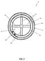
- FIG. 2shows an end view of the distal end of the device of FIG. 1 ;
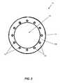
- FIG. 3shows an end view of the proximal end of the device of FIG. 1 ;
- FIGS. 4A and 4Bshow side and end views of the spacer busing of the device of FIG. 1 ;
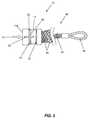
- FIG. 5shows a side view of the device of FIG. 1 .
- FIG. 1a side view of a wire pulling grip 10 is shown.
- the grip 10includes a body 14 having a bore 18 therethrough.
- the body 14is about 1.5 inches in diameter, and the bore 18 through the body is about 1.1 inches in diameter.
- the body 14has a distal end 14 a and a proximal end 14 b.
- a plurality of cams 22are pivotably mounted to the body 14 .
- the cams 22pass through slots 26 in the body 14 to allow the cams to pivot inwardly towards the center of the bore 18 or outwardly to extend out from the body.
- the cams 22are mounted to a rolled ring 30 which is circular in shape and cross section and which forms a pivot for the cams.
- the ring 30is typically made with a small gap to allow the cams 22 to be placed thereon.
- the ringfits in a shoulder or groove 34 which is formed in the body 14 .
- a spacer bushing 38is installed against the ring 30 to hold the ring in place in the body.
- the spacer bushing 38has a tab or post 42 formed on a side thereof which passes through the gap in the ring 30 and fits into a notch 46 formed in the body 14 to prevent rotation of the ring 30 and spacer bushing 38 to prevent loss of the cams 22 .
- a spring clip 50fits against the spacer bushing 38 and into a groove 54 in the body 14 and locks the spacer bushing 38 and ring 30 in place.
- An elastic ring 58(which could be a rubber ring, a circular spring, etc.) is placed around the body 14 in a sloped portion 62 of the body. The slope urges the elastic ring 58 towards the pivot ring 30 , biasing the cams 22 towards the center of the body 14 . Additionally, any friction on the elastic ring 58 while pulling wires through a conduit will also tend to bias the elastic ring 58 towards the pivot ring 30 . If the cams 22 , sloped portion 62 , and elastic ring 58 are appropriately sized, the cams 22 will be biased completely to the center of the bore 18 . In operation, the cams 22 are thus biased towards a wire which is placed through the bore 18 , and are held in contact with the wire. This ensures that the grip 10 does not lose connection with the wire if a pulling force is not applied to the grip 10 , if the pulling force is temporarily lost, or if the grip 10 is placed in any physical orientation.
- the grip 10is pulled in the direction of arrow 66 .
- Resistance to moving the wire which is being pulled by the grip 10will cause the cams 22 to rotate inwardly towards the center of the bore 18 and thus increase the force by which the wire is gripped.
- a high degree of forcecan be reliably applied to the wire as the cams 22 maintain contact and tighten with the application of force.
- the grip 10is connected to a pulling line, a wire is passed through the body 14 through the distal end 14 a of the grip in the direction of arrow 70 , and the grip 10 and wire are pulled in the direction of arrow 66 .
- the grip 10is used in combination with a wire Kellum grip.
- a Kellum gripis a tube made of braided wires. The tube is loosely braided so that it increases diameter when compressed and decreases diameter when stretched. As such, the tube compresses around a wire or cable when placed in tension.
- Conventional Kellum gripsare simply a braided tube of wire with a loop formed on one end to attach to the pulling line. The open end of the tube is placed over the wire, secured to the wire (usually with duct tape or the like), and the Kellum grip is then used to pull the wire.
- the problem with conventional Kellum gripsis the difficulty in securing the open end of the tube to the wire.
- duct tape or the likeis used to secure the open end of the tube to a wire.
- the duct tapecan be difficult to remove afterwards and may leave an undesirable residue on the wire or Kellum grip. Additionally, there is some risk that the duct tape peels off of the grip/wire during a pull and begins to stick to the conduit, which may remove the tape completely and result in the loss of connection between the wire and grip.
- the proximal end 14 b of the body 14has holes 74 and a groove 78 formed therein.
- the holes 74are spaced around the edge of the body 14 and are in communication with the groove 78 to allow wires to be laced therethrough without overly protruding radially from the body 14 .
- the grip 10 with the Kellum grip attached therethroughis shown in FIG. 5 .
- FIG. 2an end view of the distal end 14 a of the grip 10 is shown.
- the spring clip 50 and spacer bushing 38are visible, as well as the cams 22 .
- the camsare biased into the bore 18 in the position shown by the elastic ring 58 . It can be seen how the cams 22 extend almost completely into the center of the bore 18 , and would maintain contact with a wire of approximately 0.125 inch diameter while still accommodating a wire of about 1 inch diameter.
- the grip 10is thus usable with many sizes of wire.
- FIG. 3an end view of the proximal end 14 b of the grip 10 is shown. It can be seen how the holes 74 are spaced around the body 14 . The holes 74 accommodate wires to attach a Kellum grip to the body 14 .
- FIGS. 4A and 4Bside and end views of the spacer bushing 38 are shown.
- the spacer bushing 38includes a post 42 which is received in a notch 46 in the body 14 to prevent rotation of the spacer bushing 38 and pivot ring 30 and loss of the cams 22 .
- the spacer brushing 38may also be made with notches 82 which receive the cams 22 , allowing a closer fit between the spacer bushing 38 and cams 22 .
- FIG. 5a side view of the grip 10 combined with a braided wire tube 86 (such as a Kellum grip) is shown.
- the Kellum grip 86includes a plurality of wires 90 which are braided together into a tube as discussed.
- the wires 90are laced through the holes 74 ( FIG. 1 ) in the grip 10 .
- the groove 78keeps the wires 90 from protruding too far radially from the body 14 .
- the wires 90are typically formed into or connected to a loop 94 which is connected to a pulling line.
- the bore or lumen formed by the braided tube of wiresdoes not typically extend completely through the wires 90 , but is closed at the proximal end of the wires by the loop 94 .
- a wireis passed through the distal end 14 a of the body 14 , passed through the bore 18 ( FIG. 1 ), and is passed through the center of the braided wire grip 86 in the direction of arrow 70 .
- the wireis passed through the center of the braided wires 90 .
- the cams 22biased by the elastic ring 58 , maintain contact with the wire and prevent movement of the wire in the opposite direction.
- the loop 94is then connected to a pulling line and the pulling line is used to pull the grip 10 and wire through a conduit.
- the grip 10secures the distal end 14 a of the Kellum grip 86 to the wire, and both the grip 10 and Kellum grip 86 transmit pulling force to the wire.
- the grip 10 and Kellum grip 86are easily removed from the wire.
- the elastic ring 58is moved adjacent to the groove 78 , allowing the cams 22 to pivot away from the wire.
- the cams 22can then freely pivot out of the bore 18 .
- the grip 10 and Kellum grip 86are simply slid off of the wire in the direction of arrow 70 .
- the grip 10 with Kellum grip 86is thus advantageous as it is easily and quickly installed and removed from a wire while being capable of transmitting well over 10,000 pounds of force to the wire.
- the observed mode of failurehas been the wires 90 breaking, suggesting that nearly any needed pulling force may be supplied if the wires 90 are sized appropriately.
- the grip 10provides an additional level of safety and convenience in use as compared to existing wire pulling grips.
- wire pulling gripswhich use teeth mounted in a tubular body to secure and pull a wire. The wire is inserted into the body and the teeth allow for movement of the wire in only one direction. After the pull is completed, the wire must be cut and passed through the body in the direction of loading.
- These gripsrequire that the person installing the wire cut the wire, remove a cap/pulling eyelet from the body, pass the cut portion of wire through the body, and reattach the cap before starting another pull. This results in lost time. Additionally, if a person accidentally places a tool or finger inside of the body, the object must be similarly removed. Where a finger is placed in the body, it is quite difficult to remove the finger without damage to the finger as the teeth prevent withdrawal of the finger. Thus, the grip 10 is much easier to use than available prior art grips.
- the combination of the grip 10 and the braided wire tube 86provides significant advantages over prior art configurations.
- braided wire tubessuch as Kellum grips
- the Kellum gripis difficult to use.
- duct tape or the likeis typically used to attach the distal end of the Kellum grip to the wire.
- the duct tapehas limited ability to secure the Kellum grip wires to the wire which is being pulled.
- the duct tapemay allow the Kellum grip to slip off of the wire which is pulled if too high of a pulling force is applied.
- the duct tapewill rub against the conduit as the wire is pulled therethrough, which may cause the leading edge of the tape to roll back and expose the adhesive of the tape.
- the present inventionprovides significant advantages when a grip 10 is combined with a Kellum type braided wire tube as shown in FIG. 5 .
- the grip 10provides a secure connection with the wire which will transmit a significant pulling force to the wire. Loss of connection between the grip 10 and the wire is virtually eliminated altogether. Since the grip 10 does not lose connection with the wire, the braided wire grip portion 86 also does not lose connection with the wire. The combined wire pulling grip is thus very reliable as loss of connection with the wire is virtually eliminated.
- the combination of grip 10 and braided wire tube 86transmits a very high degree of force to the wire. While cams and spikes transmit force to a wire at a few points which are close together, the combined grip transmits pulling force to a longer length of the wire at many locations along the wire. Thus, a very high pulling force is transmitted to the wire without concentrating the force on only a few locations on the wire. Placing the entire pulling force at only a few locations on the wire may result in failure of the wire itself. Testing of the grip 10 and braided wire tube 86 as shown in FIG. 5 has demonstrated that failure of the grip occurs at failure of the individual wires 90 rather than failure of the wire which is pulled or a loss of connection between the wire and the pulling grip. Thus, many thousands of pounds of force are reliably transmitted to the wire which is pulled.
- the grip 10 and braided wire tube 86are also significantly easier to use than previous wire pulling grips.
- Previous wire pulling gripshave required a significant amount of work to install and remove the grip from the wire, and often result in a loss in productivity.
- the pulling grip of the present inventionmaximizes pulling strength and reliability while being extremely quick and easy to use.
Landscapes
- Electric Cable Installation (AREA)
Abstract
Description
Claims (20)
Priority Applications (1)
| Application Number | Priority Date | Filing Date | Title |
|---|---|---|---|
| US13/608,057US8459612B2 (en) | 2008-03-05 | 2012-09-10 | Device for gripping and installing wire |
Applications Claiming Priority (3)
| Application Number | Priority Date | Filing Date | Title |
|---|---|---|---|
| US3409508P | 2008-03-05 | 2008-03-05 | |
| US12/398,840US8292267B2 (en) | 2008-03-05 | 2009-03-05 | Device for gripping and installing wire |
| US13/608,057US8459612B2 (en) | 2008-03-05 | 2012-09-10 | Device for gripping and installing wire |
Related Parent Applications (1)
| Application Number | Title | Priority Date | Filing Date |
|---|---|---|---|
| US12/398,840ContinuationUS8292267B2 (en) | 2008-03-05 | 2009-03-05 | Device for gripping and installing wire |
Publications (2)
| Publication Number | Publication Date |
|---|---|
| US20130001491A1 US20130001491A1 (en) | 2013-01-03 |
| US8459612B2true US8459612B2 (en) | 2013-06-11 |
Family
ID=41052667
Family Applications (2)
| Application Number | Title | Priority Date | Filing Date |
|---|---|---|---|
| US12/398,840Active2031-07-17US8292267B2 (en) | 2008-03-05 | 2009-03-05 | Device for gripping and installing wire |
| US13/608,057ActiveUS8459612B2 (en) | 2008-03-05 | 2012-09-10 | Device for gripping and installing wire |
Family Applications Before (1)
| Application Number | Title | Priority Date | Filing Date |
|---|---|---|---|
| US12/398,840Active2031-07-17US8292267B2 (en) | 2008-03-05 | 2009-03-05 | Device for gripping and installing wire |
Country Status (3)
| Country | Link |
|---|---|
| US (2) | US8292267B2 (en) |
| CA (1) | CA2716771C (en) |
| WO (1) | WO2009111659A2 (en) |
Cited By (1)
| Publication number | Priority date | Publication date | Assignee | Title |
|---|---|---|---|---|
| US8757594B2 (en) | 2008-10-23 | 2014-06-24 | Southwire Company, Llc | Pulling jacket for use while installing wires in conduit |
Families Citing this family (19)
| Publication number | Priority date | Publication date | Assignee | Title |
|---|---|---|---|---|
| WO2009111659A2 (en)* | 2008-03-05 | 2009-09-11 | Maxis, Llc | Device for gripping and installing wire |
| US8408520B2 (en) | 2010-04-26 | 2013-04-02 | Southwire Company | Apparatus for pushing conductors into conduit and other structures |
| DE202011052419U1 (en)* | 2011-12-22 | 2012-01-27 | Katimex Cielker Gmbh | Device for pushing and / or pulling a flexurally elastic, shear-stiff rod element |
| US9537293B2 (en) | 2012-02-29 | 2017-01-03 | Encore Wire Corporation | Wire pulling head apparatus with crimp zone indicators and method of using same |
| US9821142B2 (en) | 2013-03-14 | 2017-11-21 | Hollister, Incorporated | Urinary catheters with protective tip |
| US9168354B2 (en)* | 2013-03-14 | 2015-10-27 | Hollister Incorporated | Sleeveless urinary catheters with protective tip |
| ES2547584B1 (en)* | 2014-03-07 | 2016-07-12 | Esteyco S.A.P. | Anchoring means with cable for a horizontal joint, and anchoring procedure with cable for a horizontal joint |
| CN104022470B (en)* | 2014-06-27 | 2016-04-06 | 常州普纳电子科技有限公司 | Phase-compensated cable high accuracy repaiies stripping device |
| GB2561261B (en) | 2017-06-21 | 2019-05-08 | C Ling Ltd | Pull-in head assembly |
| GB2561259B (en) | 2017-06-21 | 2019-05-08 | C Ling Ltd | Pull-in head assembly |
| GB2561260B (en) | 2017-06-21 | 2019-05-08 | C Ling Ltd | Pull-in head assembly |
| CN107487420A (en)* | 2017-08-11 | 2017-12-19 | 上海船舶研究设计院(中国船舶工业集团公司第六0四研究院) | Tensile force correcting mechanism, installation method, umbilical paving system and ship |
| US10461514B2 (en) | 2017-10-06 | 2019-10-29 | Quick Fitting, Inc. | Cable securing device |
| US11018481B1 (en) | 2020-01-29 | 2021-05-25 | Quick Fitting Holding Company, Llc | Cable securing device |
| US11967806B2 (en)* | 2020-05-05 | 2024-04-23 | Promethean Innovations, Llc | Apparatus and method for installing wire behind existing walls |
| WO2021225939A1 (en)* | 2020-05-05 | 2021-11-11 | Kaleshnik Christopher | Apparatus and method for installing wire behind existing walls |
| JP7102570B1 (en)* | 2021-03-31 | 2022-07-19 | 住友理工株式会社 | Sliding bush |
| US11639745B2 (en) | 2021-07-08 | 2023-05-02 | Quick Fitting Holding Company, Llc | Self-locking cable securing device, assembly and method |
| US11428295B1 (en) | 2021-07-09 | 2022-08-30 | Quick Fitting Holding Company, Llc | Self-locking cable securing device with cartridge and locking element |
Citations (65)
| Publication number | Priority date | Publication date | Assignee | Title |
|---|---|---|---|---|
| US321130A (en) | 1885-06-30 | Tebeitoby | ||
| US564012A (en) | 1896-07-14 | Tackle-block | ||
| US690438A (en) | 1901-09-20 | 1902-01-07 | William C Jones | Wire-grip. |
| US707732A (en) | 1901-12-12 | 1902-08-26 | Swarm Fence Builder Tool Company | Wire stretcher. |
| US749760A (en) | 1904-01-19 | Pipe or rod holder | ||
| US842329A (en) | 1906-05-09 | 1907-01-29 | Horatio T Mcclean | Wire-grip. |
| US1039727A (en) | 1911-07-18 | 1912-10-01 | Yale & Towne Mfg Co | Grapple. |
| US1265141A (en) | 1917-12-24 | 1918-05-07 | William Trippe | Clambing-tool. |
| US1272392A (en) | 1917-03-31 | 1918-07-16 | Thomas J Craven | Cable-grip. |
| US1504087A (en) | 1924-01-05 | 1924-08-05 | Brady Judson Roy | Wire-line clamp |
| US1520716A (en) | 1924-03-08 | 1924-12-30 | John G Judd | Wire gripper |
| US1634422A (en) | 1926-11-01 | 1927-07-05 | Julie D Holmes | Rod clamp |
| US1720037A (en) | 1927-12-06 | 1929-07-09 | Raymond R Entwistle | Grip for fish tape |
| US1760885A (en) | 1928-02-08 | 1930-06-03 | Prelesnik Anton | Gripping device |
| US2146575A (en) | 1937-05-18 | 1939-02-07 | Hefftner Max | Clamp |
| US2322464A (en) | 1940-03-18 | 1943-06-22 | Earl A Mckee | Grease retainer puller and the like |
| US2614801A (en) | 1950-07-26 | 1952-10-21 | Aircraft Hardware Mfg Co Inc | Wire holding and prestressing device |
| US2697872A (en) | 1950-10-05 | 1954-12-28 | Robert S Armstrong | Tube pulling device |
| US2736532A (en) | 1954-04-23 | 1956-02-28 | Elmer V Hughes | Tool for pushing or pulling fish tape through a conduit |
| US2766501A (en) | 1951-05-22 | 1956-10-16 | Kellems Company | Cable grips |
| US2853335A (en) | 1953-11-24 | 1958-09-23 | James C Mogle | Fishing tools |
| US2935299A (en) | 1957-12-30 | 1960-05-03 | Jansen Gerhart | Clamp nut apparatus |
| US2950525A (en) | 1958-08-26 | 1960-08-30 | Edward J Duncan | Tube puller |
| US3252210A (en) | 1964-02-28 | 1966-05-24 | Roy N Bowden | Tool for removing hydraulic valve lifters |
| US3312128A (en) | 1965-05-07 | 1967-04-04 | Lawrence W Wasson | Wire gripper |
| US3492032A (en) | 1968-08-13 | 1970-01-27 | Wyoming Investment Co Inc | Tension cap |
| US3659890A (en) | 1970-08-05 | 1972-05-02 | Renfroe & Sons J C | Lifting clamp |
| US3709546A (en) | 1970-07-20 | 1973-01-09 | D Vaughan | Conduit puller |
| US3730129A (en) | 1971-01-25 | 1973-05-01 | Seahorse Spars And Equipment L | Extruded cam cleat |
| US3776586A (en) | 1972-02-09 | 1973-12-04 | Uddemann Byggteknik Ab | Gripping device |
| US4015873A (en) | 1975-12-22 | 1977-04-05 | The United States Of America As Represented By The Secretary Of The Navy | Retriever |
| US4019715A (en) | 1976-06-09 | 1977-04-26 | Western Electric Company, Inc. | Cable block |
| US4077094A (en) | 1976-09-17 | 1978-03-07 | Swager William E | Clamping device for a rope, cable, annular bar, or the like |
| US4214362A (en) | 1977-11-26 | 1980-07-29 | Production Engineering Research Association Of Great Britain | Gripping means |
| US4312124A (en) | 1979-11-27 | 1982-01-26 | Westinghouse Electric Corp. | Multiple tube pulling apparatus |
| US4354705A (en) | 1979-10-16 | 1982-10-19 | Harvey Hubbell Incorporated | Cable grips |
| US4368910A (en) | 1980-12-08 | 1983-01-18 | Harvey Hubbell Incorporated | Grip for pulling fiber optic cable and method of inserting the cable into the grip |
| US4377956A (en) | 1980-07-22 | 1983-03-29 | Dennis Cooper | Pipe extractor tool |
| US4575032A (en) | 1985-04-04 | 1986-03-11 | Taylor Peter C | Rock climbing adjustable chock |
| US4659126A (en) | 1984-03-21 | 1987-04-21 | Illinois Bell Telephone Company | Duct pulling tool |
| US4736971A (en) | 1986-11-14 | 1988-04-12 | Acme Machine Works, Inc. | Billet grab |
| US4736978A (en) | 1983-09-06 | 1988-04-12 | Katimex-Cielker Gmbh | Coupling device for inserting cables into cable-protecting pipes |
| US4746099A (en) | 1987-03-09 | 1988-05-24 | Lopes Edward L | Cam action fish tape puller |
| US4843687A (en) | 1989-01-17 | 1989-07-04 | Kroepelin Jr Willis F | Hand held rope cleat |
| US5015023A (en) | 1989-12-11 | 1991-05-14 | Hall Gaddis G | Automatic cable gripping device |
| US5022633A (en) | 1989-11-15 | 1991-06-11 | Lopes Edward L | One-handed cam action fish tape puller |
| US5127853A (en) | 1989-11-08 | 1992-07-07 | Raychem Corporation | Feedthrough coaxial cable connector |
| US5199146A (en) | 1990-07-25 | 1993-04-06 | Snap-On Tools Corporation | Tensioning and crimping tool |
| US5245730A (en) | 1992-08-12 | 1993-09-21 | Martin Horace J | Rope connector having quick engaging and releasing means |
| US5513555A (en) | 1994-01-21 | 1996-05-07 | Michael J. Plank | Quick-release cam lock with locking pin |
| US5548873A (en) | 1993-12-08 | 1996-08-27 | Macias; Isreal A. | Self-locking cleat for rope, cable and the like |
| US5984273A (en) | 1998-05-15 | 1999-11-16 | Ray; Brian N. | Wire puller |
| US5988719A (en) | 1998-03-05 | 1999-11-23 | Aeroquip-Vickers, Inc. | Internal pipe pulling device |
| US6178604B1 (en) | 1997-07-28 | 2001-01-30 | Raymond P. Pennoyer, Jr. | Clothesline line tightener |
| US6286815B1 (en) | 1998-05-15 | 2001-09-11 | Brian N. Ray | Wire puller |
| US6416040B1 (en) | 2001-07-09 | 2002-07-09 | William Bergman | Electrician's fish tape reel assembly and fish tape winder-puller |
| US6446531B1 (en) | 2000-03-20 | 2002-09-10 | Louie V. Colombani | Sprinkler riser extraction insertion tool |
| US6682050B1 (en) | 1998-05-15 | 2004-01-27 | Brian N. Ray | Wire puller |
| US6883782B2 (en) | 2002-08-30 | 2005-04-26 | Bendyco Incorporated | Cable clamping apparatus and method |
| US6974169B1 (en) | 2004-07-12 | 2005-12-13 | Federal-Mogul World Wide, Inc. | Pulling grip with shroud |
| US7146697B2 (en) | 2004-04-06 | 2006-12-12 | Honeywell International, Inc. | Seal removal tool |
| US20070221896A1 (en) | 2006-02-28 | 2007-09-27 | Jordan Michael C | Wire puller and conduit adapter |
| US7478794B1 (en)* | 2006-09-26 | 2009-01-20 | Rectorseal Corporation | Apparatus and methods for gripping an elongated item |
| US20090065663A1 (en) | 2007-09-11 | 2009-03-12 | David Jordan | Combination stand and jack for wire spools |
| US20090224220A1 (en)* | 2008-03-05 | 2009-09-10 | David Jordan | Device for gripping and installing wire |
Family Cites Families (11)
| Publication number | Priority date | Publication date | Assignee | Title |
|---|---|---|---|---|
| US524035A (en) | 1894-08-07 | Cork-puller | ||
| US1272087A (en)* | 1917-12-28 | 1918-07-09 | John Pochopien | Bath-tub cabinet. |
| US2231919A (en) | 1939-11-03 | 1941-02-18 | Bell Telephone Labor Inc | Grappling device |
| US3038754A (en) | 1960-04-04 | 1962-06-12 | Robert E Petersen | Cable and conduit puller |
| US3727967A (en) | 1971-06-17 | 1973-04-17 | Inst Proiectari Si Cercetari P | Universal overshot |
| US3906619A (en) | 1973-10-04 | 1975-09-23 | Frank E Shaffer | Method for securing cable puller connector to a cable |
| US4453291A (en) | 1982-06-21 | 1984-06-12 | Harvey Hubbell Incorporated | Grip for pulling fiber optic cable |
| US5283930A (en) | 1993-02-12 | 1994-02-08 | American Cord & Webbing Co., Inc. | Cord clamp with hasp for folded cords and the like |
| US5868060A (en) | 1994-01-24 | 1999-02-09 | Speed Shore Corp. | Quick-release cam lock |
| EP1046836A3 (en) | 1999-04-20 | 2002-03-13 | Peter John Stenstrom | Device for displacing a pipe etc. |
| US6695290B1 (en) | 1999-10-29 | 2004-02-24 | O'connell Timothy E. | Lifting jack accessory |
- 2009
- 2009-03-05WOPCT/US2009/036224patent/WO2009111659A2/enactiveApplication Filing
- 2009-03-05CACA2716771Apatent/CA2716771C/enactiveActive
- 2009-03-05USUS12/398,840patent/US8292267B2/enactiveActive
- 2012
- 2012-09-10USUS13/608,057patent/US8459612B2/enactiveActive
Patent Citations (68)
| Publication number | Priority date | Publication date | Assignee | Title |
|---|---|---|---|---|
| US321130A (en) | 1885-06-30 | Tebeitoby | ||
| US564012A (en) | 1896-07-14 | Tackle-block | ||
| US749760A (en) | 1904-01-19 | Pipe or rod holder | ||
| US690438A (en) | 1901-09-20 | 1902-01-07 | William C Jones | Wire-grip. |
| US707732A (en) | 1901-12-12 | 1902-08-26 | Swarm Fence Builder Tool Company | Wire stretcher. |
| US842329A (en) | 1906-05-09 | 1907-01-29 | Horatio T Mcclean | Wire-grip. |
| US1039727A (en) | 1911-07-18 | 1912-10-01 | Yale & Towne Mfg Co | Grapple. |
| US1272392A (en) | 1917-03-31 | 1918-07-16 | Thomas J Craven | Cable-grip. |
| US1265141A (en) | 1917-12-24 | 1918-05-07 | William Trippe | Clambing-tool. |
| US1504087A (en) | 1924-01-05 | 1924-08-05 | Brady Judson Roy | Wire-line clamp |
| US1520716A (en) | 1924-03-08 | 1924-12-30 | John G Judd | Wire gripper |
| US1634422A (en) | 1926-11-01 | 1927-07-05 | Julie D Holmes | Rod clamp |
| US1720037A (en) | 1927-12-06 | 1929-07-09 | Raymond R Entwistle | Grip for fish tape |
| US1760885A (en) | 1928-02-08 | 1930-06-03 | Prelesnik Anton | Gripping device |
| US2146575A (en) | 1937-05-18 | 1939-02-07 | Hefftner Max | Clamp |
| US2322464A (en) | 1940-03-18 | 1943-06-22 | Earl A Mckee | Grease retainer puller and the like |
| US2614801A (en) | 1950-07-26 | 1952-10-21 | Aircraft Hardware Mfg Co Inc | Wire holding and prestressing device |
| US2697872A (en) | 1950-10-05 | 1954-12-28 | Robert S Armstrong | Tube pulling device |
| US2766501A (en) | 1951-05-22 | 1956-10-16 | Kellems Company | Cable grips |
| US2853335A (en) | 1953-11-24 | 1958-09-23 | James C Mogle | Fishing tools |
| US2736532A (en) | 1954-04-23 | 1956-02-28 | Elmer V Hughes | Tool for pushing or pulling fish tape through a conduit |
| US2935299A (en) | 1957-12-30 | 1960-05-03 | Jansen Gerhart | Clamp nut apparatus |
| US2950525A (en) | 1958-08-26 | 1960-08-30 | Edward J Duncan | Tube puller |
| US3252210A (en) | 1964-02-28 | 1966-05-24 | Roy N Bowden | Tool for removing hydraulic valve lifters |
| US3312128A (en) | 1965-05-07 | 1967-04-04 | Lawrence W Wasson | Wire gripper |
| US3492032A (en) | 1968-08-13 | 1970-01-27 | Wyoming Investment Co Inc | Tension cap |
| US3709546A (en) | 1970-07-20 | 1973-01-09 | D Vaughan | Conduit puller |
| US3659890A (en) | 1970-08-05 | 1972-05-02 | Renfroe & Sons J C | Lifting clamp |
| US3730129A (en) | 1971-01-25 | 1973-05-01 | Seahorse Spars And Equipment L | Extruded cam cleat |
| US3776586A (en) | 1972-02-09 | 1973-12-04 | Uddemann Byggteknik Ab | Gripping device |
| US4015873A (en) | 1975-12-22 | 1977-04-05 | The United States Of America As Represented By The Secretary Of The Navy | Retriever |
| US4019715A (en) | 1976-06-09 | 1977-04-26 | Western Electric Company, Inc. | Cable block |
| US4077094A (en) | 1976-09-17 | 1978-03-07 | Swager William E | Clamping device for a rope, cable, annular bar, or the like |
| US4214362A (en) | 1977-11-26 | 1980-07-29 | Production Engineering Research Association Of Great Britain | Gripping means |
| US4354705A (en) | 1979-10-16 | 1982-10-19 | Harvey Hubbell Incorporated | Cable grips |
| US4312124A (en) | 1979-11-27 | 1982-01-26 | Westinghouse Electric Corp. | Multiple tube pulling apparatus |
| US4377956A (en) | 1980-07-22 | 1983-03-29 | Dennis Cooper | Pipe extractor tool |
| US4368910A (en) | 1980-12-08 | 1983-01-18 | Harvey Hubbell Incorporated | Grip for pulling fiber optic cable and method of inserting the cable into the grip |
| US4736978A (en) | 1983-09-06 | 1988-04-12 | Katimex-Cielker Gmbh | Coupling device for inserting cables into cable-protecting pipes |
| US4659126A (en) | 1984-03-21 | 1987-04-21 | Illinois Bell Telephone Company | Duct pulling tool |
| US4575032A (en) | 1985-04-04 | 1986-03-11 | Taylor Peter C | Rock climbing adjustable chock |
| US4736971A (en) | 1986-11-14 | 1988-04-12 | Acme Machine Works, Inc. | Billet grab |
| US4746099A (en) | 1987-03-09 | 1988-05-24 | Lopes Edward L | Cam action fish tape puller |
| US4843687A (en) | 1989-01-17 | 1989-07-04 | Kroepelin Jr Willis F | Hand held rope cleat |
| US5127853A (en) | 1989-11-08 | 1992-07-07 | Raychem Corporation | Feedthrough coaxial cable connector |
| US5022633A (en) | 1989-11-15 | 1991-06-11 | Lopes Edward L | One-handed cam action fish tape puller |
| US5015023A (en) | 1989-12-11 | 1991-05-14 | Hall Gaddis G | Automatic cable gripping device |
| US5199146A (en) | 1990-07-25 | 1993-04-06 | Snap-On Tools Corporation | Tensioning and crimping tool |
| US5245730A (en) | 1992-08-12 | 1993-09-21 | Martin Horace J | Rope connector having quick engaging and releasing means |
| US5548873A (en) | 1993-12-08 | 1996-08-27 | Macias; Isreal A. | Self-locking cleat for rope, cable and the like |
| US5513555A (en) | 1994-01-21 | 1996-05-07 | Michael J. Plank | Quick-release cam lock with locking pin |
| US6178604B1 (en) | 1997-07-28 | 2001-01-30 | Raymond P. Pennoyer, Jr. | Clothesline line tightener |
| US5988719A (en) | 1998-03-05 | 1999-11-23 | Aeroquip-Vickers, Inc. | Internal pipe pulling device |
| US5984273A (en) | 1998-05-15 | 1999-11-16 | Ray; Brian N. | Wire puller |
| US6286815B1 (en) | 1998-05-15 | 2001-09-11 | Brian N. Ray | Wire puller |
| US6682050B1 (en) | 1998-05-15 | 2004-01-27 | Brian N. Ray | Wire puller |
| US6446531B1 (en) | 2000-03-20 | 2002-09-10 | Louie V. Colombani | Sprinkler riser extraction insertion tool |
| US6416040B1 (en) | 2001-07-09 | 2002-07-09 | William Bergman | Electrician's fish tape reel assembly and fish tape winder-puller |
| US7128306B2 (en) | 2002-08-30 | 2006-10-31 | Rectorseal Corporation | Cable clamping apparatus and method |
| US6883782B2 (en) | 2002-08-30 | 2005-04-26 | Bendyco Incorporated | Cable clamping apparatus and method |
| US7246789B2 (en) | 2002-08-30 | 2007-07-24 | Rectorseal Corporation | Cable clamping apparatus and method |
| US7146697B2 (en) | 2004-04-06 | 2006-12-12 | Honeywell International, Inc. | Seal removal tool |
| US6974169B1 (en) | 2004-07-12 | 2005-12-13 | Federal-Mogul World Wide, Inc. | Pulling grip with shroud |
| US20070221896A1 (en) | 2006-02-28 | 2007-09-27 | Jordan Michael C | Wire puller and conduit adapter |
| US7478794B1 (en)* | 2006-09-26 | 2009-01-20 | Rectorseal Corporation | Apparatus and methods for gripping an elongated item |
| US20090065663A1 (en) | 2007-09-11 | 2009-03-12 | David Jordan | Combination stand and jack for wire spools |
| US20090224220A1 (en)* | 2008-03-05 | 2009-09-10 | David Jordan | Device for gripping and installing wire |
| US8292267B2 (en)* | 2008-03-05 | 2012-10-23 | Southwire Company | Device for gripping and installing wire |
Non-Patent Citations (3)
| Title |
|---|
| International Search Report & Written Opinion dated Nov. 17, 2009 in PCT Application No. PCT/09/36224. |
| U.S. Notice of Allowance dated Jun. 7, 2012 in U.S. Appl. No. 12/398,840. |
| U.S. Office Action dated Feb. 16, 2012 in U.S. Appl. No. 12/398,840. |
Cited By (1)
| Publication number | Priority date | Publication date | Assignee | Title |
|---|---|---|---|---|
| US8757594B2 (en) | 2008-10-23 | 2014-06-24 | Southwire Company, Llc | Pulling jacket for use while installing wires in conduit |
Also Published As
| Publication number | Publication date |
|---|---|
| CA2716771C (en) | 2016-02-09 |
| US8292267B2 (en) | 2012-10-23 |
| WO2009111659A2 (en) | 2009-09-11 |
| US20130001491A1 (en) | 2013-01-03 |
| CA2716771A1 (en) | 2009-09-11 |
| US20090224220A1 (en) | 2009-09-10 |
| WO2009111659A3 (en) | 2010-01-07 |
Similar Documents
| Publication | Publication Date | Title |
|---|---|---|
| US8459612B2 (en) | Device for gripping and installing wire | |
| US20110069931A1 (en) | Strain Relief Device and Method for Fiber Optic Cables | |
| US8757594B2 (en) | Pulling jacket for use while installing wires in conduit | |
| US9120656B2 (en) | Rope anchor for a winch | |
| US6100472A (en) | Cable locking and sealing device | |
| US9065262B2 (en) | Fish tape leader with quick change coupling | |
| EP3642920A1 (en) | Pull-in head assembly | |
| TW201909503A (en) | Pull-in head assembly | |
| EP3642919A1 (en) | Pull-in head assembly | |
| US10437002B2 (en) | Universal cable installation tool | |
| AU2007305309B2 (en) | Fiber optic cable assemblies including remote tether release apparatus | |
| US6418592B1 (en) | Rope gripper | |
| US20030012621A1 (en) | Cotter clip | |
| EP2941331B1 (en) | Improved apparatus and method for insertion of gaskets | |
| KR100604575B1 (en) | Cable Gripping Device and Cable Traction Device | |
| JP4022408B2 (en) | Cable laying device | |
| AU2020426002B2 (en) | Cable securing device | |
| US20090057010A1 (en) | Cover for terminated cables | |
| EP2133614B1 (en) | Pipe coupling | |
| KR100383429B1 (en) | Apparatus for pulling a bundle of cables | |
| WO2024161305A1 (en) | Cable clamp and attachment means | |
| KR200298230Y1 (en) | apparatus for fixing electric wires | |
| JP2006047915A (en) | Safety separator for optical drop cable | |
| KR20050070304A (en) | Band clip | |
| JP2009044813A (en) | Holding tool for wire draw-in |
Legal Events
| Date | Code | Title | Description |
|---|---|---|---|
| AS | Assignment | Owner name:MAXIS, LLC, ARIZONA Free format text:ASSIGNMENT OF ASSIGNORS INTEREST;ASSIGNORS:JORDAN, DAVID;JORDAN, MICHAEL;REEL/FRAME:030317/0398 Effective date:20090827 Owner name:SOUTHWIRE COMPANY, GEORGIA Free format text:ASSIGNMENT OF ASSIGNORS INTEREST;ASSIGNOR:MAXIS, LLC;REEL/FRAME:030317/0553 Effective date:20090918 | |
| STCF | Information on status: patent grant | Free format text:PATENTED CASE | |
| AS | Assignment | Owner name:BANK OF AMERICA, N.A., AS COLLATERAL AGENT, NORTH CAROLINA Free format text:SECURITY AGREEMENT;ASSIGNORS:SOUTHWIRE COMPANY, LLC;COLEMAN CABLE, INC.;TECHNOLOGY RESEARCH CORPORATION;REEL/FRAME:032251/0277 Effective date:20140211 Owner name:BANK OF AMERICA, N.A., AS COLLATERAL AGENT, NORTH Free format text:SECURITY AGREEMENT;ASSIGNORS:SOUTHWIRE COMPANY, LLC;COLEMAN CABLE, INC.;TECHNOLOGY RESEARCH CORPORATION;REEL/FRAME:032251/0277 Effective date:20140211 | |
| AS | Assignment | Owner name:WELLS FARGO BANK, NATIONAL ASSOCIATION, AS COLLATERAL AGENT, GEORGIA Free format text:GRANT OF SECURITY INTEREST IN PATENT RIGHTS;ASSIGNORS:SOUTHWIRE COMPANY, LLC;COLEMAN CABLE, INC.;TECHNOLOGY RESEARCH CORPORATION;REEL/FRAME:032308/0469 Effective date:20140211 Owner name:WELLS FARGO BANK, NATIONAL ASSOCIATION, AS COLLATE Free format text:GRANT OF SECURITY INTEREST IN PATENT RIGHTS;ASSIGNORS:SOUTHWIRE COMPANY, LLC;COLEMAN CABLE, INC.;TECHNOLOGY RESEARCH CORPORATION;REEL/FRAME:032308/0469 Effective date:20140211 | |
| AS | Assignment | Owner name:SOUTHWIRE COMPANY, LLC, GEORGIA Free format text:CERTIFICATE OF CONVERSION;ASSIGNOR:SOUTHWIRE COMPANY;REEL/FRAME:032835/0408 Effective date:20140205 | |
| FPAY | Fee payment | Year of fee payment:4 | |
| MAFP | Maintenance fee payment | Free format text:PAYMENT OF MAINTENANCE FEE, 8TH YEAR, LARGE ENTITY (ORIGINAL EVENT CODE: M1552); ENTITY STATUS OF PATENT OWNER: LARGE ENTITY Year of fee payment:8 | |
| AS | Assignment | Owner name:WIIP, INC., CANADA Free format text:TERMINATION AND RELEASE OF INTELLECTUAL PROPERTY SECURITY AGREEMENTS;ASSIGNOR:BANK OF AMERICA, N.A., AS AGENT;REEL/FRAME:069235/0104 Effective date:20241022 Owner name:OBI PARTNERS, LLC, GEORGIA Free format text:TERMINATION AND RELEASE OF INTELLECTUAL PROPERTY SECURITY AGREEMENTS;ASSIGNOR:BANK OF AMERICA, N.A., AS AGENT;REEL/FRAME:069235/0104 Effective date:20241022 Owner name:TOPAZ LIGHTING COMPANY LLC, GEORGIA Free format text:TERMINATION AND RELEASE OF INTELLECTUAL PROPERTY SECURITY AGREEMENTS;ASSIGNOR:BANK OF AMERICA, N.A., AS AGENT;REEL/FRAME:069235/0104 Effective date:20241022 Owner name:UNITED COPPER INDUSTRIES, LLC, DELAWARE Free format text:TERMINATION AND RELEASE OF INTELLECTUAL PROPERTY SECURITY AGREEMENTS;ASSIGNOR:BANK OF AMERICA, N.A., AS AGENT;REEL/FRAME:069235/0104 Effective date:20241022 Owner name:TAPPAN WIRE & CABLE, LLC, NEW YORK Free format text:TERMINATION AND RELEASE OF INTELLECTUAL PROPERTY SECURITY AGREEMENTS;ASSIGNOR:BANK OF AMERICA, N.A., AS AGENT;REEL/FRAME:069235/0104 Effective date:20241022 Owner name:WATTEREDGE, LLC, OHIO Free format text:TERMINATION AND RELEASE OF INTELLECTUAL PROPERTY SECURITY AGREEMENTS;ASSIGNOR:BANK OF AMERICA, N.A., AS AGENT;REEL/FRAME:069235/0104 Effective date:20241022 Owner name:NOVINIUM, LLC, GEORGIA Free format text:TERMINATION AND RELEASE OF INTELLECTUAL PROPERTY SECURITY AGREEMENTS;ASSIGNOR:BANK OF AMERICA, N.A., AS AGENT;REEL/FRAME:069235/0104 Effective date:20241022 Owner name:MADISON ELECTRIC PRODUCTS, LLC, OHIO Free format text:TERMINATION AND RELEASE OF INTELLECTUAL PROPERTY SECURITY AGREEMENTS;ASSIGNOR:BANK OF AMERICA, N.A., AS AGENT;REEL/FRAME:069235/0104 Effective date:20241022 Owner name:SUMNER MANUFACTURING COMPANY, LLC, DELAWARE Free format text:TERMINATION AND RELEASE OF INTELLECTUAL PROPERTY SECURITY AGREEMENTS;ASSIGNOR:BANK OF AMERICA, N.A., AS AGENT;REEL/FRAME:069235/0104 Effective date:20241022 Owner name:TECHNOLOGY RESEARCH, LLC (F/K/A TECHNOLOGY RESEARCH CORPORATION), FLORIDA Free format text:TERMINATION AND RELEASE OF INTELLECTUAL PROPERTY SECURITY AGREEMENTS;ASSIGNOR:BANK OF AMERICA, N.A., AS AGENT;REEL/FRAME:069235/0104 Effective date:20241022 Owner name:COLEMAN CABLE, LLC (F/K/A COLEMAN CABLE, INC.), ILLINOIS Free format text:TERMINATION AND RELEASE OF INTELLECTUAL PROPERTY SECURITY AGREEMENTS;ASSIGNOR:BANK OF AMERICA, N.A., AS AGENT;REEL/FRAME:069235/0104 Effective date:20241022 Owner name:SOUTHWIRE COMPANY, LLC, GEORGIA Free format text:TERMINATION AND RELEASE OF INTELLECTUAL PROPERTY SECURITY AGREEMENTS;ASSIGNOR:BANK OF AMERICA, N.A., AS AGENT;REEL/FRAME:069235/0104 Effective date:20241022 | |
| MAFP | Maintenance fee payment | Free format text:PAYMENT OF MAINTENANCE FEE, 12TH YEAR, LARGE ENTITY (ORIGINAL EVENT CODE: M1553); ENTITY STATUS OF PATENT OWNER: LARGE ENTITY Year of fee payment:12 | |
| AS | Assignment | Owner name:SOUTHWIRE COMPANY, LLC, GEORGIA Free format text:RELEASE BY SECURED PARTY;ASSIGNOR:WELLS FARGO BANK, NATIONAL ASSOCIATION;REEL/FRAME:072299/0141 Effective date:20250730 Owner name:COLEMAN CABLE, LLC, GEORGIA Free format text:RELEASE BY SECURED PARTY;ASSIGNOR:WELLS FARGO BANK, NATIONAL ASSOCIATION;REEL/FRAME:072299/0141 Effective date:20250730 Owner name:TECHNOLOGY RESEARCH, LLC, GEORGIA Free format text:RELEASE BY SECURED PARTY;ASSIGNOR:WELLS FARGO BANK, NATIONAL ASSOCIATION;REEL/FRAME:072299/0141 Effective date:20250730 Owner name:SUMNER MANUFACTURING COMPANY, LLC, GEORGIA Free format text:RELEASE BY SECURED PARTY;ASSIGNOR:WELLS FARGO BANK, NATIONAL ASSOCIATION;REEL/FRAME:072299/0141 Effective date:20250730 Owner name:MADISON ELECTRIC PRODUCTS, LLC, GEORGIA Free format text:RELEASE BY SECURED PARTY;ASSIGNOR:WELLS FARGO BANK, NATIONAL ASSOCIATION;REEL/FRAME:072299/0141 Effective date:20250730 Owner name:NOVINIUM, LLC, GEORGIA Free format text:RELEASE BY SECURED PARTY;ASSIGNOR:WELLS FARGO BANK, NATIONAL ASSOCIATION;REEL/FRAME:072299/0141 Effective date:20250730 Owner name:NOVINIUM HOLDINGS, INC., GEORGIA Free format text:RELEASE BY SECURED PARTY;ASSIGNOR:WELLS FARGO BANK, NATIONAL ASSOCIATION;REEL/FRAME:072299/0141 Effective date:20250730 Owner name:WATTEREDGE, LLC, GEORGIA Free format text:RELEASE BY SECURED PARTY;ASSIGNOR:WELLS FARGO BANK, NATIONAL ASSOCIATION;REEL/FRAME:072299/0141 Effective date:20250730 Owner name:TAPPAN WIRE & CABLE, LLC, GEORGIA Free format text:RELEASE BY SECURED PARTY;ASSIGNOR:WELLS FARGO BANK, NATIONAL ASSOCIATION;REEL/FRAME:072299/0141 Effective date:20250730 Owner name:UNITED COPPER INDUSTRIES, LLC, GEORGIA Free format text:RELEASE BY SECURED PARTY;ASSIGNOR:WELLS FARGO BANK, NATIONAL ASSOCIATION;REEL/FRAME:072299/0141 Effective date:20250730 Owner name:TOPAZ LIGHTING COMPANY LLC, GEORGIA Free format text:RELEASE BY SECURED PARTY;ASSIGNOR:WELLS FARGO BANK, NATIONAL ASSOCIATION;REEL/FRAME:072299/0141 Effective date:20250730 Owner name:OBI PARTNERS, LLC, GEORGIA Free format text:RELEASE BY SECURED PARTY;ASSIGNOR:WELLS FARGO BANK, NATIONAL ASSOCIATION;REEL/FRAME:072299/0141 Effective date:20250730 Owner name:WIIP, INC., GEORGIA Free format text:RELEASE BY SECURED PARTY;ASSIGNOR:WELLS FARGO BANK, NATIONAL ASSOCIATION;REEL/FRAME:072299/0141 Effective date:20250730 |