US8459418B2 - Bicycle fork having lock-out, blow-off, and adjustable blow-off threshold - Google Patents
Bicycle fork having lock-out, blow-off, and adjustable blow-off thresholdDownload PDFInfo
- Publication number
- US8459418B2 US8459418B2US13/250,886US201113250886AUS8459418B2US 8459418 B2US8459418 B2US 8459418B2US 201113250886 AUS201113250886 AUS 201113250886AUS 8459418 B2US8459418 B2US 8459418B2
- Authority
- US
- United States
- Prior art keywords
- compression
- spring
- rebound
- fork
- piston
- Prior art date
- Legal status (The legal status is an assumption and is not a legal conclusion. Google has not performed a legal analysis and makes no representation as to the accuracy of the status listed.)
- Expired - Lifetime
Links
Images


Classifications
- F—MECHANICAL ENGINEERING; LIGHTING; HEATING; WEAPONS; BLASTING
- F16—ENGINEERING ELEMENTS AND UNITS; GENERAL MEASURES FOR PRODUCING AND MAINTAINING EFFECTIVE FUNCTIONING OF MACHINES OR INSTALLATIONS; THERMAL INSULATION IN GENERAL
- F16F—SPRINGS; SHOCK-ABSORBERS; MEANS FOR DAMPING VIBRATION
- F16F9/00—Springs, vibration-dampers, shock-absorbers, or similarly-constructed movement-dampers using a fluid or the equivalent as damping medium
- F16F9/32—Details
- F16F9/44—Means on or in the damper for manual or non-automatic adjustment; such means combined with temperature correction
- B—PERFORMING OPERATIONS; TRANSPORTING
- B60—VEHICLES IN GENERAL
- B60G—VEHICLE SUSPENSION ARRANGEMENTS
- B60G17/00—Resilient suspensions having means for adjusting the spring or vibration-damper characteristics, for regulating the distance between a supporting surface and a sprung part of vehicle or for locking suspension during use to meet varying vehicular or surface conditions, e.g. due to speed or load
- B60G17/06—Characteristics of dampers, e.g. mechanical dampers
- B60G17/08—Characteristics of fluid dampers
- B—PERFORMING OPERATIONS; TRANSPORTING
- B62—LAND VEHICLES FOR TRAVELLING OTHERWISE THAN ON RAILS
- B62K—CYCLES; CYCLE FRAMES; CYCLE STEERING DEVICES; RIDER-OPERATED TERMINAL CONTROLS SPECIALLY ADAPTED FOR CYCLES; CYCLE AXLE SUSPENSIONS; CYCLE SIDE-CARS, FORECARS, OR THE LIKE
- B62K25/00—Axle suspensions
- B62K25/04—Axle suspensions for mounting axles resiliently on cycle frame or fork
- B62K25/06—Axle suspensions for mounting axles resiliently on cycle frame or fork with telescopic fork, e.g. including auxiliary rocking arms
- B62K25/08—Axle suspensions for mounting axles resiliently on cycle frame or fork with telescopic fork, e.g. including auxiliary rocking arms for front wheel
- B—PERFORMING OPERATIONS; TRANSPORTING
- B62—LAND VEHICLES FOR TRAVELLING OTHERWISE THAN ON RAILS
- B62K—CYCLES; CYCLE FRAMES; CYCLE STEERING DEVICES; RIDER-OPERATED TERMINAL CONTROLS SPECIALLY ADAPTED FOR CYCLES; CYCLE AXLE SUSPENSIONS; CYCLE SIDE-CARS, FORECARS, OR THE LIKE
- B62K25/00—Axle suspensions
- B62K25/04—Axle suspensions for mounting axles resiliently on cycle frame or fork
- B62K25/28—Axle suspensions for mounting axles resiliently on cycle frame or fork with pivoted chain-stay
- B62K25/286—Axle suspensions for mounting axles resiliently on cycle frame or fork with pivoted chain-stay the shock absorber being connected to the chain-stay via a linkage mechanism
- F—MECHANICAL ENGINEERING; LIGHTING; HEATING; WEAPONS; BLASTING
- F16—ENGINEERING ELEMENTS AND UNITS; GENERAL MEASURES FOR PRODUCING AND MAINTAINING EFFECTIVE FUNCTIONING OF MACHINES OR INSTALLATIONS; THERMAL INSULATION IN GENERAL
- F16F—SPRINGS; SHOCK-ABSORBERS; MEANS FOR DAMPING VIBRATION
- F16F13/00—Units comprising springs of the non-fluid type as well as vibration-dampers, shock-absorbers, or fluid springs
- F16F13/005—Units comprising springs of the non-fluid type as well as vibration-dampers, shock-absorbers, or fluid springs comprising both a wound spring and a damper, e.g. a friction damper
- F16F13/007—Units comprising springs of the non-fluid type as well as vibration-dampers, shock-absorbers, or fluid springs comprising both a wound spring and a damper, e.g. a friction damper the damper being a fluid damper
- F—MECHANICAL ENGINEERING; LIGHTING; HEATING; WEAPONS; BLASTING
- F16—ENGINEERING ELEMENTS AND UNITS; GENERAL MEASURES FOR PRODUCING AND MAINTAINING EFFECTIVE FUNCTIONING OF MACHINES OR INSTALLATIONS; THERMAL INSULATION IN GENERAL
- F16F—SPRINGS; SHOCK-ABSORBERS; MEANS FOR DAMPING VIBRATION
- F16F9/00—Springs, vibration-dampers, shock-absorbers, or similarly-constructed movement-dampers using a fluid or the equivalent as damping medium
- F16F9/06—Springs, vibration-dampers, shock-absorbers, or similarly-constructed movement-dampers using a fluid or the equivalent as damping medium using both gas and liquid
- F16F9/064—Units characterised by the location or shape of the expansion chamber
- F—MECHANICAL ENGINEERING; LIGHTING; HEATING; WEAPONS; BLASTING
- F16—ENGINEERING ELEMENTS AND UNITS; GENERAL MEASURES FOR PRODUCING AND MAINTAINING EFFECTIVE FUNCTIONING OF MACHINES OR INSTALLATIONS; THERMAL INSULATION IN GENERAL
- F16F—SPRINGS; SHOCK-ABSORBERS; MEANS FOR DAMPING VIBRATION
- F16F9/00—Springs, vibration-dampers, shock-absorbers, or similarly-constructed movement-dampers using a fluid or the equivalent as damping medium
- F16F9/32—Details
- F16F9/3207—Constructional features
- F16F9/3221—Constructional features of piston rods
- F—MECHANICAL ENGINEERING; LIGHTING; HEATING; WEAPONS; BLASTING
- F16—ENGINEERING ELEMENTS AND UNITS; GENERAL MEASURES FOR PRODUCING AND MAINTAINING EFFECTIVE FUNCTIONING OF MACHINES OR INSTALLATIONS; THERMAL INSULATION IN GENERAL
- F16F—SPRINGS; SHOCK-ABSORBERS; MEANS FOR DAMPING VIBRATION
- F16F9/00—Springs, vibration-dampers, shock-absorbers, or similarly-constructed movement-dampers using a fluid or the equivalent as damping medium
- F16F9/32—Details
- F16F9/34—Special valve constructions; Shape or construction of throttling passages
- F—MECHANICAL ENGINEERING; LIGHTING; HEATING; WEAPONS; BLASTING
- F16—ENGINEERING ELEMENTS AND UNITS; GENERAL MEASURES FOR PRODUCING AND MAINTAINING EFFECTIVE FUNCTIONING OF MACHINES OR INSTALLATIONS; THERMAL INSULATION IN GENERAL
- F16F—SPRINGS; SHOCK-ABSORBERS; MEANS FOR DAMPING VIBRATION
- F16F9/00—Springs, vibration-dampers, shock-absorbers, or similarly-constructed movement-dampers using a fluid or the equivalent as damping medium
- F16F9/32—Details
- F16F9/56—Means for adjusting the length of, or for locking, the spring or damper, e.g. at the end of the stroke
- B—PERFORMING OPERATIONS; TRANSPORTING
- B62—LAND VEHICLES FOR TRAVELLING OTHERWISE THAN ON RAILS
- B62K—CYCLES; CYCLE FRAMES; CYCLE STEERING DEVICES; RIDER-OPERATED TERMINAL CONTROLS SPECIALLY ADAPTED FOR CYCLES; CYCLE AXLE SUSPENSIONS; CYCLE SIDE-CARS, FORECARS, OR THE LIKE
- B62K25/00—Axle suspensions
- B62K25/04—Axle suspensions for mounting axles resiliently on cycle frame or fork
- B62K2025/047—Axle suspensions for mounting axles resiliently on cycle frame or fork with suspension locking means
- B—PERFORMING OPERATIONS; TRANSPORTING
- B62—LAND VEHICLES FOR TRAVELLING OTHERWISE THAN ON RAILS
- B62K—CYCLES; CYCLE FRAMES; CYCLE STEERING DEVICES; RIDER-OPERATED TERMINAL CONTROLS SPECIALLY ADAPTED FOR CYCLES; CYCLE AXLE SUSPENSIONS; CYCLE SIDE-CARS, FORECARS, OR THE LIKE
- B62K25/00—Axle suspensions
- B62K25/04—Axle suspensions for mounting axles resiliently on cycle frame or fork
- B62K2025/048—Axle suspensions for mounting axles resiliently on cycle frame or fork with suspension manual adjustment details
Definitions
- the present inventionis generally related to vehicle suspension assemblies. More particularly, the present invention is related to a front suspension fork for use on an off-road bicycle.
- Suspension fork assembliesare often utilized on off-road bicycles, or mountain bikes, to absorb energy imparted to the front wheel by the terrain on which the bicycle is being ridden.
- the use of a suspension forkallows a rider to traverse rougher terrain, at a greater speed and with less fatigue in comparison to riding a bicycle equipped with a rigid fork. Due to the fact that bicycle riders vary greatly in both weight and riding ability, it is highly desirable that certain performance aspects of the suspension fork, such as compression and rebound damping characteristics, be capable of adjustment to suit a particular individual.
- the adjustment controlsit is preferable to locate the adjustment controls such that they are externally accessible. Furthermore, an individual rider is likely to ride in wide variety of terrain conditions, often during the course of a single ride or race. Accordingly, adjustment of the damping characteristics while riding is greatly facilitated by locating the adjustment controls on an upper portion of the suspension fork.
- the adjustment controlswould be disposed on a damper cap assembly at the top of one of the fork legs and include a compression lock-out for substantially preventing compression of the fork.
- the compression lock-out featureis desirable so that the suspension fork may selectively behave substantially as a rigid fork while riding on smooth terrain, to enhance both handling and power transfer to the rear wheel of the bicycle.
- prior art mountain bike suspension forkshave failed to provide both a compression lock-out feature and external damping adjustment controls that are easily accessible while riding. Further, existing mechanisms for providing external damping adjustment and compression lock-out require undue complexity. Thus, an improved mountain bike suspension fork is desirable.
- Preferred embodiments of the present suspension forkinclude a damping assembly having a damping control assembly located at an upper portion of the fork.
- a hollow shaftconnects a piston to the control assembly.
- damping fluidflows upward through the central passage of the shaft to the damping control assembly.
- a simplified arrangement of externally accessible controlsmay be disposed on the control assembly. This arrangement permits compression damping, rebound damping and compression lock-out controls to be collectively located so as to be accessible to a rider of a bicycle, while the bicycle is being ridden.
- a reservoiris preferably disposed in a lower portion of the fork such that fluid exiting the damping control assembly travels in a downward direction due to gravity, substantially the entire length of the fork.
- This arrangementadvantageously allows the damping fluid to also lubricate certain internal components of the fork, including bushings, seals and a suspension coil spring, if provided.
- a preferred embodimentcomprises a bicycle front fork including an upper tube having a top portion, a bottom portion and an intermediate portion.
- a lower tube having a top portion, a bottom portion and an intermediate portionis telescopingly movable with respect to the upper tube.
- An upper control assemblyis positioned at the top portion of the upper tube.
- a damping cartridgeis positioned at least partly within the lower tube and defines a top portion, a bottom portion and an intermediate portion. At least a section of the lower tube surrounding the cartridge, at least partially defines a reservoir.
- a shaftextends from the top portion of the upper tube into the damping cartridge.
- a main damping pistonis connected to the shaft and positioned in the cartridge. At least the bottom portion of the cartridge defines a lower internal chamber located below the piston. The piston, the shaft and the control assembly cooperate to define a flow channel from the chamber through the piston, the shaft and the control assembly to the reservoir.
- a preferred embodimentcomprises a bicycle front fork including an upper tube having a top portion, a bottom portion and an intermediate portion.
- a lower tube having a top portion, a bottom portion and an intermediate portionis telescopingly movable with respect to the upper tube.
- An upper control assemblyis positioned at the top portion of the upper tube.
- a damping cartridgeis positioned at least partly within the lower tube and defines a top portion, a bottom portion and an intermediate portion. At least a section of the lower tube surrounding the cartridge, at least partially defines a reservoir.
- the bottom portion of the damping cartridgedefines a lower control assembly which operates to permit fluid to enter the cartridge from the reservoir through the lower control assembly, but prevents fluid from exiting the cartridge at low pressure levels.
- a shaftextends from the top portion of the upper tube into the damping cartridge.
- a main damping pistonis connected to the shaft and positioned in the cartridges At least the bottom portion of the cartridge defines a lower internal chamber located below the piston.
- the piston, the shaft and the control assemblycooperate to define a flow channel from the chamber through the piston, the shaft and the control assembly to the reservoir.
- the upper control assemblyincludes a one-way valve which prevents the flow of fluid from the reservoir through the control assembly when the shaft and the piston move upward away from the bottom portion of the damping cartridge.
- a preferred embodimentcomprises a bicycle front fork including an upper tube having a top portion, a bottom portion and an intermediate portion.
- a lower tube having a top portion, a bottom portion and an intermediate portionis telescopingly movable with respect to the upper tube.
- An upper control assemblyis positioned at the top portion of the upper tube.
- a damping cartridgeis positioned at least partly within the lower tube and defines a top portion, a bottom portion and an intermediate portion. At least a section of the lower tube surrounding the cartridge, at least partially defines a reservoir.
- a shaftextends from the top portion of the upper tube into the damping cartridge.
- a main damping pistonis connected to the shaft and positioned in the cartridge. At least the bottom portion of the cartridge defines a lower internal chamber located below the piston.
- the piston, the shaft and the control assemblycooperate to define a flow channel from the chamber through the piston, the shaft and the control assembly to the reservoir.
- the upper control assemblyalso includes a lock-out valve which selectively prevents the flow of fluid from the shaft through the assembly and to the reservoir.
- a preferred embodimentcomprises a bicycle front fork including an upper tube having a top portion, a bottom portion and an intermediate portion.
- a lower tube having a top portion, a bottom portion and an intermediate portionis telescopingly movable with respect to the upper tube.
- An upper control assemblyis positioned at the top portion of the upper tube.
- a damping cartridgeis positioned at least partly within the lower tube and defines a top portion, a bottom portion and an intermediate portion. At least a section of the lower tube surrounding the cartridge, at least partially defines a reservoir.
- a shaftextends from the top portion of the upper tube into the damping cartridge.
- a main damping pistonis connected to the shaft and positioned in the cartridge. At least the bottom portion of the cartridge defines a lower internal chamber located below the piston.
- the piston, the shaft and the control assemblycooperate to define a flow channel from the chamber through the piston, the shaft and the control assembly to the reservoir.
- a blow-off valveis positioned at the bottom portion of the cartridge to permit flow through the blow-off valve and into the reservoir in response to a threshold blow-off pressure.
- a preferred embodimentcomprises a bicycle front fork including an upper tube having a top portion, a bottom portion and an intermediate portion.
- a lower tube having a top portion, a bottom portion and an intermediate portionis telescopingly movable with respect to the upper tube.
- a shaftextends axially from the top portion of the upper tube.
- a main damping pistonis connected to the shaft and at least partially defines a damping chamber.
- the forkdefines a low speed compression circuit and a rebound circuit.
- a control assembly located at the top portion of the upper tubeincludes a first control connected to the low speed compression circuit and is manually adjustable, external of the fork. In a first position, fluid is able to flow through the low speed compression circuit and, in a second position, flow through said low speed compression circuit is prevented.
- a second controlis connected to the rebound circuit and is manually adjustable, from external of the fork. In a first position, a first rate of flow through the rebound circuit is permitted and, in a second position, a second rate of flow through the rebound circuit is permitted. The first rate of flow is higher than said second rate of flow.
- the control assemblyalso comprises a third control connected to a restrictor, which communicates with the low speed compression circuit. The restrictor is manually movable from external of the fork between at least a first position, wherein the restrictor provides at least a first amount of resistance to flow through the low speed compression circuit, and a second position, wherein the restrictor provides a second amount of resistance to flow through the low speed compression circuit.
- a preferred embodimentcomprises a bicycle front fork including an upper tube having a top portion, a bottom portion and an intermediate portion.
- a lower tube having a top portion, a bottom portion and an intermediate portionis telescopingly movable with respect to the upper tube.
- a shaftextends, axially from the top portion of the upper tube.
- a main damping pistonis connected to the shaft and at least partially defines a damping chamber.
- the forkdefines a low speed compression circuit.
- a control assembly located at the top portion of the upper tubeincludes a first control connected to the low speed compression circuit and is manually adjustable, external of the fork. In a first position, fluid is able to flow through the low speed compression circuit and, in a second position, flow through said low speed compression circuit is prevented.
- the control assemblyalso comprises a second control connected to a restrictor, which communicates with the low speed compression circuit.
- the restrictoris manually movable from external of the fork between at least a first position, wherein the restrictor provides at least a first amount of resistance to flow through the low speed compression circuit, and a second position, wherein the restrictor provides a second amount of resistance to flow through the low speed compression circuit.
- a preferred embodimentcomprises a shock absorber including an upper tube having a top portion, a bottom portion and an intermediate portion.
- a lower tube having a top portion, a bottom portion and an intermediate portionis telescopingly movable with respect to the upper tube.
- An upper control assemblyis positioned at the top portion of the upper tube.
- a damping cartridgeis positioned at least partly within the lower tube and defines a top portion, a bottom portion and an intermediate portion. At least a section of the lower tube surrounding the cartridge, at least partially defines a reservoir.
- a shaftextends from the top portion of the upper tube into the damping cartridge.
- a main damping pistonis connected to the shaft and positioned in the cartridge. At least the bottom portion of the cartridge defines a lower internal chamber located below the piston. The piston, the shaft and the control assembly cooperate to define a flow channel from the chamber through the piston, the shaft and the control assembly to the reservoir.
- a preferred embodimentcomprises a bicycle having a front fork.
- the front forkincludes an upper tube having a top portion, a bottom portion and an intermediate portion.
- a lower tube having a top portion, a bottom portion and an intermediate portionis telescopingly movable with respect to the upper tube.
- An upper control assemblyis positioned at the top portion of the upper tube.
- a damping cartridgeis positioned at least partly within the lower tube and defines a top portion, a bottom portion and an intermediate portion. At least a section of the lower tube surrounding the cartridge, at least partially, defines a reservoir.
- a shaftextends from the top portion of the upper tube into the damping cartridge.
- a main damping pistonis connected to the shaft and positioned in the cartridge. At least the bottom portion of the cartridge defines a lower internal chamber located below the piston. The piston, the shaft and the control assembly cooperate to define a flow channel from the chamber through the piston, the shaft and the control assembly to the reservoir.
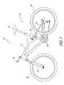
- FIG. 1is a perspective view of a bicycle having a preferred embodiment of a front wheel suspension fork
- FIG. 2is a perspective view of the suspension fork of FIG. 1 , which is illustrated as removed from the bicycle;
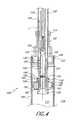
- FIG. 3is a cross-section of the suspension fork of FIG. 1 , thus illustrating the internal components of the fork;
- FIG. 4is an enlarged cross-section illustrating the rebound damping circuit of the suspension fork of FIG. 1 ;
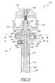
- FIG. 5is an enlarged cross-section of a rebound adjustment cap assembly of the suspension fork of FIG. 1 ;
- FIG. 6is a cross-section of the cap assembly taken along the line 6 - 6 in FIG. 5 ;
- FIG. 7is an enlarged cross-section of a base valve assembly of the suspension fork of FIG. 1 ;
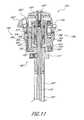
- FIG. 8is an enlarged cross-section of a rebound adjustment and lock-out cap assembly of a second embodiment of a suspension fork
- FIG. 9is a cross-section of the cap assembly of FIG. 8 , taken along the line 9 - 9 in FIG. 8 ;
- FIG. 10is a cross-section of a base valve assembly of the second embodiment.
- FIG. 11is a cross-section of a rebound adjustment, low speed compression adjustment and lock-out cap assembly of a third embodiment of a suspension fork;
- FIG. 12is a top view of a low-speed compression adjustment knob of the cap assembly of FIG. 11 ;
- FIG. 13is a cross-section of the low-speed compression adjustment knob of FIG. 12 , taken along the line 13 - 13 of FIG. 12 ;
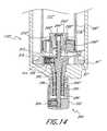
- FIG. 14is a cross-section of a blow-off adjustment base valve assembly of the third embodiment
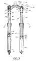
- FIG. 15is a cross-section of a coil-sprung embodiment having a coil spring in each leg for providing an expansion force on the fork;
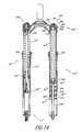
- FIG. 16is a cross-section of the coil-sprung fork of FIG. 15 in a shortened travel position.
- FIG. 1illustrates an off-road bicycle, or mountain bike 20 , including a frame 22 which is comprised of a main frame portion 24 and a swing arm portion 26 .
- the swing arm portion 26is pivotally attached to the main frame portion 24 .
- the bicycle 20includes front and rear wheels 28 , 30 connected to the main frame 24 .
- a seat 32is connected to the main frame 24 in order to support a rider of the bicycle 20 .
- the front wheel 28is supported by a preferred embodiment of a suspension fork 34 which, in turn, is secured to the main frame 24 by a handlebar assembly 36 .
- the rear wheel 30is connected to the swing arm portion 26 of the frame 22 .
- a rear shock 38is positioned between the swing arm 26 and the frame 22 to provide resistance to the pivoting motion of the swing arm 26 .
- the illustrated bicycle 20includes suspension members between the front and rear wheels 28 , 30 and the frame 22 which operate to substantially reduce wheel impact forces from being transmitted to the rider of the bicycle 20 .
- FIG. 2illustrates the suspension fork 34 detached from the bicycle 20 of FIG. 1 .
- the suspension fork 34includes right and left legs 40 , 42 , as referenced by a person in a riding position on the bicycle 20 .
- the right leg 40includes a right upper tube 44 telescopingly received in a right lower tube 46 .
- the left leg 42includes a left upper tube 48 telescopingly received in a left lower tube 50 .
- a crown 52connects the right upper tube 44 to the left upper tube 48 thereby connecting the right leg 40 to the left leg 42 of the suspension fork 34 .
- the crownsupports a steerer tube 54 , which passes through, and is rotatably supported by, the frame 22 of the bicycle 20 .
- the steerer tube 54provides a means for connection of the handlebar assembly 36 to the suspension fork 34 , as illustrated in FIG. 1 .
- Each of the right lower tube 46 and left lower tube 50includes a drop out 56 for connecting the front wheel 28 to the fork 34 .
- An arch 58connects the right lower tube 46 and the left lower tube 50 to provide strength and minimize twisting thereof.
- the right lower tube 46 , left lower tube 50 and the arch 58are formed as a unitary piece, however, the tubes 46 , 50 and arch 58 may be separate pieces and connected by a suitable fastening method.
- the suspension fork 34also includes a pair of rim brake bosses 60 to which a standard rim brake may be mounted.
- the fork 34may include a pair of disc brake bosses 62 to which a disc brake may be mounted.
- the suspension fork 34may include only one or the other of the rim brake bosses 60 and disc brake bosses 62 , depending on the type of brake system desired.
- FIG. 3is a cross-section view of the suspension fork 34 of FIG. 2 having the front portion cutaway to illustrate various internal components of the fork 34 .
- each of the upper tubes 44 , 48is capable of telescopic motion relative to its respective lower tube 46 , 50 .
- Each of the fork legs 40 , 42includes an upper bushing 64 and a lower bushing 66 positioned between the respective upper tubes 44 , 48 and the lower tubes 46 , 50 .
- the bushings 64 , 66inhibit wear of the upper tubes 44 , 48 and the lower tubes 46 , 50 by preventing direct contact between the tubes.
- the bushings 64 , 66are fixed to the respective lower tubes 46 , 50 and are made from a self-lubricating and wear resistant material, as is known in the art.
- the bushings 64 , 66may be similarly fixed to the upper tubes 44 , 48 .
- the bushings 64 , 66include grooves (not shown) which allow hydraulic fluid to pass between the bushings 64 , 66 and the upper fork tubes 44 , 48 .
- Each of the lower tubes 46 , 50have a closed lower end and an open upper end.
- Each of the upper tubes 44 , 48is received into a respective lower tube 46 , 50 through its open upper end.
- a sealing arrangementis provided on each leg 40 , 42 at the location where the upper tubes 44 , 48 enter the open end of the lower tubes 46 , 50 .
- the sealing arrangementcomprises a main seal 68 , preferably disposed above a foam ring 70 .
- the main seals 68are supported by the lower tubes 46 , 50 and are in sealing engagement with the upper tubes 44 , 48 to substantially prevent oil from exiting, or foreign material from entering, the fork legs 40 , 42 between the open end of the lower tubes 46 , 50 and the upper tubes 44 , 48 .
- the foam rings 70are supported by the lower tubes 46 , 50 and are in engagement with the upper tubes 44 , 48 to capture hydraulic fluid which passes upward between the upper bushings 64 and upper fork tubes 44 , 48 .
- the foam rings 70then distribute the hydraulic fluid evenly onto the upper tubes 44 , 48 which, in turn, lubricate the main seals 68 .
- Each of the fork legs 40 , 42includes a bottom-out bumper 72 disposed at the closed lower end of the lower tubes 46 , 50 .
- the bottom-out bumpers 72serve to prevent direct contact between the upper tubes 44 , 48 and the lower tubes 46 , 50 when the fork 34 is in a fully compressed position. Accordingly, the bottom-out bumpers 72 are preferably made of an energy absorbing material, such as an elastomer or rubber.
- the illustrated suspension fork 34includes both a suspension spring assembly 74 and a damper assembly 76 .
- the suspension spring assembly 74provides resistance to compression of the fork 34 and releases energy stored during compression to cause the fork 34 to extend, or rebound.
- the damper assembly 76provides a damping force which resists both compression and rebound motion, to slow the motion of the suspension fork 34 in either direction, as is known.
- the damper assembly 76is contained within the right leg 40 of the suspension fork 34
- the suspension spring assembly 74is contained within the left leg 42 .
- the suspension spring assembly 74comprises a spring cap assembly 80 which closes the upper end of the left upper tube 48 .
- a seal 81provides a preferably air and fluid-tight seal between the cap assembly 80 and the inner surface of the left upper tube 48 .
- a spring piston rod 84extends vertically upward from the closed lower end of the lower left fork tube 50 and supports a spring piston 86 .
- the piston 86includes a radial through-hole 85 which corresponds with a through-hole 87 in the piston rod 84 .
- a pin 89is press fit into the through-holes such that it engages the piston 86 on both sides of the piston rod 84 to secure the piston 86 thereto.
- the spring cap assembly 80is fixed for movement with the left upper tube 48 and the spring piston 86 is fixed for movement with the left lower tube 50 .
- the spring piston 86is in sealing engagement with the inner surface of the left upper tube 48 .
- the cap assembly 80 and piston 86define a positive air spring chamber 88 between them.
- a positive air valve 90allows communication with the positive air spring chamber 88 .
- a standard high pressure pumpmay be attached to the positive air valve 90 in order to pressurize the positive air spring chamber 88 .
- the positive air spring chamber 88acts as a suspension spring and exerts an extension force on the suspension fork assembly 34 .
- a cap 91is preferably threaded onto the valve 90 to provide protection from damage and keep foreign matter away from the valve 90 .
- a lower spring plate 92is held within a counter bore of the upper fork tube 48 by a snap ring 93 .
- An upper spring stop 95is fixed in an axial position on the spring piston rod 84 by a pin 97 , in a manner similar to the piston 86 , as described above.
- a negative spring chamber 94is defined between the lower spring plate 92 and upper spring stop 95 .
- An outer negative spring 96 and an inner negative spring 98are placed within the negative spring chamber 94 .
- the outer spring 96 and inner spring 98are coil-type springs arranged concentrically with each other and with the spring piston rod 84 .
- a pair of spring guides 99assist in keeping the springs 96 , 98 concentric with the piston rod 84 and from contacting the inner surface of upper tube 48 when compressed.
- the spring plate 92includes an central aperture 101 which provides clearance for the spring piston rod 84 to pass through.
- a small amount of lubricating fluidpreferably approximately 30 cc's of a suitable hydraulic damping fluid, is provided in the left fork leg 42 to lubricate the seal 68 , bushings 64 , 66 , negative springs 96 , 98 and spring guides 99 .
- the outer negative spring 96is of a greater length than the inner negative spring 98 .
- the spring rates of the outer and inner negative springs 96 , 98are selected such that the inner negative spring 98 is near its free-length when the suspension fork 34 is compressed by substantially only the weight of a rider of the bicycle 20 .
- the illustrated negative spring assemblycomprises a dual coil spring arrangement, a single negative spring may also be used.
- an air spring arrangement similar to the positive air spring chamber 88may also be used in place of the coil-type negative spring arrangement.
- the damper assembly 76is preferably housed within the right leg 40 of the suspension fork 34 .
- the damper assembly 76is preferably an open-bath, cartridge-type damper having a cartridge tube 100 fixed to the closed lower end of the right lower tube 46 and extending vertically upward.
- a damper shaft 102extends vertically downward from a damper cap assembly 104 and supports a rebound damping assembly 106 on its lower end.
- the rebound damping assembly 106is fixed for movement with the right upper tube 44 while the cartridge tube 100 is fixed for movement with the right lower tube 46 .
- the rebound damping assembly 106is positioned within the cartridge tube 100 and is in telescoping engagement with the inner surface of the cartridge tube 100 .
- a cartridge tube cap 108closes the upper end of the cartridge tube and is in sealing engagement with the damper shaft 102 .
- the cartridge tubedefines a substantially sealed internal chamber, which contains the rebound damping assembly 106 .
- the rebound damping assembly 106divides the interior of the cartridge tube 100 into a rebound chamber 110 above the rebound damping assembly 106 and a compression chamber 112 below the rebound damping assembly 106 .
- a reservoir 114is defined between the outer surface of the cartridge tube 100 and the inner surfaces of the right upper and lower tubes 44 , 46 .
- a base valve assembly 116allows selective communication between the compression chamber 112 and the reservoir 114 .
- the damper assembly 76also includes a rebound adjust rod 118 which extends vertically downward from the damper cap assembly 104 within the central passage of the damper shaft 102 .
- An upper compression passage 120is defined between the rebound adjust rod 118 and the inner surface of the damper shaft 102 .
- the upper compression passage 120allows communication between the compression chamber 112 and the damper cap assembly 104 , as will be described in detail below.
- FIG. 4is an enlarged cross-section of the rebound damping assembly 106 .
- a cartridge tube cap 108closes the cap end of the cartridge tube 100 .
- An outer seal 122creates a seal between the cartridge tube cap 108 and the cartridge tube 100 while an inner seal 124 creates a seal between the cartridge tube cap 108 and the damper shaft 102 . Accordingly, extension and retraction of the damper shaft 102 is permitted while maintaining the rebound chamber 110 in a substantially sealed condition.
- the seals referred to hereinmay comprise O-rings or other suitable seals known to those of skill in the art.
- a bushing 125is press fit into the cartridge tube cap 108 to prevent direct contact between the cap 108 and damper shaft 102 .
- a rebound piston support shaft 126is fixed within the lower opening of the damper shaft 102 and includes a seal 128 to prevent fluid from passing therebetween.
- the rebound piston support shaft 126 and the damper shaft 102are connected by a roll-crimping method.
- an annular recess 127is provided on the outer surface of the support shaft 126 .
- the damper shaft 102is substantially cylindrical and is positioned on the support shaft 126 such that it overlaps the annular recess 127 .
- a roll-crimping machinerotates the damper shaft 102 and support shaft 126 assembly while it mechanically deforms the damper shaft 102 material into the recess 127 (as illustrated in FIG.
- a tubular piston rod extension 130is fixed to the rebound adjust rod 118 by a threaded fastener 132 .
- a lower portion of the piston rod extension 130includes external threads which mate with internal threads of the rebound piston support shaft 126 .
- Rotation of the rebound adjust rod 118also rotates the piston rod extension 130 and results in axial movement of the piston rod extension 130 relative to the rebound piston support shaft 126 .
- Upward axial movement of the damper shaft 102uncovers a bleed port 134 , which extends radially through the rebound piston support shaft 126 , while downward axial movement of the damper shaft 102 covers the bleed port 134 .
- a rebound piston 136is fixed to the lowermost end of the rebound piston support shaft 126 by a hollow piston bolt 138 .
- the hollow passage of the piston bolt 138along with the hollow passage of the piston rod extension 130 define a lower compression passage 140 , which is in fluid communication with the compression chamber 112 .
- the upper end of the piston rod extension 130includes an aperture, or transfer port 142 , which allows fluid communication between the upper compression passage 120 and the lower compression passage 140 , as indicated by the arrow F in FIG. 4 .
- fluidis able to flow from the compression chamber 112 , through the lower compression passage 140 and upper compression passage 120 , to the damper cap assembly 104 .
- a lower end of the rebound piston support shaft 126includes a shoulder 144 which provides a support surface for a spacer 146 .
- the spacer 146engages the piston 136 to distance the piston 136 away from the shoulder 144 .
- a rebound piston seal 148creates a seal between the rebound piston 136 and the inner surface of the cartridge tube 100 , thereby defining the rebound chamber 110 above the piston 136 and the compression chamber 112 below the rebound piston 136 .
- the rebound piston 136includes a compression port 150 and a rebound port 152 extending substantially axially through the radially outer portion of the rebound piston 136 .
- a check valve assembly 156is arranged on the upper surface of the rebound piston 136 to selectively allow fluid communication from the compression chamber 112 to the rebound chamber 110 through the compression port 150 .
- the check valve 156includes a check plate 158 biased into an engagement with the upper surface of the piston 136 by a check spring 160 .
- the check plate 158is substantially annular in shape and capable of sliding axially with respect to the spacer 146 .
- the check spring 160is preferably a flat helical spring having a relatively low spring constant such that the spring 160 biases the check plate 158 into contact with the upper surface of the piston 136 to seal the compression port 150 during rebound motion, but easily compresses such that the check plate 158 moves away from the piston 136 to allow fluid flow through the compression port 150 in response to compression motion of the suspension fork 34 .
- a rebound shim stack 162is secured to the lower surface of the rebound piston 136 by the piston bolt 138 .
- the rebound shim stack 162may a single shim, or a stack comprised of multiple shims, which are substantially annular in shape and made from a flexible spring steel, as is known in the art.
- the rebound shim stack 162selectively allows fluid communication between the rebound chamber 110 and the compression chamber 112 through the rebound port 152 .
- the rebound shim stack 162is engaged with the lower surface of the piston 136 to prevent fluid from flowing through the rebound port 152 .
- the rebound shim stack 162acts as a diaphragm spring and flexes in response to a sufficient force of fluid pressure in the rebound chamber 110 , to allow fluid flow through the rebound port 152 and into the compression chamber 112 .
- a bleed port 163extends axially through the cartridge tube cap 108 between the seal 124 and the bushing 125 .
- the bleed port 163is sized such that air bubbles within the hydraulic fluid of the rebound chamber 110 can escape, without allowing an appreciable amount of fluid to pass therethrough.
- this constructionprevents a loss of incompressibility of the fluid within the rebound chamber 110 .
- FIG. 5is an enlarged cross-section of the upper control assembly, or damper cap assembly 104 .
- the suspension fork 34 of FIGS. 1-7utilizes a damper cap assembly 104 including a rebound adjustment control, as will be described in detail below.
- the rebound adjust rod 118 and damper shaft 102extend downward from the damper cap assembly 104 and define the upper compression passage 120 between them. As also described above, the damper cap assembly 104 closes the upper end of the right upper tube 44 .
- a cap seal 164creates a seal between the damper cap assembly 104 and the inner surface of the right upper tube 44 .
- the rebound adjust rod 118extends upward through the center of the damper cap assembly 104 and is fixed for rotation with a rebound adjustment knob 166 by a threaded fastener 168 .
- a rod seal 170creates a seal between the rebound adjust rod 118 and a central passage of the damper cap assembly 104 .
- the damper cap assembly 104is comprised primarily of a cap body 172 and a shaft support 174 .
- the damper shaft 102is roll-crimped to the shaft support 174 with a seal 176 preventing fluid flow therebetween.
- External threads on the upper portion of the shaft support 174mate with internal threads of an internal channel of the cap body 172 and secure a compression piston 178 and compression shim stack 180 therebetween.
- the shim stacks disclosed hereinare preferably comprised of one or more annular shims, preferably made from thin steel, as is known to those of skill in the art. Each individual shim acts as a diaphragm spring which possesses an inherent spring rate when deflected about its central axis. As is known, a plurality of shims may be used to achieve a desired spring rate.
- the shims making up a single shim stackmay vary in diameter, preferably with the largest diameter shim being located immediately adjacent the surface defining the ports through which the shim stack is controlling flow. For example, if a shim stack utilizing multiple diameter shims is used with the above-described damper cap assembly 104 , preferably the largest diameter shim is located immediately adjacent lower surface of the compression piston 178 .
- the compression piston 178is axially spaced from the cap body 172 by a shoulder 182 to create a compression chamber 184 between the upper surface of the piston 178 and the lower surface of the cap body 172 .
- the shoulder 182is integral with the cap body 172 .
- a sealis created between the outer radial surface of the compression piston 178 and the cap body 172 by a piston seal 186 .
- the shaft support 174includes radially extending ports 188 which allow fluid communication between the upper compression passage 120 and an annular transfer chamber 189 defined between the shaft support 174 and the shoulder 182 .
- Radial passages in the shoulder 182allow fluid communication between the transfer chamber 189 and the compression chamber 184 .
- the radial ports 188 and radial passages 190cooperate with the transfer chamber 189 to allow fluid communication between the upper compression passage 120 and the compression chamber 184 .
- the transfer chamber 189allows fluid communication between the radial ports 188 and radial passages 190 despite their relative angular positions.
- the compression piston 178includes a low speed compression port 192 and a plurality of mid-speed compression ports 194 passing axially therethrough. As illustrated in FIG. 6 , the mid-speed compression ports 194 are disposed at a first radial distance D 1 from a center axis A of the piston 178 while the low-speed compression ports are located a second radial distance D 2 from the axis A. Preferably, the distance D 1 is less than the distance D 2 .
- this arrangementprovides separate low and mid-speed damping circuits, while remaining compact and without adding undesired weight.
- One or more high-speed compression ports 195may be provided and be of a smaller diameter or located a smaller radial distance D 3 from the axis A, or a combination thereof, than the mid-speed compression ports 194 .
- Such a constructionwould allow the high-speed compression ports to be relatively inactive at low and mid-speed shaft motion, while providing the primary damping force at high-speed shaft motion.
- a plurality of port diameters and radial locations from the axis Amay be used to achieve desired damping forces at specific shaft speeds.
- a combination of portsmay be used to provide varying damping forces over a range of shaft speeds.
- the damper cap assembly 104also includes a ball detent assembly 196 .
- the ball detent assembly 196comprises a spring 198 placed between a set screw 200 and a ball bearing 202 to bias the ball bearing 202 into engagement with one of a plurality of recesses, or detents 204 , formed on the rebound adjust rod 118 .
- the spring rate of the spring 198is selected such that the biasing force of the spring 198 may be easily overcome so that the rebound adjustment knob 166 may be turned by hand, while also providing positive feedback as to the relative position of the rebound adjust rod 118 .
- four (4) detents 204are equally spaced around the circumference of the rebound adjust rod 118 .
- the rebound adjust rod 118is desirably capable of rotating approximately three (3) revolutions between its upper position and its lower position. Accordingly, twelve (12) distinct rebound damping positions are defined by the rebound adjust rod 118 and the ball detent assembly 196 .
- FIG. 7is an enlarged cross-section of the lower control assembly, or base valve assembly 116 .
- the base valve assembly 116allows selective communication between the reservoir 114 and the compression chamber 112 .
- the base valve assembly 116generally comprises a valve body 206 , a shim bolt 208 and a check shim 210 .
- a lower portion of the shim bolt 208includes external threads which mate with internal threads of the base valve body 206 .
- the shim bolt 208includes a shaft portion 212 which centers the substantially annular check shim 210 with respect thereto.
- the shim bolt 208also includes a shoulder portion 214 of larger diameter than the shaft portion 212 such that the check shim 210 is capable of limited axial movement between the upper surface of the base valve body 206 and a shoulder portion 214 of the shim bolt 208 .
- a check spring 213biases the check shim 210 into engagement with the top surface of the base valve body 206 .
- the spring 213is a conical coil spring having a low spring rate and small wire diameter so that it allows the check shim 210 to move easily away from the top surface of the base valve body 206 .
- the small end of the spring 213engages the base valve body 206 while the large end engages the check shim 210 .
- a low axial travel shim without a springmay be used.
- the radial outer portion of base valve body 206also includes a plurality of refill ports 216 which pass axially therethrough.
- the check spring 213keeps the check shim 210 engaged with the top surface of the base valve body 206 , thus closing off the axial refill ports 216 and effectively preventing the flow of fluid therethrough.
- the check shim 210moves away from the base valve body 206 , against the small biasing force of the spring 213 , to allow fluid flow from the reservoir 114 to the compression chamber 112 , through the refill ports 216 .
- the configuration and spring rate of the check spring 213allows the check shim 210 to move easily away from the top surface of the base valve body 206 in order to prevent flow restriction which could result in cavitation, but also returns the check shim 210 quickly into engagement with the base valve body on compression movement of the fork 34 .
- the suspension fork assembly 34 described in relation to FIGS. 1-7is capable of both compression, where the upper tubes 44 , 48 and the lower tubes 46 , 50 move closer together relative to each other and rebound, wherein the upper tubes 44 , 48 and the lower tubes 46 , 50 move farther apart in relation to each other.
- a fully compressed positionis defined wherein the suspension fork 34 is compressed such that the lower-most surfaces of the upper tubes 44 , 48 come to rest against the pair of bottom-out bumpers 72 .
- a fully extended positionis defined when the upper tubes 44 , 48 are retracted from the lower tubes 46 , 50 such that the outer and inner negative springs 96 , 98 are fully compressed between the negative spring chamber seal 92 and the spring piston 86 .
- a ride height of the suspension fork assembly 34is defined as the relative position between the upper tubes 44 , 48 and the lower tubes 46 , 50 when the suspension fork 34 is bearing the weight of a rider of the bicycle 20 , with substantially no other external forces being present.
- the ride heightis preferably such that the inner negative spring 98 is substantially near its free length, or its uncompressed length, when no other external force is exerted on the spring.
- the ride heightcan be adjusted to suit riders of different weights by tuning the positive air spring chamber 88 and/or the outer and inner negative springs 96 , 98 . Air can be added or removed from the positive air spring chamber 88 to adjust the pressure therein.
- the free length and/or spring rate of the outer and inner negative springs 96 , 98may also be selected to achieve the desired ride height.
- the air within the positive air spring chamber 88functions as an air spring to progressively resist compression of the upper tubes 44 , 48 into the lower tubes 46 , 50 .
- the outer and inner negative springs 96 , 98exert a compressive force on the suspension fork 34 and thereby assist the initial compressive motion between the upper tubes 44 , 48 and the lower tubes 46 , 50 .
- the negative springs 96 , 98help to overcome any static friction present in the suspension fork 34 , due to the bushings and various seals, in order to allow initial compression with a minimal force input.
- the above-described damper assembly 76includes various flow paths which provide damping to the motion of the suspension fork 34 in both a compression and a rebound direction.
- the various flow pathscan be generally categorized into compression circuits and rebound circuits. Of course, some passages may be utilized for both compression and rebound fluid flow.
- the damper assembly 76includes a sufficient volume of a suitable damping fluid such that at least the entire cartridge tube 100 , upper and lower compression passages 120 , 140 and damper cap assembly 104 may be filled, and enough damping fluid remains in the reservoir 114 to cover the refill ports 216 of the base valve assembly 116 .
- the rebound piston 136moves downward in relation to the cartridge tube 100 and, as a result, the fluid pressure within the compression chamber 112 increases.
- hydraulic fluid contained thereinpasses through the check valve assembly 156 of the rebound piston 136 to the rebound chamber 110 .
- the check spring 160that biases the check plate 158 against the top surface of the rebound piston 136 desirably has a low spring rate and therefore offers little resistance to fluid flow through the compression ports 150 .
- fluid flow from the compression chamber 112 to the rebound chamber 110 through the check valve 156serves primarily to fill the rebound chamber 110 and, desirably, provides little damping force.
- fluidflows in an upward direction from the compression chamber 112 into the lower compression passage 140 .
- a portion of the fluidflows from the lower compression passage 140 through the bleed port 134 and into the rebound chamber 110 .
- the flow of fluid through the bleed port 134serves primarily to fill the rebound chamber 110 and, preferably, does not provide a substantial damping force.
- the remainder of the fluidcontinues to flow upward in the lower compression passage 140 and into the upper compression passage 120 through the transfer port 142 .
- the flow of fluidcontinues to travel upward through the upper compression passage 120 and into the damper cap assembly 104 .
- the flow of fluidthen travels through both the radial port 188 of the shaft support 174 and the radial passage 190 of the piston shoulder 182 and into the compression chamber 184 , thus increasing the fluid pressure therein.
- the compression shim stack 180is deflected from the lower surface of the compression piston 178 at lower fluid pressures than is necessary to deflect the shim stack 180 to open the mid-speed compression ports 194 .
- the primary damping forceis provided by the flow through the low speed compression port 192 which is resisted by the compression shim stack 180 at low fluid pressures which correspond with low speed compressive motion.
- hydraulic fluid within the reservoir 114is also able to move throughout the reservoir 114 and, advantageously, provides lubrication for the bushings 64 , 66 and various seals within the damper assembly 76 .
- the rebound piston 136moves in an upward direction with respect to the cartridge tube 100 , thereby increasing the pressure in the rebound chamber 110 .
- fluidflows through the bleed port 134 and downward through the lower compression passage 140 and then to the compression chamber 112 .
- the rebound adjustment knob 166may be rotated to in turn rotate the rebound adjust rod 118 and cause the piston rod extension 130 to increase or decrease the exposed portion of the bleed port 134 . In this manner, the damping force provided by the restricted flow of fluid through the bleed port 134 may be adjusted.
- the rebound adjustment knob 166is disposed on the damper cap assembly 104 , it may be easily manually adjusted by the rider of the bicycle 20 , even while riding. In addition, no tools are necessary to change the damping rate and such adjustment may be made externally, without requiring disassembly of the suspension fork 34 .
- fluidflows through the rebound port 152 and, if the fluid pressure is greater than a predetermined threshold, deflects the rebound shim stack 162 away from the bottom surface of the rebound piston 136 to allow fluid to flow from the rebound chamber 110 to the compression chamber 112 .
- Rebound damping forceis provided by the rebound shim stack 162 against the flow of fluid through the rebound port 152 .
- the suspension fork 34additionally includes a refill feature which operates to refill the compression chamber 112 during rebound motion.
- the compression shim stack 180 within the damper cap assembly 104creates a substantially air-tight seal with the lower surface of the compression piston 178 .
- the low pressure condition in the compression chamber 112is not able to suction fluid from within the upper compression passage 120 .
- Thisensures that the upper compression passage 120 and damper cap assembly 104 remain filled with fluid.
- the upper compression passage 120 and compression chamber 184do not have to be refilled upon subsequent compression motion of the suspension fork 34 before producing a damping force.
- the seal between the compression shim stack 180 and the compression piston 178serves to draw fluid from the reservoir 114 and into the compression chamber 112 through the base valve assembly 116 .
- FIGS. 8-10illustrate relevant portions of an alternative embodiment of a suspension fork, generally indicated by the reference character 34 ′.
- Suspension fork 34 ′in addition to having an adjustable rebound damping circuit, features a high-speed compression circuit (or blow-off) and a low/mid-speed compression lock-out.
- suspension fork 34 ′is similar in both construction and function to the suspension fork 34 of FIGS. 1-7 . Accordingly, like components will be indicated with like reference numerals, except that a (′) will be added.
- the central passage of the cap body 172 ′is increased in diameter to accommodate a lock-out cylinder 218 positioned between the cap body 172 ′ and the rebound adjust rod 118 ′.
- a seal 220provides a substantially fluid and air-tight seal between the lock-out cylinder 218 and the inner surface of the central passage of the cap body 172 ′.
- cap seal 164 ′provides a seal between the rebound adjust rod 118 ′ and the inner surface of a central passage of the lock-out cylinder 218 , rather than between the rebound adjust rod 118 and the cap body 172 , as in the previous embodiment.
- the lock-out cylinder 218includes a externally threaded portion 222 which mates with the internal threads of the cap body 172 ′. Accordingly, rotation of the lock-out cylinder 218 results in corresponding axial movement of the lock-out cylinder 218 with respect to the cap body 172 ′.
- the mating threads of the cap body 172 ′ and the lock-out cylinder 218are 10 mm diameter by 1 mm pitch, double-start threads. With such a construction, relatively large axial motion is achieved with a relatively small degree of rotation of the lock-out cylinder 218 .
- a blocking sleeve 224extends in a downward direction from, and is preferably unitary with, the lock-out cylinder 218 .
- the blocking sleeve 224is configured to selectively allow fluid to pass, or substantially prevent fluid from passing, from the upper compression passage 120 ′ to the compression chamber 184 ′.
- the lower end of the blocking sleeve 224is configured to mate with a blocking sleeve seat 226 of the shaft support 174 ′.
- An upper-most, or “open”, position of the lock-out cylinder 218is defined when the blocking sleeve 224 is retracted such that the radial ports 188 ′ of the shaft support 174 ′ and the radial passages 190 ′ of the piston shoulder 182 ′ are substantially fully open, thereby allowing fluid to flow from the upper compression passage 120 ′ to the compression chamber 184 ′ (reference FIG. 6 ).
- a lower-most, or “closed”, position of the lock-out cylinder 218is defined when the blocking sleeve 224 is advanced such that the radial ports 188 ′ and radial passages 190 ′ are substantially fully closed, thereby substantially prohibiting the flow of fluid from the upper compression passage 120 ′ to the compression chamber 184 ′.
- the lock-out cylinder 218moves between its open and closed positions with less than one revolution, preferably, with less than one-half revolution and, most preferably, with less than one-third revolution. The lock-out can be actuated more quickly and easily by the rider when the amount of rotation between the open and closed position is relatively small.
- a lock-out knob 228is engaged with the upper portion of the lock-out cylinder 218 and is supported for rotation on the cap body 172 ′ by a ball bearing arrangement 230 .
- a plurality of ball bearings 232travel within an annular recess 234 ( FIG. 8 ) defined by the cap body 172 ′ and are secured in recess 234 by a plurality of set screws 236 .
- the set screws 236each have a substantially cone-shaped lower end 238 which engages one of the plurality of ball bearings 232 .
- the lock-out knob 228is secured in an axial position with respect to the cap body 172 ′ while being capable of rotation with respect thereto.
- the lock-out cylinder 218engages the upper portion of the lock-out knob 228 .
- the mating portions of the lock-out cylinder 218 and the lock-out knob 228each have a hex-shaped cross-section thereby fixing the lock-out cylinder 218 for rotation with the lock-out knob 228 .
- the lock-out cylinder 218is able to move axially with respect to the lock-out knob 228 by sliding motion between the hex-shaped cross-sections.
- the lock-out knob 228also includes a lever portion 240 which provides a convenient surface for a rider of the bicycle 20 ( FIG. 1 ) to grasp in order to rotate the lock-out knob 228 .
- the lever portion 240also provides a leverage advantage to increase the ease with which the lock-out knob 228 may be rotated.
- a preferred base valve assembly 116 ′for use in conjunction with the damper cap assembly 104 ′ described immediately above.
- the present base valve assembly 116 ′includes a blow-off circuit 242 .
- the blow-off circuit 242selectively allows fluid flow from the compression chamber 112 ′ to the reservoir 114 ′ at high compressive fluid pressures or shaft speeds.
- the blow-off circuit 242remains closed at compressive fluid pressures below the threshold necessary to open the low and mid-speed compression circuits of the suspension fork 34 ′.
- the blow-off compression circuit 242generally comprises a valve opening 244 , a blow-off piston 246 and a blow-off spring 248 .
- the valve opening 244is defined by a central passage of the shim bolt 208 ′ and includes a blow-off piston seat 250 .
- the blow-off spring 248is supported on a spring support shaft 252 and biases the blow-off piston into engagement with the blow-off piston seat 250 to substantially prevent fluid from passing through the valve opening 244 at fluid pressures below a predetermined threshold. This threshold is determined by a combination of the spring rate of the blow-off spring 248 , the preload on the spring 248 and the area of the blow-off piston 246 that is subject to fluid pressure from the compression chamber 112 .
- valve 242operates to allow fluid flow from the compression chamber 112 ′ to the reservoir 114 ′.
- thisprevents damage to the various seals of the suspension fork 34 ′ and prevents the entire force of the bump from being transferred to the rider.
- the placement of the lock-out knob 228 on the damper cap assembly 104 ′allows easy access to the rider of the bicycle 20 ( FIG. 1 ), even while riding. This is advantageous because a wide variety of terrain may be encountered in a single ride such that “on-the-fly” (while riding) actuation of the lock-out knob 228 is highly desirable. Furthermore, because the low, mid and high-speed compression circuits are locked-out within the damper cap assembly 104 ′, the lock-out cylinder 218 remains mechanically simple and compact, thereby decreasing the likelihood of failure, saving weight and reducing the cost of manufacture in comparison to lock-out assemblies located in the middle or lower region of the fork leg, which often require complex actuation mechanisms.
- FIGS. 11-14illustrate relevant portions of another embodiment of a suspension fork, generally indicated by the reference character 34 ′′.
- Suspension fork 34 ′′in addition to having an adjustable rebound damping circuit, a blow-off circuit and a low/mid-speed compression lock-out of the previously described suspension forks 34 , 34 ′, respectively, includes adjustable low-speed compression damping and blow-off pressure.
- suspension fork 34 ′′is similar in both construction and function to the suspension fork 34 and 34 ′ of FIGS. 1-7 and 8 - 10 , respectively. Accordingly, like components will be indicated with like reference numerals, except that a (′′) will be added.
- the damper cap assembly 104 ′′includes a low-speed compression damping adjustment assembly 256 , which generally comprises a low-speed compression adjustment knob 258 , an adjustment needle 260 and a needle spring 262 .
- the adjustment needle 260is supported for axial movement within a needle aperture 264 , which extends axially through the cap body 172 ′′, and above the low speed compression port 192 ′′.
- a seal 266provides a seal between the adjustment needle 260 and the cap body 172 ′′.
- the adjustment needle 260includes an annular flange, or needle stop 268 , which interferes with the cap body 172 ′′ to define the upper most position of the adjustment needle 260 with respect to the compression piston 178 ′′. In its uppermost position, a lower tapered end 270 of the adjustment needle 260 preferably does not substantially interfere with fluid flow through the low-speed compression port 192 ′′.
- the needle stop 268also functions as an engagement surface for the needle spring 262 , which is positioned between the needle stop 268 and the upper surface of the compression piston 178 ′′ to bias the adjustment needle 260 into its uppermost position.
- a lowermost position of the adjustment needle 260is defined when the needle 260 is force in a downward direction, overcoming the biasing force of the needle spring 262 , by the low-speed compression knob 258 , as will be described below.
- the tapered end 270 of the needle 260is positioned within the low-speed compression port 192 ′′ to substantially inhibit fluid flow therethrough. In this manner, the damping force at low shaft speeds is increased.
- the needle 260may be configured to seat with the low-speed compression port 192 ′′ in its lowermost position, thereby effectively preventing fluid flow through the low-speed compression port 192 ′′.
- the low speed compression adjustment knob 258is positioned between the lock-out knob 228 ′′ and the cap body 172 ′′ for rotation with respect to the cap body 172 ′′.
- the adjustment knob 258engages the adjustment needle 260 to move the needle 260 between its uppermost and lowermost positions.
- the adjustment knob 258includes an arcuate needle adjustment channel 272 ( FIGS. 12 and 13 ), which extends radially about a central axis of the adjustment knob 258 for a specified angle .theta. Desirably, the angle is between 90 and 180.degree. Preferably, the angle is approximately 144.degree. This range provides a desirable amount of adjustment while keeping the rotation of the adjustment knob 258 small enough to be comfortable to actuate while riding.
- the upper surface of the channel 272defines a needle ramp surface 274 , which is inclined relative to the upper surface of the compression piston 178 ′′.
- An engagement surface 276( FIG. 11 ), defined by the upper portion of the adjustment needle 260 , engages the ramp surface 274 of the adjustment knob 258 such that rotation of the adjustment knob 258 moves the adjustment needle 260 substantially between its uppermost and lowermost positions.
- Each end of the channel 272defines a stop surface 278 , which interferes with the upper end of the adjustment needle 260 to define the limits of the range of motion for rotation of the adjustment knob 258 .
- a vertical distance V( FIG. 13 ) between the shallowest end of the ramp surface 274 and the deepest end of the ramp surface 274 is approximately 0.10 inches. Accordingly, the height of the tapered end 270 of the adjustment needle 260 varies by 0.10 inches with respect to the upper surface of the compression piston 178 ′′ when the adjustment knob 258 is rotated through its full range of motion.
- the adjustment knob 258additionally includes a ball detent mechanism 280 , which is similar in both structure and operation to the detent mechanism 196 ′′ associated with the rebound adjust rod 118 ′′.
- the ball detent mechanism 280includes a ball bearing 282 which is biased into engagement with one of a plurality of detents 284 , defined by the adjustment knob 258 , by a spring 286 . Both the ball bearing 282 and the spring 286 are contained within a spring pocket 288 , which is defined by the cap body 172 ′′.
- nine (9) detentsare provided throughout the range of motion of the adjustment knob 258 , thereby providing nine (9) positive reference positions, which define individual settings of the low-speed compression adjustment assembly 256 .
- the adjustment knob 258also includes an annular flange which defines a finger grip portion 290 .
- the outer peripheral surface of the finger grip portion 290includes a plurality of recesses 292 , which preferably extend entirely around the finger grip portion 290 .
- the recesses 292provide an interrupted surface, which permits the adjustment knob 258 to be easily rotated, even in muddy or wet conditions.
- the construction of the damper cap assembly 104 ′′allows the level of low-speed compression damping to be adjusted externally, without necessitating disassembly of the suspension fork 34 ′′.
- the level of low-speed compression dampingmay be adjusted on-the-fly. This provides an important advantage if the terrain conditions change over the course of a ride, or race, or if it turns out that the initial setting was less than desirable.
- a preferred base valve assembly 116 ′′is illustrated for use in conjunction with the damper cap assembly 104 ′′ described immediately above.
- the present base valve assembly 116 ′′ of FIG. 14includes a blow-off adjustment assembly 294 .
- the blow-off spring support shaft 262 ′′extends through an open end 296 of the base valve body 206 ′′.
- the support shaft 262 ′′includes an externally threaded portion 298 , which mates with internal threads 300 of the base valve body 206 ′′.
- rotation of the blow-off spring support shaft 262 ′′is converted to axial movement of the support shaft 262 ′′ in relation to the base valve body 206 ′′.
- Axial movement of the support shaft 262 ′′varies the relaxed length of the blow-off spring 248 ′′, and thereby varies the preload on the spring 248 ′′.
- the preload of the blow-off spring 248 ′′influences the threshold fluid pressure within the compression chamber 112 ′′ which is necessary to open the blow-off valve 242 ′′. More preload raises the threshold pressure, while less preload decreases the threshold pressure.
- a blow-off adjustment knob 302is secured to the lower, exposed end of the support shaft 262 ′′ by a set screw 304 .
- the adjustment knob 302allows the support shaft to be rotated easily by hand.
- a seal 305creates a seal between the support shaft 262 ′′ and the base valve body 206 ′′ to substantially inhibit fluid from passing therebetween.
- the blow-off adjustment assembly 294also includes a ball detent assembly 306 , which is similar to the ball detent assemblies described above.
- the ball detent assembly 306includes a ball bearing 308 biased into engagement with a detent 310 defined by the support shaft 262 ′′ by a spring 312 .
- the ball bearing 308 and spring 312are secured within a cavity 314 by a set screw 316 .
- four (4) detents 310are provided and the support shaft 262 ′′ is capable of making three (3) revolutions, thereby defining twelve (12) blow-off damping adjustment positions.
- the suspension fork 34 ′′ described immediately aboveprovides a wide range of both compression and rebound adjustment.
- Low-speed compression, rebound damping, blow-off pressure, as well as a compression lock-out featuremay all be accessed, and adjusted, externally and without the use of any tools.
- the low-speed compression and rebound damping circuits, and lock-out, controlsare conveniently located on the upper portion of the suspension fork 34 ′′.
- “on-the-fly” access to the above-mentioned controlsis provided, thereby permitting damping adjustment and actuation of the lock-out feature while the bicycle 20 ( FIG. 1 ) is being ridden.
- Such a constructionprovides a distinct advantage by allowing initial damping settings to be adjusted, and the lock-out feature actuated, during the course of a ride or race.
- FIGS. 15 and 16illustrate a coil-sprung embodiment of the suspension fork, indicated generally by the reference character 34 ′′′.
- Suspension fork 34 ′′is similar in both construction and function to the previously described suspension forks 34 , 34 ′ and 34 ′′. Accordingly, like components will be indicated with like reference numerals, except that a (′′′) will be added.
- the coil-sprung fork 34 ′′′utilizes a pair of positive coil springs to provide an expansion force on the fork 34 ′′′.
- a first spring 320is located in the right fork leg 40 ′′′, along with the damper assembly 76 ′′′, while a second spring 322 is located in the left leg 42 ′′′, in place of the air spring arrangement of the previous embodiments.
- a pair of coil springsmay be advantageous. With a coil spring 320 , 322 located in each of the fork legs 40 ′′′, 42 ′′′, respectively, the expansion force on the fork 34 ′′′ is more equally balanced between the fork legs 40 ′′′, 42 ′′′. This enhances the coaxial telescopic motion of the upper legs 44 ′′′, 48 ′′′ relative to the lower legs 46 ′′′, 50 ′′′ during compression and rebound for smooth motion with reduced binding.
- the first spring 320is positioned in the right leg 40 ′′′ between the damper cap assembly 104 ′′′ and the cartridge tube cap 108 ′′′.
- a pair of spacersincluding a first spacer 324 and a second spacer 326 , are interposed between the damper cap assembly 104 ′′′ and the first spring 320 .
- the spacers 324 , 326are preferably substantially C-shaped so that they may be easily removed from the damper shaft 102 ′′′ in a radial direction. Desirably, the spacers 324 , 326 are configured to engage the damper shaft 102 ′′′ in a snap fit arrangement.
- a spring guide 328is positioned between the spring 320 and the spacer immediately adjacent the spring 320 (spacer 326 in the illustrated embodiment) to assist in keeping the spring 320 concentric with the damper shaft 102 ′′′.
- the cartridge tube cap 108 ′′′functions as a spring guide for the lower end of the first spring 320 .
- a separate spring guide membermay also be provided.
- the second spring 322is positioned in the left leg 42 ′′′ between the spring cap assembly 80 ′′′ and the upper spring stop 95 ′′′.
- a first spacer 324 and a second spacer 326are positioned between the spring cap assembly 80 ′′′ and the spring 322 .
- the first and second spacers 324 , 326are substantially identical to the spacers described above in relation to the first spring 320 .
- a preload adjuster assembly 330is desirably provided to allow adjustment of the preload on the second spring 322 .
- the preload adjuster assembly 330generally comprises an adjuster cap 332 , an adjuster shaft 334 , a barrel 336 and an adjuster knob 338 .
- the cap 332is sealingly engaged with upper open end of the upper tube 48 ′′′.
- the cap 332includes a central aperture which allows the adjuster shaft 334 to pass through, preferably in a sealed arrangement.
- the adjuster knob 338is fixed to the adjuster shaft 334 by fastener 340 such that rotation of the adjuster knob 338 results in rotation of the adjuster shaft 334 .
- a ball detent assembly 341substantially similar to those described above, may be provided between the cap 332 and the adjuster knob 338 to define a plurality of preload adjustment positions.
- the barrel 336is threadably engaged with the adjuster shaft 334 and engages the upper most spacer 326 .
- the barrel 336includes a ball pocket for holding a ball bearing 342 , which rides within an axial groove 344 defined by the adjuster cap 332 . This arrangement prevents the barrel 336 from rotating relative to the adjuster cap 332 . Accordingly, rotation of the adjuster shaft 334 , via the adjuster knob 338 , results in translation of the barrel 336 relative to the adjuster cap 332 . A change in the axial position of the barrel 336 alters the preload force on the spring 322 .
- the upper spring stop 95 ′′′is roll-crimped to a plunger rod 346 which extends upward from the closed end of the lower fork tube 50 ′′′.
- the upper stop 95 ′′′includes an o-ring 348 which serves as a spring guide for the lower end of the spring 322 .
- the o-ring 348is preferred because it's compressibility allows a single size of o-ring to accommodate a number of different spring inner diameters. The inner diameter of a spring may vary with different spring rates, therefore, the o-ring 348 allows a number of springs 322 having varying spring rates to be used with the fork 34 ′′′.
- a negative spring chamber 94 ′′′is defined between the upper spring stop 95 ′′′ and the lower spring stop 92 ′′′.
- a single negative spring 96 ′′′is provided, rather than the dual negative coil spring arrangement of previous embodiments.
- the fork assembly 34 ′′′ of FIGS. 15 and 16is capable of being adjusted for varying amounts of travel, or total distance between it's fully compressed and fully extended positions.
- the fork 34 ′′′has been configured to have less travel than the fork 34 ′′′ as configured in FIG. 15 .
- the spacers 324 , 326 of the left leg 42 ′′′were moved from their position between the upper end of the spring 322 and the spring cap assembly 80 ′′′ to a position below the plunger rod 346 .
- the upper spring guide 99 ′′′is slid downward on the plunger rod 346 and the spacers 324 , 326 are positioned between the upper spring guide 99 ′′′ and the upper spring stop 95 ′′′.
- the spacers 324 , 326( FIG. 15 ) are removed from the right fork leg 40 .
- the first spacer 324is approximately 20 mm in length and the second spacer 326 is approximately 25 mm in length.
- the travel of the fork 34 ′′′ as configured in FIG. 15is approximately 125 mm. As configured in FIG. 16 , the travel is reduced to 80 mm.
- only one of the spacers 324 , 326may be positioned below the upper spring stop 95 ′′′ while the other spacer remains positioned above the spring 324 . With this configuration, the fork travel would be shortened by the length of the spacer positioned below the upper spring stop 95 ′′′, either 20 mm or 25 mm.
- the corresponding spacer 324 , 326would be removed from the right fork leg 40 , to maintain the desired preload on the spring 320 , as described above. Additionally, varying spacer configurations could be used. For example, the spacers 324 , 326 could be replaced by a single spacer. Also, spacers of other lengths may be used, as can readily be determined by one of skill in the art.
- damper assembly and spring assemblymay be contained within a single leg of the fork, with the other leg being substantially empty.
- the forkcould configured to have a single fork leg, with both the damper and suspension spring elements being arranged within the single leg.
- the forkmay be configured for use with other vehicles, such as a road bicycle or motorcycle, for example. Accordingly, the scope of the invention is intended to be defined only by the appended claims.
Landscapes
- Engineering & Computer Science (AREA)
- General Engineering & Computer Science (AREA)
- Mechanical Engineering (AREA)
- Fluid-Damping Devices (AREA)
- Axle Suspensions And Sidecars For Cycles (AREA)
Abstract
Description
Claims (6)
Priority Applications (5)
| Application Number | Priority Date | Filing Date | Title |
|---|---|---|---|
| US13/250,886US8459418B2 (en) | 2001-07-02 | 2011-09-30 | Bicycle fork having lock-out, blow-off, and adjustable blow-off threshold |
| US13/898,396US8727366B2 (en) | 2001-07-02 | 2013-05-20 | Bicycle fork having lock-out, blow-off, and adjustable blow-off threshold |
| US14/256,621US9004516B2 (en) | 2001-07-02 | 2014-04-18 | Bicycle fork having lock-out, blow-off, and adjustable blow-off threshold |
| US14/640,941US9586645B2 (en) | 2001-07-02 | 2015-03-06 | Bicycle fork having lock-out, blow-off, and adjustable blow-off threshold |
| US15/418,515US10337584B2 (en) | 2001-07-02 | 2017-01-27 | Bicycle fork having lock-out, blow-off, and adjustable blow-off threshold |
Applications Claiming Priority (5)
| Application Number | Priority Date | Filing Date | Title |
|---|---|---|---|
| US09/897,706US6592136B2 (en) | 2001-07-02 | 2001-07-02 | Bicycle fork cartridge assembly |
| US10/620,323US7163222B2 (en) | 2001-07-02 | 2003-07-15 | Bicycle fork having lock-out, blow-off, and adjustable blow-off threshold |
| US11/532,524US7708296B2 (en) | 2001-07-02 | 2006-09-16 | Bicycle fork having lock-out, blow-off, and adjustable blow-off threshold |
| US12/732,245US8033368B2 (en) | 2001-07-02 | 2010-03-26 | Bicycle fork having lock-out, blow-off, and adjustable blow-off threshold |
| US13/250,886US8459418B2 (en) | 2001-07-02 | 2011-09-30 | Bicycle fork having lock-out, blow-off, and adjustable blow-off threshold |
Related Parent Applications (1)
| Application Number | Title | Priority Date | Filing Date |
|---|---|---|---|
| US12/732,245ContinuationUS8033368B2 (en) | 2001-07-02 | 2010-03-26 | Bicycle fork having lock-out, blow-off, and adjustable blow-off threshold |
Related Child Applications (1)
| Application Number | Title | Priority Date | Filing Date |
|---|---|---|---|
| US13/898,396ContinuationUS8727366B2 (en) | 2001-07-02 | 2013-05-20 | Bicycle fork having lock-out, blow-off, and adjustable blow-off threshold |
Publications (2)
| Publication Number | Publication Date |
|---|---|
| US20120018265A1 US20120018265A1 (en) | 2012-01-26 |
| US8459418B2true US8459418B2 (en) | 2013-06-11 |
Family
ID=25408291
Family Applications (9)
| Application Number | Title | Priority Date | Filing Date |
|---|---|---|---|
| US09/897,706Expired - LifetimeUS6592136B2 (en) | 2001-07-02 | 2001-07-02 | Bicycle fork cartridge assembly |
| US10/620,323Expired - LifetimeUS7163222B2 (en) | 2001-07-02 | 2003-07-15 | Bicycle fork having lock-out, blow-off, and adjustable blow-off threshold |
| US11/532,524Expired - LifetimeUS7708296B2 (en) | 2001-07-02 | 2006-09-16 | Bicycle fork having lock-out, blow-off, and adjustable blow-off threshold |
| US12/732,245Expired - Fee RelatedUS8033368B2 (en) | 2001-07-02 | 2010-03-26 | Bicycle fork having lock-out, blow-off, and adjustable blow-off threshold |
| US13/250,886Expired - LifetimeUS8459418B2 (en) | 2001-07-02 | 2011-09-30 | Bicycle fork having lock-out, blow-off, and adjustable blow-off threshold |
| US13/898,396Expired - Fee RelatedUS8727366B2 (en) | 2001-07-02 | 2013-05-20 | Bicycle fork having lock-out, blow-off, and adjustable blow-off threshold |
| US14/256,621Expired - Fee RelatedUS9004516B2 (en) | 2001-07-02 | 2014-04-18 | Bicycle fork having lock-out, blow-off, and adjustable blow-off threshold |
| US14/640,941Expired - Fee RelatedUS9586645B2 (en) | 2001-07-02 | 2015-03-06 | Bicycle fork having lock-out, blow-off, and adjustable blow-off threshold |
| US15/418,515Expired - Fee RelatedUS10337584B2 (en) | 2001-07-02 | 2017-01-27 | Bicycle fork having lock-out, blow-off, and adjustable blow-off threshold |
Family Applications Before (4)
| Application Number | Title | Priority Date | Filing Date |
|---|---|---|---|
| US09/897,706Expired - LifetimeUS6592136B2 (en) | 2001-07-02 | 2001-07-02 | Bicycle fork cartridge assembly |
| US10/620,323Expired - LifetimeUS7163222B2 (en) | 2001-07-02 | 2003-07-15 | Bicycle fork having lock-out, blow-off, and adjustable blow-off threshold |
| US11/532,524Expired - LifetimeUS7708296B2 (en) | 2001-07-02 | 2006-09-16 | Bicycle fork having lock-out, blow-off, and adjustable blow-off threshold |
| US12/732,245Expired - Fee RelatedUS8033368B2 (en) | 2001-07-02 | 2010-03-26 | Bicycle fork having lock-out, blow-off, and adjustable blow-off threshold |
Family Applications After (4)
| Application Number | Title | Priority Date | Filing Date |
|---|---|---|---|
| US13/898,396Expired - Fee RelatedUS8727366B2 (en) | 2001-07-02 | 2013-05-20 | Bicycle fork having lock-out, blow-off, and adjustable blow-off threshold |
| US14/256,621Expired - Fee RelatedUS9004516B2 (en) | 2001-07-02 | 2014-04-18 | Bicycle fork having lock-out, blow-off, and adjustable blow-off threshold |
| US14/640,941Expired - Fee RelatedUS9586645B2 (en) | 2001-07-02 | 2015-03-06 | Bicycle fork having lock-out, blow-off, and adjustable blow-off threshold |
| US15/418,515Expired - Fee RelatedUS10337584B2 (en) | 2001-07-02 | 2017-01-27 | Bicycle fork having lock-out, blow-off, and adjustable blow-off threshold |
Country Status (2)
| Country | Link |
|---|---|
| US (9) | US6592136B2 (en) |
| WO (1) | WO2003004345A1 (en) |
Cited By (5)
| Publication number | Priority date | Publication date | Assignee | Title |
|---|---|---|---|---|
| US20130075998A1 (en)* | 2011-09-23 | 2013-03-28 | Specialized Bicycle Components, Inc. | Bicycle with suspension |
| US8727366B2 (en)* | 2001-07-02 | 2014-05-20 | Fox Factory, Incorporated | Bicycle fork having lock-out, blow-off, and adjustable blow-off threshold |
| EP2985489A2 (en) | 2014-08-15 | 2016-02-17 | Cycling Sports Group, Inc. | Bicycle suspension system |
| EP3029350A1 (en) | 2014-12-02 | 2016-06-08 | Cycling Sports Group, Inc. | Valve assembly for bicycle suspension system |
| WO2017048135A3 (en)* | 2015-09-18 | 2020-07-23 | Sports Motorcycles Limited | A valve |
Families Citing this family (198)
| Publication number | Priority date | Publication date | Assignee | Title |
|---|---|---|---|---|
| US6997285B2 (en)* | 2001-05-16 | 2006-02-14 | Freudenberg-Nok General Partnership | Shaft seal with lubrication device |
| US7931125B2 (en)* | 2001-05-16 | 2011-04-26 | Freudenberg-Nok General Partnership | Shaft seal with lubrication device |
| DE10292917B4 (en)* | 2001-07-06 | 2010-04-22 | Andreas Felsl | bicycle |
| US7128192B2 (en)* | 2001-08-30 | 2006-10-31 | Fox Factory, Inc. | Inertia valve shock absorber |
| US7273137B2 (en) | 2001-08-30 | 2007-09-25 | Fox Factory, Inc. | Inertia valve shock absorber |
| US20040145101A1 (en)* | 2002-03-29 | 2004-07-29 | Olds Steven J. | Coil and air suspension system |
| US8464850B2 (en) | 2006-11-16 | 2013-06-18 | Fox Factory, Inc. | Gas spring curve control in an adjustable-volume gas-pressurized device |
| US10941828B2 (en) | 2002-06-25 | 2021-03-09 | Fox Factory, Inc. | Gas spring with travel control |
| US7703585B2 (en) | 2002-06-25 | 2010-04-27 | Fox Factory, Inc. | Integrated and self-contained suspension assembly having an on-the-fly adjustable air spring |
| US20080296814A1 (en) | 2002-06-25 | 2008-12-04 | Joseph Franklin | Gas spring with travel control |
| US7963509B2 (en) | 2007-01-31 | 2011-06-21 | Fox Factory, Inc. | Travel control for a gas spring and gas spring having very short travel modes |
| US20040163907A1 (en)* | 2003-02-24 | 2004-08-26 | Chi-Tai Su | Cushion assembly for motorcycles |
| JP2005308196A (en)* | 2003-06-10 | 2005-11-04 | Showa Corp | Front forks such as motorcycles |
| US7374028B2 (en)* | 2003-07-08 | 2008-05-20 | Fox Factory, Inc. | Damper with pressure-sensitive compression damping |
| US7441640B2 (en)* | 2003-10-08 | 2008-10-28 | Peter Russell | Shock absorber apparatus |
| US7163223B2 (en)* | 2003-11-19 | 2007-01-16 | Sram Corporation | Lockout mechanism for a suspension system |
| US7195234B2 (en)* | 2003-11-28 | 2007-03-27 | Sram Corporation | Adjustable gas spring suspension system |
| TWM248719U (en)* | 2003-12-04 | 2004-11-01 | Spinner Industry Co Ltd | Damper structure for front fork |
| JP2005214232A (en)* | 2004-01-27 | 2005-08-11 | Ntn Corp | Auto tensioner for accessory |
| US6942073B1 (en)* | 2004-02-23 | 2005-09-13 | Chin-Sung Tsai | On/off damper for bikes |
| ATE385229T1 (en)* | 2004-06-18 | 2008-02-15 | Tan-Cheng Huang | SHOCK ABSORBER FOR A BICYCLE |
| US7469914B2 (en)* | 2004-08-06 | 2008-12-30 | Aircell Engineering, Inc. | Control system for motorcycle fork |
| WO2006032052A2 (en) | 2004-09-15 | 2006-03-23 | Yeti Cycling, Llc | Rear suspension system for a bicycle |
| US20060131118A1 (en)* | 2004-12-22 | 2006-06-22 | Tan-Cheng Huang | Oil shock absorber |
| JP2006183691A (en)* | 2004-12-24 | 2006-07-13 | Showa Corp | Front forks such as motorcycles |
| US7316409B2 (en)* | 2005-01-14 | 2008-01-08 | Spinner Industry Co., Ltd. | Front fork of bicycle with buffer apparatus |
| US7231939B1 (en)* | 2005-03-09 | 2007-06-19 | John Bruckbauer | Bleed valve system for motorcycle suspensions |
| US20060225978A1 (en)* | 2005-03-30 | 2006-10-12 | Shoei-Muh Yun | Adjustable shock absorbing device for a front fork of a bicycle |
| US7364143B2 (en)* | 2005-06-27 | 2008-04-29 | Hui-Hsiung Chen | Adjustable suspension fork |
| US20070013244A1 (en)* | 2005-07-12 | 2007-01-18 | Kinkaid Christopher P | Friction drive electrical power converter apparatus and process |
| US7690666B2 (en)* | 2005-08-18 | 2010-04-06 | Specialized Bicycle Components, Inc. | Position sensitive shock absorber |
| US7401800B2 (en)* | 2005-09-14 | 2008-07-22 | Slam Corporation | Gas spring suspension system |
| US20070114086A1 (en)* | 2005-09-22 | 2007-05-24 | Robert Glessner | Vehicle propulsion system and vehicles adapted to include propulsion system |
| US10900539B2 (en) | 2005-12-30 | 2021-01-26 | Fox Factory, Inc. | Fluid damper having a damping profile favorable for absorbing the full range of compression forces, including low- and high-speed compression forces |
| US7344147B2 (en)* | 2006-01-23 | 2008-03-18 | Spinner Ind. Co., Ltd. | Locking device of a front fork with shock absorber and releasing pressure structure therewith |
| KR20110110853A (en) | 2006-01-27 | 2011-10-07 | 노파르티스 파르마 아게 | Influenza Vaccine Containing Hemagglutinin and Matrix Proteins |
| US9169889B1 (en)* | 2006-02-13 | 2015-10-27 | Fox Factory, Inc. | Fluid pressure operated device with adjustable positioning of mounting elements relative to externally mounted structures |
| US7699146B1 (en) | 2006-04-02 | 2010-04-20 | Fox Factory, Inc. | Suspension damper having inertia valve and user adjustable pressure-relief |
| US8448761B2 (en)* | 2006-05-15 | 2013-05-28 | Sram, Llc | Valve mechanism for a gas suspension system |
| US9085337B2 (en)* | 2006-07-10 | 2015-07-21 | Sram, Llc | Bicycle suspension system |
| EP2043909B1 (en)* | 2006-07-21 | 2011-06-08 | Specialized Bicycle Components, Inc. | Bicycle suspension damping system |
| JP4801526B2 (en)* | 2006-07-27 | 2011-10-26 | 株式会社ショーワ | Hydraulic shock absorber |
| US9701360B2 (en)* | 2006-09-12 | 2017-07-11 | AirFX, LLC | Gas suspension system |
| JP2008069830A (en)* | 2006-09-13 | 2008-03-27 | Kayaba Ind Co Ltd | Front fork |
| US7891645B2 (en)* | 2006-10-27 | 2011-02-22 | Hayes Bicycle Group, Inc. | Adjustable and progressive coil spring system for two wheeled vehicles |
| US7520521B2 (en)* | 2007-01-24 | 2009-04-21 | Jung-Yu Hsu | Front fork having an air pump |
| US20080258424A1 (en)* | 2007-04-18 | 2008-10-23 | John Paul | Unitary vehicular front end and method of use thereof |
| JP5107602B2 (en)* | 2007-04-20 | 2012-12-26 | 本田技研工業株式会社 | Suspension structure |
| US20090001684A1 (en)* | 2007-06-29 | 2009-01-01 | Specialized Bicycle Components, Inc. | Bicycle suspension assembly |
| US8517153B2 (en)* | 2007-08-21 | 2013-08-27 | Sram, Llc | Suspension damping valve |
| US8403115B2 (en)* | 2008-01-11 | 2013-03-26 | Penske Racing Shocks | Dual rate gas spring shock absorber |
| TWM336905U (en)* | 2008-02-26 | 2008-07-21 | Yuan Min An Entpr Co Ltd | Bottom seat for front shock absorption fork of bicycle |
| DE102008013359A1 (en) | 2008-03-10 | 2009-09-17 | Gustav Magenwirth Gmbh & Co. Kg | damper unit |
| US9156325B2 (en)* | 2008-03-19 | 2015-10-13 | Fox Factory, Inc. | Methods and apparatus for vehicle suspension having multiple gas volumes |
| US8869959B2 (en) | 2008-07-24 | 2014-10-28 | Fox Factory, Incorporated | Vehicle suspension damper |
| US9150075B2 (en) | 2008-03-19 | 2015-10-06 | Fox Factory, Inc. | Methods and apparatus for suspending vehicles |
| US20100244340A1 (en) | 2008-03-19 | 2010-09-30 | Wootten Dennis K | Methods and apparatus for combined variable damping and variable spring rate suspension |
| US8317171B2 (en)* | 2008-04-11 | 2012-11-27 | Shimano Inc. | Bicycle suspension having stroke and damper adjustment |
| US9452654B2 (en) | 2009-01-07 | 2016-09-27 | Fox Factory, Inc. | Method and apparatus for an adjustable damper |
| US8857580B2 (en) | 2009-01-07 | 2014-10-14 | Fox Factory, Inc. | Remotely operated bypass for a suspension damper |
| US11306798B2 (en) | 2008-05-09 | 2022-04-19 | Fox Factory, Inc. | Position sensitive suspension damping with an active valve |
| US10047817B2 (en) | 2009-01-07 | 2018-08-14 | Fox Factory, Inc. | Method and apparatus for an adjustable damper |
| US9033122B2 (en) | 2009-01-07 | 2015-05-19 | Fox Factory, Inc. | Method and apparatus for an adjustable damper |
| US20120305350A1 (en) | 2011-05-31 | 2012-12-06 | Ericksen Everet O | Methods and apparatus for position sensitive suspension damping |
| US10060499B2 (en) | 2009-01-07 | 2018-08-28 | Fox Factory, Inc. | Method and apparatus for an adjustable damper |
| US20100170760A1 (en) | 2009-01-07 | 2010-07-08 | John Marking | Remotely Operated Bypass for a Suspension Damper |
| US8627932B2 (en) | 2009-01-07 | 2014-01-14 | Fox Factory, Inc. | Bypass for a suspension damper |
| US7722069B2 (en)* | 2008-06-06 | 2010-05-25 | Shimano Inc. | Bicycle suspension system |
| US8398105B2 (en)* | 2008-06-30 | 2013-03-19 | Fox Factory, Inc. | Methods and apparatus for suspension damping with reduced cavitation and effects |
| EP2148112B1 (en) | 2008-07-24 | 2020-04-08 | Fox Factory, Inc. | Vehicle suspension damper |
| US8393446B2 (en) | 2008-08-25 | 2013-03-12 | David M Haugen | Methods and apparatus for suspension lock out and signal generation |
| US8672096B2 (en)* | 2008-09-04 | 2014-03-18 | Fox Factory, Incorporated | Methods and apparatus for lubricating suspension components |
| US20100096817A1 (en)* | 2008-10-20 | 2010-04-22 | Mu-Chen Hung | All-terrain vehicle suspension system |
| DE102008057268A1 (en)* | 2008-11-13 | 2010-05-20 | Dt Swiss Ag | Fork for a bicycle |
| DE102008057269A1 (en) | 2008-11-13 | 2010-05-20 | Dt Swiss Ag | fork |
| DE102008057267A1 (en)* | 2008-11-13 | 2010-05-20 | Dt Swiss Ag | Fork for a bicycle |
| US8366130B2 (en)* | 2008-11-21 | 2013-02-05 | Fox Factory, Inc. | Methods and apparatus for selective stiffness of vehicle suspension |
| US9051022B2 (en) | 2008-11-21 | 2015-06-09 | Fox Factory, Inc. | Methods and apparatus for selective stiffness of vehicle suspension |
| US10036443B2 (en) | 2009-03-19 | 2018-07-31 | Fox Factory, Inc. | Methods and apparatus for suspension adjustment |
| US9422018B2 (en) | 2008-11-25 | 2016-08-23 | Fox Factory, Inc. | Seat post |
| US9140325B2 (en) | 2009-03-19 | 2015-09-22 | Fox Factory, Inc. | Methods and apparatus for selective spring pre-load adjustment |
| EP3666347B1 (en) | 2008-11-25 | 2021-10-20 | Fox Factory, Inc. | Computer usable storage medium for virtual competition |
| JP2010156458A (en) | 2008-12-02 | 2010-07-15 | Yamaha Motor Co Ltd | Shock absorber, front fork equipped with the same, and motorcycle equipped with the front fork |
| US9038791B2 (en) | 2009-01-07 | 2015-05-26 | Fox Factory, Inc. | Compression isolator for a suspension damper |
| US12122205B2 (en) | 2009-01-07 | 2024-10-22 | Fox Factory, Inc. | Active valve for an internal bypass |
| US11299233B2 (en) | 2009-01-07 | 2022-04-12 | Fox Factory, Inc. | Method and apparatus for an adjustable damper |
| US10821795B2 (en) | 2009-01-07 | 2020-11-03 | Fox Factory, Inc. | Method and apparatus for an adjustable damper |
| US9556925B2 (en) | 2009-01-07 | 2017-01-31 | Fox Factory, Inc. | Suspension damper with by-pass valves |
| US9108485B2 (en)* | 2009-01-09 | 2015-08-18 | Fox Factory, Inc. | Adjustable blow-off suspension |
| US20110031717A1 (en)* | 2009-03-05 | 2011-02-10 | Martin Jonathan J | Apparatus, method, and kit for modifying a stock inverted front fork assembly of a motorcycle |
| US8936139B2 (en) | 2009-03-19 | 2015-01-20 | Fox Factory, Inc. | Methods and apparatus for suspension adjustment |
| EP3543045B1 (en) | 2009-05-04 | 2021-06-16 | Fox Factory, Inc. | Suspension system for a vehicle |
| US8807542B2 (en) | 2009-06-05 | 2014-08-19 | Fox Factory, Inc. | Apparatus and methods for a vehicle shock absorber |
| US9056650B2 (en)* | 2009-06-15 | 2015-06-16 | Trek Bicycle Corporation | Bicycle shock assemblies with plunger operated valve arrangement |
| US8251376B2 (en)* | 2009-07-17 | 2012-08-28 | Shimano Inc. | Bicycle suspension having stroke and damper adjustment |
| US8496094B2 (en)* | 2009-10-01 | 2013-07-30 | Sram, Llc | Spring suspension for a handlebar-steered vehicle |
| US8672106B2 (en)* | 2009-10-13 | 2014-03-18 | Fox Factory, Inc. | Self-regulating suspension |
| EP2312180B1 (en) | 2009-10-13 | 2019-09-18 | Fox Factory, Inc. | Apparatus for controlling a fluid damper |
| US10697514B2 (en) | 2010-01-20 | 2020-06-30 | Fox Factory, Inc. | Remotely operated bypass for a suspension damper |
| US8511448B2 (en)* | 2010-02-01 | 2013-08-20 | Trek Bicycle Corp. | Bicycle air shock assemblies with tunable suspension performance |
| EP2905157B1 (en) | 2010-02-05 | 2018-03-14 | Fox Factory, Inc. | Apparatus for suspension adjustment |
| SE534662C2 (en)* | 2010-02-24 | 2011-11-08 | Stroemsholmen Ab | Gas spring with power characteristics substantially independent of temperature and motor vehicles including such a gas spring |
| US9126651B2 (en)* | 2010-03-04 | 2015-09-08 | Shimano Inc. | Bicycle suspension adjustor |
| US8489277B2 (en) | 2010-04-14 | 2013-07-16 | Shimano Inc. | Electronic suspension control apparatus |
| JP5518567B2 (en)* | 2010-05-12 | 2014-06-11 | 本田技研工業株式会社 | Front fork for saddle-ride type vehicles |
| DE102010021076A1 (en)* | 2010-05-19 | 2011-11-24 | Gustav Magenwirth Gmbh & Co. Kg | fork |
| IT1405609B1 (en)* | 2010-06-11 | 2014-01-17 | Skf Ab | LUBRICATED DRIVE UNIT FOR MOTORCYCLE FORK LEGS |
| WO2012003394A1 (en)* | 2010-06-30 | 2012-01-05 | Fox Factory, Inc. | Methods and apparatus for structural reinforcement of vehicle suspension members |
| EP2402239B1 (en) | 2010-07-02 | 2020-09-02 | Fox Factory, Inc. | Adjustable seat post |
| EP2605953B1 (en) | 2010-08-20 | 2021-06-16 | Yeti Cycling LLC | Link suspension system |
| US9821879B2 (en) | 2010-08-20 | 2017-11-21 | Yeti Cycling, Llc | Reciprocating rail movement suspension system |
| US8167328B2 (en)* | 2010-09-16 | 2012-05-01 | Sram, Llc | Travel adjustment mechanism for a suspension system |
| JP5452434B2 (en)* | 2010-09-21 | 2014-03-26 | カヤバ工業株式会社 | Front fork |
| DE102011000280B4 (en)* | 2011-01-21 | 2014-10-30 | Wp Performance Systems Gmbh | Telescopic fork leg with compensating volume for damping fluid |
| EP2495472B1 (en) | 2011-03-03 | 2024-05-01 | Fox Factory, Inc. | Cooler for a suspension damper |
| US8596663B2 (en) | 2011-03-29 | 2013-12-03 | Shimano Inc. | Fluid flow control structure |
| SK6148Y1 (en) | 2011-08-22 | 2012-06-04 | Boris Hudak | Bike with modifiable design to climb, descent and terrain roughness |
| EP3929459A1 (en) | 2011-09-12 | 2021-12-29 | Fox Factory, Inc. | Methods and apparatus for suspension set up |
| DE102011086772B4 (en)* | 2011-11-22 | 2017-07-27 | Bayerische Motoren Werke Aktiengesellschaft | Undamped fork leg, especially for a fork of a motorcycle and suspension fork |
| US11279199B2 (en) | 2012-01-25 | 2022-03-22 | Fox Factory, Inc. | Suspension damper with by-pass valves |
| US20140035256A1 (en) | 2012-02-09 | 2014-02-06 | Fundacion Tekniker | Vehicle suspension assembly |
| JP5847612B2 (en)* | 2012-02-29 | 2016-01-27 | 株式会社ショーワ | Spring leg for front fork |
| JP5863540B2 (en)* | 2012-04-02 | 2016-02-16 | 本田技研工業株式会社 | Motorcycle and front fork |
| US9103400B2 (en)* | 2012-05-09 | 2015-08-11 | Fox Factory, Inc. | Method and apparatus for an adjustable damper |
| US10330171B2 (en) | 2012-05-10 | 2019-06-25 | Fox Factory, Inc. | Method and apparatus for an adjustable damper |
| US9132881B2 (en)* | 2012-05-25 | 2015-09-15 | Hayes Bicycle Group, Inc. | Rubber isolation system incorporated between the compression rod and the gas spring assembly of a bicycle fork |
| JP6012449B2 (en)* | 2012-12-14 | 2016-10-25 | 株式会社ショーワ | Height adjustment device for motorcycles |
| US10766563B2 (en) | 2013-01-16 | 2020-09-08 | Yeti Cyclying, Llc | Rail suspension with integral shock and dampening mechanism |
| JP6059576B2 (en)* | 2013-03-27 | 2017-01-11 | Kyb株式会社 | Front fork |
| US8998231B2 (en)* | 2013-04-04 | 2015-04-07 | Sram, Llc | Bicycle suspension system |
| US9404552B2 (en)* | 2013-05-17 | 2016-08-02 | B-Labs Ag | Hydraulic damping cartridge |
| US9758210B2 (en)* | 2013-08-23 | 2017-09-12 | Hayes Bicycle Group, Inc. | Suspension system |
| USD737730S1 (en)* | 2013-10-31 | 2015-09-01 | Shinola/Detroit, LLC | Fork crown |
| US9926035B2 (en)* | 2014-07-05 | 2018-03-27 | Hayes Bicycle Group Inc. | Suspension system |
| US10183539B2 (en)* | 2014-09-17 | 2019-01-22 | Fox Factory, Inc. | Shock absorber |
| US9688346B2 (en)* | 2014-09-22 | 2017-06-27 | Freedom Concepts Inc. | Variable height infinitely adjustable fork adaptable to various wheel sizes |
| JP6407073B2 (en)* | 2015-03-20 | 2018-10-17 | 株式会社ショーワ | Vehicle height adjustment device |
| US9903436B2 (en) | 2015-03-30 | 2018-02-27 | Eko Sport, Inc. | High efficiency damper for bicycle suspension |
| JP6462470B2 (en)* | 2015-04-20 | 2019-01-30 | Kybモーターサイクルサスペンション株式会社 | Front fork |
| JP6487759B2 (en)* | 2015-04-20 | 2019-03-20 | Kybモーターサイクルサスペンション株式会社 | Front fork |
| FR3035351B1 (en)* | 2015-04-22 | 2018-08-10 | Olivier Bossard | PNEUMATIC SUSPENSION DEVICE |
| JP6488028B2 (en)* | 2015-06-29 | 2019-03-20 | サン−ゴバン パフォーマンス プラスティックス コーポレイション | Linear motion system |
| US10029756B2 (en) | 2015-07-14 | 2018-07-24 | Duncan Bayard STOTHERS | Impact absorbing support for a wheel |
| US10544850B2 (en) | 2015-11-09 | 2020-01-28 | Itt Manufacturing Enterprises Llc | Viscous damper assembly having lockout function |
| ITUB20159678A1 (en)* | 2015-12-28 | 2017-06-28 | Piaggio & C Spa | Front motor vehicle fork, motor vehicle front end and relative motor vehicle |
| US10625137B2 (en) | 2016-03-18 | 2020-04-21 | Icon Health & Fitness, Inc. | Coordinated displays in an exercise device |
| US10493349B2 (en) | 2016-03-18 | 2019-12-03 | Icon Health & Fitness, Inc. | Display on exercise device |
| US10737546B2 (en) | 2016-04-08 | 2020-08-11 | Fox Factory, Inc. | Electronic compression and rebound control |
| US10625114B2 (en) | 2016-11-01 | 2020-04-21 | Icon Health & Fitness, Inc. | Elliptical and stationary bicycle apparatus including row functionality |
| US10358180B2 (en) | 2017-01-05 | 2019-07-23 | Sram, Llc | Adjustable seatpost |
| KR101901106B1 (en) | 2017-02-18 | 2018-11-05 | 김원봉 | Front suspension fork for bicycle |
| EP3595963A4 (en) | 2017-03-17 | 2021-03-10 | Yeti Cycling, LLC | Vehicle suspension linkage |
| DE102017110885A1 (en)* | 2017-05-18 | 2018-11-22 | Dt Swiss Ag | Bumper device especially for a bicycle |
| EP3649040A4 (en) | 2017-07-07 | 2021-03-10 | Yeti Cycling, LLC | VEHICLE SUSPENSION LINK |
| US10526039B2 (en) | 2017-07-27 | 2020-01-07 | Trvstper, Inc. | Suspension assembly for a cycle |
| US10308312B2 (en) | 2017-07-27 | 2019-06-04 | Trvstper, Inc. | Suspension assembly for a cycle |
| US10518836B2 (en) | 2017-07-27 | 2019-12-31 | Trvstper, Inc. | Suspension assembly for a cycle |
| US10196106B1 (en) | 2017-07-27 | 2019-02-05 | Trvstper, Inc. | Suspension assembly for a cycle |
| US10300979B2 (en) | 2017-07-27 | 2019-05-28 | Trvstper, Inc. | Suspension assembly for a bicycle |
| US10526040B2 (en) | 2017-08-28 | 2020-01-07 | Trvstper, Inc. | Inline shock absorber with gas spring for a cycle wheel suspension assembly |
| US10549812B2 (en) | 2017-08-28 | 2020-02-04 | Trvstper, Inc. | Inline shock absorber with gas spring for a cycle wheel suspension assembly |
| US10518839B2 (en) | 2017-08-29 | 2019-12-31 | Trvstper, Inc. | Inline shock absorber with coil spring for a cycle wheel suspension assembly |
| US10549813B2 (en) | 2017-08-29 | 2020-02-04 | Trvstper, Inc. | Inline shock absorber with coil spring for a cycle wheel suspension assembly |
| TWI847427B (en)* | 2017-09-28 | 2024-07-01 | 美商速聯有限責任公司 | Controllable cycle suspension |
| US11001334B2 (en) | 2017-10-18 | 2021-05-11 | Kreft, LLC | External damping adjustment apparatus and method for suspension system |
| USD880371S1 (en) | 2018-02-08 | 2020-04-07 | Trvstper, Inc. | Cycle suspension assembly |
| USD861542S1 (en) | 2018-02-08 | 2019-10-01 | Trvstper, Inc. | Cycle suspension assembly |
| USD880372S1 (en) | 2018-02-08 | 2020-04-07 | Trvstper, Inc. | Cycle suspension assembly |
| USD880369S1 (en) | 2018-02-08 | 2020-04-07 | Trvstper, Inc. | Cycle suspension assembly |
| USD860062S1 (en) | 2018-02-08 | 2019-09-17 | Trvstper, Inc. | Cycle suspension assembly |
| USD859125S1 (en) | 2018-02-08 | 2019-09-10 | Trvstper, Inc. | Cycle suspension rebound knob |
| USD880370S1 (en) | 2018-02-08 | 2020-04-07 | Trvstper, Inc. | Cycle suspension assembly |
| USD860061S1 (en) | 2018-02-08 | 2019-09-17 | Trvstper, Inc. | Cycle suspension assembly |
| US20200079463A1 (en) | 2018-09-07 | 2020-03-12 | Trvstper, Inc. | Dual sided suspension assembly for a cycle wheel |
| US12319381B2 (en) | 2018-09-25 | 2025-06-03 | Specialized Bicycle Components, Inc. | Trailing link cycle wheel suspension assembly having gas pistons with unequal gas piston areas |
| US11230347B2 (en) | 2018-09-25 | 2022-01-25 | Specialized Bicycle Components, Inc. | Cycle wheel suspension assembly having gas pistons with unequal gas piston areas |
| US11230348B2 (en) | 2018-09-25 | 2022-01-25 | Specialized Bicycle Components, Inc. | Trailing link cycle wheel suspension assembly having gas pistons with unequal gas piston areas |
| US11084552B2 (en) | 2018-09-25 | 2021-08-10 | Specialized Bicycle Components, Inc. | Simplified gas spring setup for a trailing link cycle wheel suspension |
| US11230346B2 (en) | 2018-09-25 | 2022-01-25 | Specialized Bicycle Components Inc. | Cycle wheel suspension assembly having gas pistons with unequal gas piston areas |
| US11208172B2 (en) | 2018-10-05 | 2021-12-28 | Specialized Bicycle Components, Inc. | Suspension pivot assemblies having a retention feature |
| US11345432B2 (en) | 2018-10-12 | 2022-05-31 | Specialized Bicycle Components, Inc. | Suspension assembly for a cycle having a fork arm with dual opposing tapers |
| US11273887B2 (en) | 2018-10-16 | 2022-03-15 | Specialized Bicycle Components, Inc. | Cycle suspension with travel indicator |
| TWI670190B (en)* | 2018-10-18 | 2019-09-01 | 錦聖科技股份有限公司 | Adjustable mounting specification front fork mount |
| DE202019106042U1 (en)* | 2018-10-30 | 2020-03-02 | Kai-Han CHO | Shock absorption and height adjustment structure |
| US12077241B2 (en) | 2019-02-01 | 2024-09-03 | Yeti Cycling, Llc | Multi-body vehicle suspension linkage |
| US11498639B2 (en) | 2019-02-14 | 2022-11-15 | Fox Factory, Inc. | Air spring assembly |
| US11524744B2 (en) | 2019-04-09 | 2022-12-13 | Specialized Bicycle Components, Inc. | Cycle suspension with rotation sensor |
| US11835107B2 (en)* | 2019-07-31 | 2023-12-05 | Eko Sport, Inc. | Combined air spring and damper |
| US12145684B2 (en) | 2019-12-24 | 2024-11-19 | Yeti Cycling, Llc | Constrained multiple instantaneous velocity center linkage assembly for vehicle suspension |
| US20210214041A1 (en)* | 2020-01-13 | 2021-07-15 | Sram, Llc | Bicycle suspension components |
| CN111817482B (en)* | 2020-06-24 | 2021-12-24 | 库卡机器人制造(上海)有限公司 | High-speed driving device |
| US12384484B2 (en) | 2020-11-18 | 2025-08-12 | Yeti Cycling, Llc | Integrated motor mount and suspension pivot |
| DE102021202352A1 (en)* | 2021-03-11 | 2022-09-15 | Thyssenkrupp Ag | Vibration damper with a damping characteristic for a vehicle |
| US11801912B2 (en)* | 2021-10-13 | 2023-10-31 | Vince Costa | Motorcycle suspension |
| DE202022104530U1 (en) | 2022-08-09 | 2022-09-07 | Dah Ken Industrial Co., Ltd. | Automatic shock absorbing device for bicycles |
| US20240227969A1 (en)* | 2023-01-06 | 2024-07-11 | Toyota Motor Engineering & Manufacturing North America, Inc. | Bicycle frame with vibration isolation |
| TWI854685B (en)* | 2023-06-06 | 2024-09-01 | 精鯊工業有限公司 | Locking structure |
| DE102023210963A1 (en) | 2023-11-06 | 2024-12-12 | Zf Friedrichshafen Ag | suspension system for a bicycle |
Citations (117)
| Publication number | Priority date | Publication date | Assignee | Title |
|---|---|---|---|---|
| US1281079A (en) | 1915-03-11 | 1918-10-08 | Willard T Sears | Shock-absorber. |
| US1492328A (en) | 1921-09-24 | 1924-04-29 | James S Lang | Shock absorber |
| US2329803A (en) | 1941-10-06 | 1943-09-21 | Monroe Auto Equipment Co | Inertia controlled shock absorber |
| DE837508C (en) | 1950-11-08 | 1952-04-28 | Stabilus Ind Und Handelsgesell | Shock absorber arrangement for power and bicycles |
| US2774448A (en) | 1953-04-28 | 1956-12-18 | Clifford T Hultin | Inertia responsive shock absorber |
| US3086786A (en) | 1959-04-08 | 1963-04-23 | Boge Gmbh | Fluid suspension for automobiles with pneumatic stabilizers |
| US3114705A (en) | 1962-08-20 | 1963-12-17 | Gen Motors Corp | Means for controlling the dampening of an elastically suspended rotating drum duringcentrifuging |
| US3319741A (en) | 1964-03-17 | 1967-05-16 | Fichtel & Sachs Ag | Hydraulic vibration damper |
| US3338347A (en) | 1964-09-08 | 1967-08-29 | Girling Ltd | Hydraulic dampers for vehicle suspensions |
| US3414092A (en) | 1967-01-03 | 1968-12-03 | Frank H. Speckhart | Shock absorbing device |
| US3836132A (en) | 1971-07-19 | 1974-09-17 | Maremont Corp | Self-leveling combined shock absorber and fluid spring assist unit |
| US4145067A (en) | 1975-07-02 | 1979-03-20 | Arces S.R.L. | Suspension system for a motor vehicle |
| FR2460797A1 (en) | 1979-07-12 | 1981-01-30 | Guichard Michel | Telescopic motorcycle front suspension fork - contains additional gas damping valve above oil level in stanchion |
| US4254849A (en) | 1977-12-24 | 1981-03-10 | Stabilus Gmbh | Damping arrangement |
| US4295658A (en) | 1978-04-17 | 1981-10-20 | Kayaba Kogyo Kabushiki Kaisha | Front end shock absorbing apparatus for wheeled vehicle |
| US4313529A (en) | 1978-11-10 | 1982-02-02 | Tokico Ltd. | Hydraulic damper |
| US4492290A (en) | 1983-01-12 | 1985-01-08 | Maremont Corporation | Acceleration sensitive compression head |
| US4527676A (en) | 1982-02-13 | 1985-07-09 | Atsugi Motor Parts Co., Ltd. | Variable-damping-force shock absorber |
| US4530425A (en) | 1982-06-03 | 1985-07-23 | Messier-Hispano-Bugatti (S.A.) | Shock absorber |
| US4561669A (en) | 1982-12-30 | 1985-12-31 | Simons Stephen W | Motorcycle fork |
| US4572317A (en) | 1982-11-01 | 1986-02-25 | Honda Giken Kogyo K.K. | Position control system for the body of a vehicle |
| US4576258A (en) | 1984-12-24 | 1986-03-18 | General Motors Corporation | Adaptive ride hydraulic damper |
| US4591186A (en) | 1983-10-20 | 1986-05-27 | Tokico Ltd. | Hydraulic shock absorbing device of adjustable damping force type |
| US4606440A (en) | 1984-12-13 | 1986-08-19 | General Motors Corporation | Vehicle damping apparatus with simultaneous bleed orifice and blowoff control |
| US4620619A (en) | 1982-05-20 | 1986-11-04 | Atsugi Motor Parts Co., Ltd. | Variable-damping-force shock absorber |
| US4647069A (en) | 1983-01-24 | 1987-03-03 | Nissan Motor Company, Limited | Automotive suspension system with vehicle height control |
| US4650212A (en) | 1985-03-20 | 1987-03-17 | Mazda Motor Corporation | Vehicle suspension system |
| US4660688A (en) | 1984-12-24 | 1987-04-28 | General Motors Corporation | Adaptive ride hydraulic damper with piston rod dress cap |
| US4679811A (en) | 1986-06-26 | 1987-07-14 | Shuler Jerry N | Bicycle rear suspension system |
| US4686626A (en) | 1983-09-17 | 1987-08-11 | Nissan Motor Company, Ltd. | Pitching-suppressive control system and method for an automotive vehicle suspension |
| EP0245221A2 (en) | 1986-05-09 | 1987-11-11 | SPECIAL FORKS S.r.l. | Motorcycle's fork |
| US4717173A (en) | 1984-06-14 | 1988-01-05 | Nissan Motor Company, Limited | Suspension control system for automotive vehicle suspension suppressing bouncing |
| US4741554A (en) | 1984-10-24 | 1988-05-03 | Nissan Motor Company, Limited | Control system for automotive vehicle suspension having variable damping characteristics with anti-dive control during deceleration |
| US4787644A (en) | 1986-05-08 | 1988-11-29 | Nissan Motor Company, Limited | Height control system for automotive vehicle with vehicular profile regulating feature |
| US4789051A (en) | 1987-06-08 | 1988-12-06 | General Motors Corporation | Damper with internally powered selective ride valving |
| US4827416A (en) | 1985-09-13 | 1989-05-02 | Nissan Motor Company, Limited | Method and system for controlling automotive suspension system, particularly for controlling suspension characteristics in accordance with road surface conditions |
| US4917222A (en) | 1987-10-26 | 1990-04-17 | Bendix Espana | Shock absorber |
| US4936423A (en) | 1985-04-12 | 1990-06-26 | Robert Bosch Gmbh | Apparatus for damping courses of motion |
| US4964625A (en) | 1987-07-14 | 1990-10-23 | Kabushiki Kaisha Showa Seisakusho | Hydraulic damper with oil lock mechanism |
| US4971344A (en) | 1989-01-04 | 1990-11-20 | Rockshox, Inc. | Bicycle with a front fork wheel suspension |
| US4993523A (en) | 1989-02-10 | 1991-02-19 | Lord Corporation | Fluid circuit for semiactive damper means |
| EP0420610A1 (en) | 1989-09-28 | 1991-04-03 | Cannondale Corporation | Bicycle suspension system |
| US5072813A (en) | 1989-02-16 | 1991-12-17 | Toyota Jidosha Kabushiki Kaisha | Damper |
| US5080205A (en) | 1990-07-26 | 1992-01-14 | General Motors Corporation | Steer-sensitive variable damping strut |
| US5139119A (en) | 1988-08-13 | 1992-08-18 | Robert Bosch Gmbh | Apparatus for damping resilient vehicle wheel suspension systems |
| US5150775A (en) | 1991-12-19 | 1992-09-29 | General Motors Corporation | Steer-sensitive variable damper and method utilizing a ring valve |
| US5163538A (en) | 1991-09-03 | 1992-11-17 | General Motors Company | Low level damping valve and method for a semi-active hydraulic damper |
| US5180186A (en) | 1991-11-12 | 1993-01-19 | General Motors Corporation | Strut and method for steer-sensitive damping |
| US5186481A (en) | 1991-04-03 | 1993-02-16 | Rockshox, Inc. | Bicycle with improved front fork wheel suspension |
| US5201389A (en) | 1990-07-26 | 1993-04-13 | General Motors Corporation | Method of varying a suspension damping force as a vehicle is steered |
| US5201388A (en) | 1988-07-28 | 1993-04-13 | Ohlins Racing Ab | Shock absorber |
| EP0541891A1 (en) | 1991-11-15 | 1993-05-19 | Isella Calzolari | Setting shock absorber with manual drive for bicycles and motor-bicycles |
| US5251927A (en) | 1992-03-20 | 1993-10-12 | General Motors Corporation | Steer-sensitive hydraulic shock absorber and method |
| US5285876A (en) | 1990-05-28 | 1994-02-15 | Atsugi Unisia Corporation | Adaptive damper control |
| US5285875A (en) | 1990-12-05 | 1994-02-15 | Nissan Research & Development, Inc. | Impact sensitive shock absorber |
| US5301973A (en) | 1992-07-06 | 1994-04-12 | Rich Truchinski | Exterior adjustable suspension precompression fork cap mechanism for two wheeled vehicles |
| US5332068A (en) | 1990-04-03 | 1994-07-26 | Richardson Technologies, Ltd. | Self contained automatic terrain condition adjusting shock absorber |
| US5354085A (en) | 1990-12-21 | 1994-10-11 | Otto Gally | Sprung bicycle |
| US5360089A (en) | 1992-05-21 | 1994-11-01 | Unisia Jecs Corporation | Automotive suspension control system utilizing variable damping force shock absorber |
| US5386893A (en) | 1991-09-27 | 1995-02-07 | Alfred Teves Gmbh | Controllable hydraulic vibration absorber |
| US5396973A (en) | 1991-11-15 | 1995-03-14 | Lord Corporation | Variable shock absorber with integrated controller, actuator and sensors |
| US5445401A (en) | 1993-09-07 | 1995-08-29 | Manitou Mountain Bikes, Inc. | Suspension fork for bicycles |
| US5456480A (en) | 1994-06-06 | 1995-10-10 | Rockshox, Inc. | Fork suspension with variable hydraulic damping |
| US5462140A (en) | 1992-05-05 | 1995-10-31 | Richardson Technologies, Ltd. | Acceleration sensitive shock absorber |
| DE4429562A1 (en) | 1994-08-19 | 1996-02-22 | Stefan Maier | Hydraulic suspension unit for bicycle |
| US5494302A (en) | 1991-06-11 | 1996-02-27 | Cannondale Corporation | Suspension assembly for a vehicle |
| US5529152A (en) | 1994-07-08 | 1996-06-25 | Aimrite Systems International, Inc. | Variable constant force hydraulic components and systems |
| US5533597A (en) | 1992-02-03 | 1996-07-09 | Tokico Ltd. | Suspension control device |
| US5580075A (en) | 1994-06-06 | 1996-12-03 | Rockshox, Inc. | Bicycle fork suspension with exchangeable spring unit |
| US5586781A (en) | 1992-11-07 | 1996-12-24 | Anderson; Colin J. | Variable ride height vehicle suspension system |
| US5598903A (en) | 1992-05-05 | 1997-02-04 | Ricor Racing & Development, L.P. | Acceleration sensitive flow sensitive mcpherson strut |
| US5634652A (en) | 1995-03-30 | 1997-06-03 | Tsai; Chin-Sung | Bicycle suspension |
| US5653315A (en) | 1994-03-21 | 1997-08-05 | Monroe Auto Equipment Company | Automatic damper system |
| EP0834448A2 (en) | 1996-10-03 | 1998-04-08 | Answer Products, Inc. | Damping apparatus for bicycle forks |
| GB2286566B (en) | 1994-01-26 | 1998-04-08 | Daikin Mfg Co Ltd | Shock absorber for a bicycle front fork |
| US5803482A (en) | 1995-09-30 | 1998-09-08 | Hyundai Motor Company | Shock absorber for automotive suspension |
| US5823305A (en) | 1992-10-08 | 1998-10-20 | Ricor Racing & Development, L.P. | Flow sensitive, acceleration sensitive shock absorber |
| US5829773A (en) | 1996-01-19 | 1998-11-03 | Tenneco Automotive Inc. | Modular telescopic front fork assembly |
| US5842688A (en) | 1995-04-27 | 1998-12-01 | Automobiles Peugeot-Automobiles Citroen | Arrangement for damping through wire-drawing of a fluid and suspension system in particular of an automotive vehicle fitted with such a damping arrangement |
| US5908200A (en) | 1995-10-19 | 1999-06-01 | Answer Products, Inc. | Two wheeled vehicle fork with reinforced leg |
| US5954167A (en) | 1995-03-01 | 1999-09-21 | Ricor Racing & Development, L.P. | Flow sensitive acceleration sensitive shock absorber with added flow control |
| US5971116A (en) | 1997-03-13 | 1999-10-26 | Cannondale Corporation | Electronic suspension system for a wheeled vehicle |
| US5996746A (en) | 1997-07-03 | 1999-12-07 | Rockshox, Inc. | Adjustable twin tube shock absorber |
| US6024370A (en) | 1997-07-03 | 2000-02-15 | Rockshox, Inc. | Damping cartridge for high performance suspension systems |
| US6026939A (en) | 1997-05-15 | 2000-02-22 | K2 Bike Inc. | Shock absorber with stanchion mounted bypass damping |
| US6036212A (en) | 1997-09-16 | 2000-03-14 | Rockshox, Inc. | Damping system having separately adjustable damping circuits |
| US6095541A (en) | 1997-07-16 | 2000-08-01 | Rockshox, Inc. | Adjustable gas spring suspension system |
| US6105988A (en) | 1997-07-16 | 2000-08-22 | Rockshox, Inc. | Adjustable suspension system having positive and negative springs |
| US6105987A (en) | 1997-12-17 | 2000-08-22 | Rockshox, Inc. | Valve mechanism for damping system |
| US6120049A (en) | 1998-10-29 | 2000-09-19 | Answer Products, Inc. | Bicycle shock absorber including lockout means |
| US6206152B1 (en) | 1998-03-06 | 2001-03-27 | Mannesmann Sachs Ag | Vibration damper with variable damping force |
| US6217049B1 (en) | 1997-07-03 | 2001-04-17 | Rockshox, Inc. | Bicycle suspension system with spring preload adjuster and hydraulic lockout device |
| US6260832B1 (en) | 1997-12-17 | 2001-07-17 | Marzocchi S.P.A. | Shock absorber with adjustable compression and rebound |
| US6267400B1 (en) | 1999-04-06 | 2001-07-31 | Specialized Bicycle Components, Inc. | Bicycle damping enhancement system |
| US20010040078A1 (en) | 1998-05-18 | 2001-11-15 | Gonzalez Jose L. | Damping apparatus for bicycle forks |
| US6343807B1 (en) | 2001-01-19 | 2002-02-05 | Answer Products, Inc. | Multi-travel suspension fork for cycles |
| US6360857B1 (en) | 1999-03-19 | 2002-03-26 | Fox Factory, Inc. | Damping adjuster for shock absorber |
| US6382370B1 (en) | 1999-09-01 | 2002-05-07 | K2 Bike, Inc. | Shock absorber with an adjustable lock-out value and two-stage flow restriction |
| US20020117830A1 (en) | 2001-02-27 | 2002-08-29 | Holt Laurence James | Automatic suspension lockout for bicycles |
| US6457730B1 (en) | 2001-02-16 | 2002-10-01 | Trw Inc. | Anti-roll bar with link actuator for controlling torsional rigidity |
| US6464053B1 (en) | 1999-07-26 | 2002-10-15 | Tenneco Automotive Operating Company, Inc. | Single piece piston |
| US6467592B1 (en) | 1999-08-10 | 2002-10-22 | Lars Dernebo | Arrangement for a piston and cylinder device |
| US20020175035A1 (en) | 2001-05-10 | 2002-11-28 | Dt Swiss Ag | Suspension system for bicycles |
| US6581948B2 (en) | 2001-08-30 | 2003-06-24 | Fox Factory, Inc. | Inertia valve shock absorber |
| US6592136B2 (en) | 2001-07-02 | 2003-07-15 | Fox Factory, Inc. | Bicycle fork cartridge assembly |
| US6604751B2 (en) | 2001-08-30 | 2003-08-12 | Fox Factory, Inc. | Inertia valve shock absorber |
| US6659241B2 (en) | 2001-08-22 | 2003-12-09 | Meritor Heavy Vehicle Technology, Llc | Shock absorber compression damping adjustment |
| US6659240B2 (en) | 1999-08-10 | 2003-12-09 | Lars Dernebo | Arrangement for a piston and cylinder device |
| US20040020730A1 (en) | 2002-05-29 | 2004-02-05 | Progressive Suspension, Inc., | Hydraulic dampers with pressure regulated control valve |
| US20040061303A1 (en) | 2000-03-20 | 2004-04-01 | Andreas Felsl | Bicycle |
| US6786498B1 (en) | 2003-04-28 | 2004-09-07 | Giant Manufacturing Co., Ltd. | Shock absorbing device for a bicycle |
| US20040222056A1 (en) | 2001-08-30 | 2004-11-11 | Fox Robert C. | Inertia valve shock absorber |
| US20040232650A1 (en) | 2001-07-06 | 2004-11-25 | Andreas Felsl | Bicycle |
| US20040245746A1 (en) | 2002-04-15 | 2004-12-09 | Chamberlain Jason L. | Bicycle rear suspension |
| US20050012297A1 (en) | 2000-09-14 | 2005-01-20 | Shimano Inc. | Front suspension crown cover with connector and setting boss |
| US20050104320A1 (en) | 2003-11-19 | 2005-05-19 | Sram Corporation | Lockout mechanism for a suspension system |
| US20050173212A1 (en) | 2002-05-02 | 2005-08-11 | Klaus Vogelsang | Hydrodynamic brake |
Family Cites Families (25)
| Publication number | Priority date | Publication date | Assignee | Title |
|---|---|---|---|---|
| US541891A (en) | 1895-07-02 | Weighing-scoop | ||
| US2460797A (en) | 1944-06-19 | 1949-02-08 | Weiman Company | Engine shipping case |
| FR2206723A5 (en) | 1972-06-27 | 1974-06-07 | Koppers Gmbh Heinrich | |
| JPS6091036A (en) | 1983-10-24 | 1985-05-22 | Showa Mfg Co Ltd | Hydraulic buffer with blow valve mechanism |
| JP3233380B2 (en) | 1994-02-28 | 2001-11-26 | 株式会社ショーワ | Hydraulic shock absorber |
| DE4429561A1 (en) | 1994-08-19 | 1996-02-22 | Mueller & Sebastiani Elek Gmbh | Lung function analysis device |
| US5509675A (en)* | 1994-11-07 | 1996-04-23 | Barnett; Robert L. | Bicycle front suspension system |
| US5832305A (en) | 1996-12-02 | 1998-11-03 | Ncr Corporation | Multiple stage analog bi-directional selector utilizing coupled pairs of bi-polar junction transistors connected to pull-up resistors |
| US6244398B1 (en) | 1997-05-15 | 2001-06-12 | K2 Bike Inc. | Shock absorber with variable bypass damping |
| JP2000097272A (en) | 1998-09-22 | 2000-04-04 | Honda Motor Co Ltd | Motorcycle front fork |
| JP4454712B2 (en) | 1999-03-15 | 2010-04-21 | 株式会社ショーワ | Front fork |
| US7273137B2 (en)* | 2001-08-30 | 2007-09-25 | Fox Factory, Inc. | Inertia valve shock absorber |
| US7472918B2 (en)* | 2002-04-10 | 2009-01-06 | Blackglass Llc | Telescoping suspension fork having a quick release wheel component clamp |
| US7703585B2 (en)* | 2002-06-25 | 2010-04-27 | Fox Factory, Inc. | Integrated and self-contained suspension assembly having an on-the-fly adjustable air spring |
| US7195234B2 (en)* | 2003-11-28 | 2007-03-27 | Sram Corporation | Adjustable gas spring suspension system |
| US8162112B2 (en)* | 2007-02-09 | 2012-04-24 | Competition Tire East | Methods and apparatus for protecting a shock absorber from bottoming |
| US7722069B2 (en)* | 2008-06-06 | 2010-05-25 | Shimano Inc. | Bicycle suspension system |
| DE102008057269A1 (en)* | 2008-11-13 | 2010-05-20 | Dt Swiss Ag | fork |
| US8251376B2 (en)* | 2009-07-17 | 2012-08-28 | Shimano Inc. | Bicycle suspension having stroke and damper adjustment |
| US8499906B2 (en)* | 2009-09-15 | 2013-08-06 | Shimano Inc. | Bicycle suspension having stroke and damper adjustment |
| US8256787B2 (en)* | 2009-10-08 | 2012-09-04 | Shimano Inc. | Adjustable bicycle suspension system |
| US8672106B2 (en)* | 2009-10-13 | 2014-03-18 | Fox Factory, Inc. | Self-regulating suspension |
| US8511448B2 (en)* | 2010-02-01 | 2013-08-20 | Trek Bicycle Corp. | Bicycle air shock assemblies with tunable suspension performance |
| DE102010055828A1 (en)* | 2010-12-23 | 2012-06-28 | Dt Swiss Ag | Suspension control for a bicycle |
| US9593736B2 (en)* | 2011-03-14 | 2017-03-14 | Sram, Llc | Control assembly for a bicycle shock absorber |
- 2001
- 2001-07-02USUS09/897,706patent/US6592136B2/ennot_activeExpired - Lifetime
- 2002
- 2002-07-01WOPCT/US2002/020932patent/WO2003004345A1/ennot_activeApplication Discontinuation
- 2003
- 2003-07-15USUS10/620,323patent/US7163222B2/ennot_activeExpired - Lifetime
- 2006
- 2006-09-16USUS11/532,524patent/US7708296B2/ennot_activeExpired - Lifetime
- 2010
- 2010-03-26USUS12/732,245patent/US8033368B2/ennot_activeExpired - Fee Related
- 2011
- 2011-09-30USUS13/250,886patent/US8459418B2/ennot_activeExpired - Lifetime
- 2013
- 2013-05-20USUS13/898,396patent/US8727366B2/ennot_activeExpired - Fee Related
- 2014
- 2014-04-18USUS14/256,621patent/US9004516B2/ennot_activeExpired - Fee Related
- 2015
- 2015-03-06USUS14/640,941patent/US9586645B2/ennot_activeExpired - Fee Related
- 2017
- 2017-01-27USUS15/418,515patent/US10337584B2/ennot_activeExpired - Fee Related
Patent Citations (128)
| Publication number | Priority date | Publication date | Assignee | Title |
|---|---|---|---|---|
| US1281079A (en) | 1915-03-11 | 1918-10-08 | Willard T Sears | Shock-absorber. |
| US1492328A (en) | 1921-09-24 | 1924-04-29 | James S Lang | Shock absorber |
| US2329803A (en) | 1941-10-06 | 1943-09-21 | Monroe Auto Equipment Co | Inertia controlled shock absorber |
| DE837508C (en) | 1950-11-08 | 1952-04-28 | Stabilus Ind Und Handelsgesell | Shock absorber arrangement for power and bicycles |
| US2774448A (en) | 1953-04-28 | 1956-12-18 | Clifford T Hultin | Inertia responsive shock absorber |
| US3086786A (en) | 1959-04-08 | 1963-04-23 | Boge Gmbh | Fluid suspension for automobiles with pneumatic stabilizers |
| US3114705A (en) | 1962-08-20 | 1963-12-17 | Gen Motors Corp | Means for controlling the dampening of an elastically suspended rotating drum duringcentrifuging |
| US3319741A (en) | 1964-03-17 | 1967-05-16 | Fichtel & Sachs Ag | Hydraulic vibration damper |
| US3338347A (en) | 1964-09-08 | 1967-08-29 | Girling Ltd | Hydraulic dampers for vehicle suspensions |
| US3414092A (en) | 1967-01-03 | 1968-12-03 | Frank H. Speckhart | Shock absorbing device |
| US3836132A (en) | 1971-07-19 | 1974-09-17 | Maremont Corp | Self-leveling combined shock absorber and fluid spring assist unit |
| US4145067A (en) | 1975-07-02 | 1979-03-20 | Arces S.R.L. | Suspension system for a motor vehicle |
| US4254849A (en) | 1977-12-24 | 1981-03-10 | Stabilus Gmbh | Damping arrangement |
| US4295658A (en) | 1978-04-17 | 1981-10-20 | Kayaba Kogyo Kabushiki Kaisha | Front end shock absorbing apparatus for wheeled vehicle |
| US4313529A (en) | 1978-11-10 | 1982-02-02 | Tokico Ltd. | Hydraulic damper |
| FR2460797A1 (en) | 1979-07-12 | 1981-01-30 | Guichard Michel | Telescopic motorcycle front suspension fork - contains additional gas damping valve above oil level in stanchion |
| US4527676A (en) | 1982-02-13 | 1985-07-09 | Atsugi Motor Parts Co., Ltd. | Variable-damping-force shock absorber |
| US4620619A (en) | 1982-05-20 | 1986-11-04 | Atsugi Motor Parts Co., Ltd. | Variable-damping-force shock absorber |
| US4530425A (en) | 1982-06-03 | 1985-07-23 | Messier-Hispano-Bugatti (S.A.) | Shock absorber |
| US4572317A (en) | 1982-11-01 | 1986-02-25 | Honda Giken Kogyo K.K. | Position control system for the body of a vehicle |
| US4561669A (en) | 1982-12-30 | 1985-12-31 | Simons Stephen W | Motorcycle fork |
| US4492290A (en) | 1983-01-12 | 1985-01-08 | Maremont Corporation | Acceleration sensitive compression head |
| US4647069A (en) | 1983-01-24 | 1987-03-03 | Nissan Motor Company, Limited | Automotive suspension system with vehicle height control |
| US4686626A (en) | 1983-09-17 | 1987-08-11 | Nissan Motor Company, Ltd. | Pitching-suppressive control system and method for an automotive vehicle suspension |
| US4591186A (en) | 1983-10-20 | 1986-05-27 | Tokico Ltd. | Hydraulic shock absorbing device of adjustable damping force type |
| US4717173A (en) | 1984-06-14 | 1988-01-05 | Nissan Motor Company, Limited | Suspension control system for automotive vehicle suspension suppressing bouncing |
| US4741554A (en) | 1984-10-24 | 1988-05-03 | Nissan Motor Company, Limited | Control system for automotive vehicle suspension having variable damping characteristics with anti-dive control during deceleration |
| US4606440A (en) | 1984-12-13 | 1986-08-19 | General Motors Corporation | Vehicle damping apparatus with simultaneous bleed orifice and blowoff control |
| US4576258A (en) | 1984-12-24 | 1986-03-18 | General Motors Corporation | Adaptive ride hydraulic damper |
| US4660688A (en) | 1984-12-24 | 1987-04-28 | General Motors Corporation | Adaptive ride hydraulic damper with piston rod dress cap |
| US4650212A (en) | 1985-03-20 | 1987-03-17 | Mazda Motor Corporation | Vehicle suspension system |
| US4936423A (en) | 1985-04-12 | 1990-06-26 | Robert Bosch Gmbh | Apparatus for damping courses of motion |
| US4827416A (en) | 1985-09-13 | 1989-05-02 | Nissan Motor Company, Limited | Method and system for controlling automotive suspension system, particularly for controlling suspension characteristics in accordance with road surface conditions |
| US4787644A (en) | 1986-05-08 | 1988-11-29 | Nissan Motor Company, Limited | Height control system for automotive vehicle with vehicular profile regulating feature |
| EP0245221A2 (en) | 1986-05-09 | 1987-11-11 | SPECIAL FORKS S.r.l. | Motorcycle's fork |
| US4679811A (en) | 1986-06-26 | 1987-07-14 | Shuler Jerry N | Bicycle rear suspension system |
| US4789051A (en) | 1987-06-08 | 1988-12-06 | General Motors Corporation | Damper with internally powered selective ride valving |
| US4964625A (en) | 1987-07-14 | 1990-10-23 | Kabushiki Kaisha Showa Seisakusho | Hydraulic damper with oil lock mechanism |
| US4917222A (en) | 1987-10-26 | 1990-04-17 | Bendix Espana | Shock absorber |
| US5201388A (en) | 1988-07-28 | 1993-04-13 | Ohlins Racing Ab | Shock absorber |
| US5139119A (en) | 1988-08-13 | 1992-08-18 | Robert Bosch Gmbh | Apparatus for damping resilient vehicle wheel suspension systems |
| US4971344B1 (en) | 1989-01-04 | 1992-03-24 | Rockshox Inc | |
| US4971344A (en) | 1989-01-04 | 1990-11-20 | Rockshox, Inc. | Bicycle with a front fork wheel suspension |
| US4993523A (en) | 1989-02-10 | 1991-02-19 | Lord Corporation | Fluid circuit for semiactive damper means |
| US5072813A (en) | 1989-02-16 | 1991-12-17 | Toyota Jidosha Kabushiki Kaisha | Damper |
| US5509674A (en) | 1989-09-26 | 1996-04-23 | Cannondale Corporation | Bicycle suspension system |
| US5308099A (en) | 1989-09-26 | 1994-05-03 | Browning Michael R S | Bicycle suspension system |
| EP0420610A1 (en) | 1989-09-28 | 1991-04-03 | Cannondale Corporation | Bicycle suspension system |
| US5332068A (en) | 1990-04-03 | 1994-07-26 | Richardson Technologies, Ltd. | Self contained automatic terrain condition adjusting shock absorber |
| US5285876A (en) | 1990-05-28 | 1994-02-15 | Atsugi Unisia Corporation | Adaptive damper control |
| US5080205A (en) | 1990-07-26 | 1992-01-14 | General Motors Corporation | Steer-sensitive variable damping strut |
| US5201389A (en) | 1990-07-26 | 1993-04-13 | General Motors Corporation | Method of varying a suspension damping force as a vehicle is steered |
| US5285875A (en) | 1990-12-05 | 1994-02-15 | Nissan Research & Development, Inc. | Impact sensitive shock absorber |
| US5354085A (en) | 1990-12-21 | 1994-10-11 | Otto Gally | Sprung bicycle |
| US5186481A (en) | 1991-04-03 | 1993-02-16 | Rockshox, Inc. | Bicycle with improved front fork wheel suspension |
| US5702092A (en) | 1991-06-11 | 1997-12-30 | Cannondale Corporation | Suspension assembly for a vehicle |
| US5494302A (en) | 1991-06-11 | 1996-02-27 | Cannondale Corporation | Suspension assembly for a vehicle |
| US5702092B1 (en) | 1991-06-11 | 2000-07-25 | Cannondale Corp | Suspension assembly for a vehicle |
| US5163538A (en) | 1991-09-03 | 1992-11-17 | General Motors Company | Low level damping valve and method for a semi-active hydraulic damper |
| US5386893A (en) | 1991-09-27 | 1995-02-07 | Alfred Teves Gmbh | Controllable hydraulic vibration absorber |
| US5180186A (en) | 1991-11-12 | 1993-01-19 | General Motors Corporation | Strut and method for steer-sensitive damping |
| EP0541891A1 (en) | 1991-11-15 | 1993-05-19 | Isella Calzolari | Setting shock absorber with manual drive for bicycles and motor-bicycles |
| US5396973A (en) | 1991-11-15 | 1995-03-14 | Lord Corporation | Variable shock absorber with integrated controller, actuator and sensors |
| US5150775A (en) | 1991-12-19 | 1992-09-29 | General Motors Corporation | Steer-sensitive variable damper and method utilizing a ring valve |
| US5533597A (en) | 1992-02-03 | 1996-07-09 | Tokico Ltd. | Suspension control device |
| US5251927A (en) | 1992-03-20 | 1993-10-12 | General Motors Corporation | Steer-sensitive hydraulic shock absorber and method |
| US5598903A (en) | 1992-05-05 | 1997-02-04 | Ricor Racing & Development, L.P. | Acceleration sensitive flow sensitive mcpherson strut |
| US5462140A (en) | 1992-05-05 | 1995-10-31 | Richardson Technologies, Ltd. | Acceleration sensitive shock absorber |
| US5360089A (en) | 1992-05-21 | 1994-11-01 | Unisia Jecs Corporation | Automotive suspension control system utilizing variable damping force shock absorber |
| US5301973A (en) | 1992-07-06 | 1994-04-12 | Rich Truchinski | Exterior adjustable suspension precompression fork cap mechanism for two wheeled vehicles |
| US5823305A (en) | 1992-10-08 | 1998-10-20 | Ricor Racing & Development, L.P. | Flow sensitive, acceleration sensitive shock absorber |
| US6119830A (en) | 1992-10-08 | 2000-09-19 | Ricor Racing & Development, Lp | Flow sensitive, acceleration sensitive shock absorber |
| US5586781A (en) | 1992-11-07 | 1996-12-24 | Anderson; Colin J. | Variable ride height vehicle suspension system |
| US5445401A (en) | 1993-09-07 | 1995-08-29 | Manitou Mountain Bikes, Inc. | Suspension fork for bicycles |
| US5509677A (en) | 1993-09-07 | 1996-04-23 | Manitou Mountain Bikes, Inc. | Suspension fork for bicycles with dual, fluid-based dampers |
| GB2286566B (en) | 1994-01-26 | 1998-04-08 | Daikin Mfg Co Ltd | Shock absorber for a bicycle front fork |
| US5653315A (en) | 1994-03-21 | 1997-08-05 | Monroe Auto Equipment Company | Automatic damper system |
| US5456480A (en) | 1994-06-06 | 1995-10-10 | Rockshox, Inc. | Fork suspension with variable hydraulic damping |
| US5580075A (en) | 1994-06-06 | 1996-12-03 | Rockshox, Inc. | Bicycle fork suspension with exchangeable spring unit |
| US5529152A (en) | 1994-07-08 | 1996-06-25 | Aimrite Systems International, Inc. | Variable constant force hydraulic components and systems |
| DE4429562A1 (en) | 1994-08-19 | 1996-02-22 | Stefan Maier | Hydraulic suspension unit for bicycle |
| US5954167A (en) | 1995-03-01 | 1999-09-21 | Ricor Racing & Development, L.P. | Flow sensitive acceleration sensitive shock absorber with added flow control |
| US5634652A (en) | 1995-03-30 | 1997-06-03 | Tsai; Chin-Sung | Bicycle suspension |
| US5842688A (en) | 1995-04-27 | 1998-12-01 | Automobiles Peugeot-Automobiles Citroen | Arrangement for damping through wire-drawing of a fluid and suspension system in particular of an automotive vehicle fitted with such a damping arrangement |
| US5803482A (en) | 1995-09-30 | 1998-09-08 | Hyundai Motor Company | Shock absorber for automotive suspension |
| US5908200A (en) | 1995-10-19 | 1999-06-01 | Answer Products, Inc. | Two wheeled vehicle fork with reinforced leg |
| US5829773A (en) | 1996-01-19 | 1998-11-03 | Tenneco Automotive Inc. | Modular telescopic front fork assembly |
| US5848675A (en) | 1996-10-03 | 1998-12-15 | Answer Products, Inc. | Damping apparatus for bicycle forks |
| EP0834448A2 (en) | 1996-10-03 | 1998-04-08 | Answer Products, Inc. | Damping apparatus for bicycle forks |
| US5971116A (en) | 1997-03-13 | 1999-10-26 | Cannondale Corporation | Electronic suspension system for a wheeled vehicle |
| US6026939A (en) | 1997-05-15 | 2000-02-22 | K2 Bike Inc. | Shock absorber with stanchion mounted bypass damping |
| US5996746A (en) | 1997-07-03 | 1999-12-07 | Rockshox, Inc. | Adjustable twin tube shock absorber |
| US6024370A (en) | 1997-07-03 | 2000-02-15 | Rockshox, Inc. | Damping cartridge for high performance suspension systems |
| US6217049B1 (en) | 1997-07-03 | 2001-04-17 | Rockshox, Inc. | Bicycle suspension system with spring preload adjuster and hydraulic lockout device |
| US6095541A (en) | 1997-07-16 | 2000-08-01 | Rockshox, Inc. | Adjustable gas spring suspension system |
| US6105988A (en) | 1997-07-16 | 2000-08-22 | Rockshox, Inc. | Adjustable suspension system having positive and negative springs |
| US6036212A (en) | 1997-09-16 | 2000-03-14 | Rockshox, Inc. | Damping system having separately adjustable damping circuits |
| US6260832B1 (en) | 1997-12-17 | 2001-07-17 | Marzocchi S.P.A. | Shock absorber with adjustable compression and rebound |
| US6105987A (en) | 1997-12-17 | 2000-08-22 | Rockshox, Inc. | Valve mechanism for damping system |
| US6206152B1 (en) | 1998-03-06 | 2001-03-27 | Mannesmann Sachs Ag | Vibration damper with variable damping force |
| US6505719B2 (en) | 1998-05-18 | 2003-01-14 | Answer Products, Inc. | Damping apparatus for bicycle forks |
| US20010040078A1 (en) | 1998-05-18 | 2001-11-15 | Gonzalez Jose L. | Damping apparatus for bicycle forks |
| US6120049A (en) | 1998-10-29 | 2000-09-19 | Answer Products, Inc. | Bicycle shock absorber including lockout means |
| US6360857B1 (en) | 1999-03-19 | 2002-03-26 | Fox Factory, Inc. | Damping adjuster for shock absorber |
| US6267400B1 (en) | 1999-04-06 | 2001-07-31 | Specialized Bicycle Components, Inc. | Bicycle damping enhancement system |
| US20050023094A1 (en) | 1999-04-06 | 2005-02-03 | Mcandrews Michael | Bicycle damping enhancement system |
| US6722678B2 (en) | 1999-04-06 | 2004-04-20 | Specialized Bicycle Components, Inc. | Bicycle damping enhancement system |
| US6464053B1 (en) | 1999-07-26 | 2002-10-15 | Tenneco Automotive Operating Company, Inc. | Single piece piston |
| US6659240B2 (en) | 1999-08-10 | 2003-12-09 | Lars Dernebo | Arrangement for a piston and cylinder device |
| US6467592B1 (en) | 1999-08-10 | 2002-10-22 | Lars Dernebo | Arrangement for a piston and cylinder device |
| US6382370B1 (en) | 1999-09-01 | 2002-05-07 | K2 Bike, Inc. | Shock absorber with an adjustable lock-out value and two-stage flow restriction |
| US20040061303A1 (en) | 2000-03-20 | 2004-04-01 | Andreas Felsl | Bicycle |
| US20050012297A1 (en) | 2000-09-14 | 2005-01-20 | Shimano Inc. | Front suspension crown cover with connector and setting boss |
| US6343807B1 (en) | 2001-01-19 | 2002-02-05 | Answer Products, Inc. | Multi-travel suspension fork for cycles |
| US6457730B1 (en) | 2001-02-16 | 2002-10-01 | Trw Inc. | Anti-roll bar with link actuator for controlling torsional rigidity |
| US20020117830A1 (en) | 2001-02-27 | 2002-08-29 | Holt Laurence James | Automatic suspension lockout for bicycles |
| US20020175035A1 (en) | 2001-05-10 | 2002-11-28 | Dt Swiss Ag | Suspension system for bicycles |
| US6592136B2 (en) | 2001-07-02 | 2003-07-15 | Fox Factory, Inc. | Bicycle fork cartridge assembly |
| US20040232650A1 (en) | 2001-07-06 | 2004-11-25 | Andreas Felsl | Bicycle |
| US6659241B2 (en) | 2001-08-22 | 2003-12-09 | Meritor Heavy Vehicle Technology, Llc | Shock absorber compression damping adjustment |
| US20040222056A1 (en) | 2001-08-30 | 2004-11-11 | Fox Robert C. | Inertia valve shock absorber |
| US6604751B2 (en) | 2001-08-30 | 2003-08-12 | Fox Factory, Inc. | Inertia valve shock absorber |
| US6581948B2 (en) | 2001-08-30 | 2003-06-24 | Fox Factory, Inc. | Inertia valve shock absorber |
| US20040245746A1 (en) | 2002-04-15 | 2004-12-09 | Chamberlain Jason L. | Bicycle rear suspension |
| US20050173212A1 (en) | 2002-05-02 | 2005-08-11 | Klaus Vogelsang | Hydrodynamic brake |
| US20040020730A1 (en) | 2002-05-29 | 2004-02-05 | Progressive Suspension, Inc., | Hydraulic dampers with pressure regulated control valve |
| US6786498B1 (en) | 2003-04-28 | 2004-09-07 | Giant Manufacturing Co., Ltd. | Shock absorbing device for a bicycle |
| US20050104320A1 (en) | 2003-11-19 | 2005-05-19 | Sram Corporation | Lockout mechanism for a suspension system |
Non-Patent Citations (24)
| Title |
|---|
| Bici Da Montagne (Mar. 1994). |
| Bicycle Guide (Jul. 1994). |
| Bicycling (Aug. 1993). |
| Bike Pulse (May 2000). |
| Cannondale Documents-various articles (1993, undated). |
| Cannondale Documents—various articles (1993, undated). |
| Cerian 1 various articles (undated). |
| Forks Listing (undated, unidentified, 1987-1991) (1 page). |
| Fox document various articles-Motocross Action, Dec. 1981; Fox Factory 1983; Moto-X Fox 1981; Vanilla Float 1998; Mountain Biking Oct. 1998; Cycle World Dec. 1981 (undated). |
| Fox document various articles—Motocross Action, Dec. 1981; Fox Factory 1983; Moto-X Fox 1981; Vanilla Float 1998; Mountain Biking Oct. 1998; Cycle World Dec. 1981 (undated). |
| Marzocchi literature (undated). |
| Mountain Bike (Aug. 2001). |
| Mountain Bike Action, http://www.mbaction.com/detail.asp?id=335 (Apr. 5, 2001). |
| Mountain Bike Action-various articles (Feb. 1992, Jan. 1993, Nov. 1991, Jan. 1993, Dec. 1997, Feb. 1991). |
| Mountain Bike Action—various articles (Feb. 1992, Jan. 1993, Nov. 1991, Jan. 1993, Dec. 1997, Feb. 1991). |
| Mountain Biking (Oct. 1996). |
| Mountain Tutto Bike (Sep. 1992). |
| Paul Turner, Profile, various articles: Maverick American. |
| Richard Cunningham, Fox Unveils Production Suspension Fork. |
| Road Bike (Aug. 1993). |
| Rock Shox Documents Collection-various articles (1993, 1996-1998, 2000, 2004) (59 pages). |
| Rock Shox Documents Collection—various articles (1993, 1996-1998, 2000, 2004) (59 pages). |
| Sospensioni (Jan. 1993). |
| Yamaha, Owner's Service Manual (1987) (11 pages). |
Cited By (12)
| Publication number | Priority date | Publication date | Assignee | Title |
|---|---|---|---|---|
| US8727366B2 (en)* | 2001-07-02 | 2014-05-20 | Fox Factory, Incorporated | Bicycle fork having lock-out, blow-off, and adjustable blow-off threshold |
| US20140224607A1 (en)* | 2001-07-02 | 2014-08-14 | Fox Factory, Inc. | Bicycle fork having lock-out, blow-off, and adjustable blow-off threshold |
| US9004516B2 (en)* | 2001-07-02 | 2015-04-14 | Fox Factory Inc. | Bicycle fork having lock-out, blow-off, and adjustable blow-off threshold |
| US9586645B2 (en) | 2001-07-02 | 2017-03-07 | Fox Factory, Inc. | Bicycle fork having lock-out, blow-off, and adjustable blow-off threshold |
| US10337584B2 (en) | 2001-07-02 | 2019-07-02 | Fox Factory, Inc. | Bicycle fork having lock-out, blow-off, and adjustable blow-off threshold |
| US20130075998A1 (en)* | 2011-09-23 | 2013-03-28 | Specialized Bicycle Components, Inc. | Bicycle with suspension |
| US8740237B2 (en)* | 2011-09-23 | 2014-06-03 | Specialized Bicycle Components, Inc. | Bicycle with suspension |
| US9399496B2 (en) | 2011-09-23 | 2016-07-26 | Specialized Bicycle Components, Inc. | Method of shock absorber adjustment |
| US9821878B2 (en) | 2011-09-23 | 2017-11-21 | Specialized Bicycle Components, Inc. | Bicycle with suspension |
| EP2985489A2 (en) | 2014-08-15 | 2016-02-17 | Cycling Sports Group, Inc. | Bicycle suspension system |
| EP3029350A1 (en) | 2014-12-02 | 2016-06-08 | Cycling Sports Group, Inc. | Valve assembly for bicycle suspension system |
| WO2017048135A3 (en)* | 2015-09-18 | 2020-07-23 | Sports Motorcycles Limited | A valve |
Also Published As
| Publication number | Publication date |
|---|---|
| US20120018265A1 (en) | 2012-01-26 |
| US9586645B2 (en) | 2017-03-07 |
| US8033368B2 (en) | 2011-10-11 |
| US20070007743A1 (en) | 2007-01-11 |
| US7163222B2 (en) | 2007-01-16 |
| US6592136B2 (en) | 2003-07-15 |
| US8727366B2 (en) | 2014-05-20 |
| US20170159741A1 (en) | 2017-06-08 |
| WO2003004345A9 (en) | 2004-01-22 |
| US9004516B2 (en) | 2015-04-14 |
| US20050087953A1 (en) | 2005-04-28 |
| US20140224607A1 (en) | 2014-08-14 |
| US20150175237A1 (en) | 2015-06-25 |
| US10337584B2 (en) | 2019-07-02 |
| US20100175959A1 (en) | 2010-07-15 |
| US20030001358A1 (en) | 2003-01-02 |
| WO2003004345A1 (en) | 2003-01-16 |
| US20130249181A1 (en) | 2013-09-26 |
| US7708296B2 (en) | 2010-05-04 |
Similar Documents
| Publication | Publication Date | Title |
|---|---|---|
| US10337584B2 (en) | Bicycle fork having lock-out, blow-off, and adjustable blow-off threshold | |
| US7810826B2 (en) | Bicycle suspension damping system | |
| US8511445B2 (en) | Bicycle damper | |
| US7722069B2 (en) | Bicycle suspension system | |
| EP2427671B1 (en) | Bicycle damper | |
| US5449155A (en) | Suspension skock absorber for bicycles | |
| US20040262879A1 (en) | Adjustable length suspension fork for a bicycle | |
| US9126651B2 (en) | Bicycle suspension adjustor | |
| AU2011253723B2 (en) | Bicycle damper |
Legal Events
| Date | Code | Title | Description |
|---|---|---|---|
| AS | Assignment | Owner name:FOX FACTORY, INC., CALIFORNIA Free format text:ASSIGNMENT OF ASSIGNORS INTEREST;ASSIGNORS:BECKER, WILLIAM M.;LAMPMAN, BRIAN;REEL/FRAME:027002/0643 Effective date:20011012 | |
| STCF | Information on status: patent grant | Free format text:PATENTED CASE | |
| AS | Assignment | Owner name:SUNTRUST BANK, AS ADMINISTRATIVE AGENT, GEORGIA Free format text:SECURITY AGREEMENT;ASSIGNOR:FOX FACTORY, INC.;REEL/FRAME:031015/0255 Effective date:20130813 | |
| CC | Certificate of correction | ||
| FPAY | Fee payment | Year of fee payment:4 | |
| AS | Assignment | Owner name:FOX FACTORY, INC., GEORGIA Free format text:RELEASE OF PATENT SECURITY INTEREST;ASSIGNOR:SUNTRUST BANK, AS ADMINISTRATIVE AGENT;REEL/FRAME:049371/0573 Effective date:20190603 | |
| AS | Assignment | Owner name:BANK OF AMERICA, N.A., AS ADMINISTRATIVE AGENT, CA Free format text:PATENT SECURITY AGREEMENT;ASSIGNOR:FOX FACTORY, INC.;REEL/FRAME:049388/0585 Effective date:20190603 Owner name:BANK OF AMERICA, N.A., AS ADMINISTRATIVE AGENT, CALIFORNIA Free format text:PATENT SECURITY AGREEMENT;ASSIGNOR:FOX FACTORY, INC.;REEL/FRAME:049388/0585 Effective date:20190603 | |
| MAFP | Maintenance fee payment | Free format text:PAYMENT OF MAINTENANCE FEE, 8TH YEAR, LARGE ENTITY (ORIGINAL EVENT CODE: M1552); ENTITY STATUS OF PATENT OWNER: LARGE ENTITY Year of fee payment:8 | |
| AS | Assignment | Owner name:WELLS FARGO BANK, NATIONAL ASSOCIATION, NORTH CAROLINA Free format text:SECURITY INTEREST;ASSIGNOR:FOX FACTORY, INC.;REEL/FRAME:059616/0435 Effective date:20220405 | |
| AS | Assignment | Owner name:FOX FACTORY, INC., GEORGIA Free format text:RELEASE BY SECURED PARTY;ASSIGNOR:BANK OF AMERICA, N.A.;REEL/FRAME:059704/0224 Effective date:20220405 | |
| MAFP | Maintenance fee payment | Free format text:PAYMENT OF MAINTENANCE FEE, 12TH YEAR, LARGE ENTITY (ORIGINAL EVENT CODE: M1553); ENTITY STATUS OF PATENT OWNER: LARGE ENTITY Year of fee payment:12 |