US8458558B2 - Multi-antenna configuration signaling in wireless communication system - Google Patents
Multi-antenna configuration signaling in wireless communication systemDownload PDFInfo
- Publication number
- US8458558B2 US8458558B2US12/112,577US11257708AUS8458558B2US 8458558 B2US8458558 B2US 8458558B2US 11257708 AUS11257708 AUS 11257708AUS 8458558 B2US8458558 B2US 8458558B2
- Authority
- US
- United States
- Prior art keywords
- parity bits
- configuration
- information word
- bits
- transceiver
- Prior art date
- Legal status (The legal status is an assumption and is not a legal conclusion. Google has not performed a legal analysis and makes no representation as to the accuracy of the status listed.)
- Active, expires
Links
- 238000004891communicationMethods0.000titleclaimsabstractdescription80
- 230000011664signalingEffects0.000titledescription2
- 230000005540biological transmissionEffects0.000claimsdescription15
- 238000001228spectrumMethods0.000claimsdescription4
- 238000001514detection methodMethods0.000claimsdescription3
- 238000000034methodMethods0.000description7
- 238000013459approachMethods0.000description6
- 238000010586diagramMethods0.000description6
- 230000000873masking effectEffects0.000description5
- 239000000969carrierSubstances0.000description3
- 230000007774longtermEffects0.000description3
- 238000013507mappingMethods0.000description3
- 230000001143conditioned effectEffects0.000description2
- 125000004122cyclic groupChemical group0.000description2
- 238000012360testing methodMethods0.000description2
- 230000006870functionEffects0.000description1
- 238000007689inspectionMethods0.000description1
- 238000012986modificationMethods0.000description1
- 230000004048modificationEffects0.000description1
- 239000003607modifierSubstances0.000description1
Images


Classifications
- H—ELECTRICITY
- H04—ELECTRIC COMMUNICATION TECHNIQUE
- H04L—TRANSMISSION OF DIGITAL INFORMATION, e.g. TELEGRAPHIC COMMUNICATION
- H04L1/00—Arrangements for detecting or preventing errors in the information received
- H04L1/0001—Systems modifying transmission characteristics according to link quality, e.g. power backoff
- H04L1/0023—Systems modifying transmission characteristics according to link quality, e.g. power backoff characterised by the signalling
- H04L1/0032—Without explicit signalling
- H—ELECTRICITY
- H04—ELECTRIC COMMUNICATION TECHNIQUE
- H04L—TRANSMISSION OF DIGITAL INFORMATION, e.g. TELEGRAPHIC COMMUNICATION
- H04L5/00—Arrangements affording multiple use of the transmission path
- H04L5/0001—Arrangements for dividing the transmission path
- H04L5/0014—Three-dimensional division
- H04L5/0023—Time-frequency-space
Definitions
- the present disclosurerelates generally to wireless communications and more particularly to multi-antenna configuration signaling in wireless communication systems.
- the 3 rd Generation Partnership Project (3GPP) Long Term Evolution (LTE) of the Universal Mobile Telecommunications Systems (UMTS)is expected to permit up to 4 antenna ports to be defined for multi-antenna base station transmissions and to permit using 1, 2 or 4 antenna ports for selected physical channel transmissions.
- the Physical Broadcast Channel (PBCH)may be transmitted using all three of these latter antenna port configurations. Since the base station does not explicitly signal the antenna configuration via the synchronization channel, the user equipment (UE) is required to decode the PBCH without the assistance of base station antenna configuration information acquired during an earlier phase of the initial network access procedure.
- the PBCH-borne Master Information Blockis transmitted as a convolutionally encoded codeword with an inner cyclic redundancy check (CRC), but it is possible even at high signal-to-noise ratios for the UE to fail to identify the number of antennas present solely by inspection of the common reference symbols (RS). Similarly, it is possible for the UE to incorrectly identify the base station antenna configuration when hypothesis-testing the transmit diversity scheme associated with each permitted antenna configuration in combination with a PBCH CRC testing. For example, when transmitting using the specified 2 antenna transmit diversity scheme of space-frequency block coding (SFBC), a UE can correctly decode the PBCH codeword when hypothesizing (incorrectly) 1 antenna transmission.
- SFBCspace-frequency block coding
- 3GPP R1-073970discloses several possible approaches to communicating base station antenna configuration information for corresponding PBCH transmissions.
- the mapping of a PBCH codeword to OFDM symbols and sub-carriersi.e., resource elements
- 3GPP R1-074861suggests, however, that the mapping of the PBCH codeword onto resource elements should not vary with the antenna configuration.
- the PBCH codewordis scrambled with different scrambling sequences, wherein the sequence is conditioned on the base station antenna configuration.
- This approachrequires the UE to de-scramble the log-likelihood ratios (LLRs) arising from each hypothesized multi-antenna configuration prior to attempting convolutional decoding and CRC checking.
- LLRslog-likelihood ratios
- one descrambling operationis required for each antenna configuration hypothesis.
- a third approachrequires changing the Alamouti code (SFBC or SFBC+FSTD) according to the antenna configuration. This would require the UE to support more transmit diversity mapping configurations. Accordingly, some further, low complexity means of assisting the UE in discriminating the antenna configuration is needed.
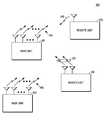
- FIG. 1illustrates a wireless communication system
- FIG. 2is a wireless communication infrastructure entity block diagram.
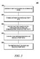
- FIG. 3is a wireless communication infrastructure entity process flow diagram.
- FIG. 4is a wireless communication user terminal block diagram.
- FIG. 5is a wireless communication user terminal process flow diagram.
- a wireless communication system 100comprises one or more fixed base infrastructure units forming a network distributed over a geographical region.
- the base unitmay also be referred to as an access point, access terminal, base, base station, Node-B, eNode-B or by other terminology used in the art.
- the one or more base units 101 and 102serve a number of remote units 103 and 110 within a serving area, for example, a cell or a cell sector.
- the remote unitsmay be fixed units or mobile terminals.
- the remote unitsmay also be referred to as subscriber units, mobiles, mobile stations, users, terminals, subscriber stations, user equipment (UE), terminals, or by other terminology used in the art.
- the base units 101 and 102transmit downlink communication signals 104 and 105 to serve remote units in the time and/or frequency domain.
- the remote units 103 and 110communicate with the one or more base units via uplink communication signals 106 and 113 .
- the one or more base unitsmay comprise one or more transmitters and one or more receivers for downlink and uplink transmissions.
- the remote unitsmay also comprise one or more transmitters and one or more receivers.
- the wireless communication systemis compliant with the developing Long Term Evolution (LTE) of the 3GPP Universal Mobile Telecommunications System (UMTS) protocol wherein base stations transmit using an orthogonal frequency division multiplexing (OFDM) modulation scheme on the downlink and the user terminals transmit on the uplink using a single carrier frequency division multiple access (SC-FDMA) scheme.
- LTELong Term Evolution
- UMTS3GPP Universal Mobile Telecommunications System
- SC-FDMAsingle carrier frequency division multiple access
- the wireless communication systemmay implement some other open or proprietary communication protocol.
- the present disclosureis not intended to be limited to the implementation of any particular wireless communication system architecture or protocol.
- each base stationand more generally some other wireless communication infrastructure entity, has a communication configuration.
- the communication configurationis an antenna configuration of the base station.
- LTELong Term Evolution
- UMTSUniversal Mobile Telecommunications Systems
- PBCHPhysical Broadcast Channel
- the UEis required to decode the PBCH without the assistance of base station antenna configuration information acquired during an earlier phase of the initial network access procedure since the base station does not explicitly signal the antenna configuration via the synchronization channel. Accordingly, a means for assisting the UE in discriminating the antenna configuration of the base station is desired in some instances, particularly where neighboring base stations have different configurations and/or where the antenna configuration of the base station changes dynamically. There may also be instances where it is desirable for the base station to signal the transmit antenna configuration that should be adopted by the terminal.
- the wireless communication infrastructure entitymay assist one or more entities with the determination of a communication configuration of the wireless communication infrastructure entity or with the determination of the communication configuration of or for the wireless communication terminal.
- the communication configuration informationmay be in the form of any one or more of the following: the antenna configuration of the wireless communication terminal; information on cell identity information (this can sometimes be transferred by association with, e.g., a synchronization channel identifier); information concerning the duration of frame or slot structure; the configuration of the cell as a paired, e.g., frequency-division duplexing (FDD) or unpaired, e.g.
- FDDfrequency-division duplexing
- time-division duplexing, (TDD) transmissionsymmetric or asymmetric downlink and uplink frequency resources; the type and/or number of transmitted pilot or reference symbols; whether broadcast or unicast service is supported; the presence of superposed channel transmissions; admission control data; the association of adjacent or non-adjacent spectrum; the number of accessible carriers or carrier relationships in case of a multi-carrier structure; the cell and carrier type and relationship to other cells in a hierarchical cell structure or multi-carrier hierarchical cell structure; a dedicated broadcast carrier in an SFN; among other information.
- TDDtime-division duplexing
- a wireless communication infrastructure entity 200 having a communication configurationcomprises a transceiver 210 communicably coupled a controller 220 .
- the wireless communication infrastructure entitycorresponds to one of the base units of FIG. 1 wherein the communication configuration is an antenna configuration.
- the transceivergenerally communicates with one or more user terminals within its coverage area.
- the controlleris most readily implemented as a digital processor controlled by software and/or firmware stored in memory 230 . Alternatively however the controller may be implemented as a hardware equivalent device or as a combination of hardware and software.
- the controllerincludes parity bit generation functionality 222 used to generate parity bits based on an information word that is to be transmitted to a user terminal.
- the controlleris configured to generate parity bits based on an information word.
- the wireless communication network infrastructure entitygenerate parity bits, for example, Cyclic Redundancy Check (CRC) bits based on an information word, for example a transport block.
- CRCCyclic Redundancy Check
- the parity bitsare combined with the information word.
- the controllerincludes parity bit encoding functionality 224 used to encode communication configuration information of the wireless communication infrastructure entity on the parity bits.
- the controlleris configured to encode the parity bits based on the communication configuration of the wireless communication infrastructure entity under software and/or firmware control. In other embodiments, more generally, other communication configuration information could be encoded on the parity bits.
- the controlleris configured to encode the parity bits by masking the parity bits with a unique set of configuration indicator bits corresponding to the communication configuration of the wireless communication infrastructure entity. In one implementation, the masking may be performed by XOR-ing the parity bits with the set of configuration indicator bits.
- the maskcould be generated by, for example, selecting 3 length-N masking words where N is the PBCH CRC parity field length (and is likely 16 bits) with maximum Hamming distance.
- Such a set of masking wordscould include, for example, the all-zero or null masking word corresponding to the 1 antenna configuration without loss of generality.
- the mask or parity field modifiercould also be conditioned on the base station physical cell ID, or the duration of a frame or slot structure, or the configuration of the cell as a paired, e.g., frequency-division duplexing (FDD) or unpaired, e.g., time-division duplexing, (TDD) transmission, symmetric or asymmetric downlink and uplink frequency resources, the type and number of transmitted pilot or reference symbols, the type of service supported (e.g., broadcast, unicast), the presence of superposed channel transmissions, admission control data, the association of adjacent or non-adjacent spectrum, the number of accessible carriers or carrier relationships in case of a multi-carrier structure, the cell and carrier type and relationship to other cells in a hierarchical cell structure or multi-carrier hierarchical cell structure, among other communication configuration information, some examples of which are discussed above.
- FDDfrequency-division duplexing
- TDDtime-division duplexing
- the information wordis generally combined or otherwise associated with the encoded parity bits before transmission to the user terminal.
- the controlleris configured to combine the information word and the parity bits by concatenating the parity bits to the information word, for example, at the beginning or end thereof, before or after the parity bits are encoded.
- the parity bitsmay be inserted into a mid portion of the information word or the parity bit may be interleaved with the information word before or after encoding.
- the wireless communication infrastructure entitycombines the information word and the parity bits and then at 330 encodes the parity bits based on the communication configuration of the wireless communication infrastructure entity.
- the parity bitsare first encoded and then combined with the information word.
- the spatial location or the order of the combining functionalityis not necessarily indicative of order in which it occurs relative to the parity bit encoding function.
- the controllerincludes channel coding functionality used to channel code the information word and the combined encoded parity bits before transmitting.
- the information word combined with the encoded parity bitsare channel coded before transmission at 350 .
- the controllercommunicates the channel coded information word and parity bits to the transceiver for transmission.
- a wireless communication user terminal 400comprises a transceiver 410 communicably coupled a controller 420 .
- the user terminalcorresponds to one of the remote units of FIG. 1 .
- the transceivergenerally communicates with one or more base units.
- the controlleris most readily implemented as a digital processor controlled by software and/or firmware stored in memory 430 . Alternatively however the controller may be implemented as a hardware equivalent device or as a combination of hardware and software.
- the user terminalreceives an information word combined with encoded parity bits from a wireless communication entity.
- the controllerincludes functionality 422 used to identify a set of configuration indicator bits used to encode parity bits that are combined with an information word.
- the controlleralso includes functionality 424 used to determine a communication configuration based on the set of configuration indicator bits used to encode the parity bits.
- the controlleris configured to determine a communication configuration of the wireless communication entity from which the combination of the information word and the encoded parity bits were received based on the set of configuration indicator bits used to encode the parity bits.
- the controlleris configured to determine a communication configuration of the wireless communication user terminal based on the set of configuration indicator bits used to encode the parity bits.
- the user terminalrecovers the parity bits from the encoded parity bits.
- the parity bitsare recovered by XOR-ing the encoded parity bits with a set of configuration indicator bits.
- the user terminalperforms error detection on an information word using the recovered parity bits.
- the user terminalperforms the XOR-ing process for each possible set of configuration indicator bits, wherein the set of configuration indicator bits indicative of the communication configuration of the wireless communication entity corresponds to the set of configuration indicator bits for which the detected errors in the information word is relatively low.
- the errors detectedmay be zero or at least less than the detected error associated with the other configuration indicator bits.
- the communication configuration of the wireless communication entityis indicated by not more than one set of configuration indicator bits.
Landscapes
- Engineering & Computer Science (AREA)
- Signal Processing (AREA)
- Computer Networks & Wireless Communication (AREA)
- Quality & Reliability (AREA)
- Mobile Radio Communication Systems (AREA)
- Detection And Prevention Of Errors In Transmission (AREA)
- Error Detection And Correction (AREA)
- Radio Transmission System (AREA)
- Digital Transmission Methods That Use Modulated Carrier Waves (AREA)
Abstract
Description
Claims (6)
Priority Applications (16)
| Application Number | Priority Date | Filing Date | Title |
|---|---|---|---|
| US12/112,577US8458558B2 (en) | 2008-04-30 | 2008-04-30 | Multi-antenna configuration signaling in wireless communication system |
| RU2010148784/08ARU2482607C2 (en) | 2008-04-30 | 2009-04-30 | Multi-antenna configuration signalling in wireless communication system |
| EP12193643AEP2568641A1 (en) | 2008-04-30 | 2009-04-30 | Multi-antenna configuration signaling in wireless communication system |
| CN200980114902.5ACN102084596B (en) | 2008-04-30 | 2009-04-30 | Multi-antenna configuration signaling in wireless communication system |
| EP09739761AEP2274851B1 (en) | 2008-04-30 | 2009-04-30 | Multi-antenna configuration signaling in wireless communication system |
| EP12193645AEP2568642A1 (en) | 2008-04-30 | 2009-04-30 | Multi-antenna configuration signaling in wireless communication system |
| EP12193646AEP2568643A1 (en) | 2008-04-30 | 2009-04-30 | Multi-antenna configuration signaling in wireless communication system |
| PCT/US2009/042215WO2009134959A2 (en) | 2008-04-30 | 2009-04-30 | Multi-antenna configuration signaling in wireless communication system |
| PL09739761TPL2274851T3 (en) | 2008-04-30 | 2009-04-30 | Multi-antenna configuration signaling in wireless communication system |
| ES09739761TES2397686T3 (en) | 2008-04-30 | 2009-04-30 | Multi-antenna configuration signaling in a wireless communication system |
| BRPI0910434-8ABRPI0910434B1 (en) | 2008-04-30 | 2009-04-30 | WIRELESS COMMUNICATION INFRASTRUCTURE ENTITY HAVING A COMMUNICATION SETUP AND WIRELESS USER TERMINAL |
| KR1020107026946AKR101226366B1 (en) | 2008-04-30 | 2009-04-30 | Multi-antenna configuration signaling in wireless communication system |
| MX2010011779AMX2010011779A (en) | 2008-04-30 | 2009-04-30 | Multi-antenna configuration signaling in wireless communication system. |
| JP2011506502AJP5147989B2 (en) | 2008-04-30 | 2009-04-30 | Signal transmission of multiple antenna configurations in wireless communication systems |
| US13/399,020US8484530B2 (en) | 2008-04-30 | 2012-02-17 | Multi-antenna configuration signaling in wireless communication system |
| JP2012216389AJP5763031B2 (en) | 2008-04-30 | 2012-09-28 | Signal transmission of multiple antenna configurations in wireless communication systems |
Applications Claiming Priority (1)
| Application Number | Priority Date | Filing Date | Title |
|---|---|---|---|
| US12/112,577US8458558B2 (en) | 2008-04-30 | 2008-04-30 | Multi-antenna configuration signaling in wireless communication system |
Related Child Applications (1)
| Application Number | Title | Priority Date | Filing Date |
|---|---|---|---|
| US13/399,020ContinuationUS8484530B2 (en) | 2008-04-30 | 2012-02-17 | Multi-antenna configuration signaling in wireless communication system |
Publications (2)
| Publication Number | Publication Date |
|---|---|
| US20090276684A1 US20090276684A1 (en) | 2009-11-05 |
| US8458558B2true US8458558B2 (en) | 2013-06-04 |
Family
ID=41255788
Family Applications (2)
| Application Number | Title | Priority Date | Filing Date |
|---|---|---|---|
| US12/112,577Active2032-01-07US8458558B2 (en) | 2008-04-30 | 2008-04-30 | Multi-antenna configuration signaling in wireless communication system |
| US13/399,020ActiveUS8484530B2 (en) | 2008-04-30 | 2012-02-17 | Multi-antenna configuration signaling in wireless communication system |
Family Applications After (1)
| Application Number | Title | Priority Date | Filing Date |
|---|---|---|---|
| US13/399,020ActiveUS8484530B2 (en) | 2008-04-30 | 2012-02-17 | Multi-antenna configuration signaling in wireless communication system |
Country Status (11)
| Country | Link |
|---|---|
| US (2) | US8458558B2 (en) |
| EP (4) | EP2568641A1 (en) |
| JP (2) | JP5147989B2 (en) |
| KR (1) | KR101226366B1 (en) |
| CN (1) | CN102084596B (en) |
| BR (1) | BRPI0910434B1 (en) |
| ES (1) | ES2397686T3 (en) |
| MX (1) | MX2010011779A (en) |
| PL (1) | PL2274851T3 (en) |
| RU (1) | RU2482607C2 (en) |
| WO (1) | WO2009134959A2 (en) |
Families Citing this family (13)
| Publication number | Priority date | Publication date | Assignee | Title |
|---|---|---|---|---|
| US8144712B2 (en) | 2008-08-07 | 2012-03-27 | Motorola Mobility, Inc. | Scheduling grant information signaling in wireless communication system |
| US8676133B2 (en)* | 2008-09-19 | 2014-03-18 | Qualcomm Incorporated | Reference signal design for LTE A |
| CN101729131B (en)* | 2008-11-03 | 2014-06-04 | 夏普株式会社 | Wireless communication system and pre-coding method |
| WO2010072020A1 (en) | 2008-12-22 | 2010-07-01 | Huawei Technologies Co., Ltd. | Method for signalling in a wireless communication system |
| KR101691835B1 (en)* | 2009-05-27 | 2017-01-02 | 엘지전자 주식회사 | Method of indicating number of antennas in network broadcast system |
| EP2282418A3 (en)* | 2009-06-23 | 2011-03-09 | Alcatel Lucent | A station comprising at least two transmit antennas, and a method of transmitting therefrom |
| US20130142060A1 (en)* | 2010-02-26 | 2013-06-06 | Qualcomm Incorporated | Instantaneous noise normalized searcher metrics |
| US8675579B2 (en)* | 2010-05-03 | 2014-03-18 | Futurewei Technologies, Inc. | System and method for allocating network resources for a communications link |
| JP2011259128A (en)* | 2010-06-08 | 2011-12-22 | Nec Corp | Digital data transmission system, transmitter, receiver, and transmission method |
| WO2015030547A1 (en)* | 2013-08-31 | 2015-03-05 | 엘지전자 주식회사 | Method and apparatus for receiving signal in wireless access system supporting fdr transmission |
| JP6991234B2 (en)* | 2017-03-23 | 2022-01-12 | クアルコム,インコーポレイテッド | Parity bit channel allocation for polar coding |
| BR112019021707A2 (en) | 2017-04-20 | 2020-05-12 | Qualcomm Incorporated | DYNAMIC FROZEN BITS AND ERROR DETECTION FOR POLAR CODES |
| CN109698738B (en)* | 2017-10-24 | 2022-04-29 | 华为技术有限公司 | Communication method and communication device |
Citations (35)
| Publication number | Priority date | Publication date | Assignee | Title |
|---|---|---|---|---|
| US5862160A (en)* | 1996-12-31 | 1999-01-19 | Ericsson, Inc. | Secondary channel for communication networks |
| WO2001082543A2 (en) | 2000-04-22 | 2001-11-01 | Atheros Communications, Inc. | Multi-carrier communication systems employing variable ofdm-symbol rates and number of carriers |
| US20020194571A1 (en)* | 2001-06-13 | 2002-12-19 | Michael Parr | System and method of coding cyclic redundancy check bits to enhance frequency reuse in a communications network |
| US20030060173A1 (en)* | 2001-08-18 | 2003-03-27 | Samsung Electronics Co., Ltd. | Apparatus and method for transmitting and receiving data using an antenna array in a mobile communication system |
| US6678854B1 (en)* | 1999-10-12 | 2004-01-13 | Ericsson, Inc. | Methods and systems for providing a second data signal on a frame of bits including a first data signal and an error-correcting code |
| US6738946B1 (en)* | 2000-08-08 | 2004-05-18 | Telefonaktiebolaget L.M. Ericsson | Methods, communication devices, and computer program products for communicating information via a frame check sequence having an information block associated therewith |
| WO2005048625A1 (en) | 2003-11-17 | 2005-05-26 | Telefonaktiebolaget Lm Ericsson (Publ) | Encapsulation of diverse protocols over internal interface of distributed radio base station |
| WO2005050852A2 (en) | 2003-11-18 | 2005-06-02 | Interdigital Technology Corporation | Method and system for providing channel assignment information used to support uplink and downlink channels |
| US20050250454A1 (en) | 2004-05-06 | 2005-11-10 | Benoist Sebire | Redundancy version implementation for an uplink enhanced dedicated channel |
| US20060067229A1 (en) | 2004-09-29 | 2006-03-30 | Nokia Corporation | Transmitting data in a wireless network |
| US7149538B2 (en) | 2003-02-13 | 2006-12-12 | Telefonaktiebolaget Lm Ericsson (Publ) | Wireless transceivers, methods, and computer program products for restricting transmission power based on signal-to-interference ratios |
| US20060285515A1 (en) | 2005-06-16 | 2006-12-21 | Qualcomm Incorporated | Methods and apparatus for efficient providing of scheduling information |
| US20070025454A1 (en) | 2005-07-26 | 2007-02-01 | Ipwireless, Inc. | Interference mitigation for orthogonal frequency division multiplexing communication |
| US20070195809A1 (en) | 2006-02-22 | 2007-08-23 | Qualcomm Incorporated | Method and Apparatus for Sending Signaling Information via Channel IDS |
| US7318185B2 (en) | 2001-08-23 | 2008-01-08 | Nortel Networks Limited | Method and apparatus for scrambling based peak-to-average power ratio reduction without side information |
| EP1881662A1 (en) | 2006-07-18 | 2008-01-23 | Siemens Aktiengesellschaft | Filter adjustment depending on the occupancy of the neighbouring band |
| WO2008024788A2 (en) | 2006-08-21 | 2008-02-28 | Qualcomm Incorporated | Method and apparatus for random access in an orthogonal multiple-access communication system |
| US20080146242A1 (en) | 2006-12-18 | 2008-06-19 | Nokia Corporation | Method for requesting an uplink resource allocation during a downlink data transmission |
| US20080192872A1 (en) | 2007-02-14 | 2008-08-14 | Bengt Lindoff | Multi transmit antenna synchronization channell transmission cell id detection |
| US20080285512A1 (en) | 2007-05-01 | 2008-11-20 | Interdigital Technology Corporation | Method and apparatus for reducing modulation, coding and transport block information signaling overhead |
| US20090037797A1 (en) | 2007-07-30 | 2009-02-05 | Spencer Paul S | Rate matching for a wireless communications systems |
| US20090122776A1 (en) | 2007-11-09 | 2009-05-14 | Bjorn Folkstedt | System and method of verification of hsdpa layer 1 coding in a node |
| US20090149207A1 (en)* | 2007-12-07 | 2009-06-11 | Samsung Electronics Co., Ltd. | Physical broadcast channel (PBCH) transmission for reliable detection of antenna configuration |
| US20090176463A1 (en)* | 2008-01-04 | 2009-07-09 | Nokia Corporation | Method and apparatus for conveying antenna configuration information |
| US20090197630A1 (en) | 2008-02-04 | 2009-08-06 | Ahn Seung Jin | Method of controlling transmit power of uplink channel |
| US20090221293A1 (en) | 2005-12-13 | 2009-09-03 | Matsushita Electric Industrial Co., Ltd | Transmission and reception of broadcast system information in a mobile comunication system |
| US20090245194A1 (en) | 2008-03-28 | 2009-10-01 | Qualcomm Incorporated | Dynamic assignment of ack resource in a wireless communication system |
| WO2009129343A1 (en) | 2008-04-15 | 2009-10-22 | Qualcomm Incorporated | Physical harq indicator channel (phich) resource assignment signaling in a wireless communication environment |
| US20090262854A1 (en) | 2008-04-18 | 2009-10-22 | Lg Electronics Inc. | Method for transmitting and receiving downlink control information |
| US20090279460A1 (en) | 2008-05-07 | 2009-11-12 | Qualcomm Incorporated | Bundling of ack information in a wireless communication system |
| US7697483B2 (en)* | 2005-04-04 | 2010-04-13 | Ntt Docomo, Inc. | Transmitting method, receiving method, radio base station, and mobile station |
| US20100238875A1 (en) | 2007-08-13 | 2010-09-23 | Doo Hyun Sung | Method for transmitting voip packet |
| US20100272037A1 (en) | 2007-10-23 | 2010-10-28 | Lg Electronics Inc. | Method of transmitting broadcasting information |
| US7986758B2 (en) | 2008-05-30 | 2011-07-26 | Telefonaktiebolaget Lm Ericsson (Publ) | Synchronization detection using bandwidth and antenna configuration |
| US8290088B2 (en) | 2007-08-07 | 2012-10-16 | Research In Motion Limited | Detecting the number of transmit antennas in a base station |
Family Cites Families (9)
| Publication number | Priority date | Publication date | Assignee | Title |
|---|---|---|---|---|
| RU2233032C2 (en)* | 2000-05-25 | 2004-07-20 | Самсунг Электроникс Ко., Лтд. | Device and method for diversity transmission using more than two antennas |
| US7039356B2 (en)* | 2002-03-12 | 2006-05-02 | Blue7 Communications | Selecting a set of antennas for use in a wireless communication system |
| KR100981554B1 (en)* | 2003-11-13 | 2010-09-10 | 한국과학기술원 | In a mobile communication system having multiple transmit / receive antennas, a method of transmitting signals by grouping transmit antennas |
| KR100706634B1 (en)* | 2004-11-12 | 2007-04-11 | 한국전자통신연구원 | Improved multi-antenna system |
| JP4819897B2 (en)* | 2005-08-22 | 2011-11-24 | クゥアルコム・インコーポレイテッド | Method and apparatus for selecting a virtual antenna |
| US8068872B2 (en)* | 2005-10-06 | 2011-11-29 | Telefonaktiebolaget Lm Ericsson (Publ) | Signaling support for antenna selection using subset lists and subset masks |
| JP4979224B2 (en)* | 2005-11-08 | 2012-07-18 | シャープ株式会社 | Reception device, transmission device, and communication method |
| EP2041996A2 (en) | 2006-06-01 | 2009-04-01 | Personics Holdings Inc. | Ear input sound pressure level monitoring system |
| US8144712B2 (en) | 2008-08-07 | 2012-03-27 | Motorola Mobility, Inc. | Scheduling grant information signaling in wireless communication system |
- 2008
- 2008-04-30USUS12/112,577patent/US8458558B2/enactiveActive
- 2009
- 2009-04-30RURU2010148784/08Apatent/RU2482607C2/enactive
- 2009-04-30KRKR1020107026946Apatent/KR101226366B1/enactiveActive
- 2009-04-30EPEP12193643Apatent/EP2568641A1/ennot_activeWithdrawn
- 2009-04-30CNCN200980114902.5Apatent/CN102084596B/enactiveActive
- 2009-04-30WOPCT/US2009/042215patent/WO2009134959A2/enactiveApplication Filing
- 2009-04-30PLPL09739761Tpatent/PL2274851T3/enunknown
- 2009-04-30BRBRPI0910434-8Apatent/BRPI0910434B1/enactiveIP Right Grant
- 2009-04-30EPEP12193645Apatent/EP2568642A1/ennot_activeWithdrawn
- 2009-04-30EPEP09739761Apatent/EP2274851B1/enactiveActive
- 2009-04-30EPEP12193646Apatent/EP2568643A1/ennot_activeWithdrawn
- 2009-04-30JPJP2011506502Apatent/JP5147989B2/enactiveActive
- 2009-04-30MXMX2010011779Apatent/MX2010011779A/enactiveIP Right Grant
- 2009-04-30ESES09739761Tpatent/ES2397686T3/enactiveActive
- 2012
- 2012-02-17USUS13/399,020patent/US8484530B2/enactiveActive
- 2012-09-28JPJP2012216389Apatent/JP5763031B2/enactiveActive
Patent Citations (39)
| Publication number | Priority date | Publication date | Assignee | Title |
|---|---|---|---|---|
| US5862160A (en)* | 1996-12-31 | 1999-01-19 | Ericsson, Inc. | Secondary channel for communication networks |
| US6678854B1 (en)* | 1999-10-12 | 2004-01-13 | Ericsson, Inc. | Methods and systems for providing a second data signal on a frame of bits including a first data signal and an error-correcting code |
| WO2001082543A2 (en) | 2000-04-22 | 2001-11-01 | Atheros Communications, Inc. | Multi-carrier communication systems employing variable ofdm-symbol rates and number of carriers |
| US6738946B1 (en)* | 2000-08-08 | 2004-05-18 | Telefonaktiebolaget L.M. Ericsson | Methods, communication devices, and computer program products for communicating information via a frame check sequence having an information block associated therewith |
| US20020194571A1 (en)* | 2001-06-13 | 2002-12-19 | Michael Parr | System and method of coding cyclic redundancy check bits to enhance frequency reuse in a communications network |
| US20030060173A1 (en)* | 2001-08-18 | 2003-03-27 | Samsung Electronics Co., Ltd. | Apparatus and method for transmitting and receiving data using an antenna array in a mobile communication system |
| US7318185B2 (en) | 2001-08-23 | 2008-01-08 | Nortel Networks Limited | Method and apparatus for scrambling based peak-to-average power ratio reduction without side information |
| US7149538B2 (en) | 2003-02-13 | 2006-12-12 | Telefonaktiebolaget Lm Ericsson (Publ) | Wireless transceivers, methods, and computer program products for restricting transmission power based on signal-to-interference ratios |
| WO2005048625A1 (en) | 2003-11-17 | 2005-05-26 | Telefonaktiebolaget Lm Ericsson (Publ) | Encapsulation of diverse protocols over internal interface of distributed radio base station |
| CN1883217A (en) | 2003-11-17 | 2006-12-20 | 艾利森电话股份有限公司 | Encapsulation of diverse protocols over internal interface of distributed radio base station |
| JP2007511965A (en) | 2003-11-18 | 2007-05-10 | インターデイジタル テクノロジー コーポレーション | Method and system for providing channel assignment information used to support uplink and downlink channels |
| WO2005050852A2 (en) | 2003-11-18 | 2005-06-02 | Interdigital Technology Corporation | Method and system for providing channel assignment information used to support uplink and downlink channels |
| US20050250454A1 (en) | 2004-05-06 | 2005-11-10 | Benoist Sebire | Redundancy version implementation for an uplink enhanced dedicated channel |
| US20060067229A1 (en) | 2004-09-29 | 2006-03-30 | Nokia Corporation | Transmitting data in a wireless network |
| US7697483B2 (en)* | 2005-04-04 | 2010-04-13 | Ntt Docomo, Inc. | Transmitting method, receiving method, radio base station, and mobile station |
| US20060285515A1 (en) | 2005-06-16 | 2006-12-21 | Qualcomm Incorporated | Methods and apparatus for efficient providing of scheduling information |
| US20070025454A1 (en) | 2005-07-26 | 2007-02-01 | Ipwireless, Inc. | Interference mitigation for orthogonal frequency division multiplexing communication |
| US20090221293A1 (en) | 2005-12-13 | 2009-09-03 | Matsushita Electric Industrial Co., Ltd | Transmission and reception of broadcast system information in a mobile comunication system |
| US20070195809A1 (en) | 2006-02-22 | 2007-08-23 | Qualcomm Incorporated | Method and Apparatus for Sending Signaling Information via Channel IDS |
| US20090325589A1 (en) | 2006-07-18 | 2009-12-31 | Siemens Aktiengesellschaft | Filter Arrangement Dependent on Occupation of an Adjacent Band |
| EP1881662A1 (en) | 2006-07-18 | 2008-01-23 | Siemens Aktiengesellschaft | Filter adjustment depending on the occupancy of the neighbouring band |
| WO2008024788A2 (en) | 2006-08-21 | 2008-02-28 | Qualcomm Incorporated | Method and apparatus for random access in an orthogonal multiple-access communication system |
| US20080146242A1 (en) | 2006-12-18 | 2008-06-19 | Nokia Corporation | Method for requesting an uplink resource allocation during a downlink data transmission |
| US20080192872A1 (en) | 2007-02-14 | 2008-08-14 | Bengt Lindoff | Multi transmit antenna synchronization channell transmission cell id detection |
| US20080285512A1 (en) | 2007-05-01 | 2008-11-20 | Interdigital Technology Corporation | Method and apparatus for reducing modulation, coding and transport block information signaling overhead |
| US20090037797A1 (en) | 2007-07-30 | 2009-02-05 | Spencer Paul S | Rate matching for a wireless communications systems |
| US8290088B2 (en) | 2007-08-07 | 2012-10-16 | Research In Motion Limited | Detecting the number of transmit antennas in a base station |
| US20100238875A1 (en) | 2007-08-13 | 2010-09-23 | Doo Hyun Sung | Method for transmitting voip packet |
| US20100272037A1 (en) | 2007-10-23 | 2010-10-28 | Lg Electronics Inc. | Method of transmitting broadcasting information |
| US20090122776A1 (en) | 2007-11-09 | 2009-05-14 | Bjorn Folkstedt | System and method of verification of hsdpa layer 1 coding in a node |
| US20090149207A1 (en)* | 2007-12-07 | 2009-06-11 | Samsung Electronics Co., Ltd. | Physical broadcast channel (PBCH) transmission for reliable detection of antenna configuration |
| US20090176463A1 (en)* | 2008-01-04 | 2009-07-09 | Nokia Corporation | Method and apparatus for conveying antenna configuration information |
| US20090197630A1 (en) | 2008-02-04 | 2009-08-06 | Ahn Seung Jin | Method of controlling transmit power of uplink channel |
| US20090245194A1 (en) | 2008-03-28 | 2009-10-01 | Qualcomm Incorporated | Dynamic assignment of ack resource in a wireless communication system |
| WO2009129343A1 (en) | 2008-04-15 | 2009-10-22 | Qualcomm Incorporated | Physical harq indicator channel (phich) resource assignment signaling in a wireless communication environment |
| JP2011517259A (en) | 2008-04-15 | 2011-05-26 | クゥアルコム・インコーポレイテッド | Physical HARQ Indicator Channel (PHICH) resource allocation signaling in a wireless communication environment |
| US20090262854A1 (en) | 2008-04-18 | 2009-10-22 | Lg Electronics Inc. | Method for transmitting and receiving downlink control information |
| US20090279460A1 (en) | 2008-05-07 | 2009-11-12 | Qualcomm Incorporated | Bundling of ack information in a wireless communication system |
| US7986758B2 (en) | 2008-05-30 | 2011-07-26 | Telefonaktiebolaget Lm Ericsson (Publ) | Synchronization detection using bandwidth and antenna configuration |
Non-Patent Citations (29)
| Title |
|---|
| 3GPP TSG RAN WG1 #51 Meeting; R1-074861; Jeju, Korea; Nov. 5-9, 2007; 5 Pages. |
| 3GPP TSG RAN WG1 #51BIS Meeting; R1-080586; Sevilla, Spain; January. 14-18, 2008; 1 Page. |
| 3GPP TSG RAN WG1 #51bis Meeting; Sevilla, Spain; Jan. 14-18, 2008; Nokia Siemens Networks, Nokia, Panasonic, Texas Instruments, Motorola, Samsung, CMCC, CATT, Ericsson, Nortel, Huawei, LGE; Way Forward on PBCH for FDD and TDD; R1-080586; 2 pages. |
| 3GPP TSG RAN WG1 #51bis, R1-080328 "Remaining Issues on RV Signalling for HARQ" Nokia Siemens Networks et al., Sevilla, Spain, Jan. 14-18, 2008, 5 pages. |
| 3GPP TSG RAN WG1 #52 Meeting; Sorrento, Italy, Feb. 11-15, 2008; Nokia Siemens Networks, Nokia; CRC Mask Selection for PBCH; R1-081073; 8 pages. |
| 3GPP TSG RAN WG1 #52, R1-080869 "Summary of Email Discussion on DL Control Signaling" Ericsson, Sorrento, Italy, Feb. 11-15, 2008, 8 pages. |
| 3GPP TSG RAN WG1 #AH , R1-041072 "HARQ Protocol for HSUPA" Panasonic, Seoul, Korea Sep. 20-24, 2004, 3 pages. |
| 3GPP TSG RAN WG2 #59bis; R2-074159 "Radio Connection Control IEs" Panasonic; Shanghai, China; Oct. 8-12, 2007; 19 pages. |
| 3GPP TSG RAN1 #48bis; Malta; Mar. 26-30, 2007; Motorola; E-UTRA DL L1/L2 Control Channel Design; R1-071353; 6 pages. |
| 3GPP TSG RAN1 #51; Sevilla, Spain; Jan. 14-18, 2008; Motorola; Antenna Configuration Detection Based on Reference Signal Energy; R1-080434; 12 pages. |
| 3GPP TSG RAN1 #51bis Meeting; Sevilla, Spain; Jan. 14-18, 2008; Nokia Siemens Networks, Nokia, China Mobile, Huawei; Issues with PBCH-based Blind Antenna Configuration Detection; R1-080324; 8 pages. |
| 3GPP TSG RAN1 #53; Kansas City, USA; May 5-9, 2008; Motorola; Definition of DCI Format 1C; R1-082059; 6 pages. |
| 3GPP TSG RAN1 #53bis.; Warsaw Poland; Jun. 30-Jul. 4, 2008; Motorola; Further Definition of DCI Format 1C; R1-082333; 9 pages. |
| 3GPP TSG-RAN Meeting #50-BIS; R1-073970; Shanghai, China; Oct. 8-12, 2007; 9 Pages. |
| 3GPP TSG-RAN WG2 Meeting #61; Sorrento, Italy; Feb. 11-15, 2008; Qualcomm Europe; Allocation of Semi-Persistent Resources; R2-081072; 1 page. |
| European Patent Office "European Extended Search Report" for European Patent Application No. 12193643.9 dated Feb. 7, 2013, 7 pages. |
| European Patent Office "European Extended Search Report" for European Patent Application No. 12193645.4 dated Feb. 7, 2013, 7 pages. |
| European Patent Office "European Extended Search Report" for European Patent Application No. 12193646.2 dated Feb. 7, 2013, 6 pages. |
| European Patent Office, "Extended Search Report" for European Application No. 12000351.2 Apr. 26, 2012, 5 pages. |
| European Patent Office, "Extended Search Report" for European Application No. 12000352.0 Apr. 26, 2012, 5 pages. |
| Japan Notice of Reasons for Rejection (Translated) for Application No. 2009-174876 dated Oct. 18, 2011, 3 pages. |
| PCT Search Report and Written Opinion; Mar. 4, 2010; PCT/US2009/042215; 18 pages. |
| PCT Search Report and Written Opinion; Mar. 4, 2010; PCT/US2009/050346; 18 pages. |
| The State Intellectual Property Office of the Pople's Republic of China "Notification of the First Office Action" for Chinese Patent Appliction No. 200980114902.5 dated Jan. 4, 2013, 6 pages. |
| United States Patent and Trademark Office, "Non-Final Rejection" for U.S. Appl. No. 12/188,053 May 3, 2011, 22 pages. |
| United States Patent and Trademark Office, "Non-Final Rejection" for U.S. Appl. No. 12/188,053 Oct. 14, 2011, 23 pages. |
| United States Patent and Trademark Office, "Non-Final Rejection" for U.S. Appl. No. 13/399,020 Dec. 6, 2012, 9 pages. |
| United States Patent and Trademark Office, "Non-Final Rejection" for U.S. Appl. No. 13/417,478 Jan. 4, 2013, 20 pages. |
| USPTO; U.S. Appl. No. 12/188,053, filed Aug. 7, 2008; Confirmation #4233. |
Also Published As
| Publication number | Publication date |
|---|---|
| EP2568641A1 (en) | 2013-03-13 |
| JP2013042519A (en) | 2013-02-28 |
| PL2274851T3 (en) | 2013-04-30 |
| WO2009134959A3 (en) | 2010-04-22 |
| US20120151306A1 (en) | 2012-06-14 |
| EP2274851A2 (en) | 2011-01-19 |
| CN102084596B (en) | 2014-03-05 |
| KR20110008309A (en) | 2011-01-26 |
| EP2568642A1 (en) | 2013-03-13 |
| JP5147989B2 (en) | 2013-02-20 |
| JP2011522457A (en) | 2011-07-28 |
| MX2010011779A (en) | 2011-02-23 |
| JP5763031B2 (en) | 2015-08-12 |
| BRPI0910434B1 (en) | 2020-09-15 |
| BRPI0910434A2 (en) | 2015-09-29 |
| ES2397686T3 (en) | 2013-03-08 |
| EP2274851B1 (en) | 2013-01-02 |
| CN102084596A (en) | 2011-06-01 |
| BRPI0910434A8 (en) | 2019-01-15 |
| US20090276684A1 (en) | 2009-11-05 |
| KR101226366B1 (en) | 2013-01-24 |
| RU2010148784A (en) | 2012-06-10 |
| US8484530B2 (en) | 2013-07-09 |
| EP2568643A1 (en) | 2013-03-13 |
| WO2009134959A2 (en) | 2009-11-05 |
| RU2482607C2 (en) | 2013-05-20 |
Similar Documents
| Publication | Publication Date | Title |
|---|---|---|
| US8458558B2 (en) | Multi-antenna configuration signaling in wireless communication system | |
| CN109347611B (en) | Downlink control channel design method | |
| US20220191080A1 (en) | Wireless communications device, infrastructure equipment and methods | |
| CN114884619B (en) | CRC bits for joint decoding and verification of control information using polarization codes | |
| RU2387101C2 (en) | High-speed paging channel with low probability of loss of paging message | |
| US9520978B2 (en) | Apparatus, system, and method for signaling a quantity of antenna ports in a wireless communication system | |
| EP3592026B1 (en) | Wireless vehicular communications involving retransmission of messages | |
| CN108347293B (en) | Transmission method and device | |
| CN114223140B (en) | Method and device for sending and receiving multiple data in a wireless cooperative communication system | |
| US10757740B2 (en) | Method for transmitting or receiving signals in wireless communication system and apparatus therefor | |
| EP3602937A1 (en) | Communications device, infrastrcuture equipment and methods | |
| CN110830159B (en) | A wireless communication method, device and computer-readable storage medium | |
| US20240243882A1 (en) | Transmission of signalling information | |
| CN102165712B (en) | Method for signaling in a wireless communication system | |
| HK40011805A (en) | Crc bits for joint decoding and verification of control information using polar codes | |
| HK40011805B (en) | Crc bits for joint decoding and verification of control information using polar codes |
Legal Events
| Date | Code | Title | Description |
|---|---|---|---|
| AS | Assignment | Owner name:MOTOROLA INC, ILLINOIS Free format text:ASSIGNMENT OF ASSIGNORS INTEREST;ASSIGNORS:STEWART, KENNETH A;BROWN, TYLER A;LOVE, ROBERT T;REEL/FRAME:020880/0471 Effective date:20080430 | |
| AS | Assignment | Owner name:MOTOROLA MOBILITY, INC, ILLINOIS Free format text:ASSIGNMENT OF ASSIGNORS INTEREST;ASSIGNOR:MOTOROLA, INC;REEL/FRAME:025673/0558 Effective date:20100731 | |
| AS | Assignment | Owner name:MOTOROLA MOBILITY LLC, ILLINOIS Free format text:ASSIGNMENT OF ASSIGNORS INTEREST;ASSIGNOR:MOTOROLA MOBILITY, INC.;REEL/FRAME:028829/0856 Effective date:20120622 | |
| STCF | Information on status: patent grant | Free format text:PATENTED CASE | |
| AS | Assignment | Owner name:GOOGLE TECHNOLOGY HOLDINGS LLC, CALIFORNIA Free format text:ASSIGNMENT OF ASSIGNORS INTEREST;ASSIGNOR:MOTOROLA MOBILITY LLC;REEL/FRAME:034371/0612 Effective date:20141028 | |
| FPAY | Fee payment | Year of fee payment:4 | |
| MAFP | Maintenance fee payment | Free format text:PAYMENT OF MAINTENANCE FEE, 8TH YEAR, LARGE ENTITY (ORIGINAL EVENT CODE: M1552); ENTITY STATUS OF PATENT OWNER: LARGE ENTITY Year of fee payment:8 | |
| MAFP | Maintenance fee payment | Free format text:PAYMENT OF MAINTENANCE FEE, 12TH YEAR, LARGE ENTITY (ORIGINAL EVENT CODE: M1553); ENTITY STATUS OF PATENT OWNER: LARGE ENTITY Year of fee payment:12 |