US8457761B2 - System and method for promoting diuresis and natriuresis by the application of electric fields to the kidney - Google Patents
System and method for promoting diuresis and natriuresis by the application of electric fields to the kidneyDownload PDFInfo
- Publication number
- US8457761B2 US8457761B2US12/683,553US68355310AUS8457761B2US 8457761 B2US8457761 B2US 8457761B2US 68355310 AUS68355310 AUS 68355310AUS 8457761 B2US8457761 B2US 8457761B2
- Authority
- US
- United States
- Prior art keywords
- electric field
- sensor
- implantable
- constituent
- kidney
- Prior art date
- Legal status (The legal status is an assumption and is not a legal conclusion. Google has not performed a legal analysis and makes no representation as to the accuracy of the status listed.)
- Expired - Fee Related, expires
Links
Images


Classifications
- A—HUMAN NECESSITIES
- A61—MEDICAL OR VETERINARY SCIENCE; HYGIENE
- A61N—ELECTROTHERAPY; MAGNETOTHERAPY; RADIATION THERAPY; ULTRASOUND THERAPY
- A61N1/00—Electrotherapy; Circuits therefor
- A61N1/18—Applying electric currents by contact electrodes
- A61N1/32—Applying electric currents by contact electrodes alternating or intermittent currents
- A61N1/325—Applying electric currents by contact electrodes alternating or intermittent currents for iontophoresis, i.e. transfer of media in ionic state by an electromotoric force into the body
- A—HUMAN NECESSITIES
- A61—MEDICAL OR VETERINARY SCIENCE; HYGIENE
- A61N—ELECTROTHERAPY; MAGNETOTHERAPY; RADIATION THERAPY; ULTRASOUND THERAPY
- A61N1/00—Electrotherapy; Circuits therefor
- A61N1/18—Applying electric currents by contact electrodes
- A61N1/20—Applying electric currents by contact electrodes continuous direct currents
- A61N1/30—Apparatus for iontophoresis, i.e. transfer of media in ionic state by an electromotoric force into the body, or cataphoresis
- A61N1/303—Constructional details
- A61N1/306—Arrangements where at least part of the apparatus is introduced into the body
- A—HUMAN NECESSITIES
- A61—MEDICAL OR VETERINARY SCIENCE; HYGIENE
- A61N—ELECTROTHERAPY; MAGNETOTHERAPY; RADIATION THERAPY; ULTRASOUND THERAPY
- A61N1/00—Electrotherapy; Circuits therefor
- A61N1/18—Applying electric currents by contact electrodes
- A61N1/32—Applying electric currents by contact electrodes alternating or intermittent currents
- A61N1/36—Applying electric currents by contact electrodes alternating or intermittent currents for stimulation
- A61N1/36007—Applying electric currents by contact electrodes alternating or intermittent currents for stimulation of urogenital or gastrointestinal organs, e.g. for incontinence control
Definitions
- Heart failureis a complex syndrome resulting from the inability of the heart to pump blood sufficient to meet the body's needs.
- Heart failureis a progressive disease most common in the elderly and usually caused by other diseases/conditions that gradually damage the heart such as coronary heart disease, damaged heart valves, external pressure around the heart, and cardiac muscle disease.
- the kidneysplay an important role in compensating for the heart's inability to pump blood.
- healthy kidneysare responsible for various functions such as: removal of fluid and wastes; maintenance of blood pressure; maintenance of salt, water, electrolyte and acid-base balance; stimulation of red cell production (via the release of erythropoietin); and promotion of calcium absorption.
- cardiac and renal dysfunctionlead to fluid overload, which is often manifested as excess lung fluid (pulmonary edema) and dyspnea.
- the primary functional unit of the kidneysis called the “nephron.”
- Each kidneyconsists of about one million nephrons.
- a group of interconnected capillary loopscalled the glomerulus, filters the blood and produces a fluid, called the filtrate.
- the filtrateis similar to blood plasma but contains very little total protein.
- large proteinse.g. albumin
- inorganic ions and low-molecular-weight organic solutesare freely filtered by the glomerulus into the filtrate. Since the inorganic ions and low-molecular-weight organic solutes are freely filtered, their concentrations in the filtrate are very similar to their concentration in blood plasma.
- the filtrate leaving the glomeruluscontains a combination of waste materials that need to be removed from the body, other solutes (e.g. electrolytes)—some of which need to be removed from the body and some of which need to be retained by the body, and water—most of which needs to be retained by the body.
- solutese.g. electrolytes
- watermost of which needs to be retained by the body.
- the reabsorption of wateroccurs via osmosis, secondary to the reabsorption of sodium.
- the sodium and water not reabsorbed by the tubular cellspass through the tubule, along with other solutes (e.g. urea), thus producing urine.
- the systemincludes a first and a second electrode, at least of which is implantably associated with the kidney.
- the electric fieldcan be controlled to affect the removal of a first constituent (e.g. sodium) from the kidney while the level of a second constituent (e.g. potassium) is maintained within normal physiological range.
- a first constituente.g. sodium
- a second constituente.g. potassium
- Example 1describes a system.
- the systemcomprises a first electrode and a second electrode, wherein at least one of the first electrode or the second electrode is implantably associated with a kidney of a subject; an electric field generator circuit coupled to the first electrode and the second electrode and configured to generate an electric field; and a controller circuit coupled to the electric field generator circuit and configured to control the electric field such that, through a process of electrophoresis, a first constituent is removed from the kidney and a second constituent is maintained within normal physiological range.
- Example 2the system of Example 1 optionally comprises a monitoring circuit configured to monitor a level of the first constituent in the kidney and a level of the second constituent in the kidney.
- Example 3the system of one or more of Examples 1-2 optionally comprises the first electrode, including a cathode, located in or near at least one of a Bowman's capsule, a macula densa, a tubule, a collecting duct, a renal pelvis, a ureter, or a urinary bladder.
- the first electrodeincluding a cathode, located in or near at least one of a Bowman's capsule, a macula densa, a tubule, a collecting duct, a renal pelvis, a ureter, or a urinary bladder.
- Example 4the system of one or more of Examples 1-3 optionally comprises the second electrode, including an anode, located in or near at least one of a renal vein, a renal artery, or a peritubular capillary network.
- Example 5the system of one or more of Examples 1-4 optionally comprises first constituent including sodium and the second constituent including potassium.
- Example 6the system of one or more of Examples 1-5 optionally comprises the controller circuit configured to control the electric field to remove water from the kidney.
- Example 7the system of one or more of Examples 1-6 optionally comprises the controller circuit configured to control the electric field to treat a condition of the subject including fluid overload.
- Example 8the system of one or more of Examples 1-7 optionally comprises the electric field generator circuit configured to generate a biphasic voltage pulse comprising a first and a second phase, a magnitude of at least one of the first or the second phase being between about 0.1 Volt and about 20 Volts.
- Example 9the system of one or more of Examples 1-8 optionally comprises the electric field generator circuit configured to generate pulses at a repetition rate that is between about 10 minutes and about 1 microsecond.
- Example 10the system of one or more of Examples 1-9 optionally comprises the controller circuit configured to control at least one of a magnitude, a pulsewidth, a frequency, a duration, or a waveform associated with the electric field using information about at least one of the level of the first or the second constituent.
- Example 11the system of one or more of Examples 1-10 optionally comprises the controller circuit configured to control at least one of a magnitude, a pulsewidth, a frequency, a duration, or a waveform associated with the electric field using information from at least one implanted sensor including an implantable heart sound sensor; an implantable impedance sensor; an implantable activity sensor; an implantable respiration sensor; an implantable blood pressure sensor; an implantable electrocardiogram sensor; an implantable oxygen saturation sensor; an implantable blood flow sensor; an implantable temperature sensor; or an implantable renal conductivity sensor.
- Example 12describes a method.
- the methodcomprises applying an electric field to a subject using a first electrode and a second electrode, at least one of the first electrode or the second electrode being implantably associated with a kidney of the subject; and controlling the electric field such that, through a process of electrophoresis, a first constituent is removed from the kidney and a second constituent is maintained within normal physiological range.
- Example 13the method of Example 12 optionally comprises monitoring a level of the first constituent in the kidney and a level of the second constituent in the kidney.
- Example 14the method of one or more of Examples 12-13 optionally comprises applying an electric field using the first electrode, including a cathode, in or near at least one of a Bowman's capsule, a macula densa, a tubule, a collecting duct, a renal pelvis, a ureter, or a urinary bladder.
- Example 15the method of one or more of Examples 12-14 optionally comprises applying an electric field using the second electrode, including an anode, in or near a renal vein, a renal artery, or a peritubular capillary network.
- Example 16the method of one or more of Examples 12-15 optionally comprises the first constituent including sodium and the second constituent including potassium.
- Example 17the method of one or more of Examples 12-16 optionally comprises the controlling the electric field by removing water from the kidney.
- Example 18the method of one or more of Examples 12-17 optionally comprises removing the water from the kidney to treat a condition of the subject including fluid overload.
- Example 19the method of one or more of Examples 12-18 optionally comprises applying an electric field by providing a biphasic voltage pulse including a first and a second phase, a magnitude of at least one of the first or the second phase being between about 0.1 Volt and about 20 Volts.
- Example 20the method of one or more of Examples 12-19 optionally comprises applying an electric field by providing pulses at a repetition rate that is between about 10 minutes and about 1 microsecond.
- Example 21the method of one or more of Examples 12-20 optionally comprises controlling the electric field by controlling at least one of a magnitude, a pulsewidth, a frequency, a duration, or a waveform associated with the electric field using information about at least one of the level of the first constituent or the second constituent.
- Example 22the method of one or more of Examples 12-21 optionally comprises controlling the electric field by controlling at least one of a magnitude, a pulsewidth, a frequency, a duration, or a waveform associated with the electric field using information from at least one implanted sensor including an implantable heart sound sensor; an implantable impedance sensor; an implantable activity sensor; an implantable respiration sensor; an implantable blood pressure sensor; an implantable electrocardiogram sensor; an implantable oxygen saturation sensor; an implantable blood flow sensor; an implantable temperature sensor; or an implantable renal conductivity sensor.
- FIG. 1is a diagram illustrating generally an example of a system for applying an electric field to a subject's kidney.
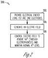
- FIG. 2is a flow chart illustrating an overview of a method for providing electrical energy to the kidney of a subject to control, through a process of electrophoresis, the levels of a first and second constituent in the kidney.
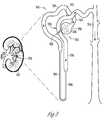
- FIG. 3is a diagram illustrating generally an example of a nephron in a kidney.
- FIG. 4is a diagram illustrating generally an example of some of the processes that take place within a nephron.
- FIG. 5is a block diagram illustrating generally an example of a monitoring circuit associated with the application of an electric field to the kidney.
- This documentdescribes, among other things, applying electric fields to a patient's kidney(s) to reduce retention of salt and water through a process of electrophoresis. Reduced salt and water retention can benefit patients suffering from fluid overload, such as those with congestive heart failure.
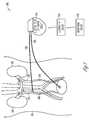
- FIG. 1is a diagram illustrating generally an example of a system 100 for applying an electric field to a subject's body 101 , and more specifically, to one or both kidneys 102 .
- a first electrode 110 and a second electrode 112have been implanted in the subject.
- at least one of the first electrode 110 or second electrode 112can be incorporated into a stent anchor placed within a vessel or tubular structure, such as a ureter.
- at least one of the first electrode 110 or second electrode 112can be incorporated into a cuff surrounding a vessel or tubular structure.
- the first electrode 110which can include a cathode, is shown implanted in the urinary bladder 108 .
- the first electrode 110can also be placed in or near a ureter 106 , a Bowman's capsule, a macula densa, a renal tubule, a collecting duct, or a renal pelvis (see FIGS. 3 and 4 ).
- the second electrode 112which can include an anode, is shown implanted in a renal vein 104 .
- the second electrode 112can be placed in or near a renal artery 105 or a peritubular capillary network (see FIGS. 3 and 4 ).
- the first electrode 110 and the second electrode 112are coupled to an electric field generator circuit 114 , which can be external, as shown, or part of an implantable device.
- the first electrodeincludes the anode and the second electrode includes the cathode.
- the electrodes 110 and 112can be coupled to the electric field generator circuit 114 via one or more leads 120 , as shown.
- the leads 120can be implantable.
- the electrodes 110 and 112can be coupled to the electric field generator circuit 114 via leadless technologies.
- the electric field generator circuit 114can generate a biphasic voltage pulse, including, for example, a first positive and a second negative phase.
- the magnitude of at least one of the first or second phasecan be between about 0.1 Volt and about 20 Volts.
- the electric field generator circuit 114can generate pulses at a repetition rate that is between about 10 minutes and about 1 microsecond.
- the electric field generator circuit 114can produce biphasic pulses in order to produce charge balance in the vicinity of the electrodes while ensuring greater net excretion of sodium and water.
- the electric field generator circuit 114is coupled to the controller circuit 116 , which can be external, as shown, or part of an implantable device.
- the controller circuit 116can communicate wirelessly with the electric field generator circuit 114 .
- the controller circuit 116can receive input information from certain implanted sensors, such as a sodium sensor, a potassium sensor, a heart sound sensor, a thoracic impedance sensor, an activity sensor, a respiration sensor, a blood pressure sensor, an electrocardiogram sensor, an oxygen saturation sensor, a blood flow sensor, a temperature sensor, or a renal conductivity sensor.
- the sensorscan be incorporated in the monitoring circuit 118 , described below.
- the sensor input informationcan be used by the controller circuit 116 to adjust at least one of a magnitude, a pulsewidth, a frequency, a duration, or a waveform associated with the electric field.
- the controller circuit 116can direct the electric field generator circuit 114 to increase the magnitude, pulsewidth, frequency, or duration of electric energy delivered to the kidney.
- the increased magnitude, pulsewidth, frequency, or duration of electric energycan, in turn, create an electrophoretic gradient causing an increase in sodium and water excretion, as described below.
- the controller circuit 116is also coupled to the monitoring circuit 118 , which can be external, as shown, or part of an implantable device.
- the monitoring circuit 118which is described further with regard to FIG. 5 , is configured to monitor the level of a first constituent in the kidney and a level of a second constituent in the kidney.
- the first constituentmay include sodium and the second constituent may include potassium, and the monitoring circuit 118 includes a sodium sensor and a potassium sensor to monitor the levels of the first and second constituents.
- the monitoring circuit 118can communicate wirelessly with the controller circuit 116 .
- Information from the monitoring circuit 118 about the levels of a first and second constituent in the kidneycan be used by the controller circuit to adjust the magnitude, pulsewidth, frequency, or duration of electric energy delivered to the kidney, such that the levels of the first and second constituents remain within specified ranges.
- FIG. 2is a flow chart illustrating an overview of a method 200 for providing electrical energy to the kidney of a subject to control, through a process of electrophoresis, the levels of a first and second constituent in the kidney.
- electrical energyis provided using a first electrode and a second electrode.
- At least one of the first electrode or the second electrodeis implantably associated with a kidney of a subject.
- the first electrodecan include a cathode and it can be used in or near at least one of a Bowman's capsule, a macula densa, a tubule, a collecting duct, a renal pelvis, a ureter, or a urinary bladder.
- the second electrodecan include an anode, and it can be used in or near a renal vein, renal artery, or a peritubular capillary network.
- Providing electrical energy using the first and second electrodescan include providing a biphasic voltage pulse. At least one of the first or second phases of the biphasic voltage pulse can have a magnitude in the range of about 0.1-20 Volts.
- providing electrical energy using the first and second electrodescan include providing pulses at a repetition rate in the range of about 1 microsecond to about 10 minutes.
- an electric fieldis generated using the first and second electrodes.
- the electric fieldis controlled such that, through a process of electrophoresis, a first constituent, such as sodium, is removed from the kidney and a second constituent, such as potassium, is maintained within normal physiological levels.
- the levels of the first and second constituentscan be monitored through an implanted or external sensing device.
- Initiating electrophoresis with the electric fieldcan further include removing water from the kidney, for example when the first constituent includes sodium. When sodium ions are removed from the kidney, water passively diffuses down its concentration gradient, out of the kidney and into the filtrate, along with sodium.
- Controlling the electric filedcan also include controlling at least one of a magnitude, a pulsewidth, a frequency, a duration, or a waveform associated with the electric field using information about at least one of the level of the first constituent or the second constituent.
- controlling the electric fieldcan include controlling at least one of a magnitude, a pulsewidth, a frequency, a duration, or a waveform associated with the electric field using information from at least one implanted sensor including an implantable heart sound sensor; an implantable impedance sensor; an implantable activity sensor; an implantable respiration sensor; an implantable blood pressure sensor; an implantable electrocardiogram sensor; an implantable oxygen saturation sensor; an implantable blood flow sensor; an implantable temperature sensor; or an implantable renal conductivity sensor.
- FIG. 3diagrammatically illustrates one of many nephrons 350 in a kidney 102 .
- the nephrons 350perform the actual filtering in the kidneys 102 .
- discussionwill now turn to the normal physiology of a nephron 350 and its associated structure.
- Each nephronconsists of a spherical filtering component, called the renal corpuscle 352 , and a tubule 354 extending from the renal corpuscle 352 .
- the renal corpuscle 352is responsible for the initial step in urine formation (i.e., the separation of a protein-free filtrate from plasma) and consists of interconnected capillary loops, called the glomerulus 356 , surrounded by a hollow capsule, known as Bowman's capsule 358 . Blood enters and leaves Bowman's capsule 358 through afferent and efferent arterioles 360 , 362 that penetrate the surface of the capsule 358 . A fluid-filled space exists within the capsule 358 , and it is into this space that fluid filters.
- the fluid filtered from the glomerulus 356 into the capsule 358is called the filtrate.
- the Bowman's capsule 358Opposite the vascular pole, the Bowman's capsule 358 has an opening that leads into the first portion of the tubule 354 .
- the filtratecontinues to flow through the various portions of the tubule (the proximal convoluted tubule 364 , the descending thin limb of Henle's loop 366 , the ascending thin limb of Henle's loop 368 , the think ascending limb of Henle's loop, the distal convoluted tubule 372 , and the collecting duct 374 ), the processes of tubular reabsorption (e.g.
- each renal calyxis continuous with the ureter 106 ( FIG. 1 ), which empties into the urinary bladder 108 ( FIG. 1 ), where urine is temporarily stored and from which it is intermittently eliminated.
- FIG. 4is a simplified diagram further illustrating some of the processes that take place in the nephron, as described in FIG. 3 .
- inorganic ionse.g. sodium
- low-molecular-weight organic solutese.g. sodium
- watere.g. water
- the remaining bloodexits the glomerulus 356 through the efferent arteriole 362 , which then subdivides into a set of peritubular capillaries 408 .
- the peritubular capillaries 408then rejoin to form veins, and ultimately the renal vein 410 , through which blood leaves the kidney.
- the portion of the blood that is filtered from the glomerulus 356 into the Bowman's capsule 358forms the filtrate, as discussed above.
- the filtrateincludes small ions, glucose, urea, amino acids, hormones, some macromolecules, and water. As discussed above with respect to FIG. 3 , many of the substances in the filtrate will later be reabsorbed in the tubule 354 - 374 . The discussion will now focus on the reabsorption of sodium and water from lumen of the tubule 354 - 374 into the peritubular capillary 408 .
- Positively charged sodium ions in the tubular lumenpassively enter the cells that form the wall of the tubule 354 - 374 (tubular cells), as the insides of tubular cells are negatively charged with respect to the lumen. After entering the tubular cells, the sodium ions are actively transported out into the interstitial fluid, and eventually reabsorbed back into the blood through the peritubular capillary 408 . The reabsorption of water from the tubule into the peritubular capillary 408 occurs via osmosis, secondary to the reabsorption of sodium.
- the resulting electric fieldcan affect the reabsorption of sodium and water through the process of electrophoresis.
- Application of an electric field to charged particles (e.g. sodium ions) dispersed in a fluidcauses the particles to migrate along their electrophoretic gradient.
- Applying the above described electric field to the kidneycan cause sodium to migrate along its electrophoretic gradient from the positively charged peritubular capillary 408 to the negatively charged ureter 106 (and adjacent tubule 354 - 374 ), counteracting the passive transport of positively charged sodium ions from the tubule 354 - 374 to the peritubular capillary 408 .
- Thiscan lead to a lesser degree of sodium (and water) reabsorption.
- a greater degree of sodium and watercan be excreted through the ureter 106 and eventually eliminated from the body.
- the application of an electric fieldcan have a diuretic effect on the kidney. This result can potentially be of great benefit to patients who are fluid overloaded, such as heart failure patients.
- One problem that may develop with this approach, as with loop diuretics,is increased excretion of potassium. Because potassium ions are also positively charged (like sodium ions), applying an electric filed in the manner described above can result in decreased reabsorption of potassium. This can be dangerous because low potassium levels, or hypokalemia, can result in cardiac arrhythmias, severe muscle weakness or paralysis, rhabdomyolysis, and renal dysfunction.
- the application of electric fields to the kidneycan be accompanied by a potassium monitoring and a feedback control mechanism, as described below, such that hypokalemia is avoided.
- this therapycan be used with increased potassium intake (through pills), or other potassium sparing diuretics.
- FIG. 5is a block diagram illustrating an example of a monitoring circuit 118 .
- the monitoring circuit 118which can be an implanted or external device, can include chemical sensors 504 and 506 for constituent 1 and constituent 2 , respectively.
- the chemical sensorscan include among other things, a sodium sensor, a potassium sensor, a hydrogen ion sensor, and a bicarbonate sensor.
- An approach to monitoring bodily fluids with chemical sensorsis described in International Patent Application PCT/US2007/068954, entitled “Implantable Medical Device with Chemical Sensor and Related Methods,” which is incorporated herein by reference in its entirety.
- Chemical sensors 504 and 506can detect a physiological level or concentration of a constituent, such as an ion, in a bodily fluid of a subject (e.g.
- Chemical sensors 504 and 506can each include an optical excitation assembly 508 , 510 ; a sensing element 512 , 514 ; and an optical detection assembly 516 , 518 . Furthermore, chemical sensors 504 and 506 can be communicatively linked through wired or wireless technologies.
- the monitoring circuit 118is coupled to the controller circuit 116 , as shown in FIG. 1 .
- these valuescan be communicated to the controller circuit 116 .
- the controller circuit 116can use these values to determine whether a given level of constituent 1 or constituent 2 is within a predetermined range. If the level of the first constituent is above or below a predetermined range, the controller circuit 116 can modulate the electric field by increasing or decreasing a magnitude, pulsewidth, frequency, duration, or waveform associated with the electric field.
- the controller circuit 116can modulate the electric field by increasing or decreasing a magnitude, pulsewidth, frequency, duration, or waveform associated with the electric field. For example, if chemical sensor 504 detects an abnormally high level of sodium, this information can be communicated to the controller circuit 116 , which can control the electric field by increasing the strength, duration, or frequency, for example, thereby affecting the electrophoretic gradient for sodium, causing decreased reabsorption, increased excretion, and ultimately a decrease in the level of sodium detected by chemical sensor 504 . In another example, chemical sensor 506 can detect an abnormally low level of potassium.
- This informationcan trigger the controller circuit to decrease the strength, duration, or frequency of the electric field, for example, thereby affecting the electrophoretic gradient for potassium, causing increased reabsorption and decreased excretion of potassium (and sodium), and ultimately leading to an increase in the level of potassium detected by chemical sensor 504 . From these examples, it is apparent that the electric field must be tightly controlled in such a manner as to effectuate the removal of sodium while at the same time maintaining a normal physiological level of potassium.
- the monitoring circuit 118can be used to help achieve the necessary control of the electric field.
- sodium and “potassium” levelsfor illustrative clarity.
- the terms “sodium” and “salt,” as used in this document,can be used interchangeably to refer to “sodium ions” without departing from the scope of the described systems or methods.
- the terms “a” or “an”are used, as is common in patent documents, to include one or more than one, independent of any other instances or usages of “at least one” or “one or more.”
- the term “or”is used to refer to a nonexclusive or, such that “A or B” includes “A but not B,” “B but not A,” and “A and B,” unless otherwise indicated.
- Method examples described hereincan be machine or computer-implemented at least in part. Some examples can include a computer-readable medium or machine-readable medium encoded with instructions operable to configure an electronic device to perform methods as described in the above examples.
- An implementation of such methodscan include code, such as microcode, assembly language code, a higher-level language code, or the like. Such code can include computer readable instructions for performing various methods. The code may form portions of computer program products. Further, the code may be tangibly stored on one or more volatile or non-volatile computer-readable media during execution or at other times.
- These computer-readable mediamay include, but are not limited to, hard disks, removable magnetic disks, removable optical disks (e.g., compact disks and digital video disks), magnetic cassettes, memory cards or sticks, random access memories (RAM's), read only memories (ROM's), and the like.
Landscapes
- Health & Medical Sciences (AREA)
- Animal Behavior & Ethology (AREA)
- Biomedical Technology (AREA)
- Nuclear Medicine, Radiotherapy & Molecular Imaging (AREA)
- Radiology & Medical Imaging (AREA)
- Life Sciences & Earth Sciences (AREA)
- Engineering & Computer Science (AREA)
- General Health & Medical Sciences (AREA)
- Public Health (AREA)
- Veterinary Medicine (AREA)
- Electrotherapy Devices (AREA)
- Medicines That Contain Protein Lipid Enzymes And Other Medicines (AREA)
- Measuring And Recording Apparatus For Diagnosis (AREA)
- Measurement Of The Respiration, Hearing Ability, Form, And Blood Characteristics Of Living Organisms (AREA)
Abstract
Description
Claims (22)
Priority Applications (1)
| Application Number | Priority Date | Filing Date | Title |
|---|---|---|---|
| US12/683,553US8457761B2 (en) | 2009-01-14 | 2010-01-07 | System and method for promoting diuresis and natriuresis by the application of electric fields to the kidney |
Applications Claiming Priority (2)
| Application Number | Priority Date | Filing Date | Title |
|---|---|---|---|
| US14450009P | 2009-01-14 | 2009-01-14 | |
| US12/683,553US8457761B2 (en) | 2009-01-14 | 2010-01-07 | System and method for promoting diuresis and natriuresis by the application of electric fields to the kidney |
Publications (2)
| Publication Number | Publication Date |
|---|---|
| US20100179620A1 US20100179620A1 (en) | 2010-07-15 |
| US8457761B2true US8457761B2 (en) | 2013-06-04 |
Family
ID=41719398
Family Applications (1)
| Application Number | Title | Priority Date | Filing Date |
|---|---|---|---|
| US12/683,553Expired - Fee RelatedUS8457761B2 (en) | 2009-01-14 | 2010-01-07 | System and method for promoting diuresis and natriuresis by the application of electric fields to the kidney |
Country Status (6)
| Country | Link |
|---|---|
| US (1) | US8457761B2 (en) |
| EP (1) | EP2389223A1 (en) |
| JP (1) | JP5199487B2 (en) |
| CN (1) | CN102281916B (en) |
| AU (1) | AU2010204957B2 (en) |
| WO (1) | WO2010083086A1 (en) |
Cited By (101)
| Publication number | Priority date | Publication date | Assignee | Title |
|---|---|---|---|---|
| US9526909B2 (en) | 2014-08-28 | 2016-12-27 | Cardiac Pacemakers, Inc. | Medical device with triggered blanking period |
| US9592391B2 (en) | 2014-01-10 | 2017-03-14 | Cardiac Pacemakers, Inc. | Systems and methods for detecting cardiac arrhythmias |
| US9616221B2 (en) | 2015-07-08 | 2017-04-11 | Rainbow Medical Ltd. | Electrical treatment of Alzheimer's disease |
| US9669230B2 (en) | 2015-02-06 | 2017-06-06 | Cardiac Pacemakers, Inc. | Systems and methods for treating cardiac arrhythmias |
| US9694189B2 (en) | 2014-08-06 | 2017-07-04 | Cardiac Pacemakers, Inc. | Method and apparatus for communicating between medical devices |
| US9724515B2 (en) | 2015-10-29 | 2017-08-08 | Rainbow Medical Ltd. | Electrical substance clearance from the brain for treatment of Alzheimer's disease |
| US9731122B2 (en) | 2013-04-29 | 2017-08-15 | Rainbow Medical Ltd. | Electroosmotic tissue treatment |
| US9757570B2 (en) | 2014-08-06 | 2017-09-12 | Cardiac Pacemakers, Inc. | Communications in a medical device system |
| US9770591B2 (en) | 2015-12-29 | 2017-09-26 | Rainbow Medical Ltd. | Disc therapy |
| US9808631B2 (en) | 2014-08-06 | 2017-11-07 | Cardiac Pacemakers, Inc. | Communication between a plurality of medical devices using time delays between communication pulses to distinguish between symbols |
| US9853743B2 (en) | 2015-08-20 | 2017-12-26 | Cardiac Pacemakers, Inc. | Systems and methods for communication between medical devices |
| US9950156B2 (en) | 2016-09-13 | 2018-04-24 | Rainbow Medical Ltd. | Disc therapy |
| US9956414B2 (en) | 2015-08-27 | 2018-05-01 | Cardiac Pacemakers, Inc. | Temporal configuration of a motion sensor in an implantable medical device |
| US9968787B2 (en) | 2015-08-27 | 2018-05-15 | Cardiac Pacemakers, Inc. | Spatial configuration of a motion sensor in an implantable medical device |
| US10029107B1 (en) | 2017-01-26 | 2018-07-24 | Cardiac Pacemakers, Inc. | Leadless device with overmolded components |
| US10050700B2 (en) | 2015-03-18 | 2018-08-14 | Cardiac Pacemakers, Inc. | Communications in a medical device system with temporal optimization |
| US10046167B2 (en) | 2015-02-09 | 2018-08-14 | Cardiac Pacemakers, Inc. | Implantable medical device with radiopaque ID tag |
| US10065041B2 (en) | 2015-10-08 | 2018-09-04 | Cardiac Pacemakers, Inc. | Devices and methods for adjusting pacing rates in an implantable medical device |
| US10092760B2 (en) | 2015-09-11 | 2018-10-09 | Cardiac Pacemakers, Inc. | Arrhythmia detection and confirmation |
| US10137305B2 (en) | 2015-08-28 | 2018-11-27 | Cardiac Pacemakers, Inc. | Systems and methods for behaviorally responsive signal detection and therapy delivery |
| US10159842B2 (en) | 2015-08-28 | 2018-12-25 | Cardiac Pacemakers, Inc. | System and method for detecting tamponade |
| US10183170B2 (en) | 2015-12-17 | 2019-01-22 | Cardiac Pacemakers, Inc. | Conducted communication in a medical device system |
| US10213610B2 (en) | 2015-03-18 | 2019-02-26 | Cardiac Pacemakers, Inc. | Communications in a medical device system with link quality assessment |
| US10220213B2 (en) | 2015-02-06 | 2019-03-05 | Cardiac Pacemakers, Inc. | Systems and methods for safe delivery of electrical stimulation therapy |
| US10226631B2 (en) | 2015-08-28 | 2019-03-12 | Cardiac Pacemakers, Inc. | Systems and methods for infarct detection |
| US10328272B2 (en) | 2016-05-10 | 2019-06-25 | Cardiac Pacemakers, Inc. | Retrievability for implantable medical devices |
| US10350423B2 (en) | 2016-02-04 | 2019-07-16 | Cardiac Pacemakers, Inc. | Delivery system with force sensor for leadless cardiac device |
| US10357159B2 (en) | 2015-08-20 | 2019-07-23 | Cardiac Pacemakers, Inc | Systems and methods for communication between medical devices |
| US10391319B2 (en) | 2016-08-19 | 2019-08-27 | Cardiac Pacemakers, Inc. | Trans septal implantable medical device |
| US10413733B2 (en) | 2016-10-27 | 2019-09-17 | Cardiac Pacemakers, Inc. | Implantable medical device with gyroscope |
| US10426962B2 (en) | 2016-07-07 | 2019-10-01 | Cardiac Pacemakers, Inc. | Leadless pacemaker using pressure measurements for pacing capture verification |
| US10434317B2 (en) | 2016-10-31 | 2019-10-08 | Cardiac Pacemakers, Inc. | Systems and methods for activity level pacing |
| US10434314B2 (en) | 2016-10-27 | 2019-10-08 | Cardiac Pacemakers, Inc. | Use of a separate device in managing the pace pulse energy of a cardiac pacemaker |
| US10463305B2 (en) | 2016-10-27 | 2019-11-05 | Cardiac Pacemakers, Inc. | Multi-device cardiac resynchronization therapy with timing enhancements |
| US10512784B2 (en) | 2016-06-27 | 2019-12-24 | Cardiac Pacemakers, Inc. | Cardiac therapy system using subcutaneously sensed P-waves for resynchronization pacing management |
| US10518085B2 (en) | 2015-12-29 | 2019-12-31 | Rainbow Medical Ltd. | Disc therapy |
| US10561330B2 (en) | 2016-10-27 | 2020-02-18 | Cardiac Pacemakers, Inc. | Implantable medical device having a sense channel with performance adjustment |
| US10569086B2 (en) | 2017-01-11 | 2020-02-25 | Rainbow Medical Ltd. | Electrical microglial cell activation |
| US10583303B2 (en) | 2016-01-19 | 2020-03-10 | Cardiac Pacemakers, Inc. | Devices and methods for wirelessly recharging a rechargeable battery of an implantable medical device |
| US10583301B2 (en) | 2016-11-08 | 2020-03-10 | Cardiac Pacemakers, Inc. | Implantable medical device for atrial deployment |
| US10617874B2 (en) | 2016-10-31 | 2020-04-14 | Cardiac Pacemakers, Inc. | Systems and methods for activity level pacing |
| US10632313B2 (en) | 2016-11-09 | 2020-04-28 | Cardiac Pacemakers, Inc. | Systems, devices, and methods for setting cardiac pacing pulse parameters for a cardiac pacing device |
| US10639486B2 (en) | 2016-11-21 | 2020-05-05 | Cardiac Pacemakers, Inc. | Implantable medical device with recharge coil |
| US10668294B2 (en) | 2016-05-10 | 2020-06-02 | Cardiac Pacemakers, Inc. | Leadless cardiac pacemaker configured for over the wire delivery |
| US10688304B2 (en) | 2016-07-20 | 2020-06-23 | Cardiac Pacemakers, Inc. | Method and system for utilizing an atrial contraction timing fiducial in a leadless cardiac pacemaker system |
| US10722720B2 (en) | 2014-01-10 | 2020-07-28 | Cardiac Pacemakers, Inc. | Methods and systems for improved communication between medical devices |
| US10737102B2 (en) | 2017-01-26 | 2020-08-11 | Cardiac Pacemakers, Inc. | Leadless implantable device with detachable fixation |
| US10758724B2 (en) | 2016-10-27 | 2020-09-01 | Cardiac Pacemakers, Inc. | Implantable medical device delivery system with integrated sensor |
| US10758722B2 (en) | 2017-05-03 | 2020-09-01 | Rainbow Medical Ltd. | Electrical treatment of Parkinson's disease |
| US10758737B2 (en) | 2016-09-21 | 2020-09-01 | Cardiac Pacemakers, Inc. | Using sensor data from an intracardially implanted medical device to influence operation of an extracardially implantable cardioverter |
| US10765871B2 (en) | 2016-10-27 | 2020-09-08 | Cardiac Pacemakers, Inc. | Implantable medical device with pressure sensor |
| US10780278B2 (en) | 2016-08-24 | 2020-09-22 | Cardiac Pacemakers, Inc. | Integrated multi-device cardiac resynchronization therapy using P-wave to pace timing |
| US10821288B2 (en) | 2017-04-03 | 2020-11-03 | Cardiac Pacemakers, Inc. | Cardiac pacemaker with pacing pulse energy adjustment based on sensed heart rate |
| US10835753B2 (en) | 2017-01-26 | 2020-11-17 | Cardiac Pacemakers, Inc. | Intra-body device communication with redundant message transmission |
| US10849545B2 (en) | 2016-06-02 | 2020-12-01 | Cardiac Pacemakers, Inc. | Acute kidney injury detection system and methods |
| US10870008B2 (en) | 2016-08-24 | 2020-12-22 | Cardiac Pacemakers, Inc. | Cardiac resynchronization using fusion promotion for timing management |
| US10874861B2 (en) | 2018-01-04 | 2020-12-29 | Cardiac Pacemakers, Inc. | Dual chamber pacing without beat-to-beat communication |
| US10881858B1 (en) | 2019-09-18 | 2021-01-05 | Rainbow Medical Ltd. | Electrical substance clearance from the brain |
| US10881863B2 (en) | 2016-11-21 | 2021-01-05 | Cardiac Pacemakers, Inc. | Leadless cardiac pacemaker with multimode communication |
| US10881869B2 (en) | 2016-11-21 | 2021-01-05 | Cardiac Pacemakers, Inc. | Wireless re-charge of an implantable medical device |
| US10894163B2 (en) | 2016-11-21 | 2021-01-19 | Cardiac Pacemakers, Inc. | LCP based predictive timing for cardiac resynchronization |
| US10898716B2 (en) | 2015-10-29 | 2021-01-26 | Rainbow Medical Ltd. | Electrical substance clearance from the brain |
| US10905886B2 (en) | 2015-12-28 | 2021-02-02 | Cardiac Pacemakers, Inc. | Implantable medical device for deployment across the atrioventricular septum |
| US10905889B2 (en) | 2016-09-21 | 2021-02-02 | Cardiac Pacemakers, Inc. | Leadless stimulation device with a housing that houses internal components of the leadless stimulation device and functions as the battery case and a terminal of an internal battery |
| US10905872B2 (en) | 2017-04-03 | 2021-02-02 | Cardiac Pacemakers, Inc. | Implantable medical device with a movable electrode biased toward an extended position |
| US10918875B2 (en) | 2017-08-18 | 2021-02-16 | Cardiac Pacemakers, Inc. | Implantable medical device with a flux concentrator and a receiving coil disposed about the flux concentrator |
| US10994145B2 (en) | 2016-09-21 | 2021-05-04 | Cardiac Pacemakers, Inc. | Implantable cardiac monitor |
| US11052258B2 (en) | 2017-12-01 | 2021-07-06 | Cardiac Pacemakers, Inc. | Methods and systems for detecting atrial contraction timing fiducials within a search window from a ventricularly implanted leadless cardiac pacemaker |
| US11058880B2 (en) | 2018-03-23 | 2021-07-13 | Medtronic, Inc. | VFA cardiac therapy for tachycardia |
| US11065459B2 (en) | 2017-08-18 | 2021-07-20 | Cardiac Pacemakers, Inc. | Implantable medical device with pressure sensor |
| US11071870B2 (en) | 2017-12-01 | 2021-07-27 | Cardiac Pacemakers, Inc. | Methods and systems for detecting atrial contraction timing fiducials and determining a cardiac interval from a ventricularly implanted leadless cardiac pacemaker |
| US11116988B2 (en) | 2016-03-31 | 2021-09-14 | Cardiac Pacemakers, Inc. | Implantable medical device with rechargeable battery |
| US11123197B2 (en) | 2019-09-03 | 2021-09-21 | Rainbow Medical Ltd. | Hydropneumatic artificial intervertebral disc |
| US11147979B2 (en) | 2016-11-21 | 2021-10-19 | Cardiac Pacemakers, Inc. | Implantable medical device with a magnetically permeable housing and an inductive coil disposed about the housing |
| US11185703B2 (en) | 2017-11-07 | 2021-11-30 | Cardiac Pacemakers, Inc. | Leadless cardiac pacemaker for bundle of his pacing |
| US11202905B2 (en) | 2018-03-14 | 2021-12-21 | Rainbow Medical Ltd. | Electrical substance clearance from the brain |
| US11207532B2 (en) | 2017-01-04 | 2021-12-28 | Cardiac Pacemakers, Inc. | Dynamic sensing updates using postural input in a multiple device cardiac rhythm management system |
| US11207527B2 (en) | 2016-07-06 | 2021-12-28 | Cardiac Pacemakers, Inc. | Method and system for determining an atrial contraction timing fiducial in a leadless cardiac pacemaker system |
| US11213676B2 (en) | 2019-04-01 | 2022-01-04 | Medtronic, Inc. | Delivery systems for VfA cardiac therapy |
| US11235159B2 (en) | 2018-03-23 | 2022-02-01 | Medtronic, Inc. | VFA cardiac resynchronization therapy |
| US11235163B2 (en) | 2017-09-20 | 2022-02-01 | Cardiac Pacemakers, Inc. | Implantable medical device with multiple modes of operation |
| US11235161B2 (en) | 2018-09-26 | 2022-02-01 | Medtronic, Inc. | Capture in ventricle-from-atrium cardiac therapy |
| US11260216B2 (en) | 2017-12-01 | 2022-03-01 | Cardiac Pacemakers, Inc. | Methods and systems for detecting atrial contraction timing fiducials during ventricular filling from a ventricularly implanted leadless cardiac pacemaker |
| US11285326B2 (en) | 2015-03-04 | 2022-03-29 | Cardiac Pacemakers, Inc. | Systems and methods for treating cardiac arrhythmias |
| US11298530B1 (en) | 2021-05-03 | 2022-04-12 | Discure Technologies Ltd. | Synergistic therapies for intervertebral disc degeneration |
| US11305127B2 (en) | 2019-08-26 | 2022-04-19 | Medtronic Inc. | VfA delivery and implant region detection |
| US11344721B1 (en) | 2021-08-16 | 2022-05-31 | Rainbow Medical Ltd. | Cartilage treatment |
| US11400296B2 (en) | 2018-03-23 | 2022-08-02 | Medtronic, Inc. | AV synchronous VfA cardiac therapy |
| US11413455B1 (en) | 2022-02-08 | 2022-08-16 | Rainbow Medical Ltd. | Electrical treatment of Alzheimer's disease |
| US11484706B2 (en) | 2015-12-29 | 2022-11-01 | Discure Technologies Ltd | Disc therapy |
| US11529523B2 (en) | 2018-01-04 | 2022-12-20 | Cardiac Pacemakers, Inc. | Handheld bridge device for providing a communication bridge between an implanted medical device and a smartphone |
| US11679265B2 (en) | 2019-02-14 | 2023-06-20 | Medtronic, Inc. | Lead-in-lead systems and methods for cardiac therapy |
| US11697025B2 (en) | 2019-03-29 | 2023-07-11 | Medtronic, Inc. | Cardiac conduction system capture |
| US11712188B2 (en) | 2019-05-07 | 2023-08-01 | Medtronic, Inc. | Posterior left bundle branch engagement |
| US11813466B2 (en) | 2020-01-27 | 2023-11-14 | Medtronic, Inc. | Atrioventricular nodal stimulation |
| US11813464B2 (en) | 2020-07-31 | 2023-11-14 | Medtronic, Inc. | Cardiac conduction system evaluation |
| US11813463B2 (en) | 2017-12-01 | 2023-11-14 | Cardiac Pacemakers, Inc. | Leadless cardiac pacemaker with reversionary behavior |
| US11911168B2 (en) | 2020-04-03 | 2024-02-27 | Medtronic, Inc. | Cardiac conduction system therapy benefit determination |
| US11951313B2 (en) | 2018-11-17 | 2024-04-09 | Medtronic, Inc. | VFA delivery systems and methods |
| US12208267B1 (en) | 2024-04-19 | 2025-01-28 | Yossi Gross | Blood flow enhancement therapy system |
| US12296177B2 (en) | 2018-12-21 | 2025-05-13 | Medtronic, Inc. | Delivery systems and methods for left ventricular pacing |
Families Citing this family (6)
| Publication number | Priority date | Publication date | Assignee | Title |
|---|---|---|---|---|
| US20080119907A1 (en)* | 2006-11-22 | 2008-05-22 | Cardiac Pacemakers, Inc. | Renal function modulation via application of electrical energy stimulation |
| US8457761B2 (en) | 2009-01-14 | 2013-06-04 | Cardiac Pacemakers, Inc. | System and method for promoting diuresis and natriuresis by the application of electric fields to the kidney |
| US8359093B2 (en)* | 2009-05-07 | 2013-01-22 | Cardiac Pacemakers, Inc. | Application of electric fields to the lung as therapy for pulmonary edema |
| US20120290024A1 (en)* | 2011-05-11 | 2012-11-15 | St. Jude Medical, Inc. | Transvenous renal nerve modulation for treatment of hypertension, cardiovascular disorders, and chronic renal diseases |
| CN105769380B (en)* | 2016-05-30 | 2017-09-22 | 周建 | Fundus of bladder support arm and method for implantation in pelvis |
| WO2025038973A1 (en)* | 2023-08-16 | 2025-02-20 | Nidus Holdings, Llc | Implantable energy devices and methods |
Citations (28)
| Publication number | Priority date | Publication date | Assignee | Title |
|---|---|---|---|---|
| US5529574A (en) | 1992-08-21 | 1996-06-25 | Frackelton; James P. | Method and apparatus for treatment of the prostate |
| US5779661A (en) | 1995-12-11 | 1998-07-14 | Physion, S.R.L. | Method of treating dysfunctional bladder syndromes by electromotive drug administration |
| WO2000074775A1 (en) | 1999-06-03 | 2000-12-14 | Martil Instruments B.V. | Method, device and catheter for in vivo determining blood properties such as blood viscosity |
| WO2001052931A1 (en) | 2000-01-21 | 2001-07-26 | Impulse Dynamics Nv | Blood flow controller |
| US6381493B1 (en) | 1999-03-29 | 2002-04-30 | Medtronic, Inc. | Ischemia detection during non-standard cardiac excitation patterns |
| US6424864B1 (en) | 1997-11-28 | 2002-07-23 | Masayuki Matsuura | Method and apparatus for wave therapy |
| US20030216792A1 (en) | 2002-04-08 | 2003-11-20 | Levin Howard R. | Renal nerve stimulation method and apparatus for treatment of patients |
| US20040220621A1 (en) | 2003-04-30 | 2004-11-04 | Xiaohong Zhou | Methods and apparatus for the regulation of hormone release |
| US20050021092A1 (en) | 2003-06-09 | 2005-01-27 | Yun Anthony Joonkyoo | Treatment of conditions through modulation of the autonomic nervous system |
| US20050187581A1 (en) | 2000-12-18 | 2005-08-25 | Hakuju Institute For Health Science, Co., Ltd. | Methods of treating disorders with electric fields |
| US20050192638A1 (en) | 2002-04-08 | 2005-09-01 | Mark Gelfand | Methods and devices for renal nerve blocking |
| US6941172B2 (en) | 2002-11-18 | 2005-09-06 | Zvi Nachum | Method and device for restoring kidney function using electromagnetic stimulation |
| US20050288730A1 (en) | 2002-04-08 | 2005-12-29 | Mark Deem | Methods and apparatus for renal neuromodulation |
| US20060041277A1 (en) | 2002-04-08 | 2006-02-23 | Mark Deem | Methods and apparatus for renal neuromodulation |
| US20060142801A1 (en) | 2002-04-08 | 2006-06-29 | Ardian, Inc. | Methods and apparatus for intravascularly-induced neuromodulation |
| WO2006090397A2 (en) | 2005-02-28 | 2006-08-31 | A.I. Medical Semiconductor | Adaptive cardiac resynchronization therapy and vagal stimulation |
| US20060206150A1 (en) | 2002-04-08 | 2006-09-14 | Ardian, Inc. | Methods and apparatus for treating acute myocardial infarction |
| US20060235474A1 (en) | 2002-04-08 | 2006-10-19 | Ardian, Inc. | Methods and apparatus for multi-vessel renal neuromodulation |
| US20060265015A1 (en) | 2002-04-08 | 2006-11-23 | Ardian, Inc. | Methods and apparatus for monopolar renal neuromodulation |
| US20060265014A1 (en) | 2002-04-08 | 2006-11-23 | Ardian, Inc. | Methods and apparatus for bilateral renal neuromodulation |
| US20060276852A1 (en) | 2002-04-08 | 2006-12-07 | Ardian, Inc. | Methods and apparatus for treating hypertension |
| WO2007019491A2 (en) | 2005-08-08 | 2007-02-15 | Katims Jefferson J | Method and apparatus for producing therapeutic and diagnostic stimulation |
| US20070066957A1 (en) | 2004-11-02 | 2007-03-22 | Ardian, Inc. | Methods and apparatus for inducing controlled renal neuromodulation |
| US20070083239A1 (en) | 2005-09-23 | 2007-04-12 | Denise Demarais | Methods and apparatus for inducing, monitoring and controlling renal neuromodulation |
| US20070129761A1 (en) | 2002-04-08 | 2007-06-07 | Ardian, Inc. | Methods for treating heart arrhythmia |
| US20070203549A1 (en) | 2005-12-29 | 2007-08-30 | Ardian, Inc. | Methods and apparatus for pulsed electric field neuromodulation via an intra-to-extravascular approach |
| US20080119907A1 (en)* | 2006-11-22 | 2008-05-22 | Cardiac Pacemakers, Inc. | Renal function modulation via application of electrical energy stimulation |
| WO2010083086A1 (en) | 2009-01-14 | 2010-07-22 | Cardiac Pacemakers, Inc. | Promoting diuresis and natriuresis by applying electric field |
Family Cites Families (2)
| Publication number | Priority date | Publication date | Assignee | Title |
|---|---|---|---|---|
| US5389069A (en)* | 1988-01-21 | 1995-02-14 | Massachusetts Institute Of Technology | Method and apparatus for in vivo electroporation of remote cells and tissue |
| CN1279872C (en)* | 2003-11-05 | 2006-10-18 | 北京爱思泰克科技开发有限责任公司 | Intracorpoval urinary catheter for online monitoring sodium in urea |
- 2010
- 2010-01-07USUS12/683,553patent/US8457761B2/ennot_activeExpired - Fee Related
- 2010-01-07EPEP10700615Apatent/EP2389223A1/ennot_activeCeased
- 2010-01-07AUAU2010204957Apatent/AU2010204957B2/ennot_activeCeased
- 2010-01-07JPJP2011546281Apatent/JP5199487B2/ennot_activeExpired - Fee Related
- 2010-01-07WOPCT/US2010/020320patent/WO2010083086A1/enactiveApplication Filing
- 2010-01-07CNCN201080004520.XApatent/CN102281916B/ennot_activeExpired - Fee Related
Patent Citations (37)
| Publication number | Priority date | Publication date | Assignee | Title |
|---|---|---|---|---|
| US5529574A (en) | 1992-08-21 | 1996-06-25 | Frackelton; James P. | Method and apparatus for treatment of the prostate |
| US5779661A (en) | 1995-12-11 | 1998-07-14 | Physion, S.R.L. | Method of treating dysfunctional bladder syndromes by electromotive drug administration |
| US6424864B1 (en) | 1997-11-28 | 2002-07-23 | Masayuki Matsuura | Method and apparatus for wave therapy |
| US6381493B1 (en) | 1999-03-29 | 2002-04-30 | Medtronic, Inc. | Ischemia detection during non-standard cardiac excitation patterns |
| WO2000074775A1 (en) | 1999-06-03 | 2000-12-14 | Martil Instruments B.V. | Method, device and catheter for in vivo determining blood properties such as blood viscosity |
| WO2001052931A1 (en) | 2000-01-21 | 2001-07-26 | Impulse Dynamics Nv | Blood flow controller |
| US20050187581A1 (en) | 2000-12-18 | 2005-08-25 | Hakuju Institute For Health Science, Co., Ltd. | Methods of treating disorders with electric fields |
| US20060041277A1 (en) | 2002-04-08 | 2006-02-23 | Mark Deem | Methods and apparatus for renal neuromodulation |
| US20060212076A1 (en) | 2002-04-08 | 2006-09-21 | Ardian, Inc. | Methods and apparatus for treating end-stage renal disease |
| US20070265687A1 (en) | 2002-04-08 | 2007-11-15 | Ardian, Inc. | Apparatuses for renal neuromodulation |
| US20050192638A1 (en) | 2002-04-08 | 2005-09-01 | Mark Gelfand | Methods and devices for renal nerve blocking |
| US20070129761A1 (en) | 2002-04-08 | 2007-06-07 | Ardian, Inc. | Methods for treating heart arrhythmia |
| US20050228460A1 (en) | 2002-04-08 | 2005-10-13 | Levin Howard R | Renal nerve stimulation method and apparatus for treatment of patients |
| US20050228459A1 (en) | 2002-04-08 | 2005-10-13 | Levin Howard R | Renal nerve stimulation method and apparatus for treatment of patients |
| US20050234523A1 (en) | 2002-04-08 | 2005-10-20 | Levin Howard R | Renal nerve stimulation method and apparatus for treatment of patients |
| US6978174B2 (en) | 2002-04-08 | 2005-12-20 | Ardian, Inc. | Methods and devices for renal nerve blocking |
| US20050288730A1 (en) | 2002-04-08 | 2005-12-29 | Mark Deem | Methods and apparatus for renal neuromodulation |
| US20060025821A1 (en) | 2002-04-08 | 2006-02-02 | Mark Gelfand | Methods and devices for renal nerve blocking |
| US20030216792A1 (en) | 2002-04-08 | 2003-11-20 | Levin Howard R. | Renal nerve stimulation method and apparatus for treatment of patients |
| US20060142801A1 (en) | 2002-04-08 | 2006-06-29 | Ardian, Inc. | Methods and apparatus for intravascularly-induced neuromodulation |
| US20060276852A1 (en) | 2002-04-08 | 2006-12-07 | Ardian, Inc. | Methods and apparatus for treating hypertension |
| US20060206150A1 (en) | 2002-04-08 | 2006-09-14 | Ardian, Inc. | Methods and apparatus for treating acute myocardial infarction |
| US20060265014A1 (en) | 2002-04-08 | 2006-11-23 | Ardian, Inc. | Methods and apparatus for bilateral renal neuromodulation |
| US20060212078A1 (en) | 2002-04-08 | 2006-09-21 | Ardian, Inc. | Methods and apparatus for treating congestive heart failure |
| US20060235474A1 (en) | 2002-04-08 | 2006-10-19 | Ardian, Inc. | Methods and apparatus for multi-vessel renal neuromodulation |
| US20060265015A1 (en) | 2002-04-08 | 2006-11-23 | Ardian, Inc. | Methods and apparatus for monopolar renal neuromodulation |
| US6941172B2 (en) | 2002-11-18 | 2005-09-06 | Zvi Nachum | Method and device for restoring kidney function using electromagnetic stimulation |
| US20040220621A1 (en) | 2003-04-30 | 2004-11-04 | Xiaohong Zhou | Methods and apparatus for the regulation of hormone release |
| US20050021092A1 (en) | 2003-06-09 | 2005-01-27 | Yun Anthony Joonkyoo | Treatment of conditions through modulation of the autonomic nervous system |
| US20070066957A1 (en) | 2004-11-02 | 2007-03-22 | Ardian, Inc. | Methods and apparatus for inducing controlled renal neuromodulation |
| WO2006090397A2 (en) | 2005-02-28 | 2006-08-31 | A.I. Medical Semiconductor | Adaptive cardiac resynchronization therapy and vagal stimulation |
| WO2007019491A2 (en) | 2005-08-08 | 2007-02-15 | Katims Jefferson J | Method and apparatus for producing therapeutic and diagnostic stimulation |
| US20070083239A1 (en) | 2005-09-23 | 2007-04-12 | Denise Demarais | Methods and apparatus for inducing, monitoring and controlling renal neuromodulation |
| US20070203549A1 (en) | 2005-12-29 | 2007-08-30 | Ardian, Inc. | Methods and apparatus for pulsed electric field neuromodulation via an intra-to-extravascular approach |
| US20080119907A1 (en)* | 2006-11-22 | 2008-05-22 | Cardiac Pacemakers, Inc. | Renal function modulation via application of electrical energy stimulation |
| WO2008066732A1 (en) | 2006-11-22 | 2008-06-05 | Cardiac Pacemakers, Inc. | Renal function modulation via electrical energy stimulation |
| WO2010083086A1 (en) | 2009-01-14 | 2010-07-22 | Cardiac Pacemakers, Inc. | Promoting diuresis and natriuresis by applying electric field |
Non-Patent Citations (43)
Cited By (134)
| Publication number | Priority date | Publication date | Assignee | Title |
|---|---|---|---|---|
| US9731122B2 (en) | 2013-04-29 | 2017-08-15 | Rainbow Medical Ltd. | Electroosmotic tissue treatment |
| US12233260B2 (en) | 2013-04-29 | 2025-02-25 | Discure Technologies Ltd. | Electroosmotic tissue treatment |
| US10905875B2 (en) | 2013-04-29 | 2021-02-02 | Rainbow Medical Ltd. | Electrical treatment of hydrocephalus |
| US9592391B2 (en) | 2014-01-10 | 2017-03-14 | Cardiac Pacemakers, Inc. | Systems and methods for detecting cardiac arrhythmias |
| US10722720B2 (en) | 2014-01-10 | 2020-07-28 | Cardiac Pacemakers, Inc. | Methods and systems for improved communication between medical devices |
| US10912943B2 (en) | 2014-08-06 | 2021-02-09 | Cardiac Pacemakers, Inc. | Communications between a plurality of medical devices using time delays between communication pulses between symbols |
| US9757570B2 (en) | 2014-08-06 | 2017-09-12 | Cardiac Pacemakers, Inc. | Communications in a medical device system |
| US9808631B2 (en) | 2014-08-06 | 2017-11-07 | Cardiac Pacemakers, Inc. | Communication between a plurality of medical devices using time delays between communication pulses to distinguish between symbols |
| US9694189B2 (en) | 2014-08-06 | 2017-07-04 | Cardiac Pacemakers, Inc. | Method and apparatus for communicating between medical devices |
| US9526909B2 (en) | 2014-08-28 | 2016-12-27 | Cardiac Pacemakers, Inc. | Medical device with triggered blanking period |
| US11224751B2 (en) | 2015-02-06 | 2022-01-18 | Cardiac Pacemakers, Inc. | Systems and methods for safe delivery of electrical stimulation therapy |
| US11020595B2 (en) | 2015-02-06 | 2021-06-01 | Cardiac Pacemakers, Inc. | Systems and methods for treating cardiac arrhythmias |
| US10220213B2 (en) | 2015-02-06 | 2019-03-05 | Cardiac Pacemakers, Inc. | Systems and methods for safe delivery of electrical stimulation therapy |
| US10238882B2 (en) | 2015-02-06 | 2019-03-26 | Cardiac Pacemakers | Systems and methods for treating cardiac arrhythmias |
| US9669230B2 (en) | 2015-02-06 | 2017-06-06 | Cardiac Pacemakers, Inc. | Systems and methods for treating cardiac arrhythmias |
| US11020600B2 (en) | 2015-02-09 | 2021-06-01 | Cardiac Pacemakers, Inc. | Implantable medical device with radiopaque ID tag |
| US10046167B2 (en) | 2015-02-09 | 2018-08-14 | Cardiac Pacemakers, Inc. | Implantable medical device with radiopaque ID tag |
| US11285326B2 (en) | 2015-03-04 | 2022-03-29 | Cardiac Pacemakers, Inc. | Systems and methods for treating cardiac arrhythmias |
| US10050700B2 (en) | 2015-03-18 | 2018-08-14 | Cardiac Pacemakers, Inc. | Communications in a medical device system with temporal optimization |
| US11476927B2 (en) | 2015-03-18 | 2022-10-18 | Cardiac Pacemakers, Inc. | Communications in a medical device system with temporal optimization |
| US10213610B2 (en) | 2015-03-18 | 2019-02-26 | Cardiac Pacemakers, Inc. | Communications in a medical device system with link quality assessment |
| US10946202B2 (en) | 2015-03-18 | 2021-03-16 | Cardiac Pacemakers, Inc. | Communications in a medical device system with link quality assessment |
| US10532204B2 (en) | 2015-07-08 | 2020-01-14 | Rainbow Medical Ltd. | Electrical treatment of hydrocephalus |
| US11819685B2 (en) | 2015-07-08 | 2023-11-21 | Rainbow Medical Ltd. | Electrical treatment of Alzheimer's disease |
| US9616221B2 (en) | 2015-07-08 | 2017-04-11 | Rainbow Medical Ltd. | Electrical treatment of Alzheimer's disease |
| US11376422B2 (en) | 2015-07-08 | 2022-07-05 | Rainbow Medical Ltd. | Electrical treatment of Alzheimer's disease |
| US9775996B2 (en) | 2015-07-08 | 2017-10-03 | Rainbow Medical Ltd. | Electrical treatment of alzheimer's disease |
| US9853743B2 (en) | 2015-08-20 | 2017-12-26 | Cardiac Pacemakers, Inc. | Systems and methods for communication between medical devices |
| US10357159B2 (en) | 2015-08-20 | 2019-07-23 | Cardiac Pacemakers, Inc | Systems and methods for communication between medical devices |
| US9968787B2 (en) | 2015-08-27 | 2018-05-15 | Cardiac Pacemakers, Inc. | Spatial configuration of a motion sensor in an implantable medical device |
| US10709892B2 (en) | 2015-08-27 | 2020-07-14 | Cardiac Pacemakers, Inc. | Temporal configuration of a motion sensor in an implantable medical device |
| US9956414B2 (en) | 2015-08-27 | 2018-05-01 | Cardiac Pacemakers, Inc. | Temporal configuration of a motion sensor in an implantable medical device |
| US10137305B2 (en) | 2015-08-28 | 2018-11-27 | Cardiac Pacemakers, Inc. | Systems and methods for behaviorally responsive signal detection and therapy delivery |
| US10159842B2 (en) | 2015-08-28 | 2018-12-25 | Cardiac Pacemakers, Inc. | System and method for detecting tamponade |
| US10226631B2 (en) | 2015-08-28 | 2019-03-12 | Cardiac Pacemakers, Inc. | Systems and methods for infarct detection |
| US10589101B2 (en) | 2015-08-28 | 2020-03-17 | Cardiac Pacemakers, Inc. | System and method for detecting tamponade |
| US10092760B2 (en) | 2015-09-11 | 2018-10-09 | Cardiac Pacemakers, Inc. | Arrhythmia detection and confirmation |
| US10065041B2 (en) | 2015-10-08 | 2018-09-04 | Cardiac Pacemakers, Inc. | Devices and methods for adjusting pacing rates in an implantable medical device |
| US10173063B2 (en) | 2015-10-29 | 2019-01-08 | Rainbow Medical Ltd. | Electrical substance clearance from the brain for treatment of alzheimer's disease |
| US11141588B2 (en) | 2015-10-29 | 2021-10-12 | Rainbow Medical Ltd. | Electrical substance clearance from the brain |
| US10898716B2 (en) | 2015-10-29 | 2021-01-26 | Rainbow Medical Ltd. | Electrical substance clearance from the brain |
| US9724515B2 (en) | 2015-10-29 | 2017-08-08 | Rainbow Medical Ltd. | Electrical substance clearance from the brain for treatment of Alzheimer's disease |
| US10933245B2 (en) | 2015-12-17 | 2021-03-02 | Cardiac Pacemakers, Inc. | Conducted communication in a medical device system |
| US10183170B2 (en) | 2015-12-17 | 2019-01-22 | Cardiac Pacemakers, Inc. | Conducted communication in a medical device system |
| US10905886B2 (en) | 2015-12-28 | 2021-02-02 | Cardiac Pacemakers, Inc. | Implantable medical device for deployment across the atrioventricular septum |
| US12005252B2 (en) | 2015-12-29 | 2024-06-11 | Discure Technologies Ltd | Disc therapy |
| US11285317B2 (en) | 2015-12-29 | 2022-03-29 | Rainbow Medical Ltd. | Disc therapy |
| US11484706B2 (en) | 2015-12-29 | 2022-11-01 | Discure Technologies Ltd | Disc therapy |
| US9770591B2 (en) | 2015-12-29 | 2017-09-26 | Rainbow Medical Ltd. | Disc therapy |
| US11129981B2 (en) | 2015-12-29 | 2021-09-28 | Rainbow Medical Ltd. | Disc therapy |
| US10518085B2 (en) | 2015-12-29 | 2019-12-31 | Rainbow Medical Ltd. | Disc therapy |
| US11612742B2 (en) | 2015-12-29 | 2023-03-28 | Discure Technologies Ltd. | Disc therapy |
| US10583303B2 (en) | 2016-01-19 | 2020-03-10 | Cardiac Pacemakers, Inc. | Devices and methods for wirelessly recharging a rechargeable battery of an implantable medical device |
| US10350423B2 (en) | 2016-02-04 | 2019-07-16 | Cardiac Pacemakers, Inc. | Delivery system with force sensor for leadless cardiac device |
| US11116988B2 (en) | 2016-03-31 | 2021-09-14 | Cardiac Pacemakers, Inc. | Implantable medical device with rechargeable battery |
| US10668294B2 (en) | 2016-05-10 | 2020-06-02 | Cardiac Pacemakers, Inc. | Leadless cardiac pacemaker configured for over the wire delivery |
| US10328272B2 (en) | 2016-05-10 | 2019-06-25 | Cardiac Pacemakers, Inc. | Retrievability for implantable medical devices |
| US10849545B2 (en) | 2016-06-02 | 2020-12-01 | Cardiac Pacemakers, Inc. | Acute kidney injury detection system and methods |
| US10512784B2 (en) | 2016-06-27 | 2019-12-24 | Cardiac Pacemakers, Inc. | Cardiac therapy system using subcutaneously sensed P-waves for resynchronization pacing management |
| US11497921B2 (en) | 2016-06-27 | 2022-11-15 | Cardiac Pacemakers, Inc. | Cardiac therapy system using subcutaneously sensed p-waves for resynchronization pacing management |
| US11207527B2 (en) | 2016-07-06 | 2021-12-28 | Cardiac Pacemakers, Inc. | Method and system for determining an atrial contraction timing fiducial in a leadless cardiac pacemaker system |
| US10426962B2 (en) | 2016-07-07 | 2019-10-01 | Cardiac Pacemakers, Inc. | Leadless pacemaker using pressure measurements for pacing capture verification |
| US10688304B2 (en) | 2016-07-20 | 2020-06-23 | Cardiac Pacemakers, Inc. | Method and system for utilizing an atrial contraction timing fiducial in a leadless cardiac pacemaker system |
| US10391319B2 (en) | 2016-08-19 | 2019-08-27 | Cardiac Pacemakers, Inc. | Trans septal implantable medical device |
| US11464982B2 (en) | 2016-08-24 | 2022-10-11 | Cardiac Pacemakers, Inc. | Integrated multi-device cardiac resynchronization therapy using p-wave to pace timing |
| US10870008B2 (en) | 2016-08-24 | 2020-12-22 | Cardiac Pacemakers, Inc. | Cardiac resynchronization using fusion promotion for timing management |
| US10780278B2 (en) | 2016-08-24 | 2020-09-22 | Cardiac Pacemakers, Inc. | Integrated multi-device cardiac resynchronization therapy using P-wave to pace timing |
| US11097098B2 (en) | 2016-09-13 | 2021-08-24 | Rainbow Medical Ltd. | Disc therapy |
| US11253700B2 (en) | 2016-09-13 | 2022-02-22 | Rainbow Medical Ltd. | Electrode for disc therapy |
| US12409321B2 (en) | 2016-09-13 | 2025-09-09 | Discure Technologies Ltd. | Method for disc therapy |
| US9950156B2 (en) | 2016-09-13 | 2018-04-24 | Rainbow Medical Ltd. | Disc therapy |
| US10905889B2 (en) | 2016-09-21 | 2021-02-02 | Cardiac Pacemakers, Inc. | Leadless stimulation device with a housing that houses internal components of the leadless stimulation device and functions as the battery case and a terminal of an internal battery |
| US10994145B2 (en) | 2016-09-21 | 2021-05-04 | Cardiac Pacemakers, Inc. | Implantable cardiac monitor |
| US10758737B2 (en) | 2016-09-21 | 2020-09-01 | Cardiac Pacemakers, Inc. | Using sensor data from an intracardially implanted medical device to influence operation of an extracardially implantable cardioverter |
| US10413733B2 (en) | 2016-10-27 | 2019-09-17 | Cardiac Pacemakers, Inc. | Implantable medical device with gyroscope |
| US10561330B2 (en) | 2016-10-27 | 2020-02-18 | Cardiac Pacemakers, Inc. | Implantable medical device having a sense channel with performance adjustment |
| US10434314B2 (en) | 2016-10-27 | 2019-10-08 | Cardiac Pacemakers, Inc. | Use of a separate device in managing the pace pulse energy of a cardiac pacemaker |
| US11305125B2 (en) | 2016-10-27 | 2022-04-19 | Cardiac Pacemakers, Inc. | Implantable medical device with gyroscope |
| US10463305B2 (en) | 2016-10-27 | 2019-11-05 | Cardiac Pacemakers, Inc. | Multi-device cardiac resynchronization therapy with timing enhancements |
| US10765871B2 (en) | 2016-10-27 | 2020-09-08 | Cardiac Pacemakers, Inc. | Implantable medical device with pressure sensor |
| US10758724B2 (en) | 2016-10-27 | 2020-09-01 | Cardiac Pacemakers, Inc. | Implantable medical device delivery system with integrated sensor |
| US10434317B2 (en) | 2016-10-31 | 2019-10-08 | Cardiac Pacemakers, Inc. | Systems and methods for activity level pacing |
| US10617874B2 (en) | 2016-10-31 | 2020-04-14 | Cardiac Pacemakers, Inc. | Systems and methods for activity level pacing |
| US10583301B2 (en) | 2016-11-08 | 2020-03-10 | Cardiac Pacemakers, Inc. | Implantable medical device for atrial deployment |
| US10632313B2 (en) | 2016-11-09 | 2020-04-28 | Cardiac Pacemakers, Inc. | Systems, devices, and methods for setting cardiac pacing pulse parameters for a cardiac pacing device |
| US10881863B2 (en) | 2016-11-21 | 2021-01-05 | Cardiac Pacemakers, Inc. | Leadless cardiac pacemaker with multimode communication |
| US10894163B2 (en) | 2016-11-21 | 2021-01-19 | Cardiac Pacemakers, Inc. | LCP based predictive timing for cardiac resynchronization |
| US10639486B2 (en) | 2016-11-21 | 2020-05-05 | Cardiac Pacemakers, Inc. | Implantable medical device with recharge coil |
| US10881869B2 (en) | 2016-11-21 | 2021-01-05 | Cardiac Pacemakers, Inc. | Wireless re-charge of an implantable medical device |
| US11147979B2 (en) | 2016-11-21 | 2021-10-19 | Cardiac Pacemakers, Inc. | Implantable medical device with a magnetically permeable housing and an inductive coil disposed about the housing |
| US11207532B2 (en) | 2017-01-04 | 2021-12-28 | Cardiac Pacemakers, Inc. | Dynamic sensing updates using postural input in a multiple device cardiac rhythm management system |
| US10569086B2 (en) | 2017-01-11 | 2020-02-25 | Rainbow Medical Ltd. | Electrical microglial cell activation |
| US10835753B2 (en) | 2017-01-26 | 2020-11-17 | Cardiac Pacemakers, Inc. | Intra-body device communication with redundant message transmission |
| US10029107B1 (en) | 2017-01-26 | 2018-07-24 | Cardiac Pacemakers, Inc. | Leadless device with overmolded components |
| US11590353B2 (en) | 2017-01-26 | 2023-02-28 | Cardiac Pacemakers, Inc. | Intra-body device communication with redundant message transmission |
| US10737102B2 (en) | 2017-01-26 | 2020-08-11 | Cardiac Pacemakers, Inc. | Leadless implantable device with detachable fixation |
| US10821288B2 (en) | 2017-04-03 | 2020-11-03 | Cardiac Pacemakers, Inc. | Cardiac pacemaker with pacing pulse energy adjustment based on sensed heart rate |
| US10905872B2 (en) | 2017-04-03 | 2021-02-02 | Cardiac Pacemakers, Inc. | Implantable medical device with a movable electrode biased toward an extended position |
| US10758722B2 (en) | 2017-05-03 | 2020-09-01 | Rainbow Medical Ltd. | Electrical treatment of Parkinson's disease |
| US10918875B2 (en) | 2017-08-18 | 2021-02-16 | Cardiac Pacemakers, Inc. | Implantable medical device with a flux concentrator and a receiving coil disposed about the flux concentrator |
| US11065459B2 (en) | 2017-08-18 | 2021-07-20 | Cardiac Pacemakers, Inc. | Implantable medical device with pressure sensor |
| US12151116B2 (en) | 2017-08-18 | 2024-11-26 | Cardiac Pacemakers, Inc. | Implantable medical device with pressure sensor |
| US11235163B2 (en) | 2017-09-20 | 2022-02-01 | Cardiac Pacemakers, Inc. | Implantable medical device with multiple modes of operation |
| US11185703B2 (en) | 2017-11-07 | 2021-11-30 | Cardiac Pacemakers, Inc. | Leadless cardiac pacemaker for bundle of his pacing |
| US11260216B2 (en) | 2017-12-01 | 2022-03-01 | Cardiac Pacemakers, Inc. | Methods and systems for detecting atrial contraction timing fiducials during ventricular filling from a ventricularly implanted leadless cardiac pacemaker |
| US11813463B2 (en) | 2017-12-01 | 2023-11-14 | Cardiac Pacemakers, Inc. | Leadless cardiac pacemaker with reversionary behavior |
| US11071870B2 (en) | 2017-12-01 | 2021-07-27 | Cardiac Pacemakers, Inc. | Methods and systems for detecting atrial contraction timing fiducials and determining a cardiac interval from a ventricularly implanted leadless cardiac pacemaker |
| US11052258B2 (en) | 2017-12-01 | 2021-07-06 | Cardiac Pacemakers, Inc. | Methods and systems for detecting atrial contraction timing fiducials within a search window from a ventricularly implanted leadless cardiac pacemaker |
| US11529523B2 (en) | 2018-01-04 | 2022-12-20 | Cardiac Pacemakers, Inc. | Handheld bridge device for providing a communication bridge between an implanted medical device and a smartphone |
| US10874861B2 (en) | 2018-01-04 | 2020-12-29 | Cardiac Pacemakers, Inc. | Dual chamber pacing without beat-to-beat communication |
| US11202905B2 (en) | 2018-03-14 | 2021-12-21 | Rainbow Medical Ltd. | Electrical substance clearance from the brain |
| US11819699B2 (en) | 2018-03-23 | 2023-11-21 | Medtronic, Inc. | VfA cardiac resynchronization therapy |
| US11400296B2 (en) | 2018-03-23 | 2022-08-02 | Medtronic, Inc. | AV synchronous VfA cardiac therapy |
| US11235159B2 (en) | 2018-03-23 | 2022-02-01 | Medtronic, Inc. | VFA cardiac resynchronization therapy |
| US11058880B2 (en) | 2018-03-23 | 2021-07-13 | Medtronic, Inc. | VFA cardiac therapy for tachycardia |
| US11235161B2 (en) | 2018-09-26 | 2022-02-01 | Medtronic, Inc. | Capture in ventricle-from-atrium cardiac therapy |
| US12172021B2 (en) | 2018-09-26 | 2024-12-24 | Medtronic, Inc. | Capture in ventricle-from-atrium cardiac therapy |
| US11951313B2 (en) | 2018-11-17 | 2024-04-09 | Medtronic, Inc. | VFA delivery systems and methods |
| US12296177B2 (en) | 2018-12-21 | 2025-05-13 | Medtronic, Inc. | Delivery systems and methods for left ventricular pacing |
| US11679265B2 (en) | 2019-02-14 | 2023-06-20 | Medtronic, Inc. | Lead-in-lead systems and methods for cardiac therapy |
| US11697025B2 (en) | 2019-03-29 | 2023-07-11 | Medtronic, Inc. | Cardiac conduction system capture |
| US11213676B2 (en) | 2019-04-01 | 2022-01-04 | Medtronic, Inc. | Delivery systems for VfA cardiac therapy |
| US11712188B2 (en) | 2019-05-07 | 2023-08-01 | Medtronic, Inc. | Posterior left bundle branch engagement |
| US11305127B2 (en) | 2019-08-26 | 2022-04-19 | Medtronic Inc. | VfA delivery and implant region detection |
| US11123197B2 (en) | 2019-09-03 | 2021-09-21 | Rainbow Medical Ltd. | Hydropneumatic artificial intervertebral disc |
| US10881858B1 (en) | 2019-09-18 | 2021-01-05 | Rainbow Medical Ltd. | Electrical substance clearance from the brain |
| US11813466B2 (en) | 2020-01-27 | 2023-11-14 | Medtronic, Inc. | Atrioventricular nodal stimulation |
| US11911168B2 (en) | 2020-04-03 | 2024-02-27 | Medtronic, Inc. | Cardiac conduction system therapy benefit determination |
| US11813464B2 (en) | 2020-07-31 | 2023-11-14 | Medtronic, Inc. | Cardiac conduction system evaluation |
| US11298530B1 (en) | 2021-05-03 | 2022-04-12 | Discure Technologies Ltd. | Synergistic therapies for intervertebral disc degeneration |
| US12420085B2 (en) | 2021-05-03 | 2025-09-23 | Discure Technologies Ltd | Synergistic therapies for inter vertebral disc degeneration |
| US11344721B1 (en) | 2021-08-16 | 2022-05-31 | Rainbow Medical Ltd. | Cartilage treatment |
| US11413455B1 (en) | 2022-02-08 | 2022-08-16 | Rainbow Medical Ltd. | Electrical treatment of Alzheimer's disease |
| US12208267B1 (en) | 2024-04-19 | 2025-01-28 | Yossi Gross | Blood flow enhancement therapy system |
Also Published As
| Publication number | Publication date |
|---|---|
| CN102281916A (en) | 2011-12-14 |
| EP2389223A1 (en) | 2011-11-30 |
| AU2010204957A1 (en) | 2011-07-28 |
| JP2012515050A (en) | 2012-07-05 |
| JP5199487B2 (en) | 2013-05-15 |
| US20100179620A1 (en) | 2010-07-15 |
| AU2010204957B2 (en) | 2014-02-27 |
| WO2010083086A1 (en) | 2010-07-22 |
| CN102281916B (en) | 2014-08-27 |
Similar Documents
| Publication | Publication Date | Title |
|---|---|---|
| US8457761B2 (en) | System and method for promoting diuresis and natriuresis by the application of electric fields to the kidney | |
| EP2121123B1 (en) | Renal function modulation via electrical energy stimulation | |
| EP1606011B1 (en) | Apparatus for delivering electrical signals to modify gene expression in cardiac tissue | |
| KR20220007607A (en) | Use of cardiac assist devices to improve kidney function | |
| US9061099B2 (en) | Cardiovascular monitoring for fluid removal processes | |
| US8571641B2 (en) | Apparatus and method for processing physiological measurement values | |
| DE102008010651B4 (en) | System and method for evaluating an impedance curve | |
| WO2006119467A2 (en) | Protein activity modification | |
| AU2015330073A1 (en) | Implantable assembly | |
| Ruggiero et al. | NMDA receptors regulate the firing rate set point of hippocampal circuits without altering single-cell dynamics | |
| Macías-Núñez et al. | Physiology of the healthy aging kidney | |
| US20220387795A1 (en) | Cardiac contractility modulation for atrial arrhythmia patients | |
| US7896808B1 (en) | System and method to suppress noise artifacts in mixed physiologic signals | |
| Ranjandish et al. | Does Charge Balancing Ensure the Safety of the Electrical Stimulation and Is It Power Efficientƒ | |
| Chodakowski et al. | Electrical Diuretics: Lateral Epidural Stimulation of Dorsal Roots to Increase Diuresis | |
| Westenfelder et al. | Human Mesenchymal Stromal Cells Cultured in a Hollow Fiber Bioreactor Produce Constant Levels of Exosomes in the Perfusion Medium: Relevance to the Simultaneous Production of Two Biotherapeutic Agents: SA-PO019 | |
| Ivkovic et al. | Patients With Renal Disease | |
| Harth | The function of the kidneys | |
| Tényi et al. | THE EFFECT OF INDOMETHACIN ON RENIN-ANGIOTENCIN-ALDOSTERONE SYSTEM IN ESSENTIAL HYPERTENSION | |
| Khraibi et al. | Renal Hemodynamics and Sodium Chloride Excretion | |
| Roberts | homeostasis | |
| Falkner | Measurement of volume regulation: Renal function | |
| Ebrahimi et al. | REVEALING PHYSIOLOGY | |
| Durkin | The Urinary System | |
| UA40968A (en) | Method of prediction of cardiac failure course in hypertonia sick patients |
Legal Events
| Date | Code | Title | Description |
|---|---|---|---|
| AS | Assignment | Owner name:CARDIAC PACEMAKERS, INC., MINNESOTA Free format text:ASSIGNMENT OF ASSIGNORS INTEREST;ASSIGNOR:WARIAR, RAMESH;REEL/FRAME:023851/0860 Effective date:20091211 | |
| AS | Assignment | Owner name:AIRSENSE ANALYTICS GMBH, GERMANY Free format text:ASSIGNMENT OF ASSIGNORS INTEREST;ASSIGNORS:MUENCHMEYER, WOLF;UNGETHUEM, BERT;WALTE, ANDREAS;REEL/FRAME:024904/0283 Effective date:20100716 | |
| FEPP | Fee payment procedure | Free format text:PAYOR NUMBER ASSIGNED (ORIGINAL EVENT CODE: ASPN); ENTITY STATUS OF PATENT OWNER: LARGE ENTITY | |
| STCF | Information on status: patent grant | Free format text:PATENTED CASE | |
| FPAY | Fee payment | Year of fee payment:4 | |
| MAFP | Maintenance fee payment | Free format text:PAYMENT OF MAINTENANCE FEE, 8TH YEAR, LARGE ENTITY (ORIGINAL EVENT CODE: M1552); ENTITY STATUS OF PATENT OWNER: LARGE ENTITY Year of fee payment:8 | |
| FEPP | Fee payment procedure | Free format text:MAINTENANCE FEE REMINDER MAILED (ORIGINAL EVENT CODE: REM.); ENTITY STATUS OF PATENT OWNER: LARGE ENTITY | |
| LAPS | Lapse for failure to pay maintenance fees | Free format text:PATENT EXPIRED FOR FAILURE TO PAY MAINTENANCE FEES (ORIGINAL EVENT CODE: EXP.); ENTITY STATUS OF PATENT OWNER: LARGE ENTITY | |
| STCH | Information on status: patent discontinuation | Free format text:PATENT EXPIRED DUE TO NONPAYMENT OF MAINTENANCE FEES UNDER 37 CFR 1.362 | |
| FP | Lapsed due to failure to pay maintenance fee | Effective date:20250604 |