US8457755B2 - Container for storing an implantable medical device and a method for packaging such a device - Google Patents
Container for storing an implantable medical device and a method for packaging such a deviceDownload PDFInfo
- Publication number
- US8457755B2 US8457755B2US12/531,593US53159307AUS8457755B2US 8457755 B2US8457755 B2US 8457755B2US 53159307 AUS53159307 AUS 53159307AUS 8457755 B2US8457755 B2US 8457755B2
- Authority
- US
- United States
- Prior art keywords
- container
- packaging tray
- antenna
- medical device
- implantable medical
- Prior art date
- Legal status (The legal status is an assumption and is not a legal conclusion. Google has not performed a legal analysis and makes no representation as to the accuracy of the status listed.)
- Expired - Fee Related, expires
Links
Images


Classifications
- A—HUMAN NECESSITIES
- A61—MEDICAL OR VETERINARY SCIENCE; HYGIENE
- A61N—ELECTROTHERAPY; MAGNETOTHERAPY; RADIATION THERAPY; ULTRASOUND THERAPY
- A61N1/00—Electrotherapy; Circuits therefor
- A61N1/18—Applying electric currents by contact electrodes
- A61N1/32—Applying electric currents by contact electrodes alternating or intermittent currents
- A61N1/36—Applying electric currents by contact electrodes alternating or intermittent currents for stimulation
- A61N1/372—Arrangements in connection with the implantation of stimulators
- A61N1/375—Constructional arrangements, e.g. casings
- A—HUMAN NECESSITIES
- A61—MEDICAL OR VETERINARY SCIENCE; HYGIENE
- A61N—ELECTROTHERAPY; MAGNETOTHERAPY; RADIATION THERAPY; ULTRASOUND THERAPY
- A61N1/00—Electrotherapy; Circuits therefor
- A61N1/18—Applying electric currents by contact electrodes
- A61N1/32—Applying electric currents by contact electrodes alternating or intermittent currents
- A61N1/36—Applying electric currents by contact electrodes alternating or intermittent currents for stimulation
- A61N1/372—Arrangements in connection with the implantation of stimulators
- A61N2001/37294—Means for testing medical devices within the package prior to implantation
Definitions
- the present inventionrelates to a system for improving the communication with an implantable medical device while being stored prior to implantation in body tissue.
- the present inventionalso relates to an apparatus comprising an implantable medical device and a container for storing the implantable medical device prior to implantation in body tissue. Further, the present invention relates to a container for storing an implantable medical device. Finally, the present invention relates to a method for packaging an implantable medical device prior to implantation in body tissue.
- IMDsIn the context of implantable medical devices, IMDs, it is common to provide a communication link between the implanted IMD and an external device, such as a programmer or monitor, in order to allow for transmission of commands from the external device to the implanted IMD and to allow for transmission of stored information and/or sensed physiological parameters from the implanted IMD to the external device.
- an implanted IMD and an external devicehas been accomplished by means of a telemetry system which includes a radio transmitter/receiver and one or more antennas included in the IMD and a radio transmitter/receiver and one or more antennas included in the external device.
- the IMDtypically includes an antenna located either within the hermetic housing containing the circuitry, in a plastic header or connector block used to interconnect the IMD to electrical leads.
- Telemetryis a technology that allows the remote measurement and reporting of information of interest to the system operator.
- the IMDis arranged to measure and record data regarding the patient and to transmit these data to the programmer, typically via wireless communications using radio frequency systems. By means of telemetry the programmer can run tests, and program and operate the IMD at a distance from the patient.
- the external devicehas been provided with a programming head containing an antenna, intended to be placed in close proximity to the implanted IMD.
- a programming headcontaining an antenna
- Today, telemetry systems for IMDshave been proposed, in which to the communication occurs directly between the external device, e.g. the programmer or monitor, which may be located at a distance from the patient, and the implanted IMD.
- IMD telemetry systemsare generally designed for maximum efficiency under implanted condition, i.e. the dielectric constant and conductivity of body tissue is taken into account when designing the telemetry and antenna system. Programming and interrogation operations, however, are not limited to occur when the IMD has been implanted. When the IMD is stored before the implant procedure and during the implant procedure, telemetry communication may be required for testing procedures or for verifying or customizing initial programmable parameter values before the IMD is implanted. However, since IMD telemetry systems are not designed for conditions where the IMD is located outside the implanted environment prior to implantation, the efficiency of the IMD telemetry systems prior to implantation is affected.
- a wireless communication systemcomprising an IMD and a package antenna adapted for coupling to the IMD antenna when the IMD is outside the implanted environment.
- the package antennaextends the IMD antenna length prior to implantation in order to improve the efficiency of the telemetry link between the IMD and an external device, such as a programmer or monitor.
- the package antennais provided on a pouch in which the IMD is placed, or is provided on the packaging tray assembly, e.g. placed within the packaging tray or on the tray lid.
- the package antennais made of a conductive material and is in the form of a monopole, dipole, loop, microstrip patch, or slot antenna.
- United States Patent Application Publication No. 2006/0224206 A1discloses an IMD outfitted with an optional antenna assembly.
- this optional antenna assemblyis optimized to suit the need of the particular IMD is application under implanted conditions, e.g., in consideration of the age, sex, size, or condition of the patient, or implant orientation within the patient, and not under conditions prior to implantation.
- United States Patent Application Publication No. 2006/0197494 A1describes a shipping container for storing an IMD prior to implantation.
- this shipping containeris designed to allow charging of the IMD without disturbing the container, and not designed to increase the efficiency of the IMD telemetry system.
- an apparatusthat includes an implantable medical device and a container for the implantable medical device prior to implantation, wherein the container has an impedance altering substance located therein in proximity to the antenna of the implantable medical device in the container, the impedance altering substance passively altering the input impedance of the antenna to improve the reception and transmission properties thereof while the implantable medical device is in the container.
- a container having an impedance altering substance therein as described aboveas well as by a method for packaging an implantable medical device prior to implantation that includes the step of providing such an impedance altering substance in the pre-implantation implantable medical device packaging, in proximity to the packaged implantable medical device.
- the impedance of the radio/transceiver, of the antenna and of the transmission line connecting themmust be the same.
- Transceivers and their transmission linesare typically designed for 50 ⁇ impedance. If the antenna has an impedance different from 50 ⁇ , then there is a mismatch and an impedance matching circuit is required.
- the input impedance of an antennais generally a function of frequency. Thus, the antenna will be matched to the interconnected transmission line and other associated equipment, such as a radio frequency transmitter/receiver or transceiver, only within a bandwidth.
- the input impedance of the antennadepends on many factors including its geometry, its method of excitation, and its environment, such as its proximity to surrounding objects, e.g. metal or dielectric objects.
- the present inventionis based on the insight that a more viable way is to manipulate the input impedance of the antenna when the IMD is stored in the shipping container.
- the present inventionmakes it possible to efficiently communicate with the IMD while stored in a shipping container via radio frequency communication over larger distances. This enables a user to make an inventory of the IMDs in stock by means of an external radio frequency communication device, e.g., an inventory of the amount of IMDs, types of IMDs etc.
- the present inventionalso makes it possible for the user to execute testing procedures while the IMD is stored in the shipping container and while being in stock (inventory), or to verify or customize initial programmable parameter values before the IMD is implanted.
- the impedance altering substancesets the electrical material properties of a region in proximity to the antenna of the implantable medical device.
- the impedance altering substancesets the dielectric constant of the region above 10, and further advantageously sets the dielectric constant of the region between 10 and 60, preferably between 30 and 40.
- the impedance altering substancesets the conductivity of the region.
- the impedance altering substancemechanically fixes the implantable medical device in its position within the storage packaging, so the impedance altering substance provides a dual functionality.
- the impedance altering substanceis in the form of a member or component.
- the wireless communication circuitincludes transmitter/receiver circuitry, and further advantageously, the storage packaging is in the form of a container as disclosed below.
- the antenna of the IMDcan be located in the housing of the IMD containing the device circuitry, in or on the plastic header of the IMD used to interconnect the IMD to electrical leads, mounted to the IMD housing, or incorporated as a portion of one of the leads.
- the memberis positioned in the close surroundings of the antenna of the IMD, which efficiently influences the input impedance of the antenna more, and advantageously, the member extends along a substantial portion of the length of the antenna, which provides an even more effective influence on the input impedance of the antenna.
- the membercan abut the IMD or be position with a small distance to the IMD.
- the membershould not enclose too much of the antenna in order to avoid attenuation of the electromagnetic waves to and from the antenna.
- the member of the apparatus of the present inventioncontains dielectric material in which conduction of electric current does not take place or is negligible, and in which an electric field can be maintained with a minimum loss of energy.
- dielectric materialsare porcelain, ceramics, glass, and polymers.
- the membercan have several different designs.
- the membercan be in the form of a bag filled with a fluid and/or an amount of solids.
- the bagcan for example be made of a polymeric material and be filled with any kind of fluid, such as a liquid or gel, or filled with an amount of solids made of ceramics, e.g.
- the membercan also be in the form of one solid, e.g., made of ceramics.
- the dielectric constant of the member materialis above 10. Further advantageously, the dielectric constant of the member material is between 10 and 60, preferably between 30 and 40.
- the conductivity of the member materialis also set to efficiently influence the input impedance of the antenna.
- the memberis made of a recyclable material, such as a polymer. If the member is in the form of a bag, the bag can be made of a polymeric material filed with a recyclable gel.
- the container provided with the memberis easy to recycle, since the container and member consist of only cardboard and plastics.
- the containeris equipped with a package antenna is made of metal as suggested by United States Patent Application Publication No. 2006/0020300 A1, the recycling process is more complicated since the antenna has to be separated from the rest of the container.
- the support of the packaging trayis the designed location for the IMD within the packaging tray, and can have many different kinds of designs.
- the supportcan be in the form of a surface on which the front or rear side of the IMD is supported.
- the supportcan also be in the form of supporting members which press against the edges of the IMD and keeps it in position. In most cases, the support is formed as a recess having a shape that is complementary to the shape of the IMD.
- the supporthas such a configuration that the antenna of a stored implantable medical device is positioned in close proximity to the member.
- FIG. 1is a schematic perspective view of an embodiment of an implantable medical device (IMD) of the type used in the apparatus of the invention.
- IMDimplantable medical device
- FIG. 2is a schematic block diagram of certain circuitry components of the IMD of FIG. 1 .
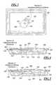
- FIG. 3is a top view of a first embodiment of the apparatus according to the present invention.
- FIG. 4is a cross-sectional side view of the apparatus of FIG. 3 .
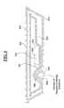
- FIG. 5is a cross-sectional side view of a second embodiment of the apparatus according to the present invention.
- FIG. 6is a cross-sectional side view of a third embodiment of the apparatus according to the present invention.
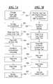
- FIG. 7Ais a schematic flowchart illustrating a first embodiment of the method according to the present invention.
- FIG. 7Bis a schematic flowchart illustrating a second embodiment of the method according to the present invention.
- FIG. 1shows an IMD 102 having a hermetically sealed housing 104 and a connector header 106 .
- the header 106is provided with lead bores 108 for receiving leads having electrodes to be disposed in operative relation to a patient's heart.
- the IMD 102is adapted to be implanted in body tissue.
- the header 106is formed from a suitable dielectric material and houses an RF telemetry antenna 110 for wireless communication, which extends along the periphery of the header 106 .
- the housing 104 of the IMDmay contain a number of functionally elements and components of the IMD, including a battery, a processor, memory elements and a high voltage output capacitor.
- FIG. 2is schematic representation of the IMD 102 of FIG. 1 .
- the housing 104 of the IMDcontains RF transmitter/receiver circuitry 202 connected to the antenna 110 .
- the RF transmitter/receiver circuitry 202 and antenna 110are arranged to wirelessly communicate with an external device comprising transmitter/receiver circuitry and at least one antenna.
- the housing 104contains a therapy module 204 which may include electrical devices, microprocessors, controllers, memory elements and power supply.
- the therapy module 204is arranged to provide the desired functionality associated with the IMD 102 , e.g., defibrillation pulses, pacing simulation and patient monitoring.
- the therapy module 204is arranged to be coupled to one or more therapy leads 206 .
- FIG. 3shows a top view of a first embodiment of the apparatus according to the invention.
- the apparatuscomprises an IMD 102 as shown in FIGS. 1 and 2 , and a container for storing the IMD 102 prior to implantation in body tissue.
- the containerhas a first sealable packaging tray 302 for housing the IMD 102 , which first packaging tray 302 has a support in the form of a recess 304 for receiving and supporting the IMD 102 .
- the containerhas a second sealable packaging tray 306 for housing the first packaging tray 302 .
- the trays 302 , 306are made of a suitable material, such as a rigid plastic material. The seals of the first and second packaging trays 302 , 306 are excluded in FIG. 3 .
- the apparatusincludes an impedance altering substance in the form of one member 308 positioned in proximity to the IMD 102 , when stored in the container, and in proximity to the recess 304 . More precisely, the member 308 is positioned in the close surroundings of the antenna 110 and the recess 304 has such a configuration that the antenna 110 of a stored IMD 102 is positioned in close proximity to the member 308 .
- the member 308extends along a substantial portion of the length of the antenna 110 , and along the edge of the header 106 , and advantageously, the member 308 abuts the header 106 .
- FIG. 4is a cross-sectional side view of the apparatus of FIG. 3 .
- the seal 402 of the first packaging tray 302 and the seal 404 of the second packaging tray 306are shown in FIG. 4 .
- Each seal 402 , 404is formed by a sheet that is glued to a periphery contact face 406 , 408 of respective packaging tray 302 , 306 . These seals are permeable to a sterilizing gas which is used during the packaging process.
- the first packaging tray 302comprises an inner compartment 414 for receiving and retaining the member 308 , and the member 308 is thus positioned on the inside of the first packaging tray 302 .
- the member 308is arranged to mechanically fix the IMD 102 in its position in the first packaging tray 302 .
- FIG. 5is a cross-sectional side view of a second embodiment of the apparatus according to the present invention, comprising an IMD 102 and a member 308 corresponding to the IMD 102 and the member 308 of the embodiment of FIGS. 3 and 4 , but with a different container.
- the inner packaging tray 502is provided an external compartment 504 for receiving and retaining the member 308 , and the member 308 is thus positioned on the outside of the inner packaging tray 502 .
- This position of the member 308is advantageous if the member 308 is formed by a bag with gel or liquid. In case the bag is damaged during storage and gel leaves the bag, the gel will not contaminate the IMD 102 .
- FIG. 6is a cross-sectional side view of a third embodiment of the apparatus according to the present invention, including an IMD 102 and a member 308 corresponding to the IMD 102 and the member 308 of the embodiment of FIGS. 3 and 4 , but with a different container.
- the outer packaging tray 602is provided with an external compartment 604 for receiving and retaining the member 308 , and the member 308 is thus positioned on the outside of the outer packaging tray 602 .
- the inner packaging tray 606is provided with a compartment 608 for receiving the external compartment 604 of the outer packaging tray 602 , such that the member 308 is positioned in close proximity to the header 106 of the stored IMD 102 .
- This position of the member 308is advantageous if the member 308 is formed as a bag with gel or liquid. In case the bag is damaged during storage and gel leaves the bag, the gel will not contaminate the sterilized environment on the inside of the outer packaging tray 602 , and thus not contaminate the outside of the inner packaging tray 606 .
- the membercould also be positioned on the outside of the second packaging tray and still be in proximity to the antenna of the IMD.
- the whole inner traywill be kept sterile during storage, i.e. including the outside of the inner tray and the inside of the outer tray. This is advantageous in the surgical theatre during the implementation process when the IMD will be unpacked.
- the member 308Is formed as a bag 308 filled with a gel.
- the dielectric constant and conductivity of the member 308are set such that the input impedance of the antenna 110 is passively adjusted to improve receive and transmit properties of the antenna 110 when the implantable medical device is stored in the container.
- the dielectric constant of the memberis between 10 and 60, and more precisely between 30 and 40.
- the input impedance of the antennaBy passively altering the electrical material properties of the container in the surroundings of the antenna of the IMD such that they better correspond to the electrical material properties of body tissue, the input impedance of the antenna, when the IMD is stored in the container, corresponds better to the input impedance of the antenna when the IMD is implanted and located in body tissue, whereby the antenna is matched to the transmitter/receiver circuitry of the IMD also when the IMD is stored in the container.
- the efficiency of the antenna outside the body tissueis thereby improved, and thus the telemetry communication between an external device and an implantable medical device stored prior to implantation is improved.
- the inventionalso relates to a container as described above that embodies such a member.
- FIG. 7Ais a schematic flow diagram illustrating two embodiments of the method according to the present invention.
- a first of these embodimentsincludes the steps of providing an inner packaging tray with a compartment on the inside of the inner packaging tray, at 701 , and fixing the above-mentioned bag in the compartment on the inside of said tray, at 702 .
- the inner packaging trayis placed inside an outer packaging tray, at 703 .
- An IMDis placed in a recess formed by the inner packaging tray, at 704 , such that bag is positioned in the close surroundings of the antenna and along a substantial portion of the length of the antenna.
- the IMDis mechanically fixed in its position in the recess by means of the bag, at 705 .
- the inner trayis sealed, at 706
- the outer packaging trayis sealed, at 707 , whereby the outer packaging tray fully encloses the inner packaging tray.
- the interior of outer packaging, including the inner packaging is tray,is sterilized by guiding a sterilizing gas through the permeable seal of the outer and the inner packaging tray, at 708 .
- the packaging traysare inserted in a box, e.g., a cardboard box.
- FIG. 7BA second embodiment of the method according to the present invention is shown in FIG. 7B and includes the steps of providing an inner packaging tray with a compartment on the outside of the inner packaging tray, at 801 , and fixing the above-mentioned bag in the compartment on the outside of the inner packaging tray, at 802 .
- the inner packaging trayis placed inside an outer packaging tray, at 803 .
- An IMDis placed in a recess formed by the inner packaging tray, at 804 , such that bag is positioned in the close surroundings of the antenna and along a substantial portion of the length of the antenna.
- the following steps 805 , 806 and 807correspond to the above-mentioned steps 706 to 708 .
- the outer packaging trayis provided with a compartment on the outside of the outer packaging tray, and the bag is fixed in this compartment on the outside of the outer packaging tray.
Landscapes
- Health & Medical Sciences (AREA)
- Engineering & Computer Science (AREA)
- Biomedical Technology (AREA)
- Nuclear Medicine, Radiotherapy & Molecular Imaging (AREA)
- Radiology & Medical Imaging (AREA)
- Life Sciences & Earth Sciences (AREA)
- Animal Behavior & Ethology (AREA)
- General Health & Medical Sciences (AREA)
- Public Health (AREA)
- Veterinary Medicine (AREA)
- Packages (AREA)
Abstract
Description
Claims (48)
Applications Claiming Priority (1)
| Application Number | Priority Date | Filing Date | Title |
|---|---|---|---|
| PCT/SE2007/000397WO2008130292A1 (en) | 2007-04-24 | 2007-04-24 | A system, an apparatus and a container for storing an implantable medical device, and a method for packaging such a device |
Publications (2)
| Publication Number | Publication Date |
|---|---|
| US20100114247A1 US20100114247A1 (en) | 2010-05-06 |
| US8457755B2true US8457755B2 (en) | 2013-06-04 |
Family
ID=39875722
Family Applications (1)
| Application Number | Title | Priority Date | Filing Date |
|---|---|---|---|
| US12/531,593Expired - Fee RelatedUS8457755B2 (en) | 2007-04-24 | 2007-04-24 | Container for storing an implantable medical device and a method for packaging such a device |
Country Status (3)
| Country | Link |
|---|---|
| US (1) | US8457755B2 (en) |
| EP (1) | EP2150313B1 (en) |
| WO (1) | WO2008130292A1 (en) |
Cited By (3)
| Publication number | Priority date | Publication date | Assignee | Title |
|---|---|---|---|---|
| US20130178702A1 (en)* | 2011-05-30 | 2013-07-11 | Olympus Medical Systems Corp. | Antenna apparatus, antenna, antenna holder, and body-insertable apparatus system |
| US20180222655A1 (en)* | 2017-02-06 | 2018-08-09 | DePuy Synthes Products, Inc. | Packaging Assembly |
| US11742959B2 (en) | 2021-08-25 | 2023-08-29 | Medtronic, Inc. | System and method for wireless communications |
Families Citing this family (11)
| Publication number | Priority date | Publication date | Assignee | Title |
|---|---|---|---|---|
| US7712606B2 (en)* | 2005-09-13 | 2010-05-11 | Sadra Medical, Inc. | Two-part package for medical implant |
| JP5319778B2 (en)* | 2008-10-16 | 2013-10-16 | カーディアック ペースメイカーズ, インコーポレイテッド | Header outer periphery RF antenna |
| EP2875845B1 (en)* | 2013-11-21 | 2016-02-24 | BIOTRONIK SE & Co. KG | Sterilizable containment for implantable medical device |
| US9837839B2 (en)* | 2015-01-19 | 2017-12-05 | Orrex Medical Technologies, LLC | Portable device and method of supplying power to a portable device |
| WO2016118316A1 (en)* | 2015-01-19 | 2016-07-28 | Orrex Medical Technologies, LLC | Portable device and method of supplying power to a portable device |
| US11183855B2 (en)* | 2016-01-04 | 2021-11-23 | Peleton Surgical, Llc | Portable device and method of supplying power to a portable device |
| US10700538B2 (en)* | 2016-01-04 | 2020-06-30 | Peleton Surgical, Llc | Portable device and method of supplying wireless power to a portable device in a sterile environment |
| WO2019143411A1 (en)* | 2017-12-04 | 2019-07-25 | Peleton Surgical, Llc | Portable device and method of supplying power to a portable device |
| US11040210B2 (en) | 2018-04-02 | 2021-06-22 | Pacesetter, Inc. | All metal enclosed implantable medical device with external BLE antenna for RF telemetry |
| JP2020171680A (en) | 2019-04-05 | 2020-10-22 | バイオトロニック エスエー アンド カンパニー カーゲーBIOTRONIK SE & Co. KG | Configuration management of implant in-package imd supporting acoustic communication, self-test, and programming support system |
| EP3718469B1 (en)* | 2019-04-05 | 2023-11-29 | BIOTRONIK SE & Co. KG | In-package imd configuration management, self-test, and programming support system for acoustic communication enabled implants |
Citations (22)
| Publication number | Priority date | Publication date | Assignee | Title |
|---|---|---|---|---|
| US4830005A (en) | 1987-07-23 | 1989-05-16 | Siemens-Pacesetter, Inc. | Disposable in-package load test element for pacemakers |
| US5861019A (en) | 1997-07-25 | 1999-01-19 | Medtronic Inc. | Implantable medical device microstrip telemetry antenna |
| US6292697B1 (en) | 2000-02-15 | 2001-09-18 | Medtronic, Inc. | Testing sterile packaged components of an implantable medical device prior to chronic implantation |
| US20020117408A1 (en)* | 2001-02-27 | 2002-08-29 | Solosko Thomas A. | Method and package for increasing electrode shelf life |
| US20020147388A1 (en) | 2001-04-06 | 2002-10-10 | Mass William R. | Passive telemetry system for implantable medical device |
| US20030025645A1 (en) | 2001-08-03 | 2003-02-06 | Cardiac Pacemakers, Inc. | Circumferential antenna for an implantable medical device |
| US20050154428A1 (en) | 2003-12-30 | 2005-07-14 | Ian Bruinsma | Implanted antenna and radio communications link |
| US20050275591A1 (en) | 2000-07-18 | 2005-12-15 | Mineral Lassen Llc | Grounded antenna for a wireless communication device and method |
| US20060020300A1 (en) | 2004-06-09 | 2006-01-26 | David Nghiem | Implantable medical device package antenna |
| US20060045543A1 (en)* | 2004-08-02 | 2006-03-02 | Sony Corporation | Electromagnetism suppressing material, electromagnetism suppressing device, and electronic appliance |
| US20060197494A1 (en) | 2003-10-02 | 2006-09-07 | Medtronic, Inc. | Shipping container for an implantable medical device |
| US20060224206A1 (en) | 2005-03-31 | 2006-10-05 | Dublin Garry L | Optional telemetry antenna for implantable medical devices |
| US20060247712A1 (en) | 2005-04-28 | 2006-11-02 | Fuller Christopher C | Compact and conformal telemetry antennas for implantable medical devices |
| US20060250314A1 (en) | 2000-03-25 | 2006-11-09 | Mineral Lassen Llc | Multiple feed point slot antenna |
| US20070052613A1 (en) | 2005-09-06 | 2007-03-08 | Sebastian Gallschuetz | Radio frequency identification transponder antenna |
| US20070119741A1 (en)* | 2005-11-30 | 2007-05-31 | Wenger William K | Medical device packaging system |
| US20080146871A1 (en)* | 2006-09-06 | 2008-06-19 | Innurvation, Inc. | Ingestible Low Power Sensor Device and System for Communicating with Same |
| US20080185312A1 (en)* | 2007-02-06 | 2008-08-07 | Microsoft Corporation | Display package and carrying case for a handheld device |
| US20090105597A1 (en)* | 2006-10-12 | 2009-04-23 | Innoscion, Llc | Image guided catheter having remotely controlled surfaces-mounted and internal ultrasound transducers |
| US20090240309A1 (en)* | 2002-07-08 | 2009-09-24 | Boston Scientific Neuromodulation Corporation | Folded Antenna For Implanted Medical Device |
| US7637868B2 (en)* | 2004-01-12 | 2009-12-29 | Dexcom, Inc. | Composite material for implantable device |
| US7720544B2 (en)* | 2006-06-09 | 2010-05-18 | Cardiac Pacemakers, Inc. | Systems for enabling telemetry in an implantable medical device |
Family Cites Families (2)
| Publication number | Priority date | Publication date | Assignee | Title |
|---|---|---|---|---|
| US5984102A (en)* | 1992-09-24 | 1999-11-16 | Survivalink Corporation | Medical electrode packaging technology |
| US6708065B2 (en)* | 2001-03-02 | 2004-03-16 | Cardiac Pacemakers, Inc. | Antenna for an implantable medical device |
- 2007
- 2007-04-24EPEP07748062.2Apatent/EP2150313B1/enactiveActive
- 2007-04-24USUS12/531,593patent/US8457755B2/ennot_activeExpired - Fee Related
- 2007-04-24WOPCT/SE2007/000397patent/WO2008130292A1/enactiveApplication Filing
Patent Citations (22)
| Publication number | Priority date | Publication date | Assignee | Title |
|---|---|---|---|---|
| US4830005A (en) | 1987-07-23 | 1989-05-16 | Siemens-Pacesetter, Inc. | Disposable in-package load test element for pacemakers |
| US5861019A (en) | 1997-07-25 | 1999-01-19 | Medtronic Inc. | Implantable medical device microstrip telemetry antenna |
| US6292697B1 (en) | 2000-02-15 | 2001-09-18 | Medtronic, Inc. | Testing sterile packaged components of an implantable medical device prior to chronic implantation |
| US20060250314A1 (en) | 2000-03-25 | 2006-11-09 | Mineral Lassen Llc | Multiple feed point slot antenna |
| US20050275591A1 (en) | 2000-07-18 | 2005-12-15 | Mineral Lassen Llc | Grounded antenna for a wireless communication device and method |
| US20020117408A1 (en)* | 2001-02-27 | 2002-08-29 | Solosko Thomas A. | Method and package for increasing electrode shelf life |
| US20020147388A1 (en) | 2001-04-06 | 2002-10-10 | Mass William R. | Passive telemetry system for implantable medical device |
| US20030025645A1 (en) | 2001-08-03 | 2003-02-06 | Cardiac Pacemakers, Inc. | Circumferential antenna for an implantable medical device |
| US20090240309A1 (en)* | 2002-07-08 | 2009-09-24 | Boston Scientific Neuromodulation Corporation | Folded Antenna For Implanted Medical Device |
| US20060197494A1 (en) | 2003-10-02 | 2006-09-07 | Medtronic, Inc. | Shipping container for an implantable medical device |
| US20050154428A1 (en) | 2003-12-30 | 2005-07-14 | Ian Bruinsma | Implanted antenna and radio communications link |
| US7637868B2 (en)* | 2004-01-12 | 2009-12-29 | Dexcom, Inc. | Composite material for implantable device |
| US20060020300A1 (en) | 2004-06-09 | 2006-01-26 | David Nghiem | Implantable medical device package antenna |
| US20060045543A1 (en)* | 2004-08-02 | 2006-03-02 | Sony Corporation | Electromagnetism suppressing material, electromagnetism suppressing device, and electronic appliance |
| US20060224206A1 (en) | 2005-03-31 | 2006-10-05 | Dublin Garry L | Optional telemetry antenna for implantable medical devices |
| US20060247712A1 (en) | 2005-04-28 | 2006-11-02 | Fuller Christopher C | Compact and conformal telemetry antennas for implantable medical devices |
| US20070052613A1 (en) | 2005-09-06 | 2007-03-08 | Sebastian Gallschuetz | Radio frequency identification transponder antenna |
| US20070119741A1 (en)* | 2005-11-30 | 2007-05-31 | Wenger William K | Medical device packaging system |
| US7720544B2 (en)* | 2006-06-09 | 2010-05-18 | Cardiac Pacemakers, Inc. | Systems for enabling telemetry in an implantable medical device |
| US20080146871A1 (en)* | 2006-09-06 | 2008-06-19 | Innurvation, Inc. | Ingestible Low Power Sensor Device and System for Communicating with Same |
| US20090105597A1 (en)* | 2006-10-12 | 2009-04-23 | Innoscion, Llc | Image guided catheter having remotely controlled surfaces-mounted and internal ultrasound transducers |
| US20080185312A1 (en)* | 2007-02-06 | 2008-08-07 | Microsoft Corporation | Display package and carrying case for a handheld device |
Cited By (4)
| Publication number | Priority date | Publication date | Assignee | Title |
|---|---|---|---|---|
| US20130178702A1 (en)* | 2011-05-30 | 2013-07-11 | Olympus Medical Systems Corp. | Antenna apparatus, antenna, antenna holder, and body-insertable apparatus system |
| US8821380B2 (en)* | 2011-05-30 | 2014-09-02 | Olympus Medical Systems Corp. | Antenna apparatus, antenna, antenna holder, and body-insertable apparatus system |
| US20180222655A1 (en)* | 2017-02-06 | 2018-08-09 | DePuy Synthes Products, Inc. | Packaging Assembly |
| US11742959B2 (en) | 2021-08-25 | 2023-08-29 | Medtronic, Inc. | System and method for wireless communications |
Also Published As
| Publication number | Publication date |
|---|---|
| WO2008130292A1 (en) | 2008-10-30 |
| EP2150313A1 (en) | 2010-02-10 |
| US20100114247A1 (en) | 2010-05-06 |
| EP2150313A4 (en) | 2012-06-27 |
| EP2150313B1 (en) | 2013-06-19 |
Similar Documents
| Publication | Publication Date | Title |
|---|---|---|
| US8457755B2 (en) | Container for storing an implantable medical device and a method for packaging such a device | |
| US7289855B2 (en) | Implantable medical device package antenna | |
| Iqbal et al. | Biotelemetry and wireless powering of biomedical implants using a rectifier integrated self-diplexing implantable antenna | |
| US7319901B2 (en) | Optional telemetry antenna for implantable medical devices | |
| US7392091B2 (en) | Implanted antenna and radio communications link | |
| EP2321006B1 (en) | Adjustable impedance matching circuit | |
| EP2783659B1 (en) | Tibial tray assembly | |
| US11369267B2 (en) | Reconfigurable implantable medical system for ultrasonic power control and telemetry | |
| US7016733B2 (en) | Telemetry antenna for an implantable medical device | |
| US7903043B2 (en) | Radio frequency antenna in a header of an implantable medical device | |
| US8751001B2 (en) | Universal recharging of an implantable medical device | |
| EP2198397B1 (en) | Small gamma shielded shorted patch rfid tag | |
| US20090240309A1 (en) | Folded Antenna For Implanted Medical Device | |
| US20060247711A1 (en) | Telemetry antennas for implantable medical devices | |
| EP2389711A1 (en) | Phased array cofire antenna structure and method for forming the same | |
| EP2875845B1 (en) | Sterilizable containment for implantable medical device | |
| EP3741002A1 (en) | Medical implant with wireless communication | |
| EP2178159B1 (en) | Antenna insulation for an implantable medical device | |
| Miozzi et al. | Performance Comparison of Patch and Loop Antennas for the Wireless Power Transfer and Transcutaneous Telemetry in the 860–960 MHz Frequency Band | |
| US20150328468A1 (en) | Inner packaging for a sterilizable containment and sterilizable containment | |
| Bose et al. | Wireless channel modeling for leadless cardiac pacemaker: Effects ofventricular blood volume | |
| Marcelli et al. | A new hermetic antenna for wireless transmission systems of implantable medical devices | |
| Nakata et al. | Characteristics of a PIFA Mounted on a Cardiac Pacemaker | |
| AU2004240245A1 (en) | An implanted antenna and radio communications link |
Legal Events
| Date | Code | Title | Description |
|---|---|---|---|
| AS | Assignment | Owner name:ST. JUDE MEDICAL AB,SWEDEN Free format text:ASSIGNMENT OF ASSIGNORS INTEREST;ASSIGNOR:SNITTING, TOMAS;REEL/FRAME:023240/0967 Effective date:20080214 Owner name:ST. JUDE MEDICAL AB, SWEDEN Free format text:ASSIGNMENT OF ASSIGNORS INTEREST;ASSIGNOR:SNITTING, TOMAS;REEL/FRAME:023240/0967 Effective date:20080214 | |
| STCF | Information on status: patent grant | Free format text:PATENTED CASE | |
| FPAY | Fee payment | Year of fee payment:4 | |
| MAFP | Maintenance fee payment | Free format text:PAYMENT OF MAINTENANCE FEE, 8TH YEAR, LARGE ENTITY (ORIGINAL EVENT CODE: M1552); ENTITY STATUS OF PATENT OWNER: LARGE ENTITY Year of fee payment:8 | |
| FEPP | Fee payment procedure | Free format text:MAINTENANCE FEE REMINDER MAILED (ORIGINAL EVENT CODE: REM.); ENTITY STATUS OF PATENT OWNER: LARGE ENTITY | |
| LAPS | Lapse for failure to pay maintenance fees | Free format text:PATENT EXPIRED FOR FAILURE TO PAY MAINTENANCE FEES (ORIGINAL EVENT CODE: EXP.); ENTITY STATUS OF PATENT OWNER: LARGE ENTITY | |
| STCH | Information on status: patent discontinuation | Free format text:PATENT EXPIRED DUE TO NONPAYMENT OF MAINTENANCE FEES UNDER 37 CFR 1.362 | |
| FP | Lapsed due to failure to pay maintenance fee | Effective date:20250604 |