US8457714B2 - System and method for a catheter impedance seeking device - Google Patents
System and method for a catheter impedance seeking deviceDownload PDFInfo
- Publication number
- US8457714B2 US8457714B2US12/323,231US32323108AUS8457714B2US 8457714 B2US8457714 B2US 8457714B2US 32323108 AUS32323108 AUS 32323108AUS 8457714 B2US8457714 B2US 8457714B2
- Authority
- US
- United States
- Prior art keywords
- distal end
- contact
- catheter
- impedance
- tissue
- Prior art date
- Legal status (The legal status is an assumption and is not a legal conclusion. Google has not performed a legal analysis and makes no representation as to the accuracy of the status listed.)
- Expired - Fee Related, expires
Links
- 238000000034methodMethods0.000titleclaimsabstractdescription46
- 230000033001locomotionEffects0.000claimsabstractdescription12
- 239000013598vectorSubstances0.000claimsdescription66
- 238000012544monitoring processMethods0.000claimsdescription11
- 210000002216heartAnatomy0.000claimsdescription8
- 238000004364calculation methodMethods0.000claimsdescription7
- 210000005242cardiac chamberAnatomy0.000claimsdescription5
- 239000008280bloodSubstances0.000claimsdescription4
- 210000004369bloodAnatomy0.000claimsdescription4
- 238000013519translationMethods0.000claimsdescription4
- 238000002847impedance measurementMethods0.000claimsdescription3
- 238000012937correctionMethods0.000claimsdescription2
- 230000000737periodic effectEffects0.000claimsdescription2
- 238000001514detection methodMethods0.000abstractdescription28
- 230000000747cardiac effectEffects0.000abstractdescription4
- 238000010586diagramMethods0.000description36
- 206010003658Atrial FibrillationDiseases0.000description15
- 238000002679ablationMethods0.000description11
- 230000003902lesionEffects0.000description11
- 238000003384imaging methodMethods0.000description8
- 210000003492pulmonary veinAnatomy0.000description7
- 230000008685targetingEffects0.000description7
- 230000005355Hall effectEffects0.000description6
- 206010003119arrhythmiaDiseases0.000description6
- 210000005246left atriumAnatomy0.000description6
- 230000003068static effectEffects0.000description6
- 210000003462veinAnatomy0.000description6
- 230000006793arrhythmiaEffects0.000description5
- 230000001314paroxysmal effectEffects0.000description5
- 238000004422calculation algorithmMethods0.000description4
- 238000005259measurementMethods0.000description4
- 238000005457optimizationMethods0.000description4
- 230000002085persistent effectEffects0.000description4
- 210000003484anatomyAnatomy0.000description3
- 230000000712assemblyEffects0.000description3
- 238000000429assemblyMethods0.000description3
- 230000001746atrial effectEffects0.000description3
- 230000001684chronic effectEffects0.000description3
- 238000004070electrodepositionMethods0.000description3
- 230000002439hemostatic effectEffects0.000description3
- 230000010354integrationEffects0.000description3
- 238000002955isolationMethods0.000description3
- 238000013507mappingMethods0.000description3
- 206010003662Atrial flutterDiseases0.000description2
- 238000001574biopsyMethods0.000description2
- 230000015572biosynthetic processEffects0.000description2
- 230000001276controlling effectEffects0.000description2
- 230000003247decreasing effectEffects0.000description2
- 238000003745diagnosisMethods0.000description2
- 230000002708enhancing effectEffects0.000description2
- 230000033764rhythmic processEffects0.000description2
- 210000005245right atriumAnatomy0.000description2
- 208000034053Accessory Atrioventricular BundleDiseases0.000description1
- 206010003130Arrhythmia supraventricularDiseases0.000description1
- 238000012935AveragingMethods0.000description1
- 208000006017Cardiac TamponadeDiseases0.000description1
- 206010016717FistulaDiseases0.000description1
- 206010029458Nodal arrhythmiaDiseases0.000description1
- 208000008058Reciprocating TachycardiaDiseases0.000description1
- 230000002411adverseEffects0.000description1
- 238000003491arrayMethods0.000description1
- 210000001367arteryAnatomy0.000description1
- 210000003403autonomic nervous systemAnatomy0.000description1
- 238000010009beatingMethods0.000description1
- 238000011088calibration curveMethods0.000description1
- 238000013153catheter ablationMethods0.000description1
- 238000004891communicationMethods0.000description1
- 238000012790confirmationMethods0.000description1
- 210000004351coronary vesselAnatomy0.000description1
- 230000008878couplingEffects0.000description1
- 238000010168coupling processMethods0.000description1
- 238000005859coupling reactionMethods0.000description1
- 230000006378damageEffects0.000description1
- 230000001419dependent effectEffects0.000description1
- 238000013461designMethods0.000description1
- 238000002405diagnostic procedureMethods0.000description1
- 208000037265diseases, disorders, signs and symptomsDiseases0.000description1
- 238000002001electrophysiologyMethods0.000description1
- 230000007831electrophysiologyEffects0.000description1
- 238000001839endoscopyMethods0.000description1
- 230000003890fistulaEffects0.000description1
- 238000002594fluoroscopyMethods0.000description1
- 230000000574ganglionic effectEffects0.000description1
- 238000003780insertionMethods0.000description1
- 230000037431insertionEffects0.000description1
- 230000000670limiting effectEffects0.000description1
- 230000004807localizationEffects0.000description1
- 230000007246mechanismEffects0.000description1
- 210000004115mitral valveAnatomy0.000description1
- 210000000056organAnatomy0.000description1
- 230000008569processEffects0.000description1
- 230000001681protective effectEffects0.000description1
- 238000007674radiofrequency ablationMethods0.000description1
- 230000001105regulatory effectEffects0.000description1
- 238000007634remodelingMethods0.000description1
- 230000004044responseEffects0.000description1
- 239000000523sampleSubstances0.000description1
- 238000005070samplingMethods0.000description1
- 230000035939shockEffects0.000description1
- 238000006467substitution reactionMethods0.000description1
- 239000000758substrateSubstances0.000description1
- 230000000153supplemental effectEffects0.000description1
- 230000009885systemic effectEffects0.000description1
- 230000001225therapeutic effectEffects0.000description1
- 238000002560therapeutic procedureMethods0.000description1
- 238000004448titrationMethods0.000description1
- 210000000591tricuspid valveAnatomy0.000description1
- 230000001960triggered effectEffects0.000description1
- 210000001631vena cava inferiorAnatomy0.000description1
- 210000002620vena cava superiorAnatomy0.000description1
- 206010047302ventricular tachycardiaDiseases0.000description1
Images


Classifications
- A—HUMAN NECESSITIES
- A61—MEDICAL OR VETERINARY SCIENCE; HYGIENE
- A61B—DIAGNOSIS; SURGERY; IDENTIFICATION
- A61B5/00—Measuring for diagnostic purposes; Identification of persons
- A61B5/06—Devices, other than using radiation, for detecting or locating foreign bodies ; Determining position of diagnostic devices within or on the body of the patient
- A—HUMAN NECESSITIES
- A61—MEDICAL OR VETERINARY SCIENCE; HYGIENE
- A61B—DIAGNOSIS; SURGERY; IDENTIFICATION
- A61B34/00—Computer-aided surgery; Manipulators or robots specially adapted for use in surgery
- A61B34/30—Surgical robots
- A—HUMAN NECESSITIES
- A61—MEDICAL OR VETERINARY SCIENCE; HYGIENE
- A61B—DIAGNOSIS; SURGERY; IDENTIFICATION
- A61B34/00—Computer-aided surgery; Manipulators or robots specially adapted for use in surgery
- A61B34/70—Manipulators specially adapted for use in surgery
- A61B34/76—Manipulators having means for providing feel, e.g. force or tactile feedback
- A—HUMAN NECESSITIES
- A61—MEDICAL OR VETERINARY SCIENCE; HYGIENE
- A61B—DIAGNOSIS; SURGERY; IDENTIFICATION
- A61B5/00—Measuring for diagnostic purposes; Identification of persons
- A61B5/06—Devices, other than using radiation, for detecting or locating foreign bodies ; Determining position of diagnostic devices within or on the body of the patient
- A61B5/061—Determining position of a probe within the body employing means separate from the probe, e.g. sensing internal probe position employing impedance electrodes on the surface of the body
- A61B5/062—Determining position of a probe within the body employing means separate from the probe, e.g. sensing internal probe position employing impedance electrodes on the surface of the body using magnetic field
- A—HUMAN NECESSITIES
- A61—MEDICAL OR VETERINARY SCIENCE; HYGIENE
- A61B—DIAGNOSIS; SURGERY; IDENTIFICATION
- A61B5/00—Measuring for diagnostic purposes; Identification of persons
- A61B5/06—Devices, other than using radiation, for detecting or locating foreign bodies ; Determining position of diagnostic devices within or on the body of the patient
- A61B5/065—Determining position of the probe employing exclusively positioning means located on or in the probe, e.g. using position sensors arranged on the probe
- A61B5/068—Determining position of the probe employing exclusively positioning means located on or in the probe, e.g. using position sensors arranged on the probe using impedance sensors
- A—HUMAN NECESSITIES
- A61—MEDICAL OR VETERINARY SCIENCE; HYGIENE
- A61B—DIAGNOSIS; SURGERY; IDENTIFICATION
- A61B34/00—Computer-aided surgery; Manipulators or robots specially adapted for use in surgery
- A61B34/20—Surgical navigation systems; Devices for tracking or guiding surgical instruments, e.g. for frameless stereotaxis
- A61B2034/2046—Tracking techniques
- A61B2034/2051—Electromagnetic tracking systems
- A—HUMAN NECESSITIES
- A61—MEDICAL OR VETERINARY SCIENCE; HYGIENE
- A61B—DIAGNOSIS; SURGERY; IDENTIFICATION
- A61B34/00—Computer-aided surgery; Manipulators or robots specially adapted for use in surgery
- A61B34/30—Surgical robots
- A61B2034/301—Surgical robots for introducing or steering flexible instruments inserted into the body, e.g. catheters or endoscopes
- A—HUMAN NECESSITIES
- A61—MEDICAL OR VETERINARY SCIENCE; HYGIENE
- A61B—DIAGNOSIS; SURGERY; IDENTIFICATION
- A61B90/00—Instruments, implements or accessories specially adapted for surgery or diagnosis and not covered by any of the groups A61B1/00 - A61B50/00, e.g. for luxation treatment or for protecting wound edges
- A61B90/06—Measuring instruments not otherwise provided for
- A61B2090/064—Measuring instruments not otherwise provided for for measuring force, pressure or mechanical tension
- A61B2090/065—Measuring instruments not otherwise provided for for measuring force, pressure or mechanical tension for measuring contact or contact pressure
Definitions
- the inventionrelates to the placement of catheters in contact with specific anatomical locations while optimizing the direction and orientation of tissue contact.
- Intracardiac electrode cathetershave been developed for defining the diagnosis of arrhythmias and for delivering ablative energy to specific intracardiac sites.
- arrhythmiasthat are susceptible to treatment with catheter ablation include: atrial fibrillation, atrial flutter, ablation of accessory atrio-ventricular pathways, AV nodal reciprocating tachycardia, ectopic atrial rhythms, ventricular tachycardia arising in either chamber or near the semilunar valves.
- Atrial fibrillationcan be ‘paroxysmal’, ‘persistent’ or ‘chronic.’ Haissaguerre is credited with having made the observation that paroxysmal AF is frequently triggered by a focal ‘trigger’, most frequently in one of the four pulmonary veins that insert into the left atrium. He further reported that ablation of such a trigger can eradicate paroxysmal AF. In patients with persistent or chronic AF, it appears that atrial ‘remodeling’ takes place which somehow augments the number of triggers or ‘drivers’ that initiate and perpetuate AF.
- the AF ‘drivers’are probably located further away from the ostia of the pulmonary veins. It is also thought that the autonomic nervous system plays a role in both paroxysmal and persistent AF, and that ablation at or near ganglionic plexi in the left atrium might be effective in the treatment of AF.
- Some physiciansalso advocate searching for sites in the left atrium which manifest specific electrogram characteristics, such as continuous, low amplitude fragmented signals.
- the superior vena cava in the right atriumis also electrically isolated, when triggers can be demonstrated to originate from this structure.
- a line of lesionsis often created in the floor of the right atrium, connecting the tricuspid valve annulus to the inferior vena cava.
- 3D electroanatomic and impedance mapping systemsare in use (CARTO, Biosense Webster, and EnSite NavX, St Jude Medical). These systems facilitate the creation of anatomic depictions of the left atrium. Recently, in an attempt to optimize catheter localization, these systems have also evolved to permit the integration of pre-acquired CT and MRI images with real-time 3D maps.
- image integrationOne limitation associated with image integration is the potential for chamber wall deformation by catheter pressure on the endocardial surface of the heart; this can result in an inaccurate map and suboptimal image integration.
- Other limitations of current mapping systemsinclude the occasional creation of anatomic “false spaces”, i.e., computer depiction of regions that do not correspond to true anatomic structures.
- Adverse outcomescan include tissue perforation with resultant pericardial tamponade and systemic shock, formation of thrombi at the site of ablation or on the tip of the catheter, inadvertent damage to important structures such as coronary arteries or the normal conduction system, late formation (1-2 weeks post-procedure) of an esophageal-left atrial fistula. It is likely that these complications are, at least in part, related to inadequate temperature and energy regulation available in current ablation systems.
- the catheteris guided to the specified surface location by synchronizing the average position of the catheter with the average position of the surface location, represented by a point on the anatomical map.
- the prior arthas been concerned with the placement of the distal portion of the catheter or medical device with respect to the current location and orientation, or with respect to a location on a static geometric map.
- the prior arthas difficulty in acquiring and maintaining continuous tissue contact in the presence of a dynamic moving frame using static positional reference points. Such reference points, comprising the anatomical map, cannot account for the current location of the actual surface.
- CGCICatheter Guidance Control and Imaging
- the system and methods described hereincorrect problems arising from the prior art's inability to assess in a real-time fashion whether or not the catheter is actually in contact with endocardial tissue, the actual pressure exerted by the catheter tip, the actual stability of the catheter on any particular anatomic site, and the absence of a real-time assessment of the size of the lesion being formed during RF application.
- These systems and methodimprove over current techniques such as fluoroscopy by providing tactile feed-back to the clinician's hands (the “feel” of the catheter), and/or electrogram characteristics.
- the map formed by the 3D mapping systemcreates actual anatomic borders. Confirmation of true and stable electrode-tissue contact allows for employing the lowest amount of energy for safe lesion creation. The improved accuracy of the map allows for excellent stability of the catheter electrode tip-tissue contact, thereby reducing errors in the amount of energy applied to the cardiac surface. Relatively real-time impedance measurement allows for relatively real-time titration of energy delivery using the closed-loop feedback system.
- the system and methods hereinimprove the accuracy of the generated 3D map while decreasing the time that is required for creation of this map, increase the clinical success rate by assuring the contiguity of the RF lesions (at least in part by enhancing the ability of the catheter to reach all important anatomic sites, and by monitoring the size and depth of the lesions created by RF application), reduce or eliminating complications due to catheter delivery of RF energy by more accurately gauging the pressure exerted by the catheter against the chamber wall, and decreasing the length of time required for these procedures.
- an introduceris inserted into a patient via a vein or orifice, and the distal end guided to the area of interest.
- a Lorentz Active Sheath (LAS) introduceris a modified introducer which has embedded electrodes and is thereby detectable by a Lorentz Catheter Position Detection System (CPDS).
- CPDSLorentz Catheter Position Detection System
- a catheteris inserted via the LAS sheath and the catheter's distal tip is extended into the area of interest.
- the proximal ends of the LAS and catheter shaftare attached to the catheter impedance-seeking device's (CISD) mechanical control fixtures.
- CISDcatheter impedance-seeking device's
- the inventionWhen an anatomical location is selected within the Catheter Guidance Control and Imaging system (CGCI), the invention first uses the geometric map and location information to optimize the workspace and direction of tissue contact by rotating, advancing or retracting the LAS sheath. As the CGCI guides the tool to the desired location, the higher speed tissue impedance-seeking logic attempts to acquire and maintain tissue contact by advancing or retracting the catheter using tip location and contact information. The CGCI system activates the impedance-seeking system whenever it is attempting to reach continuous tissue contact. When contact is made and maintained, the impedance-seeking logic sends the CGCI a continuous-contact signal.
- CGCICatheter Guidance Control and Imaging system
- the impedance-seeking logicmay selectively retract the tip from tissue contact and try again, or it may stop and alert the CGCI as to the amount of error and allow the CGCI to decide what actions to perform next.
- the impedance-seeking logicwill alert the CGCI system to plan a path around the obstacle.
- the Lorentz-Active Sheathserves as a conduit for other medical devices, such as catheters, balloons, biopsy needles, etc.
- the sheathis inserted into a vein or other body orifice and is guided into the area where the operation is to be performed.
- the position and orientation of the LASis tracked via a position detection system which emits electrical signals that are sensed through several electrodes coupled to the LAS.
- the signals received from the LASare used to calculate an accurate and reliable assessment of the actual position of the LAS within the patient.
- the Catheter Position Detection Systemcan be a conventional Lorentz positioning system, such as, for example, the EnSite system from St. Jude Medical Inc. Atrial Fibrillation Division, which sends electrical signals through patches placed upon the patient. These electrical signals are detected through electrodes on the surface of the catheters, giving the position of each electrode.
- the Tissue Contact Detectoris a Lorentz positioning system accessory device which differentiates between the impedance signals from tissue contact and blood-pool contact.
- the Tissue Contact Detectoroperates inside of the CPDS system, and is electrically connected to the distal electrode of the catheter.
- the CGCIuses the Catheter Position Detection System (CPDS) information and a magnetic chamber to push, pull, and steer a magnetically-tipped catheter.
- the operatoruses a virtual tip controller to specify a desired catheter position and orientation, DP, in the CGCI.
- the CGCIdirects the tip to DP using the actual position and orientation of the catheter, AP, which is received from the CPDS.
- the CGCI systemincludes a system whereby a magnetic tip attached to a surgical tool is detected, displayed and influenced positionally so as to allow diagnostic and therapeutic procedures to be performed rapidly, accurately, simply, and intuitively.
- the tools that can be so equippedinclude catheters, guidewires, and secondary tools such as lasers and balloons, in addition biopsy needles, endoscopy probes, and similar devices.
- the magnetic tipallows the position and orientation of the tip to be determined by analyzing a magnetic field (with or without supplemental use of other systems, such as, for example, x-rays, ultrasonics, etc.).
- the magnetic tipfurther allows the tool tip to be pulled, pushed, turned, and forcefully held in the desired position by applying an appropriate magnetic field external to the patient's body.
- a Virtual Tip(a multi-axis joystick-like device providing up to six degrees of freedom or more) serves as an operator control. Movement of the operator control produces corresponding movement of the magnetic tip inside the patient's body.
- controlprovides tactile feedback to the operator's hand in the appropriate axis or axes if the magnetic tip encounters an obstacle.
- the output of the control combined with the magnetic tip position and orientation feedbackallows a servo system to control the external magnetic field by pulse width modulating the positioning electromagnet.
- Data concerning the dynamic position of a moving body part, such as a beating heartoffsets the servo systems response in such a way that the magnetic tip, and hence the secondary tool is caused to move in unison with the moving body part.
- the tip position and orientation information and the dynamic body part position informationare also utilized to provide a display that allows three dimensional viewing of the magnetic tip position and orientation relative to the body part.
- an amount of tactile feedbackis computed based at least in part on a difference between a desired position and an actual position of the catheter tip position.
- tactile feedbackis provided as a feedback vector computed based on a difference between a desired position vector (e.g., desired position and orientation) of the catheter tip and an actual position vector (e.g., actual position and orientation) of the catheter tip.
- tactile feedbackcan be different as the virtual tip is moved in different directions (e.g., in connection with the different degrees of freedom).
- tactile feedbackis filtered to reduce noise.
- tactile feedbackis threshold filtered such that errors below a certain threshold do not produce tactile feedback.
- the Catheter Position Detection Systemis the CGCI Magnetic Catheter Position Detection System, including a method and apparatus for detecting position and orientation of catheter distal magnetic element while it moves in a patient's heart.
- the apparatusincludes four or more sensors for detecting the magnetic field generated by the catheter tip. The sensors transmit the field magnitude and direction to a detection unit, which filters the signals and removes other field sources, such as generated by CGCI coils and external medical hardware. The method allows the measurement of magnitude corresponding to the catheter tip distance from the sensor and the orientation of the field showing the magnetic tip orientation. Since the tip's magnetic field is not symmetric, the position and orientation computation technique are not independent of each other.
- an iterative calculationis used to converge to a solution.
- the method of determining tip positionis calculated by triangulation from each sensor, and whereby the tip orientation is calculated by an intersecting-planes algorithm.
- the orientationis used to adjust the distances from each sensor, and the process is repeated until convergence for both position and orientation is achieved.
- the resultant valueprovides the actual catheter tip position and orientation (AP).
- the actual positionis further filtered by synchronizing the AP measurements with the QRS signal of the heart, allowing the operator and CGCI controller to view the organ as a static object.
- a controllable magnetic field sourceproduces a magnetic field to guide a tool (e.g., catheter, introducer, Lorenz sheath, guidewire, etc.) having a distal end responsive to the magnetic field.
- a toole.g., catheter, introducer, Lorenz sheath, guidewire, etc.
- One or more sensorsare configured to sense a current vector position of the distal end by measuring one or more impedances.
- a controllercontrols the magnetic field source to control a movement of the distal end according to a feedback calculation wherein the system controller is configured to compute a position error comprising a difference between a desired vector position of the distal end and the current vector position of the distal end.
- An operator controlis used to provide tactile feedback to an operator when the position error exceeds a predetermined amount, wherein the tactile feedback is computed by the controller at least in part according to the vector position error.
- a correction input to the desired vector positionis computed based on a position of a heart relative to a frame of reference, such that the system controller compensates for a dynamic position of a wall of a heart chamber such that the distal end maintains contact with the wall of the heart chamber at least in part by measuring at least one impedance between the distal end and the wall.
- the toolincludes a Lorenz sheath.
- one or more patchesare provided to the patient, wherein the apparatus measures a position and orientation of a Lorenz sheath at least in part by measuring one or more impedances between the Lorenz sheath and the conductive patches.
- the controlleris configured to control the magnetic field source to maintain the distal end in a desired vector orientation relative to the wall (e.g., an interior wall of a heart chamber, artery, vein, or other anatomical structure). In one embodiment, the controller is configured to control the magnetic field source to maintain the distal end substantially normal to the wall. In one embodiment, the controller is configured to differentiate between contact with the wall and contact with an obstruction by analyzing differences between a measured impedance and an expected impedance. In one embodiment, the controller is configured to compute a path around the obstruction. In one embodiment, the controller is configured to control the magnetic field source to maintain the distal end in a desired orientation relative to the wall. In one embodiment, the controller is configured to differentiate between contact with the wall and contact with other tissue by analyzing differences between a measured impedance and an expected impedance, the expected impedance corresponding to the wall. In one embodiment, the other tissue includes a blood pool.
- the controlleris configured to seek contact with the wall by calculating a target manifold, monitoring a distal end-to-target vector with respect to the target manifold, calculating a new tool length, and adjusting a length of the tool according to the new tool length.
- the toolincludes an introducer.
- the controllercontrols a rotation and translation of the introducer.
- a method for positioning a surgical tool and maintaining relatively continuous contact between a distal end of the tool and a desired tissue locationincludes controlling a position and orientation of a distal end of a surgical tool by adjusting currents in a plurality of electromagnets, measuring a plurality of impedance values between the distal end and a plurality of tissue locations, constructing an impedance map at least in part form the plurality of impedance values, determining a first impedance value corresponding to an impedance measured when the distal end touches the desired tissue location, and using a feedback controller to control the currents to maintain contact between the distal end and the desired tissue such that the distal end is oriented relatively normal to the desired tissue location in the presence of motion of the desired tissue location, wherein feedback information to the feedback controller includes periodic impedance measurements between the distal end and the desired tissue location.
- the methodfurther includes, computing a position error comprising a difference between a desired vector position of the distal end and the current vector position of the distal end, and providing tactile feedback to an operator control when the position error exceeds a predetermined amount, wherein the tactile feedback is computed at least in part according to the position error.
- the methodincludes locating the distal end by measuring impedances between a plurality of patches provided to the patient and the surgical tool.
- the methodincludes differentiating between contact with the desired tissue location and contact with an obstruction by analyzing differences between a measured impedance and an expected impedance. In one embodiment, the method includes computing a path around the obstruction.
- the methodincludes distinguishing between contact with the desired tissue location and contact with other tissue by analyzing differences between a measured impedance and an expected impedance, the expected impedance corresponding to an impedance at the desired tissue location.
- the other tissueincludes a blood pool.
- the methodincludes seeking contact with the desired tissue location by calculating a target manifold, monitoring a distal end-to-target vector with respect to the target manifold, calculating a new tool length, and adjusting a length of the tool according to the new tool length.
- the toolincludes an introducer.
- the methodincludes controlling a rotation and translation of the tool.
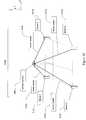
- FIG. 1is a schematic diagram of the signals and systems used in tissue impedance seeking.
- FIG. 2is a block diagram of the Tissue Impedance-Seeking Logic.
- FIG. 3is a schematic diagram of a catheter in relationship to the virtual and real tissue surface with associated control vector information.
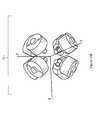
- FIG. 4Ais an isometric diagram of the Lorentz-Active Sheath (LAS) assembly and the associated vectors used in workspace optimization.
- LASLorentz-Active Sheath
- FIG. 4Bis a block diagram of the signals and systems used to determine the position of the LAS Electrodes.
- FIG. 5is a logic flow diagram of the CISD Track Path to Tissue Contact routine.
- FIG. 6is a logic flow diagram of the CISD Continuous Contact Monitoring routine.
- FIG. 7is a logic flow diagram of the CISD Sheath Position Optimization routine.
- FIG. 8is a vector diagram of the sheath rotation angle calculation.
- FIG. 9Ais a block diagram of the CGCI Position Detection System.
- FIG. 9Bis a schematic diagram of a Hall-Effect sensor in relationship to the catheter tip, and its generated measurement data.
- FIG. 9Cis a schematic diagram of a catheter position triangulation using four Hall-Effect sensors and their respective range values.
- FIG. 9Dis a detailed schematic of the triangulation of the catheter position's X-coordinate using two sensors.
- FIG. 9Eis a diagram of the Intersecting Planes Method for determining the orientation of a magnetic catheter tip from its position and two sensor's magnetic field values.
- FIG. 9Fis a block diagram of the method for determining both position and orientation when they are not independent values.
- FIG. 10Ais a diagram of the signals and systems used in catheter position control.
- FIG. 10Bis an isometric diagram of another embodiment of the magnetic chamber used to control catheter position.
- FIG. 10Cis an isometric diagram of a virtual tip assembly.
- FIG. 11Ais a block diagram of the signals and systems of the CISD Mechanical Assembly and CISD Motor Controller.
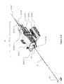
- FIG. 11Bis an isometric drawing of an embodiment of the CISD Mechanical Assembly.
- FIG. 11Cis an isometric detail drawing of the internal assemblies within the CISD Mechanical Assembly.
- FIG. 11Dis an isometric drawing showing the sheath shuttle in a forward position.
- FIG. 11Eis an isometric detail drawing of the sheath rotator housing.
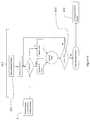
- FIG. 1is a schematic diagram of the signals and systems used in tissue impedance seeking.
- a catheter 3is inserted through a sheath (LAS introducer) 4 and into a patient 1 .
- a catheter tip 3 . 1is advanced into the patient and a catheter shaft 3 . 2 is connected within a CISD Mechanical Assembly 11 to a Catheter Shuttle 11 . 2 .
- the proximal portion of the LAS sheath 4is provided to a Sheath Shuttle 11 . 3 .
- the proximal end of the catheter shaft 3 . 1is connected to both the Tissue Contact Level Detector 8 and a Catheter Position Detection System (CPDS) 7 by the catheter electrical connector.
- CPDSCatheter Position Detection System
- the sheath position and orientation, SP 40is also detectable by the CPDS 7 , so the sheath 4 is also provided to the CPDS 7 by an electrical connector.
- the Catheter Position Detection System 7uses the signals from the catheter and from the Catheter Position Detection System Patches 7 . 3 , placed on the patient 1 , to determine catheter position and orientation, which is passed on to the Catheter Guidance Control and Imaging System (CGCI) 15 .
- the CGCI 15uses electromagnets 15 . 1 to push, pull and steer the catheter tip 3 . 1 within the patient 1 .
- the CGCI 15operates in a closed-loop regulation mode with the Catheter Position Detection System 7 to synchronize the Desired Position and Orientation, DP 30 , of the catheter tip 3 . 1 with the Actual Position and Orientation, AP 20 , of the catheter tip 3 . 1 .
- the CGCI 15is directed by the operator to seek a location on the tissue surface at or near DP 30 , the CGCI sends the Tissue Impedance-Seeking Logic routines 10 the Geometric Target Distance vector 15 . 1 , the Geometric Normal Vector 15 . 3 (shown in FIG. 3 ) for tissue contact direction, and a command to Seek Tissue Contact 15 . 2 .
- the Tissue Impedance Seeking Logic 10uses the CISD Motor Controller 12 to extend or retract the sheath 4 , rotate the sheath, or extend or retract the catheter 3 in cooperation with the CGCI's magnetic regulation.
- the Tissue Impedance-Seeking Logicsends a Contact Found signal 10 . 1 to the CGCI 15 .
- the Tissue Impedance-Seeking Logic 10contains routines that optimize the direction of tissue contact, detect obstructions and provide the CGCI 15 additional geometric information about the tissue surface.
- the Catheter Position Detection SystemCPDS is the CGCI Magnetic Catheter Position Detection System which uses a set of magnetic sensors 9 . 1 to determine catheter tip position and orientation, as described later in this document.
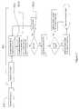
- FIG. 2is a block diagram of the Tissue Impedance-Seeking Logic 10 .
- the Catheter Guidance Control and Imaging System 15provides the Tissue Impedance-Seeking Logic 10 with the Geometry Normal Vector 15 . 3 , Actual Catheter Position and Orientation, AP 20 , Desired Catheter Position and Orientation, DP 30 , Sheath Position and Orientation, SP 40 , and commands to Seek Tissue Contact 15 . 5 and Optimize Workspace 15 . 6 .
- the Tissue Impedance-Seeking Logic routinesuse the geometric information to calculate a Tissue Contact Manifold 10 . 7 (see FIG.
- the Tissue Impedance-Seeking Logic routines 10provide the CGCI 15 with live tissue contact information 8 . 1 , as well as a Continuous Contact Found signal 10 . 6 , which indicates that the catheter has had continuous contact with the surface with the specified contact strength and for the desired length of time.
- the CISD Obstacle Detection Routine 10 . 4signals the CGCI that a new path to tissue contact will be specified.
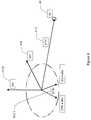
- FIG. 3is a schematic diagram of a catheter in relationship to the virtual and real tissue surface with associated control vector information.
- the Catheter 3is guided by the Catheter Guidance Control and Imaging System 15 from its current Actual Position and Orientation, AP 20 , through the Desired Position and Orientation, DP 30 .
- DP 30is on the surface of the CGCI's Geometric Map 15 . 7 , and not on the actual Patient Tissue Surface 1 . 2 , so the catheter is guided on a path to the surface, called the CISD Tissue Contact Targeting Manifold 10 . 7 until it makes continuous contact with the tissue surface, as indicated by the Tissue Contact Detector 8 .
- the CPCS Normal Vector 15is described in the catheter Guidance Control and Imaging System 15 from its current Actual Position and Orientation, AP 20 , through the Desired Position and Orientation, DP 30 .
- DP 30is on the surface of the CGCI's Geometric Map 15 . 7 , and not on the actual
- the CISD Tissue Contact Targeting Manifold 10 . 7is a set of radius values for the targeting manifold at each distance from the desired position, DP 30 . Rm(d) 10 .
- the tip-to-tissue vector, TTV 10 . 11is the negative of the geometric normal vector 15 . 3 times the magnitude of the distance to DP 30 .
- TTV⁇ GNV*
- the tip to path vector, TPV 10 . 10is the vector distance from the catheter tip to the tissue path 10 . 14 passing through DP 30 .
- TPVGNV*
- the advance vector, ADV 10 . 13is the weighted sum of TPV and TTV using the weighting values w 1 10 . 16 and w 2 10 . 17 , which may be adjusted for system performance and anatomical location.
- ADVw 1 *TTV+w 2 *TPV*[
- ADVw 1 *TTV+w 2 *TPV/Rm ( d )
- the advance vector ADV 10 . 13is then used in cooperation with the CGCI 15 to guide the catheter to tissue contact.
- the CGCI 15regulates the magnetic field based on the component of ADV perpendicular to the catheter tip axis 901 , and the CISD 11 advances the tip based on the component of ADV which is parallel to the catheter tip axis 901 .
- FIG. 4Ais an isometric diagram of the Lorentz-Active Sheath (LAS) assembly 4 and the associated vector used in workspace optimization.
- the Lorentz detection system-sensitive electrodes 4 . 3 - 4 . 7are integrated into the LAS shaft 4 . 9 and connected via embedded wires 4 . 2 to a coupling connector.
- the electrodes 4 . 3 - 4 . 7are used to sense electrical signals generated by a Catheter Position Detection System 7 .
- the two most distal electrodes 4 . 3 and 4 . 4are used to determine tool exit position and tool exit direction, SEV 4 . 8 .
- the two most proximal electrodes 14 and 15are used to determine the LAS sheath rotation axis vector, SRV 4 . 10 .
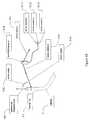
- FIG. 4Bis a block diagram of the signals and systems used to determine the position of the LAS Electrodes 4 . 3 - 4 . 7 .
- the LAS 4is inserted in the patient 1 via a vein or orifice and electrically connected to the Catheter Position Detection System 7 .
- the LAS-hosted tool 3is inserted through the LAS and also connected to the Catheter Position Detection System 7 .
- the position of each electrode 4 . 3 - 4 . 7is provided by the Catheter Position Detection System via a conventional communications link.
- One of ordinary skill in the artcan use these electrode positions to determine the tool exit position and tool exit direction, SEV 4 . 8 and sheath rotation axis, SRV 4 . 10 .
- the tool exit position and tool exit direction SEV 4 . 8are averaged in the Electrode Position Averaging Subsystem 500 and subtracted from the current tool exit position and tool exit direction 4 . 8 in the Electrode Position Error Subsystem 530 to give a Tool Motion Compensation Vector 550 , which is used to remove the LAS motion from the LAS-hosted tool's 3 position.
- the sheath rotation axis SRV 4 . 10aids in determining the motion of the sheath's distal end and tool position while rotating the sheath.
- FIG. 5is a logic flow diagram of the CISD Track Path to Tissue Contact routine 10 . 1 .
- the Seek Tissue Contact Signal 15 . 2 from the CGCI 7begins the monitoring of the catheter tip position, AP 20 , with respect to the Target Manifold 10 . 7 .
- the catheter lengthis recalculated as to progress the catheter tip 3 . 1 down through the Target Manifold 10 . 7 until the Continuous Contact Monitoring routine 10 . 3 has determined that the tip is in continuous tissue contact.
- Signals from the Obstacle Detection routine 10 . 4may also interrupt the CISD Track Path to Tissue Contact routine 10 . 1 when the CGCI 15 is used to steer around an unexpected surface contact.
- FIG. 6is a logic flow diagram of the CISD Continuous Contact Monitoring routine 10 . 3 .
- the CISD Continuous Contact Monitoring routine 10 . 3seeks a period of continuous contact which is greater than the time (Tc) 10 . 9 .
- Tctime
- the Continuous Contact Found signal 10 . 6is sent to all monitoring systems.
- FIG. 7is a logic flow diagram of the CISD Sheath Position Optimization routine 10 . 2 .
- the sheath 4begins in a fully-retracted position.
- the sheathis first rotated, within certain geometric chamber limits, to optimize the alignment between the sheath exit vector, SEV 4 . 8 and the sheath-tip-to-target direction vector, STTV 4 . 11 .
- the sheath insertion lengthis then adjusted depending upon whether the tissue contact may be reached directly, or is to be reached in retrograde fashion, steering the catheter tip 3 . 1 beyond 90 degrees from the sheath exit vector SEV 4 . 8 . If the retracted sheath-tip-to-target vector length is shorter than the length of the catheter tip 3 . 1 , or if the desired position, DP 30 , requires a STTV beyond 90 degrees from the SEV 4 . 8 , the target is considered retrograde.
- FIG. 8is a vector diagram of the sheath rotation angle calculation.
- the sheath targeting angle, STA 10 . 2 . 1is on a plane orthogonal to the sheath rotation vector SRV 4 . 10 .
- STAis defined by the following calculation, which the angle between the cross-products of the sheath rotation vector SRV 4 . 10 with the sheath exit vector SEV 4 . 8 and sheath-to-target vector STTV 4 . 11 .
- STAA COS[(( STTV ⁇ SRV )/
- This valueis evaluated by heuristic logic routines to account for the orientation of the STTV 4 . 11 .
- FIG. 9Ais a block diagram of the CGCI Position Detection System 9 .
- the CGCI Detection System Hardware 9 . 7including four 3-axis Hall-Effect magnetic sensors 9 . 21 - 9 . 24 , amplifiers and associated data acquisition connections, sends four magnetic sensor readings 9 . 1 - 9 . 4 to the CGCI Calibration and Filtering software routines 9 . 6 , where background magnetic fields are subtracted.
- the CGCI QRS Synchronization Unit 9 . 5may then be used to synchronize the readings to the most stable portion of the heartbeat, using a sampling window offset from the heartbeat R-peak signal.
- the four filtered magnetic field vectorsare then used by the Catheter Tip Position and Orientation Calculation Algorithm 9 . 8 to determine the position and orientation of the magnetic catheter tip 3 . 1 .
- FIG. 9Bis a schematic diagram of a Hall-Effect sensor in relationship to the catheter tip, and its generated measurement data.
- the catheter 3 and its magnetic tip 3 . 1are shown in proximity to Hall-Effect sensor number one 9 . 21 , which is connected through the CGCI Position Detection System hardware (not shown) to provide the three magnetic sensor readings 9 . 1 . 1 - 9 . 1 . 3 representing the magnetic field components of magnetic sensor vector number one 9 . 1 in the X, Y, and Z Cartesian directions at the sensor's location.
- the other three magnetic sensorsare defined as 9 . 22 , 9 . 23 , and 9 . 24 with sensor vectors 9 . 2 , 9 . 3 , and 9 . 4 respectively.
- the catheter tip axisis identical to the catheter tip magnetic axis 901 , (which is the directional component of the six-degree of freedom Actual Position, AP 20 ) and the angle between the catheter tip axis and the direction vector from sensor 1 - 4 9 . 21 - 9 . 24 to the catheter tip 3 . 1 is defined as SensorAngle 1 -SensorAngle 4 9 . 61 - 9 . 64 .
- the distances from magnetic sensor 1 - 4 to the catheter tipare defined as SensorRange 1 -SensorRange 4 9 . 41 - 9 . 44 , which have unit direction vectors SensorCatheter 1 -SensorCatheter 4 9 . 51 - 9 . 54 .
- FIG. 9Cis a schematic diagram of a catheter position triangulation 9 . 50 using four Hall-Effect sensors and their respective range values.
- the magnitude of the magnetic field at each sensor 9 . 1 - 9 . 4is converted to a range value SensorRange 1 -SensorRange 4 9 . 41 - 9 . 44 by a magnetic field to distance calibration curve, the sensor ranging dataset 9 . 40 (not shown).
- the positions of magnetic sensor 1 - 4 9 . 11 - 9 . 14are known and fixed values and form the baseline for triangulating the catheter position 904 (which is the positional component of the Actual Position, AP 20 ), which is always above the detection sensor array.
- FIG. 9Dis a detailed schematic of the triangulation of the catheter position's X-coordinate using two sensors, sensor # 2 9 . 22 and sensor # 3 9 . 23 .
- SensorRange 2 9 . 42 and SensorRange 3 9 . 43are used with SensorPosition 2 9 . 12 and SensorPosition 3 9 . 13 to locate the x-coordinate of the catheter position 904 , CatheterPositionX 904 . 1 .
- two solutions for CatheterPositionX 904 . 1 and CatheterPositionY 904 . 2are calculated and averaged.
- CatheterPositionZ 904.
- FIG. 9Eis a diagram of the Intersecting Planes Method 9 . 60 for determining the orientation of a magnetic catheter tip from its position and two sensor's magnetic field values.
- the orientation of the catheter tip's magnetic field axis 901is calculated as being co-planar with each of the magnetic sensor vectors 9 . 1 - 9 . 4 and their corresponding sensor-to-catheter position vectors, SensorCatheter 1 -SensorCatheter 4 9 . 51 - 9 . 54 .
- the sensor-catheter planesdefined by the plane normal vectors 9 . 31 - 9 . 34 , are calculated as the normalized cross-product of the normalized magnetic sensor vectors 9 .
- FIG. 9Fis a block diagram of the method for determining both position and orientation when they are not independent values.
- the Catheter Tip Position and Orientation Calculation Algorithm 9 . 8uses an iterative method to determine catheter position 904 and catheter orientation 901 since the catheter tip magnetic field is not spherical so therefore position and orientation are not independent variables.
- the data for magnetic tip field magnitude versus distance and orientation to the magnetic axisis known and stored internally to the algorithm as a calibrated dataset, the sensor ranging dataset 9 . 40 .
- the magnetic sensor vectors 9 . 1 - 9 . 4are first used to calculate the range from each sensor to the magnetic tip using the sensor ranging dataset 9 .
- the catheter tip position 904is then calculated by triangulation 9 . 50 .
- the catheter position 904is then used to calculate the catheter's magnetic axis 901 using the Intersecting Planes Method 9 . 60 .
- the catheter magnetic axis 901is used to recalculate the SensorRange values from the sensor range dataset 9 . 40 , and then to re-triangulate 9 . 50 the catheter position 904 .
- the catheter axisis then re-calculated as well by the Intersecting Planes Method 9 . 60 .
- the iterative methodhas been determined to be convergent, and when the successive values are within the desired error limits, the catheter position 904 and orientation 901 are known.
- FIG. 10Ais a diagram of the signals and systems used in catheter position control.
- the Catheter Guidance Control and Imaging System (CGCI) 15uses the Catheter Position Detection System (CPDS) 7 information and a magnetic chamber 15 . 1 to push, pull, and steer a magnetically-tipped catheter 3 within the patient 1 .
- the operatoruses the Virtual Tip 34 controller to specify a desired catheter position and orientation, DP 30 , in the CGCI, and the CGCI uses the actual position and orientation of the catheter, AP 20 , which is received from the CPDS to control the catheter in a closed-loop regulation mode.
- the CGCI “Host System” Controller computer 15uses the Catheter Guidance Control and Imaging System (CPDS) 7 information and a magnetic chamber 15 . 1 to push, pull, and steer a magnetically-tipped catheter 3 within the patient 1 .
- the operatoruses the Virtual Tip 34 controller to specify a desired catheter position and orientation, DP 30 , in the CGCI,
- the Console computer 15 . 9serves as the operator interface with a monitor, mouse and keyboard next to the Virtual Tip 34 .
- the Virtual Tip 34is calibrated with an additional calibration fixture 15 . 10 . 1 before the operation begins.
- FIG. 10Bis an isometric diagram of another embodiment of the magnetic chamber used to control catheter position.
- the magnetic chamber 15 . 1is included of eight electromagnetic coils which is an optimized design to generate a magnetic guidance lobe while providing sufficient patient access.
- FIG. 10Cis an isometric diagram of the Virtual Tip assembly 34 .
- the control end of the Virtual Tipcan be moved in six-degrees of freedom, including the X 34 . 1 , Y 34 . 2 , Z 34 . 3 Cartesian directions, Rotated 34 . 4 , Elevated 34 . 5 , and Twisted 34 . 6 .
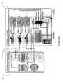
- FIG. 11Ais a block diagram of the signals and systems of the CISD Mechanical Assembly and CISD Motor Controller.
- the CISD Motor Controller 12(for the purposes of this patent is considered an external, off-the-shelf device) controls the position of the CISD Mechanical Assembly 11 (see FIGS. 11B-11E ) components through the CISD Drive Cables 11 . 5 .
- the CISD Motor Controller 12includes a set of three off-the-shelf packaged stepper motors, encoders, limit switches and stepper motor controllers. Each motor assembly actuates one of the three CISD Drive Cables 11 . 5 , two of which are linear drive cables, and one is a rotational drive cable.
- the motor controller assembliesaccept a standard positional signal over the local Ethernet bus.
- FIG. 11Bis an isometric drawing of an embodiment of the CISD Mechanical Assembly 11 .
- the CISD Motor Controller 11 . 1(not shown) controls the device through the CISD Drive Cables ( 11 . 5 . 1 , 11 . 5 . 2 , 11 . 5 . 3 ).
- the CISD Mechanical Assembly 11contains no motors or electronics, and may be sterilized so that it is compatible with a surgical environment.
- the CISD Base Plate 11 . 4 . 1is attached to the CISD Leg Mount 11 . 4 . 2 by the CISD Mount Pin 11 . 4 . 3 which allows the operator to elevate and rotate the CISD Mechanical Assembly 11 , as to align the device within the surgical environment.
- the drive elementsare housed under protective telescoping covers.
- the CISD Outer Cover 11 . 6 . 1is attached to the Sheath Rotator Housing 11 . 3 . 1 on the Sheath Shuttle 11 . 3 (see FIG. 4 ), and the CISD Inner Cover 11 . 6 . 2 is attached to the CISD Base Plate 11 . 4 . 1 .
- the Sheath Shuttle 11 . 3moves forward and backward along the CISD Base Plate 11 . 4 . 1
- the CISD Covers 11 . 61 , 11 . 62telescope over each other.
- the Sheath Shuttle 11 . 3pushes the sheath back and forth with respect to the patient's leg.
- Sheath Shuttle 11 . 3contains gears that rotate the Sheath Rotator Clip 11 . 3 . 2 .
- the proximal end of the Sheath 4has the standard Hemostatic Seal 4 . 1 which is held within the Sheath Rotator Clip 11 . 3 . 2 .
- the Catheter Tip 3 . 1is inserted through the rear of the CISD Mechanical Assembly 11 and through the attached Sheath 4 .
- FIG. 11Cis an isometric detail drawing of the internal assemblies within the CISD Mechanical Assembly.
- the CISD Covers 11 . 6 . 1 , 11 . 6 . 2 and CISD Leg Mounthave been removed for clarity.
- the Sheath Shuttle 11 . 3is moved over the CISD Base Plate 11 . 4 . 1 by the Sheath Shuttle Cable 11 . 5 . 3 .
- the Catheter Shuttle Clamp 11 . 2 . 1is attached to the Catheter Shuttle 11 . 2 and clamps to the Catheter Shaft 3 . 2 .
- the Catheter Shuttle 11 . 2is moved by the Catheter Shuttle Cable 11 . 5 .
- the Sheath Rotator Cable 11 . 5 . 1rotates the gears within the Sheath Rotator Housing 11 . 3 . 1 (see FIG. 6 ), which rotates the Sheath Rotator Clip 11 . 3 . 2 to which is fitted the Sheath Hemostatic Seal 4 . 1 , allowing for the rotation of the Sheath 4 .
- FIG. 11Dis an isometric drawing showing the Sheath Shuttle in a forward position.
- the Sheath Shuttle 11 . 3is moved by the Sheath Shuttle Cable 11 . 5 . 3 .
- the Catheter Shuttle Cable 11 . 5 . 2is attached to the Catheter Shuttle Clamp 11 . 2 . 1 to move the Catheter Line 3 . 2 with reference to the Sheath 4 .
- the end of the Sheath Rotator Cable 11 . 5 . 1telescopes with the Sheath Shuttle 11 . 3 , and drives the gears within the Sheath Rotator Housing 11 . 3 . 1 .
- FIG. 11Eis an isometric detail drawing of the sheath rotator housing. Inside the Sheath Rotator Housing 11 . 3 . 1 , the Sheath Rotator Cable 11 . 5 . 1 turns the Sheath Rotator Drive Gears 11 . 3 . 3 to turn the Sheath Rotator Clip 11 . 3 . 2 . The Sheath's Hemostatic Seal 4 . 1 clips within the Sheath Rotator Clip 11 . 3 . 2 . The Sheath Rotator Torque Limiting Assembly 11 . 3 . 4 limits the amount of torque that may be applied to the sheath, as to keep the mechanical stress within safe limits.
Landscapes
- Health & Medical Sciences (AREA)
- Life Sciences & Earth Sciences (AREA)
- Engineering & Computer Science (AREA)
- Surgery (AREA)
- Veterinary Medicine (AREA)
- Public Health (AREA)
- General Health & Medical Sciences (AREA)
- Biomedical Technology (AREA)
- Heart & Thoracic Surgery (AREA)
- Medical Informatics (AREA)
- Molecular Biology (AREA)
- Animal Behavior & Ethology (AREA)
- Physics & Mathematics (AREA)
- Pathology (AREA)
- Biophysics (AREA)
- Human Computer Interaction (AREA)
- Nuclear Medicine, Radiotherapy & Molecular Imaging (AREA)
- Robotics (AREA)
- Media Introduction/Drainage Providing Device (AREA)
- Measurement And Recording Of Electrical Phenomena And Electrical Characteristics Of The Living Body (AREA)
Abstract
Description
Rm(d)=d2/10+2
Or:Rm(d)=2+d/4
Or:Rm(d)={2,3,4,4,5,6, . . . } for all integersd,0 ton
Or:Rm(d)=4
(etc.) 10.15
TTV=−GNV*|DP−AP| 10.11
TPV=GNV*|AP−DP|*[((AP−DP)/|AP−DP/|·GNV)]−(AP−DP) 10.10
ADV=w1*TTV+w2*TPV*[|TPV|/Rm(d)]/|TPV| 10.13
Which yields:ADV=w1*TTV+w2*TPV/Rm(d)
STA=ACOS[((STTV×SRV)/|STTV∥SRV∥STTV×SRV|·(SEV×SRV)/|SEV∥SRV∥SEV×SRV|] (10.2.2)
Claims (24)
Priority Applications (3)
| Application Number | Priority Date | Filing Date | Title |
|---|---|---|---|
| US12/323,231US8457714B2 (en) | 2008-11-25 | 2008-11-25 | System and method for a catheter impedance seeking device |
| PCT/US2009/064439WO2010065267A1 (en) | 2008-11-25 | 2009-11-13 | System and method for a catheter impedance seeking device |
| EP09756375AEP2381875A1 (en) | 2008-11-25 | 2009-11-13 | System and method for a catheter impedance seeking device |
Applications Claiming Priority (1)
| Application Number | Priority Date | Filing Date | Title |
|---|---|---|---|
| US12/323,231US8457714B2 (en) | 2008-11-25 | 2008-11-25 | System and method for a catheter impedance seeking device |
Publications (2)
| Publication Number | Publication Date |
|---|---|
| US20100130854A1 US20100130854A1 (en) | 2010-05-27 |
| US8457714B2true US8457714B2 (en) | 2013-06-04 |
Family
ID=41445524
Family Applications (1)
| Application Number | Title | Priority Date | Filing Date |
|---|---|---|---|
| US12/323,231Expired - Fee RelatedUS8457714B2 (en) | 2008-11-25 | 2008-11-25 | System and method for a catheter impedance seeking device |
Country Status (3)
| Country | Link |
|---|---|
| US (1) | US8457714B2 (en) |
| EP (1) | EP2381875A1 (en) |
| WO (1) | WO2010065267A1 (en) |
Cited By (3)
| Publication number | Priority date | Publication date | Assignee | Title |
|---|---|---|---|---|
| US20140139306A1 (en)* | 2012-05-07 | 2014-05-22 | Olympus Medical Systems Corp. | Magnetic field generation apparatus and capsule medical device guiding system |
| US11583312B2 (en) | 2020-08-25 | 2023-02-21 | Cross Vascular, Inc. | Transseptal crossing system |
| US12016619B2 (en) | 2020-05-14 | 2024-06-25 | Circa Scientific, Inc. | Transseptal crossing system for single pass large bore access |
Families Citing this family (16)
| Publication number | Priority date | Publication date | Assignee | Title |
|---|---|---|---|---|
| US8027714B2 (en)* | 2005-05-27 | 2011-09-27 | Magnetecs, Inc. | Apparatus and method for shaped magnetic field control for catheter, guidance, control, and imaging |
| DE102005028226A1 (en)* | 2005-06-17 | 2006-12-28 | Siemens Ag | Device for controlling a magnetic element in the body of a patient |
| US20110112396A1 (en) | 2009-11-09 | 2011-05-12 | Magnetecs, Inc. | System and method for targeting catheter electrodes |
| RU2609203C2 (en)* | 2011-07-06 | 2017-01-30 | Си.Ар. Бард, Инк. | Determination and calibration of needle length for needle guidance system |
| US9381063B2 (en) | 2012-07-13 | 2016-07-05 | Magnetecs Inc. | Method and apparatus for magnetically guided catheter for renal denervation employing MOSFET sensor array |
| US10448860B2 (en)* | 2013-03-13 | 2019-10-22 | The Johns Hopkins University | System and method for bioelectric localization and navigation of interventional medical devices |
| US9198614B2 (en)* | 2013-09-11 | 2015-12-01 | Pacesetter, Inc. | Method and system for characterizing chamber specific function |
| BR112016021137B1 (en) | 2014-03-13 | 2021-08-17 | Art Healthcare Ltd | SYSTEM AND METHOD OF POSITIONING THE NASO/OROGASTRIC FEEDING TUBE |
| US10285749B2 (en) | 2014-12-05 | 2019-05-14 | Medtronic Cryocath Lp | Determination of pulmonary vein and other vascular occlusion using temperature profile following cold saline injection |
| US9956025B2 (en) | 2014-12-05 | 2018-05-01 | Medtronic Cryocath Lp | Contrast agent to assess quality of occlusion through impedance measurement |
| US10507323B2 (en) | 2016-08-19 | 2019-12-17 | Pacesetter, Inc. | Medical tool employing a warning mechanism notifying that a rotational limit has been reached |
| WO2018183727A1 (en) | 2017-03-31 | 2018-10-04 | Auris Health, Inc. | Robotic systems for navigation of luminal networks that compensate for physiological noise |
| US10578737B2 (en)* | 2017-05-19 | 2020-03-03 | Biosense Webster (Israel) Ltd. | Using proximal location sensors to improve accuracy and location immunity to interference |
| KR102567087B1 (en)* | 2018-05-31 | 2023-08-17 | 아우리스 헬스, 인코포레이티드 | Robotic systems and methods for navigation of luminal networks detecting physiological noise |
| US12089910B2 (en)* | 2020-05-28 | 2024-09-17 | The Chinese University Of Hong Kong | Mobile-electromagnetic coil-based magnetic actuation systems |
| EP4570204A3 (en)* | 2021-05-28 | 2025-06-25 | Boston Scientific Scimed, Inc. | Point pulsed field ablation catheter |
Citations (162)
| Publication number | Priority date | Publication date | Assignee | Title |
|---|---|---|---|---|
| US3043309A (en) | 1959-09-29 | 1962-07-10 | Avco Corp | Method of performing intestinal intubation |
| US3358676A (en) | 1962-11-30 | 1967-12-19 | Yeda Res & Dev | Magnetic propulsion of diagnostic or therapeutic elements through the body ducts of animal or human patients |
| US3622869A (en) | 1967-06-28 | 1971-11-23 | Marcel J E Golay | Homogenizing coils for nmr apparatus |
| US3628527A (en) | 1969-10-08 | 1971-12-21 | Microcom Corp | Biological electrode amplifier |
| US3746937A (en) | 1971-07-12 | 1973-07-17 | H Koike | Electromagnetic linear motion device |
| US3961632A (en) | 1974-12-13 | 1976-06-08 | Moossun Mohamed H | Stomach intubation and catheter placement system |
| US4063561A (en) | 1975-08-25 | 1977-12-20 | The Signal Companies, Inc. | Direction control device for endotracheal tube |
| US4096862A (en) | 1976-05-17 | 1978-06-27 | Deluca Salvatore A | Locating of tubes in the human body |
| US4162679A (en) | 1976-09-28 | 1979-07-31 | Reenstierna Erik G B | Method and device for the implantation of one or more pacemaker electrodes in a heart |
| US4173228A (en) | 1977-05-16 | 1979-11-06 | Applied Medical Devices | Catheter locating device |
| US4244362A (en) | 1978-11-29 | 1981-01-13 | Anderson Charles C | Endotracheal tube control device |
| US4249536A (en) | 1979-05-14 | 1981-02-10 | Vega Roger E | Urological catheter |
| US4270252A (en) | 1978-01-03 | 1981-06-02 | Allied Chemical Corporation | Apparatus to count and control crimps in a moving tow of yarn |
| US4292961A (en) | 1978-12-26 | 1981-10-06 | Olympus Optical Company Ltd. | Apparatus for automatically controlling the position of endoscopes or similar devices in a cavity |
| US4354501A (en) | 1979-08-28 | 1982-10-19 | Univ Washington | Esophageal catheter including ultrasonic transducer for use in detection of air emboli |
| US4392634A (en) | 1980-02-04 | 1983-07-12 | Fujikin International, Inc. | Electromagnetic valve |
| EP0147082A2 (en) | 1983-11-30 | 1985-07-03 | Fujitsu Limited | Force controlling system |
| US4671287A (en) | 1983-12-29 | 1987-06-09 | Fiddian Green Richard G | Apparatus and method for sustaining vitality of organs of the gastrointestinal tract |
| US4727344A (en) | 1984-04-04 | 1988-02-23 | Omron Tateisi Electronics Co. | Electromagnetic drive and polarized relay |
| US4735211A (en) | 1985-02-01 | 1988-04-05 | Hitachi, Ltd. | Ultrasonic measurement apparatus |
| US4809713A (en) | 1987-10-28 | 1989-03-07 | Joseph Grayzel | Catheter with magnetic fixation |
| US4870306A (en) | 1981-10-08 | 1989-09-26 | Polaroid Corporation | Method and apparatus for precisely moving a motor armature |
| US4869247A (en) | 1988-03-11 | 1989-09-26 | The University Of Virginia Alumni Patents Foundation | Video tumor fighting system |
| US4943770A (en) | 1987-04-21 | 1990-07-24 | Mccormick Laboratories, Inc. | Device for accurately detecting the position of a ferromagnetic material inside biological tissue |
| US4985015A (en) | 1987-11-25 | 1991-01-15 | Siemens Aktiengesellschaft | Dosing device for controlled injection of liquid from a reservoir into an organism |
| US4984581A (en) | 1988-10-12 | 1991-01-15 | Flexmedics Corporation | Flexible guide having two-way shape memory alloy |
| US5063935A (en) | 1989-04-27 | 1991-11-12 | C. R. Bard, Inc. | Catheter guidewire with varying radiopacity |
| US5083562A (en) | 1988-01-19 | 1992-01-28 | Telectronics Pacing Systems, Inc. | Method and apparatus for applying asymmetric biphasic truncated exponential countershocks |
| US5090956A (en) | 1983-10-31 | 1992-02-25 | Catheter Research, Inc. | Catheter with memory element-controlled steering |
| US5125888A (en) | 1990-01-10 | 1992-06-30 | University Of Virginia Alumni Patents Foundation | Magnetic stereotactic system for treatment delivery |
| US5167626A (en) | 1990-10-02 | 1992-12-01 | Glaxo Inc. | Medical capsule device actuated by radio-frequency (RF) signal |
| US5209234A (en) | 1987-10-02 | 1993-05-11 | Lara Consultants S.R.L. | Apparatus for the non-intrusive fragmentation of renal calculi, gallstones or the like |
| US5226847A (en) | 1989-12-15 | 1993-07-13 | General Electric Company | Apparatus and method for acquiring imaging signals with reduced number of interconnect wires |
| US5249163A (en) | 1992-06-08 | 1993-09-28 | Erickson Jon W | Optical lever for acoustic and ultrasound sensor |
| US5255680A (en) | 1991-09-03 | 1993-10-26 | General Electric Company | Automatic gantry positioning for imaging systems |
| US5257636A (en) | 1991-04-02 | 1993-11-02 | Steven J. White | Apparatus for determining position of an endothracheal tube |
| US5269759A (en) | 1992-07-28 | 1993-12-14 | Cordis Corporation | Magnetic guidewire coupling for vascular dilatation apparatus |
| US5353807A (en) | 1992-12-07 | 1994-10-11 | Demarco Thomas J | Magnetically guidable intubation device |
| US5377678A (en) | 1991-09-03 | 1995-01-03 | General Electric Company | Tracking system to follow the position and orientation of a device with radiofrequency fields |
| WO1995001757A1 (en) | 1993-07-07 | 1995-01-19 | Cornelius Borst | Robotic system for close inspection and remote treatment of moving parts |
| US5396902A (en) | 1993-02-03 | 1995-03-14 | Medtronic, Inc. | Steerable stylet and manipulative handle assembly |
| US5462054A (en) | 1987-10-07 | 1995-10-31 | Advanced Techtronics, Inc. | Permanent magnet arrangement |
| US5492131A (en) | 1994-09-06 | 1996-02-20 | Guided Medical Systems, Inc. | Servo-catheter |
| US5546948A (en) | 1990-08-21 | 1996-08-20 | Boston Scientific Corporation | Ultrasound imaging guidewire |
| US5550469A (en) | 1993-04-02 | 1996-08-27 | Stanley Electric Co., Ltd. | Hall-effect device driver with temperature-dependent sensitivity compensation |
| US5558091A (en) | 1993-10-06 | 1996-09-24 | Biosense, Inc. | Magnetic determination of position and orientation |
| US5573012A (en) | 1994-08-09 | 1996-11-12 | The Regents Of The University Of California | Body monitoring and imaging apparatus and method |
| US5588442A (en) | 1992-08-12 | 1996-12-31 | Scimed Life Systems, Inc. | Shaft movement control apparatus and method |
| US5624430A (en) | 1994-11-28 | 1997-04-29 | Eton; Darwin | Magnetic device to assist transcorporeal guidewire placement |
| US5645065A (en) | 1991-09-04 | 1997-07-08 | Navion Biomedical Corporation | Catheter depth, position and orientation location system |
| US5650725A (en) | 1995-09-01 | 1997-07-22 | Associated Universities, Inc. | Magnetic imager and method |
| US5654864A (en) | 1994-07-25 | 1997-08-05 | University Of Virginia Patent Foundation | Control method for magnetic stereotaxis system |
| US5656030A (en) | 1995-05-22 | 1997-08-12 | Boston Scientific Corporation | Bidirectional steerable catheter with deflectable distal tip |
| WO1997029803A1 (en) | 1996-02-20 | 1997-08-21 | Cormedica | Percutaneous endomyocardial revascularization |
| US5681260A (en) | 1989-09-22 | 1997-10-28 | Olympus Optical Co., Ltd. | Guiding apparatus for guiding an insertable body within an inspected object |
| US5683384A (en) | 1993-11-08 | 1997-11-04 | Zomed | Multiple antenna ablation apparatus |
| US5702433A (en) | 1995-06-27 | 1997-12-30 | Arrow International Investment Corp. | Kink-resistant steerable catheter assembly for microwave ablation |
| US5704897A (en) | 1992-07-31 | 1998-01-06 | Truppe; Michael J. | Apparatus and method for registration of points of a data field with respective points of an optical image |
| US5709661A (en) | 1992-04-14 | 1998-01-20 | Endo Sonics Europe B.V. | Electronic catheter displacement sensor |
| US5711299A (en) | 1996-01-26 | 1998-01-27 | Manwaring; Kim H. | Surgical guidance method and system for approaching a target within a body |
| US5775322A (en) | 1996-06-27 | 1998-07-07 | Lucent Medical Systems, Inc. | Tracheal tube and methods related thereto |
| WO1998035720A2 (en) | 1997-02-14 | 1998-08-20 | Biosense Inc. | X-ray guided surgical location system with extended mapping volume |
| US5808665A (en) | 1992-01-21 | 1998-09-15 | Sri International | Endoscopic surgical instrument and method for use |
| US5821920A (en) | 1994-07-14 | 1998-10-13 | Immersion Human Interface Corporation | Control input device for interfacing an elongated flexible object with a computer system |
| US5844140A (en) | 1996-08-27 | 1998-12-01 | Seale; Joseph B. | Ultrasound beam alignment servo |
| US5843153A (en) | 1997-07-15 | 1998-12-01 | Sulzer Intermedics Inc. | Steerable endocardial lead using magnetostrictive material and a magnetic field |
| US5851185A (en) | 1997-07-02 | 1998-12-22 | Cabot Technology Corporation | Apparatus for alignment of tubular organs |
| WO1999011189A1 (en) | 1997-08-29 | 1999-03-11 | Stereotaxis, Inc. | Method and apparatus for magnetically controlling motion direction of a mechanically pushed catheter |
| US5904691A (en) | 1996-09-30 | 1999-05-18 | Picker International, Inc. | Trackable guide block |
| WO1999023934A2 (en) | 1997-11-12 | 1999-05-20 | Stereotaxis, Inc. | Articulated magnetic guidance systems and devices and methods for magnetically-assisted surgery |
| US5919135A (en) | 1997-02-28 | 1999-07-06 | Lemelson; Jerome | System and method for treating cellular disorders in a living being |
| US5971976A (en) | 1996-02-20 | 1999-10-26 | Computer Motion, Inc. | Motion minimization and compensation system for use in surgical procedures |
| US6014580A (en) | 1997-11-12 | 2000-01-11 | Stereotaxis, Inc. | Device and method for specifying magnetic field for surgical applications |
| US6038488A (en) | 1997-02-27 | 2000-03-14 | Bertec Corporation | Catheter simulation device |
| US6104944A (en) | 1997-11-17 | 2000-08-15 | Martinelli; Michael A. | System and method for navigating a multiple electrode catheter |
| US6122538A (en) | 1997-01-16 | 2000-09-19 | Acuson Corporation | Motion--Monitoring method and system for medical devices |
| US6128174A (en) | 1997-08-29 | 2000-10-03 | Stereotaxis, Inc. | Method and apparatus for rapidly changing a magnetic field produced by electromagnets |
| US6129668A (en) | 1997-05-08 | 2000-10-10 | Lucent Medical Systems, Inc. | System and method to determine the location and orientation of an indwelling medical device |
| US6148823A (en) | 1999-03-17 | 2000-11-21 | Stereotaxis, Inc. | Method of and system for controlling magnetic elements in the body using a gapped toroid magnet |
| US6152933A (en) | 1997-11-12 | 2000-11-28 | Stereotaxis, Inc. | Intracranial bolt and method of placing and using an intracranial bolt to position a medical device |
| US6157853A (en) | 1997-11-12 | 2000-12-05 | Stereotaxis, Inc. | Method and apparatus using shaped field of repositionable magnet to guide implant |
| EP1059067A1 (en) | 1999-06-11 | 2000-12-13 | Sherwood Services AG | Ablation treatment of bone metastases |
| WO2000076141A1 (en) | 1999-06-08 | 2000-12-14 | Koninklijke Philips Electronics N.V. | Method of, and a heterogeneous network for, transmitting data packets |
| US6200312B1 (en) | 1997-09-11 | 2001-03-13 | Vnus Medical Technologies, Inc. | Expandable vein ligator catheter having multiple electrode leads |
| US6215027B1 (en) | 1998-10-20 | 2001-04-10 | Praxair Technology, Inc. | Ballast gas use in liquid phase oxidation |
| US6241671B1 (en) | 1998-11-03 | 2001-06-05 | Stereotaxis, Inc. | Open field system for magnetic surgery |
| US20010004215A1 (en) | 1999-12-16 | 2001-06-21 | Takamitsu Kubota | Adjustment method and system for adjusting various temperature characteristics |
| EP1115327A2 (en) | 1998-08-07 | 2001-07-18 | Stereotaxis Inc. | Method and apparatus for magnetically controlling catheters in body lumens and cavities |
| US20010021805A1 (en) | 1997-11-12 | 2001-09-13 | Blume Walter M. | Method and apparatus using shaped field of repositionable magnet to guide implant |
| US6292678B1 (en) | 1999-05-13 | 2001-09-18 | Stereotaxis, Inc. | Method of magnetically navigating medical devices with magnetic fields and gradients, and medical devices adapted therefor |
| US6295466B1 (en) | 1999-01-06 | 2001-09-25 | Ball Semiconductor, Inc. | Wireless EKG |
| US6298257B1 (en) | 1999-09-22 | 2001-10-02 | Sterotaxis, Inc. | Cardiac methods and system |
| US6296604B1 (en) | 1999-03-17 | 2001-10-02 | Stereotaxis, Inc. | Methods of and compositions for treating vascular defects |
| US6311082B1 (en) | 1997-11-12 | 2001-10-30 | Stereotaxis, Inc. | Digital magnetic system for magnetic surgery |
| US6314312B1 (en) | 1999-03-30 | 2001-11-06 | Siemens Aktiengesellschaft | Method and system for determining movement of an organ or therapy region of a patient |
| US6315709B1 (en) | 1998-08-07 | 2001-11-13 | Stereotaxis, Inc. | Magnetic vascular defect treatment system |
| US6330467B1 (en) | 1999-02-04 | 2001-12-11 | Stereotaxis, Inc. | Efficient magnet system for magnetically-assisted surgery |
| US6352363B1 (en) | 2001-01-16 | 2002-03-05 | Stereotaxis, Inc. | Shielded x-ray source, method of shielding an x-ray source, and magnetic surgical system with shielded x-ray source |
| WO2002019908A1 (en) | 2000-09-08 | 2002-03-14 | Accuray Incorporated | Apparatus and method for compensating for respiratory and patient motion during treatment |
| GB2367803A (en) | 1999-07-07 | 2002-04-17 | Smc Corp | Chuck with jaw member position detecting means. |
| US6375606B1 (en) | 1999-03-17 | 2002-04-23 | Stereotaxis, Inc. | Methods of and apparatus for treating vascular defects |
| US6381485B1 (en) | 1999-10-28 | 2002-04-30 | Surgical Navigation Technologies, Inc. | Registration of human anatomy integrated for electromagnetic localization |
| WO2002034131A1 (en) | 2000-10-24 | 2002-05-02 | Stereotaxis Inc. | Magnet assembly with variable field directions and methods of magnetically navigating medical objects |
| US6385472B1 (en) | 1999-09-10 | 2002-05-07 | Stereotaxis, Inc. | Magnetically navigable telescoping catheter and method of navigating telescoping catheter |
| US20020055674A1 (en) | 1996-01-08 | 2002-05-09 | Shlomo Ben-Haim | Mapping catheter |
| US20020058866A1 (en) | 2000-11-15 | 2002-05-16 | Segner Garland L. | Electrophysiology catheter |
| US6401723B1 (en) | 2000-02-16 | 2002-06-11 | Stereotaxis, Inc. | Magnetic medical devices with changeable magnetic moments and method of navigating magnetic medical devices with changeable magnetic moments |
| US20020103430A1 (en) | 2001-01-29 | 2002-08-01 | Hastings Roger N. | Catheter navigation within an MR imaging device |
| US6428551B1 (en) | 1999-03-30 | 2002-08-06 | Stereotaxis, Inc. | Magnetically navigable and/or controllable device for removing material from body lumens and cavities |
| US6454776B1 (en) | 1999-06-21 | 2002-09-24 | Hitachi, Ltd. | Surgical operating apparatus |
| US6459926B1 (en) | 1998-11-20 | 2002-10-01 | Intuitive Surgical, Inc. | Repositioning and reorientation of master/slave relationship in minimally invasive telesurgery |
| US20020168618A1 (en) | 2001-03-06 | 2002-11-14 | Johns Hopkins University School Of Medicine | Simulation system for image-guided medical procedures |
| WO2002094115A2 (en) | 2001-05-24 | 2002-11-28 | Cardiac Pacemakers, Inc. | Twin coaxial catheters for rf pulmonary vein ablation |
| US6490474B1 (en) | 1997-08-01 | 2002-12-03 | Cardiac Pathways Corporation | System and method for electrode localization using ultrasound |
| US6505062B1 (en) | 1998-02-09 | 2003-01-07 | Stereotaxis, Inc. | Method for locating magnetic implant by source field |
| US6524303B1 (en) | 2000-09-08 | 2003-02-25 | Stereotaxis, Inc. | Variable stiffness magnetic catheter |
| US6562019B1 (en) | 1999-09-20 | 2003-05-13 | Stereotaxis, Inc. | Method of utilizing a magnetically guided myocardial treatment system |
| US6575977B1 (en) | 1989-04-24 | 2003-06-10 | Gary Karlin Michelson | Surgical rongeur |
| US20030114727A1 (en) | 2001-01-12 | 2003-06-19 | Scimed Life Systems, Inc. | Permanent magnetic and electromagnetic apparatus for embolizing an aneurysm with magnetically controllable embolic and method |
| US6587709B2 (en) | 2001-03-28 | 2003-07-01 | Koninklijke Philips Electronics N.V. | Method of and imaging ultrasound system for determining the position of a catheter |
| US6594517B1 (en) | 1998-05-15 | 2003-07-15 | Robin Medical, Inc. | Method and apparatus for generating controlled torques on objects particularly objects inside a living body |
| US20030205941A1 (en) | 2000-05-23 | 2003-11-06 | Minebea Co., Ltd. | Electromagnetic actuator and composite electromagnetic actuator apparatus |
| US20030233112A1 (en) | 2001-06-12 | 2003-12-18 | Don Alden | Self optimizing lancing device with adaptation means to temporal variations in cutaneous properties |
| US6667660B2 (en) | 2000-07-28 | 2003-12-23 | Infineon Technologies Ag | Temperature sensor and circuit configuration for controlling the gain of an amplifier circuit |
| US6669693B2 (en) | 2001-11-13 | 2003-12-30 | Mayo Foundation For Medical Education And Research | Tissue ablation device and methods of using |
| US6677752B1 (en) | 2000-11-20 | 2004-01-13 | Stereotaxis, Inc. | Close-in shielding system for magnetic medical treatment instruments |
| US20040019447A1 (en) | 2002-07-16 | 2004-01-29 | Yehoshua Shachar | Apparatus and method for catheter guidance control and imaging |
| US6702804B1 (en) | 1999-10-04 | 2004-03-09 | Stereotaxis, Inc. | Method for safely and efficiently navigating magnetic devices in the body |
| US6704694B1 (en) | 1998-10-16 | 2004-03-09 | Massachusetts Institute Of Technology | Ray based interaction system |
| US6726675B1 (en) | 1998-03-11 | 2004-04-27 | Navicath Ltd. | Remote control catheterization |
| US6733511B2 (en) | 1998-10-02 | 2004-05-11 | Stereotaxis, Inc. | Magnetically navigable and/or controllable device for removing material from body lumens and cavities |
| US20040097806A1 (en) | 2002-11-19 | 2004-05-20 | Mark Hunter | Navigation system for cardiac therapies |
| US20040097805A1 (en) | 2002-11-19 | 2004-05-20 | Laurent Verard | Navigation system for cardiac therapies |
| US6776165B2 (en) | 2002-09-12 | 2004-08-17 | The Regents Of The University Of California | Magnetic navigation system for diagnosis, biopsy and drug delivery vehicles |
| US6817364B2 (en) | 2000-07-24 | 2004-11-16 | Stereotaxis, Inc. | Magnetically navigated pacing leads, and methods for delivering medical devices |
| US20050004449A1 (en) | 2003-05-20 | 2005-01-06 | Matthias Mitschke | Method for marker-less navigation in preoperative 3D images using an intraoperatively acquired 3D C-arm image |
| US20050021078A1 (en) | 2001-09-03 | 2005-01-27 | Vleugels Michel Petronella Hubertus | Surgical instrument |
| US6853965B2 (en) | 1993-10-01 | 2005-02-08 | Massachusetts Institute Of Technology | Force reflecting haptic interface |
| US20050096589A1 (en) | 2003-10-20 | 2005-05-05 | Yehoshua Shachar | System and method for radar-assisted catheter guidance and control |
| US6902528B1 (en) | 1999-04-14 | 2005-06-07 | Stereotaxis, Inc. | Method and apparatus for magnetically controlling endoscopes in body lumens and cavities |
| US6914552B1 (en) | 2003-06-25 | 2005-07-05 | The Regents Of The University Of California | Magneto-radar detector and method |
| US20050203375A1 (en) | 1998-08-03 | 2005-09-15 | Scimed Life Systems, Inc. | System and method for passively reconstructing anatomical structure |
| US20050256521A1 (en) | 2002-03-15 | 2005-11-17 | Kozel Peter D | Method and apparatus for control of ablation energy and electrogram acquisition through multiple common electrodes in an electrophysiology catheter |
| US20060217697A1 (en) | 2005-03-25 | 2006-09-28 | Liming Lau | Apparatus and method for regulating tissue welder jaws |
| US20070016006A1 (en) | 2005-05-27 | 2007-01-18 | Yehoshua Shachar | Apparatus and method for shaped magnetic field control for catheter, guidance, control, and imaging |
| US20070066880A1 (en) | 2005-09-09 | 2007-03-22 | Warren Lee | Image-based probe guidance system |
| US20070062547A1 (en) | 2005-07-21 | 2007-03-22 | Carlo Pappone | Systems for and methods of tissue ablation |
| DE102005045073A1 (en) | 2005-09-21 | 2007-03-22 | Siemens Ag | Method of visually assisting examination or treatment of the heart using an invasive instrument using a three dimensional x=ray image |
| US20070197891A1 (en) | 2006-02-23 | 2007-08-23 | Yehoshua Shachar | Apparatus for magnetically deployable catheter with MOSFET sensor and method for mapping and ablation |
| US20080039880A1 (en) | 2006-08-10 | 2008-02-14 | Nohilly Martin J | Cutting blade for morcellator |
| US20080058656A1 (en) | 2004-10-08 | 2008-03-06 | Costello Benedict J | Electric tomography |
| US7346379B2 (en) | 2003-05-21 | 2008-03-18 | Stereotaxis, Inc. | Electrophysiology catheter |
| US20080091193A1 (en) | 2005-05-16 | 2008-04-17 | James Kauphusman | Irrigated ablation catheter having magnetic tip for magnetic field control and guidance |
| US20080249395A1 (en) | 2007-04-06 | 2008-10-09 | Yehoshua Shachar | Method and apparatus for controlling catheter positioning and orientation |
| US20080297287A1 (en) | 2007-05-30 | 2008-12-04 | Magnetecs, Inc. | Magnetic linear actuator for deployable catheter tools |
| US20090030411A1 (en) | 2004-10-14 | 2009-01-29 | Werneth Randell L | Ablation catheter |
| US7495537B2 (en) | 2005-08-10 | 2009-02-24 | Stereotaxis, Inc. | Method and apparatus for dynamic magnetic field control using multiple magnets |
| US7543239B2 (en) | 2004-06-04 | 2009-06-02 | Stereotaxis, Inc. | User interface for remote control of medical devices |
| US20090209950A1 (en) | 2008-02-20 | 2009-08-20 | Guided Delivery Systems Inc. | Electrophysiology catheter system |
| US20090253985A1 (en) | 2008-04-07 | 2009-10-08 | Magnetecs, Inc. | Apparatus and method for lorentz-active sheath display and control of surgical tools |
| US20090275828A1 (en) | 2008-05-01 | 2009-11-05 | Magnetecs, Inc. | Method and apparatus for creating a high resolution map of the electrical and mechanical properties of the heart |
| US7725157B2 (en) | 2006-05-16 | 2010-05-25 | General Electric Company | System and method for interventional procedures using MRI |
Family Cites Families (4)
| Publication number | Priority date | Publication date | Assignee | Title |
|---|---|---|---|---|
| US5031634A (en)* | 1990-01-19 | 1991-07-16 | Beth Israel Hospital Assoc., Inc. | Adjustable biopsy needle-guide device |
| US5485748A (en)* | 1994-01-26 | 1996-01-23 | Zeamer; Geoffrey H. | Magnetically levitated force/weight measurement system |
| US5650864A (en)* | 1996-04-08 | 1997-07-22 | Scanvision | Full color single-sensor-array contact image sensor (CIS) using advanced signal processing techniques |
| US6200027B1 (en)* | 1999-02-12 | 2001-03-13 | Darlene N. Jones | Flexible film washing and dewatering device for food items |
- 2008
- 2008-11-25USUS12/323,231patent/US8457714B2/ennot_activeExpired - Fee Related
- 2009
- 2009-11-13EPEP09756375Apatent/EP2381875A1/ennot_activeWithdrawn
- 2009-11-13WOPCT/US2009/064439patent/WO2010065267A1/enactiveApplication Filing
Patent Citations (198)
| Publication number | Priority date | Publication date | Assignee | Title |
|---|---|---|---|---|
| US3043309A (en) | 1959-09-29 | 1962-07-10 | Avco Corp | Method of performing intestinal intubation |
| US3358676A (en) | 1962-11-30 | 1967-12-19 | Yeda Res & Dev | Magnetic propulsion of diagnostic or therapeutic elements through the body ducts of animal or human patients |
| US3622869A (en) | 1967-06-28 | 1971-11-23 | Marcel J E Golay | Homogenizing coils for nmr apparatus |
| US3628527A (en) | 1969-10-08 | 1971-12-21 | Microcom Corp | Biological electrode amplifier |
| US3746937A (en) | 1971-07-12 | 1973-07-17 | H Koike | Electromagnetic linear motion device |
| US3961632A (en) | 1974-12-13 | 1976-06-08 | Moossun Mohamed H | Stomach intubation and catheter placement system |
| US4063561A (en) | 1975-08-25 | 1977-12-20 | The Signal Companies, Inc. | Direction control device for endotracheal tube |
| US4096862A (en) | 1976-05-17 | 1978-06-27 | Deluca Salvatore A | Locating of tubes in the human body |
| US4162679A (en) | 1976-09-28 | 1979-07-31 | Reenstierna Erik G B | Method and device for the implantation of one or more pacemaker electrodes in a heart |
| US4173228A (en) | 1977-05-16 | 1979-11-06 | Applied Medical Devices | Catheter locating device |
| US4270252A (en) | 1978-01-03 | 1981-06-02 | Allied Chemical Corporation | Apparatus to count and control crimps in a moving tow of yarn |
| US4244362A (en) | 1978-11-29 | 1981-01-13 | Anderson Charles C | Endotracheal tube control device |
| US4292961A (en) | 1978-12-26 | 1981-10-06 | Olympus Optical Company Ltd. | Apparatus for automatically controlling the position of endoscopes or similar devices in a cavity |
| US4249536A (en) | 1979-05-14 | 1981-02-10 | Vega Roger E | Urological catheter |
| US4354501A (en) | 1979-08-28 | 1982-10-19 | Univ Washington | Esophageal catheter including ultrasonic transducer for use in detection of air emboli |
| US4392634A (en) | 1980-02-04 | 1983-07-12 | Fujikin International, Inc. | Electromagnetic valve |
| US4870306A (en) | 1981-10-08 | 1989-09-26 | Polaroid Corporation | Method and apparatus for precisely moving a motor armature |
| US5090956A (en) | 1983-10-31 | 1992-02-25 | Catheter Research, Inc. | Catheter with memory element-controlled steering |
| EP0147082A2 (en) | 1983-11-30 | 1985-07-03 | Fujitsu Limited | Force controlling system |
| US4671287A (en) | 1983-12-29 | 1987-06-09 | Fiddian Green Richard G | Apparatus and method for sustaining vitality of organs of the gastrointestinal tract |
| US4727344A (en) | 1984-04-04 | 1988-02-23 | Omron Tateisi Electronics Co. | Electromagnetic drive and polarized relay |
| US4735211A (en) | 1985-02-01 | 1988-04-05 | Hitachi, Ltd. | Ultrasonic measurement apparatus |
| US4943770A (en) | 1987-04-21 | 1990-07-24 | Mccormick Laboratories, Inc. | Device for accurately detecting the position of a ferromagnetic material inside biological tissue |
| US5209234A (en) | 1987-10-02 | 1993-05-11 | Lara Consultants S.R.L. | Apparatus for the non-intrusive fragmentation of renal calculi, gallstones or the like |
| US5462054A (en) | 1987-10-07 | 1995-10-31 | Advanced Techtronics, Inc. | Permanent magnet arrangement |
| US4809713A (en) | 1987-10-28 | 1989-03-07 | Joseph Grayzel | Catheter with magnetic fixation |
| US4985015A (en) | 1987-11-25 | 1991-01-15 | Siemens Aktiengesellschaft | Dosing device for controlled injection of liquid from a reservoir into an organism |
| US5083562A (en) | 1988-01-19 | 1992-01-28 | Telectronics Pacing Systems, Inc. | Method and apparatus for applying asymmetric biphasic truncated exponential countershocks |
| US4869247A (en) | 1988-03-11 | 1989-09-26 | The University Of Virginia Alumni Patents Foundation | Video tumor fighting system |
| US4984581A (en) | 1988-10-12 | 1991-01-15 | Flexmedics Corporation | Flexible guide having two-way shape memory alloy |
| US6575977B1 (en) | 1989-04-24 | 2003-06-10 | Gary Karlin Michelson | Surgical rongeur |
| US5063935A (en) | 1989-04-27 | 1991-11-12 | C. R. Bard, Inc. | Catheter guidewire with varying radiopacity |
| US5681260A (en) | 1989-09-22 | 1997-10-28 | Olympus Optical Co., Ltd. | Guiding apparatus for guiding an insertable body within an inspected object |
| US5226847A (en) | 1989-12-15 | 1993-07-13 | General Electric Company | Apparatus and method for acquiring imaging signals with reduced number of interconnect wires |
| US5779694A (en) | 1990-01-10 | 1998-07-14 | The University Of Virginia Alumni Patents Foundation | Magnetic stereotactic system for treatment delivery |
| US5125888A (en) | 1990-01-10 | 1992-06-30 | University Of Virginia Alumni Patents Foundation | Magnetic stereotactic system for treatment delivery |
| US5546948A (en) | 1990-08-21 | 1996-08-20 | Boston Scientific Corporation | Ultrasound imaging guidewire |
| US5167626A (en) | 1990-10-02 | 1992-12-01 | Glaxo Inc. | Medical capsule device actuated by radio-frequency (RF) signal |
| US5257636A (en) | 1991-04-02 | 1993-11-02 | Steven J. White | Apparatus for determining position of an endothracheal tube |
| US5377678A (en) | 1991-09-03 | 1995-01-03 | General Electric Company | Tracking system to follow the position and orientation of a device with radiofrequency fields |
| US5255680A (en) | 1991-09-03 | 1993-10-26 | General Electric Company | Automatic gantry positioning for imaging systems |
| US5645065A (en) | 1991-09-04 | 1997-07-08 | Navion Biomedical Corporation | Catheter depth, position and orientation location system |
| US5808665A (en) | 1992-01-21 | 1998-09-15 | Sri International | Endoscopic surgical instrument and method for use |
| US5709661A (en) | 1992-04-14 | 1998-01-20 | Endo Sonics Europe B.V. | Electronic catheter displacement sensor |
| US5249163A (en) | 1992-06-08 | 1993-09-28 | Erickson Jon W | Optical lever for acoustic and ultrasound sensor |
| US5269759A (en) | 1992-07-28 | 1993-12-14 | Cordis Corporation | Magnetic guidewire coupling for vascular dilatation apparatus |
| US5704897A (en) | 1992-07-31 | 1998-01-06 | Truppe; Michael J. | Apparatus and method for registration of points of a data field with respective points of an optical image |
| US5588442A (en) | 1992-08-12 | 1996-12-31 | Scimed Life Systems, Inc. | Shaft movement control apparatus and method |
| US5353807A (en) | 1992-12-07 | 1994-10-11 | Demarco Thomas J | Magnetically guidable intubation device |
| US5396902A (en) | 1993-02-03 | 1995-03-14 | Medtronic, Inc. | Steerable stylet and manipulative handle assembly |
| US5550469A (en) | 1993-04-02 | 1996-08-27 | Stanley Electric Co., Ltd. | Hall-effect device driver with temperature-dependent sensitivity compensation |
| WO1995001757A1 (en) | 1993-07-07 | 1995-01-19 | Cornelius Borst | Robotic system for close inspection and remote treatment of moving parts |
| US6853965B2 (en) | 1993-10-01 | 2005-02-08 | Massachusetts Institute Of Technology | Force reflecting haptic interface |
| US5558091A (en) | 1993-10-06 | 1996-09-24 | Biosense, Inc. | Magnetic determination of position and orientation |
| US5683384A (en) | 1993-11-08 | 1997-11-04 | Zomed | Multiple antenna ablation apparatus |
| US5821920A (en) | 1994-07-14 | 1998-10-13 | Immersion Human Interface Corporation | Control input device for interfacing an elongated flexible object with a computer system |
| US5654864A (en) | 1994-07-25 | 1997-08-05 | University Of Virginia Patent Foundation | Control method for magnetic stereotaxis system |
| US5573012A (en) | 1994-08-09 | 1996-11-12 | The Regents Of The University Of California | Body monitoring and imaging apparatus and method |
| US5492131A (en) | 1994-09-06 | 1996-02-20 | Guided Medical Systems, Inc. | Servo-catheter |
| US5624430A (en) | 1994-11-28 | 1997-04-29 | Eton; Darwin | Magnetic device to assist transcorporeal guidewire placement |
| US5656030A (en) | 1995-05-22 | 1997-08-12 | Boston Scientific Corporation | Bidirectional steerable catheter with deflectable distal tip |
| US5702433A (en) | 1995-06-27 | 1997-12-30 | Arrow International Investment Corp. | Kink-resistant steerable catheter assembly for microwave ablation |
| US5650725A (en) | 1995-09-01 | 1997-07-22 | Associated Universities, Inc. | Magnetic imager and method |
| US20020055674A1 (en) | 1996-01-08 | 2002-05-09 | Shlomo Ben-Haim | Mapping catheter |
| US5711299A (en) | 1996-01-26 | 1998-01-27 | Manwaring; Kim H. | Surgical guidance method and system for approaching a target within a body |
| US5769843A (en) | 1996-02-20 | 1998-06-23 | Cormedica | Percutaneous endomyocardial revascularization |
| US5971976A (en) | 1996-02-20 | 1999-10-26 | Computer Motion, Inc. | Motion minimization and compensation system for use in surgical procedures |
| WO1997029803A1 (en) | 1996-02-20 | 1997-08-21 | Cormedica | Percutaneous endomyocardial revascularization |
| JP2001509038A (en) | 1996-02-20 | 2001-07-10 | コーメディカ コーポレーション | Percutaneous myocardial revascularization |
| US5775322A (en) | 1996-06-27 | 1998-07-07 | Lucent Medical Systems, Inc. | Tracheal tube and methods related thereto |
| US5844140A (en) | 1996-08-27 | 1998-12-01 | Seale; Joseph B. | Ultrasound beam alignment servo |
| US5904691A (en) | 1996-09-30 | 1999-05-18 | Picker International, Inc. | Trackable guide block |
| US6122538A (en) | 1997-01-16 | 2000-09-19 | Acuson Corporation | Motion--Monitoring method and system for medical devices |
| JP2000509316A (en) | 1997-02-14 | 2000-07-25 | バイオセンス・インコーポレイテッド | X-ray guided surgical positioning system using extended mapping space |
| WO1998035720A2 (en) | 1997-02-14 | 1998-08-20 | Biosense Inc. | X-ray guided surgical location system with extended mapping volume |
| US6038488A (en) | 1997-02-27 | 2000-03-14 | Bertec Corporation | Catheter simulation device |
| US5919135A (en) | 1997-02-28 | 1999-07-06 | Lemelson; Jerome | System and method for treating cellular disorders in a living being |
| US6129668A (en) | 1997-05-08 | 2000-10-10 | Lucent Medical Systems, Inc. | System and method to determine the location and orientation of an indwelling medical device |
| US5851185A (en) | 1997-07-02 | 1998-12-22 | Cabot Technology Corporation | Apparatus for alignment of tubular organs |
| US5843153A (en) | 1997-07-15 | 1998-12-01 | Sulzer Intermedics Inc. | Steerable endocardial lead using magnetostrictive material and a magnetic field |
| US6970733B2 (en) | 1997-08-01 | 2005-11-29 | Scimed Life Systems, Inc. | System and method for electrode localization using ultrasound |
| US20030036696A1 (en) | 1997-08-01 | 2003-02-20 | Cardiac Pathways Corporation | System for electrode localization using ultrasound |
| US20060058663A1 (en) | 1997-08-01 | 2006-03-16 | Scimed Life Systems, Inc. | System and method for marking an anatomical structure in three-dimensional coordinate system |
| US6490474B1 (en) | 1997-08-01 | 2002-12-03 | Cardiac Pathways Corporation | System and method for electrode localization using ultrasound |
| US6128174A (en) | 1997-08-29 | 2000-10-03 | Stereotaxis, Inc. | Method and apparatus for rapidly changing a magnetic field produced by electromagnets |
| WO1999011189A1 (en) | 1997-08-29 | 1999-03-11 | Stereotaxis, Inc. | Method and apparatus for magnetically controlling motion direction of a mechanically pushed catheter |
| US6015414A (en) | 1997-08-29 | 2000-01-18 | Stereotaxis, Inc. | Method and apparatus for magnetically controlling motion direction of a mechanically pushed catheter |
| US5931818A (en) | 1997-08-29 | 1999-08-03 | Stereotaxis, Inc. | Method of and apparatus for intraparenchymal positioning of medical devices |
| JP2001514040A (en) | 1997-08-29 | 2001-09-11 | ステリオタクシス インコーポレイテツド | Method and apparatus for magnetically controlling the direction of movement of a mechanically pushable catheter |
| US6475223B1 (en) | 1997-08-29 | 2002-11-05 | Stereotaxis, Inc. | Method and apparatus for magnetically controlling motion direction of a mechanically pushed catheter |
| US6200312B1 (en) | 1997-09-11 | 2001-03-13 | Vnus Medical Technologies, Inc. | Expandable vein ligator catheter having multiple electrode leads |
| US6152933A (en) | 1997-11-12 | 2000-11-28 | Stereotaxis, Inc. | Intracranial bolt and method of placing and using an intracranial bolt to position a medical device |
| US6507751B2 (en) | 1997-11-12 | 2003-01-14 | Stereotaxis, Inc. | Method and apparatus using shaped field of repositionable magnet to guide implant |
| US6459924B1 (en) | 1997-11-12 | 2002-10-01 | Stereotaxis, Inc. | Articulated magnetic guidance systems and devices and methods for using same for magnetically-assisted surgery |
| US20010021805A1 (en) | 1997-11-12 | 2001-09-13 | Blume Walter M. | Method and apparatus using shaped field of repositionable magnet to guide implant |
| US6157853A (en) | 1997-11-12 | 2000-12-05 | Stereotaxis, Inc. | Method and apparatus using shaped field of repositionable magnet to guide implant |
| US20020022777A1 (en) | 1997-11-12 | 2002-02-21 | Crieghton Francis M. | Digital magnetic system for magnetic surgery |
| US6014580A (en) | 1997-11-12 | 2000-01-11 | Stereotaxis, Inc. | Device and method for specifying magnetic field for surgical applications |
| US6304768B1 (en) | 1997-11-12 | 2001-10-16 | Stereotaxis, Inc. | Method and apparatus using shaped field of repositionable magnet to guide implant |
| US6311082B1 (en) | 1997-11-12 | 2001-10-30 | Stereotaxis, Inc. | Digital magnetic system for magnetic surgery |
| US6529761B2 (en) | 1997-11-12 | 2003-03-04 | Stereotaxis, Inc. | Digital magnetic system for magnetic surgery |
| WO1999023934A2 (en) | 1997-11-12 | 1999-05-20 | Stereotaxis, Inc. | Articulated magnetic guidance systems and devices and methods for magnetically-assisted surgery |
| US6104944A (en) | 1997-11-17 | 2000-08-15 | Martinelli; Michael A. | System and method for navigating a multiple electrode catheter |
| US6505062B1 (en) | 1998-02-09 | 2003-01-07 | Stereotaxis, Inc. | Method for locating magnetic implant by source field |
| US6726675B1 (en) | 1998-03-11 | 2004-04-27 | Navicath Ltd. | Remote control catheterization |
| US6594517B1 (en) | 1998-05-15 | 2003-07-15 | Robin Medical, Inc. | Method and apparatus for generating controlled torques on objects particularly objects inside a living body |
| US6950689B1 (en) | 1998-08-03 | 2005-09-27 | Boston Scientific Scimed, Inc. | Dynamically alterable three-dimensional graphical model of a body region |
| US20050203375A1 (en) | 1998-08-03 | 2005-09-15 | Scimed Life Systems, Inc. | System and method for passively reconstructing anatomical structure |
| US6315709B1 (en) | 1998-08-07 | 2001-11-13 | Stereotaxis, Inc. | Magnetic vascular defect treatment system |
| US6522909B1 (en) | 1998-08-07 | 2003-02-18 | Stereotaxis, Inc. | Method and apparatus for magnetically controlling catheters in body lumens and cavities |
| EP1115327A2 (en) | 1998-08-07 | 2001-07-18 | Stereotaxis Inc. | Method and apparatus for magnetically controlling catheters in body lumens and cavities |
| US6733511B2 (en) | 1998-10-02 | 2004-05-11 | Stereotaxis, Inc. | Magnetically navigable and/or controllable device for removing material from body lumens and cavities |
| US6740103B2 (en) | 1998-10-02 | 2004-05-25 | Stereotaxis, Inc. | Magnetically navigable and/or controllable device for removing material from body lumens and cavities |
| US6704694B1 (en) | 1998-10-16 | 2004-03-09 | Massachusetts Institute Of Technology | Ray based interaction system |
| US6215027B1 (en) | 1998-10-20 | 2001-04-10 | Praxair Technology, Inc. | Ballast gas use in liquid phase oxidation |
| US6241671B1 (en) | 1998-11-03 | 2001-06-05 | Stereotaxis, Inc. | Open field system for magnetic surgery |
| US6459926B1 (en) | 1998-11-20 | 2002-10-01 | Intuitive Surgical, Inc. | Repositioning and reorientation of master/slave relationship in minimally invasive telesurgery |
| US6295466B1 (en) | 1999-01-06 | 2001-09-25 | Ball Semiconductor, Inc. | Wireless EKG |
| US6330467B1 (en) | 1999-02-04 | 2001-12-11 | Stereotaxis, Inc. | Efficient magnet system for magnetically-assisted surgery |
| US6630879B1 (en) | 1999-02-04 | 2003-10-07 | Stereotaxis, Inc. | Efficient magnet system for magnetically-assisted surgery |
| US6296604B1 (en) | 1999-03-17 | 2001-10-02 | Stereotaxis, Inc. | Methods of and compositions for treating vascular defects |
| US6148823A (en) | 1999-03-17 | 2000-11-21 | Stereotaxis, Inc. | Method of and system for controlling magnetic elements in the body using a gapped toroid magnet |
| US6364823B1 (en) | 1999-03-17 | 2002-04-02 | Stereotaxis, Inc. | Methods of and compositions for treating vascular defects |
| US6375606B1 (en) | 1999-03-17 | 2002-04-23 | Stereotaxis, Inc. | Methods of and apparatus for treating vascular defects |
| US6428551B1 (en) | 1999-03-30 | 2002-08-06 | Stereotaxis, Inc. | Magnetically navigable and/or controllable device for removing material from body lumens and cavities |
| US6314312B1 (en) | 1999-03-30 | 2001-11-06 | Siemens Aktiengesellschaft | Method and system for determining movement of an organ or therapy region of a patient |
| US6902528B1 (en) | 1999-04-14 | 2005-06-07 | Stereotaxis, Inc. | Method and apparatus for magnetically controlling endoscopes in body lumens and cavities |
| US6292678B1 (en) | 1999-05-13 | 2001-09-18 | Stereotaxis, Inc. | Method of magnetically navigating medical devices with magnetic fields and gradients, and medical devices adapted therefor |
| WO2000076141A1 (en) | 1999-06-08 | 2000-12-14 | Koninklijke Philips Electronics N.V. | Method of, and a heterogeneous network for, transmitting data packets |
| EP1059067A1 (en) | 1999-06-11 | 2000-12-13 | Sherwood Services AG | Ablation treatment of bone metastases |
| US6454776B1 (en) | 1999-06-21 | 2002-09-24 | Hitachi, Ltd. | Surgical operating apparatus |
| GB2367803A (en) | 1999-07-07 | 2002-04-17 | Smc Corp | Chuck with jaw member position detecting means. |
| US6385472B1 (en) | 1999-09-10 | 2002-05-07 | Stereotaxis, Inc. | Magnetically navigable telescoping catheter and method of navigating telescoping catheter |
| US6562019B1 (en) | 1999-09-20 | 2003-05-13 | Stereotaxis, Inc. | Method of utilizing a magnetically guided myocardial treatment system |
| US6298257B1 (en) | 1999-09-22 | 2001-10-02 | Sterotaxis, Inc. | Cardiac methods and system |
| US6702804B1 (en) | 1999-10-04 | 2004-03-09 | Stereotaxis, Inc. | Method for safely and efficiently navigating magnetic devices in the body |
| US6755816B2 (en) | 1999-10-04 | 2004-06-29 | Stereotaxis, Inc. | Method for safely and efficiently navigating magnetic devices in the body |
| US6381485B1 (en) | 1999-10-28 | 2002-04-30 | Surgical Navigation Technologies, Inc. | Registration of human anatomy integrated for electromagnetic localization |
| US20010004215A1 (en) | 1999-12-16 | 2001-06-21 | Takamitsu Kubota | Adjustment method and system for adjusting various temperature characteristics |
| US6786219B2 (en) | 2000-02-16 | 2004-09-07 | Stereotaxis, Inc. | Magnetic medical devices with changeable magnetic moments and method of navigating magnetic medical devices with changeable magnetic moments |
| US7341063B2 (en) | 2000-02-16 | 2008-03-11 | Stereotaxis, Inc. | Magnetic medical devices with changeable magnetic moments and method of navigating magnetic medical devices with changeable magnetic moments |
| US6401723B1 (en) | 2000-02-16 | 2002-06-11 | Stereotaxis, Inc. | Magnetic medical devices with changeable magnetic moments and method of navigating magnetic medical devices with changeable magnetic moments |
| US6960847B2 (en) | 2000-05-23 | 2005-11-01 | Minebea Co., Ltd. | Electromagnetic actuator and composite electromagnetic actuator apparatus |
| US20030205941A1 (en) | 2000-05-23 | 2003-11-06 | Minebea Co., Ltd. | Electromagnetic actuator and composite electromagnetic actuator apparatus |
| US6817364B2 (en) | 2000-07-24 | 2004-11-16 | Stereotaxis, Inc. | Magnetically navigated pacing leads, and methods for delivering medical devices |
| US6667660B2 (en) | 2000-07-28 | 2003-12-23 | Infineon Technologies Ag | Temperature sensor and circuit configuration for controlling the gain of an amplifier circuit |
| WO2002019908A1 (en) | 2000-09-08 | 2002-03-14 | Accuray Incorporated | Apparatus and method for compensating for respiratory and patient motion during treatment |
| US6524303B1 (en) | 2000-09-08 | 2003-02-25 | Stereotaxis, Inc. | Variable stiffness magnetic catheter |
| US6537196B1 (en) | 2000-10-24 | 2003-03-25 | Stereotaxis, Inc. | Magnet assembly with variable field directions and methods of magnetically navigating medical objects |
| WO2002034131A1 (en) | 2000-10-24 | 2002-05-02 | Stereotaxis Inc. | Magnet assembly with variable field directions and methods of magnetically navigating medical objects |
| US6662034B2 (en) | 2000-11-15 | 2003-12-09 | Stereotaxis, Inc. | Magnetically guidable electrophysiology catheter |
| US20020058866A1 (en) | 2000-11-15 | 2002-05-16 | Segner Garland L. | Electrophysiology catheter |
| US6677752B1 (en) | 2000-11-20 | 2004-01-13 | Stereotaxis, Inc. | Close-in shielding system for magnetic medical treatment instruments |
| US20030114727A1 (en) | 2001-01-12 | 2003-06-19 | Scimed Life Systems, Inc. | Permanent magnetic and electromagnetic apparatus for embolizing an aneurysm with magnetically controllable embolic and method |
| US6352363B1 (en) | 2001-01-16 | 2002-03-05 | Stereotaxis, Inc. | Shielded x-ray source, method of shielding an x-ray source, and magnetic surgical system with shielded x-ray source |
| US6834201B2 (en) | 2001-01-29 | 2004-12-21 | Stereotaxis, Inc. | Catheter navigation within an MR imaging device |
| US20020103430A1 (en) | 2001-01-29 | 2002-08-01 | Hastings Roger N. | Catheter navigation within an MR imaging device |
| US20020168618A1 (en) | 2001-03-06 | 2002-11-14 | Johns Hopkins University School Of Medicine | Simulation system for image-guided medical procedures |
| US6587709B2 (en) | 2001-03-28 | 2003-07-01 | Koninklijke Philips Electronics N.V. | Method of and imaging ultrasound system for determining the position of a catheter |
| WO2002094115A3 (en) | 2001-05-24 | 2003-05-01 | Cardiac Pacemakers Inc | Twin coaxial catheters for rf pulmonary vein ablation |
| WO2002094115A2 (en) | 2001-05-24 | 2002-11-28 | Cardiac Pacemakers, Inc. | Twin coaxial catheters for rf pulmonary vein ablation |
| US20030233112A1 (en) | 2001-06-12 | 2003-12-18 | Don Alden | Self optimizing lancing device with adaptation means to temporal variations in cutaneous properties |
| US7316700B2 (en) | 2001-06-12 | 2008-01-08 | Pelikan Technologies, Inc. | Self optimizing lancing device with adaptation means to temporal variations in cutaneous properties |
| US20050021078A1 (en) | 2001-09-03 | 2005-01-27 | Vleugels Michel Petronella Hubertus | Surgical instrument |
| US6669693B2 (en) | 2001-11-13 | 2003-12-30 | Mayo Foundation For Medical Education And Research | Tissue ablation device and methods of using |
| US20050256521A1 (en) | 2002-03-15 | 2005-11-17 | Kozel Peter D | Method and apparatus for control of ablation energy and electrogram acquisition through multiple common electrodes in an electrophysiology catheter |
| US20060114088A1 (en) | 2002-07-16 | 2006-06-01 | Yehoshua Shachar | Apparatus and method for generating a magnetic field |
| US20060116634A1 (en) | 2002-07-16 | 2006-06-01 | Yehoshua Shachar | System and method for controlling movement of a surgical tool |
| US20060116633A1 (en) | 2002-07-16 | 2006-06-01 | Yehoshua Shachar | System and method for a magnetic catheter tip |
| US20040019447A1 (en) | 2002-07-16 | 2004-01-29 | Yehoshua Shachar | Apparatus and method for catheter guidance control and imaging |
| US6776165B2 (en) | 2002-09-12 | 2004-08-17 | The Regents Of The University Of California | Magnetic navigation system for diagnosis, biopsy and drug delivery vehicles |
| US20040097805A1 (en) | 2002-11-19 | 2004-05-20 | Laurent Verard | Navigation system for cardiac therapies |
| US20040097806A1 (en) | 2002-11-19 | 2004-05-20 | Mark Hunter | Navigation system for cardiac therapies |
| US20050004449A1 (en) | 2003-05-20 | 2005-01-06 | Matthias Mitschke | Method for marker-less navigation in preoperative 3D images using an intraoperatively acquired 3D C-arm image |
| US7346379B2 (en) | 2003-05-21 | 2008-03-18 | Stereotaxis, Inc. | Electrophysiology catheter |
| US6914552B1 (en) | 2003-06-25 | 2005-07-05 | The Regents Of The University Of California | Magneto-radar detector and method |
| US7280863B2 (en) | 2003-10-20 | 2007-10-09 | Magnetecs, Inc. | System and method for radar-assisted catheter guidance and control |
| US20080027313A1 (en) | 2003-10-20 | 2008-01-31 | Magnetecs, Inc. | System and method for radar-assisted catheter guidance and control |
| US20050096589A1 (en) | 2003-10-20 | 2005-05-05 | Yehoshua Shachar | System and method for radar-assisted catheter guidance and control |
| US7543239B2 (en) | 2004-06-04 | 2009-06-02 | Stereotaxis, Inc. | User interface for remote control of medical devices |
| US20080058656A1 (en) | 2004-10-08 | 2008-03-06 | Costello Benedict J | Electric tomography |
| US20090030411A1 (en) | 2004-10-14 | 2009-01-29 | Werneth Randell L | Ablation catheter |
| US20060217697A1 (en) | 2005-03-25 | 2006-09-28 | Liming Lau | Apparatus and method for regulating tissue welder jaws |
| US20080091193A1 (en) | 2005-05-16 | 2008-04-17 | James Kauphusman | Irrigated ablation catheter having magnetic tip for magnetic field control and guidance |
| US20070016006A1 (en) | 2005-05-27 | 2007-01-18 | Yehoshua Shachar | Apparatus and method for shaped magnetic field control for catheter, guidance, control, and imaging |
| US20070062547A1 (en) | 2005-07-21 | 2007-03-22 | Carlo Pappone | Systems for and methods of tissue ablation |
| US7495537B2 (en) | 2005-08-10 | 2009-02-24 | Stereotaxis, Inc. | Method and apparatus for dynamic magnetic field control using multiple magnets |
| US20070066880A1 (en) | 2005-09-09 | 2007-03-22 | Warren Lee | Image-based probe guidance system |
| DE102005045073A1 (en) | 2005-09-21 | 2007-03-22 | Siemens Ag | Method of visually assisting examination or treatment of the heart using an invasive instrument using a three dimensional x=ray image |
| US20070197891A1 (en) | 2006-02-23 | 2007-08-23 | Yehoshua Shachar | Apparatus for magnetically deployable catheter with MOSFET sensor and method for mapping and ablation |
| US20090248014A1 (en) | 2006-02-23 | 2009-10-01 | Magnetecs, Inc. | Apparatus for magnetically deployable catheter with mosfet sensor and method for mapping and ablation |
| US7725157B2 (en) | 2006-05-16 | 2010-05-25 | General Electric Company | System and method for interventional procedures using MRI |
| US20080039880A1 (en) | 2006-08-10 | 2008-02-14 | Nohilly Martin J | Cutting blade for morcellator |
| US20080249395A1 (en) | 2007-04-06 | 2008-10-09 | Yehoshua Shachar | Method and apparatus for controlling catheter positioning and orientation |
| US20080297287A1 (en) | 2007-05-30 | 2008-12-04 | Magnetecs, Inc. | Magnetic linear actuator for deployable catheter tools |
| US20090209950A1 (en) | 2008-02-20 | 2009-08-20 | Guided Delivery Systems Inc. | Electrophysiology catheter system |
| US20090253985A1 (en) | 2008-04-07 | 2009-10-08 | Magnetecs, Inc. | Apparatus and method for lorentz-active sheath display and control of surgical tools |
| US20090275828A1 (en) | 2008-05-01 | 2009-11-05 | Magnetecs, Inc. | Method and apparatus for creating a high resolution map of the electrical and mechanical properties of the heart |
Non-Patent Citations (38)
| Title |
|---|
| Advisory Action dated Nov. 6, 2007 from Related U.S. Appl. No. 10/621,196. |
| Bergveld, Piet, "Development, Operation, and Application of the Ion-Sensitive Field-Effect Transistor as a Tool for Electrophysiology", IEEE Transactions on Biomedical Engineering, vol. BME-19, No. 5, Sep. 1972, 10 pages. |
| Canadian Office Action for Application No. 2542863, dated Sep. 30, 2010. |
| Faddis et al., "Novel, Magnetically Guided Catheter for Endocardial Mapping and Radiofrequency Catheter Ablation," Journal of the American Heart Association, Nov. 11, 2002. |
| Fink et al., "An Optically Switched PS-Radar for Pictorial Representation of Object Structures in Human Tissue," Experimentelle Technik De Physik, vol. 38, No. 3, 1990, pp. 197-206, 10 pages. |
| International Search Report for PCT/US2010/036149, dated Sep. 29, 2010. |
| International Search Report for PCT/US2010/052684, dated Dec. 6, 2010. |
| International Search Report for PCT/US2010/052696, dated Dec. 8, 2010. |
| International Search Report from PCT/US03/22122, Nov. 6, 2003. |
| International Search Report from PCT/US2007/004416, Aug. 24, 2007, 5 pages. |
| International Search Report from PCT/US2008/056277, Nov. 18, 2008, 7 pages. |
| International Search Report from PCT/US2008/060525, Oct. 31, 2008, 6 pages. |
| International Search Report from PCT/US2009/039659, Jul. 6, 2009, 4 pages. |
| Ishiyama, et al.; Magnetic micromachines for medical applications. Journal of Magnetism and Magnetic Materials. 2002; vol. 242; pp. 41-46. |
| Materials Library in FEMM 4.0, May 18, 2007, pp. 3-4. |
| Notice of Allowance dated Aug. 6, 2007 from Related U.S. Appl. No. 10/690,472. |
| Office Action dated Apr. 18, 2007 from Related U.S. Appl. No. 10/621,196. |
| Office Action dated Apr. 28, 2009 From Related U.S. Appl. No. 11/331,485. |
| Office Action dated Aug. 25, 2009 from Related U.S. Appl. No. 10/621,196. |
| Office Action dated Aug. 8, 2008 from Related U.S. Appl. No. 11/140,475. |
| Office Action dated Dec. 2, 2008 from Related U.S. Appl. No. 10/621,196. |
| Office Action dated Feb. 22, 2006 from Related U.S. Appl. No. 10/621,196. |
| Office Action dated Feb. 25, 2009 from Related U.S. Appl. No. 11/331,944. |
| Office Action dated Feb. 5, 2008 from Related U.S. Appl. No. 10/621,196. |
| Office Action dated Jan. 29, 2009 from Related U.S. Appl. No. 11/331,781. |
| Office Action dated Jan. 30, 2007 from Related U.S. Appl. No. 10/690,472. |
| Office Action dated Jul. 10, 2008 from Related U.S. Appl. No. 10/621,196. |
| Office Action dated Jul. 13, 2009 from Related U.S. Appl. No. 11/362,542. |
| Office Action dated Jul. 15, 2009 From Related U.S. Appl. No. 11/331,485. |
| Office Action dated Jun. 18, 2008 from Related U.S. Appl. No. 11/331,485. |
| Office Action dated May 18, 2006 from Related U.S. Appl. No. 10/690,472. |
| Office Action dated May 6, 2009 from Related U.S. Appl. No. 11/362,542. |
| Office Action dated Nov. 14, 2006 from Related U.S. Appl. No. 10/621,196. |
| Office Action dated Sep. 10, 2007 from Related U.S. Appl. No. 10/621,196. |
| Ritter, et al.; Application of high gradient magnetic separation principles to magnetic drug targeting. Journal of Magnetism and Magnetic Materials. 2004; vol. 280; pp. 184-201. |
| Standard Specifications for Permanent Magnet Materials, Magnetic Materials Producers Association, 1964. |
| Supplementary Partial European Search Report from 04795885.5, Nov. 18, 2008, 5 pages. |
| Totsu, et al.; Three-axis magneto-impedance effect sensor system for detecting position and orientation of catheter tip. Sensors and Actuators. 2004; Issue A 111; pp. 304-309. |
Cited By (7)
| Publication number | Priority date | Publication date | Assignee | Title |
|---|---|---|---|---|
| US20140139306A1 (en)* | 2012-05-07 | 2014-05-22 | Olympus Medical Systems Corp. | Magnetic field generation apparatus and capsule medical device guiding system |
| US12016619B2 (en) | 2020-05-14 | 2024-06-25 | Circa Scientific, Inc. | Transseptal crossing system for single pass large bore access |
| US12213727B2 (en) | 2020-05-14 | 2025-02-04 | Circa Scientific, Inc. | Method for single pass large bore transseptal crossing |
| US11583312B2 (en) | 2020-08-25 | 2023-02-21 | Cross Vascular, Inc. | Transseptal crossing system |
| US11751905B2 (en) | 2020-08-25 | 2023-09-12 | Cross Vascular, Inc. | Transseptal crossing system |
| US11819241B2 (en) | 2020-08-25 | 2023-11-21 | Cross Vascular, Inc. | Transseptal crossing needle |
| US12089871B2 (en) | 2020-08-25 | 2024-09-17 | Cross Vascular, Inc. | Depth sensing dilator system |
Also Published As
| Publication number | Publication date |
|---|---|
| US20100130854A1 (en) | 2010-05-27 |
| WO2010065267A1 (en) | 2010-06-10 |
| EP2381875A1 (en) | 2011-11-02 |
Similar Documents
| Publication | Publication Date | Title |
|---|---|---|
| US8457714B2 (en) | System and method for a catheter impedance seeking device | |
| US10362963B2 (en) | Correction of shift and drift in impedance-based medical device navigation using magnetic field information | |
| US12121341B2 (en) | Systems and methods for tracking and imaging a treatment probe having an integrated sensor | |
| JP2021106867A (en) | Device and method of determining location of sheath using electromagnetic sensors on sheath | |
| JP6719885B2 (en) | Positioning map using intracardiac signals | |
| US7599730B2 (en) | Navigation system for cardiac therapies | |
| EP1746934B1 (en) | System for graphically representing anatomical orifices and lumens | |
| US8317746B2 (en) | Automated alignment | |
| JP2023508719A (en) | Alignment interface for percutaneous access | |
| US20100016709A1 (en) | System and method of recording and displaying in context of an image a location of at least one point-of-interest in a body during an intra-body medical procedure | |
| US20040006268A1 (en) | System and method of recording and displaying in context of an image a location of at least one point-of-interest in a body during an intra-body medical procedure | |
| EP2854634B1 (en) | Correction of shift and drift in impedance-based medical device navigation using magnetic field information | |
| US20060116576A1 (en) | System and use thereof to provide indication of proximity between catheter and location of interest in 3-D space | |
| US11432740B2 (en) | Introducer sheath localization and visualization | |
| EP3503832B1 (en) | Apparatus for navigating a medical device | |
| US10568702B2 (en) | System and method for re-registration of localization system after shift/drift | |
| WO2000016684A1 (en) | System and method for determining the location of a catheter during an intra-body medical procedure | |
| US20230390529A1 (en) | Catheter, catheter system and processing system for determining parameters during a tissue puncturing process | |
| CN112955090B (en) | Apparatus, system and method for improving accuracy and practicality of cardiovascular procedure imaging | |
| CN115670635A (en) | Accurate tissue proximity | |
| CN120053070A (en) | Access to epicardial pockets using transthoracic ultrasound guidance | |
| WO2024147043A1 (en) | Optimized transseptal puncture location |
Legal Events
| Date | Code | Title | Description |
|---|---|---|---|
| AS | Assignment | Owner name:MAGNETECS, INC., CALIFORNIA Free format text:ASSIGNMENT OF ASSIGNORS INTEREST;ASSIGNORS:SHACHAR, YEHOSHUA;MARX, BRUCE;FARKAS, LESLIE;AND OTHERS;SIGNING DATES FROM 20090202 TO 20090204;REEL/FRAME:022241/0384 | |
| AS | Assignment | Owner name:KNOBBE, MARTENS, OLSON & BEAR, LLP, CALIFORNIA Free format text:SECURITY INTEREST;ASSIGNOR:MAGNETECS, INC.;REEL/FRAME:025606/0674 Effective date:20100208 | |
| AS | Assignment | Owner name:MAGNETECS, INC., CALIFORNIA Free format text:SECURITY INTEREST TERMINATION;ASSIGNOR:KNOBBE, MARTENS, OLSON & BEAR, LLP;REEL/FRAME:034024/0656 Effective date:20140507 | |
| REMI | Maintenance fee reminder mailed | ||
| LAPS | Lapse for failure to pay maintenance fees | ||
| STCH | Information on status: patent discontinuation | Free format text:PATENT EXPIRED DUE TO NONPAYMENT OF MAINTENANCE FEES UNDER 37 CFR 1.362 | |
| FP | Lapsed due to failure to pay maintenance fee | Effective date:20170604 | |
| AS | Assignment | Owner name:NEURO-BIONIC CORPORATION, CALIFORNIA Free format text:ASSIGNMENT OF ASSIGNORS INTEREST;ASSIGNOR:MAGNETECS CORPORATION;REEL/FRAME:058229/0539 Effective date:20190111 | |
| AS | Assignment | Owner name:NEURO-KINESIS CORPORATION, CALIFORNIA Free format text:ASSIGNMENT OF ASSIGNORS INTEREST;ASSIGNOR:NEURO-BIONIC CORPORATION;REEL/FRAME:059762/0253 Effective date:20220427 |