US8457461B2 - Fiber optic cable assembly and method of making the same - Google Patents
Fiber optic cable assembly and method of making the sameDownload PDFInfo
- Publication number
- US8457461B2 US8457461B2US13/087,807US201113087807AUS8457461B2US 8457461 B2US8457461 B2US 8457461B2US 201113087807 AUS201113087807 AUS 201113087807AUS 8457461 B2US8457461 B2US 8457461B2
- Authority
- US
- United States
- Prior art keywords
- fiber optic
- optic cable
- cable assembly
- optical fibers
- main
- Prior art date
- Legal status (The legal status is an assumption and is not a legal conclusion. Google has not performed a legal analysis and makes no representation as to the accuracy of the status listed.)
- Expired - Fee Related, expires
Links
Images


Classifications
- G—PHYSICS
- G02—OPTICS
- G02B—OPTICAL ELEMENTS, SYSTEMS OR APPARATUS
- G02B6/00—Light guides; Structural details of arrangements comprising light guides and other optical elements, e.g. couplings
- G02B6/24—Coupling light guides
- G02B6/255—Splicing of light guides, e.g. by fusion or bonding
- G02B6/2558—Reinforcement of splice joint
- G—PHYSICS
- G02—OPTICS
- G02B—OPTICAL ELEMENTS, SYSTEMS OR APPARATUS
- G02B6/00—Light guides; Structural details of arrangements comprising light guides and other optical elements, e.g. couplings
- G02B6/44—Mechanical structures for providing tensile strength and external protection for fibres, e.g. optical transmission cables
- G02B6/4439—Auxiliary devices
- G02B6/4471—Terminating devices ; Cable clamps
- G02B6/44765—Terminating devices ; Cable clamps with means for strain-relieving to exterior cable layers
- G—PHYSICS
- G02—OPTICS
- G02B—OPTICAL ELEMENTS, SYSTEMS OR APPARATUS
- G02B6/00—Light guides; Structural details of arrangements comprising light guides and other optical elements, e.g. couplings
- G02B6/24—Coupling light guides
- G02B6/36—Mechanical coupling means
- G02B6/3628—Mechanical coupling means for mounting fibres to supporting carriers
- G02B6/3664—2D cross sectional arrangements of the fibres
- G02B6/3672—2D cross sectional arrangements of the fibres with fibres arranged in a regular matrix array
- G—PHYSICS
- G02—OPTICS
- G02B—OPTICAL ELEMENTS, SYSTEMS OR APPARATUS
- G02B6/00—Light guides; Structural details of arrangements comprising light guides and other optical elements, e.g. couplings
- G02B6/24—Coupling light guides
- G02B6/36—Mechanical coupling means
- G02B6/3628—Mechanical coupling means for mounting fibres to supporting carriers
- G02B6/368—Mechanical coupling means for mounting fibres to supporting carriers with pitch conversion between input and output plane, e.g. for increasing packing density
- Y—GENERAL TAGGING OF NEW TECHNOLOGICAL DEVELOPMENTS; GENERAL TAGGING OF CROSS-SECTIONAL TECHNOLOGIES SPANNING OVER SEVERAL SECTIONS OF THE IPC; TECHNICAL SUBJECTS COVERED BY FORMER USPC CROSS-REFERENCE ART COLLECTIONS [XRACs] AND DIGESTS
- Y10—TECHNICAL SUBJECTS COVERED BY FORMER USPC
- Y10T—TECHNICAL SUBJECTS COVERED BY FORMER US CLASSIFICATION
- Y10T29/00—Metal working
- Y10T29/49—Method of mechanical manufacture
- Y10T29/49002—Electrical device making
- Y10T29/49117—Conductor or circuit manufacturing
- Y10T29/49194—Assembling elongated conductors, e.g., splicing, etc.
Definitions
- the present disclosurerelates to fiber optic cable assemblies, and more particularly to manufacturing connectorized fiber optic cable assemblies.
- Fiber optic cablesare widely used to transmit light signals for high speed data transmission.
- a fiber optic cabletypically includes: (1) an optical fiber or optical fibers; (2) a buffer or buffers that surrounds the fiber or fibers; (3) a strength layer that surrounds the buffer or buffers; and (4) an outer jacket.
- Optical fibersfunction to carry optical signals.
- a typical optical fiberincludes an inner core surrounded by a cladding that is covered by a coating.
- Bufferse.g., loose or tight buffer tubes
- Strength layersadd mechanical strength to fiber optic cables to protect the internal optical fibers against stresses applied to the cables during installation and thereafter.
- Example strength layersinclude aramid yarn, steel and epoxy reinforced glass roving.
- Outer jacketsprovide protection against damage caused by crushing, abrasions, and other physical damage.
- Outer jacketsalso provide protection against chemical damage (e.g., ozone, alkali, acids).
- Fiber optic cable connection systemsare used to facilitate connecting and disconnecting fiber optic cables in the field without requiring a splice.
- a typical fiber optic cable connection system for interconnecting two fiber optic cablesincludes fiber optic connectors mounted at ends of the fiber optic cables.
- Fiber optic connectorsgenerally include ferrules that support ends of the optical fibers of the fiber optic cables. End faces of the ferrules are typically polished and are often angled.
- fiber optic adapterscan be used to align and/or mechanically couple two fiber optic connectors together.
- Fiber optic connectorscan include ferrules supporting single optical fibers (i.e., single-fiber ferrules corresponding to single-fiber connectors) and can also include ferrules supporting multiple optical fibers (i.e., multiple-fiber ferrules corresponding to multiple-fiber connectors).
- a fiber optic cablecan be connectorized by applying one or more fiber optic connectors to the fiber optic cable, thereby producing a connectorized fiber optic cable assembly.
- Connectorization of a fiber optic cablecan be performed in the field (e.g., at an installation site of the fiber optic cable assembly) or in a factory.
- Factory connectorizationtypically offers an environment and access to production equipment best suited for high quality connectorization, and field connectorization offers the ability to customize the fiber optic cable assembly to match requirements of the installation site.
- Customized fiber optic cable assembliescan also be ordered for production at a factory. For example, a type of fiber optic cable, a type or types of fiber optic connectors, and a length or lengths that characterize the customized fiber optic cable assembly can be specified and ordered from the factory.
- a wide variation in cable types, fiber counts, connector types, lengths to and between connectors, and applications for multi-fiber cables assembliescan be specified and ordered from the factory.
- the custom cable assembly ordertypically results in a main cable and multiple connectors being procured at the factory.
- a time-consuming “break out” processis followed to get individual fibers of the main cable ready for connectorization.
- the main cable and its associated packaging reelare moved through the factory for subsequent operations where the connectors are placed on the fiber ends and the cable assembly is tested. Connectorization of the fibers of the main cable can not begin until the main cable is received, cut, and prepared.
- custom cable assembliesare specified with connectorization only on one end of the main cable, making testing of the cable assembly difficult.
- Tubinge.g., thin walled tubes
- loose buffer tubes or furcation tubingused for individual fiber protection within the main cable is sometimes broken out of the main cable to protect the individual fiber between the main cable and the connector.
- this tubingis typically lacking in robustness and mechanical strength for this application.
- the present disclosurerelates to a fiber optic cable assembly including a main fiber optic cable, a pre-connectorized fiber optic cable assembly, a reinforcing member, a mass fusion splice, and a protective transition member.
- the main fiber optic cableincludes an outer jacket, a plurality of optical fibers surrounded by the outer jacket, and at least one strength member surrounded by the outer jacket.
- the main fiber optic cableextends from a first end to a second end.
- the plurality of optical fibers of the main fiber optic cablehave an end positioned adjacent the first end of the main fiber optic cable.
- the optical fibers of the main fiber optic cablecan be positioned within thin wall tubes of the main fiber optic cable.
- the thin wall tubesare positioned within the outer jacket of the main fiber optic cable.
- the pre-connectorized fiber optic cable assemblyincludes a plurality of optical fibers and at least one fiber optic connector.
- the optical fibers of the plurality of optical fibers of the pre-connectorized fiber optic cable assemblyhave distal ends and proximal ends. The distal ends are terminated by the at least one fiber optic connector, and the proximal ends are adapted for mass fusion splicing.
- the pre-connectorized fiber optic cable assemblycan include a plurality of single fiber cables. Each of the optical fibers of the pre-connectorized fiber optic cable assembly can be positioned within a single fiber jacket of one of the single fiber cables.
- the pre-connectorized fiber optic cable assemblycan include a ribbonized portion with no single fiber jacket positioned around the optical fibers of the pre-connectorized fiber optic cable assembly and also include a jacketed portion.
- the pre-connectorized fiber optic cable assemblycan include a strength reinforcement between the ribbonized portion and the jacketed portion.
- the single fiber jackets of the single fiber cablescan be higher in mechanical strength than the thin wall tubes of the main fiber optic cable.
- the reinforcing memberextends from a first end to a second end and is positioned around a longitudinal portion of the outer jacket of the main fiber optic cable.
- the first end of the reinforcing memberis positioned nearer to the first end of the main fiber optic cable than the second end of the reinforcing member, and the second end of the reinforcing member is positioned nearer to the second end of the main fiber optic cable than the first end of the reinforcing member.
- the reinforcing membercan be a heat shrink tube.
- the heat shrink tubecan be a thick-walled heat shrink tube.
- the mass fusion spliceoptically joins the proximal ends of the optical fibers of the plurality of optical fibers of the pre-connectorized fiber optic cable assembly to the end of the plurality of optical fibers of the main fiber optic cable.
- the mass fusion splicecan include a UV re-coating.
- the mass fusion spliceis positioned within the reinforcing member and within the outer jacket of the main fiber optic cable.
- the longitudinal portion of the outer jacket of the main fiber optic cablecan include at least one cut extending from an end of the outer jacket. The cut allows access to within the outer jacket for forming the mass fusion splice when the fiber optic cable assembly is being manufactured.
- four longitudinal cutsare used to open the end of the outer jacket. The four longitudinal cuts can be equally spaced circumferentially about the outer jacket.
- the protective transition memberis positioned over the first end of the main fiber optic cable and is positioned around a portion of the pre-connectorized fiber optic cable assembly.
- An interior of the protective transition memberis at least partially filled with a first solidified filling material.
- the first solidified filling materialcan be an epoxy.
- the single fiber jackets of the single fiber cablescan be secured to the main fiber optic cable by the first solidified filling material.
- Strength members of the single fiber cablescan be secured to the main fiber optic cable by the first solidified filling material.
- a second solidified filling materialcan at least partially fill an interior of the longitudinal portion of the outer jacket that is positioned within the reinforcing member.
- the second solidified filling materialcan be a polyurethane foam.
- the mass fusion splicecan be positioned within the second solidified filling material.
- the at least one strength member of the main fiber optic cablecan be secured to the second solidified filling material.
- the optical fibers of the main fiber optic cablecan be a first type of optical fiber, and at least one of the optical fibers of the pre-connectorized fiber optic cable assembly can be a second type of optical fiber.
- the first type of optical fibercan be lower in cost than the second type of optical fiber.
- the second type of optical fibercan be performance matched to the fiber optic connector terminating the second type of optical fibers.
- the present disclosurealso relates to a method of making the fiber optic cable assembly.
- the methodincludes selecting and providing the main fiber optic cable, selecting and providing the pre-connectorized fiber optic cable assembly, mass fusion splicing the proximal ends of the optical fibers of the pre-connectorized fiber optic cable assembly to the end of the optical fibers of the main fiber optic cable thereby forming the mass fusion splice, positioning the mass fusion splice within the outer jacket of the main fiber optic cable, applying the reinforcing member to the outer jacket of the main fiber optic cable with the reinforcing member positioned over the mass fusion splice, and applying the protective transition member to the main fiber optic cable and the pre-connectorized fiber optic cable assembly.
- the methodcan further include pre-applying the protective transition member to the main fiber optic cable and pre-applying the reinforcing member to the main fiber optic cable.
- the methodcan further include opening the end of the outer jacket of the main fiber optic cable before forming the mass fusion splice and closing the end of the outer jacket after forming the mass fusion splice.
- the methodcan further include UV recoating the mass fusion splice after forming the mass fusion splice. Selecting and providing the main fiber optic cable can be done independently of selecting and providing the pre-connectorized fiber optic cable assembly.
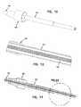
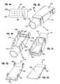
- FIG. 1is a perspective view of a main fiber optic cable and a protective transition member in position to be pre-applied on the main fiber optic cable;
- FIG. 2is a cross-sectional cut-away view of FIG. 1 ;
- FIG. 3is an enlarged detail view of FIG. 2 ;
- FIG. 4is a perspective view of the protective transition member of FIG. 1 pre-applied on the main fiber optic cable of FIG. 1 ;
- FIG. 5is a cross-sectional cut-away view of FIG. 4 ;
- FIG. 6is an enlarged detail view of FIG. 5 ;
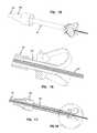
- FIG. 7is a perspective view of the pre-applied protective transition member and the main fiber optic cable of FIG. 4 with a reinforcing member in position to be pre-applied on the main fiber optic cable;
- FIG. 8is a cross-sectional cut-away view of FIG. 7 ;
- FIG. 9is an enlarged detail view of FIG. 8 ;
- FIG. 10is a perspective view of the reinforcing member of FIG. 7 pre-applied on the main fiber optic cable of FIG. 4 ;
- FIG. 11is a cross-sectional cut-away view of FIG. 10 ;
- FIG. 12is an enlarged detail view of FIG. 11 ;
- FIG. 13is a perspective view of the main fiber optic cable of FIG. 10 including longitudinal cuts that form strips at an end of a jacket of the main fiber optic cable;
- FIG. 14is a cross-sectional cut-away view of FIG. 13 ;
- FIG. 15is an enlarged detail view of FIG. 14 ;
- FIG. 16is a perspective view of the main fiber optic cable of FIG. 13 with the strips of the jacket held by a fixture thereby opening the end of the jacket of the main fiber optic cable;
- FIG. 17is a cross-sectional cut-away view of FIG. 16 ;
- FIG. 18is an enlarged detail view of FIG. 17 ;
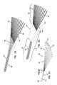
- FIG. 19is a perspective view of the main fiber optic cable of FIG. 16 with a pre-connectorized fiber optic cable assembly optically connected to optical fibers of the main fiber optic cable at a splice;
- FIG. 20is a cross-sectional cut-away view of FIG. 19 ;
- FIG. 21is an enlarged detail view of FIG. 20 ;
- FIG. 22is a perspective view of the main fiber optic cable and the pre-connectorized fiber optic cable assembly of FIG. 19 with the fixture of FIG. 16 removed and the strips at the end of the jacket of FIG. 13 closed over the splice of FIG. 19 ;
- FIG. 23is a cross-sectional cut-away view of FIG. 22 ;
- FIG. 24is an enlarged detail view of FIG. 23 ;
- FIG. 25is a perspective view of the main fiber optic cable and the pre-connectorized fiber optic cable assembly of FIG. 22 with the reinforcing member of FIG. 7 applied over the strips at the end of the jacket of FIG. 13 and the splice of FIG. 19 ;
- FIG. 26is a cross-sectional cut-away view of FIG. 25 ;
- FIG. 27is an enlarged detail view of FIG. 26 ;
- FIG. 28is a perspective view of the main fiber optic cable and the pre-connectorized fiber optic cable assembly of FIG. 25 with the protective transition member of FIG. 1 applied thereby forming a fiber optic cable assembly;
- FIG. 29is a cross-sectional cut-away view of FIG. 28 ;
- FIG. 30is an enlarged detail view of FIG. 29 ;
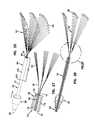
- FIG. 31is a perspective view of the pre-connectorized fiber optic cable assembly of FIG. 19 ;
- FIG. 32is an enlarged detail view of FIG. 31 illustrating a ribbonized portion and a jacketed portion with a strength reinforcement between the ribbonized portion and the jacketed portion;
- FIG. 33is the enlarged detail view of FIG. 32 but with a top half of the strength reinforcement removed;
- FIG. 34is a perspective view of the strength reinforcement of FIG. 32 ;
- FIG. 35is a top plan view of the strength reinforcement of FIG. 32 ;
- FIG. 36is a perspective view of a bottom half of the strength reinforcement of FIG. 32 ;
- FIG. 37is a perspective view of the top half of the strength reinforcement of FIG. 32 ;
- FIG. 38is a flowchart of a method of making the fiber optic cable assembly of FIG. 28 ;
- FIG. 39is a perspective view of another protective transition member adapted for another fiber optic cable assembly similar to the fiber optic cable assembly of FIG. 28 ;
- FIG. 40is a perspective view of a base of the protective transition member of FIG. 39 ;
- FIG. 41is another perspective view of the base of FIG. 40 ;
- FIG. 42is a perspective view of a cover of the protective transition member of FIG. 39 ;
- FIG. 43is another perspective view of the cover of FIG. 42 ;
- FIG. 44is a front elevation view of a cable support member of the protective transition member of FIG. 39 ;
- FIG. 45is an isometric view of another cable support member of the protective transition member of FIG. 39 ;
- FIG. 46is another perspective view of the cable support member of FIG. 45 ;
- FIG. 47is an isometric view of still another cable support member of the protective transition member of FIG. 39 ;
- FIG. 48is another perspective view of the cable support member of FIG. 47 ;
- FIG. 49is a perspective view of another fiber optic cable assembly similar to the fiber optic cable assembly of FIG. 28 but including a pre-connectorized fiber optic cable assembly with a multi-fiber connector;
- FIG. 50is a cross-sectional cut-away view of FIG. 49 ;
- FIG. 51is an enlarged detail view of FIG. 50 .
- the present disclosurerelates to fiber optic cable assemblies and methods of making them.
- a goal of the present disclosureis to increase efficiency in manufacturing fiber optic cable assemblies.
- pre-connectorized fiber optic cable assembliesare optically and mechanically joined to multi-fiber fiber optic cables.
- Examples of pre-connectorized fiber optic cable assemblies 52 , 152are illustrated at FIGS. 31 , 32 , and 50 , and an example of a multi-fiber fiber optic cable 54 (i.e., a main fiber optic cable) is illustrated at FIGS. 1-3 .
- One or more of the pre-connectorized fiber optic cable assemblies 52 , 152are joined to the main fiber optic cable 54 to form a fiber optic cable assembly 50 , 150 , illustrated at FIGS. 28-30 and 49 - 51 .
- a number of advantagescan be achieved when using the methods describe herein. They include:
- Connectorization of the pre-connectorized fiber optic cable assembly 52 , 152can be done independent of the main fiber optic cable 54 . This avoids having an often large and difficult to handle spool of the main fiber optic cable 54 present when the connectorization is performed. This allows making the pre-connectorized fiber optic cable assemblies 52 , 152 on higher speed equipment and/or making to stock. This also saves total manufacturing labor compared to breaking out long lengths of optical fiber.
- Optical performance of the optical jointcan be very good, particularly when using mass fusion splicing.
- Optical performance of the fiber optic cable assembly 50 , 150can also be enhanced by selecting optical fibers 56 , 156 (see FIGS. 31-33 and 51 ) for the pre-connectorized fiber optic cable assembly 52 , 152 that have optimal performance when matched with fiber optic connectors 58 , 158 that are specified.
- the fiber optic cable assembly 50 , 150can be made to a particular design using the same manufacturing process with the main fiber optic cable 54 being supplied by any of a number of different manufacturers and varying in specification.
- the fiber optic cable assembly 50 , 150can be made to a particular design using the same manufacturing process with optical fiber 72 of the main fiber optic cable 54 supplied by any of a number of different manufacturers and varying in specification.
- Fiber optic cables 60 , 160 of the pre-connectorized fiber optic cable assembly 52 , 152can have specifications separate from thin walled tubes 62 (e.g., buffer tubes) included within certain fiber optic cables (e.g., the main fiber optic cable 54 ).
- thin walled tubes 62e.g., buffer tubes
- the example fiber optic cable assembly 50 , 150can include a reinforcing member 64 , a mass fusion splice 66 , and a protective transition member 68 , 168 (see FIGS. 19-21 , 28 - 30 , and 39 ).
- the example main fiber optic cable 54includes an outer jacket 70 , a plurality of optical fibers 72 surrounded by the outer jacket 70 , and one or more strength members 74 surrounded by the outer jacket 70 (see FIG. 9 ).
- some or all of the optical fibers 72can be combined as ribbonized fibers (i.e., a fiber ribbon) 76 (see FIG. 24 ).
- the optical fibers 72are arranged into three of the fiber ribbons 76 .
- the main fiber optic cable 54can include the tubes 62 (e.g., loose buffer tubes), mentioned above (see FIG. 21 ).
- Each of the fiber ribbons 76can be positioned within one of the tubes 62 .
- the main fiber optic cable 54extends from a first end 78 to a second end 80 (see FIG. 1 ).
- the cable 54can be provided in varying lengths. To accommodate lengthy embodiments of the main fiber optic cable 54 and lengthy embodiments of the fiber optic cable assembly 50 , 150 , the main fiber optic cable 54 can be rolled up, wound about a storage spool, etc.
- the optical fibers 72 of the main fiber optic cable 54have ends 82 positioned adjacent the first end 78 of the main fiber optic cable 54 (see FIG. 5 ).
- the ends 82 of the optical fibers 72can be spaced from the first end 78 of the main fiber optic cable 54 .
- the ends 82 of the optical fibers 72can be positioned within the outer jacket 70 of the main fiber optic cable 54 .
- the optical fibers 72 of the main fiber optic cable 54can be positioned within the tubes 62 of the main fiber optic cable 54 .
- the tubes 62can thereby enclose one or more of the optical fibers 72 (see FIG. 3 ).
- the tubes 62are positioned within the outer jacket 70 of the main fiber optic cable 54 .
- a typical example of the tube 62has an outer diameter of 3 mm and a wall thickness of 0.5 mm.
- the typical thin wall tube 62can be broken out of the outer jacket 70 of the main fiber optic cable 54 or extend beyond the ends 78 , 80 of the main fiber optic cable 54 .
- the thin wall tube 62can be routed to various optical components separate from the main fiber optic cable 54 .
- the typical thin wall tube 62can be relatively stiff, hard, and/or inflexible.
- the thin wall tube 62may not be ideal for routing the optical fibers 72 , within the thin wall tube 62 , to and/or through the various optical components.
- the thin wall tubes 62can have characteristics specified that are beneficial to their application within the main fiber optic cable 54 . These characteristics can include cost, manufacturing characteristics (e.g., extrudability), stiffness, strength, environmental durability, frictional characteristics, heat resistance, fire resistance, etc. The characteristics that are beneficial to the application of the tubes 62 within the main fiber optic cable 54 are not always beneficial for application of the tube 62 external from the main fiber optic cable 54 .
- the tube 62can be any tube, sheathing, conduit, etc., used within the main fiber optic cable 54 , that is positioned around one or more of the optical fibers 72 .
- the example pre-connectorized fiber optic cable assemblies 52 , 152include a plurality of the optical fibers 56 , 156 and one or more of the fiber optic connectors 58 , 158 (see FIGS. 31 and 50 ).
- the fiber optic connectors 58 , 158can include, in any combination and quantity, an LC connector, an SC connector, an MT connector, an LX connector, and other types of single fiber and/or multi-fiber fiber optic connectors. As illustrated at the figures, the fiber optic connector 58 depicts a single-fiber fiber optic connector and the fiber optic connector 158 depicts a multi-fiber fiber optic connector.
- the optical fibers 56 , 156 of the pre-connectorized fiber optic cable assembly 52 , 152have distal ends 84 and proximal ends 86 (see FIG. 31 ).
- the optical fibers 56 , 156 and/or the fiber optic cables 60 , 160 of the pre-connectorized fiber optic cable assembly 52 , 152can included characteristics specified for a given application (e.g., routing to and/or through the various optical components).
- the characteristics of a fiber jacket 88 , 288 of the fiber optic cable 60 , 160can be specified separately from the characteristics of the tube 62 of the main fiber optic cable 54 .
- the characteristics of the optical fibers 56 , 156 within the fiber optic cable 60 , 160can be specified separately from the characteristics of the optical fibers 72 of the main fiber optic cable 54 .
- the characteristics of the fiber optic cable 60 , 160can be specified separately from characteristics of the tube 62 and its contents.
- the optical fibers 56 and the fiber optic cables 60can be flexible and adapted to route to and/or through the various optical components.
- the fiber optic cable 60 , 160can be specified for strength requirements of a given application.
- the fiber optic cable 60 , 160can include one or more strength member 96 .
- the fiber jacket 88 , 288 of the fiber optic cable 60 , 160can be a reinforced fiber jacket.
- the fiber jacket 88 , 288can enclose one or more of the optical fibers 56 , 156 .
- the distal ends 84 of the optical fibers 56 , 156 of the pre-connectorized fiber optic cable assembly 52 , 152are terminated by the fiber optic connectors 58 , 158 , and the proximal ends 86 are adapted for mass fusion splicing. More than one distal end 84 can be terminated by the multi-fiber fiber optic connector 158 (e.g., the MT connector).
- the fiber optic cables 60 , 160can be single fiber cables or multi-fiber cables. As illustrated at the figures, the fiber optic cable 60 depicts a single-fiber cable, and the fiber optic cable 160 depicts a multi-fiber cable.
- the pre-connectorized fiber optic cable assembly 52 , 152can include a plurality of the single fiber cables 60 and/or the multi-fiber cables 160 .
- the fiber jacket 88 , 288can be a single fiber jacket or a multi-fiber jacket. As illustrated at the figures, the fiber jacket 88 depicts a single-fiber jacket, and the fiber jacket 288 depicts a multi-fiber jacket.
- Each of the optical fibers 56 of the pre-connectorized fiber optic cable assembly 52can be positioned within the single-fiber jacket 88 of one of the single fiber cables 60 .
- the optical fibers 156 of the pre-connectorized fiber optic cable assembly 152can be collectively positioned within the multi-fiber jacket 288 of the fiber optic cable 160 .
- the pre-connectorized fiber optic cable assembly 52 , 152can include a ribbonized portion 92 with no fiber jacket 88 , 288 positioned around the optical fibers 56 , 156 and also include a jacketed portion 90 (see FIG. 32 ).
- the pre-connectorized fiber optic cable assembly 52 , 152can include a strength reinforcement (e.g., a fanout) 94 , 294 between the ribbonized portion 92 and the jacketed portion 90 (see FIGS. 32 and 51 ).
- the jackets 88 , 288 of the cables 60 , 160can be higher in mechanical strength and/or more robust than the tubes 62 of the main fiber optic cable 54 .
- the cable 60 , 160can include one or more of the strength members 96 (see FIG. 33 ).
- the strength members 96 and/or the jacket 88 , 288 of the cable 60 , 160can be anchored to and/or within the strength reinforcement 94 , 294 of the pre-connectorized fiber optic cable assembly 52 ,
- the reinforcing member 64extends from a first end 98 to a second end 100 (see FIG. 7 ) and is positioned around a longitudinal portion 102 of the outer jacket 70 of the main fiber optic cable 54 when assembled (see FIG. 25 ).
- the first end 98 of the reinforcing member 64is positioned nearer to the first end 78 of the main fiber optic cable 54 than the second end 100
- the second end 100is positioned nearer to the second end 80 of the main fiber optic cable 54 than the first end 98 .
- the first end 98 of the reinforcing member 64can be positioned at the first end 78 of the main fiber optic cable 54 .
- the reinforcing member 64can include a heat shrink tube 104 (see FIG. 25 ).
- the heat shrink tube 104can be a thick-walled heat shrink tube.
- the mass fusion splice 66optically joins the proximal ends 86 of the optical fibers 56 , 156 of the pre-connectorized fiber optic cable assembly 52 , 152 to the end 82 of the optical fibers 72 of the main fiber optic cable 54 (see FIGS. 20 and 51 ).
- a mechanical splice or another type of splicecould be used in place of the mass fusion splice 66 .
- the mass fusion splice 66can include a UV re-coating 106 (see FIG. 20 ).
- the mass fusion splice 66can be positioned within the reinforcing member 64 and within the outer jacket 70 of the main fiber optic cable 54 (see FIGS. 27 and 51 ).
- mass fusion splicingis given at U.S. Pat. No. 5,588,082, issued Dec. 24, 1996 to Whitesmith, and is hereby incorporated by reference in its entirety.
- Other mass fusion splicing techniquesare also known in the art.
- Certain mass fusion splicing techniquesinclude firing a preparation arc across ends of optical fibers for the purpose of cleaning the ends.
- Certain mass fusion splicing techniquesinclude simultaneously firing a fusion arc and moving together the ends of the optical fibers being spliced.
- Typical mass fusion splicesindividually join the ends of corresponding optical fibers. When mass fusion splicing a multi-fiber ribbon to individual fibers, a separate optical splice is typically formed between each of the corresponding individual fiber ends.
- a separate optical spliceis typically formed between each of the corresponding individual fiber ends.
- the optical splicescan be generally cylindrical in shape and match a diameter of the corresponding optical fibers.
- the longitudinal portion 102 of the outer jacket 70 of the main fiber optic cable 54can include at least one cut 108 extending from an end 110 of the outer jacket 70 (see FIG. 22 ).
- the cut 108 or cuts 108allows access to within the outer jacket 70 for forming the mass fusion splice 66 when the fiber optic cable assembly 50 , 150 is being manufactured.
- four longitudinal cuts 108are used to open the end 110 of the outer jacket 70 .
- the four longitudinal cuts 108can be equally spaced circumferentially about the outer jacket 70 , as shown.
- the reinforcing member 64can be pre-positioned over the main fiber optic cable 54 , as illustrated at FIGS. 10-12 .
- the reinforcing member 64can be pre-positioned before the longitudinal cuts 108 are made on the outer jacket 70 .
- the reinforcing member 64can be positioned over the longitudinal cuts 108 .
- a length of the reinforcing member 64is preferably as long as or longer than a length of the longitudinal cuts 108 .
- the reinforcing member 64generally coincides with (i.e., is generally coextensive with) the longitudinal cuts 108 when the fiber optic cable assembly 50 , 150 is finished.
- the reinforcing member 64closes or helps to close the longitudinal portion 102 of the outer jacket 70 of the main fiber optic cable 54 .
- the protective transition member 68can be pre-positioned over the main fiber optic cable 54 , as illustrated at FIGS. 4-6 .
- the protective transition member 68can be pre-positioned before the longitudinal cuts 108 are made on the outer jacket 70 .
- the protective transition member 68can be positioned over the first end 78 of the main fiber optic cable 54 (see FIG. 25-27 compared with FIGS. 28-30 ).
- the illustrated protective transition member 68is an example protective transition member and includes a tapered boot portion and a cylindrical portion.
- protective transition members 68can include features that individually conform to the jackets 88 , 288 of one or more of the cables 60 .
- the protective transition member 68can include special molded shapes adapted for various applications.
- the protective transition member 68can be made of a rubber or rubber-like material, a relatively soft material, or a relatively hard material.
- the protective transition member 68can provide strain-relief to one or more of the cables 60 .
- the strength reinforcements 94can be housed within the protective transition member 68 . As illustrated, the strength reinforcements 94 are housed within the cylindrical portion of the protective transition member 68 . As illustrated, the tapered boot portion tapers inwardly to match an outside diameter of the reinforcing member 64 .
- the protective transition member 68is positioned over the first end 78 of the main fiber optic cable 54 and is positioned around a portion 112 of the pre-connectorized fiber optic cable assembly 52 (see FIGS. 30 and 32 ).
- An interior 114 of the protective transition member 68is at least partially filled with a solidified filling material 116 (see FIG. 30 ).
- the solidified filling material 116can be an epoxy.
- the single-fiber jackets 88 of the single fiber cables 60can be secured to the main fiber optic cable 54 by the solidified filling material 116 .
- the strength members 96 of the single-fiber cables 60can be secured to the main fiber optic cable 54 by the solidified filling material 116 .
- the multi-fiber jacket 288 of the multi-fiber cables 160can be secured to the main fiber optic cable 54 by the solidified filling material 116 .
- the strength members 96 of the multi-fiber cable 160can be secured to the main fiber optic cable 54 by the solidified filling material 116 .
- the strength members 96can be directly secured to the solidified filling material 116 .
- the strength members 96can be indirectly secured to the solidified filling material 116 (e.g., via the strength reinforcement 94 , 294 ).
- the strength members 74 of the main fiber optic cable 54can be secured by the solidified filling material 116 .
- a solidified filling material 118can at least partially fill an interior 120 of the longitudinal portion 102 of the outer jacket 70 that is positioned within the reinforcing member 64 (see FIG. 27 ).
- the solidified filling material 118can be polyurethane foam. Before injecting the filling material 118 into the interior 120 , various tubes, water swellable yarns, and central member coatings are preferably locally removed to provide clearance for better flow of the filling material 118 . The better flow allows the filling material 118 to flow around the exposed coated fibers 72 and the strength members 74 without voids in the filling material 118 .
- the mass fusion splice 66can be positioned within the solidified filling material 118 .
- the strength members 74 of the main fiber optic cable 54can be secured by the solidified filling material 118 .
- the solidified filling material 116is stiffer (i.e., harder) than the solidified filling material 118 . In other embodiments, the solidified filling materials 116 and 118 are the same material. In certain embodiments, the solidified filling material 116 is a relatively hard material (e.g., hard epoxy) and the protective transition member 68 is also a relatively hard material (e.g., a thermo-set plastic). In other embodiments, the solidified filling material 116 is a relatively soft material (e.g., the polyurethane foam) and the protective transition member 68 is the relatively hard material. In still other embodiments, the solidified filling material 116 is the relatively hard material and the protective transition member 68 is a relatively soft material (e.g., a rubber).
- the solidified filling material 116is a relatively hard material and the protective transition member 68 is a relatively soft material (e.g., a rubber).
- the optical fibers 72 of the main fiber optic cable 54can be a first type of optical fiber, and at least one of the optical fibers 56 , 156 of the pre-connectorized fiber optic cable assembly 52 , 152 can be a second type of optical fiber.
- the first type of optical fibercan be lower in cost than the second type of optical fiber.
- the second type of optical fibercan be performance matched to the fiber optic connector 58 , 158 terminating the second type of optical fibers.
- the present disclosurealso relates to a method of making the fiber optic cable assembly 50 , 150 .
- the methodincludes selecting and providing the main fiber optic cable 54 , selecting and providing the pre-connectorized fiber optic cable assembly 52 , 152 , mass fusion splicing the proximal ends 86 of the optical fibers 56 , 156 of the pre-connectorized fiber optic cable assembly 52 , 152 to the end 82 of the optical fibers 72 of the main fiber optic cable 54 thereby forming the mass fusion splice 66 , positioning the mass fusion splice 66 within the outer jacket 70 of the main fiber optic cable 54 , applying the reinforcing member 64 to the outer jacket 70 of the main fiber optic cable 54 with the reinforcing member 64 positioned over the mass fusion splice 66 , and applying the protective transition member 68 to the main fiber optic cable 54 and the pre-connectorized fiber optic cable assembly 52 , 152 .
- the methodcan further include pre-applying the protective transition member 68 to the main fiber optic cable 54 and pre-applying the reinforcing member 64 to the main fiber optic cable 54 .
- the methodcan further include opening the end 110 of the outer jacket 70 of the main fiber optic cable 54 before forming the mass fusion splice 66 and closing the end 110 after forming the mass fusion splice 66 .
- the methodcan further include UV recoating the mass fusion splice 66 after forming the mass fusion splice 66 .
- the methodcan further include removing various tubes, water swellable yarns, and central member coatings from within the longitudinal portion 102 of the outer jacket 70 of the main fiber optic cable 54 .
- the methodcan further include filling or partially filling the interior 120 of the longitudinal portion 102 of the outer jacket 70 of the main fiber optic cable 54 with the solidified filling material 118 .
- the methodcan further include filling or partially filling the interior 114 of the protective transition member 68 with the solidified filling material 116 .
- Selecting and providing the main fiber optic cable 54can be done independently of selecting and providing the pre-connectorized fiber optic cable assembly 52 , 152 .
- a sequence of an example methodis illustrated sequentially in the figures beginning with the main fiber optic cable 54 , shown at FIGS. 1-3 , and ending with the example fiber optic cable assembly 50 , shown at FIGS. 28-30 .
- FIG. 39illustrates the other example protective transition member 168 .
- the protective transition member 168is similar to the protective transition member 68 , described above. The similarities include: 1) the protective transition member 168 or a base 176 of the protective transition member 168 can be pre-positioned over the main fiber optic cable 54 ; 2) the protective transition member 168 or the base 176 of the protective transition member 168 can be pre-positioned before the longitudinal cuts 108 are made on the outer jacket 70 ; 3) the protective transition member 168 can be positioned over the first end 78 of the main fiber optic cable 54 after the splice 66 is made between the ends 86 of the optical fibers 56 , 156 and the ends 82 of the optical fibers 72 ; 4) the protective transition member 168 can be positioned over the first end 78 of the main fiber optic cable 54 after the reinforcing member 64 is positioned over the longitudinal cuts 108 ; 5) the protective transition member 168 can be positioned around the portion 112 of the pre-connectorized fiber optic cable assembly 52 , 152
- the protective transition member 168can be at least partially filled with the solidifying filling material 116 , 118 ; and 7) the attachments/connections/securement between the solidified filing materials 116 , 118 , the strength members 74 , 96 , the cable 54 , and the pre-connectorized fiber optic cable assemblies 52 , 152 .
- the protective transition member 168can include a housing portion 170 and a cylindrical portion 172 .
- the strength reinforcements 94 , 294can be housed within the housing portion 170 .
- An inner diameter 174 of the cylindrical portion 172can be sized to fit over the reinforcing member 64 .
- the inner diameter 174can be sized to fit over the jacket 70 of the main fiber optic cable 54 .
- the cylindrical portion 172can be replaced with a non-cylindrical portion, and the inner diameter 174 can be replaced with a shape that matches the non-cylindrical cable.
- the cylindrical portion 172is preferably positioned adjacent and around the first end 78 of the main fiber optic cable 54 , and the cylindrical portion 172 overlaps a portion of the cable 54 .
- the housing portion 170is preferably positioned beyond the first end 78 of the main fiber optic cable 54 .
- the protective transition member 168is made of a Celanex® thermoplastic polyester available from Ticona of Summit, N.J., USA.
- Celanex® 3216that is flame retardant and includes 15% Glass-fiber, is used.
- the protective transition member 168includes the base 176 (see FIGS. 40 and 41 ), a cover 178 (see FIGS. 42 and 43 ), and a selected cable support member 180 , 180 ′, 280 , 380 (see FIGS. 32 and 44 - 48 ).
- the base 176includes one or more attachment members 182 , the cylindrical portion 172 , a cavity 184 , and a retaining structure 186 .
- the cover 178includes a lid 188 , one or more attachment members 190 , and a retainer 192 .
- the protective transition member 168is assembled by inserting one of the cable support members (e.g., cable support blocks) 180 , 180 ′, 280 , 380 into the retaining structure 186 of the base 176 and attaching the cover 178 to the base 176 .
- the cavity 184 , the lid 188 , and the cable support member 180 , 180 ′, 280 , 380define boundaries for the interior 214 of the protective transition member 168 .
- the attachment members 182 of the base 176are channel-like and receive the attachment members 190 of the cover 178 to attach the cover 178 to the base 176 .
- the retaining structure 186 of the base 176includes a pair of channels 194 that captures flanges 196 of the cable support block 180 , 180 ′, 280 , 380 when the flanges 196 are slid into the channels 194 .
- a first end 198 of the cable support member 180 , 180 ′, 280 , 380abuts a stop 200 of the base 176
- the retainer 192 of the cover 178abuts a second end 202 of the cable support block 180 , 180 ′, 280 , 380 when the cover 178 is attached to the base 176 .
- the cable support member 180 , 180 ′, 280 , 380includes a plurality of holes 206 .
- the holes 206are cylindrical and/or oblong.
- the holes 206can be arranged in one or more rows 208 of holes 206 (see FIG. 44 ).
- three rows 208 of six holes 206each are arranged in a rectangular grid.
- three rows 208 of twelve holes 206each are arranged in a rectangular grid.
- the holes 206can be arranged in other arrangements.
- the number of the rows 208 in the cable support member 180 , 180 ′, 280 , 380is equal to the number of the fiber ribbons 76 in the main fiber optic cable 54 .
- the optical fibers 72 of a given fiber ribbon 76 of the main fiber optic cable 54correspond with a given row 208 of the cable support member 180 , 180 ′, 280 , 380 (i.e., the fibers 72 of the given ribbonized fibers 76 pass through the holes 206 of the given row 208 ).
- a quantity of the holes 206 in a given row 208 of the cable support block 180 , 180 ′, 280is equal to a quantity of the optical fibers 72 of each of the fiber ribbons 76 of the main fiber optic cable 54 .
- the holes 206can each receive one of the jackets 88 , 288 of the fiber optic cables 60 , 160 of the pre-connectorized fiber optic cable assemblies 52 , 152 .
- the cable support member 180 , 180 ′, 280 , 380can be preassembled on the pre-connectorized fiber optic cable assembly 52 , 152 or assemblies 52 , 152 (e.g., before the fiber optic connectors 58 , 158 are attached and/or before the cable assembly 52 , 152 is joined to the main cable 54 ).
- the cable support member 180 , 180 ′, 280 , 380can be positioned between the fiber optic connectors 58 , 158 and the strength reinforcements 94 , 294 (see FIG. 32 ).
- a single one of the optical fibers 56can pass through each of the corresponding holes 206 .
- a plurality of the optical fibers 156can pass through each of the corresponding holes 206 .
- the holes 206can be non-cylindrical.
- certain holes 206can hold a plurality of the optical fibers 156 and other holes 206 can hold a single one of the optical fibers 56 .
- the solidifying filing materials 116 , 118can be injected and/or applied into the interior 214 of the protective transition member 168 when the cover 178 is removed from the base 176 .
- the solidifying filing material 118can be injected and/or applied into the interior 120 of the longitudinal portion 102 of the outer jacket 70 via the base 176 when the cover 178 is removed from the base 176 .
- the cover 178can be attached to the base 176 after the filing materials 116 , 118 are applied and/or injected into the interiors 120 and/or 214 .
- the protective transition member 68 , 168can include the solidified filling material 116 .
- the solidified filling material 116can conform to the jackets 88 , 288 of one or more of the cables 60 , 160 .
- Other protective transition memberscan include features that individually conform to the jackets 88 , 288 of one or more of the cables 60 , 160 .
- FIGS. 45-48illustrate the cable support members 280 and 380 that are adapted to be mounted between the base 176 and the cover 178 of the protective transition member 168 .
- the cable support members 180 , 180 ′, 280 , and 380are interchangeable within the protective transition member 168 .
- the protective transition member 168can thereby be customized to attach to and/or conform to various quantities and types of fiber optic cables including the fiber optic cables 60 , 160 .
- various cable support members including the cable support members 180 , 180 ′, 280 , and 380can be inserted between the same base 176 and cover 178 , a variety of fiber optic cable assemblies with a variety of quantities and types of fiber optic cables can be made using the same base 176 and cover 178 .
- the cable support members 180 , 180 ′, 280 , and 380can be made of a flexible and/or resilient material such as rubber.
- the cable support members 180 , 180 ′, 280 , and 380can include one or more strain relief members 284 , 384 (see FIGS. 45-48 ).
- the strain relief members 284 , 384can provide strain-relief to the fiber optic cables 60 , 160 .
- the strain relief members 284 , 384can be made of a flexible and/or resilient material such as rubber.
- the strain relief member 284is adapted to provide strain-relief to a single fiber cable such as the fiber optic cable 60
- the strain relief member 384is adapted to provide strain-relief to a multi-fiber cable such as the fiber optic cable 160 .
- FIGS. 49-51illustrate the fiber optic cable assembly 150 .
- the fiber optic cable assembly 150is similar to the fiber optic cable assembly 50 but includes the multi-fiber cable 160 , included within the pre-connectorized fiber optic cable assembly 152 , along with the single fiber cables 60 , included within the pre-connectorized fiber optic cable assembly 52 .
- any combination of fiber optic cable typescan be included within a pre-connectorized fiber optic cable assembly (e.g., several different types of single fiber cables and one or more types of multi-fiber cable can be included together in the same pre-connectorized fiber optic cable assembly).
- the optical fibers 72 of a given fiber ribbon 76 of the main fiber optic cable 54can be joined (e.g., mass fusion spliced) to one or more of the ribbonized portions 92 of one or more of the pre-connectorized fiber optic cable assemblies 52 and/or 152 .
- the optical fibers 56 , 156 of a given ribbonized portion 92 of the pre-connectorized fiber optic cable assembly 52 or 152can be joined (e.g., mass fusion spliced) to one or more of the fiber ribbons 76 or portions of the fiber ribbons 76 of the main fiber optic cable 54 .
- FIG. 51illustrates a cable support member 180 ′′.
- the cable support member 180 ′′is similar to the cable support members 180 , 180 ′, 280 , and 380 but is adapted to mount to the protective transition member 68 of the fiber optic cable assembly 50 , 150 .
- the cable support member 180 ′′can be preassembled to the pre-connectorized fiber optic cable assemblies 52 and/or 152 .
- various cable support memberscan be made for the protective transition member 68 .
- the various cable support members for the protective transition member 68allows various fiber optic cable assemblies to be made by switching in and out various pre-connectorized fiber optic cable assemblies and cable support members.
- the filing materials 116 , 118can be included in the fiber optic cable assembly 150 , as they can be included in the fiber optic cable assembly 50 .
- FIGS. 49-51do not illustrate the filling materials 116 , 118 .
Landscapes
- Physics & Mathematics (AREA)
- General Physics & Mathematics (AREA)
- Optics & Photonics (AREA)
- Engineering & Computer Science (AREA)
- Plasma & Fusion (AREA)
- Mechanical Coupling Of Light Guides (AREA)
Abstract
Description
Claims (29)
Priority Applications (1)
| Application Number | Priority Date | Filing Date | Title |
|---|---|---|---|
| US13/087,807US8457461B2 (en) | 2010-04-16 | 2011-04-15 | Fiber optic cable assembly and method of making the same |
Applications Claiming Priority (2)
| Application Number | Priority Date | Filing Date | Title |
|---|---|---|---|
| US32513310P | 2010-04-16 | 2010-04-16 | |
| US13/087,807US8457461B2 (en) | 2010-04-16 | 2011-04-15 | Fiber optic cable assembly and method of making the same |
Publications (2)
| Publication Number | Publication Date |
|---|---|
| US20110262084A1 US20110262084A1 (en) | 2011-10-27 |
| US8457461B2true US8457461B2 (en) | 2013-06-04 |
Family
ID=44799344
Family Applications (1)
| Application Number | Title | Priority Date | Filing Date |
|---|---|---|---|
| US13/087,807Expired - Fee RelatedUS8457461B2 (en) | 2010-04-16 | 2011-04-15 | Fiber optic cable assembly and method of making the same |
Country Status (3)
| Country | Link |
|---|---|
| US (1) | US8457461B2 (en) |
| EP (1) | EP2558892A2 (en) |
| WO (1) | WO2011130642A2 (en) |
Cited By (23)
| Publication number | Priority date | Publication date | Assignee | Title |
|---|---|---|---|---|
| US20120201500A1 (en)* | 2009-10-19 | 2012-08-09 | Sumitomo Electric Industries, Ltd. | Spliced opitcal cable assembly |
| US20130330052A1 (en)* | 2012-06-11 | 2013-12-12 | Tyco Electronics Corporation | Universal fan-out device |
| US20140133822A1 (en)* | 2012-11-13 | 2014-05-15 | Cesar Alejandro de los Santos Campos | Rotatable furcation assembly |
| US9140872B2 (en) | 2013-09-17 | 2015-09-22 | Panduit Corp. | Hydra cable assembly and components thereof |
| US9455063B2 (en) | 2013-09-26 | 2016-09-27 | Apple Inc. | Cable structures with localized foam strain reliefs and systems and methods for making the same |
| US9500830B2 (en) | 2012-09-28 | 2016-11-22 | Commscope Technologies Llc | Splice-on cable breakout assembly |
| US9575277B2 (en)* | 2015-01-15 | 2017-02-21 | Raycap, S.A. | Fiber optic cable breakout assembly |
| US9640986B2 (en) | 2013-10-23 | 2017-05-02 | Raycap Intellectual Property Ltd. | Cable breakout assembly |
| US10133019B2 (en) | 2013-06-07 | 2018-11-20 | Commscope Technologies Llc | Telecommunications connection device |
| US10181717B2 (en) | 2010-07-13 | 2019-01-15 | Raycap S.A. | Overvoltage protection system for wireless communication systems |
| US10353164B2 (en) | 2017-06-27 | 2019-07-16 | Afl Telecommunications Llc | Fiber optic transition assemblies |
| US10429604B2 (en) | 2015-11-03 | 2019-10-01 | Raycap S.A. | Modular fiber optic cable splitter |
| US10656360B2 (en)* | 2018-01-23 | 2020-05-19 | Panduit Corp. | Epoxy transitions for optical fiber modules |
| US10802237B2 (en) | 2015-11-03 | 2020-10-13 | Raycap S.A. | Fiber optic cable management system |
| US10812664B2 (en) | 2017-01-20 | 2020-10-20 | Raycap S.A. | Power transmission system for wireless communication systems |
| US10971928B2 (en) | 2018-08-28 | 2021-04-06 | Raycap Ip Assets Ltd | Integrated overvoltage protection and monitoring system |
| US20220035109A1 (en)* | 2020-07-29 | 2022-02-03 | Google Llc | Cable Connection Structure For Fiber Optic Hardware Management |
| US11251608B2 (en) | 2010-07-13 | 2022-02-15 | Raycap S.A. | Overvoltage protection system for wireless communication systems |
| US20220163722A1 (en)* | 2020-11-24 | 2022-05-26 | Corning Research & Development Coorporation | Multi-fiber splice protector with compact splice-on furcation housing |
| US11378766B2 (en) | 2018-11-06 | 2022-07-05 | Sumitomo Electric Industries, Ltd. | Optical fiber cable |
| US11677164B2 (en) | 2019-09-25 | 2023-06-13 | Raycap Ip Assets Ltd | Hybrid antenna distribution unit |
| US12237134B2 (en) | 2021-12-28 | 2025-02-25 | Raycap Ip Assets Ltd | Circuit protection for hybrid antenna distribution units |
| US12282201B2 (en) | 2022-02-15 | 2025-04-22 | Google Llc | Splicing tray utilized in fiber optic patch panel assembly for fiber optic cable connection management |
Families Citing this family (12)
| Publication number | Priority date | Publication date | Assignee | Title |
|---|---|---|---|---|
| US8737786B1 (en)* | 2013-02-14 | 2014-05-27 | Corning Cable Systems Llc | Fiber optic cable assembly |
| US10054753B2 (en)* | 2014-10-27 | 2018-08-21 | Commscope Technologies Llc | Fiber optic cable with flexible conduit |
| AU2015207954C1 (en) | 2015-07-31 | 2022-05-05 | Adc Communications (Australia) Pty Limited | Cable breakout assembly |
| EP3403125B1 (en) | 2016-03-18 | 2021-07-14 | Commscope Technologies LLC | Fiber-optic cable fanout conduit arrangement and method for organizing optical fibers |
| US10890730B2 (en) | 2016-08-31 | 2021-01-12 | Commscope Technologies Llc | Fiber optic cable clamp and clamp assembly |
| US10914909B2 (en) | 2016-10-13 | 2021-02-09 | Commscope Technologies Llc | Fiber optic breakout transition assembly incorporating epoxy plug and cable strain relief |
| US10018783B2 (en)* | 2016-12-05 | 2018-07-10 | Mellanox Technologies, Ltd. | Fan-out joint for fiberoptic cables |
| CN110622051A (en) | 2017-05-08 | 2019-12-27 | 康普技术有限责任公司 | Optical fiber branch transition assembly |
| JP6603292B2 (en)* | 2017-11-08 | 2019-11-06 | 株式会社フジクラ | Optical cable branch and method for manufacturing optical cable branch |
| EP3959556A1 (en)* | 2019-04-22 | 2022-03-02 | Corning Research & Development Corporation | Fiber optic cable assembly with furcation and method of making same |
| EP3997500A4 (en)* | 2019-07-08 | 2023-07-26 | CommScope Technologies LLC | TERMINATION OF A CABLE ASSEMBLY WITH CONNECTORIZED PIGTAILS |
| WO2024015133A1 (en)* | 2022-07-15 | 2024-01-18 | Afl Telecommunications Llc | Adaptive cable assembly and method for construction |
Citations (37)
| Publication number | Priority date | Publication date | Assignee | Title |
|---|---|---|---|---|
| US5185840A (en) | 1991-05-06 | 1993-02-09 | Computer Crafts, Inc. | Branching method for a multi-fiber fiberoptic cable |
| US5253315A (en) | 1990-12-24 | 1993-10-12 | Fentress Vernon A | Method and apparatus for installing a fiber optic cable by capture of a coupling nut or coupling nut assembly |
| US5491766A (en) | 1993-04-16 | 1996-02-13 | Raychem Corporation | Bonding assembly for fiber optic cable and associated method |
| US5588082A (en) | 1994-09-20 | 1996-12-24 | Whitesmith; Peter J. | Optical cable fusion splice |
| US5915055A (en)* | 1997-06-30 | 1999-06-22 | Siecor Corporation | Method and apparatus for connectorizing fiber optic cable |
| US5925462A (en) | 1992-06-17 | 1999-07-20 | Ppg Industries Ohio, Inc. | Aqueous coating compositions for glass fibers, fiber strands coated with such compositions and optical fiber cable assemblies including such fiber strands |
| JP2001330765A (en) | 2000-05-24 | 2001-11-30 | Tsushin Kogyo Kk | Optical fiber cable |
| US6379054B2 (en) | 1998-07-01 | 2002-04-30 | Corning Cable Systems Llc | Field installable multifiber connector |
| US6389214B1 (en) | 2001-05-17 | 2002-05-14 | 3M Innovative Properties Company | Furcation apparatus for optical fibers |
| US6438300B1 (en)* | 1999-09-21 | 2002-08-20 | Tycom (Us) Inc. | Fiber retaining system |
| US6439780B1 (en) | 2000-08-31 | 2002-08-27 | Corning Cable Systems Llc | Field-installable fiber optic ribbon connector and installation tool |
| US20030179980A1 (en) | 2002-03-19 | 2003-09-25 | Baechtle David R. | Optical circuit with ribbonization |
| US6771861B2 (en) | 2002-05-07 | 2004-08-03 | Corning Cable Systems Llc | High performance, flexible optical fiber furcation |
| US7104702B2 (en) | 2004-03-24 | 2006-09-12 | Corning Cable Systems Llc | Field installable optical fiber connector |
| US7192194B2 (en) | 2005-01-13 | 2007-03-20 | Frank Giotto | Universal adapter for fiber optic connectors |
| US7216512B2 (en) | 2003-10-31 | 2007-05-15 | Corning Cable Systems, Llc | Method of making an optical fiber by laser cleaving |
| US7228047B1 (en) | 2006-06-16 | 2007-06-05 | Molex Incorporated | Breakout and connector assemblies for use with high count fiber optic cables |
| US7264410B1 (en) | 2006-03-16 | 2007-09-04 | Corning Cable Systems Llc | Dual function splice component for mechanical splice connector |
| US7264401B2 (en) | 2004-05-28 | 2007-09-04 | Corning Cable Systems Llc | Panel-mountable optical fiber splice |
| US7270487B2 (en) | 2004-04-30 | 2007-09-18 | Corning Cable Systems Llc | Field installable optical fiber connector |
| US7270485B1 (en) | 2006-06-23 | 2007-09-18 | Carlyle, Inc. | Device for furcating fiber optic cables |
| US7281859B2 (en) | 2004-11-29 | 2007-10-16 | Corning Cable Systems Llc | Optical fiber connector and method of assembly |
| US7329049B2 (en) | 2005-12-27 | 2008-02-12 | Corning Cable Systems Llc | Splice connector for verifying an acceptable splice termination |
| US20080138026A1 (en) | 2006-12-08 | 2008-06-12 | Yow Charles A | Furcation tubing and fanout furcation kit |
| US20080170833A1 (en)* | 2007-01-12 | 2008-07-17 | Guy Castonguay | Fiber optic local convergence points for multiple dwelling units |
| US7440667B2 (en) | 2006-08-31 | 2008-10-21 | Tyco Electronics Corporation | Duct closures and methods of sealing ducts using the same |
| US20090022457A1 (en) | 2007-07-16 | 2009-01-22 | De Jong Michael | Fusion-splice fiber optic connectors and related tools |
| US20090060421A1 (en) | 2007-03-16 | 2009-03-05 | 3M Innovative Properties Company | Optical fiber cable inlet device |
| US7572064B2 (en) | 2006-07-24 | 2009-08-11 | Corning Cable Systems Llc | Optical fiber mechanical splice connector |
| US7594764B2 (en) | 2004-03-29 | 2009-09-29 | Corning Cable Systems Llc | Field-installable fusion spliced fiber optic connector kits and methods therefor |
| KR20090116650A (en) | 2008-05-06 | 2009-11-11 | 드라카 콤텍 비.브이. | Single mode fiber |
| US7658553B2 (en) | 2006-03-14 | 2010-02-09 | Corning Cable Systems Llc | Mechanical splice connector with sequential splice and strain relief |
| US20100142905A1 (en) | 2006-01-26 | 2010-06-10 | Billman Bradley S | Installation tool with integrated visual fault indicator for field-installable mechanical splice connector |
| US20100183265A1 (en) | 2009-01-19 | 2010-07-22 | Barnes Brandon A | Termination system for fiber optic connection |
| US20100303416A1 (en) | 2009-05-29 | 2010-12-02 | Danley Jeffrey D | Laser-Shaped Optical Fibers Along with Optical Assemblies and Methods Therefor |
| US7945136B2 (en) | 2009-06-19 | 2011-05-17 | Corning Cable Systems Llc | Mounting of fiber optic cable assemblies within fiber optic shelf assemblies |
| US8333519B2 (en)* | 2008-08-29 | 2012-12-18 | Adc Telecommunications, Inc. | Splice of fiber optic cables |
- 2011
- 2011-04-15USUS13/087,807patent/US8457461B2/ennot_activeExpired - Fee Related
- 2011-04-15WOPCT/US2011/032704patent/WO2011130642A2/enactiveApplication Filing
- 2011-04-15EPEP11769673Apatent/EP2558892A2/ennot_activeWithdrawn
Patent Citations (38)
| Publication number | Priority date | Publication date | Assignee | Title |
|---|---|---|---|---|
| US5253315A (en) | 1990-12-24 | 1993-10-12 | Fentress Vernon A | Method and apparatus for installing a fiber optic cable by capture of a coupling nut or coupling nut assembly |
| US5185840A (en) | 1991-05-06 | 1993-02-09 | Computer Crafts, Inc. | Branching method for a multi-fiber fiberoptic cable |
| US5925462A (en) | 1992-06-17 | 1999-07-20 | Ppg Industries Ohio, Inc. | Aqueous coating compositions for glass fibers, fiber strands coated with such compositions and optical fiber cable assemblies including such fiber strands |
| US5491766A (en) | 1993-04-16 | 1996-02-13 | Raychem Corporation | Bonding assembly for fiber optic cable and associated method |
| US5588082A (en) | 1994-09-20 | 1996-12-24 | Whitesmith; Peter J. | Optical cable fusion splice |
| US5915055A (en)* | 1997-06-30 | 1999-06-22 | Siecor Corporation | Method and apparatus for connectorizing fiber optic cable |
| US6379054B2 (en) | 1998-07-01 | 2002-04-30 | Corning Cable Systems Llc | Field installable multifiber connector |
| US6438300B1 (en)* | 1999-09-21 | 2002-08-20 | Tycom (Us) Inc. | Fiber retaining system |
| JP2001330765A (en) | 2000-05-24 | 2001-11-30 | Tsushin Kogyo Kk | Optical fiber cable |
| US6439780B1 (en) | 2000-08-31 | 2002-08-27 | Corning Cable Systems Llc | Field-installable fiber optic ribbon connector and installation tool |
| US6389214B1 (en) | 2001-05-17 | 2002-05-14 | 3M Innovative Properties Company | Furcation apparatus for optical fibers |
| US20030179980A1 (en) | 2002-03-19 | 2003-09-25 | Baechtle David R. | Optical circuit with ribbonization |
| US6771861B2 (en) | 2002-05-07 | 2004-08-03 | Corning Cable Systems Llc | High performance, flexible optical fiber furcation |
| US7216512B2 (en) | 2003-10-31 | 2007-05-15 | Corning Cable Systems, Llc | Method of making an optical fiber by laser cleaving |
| US7104702B2 (en) | 2004-03-24 | 2006-09-12 | Corning Cable Systems Llc | Field installable optical fiber connector |
| US7594764B2 (en) | 2004-03-29 | 2009-09-29 | Corning Cable Systems Llc | Field-installable fusion spliced fiber optic connector kits and methods therefor |
| US7270487B2 (en) | 2004-04-30 | 2007-09-18 | Corning Cable Systems Llc | Field installable optical fiber connector |
| US7264401B2 (en) | 2004-05-28 | 2007-09-04 | Corning Cable Systems Llc | Panel-mountable optical fiber splice |
| US7281859B2 (en) | 2004-11-29 | 2007-10-16 | Corning Cable Systems Llc | Optical fiber connector and method of assembly |
| US7192194B2 (en) | 2005-01-13 | 2007-03-20 | Frank Giotto | Universal adapter for fiber optic connectors |
| US7329049B2 (en) | 2005-12-27 | 2008-02-12 | Corning Cable Systems Llc | Splice connector for verifying an acceptable splice termination |
| US20100142905A1 (en) | 2006-01-26 | 2010-06-10 | Billman Bradley S | Installation tool with integrated visual fault indicator for field-installable mechanical splice connector |
| US7658553B2 (en) | 2006-03-14 | 2010-02-09 | Corning Cable Systems Llc | Mechanical splice connector with sequential splice and strain relief |
| US7264410B1 (en) | 2006-03-16 | 2007-09-04 | Corning Cable Systems Llc | Dual function splice component for mechanical splice connector |
| US7815377B2 (en) | 2006-03-16 | 2010-10-19 | Corning Cable Systems Llc | Dual function splice component for mechanical splice connector |
| US7228047B1 (en) | 2006-06-16 | 2007-06-05 | Molex Incorporated | Breakout and connector assemblies for use with high count fiber optic cables |
| US7270485B1 (en) | 2006-06-23 | 2007-09-18 | Carlyle, Inc. | Device for furcating fiber optic cables |
| US7572064B2 (en) | 2006-07-24 | 2009-08-11 | Corning Cable Systems Llc | Optical fiber mechanical splice connector |
| US7440667B2 (en) | 2006-08-31 | 2008-10-21 | Tyco Electronics Corporation | Duct closures and methods of sealing ducts using the same |
| US20080138026A1 (en) | 2006-12-08 | 2008-06-12 | Yow Charles A | Furcation tubing and fanout furcation kit |
| US20080170833A1 (en)* | 2007-01-12 | 2008-07-17 | Guy Castonguay | Fiber optic local convergence points for multiple dwelling units |
| US20090060421A1 (en) | 2007-03-16 | 2009-03-05 | 3M Innovative Properties Company | Optical fiber cable inlet device |
| US20090022457A1 (en) | 2007-07-16 | 2009-01-22 | De Jong Michael | Fusion-splice fiber optic connectors and related tools |
| KR20090116650A (en) | 2008-05-06 | 2009-11-11 | 드라카 콤텍 비.브이. | Single mode fiber |
| US8333519B2 (en)* | 2008-08-29 | 2012-12-18 | Adc Telecommunications, Inc. | Splice of fiber optic cables |
| US20100183265A1 (en) | 2009-01-19 | 2010-07-22 | Barnes Brandon A | Termination system for fiber optic connection |
| US20100303416A1 (en) | 2009-05-29 | 2010-12-02 | Danley Jeffrey D | Laser-Shaped Optical Fibers Along with Optical Assemblies and Methods Therefor |
| US7945136B2 (en) | 2009-06-19 | 2011-05-17 | Corning Cable Systems Llc | Mounting of fiber optic cable assemblies within fiber optic shelf assemblies |
Non-Patent Citations (2)
| Title |
|---|
| Celanex® thermoplastic polyester Short Term Properties Brochure, Ticona A business of Celanese AG, 10 pages (Copyright 2001). |
| International Search Report and Written Opinion mailed Dec. 26, 2011. |
Cited By (34)
| Publication number | Priority date | Publication date | Assignee | Title |
|---|---|---|---|---|
| US20120201500A1 (en)* | 2009-10-19 | 2012-08-09 | Sumitomo Electric Industries, Ltd. | Spliced opitcal cable assembly |
| US8641300B2 (en)* | 2009-10-19 | 2014-02-04 | Sumitomo Electric Industries, Ltd. | Spliced optical cable assembly |
| US11251608B2 (en) | 2010-07-13 | 2022-02-15 | Raycap S.A. | Overvoltage protection system for wireless communication systems |
| US10181717B2 (en) | 2010-07-13 | 2019-01-15 | Raycap S.A. | Overvoltage protection system for wireless communication systems |
| US8842961B2 (en)* | 2012-06-11 | 2014-09-23 | Tyco Electronics Corporation | Universal fan-out device |
| US20130330052A1 (en)* | 2012-06-11 | 2013-12-12 | Tyco Electronics Corporation | Universal fan-out device |
| US9500830B2 (en) | 2012-09-28 | 2016-11-22 | Commscope Technologies Llc | Splice-on cable breakout assembly |
| US10761287B2 (en) | 2012-09-28 | 2020-09-01 | Commscope Technologies Llc | Splice-on cable breakout assembly |
| US10254500B2 (en) | 2012-09-28 | 2019-04-09 | Commscope Technologies Llc | Splice-on cable breakout assembly |
| US11630279B2 (en) | 2012-09-28 | 2023-04-18 | Commscope Technologies Llc | Splice-on cable breakout assembly |
| US20140133822A1 (en)* | 2012-11-13 | 2014-05-15 | Cesar Alejandro de los Santos Campos | Rotatable furcation assembly |
| US10133019B2 (en) | 2013-06-07 | 2018-11-20 | Commscope Technologies Llc | Telecommunications connection device |
| US10495837B2 (en) | 2013-06-07 | 2019-12-03 | Commscope Technologies Llc | Telecommunications connection device |
| US9140872B2 (en) | 2013-09-17 | 2015-09-22 | Panduit Corp. | Hydra cable assembly and components thereof |
| US9455063B2 (en) | 2013-09-26 | 2016-09-27 | Apple Inc. | Cable structures with localized foam strain reliefs and systems and methods for making the same |
| US9640986B2 (en) | 2013-10-23 | 2017-05-02 | Raycap Intellectual Property Ltd. | Cable breakout assembly |
| US9575277B2 (en)* | 2015-01-15 | 2017-02-21 | Raycap, S.A. | Fiber optic cable breakout assembly |
| US10802237B2 (en) | 2015-11-03 | 2020-10-13 | Raycap S.A. | Fiber optic cable management system |
| US10429604B2 (en) | 2015-11-03 | 2019-10-01 | Raycap S.A. | Modular fiber optic cable splitter |
| US10812664B2 (en) | 2017-01-20 | 2020-10-20 | Raycap S.A. | Power transmission system for wireless communication systems |
| US10353164B2 (en) | 2017-06-27 | 2019-07-16 | Afl Telecommunications Llc | Fiber optic transition assemblies |
| JP2021511544A (en)* | 2018-01-23 | 2021-05-06 | パンドウィット・コーポレーション | Epoxy converter for fiber optic modules |
| US11131820B2 (en) | 2018-01-23 | 2021-09-28 | Panduit Corp. | Epoxy transitions for optical fiber modules |
| US10656360B2 (en)* | 2018-01-23 | 2020-05-19 | Panduit Corp. | Epoxy transitions for optical fiber modules |
| US10971928B2 (en) | 2018-08-28 | 2021-04-06 | Raycap Ip Assets Ltd | Integrated overvoltage protection and monitoring system |
| US11378766B2 (en) | 2018-11-06 | 2022-07-05 | Sumitomo Electric Industries, Ltd. | Optical fiber cable |
| US11677164B2 (en) | 2019-09-25 | 2023-06-13 | Raycap Ip Assets Ltd | Hybrid antenna distribution unit |
| US12074377B2 (en) | 2019-09-25 | 2024-08-27 | Raycap Ip Assets Ltd | Hybrid antenna distribution unit |
| US11269145B2 (en)* | 2020-07-29 | 2022-03-08 | Google Llc | Cable connection structure for fiber optic hardware management |
| US20220035109A1 (en)* | 2020-07-29 | 2022-02-03 | Google Llc | Cable Connection Structure For Fiber Optic Hardware Management |
| US20220163722A1 (en)* | 2020-11-24 | 2022-05-26 | Corning Research & Development Coorporation | Multi-fiber splice protector with compact splice-on furcation housing |
| US11808983B2 (en)* | 2020-11-24 | 2023-11-07 | Corning Research & Development Corporation | Multi-fiber splice protector with compact splice-on furcation housing |
| US12237134B2 (en) | 2021-12-28 | 2025-02-25 | Raycap Ip Assets Ltd | Circuit protection for hybrid antenna distribution units |
| US12282201B2 (en) | 2022-02-15 | 2025-04-22 | Google Llc | Splicing tray utilized in fiber optic patch panel assembly for fiber optic cable connection management |
Also Published As
| Publication number | Publication date |
|---|---|
| WO2011130642A3 (en) | 2012-04-19 |
| US20110262084A1 (en) | 2011-10-27 |
| EP2558892A2 (en) | 2013-02-20 |
| WO2011130642A2 (en) | 2011-10-20 |
Similar Documents
| Publication | Publication Date | Title |
|---|---|---|
| US8457461B2 (en) | Fiber optic cable assembly and method of making the same | |
| US9494764B2 (en) | Fiber optic distribution cables and structures therefor | |
| US8059929B2 (en) | Tools and methods for manufacturing fiber optic distribution cables | |
| EP1751597B1 (en) | Distribution cable assembly having overmolded mid-span access location | |
| US7346243B2 (en) | Methods for manufacturing fiber optic distribution cables | |
| US7272282B1 (en) | Fiber optic cables and assemblies suitable for distribution | |
| US7450804B2 (en) | Distribution cable assembly having overmolded mid-span access location | |
| US7941021B2 (en) | Distribution cable assembly having mid-span access location | |
| US10921540B2 (en) | Optical fiber fan-out assembly with ribbonized interface for mass fusion splicing, and fabrication method | |
| CN101111790A (en) | Overmolded multi-port optical connection terminal with features to accommodate excess fiber length | |
| WO2008097214A2 (en) | Distribution fiber optic cables for fiber to the subscriber applications | |
| EP3658003A1 (en) | Hardened fan-out arrangement | |
| US20230358987A1 (en) | Fiber optic splice transitions and methods of assembly | |
| EP2016453B1 (en) | Fiber optic distribution cables and structures therefor |
Legal Events
| Date | Code | Title | Description |
|---|---|---|---|
| AS | Assignment | Owner name:ADC TELECOMMUNICATIONS, INC., MINNESOTA Free format text:ASSIGNMENT OF ASSIGNORS INTEREST;ASSIGNOR:OTT, MICHAEL JAMES;REEL/FRAME:026389/0908 Effective date:20110518 | |
| STCF | Information on status: patent grant | Free format text:PATENTED CASE | |
| AS | Assignment | Owner name:TYCO ELECTRONICS SERVICES GMBH, SWITZERLAND Free format text:ASSIGNMENT OF ASSIGNORS INTEREST;ASSIGNOR:ADC TELECOMMUNICATIONS, INC.;REEL/FRAME:036060/0174 Effective date:20110930 | |
| AS | Assignment | Owner name:COMMSCOPE EMEA LIMITED, IRELAND Free format text:ASSIGNMENT OF ASSIGNORS INTEREST;ASSIGNOR:TYCO ELECTRONICS SERVICES GMBH;REEL/FRAME:036956/0001 Effective date:20150828 | |
| AS | Assignment | Owner name:COMMSCOPE TECHNOLOGIES LLC, NORTH CAROLINA Free format text:ASSIGNMENT OF ASSIGNORS INTEREST;ASSIGNOR:COMMSCOPE EMEA LIMITED;REEL/FRAME:037012/0001 Effective date:20150828 | |
| AS | Assignment | Owner name:JPMORGAN CHASE BANK, N.A., AS COLLATERAL AGENT, ILLINOIS Free format text:PATENT SECURITY AGREEMENT (TERM);ASSIGNOR:COMMSCOPE TECHNOLOGIES LLC;REEL/FRAME:037513/0709 Effective date:20151220 Owner name:JPMORGAN CHASE BANK, N.A., AS COLLATERAL AGENT, ILLINOIS Free format text:PATENT SECURITY AGREEMENT (ABL);ASSIGNOR:COMMSCOPE TECHNOLOGIES LLC;REEL/FRAME:037514/0196 Effective date:20151220 Owner name:JPMORGAN CHASE BANK, N.A., AS COLLATERAL AGENT, IL Free format text:PATENT SECURITY AGREEMENT (TERM);ASSIGNOR:COMMSCOPE TECHNOLOGIES LLC;REEL/FRAME:037513/0709 Effective date:20151220 Owner name:JPMORGAN CHASE BANK, N.A., AS COLLATERAL AGENT, IL Free format text:PATENT SECURITY AGREEMENT (ABL);ASSIGNOR:COMMSCOPE TECHNOLOGIES LLC;REEL/FRAME:037514/0196 Effective date:20151220 | |
| FPAY | Fee payment | Year of fee payment:4 | |
| AS | Assignment | Owner name:ALLEN TELECOM LLC, ILLINOIS Free format text:RELEASE BY SECURED PARTY;ASSIGNOR:JPMORGAN CHASE BANK, N.A.;REEL/FRAME:048840/0001 Effective date:20190404 Owner name:COMMSCOPE TECHNOLOGIES LLC, NORTH CAROLINA Free format text:RELEASE BY SECURED PARTY;ASSIGNOR:JPMORGAN CHASE BANK, N.A.;REEL/FRAME:048840/0001 Effective date:20190404 Owner name:COMMSCOPE, INC. OF NORTH CAROLINA, NORTH CAROLINA Free format text:RELEASE BY SECURED PARTY;ASSIGNOR:JPMORGAN CHASE BANK, N.A.;REEL/FRAME:048840/0001 Effective date:20190404 Owner name:ANDREW LLC, NORTH CAROLINA Free format text:RELEASE BY SECURED PARTY;ASSIGNOR:JPMORGAN CHASE BANK, N.A.;REEL/FRAME:048840/0001 Effective date:20190404 Owner name:REDWOOD SYSTEMS, INC., NORTH CAROLINA Free format text:RELEASE BY SECURED PARTY;ASSIGNOR:JPMORGAN CHASE BANK, N.A.;REEL/FRAME:048840/0001 Effective date:20190404 Owner name:REDWOOD SYSTEMS, INC., NORTH CAROLINA Free format text:RELEASE BY SECURED PARTY;ASSIGNOR:JPMORGAN CHASE BANK, N.A.;REEL/FRAME:049260/0001 Effective date:20190404 Owner name:ALLEN TELECOM LLC, ILLINOIS Free format text:RELEASE BY SECURED PARTY;ASSIGNOR:JPMORGAN CHASE BANK, N.A.;REEL/FRAME:049260/0001 Effective date:20190404 Owner name:COMMSCOPE TECHNOLOGIES LLC, NORTH CAROLINA Free format text:RELEASE BY SECURED PARTY;ASSIGNOR:JPMORGAN CHASE BANK, N.A.;REEL/FRAME:049260/0001 Effective date:20190404 Owner name:COMMSCOPE, INC. OF NORTH CAROLINA, NORTH CAROLINA Free format text:RELEASE BY SECURED PARTY;ASSIGNOR:JPMORGAN CHASE BANK, N.A.;REEL/FRAME:049260/0001 Effective date:20190404 Owner name:ANDREW LLC, NORTH CAROLINA Free format text:RELEASE BY SECURED PARTY;ASSIGNOR:JPMORGAN CHASE BANK, N.A.;REEL/FRAME:049260/0001 Effective date:20190404 | |
| AS | Assignment | Owner name:WILMINGTON TRUST, NATIONAL ASSOCIATION, AS COLLATE Free format text:PATENT SECURITY AGREEMENT;ASSIGNOR:COMMSCOPE TECHNOLOGIES LLC;REEL/FRAME:049892/0051 Effective date:20190404 Owner name:JPMORGAN CHASE BANK, N.A., NEW YORK Free format text:TERM LOAN SECURITY AGREEMENT;ASSIGNORS:COMMSCOPE, INC. OF NORTH CAROLINA;COMMSCOPE TECHNOLOGIES LLC;ARRIS ENTERPRISES LLC;AND OTHERS;REEL/FRAME:049905/0504 Effective date:20190404 Owner name:JPMORGAN CHASE BANK, N.A., NEW YORK Free format text:ABL SECURITY AGREEMENT;ASSIGNORS:COMMSCOPE, INC. OF NORTH CAROLINA;COMMSCOPE TECHNOLOGIES LLC;ARRIS ENTERPRISES LLC;AND OTHERS;REEL/FRAME:049892/0396 Effective date:20190404 Owner name:WILMINGTON TRUST, NATIONAL ASSOCIATION, AS COLLATERAL AGENT, CONNECTICUT Free format text:PATENT SECURITY AGREEMENT;ASSIGNOR:COMMSCOPE TECHNOLOGIES LLC;REEL/FRAME:049892/0051 Effective date:20190404 | |
| MAFP | Maintenance fee payment | Free format text:PAYMENT OF MAINTENANCE FEE, 8TH YEAR, LARGE ENTITY (ORIGINAL EVENT CODE: M1552); ENTITY STATUS OF PATENT OWNER: LARGE ENTITY Year of fee payment:8 | |
| AS | Assignment | Owner name:WILMINGTON TRUST, DELAWARE Free format text:SECURITY INTEREST;ASSIGNORS:ARRIS SOLUTIONS, INC.;ARRIS ENTERPRISES LLC;COMMSCOPE TECHNOLOGIES LLC;AND OTHERS;REEL/FRAME:060752/0001 Effective date:20211115 | |
| AS | Assignment | Owner name:APOLLO ADMINISTRATIVE AGENCY LLC, NEW YORK Free format text:SECURITY INTEREST;ASSIGNORS:ARRIS ENTERPRISES LLC;COMMSCOPE TECHNOLOGIES LLC;COMMSCOPE INC., OF NORTH CAROLINA;AND OTHERS;REEL/FRAME:069889/0114 Effective date:20241217 | |
| AS | Assignment | Owner name:RUCKUS WIRELESS, LLC (F/K/A RUCKUS WIRELESS, INC.), NORTH CAROLINA Free format text:RELEASE OF SECURITY INTEREST AT REEL/FRAME 049905/0504;ASSIGNOR:JPMORGAN CHASE BANK, N.A., AS COLLATERAL AGENT;REEL/FRAME:071477/0255 Effective date:20241217 Owner name:COMMSCOPE TECHNOLOGIES LLC, NORTH CAROLINA Free format text:RELEASE OF SECURITY INTEREST AT REEL/FRAME 049905/0504;ASSIGNOR:JPMORGAN CHASE BANK, N.A., AS COLLATERAL AGENT;REEL/FRAME:071477/0255 Effective date:20241217 Owner name:COMMSCOPE, INC. OF NORTH CAROLINA, NORTH CAROLINA Free format text:RELEASE OF SECURITY INTEREST AT REEL/FRAME 049905/0504;ASSIGNOR:JPMORGAN CHASE BANK, N.A., AS COLLATERAL AGENT;REEL/FRAME:071477/0255 Effective date:20241217 Owner name:ARRIS SOLUTIONS, INC., NORTH CAROLINA Free format text:RELEASE OF SECURITY INTEREST AT REEL/FRAME 049905/0504;ASSIGNOR:JPMORGAN CHASE BANK, N.A., AS COLLATERAL AGENT;REEL/FRAME:071477/0255 Effective date:20241217 Owner name:ARRIS TECHNOLOGY, INC., NORTH CAROLINA Free format text:RELEASE OF SECURITY INTEREST AT REEL/FRAME 049905/0504;ASSIGNOR:JPMORGAN CHASE BANK, N.A., AS COLLATERAL AGENT;REEL/FRAME:071477/0255 Effective date:20241217 Owner name:ARRIS ENTERPRISES LLC (F/K/A ARRIS ENTERPRISES, INC.), NORTH CAROLINA Free format text:RELEASE OF SECURITY INTEREST AT REEL/FRAME 049905/0504;ASSIGNOR:JPMORGAN CHASE BANK, N.A., AS COLLATERAL AGENT;REEL/FRAME:071477/0255 Effective date:20241217 | |
| FEPP | Fee payment procedure | Free format text:MAINTENANCE FEE REMINDER MAILED (ORIGINAL EVENT CODE: REM.); ENTITY STATUS OF PATENT OWNER: LARGE ENTITY | |
| LAPS | Lapse for failure to pay maintenance fees | Free format text:PATENT EXPIRED FOR FAILURE TO PAY MAINTENANCE FEES (ORIGINAL EVENT CODE: EXP.); ENTITY STATUS OF PATENT OWNER: LARGE ENTITY | |
| STCH | Information on status: patent discontinuation | Free format text:PATENT EXPIRED DUE TO NONPAYMENT OF MAINTENANCE FEES UNDER 37 CFR 1.362 | |
| FP | Lapsed due to failure to pay maintenance fee | Effective date:20250604 |