US8456791B2 - RF coaxial surge protectors with non-linear protection devices - Google Patents
RF coaxial surge protectors with non-linear protection devicesDownload PDFInfo
- Publication number
- US8456791B2 US8456791B2US12/897,658US89765810AUS8456791B2US 8456791 B2US8456791 B2US 8456791B2US 89765810 AUS89765810 AUS 89765810AUS 8456791 B2US8456791 B2US 8456791B2
- Authority
- US
- United States
- Prior art keywords
- housing
- chamber
- pass
- surge suppressor
- spiral inductor
- Prior art date
- Legal status (The legal status is an assumption and is not a legal conclusion. Google has not performed a legal analysis and makes no representation as to the accuracy of the status listed.)
- Active, expires
Links
- 230000001012protectorEffects0.000titledescription78
- 239000003990capacitorSubstances0.000claimsabstractdescription51
- 239000004020conductorSubstances0.000claimsabstractdescription51
- 229910044991metal oxideInorganic materials0.000claimsdescription3
- 150000004706metal oxidesChemical class0.000claimsdescription3
- 238000010586diagramMethods0.000description26
- 230000005540biological transmissionEffects0.000description7
- 239000000463materialSubstances0.000description5
- 230000015556catabolic processEffects0.000description4
- 239000004809TeflonSubstances0.000description3
- 229920006362Teflon®Polymers0.000description3
- 238000003780insertionMethods0.000description3
- 230000037431insertionEffects0.000description3
- 230000007257malfunctionEffects0.000description3
- 230000008901benefitEffects0.000description2
- 230000008859changeEffects0.000description2
- 229910052751metalInorganic materials0.000description2
- 239000002184metalSubstances0.000description2
- 229920003223poly(pyromellitimide-1,4-diphenyl ether)Polymers0.000description2
- 2299100008537075 T6 aluminium alloyInorganic materials0.000description1
- BQCADISMDOOEFD-UHFFFAOYSA-NSilverChemical compound[Ag]BQCADISMDOOEFD-UHFFFAOYSA-N0.000description1
- 230000002159abnormal effectEffects0.000description1
- 230000002411adverseEffects0.000description1
- 230000002457bidirectional effectEffects0.000description1
- 230000008878couplingEffects0.000description1
- 238000010168coupling processMethods0.000description1
- 238000005859coupling reactionMethods0.000description1
- 230000001419dependent effectEffects0.000description1
- 239000003989dielectric materialSubstances0.000description1
- 230000000694effectsEffects0.000description1
- 238000001914filtrationMethods0.000description1
- 238000009413insulationMethods0.000description1
- 238000012804iterative processMethods0.000description1
- 238000004519manufacturing processMethods0.000description1
- 238000007747platingMethods0.000description1
- 230000008439repair processEffects0.000description1
- 229910052709silverInorganic materials0.000description1
- 239000004332silverSubstances0.000description1
- 230000001629suppressionEffects0.000description1
Images


Classifications
- H—ELECTRICITY
- H01—ELECTRIC ELEMENTS
- H01Q—ANTENNAS, i.e. RADIO AERIALS
- H01Q1/00—Details of, or arrangements associated with, antennas
- H01Q1/50—Structural association of antennas with earthing switches, lead-in devices or lightning protectors
Definitions
- the present inventiongenerally relates to surge protectors and more particularly relates to DC pass or DC short RF coaxial surge protectors with non-linear protection devices.
- Communications equipment, computers, home stereo amplifiers, televisions, and other electronic devicesare increasingly manufactured using small electronic components which are very vulnerable to damage from electrical energy surges. Surge variations in power and transmission line voltages, as well as noise, can change the operating range of the equipment and can severely damage and/or destroy electronic devices. Moreover, these electronic devices can be very expensive to repair and replace. Therefore, a cost effective way to protect these components from power surges is needed.
- RF interferenceradio frequency
- the power and transmission linesact as large antennas that may extend over several miles, thereby collecting a significant amount of RF noise power from such sources as radio broadcast antennas.
- Another source of the harmful RF energyis from the equipment to be protected itself, such as computers. Older computers may emit significant amounts of RF interference.
- Another harmful sourceis conductive noise, which is generated by equipment connected to the power and transmission lines and which is conducted along the power lines to the equipment to be protected.
- Lightningis a complex electromagnetic energy source having potentials estimated from 5 million to 20 million volts and currents reaching thousands of amperes.
- a DC pass RF surge suppressorincludes a housing defining a chamber having a central axis, the housing having an opening to the chamber, an input conductor disposed in the chamber of the housing and extending substantially along the central axis of the chamber, an output conductor disposed in the chamber of the housing and extending substantially along the central axis of the chamber, a non-linear protection device positioned in the opening of the housing for diverting surge energy to a ground, a capacitor connected in series with the input conductor and the output conductor, a first spiral inductor having an inner edge connected to the input conductor and an outer edge coupled to the non-linear protection device, and a second spiral inductor having an inner edge connected to the output conductor and an outer edge coupled to the non-linear protection device.
- a DC short RF surge suppressorincludes a housing defining a chamber having a central axis, an input conductor disposed in the chamber of the housing and extending substantially along the central axis of the chamber, an output conductor disposed in the chamber of the housing and extending substantially along the central axis of the chamber, a capacitor connected in series with the input conductor and the output conductor, a first spiral inductor having an inner edge connected to the input conductor and an outer edge coupled to the housing, and a second spiral inductor having an inner edge connected to the output conductor and an outer edge coupled to the housing.
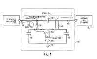
- FIG. 1is a schematic circuit diagram of a DC pass RF coaxial surge protector with a gas tube in accordance with various embodiments of the invention
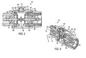
- FIG. 2is a cross-sectional view of a DC pass RF coaxial surge protector with a gas tube having the schematic circuit diagram shown in FIG. 1 in accordance with various embodiments of the invention
- FIG. 3is a perspective view of the DC pass RF coaxial surge protector of FIG. 2 partially showing the inside components in accordance with various embodiments of the invention
- FIG. 4is a cross-sectional view of the DC pass RF coaxial surge protector of FIG. 3 in accordance with various embodiments of the invention
- FIGS. 5A-5Eare various exterior views of the DC pass RF coaxial surge protector of FIG. 2 in accordance with various embodiments of the invention.
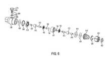
- FIG. 6is a disassembled perspective view of the DC pass RF coaxial surge protector of FIG. 4 in accordance with various embodiments of the invention.
- FIG. 7is a schematic circuit diagram of a DC pass RF coaxial surge protector with two gas tubes in accordance with various embodiments of the invention.
- FIG. 8is a cross-sectional view of a DC pass RF coaxial surge protector with two gas tubes having the schematic circuit diagram shown in FIG. 7 in accordance with various embodiments of the invention
- FIG. 9is a perspective view of the DC pass RF coaxial surge protector of FIG. 8 partially showing the inside components in accordance with various embodiments of the invention.
- FIG. 10is a cross-sectional view of the DC pass RF coaxial surge protector of FIG. 9 in accordance with various embodiments of the invention.
- FIGS. 11A-11Eare various exterior views of the DC pass RF coaxial surge protector of FIG. 8 in accordance with various embodiments of the invention.
- FIG. 12is a disassembled perspective view of the DC pass RF coaxial surge protector of FIG. 10 in accordance with various embodiments of the invention.
- FIG. 13is a schematic circuit diagram of a DC pass RF coaxial surge protector with three gas tubes in accordance with various embodiments of the invention.
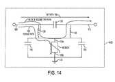
- FIG. 14is a schematic circuit diagram of a DC pass RF coaxial surge protector with a MOV in accordance with various embodiments of the invention.
- FIG. 16is a cross-sectional view of the DC pass RF coaxial surge protector of FIG. 15 in accordance with various embodiments of the invention.
- FIG. 17is a schematic circuit diagram of a DC short RF coaxial surge protector that does not pass DC but rather shorts the DC to ground in accordance with various embodiments of the invention.
- FIG. 18is a cross-sectional view of a DC short RF coaxial surge protector having the schematic circuit diagram shown in FIG. 17 in accordance with various embodiments of the invention.
- FIG. 19is a perspective view of the DC short RF coaxial surge protector of FIG. 18 partially showing the inside components in accordance with various embodiments of the invention.
- FIG. 20is a cross-sectional view of the DC short RF coaxial surge protector of FIG. 19 in accordance with various embodiments of the invention.
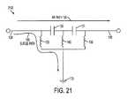
- FIG. 21is a schematic circuit diagram of a DC short RF coaxial surge protector that does not pass DC but rather shorts the DC to ground in accordance with various embodiments of the invention.
- the outer edges of the first, second and third spiral inductorsare connected to the ground (e.g., the housing);
- FIG. 22is a cross-sectional view of a DC short RF coaxial surge protector having the schematic circuit diagram shown in FIG. 21 in accordance with various embodiments of the invention.
- FIG. 23is a perspective view of the DC short RF coaxial surge protector of FIG. 22 partially showing the inside components in accordance with various embodiments of the invention.
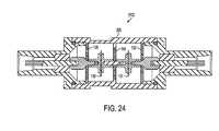
- FIG. 24is a cross-sectional view of the DC short RF coaxial surge protector of FIG. 22 in accordance with various embodiments of the invention.
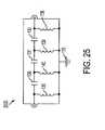
- FIG. 25is a schematic circuit diagram of a DC short RF coaxial surge protector that does not pass DC but rather shorts the DC to ground in accordance with various embodiments of the invention.
- FIG. 26is a cross-sectional view of a DC short RF coaxial surge protector having the schematic circuit diagram shown in FIG. 25 in accordance with various embodiments of the invention.
- FIG. 27is a perspective view of the DC short RF coaxial surge protector of FIG. 26 partially showing the inside components in accordance with various embodiments of the invention.
- FIG. 28is a cross-sectional view of the DC short RF coaxial surge protector of FIG. 26 in accordance with various embodiments of the invention.
- FIGS. 29 and 30are 3-dimensional views of the DC short RF coaxial surge protector of FIG. 26 in accordance with various embodiments of the invention.
- Surge protectorsprotect electronic equipment from being damaged by large variations in the current and voltage across power and transmission lines resulting from lightning strikes, switching surges, transients, noise, incorrect connections, and other abnormal conditions or malfunctions.
- Large variations in the power and transmission line currents and voltagescan change the operating frequency range of the electronic equipment and can severely damage and/or destroy the electronic equipment.
- a surge conditioncan arise in many different situations, however, typically arises when a lightning bolt strikes a component or transmission line which is coupled to the protected hardware and equipment.
- Lightning surgesgenerally include D.C. electrical energy and AC electrical energy up to approximately 1 MHz in frequency. Lightning is a complex electromagnetic energy source having potentials estimated at from 5 million to 20 million volts and currents reaching thousands of amperes that can severely damage and/or destroy the electronic equipment.
- FIG. 1is a schematic circuit diagram of a DC pass RF coaxial surge protector 100 (also can be referred to as a surge suppressor) with a non-linear protection device 105 in accordance with various embodiments of the invention.
- FIG. 2is a cross-sectional view of a DC pass RF coaxial surge protector 100 with a non-linear protection device 105 having the schematic circuit diagram shown in FIG. 1 in accordance with various embodiments of the invention.
- the surge protector 100protects hardware and equipment 125 from an electrical surge 120 that can damage or destroy the hardware and equipment 125 .
- the protected hardware and equipment 125can be any communications equipment, cell towers, base stations, PC computers, servers, network components or equipment, network connectors, or any other type of surge sensitive electronic equipment.
- the surge protector 100has various components each of which are structured to form the desired impedance, e.g., 50 ohms.
- the surge protector 100has a housing 205 that defines a cavity 210 .
- the cavity 210may be formed in the shape of a cylinder.
- the center conductors 109 and 110are positioned concentric with and located in the cavity 210 of the housing 205 .
- the surge protector 100includes a RF path 155 , a DC path 160 and a surge path 165 .
- the RF path 155includes an input center conductor 109 , a capacitor 130 and an output center conductor 110 .
- the frequency range of operation for the surge protector 100is between about 698 MHz and about 2.5 GHz. In one embodiment, the frequency range of operation is 1.5 GHz to 2.5 GHz, within which the insertion loss is specified less than 0.1 dB and the VSWR is specified less than 1.1:1. In another embodiment, the frequency range of operation is 2.0 GHz to 5.0 GHz, within which the insertion loss is specified less than 0.2 dB and the VSWR is specified less than 1.2:1.
- the values produced abovecan vary depending on the frequency range, degree of surge protection, and RF performance desired.
- RF signalstravel across the RF path 155 to the hardware and equipment 125 .
- the protected hardware and equipment 125receive and/or transmit RF signals along the RF path 155 .
- the surge protector 100can operate in a bidirectional manner.
- the capacitor 130is positioned in series with and positioned between the input and output center conductors 109 and 110 .
- the capacitor 130has a value of between about 3 picoFarads (pF) and about 15 pF, and preferably about 4.5 pF.
- the higher capacitance valuesallow for better lower frequency performance.
- the capacitor 130is a capacitive device realized in either lumped or distributed form. Alternatively, the capacitor 130 can be parallel rods, coupling devices, conductive plates, or any other device or combination of elements which produce a capacitive effect.
- the capacitance of the capacitor 130can vary depending on the frequency of operation desired by the user.
- the capacitor 130blocks the flow of direct current (DC) and permits the flow of alternating current (AC) depending on the capacitor's capacitance and the current frequency. At certain frequencies, the capacitor 130 might attenuate the AC signal. Typically, the capacitor 130 is placed in-line with the center conductors 109 and 110 to block the DC signal and undesirable surge transients.
- DCdirect current
- ACalternating current
- the DC power 115may be supplied through the surge protector 100 to the hardware and equipment 125 via a DC path 160 .
- the DC path 160includes the input center conductor 109 , a first spiral coil or inductor 135 , a second spiral coil or inductor 140 , and the outer center conductor 110 .
- the configuration of the DC path 160causes the DC current to be forced or directed outside the RF path 155 around the capacitor 130 .
- the DC currentis moved off the center conductors 109 and 110 and the capacitor 130 and directed or diverted through the inductors 135 and 140 toward the non-linear protection device 105 (e.g., a gas tube).
- the DC current and telemetry signalse.g., 10-20 MHz telemetry signals
- the surge 120travels across or along the surge path 165 (i.e., across the input center conductor 109 , the inductor 135 , and the gas tube 105 ).
- the surge 120travels across the gas tube 105 to a ground 170 (e.g., the housing).
- the gas tube 105is isolated from (i.e., is not directly connected to) the center conductors 109 and 110 by the first and second inductors 135 and 140 . That is, the first and second inductors 135 and 140 prevent the gas tube 105 from being directly connected to the RF path 155 .
- the gas tube 105contains hermetically sealed electrodes, which ionize gas during use. When the gas is ionized, the gas tube 105 becomes conductive and the breakdown voltage is lowered. The breakdown voltage varies and is dependent upon the rise time of the surge 120 . Therefore, depending on the surge 120 , several microseconds may elapse before the gas tube 105 becomes ionized, thus resulting in the leading portion of the surge 120 passing to the inductor 140 .
- the gas tube 105is coupled at a first end 105 a to the first inductor 135 and at a second end 105 b to ground 170 , thus diverting the surge current to ground 170 .
- the first end 105 a of the gas tube 105may also be connected to the second inductor 140 .
- the gas tube 105has a capacitance value of about 2 pF and a turn-on voltage of between about 90 volts and about 360 volts, and preferably about 180 volts to allow generous DC operating voltages.
- the first and second spiral inductors 135 and 140have small foot print designs and are formed as flat, planar designs.
- the first and second spiral inductors 135 and 140have values of between about 10 nano-Henry (nH) and about 25 nH, and preferably between about 17-20 nH.
- the chosen values for the first and second spiral inductors 135 and 140are important factors in determining the specific RF frequency ranges of operation for the surge protector 100 .
- the diameter, surface area, thickness, and shape of the first and second spiral inductors 135 and 140can be varied to adjust the operating frequencies and current handling capabilities of the surge protector 100 .
- an iterative processmay be used to determine the diameter, surface area, thickness, and shape of the first and second spiral inductors 135 and 140 to meet the user's particular application.
- the diameter of the first and second spiral inductors 135 and 140 of this package size and frequency rangeis typically 0.865 inches.
- the thickness of the first and second spiral inductors 135 and 140 of this package size and frequency rangeis typically 0.062 inches.
- the spiral inductors 130spiral in an outward direction.
- the material composition of the first and second spiral inductors 135 and 140is an important factor in determining the amount of charge that can be safely dissipated across the first and second spiral inductors 135 and 140 .
- a high tensile strength materialallows the first and second spiral inductors 135 and 140 to discharge or divert a greater amount of the current.
- the first and second spiral inductors 135 and 140are made of a 7075-T6 Aluminum material.
- any material having a good tensile strength and conductivitycan be used to manufacture the first and second spiral inductors 135 and 140 .
- Each of the components and the housingmay be plated with a silver material or a tri-metal flash plating to improve Passive InterModulation (PIM) performance. This reduces or eliminates the number of dissimilar or different types of metal connections or components in the RF path to improve PIM performance.
- PIMPassive InterModulation
- each spiral inductorhas an inner radius of approximately 62.5 mils and an outer radius of approximately 432.5 mils. An inner edge of each spiral inductor is coupled to the center conductor. An outer edge of each spiral inductor is coupled to the gas tube 105 .
- the spiral inductors 135 and 140may be of a particular known type such as the Archemedes, Logarithmic, or Hyperbolic spiral, or a combination of these spirals.
- the inner radius of the cavity 210is approximately 432.5 mils.
- the housing 205is coupled to a common ground connection to discharge the electrical energy.
- each spiral inductorspirals in an outward direction. In one embodiment, each spiral inductor has four spirals. The number of spirals and thickness of each spiral can be varied depending on the user's particular application.
- the electrical energy or surge currentfirst reaches the inner edge of the first spiral inductor 135 .
- the electrical energyis then dissipated through the spirals of the first spiral inductor 135 in an outward direction.
- the electrical energyis dissipated or diverted to ground 170 or to the housing 205 through the gas tube 105 .
- the housing 205may have an opening 220 that travels from a top surface 225 to the cavity 210 .
- the opening 220allows easy access into the cavity 210 of the housing 205 from outside the housing 205 .
- the surge protector 100also includes a removable cap 215 that is used to cover or seal the opening 220 in the housing 205 .
- the removable cap 215has threads that mate with grooves in the housing 205 to allow the removable cap 215 to be screwed into the housing 205 .
- the removable cap 215allows a technician to unscrew or remove the removable cap 215 to easily inspect and/or replace the non-linear protection device 105 .
- the non-linear protection device 105is partially positioned within the opening 220 and partially positioned within an interior open portion 216 of the removable cap 215 .
- the non-linear protection device 105is generally connected to the removable cap 215 .
- the non-linear protection device 105can be replaced with a short.
- the input center conductor 109 , the first inductor 135 , the capacitor 130 , the second inductor 140 , a first tuning capacitor 145 , a second tuning capacitor 150 , and the output center conductor 110are positioned within the cavity 210 of the housing 205 .
- the input and output center conductors 109 and 110are positioned along an axis 305 .
- the first inductor 135is positioned along a first plane 315 and the second inductor 140 is positioned along a second plane 310 .
- the first plane 315is positioned substantially parallel to the second plane 310 .
- the axis 305is positioned substantially perpendicular to the first plane 315 and the second plane 310 .
- the first tuning capacitor 145 and the second tuning capacitor 150are positioned and sized to allow the technician to use various capacitors to allow for the adjustment and fine tuning of the RF frequencies passing across or through the surge protector 100 .
- the first and second tuning capacitors 145 and 150can each have a capacitance value of between about 20 pF and about 200 pF, and preferably about 150 pF.
- the first and second tuning capacitors 145 and 150are formed using ring washers 608 of known insulating and dielectric properties.
- the ring washers 608may be Kapton insulating ring washers or dielectric ring washers.
- a first ring washer 608is positioned between the first capacitors 145 and the housing 205 and a second ring washer 608 is positioned between the second capacitor 150 and the housing 205 .
- the first and second capacitors 145 and 150serve as decoupling capacitors for tuning purposes while providing insulation for the DC circuit from the housing 205 .
- the insulating members 221 and 222electrically isolate the center conductors 109 and 110 from the housing 205 .
- the insulating members 221 and 222may be made of a dielectric material such Teflon which has a dielectric constant of approximately 2.3.
- the insulating members 221 and 222are typically cylindrically shaped with a center hole for allowing passage of the center conductors 109 and 110 .
- FIG. 4is a cross-sectional view of the DC pass RF coaxial surge protector of FIG. 3 in accordance with various embodiments of the invention.
- the electrical energy or surge currentcomes in on an outer shield of the center conductor 109 and is blocked by the capacitor 130 .
- the electrical energy or surge currentis then diverted through the spirals of the spiral inductor 135 and then to the non-linear protection device 105 .
- the non-linear protection device 105breaks down at a specified breakdown voltage, and then the electrical energy or surge current is diverted to the housing 205 or is grounded using the housing 205 or ground 170 .
- FIGS. 5A-5Eare various exterior views of the DC pass RF coaxial surge protector 100 of FIG. 2 in accordance with various embodiments of the invention.
- FIG. 5Ais a perspective view of the housing 205 showing the removable cap 215
- FIG. 5Bis a front view of the housing 205 showing a male DIN connector 501 on one side of the housing 205 and a female DIN connector 502 on the other side of the housing 205
- FIG. 5Cis a rear view of the housing 205
- FIG. 5Dis a left end view of the housing 205 showing the female DIN connector 502
- FIG. 5Eis a right end view of the housing 205 showing the male DIN connector 501 .
- FIG. 6is a disassembled perspective view of the DC pass RF coaxial surge protector of FIG. 4 in accordance with various embodiments of the invention.
- Several components or partsare identified herein as examples. All components or parts may not be necessary to make the DC pass RF coaxial surge protector but are provided to illustrate exemplary components or parts list.
- the surge protector 100may include the removable cap 215 , a first washer 603 , a first O-ring 604 , a gas tube 605 , a second O-ring 606 , the housing 205 , dielectric ring washers 608 (e.g., Kapton insulating ring washers), a third O-ring 609 , cap washers 610 , a DIN female contact 611 , Teflon inserts 612 , DIN extensions 613 , the first inductor 135 , the capacitor 130 , the second inductor 140 , a coil capture device 617 , a DIN male contact 618 , a DIN male end 619 , a DIN male snap ring 620 , a DIN male nut 621 , and a fourth O-ring 622 .
- dielectric ring washers 608e.g., Kapton insulating ring washers
- cap washers 610e.g., Kapton insulating ring washers
- FIG. 7is a schematic circuit diagram of a DC pass RF coaxial surge protector 700 with two non-linear protection devices 105 and 106 (e.g., gas tubes 105 and 106 ) in accordance with various embodiments of the invention.
- FIG. 8is a cross-sectional view of the DC pass RF coaxial surge protector 700 with two gas tubes 105 and 106 having the schematic circuit diagram shown in FIG. 7 in accordance with various embodiments of the invention.
- FIG. 9is a perspective view of the DC pass RF coaxial surge protector 700 of FIG. 8 partially showing the inside components in accordance with various embodiments of the invention.
- FIG. 10is a cross-sectional view of the DC pass RF coaxial surge protector of FIG. 9 in accordance with various embodiments of the invention.
- FIGS. 7-10are similar to FIGS. 1-4 with the addition of a second gas tube 106 . In one embodiment, the second gas tube 106 may be used for redundancy purposes.
- the surge path 165includes the first inductor 135 and the first gas tube 105 and/or the second gas tube 106 . If the first gas tube 105 is unable to divert all the surge energy, the second gas tube 106 is used to divert a portion of or all of the surge energy. Also, the second gas tube 106 can be used for redundancy purposes if the first gas tube 105 malfunctions or has already been discharged due to a prior surge. Once the gas tubes 105 and 106 discharge, the surge travels across the gas tubes 105 and 106 to a ground 170 (e.g., the housing 205 ).
- a ground 170e.g., the housing 205
- the gas tubes 105 and 106may have different turn-on voltages and therefore may discharge at different times.
- the first gas tube 105may have a turn-on voltage of about 120 volts while the second gas tube 106 may have a turn-on voltage of about 150 volts, and therefore the first gas tube 105 will breakdown at an earlier time than the second gas tube 106 .
- the gas tubes 105 and 106may have the same turn-on voltages.
- Each non-linear protection device 105 and 106can be a gas tube, a metal oxide varistor (MOV), a diode, and combinations thereof.
- MOVmetal oxide varistor
- the housing 205may have a second opening 223 that travels from a bottom surface 226 to the cavity 210 .
- the second opening 223allows easy access into the cavity 210 of the housing 205 .
- the surge protector 700also includes a second removable cap 217 that is used to cover or seal the second opening 223 in the housing 205 .
- the non-linear protection device 106e.g., the second gas tube 106
- the second removable cap 217has threads that mate with grooves in the housing 205 .
- the second removable cap 217allows a technician to unscrew or remove the second removable cap 217 to easily inspect and/or replace the non-linear protection device 106 .
- FIGS. 11A-11Eare various exterior views of the DC pass RF coaxial surge protector 700 of FIG. 8 in accordance with various embodiments of the invention.
- FIG. 5Ais a perspective view of the housing 205 showing the removable cap 215
- FIG. 5Bis a front view of the housing 205 showing a male DIN connector 501 on one side of the housing 205 and a female DIN connector 502 on the other side of the housing 205
- FIG. 5Cis a rear view of the housing 205
- FIG. 5Dis a left end view of the housing 205 showing the female DIN connector 502
- FIG. 5Eis a right end view of the housing 205 showing the male DIN connector 501 .
- FIG. 12is a disassembled perspective view of the DC pass RF coaxial surge protector 700 of FIG. 10 in accordance with various embodiments of the invention.
- Several components or partsare identified herein as examples. All components or parts may not be necessary to make the DC pass RF coaxial surge protector but are provided to illustrate exemplary components or parts list.
- the surge protector 100may include the removable cap 215 , a first washer 603 , a first O-ring 604 , a gas tube 605 , a second O-ring 606 , the housing 205 , ring washers 608 , a third O-ring 609 , cap washers 610 , a DIN female contact 611 , Teflon inserts 612 , DIN extensions 613 , the first inductor 135 , the capacitor 130 , the second inductor 140 , a coil capture device 617 , a DIN male contact 618 , a DIN male end 619 , a DIN male snap ring 620 , a DIN male nut 621 , and a fourth O-ring 622 .
- FIG. 13is a schematic circuit diagram of a DC pass RF coaxial surge protector 1300 with three gas tubes 105 , 106 and 107 in accordance with various embodiments of the invention.
- the surge path 165includes the first inductor 135 and the first gas tube 105 , the second gas tube 106 and/or the third gas tube 107 . If the first gas tube 105 is unable to divert all the surge energy, the second gas tube 106 and/or the third gas tube 107 may be used to divert a portion of or all of the surge energy.
- the second gas tube 106 and the third gas tube 107can be used for redundancy purposes if the first gas tube 105 malfunctions or has already been discharged due to a prior surge.
- the surgetravels across the gas tubes 105 , 106 and 107 to a ground 170 (e.g., the housing 205 ).
- the gas tubes 105 , 106 and 107may have different turn-on voltages and therefore may discharge at different times.
- the gas tubes 105 , 106 and 107may have the same turn-on voltages.
- Each non-linear protection device 105 , 106 and 107can be a gas tube, a metal oxide varistor (MOV), a diode, and combinations thereof.
- MOVmetal oxide varistor
- FIG. 14is a schematic circuit diagram of a DC pass RF coaxial surge protector 1400 with a MOV 108 in accordance with various embodiments of the invention.
- MOVsare typically utilized as voltage limiting elements. If the voltage at the MOV 108 is below its clamping or switching voltage, the MOV 108 exhibits a high resistance. If the voltage at the MOV 108 is above its clamping or switching voltage, the MOV 108 exhibits a low resistance. Hence, MOVs are sometimes referred to as non-linear resistors because of their nonlinear current-voltage relationship.
- the MOV 108is attached at one end 108 a to the first inductor 135 and at another end 108 b to the ground 170 .
- FIG. 15is a schematic circuit diagram of a DC pass RF coaxial surge protector 1500 with a gas tube 105 and a diode 111 in accordance with various embodiments of the invention.
- a primary surge path 165includes the gas tube 105 and a fine surge path 175 includes the diode 111 .
- the main part of the surgeis passed across the gas tube 105 and any portion of the surge that is not diverted by the gas tube 105 is diverted to ground 170 by the diode 111 .
- FIG. 16is a cross-sectional view of the DC pass RF coaxial surge protector 1500 of FIG. 15 in accordance with various embodiments of the invention.
- the gas tube 105is positioned above the first inductor 135 along a first plane 181 and the diode 111 is positioned below the second inductor 140 along a second plane 182 .
- the location of the gas tube 105is offset or staggered from the location of the diode 111 such that these two devices do not lie along the same vertical plane.
- the first plane 181 and the second plane 182are substantially parallel to one another but are not concentric to one another.
- a portion 138 of the cavity 210produces inductance.
- FIG. 17is a schematic circuit diagram of a DC short RF coaxial surge protector 1700 that does not pass DC but rather shorts the DC to ground 170 in accordance with various embodiments of the invention. Hence, the outer edges of both the first and second spiral inductors 135 and 140 are connected to the ground 170 (e.g., the housing 205 ).
- FIG. 18is a cross-sectional view of a DC short RF coaxial surge protector 1700 having the schematic circuit diagram shown in FIG. 17 in accordance with various embodiments of the invention.
- FIG. 19is a perspective view of the DC short RF coaxial surge protector 1700 of FIG. 18 partially showing the inside components in accordance with various embodiments of the invention.
- FIG. 20is a cross-sectional view of the DC short RF coaxial surge protector 1700 of FIG. 19 in accordance with various embodiments of the invention. As shown, the outer edges of both the first and second spiral inductors 135 and 140 are connected to the housing 205 .
- FIG. 21is a schematic circuit diagram of a DC short RF coaxial surge protector 2100 that does not pass DC but rather shorts the DC to ground 170 in accordance with various embodiments of the invention.
- the outer edges of the first, second and third spiral inductors 135 , 140 and 139are connected to the ground 170 (e.g., the housing 205 ).
- the DC short RF coaxial surge protector 2300is a 5-pole design. Providing the additional poles allows for better attenuation or filtering of low frequency signals without adversely affecting the RF performance.
- the 5-pole designFIG. 21
- the 3-pole designFIG. 17
- the 7-pole designFIG.
- the 7-pole designhas a ⁇ 80 dB attenuation at approximately 100 MHz
- the 5-pole designhas ⁇ 80 dB attenuation at approximately 55 MHz
- the 3-pole designhas a ⁇ 80 dB attenuation at approximately 30 MHz.
- FIG. 22is a cross-sectional view of a DC short RF coaxial surge protector 2100 having the schematic circuit diagram shown in FIG. 21 in accordance with various embodiments of the invention.
- FIG. 23is a perspective view of the DC short RF coaxial surge protector 2100 of FIG. 22 partially showing the inside components in accordance with various embodiments of the invention.
- FIG. 24is a cross-sectional view of the DC short RF coaxial surge protector 2100 of FIG. 22 in accordance with various embodiments of the invention. As shown, the outer edges of the first, second and third spiral inductors 135 , 140 and 139 are directly connected to the housing 205 .
- FIG. 25is a schematic circuit diagram of a DC short RF coaxial surge protector 2500 that does not pass DC but rather shorts the DC to ground 170 in accordance with various embodiments of the invention.
- FIG. 26is a cross-sectional view of a DC short RF coaxial surge protector 2500 having the schematic circuit diagram shown in FIG. 25 in accordance with various embodiments of the invention.
- FIG. 27is a perspective view of the DC short RF coaxial surge protector 2500 of FIG. 26 partially showing the inside components in accordance with various embodiments of the invention.
- FIG. 28is a cross-sectional view of the DC short RF coaxial surge protector 2500 of FIG. 26 in accordance with various embodiments of the invention.
- 29 and 30are 3-dimensional views of the DC short RF coaxial surge protector 2500 of FIG. 26 in accordance with various embodiments of the invention. As shown, the outer edges of the first, second, third and fourth spiral inductors 135 , 140 , 139 and 138 are directly connected to the housing 205 .
Landscapes
- Emergency Protection Circuit Devices (AREA)
Abstract
Description
Claims (18)
Priority Applications (1)
| Application Number | Priority Date | Filing Date | Title |
|---|---|---|---|
| US12/897,658US8456791B2 (en) | 2009-10-02 | 2010-10-04 | RF coaxial surge protectors with non-linear protection devices |
Applications Claiming Priority (2)
| Application Number | Priority Date | Filing Date | Title |
|---|---|---|---|
| US24833409P | 2009-10-02 | 2009-10-02 | |
| US12/897,658US8456791B2 (en) | 2009-10-02 | 2010-10-04 | RF coaxial surge protectors with non-linear protection devices |
Publications (2)
| Publication Number | Publication Date |
|---|---|
| US20110080683A1 US20110080683A1 (en) | 2011-04-07 |
| US8456791B2true US8456791B2 (en) | 2013-06-04 |
Family
ID=43823012
Family Applications (1)
| Application Number | Title | Priority Date | Filing Date |
|---|---|---|---|
| US12/897,658Active2032-01-28US8456791B2 (en) | 2009-10-02 | 2010-10-04 | RF coaxial surge protectors with non-linear protection devices |
Country Status (3)
| Country | Link |
|---|---|
| US (1) | US8456791B2 (en) |
| CN (1) | CN102742101A (en) |
| WO (1) | WO2011041801A2 (en) |
Cited By (3)
| Publication number | Priority date | Publication date | Assignee | Title |
|---|---|---|---|---|
| US20110279943A1 (en)* | 2010-05-11 | 2011-11-17 | Transtector Systems, Inc. | Dc pass rf protector having a surge suppression module |
| US20120212306A1 (en)* | 2011-02-21 | 2012-08-23 | Zih Corp. | Isolation devices that pass coupler output signals |
| US10193335B2 (en)* | 2015-10-27 | 2019-01-29 | Transtector Systems, Inc. | Radio frequency surge protector with matched piston-cylinder cavity shape |
Families Citing this family (32)
| Publication number | Priority date | Publication date | Assignee | Title |
|---|---|---|---|---|
| WO2009052517A2 (en) | 2007-10-18 | 2009-04-23 | Polyphaser Corporation | Surge suppression device having one or more rings |
| WO2009059044A2 (en)* | 2007-10-30 | 2009-05-07 | Polyphaser Corporation | Surge protection circuit for passing dc and rf signals |
| CN102027651B (en)* | 2008-05-19 | 2014-06-04 | 特兰斯泰克塔系统公司 | DC and RF pass broadband surge suppressor |
| US8456791B2 (en) | 2009-10-02 | 2013-06-04 | Transtector Systems, Inc. | RF coaxial surge protectors with non-linear protection devices |
| US8400760B2 (en)* | 2009-12-28 | 2013-03-19 | Transtector Systems, Inc. | Power distribution device |
| WO2012145029A2 (en) | 2011-04-19 | 2012-10-26 | Exxonmobil Chemical Patents Inc. | Process for producing phenol |
| US20110271802A1 (en) | 2010-05-04 | 2011-11-10 | Edward Honig | Double handle tool |
| US8441795B2 (en) | 2010-05-04 | 2013-05-14 | Transtector Systems, Inc. | High power band pass RF filter having a gas tube for surge suppression |
| US8611062B2 (en) | 2010-05-13 | 2013-12-17 | Transtector Systems, Inc. | Surge current sensor and surge protection system including the same |
| WO2011150087A2 (en) | 2010-05-26 | 2011-12-01 | Transtector Systems, Inc. | Dc block rf coaxial devices |
| US8730637B2 (en) | 2010-12-17 | 2014-05-20 | Transtector Systems, Inc. | Surge protection devices that fail as an open circuit |
| US8810989B2 (en)* | 2011-04-18 | 2014-08-19 | Alcatel Lucent | DC pass filter using flat inductor in cavity |
| US9054514B2 (en) | 2012-02-10 | 2015-06-09 | Transtector Systems, Inc. | Reduced let through voltage transient protection or suppression circuit |
| US9048662B2 (en) | 2012-03-19 | 2015-06-02 | Transtector Systems, Inc. | DC power surge protector |
| US9190837B2 (en) | 2012-05-03 | 2015-11-17 | Transtector Systems, Inc. | Rigid flex electromagnetic pulse protection device |
| US9124093B2 (en) | 2012-09-21 | 2015-09-01 | Transtector Systems, Inc. | Rail surge voltage protector with fail disconnect |
| US8858262B2 (en)* | 2012-12-04 | 2014-10-14 | Genesis Technology Usa, Inc. | F-connector with integrated surge protection |
| US9124091B2 (en) | 2013-11-26 | 2015-09-01 | Thomson Licensing | Surge protector for a transmission line connector |
| WO2016200700A1 (en) | 2015-06-09 | 2016-12-15 | Transtector Systems, Inc. | Sealed enclosure for protecting electronics |
| US10588236B2 (en) | 2015-07-24 | 2020-03-10 | Transtector Systems, Inc. | Modular protection cabinet with flexible backplane |
| US10356928B2 (en) | 2015-07-24 | 2019-07-16 | Transtector Systems, Inc. | Modular protection cabinet with flexible backplane |
| US9924609B2 (en) | 2015-07-24 | 2018-03-20 | Transtector Systems, Inc. | Modular protection cabinet with flexible backplane |
| US20180048145A1 (en)* | 2016-08-12 | 2018-02-15 | Hamilton Sundstrand Corporation | Transient voltage protection circuits |
| US9991697B1 (en) | 2016-12-06 | 2018-06-05 | Transtector Systems, Inc. | Fail open or fail short surge protector |
| US20180330880A1 (en) | 2017-05-15 | 2018-11-15 | Avx Corporation | Multilayer capacitor and circuit board containing the same |
| IL271711B2 (en)* | 2017-06-29 | 2024-11-01 | Kyocera Avx Components Corp | A surface mount multilayer coupling capacitor and an electrical circuit board containing it |
| IT201800021403A1 (en)* | 2018-12-28 | 2020-06-28 | Solexy S R L | EXPLOSION PROOF CONNECTION FOR ANTENNA, WITH IMPROVED PROTECTION |
| CN113424280B (en) | 2019-02-13 | 2023-01-03 | 京瓷Avx元器件公司 | Multilayer ceramic capacitor including conductive path |
| CN110556804B (en)* | 2019-09-26 | 2024-06-07 | 深圳市速联技术有限公司 | Comprehensive protective device for radio frequency coaxial strong transient electromagnetic pulse |
| CN110556805A (en)* | 2019-09-26 | 2019-12-10 | 深圳市速联技术有限公司 | Ultra-wideband radio frequency coaxial lightning electromagnetic pulse protection method and device |
| US12185516B1 (en)* | 2020-09-03 | 2024-12-31 | Jacob C. Weber | Apparatuses, systems, and methods for protection against the effects of an electromagnetic pulse |
| CN117981022A (en) | 2021-07-08 | 2024-05-03 | 京瓷Avx元器件公司 | Multilayer Ceramic Capacitors |
Citations (108)
| Publication number | Priority date | Publication date | Assignee | Title |
|---|---|---|---|---|
| US2030179A (en) | 1933-01-19 | 1936-02-11 | American Telephone & Telegraph | Electrical circuit arrangement |
| US3167729A (en) | 1962-10-29 | 1965-01-26 | Sylvania Electric Prod | Microwave filter insertable within outer wall of coaxial line |
| US3323083A (en) | 1965-03-17 | 1967-05-30 | Amp Inc | Means and method for transmission line compensation |
| US3619721A (en) | 1970-06-01 | 1971-11-09 | Gen Electric | Triggered vacuum gap keep-alive circuit |
| US3663901A (en) | 1970-02-27 | 1972-05-16 | Amp Inc | Tuned coaxial device |
| US3731234A (en) | 1971-12-27 | 1973-05-01 | Bell Telephone Labor Inc | Combined voice frequency transmission and dc signaling circuit |
| US3750053A (en) | 1972-04-24 | 1973-07-31 | Plessey Inc | Coaxial transmission line rf switch |
| US3783178A (en) | 1972-08-03 | 1974-01-01 | Gen Signal Corp | Expansion joint for connecting rigid conduit with grounding continuity |
| US3831110A (en) | 1972-05-01 | 1974-08-20 | Cornell Res Foundation Inc | Multi-axis cavities for microwave semiconductors |
| US3845358A (en) | 1973-06-29 | 1974-10-29 | Gen Electric | Integrated polycrystalline varistor surge protective device for high frequency applications |
| US3944937A (en) | 1973-12-06 | 1976-03-16 | Matsushita Electric Industrial Co., Ltd. | Broad-band signal transmitting device using transformer |
| US3980976A (en) | 1974-03-28 | 1976-09-14 | Sony Corporation | Coaxial connector |
| US4047120A (en) | 1976-07-15 | 1977-09-06 | The United States Of America As Represented By The Secretary Of The Navy | Transient suppression circuit for push-pull switching amplifiers |
| US4046451A (en) | 1976-07-08 | 1977-09-06 | Andrew Corporation | Connector for coaxial cable with annularly corrugated outer conductor |
| US4112395A (en) | 1977-06-10 | 1978-09-05 | Cincinnati Electronics Corp. | Method of and apparatus for matching a load circuit to a drive circuit |
| US4262317A (en) | 1979-03-22 | 1981-04-14 | Reliable Electric Company | Line protector for a communications circuit |
| US4359764A (en) | 1980-04-08 | 1982-11-16 | Block Roger R | Connector for electromagnetic impulse suppression |
| US4384331A (en) | 1979-04-23 | 1983-05-17 | Nissan Motor Company, Limited | Noise suppressor for vehicle digital system |
| US4409637A (en) | 1980-04-08 | 1983-10-11 | Block Roger R | Connector for electromagnetic impulse suppression |
| US4481641A (en) | 1982-09-30 | 1984-11-06 | Ford Motor Company | Coaxial cable tap coupler for a data transceiver |
| US4554608A (en) | 1982-11-15 | 1985-11-19 | Block Roger R | Connector for electromagnetic impulse suppression |
| US4563720A (en) | 1984-04-17 | 1986-01-07 | General Semiconductor Industries, Inc. | Hybrid AC line transient suppressor |
| US4586104A (en) | 1983-12-12 | 1986-04-29 | Rit Research Corp. | Passive overvoltage protection devices, especially for protection of computer equipment connected to data lines |
| US4689713A (en) | 1985-06-12 | 1987-08-25 | Les Cables De Lyon | High voltage surge protection for electrical power line |
| US4698721A (en) | 1983-11-07 | 1987-10-06 | Puroflow Corp. | Power line filter for transient and continuous noise suppression |
| US4727350A (en) | 1986-04-28 | 1988-02-23 | Hitoshi Ohkubo | Surge absorber |
| US4841253A (en)* | 1987-04-15 | 1989-06-20 | Harris Corporation | Multiple spiral inductors for DC biasing of an amplifier |
| US4864250A (en)* | 1987-01-29 | 1989-09-05 | Harris Corporation | Distributed amplifier having improved D.C. biasing and voltage standing wave ratio performance |
| US4952173A (en) | 1986-09-05 | 1990-08-28 | Raychem Pontoise | Circuit protection device |
| CH675933A5 (en) | 1989-07-27 | 1990-11-15 | Huber+Suhner Ag | Triaxial electromagnetic pulse conductor - has inner conductor and two screening conductors with unit to maintain contact with overload conductor |
| US4984146A (en) | 1990-03-27 | 1991-01-08 | International Business Machines Corporation | Suppression of radiated EMI for power supplies |
| US4985800A (en) | 1989-10-30 | 1991-01-15 | Feldman Nathan W | Lighting protection apparatus for RF equipment and the like |
| US5053910A (en) | 1989-10-16 | 1991-10-01 | Perma Power Electronics, Inc. | Surge suppressor for coaxial transmission line |
| US5057964A (en) | 1986-12-17 | 1991-10-15 | Northern Telecom Limited | Surge protector for telecommunications terminals |
| US5102818A (en) | 1989-09-21 | 1992-04-07 | Deutsche Itt Industries Gmbh | Method for the smooth fine classification of varactor diodes |
| US5122921A (en) | 1990-04-26 | 1992-06-16 | Industrial Communication Engineers, Ltd. | Device for electromagnetic static and voltage suppression |
| US5124873A (en) | 1989-10-30 | 1992-06-23 | Efi Corporation | Surge suppression circuit for high frequency communication networks |
| US5142429A (en) | 1990-05-07 | 1992-08-25 | Telefonaktiebolaget L M Ericsson | Overvoltage and overcurrent protective circuit with high earth balance |
| US5166855A (en) | 1991-02-27 | 1992-11-24 | Semitron Industries Ltd. | Surge protector with thermal failsafe |
| US5278720A (en) | 1991-09-20 | 1994-01-11 | Atlantic Scientific Corp. | Printed circuit-mounted surge suppressor matched to characteristic impedance of high frequency transmission line |
| US5321573A (en) | 1992-07-16 | 1994-06-14 | Dale Electronics, Inc. | Monolythic surge suppressor |
| US5353189A (en) | 1992-11-02 | 1994-10-04 | Tomlinson John C | Surge protector for vehicular traffic monitoring equipment |
| US5442330A (en) | 1993-12-27 | 1995-08-15 | Motorola, Inc. | Coupled line filter with improved out-of-band rejection |
| US5537044A (en) | 1994-09-30 | 1996-07-16 | The United States Of America As Represented By The Secretary Of The Navy | Surge voltage generator for pulsing grounded and ungrounded electrical equipment |
| US5617284A (en) | 1994-08-05 | 1997-04-01 | Paradise; Rick | Power surge protection apparatus and method |
| US5625521A (en) | 1994-07-22 | 1997-04-29 | Pacusma Co.,Ltd. | Surge protection circuitry |
| US5667298A (en) | 1996-01-16 | 1997-09-16 | Cedarapids, Inc. | Portable concrete mixer with weigh/surge systems |
| US5721662A (en) | 1992-07-29 | 1998-02-24 | Act Communications, Inc. | Floating ground isolator for a communications cable locating system |
| US5781844A (en) | 1995-03-22 | 1998-07-14 | Scientific-Atlanta, Inc. | Method and apparatus for distributing a power signal and an RF signal |
| US5790361A (en) | 1997-03-31 | 1998-08-04 | The Whitaker Corporation | Coaxial surge protector with impedance matching |
| US5844766A (en) | 1997-09-09 | 1998-12-01 | Forem S.R.L. | Lightning supression system for tower mounted antenna systems |
| US5854730A (en) | 1997-09-15 | 1998-12-29 | Mitchell; Dennis | Transient and voltage surge protection system and method for preventing damage to electrical equipment |
| US5953195A (en) | 1997-02-26 | 1999-09-14 | Reltec Corporation | Coaxial protector |
| US5966283A (en) | 1995-08-18 | 1999-10-12 | Act Communications, Inc. | Surge suppression for radio frequency transmission lines |
| US5982602A (en) | 1993-10-07 | 1999-11-09 | Andrew Corporation | Surge protector connector |
| US5986869A (en) | 1998-02-05 | 1999-11-16 | Polyphaser Corporation | Grounding panel |
| US6054905A (en) | 1998-01-21 | 2000-04-25 | General Instrument Coporation | User configurable CATV power inserter |
| US6060182A (en) | 1997-06-09 | 2000-05-09 | Teikoku Piston Ring Co., Ltd. | Hard coating material, sliding member covered with hard coating material and manufacturing method thereof |
| US6061223A (en) | 1997-10-14 | 2000-05-09 | Polyphaser Corporation | Surge suppressor device |
| US6086544A (en) | 1999-03-31 | 2000-07-11 | Ethicon Endo-Surgery, Inc. | Control apparatus for an automated surgical biopsy device |
| US6137352A (en) | 1997-01-27 | 2000-10-24 | Huber And Suhner Ag | Circuit arrangement for protection of HF-input-circuit on telecommunications devices |
| US6141194A (en) | 1998-09-22 | 2000-10-31 | Simmonds Precision Products, Inc. | Aircraft fuel tank protective barrier and method |
| US6177849B1 (en) | 1998-11-18 | 2001-01-23 | Oneline Ag | Non-saturating, flux cancelling diplex filter for power line communications |
| US6243247B1 (en) | 1998-09-22 | 2001-06-05 | Polyphaser Corporation | Stripline transient protection device |
| US6252755B1 (en) | 1999-08-11 | 2001-06-26 | Advanced Micro Devices, Inc. | Apparatus and method for implementing a home network using customer-premises power lines |
| US6281690B1 (en) | 1996-07-19 | 2001-08-28 | Lockheed Martin Corporation | Coaxial radio frequency test probe |
| US6342998B1 (en) | 1998-11-13 | 2002-01-29 | Leviton Manufacturing Co., Inc. | Data surge protection module |
| US6381283B1 (en) | 1998-10-07 | 2002-04-30 | Controlnet, Inc. | Integrated socket with chip carrier |
| US6385030B1 (en) | 1999-09-02 | 2002-05-07 | Marconi Communications, Inc. | Reduced signal loss surge protection circuit |
| US6394122B1 (en) | 2000-09-21 | 2002-05-28 | Pacific Seismic Products, Inc. | Shock actuated sensor for fluid valve |
| US6421220B2 (en) | 1998-05-29 | 2002-07-16 | Porta Systems Corporation | Low capacitance surge protector for high speed data transmission |
| US20020167302A1 (en) | 2001-05-09 | 2002-11-14 | Gallavan Michael F. | Surge current measurement |
| US20020191360A1 (en) | 2001-05-22 | 2002-12-19 | Enrico Colombo | Current detector for surge arrester diagnostic and overvoltage assessment in high voltage substations |
| US6502599B1 (en) | 2000-09-21 | 2003-01-07 | Pacific Seismic Products, Inc. | Shock actuated responsive mechanism for vertical fluid valve assemblies |
| US6527004B1 (en) | 2000-09-21 | 2003-03-04 | Pacific Seismic Products, Inc. | Shock actuated responsive mechanism for vertical fluid valve assemblies |
| US20030072121A1 (en) | 2001-10-12 | 2003-04-17 | Polyphaser Corporation | Rf surge protection device |
| US20030211782A1 (en) | 2002-05-07 | 2003-11-13 | Mr. Joseph Lorenzo De Guzman | Filtered RJ11 connector module with LED indicators and method of manufacturing |
| US6721155B2 (en) | 2001-08-23 | 2004-04-13 | Andrew Corp. | Broadband surge protector with stub DC injection |
| US6754060B2 (en) | 2000-07-06 | 2004-06-22 | George M. Kauffman | Protective device |
| US20040121648A1 (en) | 2002-07-26 | 2004-06-24 | V-Squared Networks | Network device for communicating information |
| US6757152B2 (en) | 2001-09-05 | 2004-06-29 | Avx Corporation | Cascade capacitor |
| US20040145849A1 (en) | 2002-11-15 | 2004-07-29 | Chang Byung-Ho | Surge protection device and method |
| US6789560B1 (en) | 2000-09-21 | 2004-09-14 | Pacific Seismic Products, Inc. | Shock actuated responsive mechanism with improved safety means to prevent over-rotation of the valve reset mechanism |
| US6814100B1 (en) | 2000-09-21 | 2004-11-09 | Pacific Seismic Products, Inc. | Shock actuated responsive mechanism with means to enable a remote detecting means to determine that the valve assembly has been closed |
| US20040264087A1 (en) | 2003-06-30 | 2004-12-30 | Bishop Roger S | Transient protector for wireless communications equipment |
| US20050036262A1 (en) | 2003-07-09 | 2005-02-17 | Siebenthall Fred Mac | DC Voltage surge suppressor with distributed capacitance EMI filtering and impedance matching |
| US20050044858A1 (en) | 2003-08-26 | 2005-03-03 | Kenneth Hooker | Two stage solenoid control valve |
| US20050176275A1 (en) | 2004-02-05 | 2005-08-11 | Panamax | Modular signal and power connection device |
| US20050185354A1 (en) | 2004-02-25 | 2005-08-25 | Hoopes Gerald B. | Protection of A/V components |
| US6968852B1 (en) | 2000-09-21 | 2005-11-29 | Pacific Seismic Products, Inc. | Shock actuated responsive mechanism with improved dual safety means to prevent over-rotation of the valve reset mechanism and to provide easy access to the reset knob |
| US6975496B2 (en) | 2002-03-21 | 2005-12-13 | Polyphaser Corporation | Isolated shield coaxial surge suppressor |
| US20060146458A1 (en) | 2005-01-03 | 2006-07-06 | Huberag | Surge suppressor with increased surge current capability |
| US7082022B2 (en) | 2002-05-31 | 2006-07-25 | Polyphaser Corporation | Circuit for diverting surges and transient impulses |
| US7106572B1 (en) | 1999-09-17 | 2006-09-12 | Adee Electronic (Societe A Responsabilite Limitee) | Device for protecting against voltage surges |
| US7130103B2 (en) | 2004-03-08 | 2006-10-31 | Seiko Epson Corporation | Optical modulator and manufacturing method of optical modulator |
| US7159236B2 (en) | 2000-06-30 | 2007-01-02 | Kabushiki Kaisha Toshiba | Transmission/reception integrated radio-frequency apparatus |
| US20070053130A1 (en) | 2005-09-01 | 2007-03-08 | Andrew Corporation | Offset Planar Coil Coaxial Surge Suppressor |
| US7215221B1 (en)* | 2004-08-30 | 2007-05-08 | Hrl Laboratories, Llc | Harmonic termination circuit for medium bandwidth microwave power amplifiers |
| US20070139850A1 (en) | 2005-12-15 | 2007-06-21 | Raycap Corporation | Overvoltage protection devices including wafer of varistor material |
| US7250829B2 (en) | 2001-09-14 | 2007-07-31 | Matsushita Electric Industrial Co., Ltd. | High frequency switch |
| US7430103B2 (en) | 2003-09-19 | 2008-09-30 | Sharp Kabushiki Kaisha | Static electricity protective circuit and high-frequency circuit apparatus incorporating the same |
| US20090103226A1 (en) | 2007-10-18 | 2009-04-23 | Polyphaser Corporation | Surge suppression device having one or more rings |
| US20090109584A1 (en) | 2007-10-30 | 2009-04-30 | Polyphaser Corporation | Surge protection circuit for passing dc and rf signals |
| US20090284888A1 (en) | 2008-05-19 | 2009-11-19 | Polyphaser Corporation | Dc and rf pass broadband surge suppressor |
| US7623332B2 (en) | 2008-01-31 | 2009-11-24 | Commscope, Inc. Of North Carolina | Low bypass fine arrestor |
| US7808752B2 (en) | 2004-08-17 | 2010-10-05 | Semiconductor Components Industries, Llc | Integrated passive filter incorporating inductors and ESD protectors |
| US20110080683A1 (en) | 2009-10-02 | 2011-04-07 | Jones Jonathan L | Rf coaxial surge protectors with non-linear protection devices |
| US20110159727A1 (en) | 2009-12-28 | 2011-06-30 | Matt Howard | Power distribution device |
Family Cites Families (2)
| Publication number | Priority date | Publication date | Assignee | Title |
|---|---|---|---|---|
| JPS58225586A (en)* | 1982-06-23 | 1983-12-27 | ヒロセ電機株式会社 | Coaxial arrester structure |
| CN100377447C (en)* | 2005-03-14 | 2008-03-26 | 四川康姆逊电磁防护有限责任公司 | Lightning protection coaxial connector |
- 2010
- 2010-10-04USUS12/897,658patent/US8456791B2/enactiveActive
- 2010-10-04CNCN2010800032515Apatent/CN102742101A/enactivePending
- 2010-10-04WOPCT/US2010/051374patent/WO2011041801A2/enactiveApplication Filing
Patent Citations (116)
| Publication number | Priority date | Publication date | Assignee | Title |
|---|---|---|---|---|
| US2030179A (en) | 1933-01-19 | 1936-02-11 | American Telephone & Telegraph | Electrical circuit arrangement |
| US3167729A (en) | 1962-10-29 | 1965-01-26 | Sylvania Electric Prod | Microwave filter insertable within outer wall of coaxial line |
| US3323083A (en) | 1965-03-17 | 1967-05-30 | Amp Inc | Means and method for transmission line compensation |
| US3663901A (en) | 1970-02-27 | 1972-05-16 | Amp Inc | Tuned coaxial device |
| US3619721A (en) | 1970-06-01 | 1971-11-09 | Gen Electric | Triggered vacuum gap keep-alive circuit |
| US3731234A (en) | 1971-12-27 | 1973-05-01 | Bell Telephone Labor Inc | Combined voice frequency transmission and dc signaling circuit |
| US3750053A (en) | 1972-04-24 | 1973-07-31 | Plessey Inc | Coaxial transmission line rf switch |
| US3831110A (en) | 1972-05-01 | 1974-08-20 | Cornell Res Foundation Inc | Multi-axis cavities for microwave semiconductors |
| US3783178A (en) | 1972-08-03 | 1974-01-01 | Gen Signal Corp | Expansion joint for connecting rigid conduit with grounding continuity |
| US3845358A (en) | 1973-06-29 | 1974-10-29 | Gen Electric | Integrated polycrystalline varistor surge protective device for high frequency applications |
| US3944937A (en) | 1973-12-06 | 1976-03-16 | Matsushita Electric Industrial Co., Ltd. | Broad-band signal transmitting device using transformer |
| US3980976A (en) | 1974-03-28 | 1976-09-14 | Sony Corporation | Coaxial connector |
| US4046451A (en) | 1976-07-08 | 1977-09-06 | Andrew Corporation | Connector for coaxial cable with annularly corrugated outer conductor |
| US4047120A (en) | 1976-07-15 | 1977-09-06 | The United States Of America As Represented By The Secretary Of The Navy | Transient suppression circuit for push-pull switching amplifiers |
| US4112395A (en) | 1977-06-10 | 1978-09-05 | Cincinnati Electronics Corp. | Method of and apparatus for matching a load circuit to a drive circuit |
| US4262317A (en) | 1979-03-22 | 1981-04-14 | Reliable Electric Company | Line protector for a communications circuit |
| US4384331A (en) | 1979-04-23 | 1983-05-17 | Nissan Motor Company, Limited | Noise suppressor for vehicle digital system |
| US4359764A (en) | 1980-04-08 | 1982-11-16 | Block Roger R | Connector for electromagnetic impulse suppression |
| US4409637A (en) | 1980-04-08 | 1983-10-11 | Block Roger R | Connector for electromagnetic impulse suppression |
| US4481641A (en) | 1982-09-30 | 1984-11-06 | Ford Motor Company | Coaxial cable tap coupler for a data transceiver |
| US4554608A (en) | 1982-11-15 | 1985-11-19 | Block Roger R | Connector for electromagnetic impulse suppression |
| US4698721A (en) | 1983-11-07 | 1987-10-06 | Puroflow Corp. | Power line filter for transient and continuous noise suppression |
| US4586104A (en) | 1983-12-12 | 1986-04-29 | Rit Research Corp. | Passive overvoltage protection devices, especially for protection of computer equipment connected to data lines |
| US4563720A (en) | 1984-04-17 | 1986-01-07 | General Semiconductor Industries, Inc. | Hybrid AC line transient suppressor |
| US4689713A (en) | 1985-06-12 | 1987-08-25 | Les Cables De Lyon | High voltage surge protection for electrical power line |
| US4727350B1 (en) | 1986-04-28 | 1994-02-01 | Ohkubo Hitoshi | Surge absorber |
| US4727350A (en) | 1986-04-28 | 1988-02-23 | Hitoshi Ohkubo | Surge absorber |
| US4952173A (en) | 1986-09-05 | 1990-08-28 | Raychem Pontoise | Circuit protection device |
| US5057964A (en) | 1986-12-17 | 1991-10-15 | Northern Telecom Limited | Surge protector for telecommunications terminals |
| US4864250A (en)* | 1987-01-29 | 1989-09-05 | Harris Corporation | Distributed amplifier having improved D.C. biasing and voltage standing wave ratio performance |
| US4841253A (en)* | 1987-04-15 | 1989-06-20 | Harris Corporation | Multiple spiral inductors for DC biasing of an amplifier |
| CH675933A5 (en) | 1989-07-27 | 1990-11-15 | Huber+Suhner Ag | Triaxial electromagnetic pulse conductor - has inner conductor and two screening conductors with unit to maintain contact with overload conductor |
| US5102818A (en) | 1989-09-21 | 1992-04-07 | Deutsche Itt Industries Gmbh | Method for the smooth fine classification of varactor diodes |
| US5053910A (en) | 1989-10-16 | 1991-10-01 | Perma Power Electronics, Inc. | Surge suppressor for coaxial transmission line |
| US4985800A (en) | 1989-10-30 | 1991-01-15 | Feldman Nathan W | Lighting protection apparatus for RF equipment and the like |
| US5124873A (en) | 1989-10-30 | 1992-06-23 | Efi Corporation | Surge suppression circuit for high frequency communication networks |
| US4984146A (en) | 1990-03-27 | 1991-01-08 | International Business Machines Corporation | Suppression of radiated EMI for power supplies |
| US5122921A (en) | 1990-04-26 | 1992-06-16 | Industrial Communication Engineers, Ltd. | Device for electromagnetic static and voltage suppression |
| US5142429A (en) | 1990-05-07 | 1992-08-25 | Telefonaktiebolaget L M Ericsson | Overvoltage and overcurrent protective circuit with high earth balance |
| US5166855A (en) | 1991-02-27 | 1992-11-24 | Semitron Industries Ltd. | Surge protector with thermal failsafe |
| US5278720A (en) | 1991-09-20 | 1994-01-11 | Atlantic Scientific Corp. | Printed circuit-mounted surge suppressor matched to characteristic impedance of high frequency transmission line |
| US5321573A (en) | 1992-07-16 | 1994-06-14 | Dale Electronics, Inc. | Monolythic surge suppressor |
| US5721662A (en) | 1992-07-29 | 1998-02-24 | Act Communications, Inc. | Floating ground isolator for a communications cable locating system |
| US6292344B1 (en) | 1992-07-29 | 2001-09-18 | Act Communications, Inc. | Floating ground isolator for a communications cable locating system |
| US5353189A (en) | 1992-11-02 | 1994-10-04 | Tomlinson John C | Surge protector for vehicular traffic monitoring equipment |
| US5982602A (en) | 1993-10-07 | 1999-11-09 | Andrew Corporation | Surge protector connector |
| US5442330A (en) | 1993-12-27 | 1995-08-15 | Motorola, Inc. | Coupled line filter with improved out-of-band rejection |
| US5625521A (en) | 1994-07-22 | 1997-04-29 | Pacusma Co.,Ltd. | Surge protection circuitry |
| US5617284A (en) | 1994-08-05 | 1997-04-01 | Paradise; Rick | Power surge protection apparatus and method |
| US5537044A (en) | 1994-09-30 | 1996-07-16 | The United States Of America As Represented By The Secretary Of The Navy | Surge voltage generator for pulsing grounded and ungrounded electrical equipment |
| US5781844A (en) | 1995-03-22 | 1998-07-14 | Scientific-Atlanta, Inc. | Method and apparatus for distributing a power signal and an RF signal |
| US5966283A (en) | 1995-08-18 | 1999-10-12 | Act Communications, Inc. | Surge suppression for radio frequency transmission lines |
| US5667298A (en) | 1996-01-16 | 1997-09-16 | Cedarapids, Inc. | Portable concrete mixer with weigh/surge systems |
| US6281690B1 (en) | 1996-07-19 | 2001-08-28 | Lockheed Martin Corporation | Coaxial radio frequency test probe |
| US6137352A (en) | 1997-01-27 | 2000-10-24 | Huber And Suhner Ag | Circuit arrangement for protection of HF-input-circuit on telecommunications devices |
| US5953195A (en) | 1997-02-26 | 1999-09-14 | Reltec Corporation | Coaxial protector |
| US5790361A (en) | 1997-03-31 | 1998-08-04 | The Whitaker Corporation | Coaxial surge protector with impedance matching |
| US6060182A (en) | 1997-06-09 | 2000-05-09 | Teikoku Piston Ring Co., Ltd. | Hard coating material, sliding member covered with hard coating material and manufacturing method thereof |
| US5844766A (en) | 1997-09-09 | 1998-12-01 | Forem S.R.L. | Lightning supression system for tower mounted antenna systems |
| US5854730A (en) | 1997-09-15 | 1998-12-29 | Mitchell; Dennis | Transient and voltage surge protection system and method for preventing damage to electrical equipment |
| US6061223A (en) | 1997-10-14 | 2000-05-09 | Polyphaser Corporation | Surge suppressor device |
| US6115227A (en) | 1997-10-14 | 2000-09-05 | Polyphaser Corporation | Surge suppressor device |
| US6236551B1 (en) | 1997-10-14 | 2001-05-22 | Polyphaser Corporation | Surge suppressor device |
| US6054905A (en) | 1998-01-21 | 2000-04-25 | General Instrument Coporation | User configurable CATV power inserter |
| US5986869A (en) | 1998-02-05 | 1999-11-16 | Polyphaser Corporation | Grounding panel |
| US6421220B2 (en) | 1998-05-29 | 2002-07-16 | Porta Systems Corporation | Low capacitance surge protector for high speed data transmission |
| US6243247B1 (en) | 1998-09-22 | 2001-06-05 | Polyphaser Corporation | Stripline transient protection device |
| US6141194A (en) | 1998-09-22 | 2000-10-31 | Simmonds Precision Products, Inc. | Aircraft fuel tank protective barrier and method |
| US6381283B1 (en) | 1998-10-07 | 2002-04-30 | Controlnet, Inc. | Integrated socket with chip carrier |
| US6342998B1 (en) | 1998-11-13 | 2002-01-29 | Leviton Manufacturing Co., Inc. | Data surge protection module |
| US6177849B1 (en) | 1998-11-18 | 2001-01-23 | Oneline Ag | Non-saturating, flux cancelling diplex filter for power line communications |
| US6086544A (en) | 1999-03-31 | 2000-07-11 | Ethicon Endo-Surgery, Inc. | Control apparatus for an automated surgical biopsy device |
| US6252755B1 (en) | 1999-08-11 | 2001-06-26 | Advanced Micro Devices, Inc. | Apparatus and method for implementing a home network using customer-premises power lines |
| US6385030B1 (en) | 1999-09-02 | 2002-05-07 | Marconi Communications, Inc. | Reduced signal loss surge protection circuit |
| US7106572B1 (en) | 1999-09-17 | 2006-09-12 | Adee Electronic (Societe A Responsabilite Limitee) | Device for protecting against voltage surges |
| US7159236B2 (en) | 2000-06-30 | 2007-01-02 | Kabushiki Kaisha Toshiba | Transmission/reception integrated radio-frequency apparatus |
| US6754060B2 (en) | 2000-07-06 | 2004-06-22 | George M. Kauffman | Protective device |
| US6394122B1 (en) | 2000-09-21 | 2002-05-28 | Pacific Seismic Products, Inc. | Shock actuated sensor for fluid valve |
| US6789560B1 (en) | 2000-09-21 | 2004-09-14 | Pacific Seismic Products, Inc. | Shock actuated responsive mechanism with improved safety means to prevent over-rotation of the valve reset mechanism |
| US6527004B1 (en) | 2000-09-21 | 2003-03-04 | Pacific Seismic Products, Inc. | Shock actuated responsive mechanism for vertical fluid valve assemblies |
| US6968852B1 (en) | 2000-09-21 | 2005-11-29 | Pacific Seismic Products, Inc. | Shock actuated responsive mechanism with improved dual safety means to prevent over-rotation of the valve reset mechanism and to provide easy access to the reset knob |
| US6502599B1 (en) | 2000-09-21 | 2003-01-07 | Pacific Seismic Products, Inc. | Shock actuated responsive mechanism for vertical fluid valve assemblies |
| US6814100B1 (en) | 2000-09-21 | 2004-11-09 | Pacific Seismic Products, Inc. | Shock actuated responsive mechanism with means to enable a remote detecting means to determine that the valve assembly has been closed |
| US20020167302A1 (en) | 2001-05-09 | 2002-11-14 | Gallavan Michael F. | Surge current measurement |
| US20020191360A1 (en) | 2001-05-22 | 2002-12-19 | Enrico Colombo | Current detector for surge arrester diagnostic and overvoltage assessment in high voltage substations |
| US6721155B2 (en) | 2001-08-23 | 2004-04-13 | Andrew Corp. | Broadband surge protector with stub DC injection |
| US6757152B2 (en) | 2001-09-05 | 2004-06-29 | Avx Corporation | Cascade capacitor |
| US7250829B2 (en) | 2001-09-14 | 2007-07-31 | Matsushita Electric Industrial Co., Ltd. | High frequency switch |
| US6785110B2 (en) | 2001-10-12 | 2004-08-31 | Polyphaser Corporation | Rf surge protection device |
| US20030072121A1 (en) | 2001-10-12 | 2003-04-17 | Polyphaser Corporation | Rf surge protection device |
| US6975496B2 (en) | 2002-03-21 | 2005-12-13 | Polyphaser Corporation | Isolated shield coaxial surge suppressor |
| US20030211782A1 (en) | 2002-05-07 | 2003-11-13 | Mr. Joseph Lorenzo De Guzman | Filtered RJ11 connector module with LED indicators and method of manufacturing |
| US7082022B2 (en) | 2002-05-31 | 2006-07-25 | Polyphaser Corporation | Circuit for diverting surges and transient impulses |
| US20040121648A1 (en) | 2002-07-26 | 2004-06-24 | V-Squared Networks | Network device for communicating information |
| US20040145849A1 (en) | 2002-11-15 | 2004-07-29 | Chang Byung-Ho | Surge protection device and method |
| US7221550B2 (en) | 2002-11-15 | 2007-05-22 | Samsung Electronics Co., Ltd. | Surge protection device and method |
| US20040264087A1 (en) | 2003-06-30 | 2004-12-30 | Bishop Roger S | Transient protector for wireless communications equipment |
| US20050036262A1 (en) | 2003-07-09 | 2005-02-17 | Siebenthall Fred Mac | DC Voltage surge suppressor with distributed capacitance EMI filtering and impedance matching |
| US20050044858A1 (en) | 2003-08-26 | 2005-03-03 | Kenneth Hooker | Two stage solenoid control valve |
| US7104282B2 (en) | 2003-08-26 | 2006-09-12 | Honeywell International, Inc. | Two stage solenoid control valve |
| US7430103B2 (en) | 2003-09-19 | 2008-09-30 | Sharp Kabushiki Kaisha | Static electricity protective circuit and high-frequency circuit apparatus incorporating the same |
| US20050176275A1 (en) | 2004-02-05 | 2005-08-11 | Panamax | Modular signal and power connection device |
| US20050185354A1 (en) | 2004-02-25 | 2005-08-25 | Hoopes Gerald B. | Protection of A/V components |
| US7130103B2 (en) | 2004-03-08 | 2006-10-31 | Seiko Epson Corporation | Optical modulator and manufacturing method of optical modulator |
| US7808752B2 (en) | 2004-08-17 | 2010-10-05 | Semiconductor Components Industries, Llc | Integrated passive filter incorporating inductors and ESD protectors |
| US7215221B1 (en)* | 2004-08-30 | 2007-05-08 | Hrl Laboratories, Llc | Harmonic termination circuit for medium bandwidth microwave power amplifiers |
| US20060146458A1 (en) | 2005-01-03 | 2006-07-06 | Huberag | Surge suppressor with increased surge current capability |
| US20070053130A1 (en) | 2005-09-01 | 2007-03-08 | Andrew Corporation | Offset Planar Coil Coaxial Surge Suppressor |
| US20070139850A1 (en) | 2005-12-15 | 2007-06-21 | Raycap Corporation | Overvoltage protection devices including wafer of varistor material |
| US20090103226A1 (en) | 2007-10-18 | 2009-04-23 | Polyphaser Corporation | Surge suppression device having one or more rings |
| US20090109584A1 (en) | 2007-10-30 | 2009-04-30 | Polyphaser Corporation | Surge protection circuit for passing dc and rf signals |
| US20110141646A1 (en) | 2007-10-30 | 2011-06-16 | Jones Jonathan L | Surge protection circuit for passing dc and rf signals |
| US7623332B2 (en) | 2008-01-31 | 2009-11-24 | Commscope, Inc. Of North Carolina | Low bypass fine arrestor |
| US20090284888A1 (en) | 2008-05-19 | 2009-11-19 | Polyphaser Corporation | Dc and rf pass broadband surge suppressor |
| US20110080683A1 (en) | 2009-10-02 | 2011-04-07 | Jones Jonathan L | Rf coaxial surge protectors with non-linear protection devices |
| US20110159727A1 (en) | 2009-12-28 | 2011-06-30 | Matt Howard | Power distribution device |
Cited By (6)
| Publication number | Priority date | Publication date | Assignee | Title |
|---|---|---|---|---|
| US20110279943A1 (en)* | 2010-05-11 | 2011-11-17 | Transtector Systems, Inc. | Dc pass rf protector having a surge suppression module |
| US8730640B2 (en)* | 2010-05-11 | 2014-05-20 | Transtector Systems, Inc. | DC pass RF protector having a surge suppression module |
| US20120212306A1 (en)* | 2011-02-21 | 2012-08-23 | Zih Corp. | Isolation devices that pass coupler output signals |
| US9000862B2 (en)* | 2011-02-21 | 2015-04-07 | Zih Corp. | Isolation devices that pass coupler output signals |
| US9520630B2 (en) | 2011-02-21 | 2016-12-13 | Zih Corp. | Isolation devices that pass coupler output signals |
| US10193335B2 (en)* | 2015-10-27 | 2019-01-29 | Transtector Systems, Inc. | Radio frequency surge protector with matched piston-cylinder cavity shape |
Also Published As
| Publication number | Publication date |
|---|---|
| WO2011041801A3 (en) | 2011-09-29 |
| CN102742101A (en) | 2012-10-17 |
| US20110080683A1 (en) | 2011-04-07 |
| WO2011041801A2 (en) | 2011-04-07 |
Similar Documents
| Publication | Publication Date | Title |
|---|---|---|
| US8456791B2 (en) | RF coaxial surge protectors with non-linear protection devices | |
| CA2798891C (en) | Dc pass rf protector having a surge suppression module | |
| US6751081B1 (en) | Surge protected coaxial termination | |
| US6785110B2 (en) | Rf surge protection device | |
| US8553386B2 (en) | Surge suppression device having one or more rings | |
| US7944670B2 (en) | Surge protection circuit for passing DC and RF signals | |
| US8976500B2 (en) | DC block RF coaxial devices | |
| US8599528B2 (en) | DC and RF pass broadband surge suppressor | |
| US9590287B2 (en) | Surge protected coaxial termination | |
| US8228656B2 (en) | Protective device for a radio frequency transmission line | |
| KR101410765B1 (en) | Stacking diode limiter | |
| US6950294B2 (en) | Surge protection filter and lightning conductor system | |
| US6791813B2 (en) | Communication line surge protecting system | |
| US9136701B2 (en) | High voltage discharge protection device and radio frequency transmission apparatus using the same | |
| KR200276121Y1 (en) | A lightning arrester |
Legal Events
| Date | Code | Title | Description |
|---|---|---|---|
| AS | Assignment | Owner name:TRANSTECTOR SYSTEMS, INC., IDAHO Free format text:ASSIGNMENT OF ASSIGNORS INTEREST;ASSIGNORS:JONES, JONATHAN L.;PENWELL, CHRIS;REEL/FRAME:025089/0150 Effective date:20101004 | |
| STCF | Information on status: patent grant | Free format text:PATENTED CASE | |
| FPAY | Fee payment | Year of fee payment:4 | |
| AS | Assignment | Owner name:ANTARES CAPITAL LP, AS ADMINISTRATIVE AGENT, ILLIN Free format text:SECURITY INTEREST;ASSIGNOR:TRANSTECTOR SYSTEMS, INC.;REEL/FRAME:042191/0680 Effective date:20170501 Owner name:ANTARES CAPITAL LP, AS ADMINISTRATIVE AGENT, ILLIN Free format text:SECURITY INTEREST;ASSIGNOR:TRANSTECTOR SYSTEMS, INC.;REEL/FRAME:042192/0095 Effective date:20170501 | |
| MAFP | Maintenance fee payment | Free format text:PAYMENT OF MAINTENANCE FEE, 8TH YEAR, LARGE ENTITY (ORIGINAL EVENT CODE: M1552); ENTITY STATUS OF PATENT OWNER: LARGE ENTITY Year of fee payment:8 | |
| AS | Assignment | Owner name:PASTERNACK ENTERPRISES, INC., CALIFORNIA Free format text:MERGER;ASSIGNOR:TRANSTECTOR SYSTEMS, INC.;REEL/FRAME:055432/0880 Effective date:20180319 Owner name:INFINITE ELECTRONICS INTERNATIONAL, INC., CALIFORNIA Free format text:CHANGE OF NAME;ASSIGNOR:PASTERNACK ENTERPRISES, INC.;REEL/FRAME:055437/0581 Effective date:20180319 | |
| AS | Assignment | Owner name:INFINITE ELECTRONICS INTERNATIONAL, INC., CALIFORNIA Free format text:PATENT RELEASE;ASSIGNOR:ANTARES CAPITAL LP, AS ADMINISTRATIVE AGENT;REEL/FRAME:055488/0714 Effective date:20210302 Owner name:INFINITE ELECTRONICS INTERNATIONAL, INC., CALIFORNIA Free format text:PATENT RELEASE 2L;ASSIGNOR:ANTARES CAPITAL LP, AS ADMINISTRATIVE AGENT;REEL/FRAME:055489/0142 Effective date:20210302 Owner name:JEFFERIES FINANCE LLC, NEW YORK Free format text:SECOND LIEN PATENT SECURITY AGREEMENT;ASSIGNOR:INFINITE ELECTRONICS INTERNATIONAL, INC.;REEL/FRAME:055526/0931 Effective date:20210302 Owner name:JEFFERIES FINANCE LLC, NEW YORK Free format text:FIRST LIEN PATENT SECURITY AGREEMENT;ASSIGNOR:INFINITE ELECTRONICS INTERNATIONAL, INC.;REEL/FRAME:055526/0898 Effective date:20210302 | |
| MAFP | Maintenance fee payment | Free format text:PAYMENT OF MAINTENANCE FEE, 12TH YEAR, LARGE ENTITY (ORIGINAL EVENT CODE: M1553); ENTITY STATUS OF PATENT OWNER: LARGE ENTITY Year of fee payment:12 |