US8455379B2 - Ceramic article - Google Patents
Ceramic articleDownload PDFInfo
- Publication number
- US8455379B2 US8455379B2US13/443,292US201213443292AUS8455379B2US 8455379 B2US8455379 B2US 8455379B2US 201213443292 AUS201213443292 AUS 201213443292AUS 8455379 B2US8455379 B2US 8455379B2
- Authority
- US
- United States
- Prior art keywords
- ceramic
- ceramic article
- fibers
- article
- typically
- Prior art date
- Legal status (The legal status is an assumption and is not a legal conclusion. Google has not performed a legal analysis and makes no representation as to the accuracy of the status listed.)
- Active
Links
Images


Classifications
- B—PERFORMING OPERATIONS; TRANSPORTING
- B28—WORKING CEMENT, CLAY, OR STONE
- B28B—SHAPING CLAY OR OTHER CERAMIC COMPOSITIONS; SHAPING SLAG; SHAPING MIXTURES CONTAINING CEMENTITIOUS MATERIAL, e.g. PLASTER
- B28B11/00—Apparatus or processes for treating or working the shaped or preshaped articles
- B28B11/24—Apparatus or processes for treating or working the shaped or preshaped articles for curing, setting or hardening
- B28B11/245—Curing concrete articles
- B—PERFORMING OPERATIONS; TRANSPORTING
- B28—WORKING CEMENT, CLAY, OR STONE
- B28B—SHAPING CLAY OR OTHER CERAMIC COMPOSITIONS; SHAPING SLAG; SHAPING MIXTURES CONTAINING CEMENTITIOUS MATERIAL, e.g. PLASTER
- B28B21/00—Methods or machines specially adapted for the production of tubular articles
- B28B21/42—Methods or machines specially adapted for the production of tubular articles by shaping on or against mandrels or like moulding surfaces
- B28B21/48—Methods or machines specially adapted for the production of tubular articles by shaping on or against mandrels or like moulding surfaces by wrapping, e.g. winding
- B—PERFORMING OPERATIONS; TRANSPORTING
- B29—WORKING OF PLASTICS; WORKING OF SUBSTANCES IN A PLASTIC STATE IN GENERAL
- B29B—PREPARATION OR PRETREATMENT OF THE MATERIAL TO BE SHAPED; MAKING GRANULES OR PREFORMS; RECOVERY OF PLASTICS OR OTHER CONSTITUENTS OF WASTE MATERIAL CONTAINING PLASTICS
- B29B7/00—Mixing; Kneading
- B29B7/30—Mixing; Kneading continuous, with mechanical mixing or kneading devices
- B29B7/34—Mixing; Kneading continuous, with mechanical mixing or kneading devices with movable mixing or kneading devices
- B29B7/38—Mixing; Kneading continuous, with mechanical mixing or kneading devices with movable mixing or kneading devices rotary
- B29B7/46—Mixing; Kneading continuous, with mechanical mixing or kneading devices with movable mixing or kneading devices rotary with more than one shaft
- B29B7/48—Mixing; Kneading continuous, with mechanical mixing or kneading devices with movable mixing or kneading devices rotary with more than one shaft with intermeshing devices, e.g. screws
- B29B7/485—Mixing; Kneading continuous, with mechanical mixing or kneading devices with movable mixing or kneading devices rotary with more than one shaft with intermeshing devices, e.g. screws with three or more shafts provided with screws
- B—PERFORMING OPERATIONS; TRANSPORTING
- B29—WORKING OF PLASTICS; WORKING OF SUBSTANCES IN A PLASTIC STATE IN GENERAL
- B29C—SHAPING OR JOINING OF PLASTICS; SHAPING OF MATERIAL IN A PLASTIC STATE, NOT OTHERWISE PROVIDED FOR; AFTER-TREATMENT OF THE SHAPED PRODUCTS, e.g. REPAIRING
- B29C48/00—Extrusion moulding, i.e. expressing the moulding material through a die or nozzle which imparts the desired form; Apparatus therefor
- B29C48/022—Extrusion moulding, i.e. expressing the moulding material through a die or nozzle which imparts the desired form; Apparatus therefor characterised by the choice of material
- B—PERFORMING OPERATIONS; TRANSPORTING
- B29—WORKING OF PLASTICS; WORKING OF SUBSTANCES IN A PLASTIC STATE IN GENERAL
- B29C—SHAPING OR JOINING OF PLASTICS; SHAPING OF MATERIAL IN A PLASTIC STATE, NOT OTHERWISE PROVIDED FOR; AFTER-TREATMENT OF THE SHAPED PRODUCTS, e.g. REPAIRING
- B29C48/00—Extrusion moulding, i.e. expressing the moulding material through a die or nozzle which imparts the desired form; Apparatus therefor
- B29C48/03—Extrusion moulding, i.e. expressing the moulding material through a die or nozzle which imparts the desired form; Apparatus therefor characterised by the shape of the extruded material at extrusion
- B29C48/07—Flat, e.g. panels
- B29C48/08—Flat, e.g. panels flexible, e.g. films
- B—PERFORMING OPERATIONS; TRANSPORTING
- B29—WORKING OF PLASTICS; WORKING OF SUBSTANCES IN A PLASTIC STATE IN GENERAL
- B29C—SHAPING OR JOINING OF PLASTICS; SHAPING OF MATERIAL IN A PLASTIC STATE, NOT OTHERWISE PROVIDED FOR; AFTER-TREATMENT OF THE SHAPED PRODUCTS, e.g. REPAIRING
- B29C48/00—Extrusion moulding, i.e. expressing the moulding material through a die or nozzle which imparts the desired form; Apparatus therefor
- B29C48/03—Extrusion moulding, i.e. expressing the moulding material through a die or nozzle which imparts the desired form; Apparatus therefor characterised by the shape of the extruded material at extrusion
- B29C48/12—Articles with an irregular circumference when viewed in cross-section, e.g. window profiles
- B—PERFORMING OPERATIONS; TRANSPORTING
- B29—WORKING OF PLASTICS; WORKING OF SUBSTANCES IN A PLASTIC STATE IN GENERAL
- B29C—SHAPING OR JOINING OF PLASTICS; SHAPING OF MATERIAL IN A PLASTIC STATE, NOT OTHERWISE PROVIDED FOR; AFTER-TREATMENT OF THE SHAPED PRODUCTS, e.g. REPAIRING
- B29C48/00—Extrusion moulding, i.e. expressing the moulding material through a die or nozzle which imparts the desired form; Apparatus therefor
- B29C48/03—Extrusion moulding, i.e. expressing the moulding material through a die or nozzle which imparts the desired form; Apparatus therefor characterised by the shape of the extruded material at extrusion
- B29C48/13—Articles with a cross-section varying in the longitudinal direction, e.g. corrugated pipes
- B—PERFORMING OPERATIONS; TRANSPORTING
- B29—WORKING OF PLASTICS; WORKING OF SUBSTANCES IN A PLASTIC STATE IN GENERAL
- B29C—SHAPING OR JOINING OF PLASTICS; SHAPING OF MATERIAL IN A PLASTIC STATE, NOT OTHERWISE PROVIDED FOR; AFTER-TREATMENT OF THE SHAPED PRODUCTS, e.g. REPAIRING
- B29C48/00—Extrusion moulding, i.e. expressing the moulding material through a die or nozzle which imparts the desired form; Apparatus therefor
- B29C48/25—Component parts, details or accessories; Auxiliary operations
- B29C48/88—Thermal treatment of the stream of extruded material, e.g. cooling
- B29C48/91—Heating, e.g. for cross linking
- B29C48/9105—Heating, e.g. for cross linking of hollow articles
- C—CHEMISTRY; METALLURGY
- C04—CEMENTS; CONCRETE; ARTIFICIAL STONE; CERAMICS; REFRACTORIES
- C04B—LIME, MAGNESIA; SLAG; CEMENTS; COMPOSITIONS THEREOF, e.g. MORTARS, CONCRETE OR LIKE BUILDING MATERIALS; ARTIFICIAL STONE; CERAMICS; REFRACTORIES; TREATMENT OF NATURAL STONE
- C04B35/00—Shaped ceramic products characterised by their composition; Ceramics compositions; Processing powders of inorganic compounds preparatory to the manufacturing of ceramic products
- C04B35/515—Shaped ceramic products characterised by their composition; Ceramics compositions; Processing powders of inorganic compounds preparatory to the manufacturing of ceramic products based on non-oxide ceramics
- C04B35/56—Shaped ceramic products characterised by their composition; Ceramics compositions; Processing powders of inorganic compounds preparatory to the manufacturing of ceramic products based on non-oxide ceramics based on carbides or oxycarbides
- C04B35/565—Shaped ceramic products characterised by their composition; Ceramics compositions; Processing powders of inorganic compounds preparatory to the manufacturing of ceramic products based on non-oxide ceramics based on carbides or oxycarbides based on silicon carbide
- C—CHEMISTRY; METALLURGY
- C04—CEMENTS; CONCRETE; ARTIFICIAL STONE; CERAMICS; REFRACTORIES
- C04B—LIME, MAGNESIA; SLAG; CEMENTS; COMPOSITIONS THEREOF, e.g. MORTARS, CONCRETE OR LIKE BUILDING MATERIALS; ARTIFICIAL STONE; CERAMICS; REFRACTORIES; TREATMENT OF NATURAL STONE
- C04B35/00—Shaped ceramic products characterised by their composition; Ceramics compositions; Processing powders of inorganic compounds preparatory to the manufacturing of ceramic products
- C04B35/622—Forming processes; Processing powders of inorganic compounds preparatory to the manufacturing of ceramic products
- C04B35/62204—Forming processes; Processing powders of inorganic compounds preparatory to the manufacturing of ceramic products using waste materials or refuse
- C—CHEMISTRY; METALLURGY
- C04—CEMENTS; CONCRETE; ARTIFICIAL STONE; CERAMICS; REFRACTORIES
- C04B—LIME, MAGNESIA; SLAG; CEMENTS; COMPOSITIONS THEREOF, e.g. MORTARS, CONCRETE OR LIKE BUILDING MATERIALS; ARTIFICIAL STONE; CERAMICS; REFRACTORIES; TREATMENT OF NATURAL STONE
- C04B35/00—Shaped ceramic products characterised by their composition; Ceramics compositions; Processing powders of inorganic compounds preparatory to the manufacturing of ceramic products
- C04B35/622—Forming processes; Processing powders of inorganic compounds preparatory to the manufacturing of ceramic products
- C04B35/626—Preparing or treating the powders individually or as batches ; preparing or treating macroscopic reinforcing agents for ceramic products, e.g. fibres; mechanical aspects section B
- C04B35/62605—Treating the starting powders individually or as mixtures
- C04B35/62625—Wet mixtures
- C04B35/6263—Wet mixtures characterised by their solids loadings, i.e. the percentage of solids
- C—CHEMISTRY; METALLURGY
- C04—CEMENTS; CONCRETE; ARTIFICIAL STONE; CERAMICS; REFRACTORIES
- C04B—LIME, MAGNESIA; SLAG; CEMENTS; COMPOSITIONS THEREOF, e.g. MORTARS, CONCRETE OR LIKE BUILDING MATERIALS; ARTIFICIAL STONE; CERAMICS; REFRACTORIES; TREATMENT OF NATURAL STONE
- C04B35/00—Shaped ceramic products characterised by their composition; Ceramics compositions; Processing powders of inorganic compounds preparatory to the manufacturing of ceramic products
- C04B35/622—Forming processes; Processing powders of inorganic compounds preparatory to the manufacturing of ceramic products
- C04B35/626—Preparing or treating the powders individually or as batches ; preparing or treating macroscopic reinforcing agents for ceramic products, e.g. fibres; mechanical aspects section B
- C04B35/62605—Treating the starting powders individually or as mixtures
- C04B35/62625—Wet mixtures
- C04B35/62635—Mixing details
- C—CHEMISTRY; METALLURGY
- C04—CEMENTS; CONCRETE; ARTIFICIAL STONE; CERAMICS; REFRACTORIES
- C04B—LIME, MAGNESIA; SLAG; CEMENTS; COMPOSITIONS THEREOF, e.g. MORTARS, CONCRETE OR LIKE BUILDING MATERIALS; ARTIFICIAL STONE; CERAMICS; REFRACTORIES; TREATMENT OF NATURAL STONE
- C04B35/00—Shaped ceramic products characterised by their composition; Ceramics compositions; Processing powders of inorganic compounds preparatory to the manufacturing of ceramic products
- C04B35/622—Forming processes; Processing powders of inorganic compounds preparatory to the manufacturing of ceramic products
- C04B35/626—Preparing or treating the powders individually or as batches ; preparing or treating macroscopic reinforcing agents for ceramic products, e.g. fibres; mechanical aspects section B
- C04B35/62605—Treating the starting powders individually or as mixtures
- C04B35/62645—Thermal treatment of powders or mixtures thereof other than sintering
- C04B35/62655—Drying, e.g. freeze-drying, spray-drying, microwave or supercritical drying
- C—CHEMISTRY; METALLURGY
- C04—CEMENTS; CONCRETE; ARTIFICIAL STONE; CERAMICS; REFRACTORIES
- C04B—LIME, MAGNESIA; SLAG; CEMENTS; COMPOSITIONS THEREOF, e.g. MORTARS, CONCRETE OR LIKE BUILDING MATERIALS; ARTIFICIAL STONE; CERAMICS; REFRACTORIES; TREATMENT OF NATURAL STONE
- C04B35/00—Shaped ceramic products characterised by their composition; Ceramics compositions; Processing powders of inorganic compounds preparatory to the manufacturing of ceramic products
- C04B35/622—Forming processes; Processing powders of inorganic compounds preparatory to the manufacturing of ceramic products
- C04B35/626—Preparing or treating the powders individually or as batches ; preparing or treating macroscopic reinforcing agents for ceramic products, e.g. fibres; mechanical aspects section B
- C04B35/62605—Treating the starting powders individually or as mixtures
- C04B35/6269—Curing of mixtures
- C—CHEMISTRY; METALLURGY
- C04—CEMENTS; CONCRETE; ARTIFICIAL STONE; CERAMICS; REFRACTORIES
- C04B—LIME, MAGNESIA; SLAG; CEMENTS; COMPOSITIONS THEREOF, e.g. MORTARS, CONCRETE OR LIKE BUILDING MATERIALS; ARTIFICIAL STONE; CERAMICS; REFRACTORIES; TREATMENT OF NATURAL STONE
- C04B35/00—Shaped ceramic products characterised by their composition; Ceramics compositions; Processing powders of inorganic compounds preparatory to the manufacturing of ceramic products
- C04B35/622—Forming processes; Processing powders of inorganic compounds preparatory to the manufacturing of ceramic products
- C04B35/626—Preparing or treating the powders individually or as batches ; preparing or treating macroscopic reinforcing agents for ceramic products, e.g. fibres; mechanical aspects section B
- C04B35/63—Preparing or treating the powders individually or as batches ; preparing or treating macroscopic reinforcing agents for ceramic products, e.g. fibres; mechanical aspects section B using additives specially adapted for forming the products, e.g.. binder binders
- C04B35/6303—Inorganic additives
- C04B35/6316—Binders based on silicon compounds
- C—CHEMISTRY; METALLURGY
- C04—CEMENTS; CONCRETE; ARTIFICIAL STONE; CERAMICS; REFRACTORIES
- C04B—LIME, MAGNESIA; SLAG; CEMENTS; COMPOSITIONS THEREOF, e.g. MORTARS, CONCRETE OR LIKE BUILDING MATERIALS; ARTIFICIAL STONE; CERAMICS; REFRACTORIES; TREATMENT OF NATURAL STONE
- C04B35/00—Shaped ceramic products characterised by their composition; Ceramics compositions; Processing powders of inorganic compounds preparatory to the manufacturing of ceramic products
- C04B35/622—Forming processes; Processing powders of inorganic compounds preparatory to the manufacturing of ceramic products
- C04B35/626—Preparing or treating the powders individually or as batches ; preparing or treating macroscopic reinforcing agents for ceramic products, e.g. fibres; mechanical aspects section B
- C04B35/63—Preparing or treating the powders individually or as batches ; preparing or treating macroscopic reinforcing agents for ceramic products, e.g. fibres; mechanical aspects section B using additives specially adapted for forming the products, e.g.. binder binders
- C04B35/632—Organic additives
- C04B35/636—Polysaccharides or derivatives thereof
- C04B35/6365—Cellulose or derivatives thereof
- C—CHEMISTRY; METALLURGY
- C04—CEMENTS; CONCRETE; ARTIFICIAL STONE; CERAMICS; REFRACTORIES
- C04B—LIME, MAGNESIA; SLAG; CEMENTS; COMPOSITIONS THEREOF, e.g. MORTARS, CONCRETE OR LIKE BUILDING MATERIALS; ARTIFICIAL STONE; CERAMICS; REFRACTORIES; TREATMENT OF NATURAL STONE
- C04B35/00—Shaped ceramic products characterised by their composition; Ceramics compositions; Processing powders of inorganic compounds preparatory to the manufacturing of ceramic products
- C04B35/622—Forming processes; Processing powders of inorganic compounds preparatory to the manufacturing of ceramic products
- C04B35/626—Preparing or treating the powders individually or as batches ; preparing or treating macroscopic reinforcing agents for ceramic products, e.g. fibres; mechanical aspects section B
- C04B35/63—Preparing or treating the powders individually or as batches ; preparing or treating macroscopic reinforcing agents for ceramic products, e.g. fibres; mechanical aspects section B using additives specially adapted for forming the products, e.g.. binder binders
- C04B35/638—Removal thereof
- C—CHEMISTRY; METALLURGY
- C04—CEMENTS; CONCRETE; ARTIFICIAL STONE; CERAMICS; REFRACTORIES
- C04B—LIME, MAGNESIA; SLAG; CEMENTS; COMPOSITIONS THEREOF, e.g. MORTARS, CONCRETE OR LIKE BUILDING MATERIALS; ARTIFICIAL STONE; CERAMICS; REFRACTORIES; TREATMENT OF NATURAL STONE
- C04B35/00—Shaped ceramic products characterised by their composition; Ceramics compositions; Processing powders of inorganic compounds preparatory to the manufacturing of ceramic products
- C04B35/71—Ceramic products containing macroscopic reinforcing agents
- C04B35/78—Ceramic products containing macroscopic reinforcing agents containing non-metallic materials
- C04B35/80—Fibres, filaments, whiskers, platelets, or the like
- C—CHEMISTRY; METALLURGY
- C22—METALLURGY; FERROUS OR NON-FERROUS ALLOYS; TREATMENT OF ALLOYS OR NON-FERROUS METALS
- C22C—ALLOYS
- C22C29/00—Alloys based on carbides, oxides, nitrides, borides, or silicides, e.g. cermets, or other metal compounds, e.g. oxynitrides, sulfides
- C22C29/02—Alloys based on carbides, oxides, nitrides, borides, or silicides, e.g. cermets, or other metal compounds, e.g. oxynitrides, sulfides based on carbides or carbonitrides
- C22C29/06—Alloys based on carbides, oxides, nitrides, borides, or silicides, e.g. cermets, or other metal compounds, e.g. oxynitrides, sulfides based on carbides or carbonitrides based on carbides, but not containing other metal compounds
- C22C29/065—Alloys based on carbides, oxides, nitrides, borides, or silicides, e.g. cermets, or other metal compounds, e.g. oxynitrides, sulfides based on carbides or carbonitrides based on carbides, but not containing other metal compounds based on SiC
- F—MECHANICAL ENGINEERING; LIGHTING; HEATING; WEAPONS; BLASTING
- F16—ENGINEERING ELEMENTS AND UNITS; GENERAL MEASURES FOR PRODUCING AND MAINTAINING EFFECTIVE FUNCTIONING OF MACHINES OR INSTALLATIONS; THERMAL INSULATION IN GENERAL
- F16D—COUPLINGS FOR TRANSMITTING ROTATION; CLUTCHES; BRAKES
- F16D65/00—Parts or details
- F16D65/02—Braking members; Mounting thereof
- F16D65/12—Discs; Drums for disc brakes
- F16D65/125—Discs; Drums for disc brakes characterised by the material used for the disc body
- F—MECHANICAL ENGINEERING; LIGHTING; HEATING; WEAPONS; BLASTING
- F16—ENGINEERING ELEMENTS AND UNITS; GENERAL MEASURES FOR PRODUCING AND MAINTAINING EFFECTIVE FUNCTIONING OF MACHINES OR INSTALLATIONS; THERMAL INSULATION IN GENERAL
- F16D—COUPLINGS FOR TRANSMITTING ROTATION; CLUTCHES; BRAKES
- F16D69/00—Friction linings; Attachment thereof; Selection of coacting friction substances or surfaces
- F16D69/02—Composition of linings ; Methods of manufacturing
- F16D69/027—Compositions based on metals or inorganic oxides
- F16D69/028—Compositions based on metals or inorganic oxides containing fibres
- B—PERFORMING OPERATIONS; TRANSPORTING
- B29—WORKING OF PLASTICS; WORKING OF SUBSTANCES IN A PLASTIC STATE IN GENERAL
- B29C—SHAPING OR JOINING OF PLASTICS; SHAPING OF MATERIAL IN A PLASTIC STATE, NOT OTHERWISE PROVIDED FOR; AFTER-TREATMENT OF THE SHAPED PRODUCTS, e.g. REPAIRING
- B29C48/00—Extrusion moulding, i.e. expressing the moulding material through a die or nozzle which imparts the desired form; Apparatus therefor
- B29C48/001—Combinations of extrusion moulding with other shaping operations
- B29C48/0019—Combinations of extrusion moulding with other shaping operations combined with shaping by flattening, folding or bending
- B—PERFORMING OPERATIONS; TRANSPORTING
- B29—WORKING OF PLASTICS; WORKING OF SUBSTANCES IN A PLASTIC STATE IN GENERAL
- B29C—SHAPING OR JOINING OF PLASTICS; SHAPING OF MATERIAL IN A PLASTIC STATE, NOT OTHERWISE PROVIDED FOR; AFTER-TREATMENT OF THE SHAPED PRODUCTS, e.g. REPAIRING
- B29C48/00—Extrusion moulding, i.e. expressing the moulding material through a die or nozzle which imparts the desired form; Apparatus therefor
- B29C48/001—Combinations of extrusion moulding with other shaping operations
- B29C48/0021—Combinations of extrusion moulding with other shaping operations combined with joining, lining or laminating
- B—PERFORMING OPERATIONS; TRANSPORTING
- B29—WORKING OF PLASTICS; WORKING OF SUBSTANCES IN A PLASTIC STATE IN GENERAL
- B29C—SHAPING OR JOINING OF PLASTICS; SHAPING OF MATERIAL IN A PLASTIC STATE, NOT OTHERWISE PROVIDED FOR; AFTER-TREATMENT OF THE SHAPED PRODUCTS, e.g. REPAIRING
- B29C48/00—Extrusion moulding, i.e. expressing the moulding material through a die or nozzle which imparts the desired form; Apparatus therefor
- B29C48/25—Component parts, details or accessories; Auxiliary operations
- B29C48/36—Means for plasticising or homogenising the moulding material or forcing it through the nozzle or die
- B29C48/395—Means for plasticising or homogenising the moulding material or forcing it through the nozzle or die using screws surrounded by a cooperating barrel, e.g. single screw extruders
- B29C48/40—Means for plasticising or homogenising the moulding material or forcing it through the nozzle or die using screws surrounded by a cooperating barrel, e.g. single screw extruders using two or more parallel screws or at least two parallel non-intermeshing screws, e.g. twin screw extruders
- B29C48/402—Means for plasticising or homogenising the moulding material or forcing it through the nozzle or die using screws surrounded by a cooperating barrel, e.g. single screw extruders using two or more parallel screws or at least two parallel non-intermeshing screws, e.g. twin screw extruders the screws having intermeshing parts
- B—PERFORMING OPERATIONS; TRANSPORTING
- B29—WORKING OF PLASTICS; WORKING OF SUBSTANCES IN A PLASTIC STATE IN GENERAL
- B29C—SHAPING OR JOINING OF PLASTICS; SHAPING OF MATERIAL IN A PLASTIC STATE, NOT OTHERWISE PROVIDED FOR; AFTER-TREATMENT OF THE SHAPED PRODUCTS, e.g. REPAIRING
- B29C48/00—Extrusion moulding, i.e. expressing the moulding material through a die or nozzle which imparts the desired form; Apparatus therefor
- B29C48/25—Component parts, details or accessories; Auxiliary operations
- B29C48/36—Means for plasticising or homogenising the moulding material or forcing it through the nozzle or die
- B29C48/395—Means for plasticising or homogenising the moulding material or forcing it through the nozzle or die using screws surrounded by a cooperating barrel, e.g. single screw extruders
- B29C48/40—Means for plasticising or homogenising the moulding material or forcing it through the nozzle or die using screws surrounded by a cooperating barrel, e.g. single screw extruders using two or more parallel screws or at least two parallel non-intermeshing screws, e.g. twin screw extruders
- B29C48/425—Means for plasticising or homogenising the moulding material or forcing it through the nozzle or die using screws surrounded by a cooperating barrel, e.g. single screw extruders using two or more parallel screws or at least two parallel non-intermeshing screws, e.g. twin screw extruders using three or more screws
- B29C48/43—Ring extruders
- B—PERFORMING OPERATIONS; TRANSPORTING
- B29—WORKING OF PLASTICS; WORKING OF SUBSTANCES IN A PLASTIC STATE IN GENERAL
- B29C—SHAPING OR JOINING OF PLASTICS; SHAPING OF MATERIAL IN A PLASTIC STATE, NOT OTHERWISE PROVIDED FOR; AFTER-TREATMENT OF THE SHAPED PRODUCTS, e.g. REPAIRING
- B29C48/00—Extrusion moulding, i.e. expressing the moulding material through a die or nozzle which imparts the desired form; Apparatus therefor
- B29C48/25—Component parts, details or accessories; Auxiliary operations
- B29C48/36—Means for plasticising or homogenising the moulding material or forcing it through the nozzle or die
- B29C48/395—Means for plasticising or homogenising the moulding material or forcing it through the nozzle or die using screws surrounded by a cooperating barrel, e.g. single screw extruders
- B29C48/40—Means for plasticising or homogenising the moulding material or forcing it through the nozzle or die using screws surrounded by a cooperating barrel, e.g. single screw extruders using two or more parallel screws or at least two parallel non-intermeshing screws, e.g. twin screw extruders
- B29C48/435—Sub-screws
- B—PERFORMING OPERATIONS; TRANSPORTING
- B29—WORKING OF PLASTICS; WORKING OF SUBSTANCES IN A PLASTIC STATE IN GENERAL
- B29C—SHAPING OR JOINING OF PLASTICS; SHAPING OF MATERIAL IN A PLASTIC STATE, NOT OTHERWISE PROVIDED FOR; AFTER-TREATMENT OF THE SHAPED PRODUCTS, e.g. REPAIRING
- B29C48/00—Extrusion moulding, i.e. expressing the moulding material through a die or nozzle which imparts the desired form; Apparatus therefor
- B29C48/25—Component parts, details or accessories; Auxiliary operations
- B29C48/88—Thermal treatment of the stream of extruded material, e.g. cooling
- B29C48/911—Cooling
- B29C48/9135—Cooling of flat articles, e.g. using specially adapted supporting means
- B—PERFORMING OPERATIONS; TRANSPORTING
- B29—WORKING OF PLASTICS; WORKING OF SUBSTANCES IN A PLASTIC STATE IN GENERAL
- B29K—INDEXING SCHEME ASSOCIATED WITH SUBCLASSES B29B, B29C OR B29D, RELATING TO MOULDING MATERIALS OR TO MATERIALS FOR MOULDS, REINFORCEMENTS, FILLERS OR PREFORMED PARTS, e.g. INSERTS
- B29K2105/00—Condition, form or state of moulded material or of the material to be shaped
- B29K2105/06—Condition, form or state of moulded material or of the material to be shaped containing reinforcements, fillers or inserts
- B—PERFORMING OPERATIONS; TRANSPORTING
- B29—WORKING OF PLASTICS; WORKING OF SUBSTANCES IN A PLASTIC STATE IN GENERAL
- B29K—INDEXING SCHEME ASSOCIATED WITH SUBCLASSES B29B, B29C OR B29D, RELATING TO MOULDING MATERIALS OR TO MATERIALS FOR MOULDS, REINFORCEMENTS, FILLERS OR PREFORMED PARTS, e.g. INSERTS
- B29K2909/00—Use of inorganic materials not provided for in groups B29K2803/00 - B29K2807/00, as mould material
- B29K2909/02—Ceramics
- C—CHEMISTRY; METALLURGY
- C04—CEMENTS; CONCRETE; ARTIFICIAL STONE; CERAMICS; REFRACTORIES
- C04B—LIME, MAGNESIA; SLAG; CEMENTS; COMPOSITIONS THEREOF, e.g. MORTARS, CONCRETE OR LIKE BUILDING MATERIALS; ARTIFICIAL STONE; CERAMICS; REFRACTORIES; TREATMENT OF NATURAL STONE
- C04B2235/00—Aspects relating to ceramic starting mixtures or sintered ceramic products
- C04B2235/02—Composition of constituents of the starting material or of secondary phases of the final product
- C04B2235/30—Constituents and secondary phases not being of a fibrous nature
- C04B2235/34—Non-metal oxides, non-metal mixed oxides, or salts thereof that form the non-metal oxides upon heating, e.g. carbonates, nitrates, (oxy)hydroxides, chlorides
- C04B2235/3418—Silicon oxide, silicic acids or oxide forming salts thereof, e.g. silica sol, fused silica, silica fume, cristobalite, quartz or flint
- C—CHEMISTRY; METALLURGY
- C04—CEMENTS; CONCRETE; ARTIFICIAL STONE; CERAMICS; REFRACTORIES
- C04B—LIME, MAGNESIA; SLAG; CEMENTS; COMPOSITIONS THEREOF, e.g. MORTARS, CONCRETE OR LIKE BUILDING MATERIALS; ARTIFICIAL STONE; CERAMICS; REFRACTORIES; TREATMENT OF NATURAL STONE
- C04B2235/00—Aspects relating to ceramic starting mixtures or sintered ceramic products
- C04B2235/02—Composition of constituents of the starting material or of secondary phases of the final product
- C04B2235/30—Constituents and secondary phases not being of a fibrous nature
- C04B2235/38—Non-oxide ceramic constituents or additives
- C04B2235/3817—Carbides
- C04B2235/3826—Silicon carbides
- C—CHEMISTRY; METALLURGY
- C04—CEMENTS; CONCRETE; ARTIFICIAL STONE; CERAMICS; REFRACTORIES
- C04B—LIME, MAGNESIA; SLAG; CEMENTS; COMPOSITIONS THEREOF, e.g. MORTARS, CONCRETE OR LIKE BUILDING MATERIALS; ARTIFICIAL STONE; CERAMICS; REFRACTORIES; TREATMENT OF NATURAL STONE
- C04B2235/00—Aspects relating to ceramic starting mixtures or sintered ceramic products
- C04B2235/02—Composition of constituents of the starting material or of secondary phases of the final product
- C04B2235/50—Constituents or additives of the starting mixture chosen for their shape or used because of their shape or their physical appearance
- C04B2235/52—Constituents or additives characterised by their shapes
- C04B2235/5208—Fibers
- C04B2235/5216—Inorganic
- C04B2235/522—Oxidic
- C04B2235/5228—Silica and alumina, including aluminosilicates, e.g. mullite
- C—CHEMISTRY; METALLURGY
- C04—CEMENTS; CONCRETE; ARTIFICIAL STONE; CERAMICS; REFRACTORIES
- C04B—LIME, MAGNESIA; SLAG; CEMENTS; COMPOSITIONS THEREOF, e.g. MORTARS, CONCRETE OR LIKE BUILDING MATERIALS; ARTIFICIAL STONE; CERAMICS; REFRACTORIES; TREATMENT OF NATURAL STONE
- C04B2235/00—Aspects relating to ceramic starting mixtures or sintered ceramic products
- C04B2235/02—Composition of constituents of the starting material or of secondary phases of the final product
- C04B2235/50—Constituents or additives of the starting mixture chosen for their shape or used because of their shape or their physical appearance
- C04B2235/52—Constituents or additives characterised by their shapes
- C04B2235/5208—Fibers
- C04B2235/5216—Inorganic
- C04B2235/524—Non-oxidic, e.g. borides, carbides, silicides or nitrides
- C04B2235/5248—Carbon, e.g. graphite
- C—CHEMISTRY; METALLURGY
- C04—CEMENTS; CONCRETE; ARTIFICIAL STONE; CERAMICS; REFRACTORIES
- C04B—LIME, MAGNESIA; SLAG; CEMENTS; COMPOSITIONS THEREOF, e.g. MORTARS, CONCRETE OR LIKE BUILDING MATERIALS; ARTIFICIAL STONE; CERAMICS; REFRACTORIES; TREATMENT OF NATURAL STONE
- C04B2235/00—Aspects relating to ceramic starting mixtures or sintered ceramic products
- C04B2235/02—Composition of constituents of the starting material or of secondary phases of the final product
- C04B2235/50—Constituents or additives of the starting mixture chosen for their shape or used because of their shape or their physical appearance
- C04B2235/52—Constituents or additives characterised by their shapes
- C04B2235/5208—Fibers
- C04B2235/526—Fibers characterised by the length of the fibers
- C—CHEMISTRY; METALLURGY
- C04—CEMENTS; CONCRETE; ARTIFICIAL STONE; CERAMICS; REFRACTORIES
- C04B—LIME, MAGNESIA; SLAG; CEMENTS; COMPOSITIONS THEREOF, e.g. MORTARS, CONCRETE OR LIKE BUILDING MATERIALS; ARTIFICIAL STONE; CERAMICS; REFRACTORIES; TREATMENT OF NATURAL STONE
- C04B2235/00—Aspects relating to ceramic starting mixtures or sintered ceramic products
- C04B2235/02—Composition of constituents of the starting material or of secondary phases of the final product
- C04B2235/50—Constituents or additives of the starting mixture chosen for their shape or used because of their shape or their physical appearance
- C04B2235/52—Constituents or additives characterised by their shapes
- C04B2235/5208—Fibers
- C04B2235/5264—Fibers characterised by the diameter of the fibers
- C—CHEMISTRY; METALLURGY
- C04—CEMENTS; CONCRETE; ARTIFICIAL STONE; CERAMICS; REFRACTORIES
- C04B—LIME, MAGNESIA; SLAG; CEMENTS; COMPOSITIONS THEREOF, e.g. MORTARS, CONCRETE OR LIKE BUILDING MATERIALS; ARTIFICIAL STONE; CERAMICS; REFRACTORIES; TREATMENT OF NATURAL STONE
- C04B2235/00—Aspects relating to ceramic starting mixtures or sintered ceramic products
- C04B2235/02—Composition of constituents of the starting material or of secondary phases of the final product
- C04B2235/50—Constituents or additives of the starting mixture chosen for their shape or used because of their shape or their physical appearance
- C04B2235/52—Constituents or additives characterised by their shapes
- C04B2235/5208—Fibers
- C04B2235/5268—Orientation of the fibers
- C—CHEMISTRY; METALLURGY
- C04—CEMENTS; CONCRETE; ARTIFICIAL STONE; CERAMICS; REFRACTORIES
- C04B—LIME, MAGNESIA; SLAG; CEMENTS; COMPOSITIONS THEREOF, e.g. MORTARS, CONCRETE OR LIKE BUILDING MATERIALS; ARTIFICIAL STONE; CERAMICS; REFRACTORIES; TREATMENT OF NATURAL STONE
- C04B2235/00—Aspects relating to ceramic starting mixtures or sintered ceramic products
- C04B2235/02—Composition of constituents of the starting material or of secondary phases of the final product
- C04B2235/50—Constituents or additives of the starting mixture chosen for their shape or used because of their shape or their physical appearance
- C04B2235/52—Constituents or additives characterised by their shapes
- C04B2235/5296—Constituents or additives characterised by their shapes with a defined aspect ratio, e.g. indicating sphericity
- C—CHEMISTRY; METALLURGY
- C04—CEMENTS; CONCRETE; ARTIFICIAL STONE; CERAMICS; REFRACTORIES
- C04B—LIME, MAGNESIA; SLAG; CEMENTS; COMPOSITIONS THEREOF, e.g. MORTARS, CONCRETE OR LIKE BUILDING MATERIALS; ARTIFICIAL STONE; CERAMICS; REFRACTORIES; TREATMENT OF NATURAL STONE
- C04B2235/00—Aspects relating to ceramic starting mixtures or sintered ceramic products
- C04B2235/02—Composition of constituents of the starting material or of secondary phases of the final product
- C04B2235/50—Constituents or additives of the starting mixture chosen for their shape or used because of their shape or their physical appearance
- C04B2235/54—Particle size related information
- C04B2235/5418—Particle size related information expressed by the size of the particles or aggregates thereof
- C04B2235/5436—Particle size related information expressed by the size of the particles or aggregates thereof micrometer sized, i.e. from 1 to 100 micron
- C—CHEMISTRY; METALLURGY
- C04—CEMENTS; CONCRETE; ARTIFICIAL STONE; CERAMICS; REFRACTORIES
- C04B—LIME, MAGNESIA; SLAG; CEMENTS; COMPOSITIONS THEREOF, e.g. MORTARS, CONCRETE OR LIKE BUILDING MATERIALS; ARTIFICIAL STONE; CERAMICS; REFRACTORIES; TREATMENT OF NATURAL STONE
- C04B2235/00—Aspects relating to ceramic starting mixtures or sintered ceramic products
- C04B2235/60—Aspects relating to the preparation, properties or mechanical treatment of green bodies or pre-forms
- C04B2235/602—Making the green bodies or pre-forms by moulding
- C04B2235/6021—Extrusion moulding
- C—CHEMISTRY; METALLURGY
- C04—CEMENTS; CONCRETE; ARTIFICIAL STONE; CERAMICS; REFRACTORIES
- C04B—LIME, MAGNESIA; SLAG; CEMENTS; COMPOSITIONS THEREOF, e.g. MORTARS, CONCRETE OR LIKE BUILDING MATERIALS; ARTIFICIAL STONE; CERAMICS; REFRACTORIES; TREATMENT OF NATURAL STONE
- C04B2235/00—Aspects relating to ceramic starting mixtures or sintered ceramic products
- C04B2235/65—Aspects relating to heat treatments of ceramic bodies such as green ceramics or pre-sintered ceramics, e.g. burning, sintering or melting processes
- C04B2235/656—Aspects relating to heat treatments of ceramic bodies such as green ceramics or pre-sintered ceramics, e.g. burning, sintering or melting processes characterised by specific heating conditions during heat treatment
- C04B2235/6562—Heating rate
- C—CHEMISTRY; METALLURGY
- C04—CEMENTS; CONCRETE; ARTIFICIAL STONE; CERAMICS; REFRACTORIES
- C04B—LIME, MAGNESIA; SLAG; CEMENTS; COMPOSITIONS THEREOF, e.g. MORTARS, CONCRETE OR LIKE BUILDING MATERIALS; ARTIFICIAL STONE; CERAMICS; REFRACTORIES; TREATMENT OF NATURAL STONE
- C04B2235/00—Aspects relating to ceramic starting mixtures or sintered ceramic products
- C04B2235/70—Aspects relating to sintered or melt-casted ceramic products
- C04B2235/74—Physical characteristics
- C04B2235/77—Density
- Y—GENERAL TAGGING OF NEW TECHNOLOGICAL DEVELOPMENTS; GENERAL TAGGING OF CROSS-SECTIONAL TECHNOLOGIES SPANNING OVER SEVERAL SECTIONS OF THE IPC; TECHNICAL SUBJECTS COVERED BY FORMER USPC CROSS-REFERENCE ART COLLECTIONS [XRACs] AND DIGESTS
- Y02—TECHNOLOGIES OR APPLICATIONS FOR MITIGATION OR ADAPTATION AGAINST CLIMATE CHANGE
- Y02P—CLIMATE CHANGE MITIGATION TECHNOLOGIES IN THE PRODUCTION OR PROCESSING OF GOODS
- Y02P40/00—Technologies relating to the processing of minerals
- Y02P40/60—Production of ceramic materials or ceramic elements, e.g. substitution of clay or shale by alternative raw materials, e.g. ashes
- Y—GENERAL TAGGING OF NEW TECHNOLOGICAL DEVELOPMENTS; GENERAL TAGGING OF CROSS-SECTIONAL TECHNOLOGIES SPANNING OVER SEVERAL SECTIONS OF THE IPC; TECHNICAL SUBJECTS COVERED BY FORMER USPC CROSS-REFERENCE ART COLLECTIONS [XRACs] AND DIGESTS
- Y10—TECHNICAL SUBJECTS COVERED BY FORMER USPC
- Y10T—TECHNICAL SUBJECTS COVERED BY FORMER US CLASSIFICATION
- Y10T428/00—Stock material or miscellaneous articles
- Y10T428/13—Hollow or container type article [e.g., tube, vase, etc.]
- Y10T428/131—Glass, ceramic, or sintered, fused, fired, or calcined metal oxide or metal carbide containing [e.g., porcelain, brick, cement, etc.]
- Y10T428/1314—Contains fabric, fiber particle, or filament made of glass, ceramic, or sintered, fused, fired, or calcined metal oxide, or metal carbide or other inorganic compound [e.g., fiber glass, mineral fiber, sand, etc.]
- Y—GENERAL TAGGING OF NEW TECHNOLOGICAL DEVELOPMENTS; GENERAL TAGGING OF CROSS-SECTIONAL TECHNOLOGIES SPANNING OVER SEVERAL SECTIONS OF THE IPC; TECHNICAL SUBJECTS COVERED BY FORMER USPC CROSS-REFERENCE ART COLLECTIONS [XRACs] AND DIGESTS
- Y10—TECHNICAL SUBJECTS COVERED BY FORMER USPC
- Y10T—TECHNICAL SUBJECTS COVERED BY FORMER US CLASSIFICATION
- Y10T428/00—Stock material or miscellaneous articles
- Y10T428/31504—Composite [nonstructural laminate]
- Y10T428/31678—Of metal
Definitions
- the subject inventiongenerally relates to a ceramic article. More specifically, the subject invention relates to a ceramic article for use in a metal matrix composite.
- MMCsMetal matrix composites
- monolithic materialscomprising a single constituent
- MMCshave a higher strength-to-density ratio, a higher stiffness-to-density ratio, better fatigue resistance, and higher strength at elevated temperatures.
- MMCsalso have a higher wear resistance than monolithic materials. As such, MMCs are typically useful for applications requiring wear resistance and strength, e.g., brakes.
- MMCsare produced by augmenting a metal matrix with reinforcing materials.
- the metal matrix and reinforcing materialsare typically chosen to optimize mechanical and physical properties of the MMCs. Numerous combinations of metal matrices and reinforcing materials are known in the art.
- Effective metal matricescomprise aluminum, magnesium, titanium, copper, zinc, and superalloys.
- Effective reinforcing materialscomprise boron carbide, silicon carbide, alumina, and graphite, and are available in the form of continuous fibers, discontinuous fibers, particles, and whiskers.
- One method of producing MMCsincludes infiltrating a ceramic article with the metal or alloy to form the MMC. Ceramic articles are often a fabric or prearranged fibrous configuration of reinforcing materials that are produced prior to metal infiltration.
- Ceramic articles including entanglements and conglomerationsare not as strong and stiff as ceramic articles free from such weak points.
- MMCs formed from ceramic articles including entanglement and conglomerationalso suffer from inadequate metal infiltration due to blockages caused by such entanglement and conglomeration of reinforcing materials.
- the subject inventionprovides a ceramic article comprising ceramic particles, ceramic fibers having an aspect ratio of greater than or equal to 10:1, and an inorganic binder comprising silica Greater than 90 out of 100 ceramic fibers are randomly oriented in three dimensions in the ceramic article, and greater than 85 out 100 ceramic fibers are spaced at least one ceramic fiber diameter away from an adjacent ceramic fiber.
- the ceramic articlehas a consistant density of 0.9 to 1.1 g/cm 3 in x-, y-, and z-dimensions and has a uniform strength in three dimensions as measured in according with ASTM C1414.
- the ceramic article of the subject inventionexhibits uniform strength and minimal fatigue and/or failure in three dimensions.
- the ceramic articleexhibits consistent density, even while including ceramic fibers having an aspect ratio of greater than 3:1, and provides excellent wear resistance to metal matrix composites including the ceramic article.
- the ceramic articleis lightweight and suitable for applications requiring lightweight components.
- the ceramic articlealso minimizes weak points caused by entanglement and conglomeration of the ceramic particles and ceramic fibers and exhibits excellent strength and stiffness.
- the ceramic articleminimizes infiltration blockages caused by entanglement and conglomeration and enables excellent metal infiltration for efficient production of metal matrix composites.
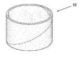
- FIG. 1is a perspective view of a ceramic article in hollow cylinder form
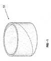
- FIG. 2is a perspective view of an uncured ceramic article in hollow cylinder form
- FIG. 3is a perspective view of a ceramic article in connecting rod form
- FIG. 4is a scanning electron image of a ceramic article at a magnification of 50 ⁇
- FIG. 5is a scanning electron image of a ceramic article at a magnification of 500 ⁇ ;
- FIG. 6is a perspective view of a multi-screw extruder for use in manufacturing the ceramic article.
- FIG. 7is a schematic side view of a dry-mixing apparatus, an agitated hopper, a feeder, and a screw arrangement of the multi-screw extruder.
- the present inventionincludes a ceramic article 10 , as set forth in FIGS. 1 and 3 , and a method of forming the ceramic article 10 .
- the ceramic article 10is typically used to form a metal matrix composite and is typically useful for automotive applications requiring excellent strength and wear resistance at elevated temperatures.
- the ceramic article 10 of the present inventioncan have applications beyond automotive applications, such as in aeronautical applications.
- the ceramic article 10comprises ceramic fibers 12 having an aspect ratio of greater than 3:1 and ceramic particles.
- the ceramic fibers 12are typically included in the ceramic article 10 to reduce the density, enhance metal infiltration, and optimize strength of the ceramic article 10 , as set forth in more detail below.
- the ceramic fibers 12typically comprise an element from period 2, 3, 4, or 5 of the periodic table of the elements.
- the ceramic fibers 12comprise aluminum, silicon, oxygen, zirconium, or carbon.
- the ceramic fibers 12are typically selected from the group of alumina-silica fibers, alumina-silica-zirconia fibers, carbon-graphite fibers, and combinations thereof. Carbon-graphite fibers are typically selected for applications requiring high strength.
- the ceramic fibers 12have an aspect ratio of greater than 3:1. In one embodiment, the ceramic fibers 12 have an aspect ratio of greater than or equal to 5:1. In another embodiment, the ceramic fibers 12 have an aspect ratio of greater than or equal to 10:1. It is to be appreciated that the term aspect ratio means a ratio of the longer dimension, i.e., length, of the ceramic fibers 12 to the shorter dimension, i.e., diameter, of the ceramic fibers 12 .
- the ceramic fibers 12typically have a length of from 5 to 500, more typically from 50 to 250 ⁇ m.
- the ceramic fibers 12typically have a diameter of from 1 to 20, more typically from 2 to 5 ⁇ m.
- ceramic fibers 12 having an aspect ratio of greater than 3:1decrease the density of the ceramic article 10 and optimize metal infiltration of the ceramic article 10 by spacing out the ceramic particles.
- the ceramic fibers 12define void space between the ceramic particles, which allows metal to flow between the ceramic particles and substantially infiltrate the ceramic article 10 during fabrication of the metal matrix composite.
- the ceramic fibers 12are substantially randomly oriented in three dimensions in the ceramic article 10 . It is to be appreciated that the term substantially means that greater than 90 out of 100 ceramic fibers 12 are randomly oriented in three dimensions in the ceramic article 10 . It is further to be appreciated that the term randomly oriented means that adjacent ceramic fibers 12 are disposed in different dimensions and that adjacent ceramic fibers 12 are free from a pattern of alignment. More specifically, adjacent ceramic fibers 12 oriented in different dimensions are typically present in the ceramic article 10 in an amount of greater than 85 parts by volume based on 100 parts by volume of the ceramic article 10 .
- adjacent ceramic fibers 12 oriented in the same dimensionare typically present in the ceramic article 10 in an amount of from 0.1 to 5 parts by volume based on 100 parts by volume of the ceramic article 10 .
- ceramic fibers 12 substantially randomly oriented in three dimensionsprovide the ceramic article 10 with uniform strength in three dimensions.
- the ceramic article 10 of the present inventionis typically free from fatigue and/or failure in a third, non-reinforced dimension as compared to ceramic articles 10 with ceramic fibers 12 oriented in only two dimensions.
- the ceramic fibers 12are typically substantially homogeneously dispersed in the ceramic article 10 . It is to be appreciated that the term substantially means greater than 90 out of 100 ceramic fibers 12 in the ceramic article 10 are homogeneously dispersed in the ceramic article 10 . Further, it is to be appreciated that the term homogeneously dispersed means that greater than 85% by volume of the ceramic fibers 12 in the ceramic article 10 are uniformly distributed on a scale of twice the diameter of the ceramic fiber. That is, greater than 85 out of 100 ceramic fibers 12 are spaced at least one ceramic fiber diameter away from an adjacent ceramic fiber. Without intending to be limited by theory, it is believed that ceramic fibers 12 that are substantially homogeneously dispersed in the ceramic article 10 provide the ceramic article 10 with uniform density and, consequently, uniform strength.
- the ceramic article 10is typically free from entanglements and conglomerations of ceramic fibers 12 that cause weak points that typically decrease strength and stiffness of ceramic articles 10 . Since the ceramic article 10 exhibits uniform density, it is typically unnecessary to add additional ceramic fibers 12 to the ceramic article 10 after formation to remedy inconsistent density, thereby minimizing production costs of the ceramic article 10 . Additionally, since the ceramic article 10 of the present invention is typically free from blockages caused by entanglements and conglomerations of ceramic fibers 12 , the ceramic article 10 of the present invention also minimizes infiltration blockages caused by entanglement and conglomeration and enables excellent metal infiltration for efficient production of metal matrix composites.
- An uncured ceramic article 14i.e., a ceramic article that has not been cured or sintered, is shown schematically in FIG. 2 .
- any liquid components of the uncured ceramic article 14typically burn off, and solids remain in the ceramic article 10 , as set forth in more detail below. That is, after curing or sintering, solids are typically present in the ceramic article 10 in an amount of from 20 to 50 parts by volume based on 100 parts by volume of the ceramic article 10 . Solids are more typically present in the ceramic article 10 in an amount of from 30 to 40 parts by volume based on 100 parts by volume of the ceramic article 10 .
- Airis typically present in the ceramic article 10 in an amount of from 50 to 80 parts by volume based on 100 parts by volume of the ceramic article 10 . Air is more typically present in the ceramic article 10 in an amount of from 60 to 70 parts by volume based on 100 parts by volume of the ceramic article 10 .
- the ceramic fibers 12are typically present in the uncured ceramic article 14 in an amount of from 5 to 25 parts by weight based on 100 parts by weight of solids in the uncured ceramic article 14 .
- the ceramic fibers 12typically remain as solids in the ceramic article 10 after curing or sintering. That is, the ceramic fibers 12 are typically present in the ceramic article 10 in an amount of from 3 to 15 parts by volume based on 100 parts by volume of the ceramic article 10 .
- the ceramic fibers 12are more typically present in the ceramic article 10 in an amount of from 5 to 10 parts by volume based on 100 parts by volume of the ceramic article 10 .
- a specific example of a ceramic fiberis an alumina-silica fiber, commercially available from Thermal Ceramics Inc. of Atlanta, Ga.
- the ceramic particlestypically provide the ceramic article 10 with excellent stiffness and wear resistance and typically comprise an element from period 2, 3, or 4 of the periodic table of the elements.
- the ceramic particlesmore typically comprise an element from period 2 or 3 of the periodic table of the elements.
- the ceramic particlescomprise silicon, oxygen, carbon, aluminum, or boron.
- the ceramic particlesare typically selected from the group of silicon carbide, alumina, boron carbide, and combinations thereof.
- the ceramic particlestypically each have a reference dimension of from 5 to 50 ⁇ m, more typically 5 to 30 ⁇ m.
- One skilled in the arttypically selects ceramic particles having a reference dimension of from 5 to 10 ⁇ m, i.e., a smaller ceramic particle, for applications requiring high strength and stiffness.
- one skilled in the arttypically selects ceramic particles having a reference dimension of from 10 to 30 ⁇ m, i.e., a larger ceramic particle, for applications requiring high wear resistance.
- One skilled in the arttypically combines smaller ceramic particles and larger ceramic particles for applications requiring high strength, stiffness, and wear resistance.
- the ceramic particlesare typically present in the uncured ceramic article 14 in an amount of from 50 to 75, more typically 60 to 70 parts by weight based on 100 parts by weight of solids in the uncured ceramic article 14 .
- the ceramic particlestypically remain as solids in the ceramic article 10 after curing or sintering. That is, the ceramic particles are typically present in the ceramic article 10 in an amount of from 15 to 30 parts by volume based on 100 parts by volume of the ceramic article 10 .
- the ceramic particlesare more typically present in the ceramic article 10 in an amount of from 22 to 28 parts by volume based on 100 parts by volume of the ceramic article 10 .
- a specific example of a ceramic particleis silicon carbide, commercially available from Washington Mills of Niagara Falls, N.Y.
- the ceramic article 10may further comprise a binder component. Without intending to be limited by theory, it is believed that the binder component provides the ceramic article 10 with strength.
- the binder componenttypically comprises an organic binder and an inorganic binder. More specifically, without intending to be limited by theory, it is believed that the organic binder provides the uncured ceramic article 14 with strength, whereas the inorganic binder provides a cured ceramic article, i.e., the ceramic article 10 , with strength.
- the organic binder of the binder componenttypically comprises a first component and a second component.
- the first componentis typically a starch. Without intending to be limited by theory, it is believed that the first component provides the uncured ceramic article 14 with strength and reduces adhesion of the second component.
- the first componentis typically present in the uncured ceramic article 14 in an amount of from 1 to 10 parts by weight based on 100 parts by weight of solids in the uncured ceramic article 14 .
- a specific example of a first componentis starch, commercially available as Westar 3+ Cationic Starch from Wesbond Corporation of Wilmington, Del.
- the second component of the organic bindertypically comprises a cellulose ether.
- the cellulose ethertypically exhibits reverse thermal gelation and provides lubricity during formation of the uncured ceramic article 14 . Without intending to be limited by theory, it is believed that the cellulose ether also typically provides surface activity, plasticity, uniform rheology, and uniform distribution of air during formation of the uncured ceramic article 14 . It is also believed that the cellulose ether also typically provides the uncured ceramic article 14 with strength.
- the cellulose etheris typically selected from the group of methyl cellulose, hydroxypropylmethylcellulose, hydroxybutylmethylcellulose, and combinations thereof.
- the second componentis typically present in the uncured ceramic article 14 in an amount of from 0.5 to 10 parts by weight based on 100 parts by weight of solids in the uncured ceramic article 14 .
- a suitable second componentis hydroxypropylmethylcellulose, commercially available under the trade name MethocelTM A4M from The Dow Chemical Company of Midland, Mich.
- the organic binderis typically present in the uncured ceramic article 14 in an amount of from 0.5 to 25 parts by weight based on 100 parts by weight of solids in the uncured ceramic article 14 .
- the inorganic binder of the binder componentis typically silica. Without intending to be limited by theory, it is believed that the inorganic binder provides the ceramic article 10 with strength.
- the inorganic binderis typically present in the uncured ceramic article 14 in an amount of from 2 to 10 parts by weight based on 100 parts by weight of solids in the uncured ceramic article 14 .
- the inorganic bindertypically remains as solids in the ceramic article 10 after curing or sintering. That is, the inorganic binder is typically present in the ceramic article 10 in an amount of from 2 to 5 parts by volume based on 100 parts by volume of the ceramic article 10 .
- a suitable inorganic binderis silica, commercially available under the trade name Bindzil 1440 Colloidal Silica from Wesbond Corporation of Wilmington, Del.
- the binder componentis typically present in the uncured ceramic article 14 in an amount of from 5 to 35 parts by weight based on 100 parts by weight of solids in the uncured ceramic article 14 .
- the uncured ceramic article 14may further comprise an additive component.
- the additive componenttypically comprises a filler.
- One skilled in the arttypically selects the filler to control the density of the ceramic article 10 . That is, the filler is typically included in the uncured ceramic article 14 according to the weight percent of ceramic particles and ceramic fibers 12 in the uncured ceramic article 14 .
- the fillertypically spaces out the ceramic particles and ceramic fibers 12 to provide the ceramic article 10 with desired density and to allow effective metal infiltration during formation of the metal matrix composite.
- the fillermay be any filler known in the art.
- the filleris typically selected to burn off during heating, i.e., curing or sintering, of the ceramic article 10 .
- the filleris typically selected from walnut shell flour, cellulose fiber, air, and combinations thereof. In one embodiment, the filler includes air to aid in curing the ceramic article 10 and to provide an open, porous ceramic article 10 , as set forth in FIG. 4 .
- the filleris typically present in the uncured ceramic article 14 in an amount of from 0.5 to 20 parts by weight based on 100 parts by weight of solids in the uncured ceramic article 14 .
- a suitable filleris walnut shell flour, commercially available under from Ecoshell of Corning, Calif.
- the additive componentmay further comprise an air entrainment agent.
- the air entrainment agentmay be any air entrainment agent known in the art that is compatible with the second component of the binder component.
- One skilled in the arttypically selects the air entrainment agent to increase air bubble content in the ceramic article 10 and stabilize air bubble size to effect uniform air bubble distribution in the ceramic article 10 .
- the air entrainment agentdecreases surface tension, optimizes dispersability, and contributes to the formation of fine, stable air bubbles to provide the open, porous ceramic article 10 that is receptive to metal infiltration, as set forth in FIG. 4 .
- the air entrainment agentis typically present in the uncured ceramic article 14 in an amount of from 0.01 to 1 part by weight based on 100 parts by weight of solids in the uncured ceramic article 14 .
- a suitable air entrainment agentis commercially available under the trade name Silipon® RN from Hercules of Wilmington, Del.
- the additive componentmay further comprise a surfactant.
- the surfactantmay be any known surfactant in the art that is compatible with the second component of the binder component. One skilled in the art typically selects the surfactant to lubricate the ceramic fibers 12 and ceramic particles.
- the surfactantis typically present in the uncured ceramic article 14 in an amount of from 0.01 to 1 part by weight based on 100 parts by weight of solids in the uncured ceramic article 14 .
- the additive componentmay further comprise a foam stabilizing agent.
- the foam stabilizing agentmay be any known foam stabilizing agent in the art that is compatible with the second component of the binder component. One skilled in the art typically selects the foam stabilizing agent to minimize the formation of undesired air bubbles in the uncured ceramic article 14 .
- the foam stabilizing agentis typically present in the uncured ceramic article 14 in an amount of from 0.01 to 1 part by weight based on 100 parts by weight of solids in the uncured ceramic article 14 .
- the additive componentis typically present in the uncured ceramic article 14 in an amount of from 5 to 30 parts by weight based on 100 parts by weight of solids in the uncured ceramic article 14 .
- the method of forming the ceramic article 10comprises the step of providing a composition comprising the ceramic particles and the ceramic fibers 12 having an aspect ratio of greater than 3:1.
- the compositionmay further comprise the binder component and the additive component.
- the step of providing the compositionis typically further defined as dry-mixing the ceramic particles and the ceramic fibers 12 to form the composition.
- a dry-mixing apparatusis schematically shown at 16 . Without intending to be limited by theory, it is believed that dry-mixing the ceramic particles and the ceramic fibers 12 optimizes other processing steps, e.g., extruding, and provides a uniform dispersion of the ceramic particles, the ceramic fibers 12 , the binder component, and the additive component in the composition. Dry-mixing also typically provides reaction time for the binder component and the additive component and avoids feeding individual component streams to processing equipment, thereby optimizing processing equipment throughput and minimizing processing equipment wear.
- Dry-mixingis typically further defined as batch tumble blending the ceramic particles and the ceramic fibers 12 in the dry-mixing apparatus 16 , i.e., a rotating vessel having at least two intermeshing flows. Without intending to be limited by theory, it is believed that the rotating vessel offers efficient and uniform solids mixing while optimizing energy consumption.
- the rotating vesselis typically rotated at about 60 Hz for from 1 to 3 minutes to dry-mix the composition.
- a suitable rotating vesselis commercially available under the trade name Rollo-Mixer® from Continental Products Corporation of Milwaukee, Wis.
- the methodmay further comprise the step of introducing water to the composition.
- Wateris typically introduced to the composition after dry-mixing the composition to provide the composition with a suitable consistency for other processing steps.
- Wateris typically introduced to the composition in an amount of from 5 to 30 parts by weight based on 100 parts by weight of the composition. In one embodiment, water is introduced to the composition in an amount of about 12 parts by weight based on 100 parts by weight of the composition.
- Wateris typically introduced to the composition as air-atomized particles via an air-atomizing nozzle for from 20 to 25 minutes to minimize solids agglomeration.
- the methodtypically further comprises the step of conveying the composition to an extruder.
- the extruderis schematically shown at 18 in FIGS. 6 and 7 .
- the step of conveyingcan include the step of agitating the composition.
- the compositionis typically agitated by loading the composition into an agitated hopper, which is schematically shown at 20 in FIG. 7 .
- the agitated hopper 20is free from corners in which the composition may aggregate.
- the agitated hopper 20may have a conical upper portion and a cylindrical lower portion.
- the agitated hopper 20is typically equipped with an agitator that sweeps the entire volume of the agitated hopper 20 to eliminate bridging of the composition in the agitated hopper 20 .
- the agitatortypically rotates at a speed and frequency designed to eliminate bridging without inducing shear to the composition.
- One skilled in the arttypically minimizes shear in the conveying step since the composition has both cohesive and adhesive properties and is susceptible to compaction.
- the agitated hopper 20typically provides a continuous supply of the composition to a feeder 22 comprising a vibratory tray 24 .
- the feeder 22typically controls the flow rate of the composition to the vibratory tray 24 , and the vibratory tray 24 typically distributes the composition into a curtain pattern for feeding to the extruder 18 .
- the extruder 18is preferably a multi-screw extruder 18 having at least three intermeshing screws 26 .
- the step of conveying the compositiontypically includes the step of feeding the composition to the multi-screw extruder 18 at a flow rate of from 36 to 136, more typically 45 to 90 kg/hr.
- the feeder 22is a belt-type feeder.
- the belt-type feedertypically includes a belt having a width of from 30 to 60 cm and a belt speed of from 0.006 to 1.9 m/s.
- the belt-type feedertypically minimizes shear, plasticization, and agglomeration of the composition during conveying.
- the compositionis extruded through the multi-screw extruder 18 having at least three intermeshing screws 26 to form an extrudate.
- the multi-screw extruder 18typically includes from 3 to 24, more typically from 10 to 12 screws 26 formed in a ring configuration. That is, the multi-screw extruder 18 is typically a ring extruder, as shown schematically in FIG. 7 .
- the at least three intermeshing screws 26are typically arranged in fixed positions in the ring, are typically geared to the same motor, and typically rotate at the same speed.
- the at least three intermeshing screws 26may be co-rotating or counter-rotating.
- the multi-screw extruder 18typically has a modular design and comprises solid barrels and/or combination barrels.
- the combination barrelstypically include ports 28 for injecting components or for venting volatile gases.
- One skilled in the arttypically selects a combination of solid barrels and combination barrels to provide desired processing characteristics of the multi-screw extruder 18 and desired physical properties of the extrudate.
- the multi-screw extruder 18may also include flow blocking flights for providing separate mixing processes in the multi-screw extruder 18 .
- the flow blocking flightsmay be flighted, and typically impede passing of the composition between sections of the multi-screw extruder 18 . It is to be appreciated that certain flow blocking flights can be removed for increasing the feeding capability of the multi-screw extruder 18 .
- the multi-screw extruder 18has elements with missing flights to increase an amount of composition present in the multi-screw extruder 18 . That is, certain flights are typically removed to a core of screw elements of the screw 26 to increase the feeding capability of the multi-screw extruder 18 .
- the multi-screw extruder 18typically has from 2 to 8, more typically from 4 to 6 mixing zones.
- the multi-screw extruder 18also typically has an L/D ratio of 18 to 56, more typically 20 to 44.
- a suitable multi-screw extruderis the 3+RingExtruder commercially available from Century, Inc. of Traverse City, Mich.
- the step of extrudingmay be further defined as rotating the at least three intermeshing screws 26 at from 20 to 1,200, more typically 100 to 400 rpm. As the at least three intermeshing screws 26 rotate, the composition is conveyed, mixed, and advanced through the multi-screw extruder 18 until the composition exits the multi-screw extruder 18 through a shaping die (not shown) as an extrudate.
- the multi-screw extruder 18typically elongates and shears the composition to provide distributive and dispersive mixing to both substantially randomly orient the ceramic fibers 12 in three dimensions and substantially homogeneously distribute dispersed ceramic fibers 12 in the ceramic article 10 .
- the step of extrudingtypically includes arranging adjacent ceramic fibers 12 in different dimensions so that adjacent ceramic fibers 12 arranged in different dimensions are present in the extrudate in an amount of greater than 85 parts by volume based on 100 parts by volume of the extrudate. That is, the multi-screw extruder 18 typically provides excellent elongational and low-intensity shear mixing that results in adjacent ceramic fibers 12 oriented in different dimensions in the extrudate.
- the methodmay further comprise the step of adding water or the binder component in liquid form to the composition while the composition is disposed within the multi-screw extruder 18 .
- Water and/or the binder component in liquid formare typically added to the composition via the ports 28 of the multi-screw extruder 18 to modify the physical properties of the extrudate and/or minimize wear of the multi-screw extruder 18 .
- the extrudateis heated to form the ceramic article 10 . That is, the extrudate is cured, i.e., sintered, to form the ceramic article 10 . It is to be appreciated that the extrudate may be manipulated to form a green form, i.e. the uncured ceramic article 14 , prior to heating the extrudate to form the ceramic article 10 . Specific parameters and processes for manipulating the extrudate to form the ceramic article 10 are set forth in co-pending U.S. Application Publication Nos. 2009/0309262 and 2009/0309252 and U.S. Pat. No. 7,793,703, the Applications of which are filed concurrently herewith.
- the extrudateis typically heated to effect both drying and baking of the ceramic article 10 .
- the extrudateis typically heated to a temperature of from 100 to 2,000° F.
- the extrudatemay be heated in an oven or by an open heat source.
- Specific parameters and processes for heating the uncured ceramic article 14are set forth in co-pending U.S. Patent Application Publication Nos. 2009/0309262 and 2009/0309252 and U.S. Pat. No. 7,793,703, the applications of which are filed concurrently herewith.
- the extrudateis typically dried to a temperature of from 70 to 200, more typically from 110 to 130° F. to bring the second component of the binder component to a gel point.
- the extrudateis typically baked at a temperature of from 450 to 700, more typically 475 to 525° F. for about 1 hour to burn off any organic binder and filler.
- the extrudateis typically cured or sintered at a temperature of from 1,600 to 2,000, more typically 1,700 to 1,900° F. for about 2 hours to set the inorganic binder and provide the ceramic article 10 with excellent strength at high temperatures.
- any liquid component of the uncured ceramic article 14typically burns off, and solids remain in the ceramic article 10 .
- solids in the ceramic article 10include the ceramic fibers 12 , the ceramic particles, and the inorganic binder of the binder component.
- solidsare typically present in the ceramic article 10 in an amount of from 20 to 50 parts by volume based on 100 parts by volume of the ceramic article 10 .
- Solidsare more typically present in the ceramic article 10 in an amount of from 30 to 40 parts by volume based on 100 parts by volume of the ceramic article 10 .
- Airis typically present in the ceramic article 10 in an amount of from 50 to 80 parts by volume based on 100 parts by volume of the ceramic article 10 .
- Airis more typically present in the ceramic article 10 in an amount of from 60 to 70 parts by volume based on 100 parts by volume of the ceramic article 10 .
- the step of heatingalso substantially randomly orients and substantially homogeneously disperses the ceramic fibers 12 in the extrudate. That is, the heating typically evaporates water, burns off any organic binder and filler, and sets the inorganic binder so as to define void space in the extrudate.
- the methodalso comprises the step of substantially randomly orienting the ceramic fibers 12 in three dimensions in the ceramic article 10 . That is, the step of substantially randomly orienting the ceramic fibers 12 includes arranging adjacent ceramic fibers 12 in different dimensions so that adjacent ceramic fibers 12 arranged in different dimensions are present in the ceramic article 10 in an amount of greater than 85 parts by volume based on 100 parts by volume of the ceramic article 10 . It is to be appreciated that the term substantially means that greater than 90 out of 100 ceramic fibers 12 are randomly oriented in three dimensions in the ceramic article 10 . It is further to be appreciated that the term randomly oriented means that adjacent ceramic fibers 12 are disposed in different dimensions and that adjacent ceramic fibers 12 are free from a pattern of alignment.
- the methodmay further comprise the step of substantially homogeneously dispersing the ceramic fibers 12 in the ceramic article 10 .
- substantiallymeans greater than 90 out of 100 ceramic fibers 12 in the ceramic article 10 are homogeneously dispersed in the ceramic article 10 .
- homogeneously dispersedmeans that greater than 85% by volume of the ceramic fibers 12 in the ceramic article 10 are uniformly distributed on a scale of twice the diameter of the ceramic fiber. That is, greater than 85 out of 100 ceramic fibers 12 are spaced at least one ceramic fiber diameter away from an adjacent ceramic fiber.
- the step of substantially randomly orienting the ceramic fibers 12 and the step of substantially homogeneously dispersing the ceramic fibers 12are typically simultaneous. That is, the multi-screw extruder 18 typically provides elongational and low-intensity shear mixing to both substantially randomly orient the ceramic fibers 12 in three dimensions and substantially homogeneously disperse the ceramic fibers 12 in the ceramic article 10 without excessive viscous energy dissipation and material heating. Without intending to be limited by theory, it is believed that effective dispersion of agglomerations of ceramic fibers 12 to individual ceramic fibers 12 and orientation of the ceramic fibers 12 typically minimizes infiltration blockages in the resulting ceramic article 10 caused by entanglement and conglomeration of the ceramic particles and ceramic fibers 12 . The resulting ceramic article 10 is typically free from entanglements and conglomerations of ceramic fibers 12 that cause weak points that typically decrease strength and stiffness of ceramic articles 10 .
- the step of substantially randomly orienting the ceramic fibers 12 and the step of heatingare typically simultaneous. Without intending to be limited by theory, it is believed that the step of heating also substantially randomly orients and substantially homogeneously disperses the ceramic fibers 12 in the ceramic article 10 . That is, the step of heating typically evaporates water, burns off of any organic binder and filler, and sets the inorganic binder so as to define void space in the ceramic article 10 .
- the step of substantially homogeneously dispersing the ceramic fibers 12 and the step of extrudingare typically simultaneous. That is, the step of substantially homogeneously dispersing agglomerations of ceramic fibers 12 to individual ceramic fibers 12 and the step of extruding are typically simultaneous.
- the multi-screw extruder 18typically provides elongational and low intensity shear mixing to substantially homogeneously disperse and distributes the ceramic fibers 12 in the extrudate.
- the ceramic article 10typically has a density of from 0.9 to 1.1 g/cm 3 and is typically suitable for applications requiring lightweight components.
- the ceramic article 10is a hollow cylinder, as set forth in FIG. 1 .
- the first embodimentis typically used to fabricate metal matrix composites to be used as drum brakes.
- the ceramic article 10 of the first embodimenttypically exhibits consistent density, even while including ceramic fibers 12 having an aspect ratio of greater than 3:1, and provides excellent wear resistance to metal matrix composites, e.g., drum brakes.
- the ceramic article 10is a connecting rod, as set forth in FIG. 3 .
- the ceramic article 10 of the second embodimenttypically exhibits excellent strength and stiffness.
- a compositionis formed according to the formulations listed in Table 1. The amounts in Table 1 are listed in pounds.
- Ceramic Particles A66.3 66.3 7.5 Ceramic Fibers B 13.3 13.3 1.5 Binder Component Organic Binder - First Component 5.0 5.0 0.5 C Organic Binder - Second 2.5 2.5 Component D Inorganic Binder E 5.5 5.5 0.5 Additive Component Filler F 7.5 7.5 Air Entrainment Agent G 0.01 0.01 Surfactant H 0.12 0.12 Total 100.2 100.2 10.0 Ceramic Particles A are silicon-carbide particles. Ceramic Fibers B are alumina-silica fibers having an aspect ratio of 10:1.
- Organic Binder - First Component Cis starch.
- Organic Binder - Second Component Dis hydroxypropylmethylcellulose.
- Inorganic Binder Eis silica.
- Filler Fis walnut shell flour.
- Air Entrainment Agent Gis a combination of sulfuric acid, sodium salts, and alkyl esters having from 12 to 18 carbon atoms.
- Surfactant His glycerin.
- Example 1a dry mixture of 66.3 pounds of Ceramic Particles A, 13.3 pounds of Ceramic Fibers B, a binder component comprising an organic binder including 5.0 pounds of First Component C and 2.5 pounds of Second Component D, and an additive component comprising 7.5 pounds of Filler F and 0.01 pounds of Air Entrainment Agent G is dry-mixed in a 5 ft 3 volume Mark VII RolloMixer® drum mixer, commercially available from Continental Products Corporation of Milwaukee, Wis., and rotated at 60 Hz for 2 minutes. Water, in a quantity of 12 parts by weight based on 100 parts of the dry mixture, and Surfactant H, in a quantity of 1 part by weight based on 100 parts of water, are added to the dry mixture over 25 minutes to form a premix composition of Example 1.
- the premix composition of Example 1is loaded into an agitated hopper.
- the agitated hopperdelivers the premix composition onto a belt-type feeder.
- the belt-type feedermeters the premix composition onto a vibratory pan that distributes the premix composition into a curtain pattern for feeding to a 3+ RingExtruder multi-screw extruder having 12 screws, commercially available from Century, Inc. of Traverse City, Mich.
- the multi-screw extruderhas 4 mixing zones and an L/D ratio of 32.
- the multi-screw extruderhas 1 feed barrel, 1 custom liquid injection barrel, 2 combination barrels, 5 solid barrels that are channeled for effective chilled liquid cooling, 12 screw shafts equipped with 6 missing-flight screw elements, 6 transition missing-flight screw elements, segmented mixing, and conventional conveying screw elements.
- the 12 screwsare rotated at from 100 to 150 rpm to mix and advance the composition through the multi-screw extruder 16 to form the extrudate.
- Comparative Example 2a dry mixture of 66.3 pounds of Ceramic Particles A, 13.3 pounds of Ceramic Fibers B, a binder component comprising an organic binder including 5.0 pounds of First Component C and 2.5 pounds of Second Component D, and an additive component comprising 7.5 pounds of Filler F and 0.01 pounds of Air Entrainment Agent G is dry-mixed in the 5 ft 3 volume Mark VII RolloMixer® drum mixer, and rotated at 60 Hz for 2 minutes. The water, in a quantity of 12 parts by weight based on 100 parts of the dry mixture, and Surfactant H, in a quantity of 1 part by weight based on 100 parts of water, are added to the dry mixture over 25 minutes to form a premix composition of Comparative Example 2.
- the premix composition of Example 2is loaded into an agitated hopper.
- the agitated hopperdelivers the premix composition onto a belt-type feeder.
- the belt-type feedermeters the premix composition onto a vibratory pan that distributes the premix composition into a curtain pattern for feeding to a twin-screw extruder having 2 screws, commercially available from Coperion Group GmbH of Stuttgart, Germany.
- twin-screw extruderAdditional water, in a quantity of 16.8 parts by weight based on 100 parts of the premix composition, and a solution of Inorganic Binder E in water, in a quantity of 13.75 parts by weight based on 100 parts of the premix composition, are added to the twin-screw extruder to form the composition of Example 2 that is extruded through the twin-screw extruder to form an extrudate.
- the twin-screw extruderhas 2 mixing zones and an L/D ratio of 32.
- the twin-screw extruderhas 1 feed barrel, 1 or more open barrels equipped with liquid injection adapter plugs, 3 to 5 solid barrels that are channeled for effective chilled liquid cooling, and 2 screw shafts with conventional conveying and mixing screw elements. The 2 screws are rotated at from 100 to 150 rpm to mix and advance the composition through the twin-screw extruder to form the extrudate.
- Comparative Example 3a dry mixture of 7.5 pounds of Ceramic Particles A, 1.5 pounds of Ceramic Fibers B are mixed with 50 gallons of water to form a premix.
- a binder componentcomprising an organic binder including 0.5 pounds of First Component C is added to the premix and mixed for 5 minutes to disperse First Component C.
- 0.5 pounds of Inorganic Binder Eis added to the premix and mixed for an additional 5 minutes to form a composition of Comparative Example 3.
- Ceramic articles of Example 4, Comparative Example 5, and Comparative Example 6are formed from the corresponding compositions of Example 1, Comparative Example 2, and Comparative Example 3 according to the processing parameters summarized in Table 2 below.
- the extrudate of the composition of Example 1is manipulated into a hollow cylinder according to processes as set forth in co-pending U.S. Patent Publication Nos. 2009/0309262 and 2009/0309252 and U.S. Pat. No. 7,793,703, the applications of which are filed concurrently herewith, to form a green form, i.e., an uncured ceramic article of Example 4.
- the uncured ceramic article of Example 4is dried to a first heating temperature of 140° F. for 48 hours, baked at a second heating temperature of 500° F. for 1 hour, and fired at a third heating temperature of 1,800° C. for 2 hours to form the ceramic article of Example 4.
- the extrudate of the composition of Comparative Example 2is manipulated into a hollow cylinder according to processes as set forth in co-pending U.S. Patent Publication Nos. 2009/0309262 and 2009/0309252 and U.S. Pat. No. 7,793,703, the applications of which are filed concurrently herewith, to form a green form, i.e., an uncured ceramic article of Comparative Example 5.
- the uncured ceramic article of Comparative Example 5is dried to a first heating temperature of 140° F. for 48 hours, baked at a second heating temperature of 500° F. for 1 hour, and fired at a third heating temperature of 1,800° F. for 2 hours to form the ceramic article of Comparative Example 5.
- the composition of Comparative Example 3is not extruded through an extruder to form an extrudate, but is rather vacuum formed into a hollow cylinder to form a green form, i.e., an uncured ceramic article of Comparative Example 6.
- the uncured ceramic article of Comparative Example 6is dried to a first heating temperature of 140° F., baked at a second heating temperature of 500° F. for 1 hour, and fired at a third heating temperature of 1,800° F. for 2 hours to form the ceramic article of Comparative Example 6.
- Scanning electron images of the ceramic articles of Example 4, Comparative Example 5, and Comparative Example 6are prepared with a Philips XL40 Environmental Scanning Electron Microscope (ESEM). The scanning electron images are evaluated visually to determine whether the ceramic articles of Example 4, Comparative Example 5, and Comparative Example 6 have substantially randomly oriented ceramic fibers in three dimensions and substantially homogeneously dispersed ceramic fibers. The amount of adjacent ceramic fibers oriented in the same and different dimensions present in the ceramic articles based on 100 parts by volume of the ceramic articles is determined by visually evaluating the scanning electron images of Example 4, Comparative Example 5, and Comparative Example 6.
- ESEMPhilips XL40 Environmental Scanning Electron Microscope
- the scanning electron imagesare also evaluated visually to determine whether the ceramic articles of Example 4, Comparative Example 5, and Comparative Example 6 have substantially consistent density at three positions, i.e., positions 1, 2, and 3, corresponding to an x-, y-, and z-dimension.
- the strength of the ceramic article in each dimensionis measured in accordance with ASTM C1424 Standard Test Method for Monotonic Compressive Strength of Advanced Ceramics at Ambient Temperature.
- the ceramic article of Example 4 formed from the composition of Example 1 that is extruded through the 3+RingExtruderhas substantially randomly oriented ceramic fibers and includes ceramic fibers having an aspect ratio of 10:1.
- the ceramic articles of Comparative Example 5 and Comparative Example 6, which are formed from the compositions of Comparative Examples 2 and 3, respectively, and which are not extruded through the 3+RingExtruderonly exhibit ceramic fibers primarily oriented in two dimensions. Consequently, the ceramic article of Example 4 exhibits uniform strength in three dimensions. In contrast, the ceramic articles of Comparative Example 5 and Comparative Example 6 do not exhibit uniform strength in three dimensions.
- the ceramic article of Example 4exhibits consistent density, even while including the ceramic fibers having an aspect ratio of 10:1 of the composition of Example 1.
- the ceramic articles of Comparative Example 5 and Comparative Example 6exhibit inconsistent density and comprise the ceramic fibers having an aspect ratio of 10:1 of Comparative Examples 2 and 3, respectively. Therefore, the ceramic article of Example 4 exhibits consistent density as a result of consistent mixing and uniform distribution of the ceramic particles and the ceramic fibers provided by extrusion of the composition of Example 1 through the 3+RingExtruder.
- the ceramic articles of Comparative Examples 5 and 6exhibit inconsistent mixing and nonuniform distribution of the ceramic particles and the ceramic fibers. Consequently, the ceramic articles of Comparative Example 5 and Comparative Example 6 wear more readily than the ceramic article of Example 4.
- the ceramic article of Example 4exhibits excellent strength and stiffness as compared to the ceramic articles of Comparative Examples 5 and 6. Also, as compared to the ceramic articles of Comparative Examples 5 and 6, the ceramic article of Example 4 has excellent porosity and minimal weak points and infiltration blockages caused by entanglement and conglomeration so as to enable excellent metal infiltration for efficient production of metal matrix composites.
- the ceramic article of Example 4comprises Second Component D, whereas the ceramic article of Comparative Example 6 is free from Second Component D.
- Second Component Dexhibits reverse thermal gelation and provides lubricity during formation of the ceramic article of Example 4.
- Second Component Dalso provides surface activity, plasticity, uniform rheology, and uniform distribution of air during formation of the ceramic article of Example 4, and provides an uncured ceramic article of Example 4 with strength.
- an uncured ceramic article of Comparative Example 6suffers from nonuniform distribution of air. As such, the uncured ceramic article of Comparative Example 6 exhibits less optimal strength.
- the ceramic article of Example 4comprises Filler F, Air Entrainment Agent G, and Surfactant H.
- the ceramic article of Comparative Example 6is free from Filler F, Air Entrainment Agent G, and Surfactant H. Filler F spaces out the Ceramic Particles A and Ceramic Fibers B of the composition of Example 1 to provide the ceramic article of Example 4 with excellent density to allow effective metal infiltration during formation of a metal matrix composite.
- the ceramic article of Comparative Example 6does not exhibit excellent density and is less desirable for use during formation of a metal matrix composite.
- Air Entrainment Agent Gincreases air bubble content in the ceramic article of Example 4 and stabilizes air bubble size to effect uniform air bubble distribution in the ceramic article of Example 4. Air Entrainment Agent G decreases surface tension, optimizes dispersability, and contributes to the formation of fine, stable air bubbles to provide the open, porous ceramic article of Example 4 that is receptive to metal infiltration. In contrast, the ceramic article of Comparative Example 6, which is free from Air Entrainment Agent H, is less porous. Therefore, the ceramic article of Comparative Example 6 is less receptive to metal infiltration when compared to the ceramic article of Example 4.
- Surfactant Glubricates Ceramic Particles A and Ceramic Fibers B of the composition of Example 1 during the formation of the ceramic article of Example 4.
- Ceramic Particles A and Ceramic Fibers B of the composition of Comparative Example 3which is free from Surfactant G, are less optimally lubricated during the formation of the ceramic article of Comparative Example 6.
- the ceramic article of Comparative Example 6does not exhibit excellent density and is less desirable for use during formation of a metal matrix composite.
Landscapes
- Engineering & Computer Science (AREA)
- Chemical & Material Sciences (AREA)
- Ceramic Engineering (AREA)
- Manufacturing & Machinery (AREA)
- Structural Engineering (AREA)
- Materials Engineering (AREA)
- Organic Chemistry (AREA)
- Inorganic Chemistry (AREA)
- Mechanical Engineering (AREA)
- Thermal Sciences (AREA)
- Physics & Mathematics (AREA)
- General Engineering & Computer Science (AREA)
- Chemical Kinetics & Catalysis (AREA)
- Metallurgy (AREA)
- Manufacture Of Alloys Or Alloy Compounds (AREA)
- Press-Shaping Or Shaping Using Conveyers (AREA)
- Compositions Of Oxide Ceramics (AREA)
- Extrusion Moulding Of Plastics Or The Like (AREA)
- Braking Arrangements (AREA)
Abstract
Description
| TABLE 1 |
| Composition Formulations |
| Comparative | Comparative | ||
| Ex. 1 | Ex. 2 | Ex. 3 | |
| Ceramic Particles A | 66.3 | 66.3 | 7.5 |
| Ceramic Fibers B | 13.3 | 13.3 | 1.5 |
| Binder Component | |||
| Organic Binder - First Component | 5.0 | 5.0 | 0.5 |
| C | |||
| Organic Binder - Second | 2.5 | 2.5 | |
| Component D | |||
| Inorganic Binder E | 5.5 | 5.5 | 0.5 |
| Additive Component | |||
| Filler F | 7.5 | 7.5 | |
| Air Entrainment Agent G | 0.01 | 0.01 | |
| Surfactant H | 0.12 | 0.12 | |
| Total | 100.2 | 100.2 | 10.0 |
| Ceramic Particles A are silicon-carbide particles. | |||
| Ceramic Fibers B are alumina-silica fibers having an aspect ratio of 10:1. | |||
| Organic Binder - First Component C is starch. | |||
| Organic Binder - Second Component D is hydroxypropylmethylcellulose. | |||
| Inorganic Binder E is silica. | |||
| Filler F is walnut shell flour. | |||
| Air Entrainment Agent G is a combination of sulfuric acid, sodium salts, and alkyl esters having from 12 to 18 carbon atoms. | |||
| Surfactant H is glycerin. | |||
| TABLE 2 |
| Ceramic Article Formation Parameters |
| Comparative | Comparative | ||
| Ex. 4 | Ex. 5 | Ex. 6 | |
| First Heating Temperature (° F.) | 140 | 140 | 140 |
| First Heating Duration (hours) | 48 | 48 | NA |
| Second Heating Temperature (° F.) | 500 | 500 | 500 |
| Second Heating Duration (hours) | 1 | 1 | 1 |
| Third Heating Temperature (° F.) | 1,800 | 1,800 | 1,800 |
| Third Heating Duration (hours) | 2 | 2 | 2 |
| TABLE 3 |
| Ceramic Article Properties |
| Comparative | Comparative | ||
| Ex. 4 | Ex. 5 | Ex. 6 | |
| Substantially randomly oriented | Yes | No | No |
| ceramic fibers in three dimensions | |||
| Amount of adjacent ceramic fibers | >85 | <85 | <85 |
| oriented in different dimensions | |||
| (wt %) | |||
| Amount of adjacent ceramic fibers | <5 | >5 | >5 |
| oriented in the same dimension | |||
| (wt %) | |||
| Substantially homogeneously | Yes | No | No |
| dispersed ceramic fibers | |||
| Consistent density at | Yes | No | No |
| and 3 (g/cm3) | |||
| Uniform strength in x-, y-, and z- | Yes | No | No |
| dimensions (MPa) | |||
Claims (20)
Priority Applications (1)
| Application Number | Priority Date | Filing Date | Title |
|---|---|---|---|
| US13/443,292US8455379B2 (en) | 2008-06-17 | 2012-04-10 | Ceramic article |
Applications Claiming Priority (3)
| Application Number | Priority Date | Filing Date | Title |
|---|---|---|---|
| US13228108P | 2008-06-17 | 2008-06-17 | |
| US12/174,982US8153541B2 (en) | 2008-06-17 | 2008-07-17 | Ceramic article |
| US13/443,292US8455379B2 (en) | 2008-06-17 | 2012-04-10 | Ceramic article |
Related Parent Applications (1)
| Application Number | Title | Priority Date | Filing Date |
|---|---|---|---|
| US12/174,982ContinuationUS8153541B2 (en) | 2008-06-17 | 2008-07-17 | Ceramic article |
Publications (2)
| Publication Number | Publication Date |
|---|---|
| US20120295784A1 US20120295784A1 (en) | 2012-11-22 |
| US8455379B2true US8455379B2 (en) | 2013-06-04 |
Family
ID=41413997
Family Applications (8)
| Application Number | Title | Priority Date | Filing Date |
|---|---|---|---|
| US12/174,986ActiveUS7793703B2 (en) | 2008-06-17 | 2008-07-17 | Method of manufacturing a metal matrix composite |
| US12/174,982Active2030-03-15US8153541B2 (en) | 2008-06-17 | 2008-07-17 | Ceramic article |
| US12/175,007AbandonedUS20090309262A1 (en) | 2008-06-17 | 2008-07-17 | Manufacturing apparatus and method for producing a preform |
| US12/882,159ActiveUS8016018B2 (en) | 2008-06-17 | 2010-09-14 | Method of manufacturing a metal matrix composite |
| US13/231,374Active2029-01-15US8550145B2 (en) | 2008-06-17 | 2011-09-13 | Method of manufacturing a metal matrix composite |
| US13/443,292ActiveUS8455379B2 (en) | 2008-06-17 | 2012-04-10 | Ceramic article |
| US13/925,588Active2028-09-05US9145938B2 (en) | 2008-06-17 | 2013-06-24 | Metal matrix composite |
| US14/867,440ActiveUS9803265B2 (en) | 2008-06-17 | 2015-09-28 | Metal matrix composite |
Family Applications Before (5)
| Application Number | Title | Priority Date | Filing Date |
|---|---|---|---|
| US12/174,986ActiveUS7793703B2 (en) | 2008-06-17 | 2008-07-17 | Method of manufacturing a metal matrix composite |
| US12/174,982Active2030-03-15US8153541B2 (en) | 2008-06-17 | 2008-07-17 | Ceramic article |
| US12/175,007AbandonedUS20090309262A1 (en) | 2008-06-17 | 2008-07-17 | Manufacturing apparatus and method for producing a preform |
| US12/882,159ActiveUS8016018B2 (en) | 2008-06-17 | 2010-09-14 | Method of manufacturing a metal matrix composite |
| US13/231,374Active2029-01-15US8550145B2 (en) | 2008-06-17 | 2011-09-13 | Method of manufacturing a metal matrix composite |
Family Applications After (2)
| Application Number | Title | Priority Date | Filing Date |
|---|---|---|---|
| US13/925,588Active2028-09-05US9145938B2 (en) | 2008-06-17 | 2013-06-24 | Metal matrix composite |
| US14/867,440ActiveUS9803265B2 (en) | 2008-06-17 | 2015-09-28 | Metal matrix composite |
Country Status (2)
| Country | Link |
|---|---|
| US (8) | US7793703B2 (en) |
| WO (1) | WO2009154728A2 (en) |
Cited By (9)
| Publication number | Priority date | Publication date | Assignee | Title |
|---|---|---|---|---|
| US9429202B2 (en) | 2012-05-02 | 2016-08-30 | Intellectuall Property Holdings LLC | Ceramic preform and method |
| US9550341B2 (en) | 2013-03-15 | 2017-01-24 | Rel, Inc. | Variable-density composite articles, preforms and methods |
| US9714686B2 (en) | 2014-10-20 | 2017-07-25 | Intellectual Property Holdings, Llc | Ceramic preform and method |
| US9803265B2 (en) | 2008-06-17 | 2017-10-31 | Gunite Corporation | Metal matrix composite |
| US10253833B2 (en) | 2017-06-30 | 2019-04-09 | Honda Motor Co., Ltd. | High performance disc brake rotor |
| US10357846B2 (en) | 2015-12-31 | 2019-07-23 | Intellectual Property Holdings, Llc | Metal matrix composite vehicle component and method |
| US10830296B2 (en) | 2017-04-21 | 2020-11-10 | Intellectual Property Holdings, Llc | Ceramic preform and method |
| US11187290B2 (en) | 2018-12-28 | 2021-11-30 | Honda Motor Co., Ltd. | Aluminum ceramic composite brake assembly |
| US11338360B2 (en) | 2016-02-04 | 2022-05-24 | Intellectual Property Holdings, Llc | Device and method for forming a metal matrix composite vehicle component |
Families Citing this family (16)
| Publication number | Priority date | Publication date | Assignee | Title |
|---|---|---|---|---|
| US20110290409A1 (en)* | 2010-05-28 | 2011-12-01 | Dekoron Unitherm LLC | Method and System for Forming an Extruded Jacket Over Elongated Objects |
| US9283734B2 (en) | 2010-05-28 | 2016-03-15 | Gunite Corporation | Manufacturing apparatus and method of forming a preform |
| US20130087420A1 (en)* | 2011-09-02 | 2013-04-11 | Century, Inc. | Brake rotor assembly |
| CN103171027B (en)* | 2011-12-22 | 2015-04-22 | 辽宁法库陶瓷工程技术研究中心 | Preparation method for circular type ceramic sprue cup in machine wheel forming mode |
| US10668651B2 (en) | 2012-03-22 | 2020-06-02 | Yazaki North America, Inc. | Pressurized rapid casting process |
| US10434568B2 (en) | 2012-04-12 | 2019-10-08 | Loukus Technologies, Inc. | Thermal isolation spray for casting articles |
| US9121463B2 (en) | 2012-11-28 | 2015-09-01 | Bendix Spicer Foundation Brake Llc | Nested composite brake drum |
| CN104439185B (en)* | 2014-12-09 | 2016-08-24 | 北京交通大学 | A kind of preparation method of composite wear piece |
| DE102015212017B4 (en) | 2015-06-29 | 2019-06-06 | Saf-Holland Gmbh | brake drum |
| CN105034152A (en)* | 2015-07-12 | 2015-11-11 | 东岳机械集团有限公司 | Steam-curing car connecting mechanism based on aerated concrete blocks |
| CN106196972B (en)* | 2016-08-19 | 2018-07-10 | 广西北流市智诚陶瓷自动化科技有限公司 | Drum type brake heat source rotates bowl base drying unit |
| US11001914B2 (en) | 2018-01-23 | 2021-05-11 | Dsc Materials Llc | Machinable metal matrix composite and method for making the same |
| US10851020B2 (en) | 2018-01-23 | 2020-12-01 | Dsc Materials Llc | Machinable metal matrix composite and method for making the same |
| JP2019211002A (en)* | 2018-06-05 | 2019-12-12 | 株式会社ジェイテクト | Thrust needle bearing |
| CN113478638B (en)* | 2021-05-27 | 2023-02-28 | 中铁十九局集团第三工程有限公司 | Apparatus for manufacturing assembled reinforced concrete pipe |
| US20240051195A1 (en)* | 2021-12-23 | 2024-02-15 | Arris Composites Inc. | Apparatus and Method for Controlling the Alignment of Fiber Loops in Compression Molded Articles |
Citations (113)
| Publication number | Priority date | Publication date | Assignee | Title |
|---|---|---|---|---|
| US2262242A (en) | 1938-03-24 | 1941-11-11 | Frank J Lenox | Container |
| US3002433A (en) | 1958-01-10 | 1961-10-03 | Sonoco Products Co | Spiral wound paper tube having seamless outer surface |
| US3005259A (en) | 1958-11-24 | 1961-10-24 | Chrysler Corp | Method of making brake drums |
| US3007553A (en) | 1958-05-19 | 1961-11-07 | Keisey Hayes Company | Brake drum |
| US3066766A (en) | 1961-04-04 | 1962-12-04 | Robert N Minor | Quick change brake lining |
| US3090114A (en) | 1958-12-29 | 1963-05-21 | Kelsey Hayes Co | Method of making a brake drum |
| US3126306A (en) | 1964-03-24 | Attoxj | ||
| US3697718A (en) | 1970-02-13 | 1972-10-10 | Mannesmann Ag | Method for manufacturing welded pipes or tubes with helical seam |
| US3793204A (en) | 1972-07-28 | 1974-02-19 | Atomic Energy Commission | Thermal insulation |
| US3841448A (en) | 1973-06-14 | 1974-10-15 | Budd Co | Reinforced brake drum |
| US3932568A (en) | 1973-06-26 | 1976-01-13 | Friction Products Inc. | High-energy brake and brake components |
| US4026690A (en) | 1976-06-22 | 1977-05-31 | J.C. Baxter Co. | Forming tube for winding glass fibers and method for using same |
| US4141481A (en) | 1975-04-23 | 1979-02-27 | Brunswick Corporation | Method and apparatus for making helically seamed tubing |
| US4266638A (en) | 1977-12-08 | 1981-05-12 | Ford Motor Company | Composite brake drum |
| US4312672A (en) | 1979-04-25 | 1982-01-26 | Metzeler Kautschuk Gmbh | Release agent for removing plastics, especially polyurethane plastics from molds |
| US4331628A (en) | 1976-07-28 | 1982-05-25 | Feldmuhle Anlagen-und Produktionsgesellschaft mbH | Method for preparing a finished concrete part |
| US4448833A (en) | 1981-06-16 | 1984-05-15 | Nippondenso Co., Ltd. | Porous ceramic body and a method of manufacturing the same |
| US4577734A (en) | 1984-01-20 | 1986-03-25 | Rockwell International Corporation | Brake drum |
| US4679681A (en) | 1984-04-05 | 1987-07-14 | Kolbenschmidt Ag | Synchronizing ring and process of manufacturing the same |
| US4702877A (en) | 1985-12-31 | 1987-10-27 | Davis Jr Lindsey B | Method for molding concrete blocks or bricks |
| US4710252A (en) | 1984-10-22 | 1987-12-01 | Steeltin Can Corporation | Method and machine for convolute or spiral winding of composite materials |
| US4909301A (en) | 1988-10-14 | 1990-03-20 | Sundstrand Corporation | Method of making a bearing |
| US4935178A (en)* | 1986-06-24 | 1990-06-19 | General Signal Corporation | Method of making refractory fiber products |
| US5002836A (en)* | 1985-06-21 | 1991-03-26 | Imperial Chemical Industries Plc | Fiber-reinforced metal matrix composites |
| US5068076A (en) | 1988-07-28 | 1991-11-26 | Libbey-Owens-Ford Co. | Method of forming an encapsulated glazing unit |
| US5104598A (en) | 1989-12-22 | 1992-04-14 | Didier-Werke Ag | Process for producing light-weight fiber brick |
| US5108964A (en) | 1989-02-15 | 1992-04-28 | Technical Ceramics Laboratories, Inc. | Shaped bodies containing short inorganic fibers or whiskers and methods of forming such bodies |
| US5112553A (en) | 1989-09-04 | 1992-05-12 | Polyplastics Co., Ltd. | Improvement in injection molded articles having three dimensional surfaces |
| US5153057A (en) | 1989-02-15 | 1992-10-06 | Technical Ceramics Laboratories, Inc. | Shaped bodies containing short inorganic fibers or whiskers within a metal matrix |
| US5188787A (en) | 1988-01-25 | 1993-02-23 | Du Pont Canada Inc. | Process for the injection moulding of multi-layered articles |
| US5299667A (en) | 1989-07-22 | 1994-04-05 | Dunlop Limited, A British Company | Carbon composite laminated structure |
| US5325941A (en) | 1990-09-11 | 1994-07-05 | Farinacci Michael F | Composite brake rotors and clutches |
| US5342463A (en) | 1991-10-28 | 1994-08-30 | Centro Sviluppo Settori Impiego S.R.L. | Process for producing shaped articles by starting from reinforced thermoplastic sheets |
| US5382399A (en) | 1991-07-26 | 1995-01-17 | Compagnie Plastic Omnium | Method for the production of fluorinated resin tubes, particularly of polytetrafluoroethylene |
| US5433511A (en) | 1993-10-07 | 1995-07-18 | Hayes Wheels International, Inc. | Cast wheel reinforced with a metal matrix composite |
| EP0704414A1 (en) | 1994-09-23 | 1996-04-03 | Mitsubishi Kasei Corporation | Alumina fiber granules, process for producing the granules and a process for producing a porous article using the granules |
| US5511603A (en) | 1993-03-26 | 1996-04-30 | Chesapeake Composites Corporation | Machinable metal-matrix composite and liquid metal infiltration process for making same |
| US5535857A (en) | 1993-11-25 | 1996-07-16 | Gkn Sankey Limited | Brake disc and method for its production |
| US5574957A (en) | 1994-02-02 | 1996-11-12 | Corning Incorporated | Method of encasing a structure in metal |
| US5586963A (en) | 1994-06-27 | 1996-12-24 | Sonoco Products Company | Single-ply paperboard tube and method of forming same |
| US5591292A (en) | 1992-04-30 | 1997-01-07 | Oy Kwh Pipe Ab | Welding method in the manufacture of a spirally wound tube and a welding head for performing the method |
| US5637168A (en) | 1994-05-27 | 1997-06-10 | Steward Plastics, Inc. | Apparatus and method for making flexible tubing with helically wound heating conductor |
| US5662145A (en) | 1993-12-03 | 1997-09-02 | Quality Tubing, Inc. | Dual bias weld for continuous coiled tubing |
| US5798013A (en) | 1993-08-06 | 1998-08-25 | Brandenburger Patentverwertungsgesellschaft Des Burgerlichen Rechts | Method and apparatus for producing a tubular lining hose |
| US5876659A (en) | 1993-06-25 | 1999-03-02 | Hitachi, Ltd. | Process for producing fiber reinforced composite |
| US5878849A (en) | 1996-05-02 | 1999-03-09 | The Dow Chemical Company | Ceramic metal composite brake components and manufacture thereof |
| US5900194A (en) | 1996-12-27 | 1999-05-04 | Wasatch Technologies Corporation | Method for removing mandrels from composite tubes of substantial length |
| US5919493A (en) | 1992-10-13 | 1999-07-06 | Ushers, Inc. | Apparatus for producing shaped articles |
| US5957251A (en) | 1996-05-02 | 1999-09-28 | The Dow Chemical Company | Brake or clutch components having a ceramic-metal composite friction material |
| US6042935A (en) | 1994-10-28 | 2000-03-28 | Deutsche Forschungsanstalt Fuer Luft-Ung Raumfahrt E.V. | Friction element |
| US6169048B1 (en) | 1997-12-22 | 2001-01-02 | Sandvik Ab | Method of manufacturing whisker-reinforced ceramics |
| US6180258B1 (en) | 1997-06-04 | 2001-01-30 | Chesapeake Composites Corporation | Metal-matrix composites and method for making such composites |
| US6180037B1 (en) | 1992-08-11 | 2001-01-30 | E. Khashoggi Industries, Llc | Methods for the manufacture of sheets having a highly inorganically filled organic polymer matrix |
| US20010000333A1 (en) | 1997-07-10 | 2001-04-19 | Honda Giken Kogyo Kabushiki Kaisha | Preform and production method therefor |
| US6306235B1 (en) | 1997-10-16 | 2001-10-23 | Nomaco, Inc. | Spiral formed products and method of manufacture |
| US6309743B1 (en) | 1998-09-30 | 2001-10-30 | Mazda Motor Corporation | Partially composite lightweight metal product and preform for producing the same |
| US6344160B1 (en) | 1996-09-17 | 2002-02-05 | Compcast Technologies, Llc | Method for molding composite structural plastic and objects molded thereby |
| US6386341B1 (en) | 1999-05-31 | 2002-05-14 | Dr. Ing. H.C.F. Porsche Aktiengesellschaft | Brake disk made of a fiber-reinforced material |
| US6413069B2 (en) | 1994-04-25 | 2002-07-02 | Dai Nippon Printing Co., Ltd. | Apparatus for forming pattern onto article during injection molding |
| US6458466B1 (en) | 1998-04-24 | 2002-10-01 | Dow Global Technologies Inc. | Brake or clutch components having a ceramic-metal composite friction material |
| US6460597B1 (en) | 1995-06-21 | 2002-10-08 | 3M Innovative Properties Company | Method of making fiber reinforced aluminum matrix composite |
| US6488802B1 (en) | 1998-09-30 | 2002-12-03 | Jerry C. Levingston | Pipe extrusion process |
| US6503441B2 (en) | 2001-05-30 | 2003-01-07 | General Electric Company | Method for producing melt-infiltrated ceramic composites using formed supports |
| US6530458B1 (en) | 1996-02-28 | 2003-03-11 | Rau, Iii Charles B. | Lightweight reinforced brake drum and method for making lightweight reinforced brake drum |
| US6539644B1 (en) | 2001-09-15 | 2003-04-01 | Corning Incorporated | Drying of ceramic honeycomb substrates |
| US6548000B1 (en) | 1999-01-21 | 2003-04-15 | Companie Plastic Omnium | Method of manufacturing a molded piece of plastic that is painted in part, and pieces obtained by implementing the method |
| US20030092557A1 (en) | 2000-11-07 | 2003-05-15 | Wilfried Aichele | Ceramic composite |
| US20030180538A1 (en) | 2002-03-19 | 2003-09-25 | Gray Paul E. | Melt-infiltrated pitch-pan preforms |
| US20030180172A1 (en) | 2002-03-18 | 2003-09-25 | Teruyuki Oda | Preform structure and method of manufacturing preform and bearing housing structure having the preform formed into metal matrix composite of cylinder block |
| US20040035547A1 (en) | 2002-08-20 | 2004-02-26 | 3M Innovative Properties Company | Metal matrix composites, and methods for making the same |
| WO2004018718A1 (en) | 2002-08-20 | 2004-03-04 | 3M Innovative Properties Company | Metal matrix composites, and methods for making the same |
| US20040048095A1 (en) | 2001-07-13 | 2004-03-11 | Crocco Frank Victor | Reinforced aluminum metal composite carrier |
| US20040118547A1 (en) | 2002-12-23 | 2004-06-24 | Chesapeake Composites Corporation | Machineable metal-matrix composite and method for making the same |
| US20040132607A1 (en) | 2003-01-08 | 2004-07-08 | 3M Innovative Properties Company | Ceramic fiber composite and method for making the same |
| US20040141405A1 (en) | 2001-05-09 | 2004-07-22 | Blach Josef A. | Homogenizing and/or dispersing device comprising endless screws |
| US20040145095A1 (en) | 2003-01-24 | 2004-07-29 | Vec Technology, Inc. | Method of making a composite molded article |
| US20040146709A1 (en) | 2003-01-24 | 2004-07-29 | Eagle Industry Co., Ltd. | Sliding element for seals and their process of manufacturing |
| US20040173291A1 (en) | 2002-11-18 | 2004-09-09 | Rozenoyer Boris Y. | Metal matrix composite |
| US6796365B1 (en) | 2000-07-14 | 2004-09-28 | 3M Innovative Properties Company | Method of making aluminum matrix composite wire |
| US20050011591A1 (en) | 2002-06-13 | 2005-01-20 | Murty Gollapudi S. | Metal matrix composites with intermettalic reinforcements |
| US20050183909A1 (en) | 2004-01-21 | 2005-08-25 | Rau Charles B.Iii | Disc brake rotor assembly and method for producing same |
| US20050217950A1 (en) | 2004-03-11 | 2005-10-06 | Benmaxx, Llc | Lightweight reinforced brake drum and method for making same |
| US20050241434A1 (en) | 2004-03-25 | 2005-11-03 | Mx Composites Ab | Use of a transmission component of a metal matrix composite (MMC) material |
| US20050253302A1 (en) | 2002-03-12 | 2005-11-17 | Degussa Ag | Release agents comprising hydrophobic, nanoscalar particles, and the use of these mold release agents |
| US20050260408A1 (en) | 2004-05-19 | 2005-11-24 | Prem Anand | Rotatable head for forming spiral extrusions |
| US6989067B2 (en) | 2003-04-14 | 2006-01-24 | Roller Equipment Manufacturing Co., Inc. | Method and apparatus for application of material to core |
| US20060027429A1 (en) | 2004-08-04 | 2006-02-09 | Donn Knight | Composite brake drum |
| US20060057356A1 (en) | 2004-06-15 | 2006-03-16 | Honda Motor Co., Ltd. | Ceramic molded body and metal matrix composite |
| US20060062986A1 (en) | 2004-05-24 | 2006-03-23 | Nissin Kogyo Co., Ltd. | Carbon fiber composite material and method of producing the same, carbon fiber-metal composite material and method of producing the same, and carbon fiber-nonmetal composite material and method of producing the same |
| US7052637B1 (en) | 2000-05-17 | 2006-05-30 | Saab Ab | Manufacturing of components for valve mechanisms for internal combustion engines |
| US7080935B2 (en) | 2001-10-11 | 2006-07-25 | Buhler Ag | Multi-screw extruder |
| US7126257B2 (en) | 2003-05-23 | 2006-10-24 | Virginia Tech Intellectual Properties, Inc. | Piezoelectric ceramic-reinforced metal matrix composites |
| WO2006113762A2 (en) | 2005-04-18 | 2006-10-26 | Benmaxx, Llc | Improved cast wheel comprising pre-form reinforcement in high-density die casting |
| US20060243421A1 (en) | 2005-04-29 | 2006-11-02 | United States Of America, Represented By Secretary Of The U.S. Army | Soluble casting core for metal matrix composite components and method of producing thereof |
| US20060263574A1 (en) | 2004-10-08 | 2006-11-23 | Ibiden Co., Ltd. | Honeycomb structure and method for manufacturing the same |
| US20060293454A1 (en) | 2005-06-27 | 2006-12-28 | Nadella Hari P | Dynamic vulcanization process for preparing thermoplastic elastomers |
| US20060293457A1 (en) | 2005-06-27 | 2006-12-28 | Nadella Hari P | Preparation of thermoplastic elastomers by dynamic vulcanization in multi-screw extruders |
| US7163653B2 (en) | 2000-10-18 | 2007-01-16 | Menzolit Fibron Gmbh | Method for producing ceramic brake disks, with an insert in the green body before the pyrolysis |
| US7175796B2 (en) | 2000-09-29 | 2007-02-13 | Menzolit-Fibron Gmbh | Method for producing ceramic brake disks from bmc |
| WO2007033378A1 (en) | 2005-09-14 | 2007-03-22 | Benmaxx, Llc | Lightweight reinforced castings and method for making same |
| US7208108B2 (en) | 2001-12-07 | 2007-04-24 | Ngk Insulators, Ltd. | Method for producing porous ceramic article |
| US7216746B2 (en) | 2004-02-03 | 2007-05-15 | Nissin Kogyo Co., Ltd. | Brake drum and process for manufacturing the same |
| US20070152364A1 (en) | 2005-11-16 | 2007-07-05 | Bilal Zuberi | Process for extruding a porous substrate |
| US7290506B2 (en) | 2004-02-09 | 2007-11-06 | Benmaxx, Llc | Fluid-cooled cylinder liner |
| US20080135359A1 (en) | 2006-12-11 | 2008-06-12 | Basirico John T | Brake rotor with ceramic matrix composite friction surface plates |
| US20080220234A1 (en) | 2005-04-07 | 2008-09-11 | Snt Co., Ltd | Method of Preparing Wear-Resistant Coating Layer Comprising Metal Matrix Composite and Coating Layer Prepared Thereby |
| US20080264595A1 (en) | 2004-04-08 | 2008-10-30 | Roger Stanley Bushby | Liquid Pressure Forming |
| US7459110B2 (en) | 2003-12-04 | 2008-12-02 | Ceramtec Ag | Porous fiber-ceramic composite |
| US20080310989A1 (en) | 2005-03-14 | 2008-12-18 | Forges De Bologne | Method for Preparing Metal-Matrix Composite and Device for Implementing Said Method |
| US20090312174A1 (en) | 2008-06-17 | 2009-12-17 | Century, Inc. | Ceramic article |
| US20100001231A1 (en) | 2006-12-01 | 2010-01-07 | Ftf, Llc | Variable-density preforms |
| US20100187053A1 (en) | 2007-07-31 | 2010-07-29 | Daimler Ag | Disk brake |
| US20120183707A1 (en)* | 2010-05-28 | 2012-07-19 | Neil Anderson | Manufacturing Apparatus And Method Of Forming A Preform |
Family Cites Families (19)
| Publication number | Priority date | Publication date | Assignee | Title |
|---|---|---|---|---|
| US3608170A (en)* | 1969-04-14 | 1971-09-28 | Abex Corp | Metal impregnated composite casting method |
| US3794538A (en)* | 1970-07-13 | 1974-02-26 | Goodyear Tire & Rubber | Method of making a rolling lobe diaphragm |
| DE2350841C3 (en)* | 1972-11-20 | 1978-12-14 | Deutsche Semperit Gmbh, 8000 Muenchen | Method for butt-joining layers of plastically deformable material, in particular rubber-coated steel wire layers |
| JPS60234762A (en) | 1984-05-03 | 1985-11-21 | Toyoda Autom Loom Works Ltd | Method and device for producing fiber reinforced molding |
| FR2567069B1 (en)* | 1984-07-03 | 1986-12-05 | Lhomme Sa | PROCESS AND DEVICE FOR MANUFACTURING A CALIBERED TUBE WITH VERY LOW SURFACE ROUGHNESS AND HIGH DIMENSIONAL STABILITY |
| JPS61166934A (en)* | 1985-01-17 | 1986-07-28 | Toyota Motor Corp | Short fiber molded article for composite material production and method for producing the same |
| JPS61293649A (en) | 1985-06-20 | 1986-12-24 | Akebono Brake Res & Dev Center Ltd | Casting method for fiber-reinforced caliper |
| FR2584805B1 (en)* | 1985-07-12 | 1989-07-13 | Elect Meca Et Const | IMPROVEMENT IN DRYING AND COOKING PLANTS FOR CERAMIC PRODUCTS |
| US5199481A (en)* | 1988-10-17 | 1993-04-06 | Chrysler Corp | Method of producing reinforced composite materials |
| US5121329A (en)* | 1989-10-30 | 1992-06-09 | Stratasys, Inc. | Apparatus and method for creating three-dimensional objects |
| US5234045A (en) | 1991-09-30 | 1993-08-10 | Aluminum Company Of America | Method of squeeze-casting a complex metal matrix composite in a shell-mold cushioned by molten metal |
| KR930008725A (en)* | 1991-10-01 | 1993-05-21 | 프레데릭 얀 스미트 | Apparatus for reproducing digital signals from tracks on magnetic recording carriers |
| JPH06340475A (en) | 1992-12-07 | 1994-12-13 | Toshiba Corp | Fiber reinforced ceramic composite material and its production |
| US5782324A (en)* | 1995-12-27 | 1998-07-21 | Dayton Walther Corporation | Composite brake drum and method for producing same |
| JPH109294A (en)* | 1996-06-19 | 1998-01-13 | Sumitomo Electric Ind Ltd | Roller brake for motorcycle and method of manufacturing the same |
| ES2283413T3 (en)* | 2000-05-29 | 2007-11-01 | Honda Giken Kogyo Kabushiki Kaisha | BRAKE DRUM AND PRODUCTION PROCEDURE OF THIS DRUM. |
| GB0029954D0 (en)* | 2000-12-08 | 2001-01-24 | Caradon Mira Ltd | Improvements in or relating to metal finishes |
| US7836938B2 (en)* | 2007-09-24 | 2010-11-23 | Gm Global Technology Operations, Inc. | Insert with tabs and damped products and methods of making the same |
| US20090309252A1 (en) | 2008-06-17 | 2009-12-17 | Century, Inc. | Method of controlling evaporation of a fluid in an article |
- 2008
- 2008-07-17USUS12/174,986patent/US7793703B2/enactiveActive
- 2008-07-17USUS12/174,982patent/US8153541B2/enactiveActive
- 2008-07-17USUS12/175,007patent/US20090309262A1/ennot_activeAbandoned
- 2009
- 2009-06-16WOPCT/US2009/003588patent/WO2009154728A2/enactiveApplication Filing
- 2010
- 2010-09-14USUS12/882,159patent/US8016018B2/enactiveActive
- 2011
- 2011-09-13USUS13/231,374patent/US8550145B2/enactiveActive
- 2012
- 2012-04-10USUS13/443,292patent/US8455379B2/enactiveActive
- 2013
- 2013-06-24USUS13/925,588patent/US9145938B2/enactiveActive
- 2015
- 2015-09-28USUS14/867,440patent/US9803265B2/enactiveActive
Patent Citations (125)
| Publication number | Priority date | Publication date | Assignee | Title |
|---|---|---|---|---|
| US3126306A (en) | 1964-03-24 | Attoxj | ||
| US2262242A (en) | 1938-03-24 | 1941-11-11 | Frank J Lenox | Container |
| US3002433A (en) | 1958-01-10 | 1961-10-03 | Sonoco Products Co | Spiral wound paper tube having seamless outer surface |
| US3007553A (en) | 1958-05-19 | 1961-11-07 | Keisey Hayes Company | Brake drum |
| US3005259A (en) | 1958-11-24 | 1961-10-24 | Chrysler Corp | Method of making brake drums |
| US3090114A (en) | 1958-12-29 | 1963-05-21 | Kelsey Hayes Co | Method of making a brake drum |
| US3066766A (en) | 1961-04-04 | 1962-12-04 | Robert N Minor | Quick change brake lining |
| US3697718A (en) | 1970-02-13 | 1972-10-10 | Mannesmann Ag | Method for manufacturing welded pipes or tubes with helical seam |
| US3793204A (en) | 1972-07-28 | 1974-02-19 | Atomic Energy Commission | Thermal insulation |
| US3841448A (en) | 1973-06-14 | 1974-10-15 | Budd Co | Reinforced brake drum |
| US3932568A (en) | 1973-06-26 | 1976-01-13 | Friction Products Inc. | High-energy brake and brake components |
| US4141481A (en) | 1975-04-23 | 1979-02-27 | Brunswick Corporation | Method and apparatus for making helically seamed tubing |
| US4026690A (en) | 1976-06-22 | 1977-05-31 | J.C. Baxter Co. | Forming tube for winding glass fibers and method for using same |
| US4331628A (en) | 1976-07-28 | 1982-05-25 | Feldmuhle Anlagen-und Produktionsgesellschaft mbH | Method for preparing a finished concrete part |
| US4266638A (en) | 1977-12-08 | 1981-05-12 | Ford Motor Company | Composite brake drum |
| US4312672A (en) | 1979-04-25 | 1982-01-26 | Metzeler Kautschuk Gmbh | Release agent for removing plastics, especially polyurethane plastics from molds |
| US4448833A (en) | 1981-06-16 | 1984-05-15 | Nippondenso Co., Ltd. | Porous ceramic body and a method of manufacturing the same |
| US4577734A (en) | 1984-01-20 | 1986-03-25 | Rockwell International Corporation | Brake drum |
| US4679681A (en) | 1984-04-05 | 1987-07-14 | Kolbenschmidt Ag | Synchronizing ring and process of manufacturing the same |
| US4710252A (en) | 1984-10-22 | 1987-12-01 | Steeltin Can Corporation | Method and machine for convolute or spiral winding of composite materials |
| US5002836A (en)* | 1985-06-21 | 1991-03-26 | Imperial Chemical Industries Plc | Fiber-reinforced metal matrix composites |
| US4702877A (en) | 1985-12-31 | 1987-10-27 | Davis Jr Lindsey B | Method for molding concrete blocks or bricks |
| US4935178A (en)* | 1986-06-24 | 1990-06-19 | General Signal Corporation | Method of making refractory fiber products |
| US5188787A (en) | 1988-01-25 | 1993-02-23 | Du Pont Canada Inc. | Process for the injection moulding of multi-layered articles |
| US5068076A (en) | 1988-07-28 | 1991-11-26 | Libbey-Owens-Ford Co. | Method of forming an encapsulated glazing unit |
| US4909301A (en) | 1988-10-14 | 1990-03-20 | Sundstrand Corporation | Method of making a bearing |
| US5335712A (en) | 1989-02-15 | 1994-08-09 | Technical Ceramics Laboratories, Inc. | Shaped bodies containing short inorganic fibers or whiskers and methods of forming such bodies |
| US5108964A (en) | 1989-02-15 | 1992-04-28 | Technical Ceramics Laboratories, Inc. | Shaped bodies containing short inorganic fibers or whiskers and methods of forming such bodies |
| US5529620A (en)* | 1989-02-15 | 1996-06-25 | Technical Ceramics Laboratories, Inc. | Shaped bodies containing short inorganic fibers or whiskers and methods of forming such bodies |
| US5153057A (en) | 1989-02-15 | 1992-10-06 | Technical Ceramics Laboratories, Inc. | Shaped bodies containing short inorganic fibers or whiskers within a metal matrix |
| US5458181A (en) | 1989-02-15 | 1995-10-17 | Technical Ceramics Laboratories, Inc. | Shaped bodies containing short inorganic fibers or whiskers and methods of forming such bodies |
| US5299667A (en) | 1989-07-22 | 1994-04-05 | Dunlop Limited, A British Company | Carbon composite laminated structure |
| US5112553A (en) | 1989-09-04 | 1992-05-12 | Polyplastics Co., Ltd. | Improvement in injection molded articles having three dimensional surfaces |
| US5104598A (en) | 1989-12-22 | 1992-04-14 | Didier-Werke Ag | Process for producing light-weight fiber brick |
| US5325941A (en) | 1990-09-11 | 1994-07-05 | Farinacci Michael F | Composite brake rotors and clutches |
| US5382399A (en) | 1991-07-26 | 1995-01-17 | Compagnie Plastic Omnium | Method for the production of fluorinated resin tubes, particularly of polytetrafluoroethylene |
| US5342463A (en) | 1991-10-28 | 1994-08-30 | Centro Sviluppo Settori Impiego S.R.L. | Process for producing shaped articles by starting from reinforced thermoplastic sheets |
| US5591292A (en) | 1992-04-30 | 1997-01-07 | Oy Kwh Pipe Ab | Welding method in the manufacture of a spirally wound tube and a welding head for performing the method |
| US6180037B1 (en) | 1992-08-11 | 2001-01-30 | E. Khashoggi Industries, Llc | Methods for the manufacture of sheets having a highly inorganically filled organic polymer matrix |
| US5919493A (en) | 1992-10-13 | 1999-07-06 | Ushers, Inc. | Apparatus for producing shaped articles |
| US5511603A (en) | 1993-03-26 | 1996-04-30 | Chesapeake Composites Corporation | Machinable metal-matrix composite and liquid metal infiltration process for making same |
| US5876659A (en) | 1993-06-25 | 1999-03-02 | Hitachi, Ltd. | Process for producing fiber reinforced composite |
| US5798013A (en) | 1993-08-06 | 1998-08-25 | Brandenburger Patentverwertungsgesellschaft Des Burgerlichen Rechts | Method and apparatus for producing a tubular lining hose |
| US5433511A (en) | 1993-10-07 | 1995-07-18 | Hayes Wheels International, Inc. | Cast wheel reinforced with a metal matrix composite |
| US5535857A (en) | 1993-11-25 | 1996-07-16 | Gkn Sankey Limited | Brake disc and method for its production |
| US5662145A (en) | 1993-12-03 | 1997-09-02 | Quality Tubing, Inc. | Dual bias weld for continuous coiled tubing |
| US5574957A (en) | 1994-02-02 | 1996-11-12 | Corning Incorporated | Method of encasing a structure in metal |
| US6413069B2 (en) | 1994-04-25 | 2002-07-02 | Dai Nippon Printing Co., Ltd. | Apparatus for forming pattern onto article during injection molding |
| US5637168A (en) | 1994-05-27 | 1997-06-10 | Steward Plastics, Inc. | Apparatus and method for making flexible tubing with helically wound heating conductor |
| US5586963A (en) | 1994-06-27 | 1996-12-24 | Sonoco Products Company | Single-ply paperboard tube and method of forming same |
| EP0704414A1 (en) | 1994-09-23 | 1996-04-03 | Mitsubishi Kasei Corporation | Alumina fiber granules, process for producing the granules and a process for producing a porous article using the granules |
| US6042935A (en) | 1994-10-28 | 2000-03-28 | Deutsche Forschungsanstalt Fuer Luft-Ung Raumfahrt E.V. | Friction element |
| US6460597B1 (en) | 1995-06-21 | 2002-10-08 | 3M Innovative Properties Company | Method of making fiber reinforced aluminum matrix composite |
| US6530458B1 (en) | 1996-02-28 | 2003-03-11 | Rau, Iii Charles B. | Lightweight reinforced brake drum and method for making lightweight reinforced brake drum |
| US5957251A (en) | 1996-05-02 | 1999-09-28 | The Dow Chemical Company | Brake or clutch components having a ceramic-metal composite friction material |
| US5878849A (en) | 1996-05-02 | 1999-03-09 | The Dow Chemical Company | Ceramic metal composite brake components and manufacture thereof |
| US6344160B1 (en) | 1996-09-17 | 2002-02-05 | Compcast Technologies, Llc | Method for molding composite structural plastic and objects molded thereby |
| US5900194A (en) | 1996-12-27 | 1999-05-04 | Wasatch Technologies Corporation | Method for removing mandrels from composite tubes of substantial length |
| US6180258B1 (en) | 1997-06-04 | 2001-01-30 | Chesapeake Composites Corporation | Metal-matrix composites and method for making such composites |
| US20010000333A1 (en) | 1997-07-10 | 2001-04-19 | Honda Giken Kogyo Kabushiki Kaisha | Preform and production method therefor |
| US6306235B1 (en) | 1997-10-16 | 2001-10-23 | Nomaco, Inc. | Spiral formed products and method of manufacture |
| US6537405B1 (en) | 1997-10-16 | 2003-03-25 | Nomaco, Inc. | Spiral formed products and method of manufacture |
| US6169048B1 (en) | 1997-12-22 | 2001-01-02 | Sandvik Ab | Method of manufacturing whisker-reinforced ceramics |
| US6458466B1 (en) | 1998-04-24 | 2002-10-01 | Dow Global Technologies Inc. | Brake or clutch components having a ceramic-metal composite friction material |
| US6309743B1 (en) | 1998-09-30 | 2001-10-30 | Mazda Motor Corporation | Partially composite lightweight metal product and preform for producing the same |
| US6488802B1 (en) | 1998-09-30 | 2002-12-03 | Jerry C. Levingston | Pipe extrusion process |
| US6548000B1 (en) | 1999-01-21 | 2003-04-15 | Companie Plastic Omnium | Method of manufacturing a molded piece of plastic that is painted in part, and pieces obtained by implementing the method |
| US6386341B1 (en) | 1999-05-31 | 2002-05-14 | Dr. Ing. H.C.F. Porsche Aktiengesellschaft | Brake disk made of a fiber-reinforced material |
| US7052637B1 (en) | 2000-05-17 | 2006-05-30 | Saab Ab | Manufacturing of components for valve mechanisms for internal combustion engines |
| US6796365B1 (en) | 2000-07-14 | 2004-09-28 | 3M Innovative Properties Company | Method of making aluminum matrix composite wire |
| US7175796B2 (en) | 2000-09-29 | 2007-02-13 | Menzolit-Fibron Gmbh | Method for producing ceramic brake disks from bmc |
| US7163653B2 (en) | 2000-10-18 | 2007-01-16 | Menzolit Fibron Gmbh | Method for producing ceramic brake disks, with an insert in the green body before the pyrolysis |
| US20030092557A1 (en) | 2000-11-07 | 2003-05-15 | Wilfried Aichele | Ceramic composite |
| US20040141405A1 (en) | 2001-05-09 | 2004-07-22 | Blach Josef A. | Homogenizing and/or dispersing device comprising endless screws |
| US6503441B2 (en) | 2001-05-30 | 2003-01-07 | General Electric Company | Method for producing melt-infiltrated ceramic composites using formed supports |
| US20040048095A1 (en) | 2001-07-13 | 2004-03-11 | Crocco Frank Victor | Reinforced aluminum metal composite carrier |
| US6539644B1 (en) | 2001-09-15 | 2003-04-01 | Corning Incorporated | Drying of ceramic honeycomb substrates |
| US7080935B2 (en) | 2001-10-11 | 2006-07-25 | Buhler Ag | Multi-screw extruder |
| US7208108B2 (en) | 2001-12-07 | 2007-04-24 | Ngk Insulators, Ltd. | Method for producing porous ceramic article |
| US20050253302A1 (en) | 2002-03-12 | 2005-11-17 | Degussa Ag | Release agents comprising hydrophobic, nanoscalar particles, and the use of these mold release agents |
| US20030180172A1 (en) | 2002-03-18 | 2003-09-25 | Teruyuki Oda | Preform structure and method of manufacturing preform and bearing housing structure having the preform formed into metal matrix composite of cylinder block |
| US20030180538A1 (en) | 2002-03-19 | 2003-09-25 | Gray Paul E. | Melt-infiltrated pitch-pan preforms |
| US20050011591A1 (en) | 2002-06-13 | 2005-01-20 | Murty Gollapudi S. | Metal matrix composites with intermettalic reinforcements |
| US20040035547A1 (en) | 2002-08-20 | 2004-02-26 | 3M Innovative Properties Company | Metal matrix composites, and methods for making the same |
| WO2004018718A1 (en) | 2002-08-20 | 2004-03-04 | 3M Innovative Properties Company | Metal matrix composites, and methods for making the same |
| US20040173291A1 (en) | 2002-11-18 | 2004-09-09 | Rozenoyer Boris Y. | Metal matrix composite |
| US20040118547A1 (en) | 2002-12-23 | 2004-06-24 | Chesapeake Composites Corporation | Machineable metal-matrix composite and method for making the same |
| US20040132607A1 (en) | 2003-01-08 | 2004-07-08 | 3M Innovative Properties Company | Ceramic fiber composite and method for making the same |
| US20040145095A1 (en) | 2003-01-24 | 2004-07-29 | Vec Technology, Inc. | Method of making a composite molded article |
| US20040146709A1 (en) | 2003-01-24 | 2004-07-29 | Eagle Industry Co., Ltd. | Sliding element for seals and their process of manufacturing |
| US6989067B2 (en) | 2003-04-14 | 2006-01-24 | Roller Equipment Manufacturing Co., Inc. | Method and apparatus for application of material to core |
| US7126257B2 (en) | 2003-05-23 | 2006-10-24 | Virginia Tech Intellectual Properties, Inc. | Piezoelectric ceramic-reinforced metal matrix composites |
| US7459110B2 (en) | 2003-12-04 | 2008-12-02 | Ceramtec Ag | Porous fiber-ceramic composite |
| US20050183909A1 (en) | 2004-01-21 | 2005-08-25 | Rau Charles B.Iii | Disc brake rotor assembly and method for producing same |
| US20070170016A1 (en) | 2004-02-03 | 2007-07-26 | Nissin Kogyo Co., Ltd. | Brake drum and process for manufacturing the same |
| US7216746B2 (en) | 2004-02-03 | 2007-05-15 | Nissin Kogyo Co., Ltd. | Brake drum and process for manufacturing the same |
| US7290506B2 (en) | 2004-02-09 | 2007-11-06 | Benmaxx, Llc | Fluid-cooled cylinder liner |
| US20050217950A1 (en) | 2004-03-11 | 2005-10-06 | Benmaxx, Llc | Lightweight reinforced brake drum and method for making same |
| US20050241434A1 (en) | 2004-03-25 | 2005-11-03 | Mx Composites Ab | Use of a transmission component of a metal matrix composite (MMC) material |
| US20080264595A1 (en) | 2004-04-08 | 2008-10-30 | Roger Stanley Bushby | Liquid Pressure Forming |
| US20050260408A1 (en) | 2004-05-19 | 2005-11-24 | Prem Anand | Rotatable head for forming spiral extrusions |
| US20060062986A1 (en) | 2004-05-24 | 2006-03-23 | Nissin Kogyo Co., Ltd. | Carbon fiber composite material and method of producing the same, carbon fiber-metal composite material and method of producing the same, and carbon fiber-nonmetal composite material and method of producing the same |
| US20060057356A1 (en) | 2004-06-15 | 2006-03-16 | Honda Motor Co., Ltd. | Ceramic molded body and metal matrix composite |
| US7357976B2 (en) | 2004-06-15 | 2008-04-15 | Honda Motor Co., Ltd. | Ceramic molded body and metal matrix composite |
| US20060027429A1 (en) | 2004-08-04 | 2006-02-09 | Donn Knight | Composite brake drum |
| US20060263574A1 (en) | 2004-10-08 | 2006-11-23 | Ibiden Co., Ltd. | Honeycomb structure and method for manufacturing the same |
| US20080310989A1 (en) | 2005-03-14 | 2008-12-18 | Forges De Bologne | Method for Preparing Metal-Matrix Composite and Device for Implementing Said Method |
| US20080220234A1 (en) | 2005-04-07 | 2008-09-11 | Snt Co., Ltd | Method of Preparing Wear-Resistant Coating Layer Comprising Metal Matrix Composite and Coating Layer Prepared Thereby |
| WO2006113762A2 (en) | 2005-04-18 | 2006-10-26 | Benmaxx, Llc | Improved cast wheel comprising pre-form reinforcement in high-density die casting |
| US20070131374A1 (en) | 2005-04-29 | 2007-06-14 | U.S. Government, Represented By Secretary Of The Army | Soluble Casting Core For Metal Matrix Composite Components and Method of Producing Thereof |
| US20060243421A1 (en) | 2005-04-29 | 2006-11-02 | United States Of America, Represented By Secretary Of The U.S. Army | Soluble casting core for metal matrix composite components and method of producing thereof |
| US20060293457A1 (en) | 2005-06-27 | 2006-12-28 | Nadella Hari P | Preparation of thermoplastic elastomers by dynamic vulcanization in multi-screw extruders |
| US20060293454A1 (en) | 2005-06-27 | 2006-12-28 | Nadella Hari P | Dynamic vulcanization process for preparing thermoplastic elastomers |
| WO2007033378A1 (en) | 2005-09-14 | 2007-03-22 | Benmaxx, Llc | Lightweight reinforced castings and method for making same |
| US20070152364A1 (en) | 2005-11-16 | 2007-07-05 | Bilal Zuberi | Process for extruding a porous substrate |
| US20100001231A1 (en) | 2006-12-01 | 2010-01-07 | Ftf, Llc | Variable-density preforms |
| US8075827B2 (en) | 2006-12-01 | 2011-12-13 | Ftf, Llc | Variable-density preforms |
| US20080135359A1 (en) | 2006-12-11 | 2008-06-12 | Basirico John T | Brake rotor with ceramic matrix composite friction surface plates |
| US20100187053A1 (en) | 2007-07-31 | 2010-07-29 | Daimler Ag | Disk brake |
| US20090312174A1 (en) | 2008-06-17 | 2009-12-17 | Century, Inc. | Ceramic article |
| US7793703B2 (en) | 2008-06-17 | 2010-09-14 | Century Inc. | Method of manufacturing a metal matrix composite |
| US8016018B2 (en) | 2008-06-17 | 2011-09-13 | Century, Inc. | Method of manufacturing a metal matrix composite |
| US20120080277A1 (en)* | 2008-06-17 | 2012-04-05 | Century, Inc. | Method of Manufacturing A Metal Matrix Composite |
| US8153541B2 (en)* | 2008-06-17 | 2012-04-10 | Century, Inc. | Ceramic article |
| US20120183707A1 (en)* | 2010-05-28 | 2012-07-19 | Neil Anderson | Manufacturing Apparatus And Method Of Forming A Preform |
Non-Patent Citations (6)
| Title |
|---|
| Article entitled "Emerging Applications of Ceramic and Metal Matrix Composites" from the website About.com: Composites/Plastics; dated Sep. 19, 2005; http://composite.about.com/od/aboutcompositesplastics/1/aa03020- 5.htm. |
| Article entitled "Liquid State Fabrication of Metal Matrix Composites" from the website created by Dr. Dmitri Kopeliovich; dated Feb. 14, 2008; http://www.substech.com/dokuwiki/doku.php?id=liquid.sub.--state.sub.--fab- rication.sub.--of.sub.--metal.sub.--matrix.sub.--composites. |
| Article entitled "Metal Matrix Composite" from Wikipedia, the free encyclopedia; dated Aug. 8, 2004; http://en.wikipedia.org/ wiki/Metal.sub.--matrix.sub.--composite. |
| Article entitled "Metal Matrix Composites" from the website Composites-By-Design; dated Mar. 21, 2008; http://www.composites-by-design.com/metal-matrix.htm. |
| Article entitled "Optimization of the Squeeze Casting Process for Aluminum Alloy Parts" from the Office of Industrial Technologies Energy Efficiency and Renewable Energy , US Department of Energy; dated Sep. 10, 2006; www.dmseg5.case.edu/Groups/CMPL/projects/cwru.sub.--optimize.sub.--al.pdf. |
| Japanese Application, English language abstract, and English language computer generated translation for JP 6340475 dated Dec. 13, 1994; 37 pages. |
Cited By (12)
| Publication number | Priority date | Publication date | Assignee | Title |
|---|---|---|---|---|
| US9803265B2 (en) | 2008-06-17 | 2017-10-31 | Gunite Corporation | Metal matrix composite |
| US9429202B2 (en) | 2012-05-02 | 2016-08-30 | Intellectuall Property Holdings LLC | Ceramic preform and method |
| US9840030B2 (en) | 2012-05-02 | 2017-12-12 | Intellectual Property Holdings, Llc | Ceramic preform and method |
| US9550341B2 (en) | 2013-03-15 | 2017-01-24 | Rel, Inc. | Variable-density composite articles, preforms and methods |
| US10514075B2 (en) | 2013-03-15 | 2019-12-24 | Loukus Technologies, Inc. | Variable-density composite articles, preforms and methods |
| US9714686B2 (en) | 2014-10-20 | 2017-07-25 | Intellectual Property Holdings, Llc | Ceramic preform and method |
| US10357846B2 (en) | 2015-12-31 | 2019-07-23 | Intellectual Property Holdings, Llc | Metal matrix composite vehicle component and method |
| US11338360B2 (en) | 2016-02-04 | 2022-05-24 | Intellectual Property Holdings, Llc | Device and method for forming a metal matrix composite vehicle component |
| US10830296B2 (en) | 2017-04-21 | 2020-11-10 | Intellectual Property Holdings, Llc | Ceramic preform and method |
| US10253833B2 (en) | 2017-06-30 | 2019-04-09 | Honda Motor Co., Ltd. | High performance disc brake rotor |
| US10550902B2 (en) | 2017-06-30 | 2020-02-04 | Honda Motor Co., Ltd. | High performance disc brake rotor |
| US11187290B2 (en) | 2018-12-28 | 2021-11-30 | Honda Motor Co., Ltd. | Aluminum ceramic composite brake assembly |
Also Published As
| Publication number | Publication date |
|---|---|
| US9803265B2 (en) | 2017-10-31 |
| WO2009154728A4 (en) | 2010-06-03 |
| US20110061830A1 (en) | 2011-03-17 |
| US20160068934A1 (en) | 2016-03-10 |
| WO2009154728A3 (en) | 2010-04-08 |
| US20140000994A1 (en) | 2014-01-02 |
| US20120295784A1 (en) | 2012-11-22 |
| US8153541B2 (en) | 2012-04-10 |
| US20090312174A1 (en) | 2009-12-17 |
| WO2009154728A2 (en) | 2009-12-23 |
| US8550145B2 (en) | 2013-10-08 |
| US20090309262A1 (en) | 2009-12-17 |
| US8016018B2 (en) | 2011-09-13 |
| US20090311541A1 (en) | 2009-12-17 |
| US7793703B2 (en) | 2010-09-14 |
| US20120080277A1 (en) | 2012-04-05 |
| US9145938B2 (en) | 2015-09-29 |
Similar Documents
| Publication | Publication Date | Title |
|---|---|---|
| US8455379B2 (en) | Ceramic article | |
| DE60102826T2 (en) | QUICK COMPRESSION OF POROUS FORM PARTS WITH HIGH VISIC RESINS OR PEEKS BY RESIN INSERTION METHOD | |
| US6843955B2 (en) | Injection molding of ceramic powders using non-gel forming water soluble organic binders | |
| JP2003516880A (en) | Method and apparatus for extruding cementitious articles | |
| JP2003509331A (en) | Method and apparatus for extruding pitch-based foam | |
| US20090166910A1 (en) | System and Method for Twin Screw Extrusion of a Fibrous Porous Substrate | |
| US20090309252A1 (en) | Method of controlling evaporation of a fluid in an article | |
| EP1428809B1 (en) | Process for production of formed honeycomb body | |
| EP2305448B1 (en) | Continuous extruder | |
| CN1785895A (en) | Method of preparing iolite honeycomb ceramic having relatively low thermel expansion coefficient | |
| Chandan et al. | Tailoring the proportion of particle size to evaluate extrusion-based 3D printed alumina ceramics | |
| US20160288366A1 (en) | Method for manufacturing ceramic formed body, and apparatus for manufacturing ceramic formed body | |
| CN118754673A (en) | A 3D printed atmospheric pressure solid phase sintered silicon carbide ceramic and preparation method thereof | |
| JP4238976B2 (en) | Method for producing porous ceramics and molding apparatus for producing the same | |
| US20120049419A1 (en) | Process And Apparatus For Manufacturing Ceramic Honeycombs | |
| CN117534470A (en) | A method of 3D printing boron carbide ceramic slurry to prepare finished products | |
| CN112247141B (en) | A kind of slurry of fiber-reinforced metal matrix composite material for extrusion 3D printing and preparation method thereof | |
| JP5219713B2 (en) | Extrusion machine | |
| RU2344992C1 (en) | Method of obtaining burnt and graphited carbone materials | |
| Faria et al. | Insights of Direct Ink Writing parameters towards dense silicon nitride manufacturing | |
| CN108794976A (en) | A kind of permanent conductive PEEK plates and preparation method thereof | |
| RU10171U1 (en) | FIREPROOF PRODUCT | |
| Revelo et al. | Innovative Use of Glass Waste and Additives for Additive Manufacturing of Ceramic Bricks | |
| RU2016874C1 (en) | Method for graphite bearing mass preparation | |
| JP2018127384A (en) | Manufacturing method of inorganic board |
Legal Events
| Date | Code | Title | Description |
|---|---|---|---|
| STCF | Information on status: patent grant | Free format text:PATENTED CASE | |
| AS | Assignment | Owner name:CENTURY, INC., MICHIGAN Free format text:ASSIGNMENT OF ASSIGNORS INTEREST;ASSIGNORS:MCCULLOUGH, THOMAS W.;SCHUETZ, JAMES E.;WOOD, THOMAS D.;REEL/FRAME:034049/0924 Effective date:20080714 | |
| FEPP | Fee payment procedure | Free format text:PAT HOLDER NO LONGER CLAIMS SMALL ENTITY STATUS, ENTITY STATUS SET TO UNDISCOUNTED (ORIGINAL EVENT CODE: STOL); ENTITY STATUS OF PATENT OWNER: LARGE ENTITY | |
| AS | Assignment | Owner name:CENTURY 3-PLUS, LLC, MICHIGAN Free format text:ASSIGNMENT OF ASSIGNORS INTEREST;ASSIGNOR:CENTURY, INC.;REEL/FRAME:035479/0405 Effective date:20150420 | |
| AS | Assignment | Owner name:GUNITE CORPORATION, INDIANA Free format text:ASSIGNMENT OF ASSIGNORS INTEREST;ASSIGNOR:CENTURY-3 PLUS, L.L.C.;REEL/FRAME:036010/0191 Effective date:20150702 | |
| AS | Assignment | Owner name:WELLS FARGO BANK, NATIONAL ASSOCIATION, AS AGENT, Free format text:SECURITY INTEREST;ASSIGNOR:GUNITE CORPORATION;REEL/FRAME:036197/0072 Effective date:20150728 | |
| AS | Assignment | Owner name:GUNITE CORPORATION, INDIANA Free format text:RELEASE BY SECURED PARTY;ASSIGNOR:WELLS FARGO BANK, NATIONAL ASSOCIATION;REEL/FRAME:040680/0480 Effective date:20161118 Owner name:ACCURIDE CORPORATION, INDIANA Free format text:RELEASE BY SECURED PARTY;ASSIGNOR:WELLS FARGO BANK, NATIONAL ASSOCIATION;REEL/FRAME:040680/0480 Effective date:20161118 Owner name:ACCURIDE EMI, LLC, INDIANA Free format text:RELEASE BY SECURED PARTY;ASSIGNOR:WELLS FARGO BANK, NATIONAL ASSOCIATION;REEL/FRAME:040680/0480 Effective date:20161118 Owner name:ROYAL BANK OF CANADA, CANADA Free format text:ABL CREDIT AGREEMENT;ASSIGNORS:ACCURIDE CORPORATION;GUNITE CORPORATION;ACCURIDE EMI, LLC;REEL/FRAME:040680/0557 Effective date:20161118 Owner name:ROYAL BANK OF CANADA, ONTARIO Free format text:SECURITY INTEREST;ASSIGNORS:ACCURIDE CORPORATION;GUNITE CORPORATION;ACCURIDE EMI;REEL/FRAME:040800/0267 Effective date:20161118 | |
| FPAY | Fee payment | Year of fee payment:4 | |
| AS | Assignment | Owner name:BANK OF AMERICA, N.A., AS SUCCESSOR AGENT, NORTH C Free format text:PATENT SECURITY INTEREST ASSIGNMENT AGREEMENT;ASSIGNOR:ROYAL BANK OF CANADA;REEL/FRAME:047287/0054 Effective date:20180601 | |
| MAFP | Maintenance fee payment | Free format text:PAYMENT OF MAINTENANCE FEE, 8TH YEAR, LARGE ENTITY (ORIGINAL EVENT CODE: M1552); ENTITY STATUS OF PATENT OWNER: LARGE ENTITY Year of fee payment:8 | |
| AS | Assignment | Owner name:ALTER DOMUS (US) LLC, AS SUCCESSOR COLLATERAL AGENT, ILLINOIS Free format text:ASSIGNMENT TO SECURITY INTEREST IN PATENTS AT REEL 040680/FRAME 0557 TO SUCCESSOR COLLATERAL AGENT BY RESIGNING COLLATERAL AGENT;ASSIGNOR:ROYAL BANK OF CANADA, AS RESIGNING COLLATERAL AGENT;REEL/FRAME:068549/0776 Effective date:20240807 | |
| MAFP | Maintenance fee payment | Free format text:PAYMENT OF MAINTENANCE FEE, 12TH YEAR, LARGE ENTITY (ORIGINAL EVENT CODE: M1553); ENTITY STATUS OF PATENT OWNER: LARGE ENTITY Year of fee payment:12 | |
| AS | Assignment | Owner name:ACCURIDE CORPORATION, MICHIGAN Free format text:INTELECTUAL PROPERTY AND BORROWING BASE ASSETS ASSIGNMENT AGREEMENT;ASSIGNORS:KIC LLC;GUNITE CORPORATION;REEL/FRAME:070442/0451 Effective date:20250307 | |
| AS | Assignment | Owner name:BANK OF AMERICA, N.A., AS COLLATERAL AGENT, NORTH CAROLINA Free format text:PATENT SECURITY AGREEMENT;ASSIGNORS:ACCURIDE CORPORATION;ACCURIDE EMI, LLC;REEL/FRAME:070454/0961 Effective date:20250307 Owner name:KIC LLC, WASHINGTON Free format text:RELEASE BY SECURED PARTY;ASSIGNOR:ALTER DOMUS (US) LLC, AS PREPETITION AGENT;REEL/FRAME:070464/0012 Effective date:20250307 Owner name:GUNITE CORPORATION, INDIANA Free format text:RELEASE BY SECURED PARTY;ASSIGNOR:ALTER DOMUS (US) LLC, AS PREPETITION AGENT;REEL/FRAME:070464/0012 Effective date:20250307 Owner name:ACCURIDE CORPORATION, INDIANA Free format text:RELEASE BY SECURED PARTY;ASSIGNOR:ALTER DOMUS (US) LLC, AS PREPETITION AGENT;REEL/FRAME:070464/0012 Effective date:20250307 Owner name:ACCURIDE EMI, LLC, MICHIGAN Free format text:RELEASE OF U.S. SECURITY INTEREST IN PATENTS;ASSIGNOR:BANK OF AMERICA, N.A.;REEL/FRAME:070454/0744 Effective date:20250307 Owner name:GUNITE CORPORATION, INDIANA Free format text:RELEASE OF U.S. SECURITY INTEREST IN PATENTS;ASSIGNOR:BANK OF AMERICA, N.A.;REEL/FRAME:070454/0744 Effective date:20250307 Owner name:KIC LLC, WASHINGTON Free format text:RELEASE OF U.S. SECURITY INTEREST IN PATENTS;ASSIGNOR:BANK OF AMERICA, N.A.;REEL/FRAME:070454/0744 Effective date:20250307 Owner name:ACCURIDE CORPORATION, MICHIGAN Free format text:RELEASE OF U.S. SECURITY INTEREST IN PATENTS;ASSIGNOR:BANK OF AMERICA, N.A.;REEL/FRAME:070454/0744 Effective date:20250307 |