US8455257B2 - System for automatically testing a fluid specimen - Google Patents
System for automatically testing a fluid specimenDownload PDFInfo
- Publication number
- US8455257B2 US8455257B2US13/479,125US201213479125AUS8455257B2US 8455257 B2US8455257 B2US 8455257B2US 201213479125 AUS201213479125 AUS 201213479125AUS 8455257 B2US8455257 B2US 8455257B2
- Authority
- US
- United States
- Prior art keywords
- specimen
- donor
- test
- computer
- host computer
- Prior art date
- Legal status (The legal status is an assumption and is not a legal conclusion. Google has not performed a legal analysis and makes no representation as to the accuracy of the status listed.)
- Expired - Fee Related
Links
Images


Classifications
- G—PHYSICS
- G16—INFORMATION AND COMMUNICATION TECHNOLOGY [ICT] SPECIALLY ADAPTED FOR SPECIFIC APPLICATION FIELDS
- G16H—HEALTHCARE INFORMATICS, i.e. INFORMATION AND COMMUNICATION TECHNOLOGY [ICT] SPECIALLY ADAPTED FOR THE HANDLING OR PROCESSING OF MEDICAL OR HEALTHCARE DATA
- G16H10/00—ICT specially adapted for the handling or processing of patient-related medical or healthcare data
- G16H10/60—ICT specially adapted for the handling or processing of patient-related medical or healthcare data for patient-specific data, e.g. for electronic patient records
- B—PERFORMING OPERATIONS; TRANSPORTING
- B01—PHYSICAL OR CHEMICAL PROCESSES OR APPARATUS IN GENERAL
- B01L—CHEMICAL OR PHYSICAL LABORATORY APPARATUS FOR GENERAL USE
- B01L3/00—Containers or dishes for laboratory use, e.g. laboratory glassware; Droppers
- B01L3/50—Containers for the purpose of retaining a material to be analysed, e.g. test tubes
- B01L3/502—Containers for the purpose of retaining a material to be analysed, e.g. test tubes with fluid transport, e.g. in multi-compartment structures
- B01L3/5027—Containers for the purpose of retaining a material to be analysed, e.g. test tubes with fluid transport, e.g. in multi-compartment structures by integrated microfluidic structures, i.e. dimensions of channels and chambers are such that surface tension forces are important, e.g. lab-on-a-chip
- B01L3/502715—Containers for the purpose of retaining a material to be analysed, e.g. test tubes with fluid transport, e.g. in multi-compartment structures by integrated microfluidic structures, i.e. dimensions of channels and chambers are such that surface tension forces are important, e.g. lab-on-a-chip characterised by interfacing components, e.g. fluidic, electrical, optical or mechanical interfaces
- B—PERFORMING OPERATIONS; TRANSPORTING
- B01—PHYSICAL OR CHEMICAL PROCESSES OR APPARATUS IN GENERAL
- B01L—CHEMICAL OR PHYSICAL LABORATORY APPARATUS FOR GENERAL USE
- B01L3/00—Containers or dishes for laboratory use, e.g. laboratory glassware; Droppers
- B01L3/54—Labware with identification means
- B01L3/545—Labware with identification means for laboratory containers
- G—PHYSICS
- G01—MEASURING; TESTING
- G01N—INVESTIGATING OR ANALYSING MATERIALS BY DETERMINING THEIR CHEMICAL OR PHYSICAL PROPERTIES
- G01N33/00—Investigating or analysing materials by specific methods not covered by groups G01N1/00 - G01N31/00
- G01N33/48—Biological material, e.g. blood, urine; Haemocytometers
- G01N33/50—Chemical analysis of biological material, e.g. blood, urine; Testing involving biospecific ligand binding methods; Immunological testing
- G01N33/52—Use of compounds or compositions for colorimetric, spectrophotometric or fluorometric investigation, e.g. use of reagent paper and including single- and multilayer analytical elements
- G01N33/528—Atypical element structures, e.g. gloves, rods, tampons, toilet paper
- G—PHYSICS
- G01—MEASURING; TESTING
- G01N—INVESTIGATING OR ANALYSING MATERIALS BY DETERMINING THEIR CHEMICAL OR PHYSICAL PROPERTIES
- G01N33/00—Investigating or analysing materials by specific methods not covered by groups G01N1/00 - G01N31/00
- G01N33/48—Biological material, e.g. blood, urine; Haemocytometers
- G01N33/50—Chemical analysis of biological material, e.g. blood, urine; Testing involving biospecific ligand binding methods; Immunological testing
- G01N33/53—Immunoassay; Biospecific binding assay; Materials therefor
- G01N33/543—Immunoassay; Biospecific binding assay; Materials therefor with an insoluble carrier for immobilising immunochemicals
- G01N33/54366—Apparatus specially adapted for solid-phase testing
- G—PHYSICS
- G01—MEASURING; TESTING
- G01N—INVESTIGATING OR ANALYSING MATERIALS BY DETERMINING THEIR CHEMICAL OR PHYSICAL PROPERTIES
- G01N33/00—Investigating or analysing materials by specific methods not covered by groups G01N1/00 - G01N31/00
- G01N33/48—Biological material, e.g. blood, urine; Haemocytometers
- G01N33/50—Chemical analysis of biological material, e.g. blood, urine; Testing involving biospecific ligand binding methods; Immunological testing
- G01N33/94—Chemical analysis of biological material, e.g. blood, urine; Testing involving biospecific ligand binding methods; Immunological testing involving narcotics or drugs or pharmaceuticals, neurotransmitters or associated receptors
- G—PHYSICS
- G01—MEASURING; TESTING
- G01N—INVESTIGATING OR ANALYSING MATERIALS BY DETERMINING THEIR CHEMICAL OR PHYSICAL PROPERTIES
- G01N35/00—Automatic analysis not limited to methods or materials provided for in any single one of groups G01N1/00 - G01N33/00; Handling materials therefor
- G01N35/00584—Control arrangements for automatic analysers
- G01N35/00722—Communications; Identification
- G01N35/00871—Communications between instruments or with remote terminals
- G—PHYSICS
- G06—COMPUTING OR CALCULATING; COUNTING
- G06K—GRAPHICAL DATA READING; PRESENTATION OF DATA; RECORD CARRIERS; HANDLING RECORD CARRIERS
- G06K19/00—Record carriers for use with machines and with at least a part designed to carry digital markings
- G06K19/06—Record carriers for use with machines and with at least a part designed to carry digital markings characterised by the kind of the digital marking, e.g. shape, nature, code
- G06K19/08—Record carriers for use with machines and with at least a part designed to carry digital markings characterised by the kind of the digital marking, e.g. shape, nature, code using markings of different kinds or more than one marking of the same kind in the same record carrier, e.g. one marking being sensed by optical and the other by magnetic means
- G06K19/10—Record carriers for use with machines and with at least a part designed to carry digital markings characterised by the kind of the digital marking, e.g. shape, nature, code using markings of different kinds or more than one marking of the same kind in the same record carrier, e.g. one marking being sensed by optical and the other by magnetic means at least one kind of marking being used for authentication, e.g. of credit or identity cards
- G—PHYSICS
- G06—COMPUTING OR CALCULATING; COUNTING
- G06Q—INFORMATION AND COMMUNICATION TECHNOLOGY [ICT] SPECIALLY ADAPTED FOR ADMINISTRATIVE, COMMERCIAL, FINANCIAL, MANAGERIAL OR SUPERVISORY PURPOSES; SYSTEMS OR METHODS SPECIALLY ADAPTED FOR ADMINISTRATIVE, COMMERCIAL, FINANCIAL, MANAGERIAL OR SUPERVISORY PURPOSES, NOT OTHERWISE PROVIDED FOR
- G06Q30/00—Commerce
- G06Q30/018—Certifying business or products
- G—PHYSICS
- G06—COMPUTING OR CALCULATING; COUNTING
- G06V—IMAGE OR VIDEO RECOGNITION OR UNDERSTANDING
- G06V40/00—Recognition of biometric, human-related or animal-related patterns in image or video data
- G06V40/30—Writer recognition; Reading and verifying signatures
- G—PHYSICS
- G16—INFORMATION AND COMMUNICATION TECHNOLOGY [ICT] SPECIALLY ADAPTED FOR SPECIFIC APPLICATION FIELDS
- G16H—HEALTHCARE INFORMATICS, i.e. INFORMATION AND COMMUNICATION TECHNOLOGY [ICT] SPECIALLY ADAPTED FOR THE HANDLING OR PROCESSING OF MEDICAL OR HEALTHCARE DATA
- G16H10/00—ICT specially adapted for the handling or processing of patient-related medical or healthcare data
- G16H10/40—ICT specially adapted for the handling or processing of patient-related medical or healthcare data for data related to laboratory analysis, e.g. patient specimen analysis
- B—PERFORMING OPERATIONS; TRANSPORTING
- B01—PHYSICAL OR CHEMICAL PROCESSES OR APPARATUS IN GENERAL
- B01L—CHEMICAL OR PHYSICAL LABORATORY APPARATUS FOR GENERAL USE
- B01L2200/00—Solutions for specific problems relating to chemical or physical laboratory apparatus
- B01L2200/06—Fluid handling related problems
- B01L2200/0605—Metering of fluids
- B—PERFORMING OPERATIONS; TRANSPORTING
- B01—PHYSICAL OR CHEMICAL PROCESSES OR APPARATUS IN GENERAL
- B01L—CHEMICAL OR PHYSICAL LABORATORY APPARATUS FOR GENERAL USE
- B01L2200/00—Solutions for specific problems relating to chemical or physical laboratory apparatus
- B01L2200/14—Process control and prevention of errors
- B01L2200/141—Preventing contamination, tampering
- B—PERFORMING OPERATIONS; TRANSPORTING
- B01—PHYSICAL OR CHEMICAL PROCESSES OR APPARATUS IN GENERAL
- B01L—CHEMICAL OR PHYSICAL LABORATORY APPARATUS FOR GENERAL USE
- B01L2300/00—Additional constructional details
- B01L2300/02—Identification, exchange or storage of information
- B01L2300/021—Identification, e.g. bar codes
- B—PERFORMING OPERATIONS; TRANSPORTING
- B01—PHYSICAL OR CHEMICAL PROCESSES OR APPARATUS IN GENERAL
- B01L—CHEMICAL OR PHYSICAL LABORATORY APPARATUS FOR GENERAL USE
- B01L2300/00—Additional constructional details
- B01L2300/02—Identification, exchange or storage of information
- B01L2300/025—Displaying results or values with integrated means
- B—PERFORMING OPERATIONS; TRANSPORTING
- B01—PHYSICAL OR CHEMICAL PROCESSES OR APPARATUS IN GENERAL
- B01L—CHEMICAL OR PHYSICAL LABORATORY APPARATUS FOR GENERAL USE
- B01L2300/00—Additional constructional details
- B01L2300/04—Closures and closing means
- B01L2300/041—Connecting closures to device or container
- B01L2300/042—Caps; Plugs
- B—PERFORMING OPERATIONS; TRANSPORTING
- B01—PHYSICAL OR CHEMICAL PROCESSES OR APPARATUS IN GENERAL
- B01L—CHEMICAL OR PHYSICAL LABORATORY APPARATUS FOR GENERAL USE
- B01L2300/00—Additional constructional details
- B01L2300/04—Closures and closing means
- B01L2300/046—Function or devices integrated in the closure
- B01L2300/047—Additional chamber, reservoir
- B—PERFORMING OPERATIONS; TRANSPORTING
- B01—PHYSICAL OR CHEMICAL PROCESSES OR APPARATUS IN GENERAL
- B01L—CHEMICAL OR PHYSICAL LABORATORY APPARATUS FOR GENERAL USE
- B01L2300/00—Additional constructional details
- B01L2300/06—Auxiliary integrated devices, integrated components
- B01L2300/0627—Sensor or part of a sensor is integrated
- B01L2300/0663—Whole sensors
- B—PERFORMING OPERATIONS; TRANSPORTING
- B01—PHYSICAL OR CHEMICAL PROCESSES OR APPARATUS IN GENERAL
- B01L—CHEMICAL OR PHYSICAL LABORATORY APPARATUS FOR GENERAL USE
- B01L2300/00—Additional constructional details
- B01L2300/06—Auxiliary integrated devices, integrated components
- B01L2300/069—Absorbents; Gels to retain a fluid
- B—PERFORMING OPERATIONS; TRANSPORTING
- B01—PHYSICAL OR CHEMICAL PROCESSES OR APPARATUS IN GENERAL
- B01L—CHEMICAL OR PHYSICAL LABORATORY APPARATUS FOR GENERAL USE
- B01L2300/00—Additional constructional details
- B01L2300/08—Geometry, shape and general structure
- B01L2300/0809—Geometry, shape and general structure rectangular shaped
- B01L2300/0825—Test strips
- B—PERFORMING OPERATIONS; TRANSPORTING
- B01—PHYSICAL OR CHEMICAL PROCESSES OR APPARATUS IN GENERAL
- B01L—CHEMICAL OR PHYSICAL LABORATORY APPARATUS FOR GENERAL USE
- B01L2300/00—Additional constructional details
- B01L2300/08—Geometry, shape and general structure
- B01L2300/0832—Geometry, shape and general structure cylindrical, tube shaped
- B—PERFORMING OPERATIONS; TRANSPORTING
- B01—PHYSICAL OR CHEMICAL PROCESSES OR APPARATUS IN GENERAL
- B01L—CHEMICAL OR PHYSICAL LABORATORY APPARATUS FOR GENERAL USE
- B01L2400/00—Moving or stopping fluids
- B01L2400/04—Moving fluids with specific forces or mechanical means
- B01L2400/0403—Moving fluids with specific forces or mechanical means specific forces
- B01L2400/0406—Moving fluids with specific forces or mechanical means specific forces capillary forces
- B—PERFORMING OPERATIONS; TRANSPORTING
- B01—PHYSICAL OR CHEMICAL PROCESSES OR APPARATUS IN GENERAL
- B01L—CHEMICAL OR PHYSICAL LABORATORY APPARATUS FOR GENERAL USE
- B01L2400/00—Moving or stopping fluids
- B01L2400/04—Moving fluids with specific forces or mechanical means
- B01L2400/0475—Moving fluids with specific forces or mechanical means specific mechanical means and fluid pressure
- B01L2400/0478—Moving fluids with specific forces or mechanical means specific mechanical means and fluid pressure pistons
- B—PERFORMING OPERATIONS; TRANSPORTING
- B01—PHYSICAL OR CHEMICAL PROCESSES OR APPARATUS IN GENERAL
- B01L—CHEMICAL OR PHYSICAL LABORATORY APPARATUS FOR GENERAL USE
- B01L2400/00—Moving or stopping fluids
- B01L2400/06—Valves, specific forms thereof
- B01L2400/0677—Valves, specific forms thereof phase change valves; Meltable, freezing, dissolvable plugs; Destructible barriers
- B01L2400/0683—Valves, specific forms thereof phase change valves; Meltable, freezing, dissolvable plugs; Destructible barriers mechanically breaking a wall or membrane within a channel or chamber
- G—PHYSICS
- G06—COMPUTING OR CALCULATING; COUNTING
- G06K—GRAPHICAL DATA READING; PRESENTATION OF DATA; RECORD CARRIERS; HANDLING RECORD CARRIERS
- G06K19/00—Record carriers for use with machines and with at least a part designed to carry digital markings
- G06K19/06—Record carriers for use with machines and with at least a part designed to carry digital markings characterised by the kind of the digital marking, e.g. shape, nature, code
- G06K2019/06215—Aspects not covered by other subgroups
- G06K2019/06253—Aspects not covered by other subgroups for a specific application
- G—PHYSICS
- G16—INFORMATION AND COMMUNICATION TECHNOLOGY [ICT] SPECIALLY ADAPTED FOR SPECIFIC APPLICATION FIELDS
- G16H—HEALTHCARE INFORMATICS, i.e. INFORMATION AND COMMUNICATION TECHNOLOGY [ICT] SPECIALLY ADAPTED FOR THE HANDLING OR PROCESSING OF MEDICAL OR HEALTHCARE DATA
- G16H40/00—ICT specially adapted for the management or administration of healthcare resources or facilities; ICT specially adapted for the management or operation of medical equipment or devices
- G16H40/60—ICT specially adapted for the management or administration of healthcare resources or facilities; ICT specially adapted for the management or operation of medical equipment or devices for the operation of medical equipment or devices
- G16H40/63—ICT specially adapted for the management or administration of healthcare resources or facilities; ICT specially adapted for the management or operation of medical equipment or devices for the operation of medical equipment or devices for local operation
- G—PHYSICS
- G16—INFORMATION AND COMMUNICATION TECHNOLOGY [ICT] SPECIALLY ADAPTED FOR SPECIFIC APPLICATION FIELDS
- G16H—HEALTHCARE INFORMATICS, i.e. INFORMATION AND COMMUNICATION TECHNOLOGY [ICT] SPECIALLY ADAPTED FOR THE HANDLING OR PROCESSING OF MEDICAL OR HEALTHCARE DATA
- G16H40/00—ICT specially adapted for the management or administration of healthcare resources or facilities; ICT specially adapted for the management or operation of medical equipment or devices
- G16H40/60—ICT specially adapted for the management or administration of healthcare resources or facilities; ICT specially adapted for the management or operation of medical equipment or devices for the operation of medical equipment or devices
- G16H40/67—ICT specially adapted for the management or administration of healthcare resources or facilities; ICT specially adapted for the management or operation of medical equipment or devices for the operation of medical equipment or devices for remote operation
- Y—GENERAL TAGGING OF NEW TECHNOLOGICAL DEVELOPMENTS; GENERAL TAGGING OF CROSS-SECTIONAL TECHNOLOGIES SPANNING OVER SEVERAL SECTIONS OF THE IPC; TECHNICAL SUBJECTS COVERED BY FORMER USPC CROSS-REFERENCE ART COLLECTIONS [XRACs] AND DIGESTS
- Y10—TECHNICAL SUBJECTS COVERED BY FORMER USPC
- Y10T—TECHNICAL SUBJECTS COVERED BY FORMER US CLASSIFICATION
- Y10T436/00—Chemistry: analytical and immunological testing
- Y10T436/12—Condition responsive control
- Y—GENERAL TAGGING OF NEW TECHNOLOGICAL DEVELOPMENTS; GENERAL TAGGING OF CROSS-SECTIONAL TECHNOLOGIES SPANNING OVER SEVERAL SECTIONS OF THE IPC; TECHNICAL SUBJECTS COVERED BY FORMER USPC CROSS-REFERENCE ART COLLECTIONS [XRACs] AND DIGESTS
- Y10—TECHNICAL SUBJECTS COVERED BY FORMER USPC
- Y10T—TECHNICAL SUBJECTS COVERED BY FORMER US CLASSIFICATION
- Y10T436/00—Chemistry: analytical and immunological testing
- Y10T436/13—Tracers or tags
- Y—GENERAL TAGGING OF NEW TECHNOLOGICAL DEVELOPMENTS; GENERAL TAGGING OF CROSS-SECTIONAL TECHNOLOGIES SPANNING OVER SEVERAL SECTIONS OF THE IPC; TECHNICAL SUBJECTS COVERED BY FORMER USPC CROSS-REFERENCE ART COLLECTIONS [XRACs] AND DIGESTS
- Y10—TECHNICAL SUBJECTS COVERED BY FORMER USPC
- Y10T—TECHNICAL SUBJECTS COVERED BY FORMER US CLASSIFICATION
- Y10T436/00—Chemistry: analytical and immunological testing
- Y10T436/25—Chemistry: analytical and immunological testing including sample preparation
Definitions
- This inventionrelates generally to systems for automatically testing fluid specimens, e.g. urine or other body fluids, to detect chemical substances or components therein. Such systems can be used, for example, to screen employee applicants for illegal drug use.
- fluid specimense.g. urine or other body fluids
- Employee drug testingtypically involves an initial screening test to identify specimens which are negative (i.e., no drugs present). This test is usually performed with a low cost immunoassay which is very sensitive to small quantities of drug metabolites. If a drug metabolite is detected (referred to as “presumptive positive”), the specimen is then subjected to a confirmation test which typically utilizes a highly specific test method, such as a gas chromatography/mass spectrometry (GC/MS), to identify the specific drug components in the specimen.
- GC/MSgas chromatography/mass spectrometry
- both the screening and confirmation testswere performed in a common facility, i.e., centralized laboratory. More recently, systems have been implemented which perform the screening test at a local service site. They typically employ drug test kits which follow the tradition of home pregnancy test kits, i.e., they detect the presence of a specific drug substance(s) in a urine specimen. Such drug test kits generally identify, in human readable form, the drug(s) being tested to indicate the presence (or absence) of that drug.
- the screening test result with respect to each particular drug, and to the specimen as a wholecan either be (1) negative or (2) presumptively positive. If presumptively positive, then the specimen is generally sent to a remote laboratory for confirmation testing.
- the aforementioned parent U.S. Pat. No. 6,342,183describes an apparatus for locally analyzing a specimen to qualitatively detect specified chemical components therein.
- the apparatusincludes an assaying device comprised of a cup for collecting a fluid specimen and a cap carrying at least one test strip for visually reacting to one or more specified chemical components in the specimen.
- the assaying deviceis preferably configured to interact with a reader device capable of reading the reaction of the test strip to produce an electronic data output.
- the apparatus described in application Ser. No. 09/245,175includes an open cup defining an interior volume for accommodating a fluid specimen and an attachable cap configured for mounting on the cup to seal the interior volume.
- the capcarries at least one test strip and an integrated aliquot delivery mechanism actuatable to wet the test strip with an aliquot derived from the fluid specimen.
- the aliquot delivery mechanismpreferably comprises a pump in the form of a plunger for forcing an aliquot of the fluid specimen onto the test strip.
- the plungercan be actuated either manually or automatically, e.g., by a piston controlled by a compatible reader device.
- the reader devicepreferably includes a microprocessor based controller for actuating the aliquot delivery mechanism, a camera for producing an image of the test strip, and a processor for analyzing the image to produce test result data.
- the test result data, along with identification data read from a label carried by the cap,can then be stored or communicated, e.g., via a modem.
- the present inventionis directed to an improved system and components thereof for automatically testing a fluid specimen, e.g. urine, saliva, or other body fluids, to indicate for the presence of specified chemical components in the specimen.
- a fluid specimene.g. urine, saliva, or other body fluids
- a system in accordance with the inventionpreferably utilizes an assaying device comprised of a collection cup and a cap which carries at least one test strip.
- the deviceincludes an integrated aliquot delivery mechanism actuatable to wet the test strip with an aliquot derived from the fluid specimen.
- the assaying deviceis configured to operate in conjunction with an electronic reader device capable of actuating the aliquot delivery mechanism and reading the reaction of the test strip.
- a preferred reader device in accordance with the inventionpreferably defines a keyed receptacle for accommodating a complementary shaped cup housing in a particular orientation.
- the reader deviceis comprised of a camera for capturing the image of a test strip, an actuator for actuating an aliquot delivery mechanism, and a microprocessor/controller for (1) controlling the camera and actuator and (2) processing the image.
- the reader devicepreferably also includes a network connectivity device, e.g. modem, for enabling communication with a remote host computer.
- a network connectivity devicee.g. modem
- each reader devicecan operate independently as a stand-alone device, a preferred system in accordance with the inventor employs a host computer or server, which communicates, via a public and/or private network, with a plurality of reader devices located at separate service sites.
- Each service sitecan be configured to operate as a “thin client” with primary control being exercised by the host computer via the network.
- primary controlcan be exercised by the reader device at each site with only high level supervisory control coming from the host computer.
- a preferred assaying device in accordance with the inventionincludes a cap carrying multiple test strips including at least one component test strip and at least one adulteration test strip.
- the capis either formed of transparent material or is provided with transparent windows to permit external viewing of the test strips by the reader device camera.
- the cappreferably also carries one or more fiducial marks to facilitate image processing.
- the cappreferably also carries machine readable identification information, e.g., a bar code label, to positively associate the specimen and test results with the correct individual.
- the capdoes not bear any human readable indicia identifying the specimen donor or indicating test results.
- a preferred test strip for testing for the presence of specific chemical componentsis configured with multiple latent lines (i.e., markings) which can become visible when the strip is wetted.
- the linespreferably include a control or reference line and multiple drug lines each related to a different chemical component. If all of the latent lines visually appear within a certain test interval, e.g., up to eight minutes, after the strip has been wetted, this will indicate the absence of the specific chemical components sought. However, if any of those specific chemical components are present in concentrations above a certain threshold, their presence will suppress the appearance of one or more of the drug lines to indicate the presence of such chemical components.
- a preferred reader device in accordance with the inventionincludes a camera located so that the cap is imaged onto the camera focal plane.
- the reader deviceincludes a piston motor for driving a piston against the assaying device to deliver an aliquot to the test strips.
- the piston motoralso moves a light shield into place around the cap enabling a light source to illuminate the cap to enhance the image for the camera.
- a preferred automatic testing system in accordance with the inventionoperates as follows:
- the cameraproduces a digital representation of the image incident on the camera focal plane.
- the processoranalyzes the digital representation to determine the color of the adulteration test strip and to locate visible markings on the component test strip coincident with the reference and drug lines.
- Image analysisis preferably performed by initially using fiducial marks on the cap to first precisely locate the cap image relative to a reference image. This can, for example, involve rotating, translating, and/or scaling the cap image. Thereafter, the digital representation of each test strip is examined to determine the presence (or absence) of drug lines. This involves first locating the strip reference line by effectively “drawing” a rectangular region around the reference line. The region can be considered as a rectangular matrix of pixels having rows extending across the strip width, each row being comprised of multiple column positions.
- the imageis examined to determine whether the pixel at each column position exceeds a threshold.
- the sum of pixels exceeding the thresholdis determined for each row.
- These row sumsproduce a graph whose x axis is related to the height (i.e., number of rows) of the region and whose y axis is related to the values of the individual row sums.
- a bell shaped curvewill result whose peak locates the reference line. If no reference line is located, the test is terminated. If the reference line is located, then the examination continues in order to locate the drug lines.
- each drug regionis preferably divided into left, center, and right portions.
- a drug lineis presumed to occupy the center portion of each region.
- its exact position and exact widthcan vary attributable to the aforementioned factors.
- its brightness difference in relation to neighboring areascan be very subtle.
- a procedureis used to determine the weight of a line on a relative basis.
- the total area under each of three regionsis calculated.
- the left and right region areasare then numerically summed, and this resulting total area sum is multiplied by an experimentally determined “weighting value,” thus producing a weighted sum. If the area of the center region is less than or equal to the weighted sum, no line is present.
- a weighting value of 0.75has been experimentally determined to produce very acceptable results.
- FIG. 1is a block diagram of a system in accordance with the invention.
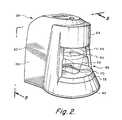
- FIG. 2is an isometric view of a preferred reader device in accordance with the present invention.
- FIG. 3is an isometric view of a preferred cup and cap
- FIG. 4is a plan view of the cap top surface
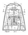
- FIG. 5is a front sectional view taken substantially along plane 5 - 5 of FIG. 2 ;
- FIG. 6is a top sectional view taken substantially along plane 6 - 6 of FIG. 5 ;
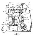
- FIG. 7is a side sectional view taken substantially along plane 7 - 7 of FIG. 5 showing the piston in its non-actuated position;
- FIG. 8is a side sectional view similar to FIG. 7 showing the piston in its actuated depressed position to force an aliquot to the cap for wetting the test strips;
- FIG. 9Ais a sectional view taken substantially along the plane 9 A- 9 A of FIG. 5 primarily showing the cup interior;
- FIG. 9Bis an enlarged sectional view showing the aliquot delivery mechanism of FIG. 9A in greater detail
- FIG. 10Ais a diagrammatic view of a typical test strip used in embodiments of the present invention.
- FIG. 10Bis a diagrammatic view of the test strip similar to FIG. 10A but modified to represent rectangular regions used to locate reference and drug lines;
- FIGS. 10C and 10Ddepict steps employed in analyzing a cap image to locate a strip reference line
- FIGS. 10E and 10Fdepict steps employed in analyzing a cap image to locate the presence of a strip drug line.
- FIG. 1depicts a preferred system 20 in accordance with the invention comprised of multiple service sites 22 respectively identified as 1 through N.
- Each service sitecan operate independently as a stand-alone system to perform a screening test, as will be described hereinafter.
- the multiple service sitesare connected to a network 24 , e.g., the Internet, for communication with a host computer 26 .
- Each service siteincludes a reader device 28 configured to cooperate with an assaying device 30 comprised of a specimen collection cup 32 and a cap 34 .
- FIG. 1depicts a functional block diagram of the reader 28 whereas FIGS. 2 and 4 - 7 illustrate the reader's structural configuration. The structural configuration of the assaying device 30 is illustrated in FIGS. 2-9 .
- the reader 28is comprised of a processor/controller 36 programmed to operate (1) a camera 37 and light source 38 via a camera interface circuit 40 and (2) a piston motor 42 via a motor control circuit 44 .
- the piston motor 42operates to deliver an aliquot from a specimen in the cup 32 to one or more test strips in the cap 34 .
- the test stripseach produce a visible reaction in response to being wetted by the aliquot.
- the camera 37 and light source 38operate together to capture an image of the test strip(s) enabling the processor/controller 36 to process the image to determine test validity and whether the specimen is free of chemical components being monitored.
- the reader 28preferably operates in conjunction with an input/output device 46 which enables a site attendant to enter information, e.g., donor identification information, via a device such as a touch pad or keyboard, and to view information, e.g. via an LCD display, provided by the processor/controller 36 .
- informatione.g., donor identification information
- a devicesuch as a touch pad or keyboard
- view informatione.g. via an LCD display
- the processor/controller 36is also preferably connected to the network 24 via a suitable connectivity device 48 , e.g., a modem. This enables the reader to upload data, e.g., test results, billing information, etc. to the host computer 26 . It also allows the host computer to exercise supervisory control over the processor/controller 36 .
- a suitable connectivity device 48e.g., a modem. This enables the reader to upload data, e.g., test results, billing information, etc. to the host computer 26 . It also allows the host computer to exercise supervisory control over the processor/controller 36 .
- FIG. 2illustrates the exterior configuration of the reader housing 60 .
- the housingis essentially comprised of a base portion 62 , a head portion 64 , and an enclosure portion 66 , bridging the base and head portions.
- a receptacle 68is defined between the base and head portions for receiving an assaying device 30 above a keyed recess 70 formed on base platform 72 .
- the keyed recess 70is shaped complementary to the lower periphery of the assaying device 30 to place the device in a specific orientation relative to head portion 64 .
- the assaying device 30is comprised of an open collection cup 32 and a detachable cap 34 .
- the cup 32defines an interior volume for collecting a fluid specimen, e.g. urine.
- each assaying device 30is intended to be used only once to collect a single specimen, it is preferably fabricated via relatively low cost plastic molding processes.
- the cup 32has an irregular lower periphery 76 particularly configured to mate with the keyed recess 70 .
- the periphery 76includes an enlarged front portion 78 and a reduced rear portion 80 .
- the reduced rear portion 80is bounded by flat finger grip sides 82 having raised surface features 84 extending to an oblique wall surface 86 .
- This irregular configuration of the cupfacilitates easy manual handling of the cup enabling it to be readily grasped by the hand of a user and/or administrator.
- the cup enlarged portion 78preferably includes an area 88 characterized by multiple vertical fins 90 . This area 88 functions as a key or registration area to which an index area 92 on the cap 34 is aligned to assure proper cap/cup sealing. Markings are preferably provided on the cup exterior to indicate maximum and minimum fill levels.
- the cap 34is comprised of a substantially circular member 94 having a top exterior surface 96 and a depending flange or skirt 98 .
- the skirt 98has a primarily knurled outer surface 100 that preferably defines flat areas 102 and the aforementioned index area 92 .
- the index area 92which may be defined by vertical slots, is preferably used to align with the aforementioned cup area 88 to visually indicate to a user that the cap has been properly installed onto the cup.
- the cap 34is preferably installed onto the cup via a mating thread 104 .
- the cap 34preferably carries a stop tooth 107 which rotates into engagement with the end fin 90 when the cap is properly installed onto the cup. When properly installed, the cap index area 92 will be aligned with the cup registration area 88 .
- Alternative mounting mechanismse.g., bayonet mount, can be used to couple the cap 34 to the cup 32 .
- the label 106preferably also includes a perforated tear-off third portion 113 which can be affixed to a “B” container in case of split specimen collections, or in the event that a manual chain of custody record is required.
- the cap top surface 96( FIG. 4 ) is either transparent or at least defines one or more transparent areas 114 , e.g., windows 114 A, 114 B, and 114 C for enabling a test strip mounted beneath each window to be visible therethrough.
- the capdefines one or more compartments each of which accommodates a test strip 115 which, when wetted by a fluid specimen, reacts to provide a visual indication indicative of a characteristic of the specimen.
- the window 114 Ccovers a test strip intended to detect specimen (1) authenticity and (2) adulteration.
- a freshly voided urine specimencan be authenticated by a test strip which senses various characteristics including temperature and/or creatinine content of the specimen.
- Adulteration of the specimencan be detected by a test strip sensitive to exogenous components, e.g. pH and/or nitrites.
- the test stripchanges color when wetted and detection is achieved using a colormetric technique Larger windows 114 A and 114 B are intended to reveal test strips 115 for detecting various specific chemical components typically associated with illegal substance abuse.
- FIG. 10Aschematically represents such a component test strip 116 showing multiple latent lines 117 visually represented on an indicator portion 118 extending from an absorbent portion 119 .
- the latent lines 117typically include one or more reference or control lines 117 R and multiple drug lines 117 D 1 , 117 D 2 , etc., each for a different drug or chemical component to be detected. If all of the lines visually appear within a certain test interval, e.g., up to eight minutes, after the absorbent portion 119 has been wetted, this will indicate the absence of the specific chemical components sought (i.e., a “negative” test). However, if any one of those specific chemical components is present in concentration above a certain threshold, its presence will suppress the appearance of one or more of the lines to indicate to an astute observer and/or computer based reader, the presence of that component.
- the cap top surface 96( FIG. 4 ) preferably additionally defines a primary bar code area 120 , a secondary bar code area 121 , and one or more fiducial marks 122 , to be discussed hereinafter. All of the windows 114 , bar code areas, and fiducial marks are arranged around a plunger hole 124 within a tightly dimensioned image field 125 suitable for being imaged onto the focal plane of camera 37 .
- the image fieldhas width and height dimensions respectively equal to 1446 mils and 1084 mils which is imaged onto a camera view field having 640 pixels horizontally and 480 pixels vertically.
- the assaying device cap 34defines descending concentric outer and inner tubular walls 126 and 127 .
- Multiple passageways 128 A, 128 B, 128 C, 128 Dextend vertically between the outer and inner tubular walls 126 and 127 .
- Each passageway 128defines a passageway inlet 129 at the lower end of inner tubular wall 127 and a passageway outlet 130 proximate to compartments 131 , respectively accommodating component or adulteration test strips 132 , located beneath the aforementioned windows 114 .
- Overflow Basins 136 , 138are respectively located adjacent to the compartments beneath windows 114 A, 114 B to collect any fluid overflow.
- the inner floor 150 of the cup 32is configured to define an open well 152 .
- the lower end of the outer tubular wall 126extends into the well 152 and essentially forms a closed chamber 154 for isolating a portion of the fluid specimen.
- a plunger 160comprised of a plunger pin 162 and plunger element 164 , is mounted in inner tubular wall 127 above chamber 154 .
- the plunger element 164is formed of soft conforming material able to seal against the inner surface of inner tubular wall 127 .
- the opening 124 in the cap top surface 96provides access to enable the pin 162 to be depressed.
- each aliquotcomprises a specific volume of fluid.
- FIGS. 5-8illustrate the internal structure of the reader housing 60 .
- the housing 60is formed by a base plate 150 having a vertical frame member 152 secured thereto.
- the base plate 151is weighted by block 154 for stability.
- a shell 160is affixed to the base plate 150 and frame member 152 .
- the shellincludes a base platform member 72 which defines the aforementioned keyed recess 70 .
- the shell 160additionally includes a rear shell member 162 which encloses a rear compartment 164 housing the reader electronic circuit board(s) 166 .
- An upper shell member 170encloses a top compartment 172 which houses the camera 37 , light source 38 and piston motor 42 .
- These devicesare structurally supported on arm 176 projecting forwardly from frame member 152 .
- a piston subassembly 180is mounted for vertical reciprocal motion toward and away from base plate 150 .
- the piston subassemblyis comprised of a support arm 182 projecting forwardly from slide block 184 mounted for linear movement along guide rails 186 .
- the support arm 182carries a piston member 186 aligned with opening 124 in the cap of an assaying device 30 placed in the keyed recess 70 .
- a lead screw 188is threaded into hole 190 in support arm 182 . The lead screw can be selectively rotated either clockwise or counterclockwise by piston motor 42 to move the slide block 184 either up or down.
- FIG. 7depicts the piston member 186 in its up position providing sufficient clearance to allow an assaying device 30 to be placed on or removed from the keyed recess 70 .
- FIG. 8shows the piston member 186 in its down position extending into cap opening 124 to depress plunger 160 to displace fluid from the specimen in cup 32 to wet the test strips 115 .
- the piston subassembly 180includes a substantially cylindrical light shield 192 mounted on slide block 184 .
- the light shield 192defines a lower edge 194 which seals against the cap top surface 96 when the slide block is in its down position shown in FIG. 8 .
- the camera 37can comprise a commercially available digital camera and appropriate optics for imaging the field 125 ( FIG. 4 ) onto the camera's focal plane.
- the camerapreferably has a resolution of 640 (horizontal).times.480 (vertical) pixels. Imaging is enhanced by selective illumination of light sources 38 and by the shielding effect afforded by light shield 192 .
- a preferred operational sequence for automatically testing a fluid specimenis represented by the following sequential steps:
- the site administratorfirst enters donor and client (e.g., employer) information via I/O devices 46 into a database stored either in processor 36 or host computer 26 .
- the donorvoids into a cup 32 and the cap 34 is sealed thereon.
- the labelis extended from the cap to the cup to assure that it is sealed in tamper evident fashion.
- the administrator and donorthen initial the sealed label and review the chain of custody document.
- the donor and administratorboth apply their signatures to the signature pad and a copy of the chain of custody document is printed and given to the donor. The donor is then dismissed.
- the cup/capis then placed in the reader.
- Step 4 of the foregoing sequenceis automatically executed under the control of programmed microprocessor 36 .
- the pistonhas not yet been inserted into the cup and may partially obscure the field of view.
- the light shieldis only partially effective, and extraneous light may enter, further obscuring details. Nevertheless, an initial image is captured by the camera to examine the primary barcode 120 and other cap features to determine if it is valid. If the barcode is not valid, this fact is displayed to the site administrator for further action. An invalid barcode can indicate that the cup is inserted incorrectly, that there is no cup there at all, or that a “fake” cup has been inserted. If the administrator cannot resolve the issue and the barcode is indeed invalid, testing is aborted and the sealed cup is sent for laboratory analysis.
- step 4bprocessor 36 runs the piston motor 42 to lower the piston 164 a predetermined distance. This also lowers the light shield 192 into place against the cap top surface 96 so that the light source 38 is then the only source of light illuminating the cap top.
- the light source 38preferably comprises multiple green LED's inasmuch as the lines that appear on typical component test strips exhibit the highest contrast when viewed in green light. With the piston in its down position, it no longer obscures any cap features within the image field 125 .
- step 4canother image of the cap is captured and processed to double-check the primary barcode results from the previous step and to read the secondary barcode 121 and the fiducial marks 122 .
- the fiducial marks 122are small features printed on the cap directly above the test strip windows 114 A, 114 B and serve as reference points for subsequent processing steps to assure accurate image analysis.
- the barcode labelshave their own fiducial marks, which allow the barcodes to be found and read even if the label is askew. If all barcodes and fiducial marks can be located and properly read, then operation proceeds to step 4d. Otherwise, the site administrator is alerted and he/she decides whether to proceed or not.
- step 4dimages are periodically captured and during step 4e, the images are processed and analyzed. Steps 4d and 4e are executed in an iterative loop. If all latent lines become visible after two minutes, the test is concluded and operation proceeds to step 4f. Otherwise steps 4d and 4e are executed every minute until eight minutes have elapsed. If any of the drug or control lines do not become visible, the assaying device is sent to the lab for further analysis.
- the image analysis executed in step 4eincludes an extensive procedure to be discussed hereinafter for discerning a color change on the adulteration test strip and visible reference and drug lines on the component test strip.
- the detection of these linescan be reasonably challenging because the amplitude, i.e., dark or light, of its pixels can vary widely dependent on several factors including variations in test strips, in wetting, in urine color, etc.
- a sequencee.g., 8
- These multiple imagesare then mathematically summed divided by the number of images in order to produce an integrated image in which the random electrical and optical “noise” has been reduced by this “averaging” process. This integrated image is then used in the subsequent line detection procedure:
- a final test resultfor adulteration and identification of drug lines present and/or absent, is locally displayed and/or communicated to the host computer in accordance with aforementioned step 4f.
- the foregoingdescribes applicants' preferred system for automatically testing fluid specimens to detect specific chemical components therein.
- the preferred systemincludes an assaying device comprised of a fluid collection cup and a cap carrying one or more test strips configured to produce visually discernable indications of the components of the specimen and/or specimen adulteration.
- the visual indicationsare read by an imager, e.g., digital camera, and interpreted by a processor which executes an analysis procedure to interpret the visual indications.
- the resulting test resultsare reported locally or via a communications network to a host computer.
- systems in accordance with the inventioncan quickly (e.g., in less than 15 minutes) and locally automatically test a fluid specimen to provide accurate qualitative test results.
- the systemboth assures the confidentiality of donor/specimen test results (by using machine readable, rather than human readable, markings) and a closely controlled chain of custody procedure.
Landscapes
- Health & Medical Sciences (AREA)
- Engineering & Computer Science (AREA)
- Chemical & Material Sciences (AREA)
- Life Sciences & Earth Sciences (AREA)
- Immunology (AREA)
- Hematology (AREA)
- General Health & Medical Sciences (AREA)
- Molecular Biology (AREA)
- Analytical Chemistry (AREA)
- Physics & Mathematics (AREA)
- General Physics & Mathematics (AREA)
- Urology & Nephrology (AREA)
- Biomedical Technology (AREA)
- Biochemistry (AREA)
- Pathology (AREA)
- Business, Economics & Management (AREA)
- Microbiology (AREA)
- Cell Biology (AREA)
- Food Science & Technology (AREA)
- Medicinal Chemistry (AREA)
- Biotechnology (AREA)
- Clinical Laboratory Science (AREA)
- Chemical Kinetics & Catalysis (AREA)
- Theoretical Computer Science (AREA)
- Primary Health Care (AREA)
- Public Health (AREA)
- Medical Informatics (AREA)
- Epidemiology (AREA)
- Marketing (AREA)
- General Business, Economics & Management (AREA)
- Strategic Management (AREA)
- Economics (AREA)
- Accounting & Taxation (AREA)
- Finance (AREA)
- Development Economics (AREA)
- Entrepreneurship & Innovation (AREA)
- Bioinformatics & Cheminformatics (AREA)
- Pharmacology & Pharmacy (AREA)
- Dispersion Chemistry (AREA)
- Human Computer Interaction (AREA)
Abstract
Description
- 1. Fluid deposited into cup at local site; secure cap in tamper evident fashion;
- 2. Site administrator places assaying device, i.e., cup and cap, into “keyed” receptacle of local reader and enters ID information;
- 3. Reader alerts host computer via communication network;
- 4. Initiate automatic reader operational sequence:
- a. capture cap image and verify acceptability to proceed
- b. run piston motor to advance piston into assaying device to force fluid up channels to wet component and adulteration test strips
- c. capture cap image and verify acceptability to proceed
- d. periodically capture additional cap images during development interval up to about eight minutes
- e. analyze captured image data to determine
- 1. test validity
- 2. test results
- f. locally display test validity/results and/or communicate test validity/results to Host computer
- g. run piston motor to withdraw piston from cup
- 5. Site administrator removes cup from reader
- 1. Donor at a local site deposits fluid into
cup 32; site administrator enters identification information and securescap 34 in tamper evident fashion; - 2. Administrator places cup/cap into “keyed”
receptacle 70 oflocal reader 28 and enters ID information; - 3.
Reader 28alerts host computer 26 viacommunication network 24; - 4. Host computer26 (or administrator) initiates reader operational sequence:
- a.
camera 37 captures cap image andprocessor 36 verifies acceptability to proceed - b.
processor 36runs piston motor 42 to advancepiston 164 into cup to force fluid up channels128 to wet component and adulteration test strips - c. camera captures additional cap image and verify acceptability to proceed
- d. periodically capture additional cap images during development interval up to about eight minutes
- e. processor analyzes captured image data to determine
- 1. test validity
- 2. test results
f. processor 36 displays test validity/results on local I/O 46 and/or communicates test validity/results toHost computer 26- g.
processor 36 runs piston motor to withdraw piston from cup
- a.
- 5. Site administrator removes cup from reader
- 1. Donor at a local site deposits fluid into
- 4e(1) The fiducial marks122, which had been found to exist in step 4c, are now located precisely by looking in a restricted region (as a consequence of the cup being physically positioned by keyed recess70) and finding the centroid of the individual fiducial marks. This determines their exact locations within the camera field of view (i.e., 640×480).
- 4e(2) Based on the locations of the fiducial marks, the image is now rotated, translated, minified, and or magnified as necessary so that the resulting image has the fiducial marks122 (and hence all other cap features) in “standard” positions which is hence presumed for all subsequent operations.
- 4e(3) Using a “map” of the features present on the cap top, each test is individually examined. Although the two test strips can in fact differ in the number of lines present and their specific locations, for the sake of simplicity, the operations on only one typical test strip will be described.
- 4e(4) Based on known default reference and drug line positions, non-overlapping
rectangular regions 200 are “drawn” around each reference line117R and drug line, e.g.,117D (FIG. 10B ). - 4e(5) For the
region 200 which contains the reference line117R, row sums are produced. The number of pixels summed for each row is the “width” of the test strip (e.g.,32 inFIG. 10C ), the number of total row sums for each region is the “height” of the individual region (e.g.,48 inFIG. 10C ). Each of these row sums produces a graph (FIG. 10D ) whose X axis is related to the “height” of the region, and whose Y axis is related to the values of individual row sums. Let it be assumed that individual row sums will be smaller for darker horizontal rows and larger for lighter horizontal rows. The resulting graphs are then preferably normalized so that the Y axis values are between 0 and 100, and then subtracted from 100 so that the darkest row in a given region has thevalue 100 and the brightest row in a given region has the value 0. Bell shaped curves will result (presuming a drug or control line is present) as depicted inFIG. 10D . - 4e(6) The reference line117R must be located in order to proceed further and its exact position must be determined in order to locate the best estimated positions of the drug lines for further processing. The graph for the reference line is examined for a maximum value, which represents the reference line center position. After the center position is located, the regions drawn in substep 4e(4) above are redrawn to center the reference line and drug lines in their respective regions.
- 4e(7) For each drug region, row sums and the resulting graph are produced as described in substep 4e(5) above.
- 4e(8) Each drug region graph is divided into three equal parts, a left, center, and right part as represented in
FIG. 10F . The drug line is presumed to occupy the center portion. However, its exact position and width can vary, and its brightness difference in relation to the neighboring area may be very subtle. Based on different wetting conditions, a dark condition in one region can in fact be lighter than a not-dark condition in another region. Hence, a relative mechanism is used to determine the presence or absence of a drug line. - 4e(9) For each drug region graph, the total area under each of the three regions (left, center, right) is calculated. The left and right region areas are then numerically summed, and this resulting total area sum is multiplied by an experimentally determined “weighting value”, thus producing a weighted sum. If the area of the center region is greater than this weighted sum, a decision is made that a line is present. If the area of the center region is less than or equal to the weighted sum, a decision is made that no line is present. By using urine samples with known drug concentrations, a weighting value of 0.75 has been found to produce very acceptable results. In order to conceptually understand what is going on, presume that the graph is perfectly symmetric and the drug line is centered in the graph, hence the graph will appear as a bell curve (
FIG. 10F ) (this is typical of the actual graphs produced) if a line is present, or at the other extreme, will appear as a flat line if no drug line is present. In the case of a flat line, then the summed areas of the left and right region will be exactly twice (2*X) the area of the center region (X). If the 2*X value is weighted by 0.75, the resulting area is now 1.5*X, which is greater than X. Hence no drug line is considered present. In fact, the weighting value would have to be less than 0.5 for a line to be considered present. As the center region grows in amplitude, its area reaches a point that it is now greater than the weighted sum of the left and right regions, and a line is considered present. Note that the presence or absence of a line is not determined by the exact position or shape of this curve, nor by the exact amplitudes of the dark and light components, which can vary widely based on various factors including the degree of wetting, the color of the urine, the particular lot of test strips, the time of exposure, extraneous material on the test strip, and shadows and/or reflections. All of these variations are compensated for in the relatively simple and concise mathematical procedure described which allows the presence or absence of drug lines to be repeatedly determined to a controllable, high degree of accuracy.
Claims (16)
Priority Applications (3)
| Application Number | Priority Date | Filing Date | Title |
|---|---|---|---|
| US13/479,125US8455257B2 (en) | 1999-02-05 | 2012-05-23 | System for automatically testing a fluid specimen |
| US13/908,833US9018015B2 (en) | 1999-02-05 | 2013-06-03 | Method of securing a chain of custody of a specimen of a donor |
| US14/695,384US20150227777A1 (en) | 1999-02-05 | 2015-04-24 | System for securing a chain of custody of a specimen of a donor |
Applications Claiming Priority (8)
| Application Number | Priority Date | Filing Date | Title |
|---|---|---|---|
| US09/245,175US6342183B1 (en) | 1997-02-14 | 1999-02-05 | System for collecting and locally analyzing a fluid specimen |
| US09/444,926US6514461B1 (en) | 1997-02-14 | 1999-11-24 | System for automatically testing a fluid specimen |
| US10/072,154US6716393B2 (en) | 1997-02-14 | 2002-02-06 | System for automatically testing a fluid specimen |
| US10/779,014US6964752B2 (en) | 1997-02-14 | 2004-02-13 | System for automatically testing a fluid specimen |
| US10/954,823US7537733B2 (en) | 1997-02-14 | 2004-09-30 | System for automatically testing a fluid specimen |
| US11/553,836US7943381B2 (en) | 1999-02-05 | 2006-10-27 | Method for testing specimens located at a plurality of service sites |
| US13/100,393US8202729B2 (en) | 1999-02-05 | 2011-05-04 | Method for automatically testing a fluid specimen |
| US13/479,125US8455257B2 (en) | 1999-02-05 | 2012-05-23 | System for automatically testing a fluid specimen |
Related Parent Applications (1)
| Application Number | Title | Priority Date | Filing Date |
|---|---|---|---|
| US13/100,393ContinuationUS8202729B2 (en) | 1999-02-05 | 2011-05-04 | Method for automatically testing a fluid specimen |
Related Child Applications (1)
| Application Number | Title | Priority Date | Filing Date |
|---|---|---|---|
| US13/908,833ContinuationUS9018015B2 (en) | 1999-02-05 | 2013-06-03 | Method of securing a chain of custody of a specimen of a donor |
Publications (2)
| Publication Number | Publication Date |
|---|---|
| US20120284054A1 US20120284054A1 (en) | 2012-11-08 |
| US8455257B2true US8455257B2 (en) | 2013-06-04 |
Family
ID=26937042
Family Applications (12)
| Application Number | Title | Priority Date | Filing Date |
|---|---|---|---|
| US09/444,926Expired - LifetimeUS6514461B1 (en) | 1997-02-14 | 1999-11-24 | System for automatically testing a fluid specimen |
| US10/072,154Expired - LifetimeUS6716393B2 (en) | 1997-02-14 | 2002-02-06 | System for automatically testing a fluid specimen |
| US10/779,014Expired - Fee RelatedUS6964752B2 (en) | 1997-02-14 | 2004-02-13 | System for automatically testing a fluid specimen |
| US10/954,823Expired - Fee RelatedUS7537733B2 (en) | 1997-02-14 | 2004-09-30 | System for automatically testing a fluid specimen |
| US11/063,408AbandonedUS20050214865A1 (en) | 1997-02-14 | 2005-02-23 | Changeable machine readable assaying indicia |
| US11/553,819AbandonedUS20070048875A1 (en) | 1999-02-05 | 2006-10-27 | Method and system for testing and controlling a custody of a fluid specimen |
| US11/553,836Expired - Fee RelatedUS7943381B2 (en) | 1999-02-05 | 2006-10-27 | Method for testing specimens located at a plurality of service sites |
| US11/845,229AbandonedUS20070298436A1 (en) | 1997-02-14 | 2007-08-27 | Changeable machine readable assaying indicia |
| US13/100,393Expired - Fee RelatedUS8202729B2 (en) | 1999-02-05 | 2011-05-04 | Method for automatically testing a fluid specimen |
| US13/479,125Expired - Fee RelatedUS8455257B2 (en) | 1999-02-05 | 2012-05-23 | System for automatically testing a fluid specimen |
| US13/908,833Expired - Fee RelatedUS9018015B2 (en) | 1999-02-05 | 2013-06-03 | Method of securing a chain of custody of a specimen of a donor |
| US14/695,384AbandonedUS20150227777A1 (en) | 1999-02-05 | 2015-04-24 | System for securing a chain of custody of a specimen of a donor |
Family Applications Before (9)
| Application Number | Title | Priority Date | Filing Date |
|---|---|---|---|
| US09/444,926Expired - LifetimeUS6514461B1 (en) | 1997-02-14 | 1999-11-24 | System for automatically testing a fluid specimen |
| US10/072,154Expired - LifetimeUS6716393B2 (en) | 1997-02-14 | 2002-02-06 | System for automatically testing a fluid specimen |
| US10/779,014Expired - Fee RelatedUS6964752B2 (en) | 1997-02-14 | 2004-02-13 | System for automatically testing a fluid specimen |
| US10/954,823Expired - Fee RelatedUS7537733B2 (en) | 1997-02-14 | 2004-09-30 | System for automatically testing a fluid specimen |
| US11/063,408AbandonedUS20050214865A1 (en) | 1997-02-14 | 2005-02-23 | Changeable machine readable assaying indicia |
| US11/553,819AbandonedUS20070048875A1 (en) | 1999-02-05 | 2006-10-27 | Method and system for testing and controlling a custody of a fluid specimen |
| US11/553,836Expired - Fee RelatedUS7943381B2 (en) | 1999-02-05 | 2006-10-27 | Method for testing specimens located at a plurality of service sites |
| US11/845,229AbandonedUS20070298436A1 (en) | 1997-02-14 | 2007-08-27 | Changeable machine readable assaying indicia |
| US13/100,393Expired - Fee RelatedUS8202729B2 (en) | 1999-02-05 | 2011-05-04 | Method for automatically testing a fluid specimen |
Family Applications After (2)
| Application Number | Title | Priority Date | Filing Date |
|---|---|---|---|
| US13/908,833Expired - Fee RelatedUS9018015B2 (en) | 1999-02-05 | 2013-06-03 | Method of securing a chain of custody of a specimen of a donor |
| US14/695,384AbandonedUS20150227777A1 (en) | 1999-02-05 | 2015-04-24 | System for securing a chain of custody of a specimen of a donor |
Country Status (5)
| Country | Link |
|---|---|
| US (12) | US6514461B1 (en) |
| EP (1) | EP1151294A1 (en) |
| JP (1) | JP2002536641A (en) |
| AU (1) | AU2752700A (en) |
| WO (1) | WO2000046598A1 (en) |
Cited By (3)
| Publication number | Priority date | Publication date | Assignee | Title |
|---|---|---|---|---|
| US20110293153A1 (en)* | 2008-11-14 | 2011-12-01 | Optricon Gmbh | Appliance and method for evaluation and assessment of a test strip |
| US20130268450A1 (en)* | 1999-02-05 | 2013-10-10 | Escreen, Inc. | Method of securing a chain of custody of a specimen of a donor |
| US10856792B2 (en) | 2018-02-22 | 2020-12-08 | Medtronic, Inc. | Urinary symptom management |
Families Citing this family (107)
| Publication number | Priority date | Publication date | Assignee | Title |
|---|---|---|---|---|
| US6342183B1 (en)* | 1997-02-14 | 2002-01-29 | Escreen | System for collecting and locally analyzing a fluid specimen |
| US7108662B2 (en) | 1999-04-21 | 2006-09-19 | Quest Diagnostics Incorporated | Device and method for sample collection |
| US6702988B1 (en)* | 1999-04-21 | 2004-03-09 | Peter J. Sagona | Automatic on-site drug testing system and method |
| US6998273B1 (en)* | 2000-02-09 | 2006-02-14 | A-Fem Medical Corporation | Collection device for lateral flow chromatography |
| AU8561501A (en)* | 2000-09-22 | 2002-04-02 | Cryosite Ltd | System and method for management of specimens |
| US6937323B2 (en)* | 2000-11-08 | 2005-08-30 | Burstein Technologies, Inc. | Interactive system for analyzing biological samples and processing related information and the use thereof |
| AU2002241602A1 (en)* | 2000-11-16 | 2002-06-11 | Burstein Technologies, Inc. | Methods and apparatus for detecting and quantifying lymphocytes with optical biodiscs |
| GB0110476D0 (en) | 2001-04-30 | 2001-06-20 | Secr Defence | Reagent delivery system |
| US6890484B2 (en) | 2001-05-18 | 2005-05-10 | Acon Laboratories, Inc. | In line test device and methods of use |
| US6565808B2 (en) | 2001-05-18 | 2003-05-20 | Acon Laboratories | Line test device and methods of use |
| US7300626B2 (en)* | 2001-05-21 | 2007-11-27 | John Wu | Fluid-specimen collecting and testing device and method for recording chromatographic assay test results |
| US20020198748A1 (en)* | 2001-05-25 | 2002-12-26 | Eden Thomas M. | System and method for implementing an employee-rights-sensitive drug free workplace policy |
| USD494279S1 (en) | 2001-07-25 | 2004-08-10 | Applied Biotech, Inc. | Urine test device |
| US6669908B2 (en)* | 2001-07-25 | 2003-12-30 | Applied Biotech, Inc. | Urine test device |
| US6680027B2 (en)* | 2001-07-30 | 2004-01-20 | Princeton Biomeditech Corporation | Fluid sample collection and isolation cup |
| AU2002327523A1 (en)* | 2001-08-24 | 2003-03-10 | American Bio Medica Corporation | Method of conducting and documenting analyte screening tests |
| US20030143637A1 (en)* | 2001-08-31 | 2003-07-31 | Selvan Gowri Pyapali | Capture layer assemblies for cellular assays including related optical analysis discs and methods |
| AU2002335715A1 (en)* | 2001-09-07 | 2003-03-24 | Burstein Technologies, Inc. | Optical bio-disc systems for nuclear morphology based identification |
| US20070179717A1 (en)* | 2001-09-21 | 2007-08-02 | Milliken Gordon L | System and method for management of specimens |
| WO2003044481A2 (en)* | 2001-11-20 | 2003-05-30 | Burstein Technologies, Inc. | Optical bio-discs and microfluidic devices for analysis of cells |
| AU2003291739A1 (en)* | 2002-11-19 | 2004-06-15 | Jin Po Lee | Method and system for analyzing test devices |
| TWI340829B (en) | 2002-12-27 | 2011-04-21 | Transpacific Systems Llc | Method for determining a response of each probe zone on a test strip |
| US7197169B2 (en)* | 2003-01-02 | 2007-03-27 | Kuo-Jeng Wang | Method for detecting a response of each probe zone on a test strip |
| US7097103B2 (en)* | 2003-05-22 | 2006-08-29 | Wen-Chao Tseng | Method of automatically detecting a test result of a probe zone of a test strip |
| FI116261B (en)* | 2003-11-06 | 2005-10-14 | Valtion Teknillinen | System and method and server for analyzing image data and reading device for determining code data |
| DE212004000062U1 (en)* | 2003-11-14 | 2006-07-20 | Oakville Trading Hong Kong Ltd. | Sample collector with integrated sample analysis system |
| US20070143035A1 (en)* | 2005-12-19 | 2007-06-21 | Petruno Patrick T | Diagnostic test reader with disabling unit |
| US7402423B2 (en)* | 2004-08-13 | 2008-07-22 | Biomed Solutions, Llc | Apparatus for the detection of pepsin |
| USD561904S1 (en)* | 2005-01-31 | 2008-02-12 | Home Diagnostics, Inc. | Meter for an integrated diagnostic test system |
| EP3026874B1 (en)* | 2005-04-01 | 2019-11-06 | Polymer Technology Systems, Inc. | Body fluid testing component for analyte detection |
| CN100478671C (en)* | 2005-10-25 | 2009-04-15 | 艾康生物技术(杭州)有限公司 | Detection device and method for liquid sample |
| US8491850B2 (en)* | 2005-12-19 | 2013-07-23 | Alverix, Inc. | Diagnostic test reader with locking mechanism |
| US7652268B2 (en) | 2006-01-31 | 2010-01-26 | Jp Laboratories, Inc | General purpose, high accuracy dosimeter reader |
| US8940246B2 (en) | 2006-03-13 | 2015-01-27 | Nipro Diagnostics, Inc. | Method and apparatus for coding diagnostic meters |
| US11559810B2 (en) | 2006-03-13 | 2023-01-24 | Trividia Health, Inc. | Method and apparatus for coding diagnostic meters |
| WO2007149928A2 (en)* | 2006-06-20 | 2007-12-27 | Choicepoint Asset Company | Electronic chain of custody systems & methods for use with drug testing |
| KR20080009396A (en)* | 2006-07-24 | 2008-01-29 | 주식회사 큐리어스 | Urine analysis instrument |
| US8491851B2 (en)* | 2006-08-25 | 2013-07-23 | Alverix, Inc. | System and method for enabling and disabling a portable assay reader device |
| WO2008090551A2 (en)* | 2007-01-23 | 2008-07-31 | Association For Public Health Services | Liquid testing assembly |
| JP4528336B2 (en)* | 2007-03-10 | 2010-08-18 | ローム アンド ハース カンパニー | How to read a test strip |
| US8150115B2 (en)* | 2007-04-18 | 2012-04-03 | Iris International, Inc. | Chemistry strip reader and method |
| US20080267446A1 (en)* | 2007-04-18 | 2008-10-30 | Dale Capewell | Chemistry strip reader and method |
| CN101382510B (en)* | 2007-09-06 | 2012-07-25 | 清华大学 | Multi-bottle test container |
| US20100239137A1 (en)* | 2007-10-09 | 2010-09-23 | Siemens Healthcare Diagnostics Inc. | Two Dimensional Imaging of Reacted Areas On a Reagent |
| US8005280B2 (en)* | 2007-12-12 | 2011-08-23 | Jadak, Llc | Optical imaging clinical sampler |
| AU2008343568B2 (en) | 2007-12-27 | 2015-05-14 | Siemens Heathcare Diagnostics Inc. | Method and apparatus for remote multiple-process graphical monitoring |
| USD600811S1 (en)* | 2008-01-22 | 2009-09-22 | Home Diagnostics, Inc. | Diagnostic test system |
| US20090199606A1 (en)* | 2008-02-07 | 2009-08-13 | Yoram Gil | Tamper evident seal |
| US8446463B2 (en) | 2008-08-22 | 2013-05-21 | Genprime, Inc. | Apparatus, method and article to perform assays using assay strips |
| CN105740641A (en) | 2009-10-19 | 2016-07-06 | 提拉诺斯公司 | Integrated health data capture and analysis system |
| CN103969427B (en)* | 2009-11-23 | 2016-03-16 | 艾博生物医药(杭州)有限公司 | A kind of device detecting analyte in sample |
| AU2013204428B2 (en)* | 2010-01-28 | 2016-03-31 | Ellume Pty Ltd | Sampling and testing device for the human or animal body |
| CN102859358B (en)* | 2010-01-28 | 2015-05-13 | 埃吕梅有限公司 | Sampling and testing device for the human or animal body |
| US20110213564A1 (en)* | 2010-02-26 | 2011-09-01 | Henke Tom L | Method and apparatus for code verified testing |
| ITMI20101051A1 (en)* | 2010-06-10 | 2011-12-11 | Silmarc Pharma Srl | DEVICE FOR ANALYSIS AND PRINTING OF RAPID TEST RESULTS ON BIOLOGICAL FLUIDS |
| CA2805486C (en)* | 2010-07-20 | 2018-03-06 | Becton, Dickinson And Company | Method for linking point of care rapid diagnostic testing results to laboratory-based methods |
| US8655009B2 (en) | 2010-09-15 | 2014-02-18 | Stephen L. Chen | Method and apparatus for performing color-based reaction testing of biological materials |
| US8506901B2 (en) | 2010-11-03 | 2013-08-13 | Teco Diagnostics | All-in-one specimen cup with optically readable results |
| JP6090835B2 (en) | 2010-12-20 | 2017-03-08 | Necソリューションイノベータ株式会社 | Detection tool and detection system |
| CN105181946B (en)* | 2011-04-29 | 2018-04-06 | 艾博生物医药(杭州)有限公司 | The device of analyte in a kind of detection sample prompted by sending sound |
| CN102323215A (en)* | 2011-08-05 | 2012-01-18 | 广州万孚生物技术有限公司 | Analyzing and reading device and method |
| US9352312B2 (en) | 2011-09-23 | 2016-05-31 | Alere Switzerland Gmbh | System and apparatus for reactions |
| USD679410S1 (en) | 2012-02-03 | 2013-04-02 | Respirio Pty Ltd | Sampling and testing device |
| JP5900002B2 (en)* | 2012-02-17 | 2016-04-06 | 株式会社島津製作所 | Analysis device control system and program |
| DE102012205171B3 (en)* | 2012-03-29 | 2013-09-12 | Fraunhofer-Gesellschaft zur Förderung der angewandten Forschung e.V. | Integrated disposable chip cartridge system for mobile multi-parameter analysis of chemical and / or biological substances |
| US20130280698A1 (en)* | 2012-04-24 | 2013-10-24 | Arizona Board Of Regents, Acting For And On Behalf Of Northern Arizona University | Rapid multiplex lateral flow assay device |
| GB201212887D0 (en)* | 2012-07-19 | 2012-09-05 | Berger Blackwell Devices Ltd | Apparatus for testing a liquid specimen |
| EP2883037B1 (en) | 2012-08-08 | 2023-06-07 | Healthy.io Ltd. | Method and apparatus for performing and quantifying color changes induced by specific concentrations of biological analytes in an automatically calibrated environment |
| US9285323B2 (en) | 2012-08-08 | 2016-03-15 | Scanadu Incorporated | Quantifying color changes of chemical test pads induced concentrations of biological analytes under different lighting conditions |
| US9528941B2 (en) | 2012-08-08 | 2016-12-27 | Scanadu Incorporated | Method and apparatus for determining analyte concentration by quantifying and interpreting color information captured in a continuous or periodic manner |
| US10890590B2 (en) | 2012-09-27 | 2021-01-12 | Ellume Limited | Diagnostic devices and methods |
| CN105050720A (en) | 2013-01-22 | 2015-11-11 | 华盛顿大学商业化中心 | Sequential delivery of fluid volumes and associated devices, systems and methods |
| US20160188937A1 (en)* | 2013-07-30 | 2016-06-30 | Express Diagnostics Int'l., Inc. | Universal assay reader |
| US10376880B2 (en) | 2013-07-30 | 2019-08-13 | Carehealth America Corporation | Lateral flow devices and methods of manufacture and use |
| DE102013017148B4 (en)* | 2013-10-16 | 2015-08-06 | Heiko Langer | Liquid analysis method and analysis kit |
| US20150160245A1 (en)* | 2013-11-05 | 2015-06-11 | Marya Lieberman | Ppm quantification of iodate using paper device |
| ES2964604T3 (en)* | 2014-07-07 | 2024-04-08 | Attenti Electronic Monitoring Ltd | Tamper-proof self-administered drug screening |
| WO2016010959A1 (en)* | 2014-07-14 | 2016-01-21 | Centero Llc | System and apparatus for a wireless fluid analyzer |
| WO2016025935A2 (en) | 2014-08-15 | 2016-02-18 | Scanadu Incorporated | Precision luxmeter methods for digital cameras to quantify colors in uncontrolled lighting environments |
| US10786229B2 (en) | 2015-01-22 | 2020-09-29 | Ellume Limited | Diagnostic devices and methods for mitigating hook effect and use thereof |
| WO2017053680A1 (en)* | 2015-09-25 | 2017-03-30 | Alere Inc. | Biometric confirmation of sample integrity |
| US10386376B2 (en) | 2015-11-09 | 2019-08-20 | Jeimei, Llc | Sample container with integrated test strip |
| RU2753491C2 (en)* | 2015-11-09 | 2021-08-17 | Новамед Лтд. | Device for collecting and diagnosing body fluids |
| USD810084S1 (en)* | 2016-03-23 | 2018-02-13 | Formfox, Inc. | Mobile scanner |
| CN105738358B (en)* | 2016-04-01 | 2018-11-16 | 杭州赛凯生物技术有限公司 | Illicit drugs inspection system |
| US11386552B2 (en) | 2016-08-01 | 2022-07-12 | Genprime, Inc. | System and method to interpret tests that change color to indicate the presence or non-presence of a compound |
| US10514339B2 (en)* | 2016-08-30 | 2019-12-24 | Htc Corporation | Test strip analyser having frame with movable support and test strip carrier |
| US10576475B2 (en) | 2016-09-15 | 2020-03-03 | Genprime, Inc. | Diagnostic assay strip cassette |
| CN106454028A (en)* | 2016-09-29 | 2017-02-22 | 北京倍肯创新诊断技术研究院有限责任公司 | Image acquisition unit of dry type detection analyzer |
| AU2017384972B2 (en)* | 2016-12-28 | 2020-02-27 | Neogen Corporation | Fluid retainer cartridge assembly and method for utilizing the same |
| EP3351304A1 (en) | 2017-01-24 | 2018-07-25 | Thomas Meseg | Test cup for analysing a fluid specimen, device for analysing a fluid specimen,kit of parts, and method |
| US10966690B2 (en)* | 2017-03-28 | 2021-04-06 | Marc Kopoian | Specimen container system |
| WO2018194525A1 (en) | 2017-04-18 | 2018-10-25 | Yeditepe Universitesi | Biochemical analyser based on a machine learning algorithm using test strips and a smartdevice |
| WO2019193438A1 (en)* | 2018-04-03 | 2019-10-10 | Ashish Anand | Automated detection of tampering |
| CN110389057B (en)* | 2018-04-23 | 2024-12-31 | 上海伯顿医疗设备有限公司 | Integrated multifunctional biological sample processor |
| CN112543677B (en)* | 2018-09-21 | 2023-05-05 | 福斯分析仪器公司 | Sampling device, system comprising same and method |
| EP3980182A1 (en)* | 2019-06-04 | 2022-04-13 | Abbott Toxicology Limited | Fluid specimen testing |
| CN110728198B (en)* | 2019-09-20 | 2021-02-19 | 北京三快在线科技有限公司 | Image processing method and device, electronic equipment and readable storage medium |
| IT201900020152A1 (en)* | 2019-10-31 | 2021-05-01 | Euro F I S R L | DIAGNOSTIC DEVICE FOR TOXICOLOGICAL ANALYSIS OF URINE EQUIPPED WITH MULTIPLE TANK |
| CA3160797A1 (en) | 2019-11-13 | 2021-05-20 | Scanwell Health, Inc. | Diagnostic test kits for sample preparation and analysis |
| US20220020481A1 (en) | 2020-07-20 | 2022-01-20 | Abbott Laboratories | Digital pass verification systems and methods |
| WO2022060415A1 (en) | 2020-09-17 | 2022-03-24 | Scanwell Health, Inc. | Diagnostic test kits and methods of analyzing the same |
| USD970033S1 (en) | 2020-10-23 | 2022-11-15 | Becton, Dickinson And Company | Cartridge imaging background device |
| US11988596B2 (en) | 2020-10-23 | 2024-05-21 | Becton, Dickinson And Company | Systems and methods for imaging and image-based analysis of test devices |
| US11860103B2 (en) | 2020-10-26 | 2024-01-02 | K2R2 | Sample identification |
| US20220134329A1 (en)* | 2020-11-05 | 2022-05-05 | Analog Devices, Inc. | Internal positive control for diagnostic assays |
| RU203230U1 (en)* | 2020-12-26 | 2021-03-29 | Общество с ограниченной ответственностью "Гранат Био Тех" (ООО "Гранат Био Тех") | Device for sampling and research of biomaterial |
Citations (1)
| Publication number | Priority date | Publication date | Assignee | Title |
|---|---|---|---|---|
| US6149440A (en)* | 1998-09-18 | 2000-11-21 | Wyngate, Inc. | Methods and apparatus for authenticating informed consent |
Family Cites Families (96)
| Publication number | Priority date | Publication date | Assignee | Title |
|---|---|---|---|---|
| US3832134A (en) | 1971-10-04 | 1974-08-27 | D Sohn | Tlc method and device for detecting the presence of target substances in unknown solutions |
| SE360179B (en) | 1972-01-31 | 1973-09-17 | F Linder | |
| IT949871B (en)* | 1972-03-03 | 1973-06-11 | Fontana A | PRESS FOR EXPOSURE AND PHOTOINCI SION IN PARTICULAR FOR CIRCUITS PRINTED ON SINGLE AND DOUBLE SIDES |
| US4042329A (en) | 1974-12-18 | 1977-08-16 | Becton, Dickinson And Company | Method and device for detecting cholesterol |
| US3980436A (en) | 1974-12-19 | 1976-09-14 | Sci-Med Laboratories, Inc. | Analytic test device |
| US4059407A (en) | 1976-04-14 | 1977-11-22 | Becton, Dickinson And Company | Disposable chemical indicators |
| US4070249A (en) | 1976-06-08 | 1978-01-24 | American Home Products Corporation | Apparatus for compensating for pressure within a biological test device |
| US4040791A (en) | 1976-06-22 | 1977-08-09 | David H Kuntz | Specimen collecting device |
| US4473530A (en) | 1980-09-24 | 1984-09-25 | Villa Real Antony Euclid C | Compact sanitary urinalysis unit |
| US4385115A (en) | 1980-10-22 | 1983-05-24 | Hoffmann-La Roche Inc. | Diagnostics testing devices and processes |
| US4454235A (en) | 1982-06-01 | 1984-06-12 | Miles Laboratories, Inc. | Capillary tube holder for liquid transfer in immunoassay |
| US4557274A (en) | 1982-06-07 | 1985-12-10 | Cawood Charles David | Midstream urine collector |
| US4435504A (en) | 1982-07-15 | 1984-03-06 | Syva Company | Immunochromatographic assay with support having bound "MIP" and second enzyme |
| US4458020A (en) | 1982-11-15 | 1984-07-03 | Quidel | Integrated single tube plunger immunoassay system having plural reagent chambers |
| US4992296A (en) | 1987-05-26 | 1991-02-12 | Gibson Jacob J | Abuse-type drug test papers and methods of making and using same |
| US4573983A (en) | 1984-07-27 | 1986-03-04 | The Kendall Company | Liquid collection system having an anti-septic member on the discharge section |
| US4844866A (en) | 1984-11-13 | 1989-07-04 | Matrix Technologies, Inc. | Carrier for detecting drug abuse compounds |
| US4624929A (en) | 1984-12-03 | 1986-11-25 | Syntex (U.S.A.) Inc. | Sample collector and assay device and method for its use |
| US4783193A (en)* | 1985-06-10 | 1988-11-08 | Laury Pensa | Composition and process for stripping color from synthetic polymer products |
| IT206959Z2 (en) | 1986-04-16 | 1987-10-26 | Sta Te Srl | DISPOSABLE DEVICE FOR THE COLLECTION OF PHYSIOLOGICAL SAMPLES, IN PARTICULAR BODY SAMPLES. |
| US4690801A (en) | 1986-06-03 | 1987-09-01 | Allelix Inc. | Device for performing enzyme immunoassays |
| US4865813A (en) | 1986-07-07 | 1989-09-12 | Leon Luis P | Disposable analytical device |
| US4978502A (en) | 1987-01-05 | 1990-12-18 | Dole Associates, Inc. | Immunoassay or diagnostic device and method of manufacture |
| US4920046A (en) | 1987-02-20 | 1990-04-24 | Becton, Dickinson And Company | Process, test device, and test kit for a rapid assay having a visible readout |
| US4927605A (en) | 1987-04-22 | 1990-05-22 | Wadley Technologies, Inc. | Specimen collection and sampling container |
| US4789638A (en) | 1987-05-06 | 1988-12-06 | Kramer David N | Process and apparatus for the detection of hydrazine and hydrazine derivatives |
| US4873193A (en) | 1987-08-26 | 1989-10-10 | Forensic Applications Corporation | Method and apparatus for the collection and preservation of fluid biological evidence |
| US4878175A (en) | 1987-11-03 | 1989-10-31 | Emtek Health Care Systems | Method for generating patient-specific flowsheets by adding/deleting parameters |
| US5320808A (en) | 1988-08-02 | 1994-06-14 | Abbott Laboratories | Reaction cartridge and carousel for biological sample analyzer |
| US5003988A (en) | 1989-06-21 | 1991-04-02 | La Mina Ltd. | Modular multiple fluid sample preparation assembly |
| US5429803A (en) | 1991-04-18 | 1995-07-04 | Lamina, Inc. | Liquid specimen container and attachable testing modules |
| US5016644A (en) | 1989-01-10 | 1991-05-21 | La Mina Ltd. | Urine testing module and method of collecting urine antigen |
| US4961432A (en) | 1989-01-10 | 1990-10-09 | Cancer Diagnostics, Inc. | Modular fluid sample preparation assembly |
| US5022411A (en) | 1989-09-18 | 1991-06-11 | La Mina Ltd. | Modular fluid testing device |
| US4953561A (en) | 1989-09-18 | 1990-09-04 | Cancer Diagnostics, Inc. | Urine testing module and method of collecting urine antigen |
| US4885253A (en) | 1989-03-27 | 1989-12-05 | Steris Corporation | Universal biological indicator system |
| ATE113504T1 (en) | 1989-04-11 | 1994-11-15 | Ars Holding 89 Nv | MULTIANALYSIS SAMPLES. |
| US4976923A (en) | 1989-05-12 | 1990-12-11 | Rhode Island Hospital | Sample container |
| US5149505A (en) | 1989-07-18 | 1992-09-22 | Abbott Laboratories | Diagnostic testing device |
| US5009235A (en) | 1989-08-16 | 1991-04-23 | Messenheimer Ronald L | Urine specimen collecting method using a vehicle |
| US5133935A (en) | 1989-08-31 | 1992-07-28 | Copelan Herbert W | Test area for prevention of specimen tampering in substance abuse testing |
| US5039616A (en) | 1989-08-31 | 1991-08-13 | Copelan Herbert W | Method for prevention of specimen tampering in substance abuse testing and test area relating thereto |
| US5200321A (en) | 1990-09-07 | 1993-04-06 | The United States Of America As Represented By The Secretary Of The Navy | Microassay on a card |
| US5283038A (en) | 1990-12-18 | 1994-02-01 | Saliva Diagnostic Systems, Inc. | Fluid sampling and testing device |
| US5119830A (en) | 1991-04-03 | 1992-06-09 | Code Blue Medical Corporation | Analytical specimen cup with testing means |
| US5464775A (en) | 1991-09-16 | 1995-11-07 | Chimera Research And Chemical, Inc. | Method of detecting adulterant in urine |
| US5215102A (en) | 1991-10-25 | 1993-06-01 | La Mina Ltd. | Capillary blood antigen testing apparatus |
| US5316732A (en) | 1992-07-01 | 1994-05-31 | Smithkline Diagnostics, Inc. | Extraction vial |
| US5356782A (en) | 1992-09-03 | 1994-10-18 | Boehringer Mannheim Corporation | Analytical test apparatus with on board negative and positive control |
| US5508200A (en)* | 1992-10-19 | 1996-04-16 | Tiffany; Thomas | Method and apparatus for conducting multiple chemical assays |
| US5997476A (en)* | 1997-03-28 | 1999-12-07 | Health Hero Network, Inc. | Networked system for interactive communication and remote monitoring of individuals |
| IL107628A0 (en) | 1992-11-18 | 1994-02-27 | Calypte Inc | Immunoassays for microorganisms associated with sexually transmitted diseases |
| US5445965A (en) | 1993-01-15 | 1995-08-29 | Hybrivet Systems, Inc. | Process and apparatus for testing for substances in liquids |
| WO1994019767A1 (en)* | 1993-02-26 | 1994-09-01 | E-Y Laboratories, Inc. | Optical specimen analysis system and method |
| US5408535A (en)* | 1993-09-07 | 1995-04-18 | Miles Inc. | Video test strip reader and method for evaluating test strips |
| US5403551A (en) | 1993-09-16 | 1995-04-04 | Roche Diagnostic Systems, Inc. | Assaying device and container for in field analysis of a specimen and later shipment of the unadulterated specimen |
| US5541059A (en) | 1993-12-29 | 1996-07-30 | Chu; Albert E. | Immunoassay device having an internal control of protein A and methods of using same |
| US5595187A (en)* | 1994-06-20 | 1997-01-21 | Urocath Corporation | Analytical specimen cup system and method |
| US5501837A (en) | 1994-07-15 | 1996-03-26 | Sayles; Philip W. | One-step test device |
| US5429804A (en) | 1994-07-15 | 1995-07-04 | Sayles; Philip W. | One-step testing device |
| US5591401A (en) | 1994-07-15 | 1997-01-07 | Sayles; Philip W. | One-step test device |
| US5490971A (en) | 1994-10-25 | 1996-02-13 | Sippican, Inc. | Chemical detector |
| CA2167362A1 (en) | 1995-02-10 | 1996-08-11 | Alexei Dmitri Klimov | Apparatus and method for conducting a binding assay on an absorbent carrier material |
| CN101398871B (en)* | 1995-02-13 | 2011-05-18 | 英特特拉斯特技术公司 | Systems and methods for secure transaction management and electronic rights protection |
| US7143290B1 (en)* | 1995-02-13 | 2006-11-28 | Intertrust Technologies Corporation | Trusted and secure techniques, systems and methods for item delivery and execution |
| US5850468A (en)* | 1995-04-11 | 1998-12-15 | Matsushita Electric Industrial Co., Ltd. | Flaw detection apparatus |
| US5822175A (en)* | 1995-04-13 | 1998-10-13 | Matsushita Electronics Corporation | Encapsulated capacitor structure having a dielectric interlayer |
| US5640969A (en) | 1995-05-16 | 1997-06-24 | Urocath Corporation | Lid for an analytical specimen cup |
| US5603903A (en) | 1995-12-18 | 1997-02-18 | Copelan; Herbert W. | Specimen-container holder apparatus to prevent cross contamination |
| US5976895A (en) | 1996-03-11 | 1999-11-02 | American Biomedica Corporation | Device for the collection, testing and shipment of body fluid samples |
| JPH09257708A (en)* | 1996-03-25 | 1997-10-03 | Fujirebio Inc | Test strip determination method and apparatus thereof |
| US5942407A (en) | 1996-06-25 | 1999-08-24 | Immunomatrix, Inc. | Light-emitting immunoassay |
| US5876926A (en)* | 1996-07-23 | 1999-03-02 | Beecham; James E. | Method, apparatus and system for verification of human medical data |
| US6514461B1 (en)* | 1997-02-14 | 2003-02-04 | Escreen, Inc. | System for automatically testing a fluid specimen |
| US6342183B1 (en)* | 1997-02-14 | 2002-01-29 | Escreen | System for collecting and locally analyzing a fluid specimen |
| US5902982A (en) | 1997-04-04 | 1999-05-11 | National Medical Review Office Inc. | Changeable machine readable assaying indicia |
| US5916815A (en)* | 1997-02-14 | 1999-06-29 | National Medical Review Office Inc. | Assaying system for illicit substances using intentional false positives to initially preserve anonymity |
| US5929422A (en)* | 1997-04-04 | 1999-07-27 | National Medical Review Office Inc. | On-site Machine readable assaying system |
| USRE39226E1 (en)* | 1997-04-04 | 2006-08-08 | Escreen, Inc. | Changeable machine readable assaying indicia |
| USRE38509E1 (en)* | 1997-04-04 | 2004-05-04 | Escreen, Inc. | On site machine readable IF assaying system |
| US5989924A (en) | 1997-09-30 | 1999-11-23 | Becton, Dickinson And Company | Device for determining an analyte in a sample |
| US6097831A (en)* | 1997-10-14 | 2000-08-01 | Chiron Corporation | Non-contract method for assay reagent volume dispense verification |
| US6184040B1 (en)* | 1998-02-12 | 2001-02-06 | Polaroid Corporation | Diagnostic assay system and method |
| US7077328B2 (en) | 1998-07-31 | 2006-07-18 | Abbott Laboratories | Analyte test instrument system including data management system |
| US6074606A (en)* | 1998-10-19 | 2000-06-13 | Sayles; Philip W. | One-step test device |
| US6602469B1 (en)* | 1998-11-09 | 2003-08-05 | Lifestream Technologies, Inc. | Health monitoring and diagnostic device and network-based health assessment and medical records maintenance system |
| US6300141B1 (en)* | 1999-03-02 | 2001-10-09 | Helix Biopharma Corporation | Card-based biosensor device |
| US6158779A (en)* | 1999-04-05 | 2000-12-12 | Moore North America, Inc. | Combined airbill/federal drug testing custody and control form (CCF) |
| US6702988B1 (en)* | 1999-04-21 | 2004-03-09 | Peter J. Sagona | Automatic on-site drug testing system and method |
| US6187040B1 (en)* | 1999-05-03 | 2001-02-13 | John T. M. Wright | Mitral and tricuspid annuloplasty rings |
| US6535129B1 (en)* | 2000-11-17 | 2003-03-18 | Moore North America, Inc. | Chain of custody business form with automated wireless data logging feature |
| US20020076819A1 (en)* | 2000-12-14 | 2002-06-20 | Bowman Danny Charles | Paperless chain of custody evidence for lab samples |
| US20030004755A1 (en)* | 2001-02-02 | 2003-01-02 | Russell Basch | Internet based custody and control form for laboratory testing |
| US6770487B2 (en)* | 2001-05-01 | 2004-08-03 | Ischemia Technologies, Inc. | Bar code readable diagnostic strip test |
| AU2002327523A1 (en)* | 2001-08-24 | 2003-03-10 | American Bio Medica Corporation | Method of conducting and documenting analyte screening tests |
| US8200438B2 (en)* | 2002-08-19 | 2012-06-12 | Escreen, Inc. | Method and computer program for creating electronic custody and control forms for human assay test samples |
- 1999
- 1999-11-24USUS09/444,926patent/US6514461B1/ennot_activeExpired - Lifetime
- 2000
- 2000-02-04WOPCT/US2000/002738patent/WO2000046598A1/ennot_activeApplication Discontinuation
- 2000-02-04AUAU27527/00Apatent/AU2752700A/ennot_activeAbandoned
- 2000-02-04EPEP20000905937patent/EP1151294A1/ennot_activeWithdrawn
- 2000-02-04JPJP2000597629Apatent/JP2002536641A/ennot_activeWithdrawn
- 2002
- 2002-02-06USUS10/072,154patent/US6716393B2/ennot_activeExpired - Lifetime
- 2004
- 2004-02-13USUS10/779,014patent/US6964752B2/ennot_activeExpired - Fee Related
- 2004-09-30USUS10/954,823patent/US7537733B2/ennot_activeExpired - Fee Related
- 2005
- 2005-02-23USUS11/063,408patent/US20050214865A1/ennot_activeAbandoned
- 2006
- 2006-10-27USUS11/553,819patent/US20070048875A1/ennot_activeAbandoned
- 2006-10-27USUS11/553,836patent/US7943381B2/ennot_activeExpired - Fee Related
- 2007
- 2007-08-27USUS11/845,229patent/US20070298436A1/ennot_activeAbandoned
- 2011
- 2011-05-04USUS13/100,393patent/US8202729B2/ennot_activeExpired - Fee Related
- 2012
- 2012-05-23USUS13/479,125patent/US8455257B2/ennot_activeExpired - Fee Related
- 2013
- 2013-06-03USUS13/908,833patent/US9018015B2/ennot_activeExpired - Fee Related
- 2015
- 2015-04-24USUS14/695,384patent/US20150227777A1/ennot_activeAbandoned
Patent Citations (1)
| Publication number | Priority date | Publication date | Assignee | Title |
|---|---|---|---|---|
| US6149440A (en)* | 1998-09-18 | 2000-11-21 | Wyngate, Inc. | Methods and apparatus for authenticating informed consent |
Cited By (5)
| Publication number | Priority date | Publication date | Assignee | Title |
|---|---|---|---|---|
| US20130268450A1 (en)* | 1999-02-05 | 2013-10-10 | Escreen, Inc. | Method of securing a chain of custody of a specimen of a donor |
| US9018015B2 (en)* | 1999-02-05 | 2015-04-28 | Escreen, Inc. | Method of securing a chain of custody of a specimen of a donor |
| US20110293153A1 (en)* | 2008-11-14 | 2011-12-01 | Optricon Gmbh | Appliance and method for evaluation and assessment of a test strip |
| US8848988B2 (en)* | 2008-11-14 | 2014-09-30 | Optricon Gmbh | Appliance and method for evaluation and assessment of a test strip |
| US10856792B2 (en) | 2018-02-22 | 2020-12-08 | Medtronic, Inc. | Urinary symptom management |
Also Published As
| Publication number | Publication date |
|---|---|
| US20110208438A1 (en) | 2011-08-25 |
| US9018015B2 (en) | 2015-04-28 |
| US6514461B1 (en) | 2003-02-04 |
| US6716393B2 (en) | 2004-04-06 |
| US7537733B2 (en) | 2009-05-26 |
| US8202729B2 (en) | 2012-06-19 |
| US20150227777A1 (en) | 2015-08-13 |
| US20070048875A1 (en) | 2007-03-01 |
| US20070048184A1 (en) | 2007-03-01 |
| US20050074362A1 (en) | 2005-04-07 |
| US20020081233A1 (en) | 2002-06-27 |
| WO2000046598A1 (en) | 2000-08-10 |
| US7943381B2 (en) | 2011-05-17 |
| EP1151294A1 (en) | 2001-11-07 |
| US6964752B2 (en) | 2005-11-15 |
| US20050214865A1 (en) | 2005-09-29 |
| US20130268450A1 (en) | 2013-10-10 |
| US20120284054A1 (en) | 2012-11-08 |
| US20040166023A1 (en) | 2004-08-26 |
| JP2002536641A (en) | 2002-10-29 |
| US20070298436A1 (en) | 2007-12-27 |
| AU2752700A (en) | 2000-08-25 |
Similar Documents
| Publication | Publication Date | Title |
|---|---|---|
| US8455257B2 (en) | System for automatically testing a fluid specimen | |
| US6623979B2 (en) | System for collecting and locally analyzing a fluid specimen | |
| EP2313787B1 (en) | Apparatus, method and article to perform assays using assay strips | |
| KR101120829B1 (en) | Biological growth plate scanner with automated image processing profile selection | |
| EP1212617B1 (en) | Automatic on-site drug testing system and method | |
| US7108662B2 (en) | Device and method for sample collection | |
| US6488669B1 (en) | Collection cup for an automatic on-site drug testing system | |
| EP3954990B1 (en) | Test strip fixation device for optical measurements of an analyte | |
| HK1157014A (en) | Apparatus, method and article to perform assays using assay strips |
Legal Events
| Date | Code | Title | Description |
|---|---|---|---|
| AS | Assignment | Owner name:NATIONAL MEDICAL REVIEW OFFICES, INC., CALIFORNIA Free format text:ASSIGNMENT OF ASSIGNORS INTEREST;ASSIGNORS:LAPPE, MURRAY I.;BIRKNER, DAVID A.;GOODIN, JOHN W.;AND OTHERS;SIGNING DATES FROM 19991008 TO 19991123;REEL/FRAME:028626/0466 | |
| AS | Assignment | Owner name:ESCREEN, INC., KANSAS Free format text:ASSIGNMENT OF ASSIGNORS INTEREST;ASSIGNOR:NATIONAL MEDICAL REVIEW OFFICES, INC.;REEL/FRAME:028650/0260 Effective date:20001201 | |
| STCF | Information on status: patent grant | Free format text:PATENTED CASE | |
| AS | Assignment | Owner name:GENERAL ELECTRIC CAPITAL CORPORATION, MARYLAND Free format text:SUPPLEMENTAL INTELLECTUAL PROPERTY SECURITY AGREEMENT;ASSIGNOR:ESCREEN, INC.;REEL/FRAME:030462/0532 Effective date:20130507 | |
| AS | Assignment | Owner name:ESCREEN, INC., KANSAS Free format text:NOTICE OF RELEASE OF SECURITY INTEREST IN PATENTS RECORDED AT REEL 030462 FRAME 0532;ASSIGNOR:GENERAL ELECTRIC CAPITAL CORPORATION, AS ADMINISTRATIVE AGENT AND COLLATERAL AGENT;REEL/FRAME:036009/0105 Effective date:20150618 | |
| AS | Assignment | Owner name:GENERAL ELECTRIC CAPITAL CORPORATION, AS COLLATERAL AGENT, MARYLAND Free format text:INTELLECTUAL PROPERTY SECURITY AGREEMENT;ASSIGNORS:ALERE CONNECT, LLC;ALERE SAN DIEGO, INC. (FKA BIOSITE INC. OR FKA CHOLESTECH CORP. OR FKA HEMOSENSE INC. OR FKA INVERNESS MEDICAL-BIOSTAR INC. OR FKA ISCHEMIA TECHNOLOGIES, INC. OR FKA TWISTDX, INC.);ALERE SCARBOROUGH, INC. (FKA MATRITECH, INC. FKA ADVANTAGE DIAGNOSTICS CORP. OR FKA BINAX, INC. OR FKA MILANO ACQUISITION CORP.);AND OTHERS;REEL/FRAME:036994/0192 Effective date:20150618 Owner name:GENERAL ELECTRIC CAPITAL CORPORATION, AS COLLATERA Free format text:INTELLECTUAL PROPERTY SECURITY AGREEMENT;ASSIGNORS:ALERE CONNECT, LLC;ALERE SAN DIEGO, INC. (FKA BIOSITE INC. OR FKA CHOLESTECH CORP. OR FKA HEMOSENSE INC. OR FKA INVERNESS MEDICAL-BIOSTAR INC. OR FKA ISCHEMIA TECHNOLOGIES, INC. OR FKA TWISTDX, INC.);ALERE SCARBOROUGH, INC. (FKA MATRITECH, INC. FKA ADVANTAGE DIAGNOSTICS CORP. OR FKA BINAX, INC. OR FKA MILANO ACQUISITION CORP.);AND OTHERS;REEL/FRAME:036994/0192 Effective date:20150618 | |
| AS | Assignment | Owner name:HEALTHCARE FINANCIAL SOLUTIONS, LLC, AS SUCCESSOR ADMINISTRATIVE AGENT, MARYLAND Free format text:ASSIGNMENT OF IP SECURITY AGREEMENT, PREVIOUSLY RECORDED AT REEL 036994, FRAME 0192;ASSIGNOR:GENERAL ELECTRIC CAPITAL CORPORATION, AS RETIRING ADMINISTRATIVE AGENT;REEL/FRAME:037115/0498 Effective date:20151113 Owner name:HEALTHCARE FINANCIAL SOLUTIONS, LLC, AS SUCCESSOR Free format text:ASSIGNMENT OF IP SECURITY AGREEMENT, PREVIOUSLY RECORDED AT REEL 036994, FRAME 0192;ASSIGNOR:GENERAL ELECTRIC CAPITAL CORPORATION, AS RETIRING ADMINISTRATIVE AGENT;REEL/FRAME:037115/0498 Effective date:20151113 | |
| FPAY | Fee payment | Year of fee payment:4 | |
| AS | Assignment | Owner name:INNOVACON, INC. (FKA APPLIED BIOTECH, INC. OR FKA AMEDITECH INC.), CALIFORNIA Free format text:RELEASE OF SECURITY INTEREST IN INTELLECTUAL PROPERTY RECORDED AT REEL 036994, FRAME 0192 AND REEL 037115, FRAME 0498;ASSIGNOR:HEALTHCARE FINANCIAL SOLUTIONS, LLC, AS COLLATERAL AGENT;REEL/FRAME:044213/0258 Effective date:20171003 Owner name:IONIAN TECHNOLOGIES, LLC (FKA IONIAN TECHNOLOGIES, INC.), CALIFORNIA Free format text:RELEASE OF SECURITY INTEREST IN INTELLECTUAL PROPERTY RECORDED AT REEL 036994, FRAME 0192 AND REEL 037115, FRAME 0498;ASSIGNOR:HEALTHCARE FINANCIAL SOLUTIONS, LLC, AS COLLATERAL AGENT;REEL/FRAME:044213/0258 Effective date:20171003 Owner name:ALERE SAN DIEGO, INC. (FKA BIOSITE INC. OR FKA CHOLESTECH CORP. OR FKA HEMOSENSE INC. OR FKA INVERNESS MEDICAL-BIOSTAR INC. OR FKA ISCHEMIA TECHNOLOGIES, INC. OR FKA TWISTDX, INC.), CALIFORNIA Free format text:RELEASE OF SECURITY INTEREST IN INTELLECTUAL PROPERTY RECORDED AT REEL 036994, FRAME 0192 AND REEL 037115, FRAME 0498;ASSIGNOR:HEALTHCARE FINANCIAL SOLUTIONS, LLC, AS COLLATERAL AGENT;REEL/FRAME:044213/0258 Effective date:20171003 Owner name:ALERE SCARBOROUGH, INC. (FKA MATRITECH, INC. FKA ADVANTAGE DIAGNOSTICS CORP. OR FKA BINAX, INC. OR FKA MILANO ACQUISITION CORP.), MAINE Free format text:RELEASE OF SECURITY INTEREST IN INTELLECTUAL PROPERTY RECORDED AT REEL 036994, FRAME 0192 AND REEL 037115, FRAME 0498;ASSIGNOR:HEALTHCARE FINANCIAL SOLUTIONS, LLC, AS COLLATERAL AGENT;REEL/FRAME:044213/0258 Effective date:20171003 Owner name:QUALITY ASSURED SERVICES INC. (FKA ZYCARE INC.), FLORIDA Free format text:RELEASE OF SECURITY INTEREST IN INTELLECTUAL PROPERTY RECORDED AT REEL 036994, FRAME 0192 AND REEL 037115, FRAME 0498;ASSIGNOR:HEALTHCARE FINANCIAL SOLUTIONS, LLC, AS COLLATERAL AGENT;REEL/FRAME:044213/0258 Effective date:20171003 Owner name:INNOVACON, INC. (FKA APPLIED BIOTECH, INC. OR FKA Free format text:RELEASE OF SECURITY INTEREST IN INTELLECTUAL PROPERTY RECORDED AT REEL 036994, FRAME 0192 AND REEL 037115, FRAME 0498;ASSIGNOR:HEALTHCARE FINANCIAL SOLUTIONS, LLC, AS COLLATERAL AGENT;REEL/FRAME:044213/0258 Effective date:20171003 Owner name:IONIAN TECHNOLOGIES, LLC (FKA IONIAN TECHNOLOGIES, Free format text:RELEASE OF SECURITY INTEREST IN INTELLECTUAL PROPERTY RECORDED AT REEL 036994, FRAME 0192 AND REEL 037115, FRAME 0498;ASSIGNOR:HEALTHCARE FINANCIAL SOLUTIONS, LLC, AS COLLATERAL AGENT;REEL/FRAME:044213/0258 Effective date:20171003 Owner name:ALERE CONNECT, LLC, ARIZONA Free format text:RELEASE OF SECURITY INTEREST IN INTELLECTUAL PROPERTY RECORDED AT REEL 036994, FRAME 0192 AND REEL 037115, FRAME 0498;ASSIGNOR:HEALTHCARE FINANCIAL SOLUTIONS, LLC, AS COLLATERAL AGENT;REEL/FRAME:044213/0258 Effective date:20171003 Owner name:QUALITY ASSURED SERVICES INC. (FKA ZYCARE INC.), F Free format text:RELEASE OF SECURITY INTEREST IN INTELLECTUAL PROPERTY RECORDED AT REEL 036994, FRAME 0192 AND REEL 037115, FRAME 0498;ASSIGNOR:HEALTHCARE FINANCIAL SOLUTIONS, LLC, AS COLLATERAL AGENT;REEL/FRAME:044213/0258 Effective date:20171003 Owner name:ESCREEN, INC., KANSAS Free format text:RELEASE OF SECURITY INTEREST IN INTELLECTUAL PROPERTY RECORDED AT REEL 036994, FRAME 0192 AND REEL 037115, FRAME 0498;ASSIGNOR:HEALTHCARE FINANCIAL SOLUTIONS, LLC, AS COLLATERAL AGENT;REEL/FRAME:044213/0258 Effective date:20171003 Owner name:ALERE SCARBOROUGH, INC. (FKA MATRITECH, INC. FKA A Free format text:RELEASE OF SECURITY INTEREST IN INTELLECTUAL PROPERTY RECORDED AT REEL 036994, FRAME 0192 AND REEL 037115, FRAME 0498;ASSIGNOR:HEALTHCARE FINANCIAL SOLUTIONS, LLC, AS COLLATERAL AGENT;REEL/FRAME:044213/0258 Effective date:20171003 Owner name:ALERE SAN DIEGO, INC. (FKA BIOSITE INC. OR FKA CHO Free format text:RELEASE OF SECURITY INTEREST IN INTELLECTUAL PROPERTY RECORDED AT REEL 036994, FRAME 0192 AND REEL 037115, FRAME 0498;ASSIGNOR:HEALTHCARE FINANCIAL SOLUTIONS, LLC, AS COLLATERAL AGENT;REEL/FRAME:044213/0258 Effective date:20171003 Owner name:STANDING STONE, LLC, CONNECTICUT Free format text:RELEASE OF SECURITY INTEREST IN INTELLECTUAL PROPERTY RECORDED AT REEL 036994, FRAME 0192 AND REEL 037115, FRAME 0498;ASSIGNOR:HEALTHCARE FINANCIAL SOLUTIONS, LLC, AS COLLATERAL AGENT;REEL/FRAME:044213/0258 Effective date:20171003 | |
| LAPS | Lapse for failure to pay maintenance fees | Free format text:PATENT EXPIRED FOR FAILURE TO PAY MAINTENANCE FEES (ORIGINAL EVENT CODE: EXP.); ENTITY STATUS OF PATENT OWNER: LARGE ENTITY | |
| FEPP | Fee payment procedure | Free format text:MAINTENANCE FEE REMINDER MAILED (ORIGINAL EVENT CODE: REM.); ENTITY STATUS OF PATENT OWNER: LARGE ENTITY | |
| STCH | Information on status: patent discontinuation | Free format text:PATENT EXPIRED DUE TO NONPAYMENT OF MAINTENANCE FEES UNDER 37 CFR 1.362 | |
| FP | Lapsed due to failure to pay maintenance fee | Effective date:20210604 |