US8454699B2 - Systems and methods for vertebral disc replacement - Google Patents
Systems and methods for vertebral disc replacementDownload PDFInfo
- Publication number
- US8454699B2 US8454699B2US12/258,977US25897708AUS8454699B2US 8454699 B2US8454699 B2US 8454699B2US 25897708 AUS25897708 AUS 25897708AUS 8454699 B2US8454699 B2US 8454699B2
- Authority
- US
- United States
- Prior art keywords
- nucleus
- articular surface
- end plate
- positioning
- superior
- Prior art date
- Legal status (The legal status is an assumption and is not a legal conclusion. Google has not performed a legal analysis and makes no representation as to the accuracy of the status listed.)
- Active, expires
Links
Images


Classifications
- A—HUMAN NECESSITIES
- A61—MEDICAL OR VETERINARY SCIENCE; HYGIENE
- A61F—FILTERS IMPLANTABLE INTO BLOOD VESSELS; PROSTHESES; DEVICES PROVIDING PATENCY TO, OR PREVENTING COLLAPSING OF, TUBULAR STRUCTURES OF THE BODY, e.g. STENTS; ORTHOPAEDIC, NURSING OR CONTRACEPTIVE DEVICES; FOMENTATION; TREATMENT OR PROTECTION OF EYES OR EARS; BANDAGES, DRESSINGS OR ABSORBENT PADS; FIRST-AID KITS
- A61F2/00—Filters implantable into blood vessels; Prostheses, i.e. artificial substitutes or replacements for parts of the body; Appliances for connecting them with the body; Devices providing patency to, or preventing collapsing of, tubular structures of the body, e.g. stents
- A61F2/02—Prostheses implantable into the body
- A61F2/30—Joints
- A61F2/44—Joints for the spine, e.g. vertebrae, spinal discs
- A61F2/442—Intervertebral or spinal discs, e.g. resilient
- A61F2/4425—Intervertebral or spinal discs, e.g. resilient made of articulated components
- A—HUMAN NECESSITIES
- A61—MEDICAL OR VETERINARY SCIENCE; HYGIENE
- A61B—DIAGNOSIS; SURGERY; IDENTIFICATION
- A61B17/00—Surgical instruments, devices or methods
- A61B17/16—Instruments for performing osteoclasis; Drills or chisels for bones; Trepans
- A61B17/1604—Chisels; Rongeurs; Punches; Stamps
- A—HUMAN NECESSITIES
- A61—MEDICAL OR VETERINARY SCIENCE; HYGIENE
- A61B—DIAGNOSIS; SURGERY; IDENTIFICATION
- A61B17/00—Surgical instruments, devices or methods
- A61B17/16—Instruments for performing osteoclasis; Drills or chisels for bones; Trepans
- A61B17/1662—Instruments for performing osteoclasis; Drills or chisels for bones; Trepans for particular parts of the body
- A61B17/1671—Instruments for performing osteoclasis; Drills or chisels for bones; Trepans for particular parts of the body for the spine
- A—HUMAN NECESSITIES
- A61—MEDICAL OR VETERINARY SCIENCE; HYGIENE
- A61B—DIAGNOSIS; SURGERY; IDENTIFICATION
- A61B17/00—Surgical instruments, devices or methods
- A61B17/16—Instruments for performing osteoclasis; Drills or chisels for bones; Trepans
- A61B17/17—Guides or aligning means for drills, mills, pins or wires
- A61B17/1739—Guides or aligning means for drills, mills, pins or wires specially adapted for particular parts of the body
- A61B17/1757—Guides or aligning means for drills, mills, pins or wires specially adapted for particular parts of the body for the spine
- A—HUMAN NECESSITIES
- A61—MEDICAL OR VETERINARY SCIENCE; HYGIENE
- A61B—DIAGNOSIS; SURGERY; IDENTIFICATION
- A61B17/00—Surgical instruments, devices or methods
- A61B17/56—Surgical instruments or methods for treatment of bones or joints; Devices specially adapted therefor
- A61B17/58—Surgical instruments or methods for treatment of bones or joints; Devices specially adapted therefor for osteosynthesis, e.g. bone plates, screws or setting implements
- A61B17/68—Internal fixation devices, including fasteners and spinal fixators, even if a part thereof projects from the skin
- A61B17/70—Spinal positioners or stabilisers, e.g. stabilisers comprising fluid filler in an implant
- A61B17/7074—Tools specially adapted for spinal fixation operations other than for bone removal or filler handling
- A61B17/7076—Tools specially adapted for spinal fixation operations other than for bone removal or filler handling for driving, positioning or assembling spinal clamps or bone anchors specially adapted for spinal fixation
- A61B17/7077—Tools specially adapted for spinal fixation operations other than for bone removal or filler handling for driving, positioning or assembling spinal clamps or bone anchors specially adapted for spinal fixation for moving bone anchors attached to vertebrae, thereby displacing the vertebrae
- A61B17/7079—Tools requiring anchors to be already mounted on an implanted longitudinal or transverse element, e.g. where said element guides the anchor motion
- A—HUMAN NECESSITIES
- A61—MEDICAL OR VETERINARY SCIENCE; HYGIENE
- A61F—FILTERS IMPLANTABLE INTO BLOOD VESSELS; PROSTHESES; DEVICES PROVIDING PATENCY TO, OR PREVENTING COLLAPSING OF, TUBULAR STRUCTURES OF THE BODY, e.g. STENTS; ORTHOPAEDIC, NURSING OR CONTRACEPTIVE DEVICES; FOMENTATION; TREATMENT OR PROTECTION OF EYES OR EARS; BANDAGES, DRESSINGS OR ABSORBENT PADS; FIRST-AID KITS
- A61F2/00—Filters implantable into blood vessels; Prostheses, i.e. artificial substitutes or replacements for parts of the body; Appliances for connecting them with the body; Devices providing patency to, or preventing collapsing of, tubular structures of the body, e.g. stents
- A61F2/02—Prostheses implantable into the body
- A61F2/30—Joints
- A61F2/32—Joints for the hip
- A—HUMAN NECESSITIES
- A61—MEDICAL OR VETERINARY SCIENCE; HYGIENE
- A61F—FILTERS IMPLANTABLE INTO BLOOD VESSELS; PROSTHESES; DEVICES PROVIDING PATENCY TO, OR PREVENTING COLLAPSING OF, TUBULAR STRUCTURES OF THE BODY, e.g. STENTS; ORTHOPAEDIC, NURSING OR CONTRACEPTIVE DEVICES; FOMENTATION; TREATMENT OR PROTECTION OF EYES OR EARS; BANDAGES, DRESSINGS OR ABSORBENT PADS; FIRST-AID KITS
- A61F2/00—Filters implantable into blood vessels; Prostheses, i.e. artificial substitutes or replacements for parts of the body; Appliances for connecting them with the body; Devices providing patency to, or preventing collapsing of, tubular structures of the body, e.g. stents
- A61F2/02—Prostheses implantable into the body
- A61F2/30—Joints
- A61F2/46—Special tools for implanting artificial joints
- A61F2/4657—Measuring instruments used for implanting artificial joints
- A—HUMAN NECESSITIES
- A61—MEDICAL OR VETERINARY SCIENCE; HYGIENE
- A61F—FILTERS IMPLANTABLE INTO BLOOD VESSELS; PROSTHESES; DEVICES PROVIDING PATENCY TO, OR PREVENTING COLLAPSING OF, TUBULAR STRUCTURES OF THE BODY, e.g. STENTS; ORTHOPAEDIC, NURSING OR CONTRACEPTIVE DEVICES; FOMENTATION; TREATMENT OR PROTECTION OF EYES OR EARS; BANDAGES, DRESSINGS OR ABSORBENT PADS; FIRST-AID KITS
- A61F2/00—Filters implantable into blood vessels; Prostheses, i.e. artificial substitutes or replacements for parts of the body; Appliances for connecting them with the body; Devices providing patency to, or preventing collapsing of, tubular structures of the body, e.g. stents
- A61F2/02—Prostheses implantable into the body
- A61F2/30—Joints
- A61F2/46—Special tools for implanting artificial joints
- A61F2/4684—Trial or dummy prostheses
- A—HUMAN NECESSITIES
- A61—MEDICAL OR VETERINARY SCIENCE; HYGIENE
- A61B—DIAGNOSIS; SURGERY; IDENTIFICATION
- A61B17/00—Surgical instruments, devices or methods
- A61B17/02—Surgical instruments, devices or methods for holding wounds open, e.g. retractors; Tractors
- A61B17/025—Joint distractors
- A61B2017/0256—Joint distractors for the spine
- A—HUMAN NECESSITIES
- A61—MEDICAL OR VETERINARY SCIENCE; HYGIENE
- A61F—FILTERS IMPLANTABLE INTO BLOOD VESSELS; PROSTHESES; DEVICES PROVIDING PATENCY TO, OR PREVENTING COLLAPSING OF, TUBULAR STRUCTURES OF THE BODY, e.g. STENTS; ORTHOPAEDIC, NURSING OR CONTRACEPTIVE DEVICES; FOMENTATION; TREATMENT OR PROTECTION OF EYES OR EARS; BANDAGES, DRESSINGS OR ABSORBENT PADS; FIRST-AID KITS
- A61F2/00—Filters implantable into blood vessels; Prostheses, i.e. artificial substitutes or replacements for parts of the body; Appliances for connecting them with the body; Devices providing patency to, or preventing collapsing of, tubular structures of the body, e.g. stents
- A61F2/02—Prostheses implantable into the body
- A61F2/30—Joints
- A61F2/46—Special tools for implanting artificial joints
- A61F2/4603—Special tools for implanting artificial joints for insertion or extraction of endoprosthetic joints or of accessories thereof
- A61F2/4611—Special tools for implanting artificial joints for insertion or extraction of endoprosthetic joints or of accessories thereof of spinal prostheses
- A—HUMAN NECESSITIES
- A61—MEDICAL OR VETERINARY SCIENCE; HYGIENE
- A61F—FILTERS IMPLANTABLE INTO BLOOD VESSELS; PROSTHESES; DEVICES PROVIDING PATENCY TO, OR PREVENTING COLLAPSING OF, TUBULAR STRUCTURES OF THE BODY, e.g. STENTS; ORTHOPAEDIC, NURSING OR CONTRACEPTIVE DEVICES; FOMENTATION; TREATMENT OR PROTECTION OF EYES OR EARS; BANDAGES, DRESSINGS OR ABSORBENT PADS; FIRST-AID KITS
- A61F2/00—Filters implantable into blood vessels; Prostheses, i.e. artificial substitutes or replacements for parts of the body; Appliances for connecting them with the body; Devices providing patency to, or preventing collapsing of, tubular structures of the body, e.g. stents
- A61F2/02—Prostheses implantable into the body
- A61F2/30—Joints
- A61F2002/30001—Additional features of subject-matter classified in A61F2/28, A61F2/30 and subgroups thereof
- A61F2002/30108—Shapes
- A61F2002/30199—Three-dimensional shapes
- A61F2002/302—Three-dimensional shapes toroidal, e.g. rings
- A—HUMAN NECESSITIES
- A61—MEDICAL OR VETERINARY SCIENCE; HYGIENE
- A61F—FILTERS IMPLANTABLE INTO BLOOD VESSELS; PROSTHESES; DEVICES PROVIDING PATENCY TO, OR PREVENTING COLLAPSING OF, TUBULAR STRUCTURES OF THE BODY, e.g. STENTS; ORTHOPAEDIC, NURSING OR CONTRACEPTIVE DEVICES; FOMENTATION; TREATMENT OR PROTECTION OF EYES OR EARS; BANDAGES, DRESSINGS OR ABSORBENT PADS; FIRST-AID KITS
- A61F2/00—Filters implantable into blood vessels; Prostheses, i.e. artificial substitutes or replacements for parts of the body; Appliances for connecting them with the body; Devices providing patency to, or preventing collapsing of, tubular structures of the body, e.g. stents
- A61F2/02—Prostheses implantable into the body
- A61F2/30—Joints
- A61F2002/30001—Additional features of subject-matter classified in A61F2/28, A61F2/30 and subgroups thereof
- A61F2002/30108—Shapes
- A61F2002/30199—Three-dimensional shapes
- A61F2002/30224—Three-dimensional shapes cylindrical
- A61F2002/30232—Half-cylinders
- A—HUMAN NECESSITIES
- A61—MEDICAL OR VETERINARY SCIENCE; HYGIENE
- A61F—FILTERS IMPLANTABLE INTO BLOOD VESSELS; PROSTHESES; DEVICES PROVIDING PATENCY TO, OR PREVENTING COLLAPSING OF, TUBULAR STRUCTURES OF THE BODY, e.g. STENTS; ORTHOPAEDIC, NURSING OR CONTRACEPTIVE DEVICES; FOMENTATION; TREATMENT OR PROTECTION OF EYES OR EARS; BANDAGES, DRESSINGS OR ABSORBENT PADS; FIRST-AID KITS
- A61F2/00—Filters implantable into blood vessels; Prostheses, i.e. artificial substitutes or replacements for parts of the body; Appliances for connecting them with the body; Devices providing patency to, or preventing collapsing of, tubular structures of the body, e.g. stents
- A61F2/02—Prostheses implantable into the body
- A61F2/30—Joints
- A61F2002/30001—Additional features of subject-matter classified in A61F2/28, A61F2/30 and subgroups thereof
- A61F2002/30108—Shapes
- A61F2002/30199—Three-dimensional shapes
- A61F2002/30242—Three-dimensional shapes spherical
- A—HUMAN NECESSITIES
- A61—MEDICAL OR VETERINARY SCIENCE; HYGIENE
- A61F—FILTERS IMPLANTABLE INTO BLOOD VESSELS; PROSTHESES; DEVICES PROVIDING PATENCY TO, OR PREVENTING COLLAPSING OF, TUBULAR STRUCTURES OF THE BODY, e.g. STENTS; ORTHOPAEDIC, NURSING OR CONTRACEPTIVE DEVICES; FOMENTATION; TREATMENT OR PROTECTION OF EYES OR EARS; BANDAGES, DRESSINGS OR ABSORBENT PADS; FIRST-AID KITS
- A61F2/00—Filters implantable into blood vessels; Prostheses, i.e. artificial substitutes or replacements for parts of the body; Appliances for connecting them with the body; Devices providing patency to, or preventing collapsing of, tubular structures of the body, e.g. stents
- A61F2/02—Prostheses implantable into the body
- A61F2/30—Joints
- A61F2002/30001—Additional features of subject-matter classified in A61F2/28, A61F2/30 and subgroups thereof
- A61F2002/30316—The prosthesis having different structural features at different locations within the same prosthesis; Connections between prosthetic parts; Special structural features of bone or joint prostheses not otherwise provided for
- A61F2002/30329—Connections or couplings between prosthetic parts, e.g. between modular parts; Connecting elements
- A61F2002/30331—Connections or couplings between prosthetic parts, e.g. between modular parts; Connecting elements made by longitudinally pushing a protrusion into a complementarily-shaped recess, e.g. held by friction fit
- A61F2002/30354—Cylindrically-shaped protrusion and recess, e.g. cylinder of circular basis
- A—HUMAN NECESSITIES
- A61—MEDICAL OR VETERINARY SCIENCE; HYGIENE
- A61F—FILTERS IMPLANTABLE INTO BLOOD VESSELS; PROSTHESES; DEVICES PROVIDING PATENCY TO, OR PREVENTING COLLAPSING OF, TUBULAR STRUCTURES OF THE BODY, e.g. STENTS; ORTHOPAEDIC, NURSING OR CONTRACEPTIVE DEVICES; FOMENTATION; TREATMENT OR PROTECTION OF EYES OR EARS; BANDAGES, DRESSINGS OR ABSORBENT PADS; FIRST-AID KITS
- A61F2/00—Filters implantable into blood vessels; Prostheses, i.e. artificial substitutes or replacements for parts of the body; Appliances for connecting them with the body; Devices providing patency to, or preventing collapsing of, tubular structures of the body, e.g. stents
- A61F2/02—Prostheses implantable into the body
- A61F2/30—Joints
- A61F2002/30001—Additional features of subject-matter classified in A61F2/28, A61F2/30 and subgroups thereof
- A61F2002/30316—The prosthesis having different structural features at different locations within the same prosthesis; Connections between prosthetic parts; Special structural features of bone or joint prostheses not otherwise provided for
- A61F2002/30329—Connections or couplings between prosthetic parts, e.g. between modular parts; Connecting elements
- A61F2002/30331—Connections or couplings between prosthetic parts, e.g. between modular parts; Connecting elements made by longitudinally pushing a protrusion into a complementarily-shaped recess, e.g. held by friction fit
- A61F2002/30362—Connections or couplings between prosthetic parts, e.g. between modular parts; Connecting elements made by longitudinally pushing a protrusion into a complementarily-shaped recess, e.g. held by friction fit with possibility of relative movement between the protrusion and the recess
- A61F2002/30364—Rotation about the common longitudinal axis
- A—HUMAN NECESSITIES
- A61—MEDICAL OR VETERINARY SCIENCE; HYGIENE
- A61F—FILTERS IMPLANTABLE INTO BLOOD VESSELS; PROSTHESES; DEVICES PROVIDING PATENCY TO, OR PREVENTING COLLAPSING OF, TUBULAR STRUCTURES OF THE BODY, e.g. STENTS; ORTHOPAEDIC, NURSING OR CONTRACEPTIVE DEVICES; FOMENTATION; TREATMENT OR PROTECTION OF EYES OR EARS; BANDAGES, DRESSINGS OR ABSORBENT PADS; FIRST-AID KITS
- A61F2/00—Filters implantable into blood vessels; Prostheses, i.e. artificial substitutes or replacements for parts of the body; Appliances for connecting them with the body; Devices providing patency to, or preventing collapsing of, tubular structures of the body, e.g. stents
- A61F2/02—Prostheses implantable into the body
- A61F2/30—Joints
- A61F2002/30001—Additional features of subject-matter classified in A61F2/28, A61F2/30 and subgroups thereof
- A61F2002/30316—The prosthesis having different structural features at different locations within the same prosthesis; Connections between prosthetic parts; Special structural features of bone or joint prostheses not otherwise provided for
- A61F2002/30329—Connections or couplings between prosthetic parts, e.g. between modular parts; Connecting elements
- A61F2002/30331—Connections or couplings between prosthetic parts, e.g. between modular parts; Connecting elements made by longitudinally pushing a protrusion into a complementarily-shaped recess, e.g. held by friction fit
- A61F2002/30362—Connections or couplings between prosthetic parts, e.g. between modular parts; Connecting elements made by longitudinally pushing a protrusion into a complementarily-shaped recess, e.g. held by friction fit with possibility of relative movement between the protrusion and the recess
- A61F2002/30369—Limited lateral translation of the protrusion within a larger recess
- A—HUMAN NECESSITIES
- A61—MEDICAL OR VETERINARY SCIENCE; HYGIENE
- A61F—FILTERS IMPLANTABLE INTO BLOOD VESSELS; PROSTHESES; DEVICES PROVIDING PATENCY TO, OR PREVENTING COLLAPSING OF, TUBULAR STRUCTURES OF THE BODY, e.g. STENTS; ORTHOPAEDIC, NURSING OR CONTRACEPTIVE DEVICES; FOMENTATION; TREATMENT OR PROTECTION OF EYES OR EARS; BANDAGES, DRESSINGS OR ABSORBENT PADS; FIRST-AID KITS
- A61F2/00—Filters implantable into blood vessels; Prostheses, i.e. artificial substitutes or replacements for parts of the body; Appliances for connecting them with the body; Devices providing patency to, or preventing collapsing of, tubular structures of the body, e.g. stents
- A61F2/02—Prostheses implantable into the body
- A61F2/30—Joints
- A61F2002/30001—Additional features of subject-matter classified in A61F2/28, A61F2/30 and subgroups thereof
- A61F2002/30316—The prosthesis having different structural features at different locations within the same prosthesis; Connections between prosthetic parts; Special structural features of bone or joint prostheses not otherwise provided for
- A61F2002/30329—Connections or couplings between prosthetic parts, e.g. between modular parts; Connecting elements
- A61F2002/30383—Connections or couplings between prosthetic parts, e.g. between modular parts; Connecting elements made by laterally inserting a protrusion, e.g. a rib into a complementarily-shaped groove
- A61F2002/3039—Connections or couplings between prosthetic parts, e.g. between modular parts; Connecting elements made by laterally inserting a protrusion, e.g. a rib into a complementarily-shaped groove with possibility of relative movement of the rib within the groove
- A61F2002/30397—Limited lateral translation of the rib within a larger groove
- A—HUMAN NECESSITIES
- A61—MEDICAL OR VETERINARY SCIENCE; HYGIENE
- A61F—FILTERS IMPLANTABLE INTO BLOOD VESSELS; PROSTHESES; DEVICES PROVIDING PATENCY TO, OR PREVENTING COLLAPSING OF, TUBULAR STRUCTURES OF THE BODY, e.g. STENTS; ORTHOPAEDIC, NURSING OR CONTRACEPTIVE DEVICES; FOMENTATION; TREATMENT OR PROTECTION OF EYES OR EARS; BANDAGES, DRESSINGS OR ABSORBENT PADS; FIRST-AID KITS
- A61F2/00—Filters implantable into blood vessels; Prostheses, i.e. artificial substitutes or replacements for parts of the body; Appliances for connecting them with the body; Devices providing patency to, or preventing collapsing of, tubular structures of the body, e.g. stents
- A61F2/02—Prostheses implantable into the body
- A61F2/30—Joints
- A61F2002/30001—Additional features of subject-matter classified in A61F2/28, A61F2/30 and subgroups thereof
- A61F2002/30316—The prosthesis having different structural features at different locations within the same prosthesis; Connections between prosthetic parts; Special structural features of bone or joint prostheses not otherwise provided for
- A61F2002/30329—Connections or couplings between prosthetic parts, e.g. between modular parts; Connecting elements
- A61F2002/30426—Bayonet coupling
- A—HUMAN NECESSITIES
- A61—MEDICAL OR VETERINARY SCIENCE; HYGIENE
- A61F—FILTERS IMPLANTABLE INTO BLOOD VESSELS; PROSTHESES; DEVICES PROVIDING PATENCY TO, OR PREVENTING COLLAPSING OF, TUBULAR STRUCTURES OF THE BODY, e.g. STENTS; ORTHOPAEDIC, NURSING OR CONTRACEPTIVE DEVICES; FOMENTATION; TREATMENT OR PROTECTION OF EYES OR EARS; BANDAGES, DRESSINGS OR ABSORBENT PADS; FIRST-AID KITS
- A61F2/00—Filters implantable into blood vessels; Prostheses, i.e. artificial substitutes or replacements for parts of the body; Appliances for connecting them with the body; Devices providing patency to, or preventing collapsing of, tubular structures of the body, e.g. stents
- A61F2/02—Prostheses implantable into the body
- A61F2/30—Joints
- A61F2002/30001—Additional features of subject-matter classified in A61F2/28, A61F2/30 and subgroups thereof
- A61F2002/30316—The prosthesis having different structural features at different locations within the same prosthesis; Connections between prosthetic parts; Special structural features of bone or joint prostheses not otherwise provided for
- A61F2002/30329—Connections or couplings between prosthetic parts, e.g. between modular parts; Connecting elements
- A61F2002/30476—Connections or couplings between prosthetic parts, e.g. between modular parts; Connecting elements locked by an additional locking mechanism
- A61F2002/305—Snap connection
- A—HUMAN NECESSITIES
- A61—MEDICAL OR VETERINARY SCIENCE; HYGIENE
- A61F—FILTERS IMPLANTABLE INTO BLOOD VESSELS; PROSTHESES; DEVICES PROVIDING PATENCY TO, OR PREVENTING COLLAPSING OF, TUBULAR STRUCTURES OF THE BODY, e.g. STENTS; ORTHOPAEDIC, NURSING OR CONTRACEPTIVE DEVICES; FOMENTATION; TREATMENT OR PROTECTION OF EYES OR EARS; BANDAGES, DRESSINGS OR ABSORBENT PADS; FIRST-AID KITS
- A61F2/00—Filters implantable into blood vessels; Prostheses, i.e. artificial substitutes or replacements for parts of the body; Appliances for connecting them with the body; Devices providing patency to, or preventing collapsing of, tubular structures of the body, e.g. stents
- A61F2/02—Prostheses implantable into the body
- A61F2/30—Joints
- A61F2002/30001—Additional features of subject-matter classified in A61F2/28, A61F2/30 and subgroups thereof
- A61F2002/30316—The prosthesis having different structural features at different locations within the same prosthesis; Connections between prosthetic parts; Special structural features of bone or joint prostheses not otherwise provided for
- A61F2002/30329—Connections or couplings between prosthetic parts, e.g. between modular parts; Connecting elements
- A61F2002/30518—Connections or couplings between prosthetic parts, e.g. between modular parts; Connecting elements with possibility of relative movement between the prosthetic parts
- A61F2002/30528—Means for limiting said movement
- A—HUMAN NECESSITIES
- A61—MEDICAL OR VETERINARY SCIENCE; HYGIENE
- A61F—FILTERS IMPLANTABLE INTO BLOOD VESSELS; PROSTHESES; DEVICES PROVIDING PATENCY TO, OR PREVENTING COLLAPSING OF, TUBULAR STRUCTURES OF THE BODY, e.g. STENTS; ORTHOPAEDIC, NURSING OR CONTRACEPTIVE DEVICES; FOMENTATION; TREATMENT OR PROTECTION OF EYES OR EARS; BANDAGES, DRESSINGS OR ABSORBENT PADS; FIRST-AID KITS
- A61F2/00—Filters implantable into blood vessels; Prostheses, i.e. artificial substitutes or replacements for parts of the body; Appliances for connecting them with the body; Devices providing patency to, or preventing collapsing of, tubular structures of the body, e.g. stents
- A61F2/02—Prostheses implantable into the body
- A61F2/30—Joints
- A61F2002/30001—Additional features of subject-matter classified in A61F2/28, A61F2/30 and subgroups thereof
- A61F2002/30316—The prosthesis having different structural features at different locations within the same prosthesis; Connections between prosthetic parts; Special structural features of bone or joint prostheses not otherwise provided for
- A61F2002/30535—Special structural features of bone or joint prostheses not otherwise provided for
- A61F2002/30537—Special structural features of bone or joint prostheses not otherwise provided for adjustable
- A61F2002/30538—Special structural features of bone or joint prostheses not otherwise provided for adjustable for adjusting angular orientation
- A—HUMAN NECESSITIES
- A61—MEDICAL OR VETERINARY SCIENCE; HYGIENE
- A61F—FILTERS IMPLANTABLE INTO BLOOD VESSELS; PROSTHESES; DEVICES PROVIDING PATENCY TO, OR PREVENTING COLLAPSING OF, TUBULAR STRUCTURES OF THE BODY, e.g. STENTS; ORTHOPAEDIC, NURSING OR CONTRACEPTIVE DEVICES; FOMENTATION; TREATMENT OR PROTECTION OF EYES OR EARS; BANDAGES, DRESSINGS OR ABSORBENT PADS; FIRST-AID KITS
- A61F2/00—Filters implantable into blood vessels; Prostheses, i.e. artificial substitutes or replacements for parts of the body; Appliances for connecting them with the body; Devices providing patency to, or preventing collapsing of, tubular structures of the body, e.g. stents
- A61F2/02—Prostheses implantable into the body
- A61F2/30—Joints
- A61F2002/30001—Additional features of subject-matter classified in A61F2/28, A61F2/30 and subgroups thereof
- A61F2002/30316—The prosthesis having different structural features at different locations within the same prosthesis; Connections between prosthetic parts; Special structural features of bone or joint prostheses not otherwise provided for
- A61F2002/30535—Special structural features of bone or joint prostheses not otherwise provided for
- A61F2002/30563—Special structural features of bone or joint prostheses not otherwise provided for having elastic means or damping means, different from springs, e.g. including an elastomeric core or shock absorbers
- A—HUMAN NECESSITIES
- A61—MEDICAL OR VETERINARY SCIENCE; HYGIENE
- A61F—FILTERS IMPLANTABLE INTO BLOOD VESSELS; PROSTHESES; DEVICES PROVIDING PATENCY TO, OR PREVENTING COLLAPSING OF, TUBULAR STRUCTURES OF THE BODY, e.g. STENTS; ORTHOPAEDIC, NURSING OR CONTRACEPTIVE DEVICES; FOMENTATION; TREATMENT OR PROTECTION OF EYES OR EARS; BANDAGES, DRESSINGS OR ABSORBENT PADS; FIRST-AID KITS
- A61F2/00—Filters implantable into blood vessels; Prostheses, i.e. artificial substitutes or replacements for parts of the body; Appliances for connecting them with the body; Devices providing patency to, or preventing collapsing of, tubular structures of the body, e.g. stents
- A61F2/02—Prostheses implantable into the body
- A61F2/30—Joints
- A61F2002/30001—Additional features of subject-matter classified in A61F2/28, A61F2/30 and subgroups thereof
- A61F2002/30316—The prosthesis having different structural features at different locations within the same prosthesis; Connections between prosthetic parts; Special structural features of bone or joint prostheses not otherwise provided for
- A61F2002/30535—Special structural features of bone or joint prostheses not otherwise provided for
- A61F2002/30576—Special structural features of bone or joint prostheses not otherwise provided for with extending fixation tabs
- A61F2002/30578—Special structural features of bone or joint prostheses not otherwise provided for with extending fixation tabs having apertures, e.g. for receiving fixation screws
- A—HUMAN NECESSITIES
- A61—MEDICAL OR VETERINARY SCIENCE; HYGIENE
- A61F—FILTERS IMPLANTABLE INTO BLOOD VESSELS; PROSTHESES; DEVICES PROVIDING PATENCY TO, OR PREVENTING COLLAPSING OF, TUBULAR STRUCTURES OF THE BODY, e.g. STENTS; ORTHOPAEDIC, NURSING OR CONTRACEPTIVE DEVICES; FOMENTATION; TREATMENT OR PROTECTION OF EYES OR EARS; BANDAGES, DRESSINGS OR ABSORBENT PADS; FIRST-AID KITS
- A61F2/00—Filters implantable into blood vessels; Prostheses, i.e. artificial substitutes or replacements for parts of the body; Appliances for connecting them with the body; Devices providing patency to, or preventing collapsing of, tubular structures of the body, e.g. stents
- A61F2/02—Prostheses implantable into the body
- A61F2/30—Joints
- A61F2002/30001—Additional features of subject-matter classified in A61F2/28, A61F2/30 and subgroups thereof
- A61F2002/30316—The prosthesis having different structural features at different locations within the same prosthesis; Connections between prosthetic parts; Special structural features of bone or joint prostheses not otherwise provided for
- A61F2002/30535—Special structural features of bone or joint prostheses not otherwise provided for
- A61F2002/30604—Special structural features of bone or joint prostheses not otherwise provided for modular
- A61F2002/30616—Sets comprising a plurality of prosthetic parts of different sizes or orientations
- A—HUMAN NECESSITIES
- A61—MEDICAL OR VETERINARY SCIENCE; HYGIENE
- A61F—FILTERS IMPLANTABLE INTO BLOOD VESSELS; PROSTHESES; DEVICES PROVIDING PATENCY TO, OR PREVENTING COLLAPSING OF, TUBULAR STRUCTURES OF THE BODY, e.g. STENTS; ORTHOPAEDIC, NURSING OR CONTRACEPTIVE DEVICES; FOMENTATION; TREATMENT OR PROTECTION OF EYES OR EARS; BANDAGES, DRESSINGS OR ABSORBENT PADS; FIRST-AID KITS
- A61F2/00—Filters implantable into blood vessels; Prostheses, i.e. artificial substitutes or replacements for parts of the body; Appliances for connecting them with the body; Devices providing patency to, or preventing collapsing of, tubular structures of the body, e.g. stents
- A61F2/02—Prostheses implantable into the body
- A61F2/30—Joints
- A61F2002/30001—Additional features of subject-matter classified in A61F2/28, A61F2/30 and subgroups thereof
- A61F2002/30621—Features concerning the anatomical functioning or articulation of the prosthetic joint
- A61F2002/30649—Ball-and-socket joints
- A61F2002/3065—Details of the ball-shaped head
- A61F2002/30652—Special cut-outs, e.g. flat or grooved cut-outs
- A—HUMAN NECESSITIES
- A61—MEDICAL OR VETERINARY SCIENCE; HYGIENE
- A61F—FILTERS IMPLANTABLE INTO BLOOD VESSELS; PROSTHESES; DEVICES PROVIDING PATENCY TO, OR PREVENTING COLLAPSING OF, TUBULAR STRUCTURES OF THE BODY, e.g. STENTS; ORTHOPAEDIC, NURSING OR CONTRACEPTIVE DEVICES; FOMENTATION; TREATMENT OR PROTECTION OF EYES OR EARS; BANDAGES, DRESSINGS OR ABSORBENT PADS; FIRST-AID KITS
- A61F2/00—Filters implantable into blood vessels; Prostheses, i.e. artificial substitutes or replacements for parts of the body; Appliances for connecting them with the body; Devices providing patency to, or preventing collapsing of, tubular structures of the body, e.g. stents
- A61F2/02—Prostheses implantable into the body
- A61F2/30—Joints
- A61F2002/30001—Additional features of subject-matter classified in A61F2/28, A61F2/30 and subgroups thereof
- A61F2002/30621—Features concerning the anatomical functioning or articulation of the prosthetic joint
- A61F2002/30649—Ball-and-socket joints
- A61F2002/30654—Details of the concave socket
- A61F2002/30655—Non-spherical concave inner surface
- A—HUMAN NECESSITIES
- A61—MEDICAL OR VETERINARY SCIENCE; HYGIENE
- A61F—FILTERS IMPLANTABLE INTO BLOOD VESSELS; PROSTHESES; DEVICES PROVIDING PATENCY TO, OR PREVENTING COLLAPSING OF, TUBULAR STRUCTURES OF THE BODY, e.g. STENTS; ORTHOPAEDIC, NURSING OR CONTRACEPTIVE DEVICES; FOMENTATION; TREATMENT OR PROTECTION OF EYES OR EARS; BANDAGES, DRESSINGS OR ABSORBENT PADS; FIRST-AID KITS
- A61F2/00—Filters implantable into blood vessels; Prostheses, i.e. artificial substitutes or replacements for parts of the body; Appliances for connecting them with the body; Devices providing patency to, or preventing collapsing of, tubular structures of the body, e.g. stents
- A61F2/02—Prostheses implantable into the body
- A61F2/30—Joints
- A61F2002/30001—Additional features of subject-matter classified in A61F2/28, A61F2/30 and subgroups thereof
- A61F2002/30621—Features concerning the anatomical functioning or articulation of the prosthetic joint
- A61F2002/30649—Ball-and-socket joints
- A61F2002/30662—Ball-and-socket joints with rotation-limiting means
- A—HUMAN NECESSITIES
- A61—MEDICAL OR VETERINARY SCIENCE; HYGIENE
- A61F—FILTERS IMPLANTABLE INTO BLOOD VESSELS; PROSTHESES; DEVICES PROVIDING PATENCY TO, OR PREVENTING COLLAPSING OF, TUBULAR STRUCTURES OF THE BODY, e.g. STENTS; ORTHOPAEDIC, NURSING OR CONTRACEPTIVE DEVICES; FOMENTATION; TREATMENT OR PROTECTION OF EYES OR EARS; BANDAGES, DRESSINGS OR ABSORBENT PADS; FIRST-AID KITS
- A61F2/00—Filters implantable into blood vessels; Prostheses, i.e. artificial substitutes or replacements for parts of the body; Appliances for connecting them with the body; Devices providing patency to, or preventing collapsing of, tubular structures of the body, e.g. stents
- A61F2/02—Prostheses implantable into the body
- A61F2/30—Joints
- A61F2002/30001—Additional features of subject-matter classified in A61F2/28, A61F2/30 and subgroups thereof
- A61F2002/30621—Features concerning the anatomical functioning or articulation of the prosthetic joint
- A61F2002/30649—Ball-and-socket joints
- A61F2002/30663—Ball-and-socket joints multiaxial, e.g. biaxial; multipolar, e.g. bipolar or having an intermediate shell articulating between the ball and the socket
- A—HUMAN NECESSITIES
- A61—MEDICAL OR VETERINARY SCIENCE; HYGIENE
- A61F—FILTERS IMPLANTABLE INTO BLOOD VESSELS; PROSTHESES; DEVICES PROVIDING PATENCY TO, OR PREVENTING COLLAPSING OF, TUBULAR STRUCTURES OF THE BODY, e.g. STENTS; ORTHOPAEDIC, NURSING OR CONTRACEPTIVE DEVICES; FOMENTATION; TREATMENT OR PROTECTION OF EYES OR EARS; BANDAGES, DRESSINGS OR ABSORBENT PADS; FIRST-AID KITS
- A61F2/00—Filters implantable into blood vessels; Prostheses, i.e. artificial substitutes or replacements for parts of the body; Appliances for connecting them with the body; Devices providing patency to, or preventing collapsing of, tubular structures of the body, e.g. stents
- A61F2/02—Prostheses implantable into the body
- A61F2/30—Joints
- A61F2002/30001—Additional features of subject-matter classified in A61F2/28, A61F2/30 and subgroups thereof
- A61F2002/30667—Features concerning an interaction with the environment or a particular use of the prosthesis
- A61F2002/30682—Means for preventing migration of particles released by the joint, e.g. wear debris or cement particles
- A61F2002/30685—Means for reducing or preventing the generation of wear particulates
- A—HUMAN NECESSITIES
- A61—MEDICAL OR VETERINARY SCIENCE; HYGIENE
- A61F—FILTERS IMPLANTABLE INTO BLOOD VESSELS; PROSTHESES; DEVICES PROVIDING PATENCY TO, OR PREVENTING COLLAPSING OF, TUBULAR STRUCTURES OF THE BODY, e.g. STENTS; ORTHOPAEDIC, NURSING OR CONTRACEPTIVE DEVICES; FOMENTATION; TREATMENT OR PROTECTION OF EYES OR EARS; BANDAGES, DRESSINGS OR ABSORBENT PADS; FIRST-AID KITS
- A61F2/00—Filters implantable into blood vessels; Prostheses, i.e. artificial substitutes or replacements for parts of the body; Appliances for connecting them with the body; Devices providing patency to, or preventing collapsing of, tubular structures of the body, e.g. stents
- A61F2/02—Prostheses implantable into the body
- A61F2/30—Joints
- A61F2002/30001—Additional features of subject-matter classified in A61F2/28, A61F2/30 and subgroups thereof
- A61F2002/30667—Features concerning an interaction with the environment or a particular use of the prosthesis
- A61F2002/3069—Revision endoprostheses
- A—HUMAN NECESSITIES
- A61—MEDICAL OR VETERINARY SCIENCE; HYGIENE
- A61F—FILTERS IMPLANTABLE INTO BLOOD VESSELS; PROSTHESES; DEVICES PROVIDING PATENCY TO, OR PREVENTING COLLAPSING OF, TUBULAR STRUCTURES OF THE BODY, e.g. STENTS; ORTHOPAEDIC, NURSING OR CONTRACEPTIVE DEVICES; FOMENTATION; TREATMENT OR PROTECTION OF EYES OR EARS; BANDAGES, DRESSINGS OR ABSORBENT PADS; FIRST-AID KITS
- A61F2/00—Filters implantable into blood vessels; Prostheses, i.e. artificial substitutes or replacements for parts of the body; Appliances for connecting them with the body; Devices providing patency to, or preventing collapsing of, tubular structures of the body, e.g. stents
- A61F2/02—Prostheses implantable into the body
- A61F2/30—Joints
- A61F2/30767—Special external or bone-contacting surface, e.g. coating for improving bone ingrowth
- A61F2/30771—Special external or bone-contacting surface, e.g. coating for improving bone ingrowth applied in original prostheses, e.g. holes or grooves
- A61F2002/30841—Sharp anchoring protrusions for impaction into the bone, e.g. sharp pins, spikes
- A61F2002/30843—Pyramidally-shaped
- A—HUMAN NECESSITIES
- A61—MEDICAL OR VETERINARY SCIENCE; HYGIENE
- A61F—FILTERS IMPLANTABLE INTO BLOOD VESSELS; PROSTHESES; DEVICES PROVIDING PATENCY TO, OR PREVENTING COLLAPSING OF, TUBULAR STRUCTURES OF THE BODY, e.g. STENTS; ORTHOPAEDIC, NURSING OR CONTRACEPTIVE DEVICES; FOMENTATION; TREATMENT OR PROTECTION OF EYES OR EARS; BANDAGES, DRESSINGS OR ABSORBENT PADS; FIRST-AID KITS
- A61F2/00—Filters implantable into blood vessels; Prostheses, i.e. artificial substitutes or replacements for parts of the body; Appliances for connecting them with the body; Devices providing patency to, or preventing collapsing of, tubular structures of the body, e.g. stents
- A61F2/02—Prostheses implantable into the body
- A61F2/30—Joints
- A61F2/30767—Special external or bone-contacting surface, e.g. coating for improving bone ingrowth
- A61F2/30771—Special external or bone-contacting surface, e.g. coating for improving bone ingrowth applied in original prostheses, e.g. holes or grooves
- A61F2002/30878—Special external or bone-contacting surface, e.g. coating for improving bone ingrowth applied in original prostheses, e.g. holes or grooves with non-sharp protrusions, for instance contacting the bone for anchoring, e.g. keels, pegs, pins, posts, shanks, stems, struts
- A61F2002/30884—Fins or wings, e.g. longitudinal wings for preventing rotation within the bone cavity
- A—HUMAN NECESSITIES
- A61—MEDICAL OR VETERINARY SCIENCE; HYGIENE
- A61F—FILTERS IMPLANTABLE INTO BLOOD VESSELS; PROSTHESES; DEVICES PROVIDING PATENCY TO, OR PREVENTING COLLAPSING OF, TUBULAR STRUCTURES OF THE BODY, e.g. STENTS; ORTHOPAEDIC, NURSING OR CONTRACEPTIVE DEVICES; FOMENTATION; TREATMENT OR PROTECTION OF EYES OR EARS; BANDAGES, DRESSINGS OR ABSORBENT PADS; FIRST-AID KITS
- A61F2/00—Filters implantable into blood vessels; Prostheses, i.e. artificial substitutes or replacements for parts of the body; Appliances for connecting them with the body; Devices providing patency to, or preventing collapsing of, tubular structures of the body, e.g. stents
- A61F2/02—Prostheses implantable into the body
- A61F2/30—Joints
- A61F2/30767—Special external or bone-contacting surface, e.g. coating for improving bone ingrowth
- A61F2/30771—Special external or bone-contacting surface, e.g. coating for improving bone ingrowth applied in original prostheses, e.g. holes or grooves
- A61F2002/30878—Special external or bone-contacting surface, e.g. coating for improving bone ingrowth applied in original prostheses, e.g. holes or grooves with non-sharp protrusions, for instance contacting the bone for anchoring, e.g. keels, pegs, pins, posts, shanks, stems, struts
- A61F2002/30891—Plurality of protrusions
- A61F2002/30892—Plurality of protrusions parallel
- A—HUMAN NECESSITIES
- A61—MEDICAL OR VETERINARY SCIENCE; HYGIENE
- A61F—FILTERS IMPLANTABLE INTO BLOOD VESSELS; PROSTHESES; DEVICES PROVIDING PATENCY TO, OR PREVENTING COLLAPSING OF, TUBULAR STRUCTURES OF THE BODY, e.g. STENTS; ORTHOPAEDIC, NURSING OR CONTRACEPTIVE DEVICES; FOMENTATION; TREATMENT OR PROTECTION OF EYES OR EARS; BANDAGES, DRESSINGS OR ABSORBENT PADS; FIRST-AID KITS
- A61F2/00—Filters implantable into blood vessels; Prostheses, i.e. artificial substitutes or replacements for parts of the body; Appliances for connecting them with the body; Devices providing patency to, or preventing collapsing of, tubular structures of the body, e.g. stents
- A61F2/02—Prostheses implantable into the body
- A61F2/30—Joints
- A61F2/30767—Special external or bone-contacting surface, e.g. coating for improving bone ingrowth
- A61F2/30771—Special external or bone-contacting surface, e.g. coating for improving bone ingrowth applied in original prostheses, e.g. holes or grooves
- A61F2002/30904—Special external or bone-contacting surface, e.g. coating for improving bone ingrowth applied in original prostheses, e.g. holes or grooves serrated profile, i.e. saw-toothed
- A—HUMAN NECESSITIES
- A61—MEDICAL OR VETERINARY SCIENCE; HYGIENE
- A61F—FILTERS IMPLANTABLE INTO BLOOD VESSELS; PROSTHESES; DEVICES PROVIDING PATENCY TO, OR PREVENTING COLLAPSING OF, TUBULAR STRUCTURES OF THE BODY, e.g. STENTS; ORTHOPAEDIC, NURSING OR CONTRACEPTIVE DEVICES; FOMENTATION; TREATMENT OR PROTECTION OF EYES OR EARS; BANDAGES, DRESSINGS OR ABSORBENT PADS; FIRST-AID KITS
- A61F2/00—Filters implantable into blood vessels; Prostheses, i.e. artificial substitutes or replacements for parts of the body; Appliances for connecting them with the body; Devices providing patency to, or preventing collapsing of, tubular structures of the body, e.g. stents
- A61F2/02—Prostheses implantable into the body
- A61F2/30—Joints
- A61F2/30767—Special external or bone-contacting surface, e.g. coating for improving bone ingrowth
- A61F2002/30934—Special articulating surfaces
- A61F2002/30937—Special articulating surfaces with cut-outs
- A—HUMAN NECESSITIES
- A61—MEDICAL OR VETERINARY SCIENCE; HYGIENE
- A61F—FILTERS IMPLANTABLE INTO BLOOD VESSELS; PROSTHESES; DEVICES PROVIDING PATENCY TO, OR PREVENTING COLLAPSING OF, TUBULAR STRUCTURES OF THE BODY, e.g. STENTS; ORTHOPAEDIC, NURSING OR CONTRACEPTIVE DEVICES; FOMENTATION; TREATMENT OR PROTECTION OF EYES OR EARS; BANDAGES, DRESSINGS OR ABSORBENT PADS; FIRST-AID KITS
- A61F2/00—Filters implantable into blood vessels; Prostheses, i.e. artificial substitutes or replacements for parts of the body; Appliances for connecting them with the body; Devices providing patency to, or preventing collapsing of, tubular structures of the body, e.g. stents
- A61F2/02—Prostheses implantable into the body
- A61F2/30—Joints
- A61F2/44—Joints for the spine, e.g. vertebrae, spinal discs
- A61F2/442—Intervertebral or spinal discs, e.g. resilient
- A61F2/4425—Intervertebral or spinal discs, e.g. resilient made of articulated components
- A61F2002/443—Intervertebral or spinal discs, e.g. resilient made of articulated components having two transversal endplates and at least one intermediate component
- A—HUMAN NECESSITIES
- A61—MEDICAL OR VETERINARY SCIENCE; HYGIENE
- A61F—FILTERS IMPLANTABLE INTO BLOOD VESSELS; PROSTHESES; DEVICES PROVIDING PATENCY TO, OR PREVENTING COLLAPSING OF, TUBULAR STRUCTURES OF THE BODY, e.g. STENTS; ORTHOPAEDIC, NURSING OR CONTRACEPTIVE DEVICES; FOMENTATION; TREATMENT OR PROTECTION OF EYES OR EARS; BANDAGES, DRESSINGS OR ABSORBENT PADS; FIRST-AID KITS
- A61F2/00—Filters implantable into blood vessels; Prostheses, i.e. artificial substitutes or replacements for parts of the body; Appliances for connecting them with the body; Devices providing patency to, or preventing collapsing of, tubular structures of the body, e.g. stents
- A61F2/02—Prostheses implantable into the body
- A61F2/30—Joints
- A61F2/46—Special tools for implanting artificial joints
- A61F2/4657—Measuring instruments used for implanting artificial joints
- A61F2002/4658—Measuring instruments used for implanting artificial joints for measuring dimensions, e.g. length
- A—HUMAN NECESSITIES
- A61—MEDICAL OR VETERINARY SCIENCE; HYGIENE
- A61F—FILTERS IMPLANTABLE INTO BLOOD VESSELS; PROSTHESES; DEVICES PROVIDING PATENCY TO, OR PREVENTING COLLAPSING OF, TUBULAR STRUCTURES OF THE BODY, e.g. STENTS; ORTHOPAEDIC, NURSING OR CONTRACEPTIVE DEVICES; FOMENTATION; TREATMENT OR PROTECTION OF EYES OR EARS; BANDAGES, DRESSINGS OR ABSORBENT PADS; FIRST-AID KITS
- A61F2/00—Filters implantable into blood vessels; Prostheses, i.e. artificial substitutes or replacements for parts of the body; Appliances for connecting them with the body; Devices providing patency to, or preventing collapsing of, tubular structures of the body, e.g. stents
- A61F2/02—Prostheses implantable into the body
- A61F2/30—Joints
- A61F2/46—Special tools for implanting artificial joints
- A61F2002/4687—Mechanical guides for implantation instruments
- A—HUMAN NECESSITIES
- A61—MEDICAL OR VETERINARY SCIENCE; HYGIENE
- A61F—FILTERS IMPLANTABLE INTO BLOOD VESSELS; PROSTHESES; DEVICES PROVIDING PATENCY TO, OR PREVENTING COLLAPSING OF, TUBULAR STRUCTURES OF THE BODY, e.g. STENTS; ORTHOPAEDIC, NURSING OR CONTRACEPTIVE DEVICES; FOMENTATION; TREATMENT OR PROTECTION OF EYES OR EARS; BANDAGES, DRESSINGS OR ABSORBENT PADS; FIRST-AID KITS
- A61F2220/00—Fixations or connections for prostheses classified in groups A61F2/00 - A61F2/26 or A61F2/82 or A61F9/00 or A61F11/00 or subgroups thereof
- A61F2220/0025—Connections or couplings between prosthetic parts, e.g. between modular parts; Connecting elements
- A61F2220/0033—Connections or couplings between prosthetic parts, e.g. between modular parts; Connecting elements made by longitudinally pushing a protrusion into a complementary-shaped recess, e.g. held by friction fit
- A—HUMAN NECESSITIES
- A61—MEDICAL OR VETERINARY SCIENCE; HYGIENE
- A61F—FILTERS IMPLANTABLE INTO BLOOD VESSELS; PROSTHESES; DEVICES PROVIDING PATENCY TO, OR PREVENTING COLLAPSING OF, TUBULAR STRUCTURES OF THE BODY, e.g. STENTS; ORTHOPAEDIC, NURSING OR CONTRACEPTIVE DEVICES; FOMENTATION; TREATMENT OR PROTECTION OF EYES OR EARS; BANDAGES, DRESSINGS OR ABSORBENT PADS; FIRST-AID KITS
- A61F2230/00—Geometry of prostheses classified in groups A61F2/00 - A61F2/26 or A61F2/82 or A61F9/00 or A61F11/00 or subgroups thereof
- A61F2230/0063—Three-dimensional shapes
- A61F2230/0065—Three-dimensional shapes toroidal, e.g. ring-shaped, doughnut-shaped
- A—HUMAN NECESSITIES
- A61—MEDICAL OR VETERINARY SCIENCE; HYGIENE
- A61F—FILTERS IMPLANTABLE INTO BLOOD VESSELS; PROSTHESES; DEVICES PROVIDING PATENCY TO, OR PREVENTING COLLAPSING OF, TUBULAR STRUCTURES OF THE BODY, e.g. STENTS; ORTHOPAEDIC, NURSING OR CONTRACEPTIVE DEVICES; FOMENTATION; TREATMENT OR PROTECTION OF EYES OR EARS; BANDAGES, DRESSINGS OR ABSORBENT PADS; FIRST-AID KITS
- A61F2230/00—Geometry of prostheses classified in groups A61F2/00 - A61F2/26 or A61F2/82 or A61F9/00 or A61F11/00 or subgroups thereof
- A61F2230/0063—Three-dimensional shapes
- A61F2230/0069—Three-dimensional shapes cylindrical
- A—HUMAN NECESSITIES
- A61—MEDICAL OR VETERINARY SCIENCE; HYGIENE
- A61F—FILTERS IMPLANTABLE INTO BLOOD VESSELS; PROSTHESES; DEVICES PROVIDING PATENCY TO, OR PREVENTING COLLAPSING OF, TUBULAR STRUCTURES OF THE BODY, e.g. STENTS; ORTHOPAEDIC, NURSING OR CONTRACEPTIVE DEVICES; FOMENTATION; TREATMENT OR PROTECTION OF EYES OR EARS; BANDAGES, DRESSINGS OR ABSORBENT PADS; FIRST-AID KITS
- A61F2230/00—Geometry of prostheses classified in groups A61F2/00 - A61F2/26 or A61F2/82 or A61F9/00 or A61F11/00 or subgroups thereof
- A61F2230/0063—Three-dimensional shapes
- A61F2230/0071—Three-dimensional shapes spherical
- A—HUMAN NECESSITIES
- A61—MEDICAL OR VETERINARY SCIENCE; HYGIENE
- A61F—FILTERS IMPLANTABLE INTO BLOOD VESSELS; PROSTHESES; DEVICES PROVIDING PATENCY TO, OR PREVENTING COLLAPSING OF, TUBULAR STRUCTURES OF THE BODY, e.g. STENTS; ORTHOPAEDIC, NURSING OR CONTRACEPTIVE DEVICES; FOMENTATION; TREATMENT OR PROTECTION OF EYES OR EARS; BANDAGES, DRESSINGS OR ABSORBENT PADS; FIRST-AID KITS
- A61F2250/00—Special features of prostheses classified in groups A61F2/00 - A61F2/26 or A61F2/82 or A61F9/00 or A61F11/00 or subgroups thereof
- A61F2250/0004—Special features of prostheses classified in groups A61F2/00 - A61F2/26 or A61F2/82 or A61F9/00 or A61F11/00 or subgroups thereof adjustable
- A61F2250/0006—Special features of prostheses classified in groups A61F2/00 - A61F2/26 or A61F2/82 or A61F9/00 or A61F11/00 or subgroups thereof adjustable for adjusting angular orientation
- A—HUMAN NECESSITIES
- A61—MEDICAL OR VETERINARY SCIENCE; HYGIENE
- A61F—FILTERS IMPLANTABLE INTO BLOOD VESSELS; PROSTHESES; DEVICES PROVIDING PATENCY TO, OR PREVENTING COLLAPSING OF, TUBULAR STRUCTURES OF THE BODY, e.g. STENTS; ORTHOPAEDIC, NURSING OR CONTRACEPTIVE DEVICES; FOMENTATION; TREATMENT OR PROTECTION OF EYES OR EARS; BANDAGES, DRESSINGS OR ABSORBENT PADS; FIRST-AID KITS
- A61F2310/00—Prostheses classified in A61F2/28 or A61F2/30 - A61F2/44 being constructed from or coated with a particular material
- A61F2310/00005—The prosthesis being constructed from a particular material
- A61F2310/00011—Metals or alloys
- A61F2310/00017—Iron- or Fe-based alloys, e.g. stainless steel
- A—HUMAN NECESSITIES
- A61—MEDICAL OR VETERINARY SCIENCE; HYGIENE
- A61F—FILTERS IMPLANTABLE INTO BLOOD VESSELS; PROSTHESES; DEVICES PROVIDING PATENCY TO, OR PREVENTING COLLAPSING OF, TUBULAR STRUCTURES OF THE BODY, e.g. STENTS; ORTHOPAEDIC, NURSING OR CONTRACEPTIVE DEVICES; FOMENTATION; TREATMENT OR PROTECTION OF EYES OR EARS; BANDAGES, DRESSINGS OR ABSORBENT PADS; FIRST-AID KITS
- A61F2310/00—Prostheses classified in A61F2/28 or A61F2/30 - A61F2/44 being constructed from or coated with a particular material
- A61F2310/00005—The prosthesis being constructed from a particular material
- A61F2310/00011—Metals or alloys
- A61F2310/00023—Titanium or titanium-based alloys, e.g. Ti-Ni alloys
- A—HUMAN NECESSITIES
- A61—MEDICAL OR VETERINARY SCIENCE; HYGIENE
- A61F—FILTERS IMPLANTABLE INTO BLOOD VESSELS; PROSTHESES; DEVICES PROVIDING PATENCY TO, OR PREVENTING COLLAPSING OF, TUBULAR STRUCTURES OF THE BODY, e.g. STENTS; ORTHOPAEDIC, NURSING OR CONTRACEPTIVE DEVICES; FOMENTATION; TREATMENT OR PROTECTION OF EYES OR EARS; BANDAGES, DRESSINGS OR ABSORBENT PADS; FIRST-AID KITS
- A61F2310/00—Prostheses classified in A61F2/28 or A61F2/30 - A61F2/44 being constructed from or coated with a particular material
- A61F2310/00005—The prosthesis being constructed from a particular material
- A61F2310/00011—Metals or alloys
- A61F2310/00029—Cobalt-based alloys, e.g. Co-Cr alloys or Vitallium
- A—HUMAN NECESSITIES
- A61—MEDICAL OR VETERINARY SCIENCE; HYGIENE
- A61F—FILTERS IMPLANTABLE INTO BLOOD VESSELS; PROSTHESES; DEVICES PROVIDING PATENCY TO, OR PREVENTING COLLAPSING OF, TUBULAR STRUCTURES OF THE BODY, e.g. STENTS; ORTHOPAEDIC, NURSING OR CONTRACEPTIVE DEVICES; FOMENTATION; TREATMENT OR PROTECTION OF EYES OR EARS; BANDAGES, DRESSINGS OR ABSORBENT PADS; FIRST-AID KITS
- A61F2310/00—Prostheses classified in A61F2/28 or A61F2/30 - A61F2/44 being constructed from or coated with a particular material
- A61F2310/00005—The prosthesis being constructed from a particular material
- A61F2310/00179—Ceramics or ceramic-like structures
- A—HUMAN NECESSITIES
- A61—MEDICAL OR VETERINARY SCIENCE; HYGIENE
- A61F—FILTERS IMPLANTABLE INTO BLOOD VESSELS; PROSTHESES; DEVICES PROVIDING PATENCY TO, OR PREVENTING COLLAPSING OF, TUBULAR STRUCTURES OF THE BODY, e.g. STENTS; ORTHOPAEDIC, NURSING OR CONTRACEPTIVE DEVICES; FOMENTATION; TREATMENT OR PROTECTION OF EYES OR EARS; BANDAGES, DRESSINGS OR ABSORBENT PADS; FIRST-AID KITS
- A61F2310/00—Prostheses classified in A61F2/28 or A61F2/30 - A61F2/44 being constructed from or coated with a particular material
- A61F2310/00389—The prosthesis being coated or covered with a particular material
- A61F2310/00395—Coating or prosthesis-covering structure made of metals or of alloys
- A61F2310/00407—Coating made of titanium or of Ti-based alloys
- A—HUMAN NECESSITIES
- A61—MEDICAL OR VETERINARY SCIENCE; HYGIENE
- A61F—FILTERS IMPLANTABLE INTO BLOOD VESSELS; PROSTHESES; DEVICES PROVIDING PATENCY TO, OR PREVENTING COLLAPSING OF, TUBULAR STRUCTURES OF THE BODY, e.g. STENTS; ORTHOPAEDIC, NURSING OR CONTRACEPTIVE DEVICES; FOMENTATION; TREATMENT OR PROTECTION OF EYES OR EARS; BANDAGES, DRESSINGS OR ABSORBENT PADS; FIRST-AID KITS
- A61F2310/00—Prostheses classified in A61F2/28 or A61F2/30 - A61F2/44 being constructed from or coated with a particular material
- A61F2310/00389—The prosthesis being coated or covered with a particular material
- A61F2310/00592—Coating or prosthesis-covering structure made of ceramics or of ceramic-like compounds
- A61F2310/00796—Coating or prosthesis-covering structure made of a phosphorus-containing compound, e.g. hydroxy(l)apatite
Definitions
- the present inventionrelates to orthopedic medicine, and more specifically to methods and devices for the treatment of disc disease and spinal deformities with artificial disc replacement.
- Spinal arthroplastyis an emerging field that offers the promise of restoring and/or maintaining normal spinal motion.
- the goal of spinal arthroplastyis to reduce or eliminate adjacent segment disease (ASD) by maintaining the normal spinal biomechanics at the operative level.
- ASDadjacent segment disease
- an artificial cervical prosthesismust duplicate as closely as possible the natural spinal biomechanics, including maintaining the axial height of the disc as well as applying angular adjustment throughout the full range of motion of the natural spine.
- the spineplays an integral role in neural protection, load bearing and motion.
- the vertebral columnprovides a strong, yet mobile central axis for the skeleton and is composed of twenty-four vertebral bodies with seventy-five stable articulations.
- the intervertebral discis a fundamental component of the spinal motion segment, providing cushioning and flexibility. Adjacent vertebrae are linked together by three articulations: a) the vertebral bodies and disc, which transmit compressive and shear loads and provide flexibility, and b) by two facet joints, which protect the disc from translational shear stress and limit rotation. This “triple joint complex” allows for flexion, extension, lateral bending and rotation of the spine.
- the intervertebral discis composed of an inner gel-like matrix called the nucleus pulposus and an outer surrounding fibrous band called the annulus fibrosus.
- nucleus pulposusWhen compressive loads are placed on the spine, increased pressure in the nucleus pulposus is transmitted to the annulus, which bulges outwards.
- the degenerative cascade of the intervertebral discinitially involves desiccation of the nucleus pulposus. With decreased elasticity and dampening from the nucleus, increased loads are transmitted to the annulus and facets. The increased stress on the annulus can lead to fissures and radial tears in its collagen fibers.
- This degenerative cascadecan result in axial pain, by stimulating pain fibers in the annulus, or compression of spinal nerve roots and/or the spinal cord. This can manifest itself in motor weakness, pain and/or numbness in the arms or legs or both.
- the structure and function of the discsmay be altered by a variety of factors including repeated stress, trauma, infection, neoplasm, deformity, segmental instability and inflammatory conditions.
- Degeneration of the intervertebral discis the most common etiology of clinical symptoms referable to the spine.
- Degeneration of the spineis a universal concomitant of human aging. In the cervical spine, neck and arm pain caused by nerve root compression has been estimated to affect 51% of the adult population. Spondylosis of the spine and aging are intimately related, with spondylosis increasing in both prevalence and severity with age. Fortunately, the majority of patients will improve without surgery. In approximately 10-15% of cases, spondylosis is associated with persistent nerve root and spinal cord compression and/or spinal pain, with a small percentage ultimately requiring surgery.
- ASDadjacent segment disease
- Retrospective studieshave estimated that ASD can occur in the cervical spine at a rate as high as 2.9% per year with a projected survivorship rate of 26% at 10 years (Hilibrand A S, Carlson G D, Palumbo M, Jones P K, Bohlman H H: Radiculopathy and myelopathy at segments adjacent to the site of a previous anterior cervical arthrodesis. J Bone Joint Surg (Am) 81:519-528, 1999).
- a spinal cord and/or nerve rootThe primary indication for surgery in the management of cervical spondylosis is radiculopathy, myelopathy and/or neck pain.
- an anterior interbody fusionis commonly performed.
- Autologous bone harvested from the iliac crest or cadaveric boneis most commonly used to fill the space created by the removal of the disc.
- metallic devicessuch as fusion cages or other types of spacers, xenografts such as bovine bone, and biological strategies such as the use of growth factors.
- the graft for the interbody fusioncan be shaped to correct underlying deformity of the cervical spine. By contouring the graft one can restore lordosis to a straight or kyphotic spine.
- a more recent alternative to spinal fusionis replacement of the damaged disc with a motion preservation device, which includes either a nucleus or total disc replacement (TDR).
- TDRtotal disc replacement
- the rationale for the development of the artificial discis to prevent adjacent segment disease.
- Artificial disc devicescan be broadly divided into two categories, those that replace the nucleus only, leaving the annulus and vertebral body end plates intact and those that involve replacement of the disc and addition of prosthetic end plates. Both strategies are directed at restoration of intervertebral disc function.
- Prosthetic nucleiare described, for example, in U.S. Pat. Nos. 5,047,055 and 5,192,326. United States Patent application US2002/0183848 also discloses a prosthetic spinal disc nucleus that has a hydrogel core surrounded by a constraining jacket.
- the ProdiscTM and the ChariteTM discare composites of cobalt chromium end plates with a polyethylene core.
- the ProdiscTMis described in U.S. Pat. No. 5,314,477 and the ChariteTM disc is described in U.S. Pat. Nos. 5,401,269 and 5,556,431.
- the PrestigeTM discis another type of artificial disc that comprises a metal on metal design with a ball and trough articulation.
- Another type of artificial disc that is gaining popularity in the cervical spineis the Bryan® disc, described in several United States Patent applications including 2004/0098131; 2004/00544411; and 2002/0 128715.
- the Bryan® discis a composite artificial disc with a low friction, wear resistant, elastic nucleus that articulates with two circular metal plates.
- Kyphosis of the spinehas been implicated in segmental instability and the development of clinically significant degenerative disease.
- Several clinical studieshave described that a change in the sagittal or coronal balance of the spine can result in clinically significant axial spinal pain as well the initiation and/or the acceleration of ASD.
- Modeling of the sagittal cervical spine as a method to discriminate hypolordosisresults of elliptical and circular modeling in 72 asymptomatic subjects, 52 acute neck pain subjects, and 70 chronic neck pain subjects.
- Kyphotic malalignment after anterior cervical fusionis one of the factors promoting the degenerative process in adjacent intervertebral levels.
- Anterior correction of cervical kyphotic deformityeffects on myelopathy, neck pain, and sagittal alignment.
- the goalis to design an artificial disc that is able to correct deformity (coronal and sagittal), has mechanical stops outside the normal range of motion (semi-constrained), and preferably has variable instantaneous axis of rotation (IAR).
- the limits on the axes of rotationcan fall into two categories. One is to provide correction using a permanent rotation or translation of an axis to support the correction. This is accomplished using the geometries of the core and end plates themselves and is referred to the Geometric Constraint category. The second is to keep free range of motion about all axes but provide the correction using a material support. This type of design provides the correction by the imposition of a deformable material in the plane of correction for normal rotation in that plane. This is the Material Constraint category of designs.
- Degenerative disc diseaseis a major source of morbidity in our society. It can lead to serious economic and emotional problems for those afflicted. Thus, there is a need for an artificial disc that can alleviate both symptoms and correct deformity (sagittal or coronal or both) of the spine.
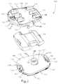
- FIG. 1illustrates an anterior view of two cervical vertebrae with an artificial disc prosthesis implanted between the vertebrae, the artificial disc prosthesis comprising a superior end plate, a nucleus which provides 6° of lordotic correction, and an inferior end plate;
- FIG. 2illustrates an exploded top perspective view of the superior end plate, nucleus, and inferior end plate of FIG. 1 ;
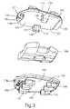
- FIG. 3illustrates an exploded bottom perspective view of the superior end plate, nucleus, and inferior end plate of FIG. 1 ;
- FIG. 4Aillustrates a top perspective view of the superior end plate of FIG. 1
- FIG. 4Billustrates a lateral view of the superior end plate of FIG. 1 ;
- FIG. 5Aillustrates a top view of the nucleus of FIG. 1
- FIG. 5Billustrates a bottom view of the nucleus of FIG. 1 ;
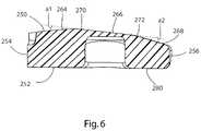
- FIG. 6illustrates a lateral cross-sectional view of the nucleus of FIG. 1 ;
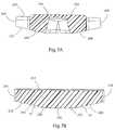
- FIG. 7Aillustrates a posterior cross-sectional view of the nucleus of FIG. 1
- FIG. 7Billustrates a posterior cross-sectional view of the nucleus of FIG. 1 ;
- FIG. 8illustrates a lateral view of the artificial disc prosthesis of FIG. 1 in a preferred orientation
- FIG. 9Aillustrates a lateral view of an artificial disc nucleus that provides 0° of lordotic correction
- FIG. 9Billustrates a lateral view of an artificial disc nucleus that provides 3° of lordotic correction
- FIG. 9Cillustrates a lateral view of an artificial disc nucleus that provides 6° of lordotic correction
- FIG. 10Aillustrates a sagittal cross-sectional view of the artificial disc prosthesis of FIG. 1 in a preferred orientation in the flexion-extension degree of freedom
- FIG. 10Billustrates a sagittal cross-sectional view of the artificial disc prosthesis of FIG. 1 in extension;
- FIG. 11Aillustrates a posterior cross-sectional view of the artificial disc prosthesis of FIG. 1 in a preferred orientation in the lateral bending degree of freedom
- FIG. 11Billustrates a posterior cross-sectional view of the artificial disc prosthesis of FIG. 1 in lateral bending;
- FIG. 12Aillustrates a lateral view of the artificial disc prosthesis of FIG. 1 in flexion and lateral bending
- FIG. 12Billustrates an anterior view of the artificial disc prosthesis of FIG. 1 in flexion and lateral bending
- FIG. 13Aillustrates a top view of the nucleus and inferior end plate of FIG. 1 in a neutral orientation with respect to rotation about a cephalad-caudal axis
- FIG. 13Billustrates the a top view of the nucleus and inferior end plate of FIG. 1 in an axially rotated orientation
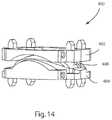
- FIG. 14illustrates an anterior perspective view of an alternative embodiment of an artificial disc prosthesis comprising a superior end plate, a nucleus, and an inferior end plate;
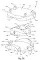
- FIG. 15illustrates an exploded bottom perspective view of the superior end plate, nucleus, and inferior end plate of FIG. 14 ;
- FIG. 16illustrates an exploded top perspective view of the superior end plate, nucleus, and inferior end plate of FIG. 14 ;
- FIG. 17Aillustrates a sagittal cross-sectional view of the artificial disc prosthesis of FIG. 14 in a neutral low-energy orientation with respect to the flexion-extension degree of freedom
- FIG. 17Billustrates a sagittal cross-sectional view of the artificial disc prosthesis of FIG. 14 in flexion
- FIG. 17Cillustrates a sagittal cross-sectional view of the artificial disc prosthesis of FIG. 14 in extension;
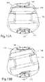
- FIG. 18illustrates an anterior perspective view of an alternative artificial disc prosthesis comprising a superior end plate, a nucleus, a retention element, and an inferior end plate;
- FIG. 19illustrates an exploded top perspective view of the superior end plate, nucleus, retention element, and inferior end plate of FIG. 18 ;
- FIG. 20illustrates an exploded bottom perspective view of the superior end plate, nucleus, retention element, and inferior end plate of FIG. 18 ;
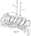
- FIG. 21illustrates a portion of a spine with a partial discectomy between two cervical vertebrae
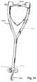
- FIG. 22illustrates a guide tool aligned with the midline of the portion of the spine of FIG. 21 ;
- FIG. 23Aillustrates a perspective view of the guide tool of FIG. 22
- FIG. 23Billustrates a lateral view of a head of the guide tool of FIG. 22
- FIG. 23Cillustrates a perspective lateral view of the head
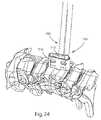
- FIG. 24illustrates an awl inserted through the guide tool of FIG. 22 ;
- FIG. 25illustrates a perspective view of the awl of FIG. 24 ;
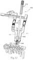
- FIG. 26illustrates a cross-sectional sagittal view of the guide tool and spinal portion of FIG. 22 , with a driver tool driving a pin into a vertebral body;
- FIG. 27illustrates the spinal portion of FIG. 21 , with two pins driven into adjacent vertebral bodies
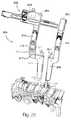
- FIG. 28illustrates an adjustable retainer secured to the pins of FIG. 27 ;
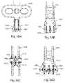
- FIG. 29Aillustrates a rack and pinion system of the adjustable retainer of FIG. 28 , with a pawl in a neutral position
- FIG. 29Billustrates the rack and pinion system with the pawl in a position to allow only compression
- FIG. 29Cillustrates the rack and pinion system with the pawl in a position to allow only distraction
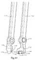
- FIG. 30illustrates the adjustable retainer of FIG. 28 and a separate distractor tool
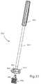
- FIG. 31illustrates a rasp tool which may be used with the adjustable retainer of FIG. 28 ;
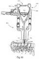
- FIG. 32illustrates the adjustable retainer of FIG. 28 guiding a planer tool
- FIG. 33illustrates the adjustable retainer of FIG. 28 and a feeler tool
- FIG. 34illustrates a trial
- FIG. 35illustrates an exploded view of the trial of FIG. 34 ;
- FIG. 36illustrates the trial of FIG. 34 guided by the adjustable retainer of FIG. 28 ;
- FIG. 37illustrates an implant inserter gripping the implant of FIG. 1 ;
- FIG. 38Aillustrates a lateral view of a distal end of the implant inserter of FIG. 37
- FIG. 38Billustrates a top view of the distal end of the implant inserter
- FIG. 38Cillustrates an end view of the distal end of the implant inserter
- FIG. 38Dillustrates a perspective view of the distal end of the implant inserter in an open configuration
- FIG. 39illustrates a top cross-sectional view of the distal end of the implant inserter and implant of FIG. 37 ;
- FIG. 40Aillustrates a tamp
- FIG. 40Billustrates an enlarged view of the distal end of the tamp
- FIG. 41is a cross-sectional view of the tamp of FIG. 40 fitted to the implant of FIG. 1 ;
- FIG. 42illustrates a remover tool gripping the implant of FIG. 1 ;
- FIG. 43is an enlarged view of a distal end of the remover tool, and implant of FIG. 42 ;
- FIG. 44is an exploded view of the distal end of the remover tool of FIG. 42 .
- the present inventionrelates to systems and methods for the treatment of disc disease and spinal deformities with an artificial disc replacement.
- Those of skill in the artwill recognize that the following description is merely illustrative of the principles of the invention, which may be applied in various ways to provide many different alternative embodiments. This description is made for the purpose of illustrating the general principles of this invention and is not meant to limit the inventive concepts in the appended claims.
- the spinefollows natural curves, which promote proper sagittal and coronal balance (flexibility) and allow for balanced load sharing between the vertebrae.
- curvesinclude the cervical, thoracic, lumbar and sacral regions of the spine.
- the cervical and lumbar regionsare naturally lordotic, or curved convexly in the anterior direction.
- the intradiscal space and vertebral body heightmay be different for different people.
- Each intradiscal spacehas anterior and posterior regions.
- An artificial disc in the cervical, thoracic and lumbar regions that maintains the same height from the anterior to the posteriormay promote an abnormal alignment, resulting in additional stress at the anterior or posterior portions of an adjacent disc. It may also result in an uneven load distribution across the device and cause an excessive amount of relative motion, wear debris and early failure.
- nucleus and coreare used interchangeably to refer to an artificial intervertebral device that replaces a damaged natural spinal disc.
- the artificial coremay be provided alone or in combination with a superior end plate for attachment to an upper vertebra or an inferior end plate for attachment to a lower vertebra or both.
- upper and lowerare used herein to refer to the vertebrae on either side of the disc to be replaced, or a surface on a part in the position shown in the referenced drawing.
- a “superior” plateis affixed to an upper vertebra and an “inferior” plate is affixed to a lower vertebra of a functional spinal unit.
- the terms vertical and horizontalare used herein relative to a standing human being in the anatomical position.
- the term “anterior”refers to the region towards the front and the term “posterior” refers to the region towards the back.
- the term “sagittal”refers to regions on either side of the central midline axis of a standing human being.
- the term “sagittal plane” used hereinrefers to a vertical plane extending along the central midline axis of the vertebral bodies of the spine, dividing the body into left and right lateral regions.
- the term “coronal plane”refers to a vertical plane extending along the central midline axis of the vertebral bodies of the spine, dividing the body into anterior and posterior regions through the center of the vertebral bodies.
- cephalad-caudal axisrefers to a vertical axis which extends along the central midline axis of the vertebral bodies of the spine.
- asymmetricalis used herein to refer to an axis of maximum height that is not placed centrally or to a nucleus or total disc replacement (TDR) not having its maximum vertical axis placed centrally.
- the maximum heightis not situated or pivoted at a center line of symmetry so that the TDR comprises regions that are not exactly the same in shape or size as other regions on the other side of a line of symmetry.
- the location of maximal load bearingis located in a non-central location.
- the termmay analogously apply to joint prostheses in which an axis of maximum height is not located centrally on a substantially convex bearing surface, or the axis of maximum depth of a depression is not placed centrally on a substantially concave bearing surface.
- normal alignmentis used herein to refer to the natural positioning of functional components of a healthy joint, relative to one another and/or the surrounding tissues. Normal alignment may refer to the static position of a joint at rest, wherein no stress or pressure is placed on the joint, and it may also refer to the dynamic position of a joint under natural mechanical stress such as during flexion or extension. Normal alignment may also be referred to as natural, healthy, or proper alignment. “Preferred” or “desired” alignment are used herein to refer to joint alignment that may be natural, or corrected, but places the joint components in a functional or desired position. The terms “preferred orientation” or “preferred relative orientation” used herein also refer to component alignment that may be natural, or corrected, in which the joint components are in a functional or desired position.
- preferred relative orientationmay refer to an orientation about a single axis, or about multiple axes.
- an artificial disc implantmay be designed to establish a preferred relative orientation about an axis extending medial-laterally to provide a preferred anterior-posterior angulation that mimics the appropriate lordosis or kyphosis of the joint motion segment.
- an artificial disc implantmay be designed to establish a preferred relative orientation about an axis extending generally anterior-posteriorly to provide a preferred medial-lateral angulation that provides the desired degree of lateral bending.
- Such lateral bendingmay be zero degrees, reflecting the straightness of a healthy spine, or may be nonzero to the left or right to provide correction for various pathologies including scoliosis.
- an artificial disc implantmay be designed to provide a preferred relative orientation about both of the medial-lateral and anterior-posterior axes to encourage proper lordosis or kyphosis while also encouraging the desired lateral bending.
- a preferred relative orientationmay also be a low energy position in which the joint is naturally encouraged to remain, in contrast to a point of resistance such as a motion stop.
- orientation featureis a feature present on one or more joint components that help the components establish a preferred relative orientation.
- opposing bearing surfaces on joint componentsmay include flattened sections, which cooperate to urge the components toward attaining a preferred relative orientation.
- Matching curved surfaces which align better in a preferred relative orientationmay also be orientation features.
- Other configurations of orientation featuresmay be possible in addition to flat and curved surfaces.
- nucleus body designs with a completely rounded surfacehave issues with reliably maintaining correction when exposed to the variable forces of the head and neck.
- This sectionwill be referred to as a flattened section, which is meant to refer to any contour that is not the same as the adjacent surface(s) of the nucleus.
- a flattened surfacecan be planar or it can have other shapes such as a slight convex or concave shape with a radius of curvature different from the adjacent surface.
- Such a flattened surfacecould also be in the shape of a compound curve or other complex shape.
- a flattened sectionmay also refer to a rectilinear portion of a two dimensional shape.
- the flattened segmentcan be angled relative to the superior end plate of the inferior vertebral body with the height of the anterior part being greater than the height of the posterior part.
- the overall shape of the nucleus bodyis still asymmetric, but the flattened segment is incorporated to provide a reliable correction of the deformity.
- This flattened segmentprovides stabilization to resist the moments acting through the nucleus, i.e., if the flat is not of adequate size, there may be a tendency for the correction to disappear in the presence of an anterior load or for a hyper-lordotic over correction in the presence of a posterior load (during lordotic correction).
- An additional advantage of incorporating a flattened segment in the nucleusis to provide surface contact over that area during small motions about the resting, neutral position of the device, which may help reduce the stresses and potentially wear of the device.
- This flattened surfacecan be angled relative to the superior end plate of the inferior vertebral body (or vice versa, or both), with the height of the anterior end being greater than the height of the posterior end when lordotic correction is sought.
- the overall shape of the corecan still be asymmetric, but the flattened surface can be incorporated to provide a reliable correction of the deformity.
- the coremay have flattened sections but be symmetric and the endplates may be asymmetric or angled to provide the lordotic correction.
- the inventionincludes a novel artificial disc that provides the normal range of motion of the natural intervertebral disc, along with the ability to correct deformity of the spine.
- the proposed discallows for semi-constrained range of motion of the functional spinal unit. It reproduces the kinematics of the pre-operative normal spine in all motions.
- the proposed discallows for independent & mobile centers of rotation in the flexion-extension and lateral-bending motions, which is unique to this device but an inherent characteristic of the natural spine. It possesses maximum durability and biocompatibility, and a means for integrating itself into the spine bony structure for long-term stability. Its insertion is safe, simple, and surgical time is not compromised compared with the current procedures. In contrast to the existing disc replacement systems, it will allow the surgeon to correct deformity while maintaining natural kinematics of the spine.
- an artificial disccomprises a nucleus that is not geometrically symmetrical.
- the discmay have a maximum vertical axis that is not located at the geometric center of the disc.
- the maximum vertical axismay be located toward the front of the disc, the rear of the disc and/or on one side of the disc.
- the positioning of the maximum vertical height and load bearing capabilityis chosen depending on the type of deformity that needs to be corrected.
- the present inventionalso provides methods for the treatment of disc/vertebral body disease, lordosis, kyphosis and scoliosis using an asymmetric artificial disc.
- nucleusor core may be interchanged and revised intra-operatively and post-operatively. Instruments can be used to gauge the need for and amount of correction and the appropriate implant can then be inserted. By introducing correction into the nucleus, the surgeon benefits from flexibility, ease of insertion and revisability that present systems do not provide.
- Artificial discs of the present inventioncan be provided with various degrees of deformity correction.
- the surgeoncan choose a disc having the appropriate correction for the patient.
- a method of treating a spinal deformitycomprises preparing a spinal segment for implantation of an artificial disc, determining the desired angle of the intervertebral space, selecting an artificial nucleus having the desired dimensions, affixing a superior end plate to the upper vertebra, affixing an inferior end plate to the lower vertebra and inserting the selected nucleus between the superior and inferior end plates.
- the assembled unit of end plate-nucleus-end platemay be inserted in unison.
- the configuration of the nucleus in this pre-assembled constructcan be determined by the intra-operative measurement tools, or with pre-operative calculations. Pre-operative planning techniques and instruments may also be able to determine the size and orientation of this device for insertion.
- a major advantage of the present systemis that the artificial disc can be more easily and rapidly inserted and the nucleus can be changed or revised in accordance with the magnitude of the deformity being corrected. This is especially useful in children and young adults where the alignment of the spine changes over time.
- an asymmetric nucleus adapted for lordotic correction of the cervical spineis provided.
- the surgeoncan restore lordosis to the cervical spine while maintaining motion.
- the nucleusmay be composed of a low friction elastomer such as polyurethane, polycarbonate-polyurethane, a polymer such as polyethylene (particularly ultra-high molecular weight polyethylene or UHMWPE), a suitable ceramic, metals, metal matrix composites such as titanium carbide, or metal alloys such as titanium or a titanium alloy, chrome-cobalt-molybdenum (CoCrMo), cobalt chrome, stainless steel, or other suitable materials.
- a low friction elastomersuch as polyurethane, polycarbonate-polyurethane, a polymer such as polyethylene (particularly ultra-high molecular weight polyethylene or UHMWPE), a suitable ceramic, metals, metal matrix composites such as titanium carbide, or metal alloys such as titanium or a titanium alloy, chrome-cobalt
- the nucleushas a generally trapezoidal geometric design, with varying degrees of lordosis incorporated into it by utilizing an axis of maximum height anterior to the geometric center of the nucleus.
- the anterior height of the nucleusvaries, depending on the extent of lordotic correction needed.
- the nucleusmay be available in various lordotic angles, e.g. 0, 3° and 6°, as well as differing heights (e.g., 4, 6 and 8 mm).
- a set of instrumentscould be inserted to confirm the lordotic correction, but these may also be used as confirmation for other types of pre-surgical planning techniques and instrumentation.
- intra-operative instrumentsmay be used as confirmation for other types of pre-surgical planning techniques and instrumentation.
- the implantconsists of three pieces; a superior end plate, an inferior end plate, and the nucleus.
- the end plateswill be made in differing sizes to accommodate differences in anatomy. These may be fabricated of titanium, titanium carbide, or a titanium alloy, cobalt-chrome-molybdenum (CoCrMo), cobalt chrome, stainless steel, metal matrix composites, or other materials suitable for spinal prosthetic inserts. They may also be mainly fabricated from one or more materials and utilize a separate coating surface or material layer for optimizing mechanical and wear performance. Coatings could be used for lubricity, low-friction, enhanced hardness, low surface energy, roughness, or other desirable characteristics for an articulating joint.
- the end platescan have two distinct surfaces.
- the flat surface of each end plate, which contacts the vertebral body end plate,is capable of accommodating bony ingrowth and incorporates a suitable coating, such as porous titanium, a calcium phosphate, or includes other types of known surfaces that promote bony ingrowth for long-term stability.
- the end platescan also have one or more parasagittal keels or teeth that provide immediate fixation.
- FIG. 1illustrates an embodiment of an artificial disc replacement implanted in an intervertebral space between two adjacent vertebrae in a portion of a spine.
- Artificial disc prosthesis 100comprises a superior end plate secured to a superior vertebral body 2 , an inferior end plate 104 secured to an inferior vertebral body 4 , and a nucleus 106 positioned between the superior and inferior endplates.
- Securing an end plate to a vertebral bodycomprises coupling the end plate to the vertebral body so that it remains in place at least long enough for bony ingrowth to occur.
- the disc prosthesis 100comprises a plurality of articulating surfaces which form articulating joints, permitting restoration of intervertebral motion including flexion/extension, anterior/posterior translation, lateral bending and axial rotation, between the end plates.
- the disc prosthesis 100further comprises orientation features which may allow the joints to remain in a preferred orientation relative to one or more axes, which may be a neutral low energy position which the joint is naturally encouraged to maintain.
- FIGS. 2 and 3illustrate exploded perspective views of the disc replacement 100 ; FIG. 2 from a cephalad-lateral perspective and FIG. 3 from a caudal-lateral perspective.
- Various features of the end plates 102 , 104are visible in these views.
- Each end plate 102 , 104is generally trapezoidal in shape, although alternative shapes such as rectangular, circular, oval or kidney, among other, are contemplated for other embodiments of the invention.
- Superior end plate 102comprises an end plate body 110 with an anterior end 112 , posterior end 114 , left lateral side 116 , right lateral side 118 , superior side 120 and inferior side 122 .
- the superior side 120has a bone engagement surface 124 which is essentially flat, enabling it to easily contact the surface of the natural vertebral end plate.
- a flat bone engagement surfacemay eliminate extra surgical time needed to prepare the vertebrae to the appropriate shape to accommodate the end plate.
- other embodiments of the inventionmay include end plates which are do not have flat bone engagement surfaces, but shaped surface which may be generally concave or convex.
- the bone engagement surfacecan be porous and incorporate a suitable treatment, such as porous titanium, a calcium phosphate or other types of known treatments such as coatings, plasma sprays, and structural changes to the surface, that promote bony ingrowth or ongrowth for long-term stability.
- An anterior portion 126 of the end plate 102may not incorporate the ingrowth treatment, to allow for easier instrument insertion and gripping.
- a posterior angled portion 128 of the bodyslopes caudally at an acute angle from the remainder of the body 120 , allowing for ease of insertion of the prosthesis into the intervertebral space during implantation.
- a plurality of first teeth 130 and second teeth 131may project outwardly from the bone engagement surface 124 .
- the inferior side 122 of the superior end plate 102comprises an essentially planar articular surface 132 .
- Two flanges, a left flange 134 and a right flange 135protrude caudally from the articular surface, positioned centrally along the lateral sides 116 , 118 of the end plate.
- the flanges 134 , 135are positioned to fit into gaps formed by notches formed in the nucleus 106 .
- Other embodimentsmay include flanges positioned at the corners of the end plates, or at other locations along the lateral sides.
- a sloped surface 136is formed on the inferior side of left flange 134
- a sloped surface 137is formed on the inferior side of right flange 135 .
- the sloped surfaces 136 or 137do not contact a superior surface of the inferior end plate, as an inferior surface the nucleus instead contacts the superior surface of the inferior end plate to provide a soft stop to the lateral bending motion.
- the heights of the flanges 134 , 135may vary, and the slope of the sloped surfaces 136 , 137 may vary.
- An anterior-posterior dimension of the flanges 134 , 135may be less than an anterior-posterior dimension of the gaps in the nucleus 106 , allowing constrained anterior-posterior translation of the end plate 102 relative to the nucleus.
- a soft stopmay occur when a first component, such as a nucleus, comprising material such as UHMWPE contacts a second component, such as an end plate, comprising a harder material such as titanium or other metals, in a way as to prevent further motion of the first component along the same direction.
- a first componentsuch as a nucleus
- a second componentsuch as an end plate
- a harder materialsuch as titanium or other metals
- the moving first componentmay comprise the harder material
- the second componentmay comprise the relatively softer material.
- An anterior retention member 140is formed along the anterior side of the end plate 102 , protruding caudally toward the inferior end plate 104 .
- the anterior retention member 140may assist in preventing displacement of the nucleus from between the end plates, as the member 140 is positioned anterior to the anterior edge of the nucleus 106 .
- An inner edge 142 of the member 140is angled to permit limited rotation of the nucleus relative to the end plate 102 to accommodate device axial rotation. This inner edge 142 also serves as an axial rotation stop to limit the amount of axial rotation.
- the inner edge 142is also dovetailed to engage gripping arms of a prosthesis insertion tool.
- a pocket 144is formed into the anterior portion of the member 140 and serves as a receptacle for instrumentation during implantation, revision or removal of the prosthesis. After implantation of the prosthesis and during flexion of the spine, the anterior member 140 does not contact the inferior end plate 102 , as the nucleus contacts the inferior end plate, to provide a motion stop before the member 140 could contact the inferior end plate.
- Other embodiments of the inventionmay include multiple anterior members formed on the superior end plate, or no anterior members formed on the superior endplate.
- Inferior end plate 104comprises an end plate body 150 with an anterior end 152 , posterior end 154 , left lateral side 156 , right lateral side 158 , superior side 160 and inferior side 162 .
- An essentially planar superior articular surface 164extends across the end plate body 150 .
- a posterior retention member 166is formed at the posterior end 154 , protruding from the superior side 160 .
- the posterior retention memberis bounded by an inner edge 168 which is angled to permit limited axial rotation of the nucleus 106 relative to the end plate 104 , and by a superior surface 169 which may be angled laterally and posteriorly to allow lateral bending during extension.
- An anterior retention member 170 with an angled inner edge 172is located along the anterior end 152 , protruding from the superior side 160 toward the superior end plate 102 .
- a pocket 174is formed in the retention member 170 , which may receive instrumentation during implantation, revision or removal of the prosthesis.
- a superior surface 176 of the retention member 170may be angled laterally and anteriorly to permit lateral bending during flexion.
- a pin, or post 180protrudes from the superior side 160 in a cephalad direction toward the superior end plate 102 .
- the post 180may be located in a geometric center of the inferior end plate 104 , or it may be displaced from the geometric center.
- the location of the post 180 , and a corresponding pocket in the nucleus,determines the cephalad-caudal axis about which the nucleus and the opposing end plate may rotate relative to the inferior end plate 102 .
- the post 180comprises a circumferential wall 182 with a spherical shoulder 183 , which may articulate with a wall of the nucleus pocket.
- the postcould have a non-cylindrical shape such as a square or triangle, among others.
- the post 180also cooperates with the nucleus pocket to permit lateral bending simultaneously with axial rotation.
- the inferior side 162 of the inferior end plate 104comprises a planar bone engagement surface 186 , on which one or a plurality of teeth 130 , 131 may be formed.
- An anterior portion 188may be free of bone ingrowth or ongrowth treatments to allow for engagement with instrumentation.
- a posterior angled portion 190 of the bodyslopes cephaladly at an acute angle from the remainder of the bone engagement surface 186 , again allowing for ease of insertion of the prosthesis into the intervertebral space during implantation.
- a plurality of bone engagement featurescomprising self-cutting first teeth 130 and second teeth 131 , may be formed on the bone engagement surfaces 124 , 186 of the superior and inferior end plates.
- Teeth 130 , 131have sharply pointed leading edges, which cut into the vertebral bodies during insertion and may eliminate extra preparation steps such as pre-cutting or reaming grooves into the surfaces of the vertebral bodies.
- Each second tooth 131may be positioned directly behind, or anterior to, a first tooth 130 .
- Each first tooth 130has a narrowly angled cutting point 202 , and is positioned with the point oriented toward the posterior end 114 of the endplate 102 .
- the sharp cutting point 202 on each first tooth 130cuts a track into the surface of the vertebral body.
- the second tooth 131follows in the track cut by the first tooth 130 , and a wider cutting point 204 on the second tooth widens the track.
- Each first tooth 130has a pointed apex 206 positioned atop the tooth, supported by a pair of support walls 208 and an end wall 210 .
- the support walls 208are angled toward one another from the bone engagement surface 124 or 186 to the apex 206 . This angulation advantageously permits a solid press-fit as the tooth penetrates the vertebral body, providing immediate anchorage.
- the angled walls 208also allow some subsidence of the end plate 102 into the vertebral body after implantation, without the risk of loosening from the vertebral body.
- the end wall 210may be vertical or near vertical, promoting retention in the vertebral body and prevention of unintended withdrawal from the vertebral body. In other embodiments of the invention, the walls 208 may not be angled but instead parallel to one another.
- Each second tooth 131comprises the wide cutting point 204 , two angled support walls 212 and an end wall 216 which support a pointed apex 214 .
- the second teeth 131are similar in configuration to the first teeth 130 ; however particular dimensions such as wall height and the angle and width of the cutting point may vary. For example, as shown in FIG. 4A , second tooth 131 is laterally wider than first tooth 130 , while the cutting point 202 of first tooth 130 is narrower than the cutting point 204 of second tooth 131 . Looking at FIG. 4B , the support walls 212 and apex 214 of the second tooth 131 are taller, providing a larger vertical dimension than the support walls 208 and apex 206 of the first tooth 130 .
- a posterior leading edge 218 of first tooth 130is more gently sloped than a posterior leading edge 220 of second tooth 131 , which may aid in insertion. All first and second teeth 130 , 131 may incorporate the same bone ingrowth or ongrowth treatments as the bone engagement surfaces 124 , 186 .
- Both end plates 102 , 104are general laterally symmetrical; however in alternative embodiments one or both of the endplates could have a maximum vertical dimension located on one lateral side to provide a scoliotic correction. Similarly, one or both of the endplates could have an anteriorly located maximum vertical dimension to provide a lordotic correction, or a posteriorly located maximum vertical dimension to provide a kyphotic correction. It is appreciated that specific features of the end plates, including but not limited to bone engagement features, motion stops, instrument recesses, and posts, may be swapped, inverted or reversed such that features found on the superior end plate may be instead located on the inferior end plate, and vice versa. Additionally, in alternative embodiments features found on end plates may instead be located on the nucleus, and vice versa.
- FIGS. 5A , 5 B, 6 , 7 A, and 7 Billustrate various views of the disc nucleus 106 .
- the nucleushas a generally rounded trapezoidal shape, although alternate embodiments may have other shapes.
- the nucleus 106comprises a superior side 250 , an inferior side 252 , an anterior end 254 , a posterior end 256 , a left lateral side 258 and a right lateral side 260 .
- the superior side 250comprises a nuclear superior articular surface 262 , which further comprises three planar portions: an anterior planar portion 264 , a middle planar portion 266 , and a posterior planar portion 268 .
- a first curvate transition portion 270lies between the anterior planar portion 264 and the middle planar portion 266
- a second curvate transition portion 272lies between the middle planar portion 266 and posterior planar portion 268 .
- the three planar portionsare perpendicular to a sagittal plane of the vertebral bodies when the implant is properly implanted in an intervertebral space.
- the planar portionsare not co-planar with respect to one another, although an alternative embodiment of the invention could include one or more co-planar planar portions.
- An angle a 1the angle between the anterior 264 and middle 266 planar portions, is acute and may be unequal to an angle a 2 , the angle between the middle 266 and posterior 268 planar portions.
- angles a 1 and a 2may be equal.
- the nucleus inferior side 252comprises an inferior articular surface 280 , which, like the superior articular surface, also comprises three planar surfaces separated by two curvate transition portions.
- a right planar portion 284is separated from a central planar portion 286 by a first curvate transition portion 290
- the central planar portion 286is separated from a left planar portion 288 by a second curvate transition portion 292 .
- the three planar portionsare not co-planar. When the prosthesis is properly implanted in an intervertebral space, the planar portions are perpendicular to a coronal plane of the vertebral bodies when the implant is properly implanted in an intervertebral space.
- angles b 1 and b 2may be unequal to provide a scoliotic correction.
- the left notch 300defines a left gap 304 , through which left flange 134 extends when the nucleus is positioned between the end plates 102 , 104 .
- the right notch 302defines a right gap 306 , through which the right flange 135 may extend.
- Each gap 304 , 306is wider in an anterior-posterior dimension than its respective motion stop, to allow translation of the superior end plate 102 relative to the nucleus 106 and the inferior end plate.
- FIG. 8is a lateral view of the left side of the prosthesis, illustrating the relationship of the left flange 134 to the left notch 300 as the prosthesis is in a low-energy neutral position with respect to rotation about both an anterior-posterior axis and a medial-lateral axis. Arrows indicate anterior-posterior translation of the superior end plate 102 .
- a recess 296may be formed in the anterior end 254 toward the superior side 250 of the nucleus. The recess is shaped to receive the anterior retention member 140 of the superior end plate 102 during translation of the superior end plate.
- a pocket 310is formed as a recess into the inferior side 252 of the nucleus 106 , and is shaped to receive the post 180 .
- Pocket 310is shaped as a tapered slot, with a medial-lateral maximum opening dimension 312 which is greater than an anterior-posterior maximum opening dimension 314 .
- a support wall 316which circumscribes the pocket 314 tapers outward from an end wall 318 of the pocket to its opening 319 .
- the support wall 316may articulate with the circumferential wall 182 of the post 180 .
- the ovoid shape and sloping support wallpermit the nucleus 106 and the superior end plate 102 freedom to move relative to the post 180 during lateral bending.
- Prosthesis 100comprises a combination of articular surfaces and motion stops which allow the flexion-extension rotational degree of freedom and anterior-posterior translation on a first joint and the lateral bending and axial rotation degrees of freedom on a second joint.
- the centers of rotation for each individual rotational degree of freedommay be shared, or each rotational degree of freedom may have a different center of rotation.
- the first jointcomprises the interface between the nuclear superior articulation surface 262 and the inferior articular surface 132 of the superior end plate 102 .
- the nuclear superior articulation surface 262articulates with the inferior articular surface 132 .
- the first jointalso permits anterior-posterior translation of the superior end plate 102 relative to the nucleus 106 and the inferior end plate 104 .
- the second jointcomprises the interface between the nuclear inferior articulation surface 280 and the superior articular surface 164 of the inferior end plate 104 .
- the nuclear inferior articulation surface 280articulates with the superior articular surface 164 .
- Left lateral bending motionis limited when the left planar portion 288 contacts the superior articular surface 164
- right lateral bending motionis limited when the right planar portion 284 contacts the superior articular surface 164 .
- Axial rotationalso occurs on the second joint, as the nuclear inferior articulation surface 280 rotates relative to the superior articular surface 164 around the axis of the post 180 . This axial rotation motion may be limited by the angled inner edges of the anterior 170 and posterior 166 retention members on the inferior end plate 104 .
- FIGS. 9A , 9 B, and 9 Calternate embodiments of artificial disc nuclei are illustrated in lateral cross-sectional views.
- FIG. 9Aillustrates a nucleus 350 in which the upper and lower surfaces 352 and 354 are parallel to each other and an angle between them is 0 degrees. In this nucleus, an axis of greatest height 356 falls in the center of the disc.
- FIG. 9Ba nucleus 360 that provides 3° of lordotic correction is illustrated.
- FIG. 9Cillustrates another artificial disc nucleus 370 having 6° of lordotic correction. When deformity correction is provided as shown in FIGS.
- the axis of greatest height 356may shift to a location that is offset from the geometric center of the nucleus. If the anterior/posterior directions are reversed, a kyphotic correction is provided. It is apparent that the nucleus can be adjusted to provide various degrees of correction and, in certain cases, if no degree of correction is needed. Nuclei 350 , 360 , 370 may be combined with end plates 102 , 104 or other end plates to form artificial disc prostheses. Nucleus 106 comprises 6° of lordotic correction.
- the middle planar portions on each nuclear articulation surfacemay provide each joint with a preferred orientation or stable low energy position.
- a low energy positionis not the same as a motion limited position, from which motion of the joint in a particular direction is prohibited after a certain point, i.e. past a motion stop. Instead a low energy position is an orientation of a joint into which the joint tends to settle, and energy must be expended to move the joint out of to the low energy position.
- FIG. 10Ais a sagittal cross-sectional view of prosthesis 100 with a joint between the superior end plate 102 and the nucleus 106 in a low energy position in the flexion-extension degree of freedom.
- Inferior articular surface 132is in surface contact with middle planar portion 266 , providing a preferred orientation and low energy position of the prosthesis across a coronal plane of the superior and inferior end plates 102 , 104 .
- sufficient energywill have to be applied to the superior end plate 102 to overcome resistance and rotate anteriorly across the coronal plane over the first curvate transition portion 270 in flexion or rotate posteriorly over the second curvate transition portion 272 in extension.
- FIG. 10Billustrates the prosthesis of 10 A with the joint in extension.
- the superior end plate 102is tilted back such that inferior articular surface 132 is in contact with posterior planar portion 268 , the extension motion stop.
- FIGS. 11A and 11Billustrate coronal cross-sectional views of prosthesis 100 from a posterior perspective, showing the prosthesis in a low energy position in the lateral bending degree of freedom, and in a laterally bent position, correspondingly.
- the inferior articular surface of the nucleusis in a preferred orientation, in unbroken contact with the superior articular surface 164 of the inferior end plate 104 surrounding the post 180 .
- sufficient energywill have to be applied to laterally rotate the nucleus across the sagittal plane enough to lift one side out of contact with the superior articular surface 164 .
- This positioncan be seen in FIG. 11B , at the lateral bending stop.
- FIG. 12A and 12Billustrates the prosthesis 100 during flexion combined with lateral bending.
- FIG. 12Ais a left lateral view, showing superior end plate 102 tilted forward in flexion, and also shifted forward in translation, and nucleus 106 is in right lateral bending.
- FIG. 12Bis an anterior view, showing superior end plate 102 in flexion and anterior translation and nucleus 106 tilted right in lateral bending.
- anterior planar portion 264 of the nucleusis in contact with the inferior articular surface 132 of the superior end plate 102 , providing a soft stop to flexion.
- Right planar portion 284 of the nucleusis in contact with the superior articular surface 164 of the inferior end plate 104 , providing a soft stop to lateral bending.
- FIGS. 13A and 13Billustrate axial rotation of the nucleus 106 relative to the inferior end plate 104 .
- superior end plate 102is not shown.
- FIG. 13Aillustrates nucleus 106 in a central, non-rotated position
- FIG. 13Bshows the nucleus 106 rotated to the left.
- the angled inner edges 172 , 168 of motion stops 170 , 166limit the rotational motion.
- the present inventionallows axial rotation to occur in combination with flexion-extension and/or lateral bending and/or anterior-posterior translation.
- one alternate embodimentmay include flexion-extension and lateral bending in one joint and axial rotation in the other joint.
- Another embodimentmay include flexion-extension and axial rotation in one joint, and lateral bending in the other joint.
- FIG. 14illustrates an alternative embodiment of the invention, an artificial disc prosthesis 400 comprising a superior end plate 402 , an inferior end plate 404 , and a core, or nucleus 406 .
- the superior end platecomprises a superior surface adapted for bony contact and an at least partially cylindrical surface on an inferior surface to articulate a superior surface of the nucleus.
- the nucleusincludes an at least partially cylindrical superior surface and a planar inferior surface and a cylindrical outer surface.
- the inferior end platecomprises a planar superior surface which articulates with the inferior surface of the nucleus, and an inferior surface that is adapted for bony contact and a cylindrical inner surface.
- a first joint of the prosthesisallows flexion-extension and lateral bending degrees of freedom, and a second joint allows the axial rotation degree of freedom.
- FIG. 15illustrates an exploded view of prosthesis 400 from an anterior-inferior perspective
- FIG. 16illustrates an exploded view of the prosthesis from a posterior-superior perspective
- Superior end plate 402comprises an anterior end 410 , a posterior end 412 , a left lateral side 414 and a right lateral side 416 .
- a gripping recess 417may be located on either or both lateral sides.
- a superior bone engagement surface 418is adapted for bony contact, and a plurality of self-cutting teeth 420 and/or 421 may be distributed on the bone engagement surface 418 . Both the bone engagement surface and the teeth may incorporate bone ingrowth or ongrowth treatments as previously set forth.
- An inferior articular surface 424comprises a flattened portion shaped as a partial cylinder.
- a post 430extends caudally from the inferior articular surface, comprising post articular surface 432 which may incorporate a flattened section portion.
- Flattened lateral portions 426 , 428which may be planar, flank the inferior articular surface 424 .
- Inferior end plate 404comprises an anterior end 440 , a posterior end 442 , a left lateral side 444 and a right lateral side 446 .
- Gripping recesses 417may be located on the lateral sides.
- An inferior bone engagement surface 450which may be planar, is on an inferior side 448 , and may comprise a plurality of self-cutting teeth 420 , 421 .
- the teeth and bone engagement surfacemay comprise areas incorporating bone ingrowth or bone ongrowth treatments.
- a planar superior articular surface 456is on a superior side 452 of the end plate.
- An anterior motion stop 460extends along the anterior end 440 and cephalad toward the superior end plate 402 .
- An inner surface 462is cylindrical to correspond with a cylindrical outer edge of the nucleus 406
- an upper surface 464is shaped as a portion of a cylinder to mate with the inferior articular surface 424 of the superior end plate 402 during flexion.
- a posterior motion stop 466similarly comprises a cylindrical upper surface 468 to mate with the inferior articular surface 424 during extension.
- the posterior motion stop 466further comprises a cylindrical inner surface 470 , and an undercut 472 which is shaped to receive a tab on the nucleus 406 .
- Right and left lateral motion stops 474 , 476comprising angled upper surfaces extend toward the superior end plate 402 .
- Dovetailed inner surface 478 , 480 on the right 474 and left 476 stopsallow limited axial rotation of the nucleus relative to the inferior end plate 404 .
- the nucleus 406comprises a superior side 490 with a partially cylindrical superior articular surface 492 , and an inferior side 494 with a planar inferior articular surface 496 .
- An anterior end 497is cylindrical to correspond with the anterior motion stop 460 of the inferior end plate 404 .
- a cylindrical posterior end 499comprises a tab 498 shaped to fit in the undercut 472 on the inferior end plate 404 .
- the tab 498operates to resist posterior migration (i.e., expulsion) of the nucleus toward the spinal canal by preventing “lift off” of the nucleus from the inferior end plate and possible dislocation of the nucleus.
- the tab 498can be rounded, chamfered or beveled in order to facilitate initial insertion and intra-operative or post-operative replacement of the nucleus.
- the superior articular surface 492comprises three flattened sections, each of which is shaped as a portion of a cylinder.
- Central flattened section 500extends medial-laterally across the nucleus, crossing a sagittal plane of the prosthesis.
- a first curvate transition portion 502lies between the central section 500 and an anterior flattened portion 504
- a second curvate transition portion 506lies between the central section 500 and a posterior flattened portion 508 .
- a generally centrally located pocket 510extends caudally into the nucleus, and may be configured to be larger than the post both medial-laterally and antero-posteriorly, to allow limited translation of the superior end plate 402 during flexion-extension and lateral bending.
- the pocket 510may be smaller so that it contacts the post 430 to form motions stops for flexion/extension and/or lateral bending.
- Another alternative embodimentmay comprise a two piece prosthesis wherein the nucleus 406 is joined with the inferior end plate 404 , and superior articular surface 492 articulates with inferior articular surface 424 of superior end plate 402 .
- FIG. 17Aillustrates a sagittal cross-sectional view of prosthesis 400 in a preferred orientation position
- FIG. 17Billustrates the prosthesis in flexion
- FIG. 17Cillustrates the prosthesis in extension.
- FIGS. 18-20illustrate another alternate embodiment of the invention, an artificial disc prosthesis 600 .
- Prosthesis 600permits the lateral bending degree of freedom on a first upper joint, and the flexion-extension and axial rotation degrees of freedom on a second lower joint.
- the prosthesiscomprises a superior end plate 602 , and inferior end plate 604 , and a core or nucleus 606 which is positioned between and articulates with the end plates.
- FIG. 19illustrates an exploded view of prosthesis 600 from a superior perspective
- FIG. 20illustrates an exploded view from an inferior lateral perspective
- Superior end plate 602comprises a planar bone engagement surface 608 , and a plurality of self-cutting teeth 610 , 611 may be formed on the bone engagement surface.
- On an inferior side of the end plate 602is formed a partially cylindrical inferior articular surface 612 .
- An anterior retention member 614is formed on an anterior end, and has an angled surface 616 which is angled medial-laterally to permit lateral bending during flexion. Gripping slots 618 are formed behind the retention member 614 as gripping features for instruments during implantation, revision and/or removal of the prosthesis.
- a pocket 620is formed into the anterior portion of the retention member 614 and serves as a receptacle for instrumentation.
- a posterior end of the end plate 602may be slightly angled to assist in insertion into the intervertebral space.
- Inferior end plate 604comprises a planar bone engagement surface 624 upon which may be formed a plurality of self-cutting teeth 610 , 611 . Similar to the superior end plate 602 , a posterior end of the end plate may be slightly angled, so that during insertion into the intervertebral space the posterior ends of the end plates form a reduced cephalad-caudal profile. A superior side of the inferior end plate 604 comprises a superior articular surface 626 , which in turn comprises three flattened portions separated by curvate transition portions.
- the flattened portions, anterior planar portion 628 , middle planar portion 630 , and posterior planar portion 632are not co-planar with respect to one another, and are perpendicular to a sagittal plane of the vertebral bodies when prosthesis 600 is properly implanted in an intervertebral space.
- Middle planar portion 630cooperates with a planar inferior surface of the nucleus to provide a neutral low energy position or preferred orientation of the prosthesis in the flexion-extension degree of freedom.
- the anterior planar portion 628forms a soft motion stop when it contacts the planar inferior surface of the nucleus during flexion
- the posterior planar portion 632forms a soft motion stop when it contacts the planar inferior surface of the nucleus during extension.
- a post 634protrudes from the superior articular surface 626 and cooperates with a pocket in the nucleus to permit anterior-posterior translation during flexion-extension.
- An anterior retention member 636protrudes from the end plate 604 toward the opposite end plate 602 , and a pocket 621 is formed in the anterior end of the end plate inferior to the anterior retention member.
- Left 638 and right 640 lateral motion stopsare formed on the lateral edges of the end plate. Each of the left and right lateral motions stops includes a tri-sloped upper surface, to permit flexion-extension during lateral bending, and vice versa.
- anterior 636 , left 638 and right 640 motion stopsare also angled to permit axial rotation of the nucleus about the axis of the post 634 .
- Alternative embodiments of the inferior end plate 604may incorporate a lordotic or kyphotic correction such that a maximum vertical axis of the end plate is displaced anteriorly or posteriorly from the center of the end plate.
- the nucleuscomprises a planar inferior articular surface 642 and a semi-cylindrical superior articular surface 644 .
- the planar inferior articular surface 642articulates with the superior articular surface 626 of the inferior endplate to provide flexion-extension and axial rotation
- the superior articular surface 644articulates with the inferior articular surface 612 of the superior end plate 602 to provide lateral bending.
- An elongated pocket 646is recessed into the inferior side of the nucleus, and is shaped to receive the post 634 .
- a curved tab 648projects posteriorly from the nucleus with an undercut 649 formed under the tab.
- a separately formed retention element 650which is joined to the superior end plate 602 by welding or other means may engage with the nucleus 606 to retain the nucleus 606 in the prosthesis and also to serve as a motion stop.
- the retention element 650comprises a body 652 , a pair of arms 654 and a projection 656 .
- the projection 656fits into the undercut 649 on the nucleus, and the arms 654 fit over the curved tab 648 .
- the retention elementmoves with the superior end plate.
- the inferior surfaces of the body 652 and projection 656are angled to allow both lateral bending and extension.
- the intervertebral disc implants depicted in FIGS. 1-20may be formed of biocompatible materials such as bio-compatible metals or other suitable strong materials.
- An implantmay be formed of one biocompatible material while the bearing surface comprises another biocompatible material.
- the implantsmay be constructed in a variety of footprint sizes, and a variety of shapes, to fit the variations found in patient vertebral sizes and vertebral shapes. Specifically, each implant may be available in three footprint sizes: small, medium, and large, and in three corrective lordotic angles: 0°, 3°, and 6°.
- the implant componentsmay be formed wholly or partially of any biocompatible metal, such as stainless steel, Titanium, Titanium alloys, Cobalt Chrome, CCM (Cobalt Chrome Molybdenum), Aluminum, Zirconium, Nickel Titanium (NiTi/Nitinol), shape memory metals, superelastic metals, metal matrix composites such as Titanium Carbide, Tungsten Carbide, Tantalum, or Chromium, among others.
- the implant componentscan be formed wholly or partially of a biocompatible ceramic material such as alumina, zirconia, alumina-zirconia blends, or other ceramic composites.
- the implant componentscan be formed wholly or partially of a biocompatible polymer such as PEEK, carbon or glass-fiber reinforced polymers, ABS, polycarbonate, polyethylenes, ultra high molecular weight polyethylene (UHMWPE), nylons, polymer composites, polyurethane, polycarbonate-polyurethane composites, acetals, polyesters, polypropylene, PTFE, ePTFE, absorbable polymers such as poly 1-lactic acid (PLLA), polylactic acid (PLA), polyglycolic acid (PGA), TCP, glycolides, lactides, hydrogels, elastomers such as silicone, nitrile, butyl, thermoplastic elastomers (TPE's), or ethylene vinyl acetate (EVA), among others.
- a biocompatible polymersuch as PEEK, carbon or glass-fiber reinforced polymers, ABS, polycarbonate, polyethylenes, ultra high molecular weight polyethylene (UHMWPE), nylons, polymer composites, polyurethane, poly
- the implant componentscan be can be formed wholly or partially of another biocompatible material including diamond or diamond-like materials, carbon, hydrogels, pyrocarbon, pyrolitic carbon, allograft bone, demineralized bone, collagen, cartilage, tricalcium phosphate, calcium phosphate, hydroxyapatite, PMMA—bone cement, proteins, amino acids, nucleic acids, or sugars, among others.
- another biocompatible materialincluding diamond or diamond-like materials, carbon, hydrogels, pyrocarbon, pyrolitic carbon, allograft bone, demineralized bone, collagen, cartilage, tricalcium phosphate, calcium phosphate, hydroxyapatite, PMMA—bone cement, proteins, amino acids, nucleic acids, or sugars, among others.
- the implant componentsmay also be coated wholly or partially with specialized coatings such as Titanium Nitride, Titanium Boride, Titanium Carbide, ion-based coatings, ceramic coatings, oxide coatings, plasma, PTFE coatings, low-friction coatings, hydrophobic or hydrophilic coatings, or vapor deposition coatings, among others.
- Bone-contacting portions of implant componentsmay comprise porous or non-porous bone ingrowth surfaces.
- all of the articulating surfaces of the prosthesiscan be formed of a polymer.
- the nucleuscan be formed entirely of a polymer such as, for example, ultra-high molecular weight polyethylene (“UHMWPE”), a cross, linked UHMWPE, a ceramic, polyetheretherketone (“PEEK”) or other type of suitable polymer.
- UHMWPEultra-high molecular weight polyethylene
- PEEKpolyetheretherketone
- the bony ingrowth surfacescan be made from plasma sprayed metals, hydroxyapatite or similar bone-like coatings, and can include a coating of bone growth factors.
- the articulating surfaces of the end platescan be formed with inserts of an appropriate polymer, ceramic or the like. The remaining exterior surfaces of the end plates that interface with bone can be formed with bony ingrowth surfaces of the type discussed above.
- FIGS. 21-41illustrate instrumentation and methods for implanting an artificial disc prosthesis such as prosthesis 100 into a portion of a spine.
- a kit of toolsincluding implant trials in a variety of sizes, may be provided.
- the patientis prepared in a neutral posture position, and the target disc level of the spine is exposed from an anterior approach.
- a partial discectomyis conducted in a targeted intradiscal space between superior vertebral body 2 and inferior vertebral body 4 .
- cervical vertebral bodies 2 and 4are depicted in the illustrations as the C4 and C5 level vertebrae, it is appreciated that the procedure could be performed on other vertebral pairs in the spine.
- a sagittal midline 6 of the vertebral bodiesis determined and may be marked on the exposed vertebral bodies.
- a guide 700is positioned on the vertebral bodies, aligning sagittal indicators 702 , 704 , 706 with the sagittal midline 6 .
- FIG. 23Aillustrates guide 700 in its entirety
- FIG. 23Billustrates an enlarged side view of a guide head 710
- FIG. 23Cillustrates an enlarged perspective view of the guide head.
- Guide 700comprises a handle 712 which comprises a proximal gripping portion 714 and a distal shaft portion 716 .
- the shaft 716is welded to the head 710 .
- the guide head 710is shaped as an elongated loop and comprises a circumferential wall 718 which defines a guide lumen 719 .
- the guide 710has a first side 720 and a second side 722 , through which ports 724 and lateral alignment holes 726 open.
- a guide tab 728which includes the sagittal indicator 706 , protrudes distally and is connected to both first 720 and second 722 sides.
- the guide 700is positioned such that the guide tab 728 protrudes into the space created by the partial discectomy and the sagittal indicators are lined up with the sagittal midline 6 .
- the guide 700is further manipulated so that the lateral alignment holes 726 on side 720 align with the lateral alignment holes 726 on side 722 . Fluoroscopy may be used to determine and direct the alignment processes.
- an awl 750may be used to create pilot holes in the vertebral bodies.
- a distal end 752 and tip 754 of the awl 750are shaped to fit through the guide lumen 719 .
- the tip 754 of the awlmay be used to penetrate each of the vertebral bodies 2 , 4 , along the midline and approximately mid-body, creating pilot holes for guide pins.
- a guide pin 762is driven into vertebral body 2 on the sagittal midline and a guide pin 764 is driven into the adjacent vertebral body 4 on the sagittal midline, using the pilot holes if necessary.
- Guide pins 762 and 764may be identical, or may differ in length.
- Guide pins 762 , 764each comprise a threaded penetrating tip 770 , a distal shaft portion 772 , a middle shaft portion 774 and a proximal shaft portion 776 .
- a driver engagement interface 778is configured to engage with a corresponding drive feature 782 on a driver tool 780 , which is rotated to drive and each pin 762 , 764 into its respective vertebral body.
- the interface 778 and corresponding drive feature 782may be shaped as a hexagon or another shape.
- the guide pins 762 , 764are seated on the sagittal midline approximately mid-body and parallel to the target disc space. Once the guide pins are secured, the guide 700 may be removed.
- a retainer 800is placed on the pins 762 , 764 .
- the retainer 800is an adjustable bracket system which may be placed in engagement with the pins 762 , 764 to adjust and maintain a distance between the pins and the vertebral bodies in which the pins are secured, thereby providing an accessible working area in the intervertebral space between the targeted vertebral bodies.
- a rack and pinion systemprovides compressive force or distractive force to urge the pins and therefore the vertebral bodies together or apart.
- the retainer 800also provides a guiding framework for additional instruments, permitting the instruments and prostheses to be placed in a preferred orientation with respect to the sagittal midline of the vertebral bodies. Referring to FIG.
- the retainer 800comprises a first bracket 802 , a second bracket 804 , a rack and pinion system 806 , and two plates 808 , 810 which are configured to fit over and engage the pins 762 , 764 .
- Plate 808may be fit over pin 762 and locked to the pin by engaging a lock 809
- plate 810may be fit over pin 764 and locked to the pin by engaging a lock 811 .
- a pair of links 812 , 814hingedly connect the plates 808 , 810 to the brackets 802 , 804 .
- an additional link 816 and a pivot pin 817are between the plate 810 and the second bracket 804 , around which plate 810 which may be pivoted to allow angular movement of plate 810 and pin 762 during prosthesis implantation, revision and/or removal procedures.
- a collar 818is slidable between a first position, seen in FIG. 28 , in which it prevents pivoting of plate 810 around the pivot pin, and a second position in which plate 810 is free to pivot.
- the angularity of plate 810 , pin 762 and associated vertebral body 2may be adjustable out of a parallel position relative to plate 808 , pin 764 and associated vertebral body 4 . This adjustability may be useful or necessary during the insertion of trials into the intervertebral space, or during other steps of the implantation procedure.
- FIGS. 29A-29Cillustrate cross-sectional views of the brackets 802 , 804 and the rack and pinion system 806 .
- the rack and pinion system 806is housed inside a bracket housing 805 , although the rack may extend out of the housing.
- the rack and pinion system 806includes a rack 820 with a row of rack teeth 822 .
- the rack 820is rigidly connected to the first bracket 802 by welding or other means, and passes through the housing 805 .
- a pinion 824includes pinion teeth 826 and may be turned by a pinion wing 828 (seen in FIG. 28 ).
- the position of a pawl 830controls whether the retainer provides ratcheting compressive or distractive force to the pins 762 , 764 , and the pawl is movable between a first position, a second position, and a neutral position.
- the pawl 830comprises a first pawl tooth 832 , a second pawl tooth 834 , and is pivotable about a pivot pin 836 .
- a toggle 838may be switched between the first, neutral and second positions, controlling a spring 840 and plunger 842 which engage the pawl 830 , moving it between the first, neutral and second positions.
- FIG. 29Ashows the toggle 838 and the pawl 830 in the neutral position.
- the pawlIn the neutral position, the pawl is not engaged with the rack teeth 822 , and the rack 820 can move in either direction relative to the second bracket 804 by turning the pinion 824 to engage the rack.
- the toggle 838To attain the first, or distraction, position, the toggle 838 is moved in a first direction 850 such that the plunger 842 may depress the first pawl tooth 832 into engagement with the rack 820 , as shown in FIG. 29C .
- the rack 820With the pawl in this first position, the rack 820 can only move in direction 852 relative to the second bracket 804 as the pinion 824 is turned to engage the rack.
- first bracket 802Since the rack 820 is connected to the first bracket 802 , first bracket 802 also moves in direction 852 relative to the second bracket 804 , moving the brackets 802 , 804 away from one another. Since brackets 802 , 804 are linked to plates 808 , 810 locked to the pins 762 , 764 , movement of the rack in direction 852 results in distraction of the pins 762 , 764 and the vertebral bodies 2 , 4 .
- plunger 842may depress the second pawl tooth 834 into engagement with the rack 820 , placing the pawl 830 in a second, or compression, position.
- the rack 820can only move in direction 850 relative to the second bracket 804 as the pinion 824 is turned to engage the rack, thereby moving brackets 802 , 804 closer together. Movement of the brackets 802 , 804 closer together results in compression of the pins 762 , 764 and the vertebral bodies 2 , 4 .
- the pawl 830Before the retainer is placed on the pins 762 , 764 , the pawl 830 may be placed in the neutral position, permitting the rack to move freely in either direction, and allowing a distance between the brackets and plates to be adjusted to match a distance between the pins.
- the plates 810 , 808are place over the pins 762 , 764 and the locks 809 , 811 are engaged to lock the plates to the pins.
- the driver tool 780may be used to engage the locks 810 , 811 .
- distraction or compressionmay be accomplished by the methods described above, i.e., the toggle 838 is moved to the first position and the pinion is turned to provide only distraction, the toggle 838 is moved to the second position and the pinion is turned to provide only compression.
- each bracketmay comprise an adjustable feature such as a rack and pinion system, to provide distraction and compression between the brackets, pins and associated vertebral bodies.
- a pivoting featuresuch as pivot pin 817 and collar 818 could be on either or both plates.
- link 812connects plate 808 with bracket 802
- links 814 and 816connect plate 810 with bracket 804
- the links and bracketsmay be hinged so that they may be rotated about the cephalad-caudal axis of the vertebrae, toward one lateral side or the other, allowing for optimal visibility and access to the surgical site.
- a distractor 900may be used with the retainer 800 to aid in providing sufficient distraction between the vertebral bodies 2 , 4 , if necessary or desired.
- Prongs 902 , 904 of the distractor 900may be inserted into the intervertebral space, and levers 906 , 908 compressed together to provide distraction.
- a ratcheting mechanism 910allows the levers to be locked in a fixed position, and a leaf spring 912 provides the resistance for the distraction.
- Such distractionmay be provided while the retainer pawl 830 is in the neutral position or in the first position. Once the vertebral bodies are sufficiently distracted, the retainer pawl 830 may moved to the first position if not already there, to maintain the spacing between the vertebral bodies.
- Distractor 900may comprise a locking feature to hold the levers 906 , 908 and prongs 902 , 904 in a fixed position, until released.
- a discectomy and decompressionmay be performed using instruments know in the art such as ronguers, curettes and osteotomes.
- Bone rongeurs, planers, rasps, burr tools or other instrumentsmay be used to prepare flat surfaces on the vertebral endplates, as flat surfaces may ensure the best interface between the prosthesis end plates and the vertebral endplates.
- Endplate preparationmay also include forming grooves to correspond with teeth or keels of a prosthesis, roughening or smoothing the surface to enhance conformance with the prosthesis or encourage bony ingrowth and stabilization of the prosthesis, and/or contouring the shapes of the endplates.
- Rasp 950which may be inserted between the vertebral bodies 2 , 4 to scrape and flatten the endplates.
- Rasp 950comprises a gripping portion 952 , a shaft 954 , a pair of wings 956 and a rasp head 958 .
- the rasp headcomprises a plurality of cutting edges 964 .
- the wings 956comprise wing plates 960 , 962 which flank either side of the shaft 954 and are aligned perpendicular to the rasp head 958 .
- the wings 956are a guiding feature which allow the rasp 950 to be inserted into the intervertebral space in alignment with the retainer 800 .
- the rasp 950may be inserted between the plates 808 , 810 such that the wing plates 960 , 962 slide over retainer plates 808 , 810 in a fixed orientation. With the rasp 950 thus aligned, the rasp head 958 will enter the intervertebral space in an orientation parallel to the vertebral endplates. It is appreciated that other instruments disclosed herein could have a guiding feature comprising similar wing plates, permitting alignment with the retainer plates 808 , 810 and correct orientation of the instrument relative to the sagittal plane.
- FIG. 32illustrates a planer which may also be used in endplate flattening and preparation in an alternative embodiment. Planar 970 comprises a gripping portion 972 , a shaft 974 , a pair of wings 976 and a planer head 978 with a cutting edge 979 .
- a feeler 980may be employed to evaluate the configuration of the intervertebral space, to assess endplate flatness and determine which implant footprint best fits the space.
- the feeler 980comprises a handle 982 , a shaft 984 and a paddle 986 with flat sides.
- the feelermay be available in a plurality of sizes such as small, medium and large, each size comprising a paddle with a comparable footprint size to a prosthesis such as prosthesis 100 .
- the feelermay be inserted between the plates 808 , 810 of the retainer until the paddle 986 is in the intervertebral space.
- Visual observation or fluoroscopymay be used to observe the size of the paddle 986 relative to the vertebral endplates, to determine the correct prosthesis footprint size.
- the paddle 986may be pressed or rubbed against the prepared vertebral endplates to assess flatness of the endplates, and/or fluoroscopy may be used to observe the profiles of the endplates compared to the profile of the paddle to assess flatness.
- the feelermay be available in a variety of sizes, and other embodiments of the feeler may include wings such as those on the rasp 950 to allow precise guidance by the retainer 800 .
- FIGS. 34-36a trial or trials may be inserted into the prepared intervertebral space to determine the lordotic correction, if any, that is needed.
- Trialsare available in a variety of footprint sizes, matching the feeler and prosthesis footprint sizes.
- FIG. 34illustrates a trial 1010
- FIG. 35illustrates a partially exploded view of a distal end of the trial.
- Trial 1010comprises a head 1000 with first trial plate 1002 and a second trial plate 1004 .
- Trial plate 1002has a peg 1006 (not visible in FIG. 35 ) which joins it to a first lever 1012
- trial plate 1004has a peg 1007 joining it to a second lever 1014 .
- the plates 1002 , 1004may be secured to the inserter by inserting each peg through a corresponding hole in the distal end of each lever. Alternately, the plates may be permanently welded to the levers.
- Trial 1010further comprises a first lever 1012 and a second lever 1014 .
- the levers 1012 , 1014are joined by a ratcheting mechanism 1016 .
- the leverslinked by a rivet 1015 .
- Rivet 1015is joined to lever 1012 and captured in a slot 1017 on lever 1014 , such that the levers can move relative to one another but such movement is constrained by the length of the slot 1017 .
- First lever 1012comprises a first wing 1018
- second lever 1014comprises a second wing 1019 , the wings positioned so that the inserter may be slid over the plates of the retainer 800 , positioning the inserter with respect to the pins 762 , 764 and the targeted intervertebral space.
- a pivot pin 1020joins the levers 1012 , 1014 at their distal ends, allowing the levers to rotate about the pin 1020 and pivot relative to one another.
- FIG. 36illustrates insertion of the trial 1010 into the intervertebral space between the prepared endplates.
- a trialis chosen with an appropriate footprint size determined by use of the feeler.
- the proximal ends of the leversare positioned so that the distal ends are approximately parallel to one another, so that the trial plates 1002 , 1004 are also parallel with respect to one another.
- the trial 1010is inserted between the retainer plates 808 , 810 , and the levers are positioned so that the wings 1019 , 1018 flank the plates 808 , 810 , thereby positioning the head 1000 in a correct orientation relative to the sagittal plane.
- the head 1000is further inserted, into the intervertebral space. Fluoroscopy may be used to place the head at a desired depth within the intervertebral space.
- the desired degree of lordotic correctedmay be determined by adjusting the angle of the trial plates 1002 , 1004 within the intervertebral space.
- Levers 1012 , 1014are be ratcheted together, causing their distal ends to pivot apart around the pivot pin 1020 , and causing trial plates 1002 , 1004 to pivot apart until the desired degree of lordotic correction is reached, which may be visualized through fluoroscopy. Markings on the trial 1010 may also be used to measure the degree of lordotic correction.
- the trial inserter 1010may be released, allowing the trial plates 1002 , 1004 to return to a parallel position for removal, and the trial 1000 is removed from the intervertebral space. Observations of footprint size and degree of lordotic correction may be used to select a properly configured prosthesis for implantation.
- FIGS. 37-41illustrate the insertion of an intervertebral disc prosthesis 100 into the prepared intervertebral space between vertebra 2 and 4 . It is appreciated that the methods and instrumentation presented herein could be used to implant prostheses 400 , 600 or other similar artificial disc prostheses.
- an implant inserter 1050is shown, gripping the prosthesis 100 .
- Implant insertercomprises a rotatable handle portion 1052 , a fixed handle portion 1053 , a shaft 1054 , wings 1056 , and a gripping mechanism 1058 .
- the shaft 1054comprises an outer tube 1060 and a rod 1062 positioned inside the tube.
- the outer tube 1060may comprise a plurality of cleaning slots 1061 .
- the rotatable handle portion 1052is connected to the rod 1062 such that turning the rotatable handle portion 1052 moves the rod 1062 distally or proximally.
- the rodis connected to the gripping mechanism 1058 .
- the gripping mechanism 1058When the rod 1062 is displaced distally to a first position, it cams the gripping mechanism 1058 into an open position, and when the rod is displaced proximally to a second position, the gripping mechanism is cammed into a closed position in which the prosthesis 100 may be securely gripped for implantation.
- the wings 1056are configured to slide over and flank the retainer plates 808 , 810 during implantation to place the instrument and prosthesis in the correct orientation relative to the sagittal plane.
- the gripping mechanismcomprises a first alignment side 1070 and a second alignment side 1072 which is positioned opposite the first.
- the alignment side 1070 , 1072are oriented perpendicular to the wings 1056 , to place the prosthesis in the proper orientation during implantation.
- Each alignment membercomprises a plurality of prongs 1074 which extend past the ends of the alignment sides, and between which the prosthesis is sandwiched when gripped by the gripping mechanism for handling and insertion.
- the prongsmay be positioned to line up with teeth on the prosthesis end plates 102 , 104 , for ease of insertion.
- alignment side 1070comprises a first key 1076 , which is shaped to fit in a pocket 144 on the anterior end of the end plate 102 .
- Alignment side 1072comprises a second key 1078 larger than the first key, shaped to fit in a pocket 174 on the anterior end of the end plate 104 .
- the keys and pocketsare specifically sized so that the prosthesis can be mounted on the inserter 1050 in only one, correct, position. It is appreciated that other embodiments of the inserter 1050 may include keying features shaped to engage with gripping recesses, pockets, or other features of implants 400 or 600 .
- the gripping mechanismfurther comprises two pivotable opposing arms 1080 , 1082 .
- the arms 1080 , 1082are cammed to an open position to receive the prosthesis 100 , as seen in FIG. 38D .
- the prosthesisis mounted to the inserter such that keys 1076 , 1078 on the inserter fit into pockets 144 , 174 on the prosthesis 100 .
- the rodis then displaced to a second position to close the arms 1080 , 1082 , which engage with the dovetailed inner edges 142 , 172 of motion stops 140 , 170 , gripping the prosthesis securely.
- Each arm 1080 , 1082has an alignment hole 1084 . The alignment holes may be observed with fluoroscopy to monitor the prostheses as it is inserted into the intervertebral space, to monitor and determine the proper depth of implantation.
- the inserter 1050is placed onto the retainer 800 , with guiding wings 1056 over the plates 808 , 810 of the retainer.
- the leading (posterior) edge of the prosthesisis inserted into the prepared intervertebral space.
- the retainer 800may be compressed slightly to facilitate endplate fixation.
- the inserter 1050may be tapped with a hammer or mallet (not shown) to drive the prosthesis farther into the intervertebral space.
- the leading self-cutting teeth 130may cut a track into the vertebral endplates, and the larger second row of teeth 131 enlarge the track.
- Compression and distractionmay be adjusted as needed by the retainer to ensure firm implantation of the teeth 130 , 131 into the vertebral endplates.
- the inserter handle 1052is twisted to release the inserter arms 1080 , 1082 from the implant.
- the retainer 800 and pins 762 , 764are removed and fluoroscopy may be used as needed to assess the final implant placement.
- FIG. 40Aillustrates tamp 1100 , which comprises handle 1102 , shaft 1104 and tamp head 1106 .
- FIG. 40Bis an enlarged view of the tamp head 1106 , which comprises a body 1108 , a distal curved edge 1110 from which protrudes a tab 1112 .
- the body 1108may comprise a wider upper portion, a taper and narrow lower portion. The taper and wider upper portion may act as a blocking element prevent the tamp and/or prosthesis from being pushed too far into the intervertebral space.
- the curved edge 1110is shaped to complement the shapes of the anterior ends 112 , 152 of the end plates 102 , 104 .
- the tab 1112is shaped to mate with the pockets 144 , 174 on the end plates.
- the tamp 1100may be fitted onto the anterior ends of the end plates 102 , 104 with the tab 1112 in the pockets to ensure proper alignment of the end plates relative to one another, and the tamp tapped with a hammer or mallet (not shown) to precisely seat the end plates 102 , 104 in the vertebral bodies.
- Other embodimentsmay include single endplate tamps which are configured to seat each end plate individually. Ensuring proper placement and alignment of the prosthesis will allow the patient to have the optimized range of motion. After the implant is seated in the desired position confirmed by fluoroscopy, all instrumentation may be removed and the surgical site closed.
- FIG. 42illustrates a remover tool 1150 gripping implant 100 prior to removal.
- FIG. 43illustrates a distal end of remover tool 1150 gripping the implant 100 , and
- FIG. 44is an exploded view of the distal end of the remover tool 1150 .
- remover tool 1150comprises a first lever 1152 and a second lever 1154 joined at proximal ends by a ratchet mechanism 1156 , and joined at distal ends by a rivet 1158 .
- a pair of leaf springs 1160 , 1161provide resistance as the levers are ratcheted together as the implant is gripped.
- a distal end of first lever 1152comprises a body 1162 with a recess 1164 at the distal most end.
- Two prongs 1166 , 1168enclose the recess from opposing sides such that the tips 1170 , 1172 of the prongs oppose one another but do not meet.
- the tips 1170 , 1172are angled to engage with the dovetailed inner edges 142 of anterior retention member 140 of superior endplate 102 (seen in FIG. 3 ).
- the distal end of second lever 1154comprises a body 1176 with a wedge or chisel point 1178 .
- a lip 1180 and a fillet 1182extend across the body.
- the remover tool 1150may be opened by releasing the ratchet mechanism and moving the levers 1152 , 1154 apart at their proximal ends, so that the distal ends, rotating about the rivet 1158 , also move apart.
- the body 1162 of the first lever 1152is engaged with the implant such that the anterior retention member 140 on the superior end plate 102 fits into the recess 1164 , with the prongs 1166 , 1168 around the member 140 and the prong tips 1170 , 1172 mated with the dovetailed inner edges 142 .
- the wedge point 1178 on the second lever 1154is wedged between the superior end plate 102 and the vertebral body 2 , prying them apart.
- the wedge point 1178may be utilized before, or simultaneously, with the engagement of the body 1162 with the superior end plate 102 .
- the remover toolis closed by ratcheting the levers together, and the bodies 1162 , 1176 move toward one another, sandwiching around the anterior end 112 of the superior end plate 102 .
- the end plate 102is securely gripped, as the member 140 is fitted into the recess 1164 , and the fillet 1182 fits around the superior anterior edge of the end plate.
- the superior end plate 102is pulled anteriorly out of the intervertebral space, and the nucleus and inferior end plate are pulled out along with the superior end plate, as a result of the close overlapping juxtaposition of the implant components.
- a replacement prosthesismay be implanted, or the prosthesis may be replaced with a fusion device or other system.
- the remover toolmay be turned 180° and used to grip the inferior end plate 104 , with the anterior motion stop 170 of the end plate fitting into the recess 1164 of the first lever 1152 , and with the wedge point 1178 inserted between the inferior end plate 104 and the vertebral body 4 .
- each end plate 102 , 104may be removed individually.
Landscapes
- Health & Medical Sciences (AREA)
- Orthopedic Medicine & Surgery (AREA)
- Life Sciences & Earth Sciences (AREA)
- Engineering & Computer Science (AREA)
- Biomedical Technology (AREA)
- Surgery (AREA)
- Heart & Thoracic Surgery (AREA)
- Animal Behavior & Ethology (AREA)
- General Health & Medical Sciences (AREA)
- Public Health (AREA)
- Veterinary Medicine (AREA)
- Oral & Maxillofacial Surgery (AREA)
- Transplantation (AREA)
- Neurology (AREA)
- Nuclear Medicine, Radiotherapy & Molecular Imaging (AREA)
- Cardiology (AREA)
- Vascular Medicine (AREA)
- Molecular Biology (AREA)
- Medical Informatics (AREA)
- Dentistry (AREA)
- Physical Education & Sports Medicine (AREA)
- Biophysics (AREA)
- Prostheses (AREA)
Abstract
Description
Claims (30)
Priority Applications (5)
| Application Number | Priority Date | Filing Date | Title |
|---|---|---|---|
| US12/258,977US8454699B2 (en) | 2004-06-30 | 2008-10-27 | Systems and methods for vertebral disc replacement |
| US12/323,068US8852193B2 (en) | 2004-06-30 | 2008-11-25 | Systems and methods for vertebral disc replacement |
| US12/323,146US8133282B2 (en) | 2004-06-30 | 2008-11-25 | Systems and methods for vertebral disc replacement |
| US14/505,972US10064739B2 (en) | 2004-06-30 | 2014-10-03 | Systems and methods for vertebral disc replacement |
| US16/051,483US10786362B2 (en) | 2004-06-30 | 2018-08-01 | Systems and methods for vertebral disc replacement |
Applications Claiming Priority (14)
| Application Number | Priority Date | Filing Date | Title |
|---|---|---|---|
| US58424004P | 2004-06-30 | 2004-06-30 | |
| US65816105P | 2005-03-04 | 2005-03-04 | |
| PCT/US2005/023134WO2006004848A1 (en) | 2004-06-30 | 2005-06-30 | Artificial spinal disc |
| US11/534,014US8172904B2 (en) | 2004-06-30 | 2006-09-21 | Artificial spinal disc |
| US11/559,215US7927374B2 (en) | 2004-06-30 | 2006-11-13 | Artificial spinal disc |
| US98262707P | 2007-10-25 | 2007-10-25 | |
| US98350007P | 2007-10-29 | 2007-10-29 | |
| US2301908P | 2008-01-23 | 2008-01-23 | |
| US59013908A | 2008-02-11 | 2008-02-11 | |
| US12/041,910US9237958B2 (en) | 2004-06-30 | 2008-03-04 | Joint prostheses |
| US4108608P | 2008-03-31 | 2008-03-31 | |
| US5053108P | 2008-05-05 | 2008-05-05 | |
| US7449808P | 2008-06-20 | 2008-06-20 | |
| US12/258,977US8454699B2 (en) | 2004-06-30 | 2008-10-27 | Systems and methods for vertebral disc replacement |
Related Parent Applications (1)
| Application Number | Title | Priority Date | Filing Date |
|---|---|---|---|
| US12/041,910Continuation-In-PartUS9237958B2 (en) | 2004-06-30 | 2008-03-04 | Joint prostheses |
Related Child Applications (5)
| Application Number | Title | Priority Date | Filing Date |
|---|---|---|---|
| US10/590,139Continuation-In-PartUS8100974B2 (en) | 2004-06-30 | 2005-06-30 | Artificial spinal disc |
| PCT/US2005/023134Continuation-In-PartWO2006004848A1 (en) | 2004-06-30 | 2005-06-30 | Artificial spinal disc |
| US59013908AContinuation-In-Part | 2004-06-30 | 2008-02-11 | |
| US12/323,068Continuation-In-PartUS8852193B2 (en) | 2004-06-30 | 2008-11-25 | Systems and methods for vertebral disc replacement |
| US12/323,146Continuation-In-PartUS8133282B2 (en) | 2004-06-30 | 2008-11-25 | Systems and methods for vertebral disc replacement |
Publications (2)
| Publication Number | Publication Date |
|---|---|
| US20090076616A1 US20090076616A1 (en) | 2009-03-19 |
| US8454699B2true US8454699B2 (en) | 2013-06-04 |
Family
ID=40791435
Family Applications (6)
| Application Number | Title | Priority Date | Filing Date |
|---|---|---|---|
| US12/258,977Active2027-05-03US8454699B2 (en) | 2004-06-30 | 2008-10-27 | Systems and methods for vertebral disc replacement |
| US12/258,961Active2028-01-25US8894709B2 (en) | 2004-06-30 | 2008-10-27 | Systems and methods for vertebral disc replacement |
| US12/323,068Active2027-05-20US8852193B2 (en) | 2004-06-30 | 2008-11-25 | Systems and methods for vertebral disc replacement |
| US12/323,146Active2027-02-27US8133282B2 (en) | 2004-06-30 | 2008-11-25 | Systems and methods for vertebral disc replacement |
| US14/505,972Expired - LifetimeUS10064739B2 (en) | 2004-06-30 | 2014-10-03 | Systems and methods for vertebral disc replacement |
| US16/051,483Active2026-01-07US10786362B2 (en) | 2004-06-30 | 2018-08-01 | Systems and methods for vertebral disc replacement |
Family Applications After (5)
| Application Number | Title | Priority Date | Filing Date |
|---|---|---|---|
| US12/258,961Active2028-01-25US8894709B2 (en) | 2004-06-30 | 2008-10-27 | Systems and methods for vertebral disc replacement |
| US12/323,068Active2027-05-20US8852193B2 (en) | 2004-06-30 | 2008-11-25 | Systems and methods for vertebral disc replacement |
| US12/323,146Active2027-02-27US8133282B2 (en) | 2004-06-30 | 2008-11-25 | Systems and methods for vertebral disc replacement |
| US14/505,972Expired - LifetimeUS10064739B2 (en) | 2004-06-30 | 2014-10-03 | Systems and methods for vertebral disc replacement |
| US16/051,483Active2026-01-07US10786362B2 (en) | 2004-06-30 | 2018-08-01 | Systems and methods for vertebral disc replacement |
Country Status (7)
| Country | Link |
|---|---|
| US (6) | US8454699B2 (en) |
| EP (1) | EP2211785B1 (en) |
| JP (1) | JP5409642B2 (en) |
| CN (1) | CN101909549B (en) |
| AU (1) | AU2008316600B2 (en) |
| CA (1) | CA2703237C (en) |
| WO (1) | WO2009055796A1 (en) |
Cited By (3)
| Publication number | Priority date | Publication date | Assignee | Title |
|---|---|---|---|---|
| US20130261746A1 (en)* | 2012-03-28 | 2013-10-03 | Linares Medical Devices, Llc | Implantable inter-vertebral disk having upper and lower layers of a metal exhibiting bone fusing characteristics and which sandwich therebetween a soft plastic cushioning disc for providing dynamic properties mimicking that of a natural inter-vertebral disc |
| US8906095B2 (en) | 2011-03-11 | 2014-12-09 | FBC Device ApS | Spinal implant, instrument for preparation and method of use |
| US10064739B2 (en) | 2004-06-30 | 2018-09-04 | Synergy Disc Replacement, Inc. | Systems and methods for vertebral disc replacement |
Families Citing this family (193)
| Publication number | Priority date | Publication date | Assignee | Title |
|---|---|---|---|---|
| FR2824261B1 (en) | 2001-05-04 | 2004-05-28 | Ldr Medical | INTERVERTEBRAL DISC PROSTHESIS AND IMPLEMENTATION METHOD AND TOOLS |
| FR2846550B1 (en) | 2002-11-05 | 2006-01-13 | Ldr Medical | INTERVERTEBRAL DISC PROSTHESIS |
| FR2858546B1 (en) | 2003-08-04 | 2006-04-28 | Spine Next Sa | INTERVERTEBRAL DISC PROSTHESIS |
| FR2865629B1 (en) | 2004-02-04 | 2007-01-26 | Ldr Medical | INTERVERTEBRAL DISC PROSTHESIS |
| EP2113227B1 (en) | 2004-02-04 | 2015-07-29 | LDR Medical | Intervertebral disc prosthesis |
| FR2869528B1 (en)* | 2004-04-28 | 2007-02-02 | Ldr Medical | INTERVERTEBRAL DISC PROSTHESIS |
| WO2006058221A2 (en) | 2004-11-24 | 2006-06-01 | Abdou Samy M | Devices and methods for inter-vertebral orthopedic device placement |
| FR2879436B1 (en) | 2004-12-22 | 2007-03-09 | Ldr Medical | INTERVERTEBRAL DISC PROSTHESIS |
| FR2891135B1 (en) | 2005-09-23 | 2008-09-12 | Ldr Medical Sarl | INTERVERTEBRAL DISC PROSTHESIS |
| FR2893838B1 (en) | 2005-11-30 | 2008-08-08 | Ldr Medical Soc Par Actions Si | PROSTHESIS OF INTERVERTEBRAL DISC AND INSTRUMENTATION OF INSERTION OF THE PROSTHESIS BETWEEN VERTEBRATES |
| US20070198093A1 (en)* | 2006-02-17 | 2007-08-23 | Amedica Corporation | Spinal implant with offset keels |
| US8465546B2 (en) | 2007-02-16 | 2013-06-18 | Ldr Medical | Intervertebral disc prosthesis insertion assemblies |
| US10335288B2 (en) | 2007-03-10 | 2019-07-02 | Spinesmith Partners, L.P. | Surgical implant secured by pegs and associated methods |
| US9289310B2 (en) | 2007-03-10 | 2016-03-22 | Spinesmith Partners, L.P. | Artificial disc with post and modular collar |
| US9358121B2 (en)* | 2007-03-10 | 2016-06-07 | Spinesmith Partners, L.P. | Artificial disc with unique articulating geometry and associated methods |
| FR2916956B1 (en) | 2007-06-08 | 2012-12-14 | Ldr Medical | INTERSOMATIC CAGE, INTERVERTEBRAL PROSTHESIS, ANCHORING DEVICE AND IMPLANTATION INSTRUMENTATION |
| EP2208481B1 (en) | 2007-07-27 | 2016-12-28 | R Tree Innovations, LLC | Inter-Body Implantation System |
| US9003054B2 (en) | 2007-10-25 | 2015-04-07 | Microsoft Technology Licensing, Llc | Compressing null columns in rows of the tabular data stream protocol |
| US20090177195A1 (en)* | 2008-01-07 | 2009-07-09 | Spinal Kinetics, Inc. | Alignable Tools for Preparing an Intervertebral Site for Implanting a Prosthetic Intervertebral Disc and a Method for Using Those Tools |
| AU2009205679B2 (en)* | 2008-01-18 | 2013-12-05 | Spinecore, Inc. | Instruments and methods for inserting artificial intervertebral implants |
| WO2009129272A2 (en) | 2008-04-15 | 2009-10-22 | Lonnie Paulos | Tissue microfracture apparatus and methods of use |
| DE102008032691A1 (en)* | 2008-07-03 | 2010-01-07 | Aesculap Ag | Intervertebral disc prosthesis system |
| US9364338B2 (en) | 2008-07-23 | 2016-06-14 | Resspond Spinal Systems | Modular nucleus pulposus prosthesis |
| EP2303196B1 (en) | 2008-07-23 | 2018-10-24 | Marc I. Malberg | Modular nucleus pulposus prosthesis |
| EP2419053B1 (en)* | 2009-04-15 | 2015-04-08 | Synthes GmbH | Trial implant assembly |
| US9351845B1 (en)* | 2009-04-16 | 2016-05-31 | Nuvasive, Inc. | Method and apparatus for performing spine surgery |
| US10842642B2 (en) | 2009-04-16 | 2020-11-24 | Nuvasive, Inc. | Methods and apparatus of performing spine surgery |
| CN101708139B (en)* | 2009-05-31 | 2012-08-08 | 天津市威曼生物材料有限公司 | Ball-and-socket type wrist joint prosthesis device |
| ES2563172T3 (en) | 2009-07-09 | 2016-03-11 | R Tree Innovations, Llc | Flexible intersomatic implant |
| US8709086B2 (en) | 2009-10-15 | 2014-04-29 | Globus Medical, Inc. | Expandable fusion device and method of installation thereof |
| US9216095B2 (en) | 2009-10-15 | 2015-12-22 | Globus Medical, Inc. | Expandable fusion device and method of installation thereof |
| US10806596B2 (en) | 2009-10-15 | 2020-10-20 | Globus Medical, Inc. | Expandable fusion device and method installation thereof |
| US10327917B2 (en) | 2009-10-15 | 2019-06-25 | Globus Medical, Inc. | Expandable fusion device and method of installation thereof |
| US11564807B2 (en) | 2009-10-15 | 2023-01-31 | Globus Medical, Inc. | Expandable fusion device and method of installation thereof |
| US10098758B2 (en) | 2009-10-15 | 2018-10-16 | Globus Medical, Inc. | Expandable fusion device and method of installation thereof |
| US8685098B2 (en) | 2010-06-25 | 2014-04-01 | Globus Medical, Inc. | Expandable fusion device and method of installation thereof |
| US11103366B2 (en) | 2009-10-15 | 2021-08-31 | Globus Medical, Inc. | Expandable fusion device and method of installation thereof |
| US8062375B2 (en) | 2009-10-15 | 2011-11-22 | Globus Medical, Inc. | Expandable fusion device and method of installation thereof |
| US9155628B2 (en) | 2009-10-15 | 2015-10-13 | Globus Medical, Inc. | Expandable fusion device and method of installation thereof |
| US8556979B2 (en) | 2009-10-15 | 2013-10-15 | Globus Medical, Inc. | Expandable fusion device and method of installation thereof |
| US11344430B2 (en) | 2009-10-15 | 2022-05-31 | Globus Medical, Inc. | Expandable fusion device and method of installation thereof |
| US8277509B2 (en)* | 2009-12-07 | 2012-10-02 | Globus Medical, Inc. | Transforaminal prosthetic spinal disc apparatus |
| US8764806B2 (en) | 2009-12-07 | 2014-07-01 | Samy Abdou | Devices and methods for minimally invasive spinal stabilization and instrumentation |
| US20110190889A1 (en)* | 2010-01-29 | 2011-08-04 | Warsaw Orthopedic, Inc. | Lordotic interbody device with different sizes rails |
| WO2011097315A1 (en)* | 2010-02-02 | 2011-08-11 | Azadeh Farin | Spine surgery device |
| US8870880B2 (en) | 2010-04-12 | 2014-10-28 | Globus Medical, Inc. | Angling inserter tool for expandable vertebral implant |
| GB201006716D0 (en)* | 2010-04-22 | 2010-06-09 | Depuy Ireland | A composite trial prosthesis |
| US9597200B2 (en)* | 2010-06-25 | 2017-03-21 | Globus Medical, Inc | Expandable fusion device and method of installation thereof |
| US9907673B2 (en) | 2010-09-03 | 2018-03-06 | Globus Medical, Inc. | Expandable fusion device and method of installation thereof |
| US8632595B2 (en) | 2010-09-03 | 2014-01-21 | Globus Medical, Inc. | Expandable fusion device and method of installation thereof |
| US9474625B2 (en) | 2010-09-03 | 2016-10-25 | Globus Medical, Inc | Expandable fusion device and method of installation thereof |
| US10779957B2 (en) | 2010-09-03 | 2020-09-22 | Globus Medical, Inc. | Expandable fusion device and method of installation thereof |
| US8845734B2 (en) | 2010-09-03 | 2014-09-30 | Globus Medical, Inc. | Expandable fusion device and method of installation thereof |
| US10869768B2 (en) | 2010-09-03 | 2020-12-22 | Globus Medical Inc. | Expandable fusion device and method of installation thereof |
| US10842644B2 (en) | 2010-09-03 | 2020-11-24 | Globus Medical, Inc. | Expandable fusion device and method of installation thereof |
| US11793654B2 (en) | 2010-09-03 | 2023-10-24 | Globus Medical, Inc. | Expandable fusion device and method of installation thereof |
| US8491659B2 (en) | 2010-09-03 | 2013-07-23 | Globus Medical, Inc. | Expandable fusion device and method of installation thereof |
| US8845731B2 (en) | 2010-09-03 | 2014-09-30 | Globus Medical, Inc. | Expandable fusion device and method of installation thereof |
| US12370057B2 (en) | 2010-09-03 | 2025-07-29 | Globus Medical, Inc. | Expandable fusion device and method of installation thereof |
| US10945858B2 (en) | 2010-09-03 | 2021-03-16 | Globus Medical, Inc. | Expandable interspinous process fixation device |
| US10835387B2 (en) | 2010-09-03 | 2020-11-17 | Globus Medical Inc. | Expandable fusion device and method of installation thereof |
| US8435298B2 (en) | 2010-09-03 | 2013-05-07 | Globus Medical, Inc. | Expandable fusion device and method of installation thereof |
| US8852279B2 (en) | 2010-09-03 | 2014-10-07 | Globus Medical, Inc. | Expandable fusion device and method of installation thereof |
| US10512550B2 (en) | 2010-09-03 | 2019-12-24 | Globus Medical, Inc. | Expandable interspinous process fixation device |
| US11446162B2 (en) | 2010-09-03 | 2022-09-20 | Globus Medical, Inc. | Expandable fusion device and method of installation thereof |
| US8845732B2 (en) | 2010-09-03 | 2014-09-30 | Globus Medical, Inc. | Expandable fusion device and method of installation thereof |
| EP2611395B1 (en)* | 2010-09-03 | 2019-07-31 | Globus Medical, Inc. | Expandable fusion device |
| US10709573B2 (en) | 2010-09-03 | 2020-07-14 | Globus Medical Inc. | Expandable fusion device and method of installation thereof |
| US9566168B2 (en) | 2010-09-03 | 2017-02-14 | Globus Medical, Inc. | Expandable fusion device and method of installation thereof |
| US9855151B2 (en) | 2010-09-03 | 2018-01-02 | Globus Medical, Inc | Expandable fusion device and method of installation thereof |
| US10085849B2 (en) | 2010-09-03 | 2018-10-02 | Globus Medical, Inc. | Expandable fusion device and method of installation thereof |
| US9351848B2 (en) | 2010-09-03 | 2016-05-31 | Globus Medical, Inc. | Expandable fusion device and method of installation thereof |
| US12059358B2 (en) | 2010-09-03 | 2024-08-13 | Globus Medical Inc. | Expandable fusion device and method of installation thereof |
| US10758367B2 (en) | 2010-09-03 | 2020-09-01 | Globus Medical Inc. | Expandable fusion device and method of installation thereof |
| EP2433571B1 (en) | 2010-09-23 | 2022-09-28 | Tornier, Inc. | System for bone anchor inserter depth indication |
| CN103228233B (en)* | 2010-10-06 | 2015-11-25 | 卡琳·比特纳-扬茨 | Prosthesis for cervical and lumbar vertebrae |
| WO2012048131A2 (en)* | 2010-10-06 | 2012-04-12 | Simpirica Spine, Inc. | Device and accessories for limiting flexion |
| US9084683B2 (en) | 2011-01-07 | 2015-07-21 | Pbn Spinal Implants, Llc | Spinal implant system and method |
| US9265620B2 (en) | 2011-03-18 | 2016-02-23 | Raed M. Ali, M.D., Inc. | Devices and methods for transpedicular stabilization of the spine |
| EP2685921B1 (en) | 2011-03-18 | 2019-03-13 | Raed M. Ali, M.D., Inc. | Transpedicular access to intervertebral spaces and related spinal fusion systems and methods |
| US9907582B1 (en)* | 2011-04-25 | 2018-03-06 | Nuvasive, Inc. | Minimally invasive spinal fixation system and related methods |
| US8968412B2 (en) | 2011-06-30 | 2015-03-03 | Depuy (Ireland) | Trialing system for a knee prosthesis and method of use |
| US8845728B1 (en) | 2011-09-23 | 2014-09-30 | Samy Abdou | Spinal fixation devices and methods of use |
| US8864833B2 (en) | 2011-09-30 | 2014-10-21 | Globus Medical, Inc. | Expandable fusion device and method of installation thereof |
| US9526627B2 (en)* | 2011-11-17 | 2016-12-27 | Exactech, Inc. | Expandable interbody device system and method |
| US20130226240A1 (en) | 2012-02-22 | 2013-08-29 | Samy Abdou | Spinous process fixation devices and methods of use |
| PL2822483T3 (en)* | 2012-03-09 | 2016-05-31 | George J Sikora | Microfracture apparatuses |
| AU2013249305B2 (en)* | 2012-04-17 | 2017-05-11 | Aurora Spine, Llc | A dynamic and non-dynamic interspinous fusion implant and bone growth stimulation system |
| US9044342B2 (en) | 2012-05-30 | 2015-06-02 | Globus Medical, Inc. | Expandable interbody spacer |
| US9198767B2 (en) | 2012-08-28 | 2015-12-01 | Samy Abdou | Devices and methods for spinal stabilization and instrumentation |
| US9320617B2 (en) | 2012-10-22 | 2016-04-26 | Cogent Spine, LLC | Devices and methods for spinal stabilization and instrumentation |
| US10299934B2 (en) | 2012-12-11 | 2019-05-28 | Globus Medical, Inc | Expandable vertebral implant |
| US10350081B2 (en) | 2012-12-11 | 2019-07-16 | Globus Medical, Inc. | Expandable vertebral implant |
| US9011493B2 (en) | 2012-12-31 | 2015-04-21 | Globus Medical, Inc. | Spinous process fixation system and methods thereof |
| US9782265B2 (en) | 2013-02-15 | 2017-10-10 | Globus Medical, Inc | Articulating and expandable vertebral implant |
| US10117754B2 (en) | 2013-02-25 | 2018-11-06 | Globus Medical, Inc. | Expandable intervertebral implant |
| US10004607B2 (en) | 2013-03-01 | 2018-06-26 | Globus Medical, Inc. | Articulating expandable intervertebral implant |
| US9204972B2 (en) | 2013-03-01 | 2015-12-08 | Globus Medical, Inc. | Articulating expandable intervertebral implant |
| US9198772B2 (en) | 2013-03-01 | 2015-12-01 | Globus Medical, Inc. | Articulating expandable intervertebral implant |
| US10687962B2 (en) | 2013-03-14 | 2020-06-23 | Raed M. Ali, M.D., Inc. | Interbody fusion devices, systems and methods |
| US9861495B2 (en) | 2013-03-14 | 2018-01-09 | Raed M. Ali, M.D., Inc. | Lateral interbody fusion devices, systems and methods |
| US9186258B2 (en) | 2013-03-15 | 2015-11-17 | Globus Medical, Inc. | Expandable intervertebral implant |
| US9233009B2 (en) | 2013-03-15 | 2016-01-12 | Globus Medical, Inc. | Expandable intervertebral implant |
| US9456906B2 (en) | 2013-03-15 | 2016-10-04 | Globus Medical, Inc. | Expandable intervertebral implant |
| US9149367B2 (en) | 2013-03-15 | 2015-10-06 | Globus Medical Inc | Expandable intervertebral implant |
| US9572677B2 (en) | 2013-03-15 | 2017-02-21 | Globus Medical, Inc. | Expandable intervertebral implant |
| US9034045B2 (en) | 2013-03-15 | 2015-05-19 | Globus Medical, Inc | Expandable intervertebral implant |
| FR3010628B1 (en) | 2013-09-18 | 2015-10-16 | Medicrea International | METHOD FOR REALIZING THE IDEAL CURVATURE OF A ROD OF A VERTEBRAL OSTEOSYNTHESIS EQUIPMENT FOR STRENGTHENING THE VERTEBRAL COLUMN OF A PATIENT |
| US10238401B2 (en) | 2013-09-23 | 2019-03-26 | Arthrosurface, Inc. | Microfracture apparatuses and methods |
| CN103479451A (en)* | 2013-10-10 | 2014-01-01 | 北京贝思达生物技术有限公司 | Polyether-ether-ketone artificial spine intervertebral disc |
| FR3012030B1 (en) | 2013-10-18 | 2015-12-25 | Medicrea International | METHOD FOR REALIZING THE IDEAL CURVATURE OF A ROD OF A VERTEBRAL OSTEOSYNTHESIS EQUIPMENT FOR STRENGTHENING THE VERTEBRAL COLUMN OF A PATIENT |
| US10507119B2 (en)* | 2013-12-19 | 2019-12-17 | Aesculap Implant Systems, Llc | Spinal interbody device, system and method |
| US9839528B2 (en) | 2014-02-07 | 2017-12-12 | Globus Medical, Inc. | Variable lordosis spacer and related methods of use |
| US9662224B2 (en) | 2014-02-07 | 2017-05-30 | Globus Medical, Inc. | Variable lordosis spacer and related methods of use |
| US9861491B2 (en) | 2014-04-30 | 2018-01-09 | Depuy Ireland Unlimited Company | Tibial trial system for a knee prosthesis |
| CN105147420B (en)* | 2014-06-03 | 2017-07-28 | 深圳兰度生物材料有限公司 | Artificial intervertebral disk and preparation method thereof |
| US10702395B2 (en) | 2014-10-01 | 2020-07-07 | Arthrosurface, Inc. | Microfracture apparatuses and methods |
| WO2016073753A1 (en)* | 2014-11-05 | 2016-05-12 | Eca Medical Instruments | Radiopaque trial disc, plate and method of use |
| US10716687B2 (en) | 2014-11-05 | 2020-07-21 | Eca Medical Instruments | Flexible adjustable radiopaque trial, plate and method of use |
| US9901459B2 (en) | 2014-12-16 | 2018-02-27 | Globus Medical, Inc. | Expandable fusion devices and methods of installation thereof |
| US10413427B2 (en) | 2015-03-19 | 2019-09-17 | Warsaw Orthopedic, Inc. | Spinal implant system and method |
| US9814602B2 (en) | 2015-05-14 | 2017-11-14 | Globus Medical, Inc. | Expandable intervertebral implants and methods of installation thereof |
| US10765532B2 (en) | 2015-05-21 | 2020-09-08 | Globus Medical, Inc. | Device and method for deployment of an anchoring device for intervertebral spinal fusion |
| US10631997B2 (en) | 2015-05-21 | 2020-04-28 | Globus Medical, Inc. | Device and method for deployment of an anchoring device for intervertebral spinal fusion |
| US10433975B2 (en) | 2015-05-21 | 2019-10-08 | Globus Medical, Inc. | Device and method for deployment of an anchoring device for intervertebral spinal fusion |
| US10016282B2 (en) | 2015-07-17 | 2018-07-10 | Globus Medical, Inc. | Intervertebral spacer and plate |
| US11045326B2 (en) | 2015-07-17 | 2021-06-29 | Global Medical Inc | Intervertebral spacer and plate |
| US10137009B2 (en) | 2015-09-02 | 2018-11-27 | Globus Medical, Inc. | Expandable intervertebral fusion devices and methods of installation thereof |
| US10034768B2 (en) | 2015-09-02 | 2018-07-31 | Globus Medical, Inc. | Implantable systems, devices and related methods |
| US10857003B1 (en) | 2015-10-14 | 2020-12-08 | Samy Abdou | Devices and methods for vertebral stabilization |
| US10195056B2 (en) | 2015-10-19 | 2019-02-05 | Depuy Ireland Unlimited Company | Method for preparing a patient's tibia to receive an implant |
| US10537445B2 (en) | 2015-10-19 | 2020-01-21 | Depuy Ireland Unlimited Company | Surgical instruments for preparing a patient's tibia to receive an implant |
| US10219914B2 (en) | 2015-11-10 | 2019-03-05 | Globus Medical, Inc. | Stabilized expandable intervertebral spacer |
| US10524928B2 (en) | 2015-12-15 | 2020-01-07 | Globus Medical, Inc | Stabilized intervertebral spacer |
| US10369004B2 (en) | 2015-12-16 | 2019-08-06 | Globus Medical, Inc. | Expandable intervertebralspacer |
| US9974575B2 (en) | 2016-02-02 | 2018-05-22 | Globus Medical, Inc. | Expandable spinal fixation system |
| US10856992B2 (en)* | 2016-04-27 | 2020-12-08 | AOD Holdings, LLC | Implant device(s) including tapered protrusions and method(s) for inserting the same into bone |
| US9974662B2 (en) | 2016-06-29 | 2018-05-22 | Globus Medical, Inc. | Expandable fusion device and method of installation thereof |
| US10052215B2 (en) | 2016-06-29 | 2018-08-21 | Globus Medical, Inc. | Expandable fusion device and method of installation thereof |
| US10258483B2 (en) | 2016-08-19 | 2019-04-16 | Degen Medical, Inc. | Laminate implantable medical devices |
| US11596526B2 (en) | 2016-09-14 | 2023-03-07 | Globus Medical Inc. | Systems and methods for expandable corpectomy spacer implantation |
| US12161563B2 (en) | 2016-09-14 | 2024-12-10 | Globus Medical, Inc. | Systems and methods for expandable corpectomy spacer implantation |
| US10744000B1 (en) | 2016-10-25 | 2020-08-18 | Samy Abdou | Devices and methods for vertebral bone realignment |
| US10973648B1 (en) | 2016-10-25 | 2021-04-13 | Samy Abdou | Devices and methods for vertebral bone realignment |
| CA3041845A1 (en) | 2016-10-27 | 2018-05-03 | Eca Medical Instruments | Flexible radiopaque trial, plate and method of use |
| WO2018109556A1 (en) | 2016-12-12 | 2018-06-21 | Medicrea International | Systems and methods for patient-specific spinal implants |
| DE102016124877B4 (en) | 2016-12-19 | 2019-02-07 | Ngmedical Gmbh | Intervertebral disc prosthesis and method for producing a disc prosthesis |
| EP3612122B1 (en) | 2017-04-21 | 2023-12-20 | Medicrea International | A system for developing one or more patient-specific spinal implants |
| US11801144B2 (en) | 2017-09-14 | 2023-10-31 | Degen Medical, Inc. | Methods of making medical devices |
| US10709569B2 (en) | 2017-11-09 | 2020-07-14 | Globus Medical, Inc. | Expandable intervertebral implant |
| US10918422B2 (en) | 2017-12-01 | 2021-02-16 | Medicrea International | Method and apparatus for inhibiting proximal junctional failure |
| US10368976B2 (en)* | 2018-01-03 | 2019-08-06 | Allium Medical Solutions Ltd. | Implantable anchoring device and methods of use |
| CN108210130B (en)* | 2018-01-08 | 2023-09-08 | 四川大学华西医院 | Talar prosthesis |
| US11813166B2 (en) | 2018-03-05 | 2023-11-14 | Synthes Gmbh | Trial radial head implant |
| US11129719B2 (en) | 2018-03-05 | 2021-09-28 | Synthes Gmbh | Trial radial head implant |
| CN112674917B (en)* | 2018-06-12 | 2021-08-10 | 深圳市立心科学有限公司 | Intervertebral fusion device for fitting with vertebra |
| US11179248B2 (en) | 2018-10-02 | 2021-11-23 | Samy Abdou | Devices and methods for spinal implantation |
| US11123198B2 (en) | 2018-11-13 | 2021-09-21 | Degen Medical, Inc. | Expandable spacers |
| US11234829B2 (en) | 2019-01-21 | 2022-02-01 | Degen Medical, Inc. | Expandable intervertebral spacers |
| US11944385B2 (en) | 2019-04-02 | 2024-04-02 | Medicrea International | Systems and methods for medical image analysis |
| US11877801B2 (en) | 2019-04-02 | 2024-01-23 | Medicrea International | Systems, methods, and devices for developing patient-specific spinal implants, treatments, operations, and/or procedures |
| US11925417B2 (en) | 2019-04-02 | 2024-03-12 | Medicrea International | Systems, methods, and devices for developing patient-specific spinal implants, treatments, operations, and/or procedures |
| US11179242B2 (en) | 2019-07-18 | 2021-11-23 | Globus Medical, Inc. | Expanding intervertebral implants |
| CN114630628B (en)* | 2019-09-04 | 2025-09-26 | 新特斯有限责任公司 | Trial radial head implant |
| US11259933B2 (en) | 2019-09-06 | 2022-03-01 | Globus Medical Inc. | Expandable motion preservation spacer |
| EP4034002B1 (en) | 2019-09-24 | 2025-09-10 | Simplify Medical Pty Limited | Surgical cutter instrument with trial |
| US11547575B2 (en) | 2019-09-27 | 2023-01-10 | Degen Medical, Inc. | Expandable intervertebral spacers |
| US11666451B2 (en)* | 2019-09-27 | 2023-06-06 | Todd Hodrinsky | Bio-mechanically compatible 3D-printed intervertebral disc |
| CN112842635B (en)* | 2019-11-28 | 2023-10-20 | 刘俭涛 | Slidable and self-locking atlantoaxial interbody fusion cage |
| US11337824B2 (en) | 2019-12-20 | 2022-05-24 | Globus Medical, Inc. | Stabilizing vertebrae with articulating implants |
| US11769251B2 (en) | 2019-12-26 | 2023-09-26 | Medicrea International | Systems and methods for medical image analysis |
| US11154405B2 (en) | 2020-01-23 | 2021-10-26 | Globus Medical, Inc. | Articulating expandable interbody fusions devices |
| US11191650B2 (en) | 2020-02-03 | 2021-12-07 | Globus Medical Inc. | Expandable fusions devices, instruments, and methods thereof |
| US12290443B2 (en)* | 2020-05-01 | 2025-05-06 | Ensemble Orthopedics, Inc. | Implantable interpositional orthopedic pain management |
| US11642226B2 (en) | 2020-05-01 | 2023-05-09 | Ensemble Orthopedics, Inc. | Implantable interpositional orthopedic pain management |
| US11298240B2 (en) | 2020-06-16 | 2022-04-12 | Globus Medical, Inc. | Expanding intervertebral implants |
| US11357640B2 (en) | 2020-07-08 | 2022-06-14 | Globus Medical Inc. | Expandable interbody fusions devices |
| US11491020B2 (en) | 2020-07-09 | 2022-11-08 | Globus Medical, Inc. | Articulating and expandable interbody fusions devices |
| US20220117749A1 (en) | 2020-07-09 | 2022-04-21 | Globus Medical, Inc. | Intradiscal fixation systems |
| US11559375B2 (en)* | 2020-07-16 | 2023-01-24 | Leszek Aleksander Tomasik | Diamond dental teeth formed by using laser energy |
| JP2023516746A (en)* | 2020-08-07 | 2023-04-20 | アルファテック スパイン, インコーポレイテッド | Deployable lordotic interbody implants and related methods |
| US12318144B2 (en) | 2021-06-23 | 2025-06-03 | Medicrea International SA | Systems and methods for planning a patient-specific spinal correction |
| US12324748B2 (en) | 2021-12-02 | 2025-06-10 | Globus Medical, Inc. | Expandable fusion device with integrated deployable retention spikes |
| US11712346B2 (en) | 2021-12-02 | 2023-08-01 | Globus Medical, Inc. | Expandable fusion device with integrated deployable retention spikes |
| TWI819656B (en)* | 2022-06-14 | 2023-10-21 | 緒鎮軟體科技股份有限公司 | Artificial disc |
| US12011364B2 (en) | 2022-06-15 | 2024-06-18 | Globus Medical, Inc | Expandable footprint implant |
| US11883080B1 (en) | 2022-07-13 | 2024-01-30 | Globus Medical, Inc | Reverse dynamization implants |
| CN115281900B (en)* | 2022-08-17 | 2024-06-25 | 四川大学华西医院 | Automatic rotation center adjusting system for intervertebral disc prosthesis |
| US12232790B2 (en) | 2022-12-30 | 2025-02-25 | IvyTech Design LLC | Adjustable angle orthopedic distractor, compressor, and distractor-compressor |
| US12396867B2 (en) | 2023-03-21 | 2025-08-26 | Globus Medical, Inc. | Expandable footprint implant |
| US12427038B2 (en) | 2023-06-27 | 2025-09-30 | Globus Medical Inc. | Expandable intervertebral interbody implants |
| US20250082479A1 (en)* | 2023-09-11 | 2025-03-13 | Dereck PEERY | Anti-retropulsion lumbar interbody device |
| US12396866B2 (en) | 2023-09-27 | 2025-08-26 | Globus Medical, Inc. | Expandable anterior lumbar implants |
Citations (146)
| Publication number | Priority date | Publication date | Assignee | Title |
|---|---|---|---|---|
| US3867728A (en) | 1971-12-30 | 1975-02-25 | Cutter Lab | Prosthesis for spinal repair |
| US3875595A (en) | 1974-04-15 | 1975-04-08 | Edward C Froning | Intervertebral disc prosthesis and instruments for locating same |
| US4309777A (en) | 1980-11-13 | 1982-01-12 | Patil Arun A | Artificial intervertebral disc |
| US4714469A (en) | 1987-02-26 | 1987-12-22 | Pfizer Hospital Products Group, Inc. | Spinal implant |
| US4863476A (en) | 1986-08-29 | 1989-09-05 | Shepperd John A N | Spinal implant |
| US4863477A (en) | 1987-05-12 | 1989-09-05 | Monson Gary L | Synthetic intervertebral disc prosthesis |
| US4874389A (en) | 1987-12-07 | 1989-10-17 | Downey Ernest L | Replacement disc |
| US4911718A (en) | 1988-06-10 | 1990-03-27 | University Of Medicine & Dentistry Of N.J. | Functional and biocompatible intervertebral disc spacer |
| US4946378A (en) | 1987-11-24 | 1990-08-07 | Asahi Kogaku Kogyo Kabushiki Kaisha | Artificial intervertebral disc |
| US4997432A (en) | 1988-03-23 | 1991-03-05 | Waldemar Link Gmbh & Co. | Surgical instrument set |
| US5002576A (en) | 1988-06-06 | 1991-03-26 | Mecron Medizinische Produkte Gmbh | Intervertebral disk endoprosthesis |
| US5071437A (en) | 1989-02-15 | 1991-12-10 | Acromed Corporation | Artificial disc |
| US5123926A (en) | 1991-02-22 | 1992-06-23 | Madhavan Pisharodi | Artificial spinal prosthesis |
| US5258031A (en) | 1992-01-06 | 1993-11-02 | Danek Medical | Intervertebral disk arthroplasty |
| US5306308A (en) | 1989-10-23 | 1994-04-26 | Ulrich Gross | Intervertebral implant |
| US5314477A (en) | 1990-03-07 | 1994-05-24 | J.B.S. Limited Company | Prosthesis for intervertebral discs and instruments for implanting it |
| US5350644A (en) | 1990-04-17 | 1994-09-27 | Ecole Polytechnique, Federale De Lausanne | Photovoltaic cells |
| US5370697A (en) | 1992-04-21 | 1994-12-06 | Sulzer Medizinaltechnik Ag | Artificial intervertebral disk member |
| US5401269A (en) | 1992-03-13 | 1995-03-28 | Waldemar Link Gmbh & Co. | Intervertebral disc endoprosthesis |
| US5458642A (en) | 1994-01-18 | 1995-10-17 | Beer; John C. | Synthetic intervertebral disc |
| US5507816A (en) | 1991-12-04 | 1996-04-16 | Customflex Limited | Spinal vertebrae implants |
| US5534029A (en) | 1992-12-14 | 1996-07-09 | Yumiko Shima | Articulated vertebral body spacer |
| US5534030A (en) | 1993-02-09 | 1996-07-09 | Acromed Corporation | Spine disc |
| US5556431A (en) | 1992-03-13 | 1996-09-17 | B+E,Uml U+Ee Ttner-Janz; Karin | Intervertebral disc endoprosthesis |
| RU2080841C1 (en) | 1993-06-28 | 1997-06-10 | Частное предприятие "Алекс" | Intervertebral disk endoprosthesis |
| US5645596A (en) | 1993-07-07 | 1997-07-08 | Asahi Kogaku Kogyo Kabushiki Kaisha | Ceramic vertebrae prosthesis |
| US5674294A (en) | 1993-09-14 | 1997-10-07 | Commissariat A L'energie Atomique | Intervertebral disk prosthesis |
| US5676701A (en) | 1993-01-14 | 1997-10-14 | Smith & Nephew, Inc. | Low wear artificial spinal disc |
| US5676702A (en) | 1994-12-16 | 1997-10-14 | Tornier S.A. | Elastic disc prosthesis |
| US5683465A (en) | 1996-03-18 | 1997-11-04 | Shinn; Gary Lee | Artificial intervertebral disk prosthesis |
| US5702450A (en) | 1993-06-28 | 1997-12-30 | Bisserie; Michel | Intervertebral disk prosthesis |
| US5755796A (en) | 1996-06-06 | 1998-05-26 | Ibo; Ivo | Prosthesis of the cervical intervertebralis disk |
| US5824094A (en) | 1997-10-17 | 1998-10-20 | Acromed Corporation | Spinal disc |
| US5827328A (en) | 1996-11-22 | 1998-10-27 | Buttermann; Glenn R. | Intervertebral prosthetic device |
| US5865846A (en) | 1994-11-14 | 1999-02-02 | Bryan; Vincent | Human spinal disc prosthesis |
| US5888226A (en) | 1997-11-12 | 1999-03-30 | Rogozinski; Chaim | Intervertebral prosthetic disc |
| US5893889A (en) | 1997-06-20 | 1999-04-13 | Harrington; Michael | Artificial disc |
| US5895428A (en) | 1996-11-01 | 1999-04-20 | Berry; Don | Load bearing spinal joint implant |
| US5898428A (en) | 1996-11-19 | 1999-04-27 | Micron Display Technology Inc. | High impedance transmission line tap circuit |
| US5899941A (en) | 1997-12-09 | 1999-05-04 | Chubu Bearing Kabushiki Kaisha | Artificial intervertebral disk |
| US5919235A (en) | 1995-11-08 | 1999-07-06 | Sulzer Orthopaedie Ag | Intervertebral prosthesis |
| US5928284A (en) | 1998-07-09 | 1999-07-27 | Mehdizadeh; Hamid M. | Disc replacement prosthesis |
| US5989291A (en) | 1998-02-26 | 1999-11-23 | Third Millennium Engineering, Llc | Intervertebral spacer device |
| US6019792A (en) | 1998-04-23 | 2000-02-01 | Cauthen Research Group, Inc. | Articulating spinal implant |
| US6039763A (en) | 1998-10-27 | 2000-03-21 | Disc Replacement Technologies, Inc. | Articulating spinal disc prosthesis |
| US6051751A (en) | 1995-01-20 | 2000-04-18 | Spire Corporation | Arthroplasty process for securely anchoring prostheses to bone, and arthroplasty products therefor |
| US6063121A (en) | 1998-07-29 | 2000-05-16 | Xavier; Ravi | Vertebral body prosthesis |
| US6066174A (en) | 1995-10-16 | 2000-05-23 | Sdgi Holdings, Inc. | Implant insertion device |
| US6113637A (en) | 1998-10-22 | 2000-09-05 | Sofamor Danek Holdings, Inc. | Artificial intervertebral joint permitting translational and rotational motion |
| US6136031A (en) | 1998-06-17 | 2000-10-24 | Surgical Dynamics, Inc. | Artificial intervertebral disc |
| US6146421A (en) | 1997-08-04 | 2000-11-14 | Gordon, Maya, Roberts And Thomas, Number 1, Llc | Multiple axis intervertebral prosthesis |
| US6146422A (en) | 1999-01-25 | 2000-11-14 | Lawson; Kevin Jon | Prosthetic nucleus replacement for surgical reconstruction of intervertebral discs and treatment method |
| US6179874B1 (en) | 1998-04-23 | 2001-01-30 | Cauthen Research Group, Inc. | Articulating spinal implant |
| US20020035400A1 (en) | 2000-08-08 | 2002-03-21 | Vincent Bryan | Implantable joint prosthesis |
| US6368350B1 (en) | 1999-03-11 | 2002-04-09 | Sulzer Spine-Tech Inc. | Intervertebral disc prosthesis and method |
| US6375682B1 (en) | 2001-08-06 | 2002-04-23 | Lewis W. Fleischmann | Collapsible, rotatable and expandable spinal hydraulic prosthetic device |
| US6402785B1 (en) | 1999-06-04 | 2002-06-11 | Sdgi Holdings, Inc. | Artificial disc implant |
| US6416551B1 (en) | 1999-05-21 | 2002-07-09 | Waldemar Link (Gmbh & Co.) | Intervertebral endoprosthesis with a toothed connection plate |
| US6468310B1 (en) | 2001-07-16 | 2002-10-22 | Third Millennium Engineering, Llc | Intervertebral spacer device having a wave washer force restoring element |
| US6478800B1 (en) | 2000-05-08 | 2002-11-12 | Depuy Acromed, Inc. | Medical installation tool |
| US6517580B1 (en) | 2000-03-03 | 2003-02-11 | Scient'x Societe A Responsabilite Limited | Disk prosthesis for cervical vertebrae |
| US6520996B1 (en) | 1999-06-04 | 2003-02-18 | Depuy Acromed, Incorporated | Orthopedic implant |
| US6527804B1 (en) | 1998-12-11 | 2003-03-04 | Dimso (Distribution Medicale Du Sud-Quest) | Intervertebral disk prosthesis |
| US6562045B2 (en) | 2001-02-13 | 2003-05-13 | Sdgi Holdings, Inc. | Machining apparatus |
| US6579321B1 (en) | 1999-05-17 | 2003-06-17 | Vanderbilt University | Intervertebral disc replacement prosthesis |
| US6579320B1 (en)* | 1998-12-11 | 2003-06-17 | Stryker Spine | Intervertebral disc prosthesis with contact blocks |
| US6592624B1 (en) | 1999-11-24 | 2003-07-15 | Depuy Acromed, Inc. | Prosthetic implant element |
| US6599320B1 (en) | 1993-02-10 | 2003-07-29 | Sulzer Spine-Tech Inc. | Alignment guide assembly for spinal stabilization |
| US6610093B1 (en) | 2000-07-28 | 2003-08-26 | Perumala Corporation | Method and apparatus for stabilizing adjacent vertebrae |
| US6626943B2 (en) | 2001-08-24 | 2003-09-30 | Sulzer Orthopedics Ltd. | Artificial intervertebral disc |
| US6652533B2 (en) | 2001-09-20 | 2003-11-25 | Depuy Acromed, Inc. | Medical inserter tool with slaphammer |
| US6669730B2 (en) | 2001-02-15 | 2003-12-30 | Spinecore, Inc. | Intervertebral spacer device utilizing a spirally slotted belleville washer having radially extending grooves |
| US6682562B2 (en) | 2000-03-10 | 2004-01-27 | Eurosurgical Sa | Intervertebral disc prosthesis |
| US6706068B2 (en) | 2002-04-23 | 2004-03-16 | Bret A. Ferree | Artificial disc replacements with natural kinematics |
| US6709439B2 (en) | 2001-10-30 | 2004-03-23 | Depuy Spine, Inc. | Slaphammer tool |
| US6726720B2 (en) | 2002-03-27 | 2004-04-27 | Depuy Spine, Inc. | Modular disc prosthesis |
| US6740118B2 (en) | 2002-01-09 | 2004-05-25 | Sdgi Holdings, Inc. | Intervertebral prosthetic joint |
| US6749635B1 (en) | 1998-09-04 | 2004-06-15 | Sdgi Holdings, Inc. | Peanut spectacle multi discoid thoraco-lumbar disc prosthesis |
| US6761723B2 (en) | 2002-01-14 | 2004-07-13 | Dynamic Spine, Inc. | Apparatus and method for performing spinal surgery |
| US20040143332A1 (en) | 2002-10-31 | 2004-07-22 | Krueger David J. | Movable disc implant |
| US6770095B2 (en) | 2002-06-18 | 2004-08-03 | Depuy Acroned, Inc. | Intervertebral disc |
| US6770094B2 (en) | 2001-07-05 | 2004-08-03 | Gerald Fehling | Intervertebral disc prosthesis |
| WO2004064692A2 (en) | 2003-01-17 | 2004-08-05 | Manoj Krishna | Articulating spinal disc prosthesis |
| US20040153157A1 (en) | 2001-04-05 | 2004-08-05 | Arnold Keller | System for intervertebral disk prostheses |
| US20040158328A1 (en) | 2003-02-12 | 2004-08-12 | Sdgi Holdings, Inc. | Mobile bearing articulating disc |
| US6793678B2 (en) | 2002-06-27 | 2004-09-21 | Depuy Acromed, Inc. | Prosthetic intervertebral motion disc having dampening |
| WO2004089259A1 (en) | 2003-04-07 | 2004-10-21 | Cervitech, Inc. | Prosthetic joint of cervical intervertebral discs |
| US20040243240A1 (en)* | 2001-05-04 | 2004-12-02 | Jacques Beaurain | Intervertebral disc prosthesis and fitting tools |
| US20050015152A1 (en) | 2003-07-15 | 2005-01-20 | Spinal Generations | Spinal disc prosthesis system |
| WO2005039455A1 (en) | 2003-09-23 | 2005-05-06 | Vanderbilt University | Intervertebral disc replacement prosthesis |
| US20050113926A1 (en) | 2003-11-21 | 2005-05-26 | St. Francis Medical Technologies, Inc. | Method of laterally inserting an artificial vertebral disk replacement implant with curved spacer |
| WO2005046534A1 (en) | 2003-10-29 | 2005-05-26 | Laurent Salle | Total intervertebral-disc prothesis |
| US6899735B2 (en) | 2002-10-02 | 2005-05-31 | Sdgi Holdings, Inc. | Modular intervertebral prosthesis system |
| WO2005053580A1 (en) | 2003-11-28 | 2005-06-16 | Richard Mervyn Walker | An intervertebral prosthesis |
| US6908484B2 (en) | 2003-03-06 | 2005-06-21 | Spinecore, Inc. | Cervical disc replacement |
| US20050159818A1 (en) | 2002-06-26 | 2005-07-21 | Jason Blain | Total disc replacement system and related methods |
| US6936071B1 (en) | 1999-07-02 | 2005-08-30 | Spine Solutions, Inc. | Intervertebral implant |
| US6949105B2 (en) | 2000-08-08 | 2005-09-27 | Sdgi Holdings, Inc. | Method and apparatus for stereotactic implantation |
| US20050216086A1 (en)* | 2004-03-23 | 2005-09-29 | Sdgi Holdings, Inc. | Constrained artificial spinal disc |
| US6960232B2 (en) | 2002-04-25 | 2005-11-01 | Blackstone Medical, Inc. | Artificial intervertebral disc |
| US6964686B2 (en) | 1999-05-17 | 2005-11-15 | Vanderbilt University | Intervertebral disc replacement prosthesis |
| US6966929B2 (en) | 2002-10-29 | 2005-11-22 | St. Francis Medical Technologies, Inc. | Artificial vertebral disk replacement implant with a spacer |
| US6976988B2 (en) | 2001-07-16 | 2005-12-20 | Spinecore, Inc. | Insertion tool for use with tapered trial intervertebral distraction spacers |
| US6986789B2 (en) | 2003-08-22 | 2006-01-17 | Aesculap Ag & Co. Kg | Intervertebral implant |
| US6989032B2 (en) | 2001-07-16 | 2006-01-24 | Spinecore, Inc. | Artificial intervertebral disc |
| US6994727B2 (en) | 2002-12-17 | 2006-02-07 | Amedica Corporation | Total disc implant |
| US20060030862A1 (en) | 2003-01-31 | 2006-02-09 | Spinalmotion, Inc. | Intervertebral prosthesis placement instrument |
| US7001433B2 (en) | 2002-05-23 | 2006-02-21 | Pioneer Laboratories, Inc. | Artificial intervertebral disc device |
| US7001432B2 (en) | 2002-03-12 | 2006-02-21 | Cervitech, Inc. | Intervertebral prosthesis |
| US20060052872A1 (en) | 2003-03-24 | 2006-03-09 | Armin Studer | Intervertebral disc prosthesis |
| US7025787B2 (en) | 2001-11-26 | 2006-04-11 | Sdgi Holdings, Inc. | Implantable joint prosthesis and associated instrumentation |
| US7048764B2 (en) | 2003-01-07 | 2006-05-23 | Ferree Bret A | Artificial disc replacements with articulating components |
| US7048766B2 (en) | 2003-06-06 | 2006-05-23 | Ferree Bret A | Methods and apparatus for total disc replacements with oblique keels |
| US7056344B2 (en) | 2001-11-06 | 2006-06-06 | Ldr Medical | Osseous anchoring device for a prosthesis |
| US20060122703A1 (en) | 2002-12-17 | 2006-06-08 | Max Aebi | Intervertebral implant |
| US7060099B2 (en) | 2003-06-26 | 2006-06-13 | Scient' X | Disk prosthesis for cervical vertebrae with controlled clearance |
| US7060097B2 (en) | 2003-03-31 | 2006-06-13 | Depuy Spine, Inc. | Method and apparatus for implant stability |
| US20060136061A1 (en) | 2003-04-04 | 2006-06-22 | Theken Disc, Llc | Artificial disc prosthesis |
| US7066961B2 (en) | 1988-06-28 | 2006-06-27 | Gary Karlin Michelson | Spinal implant |
| US20060155377A1 (en)* | 2002-11-05 | 2006-07-13 | Jacques Beaurain | Intervertebral disk prosthesis |
| US7101400B2 (en) | 2002-08-19 | 2006-09-05 | Jeffery Thramann | Shaped memory artificial disc and methods of engrafting the same |
| US7105024B2 (en) | 2003-05-06 | 2006-09-12 | Aesculap Ii, Inc. | Artificial intervertebral disc |
| US7118580B1 (en) | 1999-09-14 | 2006-10-10 | Spine Solutions Inc. | Instrument for inserting intervertebral implants |
| WO2006116852A1 (en) | 2005-05-02 | 2006-11-09 | Kinetic Spine Technologies Inc. | Artificial intervertebral disc |
| US7147665B1 (en) | 1998-07-22 | 2006-12-12 | Sdgi Holdings, Inc. | Threaded cylindrical multidiscoid single or multiple array disc prosthesis |
| US7153325B2 (en) | 2003-08-01 | 2006-12-26 | Ultra-Kinetics, Inc. | Prosthetic intervertebral disc and methods for using the same |
| US7156848B2 (en) | 2002-04-24 | 2007-01-02 | Ferree Bret A | Check reins for artificial disc replacements |
| US7156876B2 (en) | 2002-10-09 | 2007-01-02 | Depuy Acromed, Inc. | Intervertebral motion disc having articulation and shock absorption |
| US7166131B2 (en) | 2002-10-28 | 2007-01-23 | Synthes (Usa) | Intervertebral disk prosthesis or artificial vertebra |
| US7179294B2 (en) | 2002-04-25 | 2007-02-20 | Warsaw Orthopedic, Inc. | Articular disc prosthesis and method for implanting the same |
| US7201776B2 (en) | 1999-10-08 | 2007-04-10 | Ferree Bret A | Artificial intervertebral disc replacements with endplates |
| US7204852B2 (en) | 2002-12-13 | 2007-04-17 | Spine Solutions, Inc. | Intervertebral implant, insertion tool and method of inserting same |
| US7217291B2 (en) | 2003-12-08 | 2007-05-15 | St. Francis Medical Technologies, Inc. | System and method for replacing degenerated spinal disks |
| WO2007063398A2 (en) | 2005-11-30 | 2007-06-07 | Ldr Medical | Intervertebral disc prosthesis and instrumentation for insertion of the prosthesis between the vertebrae |
| US7235101B2 (en) | 2003-09-15 | 2007-06-26 | Warsaw Orthopedic, Inc. | Revisable prosthetic device |
| US7244275B2 (en) | 1999-12-08 | 2007-07-17 | Warsaw Orthopedic, Inc. | Orthopedic implant surface configuration with a projection having a back cut |
| US7250060B2 (en)* | 2004-01-27 | 2007-07-31 | Sdgi Holdings, Inc. | Hybrid intervertebral disc system |
| US7255714B2 (en) | 2003-09-30 | 2007-08-14 | Michel H. Malek | Vertically adjustable intervertebral disc prosthesis |
| US20070198093A1 (en) | 2006-02-17 | 2007-08-23 | Amedica Corporation | Spinal implant with offset keels |
| US7267691B2 (en) | 2002-03-12 | 2007-09-11 | Cervitech, Inc. | Cervical intervertebral prosthesis |
| US20070225812A1 (en) | 2003-10-30 | 2007-09-27 | Gill Steven S | Intervertebral Prosthesis |
| US7276082B2 (en) | 2003-09-10 | 2007-10-02 | Warsaw Orthopedic, Inc. | Artificial spinal discs and associated implantation and revision methods |
| US7291171B2 (en) | 2002-05-10 | 2007-11-06 | Ferree Bret A | Artificial disc replacement (ADR) using elastic tether member |
| US7325260B1 (en) | 2007-01-22 | 2008-02-05 | Hoyt Bruce E | Bag and apparatus for retrofitting an extendable and retractable showerhead to existing fixed showerhead locations |
| US20080319548A1 (en)* | 2007-06-22 | 2008-12-25 | Axiomed Spine Corporation | Artificial disc |
| US20090216330A1 (en) | 2004-09-23 | 2009-08-27 | Christophe Geisert | System and method for an intervertebral implant |
Family Cites Families (53)
| Publication number | Priority date | Publication date | Assignee | Title |
|---|---|---|---|---|
| US1311147A (en) | 1919-07-22 | Sckew-dbivek | ||
| US320644A (en)* | 1885-06-23 | Molding | ||
| JPS4917027B1 (en) | 1970-06-13 | 1974-04-26 | ||
| US3798679A (en) | 1971-07-09 | 1974-03-26 | Ewald Frederick | Joint prostheses |
| US4021864A (en) | 1976-04-14 | 1977-05-10 | The Regents Of The University Of California | Ankle prosthesis |
| US4007495A (en) | 1976-05-28 | 1977-02-15 | Frazier Calvin H | Patello-femoral prothesis |
| US4069518A (en) | 1976-08-31 | 1978-01-24 | Groth Jr Harry E | Total ankle prosthesis |
| GB1579773A (en) | 1977-07-18 | 1980-11-26 | Nat Res Dev | Endoprosthetic bone joint devices |
| CA1146301A (en) | 1980-06-13 | 1983-05-17 | J. David Kuntz | Intervertebral disc prosthesis |
| EP0176728B1 (en) | 1984-09-04 | 1989-07-26 | Humboldt-Universität zu Berlin | Intervertebral-disc prosthesis |
| CA1283501C (en) | 1987-02-12 | 1991-04-30 | Thomas P. Hedman | Artificial spinal disc |
| CH672588A5 (en) | 1987-07-09 | 1989-12-15 | Sulzer Ag | |
| US5320644A (en) | 1991-08-30 | 1994-06-14 | Sulzer Brothers Limited | Intervertebral disk prosthesis |
| US5425773A (en)* | 1992-01-06 | 1995-06-20 | Danek Medical, Inc. | Intervertebral disk arthroplasty device |
| US5326365A (en) | 1992-04-10 | 1994-07-05 | Alvine Franklin G | Ankle implant |
| US5306309A (en)* | 1992-05-04 | 1994-04-26 | Calcitek, Inc. | Spinal disk implant and implantation kit |
| BE1007549A3 (en)* | 1993-09-21 | 1995-08-01 | Beckers Louis Francois Charles | Implant. |
| AUPN089495A0 (en) | 1995-02-03 | 1995-03-02 | Denupo Pty. Ltd. | Knee prosthesis |
| FR2730159B1 (en) | 1995-02-06 | 1997-04-25 | Teule Jean Germain | PROSTHESIS FOR INTERVERTEBRAL DISC |
| US20020143402A1 (en) | 1995-09-04 | 2002-10-03 | Limber Ltd. | Hip joint prostheses |
| US20070100462A1 (en) | 2001-05-25 | 2007-05-03 | Conformis, Inc | Joint Arthroplasty Devices |
| FR2762778B1 (en) | 1997-05-02 | 1999-07-16 | Stryker France Sa | IMPLANT, IN PARTICULAR FOR THE REPLACEMENT OF A VERTEBRAL BODY IN RACHIS SURGERY |
| FR2814059B3 (en) | 2000-09-19 | 2002-11-29 | Henry Graf | ARTICULATED PROSTHESIS |
| DE60224850T2 (en)* | 2001-02-04 | 2009-01-22 | Warsaw Orthopedic, Inc., Warsaw | Instrumentation for introducing and positioning an expandable intervertebral fusion implant |
| EP1439802A2 (en)* | 2001-10-30 | 2004-07-28 | Osteotech, Inc. | Bone implant and insertion tools |
| DE50209198D1 (en) | 2002-03-08 | 2007-02-15 | Link Waldemar Gmbh Co | ANKLE ENDOPROSTHESIS |
| US7618423B1 (en)* | 2002-06-15 | 2009-11-17 | Nuvasive, Inc. | System and method for performing spinal fusion |
| JP4654125B2 (en)* | 2002-10-29 | 2011-03-16 | スパインコア,インコーポレイテッド | Instruments, methods, and functions for use in implanting an artificial disc |
| US6939380B2 (en) | 2002-12-23 | 2005-09-06 | Depuy Products, Inc. | Mobile talar component for total ankle replacement implant |
| US7011687B2 (en) | 2003-01-06 | 2006-03-14 | Depuy Products, Inc. | Ankle prosthesis with a front loading bearing and associated method |
| US7108720B2 (en) | 2003-03-31 | 2006-09-19 | Depuy Products, Inc. | Reduced wear orthopaedic implant apparatus and method |
| DE20310433U1 (en)* | 2003-07-08 | 2003-09-04 | Aesculap AG & Co. KG, 78532 Tuttlingen | Surgical device for inserting dual component implant into appropriate space at spine, comprising particularly shaped holding area |
| US20050015095A1 (en)* | 2003-07-15 | 2005-01-20 | Cervitech, Inc. | Insertion instrument for cervical prostheses |
| US7753958B2 (en)* | 2003-08-05 | 2010-07-13 | Gordon Charles R | Expandable intervertebral implant |
| US7520899B2 (en)* | 2003-11-05 | 2009-04-21 | Kyphon Sarl | Laterally insertable artificial vertebral disk replacement implant with crossbar spacer |
| JP4614965B2 (en)* | 2003-11-12 | 2011-01-19 | アプライド メディカル リソーシーズ コーポレイション | Overmold gripping jaw |
| EP1532950B1 (en) | 2003-11-18 | 2008-03-26 | Zimmer GmbH | Spinal disc prosthesis |
| ATE441376T1 (en)* | 2003-12-17 | 2009-09-15 | Depuy Spine Inc | INSTRUMENTS AND PROCEDURES FOR BONE ANCHOR PROCEDURES AND SPINAL BAR REDUCTION |
| US20050216092A1 (en)* | 2004-03-23 | 2005-09-29 | Sdgi Holdings, Inc. | Constrained artificial implant for orthopaedic applications |
| US8172904B2 (en) | 2004-06-30 | 2012-05-08 | Synergy Disc Replacement, Inc. | Artificial spinal disc |
| US8454699B2 (en) | 2004-06-30 | 2013-06-04 | Synergy Disc Replacement, Inc | Systems and methods for vertebral disc replacement |
| MXPA06014714A (en) | 2004-06-30 | 2007-06-22 | Synergy Disc Replacement Inc | Artificial spinal disc. |
| US9237958B2 (en) | 2004-06-30 | 2016-01-19 | Synergy Disc Replacement Inc. | Joint prostheses |
| US7594919B2 (en)* | 2004-07-23 | 2009-09-29 | Warsaw Orthopedic, Inc. | Artificial disc inserter |
| US7462182B2 (en) | 2004-08-10 | 2008-12-09 | Warsaw Orthopedic, Inc. | Reducing instrument for spinal surgery |
| PL1857079T3 (en)* | 2004-09-08 | 2010-01-29 | Synthes Gmbh | Universal intervertebral disc prosthesis |
| US7727279B2 (en)* | 2005-06-03 | 2010-06-01 | Zipnick Richard I | Minimally invasive apparatus to manipulate and revitalize spinal column disc |
| US7618459B2 (en)* | 2005-09-26 | 2009-11-17 | Infinity Orthopedics Ltd. | Universal spinal disc implant system |
| US7927373B2 (en)* | 2005-10-31 | 2011-04-19 | Depuy Spine, Inc. | Intervertebral disc prosthesis |
| EP3628244A1 (en) | 2006-07-24 | 2020-04-01 | Centinel Spine Schweiz GmbH | Intervertebral implant with keel |
| WO2008021972A2 (en) | 2006-08-10 | 2008-02-21 | Pioneer Surgical Technology, Inc. | Intervertebral disc space sizing tools and methods |
| US7896884B2 (en)* | 2006-12-01 | 2011-03-01 | Aesculap, Inc. | Interbody distractor |
| US8114092B2 (en)* | 2007-06-07 | 2012-02-14 | Exactech, Inc. | Inserter for a spinal implant |
- 2008
- 2008-10-27USUS12/258,977patent/US8454699B2/enactiveActive
- 2008-10-27CACA2703237Apatent/CA2703237C/enactiveActive
- 2008-10-27CNCN200880122585.7Apatent/CN101909549B/enactiveActive
- 2008-10-27AUAU2008316600Apatent/AU2008316600B2/enactiveActive
- 2008-10-27WOPCT/US2008/081338patent/WO2009055796A1/enactiveApplication Filing
- 2008-10-27USUS12/258,961patent/US8894709B2/enactiveActive
- 2008-10-27EPEP08841348.9Apatent/EP2211785B1/enactiveActive
- 2008-10-27JPJP2010531315Apatent/JP5409642B2/enactiveActive
- 2008-11-25USUS12/323,068patent/US8852193B2/enactiveActive
- 2008-11-25USUS12/323,146patent/US8133282B2/enactiveActive
- 2014
- 2014-10-03USUS14/505,972patent/US10064739B2/ennot_activeExpired - Lifetime
- 2018
- 2018-08-01USUS16/051,483patent/US10786362B2/enactiveActive
Patent Citations (153)
| Publication number | Priority date | Publication date | Assignee | Title |
|---|---|---|---|---|
| US3867728A (en) | 1971-12-30 | 1975-02-25 | Cutter Lab | Prosthesis for spinal repair |
| US3875595A (en) | 1974-04-15 | 1975-04-08 | Edward C Froning | Intervertebral disc prosthesis and instruments for locating same |
| US4309777A (en) | 1980-11-13 | 1982-01-12 | Patil Arun A | Artificial intervertebral disc |
| US4863476A (en) | 1986-08-29 | 1989-09-05 | Shepperd John A N | Spinal implant |
| US4714469A (en) | 1987-02-26 | 1987-12-22 | Pfizer Hospital Products Group, Inc. | Spinal implant |
| US4863477A (en) | 1987-05-12 | 1989-09-05 | Monson Gary L | Synthetic intervertebral disc prosthesis |
| US4946378A (en) | 1987-11-24 | 1990-08-07 | Asahi Kogaku Kogyo Kabushiki Kaisha | Artificial intervertebral disc |
| US4874389A (en) | 1987-12-07 | 1989-10-17 | Downey Ernest L | Replacement disc |
| US4997432A (en) | 1988-03-23 | 1991-03-05 | Waldemar Link Gmbh & Co. | Surgical instrument set |
| US5002576A (en) | 1988-06-06 | 1991-03-26 | Mecron Medizinische Produkte Gmbh | Intervertebral disk endoprosthesis |
| US4911718A (en) | 1988-06-10 | 1990-03-27 | University Of Medicine & Dentistry Of N.J. | Functional and biocompatible intervertebral disc spacer |
| US7066961B2 (en) | 1988-06-28 | 2006-06-27 | Gary Karlin Michelson | Spinal implant |
| US5071437A (en) | 1989-02-15 | 1991-12-10 | Acromed Corporation | Artificial disc |
| US5306308A (en) | 1989-10-23 | 1994-04-26 | Ulrich Gross | Intervertebral implant |
| US5314477A (en) | 1990-03-07 | 1994-05-24 | J.B.S. Limited Company | Prosthesis for intervertebral discs and instruments for implanting it |
| US5350644A (en) | 1990-04-17 | 1994-09-27 | Ecole Polytechnique, Federale De Lausanne | Photovoltaic cells |
| US5123926A (en) | 1991-02-22 | 1992-06-23 | Madhavan Pisharodi | Artificial spinal prosthesis |
| US5507816A (en) | 1991-12-04 | 1996-04-16 | Customflex Limited | Spinal vertebrae implants |
| US5258031A (en) | 1992-01-06 | 1993-11-02 | Danek Medical | Intervertebral disk arthroplasty |
| WO1995026697A1 (en) | 1992-01-06 | 1995-10-12 | Danek Medical, Inc. | Intervertebral disk arthroplasty device |
| US5401269A (en) | 1992-03-13 | 1995-03-28 | Waldemar Link Gmbh & Co. | Intervertebral disc endoprosthesis |
| US5556431A (en) | 1992-03-13 | 1996-09-17 | B+E,Uml U+Ee Ttner-Janz; Karin | Intervertebral disc endoprosthesis |
| US5370697A (en) | 1992-04-21 | 1994-12-06 | Sulzer Medizinaltechnik Ag | Artificial intervertebral disk member |
| US5534029A (en) | 1992-12-14 | 1996-07-09 | Yumiko Shima | Articulated vertebral body spacer |
| US5676701A (en) | 1993-01-14 | 1997-10-14 | Smith & Nephew, Inc. | Low wear artificial spinal disc |
| US5534030A (en) | 1993-02-09 | 1996-07-09 | Acromed Corporation | Spine disc |
| US6599320B1 (en) | 1993-02-10 | 2003-07-29 | Sulzer Spine-Tech Inc. | Alignment guide assembly for spinal stabilization |
| US5702450A (en) | 1993-06-28 | 1997-12-30 | Bisserie; Michel | Intervertebral disk prosthesis |
| RU2080841C1 (en) | 1993-06-28 | 1997-06-10 | Частное предприятие "Алекс" | Intervertebral disk endoprosthesis |
| US5645596A (en) | 1993-07-07 | 1997-07-08 | Asahi Kogaku Kogyo Kabushiki Kaisha | Ceramic vertebrae prosthesis |
| US5674294A (en) | 1993-09-14 | 1997-10-07 | Commissariat A L'energie Atomique | Intervertebral disk prosthesis |
| US5458642A (en) | 1994-01-18 | 1995-10-17 | Beer; John C. | Synthetic intervertebral disc |
| US6001130A (en) | 1994-11-14 | 1999-12-14 | Bryan; Vincent | Human spinal disc prosthesis with hinges |
| US5865846A (en) | 1994-11-14 | 1999-02-02 | Bryan; Vincent | Human spinal disc prosthesis |
| US5676702A (en) | 1994-12-16 | 1997-10-14 | Tornier S.A. | Elastic disc prosthesis |
| US6051751A (en) | 1995-01-20 | 2000-04-18 | Spire Corporation | Arthroplasty process for securely anchoring prostheses to bone, and arthroplasty products therefor |
| US6066174A (en) | 1995-10-16 | 2000-05-23 | Sdgi Holdings, Inc. | Implant insertion device |
| US5919235A (en) | 1995-11-08 | 1999-07-06 | Sulzer Orthopaedie Ag | Intervertebral prosthesis |
| US5683465A (en) | 1996-03-18 | 1997-11-04 | Shinn; Gary Lee | Artificial intervertebral disk prosthesis |
| US5755796A (en) | 1996-06-06 | 1998-05-26 | Ibo; Ivo | Prosthesis of the cervical intervertebralis disk |
| US5895428A (en) | 1996-11-01 | 1999-04-20 | Berry; Don | Load bearing spinal joint implant |
| US5898428A (en) | 1996-11-19 | 1999-04-27 | Micron Display Technology Inc. | High impedance transmission line tap circuit |
| US5827328A (en) | 1996-11-22 | 1998-10-27 | Buttermann; Glenn R. | Intervertebral prosthetic device |
| US5893889A (en) | 1997-06-20 | 1999-04-13 | Harrington; Michael | Artificial disc |
| US6146421A (en) | 1997-08-04 | 2000-11-14 | Gordon, Maya, Roberts And Thomas, Number 1, Llc | Multiple axis intervertebral prosthesis |
| US5824094A (en) | 1997-10-17 | 1998-10-20 | Acromed Corporation | Spinal disc |
| US5888226A (en) | 1997-11-12 | 1999-03-30 | Rogozinski; Chaim | Intervertebral prosthetic disc |
| US5899941A (en) | 1997-12-09 | 1999-05-04 | Chubu Bearing Kabushiki Kaisha | Artificial intervertebral disk |
| US5989291A (en) | 1998-02-26 | 1999-11-23 | Third Millennium Engineering, Llc | Intervertebral spacer device |
| US6179874B1 (en) | 1998-04-23 | 2001-01-30 | Cauthen Research Group, Inc. | Articulating spinal implant |
| US6019792A (en) | 1998-04-23 | 2000-02-01 | Cauthen Research Group, Inc. | Articulating spinal implant |
| US6136031A (en) | 1998-06-17 | 2000-10-24 | Surgical Dynamics, Inc. | Artificial intervertebral disc |
| US5928284A (en) | 1998-07-09 | 1999-07-27 | Mehdizadeh; Hamid M. | Disc replacement prosthesis |
| US7147665B1 (en) | 1998-07-22 | 2006-12-12 | Sdgi Holdings, Inc. | Threaded cylindrical multidiscoid single or multiple array disc prosthesis |
| US6063121A (en) | 1998-07-29 | 2000-05-16 | Xavier; Ravi | Vertebral body prosthesis |
| US6749635B1 (en) | 1998-09-04 | 2004-06-15 | Sdgi Holdings, Inc. | Peanut spectacle multi discoid thoraco-lumbar disc prosthesis |
| US6113637A (en) | 1998-10-22 | 2000-09-05 | Sofamor Danek Holdings, Inc. | Artificial intervertebral joint permitting translational and rotational motion |
| US6039763A (en) | 1998-10-27 | 2000-03-21 | Disc Replacement Technologies, Inc. | Articulating spinal disc prosthesis |
| US6527804B1 (en) | 1998-12-11 | 2003-03-04 | Dimso (Distribution Medicale Du Sud-Quest) | Intervertebral disk prosthesis |
| US6579320B1 (en)* | 1998-12-11 | 2003-06-17 | Stryker Spine | Intervertebral disc prosthesis with contact blocks |
| US6146422A (en) | 1999-01-25 | 2000-11-14 | Lawson; Kevin Jon | Prosthetic nucleus replacement for surgical reconstruction of intervertebral discs and treatment method |
| US6368350B1 (en) | 1999-03-11 | 2002-04-09 | Sulzer Spine-Tech Inc. | Intervertebral disc prosthesis and method |
| US6579321B1 (en) | 1999-05-17 | 2003-06-17 | Vanderbilt University | Intervertebral disc replacement prosthesis |
| US6964686B2 (en) | 1999-05-17 | 2005-11-15 | Vanderbilt University | Intervertebral disc replacement prosthesis |
| US6416551B1 (en) | 1999-05-21 | 2002-07-09 | Waldemar Link (Gmbh & Co.) | Intervertebral endoprosthesis with a toothed connection plate |
| US6520996B1 (en) | 1999-06-04 | 2003-02-18 | Depuy Acromed, Incorporated | Orthopedic implant |
| US6881228B2 (en) | 1999-06-04 | 2005-04-19 | Sdgi Holdings, Inc. | Artificial disc implant |
| US6402785B1 (en) | 1999-06-04 | 2002-06-11 | Sdgi Holdings, Inc. | Artificial disc implant |
| US6936071B1 (en) | 1999-07-02 | 2005-08-30 | Spine Solutions, Inc. | Intervertebral implant |
| US7118580B1 (en) | 1999-09-14 | 2006-10-10 | Spine Solutions Inc. | Instrument for inserting intervertebral implants |
| US7201776B2 (en) | 1999-10-08 | 2007-04-10 | Ferree Bret A | Artificial intervertebral disc replacements with endplates |
| US6592624B1 (en) | 1999-11-24 | 2003-07-15 | Depuy Acromed, Inc. | Prosthetic implant element |
| US7244275B2 (en) | 1999-12-08 | 2007-07-17 | Warsaw Orthopedic, Inc. | Orthopedic implant surface configuration with a projection having a back cut |
| US6517580B1 (en) | 2000-03-03 | 2003-02-11 | Scient'x Societe A Responsabilite Limited | Disk prosthesis for cervical vertebrae |
| US6682562B2 (en) | 2000-03-10 | 2004-01-27 | Eurosurgical Sa | Intervertebral disc prosthesis |
| US6478800B1 (en) | 2000-05-08 | 2002-11-12 | Depuy Acromed, Inc. | Medical installation tool |
| US6610093B1 (en) | 2000-07-28 | 2003-08-26 | Perumala Corporation | Method and apparatus for stabilizing adjacent vertebrae |
| US20020035400A1 (en) | 2000-08-08 | 2002-03-21 | Vincent Bryan | Implantable joint prosthesis |
| US6949105B2 (en) | 2000-08-08 | 2005-09-27 | Sdgi Holdings, Inc. | Method and apparatus for stereotactic implantation |
| US6562045B2 (en) | 2001-02-13 | 2003-05-13 | Sdgi Holdings, Inc. | Machining apparatus |
| US6669730B2 (en) | 2001-02-15 | 2003-12-30 | Spinecore, Inc. | Intervertebral spacer device utilizing a spirally slotted belleville washer having radially extending grooves |
| US20040153157A1 (en) | 2001-04-05 | 2004-08-05 | Arnold Keller | System for intervertebral disk prostheses |
| US20040243240A1 (en)* | 2001-05-04 | 2004-12-02 | Jacques Beaurain | Intervertebral disc prosthesis and fitting tools |
| US6770094B2 (en) | 2001-07-05 | 2004-08-03 | Gerald Fehling | Intervertebral disc prosthesis |
| US6989032B2 (en) | 2001-07-16 | 2006-01-24 | Spinecore, Inc. | Artificial intervertebral disc |
| US6468310B1 (en) | 2001-07-16 | 2002-10-22 | Third Millennium Engineering, Llc | Intervertebral spacer device having a wave washer force restoring element |
| US6976988B2 (en) | 2001-07-16 | 2005-12-20 | Spinecore, Inc. | Insertion tool for use with tapered trial intervertebral distraction spacers |
| US6375682B1 (en) | 2001-08-06 | 2002-04-23 | Lewis W. Fleischmann | Collapsible, rotatable and expandable spinal hydraulic prosthetic device |
| US6626943B2 (en) | 2001-08-24 | 2003-09-30 | Sulzer Orthopedics Ltd. | Artificial intervertebral disc |
| US6652533B2 (en) | 2001-09-20 | 2003-11-25 | Depuy Acromed, Inc. | Medical inserter tool with slaphammer |
| US6709439B2 (en) | 2001-10-30 | 2004-03-23 | Depuy Spine, Inc. | Slaphammer tool |
| US7056344B2 (en) | 2001-11-06 | 2006-06-06 | Ldr Medical | Osseous anchoring device for a prosthesis |
| US7025787B2 (en) | 2001-11-26 | 2006-04-11 | Sdgi Holdings, Inc. | Implantable joint prosthesis and associated instrumentation |
| US6740118B2 (en) | 2002-01-09 | 2004-05-25 | Sdgi Holdings, Inc. | Intervertebral prosthetic joint |
| US6761723B2 (en) | 2002-01-14 | 2004-07-13 | Dynamic Spine, Inc. | Apparatus and method for performing spinal surgery |
| US7001432B2 (en) | 2002-03-12 | 2006-02-21 | Cervitech, Inc. | Intervertebral prosthesis |
| US7267691B2 (en) | 2002-03-12 | 2007-09-11 | Cervitech, Inc. | Cervical intervertebral prosthesis |
| US6726720B2 (en) | 2002-03-27 | 2004-04-27 | Depuy Spine, Inc. | Modular disc prosthesis |
| US6706068B2 (en) | 2002-04-23 | 2004-03-16 | Bret A. Ferree | Artificial disc replacements with natural kinematics |
| US7156848B2 (en) | 2002-04-24 | 2007-01-02 | Ferree Bret A | Check reins for artificial disc replacements |
| US6960232B2 (en) | 2002-04-25 | 2005-11-01 | Blackstone Medical, Inc. | Artificial intervertebral disc |
| US7179294B2 (en) | 2002-04-25 | 2007-02-20 | Warsaw Orthopedic, Inc. | Articular disc prosthesis and method for implanting the same |
| US7291171B2 (en) | 2002-05-10 | 2007-11-06 | Ferree Bret A | Artificial disc replacement (ADR) using elastic tether member |
| US7001433B2 (en) | 2002-05-23 | 2006-02-21 | Pioneer Laboratories, Inc. | Artificial intervertebral disc device |
| US6770095B2 (en) | 2002-06-18 | 2004-08-03 | Depuy Acroned, Inc. | Intervertebral disc |
| US20050159818A1 (en) | 2002-06-26 | 2005-07-21 | Jason Blain | Total disc replacement system and related methods |
| US6793678B2 (en) | 2002-06-27 | 2004-09-21 | Depuy Acromed, Inc. | Prosthetic intervertebral motion disc having dampening |
| US7101400B2 (en) | 2002-08-19 | 2006-09-05 | Jeffery Thramann | Shaped memory artificial disc and methods of engrafting the same |
| US6899735B2 (en) | 2002-10-02 | 2005-05-31 | Sdgi Holdings, Inc. | Modular intervertebral prosthesis system |
| US7156876B2 (en) | 2002-10-09 | 2007-01-02 | Depuy Acromed, Inc. | Intervertebral motion disc having articulation and shock absorption |
| US7166131B2 (en) | 2002-10-28 | 2007-01-23 | Synthes (Usa) | Intervertebral disk prosthesis or artificial vertebra |
| US6966929B2 (en) | 2002-10-29 | 2005-11-22 | St. Francis Medical Technologies, Inc. | Artificial vertebral disk replacement implant with a spacer |
| US20040143332A1 (en) | 2002-10-31 | 2004-07-22 | Krueger David J. | Movable disc implant |
| US20090204219A1 (en) | 2002-11-05 | 2009-08-13 | Jacques Beaurain | Intervertebral Disc Prosthesis |
| US20060155377A1 (en)* | 2002-11-05 | 2006-07-13 | Jacques Beaurain | Intervertebral disk prosthesis |
| US7204852B2 (en) | 2002-12-13 | 2007-04-17 | Spine Solutions, Inc. | Intervertebral implant, insertion tool and method of inserting same |
| US20060122703A1 (en) | 2002-12-17 | 2006-06-08 | Max Aebi | Intervertebral implant |
| US6994727B2 (en) | 2002-12-17 | 2006-02-07 | Amedica Corporation | Total disc implant |
| US20080033563A1 (en) | 2002-12-17 | 2008-02-07 | Amedica Corporation | Total disc implant |
| US7048764B2 (en) | 2003-01-07 | 2006-05-23 | Ferree Bret A | Artificial disc replacements with articulating components |
| WO2004064692A2 (en) | 2003-01-17 | 2004-08-05 | Manoj Krishna | Articulating spinal disc prosthesis |
| US20060030862A1 (en) | 2003-01-31 | 2006-02-09 | Spinalmotion, Inc. | Intervertebral prosthesis placement instrument |
| US7364589B2 (en) | 2003-02-12 | 2008-04-29 | Warsaw Orthopedic, Inc. | Mobile bearing articulating disc |
| US20040158328A1 (en) | 2003-02-12 | 2004-08-12 | Sdgi Holdings, Inc. | Mobile bearing articulating disc |
| US7226452B2 (en) | 2003-03-06 | 2007-06-05 | Spinecore, Inc. | Instrumentation and methods for use in implanting a cervical disc replacement device |
| US6908484B2 (en) | 2003-03-06 | 2005-06-21 | Spinecore, Inc. | Cervical disc replacement |
| US20060052872A1 (en) | 2003-03-24 | 2006-03-09 | Armin Studer | Intervertebral disc prosthesis |
| US7060097B2 (en) | 2003-03-31 | 2006-06-13 | Depuy Spine, Inc. | Method and apparatus for implant stability |
| US20060136061A1 (en) | 2003-04-04 | 2006-06-22 | Theken Disc, Llc | Artificial disc prosthesis |
| WO2004089259A1 (en) | 2003-04-07 | 2004-10-21 | Cervitech, Inc. | Prosthetic joint of cervical intervertebral discs |
| US7105024B2 (en) | 2003-05-06 | 2006-09-12 | Aesculap Ii, Inc. | Artificial intervertebral disc |
| US7048766B2 (en) | 2003-06-06 | 2006-05-23 | Ferree Bret A | Methods and apparatus for total disc replacements with oblique keels |
| US7060099B2 (en) | 2003-06-26 | 2006-06-13 | Scient' X | Disk prosthesis for cervical vertebrae with controlled clearance |
| US20050015152A1 (en) | 2003-07-15 | 2005-01-20 | Spinal Generations | Spinal disc prosthesis system |
| US7153325B2 (en) | 2003-08-01 | 2006-12-26 | Ultra-Kinetics, Inc. | Prosthetic intervertebral disc and methods for using the same |
| US6986789B2 (en) | 2003-08-22 | 2006-01-17 | Aesculap Ag & Co. Kg | Intervertebral implant |
| US7276082B2 (en) | 2003-09-10 | 2007-10-02 | Warsaw Orthopedic, Inc. | Artificial spinal discs and associated implantation and revision methods |
| US7235101B2 (en) | 2003-09-15 | 2007-06-26 | Warsaw Orthopedic, Inc. | Revisable prosthetic device |
| WO2005039455A1 (en) | 2003-09-23 | 2005-05-06 | Vanderbilt University | Intervertebral disc replacement prosthesis |
| US7255714B2 (en) | 2003-09-30 | 2007-08-14 | Michel H. Malek | Vertically adjustable intervertebral disc prosthesis |
| WO2005046534A1 (en) | 2003-10-29 | 2005-05-26 | Laurent Salle | Total intervertebral-disc prothesis |
| US20070225812A1 (en) | 2003-10-30 | 2007-09-27 | Gill Steven S | Intervertebral Prosthesis |
| US20050113926A1 (en) | 2003-11-21 | 2005-05-26 | St. Francis Medical Technologies, Inc. | Method of laterally inserting an artificial vertebral disk replacement implant with curved spacer |
| WO2005053580A1 (en) | 2003-11-28 | 2005-06-16 | Richard Mervyn Walker | An intervertebral prosthesis |
| US7217291B2 (en) | 2003-12-08 | 2007-05-15 | St. Francis Medical Technologies, Inc. | System and method for replacing degenerated spinal disks |
| US7250060B2 (en)* | 2004-01-27 | 2007-07-31 | Sdgi Holdings, Inc. | Hybrid intervertebral disc system |
| US20050216086A1 (en)* | 2004-03-23 | 2005-09-29 | Sdgi Holdings, Inc. | Constrained artificial spinal disc |
| US20090216330A1 (en) | 2004-09-23 | 2009-08-27 | Christophe Geisert | System and method for an intervertebral implant |
| WO2006116852A1 (en) | 2005-05-02 | 2006-11-09 | Kinetic Spine Technologies Inc. | Artificial intervertebral disc |
| WO2007063398A2 (en) | 2005-11-30 | 2007-06-07 | Ldr Medical | Intervertebral disc prosthesis and instrumentation for insertion of the prosthesis between the vertebrae |
| US20070198093A1 (en) | 2006-02-17 | 2007-08-23 | Amedica Corporation | Spinal implant with offset keels |
| US7325260B1 (en) | 2007-01-22 | 2008-02-05 | Hoyt Bruce E | Bag and apparatus for retrofitting an extendable and retractable showerhead to existing fixed showerhead locations |
| US20080319548A1 (en)* | 2007-06-22 | 2008-12-25 | Axiomed Spine Corporation | Artificial disc |
Cited By (4)
| Publication number | Priority date | Publication date | Assignee | Title |
|---|---|---|---|---|
| US10064739B2 (en) | 2004-06-30 | 2018-09-04 | Synergy Disc Replacement, Inc. | Systems and methods for vertebral disc replacement |
| US10786362B2 (en) | 2004-06-30 | 2020-09-29 | Synergy Disc Replacement, Inc. | Systems and methods for vertebral disc replacement |
| US8906095B2 (en) | 2011-03-11 | 2014-12-09 | FBC Device ApS | Spinal implant, instrument for preparation and method of use |
| US20130261746A1 (en)* | 2012-03-28 | 2013-10-03 | Linares Medical Devices, Llc | Implantable inter-vertebral disk having upper and lower layers of a metal exhibiting bone fusing characteristics and which sandwich therebetween a soft plastic cushioning disc for providing dynamic properties mimicking that of a natural inter-vertebral disc |
Also Published As
| Publication number | Publication date |
|---|---|
| CN101909549A (en) | 2010-12-08 |
| AU2008316600B2 (en) | 2014-09-18 |
| US20090076616A1 (en) | 2009-03-19 |
| CA2703237C (en) | 2016-10-04 |
| US8133282B2 (en) | 2012-03-13 |
| JP5409642B2 (en) | 2014-02-05 |
| US20090076615A1 (en) | 2009-03-19 |
| CA2703237A1 (en) | 2009-04-30 |
| JP2011500294A (en) | 2011-01-06 |
| US20090125033A1 (en) | 2009-05-14 |
| US8894709B2 (en) | 2014-11-25 |
| US20180368988A1 (en) | 2018-12-27 |
| EP2211785A4 (en) | 2011-08-24 |
| EP2211785A1 (en) | 2010-08-04 |
| EP2211785B1 (en) | 2016-01-27 |
| WO2009055796A1 (en) | 2009-04-30 |
| CN101909549B (en) | 2014-07-23 |
| US8852193B2 (en) | 2014-10-07 |
| AU2008316600A1 (en) | 2009-04-30 |
| US20150039090A1 (en) | 2015-02-05 |
| US10786362B2 (en) | 2020-09-29 |
| US20090149960A1 (en) | 2009-06-11 |
| US10064739B2 (en) | 2018-09-04 |
Similar Documents
| Publication | Publication Date | Title |
|---|---|---|
| US10786362B2 (en) | Systems and methods for vertebral disc replacement | |
| US7927374B2 (en) | Artificial spinal disc | |
| US8231677B2 (en) | Artificial spinal disc | |
| US9237958B2 (en) | Joint prostheses |
Legal Events
| Date | Code | Title | Description |
|---|---|---|---|
| AS | Assignment | Owner name:SYNERGY DISC REPLACEMENT, CANADA Free format text:ASSIGNMENT OF ASSIGNORS INTEREST;ASSIGNORS:DUGGAL, NEIL;RAYMOND, LOUISE C;BUTTERS, JOSHUA A;AND OTHERS;REEL/FRAME:021904/0850;SIGNING DATES FROM 20081030 TO 20081112 Owner name:SYNERGY DISC REPLACEMENT, CANADA Free format text:ASSIGNMENT OF ASSIGNORS INTEREST;ASSIGNORS:DUGGAL, NEIL;RAYMOND, LOUISE C;BUTTERS, JOSHUA A;AND OTHERS;SIGNING DATES FROM 20081030 TO 20081112;REEL/FRAME:021904/0850 | |
| STCF | Information on status: patent grant | Free format text:PATENTED CASE | |
| FEPP | Fee payment procedure | Free format text:PAYOR NUMBER ASSIGNED (ORIGINAL EVENT CODE: ASPN); ENTITY STATUS OF PATENT OWNER: SMALL ENTITY | |
| FPAY | Fee payment | Year of fee payment:4 | |
| MAFP | Maintenance fee payment | Free format text:PAYMENT OF MAINTENANCE FEE, 8TH YR, SMALL ENTITY (ORIGINAL EVENT CODE: M2552); ENTITY STATUS OF PATENT OWNER: SMALL ENTITY Year of fee payment:8 | |
| AS | Assignment | Owner name:SDRI SURGICAL SOLUTIONS INC., CANADA Free format text:MERGER AND CHANGE OF NAME;ASSIGNORS:SYNERGY DISC REPLACEMENT INC.;SDRI SURGICAL SOLUTIONS CANADA INC.;REEL/FRAME:061689/0083 Effective date:20210507 Owner name:SYNERGY SPINE SOLUTIONS INC., CANADA Free format text:MERGER;ASSIGNOR:SDRI SURGICAL SOLUTIONS INC.;REEL/FRAME:061441/0965 Effective date:20210507 | |
| MAFP | Maintenance fee payment | Free format text:PAYMENT OF MAINTENANCE FEE, 12TH YR, SMALL ENTITY (ORIGINAL EVENT CODE: M2553); ENTITY STATUS OF PATENT OWNER: SMALL ENTITY Year of fee payment:12 |