US8454661B2 - Transconnector - Google Patents
TransconnectorDownload PDFInfo
- Publication number
- US8454661B2 US8454661B2US13/418,912US201213418912AUS8454661B2US 8454661 B2US8454661 B2US 8454661B2US 201213418912 AUS201213418912 AUS 201213418912AUS 8454661 B2US8454661 B2US 8454661B2
- Authority
- US
- United States
- Prior art keywords
- rod
- rod engaging
- engaging member
- transconnector
- clamp body
- Prior art date
- Legal status (The legal status is an assumption and is not a legal conclusion. Google has not performed a legal analysis and makes no representation as to the accuracy of the status listed.)
- Active
Links
- 230000006835compressionEffects0.000claimsdescription17
- 238000007906compressionMethods0.000claimsdescription17
- 230000007246mechanismEffects0.000claimsdescription6
- 230000004913activationEffects0.000claims3
- 238000000034methodMethods0.000abstractdescription6
- 210000000988bone and boneAnatomy0.000description9
- 238000002513implantationMethods0.000description5
- 230000008878couplingEffects0.000description3
- 238000010168coupling processMethods0.000description3
- 238000005859coupling reactionMethods0.000description3
- 230000004048modificationEffects0.000description3
- 238000012986modificationMethods0.000description3
- 238000007792additionMethods0.000description2
- 230000004927fusionEffects0.000description2
- 239000011521glassSubstances0.000description2
- 208000014674injuryDiseases0.000description2
- 239000000463materialSubstances0.000description2
- 230000008569processEffects0.000description2
- 239000007787solidSubstances0.000description2
- 230000008733traumaEffects0.000description2
- 241001269524DuraSpecies0.000description1
- 208000020307Spinal diseaseDiseases0.000description1
- 229910001069Ti alloyInorganic materials0.000description1
- RTAQQCXQSZGOHL-UHFFFAOYSA-NTitaniumChemical compound[Ti]RTAQQCXQSZGOHL-UHFFFAOYSA-N0.000description1
- 238000004026adhesive bondingMethods0.000description1
- 229910045601alloyInorganic materials0.000description1
- 239000000956alloySubstances0.000description1
- 210000003484anatomyAnatomy0.000description1
- 230000000712assemblyEffects0.000description1
- 238000000429assemblyMethods0.000description1
- 239000011324beadSubstances0.000description1
- 230000009286beneficial effectEffects0.000description1
- 230000008901benefitEffects0.000description1
- 239000000560biocompatible materialSubstances0.000description1
- -1but not limited toSubstances0.000description1
- 230000000295complement effectEffects0.000description1
- 230000009977dual effectEffects0.000description1
- 230000035876healingEffects0.000description1
- 239000007943implantSubstances0.000description1
- 230000008676importEffects0.000description1
- 238000010348incorporationMethods0.000description1
- 238000005304joiningMethods0.000description1
- 230000013011matingEffects0.000description1
- 229920000642polymerPolymers0.000description1
- 238000000926separation methodMethods0.000description1
- 238000004904shorteningMethods0.000description1
- 210000004872soft tissueAnatomy0.000description1
- 239000010935stainless steelSubstances0.000description1
- 229910001220stainless steelInorganic materials0.000description1
- 238000006467substitution reactionMethods0.000description1
- 238000001356surgical procedureMethods0.000description1
- 210000000115thoracic cavityAnatomy0.000description1
- 210000001519tissueAnatomy0.000description1
- 229910052719titaniumInorganic materials0.000description1
- 239000010936titaniumSubstances0.000description1
- 238000003466weldingMethods0.000description1
Images


Classifications
- A—HUMAN NECESSITIES
- A61—MEDICAL OR VETERINARY SCIENCE; HYGIENE
- A61B—DIAGNOSIS; SURGERY; IDENTIFICATION
- A61B17/00—Surgical instruments, devices or methods
- A61B17/56—Surgical instruments or methods for treatment of bones or joints; Devices specially adapted therefor
- A61B17/58—Surgical instruments or methods for treatment of bones or joints; Devices specially adapted therefor for osteosynthesis, e.g. bone plates, screws or setting implements
- A61B17/68—Internal fixation devices, including fasteners and spinal fixators, even if a part thereof projects from the skin
- A61B17/70—Spinal positioners or stabilisers, e.g. stabilisers comprising fluid filler in an implant
- A61B17/7049—Connectors, not bearing on the vertebrae, for linking longitudinal elements together
- A61B17/7052—Connectors, not bearing on the vertebrae, for linking longitudinal elements together of variable angle or length
- A—HUMAN NECESSITIES
- A61—MEDICAL OR VETERINARY SCIENCE; HYGIENE
- A61B—DIAGNOSIS; SURGERY; IDENTIFICATION
- A61B17/00—Surgical instruments, devices or methods
- A61B17/56—Surgical instruments or methods for treatment of bones or joints; Devices specially adapted therefor
- A61B17/58—Surgical instruments or methods for treatment of bones or joints; Devices specially adapted therefor for osteosynthesis, e.g. bone plates, screws or setting implements
- A61B17/68—Internal fixation devices, including fasteners and spinal fixators, even if a part thereof projects from the skin
- A61B17/70—Spinal positioners or stabilisers, e.g. stabilisers comprising fluid filler in an implant
- A61B17/7049—Connectors, not bearing on the vertebrae, for linking longitudinal elements together
- A—HUMAN NECESSITIES
- A61—MEDICAL OR VETERINARY SCIENCE; HYGIENE
- A61B—DIAGNOSIS; SURGERY; IDENTIFICATION
- A61B17/00—Surgical instruments, devices or methods
- A61B17/56—Surgical instruments or methods for treatment of bones or joints; Devices specially adapted therefor
- A61B17/58—Surgical instruments or methods for treatment of bones or joints; Devices specially adapted therefor for osteosynthesis, e.g. bone plates, screws or setting implements
- A61B17/88—Osteosynthesis instruments; Methods or means for implanting or extracting internal or external fixation devices
- A—HUMAN NECESSITIES
- A61—MEDICAL OR VETERINARY SCIENCE; HYGIENE
- A61B—DIAGNOSIS; SURGERY; IDENTIFICATION
- A61B17/00—Surgical instruments, devices or methods
- A61B17/56—Surgical instruments or methods for treatment of bones or joints; Devices specially adapted therefor
- A61B17/58—Surgical instruments or methods for treatment of bones or joints; Devices specially adapted therefor for osteosynthesis, e.g. bone plates, screws or setting implements
- A61B17/68—Internal fixation devices, including fasteners and spinal fixators, even if a part thereof projects from the skin
- A61B17/70—Spinal positioners or stabilisers, e.g. stabilisers comprising fluid filler in an implant
- A61B17/7049—Connectors, not bearing on the vertebrae, for linking longitudinal elements together
- A61B17/705—Connectors, not bearing on the vertebrae, for linking longitudinal elements together for linking adjacent ends of longitudinal elements
Definitions
- the present inventionrelates to a device for spinal fixation, and in particular to a transconnector for coupling longitudinal spinal rods, or other elongated members.
- Spinal fusionis a procedure that involves joining two or more adjacent vertebrae with a spinal fixation device to restrict movement of vertebrae with respect to one another.
- spinal fixation devicesare used in spine surgery to align and/or fix a desired relationship between adjacent vertebrae.
- Such devicestypically include a pair of spinal fixation devices, such as, for example, a longitudinally spinal rod, a plate, etc., longitudinally placed on the posterior spine on either side of the spinous processes of the vertebral column.
- the spinal fixation devicesare coupled to adjacent vertebrae by two or more bone fixation elements, such as, for example, hooks, bolts, wires, screws, etc.
- the spinal fixation devicesmay have a predetermined contour and, once implanted, the spinal fixation device may hold the vertebrae in a desired spatial relationship until desired healing or spinal fusion has taken place or for some longer period of time.
- transconnectortypically extends substantially transverse to the spinal rods and generally horizontally across the spine to interconnect the longitudinal spinal rods.
- the use of transconnectorscan provide surgeons with one or more difficulties.
- the simplest situation in which a transconnector could be usedoccurs when the two spinal rods are substantially parallel to each other, i.e. there is no rod convergence or divergence in the medial-lateral direction; where the two spinal rods have the same orientation with respect to the coronal plane viewed in the anterior-posterior direction, i.e.
- the spinal rodsare coplanar from a lateral view; and where the two spinal rods are located at a fixed, predetermined distance from each other.
- the two spinal rodsare rarely geometrically aligned in this manner in clinical situations.
- transconnectorwhich may be adjusted to adapt to variations in spinal rod alignment.
- the addition of such adjustabilitymay require the transconnector to include numerous pieces that can be difficult to assemble and use while in the surgical environment.
- transconnectorwith as small a profile as possible to decrease the total amount of soft tissue trauma incurred, and to minimize the chance for subsequent complications.
- Providing a transconnector with a small profileis also beneficial when attempting to engage longitudinal spinal rods wherein, for one reason or another, the bone fixation elements are closely spaced together.
- transconnectorthat, once assembled, prevents disassembly of the individual pieces thereby helping to facilitate implantation of the transconnector by reducing the likelihood that the transconnector will accidentally come apart during implantation in the patient. It is also advantageous to provide a transconnector that reduces the overall number of steps required to fix the location of the transconnector with respect to the longitudinal spinal rods, thereby facilitating implantation of the transconnector by reducing the time and effort needed for implantation in the patient.
- a preferred embodiment of the present inventionis directed to a transconnector for use in interconnecting a pair of longitudinal spinal rods in a posterior spinal fixation procedure.
- the transconnectormay include a bridge member and first and second spinal rod engaging members.
- the bridge membermay include first and second members, wherein the first and second members are moveably associated with one another so that the distance between the first and second spinal rod engaging members can be adjusted.
- the first and second spinal rod engaging membersmay include an upper clamp body and a lower clamp body, wherein the upper and lower clamp bodies define a rod receiving channel for receiving one of the spinal rods therein.
- the spinal rod engaging membersmay be articulating or non-articulating with respect to the bridge members.
- the spinal rod engaging memberspreferably also include a spring, for example, a spring washer, to provide an opposing or biasing force so that the spinal rod engaging members can provisionally snap onto or tentatively engage the spinal rods.
- the transconnectormay include a bridge member having first and second ends and first and second rod engaging members.
- the first rod engaging memberis coupled to the first end of the bridge member while the second rod engaging member is coupled to the second end of the bridge member.
- the first and second rod engaging memberseach include a rod receiving channel for receiving first and second rods, respectively. At least the first rod engaging member being able to articulate with respect to the bridge member.
- the first rod engaging memberincluding an upper clamp body, a lower clamp body, an actuation screw, a compression cap and a spring.
- the first end of the bridge memberincluding a bore for receiving the actuation screw such that the actuation screw passes through the spring, the compression cap, the upper clamp body, the first end of the bridge member and into threaded engagement with the lower clamp body such that rotation of the actuation screw moves the lower clamp body with respect to the upper clamp body to thereby secure the rod within the rod receiving channel and to secure the position of the first rod engaging member with respect to the bridge member.
- the springbiasing the lower clamp body into engagement with the upper clamp body so that the first rod engaging member can provisionally snap onto the rod received within the rod receiving channel.
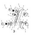
- FIG. 1illustrates a side perspective view of a transconnector in accordance with a first preferred embodiment of the present invention
- FIG. 2illustrates a top perspective view of the transconnector of FIG. 1 ;
- FIG. 3illustrates a side elevational view of the transconnector of FIG. 1 , shown in a collapsed position
- FIG. 4illustrates a side elevational view of the transconnector of FIG. 1 , shown in a partially expanded position
- FIG. 5illustrates a top perspective, exploded view of the transconnector of FIG. 1 ;
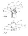
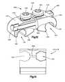
- FIG. 6Aillustrates a top plan view of an articulating spinal rod engaging member of the transconnector of FIG. 1 , wherein the articulating spinal rod engaging member is pivoted in the yaw direction and is engaged with a spinal rod;
- FIG. 6Billustrates a front elevational view of the articulating spinal rod engaging member of the transconnector of FIG. 1 , wherein the articulating spinal rod engaging member is pivoted in the roll direction and is engaged with the spinal rod;
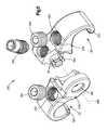
- FIG. 7illustrates a front perspective, exploded view of a transconnector in accordance with a second preferred embodiment of the present invention
- FIG. 8illustrates a cross-sectional view of the transconnector of FIG. 7 , taken along line 8 - 8 of FIG. 7 ;
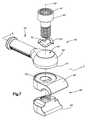
- FIG. 9Aillustrates a top perspective view of a coupler or transconnector mounted to spinal rods in accordance with a third preferred embodiment of the present invention.
- FIG. 9Billustrates an exploded view of the coupler of FIG. 9A ;
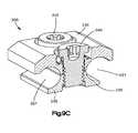
- FIG. 9Cillustrates a cross-section view of the coupler of FIG. 9A , taken along line 9 C- 9 C of FIG. 9A ;
- FIG. 10illustrates a top perspective view of a transconnector in accordance with a fourth preferred embodiment of the present invention, shown in an expanded position;
- FIG. 10Aillustrates a top perspective view of the transconnector of FIG. 10 , shown in a partially collapsed position
- FIG. 11illustrates an exploded view of the transconnector of FIG. 10 ;
- FIG. 12illustrates a side perspective view of a transconnector in accordance with a fifth preferred embodiment of the present invention.
- FIG. 13illustrates a front elevational view of a bridge member used in connection with the transconnector of FIG. 12 .
- transconnectors 10 , 10 ′, 200 , 300 , 400(collectively referred to herein as a transconnector), by way of non-limiting example, the transconnectors 10 , 10 ′, 200 , 300 , 400 are preferably used for interconnecting a pair of longitudinal spinal rods in a posterior spinal fixation procedure.
- the transconnectors 10 , 10 ′, 200 , 300 , 400may have other applications and uses and should not be limited to the structure or use described and illustrated.
- the transconnectors 10 , 10 ′, 200 , 300 , 400may be configured to engage only one spinal rod 5 , while another end of the transconnectors 10 , 10 ′, 200 , 300 , 400 is configured to directly engage a patient's vertebra via, for example, a bone screw.
- the transconnectors 10 , 10 ′, 200 , 300 , 400may be configured to provide multiple degrees of freedom to permit the transconnectors 10 , 10 ′, 200 , 300 , 400 to accommodate varying alignments of spinal rods 5 .
- the transconnectors 10 , 10 ′, 200 , 300 , 400may be configured to angulate and translate with respect to the longitudinal spinal rods 5 after being initially coupled at one end to the spinal rod 5 , thus permitting the transconnectors 10 , 10 ′, 200 , 300 , 400 to accommodate, for example, converging and/or diverging longitudinal spinal rods 5 , non-coplanar longitudinal spinal rods 5 , and longitudinal spinal rods 5 that have varying rod separation distances.
- transconnectors 10 , 10 ′, 200 , 300 , 400are described as and may generally be used in the spine (for example, in the lumbar, thoracic or cervical regions), those skilled in the art will appreciate that the transconnectors 10 , 10 ′, 200 , 300 , 400 may be used for fixation of other parts of the body such as, for example, joints, long bones or bones in the hand, face, feet, etc.
- the transconnectors 10 , 10 ′, 200 , 300 , 400may be used for external fixation of the body such as, for example, where rods are joined outside of the patient's body to, for example, the patient's vertebra, long bones, etc.
- the preferred transconnectors 10 , 10 ′, 200 , 300 , 400may be constructed from any biocompatible material including, but not limited to, stainless steel, titanium, titanium alloys, polymers, memory shaped alloys, etc. that is able to take on the general shape of the transconnectors 10 , 10 ′, 200 , 300 , 400 and withstand the normal operating conditions of the transconnectors 10 , 10 ′, 200 , 300 , 400 .
- the longitudinal spinal rod 5may include, but not be limited to, a solid rod, a non-solid rod, a flexible or dynamic rod, etc. Alternatively, the longitudinal spinal rod 5 may not be a rod at all and may be in the shape of, for example, a plate. It should be understood that the transconnectors 10 , 10 ′, 200 , 300 , 400 are not limited for use in combination with or as an assembly with any particular type of longitudinal spinal rod 5 .
- the transconnector 10may include a pair of spinal rod engaging members 20 and a bridge member 75 .
- the bridge member 75preferably includes a first member 76 and a second member 78 wherein the first and second members 76 , 78 are moveable displaceable with respect to one another so that the length of the transconnector 10 can be adjusted to vary the distance between the spinal rod engaging members 20 so that the transconnector 10 can accommodate various distances between longitudinal spinal rods 5 .
- the transconnector 10is able to allow for varied medial to lateral adjustment.
- the bridge member 75may be in the form of a single, nonadjustable fixed length member.
- the first and second members 76 , 78 of the bridge member 75are slidably mounted to each other for movement between a collapsed position ( FIG.
- first and second members 76 , 78are not limited to being slidably mounted together and may be alternatively mounted relative to each other to permit modification of the distance and/or orientation of the engaging members 20 relative to each other.
- the first and second members 76 , 78may take on any number of forms, including but not limited to, for example, outer and inner telescopic rods wherein the inner rod is telescopically received within the outer telescopic rod.
- the first and second members 76 , 78may be in the form of lateral side by side members that slide relative to one another to provide an adjustable length bridge member 75 .
- Other arrangements of first and second members 76 , 78are also envisioned to construct an adjustable length bridge member 75 .
- first and second members 76 , 78 of the adjustable length bridge member 75preferably are in the form of a T-beam 80 and a C-channel 82 , respectively, wherein at least a portion of the T-beam 80 is slidably received within the C-channel 82 .
- This configurationenables the T-beam 80 and C-channel 82 to move laterally with respect to one another while substantially preventing twisting and/or rotation.
- the first and second members 76 , 78may take on other complementary shapes that enable lateral movement while in the first preferred embodiment, preferably, substantially preventing twisting and/or rotation.
- the adjustable length bridge member 75may enable adjustment from about 30 mm to about 90 mm between spinal rod centers.
- the adjustable length bridge member 75also preferably includes a mechanism for fixing the position of the first and second members 76 , 78 with respect to one another.
- the mechanismmay be any mechanism now or hereafter known including, but not limited to, for example, a bolt, ratchet, clamp, etc.
- the adjustable length bridge member 75preferably includes a translation screw 85 for generating the necessary clamping force to secure the position of the first and second members 76 , 78 with respect to one another.
- the translation screw 85preferably is configured so that the first and second members 76 , 78 are prevented from coming apart or separating.
- the translation screw 85is preferably “staked” so that the translation screw 85 can not be removed from the first and second member 76 , 78 and hence the first and second members 76 , 78 are prohibited from separating.
- the first and second members 76 , 78are preferably provided with a radius to permit the transconnector 10 to span over parts of the human anatomy such as, for example, the patient's dura, facets, lamina, spinous process, etc.
- the first and second members 76 , 78have a radius of about 60 mm. Although it is envisioned that other radiuses may be used. Alternatively, the first and second members 76 , 78 may be straight.
- the transconnector 10includes the pair of spinal rod engaging members 20 operatively coupled to the first and second members 76 , 78 that each include a rod receiving channel 21 for receiving one of the longitudinal spinal rods 5 therein.
- the transconnector 10may include a pair of articulating spinal rod engaging members 22 operatively coupled to the first and second members 76 , 78 , respectively, a pair of non-articulating spinal rod engaging members 24 operatively coupled to the first and second members 76 , 78 , respectively, or any combination thereof. For example, as best shown in FIG.
- one of the first and second members 76 , 78may include a non-articulating spinal rod engaging member 24 while the other of the first and second members 76 , 78 may include an articulating spinal rod engaging member 22 .
- incorporation of the articulating spinal rod engaging member 22enables the spinal rod engaging member 20 to articulate with respect to the bridge member 75 thus enabling the spinal rod engaging member 20 to engage a pair of spinal rods 5 that are generally oriented in a non-parallel manner.
- the articulating spinal rod engaging member 22enables about plus or minus twenty-two degrees (+/ ⁇ 22°) of articulation in the yaw direction (for a total of forty-four degrees (44°) of motion), as best shown in FIG.
- the articulating spinal rod engaging members 22may include an upper clamp body 30 , a lower clamp body 35 , a compression cap 45 and an actuation screw 40 .
- at least one of the upper clamp bodies 30is moveably connected to the bridge member 75 by, for example, a recess 31 formed in the upper clamp body 30 , wherein the recess 31 has an inner curvate or spherical surface 32 for engaging an outer curvate or spherical surface 77 formed on at least one end of the bridge member 75 so that the upper clamp body 30 may be connected to the bridge member 75 via a curvate or spherical connecting surface.
- the compression cap 45preferably includes an internal curvate or spherical shape 46 for mating with the outer curvate or spherical surface 77 formed on the bridge member 75 .
- the lower clamp body 35is preferably moveably connected to the upper clamp body 30 by, for example, the actuation screw 40 .
- the bridge member 75 , the upper clamp body 30 , the lower clamp body 35 and the compression cap 45preferably all include an internal bore 43 for receiving the actuation screw 40 .
- the upper clamp body 30 , the lower clamp body 35 , the bridge member 75 and the compression cap 45all include a bore 43 for receiving the actuation screw 40 such that the actuation screw 40 passes through the compression cap 45 , the upper clamp body 30 , the bridge member 75 and into threaded engagement with the lower clamp body 35 such that rotation of the actuation screw 40 moves the lower clamp body 35 with respect to the upper clamp body 30 to thereby secure the rod 5 within the rod receiving channel 21 and compresses the internal curvate or spherical surface 46 formed in the compression cap 45 against the outer curvate or spherical surface 77 formed on the bridge member 75 to fix the position of the articulating spinal rod engaging members 22 with respect to the bridge member 75 .
- rotation of the actuation screw 40preferably causes the lower clamp body 35 to move towards the upper clamp body 30 to thereby secure the position of the spinal rod 5 with respect to the spinal rod engaging member 20 when the spinal rod engaging member 22 is engaged with the spinal rod 5 .
- rotation of the actuation screw 40also secures the position of the upper and lower clamp bodies 30 , 35 with respect to the bridge member 75 (e.g., to secure the roll and yaw position of articulating spinal rod engaging members 22 with respect to the bridge member 75 ).
- the spinal rod engaging members 20 and hence the transconnector 10requires less spinal rod clearance on the anterior side of the spinal rod 5 in order to attach the spinal rod engaging members 20 to the longitudinal spinal rods 5 , thereby helping the transconnector 10 to achieve a lower profile.
- the bridge member 75may include an integrally formed lower clamp body (not shown).
- the actuation screws 40preferably include a mechanism for preventing the actuation screws 40 from becoming separated from the transconnector 10 .
- the actuation screws 40may include “staked” ends so that the actuation screws 40 are difficult to remove from the spinal rod engaging members 20 and hence the spinal rod engaging members 20 are difficult to separate from the bridge member 75 .
- the upper and lower clamp bodies 30 , 35preferably define the rod receiving channel 21 for receiving the longitudinal spinal rod 5 .
- the rod receiving channel 21may include a roughened or textured surface, for example, a glass beaded texture, radial teeth, serrations, grooves, etc. for contacting the outer surface of the longitudinal spinal rod 5 in order to limit rotational or axial slippage of the rod 5 with respect to the spinal rod engaging members 20 .
- the spinal rod engaging members 20preferably also include a spring 50 .
- the spring 50may take on any number of forms now or hereafter known including, for example, a helical spring, leaf spring, compression spring, flexible block, etc.
- the spring 50is in the form of a spring washer.
- the spring 50preferably provides an opposing force to permit the spinal rod engaging members 20 to provisionally “snap” onto or otherwise provisionally engage the longitudinal spinal rods 5 . That is, the spring 50 preferably includes a bore 52 for receiving the actuation screw 40 therethrough.
- the spring 50is preferably located between the head 41 of the actuation screw 40 and the compression cap 45 or the integral upper clamp body 30 so that the spring 50 provides a bias force which causes the lower clamp body 35 to press against the upper clamp body 30 so that the longitudinal spinal rod 5 may be provisionally or tentatively received and held within the rod receiving channels 21 formed in the spinal rod engaging members 20 .
- the spring 50biases the lower clamp body 35 toward or into engagement with the upper clamp body 30 by applying a bias force to the underside of the head of the actuation screw 40 , which biases the lower clamp body 35 toward the upper clamp body 30 through engagement of the threads on the actuation screw 40 and the threads in the bore 43 of the lower clamp body 30 .
- the spring 50biases the lower clamp body 35 toward the upper clamp body 30 to define a relatively small diameter rod receiving channel 21 in the first preferred embodiment, but also permits the lower clamp body 35 to be urged away from the upper clamp body 30 by compressing the spring 50 , thereby enlarging the rod receiving channel 21 such that the rod 5 may be received therein.
- one or both of the spinal rod engaging members 20may be configured as a non-articulating spinal rod engaging member 24 .
- a non-articulating spinal rod engaging member 24is substantially identical to an articulating spinal rod engaging member 22 described above, however, in the non-articulating spinal rod engaging member 24 , the upper clamp body 30 may be integrally formed with the bridge member 75 (shown as integrally formed with the second member 78 of the bridge member 75 ). Alternatively, it is envisioned that the upper clamp body 30 may be a separate and distinct member from the bridge member 75 and affixed thereto by any means now or hereafter known, such as welding, adhesive bonding, clamping, fastening, etc.
- rotation of the actuation screw 40preferably secures the position of the upper and lower clamp bodies 30 , 35 with respect to the bridge member 75 (e.g., fixes the articulated position (i.e., yaw and roll positions) of the articulated spinal rod engaging member 22 with respect to the bridge member 75 ) and provides clamping force to secure the spinal rod 5 in the rod-receiving channel 21 of the articulated spinal rod engaging member 22 .
- rotation of the actuation screw 40preferably only provides the necessary clamping force to secure the spinal rod 5 in the rod receiving channel 21 of the spinal rod engaging member 24 .
- the bridge member 75 ′may be in the form of first and second telescopic, tubular members (only one of which is shown) wherein the first member is sized and configured to be received within the second member.
- the transconnector 10 ′may only include one spinal rod engaging member 20 ′ for directly engaging only one spinal rod 5 , while the other end of the transconnector 10 ′ is configured to directly engage a patient's vertebra via, for example, a bone screw.
- the spinal rod engaging members 20 ′may be located in a stacked relationship relative to the bridge member 75 ′. That is, for example, the bridge member 75 ′ may be located on top of or to one side of the upper and lower clamp bodies 30 ′, 35 ′.
- the bridge member 75 ′may include an enlarged diametric end 90 ′ having the bore 43 ′ for receiving the actuation screw 40 ′.
- the upper and lower clamp bodies 30 ′, 35 ′are preferably moveably coupled to the bridge member 75 ′ so that the spinal rod engaging members 20 ′ is preferably, pivotally associated with the bridge member 75 ′ about the longitudinal axis 42 ′ of the actuation screw 40 ′ to better accommodate non-parallel and/or converging/diverging rods 5 .
- the bottom surface 91 ′ of the enlarged diametric end 90 ′may be configured to contact the top surface 32 ′ of the upper clamp body 30 ′.
- the bottom surface 91 ′ of the enlarged diametric ends 90 ′ and the top surface 32 ′ of the upper clamp body 30 ′may include corresponding serrations in order to provide better securement.
- the bottom surface 91 ′ of the enlarged diametric ends 90 ′ and the top surface 32 ′ of the upper clamp body 30 ′may be bead blasted (e.g., roughened surface) in order to provide potentially improved securement.
- the spinal rod engaging members 20 ′preferably also include a spring 50 ′ to provide an opposing force in order to permit the longitudinal spinal rods 5 to provisionally snap into the rod receiving channels 21 ′ formed in the spinal rod engaging members 20 ′.
- the spring 50 ′preferably includes a bore 52 ′ for receiving the actuation screw 40 ′ therethrough.
- the spring 50 ′is preferably located between the head 41 ′ of the actuation screw 40 ′ and the bridge member 75 ′, as best shown in FIG. 7 , so that the spring 50 ′ provides an initial force which causes the lower clamp body 35 ′ to press against the upper clamp body 30 ′ so that the longitudinal spinal rod 5 may be tentatively or provisionally received and held within the rod receiving channel 21 ′.
- the spring 50 ′may take on any number of forms now or hereafter known including, but not limited to, a spring washer.
- the spring 50 ′preferably provides an opposing force in order to permit the spinal rod engaging members 20 ′ to provisionally snap onto the longitudinal spinal rods 5 .
- the operation of the transconnector 10 ′is substantially similar to the operation of the transconnector 10 discussed above.
- a coupler or transconnector 200 in accordance with a third preferred embodiment for interconnecting substantially parallel rods 205is disclosed.
- the coupler 200may be used as a transconnector to couple substantially parallel transverse spinal rods 5 .
- the coupler 200may be used to couple substantially parallel longitudinal spinal rods 5 .
- the coupler 200may be used in other parts of the body to couple substantially parallel rods including, but not limited to, internal or external fixation of long bones.
- the coupler 200preferably includes an upper clamp body 230 , a lower clamp body 235 , one or more actuation screws 240 , and one or more springs 250 .
- the operation of the coupler 200is substantially identical to the operation of the transconnectors 10 , 10 ′ discussed above. That is, the lower clamp body 235 is preferably moveably connected to the upper clamp body 230 by, for example, the actuation screw 240 .
- the upper clamp body 230 and the lower clamp body 235include an internal bore 243 that receives the actuation screw 240 .
- the upper and lower clamp bodies 230 , 235define a rod receiving channel 221 for receiving the longitudinal spinal rods 205 .
- rotation of the actuation screw 240causes the lower clamp body 235 to move towards the upper clamp body 230 to thereby secure the position of the spinal rods 205 with respect to the coupler 200 , when the spinal rods 205 are positioned in the rod receiving channel 221 .
- the spring 250preferably provides an opposing force in order to permit the longitudinal spinal rods 205 provisionally snap into the rod receiving channels 221 formed in the coupler 200 .
- the spring 250is preferably in the form of a spring washer having a bore 252 for receiving the actuation screw 240 therethrough.
- the spring 250is preferably located between the head 241 of the actuation screw 240 and the upper clamp body 230 so that the spring 250 provides an initial force which causes the lower clamp body 235 to press against the upper clamp body 230 so that the longitudinal spinal rod 205 may be tentatively received and held within the rod receiving channel 221 formed in the coupler 200 .
- the spring 250may taken on any one of a number of different forms, as was described above.
- FIGS. 10-11A fourth preferred embodiment of a transconnector 300 is shown in FIGS. 10-11 .
- the bridge member 375may be in the form of first and second members 376 , 378 wherein the first member 376 is pivotally coupled or hinged to the second member 378 .
- the first member 376is preferably pivotally coupled or hinged to the second member 378 via a pivot axis 386 that may be substantially transverse to a longitudinal axis 388 of the transconnector 300 , which is defined in an expanded position, so that pivotal adjustment of the first and second members 376 , 378 causes the bridge member 375 to bend in the anatomical axial plane.
- pivotable adjustment of the first member 376 with respect to the second member 378preferably alters the length of the transconnector 300 or a distance between spinal rod engaging members 320 at either end of the transconnector 300 .
- Pivotal adjustment of the first member 376 with respect to the second member 378may cause the bridge member 375 to move posteriorly thus shortening the overall length of the transconnector 300 , as best shown in FIG. 10A .
- the first and second members 376 , 378may be coupled to one another by any means now or hereafter known that permits the first and second members 376 , 378 to pivot with respect to one another.
- the second member 378includes a hole 392 formed therein, wherein the hole 392 receives a projection 390 laterally extending from the first member 376 .
- the projection 390preferably includes a plurality of tabs 391 .
- the bridge member 375preferably also includes a threaded fastener or set screw 394 .
- the set screw 394is threadably engageable with the first member 376 such that rotation of the set screw 394 causes the projection 390 , more preferably the plurality of tabs 391 to expand, thereby causing the tabs 391 to exert a force onto the inner surface of the hole 392 to thereby secure the position of the first member 376 with respect to the second member 378 .
- the first and second members 376 , 378preferably include integral spinal rod engaging members 320 , but are not so limited.
- the spinal rod engaging members 320include a rod receiving channel 321 that receives a longitudinal spinal rod 5 .
- the spinal rod engaging members 320also include a throughbore 322 that receives a wedge member 324 (e.g. set screw) for securing the spinal rod 5 in the rod receiving channel 321 of the spinal rod engaging member 320 .
- the transconnector 300may include non-integral spinal rod engaging members 320 .
- FIGS. 12 and 13A fifth preferred embodiment of a transconnector 400 is shown in FIGS. 12 and 13 .
- the bridge member 475may be in the form of first and second members 476 , 478 , wherein the first member 476 and the second member 478 are laterally adjustable with respect to one another.
- the first and second members 476 , 478may take on any number of forms, preferably, as shown, the first and second members 476 , 478 are each in the form of a non-articulating spinal rod engaging member 420 including a post 460 extending therefrom.
- the spinal rod engaging members 420further include a throughbore 462 passing therethrough, wherein the throughbore 462 receives the post 460 extending from the other spinal rod engaging member 420 .
- the spinal rod engaging members 420preferably include a separate, non-integral lower clamp body 435 that is moveably connected to the upper clamp body 430 by, for example, an actuation screw 440 , as previously described.
- rotation of the actuation screw 440preferably secures (i) the position of the lower clamp body 435 with respect to the upper clamp body 430 and hence fixes the position of the longitudinal spinal rod 5 within the rod receiving channel 421 and (ii) the position of the second member 478 with respect to the first member 476 .
- the first and second members 476 , 478preferably include a slot 464 formed therein so that rotation of the actuation screw 440 causes the spinal rod engaging members 420 to compress against the post 460 of the alternate spinal rod engaging member 420 thereby fixing the position of the first member 476 with respect to the second member 478 .
- the upper and lower clamp bodies 430 , 435preferably include a rod receiving channel 421 formed therein for receiving the longitudinal spinal rod 5 .
- the rod receiving channel 421may include a roughened or textured surface, for example, a glass beaded texture, radial teeth, serrations, grooves, etc. for contacting the outer surface of the longitudinal spinal rod 5 in order to prevent rotational or axial slippage of the rod 5 with respect to the spinal rod engaging members 420 .
- the upper and lower clamp bodies 430 , 435 of the spinal rod engaging members 420preferably each include a spring 450 to provide an opposing force in order to permit the spinal rod engaging members 420 to provisionally snap onto the longitudinal spinal rods 5 .
- the first and second members 476 , 478preferably also include a feature for preventing the first and second members 476 , 478 from separating.
- the posts 460may include enlarged ends that limit the first and second members 476 , 478 from pulling apart with respect to one another.
Landscapes
- Health & Medical Sciences (AREA)
- Orthopedic Medicine & Surgery (AREA)
- Life Sciences & Earth Sciences (AREA)
- Surgery (AREA)
- Neurology (AREA)
- Molecular Biology (AREA)
- Veterinary Medicine (AREA)
- Biomedical Technology (AREA)
- Heart & Thoracic Surgery (AREA)
- Medical Informatics (AREA)
- Nuclear Medicine, Radiotherapy & Molecular Imaging (AREA)
- Animal Behavior & Ethology (AREA)
- General Health & Medical Sciences (AREA)
- Public Health (AREA)
- Engineering & Computer Science (AREA)
- Surgical Instruments (AREA)
- Prostheses (AREA)
- Photoreceptors In Electrophotography (AREA)
- Discharging, Photosensitive Material Shape In Electrophotography (AREA)
- Feeding And Controlling Fuel (AREA)
- Lasers (AREA)
- Mechanical Coupling Of Light Guides (AREA)
Abstract
Description
Claims (45)
Priority Applications (3)
| Application Number | Priority Date | Filing Date | Title |
|---|---|---|---|
| US13/418,912US8454661B2 (en) | 2007-09-25 | 2012-03-13 | Transconnector |
| US13/896,864US9510870B2 (en) | 2007-09-25 | 2013-05-17 | Transconnector |
| US15/344,952US9949768B2 (en) | 2007-09-25 | 2016-11-07 | Transconnector |
Applications Claiming Priority (4)
| Application Number | Priority Date | Filing Date | Title |
|---|---|---|---|
| US97507107P | 2007-09-25 | 2007-09-25 | |
| PCT/US2008/077471WO2009042653A1 (en) | 2007-09-25 | 2008-09-24 | Transconnector |
| US68008910A | 2010-03-25 | 2010-03-25 | |
| US13/418,912US8454661B2 (en) | 2007-09-25 | 2012-03-13 | Transconnector |
Related Parent Applications (3)
| Application Number | Title | Priority Date | Filing Date |
|---|---|---|---|
| US12/680,089ContinuationUS8262701B2 (en) | 2007-09-25 | 2008-09-24 | Transconnector |
| PCT/US2008/077471ContinuationWO2009042653A1 (en) | 2007-09-25 | 2008-09-24 | Transconnector |
| US68008910AContinuation | 2007-09-25 | 2010-03-25 |
Related Child Applications (1)
| Application Number | Title | Priority Date | Filing Date |
|---|---|---|---|
| US13/896,864ContinuationUS9510870B2 (en) | 2007-09-25 | 2013-05-17 | Transconnector |
Publications (2)
| Publication Number | Publication Date |
|---|---|
| US20120179204A1 US20120179204A1 (en) | 2012-07-12 |
| US8454661B2true US8454661B2 (en) | 2013-06-04 |
Family
ID=40040080
Family Applications (4)
| Application Number | Title | Priority Date | Filing Date |
|---|---|---|---|
| US12/680,089Active2029-04-15US8262701B2 (en) | 2007-09-25 | 2008-09-24 | Transconnector |
| US13/418,912ActiveUS8454661B2 (en) | 2007-09-25 | 2012-03-13 | Transconnector |
| US13/896,864Active2029-04-30US9510870B2 (en) | 2007-09-25 | 2013-05-17 | Transconnector |
| US15/344,952ActiveUS9949768B2 (en) | 2007-09-25 | 2016-11-07 | Transconnector |
Family Applications Before (1)
| Application Number | Title | Priority Date | Filing Date |
|---|---|---|---|
| US12/680,089Active2029-04-15US8262701B2 (en) | 2007-09-25 | 2008-09-24 | Transconnector |
Family Applications After (2)
| Application Number | Title | Priority Date | Filing Date |
|---|---|---|---|
| US13/896,864Active2029-04-30US9510870B2 (en) | 2007-09-25 | 2013-05-17 | Transconnector |
| US15/344,952ActiveUS9949768B2 (en) | 2007-09-25 | 2016-11-07 | Transconnector |
Country Status (14)
| Country | Link |
|---|---|
| US (4) | US8262701B2 (en) |
| EP (1) | EP2190368B1 (en) |
| JP (1) | JP5466160B2 (en) |
| KR (1) | KR101567593B1 (en) |
| CN (1) | CN101873835B (en) |
| AT (1) | ATE499059T1 (en) |
| AU (1) | AU2008304546A1 (en) |
| BR (1) | BRPI0817238A2 (en) |
| CA (1) | CA2698970A1 (en) |
| CO (1) | CO6260038A2 (en) |
| DE (1) | DE602008005162D1 (en) |
| ES (1) | ES2359604T3 (en) |
| PL (1) | PL2190368T3 (en) |
| WO (1) | WO2009042653A1 (en) |
Cited By (17)
| Publication number | Priority date | Publication date | Assignee | Title |
|---|---|---|---|---|
| US20140358181A1 (en)* | 2007-01-29 | 2014-12-04 | Samy Abdou | Spinal stabilization systems and methods of use |
| US8940020B2 (en) | 2012-04-06 | 2015-01-27 | DePuy Synthes Products, LLC | Rod connector |
| US10363073B2 (en) | 2016-07-13 | 2019-07-30 | Medos International Sàrl | Bone anchor assemblies and related instrumentation |
| US10413331B2 (en) | 2016-12-21 | 2019-09-17 | Spine Wave, Inc. | Spinal stabilization system with head to head cross connector |
| US10463402B2 (en) | 2016-07-13 | 2019-11-05 | Medos International Sàrl | Bone anchor assemblies and related instrumentation |
| US10543107B2 (en) | 2009-12-07 | 2020-01-28 | Samy Abdou | Devices and methods for minimally invasive spinal stabilization and instrumentation |
| US10548740B1 (en) | 2016-10-25 | 2020-02-04 | Samy Abdou | Devices and methods for vertebral bone realignment |
| US10568667B2 (en) | 2016-07-13 | 2020-02-25 | Medos International Sàrl | Bone anchor assemblies and related instrumentation |
| US10575961B1 (en) | 2011-09-23 | 2020-03-03 | Samy Abdou | Spinal fixation devices and methods of use |
| US10695105B2 (en) | 2012-08-28 | 2020-06-30 | Samy Abdou | Spinal fixation devices and methods of use |
| US10857003B1 (en) | 2015-10-14 | 2020-12-08 | Samy Abdou | Devices and methods for vertebral stabilization |
| US10874438B2 (en) | 2016-07-13 | 2020-12-29 | Medos International Sarl | Bone anchor assemblies and related instrumentation |
| US10918498B2 (en) | 2004-11-24 | 2021-02-16 | Samy Abdou | Devices and methods for inter-vertebral orthopedic device placement |
| US10973648B1 (en) | 2016-10-25 | 2021-04-13 | Samy Abdou | Devices and methods for vertebral bone realignment |
| US11006982B2 (en) | 2012-02-22 | 2021-05-18 | Samy Abdou | Spinous process fixation devices and methods of use |
| US11173040B2 (en) | 2012-10-22 | 2021-11-16 | Cogent Spine, LLC | Devices and methods for spinal stabilization and instrumentation |
| US11179248B2 (en) | 2018-10-02 | 2021-11-23 | Samy Abdou | Devices and methods for spinal implantation |
Families Citing this family (54)
| Publication number | Priority date | Publication date | Assignee | Title |
|---|---|---|---|---|
| US7744635B2 (en)* | 2004-06-09 | 2010-06-29 | Spinal Generations, Llc | Spinal fixation system |
| EP1971282A2 (en) | 2006-01-10 | 2008-09-24 | Life Spine, Inc. | Pedicle screw constructs and spinal rod attachment assemblies |
| US8603141B2 (en)* | 2007-09-19 | 2013-12-10 | Pioneer Surgical Technology, Inc. | Intervertebral implant devices and methods for insertion thereof |
| US8292924B2 (en)* | 2007-10-05 | 2012-10-23 | Spineworks, Llc | Enhanced pedicle rod clamp device |
| US9060813B1 (en) | 2008-02-29 | 2015-06-23 | Nuvasive, Inc. | Surgical fixation system and related methods |
| EP2421454A4 (en)* | 2009-04-23 | 2013-12-11 | Spinal Elements Inc | Transverse connectors |
| US8246657B1 (en) | 2009-06-29 | 2012-08-21 | Nuvasive, Inc. | Spinal cross connector |
| US8568456B2 (en)* | 2009-09-21 | 2013-10-29 | Globus Medical, Inc. | Transverse connector having a locking element for capturing multiple rods |
| WO2011069963A2 (en)* | 2009-12-10 | 2011-06-16 | Kilian Kraus | Rod connector |
| US9198696B1 (en) | 2010-05-27 | 2015-12-01 | Nuvasive, Inc. | Cross-connector and related methods |
| US20120271353A1 (en)* | 2010-08-16 | 2012-10-25 | Mark Barry | System and method for aligning vertebrae in the amelioration of aberrant spinal column deviation conditions in patients requiring the accomodation of spinal column growth or elongation |
| US9504495B2 (en) | 2011-02-11 | 2016-11-29 | Blackstone Medical, Inc. | Multi-axial pedicle fixation assembly and method for use |
| US9387013B1 (en) | 2011-03-01 | 2016-07-12 | Nuvasive, Inc. | Posterior cervical fixation system |
| US9247964B1 (en) | 2011-03-01 | 2016-02-02 | Nuasive, Inc. | Spinal Cross-connector |
| CA2831081A1 (en) | 2011-04-07 | 2012-10-11 | Mike Hammer | Clamp for spinal cross connecting device |
| JP6106662B2 (en)* | 2011-05-17 | 2017-04-05 | ジンマー,インコーポレイティド | External fixed clamping system using a starting mechanism and stored spring energy |
| US9005249B2 (en) | 2011-07-11 | 2015-04-14 | Life Spine, Inc. | Spinal rod connector assembly |
| US9339305B2 (en) | 2011-09-19 | 2016-05-17 | DePuy Synthes Products, Inc. | Snap fit rod and fastener system |
| US8758411B1 (en) | 2011-10-25 | 2014-06-24 | Nuvasive, Inc. | Implants and methods for treating spinal disorders |
| US8740950B2 (en) | 2011-12-08 | 2014-06-03 | Spine Wave, Inc. | Methods for percutaneously attaching a cross connector to contralateral spinal constructs |
| US9125691B2 (en)* | 2011-12-23 | 2015-09-08 | Amendia, Inc. | Transverse crosslink device |
| US8945186B2 (en)* | 2011-12-30 | 2015-02-03 | Blackstone Medical, Inc. | Multi-axial spinal cross connecting device |
| US8556942B2 (en) | 2011-12-30 | 2013-10-15 | Blackstone Medical, Inc. | Occipito-cervical fixation assembly and method for constructing same |
| KR101325746B1 (en) | 2012-01-16 | 2013-11-08 | 주식회사 만도 | Combining structure of shock absorber |
| US9055982B2 (en)* | 2012-09-25 | 2015-06-16 | Warsaw Orthopedic, Inc. | Spinal implant system and methods of use |
| US9936982B2 (en) | 2012-11-26 | 2018-04-10 | Spinefrontier, Inc | System and method for translateral linking of bilateral spinal fixation rods |
| JP5998890B2 (en)* | 2012-12-06 | 2016-09-28 | 富士通株式会社 | Spring washers and fixtures |
| WO2014172445A1 (en) | 2013-04-17 | 2014-10-23 | Ebi, Llc | Cross connector system |
| US20150073488A1 (en)* | 2013-09-09 | 2015-03-12 | James A. Rinner | Spinal stabilization system |
| US9681903B2 (en)* | 2013-11-15 | 2017-06-20 | K2M, Inc. | Clip for dynamic spinal plate |
| CN104287818B (en)* | 2014-10-29 | 2017-04-19 | 刘忠军 | Length-adjustable vertebral plate |
| WO2016107585A1 (en)* | 2014-12-30 | 2016-07-07 | 苏州天臣国际医疗科技有限公司 | Nail head assembly and suturing and cutting apparatus for endoscopic surgery |
| US10321939B2 (en)* | 2016-05-18 | 2019-06-18 | Medos International Sarl | Implant connectors and related methods |
| US10517647B2 (en) | 2016-05-18 | 2019-12-31 | Medos International Sarl | Implant connectors and related methods |
| KR101910597B1 (en)* | 2016-12-02 | 2018-10-22 | 안경기 | Rod connector |
| US10398476B2 (en) | 2016-12-13 | 2019-09-03 | Medos International Sàrl | Implant adapters and related methods |
| US10492835B2 (en) | 2016-12-19 | 2019-12-03 | Medos International Sàrl | Offset rods, offset rod connectors, and related methods |
| CN106510823A (en)* | 2016-12-28 | 2017-03-22 | 上海凯利泰医疗科技股份有限公司 | Universal transverse connector |
| US10238432B2 (en) | 2017-02-10 | 2019-03-26 | Medos International Sàrl | Tandem rod connectors and related methods |
| US10966761B2 (en)* | 2017-03-28 | 2021-04-06 | Medos International Sarl | Articulating implant connectors and related methods |
| US10561454B2 (en) | 2017-03-28 | 2020-02-18 | Medos International Sarl | Articulating implant connectors and related methods |
| WO2019051260A1 (en) | 2017-09-08 | 2019-03-14 | Pioneer Surgical Technology, Inc. | Intervertebral implants, instruments, and methods |
| USD907771S1 (en) | 2017-10-09 | 2021-01-12 | Pioneer Surgical Technology, Inc. | Intervertebral implant |
| US11076890B2 (en) | 2017-12-01 | 2021-08-03 | Medos International Sàrl | Rod-to-rod connectors having robust rod closure mechanisms and related methods |
| CN113164193A (en)* | 2018-12-14 | 2021-07-23 | 捷迈拜欧米特Cmf和胸腔有限公司 | Bone fixation and repair system |
| US11612418B2 (en) | 2019-12-13 | 2023-03-28 | Globus Medical, Inc. | Revision connectors, systems, and methods thereof |
| CN111759437A (en)* | 2020-07-28 | 2020-10-13 | 苏州优贝特医疗器械有限公司 | A card slot adjustable universal cross connector |
| US12213706B2 (en) | 2020-10-07 | 2025-02-04 | Globus Medical, Inc. | Systems and methods for surgical procedures using band clamp implants and tensioning instruments |
| US11771475B2 (en) | 2020-10-07 | 2023-10-03 | Globus Medical, Inc. | Systems and methods for surgical procedures using band clamp implants and tensioning instruments |
| US11974785B2 (en) | 2020-10-16 | 2024-05-07 | Globus Medical, Inc | Band clamp implants |
| US11426211B2 (en) | 2020-10-28 | 2022-08-30 | Globus Medical, Inc. | Articulating connectors, systems, and methods thereof |
| KR20220059862A (en)* | 2020-11-03 | 2022-05-10 | 주식회사 솔고 바이오메디칼 | Rod connector device for cervical spine |
| US11331125B1 (en) | 2021-10-07 | 2022-05-17 | Ortho Inventions, Llc | Low profile rod-to-rod coupler |
| JP2025529435A (en)* | 2022-09-13 | 2025-09-04 | メドス・インターナショナル・エスエイアールエル | Modular Connector Assembly |
Citations (26)
| Publication number | Priority date | Publication date | Assignee | Title |
|---|---|---|---|---|
| US5624442A (en) | 1990-04-26 | 1997-04-29 | Cross Medical Products, Inc. | Transverse link for use with a spinal implant system |
| US5716355A (en) | 1995-04-10 | 1998-02-10 | Sofamor Danek Group, Inc. | Transverse connection for spinal rods |
| US5752954A (en) | 1994-09-06 | 1998-05-19 | Howmedica International | External fixation device |
| US5947966A (en) | 1995-06-06 | 1999-09-07 | Sdgi Holdings, Inc. | Device for linking adjacent rods in spinal instrumentation |
| US5980523A (en) | 1998-01-08 | 1999-11-09 | Jackson; Roger | Transverse connectors for spinal rods |
| US6015409A (en) | 1994-05-25 | 2000-01-18 | Sdgi Holdings, Inc. | Apparatus and method for spinal fixation and correction of spinal deformities |
| US6022350A (en) | 1996-05-13 | 2000-02-08 | Stryker France S.A. | Bone fixing device, in particular for fixing to the sacrum during osteosynthesis of the backbone |
| US6096039A (en) | 1998-05-13 | 2000-08-01 | Howmedica Gmbh | Means for interconnecting two spaced elongated rods of a human spine implant |
| US6217578B1 (en) | 1999-10-19 | 2001-04-17 | Stryker Spine S.A. | Spinal cross connector |
| US6238396B1 (en) | 1999-10-07 | 2001-05-29 | Blackstone Medical, Inc. | Surgical cross-connecting apparatus and related methods |
| US6261288B1 (en) | 2000-02-08 | 2001-07-17 | Roger P. Jackson | Implant stabilization and locking system |
| US6554831B1 (en) | 2000-09-01 | 2003-04-29 | Hopital Sainte-Justine | Mobile dynamic system for treating spinal disorder |
| US20030114853A1 (en) | 2001-10-12 | 2003-06-19 | Ian Burgess | Polyaxial cross connector |
| US6616668B2 (en) | 2000-06-09 | 2003-09-09 | Cross Medical Products, Inc. | Adjustable transverse connector for use with a spinal implant system |
| US6761721B2 (en) | 2000-01-24 | 2004-07-13 | Depuy Acromed, Inc. | Transverse connector |
| US20040138659A1 (en) | 2003-01-10 | 2004-07-15 | Ed Austin | External fixation apparatus and method |
| US6872208B1 (en) | 2000-10-06 | 2005-03-29 | Spinal Concepts, Inc. | Adjustable transverse connector |
| US20050090821A1 (en) | 2003-10-22 | 2005-04-28 | Gregory Berrevoets | Crosslink for securing spinal rods |
| US6887241B1 (en) | 2000-10-06 | 2005-05-03 | Spinal Concepts, Inc. | Adjustable transverse connector with cam activated engagers |
| US20050113831A1 (en) | 2002-02-11 | 2005-05-26 | Bruno Franck | Connection system between a spinal rod and a transverse bar |
| US20050228377A1 (en)* | 2004-04-07 | 2005-10-13 | Depuy Spine, Inc. | Spinal cross-connectors |
| US7066938B2 (en) | 2002-09-09 | 2006-06-27 | Depuy Spine, Inc. | Snap-on spinal rod connector |
| US20070135817A1 (en) | 2005-12-08 | 2007-06-14 | Ensign Michael D | Percutaneous screw assembly |
| JP2007526007A (en) | 2003-06-27 | 2007-09-13 | デピュイ・スパイン・エスエイアールエル | Multi-axis bone screw |
| US20070219556A1 (en) | 2004-10-20 | 2007-09-20 | Moti Altarac | System and methods for posterior dynamic stabilization of the spine |
| US7481827B2 (en) | 2003-10-09 | 2009-01-27 | Synthes (U.S.A.) | Linking transconnector for coupling spinal rods |
Family Cites Families (8)
| Publication number | Priority date | Publication date | Assignee | Title |
|---|---|---|---|---|
| US5330473A (en)* | 1993-03-04 | 1994-07-19 | Advanced Spine Fixation Systems, Inc. | Branch connector for spinal fixation systems |
| FR2784282B1 (en)* | 1998-10-09 | 2001-03-23 | Dimso Sa | SPINAL OSTEOSYNTHESIS SYSTEM WITH IMPROVED RIGIDITY |
| US6602253B2 (en)* | 2001-02-12 | 2003-08-05 | Marc Richelsoph | Rod to rod connector |
| US7048736B2 (en)* | 2002-05-17 | 2006-05-23 | Sdgi Holdings, Inc. | Device for fixation of spinous processes |
| US7717938B2 (en)* | 2004-08-27 | 2010-05-18 | Depuy Spine, Inc. | Dual rod cross connectors and inserter tools |
| US20060233597A1 (en) | 2005-04-18 | 2006-10-19 | Ensign Micheal D | Cam based rod connection system and method |
| US8226689B2 (en) | 2005-09-23 | 2012-07-24 | Zimmer Spine, Inc. | Apparatus and methods for spinal implant with variable link mechanism |
| WO2008008853A2 (en)* | 2006-07-11 | 2008-01-17 | Pioneer Surgical Technology, Inc. | Transverse connector |
- 2008
- 2008-09-24KRKR1020107005101Apatent/KR101567593B1/ennot_activeExpired - Fee Related
- 2008-09-24PLPL08832995Tpatent/PL2190368T3/enunknown
- 2008-09-24WOPCT/US2008/077471patent/WO2009042653A1/enactiveApplication Filing
- 2008-09-24CNCN2008801174094Apatent/CN101873835B/enactiveActive
- 2008-09-24DEDE602008005162Tpatent/DE602008005162D1/enactiveActive
- 2008-09-24ATAT08832995Tpatent/ATE499059T1/enactive
- 2008-09-24USUS12/680,089patent/US8262701B2/enactiveActive
- 2008-09-24JPJP2010527100Apatent/JP5466160B2/enactiveActive
- 2008-09-24BRBRPI0817238-2Apatent/BRPI0817238A2/enactiveSearch and Examination
- 2008-09-24EPEP08832995Apatent/EP2190368B1/enactiveActive
- 2008-09-24AUAU2008304546Apatent/AU2008304546A1/ennot_activeAbandoned
- 2008-09-24CACA2698970Apatent/CA2698970A1/ennot_activeAbandoned
- 2008-09-24ESES08832995Tpatent/ES2359604T3/enactiveActive
- 2010
- 2010-04-12COCO10041760Apatent/CO6260038A2/enactiveIP Right Grant
- 2012
- 2012-03-13USUS13/418,912patent/US8454661B2/enactiveActive
- 2013
- 2013-05-17USUS13/896,864patent/US9510870B2/enactiveActive
- 2016
- 2016-11-07USUS15/344,952patent/US9949768B2/enactiveActive
Patent Citations (27)
| Publication number | Priority date | Publication date | Assignee | Title |
|---|---|---|---|---|
| US5624442A (en) | 1990-04-26 | 1997-04-29 | Cross Medical Products, Inc. | Transverse link for use with a spinal implant system |
| US6015409A (en) | 1994-05-25 | 2000-01-18 | Sdgi Holdings, Inc. | Apparatus and method for spinal fixation and correction of spinal deformities |
| US6080153A (en) | 1994-09-06 | 2000-06-27 | Howmedica International | External fixation device |
| US5752954A (en) | 1994-09-06 | 1998-05-19 | Howmedica International | External fixation device |
| US5716355A (en) | 1995-04-10 | 1998-02-10 | Sofamor Danek Group, Inc. | Transverse connection for spinal rods |
| US5947966A (en) | 1995-06-06 | 1999-09-07 | Sdgi Holdings, Inc. | Device for linking adjacent rods in spinal instrumentation |
| US6022350A (en) | 1996-05-13 | 2000-02-08 | Stryker France S.A. | Bone fixing device, in particular for fixing to the sacrum during osteosynthesis of the backbone |
| US5980523A (en) | 1998-01-08 | 1999-11-09 | Jackson; Roger | Transverse connectors for spinal rods |
| US6096039A (en) | 1998-05-13 | 2000-08-01 | Howmedica Gmbh | Means for interconnecting two spaced elongated rods of a human spine implant |
| US6238396B1 (en) | 1999-10-07 | 2001-05-29 | Blackstone Medical, Inc. | Surgical cross-connecting apparatus and related methods |
| US6217578B1 (en) | 1999-10-19 | 2001-04-17 | Stryker Spine S.A. | Spinal cross connector |
| US6761721B2 (en) | 2000-01-24 | 2004-07-13 | Depuy Acromed, Inc. | Transverse connector |
| US6261288B1 (en) | 2000-02-08 | 2001-07-17 | Roger P. Jackson | Implant stabilization and locking system |
| US6616668B2 (en) | 2000-06-09 | 2003-09-09 | Cross Medical Products, Inc. | Adjustable transverse connector for use with a spinal implant system |
| US6554831B1 (en) | 2000-09-01 | 2003-04-29 | Hopital Sainte-Justine | Mobile dynamic system for treating spinal disorder |
| US6872208B1 (en) | 2000-10-06 | 2005-03-29 | Spinal Concepts, Inc. | Adjustable transverse connector |
| US6887241B1 (en) | 2000-10-06 | 2005-05-03 | Spinal Concepts, Inc. | Adjustable transverse connector with cam activated engagers |
| US20030114853A1 (en) | 2001-10-12 | 2003-06-19 | Ian Burgess | Polyaxial cross connector |
| US20050113831A1 (en) | 2002-02-11 | 2005-05-26 | Bruno Franck | Connection system between a spinal rod and a transverse bar |
| US7066938B2 (en) | 2002-09-09 | 2006-06-27 | Depuy Spine, Inc. | Snap-on spinal rod connector |
| US20040138659A1 (en) | 2003-01-10 | 2004-07-15 | Ed Austin | External fixation apparatus and method |
| JP2007526007A (en) | 2003-06-27 | 2007-09-13 | デピュイ・スパイン・エスエイアールエル | Multi-axis bone screw |
| US7481827B2 (en) | 2003-10-09 | 2009-01-27 | Synthes (U.S.A.) | Linking transconnector for coupling spinal rods |
| US20050090821A1 (en) | 2003-10-22 | 2005-04-28 | Gregory Berrevoets | Crosslink for securing spinal rods |
| US20050228377A1 (en)* | 2004-04-07 | 2005-10-13 | Depuy Spine, Inc. | Spinal cross-connectors |
| US20070219556A1 (en) | 2004-10-20 | 2007-09-20 | Moti Altarac | System and methods for posterior dynamic stabilization of the spine |
| US20070135817A1 (en) | 2005-12-08 | 2007-06-14 | Ensign Michael D | Percutaneous screw assembly |
Cited By (37)
| Publication number | Priority date | Publication date | Assignee | Title |
|---|---|---|---|---|
| US11096799B2 (en) | 2004-11-24 | 2021-08-24 | Samy Abdou | Devices and methods for inter-vertebral orthopedic device placement |
| US11992423B2 (en) | 2004-11-24 | 2024-05-28 | Samy Abdou | Devices and methods for inter-vertebral orthopedic device placement |
| US10918498B2 (en) | 2004-11-24 | 2021-02-16 | Samy Abdou | Devices and methods for inter-vertebral orthopedic device placement |
| US9060816B2 (en)* | 2007-01-29 | 2015-06-23 | Samy Abdou | Spinal stabilization systems and methods of use |
| US20140358181A1 (en)* | 2007-01-29 | 2014-12-04 | Samy Abdou | Spinal stabilization systems and methods of use |
| US10857004B2 (en) | 2009-12-07 | 2020-12-08 | Samy Abdou | Devices and methods for minimally invasive spinal stabilization and instrumentation |
| US10543107B2 (en) | 2009-12-07 | 2020-01-28 | Samy Abdou | Devices and methods for minimally invasive spinal stabilization and instrumentation |
| US11918486B2 (en) | 2009-12-07 | 2024-03-05 | Samy Abdou | Devices and methods for minimally invasive spinal stabilization and instrumentation |
| US10610380B2 (en) | 2009-12-07 | 2020-04-07 | Samy Abdou | Devices and methods for minimally invasive spinal stabilization and instrumentation |
| US10945861B2 (en) | 2009-12-07 | 2021-03-16 | Samy Abdou | Devices and methods for minimally invasive spinal stabilization and instrumentation |
| US11517449B2 (en) | 2011-09-23 | 2022-12-06 | Samy Abdou | Spinal fixation devices and methods of use |
| US10575961B1 (en) | 2011-09-23 | 2020-03-03 | Samy Abdou | Spinal fixation devices and methods of use |
| US12167973B2 (en) | 2011-09-23 | 2024-12-17 | Samy Abdou | Spinal fixation devices and methods of use |
| US11324608B2 (en) | 2011-09-23 | 2022-05-10 | Samy Abdou | Spinal fixation devices and methods of use |
| US11006982B2 (en) | 2012-02-22 | 2021-05-18 | Samy Abdou | Spinous process fixation devices and methods of use |
| US11839413B2 (en) | 2012-02-22 | 2023-12-12 | Samy Abdou | Spinous process fixation devices and methods of use |
| US8940020B2 (en) | 2012-04-06 | 2015-01-27 | DePuy Synthes Products, LLC | Rod connector |
| US11559336B2 (en) | 2012-08-28 | 2023-01-24 | Samy Abdou | Spinal fixation devices and methods of use |
| US10695105B2 (en) | 2012-08-28 | 2020-06-30 | Samy Abdou | Spinal fixation devices and methods of use |
| US11173040B2 (en) | 2012-10-22 | 2021-11-16 | Cogent Spine, LLC | Devices and methods for spinal stabilization and instrumentation |
| US11918483B2 (en) | 2012-10-22 | 2024-03-05 | Cogent Spine Llc | Devices and methods for spinal stabilization and instrumentation |
| US11246718B2 (en) | 2015-10-14 | 2022-02-15 | Samy Abdou | Devices and methods for vertebral stabilization |
| US10857003B1 (en) | 2015-10-14 | 2020-12-08 | Samy Abdou | Devices and methods for vertebral stabilization |
| US10463402B2 (en) | 2016-07-13 | 2019-11-05 | Medos International Sàrl | Bone anchor assemblies and related instrumentation |
| US10874438B2 (en) | 2016-07-13 | 2020-12-29 | Medos International Sarl | Bone anchor assemblies and related instrumentation |
| US10568667B2 (en) | 2016-07-13 | 2020-02-25 | Medos International Sàrl | Bone anchor assemblies and related instrumentation |
| US10363073B2 (en) | 2016-07-13 | 2019-07-30 | Medos International Sàrl | Bone anchor assemblies and related instrumentation |
| US11839411B2 (en) | 2016-07-13 | 2023-12-12 | Medos International Sarl | Bone anchor assemblies and related instrumentation |
| US10973648B1 (en) | 2016-10-25 | 2021-04-13 | Samy Abdou | Devices and methods for vertebral bone realignment |
| US11752008B1 (en) | 2016-10-25 | 2023-09-12 | Samy Abdou | Devices and methods for vertebral bone realignment |
| US11259935B1 (en) | 2016-10-25 | 2022-03-01 | Samy Abdou | Devices and methods for vertebral bone realignment |
| US11058548B1 (en) | 2016-10-25 | 2021-07-13 | Samy Abdou | Devices and methods for vertebral bone realignment |
| US10744000B1 (en) | 2016-10-25 | 2020-08-18 | Samy Abdou | Devices and methods for vertebral bone realignment |
| US10548740B1 (en) | 2016-10-25 | 2020-02-04 | Samy Abdou | Devices and methods for vertebral bone realignment |
| US11395684B2 (en) | 2016-12-21 | 2022-07-26 | Spine Wave, Inc. | Head to head cross connector |
| US10413331B2 (en) | 2016-12-21 | 2019-09-17 | Spine Wave, Inc. | Spinal stabilization system with head to head cross connector |
| US11179248B2 (en) | 2018-10-02 | 2021-11-23 | Samy Abdou | Devices and methods for spinal implantation |
Also Published As
| Publication number | Publication date |
|---|---|
| EP2190368A1 (en) | 2010-06-02 |
| ATE499059T1 (en) | 2011-03-15 |
| US9949768B2 (en) | 2018-04-24 |
| KR101567593B1 (en) | 2015-11-09 |
| US9510870B2 (en) | 2016-12-06 |
| BRPI0817238A2 (en) | 2015-06-16 |
| JP5466160B2 (en) | 2014-04-09 |
| CN101873835A (en) | 2010-10-27 |
| EP2190368B1 (en) | 2011-02-23 |
| US8262701B2 (en) | 2012-09-11 |
| KR20100074121A (en) | 2010-07-01 |
| PL2190368T3 (en) | 2011-07-29 |
| US20100204733A1 (en) | 2010-08-12 |
| US20120179204A1 (en) | 2012-07-12 |
| DE602008005162D1 (en) | 2011-04-07 |
| JP2010540100A (en) | 2010-12-24 |
| AU2008304546A1 (en) | 2009-04-02 |
| CN101873835B (en) | 2012-07-11 |
| CA2698970A1 (en) | 2009-04-02 |
| CO6260038A2 (en) | 2011-03-22 |
| US20130253586A1 (en) | 2013-09-26 |
| US20170049486A1 (en) | 2017-02-23 |
| WO2009042653A1 (en) | 2009-04-02 |
| ES2359604T3 (en) | 2011-05-25 |
Similar Documents
| Publication | Publication Date | Title |
|---|---|---|
| US9949768B2 (en) | Transconnector | |
| US12089877B2 (en) | Revision connector for spinal constructs | |
| US8784452B2 (en) | Transconnector | |
| US7655025B2 (en) | Adjustable rod and connector device and method of use | |
| JP3787363B2 (en) | Variable length and variable angle cross-link devices | |
| US10588668B2 (en) | Articulating rod assembly | |
| US20080114400A1 (en) | System for spine osteosynthesis | |
| US20070083201A1 (en) | Apparatus and methods for spinal implant with variable link mechanism | |
| US20070233090A1 (en) | Aligning cross-connector | |
| US20080065075A1 (en) | METHOD FOR SPINE STABILIZATION DURING OSTEOSYNTHESIS (As Amended) |
Legal Events
| Date | Code | Title | Description |
|---|---|---|---|
| FEPP | Fee payment procedure | Free format text:PAYOR NUMBER ASSIGNED (ORIGINAL EVENT CODE: ASPN); ENTITY STATUS OF PATENT OWNER: LARGE ENTITY | |
| AS | Assignment | Owner name:DEPUY SPINE, LLC, MASSACHUSETTS Free format text:ASSIGNMENT OF ASSIGNORS INTEREST;ASSIGNOR:SYNTHES USA, LLC;REEL/FRAME:030358/0945 Effective date:20121230 Owner name:HAND INNOVATIONS LLC, FLORIDA Free format text:ASSIGNMENT OF ASSIGNORS INTEREST;ASSIGNOR:DEPUY SPINE, LLC;REEL/FRAME:030359/0001 Effective date:20121230 Owner name:DEPUY SYNTHES PRODUCTS, LLC, MASSACHUSETTS Free format text:CHANGE OF NAME;ASSIGNOR:HAND INNOVATIONS LLC;REEL/FRAME:030359/0036 Effective date:20121231 | |
| STCF | Information on status: patent grant | Free format text:PATENTED CASE | |
| AS | Assignment | Owner name:DEPUY SYNTHES PRODUCTS, INC., MASSACHUSETTS Free format text:CHANGE OF NAME;ASSIGNOR:DEPUY SYNTHES PRODUCTS, LLC;REEL/FRAME:036600/0813 Effective date:20141219 | |
| FPAY | Fee payment | Year of fee payment:4 | |
| AS | Assignment | Owner name:HAND INNOVATIONS LLC, FLORIDA Free format text:CORRECTIVE ASSIGNMENT TO CORRECT THE INCORRECT APPL. NO. 13/486,591 PREVIOUSLY RECORDED AT REEL: 030359 FRAME: 0001. ASSIGNOR(S) HEREBY CONFIRMS THE ASSIGNMENT;ASSIGNOR:DEPUY SPINE, LLC;REEL/FRAME:042621/0565 Effective date:20121230 | |
| AS | Assignment | Owner name:DEPUY SPINE, LLC, MASSACHUSETTS Free format text:CORRECTIVE ASSIGNMENT TO CORRECT THE INCORRECT APPLICATION NO. US 13/486,591 PREVIOUSLY RECORDED ON REEL 030358 FRAME 0945. ASSIGNOR(S) HEREBY CONFIRMS THE ASSIGNMENT;ASSIGNOR:SYNTHES USA, LLC;REEL/FRAME:042687/0849 Effective date:20121230 | |
| MAFP | Maintenance fee payment | Free format text:PAYMENT OF MAINTENANCE FEE, 8TH YEAR, LARGE ENTITY (ORIGINAL EVENT CODE: M1552); ENTITY STATUS OF PATENT OWNER: LARGE ENTITY Year of fee payment:8 | |
| MAFP | Maintenance fee payment | Free format text:PAYMENT OF MAINTENANCE FEE, 12TH YEAR, LARGE ENTITY (ORIGINAL EVENT CODE: M1553); ENTITY STATUS OF PATENT OWNER: LARGE ENTITY Year of fee payment:12 |