US8454567B2 - Multi-conduit connectors and methods for negative pressure wound therapy - Google Patents
Multi-conduit connectors and methods for negative pressure wound therapyDownload PDFInfo
- Publication number
- US8454567B2 US8454567B2US13/017,857US201113017857AUS8454567B2US 8454567 B2US8454567 B2US 8454567B2US 201113017857 AUS201113017857 AUS 201113017857AUS 8454567 B2US8454567 B2US 8454567B2
- Authority
- US
- United States
- Prior art keywords
- nipple
- conduit
- engagement tab
- sealing ridges
- housing
- Prior art date
- Legal status (The legal status is an assumption and is not a legal conclusion. Google has not performed a legal analysis and makes no representation as to the accuracy of the status listed.)
- Active, expires
Links
- 238000000034methodMethods0.000titleclaimsabstractdescription14
- 238000009581negative-pressure wound therapyMethods0.000titleabstractdescription11
- 210000002445nippleAnatomy0.000claimsdescription120
- 238000007789sealingMethods0.000claimsdescription50
- 239000012530fluidSubstances0.000claimsdescription22
- 238000004891communicationMethods0.000claimsdescription12
- 239000004033plasticSubstances0.000claimsdescription4
- 230000008878couplingEffects0.000claimsdescription3
- 238000010168coupling processMethods0.000claimsdescription3
- 238000005859coupling reactionMethods0.000claimsdescription3
- 206010052428WoundDiseases0.000abstractdescription39
- 208000027418Wounds and injuryDiseases0.000abstractdescription39
- 238000002560therapeutic procedureMethods0.000description4
- 210000001519tissueAnatomy0.000description4
- 230000008901benefitEffects0.000description3
- 230000035876healingEffects0.000description3
- 210000000416exudates and transudateAnatomy0.000description2
- 238000004519manufacturing processMethods0.000description2
- 238000012986modificationMethods0.000description2
- 230000004048modificationEffects0.000description2
- 230000002093peripheral effectEffects0.000description2
- 206010063560Excessive granulation tissueDiseases0.000description1
- 230000004075alterationEffects0.000description1
- 230000000844anti-bacterial effectEffects0.000description1
- 230000008859changeEffects0.000description1
- 239000003814drugSubstances0.000description1
- 238000009472formulationMethods0.000description1
- 210000001126granulation tissueAnatomy0.000description1
- 230000002262irrigationEffects0.000description1
- 238000003973irrigationMethods0.000description1
- 239000000463materialSubstances0.000description1
- 239000000203mixtureSubstances0.000description1
Images

Classifications
- A—HUMAN NECESSITIES
- A61—MEDICAL OR VETERINARY SCIENCE; HYGIENE
- A61M—DEVICES FOR INTRODUCING MEDIA INTO, OR ONTO, THE BODY; DEVICES FOR TRANSDUCING BODY MEDIA OR FOR TAKING MEDIA FROM THE BODY; DEVICES FOR PRODUCING OR ENDING SLEEP OR STUPOR
- A61M1/00—Suction or pumping devices for medical purposes; Devices for carrying-off, for treatment of, or for carrying-over, body-liquids; Drainage systems
- A61M1/84—Drainage tubes; Aspiration tips
- A61M1/86—Connectors between drainage tube and handpiece, e.g. drainage tubes detachable from handpiece
- A—HUMAN NECESSITIES
- A61—MEDICAL OR VETERINARY SCIENCE; HYGIENE
- A61M—DEVICES FOR INTRODUCING MEDIA INTO, OR ONTO, THE BODY; DEVICES FOR TRANSDUCING BODY MEDIA OR FOR TAKING MEDIA FROM THE BODY; DEVICES FOR PRODUCING OR ENDING SLEEP OR STUPOR
- A61M1/00—Suction or pumping devices for medical purposes; Devices for carrying-off, for treatment of, or for carrying-over, body-liquids; Drainage systems
- A61M1/90—Negative pressure wound therapy devices, i.e. devices for applying suction to a wound to promote healing, e.g. including a vacuum dressing
- A—HUMAN NECESSITIES
- A61—MEDICAL OR VETERINARY SCIENCE; HYGIENE
- A61M—DEVICES FOR INTRODUCING MEDIA INTO, OR ONTO, THE BODY; DEVICES FOR TRANSDUCING BODY MEDIA OR FOR TAKING MEDIA FROM THE BODY; DEVICES FOR PRODUCING OR ENDING SLEEP OR STUPOR
- A61M1/00—Suction or pumping devices for medical purposes; Devices for carrying-off, for treatment of, or for carrying-over, body-liquids; Drainage systems
- A—HUMAN NECESSITIES
- A61—MEDICAL OR VETERINARY SCIENCE; HYGIENE
- A61M—DEVICES FOR INTRODUCING MEDIA INTO, OR ONTO, THE BODY; DEVICES FOR TRANSDUCING BODY MEDIA OR FOR TAKING MEDIA FROM THE BODY; DEVICES FOR PRODUCING OR ENDING SLEEP OR STUPOR
- A61M3/00—Medical syringes, e.g. enemata; Irrigators
- A61M3/02—Enemata; Irrigators
- A61M3/0279—Cannula; Nozzles; Tips; their connection means
- A—HUMAN NECESSITIES
- A61—MEDICAL OR VETERINARY SCIENCE; HYGIENE
- A61M—DEVICES FOR INTRODUCING MEDIA INTO, OR ONTO, THE BODY; DEVICES FOR TRANSDUCING BODY MEDIA OR FOR TAKING MEDIA FROM THE BODY; DEVICES FOR PRODUCING OR ENDING SLEEP OR STUPOR
- A61M39/00—Tubes, tube connectors, tube couplings, valves, access sites or the like, specially adapted for medical use
- A61M39/10—Tube connectors; Tube couplings
- A61M39/105—Multi-channel connectors or couplings, e.g. for connecting multi-lumen tubes
- A—HUMAN NECESSITIES
- A61—MEDICAL OR VETERINARY SCIENCE; HYGIENE
- A61M—DEVICES FOR INTRODUCING MEDIA INTO, OR ONTO, THE BODY; DEVICES FOR TRANSDUCING BODY MEDIA OR FOR TAKING MEDIA FROM THE BODY; DEVICES FOR PRODUCING OR ENDING SLEEP OR STUPOR
- A61M39/00—Tubes, tube connectors, tube couplings, valves, access sites or the like, specially adapted for medical use
- A61M39/20—Closure caps or plugs for connectors or open ends of tubes
- B—PERFORMING OPERATIONS; TRANSPORTING
- B23—MACHINE TOOLS; METAL-WORKING NOT OTHERWISE PROVIDED FOR
- B23P—METAL-WORKING NOT OTHERWISE PROVIDED FOR; COMBINED OPERATIONS; UNIVERSAL MACHINE TOOLS
- B23P17/00—Metal-working operations, not covered by a single other subclass or another group in this subclass
- B23P17/04—Metal-working operations, not covered by a single other subclass or another group in this subclass characterised by the nature of the material involved or the kind of product independently of its shape
- Y—GENERAL TAGGING OF NEW TECHNOLOGICAL DEVELOPMENTS; GENERAL TAGGING OF CROSS-SECTIONAL TECHNOLOGIES SPANNING OVER SEVERAL SECTIONS OF THE IPC; TECHNICAL SUBJECTS COVERED BY FORMER USPC CROSS-REFERENCE ART COLLECTIONS [XRACs] AND DIGESTS
- Y10—TECHNICAL SUBJECTS COVERED BY FORMER USPC
- Y10T—TECHNICAL SUBJECTS COVERED BY FORMER US CLASSIFICATION
- Y10T137/00—Fluid handling
- Y10T137/8593—Systems
- Y10T137/87571—Multiple inlet with single outlet
- Y10T137/87579—Faucet attachment
- Y—GENERAL TAGGING OF NEW TECHNOLOGICAL DEVELOPMENTS; GENERAL TAGGING OF CROSS-SECTIONAL TECHNOLOGIES SPANNING OVER SEVERAL SECTIONS OF THE IPC; TECHNICAL SUBJECTS COVERED BY FORMER USPC CROSS-REFERENCE ART COLLECTIONS [XRACs] AND DIGESTS
- Y10—TECHNICAL SUBJECTS COVERED BY FORMER USPC
- Y10T—TECHNICAL SUBJECTS COVERED BY FORMER US CLASSIFICATION
- Y10T137/00—Fluid handling
- Y10T137/8593—Systems
- Y10T137/87571—Multiple inlet with single outlet
- Y10T137/87587—Combining by aspiration
- Y—GENERAL TAGGING OF NEW TECHNOLOGICAL DEVELOPMENTS; GENERAL TAGGING OF CROSS-SECTIONAL TECHNOLOGIES SPANNING OVER SEVERAL SECTIONS OF THE IPC; TECHNICAL SUBJECTS COVERED BY FORMER USPC CROSS-REFERENCE ART COLLECTIONS [XRACs] AND DIGESTS
- Y10—TECHNICAL SUBJECTS COVERED BY FORMER USPC
- Y10T—TECHNICAL SUBJECTS COVERED BY FORMER US CLASSIFICATION
- Y10T137/00—Fluid handling
- Y10T137/8593—Systems
- Y10T137/87571—Multiple inlet with single outlet
- Y10T137/87652—With means to promote mixing or combining of plural fluids
- Y10T137/8766—With selectively operated flow control means
- Y10T137/87668—Single actuator operates plural flow control means
- Y—GENERAL TAGGING OF NEW TECHNOLOGICAL DEVELOPMENTS; GENERAL TAGGING OF CROSS-SECTIONAL TECHNOLOGIES SPANNING OVER SEVERAL SECTIONS OF THE IPC; TECHNICAL SUBJECTS COVERED BY FORMER USPC CROSS-REFERENCE ART COLLECTIONS [XRACs] AND DIGESTS
- Y10—TECHNICAL SUBJECTS COVERED BY FORMER USPC
- Y10T—TECHNICAL SUBJECTS COVERED BY FORMER US CLASSIFICATION
- Y10T137/00—Fluid handling
- Y10T137/8593—Systems
- Y10T137/87571—Multiple inlet with single outlet
- Y10T137/87676—With flow control
- Y10T137/87684—Valve in each inlet
- Y10T137/87692—With common valve operator
- Y—GENERAL TAGGING OF NEW TECHNOLOGICAL DEVELOPMENTS; GENERAL TAGGING OF CROSS-SECTIONAL TECHNOLOGIES SPANNING OVER SEVERAL SECTIONS OF THE IPC; TECHNICAL SUBJECTS COVERED BY FORMER USPC CROSS-REFERENCE ART COLLECTIONS [XRACs] AND DIGESTS
- Y10—TECHNICAL SUBJECTS COVERED BY FORMER USPC
- Y10T—TECHNICAL SUBJECTS COVERED BY FORMER US CLASSIFICATION
- Y10T29/00—Metal working
- Y10T29/49—Method of mechanical manufacture
- Y10T29/49826—Assembling or joining
Definitions
- the present inventionrelates generally to healing of wounds and wound-treatment therapies. More particularly, but not by way of limitation, the present invention relates to apparatuses and methods for a multi-conduit connector used in negative pressure wound therapy (NPWT) apparatuses and methods.
- NGWTnegative pressure wound therapy
- reduced pressurein proximity to a tissue site augments and accelerates the growth of new tissue at the tissue site.
- the applications of this phenomenonare numerous, but application of reduced pressure has been particularly successful in treating wounds.
- This treatment(frequently referred to in the medical community as “negative pressure wound therapy,” “reduced pressure therapy,” or “vacuum therapy”) provides a number of benefits, including faster healing and increased formulation of granulation tissue.
- reduced pressureis applied to tissue through a wound insert (e.g., a porous pad or other manifold device).
- NPWThas been highly successful in the promotion of wound closure, healing many wounds previously thought largely untreatable, some difficulty remains.
- One common component of an NPWT systemis a device or structure (e.g., a multi-conduit connector) that connects a canister housing a vacuum, a fluid receptacle, or both to a medical tubeset.
- the tubesetmay be used to deliver negative pressure to the wound site, to remove exudates from the wound site, or both.
- NPWThas been used for some time
- multi-conduit connectorscan be expensive to manufacture and difficult to install. Often, a user is unable to determine whether a connection has been made between the multi-conduit connector and the canister.
- the present disclosureincludes embodiments of multi-conduit connectors.
- Specific embodimentscomprise multi-conduit connector apparatuses for use in negative pressure wound therapy (NPWT) apparatuses and methods for installing multi-conduit connector apparatuses in NPWT apparatuses.
- NPWTnegative pressure wound therapy
- a multi-conduit connector apparatuscomprising a canister lid comprising a first nipple and a second nipple; a cap sleeve, comprising a first annular sleeve and a second annular sleeve, where the first annular sleeve engages the first nipple and the second annular sleeve engages the second nipple; and a housing, comprising a first port, comprising a plurality of sealing ridges, the plurality of sealing ridges creating a seal with the first nipple; a second port, comprising a plurality of sealing ridges, the plurality of sealing ridges creating a seal with the second nipple; a first conduit comprising a first outlet, where the first outlet is in fluid communication with the first nipple; and a second conduit comprising a second outlet, where the second outlet is in fluid communication with the second nipple.
- the first conduitis coupled to the first port.
- the second conduitmay be coupled to the second port.
- the first conduit, the second conduit, or bothmay be coupled to a wound dressing.
- the first conduit and/or the second conduitmay be comprised of a single lumen or multiple lumens.
- a multi-conduit connector apparatuscomprising: a canister lid comprising a first nipple and a second nipple; a cap sleeve, comprising: a first annular sleeve comprising a first clearance shoulder, where the first annular sleeve engages the first nipple; and a second annular sleeve comprising a second clearance shoulder, where the second annular sleeve engages the second nipple; and a housing, comprising: a first port, comprising: a plurality of sealing ridges, the plurality of sealing ridges creating a seal with the first nipple; and a first engagement tab, the first engagement tab engaging the first clearance shoulder; a second port, comprising: a plurality of sealing ridges, the plurality of sealing ridges creating a seal with the second nipple; and a second engagement tab, the second engagement tab engaging the second clearance shoulder; a first conduit
- the first outletis coupled to the first nipple.
- the second outletis coupled to the second nipple.
- the first conduit or the second conduitmay be coupled to a wound site.
- the first nipple or the second nipplemay be a tapered nipple.
- the cap sleevemay further comprises a sleeve lid and/or a hinge.
- the cap sleeve lidmay be comprised of plastic or rubber in certain embodiments.
- the clearance shoulderis substantially a ring. In other embodiments, the clearance shoulder is deformable.
- Still other embodimentscomprise a multi-conduit connector apparatus comprising: a canister lid comprising a first nipple and a second nipple, where the first nipple further comprises a first clearance shoulder, and the second nipple further comprises a second clearance shoulder; and a housing, comprising: a first port, comprising: a plurality of sealing ridges, the plurality of sealing ridges creating a seal with the first nipple; and a first engagement tab, the first engagement tab engaging the first clearance shoulder; a second port, comprising: a plurality of sealing ridges, the plurality of sealing ridges creating a seal with the second nipple; and a second engagement tab, the second engagement tab engaging the second clearance shoulder; a first conduit comprising: a first outlet, where the first outlet is coupled to the first nipple, and where the multi-lumen coupling member is configured to be coupled to a wound site; and a second conduit comprising: a second outlet
- a multi-conduit connector apparatuscomprising: a canister lid comprising a first nipple and a second nipple; a cap sleeve, comprising: a first annular sleeve comprising a first clearance shoulder, where the first annular sleeve engages the first nipple; and a second annular sleeve comprising a second clearance shoulder, where the second annular sleeve engages the second nipple; and a housing, comprising: a first port, comprising: a plurality of sealing ridges, the plurality of sealing ridges creating a seal with the first nipple; and a first engagement tab, the first engagement tab engaging the first clearance shoulder; a second port, comprising: a plurality of sealing ridges, the plurality of sealing ridges creating a seal with the second nipple; and a second engagement tab, the second engagement tab engaging the second clearance shoulder; a first port, comprising:
- Yet other embodimentscomprise a method for sealing a multi conduit connector, comprising: obtaining a multi-conduit connector apparatus comprising: a canister lid comprising a first nipple and a second nipple, where the first nipple further comprises a first clearance shoulder, and the second nipple further comprises a second clearance shoulder; and a housing, comprising: a first port, comprising: a plurality of sealing ridges, the plurality of sealing ridges creating a seal with the first nipple; and a first engagement tab, the first engagement tab engaging the first clearance shoulder; a second port, comprising: a plurality of sealing ridges, the plurality of sealing ridges creating a seal with the second nipple; and a second engagement tab, the second engagement tab engaging the second clearance shoulder; a first conduit comprising: a first outlet, where the first outlet is coupled to the first nipple, and where the multi-lumen coupling member is configured to be coupled to
- any embodiment of any of the present systems and/or methodscan consist of or consist essentially of—rather than comprise/include/contain/have—any of the described steps, elements, and/or features.
- the term “consisting of” or “consisting essentially of”can be substituted for any of the open-ended linking verbs recited above, in order to change the scope of a given claim from what it would otherwise be using the open-ended linking verb. Details associated with the embodiments described above and others are presented below.
- FIG. 1depicts a schematic view of a wound treatment system.
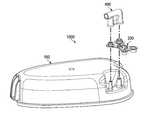
- FIG. 2depicts an exploded view of one embodiment of the present multi-conduit connector, canister lid, cap sleeve, and multi-conduit housing.
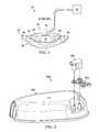
- FIG. 3depicts an assembly view of the multi-conduit connector, canister lid, cap sleeve, and multi-conduit housing.
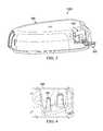
- FIG. 4depicts a perspective view of a portion of the canister lid of FIGS. 2 and 3 .
- FIG. 5depicts a side view of one embodiment of the present cap sleeve.
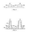
- FIG. 6depicts a side cross-sectional view of the cap sleeve of FIG. 5 coupled to the portion of the canister lid of FIG. 4 .
- FIG. 7depicts a cross-sectional view of one embodiment of the multi-conduit housing.
- FIG. 8depicts a cross-sectional assembly view of the canister lid of FIG. 3 , the cap sleeve of FIG. 4 and the multi-conduit housing of FIG. 6 .
- Coupledis defined as connected, although not necessarily directly, and not necessarily mechanically; two items that are “coupled” may be integral with each other.
- the terms “a” and “an”are defined as one or more unless this disclosure explicitly requires otherwise.
- the terms “substantially,” “approximately,” and “about”are defined as largely but not necessarily wholly what is specified, as understood by a person of ordinary skill in the art.
- a connector that “comprises,” “has,” “includes” or “contains” one or more elementspossesses those one or more elements, but is not limited to possessing only those elements.
- the connectorin a connector that comprises a nipple and a port, the connector includes the specified elements but is not limited to having only those elements.
- such a connectorcould also include an annular sleeve.
- a device or structure that is configured in a certain wayis configured in at least that way, but it can also be configured in other ways than those specifically described.
- Embodiments of the multi-conduit connector apparatus depictedmay be used in a variety of applications.
- a non-limiting example of a use for a multi-conduit connector apparatusis in the field of negative pressure wound therapy (NPWT).
- NGWTnegative pressure wound therapy
- the connector apparatuscan link more than one conduit to a wound dressing and a wound treatment apparatus.
- FIG. 1shows an embodiment of a wound treatment system 10 .
- apparatus 10comprises a wound-treatment apparatus 14 , and a wound dressing 18 coupled to apparatus 14 by a conduit 22 .
- conduit 22further comprises a conduit 450 and a conduit 460 .
- dressing 18is configured to be coupled to (and is shown coupled to) a wound 26 of a patient 30 . More particularly, in the embodiment shown, dressing 18 comprises a wound insert 34 and a drape 38 .
- wound insert 34is configured to be positioned (and is shown positioned) on wound 26 (e.g., on or adjacent to wound surface 42 ), and/or drape 38 is configured to be coupled to (and is shown coupled to) skin 46 of the patient adjacent to wound 26 such that drape 38 covers wound insert 34 and wound 26 , and forms a space 50 between drape 38 and wound 26 (e.g., wound surface 42 ).
- Apparatus 14can comprise, for example, a vacuum source configured to be actuatable (and/or actuated) to apply negative pressure (e.g., via conduit 22 ) to wound dressing 18 , a fluid source configured to be actuatable (and/or actuated) to deliver (e.g., via conduit 22 ) a fluid (for example, an instillation fluid such as a medicinal fluid, antibacterial fluid, or an irrigation fluid) to wound dressing 18 .
- Wound treatment apparatus 14may further comprise multi-conduit connector apparatus 1000 depicted in FIG. 2 and FIG. 3 .
- System 10can be implemented and/or actuated and/or coupled to patient 30 in any of various configurations and/or methods similar to those described in the prior art.
- various wound therapy systems and componentsare commercially available through and/or from KCI USA, Inc. of San Antonio, Tex., U.S.A., and/or its subsidiary and related companies (collectively, “KCI”).
- Conduits 22 , 450 , 460can comprise a single lumen conduit (e.g., switched between a vacuum source and/or a fluid source and apparatus 14 ), or can comprise multiple single-lumen conduits or a multi-lumen conduit such that, for example, fluid can be delivered and/or negative pressure can be applied to wound dressing 18 individually and/or simultaneously.
- a single lumen conduite.g., switched between a vacuum source and/or a fluid source and apparatus 14
- multiple single-lumen conduits or a multi-lumen conduitsuch that, for example, fluid can be delivered and/or negative pressure can be applied to wound dressing 18 individually and/or simultaneously.
- conduits 22 , 450 , 460can comprise, for example, multiple lumens (e.g., as in a single conduit with a central limit for application of negative pressure and/or fluid delivery and one or more peripheral lumens disposed adjacent or around the central lumen such that the peripheral lumens can be coupled to a pressure sensor to sense and/or detect a pressure or negative pressure between drape 38 and surface 42 (e.g. in space 50 ), as described in the Hunt and Boynton patents incorporated above.
- system 10further comprises a wound dressing connection pad 54 configured to be coupled (and shown coupled) to conduit 22 .
- a suitable connection pad 54is the “V.A.C. T.R.A.C.® Pad,” commercially available from KCI.
- a suitable drape 38includes the “V.A.C.® Drape” commercially available from KCI.
- FIG. 2 and FIG. 3one example of a multi-conduit connector apparatus 1000 is shown that comprises embodiments of a canister lid 100 , a cap sleeve 200 , and a multi-conduit housing 400 is shown.
- FIG. 2shows an exploded view
- FIG. 3shows an assembly view in which canister lid 100 , cap sleeve 200 , and multi-conduit housing 400 are coupled together.
- cap sleeve 200is placed over nipples 110 , 120 on canister lid 100 .
- Multi conduit housing 400is placed over canister lid 100 and cap sleeve 200 .
- canister lid 100 , cap sleeve 200 , and/or multi-conduit housing 400may be comprised of rubber or plastic. In some embodiments, canister lid 100 , cap sleeve 200 , and multi-conduit housing 400 may be designed for a single use.
- Canister lid 100comprises first nipple 110 and second nipple 120 .
- First nipple 110may be configured to be coupled to a first outlet 451 shown in FIG. 7 .
- Second nipple 120may be configured to be coupled to an second outlet 461 shown in FIG. 7 .
- first nipple 110is configured to be coupled to a vacuum pump, a pressure sensor, or both.
- second nipple 120is configured to be coupled to an exudate receptacle. In other embodiments second nipple 120 is configured to be coupled to a source of medicaments.
- Cap sleeve 200comprises a first annular sleeve 210 and a second annular sleeve 220 .
- First annular sleeve 210 and second annular sleeve 220comprises a first clearance shoulder 230 a on the outer surface of the sleeve.
- Second annular sleeve 220comprises a second clearance shoulder 230 b on the outer surface of the sleeve.
- Some embodiments of cap sleeve 200may comprise a hinge and a lid (not shown) for each annular sleeve 210 , 220 coupled to the hinge. Other embodiments may have a separate lid piece (not shown) for the annular sleeves 210 , 220 .
- Cap sleeve 200is coupled to canister lid 100 .
- cap sleeve 200may be removably coupled to canister lid 100 .
- cap sleeve 200may be permanently affixed to canister lid 100 .
- First annular sleeve 210engages first nipple 110 .
- Second annular sleeve 220engages second nipple 120 .
- Annular sleeves 210 , 220may be substantially in the shape of a circular ring in some embodiments. In other embodiments, annular sleeves 210 , 220 may be substantially in the shape of a triangular ring, a square ring, or any other ring shape.
- Multi-conduit housing 400comprises a first port 410 and a second port 420 .
- First port 410is configured to engage first nipple 110 .
- Second port 420is configured to engage second nipple 120 .
- First port 410comprises engagement tab 430 and a plurality of sealing ridges 440 .
- Second port 420comprises engagement tab 430 and a plurality of sealing ridges 440 .
- Engagement tabs 430are configured to engage clearance shoulders 230 a , 230 b .
- Sealing ridges 440are configured to engage first nipple 110 and second nipple 120 .
- engagement tab 430 and sealing ridges 440are made of a deformable material, including but not limited to rubber or plastic.
- Ports 410 , 420are structural elements of multi-conduit housing 400 that are configured to be coupled to nipples 110 , 120 .
- Ports 410 , 420are substantially the inverse shape of the corresponding nipples 110 , 120 .
- nipples 110 , 120are substantially in the shape of a frustum.
- corresponding ports 410 , 420are also in the shape of a frustum.
- Nipples 110 , 120 and ports 410 , 420may also be in the shape of cylinders, cones, prisms, or any other shape about which a seal can be created.
- Multi-conduit housing 400further comprises a first conduit 450 and a second conduit 460 .
- First conduit 450is configured to be coupled to a wound site.
- Multi-conduit housing 400further comprises a first outlet 451 .
- first outlet 451is configured to be coupled to first nipple 110 .
- First conduit 450is in fluid communication with first outlet 451 .
- Second conduit 460is configured to be coupled to a wound site and further comprises a second outlet 461 .
- second outlet 461is configured to be coupled to second nipple 120 .
- First conduit 450 and second conduit 460may be coaxial or parallel.
- Second conduit 460is in fluid communication with second outlet 461 .
- Cap sleeve 200is coupled to canister lid 100 .
- cap sleeve 200may be removably coupled to canister lid 100 .
- cap sleeve 200may be permanently affixed to canister lid 100 .
- First annular sleeve 210engages first nipple 110 .
- Second annular sleeve 220engages second nipple 120 .
- Multi-conduit housing 400engages both cap sleeve 200 and canister lid 100 .
- First port 410engages first nipple 110 .
- First outlet 451is in fluid communication with first nipple 110 .
- Second port 420engages second nipple 120 .
- Second outlet 461is in fluid communication with second nipple 120 .
- Engagement tab 430engages clearance shoulders 230 a , 230 b , creating a seal between first port 410 and first annular sleeve 210 , and also creating a seal between second port 420 and second annular sleeve 220 .
- Sealing ridges 440engage first nipple 110 , creating a seal between first port 410 and first nipple 110 .
- Sealing ridges 440also engage second nipple 120 , creating a seal between second port 420 and second nipple 120 .
- First nipple 110further comprises first clearance shoulder 230 a .
- Second nipple 120also further comprises second clearance shoulder 230 b.
- cap sleeve 200is coupled to canister lid 100 during the manufacturing process.
- cap sleeve 200is installed by a user.
- a usermay engage multi-conduit housing 400 with first nipple 110 and second nipple 120 .
- the usermay apply a downward force to multi-conduit housing 400 until engagement tabs 430 passes clearance shoulders 230 a , 230 b and can move no further.
- an audible soundmay be heard once multi-conduit housing 400 is fully engaged.
Landscapes
- Health & Medical Sciences (AREA)
- Heart & Thoracic Surgery (AREA)
- Engineering & Computer Science (AREA)
- Veterinary Medicine (AREA)
- General Health & Medical Sciences (AREA)
- Anesthesiology (AREA)
- Biomedical Technology (AREA)
- Hematology (AREA)
- Life Sciences & Earth Sciences (AREA)
- Animal Behavior & Ethology (AREA)
- Public Health (AREA)
- Vascular Medicine (AREA)
- Pulmonology (AREA)
- Mechanical Engineering (AREA)
- Surgery (AREA)
- Media Introduction/Drainage Providing Device (AREA)
- External Artificial Organs (AREA)
Abstract
Description
Claims (17)
Priority Applications (3)
| Application Number | Priority Date | Filing Date | Title |
|---|---|---|---|
| US13/017,857US8454567B2 (en) | 2010-02-01 | 2011-01-31 | Multi-conduit connectors and methods for negative pressure wound therapy |
| US13/874,974US9205246B2 (en) | 2010-02-01 | 2013-05-01 | Multi-conduit connectors and methods for negative pressure wound therapy |
| US14/930,479US9956328B2 (en) | 2010-02-01 | 2015-11-02 | Multi-conduit connectors and methods for negative pressure wound therapy |
Applications Claiming Priority (2)
| Application Number | Priority Date | Filing Date | Title |
|---|---|---|---|
| US30036210P | 2010-02-01 | 2010-02-01 | |
| US13/017,857US8454567B2 (en) | 2010-02-01 | 2011-01-31 | Multi-conduit connectors and methods for negative pressure wound therapy |
Related Child Applications (1)
| Application Number | Title | Priority Date | Filing Date |
|---|---|---|---|
| US13/874,974ContinuationUS9205246B2 (en) | 2010-02-01 | 2013-05-01 | Multi-conduit connectors and methods for negative pressure wound therapy |
Publications (2)
| Publication Number | Publication Date |
|---|---|
| US20110190717A1 US20110190717A1 (en) | 2011-08-04 |
| US8454567B2true US8454567B2 (en) | 2013-06-04 |
Family
ID=44342263
Family Applications (3)
| Application Number | Title | Priority Date | Filing Date |
|---|---|---|---|
| US13/017,857Active2031-04-10US8454567B2 (en) | 2010-02-01 | 2011-01-31 | Multi-conduit connectors and methods for negative pressure wound therapy |
| US13/874,974Active2031-10-24US9205246B2 (en) | 2010-02-01 | 2013-05-01 | Multi-conduit connectors and methods for negative pressure wound therapy |
| US14/930,479Active2032-02-29US9956328B2 (en) | 2010-02-01 | 2015-11-02 | Multi-conduit connectors and methods for negative pressure wound therapy |
Family Applications After (2)
| Application Number | Title | Priority Date | Filing Date |
|---|---|---|---|
| US13/874,974Active2031-10-24US9205246B2 (en) | 2010-02-01 | 2013-05-01 | Multi-conduit connectors and methods for negative pressure wound therapy |
| US14/930,479Active2032-02-29US9956328B2 (en) | 2010-02-01 | 2015-11-02 | Multi-conduit connectors and methods for negative pressure wound therapy |
Country Status (1)
| Country | Link |
|---|---|
| US (3) | US8454567B2 (en) |
Cited By (1)
| Publication number | Priority date | Publication date | Assignee | Title |
|---|---|---|---|---|
| US11189813B2 (en) | 2014-09-16 | 2021-11-30 | Arnold Leiboff | Wound management method and apparatus |
Families Citing this family (5)
| Publication number | Priority date | Publication date | Assignee | Title |
|---|---|---|---|---|
| DK3481349T3 (en)* | 2016-07-08 | 2021-07-12 | Convatec Technologies Inc | Flexible vacuum system |
| EP3852695A4 (en)* | 2018-09-19 | 2022-07-13 | DeRoyal Industries, Inc. | TUBE CONNECTION SYSTEM FOR VACUUM WOUND THERAPY |
| USD935033S1 (en) | 2020-03-05 | 2021-11-02 | Deroyal Industries, Inc. | Negative pressure wound therapy canister |
| USD935034S1 (en) | 2020-03-05 | 2021-11-02 | Deroyal Industries, Inc. | Negative pressure wound therapy canister |
| USD935035S1 (en) | 2020-03-05 | 2021-11-02 | Deroyal Industries, Inc. | Negative pressure wound therapy canister |
Citations (6)
| Publication number | Priority date | Publication date | Assignee | Title |
|---|---|---|---|---|
| US4804366A (en) | 1987-10-29 | 1989-02-14 | Baxter International Inc. | Cartridge and adapter for introducing a beneficial agent into an intravenous delivery system |
| US4850978A (en) | 1987-10-29 | 1989-07-25 | Baxter International Inc. | Drug delivery cartridge with protective cover |
| US5685842A (en) | 1996-04-22 | 1997-11-11 | Abbott Laboratories | Drug delivery system and method |
| US6957779B2 (en) | 2001-11-20 | 2005-10-25 | Microlin, L.C. | Foldable, refillable, sustained-release fluid delivery system |
| US7153294B1 (en)* | 2004-06-16 | 2006-12-26 | H2Or, Inc. | Surgical vacuum canister |
| US20100106116A1 (en)* | 2008-10-29 | 2010-04-29 | Tyler Simmons | Medical canister connectors |
Family Cites Families (124)
| Publication number | Priority date | Publication date | Assignee | Title |
|---|---|---|---|---|
| US1355846A (en) | 1920-02-06 | 1920-10-19 | David A Rannells | Medical appliance |
| US2547758A (en) | 1949-01-05 | 1951-04-03 | Wilmer B Keeling | Instrument for treating the male urethra |
| US2632443A (en) | 1949-04-18 | 1953-03-24 | Eleanor P Lesher | Surgical dressing |
| GB692578A (en) | 1949-09-13 | 1953-06-10 | Minnesota Mining & Mfg | Improvements in or relating to drape sheets for surgical use |
| US2682873A (en) | 1952-07-30 | 1954-07-06 | Johnson & Johnson | General purpose protective dressing |
| NL189176B (en) | 1956-07-13 | 1900-01-01 | Hisamitsu Pharmaceutical Co | PLASTER BASED ON A SYNTHETIC RUBBER. |
| US2969057A (en) | 1957-11-04 | 1961-01-24 | Brady Co W H | Nematodic swab |
| US3066672A (en) | 1960-09-27 | 1962-12-04 | Jr William H Crosby | Method and apparatus for serial sampling of intestinal juice |
| US3367332A (en) | 1965-08-27 | 1968-02-06 | Gen Electric | Product and process for establishing a sterile area of skin |
| US3520300A (en) | 1967-03-15 | 1970-07-14 | Amp Inc | Surgical sponge and suction device |
| US3568675A (en) | 1968-08-30 | 1971-03-09 | Clyde B Harvey | Fistula and penetrating wound dressing |
| US3682180A (en) | 1970-06-08 | 1972-08-08 | Coilform Co Inc | Drain clip for surgical drain |
| BE789293Q (en) | 1970-12-07 | 1973-01-15 | Parke Davis & Co | MEDICO-SURGICAL DRESSING FOR BURNS AND SIMILAR LESIONS |
| US3826254A (en) | 1973-02-26 | 1974-07-30 | Verco Ind | Needle or catheter retaining appliance |
| DE2527706A1 (en) | 1975-06-21 | 1976-12-30 | Hanfried Dr Med Weigand | DEVICE FOR THE INTRODUCTION OF CONTRAST AGENTS INTO AN ARTIFICIAL INTESTINAL OUTLET |
| DE2640413C3 (en) | 1976-09-08 | 1980-03-27 | Richard Wolf Gmbh, 7134 Knittlingen | Catheter monitor |
| NL7710909A (en) | 1976-10-08 | 1978-04-11 | Smith & Nephew | COMPOSITE STRAPS. |
| GB1562244A (en) | 1976-11-11 | 1980-03-05 | Lock P M | Wound dressing materials |
| US4080970A (en) | 1976-11-17 | 1978-03-28 | Miller Thomas J | Post-operative combination dressing and internal drain tube with external shield and tube connector |
| US4139004A (en) | 1977-02-17 | 1979-02-13 | Gonzalez Jr Harry | Bandage apparatus for treating burns |
| US4184510A (en) | 1977-03-15 | 1980-01-22 | Fibra-Sonics, Inc. | Valued device for controlling vacuum in surgery |
| US4165748A (en) | 1977-11-07 | 1979-08-28 | Johnson Melissa C | Catheter tube holder |
| US4245637A (en) | 1978-07-10 | 1981-01-20 | Nichols Robert L | Shutoff valve sleeve |
| SE414994B (en) | 1978-11-28 | 1980-09-01 | Landstingens Inkopscentral | VENKATETERFORBAND |
| GB2047543B (en) | 1978-12-06 | 1983-04-20 | Svedman Paul | Device for treating tissues for example skin |
| US4266545A (en) | 1979-04-06 | 1981-05-12 | Moss James P | Portable suction device for collecting fluids from a closed wound |
| US4284079A (en) | 1979-06-28 | 1981-08-18 | Adair Edwin Lloyd | Method for applying a male incontinence device |
| US4261363A (en) | 1979-11-09 | 1981-04-14 | C. R. Bard, Inc. | Retention clips for body fluid drains |
| US4569348A (en) | 1980-02-22 | 1986-02-11 | Velcro Usa Inc. | Catheter tube holder strap |
| WO1981002516A1 (en) | 1980-03-11 | 1981-09-17 | E Schmid | Cushion for holding an element of grafted skin |
| US4297995A (en) | 1980-06-03 | 1981-11-03 | Key Pharmaceuticals, Inc. | Bandage containing attachment post |
| US4333468A (en) | 1980-08-18 | 1982-06-08 | Geist Robert W | Mesentery tube holder apparatus |
| US4465485A (en) | 1981-03-06 | 1984-08-14 | Becton, Dickinson And Company | Suction canister with unitary shut-off valve and filter features |
| US4392853A (en) | 1981-03-16 | 1983-07-12 | Rudolph Muto | Sterile assembly for protecting and fastening an indwelling device |
| US4373519A (en) | 1981-06-26 | 1983-02-15 | Minnesota Mining And Manufacturing Company | Composite wound dressing |
| US4392858A (en) | 1981-07-16 | 1983-07-12 | Sherwood Medical Company | Wound drainage device |
| US4419097A (en) | 1981-07-31 | 1983-12-06 | Rexar Industries, Inc. | Attachment for catheter tube |
| AU550575B2 (en) | 1981-08-07 | 1986-03-27 | Richard Christian Wright | Wound drainage device |
| SE429197B (en) | 1981-10-14 | 1983-08-22 | Frese Nielsen | SAR TREATMENT DEVICE |
| DE3146266A1 (en) | 1981-11-21 | 1983-06-01 | B. Braun Melsungen Ag, 3508 Melsungen | COMBINED DEVICE FOR A MEDICAL SUCTION DRAINAGE |
| US4551139A (en) | 1982-02-08 | 1985-11-05 | Marion Laboratories, Inc. | Method and apparatus for burn wound treatment |
| US4475909A (en) | 1982-05-06 | 1984-10-09 | Eisenberg Melvin I | Male urinary device and method for applying the device |
| EP0100148B1 (en) | 1982-07-06 | 1986-01-08 | Dow Corning Limited | Medical-surgical dressing and a process for the production thereof |
| NZ206837A (en) | 1983-01-27 | 1986-08-08 | Johnson & Johnson Prod Inc | Thin film adhesive dressing:backing material in three sections |
| US4548202A (en) | 1983-06-20 | 1985-10-22 | Ethicon, Inc. | Mesh tissue fasteners |
| US4540412A (en) | 1983-07-14 | 1985-09-10 | The Kendall Company | Device for moist heat therapy |
| US4543100A (en) | 1983-11-01 | 1985-09-24 | Brodsky Stuart A | Catheter and drain tube retainer |
| US4525374A (en) | 1984-02-27 | 1985-06-25 | Manresa, Inc. | Treating hydrophobic filters to render them hydrophilic |
| CA1286177C (en) | 1984-05-03 | 1991-07-16 | Smith And Nephew Associated Companies Plc | Adhesive wound dressing |
| US4897081A (en) | 1984-05-25 | 1990-01-30 | Thermedics Inc. | Percutaneous access device |
| US5215522A (en) | 1984-07-23 | 1993-06-01 | Ballard Medical Products | Single use medical aspirating device and method |
| GB8419745D0 (en) | 1984-08-02 | 1984-09-05 | Smith & Nephew Ass | Wound dressing |
| US4872450A (en) | 1984-08-17 | 1989-10-10 | Austad Eric D | Wound dressing and method of forming same |
| US4826494A (en) | 1984-11-09 | 1989-05-02 | Stryker Corporation | Vacuum wound drainage system |
| US4655754A (en) | 1984-11-09 | 1987-04-07 | Stryker Corporation | Vacuum wound drainage system and lipids baffle therefor |
| US4605399A (en) | 1984-12-04 | 1986-08-12 | Complex, Inc. | Transdermal infusion device |
| US5037397A (en) | 1985-05-03 | 1991-08-06 | Medical Distributors, Inc. | Universal clamp |
| US4640688A (en) | 1985-08-23 | 1987-02-03 | Mentor Corporation | Urine collection catheter |
| US4710165A (en) | 1985-09-16 | 1987-12-01 | Mcneil Charles B | Wearable, variable rate suction/collection device |
| US4758220A (en) | 1985-09-26 | 1988-07-19 | Alcon Laboratories, Inc. | Surgical cassette proximity sensing and latching apparatus |
| US5045077A (en)* | 1985-11-25 | 1991-09-03 | Blake Joseph W Iii | Body cavity drainage implement |
| US4733659A (en) | 1986-01-17 | 1988-03-29 | Seton Company | Foam bandage |
| EP0256060A1 (en) | 1986-01-31 | 1988-02-24 | OSMOND, Roger L. W. | Suction system for wound and gastro-intestinal drainage |
| US4838883A (en) | 1986-03-07 | 1989-06-13 | Nissho Corporation | Urine-collecting device |
| JPS62281965A (en) | 1986-05-29 | 1987-12-07 | テルモ株式会社 | Catheter and catheter fixing member |
| GB8621884D0 (en) | 1986-09-11 | 1986-10-15 | Bard Ltd | Catheter applicator |
| GB2195255B (en) | 1986-09-30 | 1991-05-01 | Vacutec Uk Limited | Apparatus for vacuum treatment of an epidermal surface |
| US4743232A (en) | 1986-10-06 | 1988-05-10 | The Clinipad Corporation | Package assembly for plastic film bandage |
| DE3634569A1 (en) | 1986-10-10 | 1988-04-21 | Sachse Hans E | CONDOM CATHETER, A URINE TUBE CATHETER FOR PREVENTING RISING INFECTIONS |
| JPS63135179A (en) | 1986-11-26 | 1988-06-07 | 立花 俊郎 | Subcataneous drug administration set |
| GB8628564D0 (en) | 1986-11-28 | 1987-01-07 | Smiths Industries Plc | Anti-foaming agent suction apparatus |
| GB8706116D0 (en) | 1987-03-14 | 1987-04-15 | Smith & Nephew Ass | Adhesive dressings |
| US4787888A (en) | 1987-06-01 | 1988-11-29 | University Of Connecticut | Disposable piezoelectric polymer bandage for percutaneous delivery of drugs and method for such percutaneous delivery (a) |
| US4863449A (en) | 1987-07-06 | 1989-09-05 | Hollister Incorporated | Adhesive-lined elastic condom cathether |
| US5176663A (en) | 1987-12-02 | 1993-01-05 | Pal Svedman | Dressing having pad with compressibility limiting elements |
| US4906240A (en) | 1988-02-01 | 1990-03-06 | Matrix Medica, Inc. | Adhesive-faced porous absorbent sheet and method of making same |
| US4985019A (en) | 1988-03-11 | 1991-01-15 | Michelson Gary K | X-ray marker |
| GB8812803D0 (en) | 1988-05-28 | 1988-06-29 | Smiths Industries Plc | Medico-surgical containers |
| US4919654A (en) | 1988-08-03 | 1990-04-24 | Kalt Medical Corporation | IV clamp with membrane |
| US5000741A (en) | 1988-08-22 | 1991-03-19 | Kalt Medical Corporation | Transparent tracheostomy tube dressing |
| US5059596A (en) | 1989-01-16 | 1991-10-22 | Roussel Uclaf | Azabicyclo compounds |
| GB8906100D0 (en) | 1989-03-16 | 1989-04-26 | Smith & Nephew | Laminates |
| US4969880A (en) | 1989-04-03 | 1990-11-13 | Zamierowski David S | Wound dressing and treatment method |
| US5527293A (en) | 1989-04-03 | 1996-06-18 | Kinetic Concepts, Inc. | Fastening system and method |
| US5100396A (en) | 1989-04-03 | 1992-03-31 | Zamierowski David S | Fluidic connection system and method |
| US5261893A (en) | 1989-04-03 | 1993-11-16 | Zamierowski David S | Fastening system and method |
| JP2719671B2 (en) | 1989-07-11 | 1998-02-25 | 日本ゼオン株式会社 | Wound dressing |
| US5358494A (en) | 1989-07-11 | 1994-10-25 | Svedman Paul | Irrigation dressing |
| US5232453A (en) | 1989-07-14 | 1993-08-03 | E. R. Squibb & Sons, Inc. | Catheter holder |
| GB2235877A (en) | 1989-09-18 | 1991-03-20 | Antonio Talluri | Closed wound suction apparatus |
| US5134994A (en) | 1990-02-12 | 1992-08-04 | Say Sam L | Field aspirator in a soft pack with externally mounted container |
| US5092858A (en) | 1990-03-20 | 1992-03-03 | Becton, Dickinson And Company | Liquid gelling agent distributor device |
| US5149331A (en) | 1991-05-03 | 1992-09-22 | Ariel Ferdman | Method and device for wound closure |
| US5278100A (en) | 1991-11-08 | 1994-01-11 | Micron Technology, Inc. | Chemical vapor deposition technique for depositing titanium silicide on semiconductor wafers |
| US5645081A (en) | 1991-11-14 | 1997-07-08 | Wake Forest University | Method of treating tissue damage and apparatus for same |
| US5636643A (en) | 1991-11-14 | 1997-06-10 | Wake Forest University | Wound treatment employing reduced pressure |
| US5279550A (en) | 1991-12-19 | 1994-01-18 | Gish Biomedical, Inc. | Orthopedic autotransfusion system |
| US5167613A (en) | 1992-03-23 | 1992-12-01 | The Kendall Company | Composite vented wound dressing |
| FR2690617B1 (en) | 1992-04-29 | 1994-06-24 | Cbh Textile | TRANSPARENT ADHESIVE DRESSING. |
| DE4306478A1 (en) | 1993-03-02 | 1994-09-08 | Wolfgang Dr Wagner | Drainage device, in particular pleural drainage device, and drainage method |
| US5342376A (en) | 1993-05-03 | 1994-08-30 | Dermagraphics, Inc. | Inserting device for a barbed tissue connector |
| US6241747B1 (en) | 1993-05-03 | 2001-06-05 | Quill Medical, Inc. | Barbed Bodily tissue connector |
| US5344415A (en) | 1993-06-15 | 1994-09-06 | Deroyal Industries, Inc. | Sterile system for dressing vascular access site |
| US5437651A (en) | 1993-09-01 | 1995-08-01 | Research Medical, Inc. | Medical suction apparatus |
| US5549584A (en) | 1994-02-14 | 1996-08-27 | The Kendall Company | Apparatus for removing fluid from a wound |
| US5556375A (en) | 1994-06-16 | 1996-09-17 | Hercules Incorporated | Wound dressing having a fenestrated base layer |
| US5607388A (en) | 1994-06-16 | 1997-03-04 | Hercules Incorporated | Multi-purpose wound dressing |
| US5664270A (en) | 1994-07-19 | 1997-09-09 | Kinetic Concepts, Inc. | Patient interface system |
| DE69505545T2 (en) | 1994-08-22 | 1999-03-11 | Kinetic Concepts Inc | WOUND DRAINAGE DEVICE |
| DE29504378U1 (en) | 1995-03-15 | 1995-09-14 | MTG Medizinisch, technische Gerätebau GmbH, 66299 Friedrichsthal | Electronically controlled low-vacuum pump for chest and wound drainage |
| GB9523253D0 (en) | 1995-11-14 | 1996-01-17 | Mediscus Prod Ltd | Portable wound treatment apparatus |
| US6135116A (en) | 1997-07-28 | 2000-10-24 | Kci Licensing, Inc. | Therapeutic method for treating ulcers |
| AU755496B2 (en) | 1997-09-12 | 2002-12-12 | Kci Licensing, Inc. | Surgical drape and suction head for wound treatment |
| GB9719520D0 (en) | 1997-09-12 | 1997-11-19 | Kci Medical Ltd | Surgical drape and suction heads for wound treatment |
| US6071267A (en) | 1998-02-06 | 2000-06-06 | Kinetic Concepts, Inc. | Medical patient fluid management interface system and method |
| US6488643B1 (en) | 1998-10-08 | 2002-12-03 | Kci Licensing, Inc. | Wound healing foot wrap |
| US6287316B1 (en) | 1999-03-26 | 2001-09-11 | Ethicon, Inc. | Knitted surgical mesh |
| US7799004B2 (en) | 2001-03-05 | 2010-09-21 | Kci Licensing, Inc. | Negative pressure wound treatment apparatus and infection identification system and method |
| US6856821B2 (en) | 2000-05-26 | 2005-02-15 | Kci Licensing, Inc. | System for combined transcutaneous blood gas monitoring and vacuum assisted wound closure |
| US6991643B2 (en) | 2000-12-20 | 2006-01-31 | Usgi Medical Inc. | Multi-barbed device for retaining tissue in apposition and methods of use |
| ES2220734T3 (en) | 2000-02-24 | 2004-12-16 | Venetec International, Inc. | UNIVERSAL FIXING SYSTEM FOR CATETER. |
| US6540705B2 (en) | 2001-02-22 | 2003-04-01 | Core Products International, Inc. | Ankle brace providing upper and lower ankle adjustment |
| US20090306631A1 (en)* | 2006-03-14 | 2009-12-10 | Carl Joseph Santora | Manifold for administering reduced pressure to a subcutaneous tissue site |
| GB0811572D0 (en)* | 2008-06-24 | 2008-07-30 | Smith & Nephew | Negitive pressure wound theraphy device |
- 2011
- 2011-01-31USUS13/017,857patent/US8454567B2/enactiveActive
- 2013
- 2013-05-01USUS13/874,974patent/US9205246B2/enactiveActive
- 2015
- 2015-11-02USUS14/930,479patent/US9956328B2/enactiveActive
Patent Citations (6)
| Publication number | Priority date | Publication date | Assignee | Title |
|---|---|---|---|---|
| US4804366A (en) | 1987-10-29 | 1989-02-14 | Baxter International Inc. | Cartridge and adapter for introducing a beneficial agent into an intravenous delivery system |
| US4850978A (en) | 1987-10-29 | 1989-07-25 | Baxter International Inc. | Drug delivery cartridge with protective cover |
| US5685842A (en) | 1996-04-22 | 1997-11-11 | Abbott Laboratories | Drug delivery system and method |
| US6957779B2 (en) | 2001-11-20 | 2005-10-25 | Microlin, L.C. | Foldable, refillable, sustained-release fluid delivery system |
| US7153294B1 (en)* | 2004-06-16 | 2006-12-26 | H2Or, Inc. | Surgical vacuum canister |
| US20100106116A1 (en)* | 2008-10-29 | 2010-04-29 | Tyler Simmons | Medical canister connectors |
Non-Patent Citations (1)
| Title |
|---|
| International Search Report and Written Opinion, issued in International Patent Application No. PCT/US2011/022571, mailed on Oct. 20, 2011. |
Cited By (1)
| Publication number | Priority date | Publication date | Assignee | Title |
|---|---|---|---|---|
| US11189813B2 (en) | 2014-09-16 | 2021-11-30 | Arnold Leiboff | Wound management method and apparatus |
Also Published As
| Publication number | Publication date |
|---|---|
| US9956328B2 (en) | 2018-05-01 |
| US20130237936A1 (en) | 2013-09-12 |
| US20110190717A1 (en) | 2011-08-04 |
| US20160114089A1 (en) | 2016-04-28 |
| US9205246B2 (en) | 2015-12-08 |
Similar Documents
| Publication | Publication Date | Title |
|---|---|---|
| US9956328B2 (en) | Multi-conduit connectors and methods for negative pressure wound therapy | |
| AU2018253553B2 (en) | Leak-resistant bandage systems and methods with hydrophilic foam wound insert for fluid-instillation and/or negative-pressure wound therapies | |
| US20200289739A1 (en) | Combination fluid instillation and negative pressure dressing | |
| US20190365968A1 (en) | System and method for interfacing with a reduced pressure dressing | |
| US8377017B2 (en) | Low-profile reduced pressure treatment system |
Legal Events
| Date | Code | Title | Description |
|---|---|---|---|
| FEPP | Fee payment procedure | Free format text:PAYOR NUMBER ASSIGNED (ORIGINAL EVENT CODE: ASPN); ENTITY STATUS OF PATENT OWNER: LARGE ENTITY | |
| STCF | Information on status: patent grant | Free format text:PATENTED CASE | |
| FEPP | Fee payment procedure | Free format text:PAYER NUMBER DE-ASSIGNED (ORIGINAL EVENT CODE: RMPN); ENTITY STATUS OF PATENT OWNER: LARGE ENTITY Free format text:PAYOR NUMBER ASSIGNED (ORIGINAL EVENT CODE: ASPN); ENTITY STATUS OF PATENT OWNER: LARGE ENTITY | |
| AS | Assignment | Owner name:KCI LICENSING, INC., TEXAS Free format text:ASSIGNMENT OF ASSIGNORS INTEREST;ASSIGNORS:LONG, JUSTIN ALEXANDER;TOUT, AIDAN MARCUS;RANDOLPH, LARRY TAB;AND OTHERS;SIGNING DATES FROM 20100401 TO 20100513;REEL/FRAME:032576/0507 | |
| AS | Assignment | Owner name:WILMINGTON TRUST, NATIONAL ASSOCIATION, AS COLLATERAL AGENT, MINNESOTA Free format text:SECOND LIEN SECURITY AGREEMENT;ASSIGNORS:KCI USA, INC.;LIFECELL CORPORATION;KCI LICENSING, INC.;REEL/FRAME:040098/0268 Effective date:20160920 Owner name:WILMINGTON TRUST, NATIONAL ASSOCIATION, AS COLLATE Free format text:SECOND LIEN SECURITY AGREEMENT;ASSIGNORS:KCI USA, INC.;LIFECELL CORPORATION;KCI LICENSING, INC.;REEL/FRAME:040098/0268 Effective date:20160920 | |
| AS | Assignment | Owner name:WILMINGTON TRUST, NATIONAL ASSOCIATION, AS COLLATERAL AGENT, MINNESOTA Free format text:LIMITED THIRD LIEN INTELLECTUAL PROPERTY SECURITY AGREEMENT;ASSIGNORS:KCI USA, INC.;LIFECELL CORPORATION;KCI LICENSING, INC.;REEL/FRAME:040291/0237 Effective date:20161006 Owner name:WILMINGTON TRUST, NATIONAL ASSOCIATION, AS COLLATE Free format text:LIMITED THIRD LIEN INTELLECTUAL PROPERTY SECURITY AGREEMENT;ASSIGNORS:KCI USA, INC.;LIFECELL CORPORATION;KCI LICENSING, INC.;REEL/FRAME:040291/0237 Effective date:20161006 | |
| FPAY | Fee payment | Year of fee payment:4 | |
| AS | Assignment | Owner name:KCI USA, INC., TEXAS Free format text:RELEASE OF SECURITY INTEREST REEL/FRAME 040098/0268;ASSIGNOR:WILMINGTON TRUST;REEL/FRAME:041666/0320 Effective date:20170203 | |
| AS | Assignment | Owner name:KCI USA, INC., TEXAS Free format text:RELEASE OF SECURITY INTEREST IN PATENTS;ASSIGNOR:WILMINGTON TRUST, NATIONAL ASSOCIATION;REEL/FRAME:050966/0547 Effective date:20191011 Owner name:KCI LICENSING, INC., TEXAS Free format text:RELEASE OF SECURITY INTEREST IN PATENTS;ASSIGNOR:WILMINGTON TRUST, NATIONAL ASSOCIATION;REEL/FRAME:050966/0547 Effective date:20191011 | |
| MAFP | Maintenance fee payment | Free format text:PAYMENT OF MAINTENANCE FEE, 8TH YEAR, LARGE ENTITY (ORIGINAL EVENT CODE: M1552); ENTITY STATUS OF PATENT OWNER: LARGE ENTITY Year of fee payment:8 | |
| AS | Assignment | Owner name:3M INNOVATIVE PROPERTIES COMPANY, MINNESOTA Free format text:ASSIGNMENT OF ASSIGNORS INTEREST;ASSIGNOR:KCI LICENSING, INC.;REEL/FRAME:064718/0544 Effective date:20230824 | |
| AS | Assignment | Owner name:SOLVENTUM INTELLECTUAL PROPERTIES COMPANY, MINNESOTA Free format text:ASSIGNMENT OF ASSIGNORS INTEREST;ASSIGNOR:3M INNOVATIVE PROPERTIES COMPANY;REEL/FRAME:066432/0376 Effective date:20240201 | |
| MAFP | Maintenance fee payment | Free format text:PAYMENT OF MAINTENANCE FEE, 12TH YEAR, LARGE ENTITY (ORIGINAL EVENT CODE: M1553); ENTITY STATUS OF PATENT OWNER: LARGE ENTITY Year of fee payment:12 |