US8454563B2 - Trocar and cannula assembly having improved conical valve, and methods related thereto - Google Patents
Trocar and cannula assembly having improved conical valve, and methods related theretoDownload PDFInfo
- Publication number
- US8454563B2 US8454563B2US12/901,393US90139310AUS8454563B2US 8454563 B2US8454563 B2US 8454563B2US 90139310 AUS90139310 AUS 90139310AUS 8454563 B2US8454563 B2US 8454563B2
- Authority
- US
- United States
- Prior art keywords
- valve
- friction
- periphery
- valve body
- reduction features
- Prior art date
- Legal status (The legal status is an assumption and is not a legal conclusion. Google has not performed a legal analysis and makes no representation as to the accuracy of the status listed.)
- Active, expires
Links
Images


Classifications
- A—HUMAN NECESSITIES
- A61—MEDICAL OR VETERINARY SCIENCE; HYGIENE
- A61B—DIAGNOSIS; SURGERY; IDENTIFICATION
- A61B17/00—Surgical instruments, devices or methods
- A61B17/34—Trocars; Puncturing needles
- A61B17/3498—Valves therefor, e.g. flapper valves, slide valves
- A—HUMAN NECESSITIES
- A61—MEDICAL OR VETERINARY SCIENCE; HYGIENE
- A61B—DIAGNOSIS; SURGERY; IDENTIFICATION
- A61B17/00—Surgical instruments, devices or methods
- A61B17/34—Trocars; Puncturing needles
- A61B17/3462—Trocars; Puncturing needles with means for changing the diameter or the orientation of the entrance port of the cannula, e.g. for use with different-sized instruments, reduction ports, adapter seals
- A—HUMAN NECESSITIES
- A61—MEDICAL OR VETERINARY SCIENCE; HYGIENE
- A61B—DIAGNOSIS; SURGERY; IDENTIFICATION
- A61B17/00—Surgical instruments, devices or methods
- A61B2017/00831—Material properties
- A61B2017/0084—Material properties low friction
- A61B2017/00845—Material properties low friction of moving parts with respect to each other
- A—HUMAN NECESSITIES
- A61—MEDICAL OR VETERINARY SCIENCE; HYGIENE
- A61B—DIAGNOSIS; SURGERY; IDENTIFICATION
- A61B17/00—Surgical instruments, devices or methods
- A61B17/34—Trocars; Puncturing needles
- A61B17/3462—Trocars; Puncturing needles with means for changing the diameter or the orientation of the entrance port of the cannula, e.g. for use with different-sized instruments, reduction ports, adapter seals
- A61B2017/3464—Trocars; Puncturing needles with means for changing the diameter or the orientation of the entrance port of the cannula, e.g. for use with different-sized instruments, reduction ports, adapter seals with means acting on inner surface of valve or seal for expanding or protecting, e.g. inner pivoting fingers
Definitions
- the present disclosurerelates generally to medical devices, and more particularly to trocar systems, cannulas, valves, and methods related thereto.
- trocar systemshave been developed for various endoscopic applications in the field of medicine. These trocar systems conventionally include a cannula, through which a trocar or obturator or other endoscopic-related tool extends.
- one or more valvesis necessarily positioned within or connected to the proximal end of the cannula.
- Many such valvesare disadvantageously bulky and awkward to use, and complex, multi-component mechanical valves can be difficult and costly to manufacture, and can have increased risk of failure relative to non-mechanical counterparts.
- mechanical valvestypically have little or no flexibility.
- Valve improvementscan serve to enhance handling of trocar systems by medical professionals, facilitating better performance and improving patient surgical experience. Therefore, it is readily apparent that there is a need for an improved conical valve and related trocar and cannula assembly, and methods related thereto, where performance is enhanced, risk of failure is mitigated, and cost-effective production and manufacture is available.
- the present assemblyovercomes the above-mentioned disadvantages and meets the recognized need for such a device by providing a trocar and cannula assembly with improved conical valve, and methods related thereto, wherein an improved single-piece valve design allows for easier stretch of the body of the valve, reduces friction, and promotes retention of original shape of the distal center hole, thereby providing improvement, at least in the ability to seal during aggressive manipulation of instruments through the port.
- the present systemis a trocar and cannula assembly with improved conical valve that incorporates a plurality of ribs to restrict and/or otherwise influence valve movement, and a plurality of improved convolutes and bumps to enhance performance characteristics.
- Embodiments of the present inventionadvantageously provide a valve having a design to provide a secured seal around a plurality of tools that individually and separately extend through the valve, providing for ease of insertion and retraction of various laparoscopic surgical instruments, as well as other surgically-related items with varying diameters, wherein the present system is configured to advantageously accept a broad range thereof. Further, problematical instruments do not get obstructed or caught, such as may occur in some disadvantageous multi-component valve assemblies. Embodiments of the present disclosure also advantageously provide a trocar system having relatively low costs associated with the manufacturing of components of the system, e.g., valves, and thereby reduce the costs associated with the trocar system.
- Embodiments of the present disclosureadditionally advantageously provide a more flexible trocar system which is effective during various endoscopic surgical procedures.
- Embodiments of the present inventionfurther advantageously provide enhanced methods of forming a seal around tools and of using a trocar system during surgical procedures.
- Embodiments of the presentfurther advantageously provide a valve having peripheries fixedly connected to a valve housing, such that the valve may operate like a membrane, and embodiments of the valve advantageously allow one type of valve, cannula, or trocar system to be readily used for various types and diameters of tools used by medical personnel.
- embodiments of the present disclosurefurther provide a valve having advantageously improved anti-friction features that facilitate insertion and removal of instruments therethrough.
- Still further embodiments of the present disclosuremay provide for the formation of these anti-friction features according to a new multi-shot liquid silicone rubber process, wherein liquid silicone rubber and traditional thermoplastic elements may be combined in a single molded part.
- plurality of bump featuresmay be molded as a thermoplastic material, with a very low coefficient of friction.
- the system of the present disclosurein its preferred form is a trocar system comprising a cannula having an elongate cannula body, with medial and distal portions having a first diameter.
- the cannula bodyhas a proximal portion, connected to the medial portion and opposingly positioned relative to the distal portion, wherein the proximal portion has a second diameter, wherein the second diameter is greater than the first diameter.
- a valve housingis detachably connected to the proximal portion of the cannula body, with an axis and first opening at a proximal end of the valve housing, a second opening at a distal end of the valve housing, and an axially downward facing shoulder.
- the first opening of the valve housingis preferably defined by a plurality of sidewalls extending in a substantially axial direction, and has a first opening diameter.
- the trocar systemalso includes a cap assembly which includes at least one valve positioned within the valve housing.
- the at least one valvecan include a valve body having an annular-shaped valve opening adapted to individually and separately receive a plurality of different elongate tools. Each of the tools have a different diameter therethrough so that when any one of the plurality of elongate tools is positioned through the valve opening, a septum seal is maintained between peripheries of the valve body surrounding the valve opening and abuttingly contacting outer peripheries of the any one of the plurality of elongate tools extending therethrough.
- the valve bodypreferably has a periphery valve section connected to and extending radially outwardly from peripheries of the valve body.
- the periphery valve sectionincludes an outer ring with an outer perimeter thereof defining an outer perimeter of the septum valve, the outer ring engaging the axially downward facing shoulder of the valve housing, and convolutes defined between the outer ring and the valve body.
- the periphery valve sectionalso has a plurality of rib members, each radially extending at least a portion of the distance between an outer perimeter of the valve body and the outer perimeter of the periphery valve section, and symmetrically positioned spaced-apart from each other.
- the periphery valve sectionmay have a greater flexibility than the valve body.
- the trocar systemalso preferably includes a compression ring positioned in the valve housing adjacent the septum valve.
- the compression ringcompresses the outer ring of the septum valve against the axially downward facing shoulder of the valve housing in order to fixedly position the septum valve within the valve housing.
- the compression ringhas a compression ring opening substantially aligned with the first opening of the valve housing.
- the trocar systemfurther comprises a plurality of tools that each have an elongate body for extending through the valve housing, the valve opening, and the cannula.
- the cap assembly of the trocar systemmay include, but is not limited to, a valve housing having at least one opening formed in line with an axis of the valve housing, with the at least one opening being defined by a plurality of sidewalls extending in a substantially axial direction.
- the cap assemblyalso may include at least one valve positioned adjacent to the at least one opening of the valve housing.
- the at least one valveincludes a valve body having an annular-shaped valve opening adapted to individually and separately receive a plurality of different elongate tools.
- Each of the elongate toolscan have a different diameter so that when any one of the plurality of elongate tools is positioned through the valve opening, and when the valve is abuttingly contacting outer peripheries of any one of the plurality of diameter elongate tools extending therethrough, a septum seal is maintained between peripheries of the valve body surrounding the valve opening.
- the valve bodyalso has a periphery valve section connected to and extending radially outwardly from peripheries of the valve body. The periphery valve section has one or more convolutes within the periphery valve section.
- the periphery valve sectionalso has a plurality of rib members radially extending at least a portion of the distance between an outer perimeter of the valve body and an outer perimeter of the periphery valve section, and may have a circumferential baffle defined between the plurality of convolutes and the inner perimeter of the outer ring.
- the systemmay include a valve housing adapted to detachably connect to a cannula and characterized by having a proximal end housing portion, a distal end housing portion, and a medial housing portion connected therebetween having a proximal valve housing inner perimeter surface and a distal valve housing inner perimeter surface which can be of the same or different diameters.
- the proximal end housing portioncan include a first opening having a first opening diameter defined by portions of an inner valve housing sidewall extending distally in a substantially axial direction.
- the proximal end housing portioncan also include an annular valve ring recess adapted to receive an annular valve ring which surrounds the first opening.
- the distal end housing portioncan include a second opening diameter defined by a distal valve housing sidewall extending in a substantially axial direction.
- the at least one valve positioned within a valve housingmay include a first valve having a valve body which includes a proximal valve section fixedly positioned within the valve housing and a distal valve section extending axially from the proximal valve section and into the proximal portion of the cannula.
- the proximal valve sectioncan include a valve ring positioned in the valve ring recess of the valve housing.
- the valve ringhas a proximal surface, a distal surface, an inner perimeter surface, and an outer perimeter surface defining an outer perimeter of the valve body.
- the proximal surface and the distal surface of the periphery valve sectionare each preferably further defined by two sub-element surfaces, wherein the first sub-element surface of the proximal surface is defined in a first plane and proximate the inner perimeter of the periphery valve section, and the second sub-element surface of the proximal surface is defined in a second plane and proximate the outer perimeter of the periphery valve section.
- the periphery valve sectionmay include a circumferential baffle element related to the proximal valve section of the valve body, wherein the circumferential baffle element may preferably be defined in the second plane proximate the outer perimeter of the periphery valve section.
- the proximal valve section of the valve bodycan also include a plurality of convolutes, each preferably having a first sidewall extending radially inwardly from a portion of the circumferential baffle and a second sidewall extending axially from the first sidewall substantially parallel to the inner perimeter surface of the valve ring and forming an inner radial periphery of the proximal valve section.
- the inner perimeter surface of the periphery valve section, the first sidewall, and the second sidewall of each of the plurality of convolutespreferably form a respective convolute recess for each of the plurality of convolutes.
- the proximal valve section of the valve bodycan also include a plurality of rib members, each radially extending at least a portion of the distance between the inner radial periphery of the proximal valve section and inner perimeter surface of the valve ring and can be symmetrically positioned spaced-apart from each other.
- each of the plurality of rib membersextends radially from the inner radial periphery of the proximal valve section to the circumferential baffle element, wherein the circumferential baffle element extends radially from the plurality of convolutes to the inner perimeter surface of the valve ring.
- the distal valve section of the valve bodycan include a valve extension extending axially from the plurality of convolutes.
- the valve extensioncan include a proximal end portion substantially connected to a distal portion of each of the plurality of convolutes, a distal end portion, and a substantially conically shaped medial portion connected to and extending therebetween.
- An annular-shaped valve openingis positioned in the distal end portion of the valve extension and is adapted to individually and separately receive therethrough any one of a plurality of different elongate tools, each having a different diameter so that when any one of the plurality of elongate tools is positioned through the valve opening, a seal, e.g., septum seal, is maintained between peripheries of the valve extension surrounding the valve opening and outer peripheries of any one of the plurality of elongate tools extending therethrough.
- a seale.g., septum seal
- the first valvemay also include a compression ring positioned in the valve housing abuttingly contacting an axially facing distal surface of the valve ring to hold the valve ring in the valve ring recess and to compress the valve ring against an axially facing inner surface of the proximal end housing portion of the valve housing adjacent the valve ring recess in order to fixedly position the valve within the valve housing.
- the compression ringmay include a compression ring opening substantially aligned axially with the first opening of the valve housing to allow extension of the plurality of elongate tools therethrough, an outer perimeter surface having a radial diameter sized so that the compression ring substantially abuttingly contacts the distal valve housing inner perimeter surface when positioned within the valve housing, and an annular flange extending into each one of the plurality of convolute recesses to individually and separately engage a corresponding one of the plurality of convolutes to further enhance positioning and securing of the first valve within the valve housing.
- the cap assemblycan also include a second valve to advantageously help ensure inter-cavity sealing.
- the second valvecan include an annular flange portion spaced axially from the valve ring of the first valve and having a radial diameter sized so that the annular flange portion substantially abuttingly contacts both the distal valve inner housing perimeter surface and an axially facing distal surface of the compression ring adjacent the compression ring opening to enhance positioning of the second valve at least partially within the valve housing.
- the second valvecan also have a second valve opening positioned within the annular flange portion and substantially aligned axially with the first opening of the valve housing to allow extension of the plurality of elongate tools therethrough, an annular-shaped sidewall connected to the annular flange and extending distally in a substantially axial direction when positioned in the valve housing, and a pair of valve flaps connected to and extending inwardly from the annular-shaped sidewall and having at least one slit along common peripheral edges thereof through which the plurality of tools extend individually and separately.
- the second valvecan be held in place through use of a cap seal ring positioned at least partially within the valve housing and positioned to abuttingly contact a distal surface of the annular flange portion of the second valve when the second valve is positioned in the valve housing.
- the cap seal ringcan have an axially extending annular-shaped flange axially spaced apart from the compression ring to provide a slot or recess to releasably receive the annular flange portion of the second valve.
- the cap seal ringcan also include a plurality of radially extending flanges each adapted to engage other peripheries of a separate one of the plurality of radially extending flanges of the cannula to slidably detachably connect the valve housing to the cannula.
- Embodiments of the present disclosurealso preferably include methods of using a trocar system.
- one method embodimentmay include the step of providing a cap assembly in a trocar system.
- the cap assemblyhas a septum valve including a valve body having an annular-shaped valve opening positioned in a medial portion of the valve body adapted to receive individually and separate a plurality of tools therethrough so that when any one of the plurality of tools is positioned through the valve opening abuttingly contacting outer peripheries of the any one of the plurality of tools extending therethrough, a septum seal is maintained between peripheries of the valve body surrounding the valve opening.
- the valve bodycan include a periphery valve section connected to and extending radially outwardly from peripheries of the valve body and having an outer perimeter thereof adapted to be fixedly connected to the valve housing.
- the periphery valve sectioncan also have a plurality of rib members each radially extending at least a portion of the distance between an outer perimeter of the valve body and the outer perimeter of the periphery valve section and symmetrically positioned spaced-apart from each other.
- the periphery valve sectioncan also have a circumferential baffle member defined proximate the outer perimeter of the periphery valve section, wherein the plurality of rib members preferably extend between the outer perimeter of the valve body and the circumferential baffle member.
- the periphery valve sectioncan have a greater flexibility than the valve body.
- the method of using a trocar systemcan also include the step of inserting a tool through the septum valve and cap assembly comprising the septum valve thereof.
- the periphery valve sectionmay be deformed temporarily so that the valve body extends distally by contact pressure from the tool and so that a distal end of the tool is guided toward the valve opening and then the periphery valve section is refracted to its selected biased position upon the complete insertion of the tool.
- the method of using a trocar systemcan also include the step of guiding the tool to the septum valve with a substantially cylindrical-shaped cap assembly opening when the tool is being inserted through the cap assembly.
- the method of using a trocar systemcan further include the steps of extending the tool through a cannula body matingly connected to the cap assembly at a proximal portion thereof, detaching the cap assembly from the proximal portion of the cannula body, and removing tissue or other specimen from the cannula body.
- the methodcan include the step of providing a cap assembly in a trocar system including a valve positioned at least partially within a valve housing.
- the valvecan include a valve body having a proximal valve section positioned within the valve housing and a distal valve section extending axially from the proximal valve section and including a valve extension having a proximal end portion, a distal end portion, and a substantially conically shaped medial portion connect to and extending therebetween.
- a valve openingis positioned in the distal end portion of the valve extension and is adapted to individually and separately receive therethrough any one of a plurality of different elongate tools.
- the methodcan also include the step of inserting a tool through the cap assembly including the valve extension and a valve opening thereof, during which the valve extension guides the distal end of the tool to the valve opening and upon reaching the valve opening, the valve opening is deformed temporarily by contact pressure from the tool so that upon the complete insertion of the tool, a seal is formed around outer peripheries of the tool.
- the methodfurther includes the steps of guiding the tool to the valve extension with a substantially cylindrical-shaped cap assembly opening when the tool is being inserted through the cap assembly, extending the tool through a cannula body matingly connected to the cap assembly at a proximal portion thereof, detaching the cap assembly from the proximal portion of the cannula body, and removing tissue or other specimen from the cannula body.
- the valvealso preferably includes a plurality of closely and symmetrically spaced friction-reduction features to advantageously minimize electrostatic forces between instruments and the valve.
- a reduction in electrostatic adhesioncan be realized from the friction-reduction features, preferably protrusions formed on the inner and outer surfaces of the conically shaped medial portion, proximate the distal end and the valve opening.
- a first circumferential row of protrusionsis defined proximate the valve opening in a closely-spaced conformation, whereafter a second circumferential row of protrusions is defined in a position of greater distance relative to the valve opening, wherein the same total number of protrusions is preferably defined in the second row as the first row, but given the increased diameter of the conical valve at the location of the second row relative to that of the first row, the second row protrusions are less closely-spaced.
- further rowsare defined in similar fashion.
- the positioning of the protrusions of each adjacent circumferential rowmay also be juxtaposed, such that a radial twist pattern may be defined by the protrusions about the conical valve proximate the distal end and the valve opening.
- the friction-reduction featuresessentially serve to create a gap between an instrument surface and a flat area of the valve, beneficially decreasing the total area of contact in the trocar system otherwise potentially faced with a relatively large surface of contact area, high pressure contact, and high shear stress deformation.
- the protrusionsthus function to reduce undesirable pressure contact between the instrument and the valve.
- embodiments wherein the protrusionsmay be formed from a thermoplastic material with a low coefficient of friction may serve to limit frictional forces even further by effectively changing the coefficient of friction acting on the entire valve system.
- a further improvement proximate the distal end of the valverelates to the definition of the plurality of friction-reduction features definition on both a distal surface and a proximal surface of the distal end of the valve, wherein each protrusion preferably forms a cone, wherein the shape and placement of friction-reduction features enhances friction reduction. That is, kinetic friction between the valve and related instruments is advantageously minimized as the valve opening is deformed temporarily by contact pressure from the tool, wherein contact area between the valve and the instruments is reduced. Moreover, elongation or other reactive force redirection by the circumferential baffle element serves to minimize deformation of the valve opening as well.
- the friction-reduction featurescan reduce the resistive forces between the contact surfaces of an inserted instrument and the valve without compromise to the septum seal or to the inherent flexibility and adaptability of the valve of the present invention, wherein a broad endoscopic instrument diameter range, from about 5 mm to 15 mm diameter, can be successfully accepted.
- the friction-reduction features, both the plurality of protrusions, or conesare preferably defined proximate the apical end of the valve, in anticipation of contact with the plurality of elongate tools extended therethrough, and are further preferably defined on both opposing surfaces in order that advantageous minimization of electrostatic forces may be realized also during contact between the valve body and the second valve.
- these friction-reduction featuresmay be formed from material with a low coefficient of friction relative to the material of the valve body, such as a thermoplastic, wherein further friction-reduction benefits may be realized.
- Embodiments of the present inventionalso include methods of forming a valve for a trocar system.
- a method of forming a valve for a trocar systemcan include first inserting a valve having a valve body into the valve housing.
- a compression ringfor example, coated with an ultraviolet bonding agent, is then placed into the valve housing adjacent and abuttingly contacting the valve in a “stacked” fashion.
- the second valveis inserted into the valve housing adjacent and abuttingly contacting the compression ring, and a cap seal ring coated with an ultraviolet bonding agent is placed into the valve housing abuttingly contacting outer peripheries of the second valve.
- Both the compression ring and cap seal ringcan be coated with an ultraviolet bonding agent, along with the outer peripheries thereof abuttingly contacting the inner peripheries of the valve housing.
- the cap assemblyWhen constructing a trocar system, the cap assembly is abuttingly and releasably connected to a cannula.
- the proximal end portion of the cannula bodyhas at least one valve housing mating portion associated therewith, and the cap seal ring positioned in the valve housing also has at least one cannula body mating portion or flange associated therewith so that the cap assembly matingly attaches to the cannula body in a secured position and whereby movement of the cap assembly, e.g., rotation, by a hand of a user, releases, e.g., unsecures or unlocks, the respective mating portions for ready removal of the cap assembly by the user with the valve and second valve and so that specimens, e.g., tissue, can be readily removed from the cannula body without damage by the first and second valve.
- the extraction of large tissue samples and/or gauze packscan be accomplished without removing the cannula from the area where various endoscopic procedures take place.
- FIG. 1is a perspective environmental view of a trocar system positioned within a layer of epidermis of a patient, according to a prior art embodiment
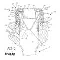
- FIG. 2is a fragmentary sectional view of a trocar system having first and second valves, according to a prior art embodiment
- FIG. 3is a side elevational view of a trocar system according to an embodiment of the present disclosure
- FIG. 4is a top plan view of a cap assembly of a trocar system according to an embodiment of the present disclosure
- FIG. 5is an exploded view of a cap assembly of a trocar system according to a prior art embodiment
- FIG. 6is an environmental perspective view of a valve, valve mold, and a slab illustrating the formation of a valve according to a prior art embodiment
- FIG. 7is a perspective view of a valve of a trocar system according to a prior art embodiment
- FIG. 8is a magnified, cut-away surface view of a valve of a trocar system according to a prior art embodiment
- FIG. 9is a cross-sectional, cut-away view, taken along line 26 - 26 of the valve of FIG. 7 , according to a prior art embodiment
- FIG. 10is a graphical representation of the parabolic relationship between frictional force and roughness
- FIG. 11is a perspective view of a valve according to an embodiment of the present disclosure.
- FIG. 12is a proximal view of the valve of FIG. 11 ;
- FIG. 13is a cross-sectional view, taken along line A-A of the valve of FIG. 11 , according to an embodiment of the present disclosure.
- FIG. 14is a magnified, cut-away surface view of the valve of FIG. 13 , according to an embodiment of the present disclosure.
- FIGS. 1-2 and 5 - 9it is instructive to reference prior art embodiments, as previously disclosed in commonly-owned U.S. patent application Ser. No. 11/503,314 and U.S. patent application Ser. No. 11/807,202, wherein the presently disclosed trocar and cannula assembly 400 having improved conical valve 450 may include one or more features in common therewith. That is, prior art nonplanar valves 150 and 150 ′ are first referenced and instructively described relative to use with cannula 40 and common features of cap assembly 130 shared with prior trocar system 120 and the presently disclosed trocar system 420 . Thereafter, embodiments of improved conical valve 450 are described, with preferred particularity.
- Cap assembly 130 of prior art trocar system 120preferably comprises valve housing 132 , wherein valve housing 132 may have, for example, a substantially annular shape, with proximal end housing portion 171 , distal end housing portion 173 , and medial housing portion 175 .
- Proximal end housing portion 171preferably includes first opening 131 having a first opening diameter defined by portions of inner valve housing sidewall 177 and extending distally in a substantially axial direction.
- Inner valve housing sidewall 177forming first opening 131 , extends substantially axially downward toward a valve opening, referenced prior art valve opening 151 , 151 ′ of prior art valve 150 , 150 ′, respectively, or valve opening 451 of improved conical valve 450 .
- the upper portion of the first opening 131can be rounded so as not to have any right angle edges at the first opening 131 , but with the resulting cross-section forming a substantially cylindrical first opening 131 extending along the same axis as that for the prior art valve opening 151 , 151 ′ or improved conical valve opening 451 .
- the proximal end housing portion 171can also include an annular valve ring recess 179 for retaining the prior art valve 150 , 150 ′ or improved conical valve 450 .
- the distal end housing portion 173can include a second opening 133 having a second opening diameter defined by a distal valve housing sidewall 181 extending in a substantially axial direction.
- the medial housing portion 175can includes a first proximal valve housing inner perimeter surface 183 and a second distal valve housing inner perimeter surface 185 which can have a perimeter size or circumference the same or slightly larger than that of the first proximal valve housing inner perimeter surface 183 .
- Cap assembly 130may also include compression ring 136 positioned in valve housing 132 at a medially axial position between first and second openings 131 , 133 of valve housing 132 , abuttingly contacting axially facing distal surface 199 of valve ring 195 .
- Compression ring 136includes compression ring opening 137 , substantially aligned axially with first opening 131 of valve housing 132 to allow extension of the plurality of elongate tools therethrough.
- Compression ring opening 137can also be sized to allow at least portions of inner valve housing sidewall 177 and valve 150 , 150 ′ or 450 to extend therethrough.
- Compression ring 136also includes outer perimeter surface 217 having a radial diameter sized so that compression ring 136 substantially abuttingly contacts proximal valve housing inner perimeter surface 183 when positioned within valve housing 132 and includes annular flange 219 extending preferably into each one of the plurality of convolute recesses 411 .
- Compression ring 136is positioned to compress valve ring 195 , 195 ′ or 495 against an axially facing inner surface and an axially facing shoulder of proximal end housing portion 171 of valve housing 132 which together, along with a portion of first proximal valve housing inner perimeter surface 183 of medial housing portion 175 , form valve ring recess 179 and/or compress the valve ring 195 against first proximal valve housing inner perimeter surface 183 of medial housing portion 175 , to hold valve ring 195 in valve ring recess 179 to fixedly position the valve 150 , 150 ′ or 450 within valve housing 132 .
- compression ring 136is positioned so that proximal valve housing inner perimeter surface 183 , surfaces forming valve ring recess 179 , and annular flange 219 of compression ring 136 rigidly hold valve ring 195 , 195 ′ or 495 within valve housing 132 .
- Annular flange 219 of compression ring 136can include a plurality of notches 221 symmetrically positioned spaced-apart from each other so that each of the notches 221 aligns with and receives a separate one of the plurality of rib members 459 to thereby rotationally align the compression ring 136 with the valve ring 495 when positioned in contact therewith.
- the annular flange 219can include a plurality of separate spaced apart flanges (not shown) having a gap between each pair of flanges defining the notch 221 and aligned with the plurality of rib members 459 to thereby enhance positioning of the valve ring 195 .
- the axially facing inner surface of the proximal end housing portion 171 of the valve housing 132can include one or more protuberances 205 extending at least partially along the length of the valve ring recess 179
- the proximal surface 197 of the valve ring 195can include one or more recesses 206 or can deform to form a recess 206 , as illustrated, to receive the one or more protuberances 205 to thereby enhance positioning of the valve ring 195 within the valve housing 132 .
- Cap assembly 130can also include second valve 160 .
- Second valve 160is advantageously positioned adjacent second opening 133 of valve housing 132 , abuttingly contacting compression ring 139 .
- Second valve 160advantageously has annular flange portion 162 spaced axially from the valve ring of the first valve 150 , 150 ′ or 450 .
- Annular flange portion 162can have a radial diameter sized so that annular flange portion 162 substantially abuttingly contacts the distal valve inner housing perimeter surface 185 and axially facing distal surface of compression ring 136 adjacent compression ring opening 137 to enhance the positioning of second valve 160 within valve housing 132 .
- Second valve 160includes second valve opening 223 positioned within annular flange portion 162 and, when positioned within valve housing 132 , is substantially aligned axially with first and second openings 131 , 133 , of valve housing 132 to allow extension of the plurality of elongate tools therethrough.
- Annular-shaped sidewalls 164are connected to annular flange portion 162 and extend distally in a substantially axial direction when positioned in valve housing 132 . At least one pair of valve flaps 166 is connected to and extends inwardly from sidewalls 164 and flange portion 162 . Sidewalls 164 , for example, can extend distally of the end of valve housing 132 so that flange portion 162 retains only portions of second valve 160 within valve housing 132 and yet slidably or in a spaced-apart relation have other portions which are positioned within proximal portion 48 of cannula body 42 .
- Second valve 160also advantageously can have ribs or rib members (not shown), e.g., formed integrally therewith as a single piece, and connected to sidewalls 164 to reduce drag as will be understood by those skilled in the art. Second valve 160 can also be advantageously impregnated with a lubricant such as an oil material to enhance performance thereof.
- valve opening 168can take other forms, such as an annular shaped opening or other known to those skilled in the art.
- Second valve 160in general, and the portion of sidewalls 164 surrounding opening 168 , in particular, can be formed of a flexible material similar to that used in forming the first valve 450 .
- the flexible materialadvantageously can include a silicon material coated in paralene to enhance the strength of valve 160 and to enhance sliding and/or sealing of the plurality of tools.
- a proximal surface of annular flange portion 162 of second valve 160can include an at least partially annular recess 227 or can deform to form recess 227 , as illustrated, to receive an at least partially annular protuberance 225 extending from a distal surface of compression ring 136 to thereby enhance positioning of second valve 160 at least partially within valve housing 132 .
- a distal surface of annular flange portion 162 of second valve 160can further include a second valve annular-shaped recess 229 adapted to receive an axially extending annular-shaped flange 272 of proximal portion 48 of cannula 40 to thereby enhance positioning of at least part of proximal portion 48 of cannula 40 within valve housing 132 .
- Cap assembly 130can also include cap seal ring 138 positioned at least partially within valve housing 132 and having an axially extending flange 274 positioned to abuttingly contact a distal surface of annular flange portion 162 of second valve 160 when positioned in valve housing 132 .
- Cap seal ring 138can include a plurality of radially extending flanges 135 , each adapted to engage outer peripheries of a separate one of the plurality of radially extending flanges 34 of cannula 40 to slidably detachably connect valve housing 132 to cannula 40 .
- Cannula 40can also include an annular shaped axially extending flange adapted to engage annular-shaped recess 229 of second valve 160 to thereby enhance positioning of cannula 40 securely against second valve 160 when positioned in engagement with radially extending flanges 135 of cap seal ring 138 .
- FIG. 6illustrates an exemplary construction process of a prior art cap assembly 130 , as instructive of the similar construction process of the presently disclosed cap assembly 430 .
- prior art valve 150(or similarly improved conical valve 450 , as may be so read throughout this and the immediately following exemplary cap assembly construction process paragraphs) is first inserted into valve housing 132 .
- compression ring 136for example, coated with an ultraviolet bonding agent, is placed into valve housing 132 adjacent and abuttingly contacting valve 150 in a “stacked” fashion.
- second valve 160is inserted into valve housing 132 adjacent and abuttingly contacting compression ring 136 , and cap seal ring 138 coated with an ultraviolet bonding agent is placed into valve housing 132 and abuttingly contacting outer peripheries of second valve 160 .
- Both compression ring 136 and cap seal ring 138can be coated with an ultraviolet bonding agent along the outer peripheries thereof abuttingly contacting the inner peripheries of valve housing 132 .
- cap assembly 130is formed as one unit.
- second valve 160can be readily removed and exchanged for a replacement.
- cap assembly 130When constructing a trocar system 120 , cap assembly 130 is then abuttingly connected to cannula 40 .
- Proximal end portion 48 of cannula body 42has at least one valve housing mating portion 34 associated therewith and cap seal ring 138 positioned in valve housing 132 also has at least one cannula body mating portion or flange 135 associated therewith so that cap assembly 130 matingly attaches to cannula body 42 in a secured position and whereby movement of cap assembly 130 , e.g., rotation, by a hand of a user releases, e.g., unsecures or unlocks, the respective mating portions 34 , 135 for ready removal of cap assembly 130 by the user with the first and second valves 450 , 160 , and so that specimens, e.g., tissue, can be readily removed from cannula body 42 without damage by the first and second valves 450 , 160 .
- the extraction of large tissue samples and/or gauze packscan be accomplished
- valve body 155 , 155 ′ or 455can include valve body 155 , 155 ′ or 455 , respectively, positioned at least partially within valve housing 132 , axially aligned with the first opening 131 of the valve housing 132 .
- Valve body 155 , 155 ′ or 455includes proximal valve section 191 , 191 ′ or 491 , respectively, fixedly positioned entirely within valve housing 132 , and distal valve section 193 , 193 ′ or 493 extending axially from proximal valve section 191 , 191 ′ or 491 .
- Valve 450has periphery valve section 456 connected to and extending radially outwardly from peripheries of the base of valve extension 452 .
- Periphery valve section 456includes valve ring 495 , defining an outer perimeter of valve 450 , and preferably has plurality of convolutes 458 , plurality of rib members 459 , and circumferential baffle 494 .
- Plurality of rib members 459each preferably extend radially at least a portion of the distance between peripheries of the base of valve extension 452 and valve ring 495 , preferably symmetrically positioned spaced-apart from each other.
- plurality of rib members 459preferably extend between the base of valve extension 452 and circumferential baffle 494 .
- valve ring 195 or 495has proximal surface 497 , distal surface 499 , inner perimeter surface 501 , and an outer perimeter surface 503 defining an outer perimeter of valve body 455 .
- Proximal valve section 491preferably has circumferential baffle 494 extending radially inwardly from inner perimeter surface 501 of valve ring 495 to outer sidewall 510 of plurality of convolutes 458 .
- Proximal valve section 491can include plurality of convolutes 458 , each having outer sidewall 510 extending from circumferential baffle 494 , first sidewall 507 extending axially and radially inwardly from outer sidewall 510 , and a second sidewall 509 extending axially from first sidewall 507 , substantially parallel to or slightly angled from inner perimeter surface 501 of valve ring 495 , and forming an inner radial periphery of proximal valve section 491 .
- Proximal surface 498 and distal surface 500 of periphery valve section 456are each further defined by two sub-elements surfaces, wherein first sub-element surface 502 of proximal surface 498 is defined in a first plane and proximate the inner perimeter of periphery valve section 456 , and second sub-element surface 504 of proximal surface 498 is defined in a second plane and proximate the outer perimeter of periphery valve section 456 .
- first sub-element surface 506 of distal surface 500is defined in a first plane and proximate the inner perimeter of periphery valve section 456
- second sub-element surface 508 of distal surface 500is defined in a second plane and proximate the outer perimeter of periphery valve section 456 . Accordingly, neither proximal surface 498 nor distal surface 500 of periphery valve section 456 is flat.
- Periphery valve section 456may include circumferential baffle element 494 , wherein second sub-element surface 504 of proximal surface 498 and second sub-element surface 508 of distal surface 500 are components thereof. That is, circumferential baffle element 494 is preferably related to proximal valve section 491 of valve 450 , wherein circumferential baffle element 494 is defined in the second plane proximate the outer perimeter of periphery valve section 456 .
- Proximal valve section 491 of valve 450can also include plurality of convolutes 458 , each having outer sidewall 510 extending axially from the second plane and circumferential baffle element 494 to the first plane and first sidewall 507 .
- the proximal valve section 491can also include a plurality of rib members 459 , each radially extending from circumferential baffle element 494 to inner perimeter surface 501 of the valve ring 495 and symmetrically positioned spaced-apart from each other.
- the distal valve section 493can extend axially from proximal valve section 491 and can include valve extension 452 extending axially from the plurality of convolutes 458 .
- the valve extension 452can have a proximal end portion 512 substantially connected to a distal portion of each of the plurality of convolutes 458 , a distal end portion 513 , and a medial portion 515 connected to and extending therebetween.
- medial portion 515can have a substantially frusto-conical or other similar conical-form shape, as illustrated.
- the distal valve section 493includes valve opening 451 positioned in distal end portion 513 of valve extension 452 , which can have, for example, an annular shape.
- the valve opening 451is adapted to individually and separately receive therethrough any one of the plurality of different elongate tools (not shown) each having a different diameter so that when any one of the plurality of elongate tools is positioned through valve opening 451 , a septum-type seal is maintained between peripheries of distal end portion 513 of valve extension 452 surrounding valve opening 451 and outer peripheries of any one of the plurality of elongate tools when extending therethrough.
- the plurality of toolseach have an elongate body for extending through valve housing 132 , valve opening 451 of valve 450 , and the cannula 40 .
- the plurality of convolutes 458are each positioned between and connected to any two adjacent rib members 459 . According to an embodiment of the convolutes 458 , each convolute 458 can be in a selected biased position before and after each of the plurality of different elongate tools, individually and separately, extends through the valve opening 451 . According to an embodiment of the present invention, the combination of the convolutes 458 , circumferential baffle 494 and valve extension 452 allow for axial movement of the tools without a corresponding movement within valve opening 451 with respect to outer peripheries of the tools.
- valve body 455in general, and the portion of valve extension 452 surrounding opening 451 , in particular, can be formed of a flexible material to provide the elastic range necessary to accommodate the plurality of elongate tools.
- the flexible materialadvantageously can include a silicon material coated with paralene, available through various manufacturers, including Dow Corning Corp., to enhance the strength of the valve 450 and to enhance sliding and sealing of the plurality of tools.
- a method of forming a trocar system 420as constructed, for example, the valve 450 advantageously has a stretching or elastic range to readily accommodate, e.g., auto-reduction, tools or other instruments having a diameter of about 5 millimeters to about 15 millimeters as understood by those skilled in the art while still maintaining pneumoperitoneum.
- the valve opening 451 of the valve body 455has a diameter less than the diameter of each of the tools that extend through valve 450 so that a secured seal is provided around outer peripheries of each of the tools.
- the second valve 160advantageously has this range as well, but individually can even have a greater range, e.g., 1 millimeter to 13 or 14 millimeters. Accordingly, with valve 450 and second valve 160 , in combination, the trocar system 420 advantageously can receive different diameter instruments without the necessity of switching cannulas or valve systems.
- Embodiments of the present inventionalso include a method of using a trocar system 420 , as with prior art trocar system 120 , including the steps of providing a cap assembly 130 , which includes valve 450 , or 150 , as described above, and inserting a tool through the valve 450 , or 150 , and cap assembly 130 .
- a cap assembly 130which includes valve 450 , or 150 , as described above, and inserting a tool through the valve 450 , or 150 , and cap assembly 130 .
- circumferential baffle 494convolutes 458 and valve extension 452 flex so that valve body 455 extends distally by contact pressure from the tool and so that a distal end of the tool is guided through valve opening 451 .
- valve 450is constructed in a thin and relatively conical shaped profile, valve 450 functions like a thin elastic membrane that flexes inwardly and outwardly along a fairly wide range of tool positions, without requiring valve opening 451 to “slide” along the outer peripheries of the respective tool once positioned through valve opening 451 , and does not float or rotate in the valve housing 132 .
- This methodalso includes extending the tool through a cannula body 42 matingly connected to the cap assembly 130 at a proximal portion 48 thereof.
- the methodfurther includes the steps of detaching the cap assembly 130 from the cannula body 42 and removing tissue or other specimen as understood by those skilled in the art from the cannula body 42 . Because various types and diameters of tools can be used by medical personnel, embodiments of a valve advantageously allow one type of valve, cannula, or trocar system to be readily used for all of these various sizes and types of tools.
- valve body 455in general, and the portion of valve extension 452 surrounding opening 451 , in particular, can be formed of a flexible material to provide the elastic range necessary to accommodate the plurality of elongate tools.
- the flexible materialadvantageously can include a silicon material coated with paralene, available through various manufacturers including Dow Corning Corp., to enhance the strength of valve 450 and to enhance sliding and sealing of the plurality of tools.
- valve extension 452The relationship between frictional force and roughness is parabolic, as depicted in FIG. 10 , wherein frictional forces are increased between both very smooth, as well as very rough surfaces, and wherein at the vertex of the parabola, a target roughness quality is represented that results in little or no frictional force.
- the smoothness of valve extension 452therefore, can be specifically adjusted relative to previously described valve extension 152 ′, such as seen in FIGS. 7-9 , wherein plurality of friction-reduction features 300 were defined, but, as will be further discussed, are presently improved.
- prior valve body 155 ′in general, and the portion of the valve extension 152 ′ proximate opening 151 ′ included plurality of friction-reduction features 300 to advantageously minimize electrostatic forces between instruments and the valve 150 ′.
- the plurality of friction-reduction features 300was configured to increase roughness of valve extension 152 ′ in such a manner that movement toward the vertex along the demonstrated parabolic curve relating frictional force and roughness can be realized, wherein plurality of friction-reduction features 300 was comprised of plurality of protrusions 302 , defined on outer surface 304 and inner surface 306 of valve extension 152 ′, generally over an area defined proximate and between medial portion 215 ′ and distal end portion 213 ′ of valve 150 ′.
- the friction-reduction features 300were defined proximate the apical end of the valve 150 ′ in anticipation of contact with the plurality of elongate tools extended therethrough, and were further defined on both opposing surfaces 304 - 306 in order that advantageous minimization of electrostatic forces may be realized also during contact between the valve body 155 ′ and the second valve 160 .
- the plurality of protrusions 302were tear-drop shaped, to functionally improve the prior manufacturing process, as well as serving to reduce the resistive forces between the contact surfaces of an inserted instrument and the valve 150 ′ without compromise to the septum seal or to the inherent flexibility and adaptability of the valve 150 ′.
- improved conical valve 450preferably has plurality of closely and symmetrically spaced friction-reduction features 600 , wherein increased concentration and relative proximity of friction-reduction features 600 was empirically determined to enhance minimization of electrostatic forces between instruments and valve 450 .
- Friction-reduction features 600are preferably protrusions formed on inner and outer surfaces, 504 and 506 , respectively, of conical valve 450 , proximate distal end 413 and valve opening 451 .
- first circumferential row 602 of protrusions 604is defined proximate valve opening 451 in a closely-spaced, essentially abutting conformation, whereafter second circumferential row 606 of protrusions 604 is defined in a position of greater distance from valve opening 451 relative to first circumferential row 602 , wherein the same total number of protrusions 604 is preferably defined in second row 606 as first row 602 , but given the increased diameter of conical valve 450 at the location of second row 606 relative to that of first row 602 , protrusions 604 of second circumferential row 606 are less closely-spaced than those of first circumferential row 602 . Thereafter, further plurality of rows 608 are defined in similar fashion.
- each adjacent circumferential row 608may also be juxtaposed, such that a radial twist pattern may be defined by the protrusions 604 about conical valve 450 proximate distal end 413 and valve opening 451 .
- Protrusions 604may be formed in essentially any shape capable of maintaining the preferred functionality of creating additional space between valve 450 and an instrument inserted therein, and thereby reducing surface area for frictional contact therebetween. Moreover, protrusions 604 may be formed according to a multi-shot liquid silicone rubber process, wherein liquid silicone rubber may be utilized for formation of valve body 455 and traditional thermoplastic elements may be utilized for formation of protrusions 604 , thus combining materials of differing coefficients of friction in a single molded part. In such manner, protrusions 604 may perform with action similar to that of ball bearing elements.
- a further improvement proximate distal end 413 of valve 450relates to the definition of the plurality of friction-reduction features 600 definition on both inner surface 504 and outer surface 506 of the distal end 413 of valve 450 , wherein each of the plurality of protrusions 604 is preferably shaped as a round-tipped cone 610 , wherein the position and shape of friction-reduction features effectively and measurably enhances friction reduction. That is, kinetic friction between valve 450 and related instruments is advantageously minimized as valve opening 451 is deformed temporarily by contact pressure from the tool, wherein contact area between valve 450 and the instruments is reduced.
- circumferential baffle 494serves to minimize deformation of the valve opening as well.
- the friction-reduction features 600can reduce the resistive forces between the contact surfaces of an inserted instrument and valve 450 without compromise to the septum seal or to the inherent flexibility and adaptability of valve 450 of the present invention, wherein a broad endoscopic instrument diameter range, from about 5 mm to 15 mm diameter, can be successfully accepted.
- the friction-reduction features 600are preferably defined proximate the apical end of valve 450 , in anticipation of contact with the plurality of elongate tools extended therethrough, and are further preferably defined on both opposing surfaces 504 and 506 in order that advantageous minimization of electrostatic forces may be realized also during contact between valve 450 and second valve 160 .
- Each protrusion 604is thus preferably shaped with a generally circular base and extending outward from inner and outer surfaces 504 and 506 , respectively, of valve 450 , to form cone 610 , preferably with a rounded tip 612 .
- This preferred shapealso serves to facilitate the manufacturing process, wherein successful formation and ejection of valve 450 from a mold is achieved more readily.
- the preferred round-tipped cone shapeis preferred.
- plurality of protrusions 604is depicted and described according to the preferred configuration, wherein a particular enhanced roughness quality is achieved, with measurable improvements over previous configurations, relative to frictional force, other arrangements could be utilized, including more rows, aligned rows, non-rows and/or an arrangement of protrusions with even closer relative proximity, even approaching or achieving an essentially solid configuration, such as an annular rib; however, resulting modification to the roughness and/or related electrostatic nature of the surface could influence the achieved performance enhancement relative to the preferred configuration.
Landscapes
- Health & Medical Sciences (AREA)
- Surgery (AREA)
- Life Sciences & Earth Sciences (AREA)
- Biomedical Technology (AREA)
- Nuclear Medicine, Radiotherapy & Molecular Imaging (AREA)
- Engineering & Computer Science (AREA)
- Pathology (AREA)
- Heart & Thoracic Surgery (AREA)
- Medical Informatics (AREA)
- Molecular Biology (AREA)
- Animal Behavior & Ethology (AREA)
- General Health & Medical Sciences (AREA)
- Public Health (AREA)
- Veterinary Medicine (AREA)
- Surgical Instruments (AREA)
Abstract
Description
Claims (19)
Priority Applications (2)
| Application Number | Priority Date | Filing Date | Title |
|---|---|---|---|
| US12/901,393US8454563B2 (en) | 2009-10-09 | 2010-10-08 | Trocar and cannula assembly having improved conical valve, and methods related thereto |
| US13/887,404US9066754B2 (en) | 2009-10-09 | 2013-05-06 | Trocar and cannula assembly having improved conical valve, and methods related thereto |
Applications Claiming Priority (2)
| Application Number | Priority Date | Filing Date | Title |
|---|---|---|---|
| US25019409P | 2009-10-09 | 2009-10-09 | |
| US12/901,393US8454563B2 (en) | 2009-10-09 | 2010-10-08 | Trocar and cannula assembly having improved conical valve, and methods related thereto |
Related Child Applications (1)
| Application Number | Title | Priority Date | Filing Date |
|---|---|---|---|
| US13/887,404ContinuationUS9066754B2 (en) | 2009-10-09 | 2013-05-06 | Trocar and cannula assembly having improved conical valve, and methods related thereto |
Publications (2)
| Publication Number | Publication Date |
|---|---|
| US20110087170A1 US20110087170A1 (en) | 2011-04-14 |
| US8454563B2true US8454563B2 (en) | 2013-06-04 |
Family
ID=43855401
Family Applications (2)
| Application Number | Title | Priority Date | Filing Date |
|---|---|---|---|
| US12/901,393Active2031-05-22US8454563B2 (en) | 2009-10-09 | 2010-10-08 | Trocar and cannula assembly having improved conical valve, and methods related thereto |
| US13/887,404Expired - Fee RelatedUS9066754B2 (en) | 2009-10-09 | 2013-05-06 | Trocar and cannula assembly having improved conical valve, and methods related thereto |
Family Applications After (1)
| Application Number | Title | Priority Date | Filing Date |
|---|---|---|---|
| US13/887,404Expired - Fee RelatedUS9066754B2 (en) | 2009-10-09 | 2013-05-06 | Trocar and cannula assembly having improved conical valve, and methods related thereto |
Country Status (1)
| Country | Link |
|---|---|
| US (2) | US8454563B2 (en) |
Cited By (4)
| Publication number | Priority date | Publication date | Assignee | Title |
|---|---|---|---|---|
| US20120071713A1 (en)* | 2010-09-17 | 2012-03-22 | Us Endoscopy | Biopsy inlet valve improvements |
| US20160022962A1 (en)* | 2011-12-09 | 2016-01-28 | Teleflex Medical Incorporated | Introducer assembly |
| USD956219S1 (en) | 2020-07-10 | 2022-06-28 | Covidien Lp | Port apparatus |
| USD963851S1 (en) | 2020-07-10 | 2022-09-13 | Covidien Lp | Port apparatus |
Families Citing this family (9)
| Publication number | Priority date | Publication date | Assignee | Title |
|---|---|---|---|---|
| US8257315B2 (en) | 2006-10-11 | 2012-09-04 | Ethicon Endo-Surgery, Inc. | Trocar seal with retraction induced hinge |
| WO2013123455A1 (en) | 2012-02-15 | 2013-08-22 | Intuitive Surgical Operations, Inc. | Low friction cannula seals for minimally invasive robotic surgery |
| ITBA20120020U1 (en)* | 2012-04-11 | 2013-10-12 | Vincenzo Nuzziello | "DOUBLE CHANNEL SURGICAL DEVICE FOR ABDOMINAL ACCESS" |
| EP2846713A1 (en) | 2012-05-09 | 2015-03-18 | EON Surgical Ltd. | Laparoscopic port |
| US9572626B2 (en) | 2013-02-15 | 2017-02-21 | Intuitive Surgical Operations, Inc. | Actuated cannula seal |
| CN104095672B (en)* | 2013-04-15 | 2019-04-30 | 广州迪克医疗器械有限公司 | A kind of universal sealing ring and puncture device |
| CN105615954B (en)* | 2014-11-08 | 2018-10-12 | 广州迪克医疗器械有限公司 | Puncture outfit containing silencing means |
| JP6560632B2 (en)* | 2016-02-22 | 2019-08-14 | 西島メディカル株式会社 | Trial rod |
| CA3218241A1 (en)* | 2021-07-20 | 2023-01-26 | James Y. Chon | Valved cannula assembly |
Citations (114)
| Publication number | Priority date | Publication date | Assignee | Title |
|---|---|---|---|---|
| US3939835A (en) | 1972-06-02 | 1976-02-24 | Henry Bridgman | Medical aspiration system vacuum level indicator |
| US4056116A (en) | 1976-09-08 | 1977-11-01 | Baxter Travenol Laboratories, Inc. | Valve for interconnecting sterile containers and the like |
| US4486024A (en) | 1983-05-17 | 1984-12-04 | Westinghouse Electric Corp. | Dual-ring gland seal for dynamoelectric machine rotor |
| US4493319A (en) | 1981-06-29 | 1985-01-15 | Cabot Medical Corporation | Ring applicator having floating inner tube |
| EP0131349A1 (en) | 1983-06-13 | 1985-01-16 | Hewlett-Packard Company | Circuit testing utilizing data compression and derivative mode vectors |
| US4723550A (en) | 1986-11-10 | 1988-02-09 | Cordis Corporation | Leakproof hemostasis valve with single valve member |
| US4842591A (en) | 1988-01-21 | 1989-06-27 | Luther Ronald B | Connector with one-way septum valve, and assembly |
| US4943280A (en) | 1987-12-31 | 1990-07-24 | United States Surgical Corporaiton | Self-seating flapper valve for an insufflation cannula assembly |
| US4960412A (en) | 1988-04-15 | 1990-10-02 | Universal Medical Instrument Corp. | Catheter introducing system |
| US5104383A (en) | 1989-10-17 | 1992-04-14 | United States Surgical Corporation | Trocar adapter seal and method of use |
| US5125553A (en) | 1987-03-02 | 1992-06-30 | Stryker Sales Corporation | Surgical suturing instrument and method |
| US5127909A (en) | 1990-04-05 | 1992-07-07 | United States Surgical Corporation | Flapper valve for an insufflation cannula assembly |
| US5141498A (en) | 1991-09-10 | 1992-08-25 | Unisurge, Incorporated | Flexible valve and device incorporating the same |
| US5150702A (en) | 1990-06-18 | 1992-09-29 | Olympus Optical Co., Ltd. | Iris diaphragm device and endoscope having the same |
| US5167636A (en) | 1991-10-24 | 1992-12-01 | Mectra Labs, Inc. | Cannula sealing mechanism |
| US5194383A (en) | 1991-11-21 | 1993-03-16 | National Science Council Of Republic Of China | Process for making L-aminoacylase |
| US5197955A (en) | 1991-10-18 | 1993-03-30 | Ethicon, Inc. | Universal seal for trocar assembly |
| US5209737A (en) | 1991-07-18 | 1993-05-11 | Applied Medical Resources, Inc. | Lever actuated septum seal |
| US5217468A (en) | 1991-10-24 | 1993-06-08 | Mectra Labs, Inc. | Tissue encapsulating sheath |
| US5220928A (en) | 1983-08-22 | 1993-06-22 | Stryker Sales Corporation | Surgical procedure for joining tissue in an internal body cavity |
| US5226891A (en) | 1992-04-07 | 1993-07-13 | Applied Medical Resources | Seal protection apparatus |
| US5250065A (en) | 1990-09-11 | 1993-10-05 | Mectra Labs, Inc. | Disposable lavage tip assembly |
| US5251873A (en) | 1992-06-04 | 1993-10-12 | Vernay Laboratories, Inc. | Medical coupling site |
| US5295658A (en) | 1987-04-27 | 1994-03-22 | Vernay Laboratories, Inc. | Medical coupling site including slit reinforcing members |
| US5300036A (en) | 1991-08-30 | 1994-04-05 | Origin Medsystems, Inc. | Trocar with multiple converters and detachable obturator |
| US5306237A (en) | 1989-11-06 | 1994-04-26 | Mectra Labs, Inc. | Disposable lavage |
| US5312363A (en) | 1993-07-13 | 1994-05-17 | Symbiosis Corporation | Low friction slit valve |
| US5312351A (en) | 1993-01-29 | 1994-05-17 | Gerrone Carmen J | Combined pneumo-needle and trocar apparatus |
| US5320608A (en) | 1993-01-29 | 1994-06-14 | Gerrone Carmen J | Combined pneumo-needle and trocar apparatus |
| US5334164A (en) | 1992-01-03 | 1994-08-02 | United States Surgical Corporation | Variable interior dimension cannula assembly |
| US5335671A (en) | 1989-11-06 | 1994-08-09 | Mectra Labs, Inc. | Tissue removal assembly with provision for an electro-cautery device |
| US5338392A (en) | 1992-10-08 | 1994-08-16 | Kabushiki Kaisha Toshiba | Method for manufacturing a laminated plate used in a semiconductor device |
| US5342315A (en) | 1993-04-12 | 1994-08-30 | Ethicon, Inc. | Trocar seal/protector assemblies |
| US5344420A (en) | 1991-02-13 | 1994-09-06 | Applied Medical Resources Corporation | Surgical trocar |
| EP0617924A2 (en) | 1993-02-25 | 1994-10-05 | Ethicon, Inc. | Trocar safety shield locking mechanism |
| US5360417A (en) | 1992-04-24 | 1994-11-01 | United States Surgical Corporation | Valve assembly for introducing instruments into body cavities |
| US5366478A (en) | 1993-07-27 | 1994-11-22 | Ethicon, Inc. | Endoscopic surgical sealing device |
| US5376077A (en) | 1992-12-04 | 1994-12-27 | Interventional Technologies, Inc. | Introducer sheath with seal protector |
| US5385553A (en) | 1991-07-18 | 1995-01-31 | Applied Medical Resources Corporation | Trocar with floating septum seal |
| US5389081A (en) | 1993-05-18 | 1995-02-14 | United States Surgical Corporation | Stabilizer for a valve assembly for introducing instruments into body cavities |
| US5397335A (en) | 1993-07-13 | 1995-03-14 | Origin Medsystems, Inc. | Trocar assembly with improved adapter seals |
| US5407433A (en) | 1993-02-10 | 1995-04-18 | Origin Medsystems, Inc. | Gas-tight seal accommodating surgical instruments with a wide range of diameters |
| US5409013A (en) | 1989-11-06 | 1995-04-25 | Mectra Labs, Inc. | Tissue removal assembly |
| US5411483A (en) | 1993-02-10 | 1995-05-02 | Origin Medsystems, Inc. | Gas-tight seal accommodating surgical instruments with a wide range of diameters |
| US5437646A (en) | 1991-10-15 | 1995-08-01 | Apple Medical Corporation | Cannula reducer |
| US5443452A (en) | 1992-07-02 | 1995-08-22 | Applied Medical Resources | Seal assembly for access device |
| US5449141A (en) | 1993-07-20 | 1995-09-12 | Fuller Company | Iris diaphragm valve |
| US5476475A (en) | 1992-11-23 | 1995-12-19 | Applied Medical Resources | Trocar with universal seal protector |
| US5497433A (en) | 1990-06-05 | 1996-03-05 | Matsushita Electric Industrial Co., Ltd. | Optical information processing apparatus and method for using computer generated hologram |
| US5496280A (en) | 1992-07-02 | 1996-03-05 | Applied Medical Resources Corporation | Trocar valve assembly |
| US5501426A (en) | 1992-06-04 | 1996-03-26 | Vernay Laboratories, Inc. | Medical coupling site valve body |
| US5505210A (en) | 1989-11-06 | 1996-04-09 | Mectra Labs, Inc. | Lavage with tissue cutting cannula |
| US5533708A (en) | 1992-06-04 | 1996-07-09 | Vernay Laboratories, Inc. | Medical coupling site valve body |
| US5549565A (en) | 1993-07-13 | 1996-08-27 | Symbiosis Corporation | Reusable surgical trocar with disposable valve assembly |
| US5569205A (en) | 1994-07-14 | 1996-10-29 | Hart; Charles C. | Multiport trocar |
| US5584850A (en) | 1995-05-25 | 1996-12-17 | Applied Medical Resources Corporation | Trocar having an anti-inversion seal |
| US5603702A (en)* | 1994-08-08 | 1997-02-18 | United States Surgical Corporation | Valve system for cannula assembly |
| US5628732A (en) | 1996-01-19 | 1997-05-13 | Ethicon Endo-Surgery, Inc. | Trocar with improved universal seal |
| US5643282A (en) | 1994-08-22 | 1997-07-01 | Kieturakis; Maciej J. | Surgical instrument and method for removing tissue from an endoscopic workspace |
| US5651771A (en) | 1994-11-07 | 1997-07-29 | Applied Medical Resources Corporation | Adjustable surgical clamp |
| US5657963A (en) | 1993-06-16 | 1997-08-19 | United States Surgical Corporation | Seal assembly for accommodating introduction of surgical instruments |
| US5662615A (en) | 1995-09-01 | 1997-09-02 | Blake, Iii; Joseph W. | Valve and valve cartridge for trocar |
| US5720730A (en) | 1995-09-01 | 1998-02-24 | Blake, Iii; Joseph W. | Lubricated trocar valve |
| US5722770A (en) | 1996-11-12 | 1998-03-03 | The Genlyte Group Incorporated | Light fixture having position-oriented lamp |
| US5727770A (en) | 1997-02-07 | 1998-03-17 | Core Dynamics, Inc. | Double valve cannula seal |
| US5752938A (en) | 1994-09-12 | 1998-05-19 | Richard-Allan Medical Industries, Inc. | Seal for surgical instruments |
| US5792113A (en) | 1996-12-12 | 1998-08-11 | Ethicon Endo-Surgerym Inc. | Universal seal for a trocar |
| US5792112A (en) | 1995-10-20 | 1998-08-11 | Applied Medical Resources Corporation | Trocar with electrical discharge path |
| US5797907A (en) | 1989-11-06 | 1998-08-25 | Mectra Labs, Inc. | Electrocautery cutter |
| US5827228A (en) | 1991-10-18 | 1998-10-27 | Ethicon, Inc. | Seal members for surgical trocars |
| US5980493A (en) | 1995-10-20 | 1999-11-09 | United States Surgical Corporation | Modular trocar system and methods and assembly |
| US5984919A (en) | 1991-02-13 | 1999-11-16 | Applied Medical Resources Corporation | Surgical trocar |
| US5989224A (en) | 1998-02-23 | 1999-11-23 | Dexide Corporation | Universal seal for use with endoscopic cannula |
| US6039302A (en) | 1996-11-18 | 2000-03-21 | Nypro Inc. | Swabbable luer-activated valve |
| USRE36702E (en) | 1993-07-14 | 2000-05-16 | United States Surgical Corporation | Seal assembly for accommodating introduction of surgical instruments |
| USD426635S (en) | 1998-08-18 | 2000-06-13 | Genicon, Lc | Combination trocar, cannula, and valve |
| US6093176A (en)* | 1998-03-10 | 2000-07-25 | Core Dynamics, Inc. | Trocar with disposable valve and reusable cannula |
| US6162196A (en) | 1994-07-14 | 2000-12-19 | Applied Medical Resources Corporation | Multiport access device |
| US6193672B1 (en) | 1993-05-11 | 2001-02-27 | Mectra Labs, Inc. | Lavage |
| US6228061B1 (en) | 1998-02-03 | 2001-05-08 | Imagyn Medical Technologies California, Inc. | Trocar seal system having dual seals |
| US6258065B1 (en) | 1999-03-26 | 2001-07-10 | Core Dynamics, Inc. | Surgical instrument seal assembly |
| USD449887S1 (en) | 2000-01-26 | 2001-10-30 | Genicon Lc | Combined obturator, cannula and valve assembly |
| US20020013556A1 (en) | 1996-11-18 | 2002-01-31 | Cote Andrew L. | Swabbable luer-activated valve |
| US6344038B1 (en) | 1998-12-02 | 2002-02-05 | Paul J. Weber | Surgical anti-friction device |
| US6355028B2 (en) | 2000-10-11 | 2002-03-12 | Popcab,Llc | Stable port device for port off-pump beating heart coronary artery bypass surgery system |
| US6432085B1 (en) | 1999-03-17 | 2002-08-13 | Tyco Healthcare Group Lp | Self-retaining surgical access instrument |
| US6482181B1 (en) | 1997-05-28 | 2002-11-19 | Tyco Healthcare Group Lp | Trocar seal system |
| US6500170B2 (en) | 2000-10-11 | 2002-12-31 | Popcab, Llc | Instrument stabilizer for through-the-port surgery |
| US6503245B2 (en) | 2000-10-11 | 2003-01-07 | Medcanica, Inc. | Method of performing port off-pump beating heart coronary artery bypass surgery |
| US6554823B2 (en) | 2000-10-11 | 2003-04-29 | Medcania, Inc. | System for performing port off-pump beating heart coronary artery bypass surgery |
| US6569119B1 (en) | 2000-01-26 | 2003-05-27 | Genicon, Lc | Trocar system having cannula with finger grips |
| US6588428B2 (en) | 2001-02-23 | 2003-07-08 | Adam Spence Corp. | Speaking valve for a tracheostomy tube |
| US6595946B1 (en) | 2000-02-25 | 2003-07-22 | United States Surgical Corporation | Valve assembly |
| US6612196B1 (en) | 1997-12-19 | 2003-09-02 | Zf Friedrichshafen Ag | Gear shifting device |
| US20030216770A1 (en) | 2002-02-21 | 2003-11-20 | Persidsky Maxim D. | Apparatus and method for making a percutaneous access port of variable size |
| US6702787B2 (en) | 1997-05-02 | 2004-03-09 | Tyco Healthcare Group Lp | Trocar seal system |
| US6723073B2 (en) | 2002-09-06 | 2004-04-20 | Cardiac Pacemakers, Inc. | Hemostasis valve for use with a left ventricular pacing lead |
| US20040138626A1 (en) | 1996-11-18 | 2004-07-15 | Cote Andrew L. | Luer-activated valve |
| US20040215107A1 (en) | 2003-01-31 | 2004-10-28 | Sarstedt Ag & Co. | Blood collection device with a holder having a cannula for venipuncture |
| US20040254541A1 (en) | 2003-04-21 | 2004-12-16 | K. C. Wong | Non-sharp vascular infusion cannula |
| US20050033342A1 (en) | 2001-11-13 | 2005-02-10 | Hart Charles C | Multi-seal trocar system |
| US6945983B2 (en) | 2000-02-26 | 2005-09-20 | Karl Storz Gmbh & Co. Kg | Trocar sleeve with a variable sealing opening |
| US6958069B2 (en) | 2001-01-17 | 2005-10-25 | Mark LoGuidice | Instruments and methods for use in laparoscopic surgery |
| US20050256461A1 (en) | 2004-05-12 | 2005-11-17 | Difiore Attilio E | Catheter with removable extension |
| US20060025781A1 (en) | 2001-01-17 | 2006-02-02 | Young Wayne P | Laparoscopic instruments and methods utilizing suction |
| US20060047293A1 (en) | 2004-01-23 | 2006-03-02 | Haberland Gary W | Trocar having planar fixed septum seal and related methods |
| US7041055B2 (en) | 2002-10-07 | 2006-05-09 | Mark LoGuidice | Instruments and methods for use in laparoscopic surgery |
| US7077865B2 (en) | 1994-05-06 | 2006-07-18 | Disc Dynamics, Inc. | Method of making an intervertebral disc prosthesis |
| US7100890B2 (en) | 1996-11-18 | 2006-09-05 | Nypro Inc. | Swabbable luer-activated valve |
| US7214228B2 (en) | 2003-01-14 | 2007-05-08 | Crabtree John H | Tunnel port apparatus |
| US7217275B2 (en) | 2003-01-14 | 2007-05-15 | Crabtree John H | Tunnel port apparatus with serial gas-check assembly |
| US20080033363A1 (en)* | 2004-01-23 | 2008-02-07 | Haberland Gary W | Trocar and cannula assembly having conical valve and related methods |
| US20100004599A1 (en)* | 2006-07-31 | 2010-01-07 | Taili Zhou | One-way valve for trocar |
| US20110288483A1 (en)* | 2009-01-23 | 2011-11-24 | Xing Zhou | Groove Universal Radial Seal Ring Used in a Trocar and Trocar |
Family Cites Families (6)
| Publication number | Priority date | Publication date | Assignee | Title |
|---|---|---|---|---|
| US5338292A (en) | 1989-11-06 | 1994-08-16 | Mectra Labs, Inc. | Disposable lavage with instrument shield |
| US20060161115A1 (en)* | 2004-11-05 | 2006-07-20 | Fangrow Thomas F | Soft-grip medical connector |
| US7163525B2 (en)* | 2004-12-17 | 2007-01-16 | Ethicon Endo-Surgery, Inc. | Duckbill seal protector |
| AU2007334420B2 (en)* | 2006-12-15 | 2013-03-14 | Covidien Lp | Trocar assembly with obturator design |
| US7850667B2 (en)* | 2008-06-27 | 2010-12-14 | Tyco Healthcare Group Lp | Low profile instrument access device |
| US7967790B2 (en)* | 2009-09-01 | 2011-06-28 | Pacesetter, Inc. | Hemostasis valve with iris seal |
- 2010
- 2010-10-08USUS12/901,393patent/US8454563B2/enactiveActive
- 2013
- 2013-05-06USUS13/887,404patent/US9066754B2/ennot_activeExpired - Fee Related
Patent Citations (136)
| Publication number | Priority date | Publication date | Assignee | Title |
|---|---|---|---|---|
| US3939835A (en) | 1972-06-02 | 1976-02-24 | Henry Bridgman | Medical aspiration system vacuum level indicator |
| US4056116A (en) | 1976-09-08 | 1977-11-01 | Baxter Travenol Laboratories, Inc. | Valve for interconnecting sterile containers and the like |
| US4493319A (en) | 1981-06-29 | 1985-01-15 | Cabot Medical Corporation | Ring applicator having floating inner tube |
| US5308336A (en) | 1982-09-28 | 1994-05-03 | Applied Medical Resources | Seal protection mechanism |
| US4486024A (en) | 1983-05-17 | 1984-12-04 | Westinghouse Electric Corp. | Dual-ring gland seal for dynamoelectric machine rotor |
| EP0131349A1 (en) | 1983-06-13 | 1985-01-16 | Hewlett-Packard Company | Circuit testing utilizing data compression and derivative mode vectors |
| US5220928A (en) | 1983-08-22 | 1993-06-22 | Stryker Sales Corporation | Surgical procedure for joining tissue in an internal body cavity |
| US4723550A (en) | 1986-11-10 | 1988-02-09 | Cordis Corporation | Leakproof hemostasis valve with single valve member |
| US5125553A (en) | 1987-03-02 | 1992-06-30 | Stryker Sales Corporation | Surgical suturing instrument and method |
| US5295658A (en) | 1987-04-27 | 1994-03-22 | Vernay Laboratories, Inc. | Medical coupling site including slit reinforcing members |
| US4943280A (en) | 1987-12-31 | 1990-07-24 | United States Surgical Corporaiton | Self-seating flapper valve for an insufflation cannula assembly |
| US4842591A (en) | 1988-01-21 | 1989-06-27 | Luther Ronald B | Connector with one-way septum valve, and assembly |
| US4960412A (en) | 1988-04-15 | 1990-10-02 | Universal Medical Instrument Corp. | Catheter introducing system |
| US5104383A (en) | 1989-10-17 | 1992-04-14 | United States Surgical Corporation | Trocar adapter seal and method of use |
| US5409013A (en) | 1989-11-06 | 1995-04-25 | Mectra Labs, Inc. | Tissue removal assembly |
| US5335671A (en) | 1989-11-06 | 1994-08-09 | Mectra Labs, Inc. | Tissue removal assembly with provision for an electro-cautery device |
| US5505210A (en) | 1989-11-06 | 1996-04-09 | Mectra Labs, Inc. | Lavage with tissue cutting cannula |
| US5374244A (en) | 1989-11-06 | 1994-12-20 | Mectra Labs, Inc. | Disposable lavage |
| US5797907A (en) | 1989-11-06 | 1998-08-25 | Mectra Labs, Inc. | Electrocautery cutter |
| US5306237A (en) | 1989-11-06 | 1994-04-26 | Mectra Labs, Inc. | Disposable lavage |
| US5127909A (en) | 1990-04-05 | 1992-07-07 | United States Surgical Corporation | Flapper valve for an insufflation cannula assembly |
| US5497433A (en) | 1990-06-05 | 1996-03-05 | Matsushita Electric Industrial Co., Ltd. | Optical information processing apparatus and method for using computer generated hologram |
| US5150702A (en) | 1990-06-18 | 1992-09-29 | Olympus Optical Co., Ltd. | Iris diaphragm device and endoscope having the same |
| US5250065A (en) | 1990-09-11 | 1993-10-05 | Mectra Labs, Inc. | Disposable lavage tip assembly |
| US5984919A (en) | 1991-02-13 | 1999-11-16 | Applied Medical Resources Corporation | Surgical trocar |
| US5344420A (en) | 1991-02-13 | 1994-09-06 | Applied Medical Resources Corporation | Surgical trocar |
| US5385553A (en) | 1991-07-18 | 1995-01-31 | Applied Medical Resources Corporation | Trocar with floating septum seal |
| US5209737A (en) | 1991-07-18 | 1993-05-11 | Applied Medical Resources, Inc. | Lever actuated septum seal |
| US5300036A (en) | 1991-08-30 | 1994-04-05 | Origin Medsystems, Inc. | Trocar with multiple converters and detachable obturator |
| US5141498A (en) | 1991-09-10 | 1992-08-25 | Unisurge, Incorporated | Flexible valve and device incorporating the same |
| US5437646A (en) | 1991-10-15 | 1995-08-01 | Apple Medical Corporation | Cannula reducer |
| US5350364A (en) | 1991-10-18 | 1994-09-27 | Ethicon, Inc. | Universal seal for trocar assembly |
| US5197955A (en) | 1991-10-18 | 1993-03-30 | Ethicon, Inc. | Universal seal for trocar assembly |
| US5827228A (en) | 1991-10-18 | 1998-10-27 | Ethicon, Inc. | Seal members for surgical trocars |
| US5282790A (en) | 1991-10-24 | 1994-02-01 | Mectra Labs, Inc. | Cannula sealing mechanism |
| US5167636A (en) | 1991-10-24 | 1992-12-01 | Mectra Labs, Inc. | Cannula sealing mechanism |
| US5217468A (en) | 1991-10-24 | 1993-06-08 | Mectra Labs, Inc. | Tissue encapsulating sheath |
| US5300035A (en) | 1991-10-24 | 1994-04-05 | Mectra Labs, Inc. | Threaded screw trocar with sealing mechanism |
| US5194383A (en) | 1991-11-21 | 1993-03-16 | National Science Council Of Republic Of China | Process for making L-aminoacylase |
| US5334164A (en) | 1992-01-03 | 1994-08-02 | United States Surgical Corporation | Variable interior dimension cannula assembly |
| US5226891A (en) | 1992-04-07 | 1993-07-13 | Applied Medical Resources | Seal protection apparatus |
| US5542931A (en) | 1992-04-24 | 1996-08-06 | United States Surgical Corporation | Valve assembly for introducing instruments into body cavities |
| US5360417A (en) | 1992-04-24 | 1994-11-01 | United States Surgical Corporation | Valve assembly for introducing instruments into body cavities |
| US5533708A (en) | 1992-06-04 | 1996-07-09 | Vernay Laboratories, Inc. | Medical coupling site valve body |
| US5251873A (en) | 1992-06-04 | 1993-10-12 | Vernay Laboratories, Inc. | Medical coupling site |
| US5402982A (en) | 1992-06-04 | 1995-04-04 | Vernay Laboratories, Inc. | Medical coupling site valve body |
| US5295657A (en) | 1992-06-04 | 1994-03-22 | Vernay Laboratories, Inc. | Medical coupling site valve body |
| US5251873B1 (en) | 1992-06-04 | 1995-05-02 | Vernay Laboratories | Medical coupling site. |
| US5501426A (en) | 1992-06-04 | 1996-03-26 | Vernay Laboratories, Inc. | Medical coupling site valve body |
| US5709664A (en) | 1992-07-02 | 1998-01-20 | Applied Medical Resources Corporation | Trocar valve assembly |
| US5782812A (en) | 1992-07-02 | 1998-07-21 | Applied Medical Resources Corporation | Seal assembly for access device |
| US5803919A (en) | 1992-07-02 | 1998-09-08 | Applied Medical Resources Corporation | Trocar valve assembly |
| US5443452A (en) | 1992-07-02 | 1995-08-22 | Applied Medical Resources | Seal assembly for access device |
| US5496280A (en) | 1992-07-02 | 1996-03-05 | Applied Medical Resources Corporation | Trocar valve assembly |
| US5338392A (en) | 1992-10-08 | 1994-08-16 | Kabushiki Kaisha Toshiba | Method for manufacturing a laminated plate used in a semiconductor device |
| US5476475A (en) | 1992-11-23 | 1995-12-19 | Applied Medical Resources | Trocar with universal seal protector |
| US5376077A (en) | 1992-12-04 | 1994-12-27 | Interventional Technologies, Inc. | Introducer sheath with seal protector |
| US5320608A (en) | 1993-01-29 | 1994-06-14 | Gerrone Carmen J | Combined pneumo-needle and trocar apparatus |
| US5312351A (en) | 1993-01-29 | 1994-05-17 | Gerrone Carmen J | Combined pneumo-needle and trocar apparatus |
| US5634908A (en) | 1993-02-10 | 1997-06-03 | Origin Medsystems, Inc. | Gas-tight seal accommodating surgical instruments with a wide range of diameters |
| US5411483A (en) | 1993-02-10 | 1995-05-02 | Origin Medsystems, Inc. | Gas-tight seal accommodating surgical instruments with a wide range of diameters |
| US5407433A (en) | 1993-02-10 | 1995-04-18 | Origin Medsystems, Inc. | Gas-tight seal accommodating surgical instruments with a wide range of diameters |
| EP0617924A2 (en) | 1993-02-25 | 1994-10-05 | Ethicon, Inc. | Trocar safety shield locking mechanism |
| US5342315A (en) | 1993-04-12 | 1994-08-30 | Ethicon, Inc. | Trocar seal/protector assemblies |
| US6193672B1 (en) | 1993-05-11 | 2001-02-27 | Mectra Labs, Inc. | Lavage |
| US5389081A (en) | 1993-05-18 | 1995-02-14 | United States Surgical Corporation | Stabilizer for a valve assembly for introducing instruments into body cavities |
| US5657963A (en) | 1993-06-16 | 1997-08-19 | United States Surgical Corporation | Seal assembly for accommodating introduction of surgical instruments |
| US5549565A (en) | 1993-07-13 | 1996-08-27 | Symbiosis Corporation | Reusable surgical trocar with disposable valve assembly |
| US5397335A (en) | 1993-07-13 | 1995-03-14 | Origin Medsystems, Inc. | Trocar assembly with improved adapter seals |
| US5693031A (en) | 1993-07-13 | 1997-12-02 | Symbiosis Corporation | Method of using reusable surgical trocar with disposable valve assembly |
| US5871471A (en) | 1993-07-13 | 1999-02-16 | Symbiosis Corporation | Disposable value assembly for reusable surgical trocar |
| US6099505A (en) | 1993-07-13 | 2000-08-08 | Symbiosis Corporation | Valve assembly with automatic valve |
| US5312363A (en) | 1993-07-13 | 1994-05-17 | Symbiosis Corporation | Low friction slit valve |
| USRE36702E (en) | 1993-07-14 | 2000-05-16 | United States Surgical Corporation | Seal assembly for accommodating introduction of surgical instruments |
| US5449141A (en) | 1993-07-20 | 1995-09-12 | Fuller Company | Iris diaphragm valve |
| US5366478A (en) | 1993-07-27 | 1994-11-22 | Ethicon, Inc. | Endoscopic surgical sealing device |
| US7077865B2 (en) | 1994-05-06 | 2006-07-18 | Disc Dynamics, Inc. | Method of making an intervertebral disc prosthesis |
| US6162196A (en) | 1994-07-14 | 2000-12-19 | Applied Medical Resources Corporation | Multiport access device |
| US5569205A (en) | 1994-07-14 | 1996-10-29 | Hart; Charles C. | Multiport trocar |
| US6217555B1 (en) | 1994-07-14 | 2001-04-17 | Charles C. Hart | Multiport trocar |
| US5895377A (en) | 1994-08-08 | 1999-04-20 | United States Surgical Corporation | Valve system for cannula assembly |
| US5603702A (en)* | 1994-08-08 | 1997-02-18 | United States Surgical Corporation | Valve system for cannula assembly |
| US5643282A (en) | 1994-08-22 | 1997-07-01 | Kieturakis; Maciej J. | Surgical instrument and method for removing tissue from an endoscopic workspace |
| US5752938A (en) | 1994-09-12 | 1998-05-19 | Richard-Allan Medical Industries, Inc. | Seal for surgical instruments |
| US5651771A (en) | 1994-11-07 | 1997-07-29 | Applied Medical Resources Corporation | Adjustable surgical clamp |
| US5584850A (en) | 1995-05-25 | 1996-12-17 | Applied Medical Resources Corporation | Trocar having an anti-inversion seal |
| US5720730A (en) | 1995-09-01 | 1998-02-24 | Blake, Iii; Joseph W. | Lubricated trocar valve |
| US5865807A (en) | 1995-09-01 | 1999-02-02 | Blake, Iii; Joseph W. | Seal for trocar |
| US5662615A (en) | 1995-09-01 | 1997-09-02 | Blake, Iii; Joseph W. | Valve and valve cartridge for trocar |
| US5792112A (en) | 1995-10-20 | 1998-08-11 | Applied Medical Resources Corporation | Trocar with electrical discharge path |
| US5980493A (en) | 1995-10-20 | 1999-11-09 | United States Surgical Corporation | Modular trocar system and methods and assembly |
| US5628732A (en) | 1996-01-19 | 1997-05-13 | Ethicon Endo-Surgery, Inc. | Trocar with improved universal seal |
| US5722770A (en) | 1996-11-12 | 1998-03-03 | The Genlyte Group Incorporated | Light fixture having position-oriented lamp |
| US6039302A (en) | 1996-11-18 | 2000-03-21 | Nypro Inc. | Swabbable luer-activated valve |
| US20040138626A1 (en) | 1996-11-18 | 2004-07-15 | Cote Andrew L. | Luer-activated valve |
| US20020013556A1 (en) | 1996-11-18 | 2002-01-31 | Cote Andrew L. | Swabbable luer-activated valve |
| US7100890B2 (en) | 1996-11-18 | 2006-09-05 | Nypro Inc. | Swabbable luer-activated valve |
| US5792113A (en) | 1996-12-12 | 1998-08-11 | Ethicon Endo-Surgerym Inc. | Universal seal for a trocar |
| US5727770A (en) | 1997-02-07 | 1998-03-17 | Core Dynamics, Inc. | Double valve cannula seal |
| US6702787B2 (en) | 1997-05-02 | 2004-03-09 | Tyco Healthcare Group Lp | Trocar seal system |
| US6482181B1 (en) | 1997-05-28 | 2002-11-19 | Tyco Healthcare Group Lp | Trocar seal system |
| US6612196B1 (en) | 1997-12-19 | 2003-09-02 | Zf Friedrichshafen Ag | Gear shifting device |
| US6228061B1 (en) | 1998-02-03 | 2001-05-08 | Imagyn Medical Technologies California, Inc. | Trocar seal system having dual seals |
| US5989224A (en) | 1998-02-23 | 1999-11-23 | Dexide Corporation | Universal seal for use with endoscopic cannula |
| US6551282B1 (en) | 1998-02-23 | 2003-04-22 | Tyco Healthcare Group Lp | Universal seal for use with endoscopic cannula |
| US6093176A (en)* | 1998-03-10 | 2000-07-25 | Core Dynamics, Inc. | Trocar with disposable valve and reusable cannula |
| USD426635S (en) | 1998-08-18 | 2000-06-13 | Genicon, Lc | Combination trocar, cannula, and valve |
| US6344038B1 (en) | 1998-12-02 | 2002-02-05 | Paul J. Weber | Surgical anti-friction device |
| US6432085B1 (en) | 1999-03-17 | 2002-08-13 | Tyco Healthcare Group Lp | Self-retaining surgical access instrument |
| US20040171990A1 (en)* | 1999-03-26 | 2004-09-02 | Dennis William G. | Surgical instrument seal assembly |
| US6258065B1 (en) | 1999-03-26 | 2001-07-10 | Core Dynamics, Inc. | Surgical instrument seal assembly |
| US6569119B1 (en) | 2000-01-26 | 2003-05-27 | Genicon, Lc | Trocar system having cannula with finger grips |
| USD449887S1 (en) | 2000-01-26 | 2001-10-30 | Genicon Lc | Combined obturator, cannula and valve assembly |
| US6595946B1 (en) | 2000-02-25 | 2003-07-22 | United States Surgical Corporation | Valve assembly |
| US6945983B2 (en) | 2000-02-26 | 2005-09-20 | Karl Storz Gmbh & Co. Kg | Trocar sleeve with a variable sealing opening |
| US6500170B2 (en) | 2000-10-11 | 2002-12-31 | Popcab, Llc | Instrument stabilizer for through-the-port surgery |
| US6503245B2 (en) | 2000-10-11 | 2003-01-07 | Medcanica, Inc. | Method of performing port off-pump beating heart coronary artery bypass surgery |
| US6554823B2 (en) | 2000-10-11 | 2003-04-29 | Medcania, Inc. | System for performing port off-pump beating heart coronary artery bypass surgery |
| US6355028B2 (en) | 2000-10-11 | 2002-03-12 | Popcab,Llc | Stable port device for port off-pump beating heart coronary artery bypass surgery system |
| US6958069B2 (en) | 2001-01-17 | 2005-10-25 | Mark LoGuidice | Instruments and methods for use in laparoscopic surgery |
| US20060025781A1 (en) | 2001-01-17 | 2006-02-02 | Young Wayne P | Laparoscopic instruments and methods utilizing suction |
| US6588428B2 (en) | 2001-02-23 | 2003-07-08 | Adam Spence Corp. | Speaking valve for a tracheostomy tube |
| US7438702B2 (en)* | 2001-11-13 | 2008-10-21 | Applied Medical Resources Corporation | Multi-seal trocar system |
| US20050033342A1 (en) | 2001-11-13 | 2005-02-10 | Hart Charles C | Multi-seal trocar system |
| US20030216770A1 (en) | 2002-02-21 | 2003-11-20 | Persidsky Maxim D. | Apparatus and method for making a percutaneous access port of variable size |
| US6723073B2 (en) | 2002-09-06 | 2004-04-20 | Cardiac Pacemakers, Inc. | Hemostasis valve for use with a left ventricular pacing lead |
| US7041055B2 (en) | 2002-10-07 | 2006-05-09 | Mark LoGuidice | Instruments and methods for use in laparoscopic surgery |
| US7214228B2 (en) | 2003-01-14 | 2007-05-08 | Crabtree John H | Tunnel port apparatus |
| US7217275B2 (en) | 2003-01-14 | 2007-05-15 | Crabtree John H | Tunnel port apparatus with serial gas-check assembly |
| US20040215107A1 (en) | 2003-01-31 | 2004-10-28 | Sarstedt Ag & Co. | Blood collection device with a holder having a cannula for venipuncture |
| US20040254541A1 (en) | 2003-04-21 | 2004-12-16 | K. C. Wong | Non-sharp vascular infusion cannula |
| US20060047293A1 (en) | 2004-01-23 | 2006-03-02 | Haberland Gary W | Trocar having planar fixed septum seal and related methods |
| US20080033363A1 (en)* | 2004-01-23 | 2008-02-07 | Haberland Gary W | Trocar and cannula assembly having conical valve and related methods |
| US20050256461A1 (en) | 2004-05-12 | 2005-11-17 | Difiore Attilio E | Catheter with removable extension |
| US20100004599A1 (en)* | 2006-07-31 | 2010-01-07 | Taili Zhou | One-way valve for trocar |
| US20110288483A1 (en)* | 2009-01-23 | 2011-11-24 | Xing Zhou | Groove Universal Radial Seal Ring Used in a Trocar and Trocar |
Cited By (8)
| Publication number | Priority date | Publication date | Assignee | Title |
|---|---|---|---|---|
| US20120071713A1 (en)* | 2010-09-17 | 2012-03-22 | Us Endoscopy | Biopsy inlet valve improvements |
| US8702596B2 (en)* | 2010-09-17 | 2014-04-22 | United States Endoscopy Group, Inc. | Biopsy inlet valve improvements |
| US20140187866A1 (en)* | 2010-09-17 | 2014-07-03 | United States Endoscopy Group, Inc. | Biopsy inlet valve |
| US20160022962A1 (en)* | 2011-12-09 | 2016-01-28 | Teleflex Medical Incorporated | Introducer assembly |
| US10258771B2 (en)* | 2011-12-09 | 2019-04-16 | Teleflex Medical Incorporated | Introducer assembly |
| USD956219S1 (en) | 2020-07-10 | 2022-06-28 | Covidien Lp | Port apparatus |
| USD963851S1 (en) | 2020-07-10 | 2022-09-13 | Covidien Lp | Port apparatus |
| USD1035870S1 (en) | 2020-07-10 | 2024-07-16 | Covidien Lp | Port apparatus |
Also Published As
| Publication number | Publication date |
|---|---|
| US9066754B2 (en) | 2015-06-30 |
| US20110087170A1 (en) | 2011-04-14 |
| US20140191152A1 (en) | 2014-07-10 |
Similar Documents
| Publication | Publication Date | Title |
|---|---|---|
| US8454563B2 (en) | Trocar and cannula assembly having improved conical valve, and methods related thereto | |
| US7842013B2 (en) | Trocar and cannula assembly having conical valve and related methods | |
| US7585288B2 (en) | Trocar and cannula assembly having conical valve and related methods | |
| US7798991B2 (en) | Trocar and cannula assembly having variable opening sealing gland and related methods | |
| EP2213327A1 (en) | Valve element and medical instrument | |
| US20060047293A1 (en) | Trocar having planar fixed septum seal and related methods | |
| US9352118B2 (en) | Modular introducer and exchange sheath | |
| JP5963127B2 (en) | Pleated trocar shield | |
| US5300033A (en) | Introducer assembly and valve construction for use therein | |
| EP2656802B1 (en) | Ring seal device for trocar and trocar | |
| EP0880977B1 (en) | Arthroscopic cannula with fluid seals | |
| EP2213328A1 (en) | Valve element and medical instrument | |
| US8262623B2 (en) | Access port valve assembly | |
| US20120245527A1 (en) | Introducer valve | |
| EP1994894A1 (en) | Access assembly with ribbed seal | |
| US20090240204A1 (en) | Instrument seal with inverting shroud | |
| EP2374420A2 (en) | Access assembly with flexible cannulas | |
| JP2023090750A (en) | Devices, systems, and methods for providing sealable access to working channel | |
| US9603621B2 (en) | Low-resistance general sealing apparatus for trocar, and trocar | |
| US20190142462A1 (en) | Trocar seal membrane comprising multi-dimensional floating pleats | |
| US20050165433A1 (en) | Trocar having planar fixed septum seal and related methods | |
| US9622776B2 (en) | Sealing device for sealing a passage for a medical instrument | |
| CN116212164A (en) | a plug | |
| WO2022159703A1 (en) | Ophthalmic cannula with external engagement feature | |
| JP2025529021A (en) | Cannula Assembly |
Legal Events
| Date | Code | Title | Description |
|---|---|---|---|
| AS | Assignment | Owner name:SLAD HEALTHCARE S.P.A., ITALY Free format text:SECURITY AGREEMENT;ASSIGNOR:GENICO, INC.;REEL/FRAME:029126/0531 Effective date:20120727 | |
| STCF | Information on status: patent grant | Free format text:PATENTED CASE | |
| AS | Assignment | Owner name:GENICO, INC., FLORIDA Free format text:RELEASE AND SATISFACTION OF SECURITY AGREEMENT;ASSIGNOR:SIAD HEALTHCARE S.P.A.;REEL/FRAME:030902/0461 Effective date:20130401 | |
| AS | Assignment | Owner name:GENICON, LLC, FLORIDA Free format text:ASSIGNMENT OF ASSIGNORS INTEREST;ASSIGNORS:INSIGNARES, ROGELIO A.;ROGER, KENNETH M.;STRELITZKI, ROLAND;AND OTHERS;REEL/FRAME:030848/0198 Effective date:20130614 | |
| AS | Assignment | Owner name:GENICON, INC., FLORIDA Free format text:ASSIGNMENT OF ASSIGNORS INTEREST;ASSIGNOR:GENICON, LLC;REEL/FRAME:033675/0374 Effective date:20140825 | |
| REMI | Maintenance fee reminder mailed | ||
| FPAY | Fee payment | Year of fee payment:4 | |
| SULP | Surcharge for late payment | ||
| FEPP | Fee payment procedure | Free format text:7.5 YR SURCHARGE - LATE PMT W/IN 6 MO, SMALL ENTITY (ORIGINAL EVENT CODE: M2555); ENTITY STATUS OF PATENT OWNER: SMALL ENTITY | |
| MAFP | Maintenance fee payment | Free format text:PAYMENT OF MAINTENANCE FEE, 8TH YR, SMALL ENTITY (ORIGINAL EVENT CODE: M2552); ENTITY STATUS OF PATENT OWNER: SMALL ENTITY Year of fee payment:8 | |
| AS | Assignment | Owner name:KARL STORZ ENDOVISION, INC., MASSACHUSETTS Free format text:ASSIGNMENT OF ASSIGNORS INTEREST;ASSIGNOR:GENICON, INC.;REEL/FRAME:054768/0362 Effective date:20201215 | |
| FEPP | Fee payment procedure | Free format text:ENTITY STATUS SET TO UNDISCOUNTED (ORIGINAL EVENT CODE: BIG.); ENTITY STATUS OF PATENT OWNER: LARGE ENTITY | |
| MAFP | Maintenance fee payment | Free format text:PAYMENT OF MAINTENANCE FEE, 12TH YEAR, LARGE ENTITY (ORIGINAL EVENT CODE: M1553); ENTITY STATUS OF PATENT OWNER: LARGE ENTITY Year of fee payment:12 |