US8454562B1 - Infusion pump system and method - Google Patents
Infusion pump system and methodDownload PDFInfo
- Publication number
- US8454562B1 US8454562B1US13/553,921US201213553921AUS8454562B1US 8454562 B1US8454562 B1US 8454562B1US 201213553921 AUS201213553921 AUS 201213553921AUS 8454562 B1US8454562 B1US 8454562B1
- Authority
- US
- United States
- Prior art keywords
- pump
- gasket
- air
- housing
- portable
- Prior art date
- Legal status (The legal status is an assumption and is not a legal conclusion. Google has not performed a legal analysis and makes no representation as to the accuracy of the status listed.)
- Active
Links
Images


Classifications
- A—HUMAN NECESSITIES
- A61—MEDICAL OR VETERINARY SCIENCE; HYGIENE
- A61M—DEVICES FOR INTRODUCING MEDIA INTO, OR ONTO, THE BODY; DEVICES FOR TRANSDUCING BODY MEDIA OR FOR TAKING MEDIA FROM THE BODY; DEVICES FOR PRODUCING OR ENDING SLEEP OR STUPOR
- A61M5/00—Devices for bringing media into the body in a subcutaneous, intra-vascular or intramuscular way; Accessories therefor, e.g. filling or cleaning devices, arm-rests
- A61M5/14—Infusion devices, e.g. infusing by gravity; Blood infusion; Accessories therefor
- A61M5/142—Pressure infusion, e.g. using pumps
- A61M5/14244—Pressure infusion, e.g. using pumps adapted to be carried by the patient, e.g. portable on the body
- A61M2005/14268—Pressure infusion, e.g. using pumps adapted to be carried by the patient, e.g. portable on the body with a reusable and a disposable component
- A—HUMAN NECESSITIES
- A61—MEDICAL OR VETERINARY SCIENCE; HYGIENE
- A61M—DEVICES FOR INTRODUCING MEDIA INTO, OR ONTO, THE BODY; DEVICES FOR TRANSDUCING BODY MEDIA OR FOR TAKING MEDIA FROM THE BODY; DEVICES FOR PRODUCING OR ENDING SLEEP OR STUPOR
- A61M5/00—Devices for bringing media into the body in a subcutaneous, intra-vascular or intramuscular way; Accessories therefor, e.g. filling or cleaning devices, arm-rests
- A61M5/178—Syringes
- A61M5/31—Details
- A61M5/315—Pistons; Piston-rods; Guiding, blocking or restricting the movement of the rod or piston; Appliances on the rod for facilitating dosing ; Dosing mechanisms
- A61M5/31511—Piston or piston-rod constructions, e.g. connection of piston with piston-rod
- A61M2005/31518—Piston or piston-rod constructions, e.g. connection of piston with piston-rod designed to reduce the overall size of an injection device, e.g. using flexible or pivotally connected chain-like rod members
- A—HUMAN NECESSITIES
- A61—MEDICAL OR VETERINARY SCIENCE; HYGIENE
- A61M—DEVICES FOR INTRODUCING MEDIA INTO, OR ONTO, THE BODY; DEVICES FOR TRANSDUCING BODY MEDIA OR FOR TAKING MEDIA FROM THE BODY; DEVICES FOR PRODUCING OR ENDING SLEEP OR STUPOR
- A61M39/00—Tubes, tube connectors, tube couplings, valves, access sites or the like, specially adapted for medical use
- A61M2039/0036—Tubes, tube connectors, tube couplings, valves, access sites or the like, specially adapted for medical use characterised by a septum having particular features, e.g. having venting channels or being made from antimicrobial or self-lubricating elastomer
- A—HUMAN NECESSITIES
- A61—MEDICAL OR VETERINARY SCIENCE; HYGIENE
- A61M—DEVICES FOR INTRODUCING MEDIA INTO, OR ONTO, THE BODY; DEVICES FOR TRANSDUCING BODY MEDIA OR FOR TAKING MEDIA FROM THE BODY; DEVICES FOR PRODUCING OR ENDING SLEEP OR STUPOR
- A61M39/00—Tubes, tube connectors, tube couplings, valves, access sites or the like, specially adapted for medical use
- A61M39/20—Closure caps or plugs for connectors or open ends of tubes
- A61M2039/205—Closure caps or plugs for connectors or open ends of tubes comprising air venting means
Definitions
- This documentrelates to an infusion pump system, such as a portable infusion pump system for dispensing a medicine.
- a medical infusion pump devicemay be used to deliver a medicine to a patient as part of a medical treatment.
- the medicine that is delivered by the infusion pump devicecan depend on the condition of the patient and the desired treatment plan.
- infusion pump deviceshave been used to deliver insulin to the vasculature of diabetes patients so as to regulate blood-glucose levels.
- the air pressure external to an infusion pumpcan be different from the air pressure inside the pump housing. This situation may arise, for example, when a user of an infusion pump travels in an airplane or travels to a location with a different ambient air pressure. In such circumstances, the pressure differential between the interior of the infusion pump and the exterior of the infusion pump can cause unintended dispensation of the medicine from the pump body.
- an infusion pump systemmay be configured to provide air pressure equilibrium between the ambient air pressure external to the infusion pump system and the internal air pressure inside the infusion pump system.
- the infusion pump systemcan be equipped with an air-transmissible, water-resistant seal along an interface between a pump body and a cap device configured to attach to the pump body.
- the air-transmissible gasketcan protect the internal components housed inside the pump body from water migration or other contamination while also providing an air-transmissible path for air pressure equalization.
- the air-transmissible gasketmay also be a single-use component, thereby providing the user with a new gasket and seal interface each time a new prefilled medicine cartridge is used.
- a portable infusion pump systemmay include a portable housing defining an opening to receive a medicine.
- the infusion pump systemmay optionally include a pump drive system arranged in the portable housing and configured to dispense medicine from the portable housing when the medicine is received in the space.
- the infusion pump systemmay optionally include a cap device configured to engage with the portable housing to enclose the medicine in the portable housing when the medicine is received in the space.
- the infusion pump systemmay also include an air-transmissible gasket positioned at an interface between the portable housing and the cap device.
- the air-transmissible gasketmay include a gasket aperture generally aligned with the opening of the portable housing when the cap device engages with the portable housing.
- the air-transmissible gasketmay also be air-transmissible so that air is passable through the interface between the portable housing and the cap device while the gasket resists migration of liquids into the portable housing.
- a portable infusion pump systemmay include a pump device.
- the pump devicemay include a pump housing that defines a space to receive a medicine.
- the pump devicemay optionally include a drive system positioned in the pump housing to dispense the medicine from the pump device when the medicine is received in the space of the pump housing.
- the pump devicemay optionally include a cap device configured to directly attach with the pump housing to enclose the medicine in the pump housing when the medicine is received in the space of the pump housing.
- the pump devicemay also include a gasket assembly positioned at an interface between the pump housing and the cap device when the cap device engages with the portable housing. The gasket assembly may be configured to permit the passage of air into and out of the pump housing while resisting the passage of liquids into the pump housing.
- the gasket assemblymay include a hydrophobic member and an elastomeric member, wherein a first major surface of the hydrophobic member is entirely abutted by the elastomeric member.
- the infusion pump systemmay also optionally include a controller device that may be removably attachable to the pump housing so as to electrically connect with the pump device.
- the controller devicemay house control circuitry, and may be configured to communicate with the drive system positioned in the pump housing to control dispensation of the medicine from the pump device.
- Some embodimentsinclude a method of equalizing an air pressure in a space defined by a pump housing of an infusion pump system with an ambient air pressure.
- the methodmay include receiving a cap device into attachment with an infusion pump housing so that an air-transmissible gasket is positioned proximate to a cavity opening defined by the infusion pump housing.
- the methodmay optionally include maintaining the air-transmissible gasket in a position at an interface between the cap device and a rim of cavity opening of the pump housing.
- the air-transmissible gasketcan be configured to permit passage of air into and out of an interior space defined by the pump housing, while resisting migration of liquid into the interior space defined by the pump housing.
- some embodiments of the infusion pump systemmay be configured to equalize the air pressure inside the pump device with the air pressure in the region proximately external to the pump device.
- certain embodiments of an infusion pump systemmay reduce the likelihood of inadvertent dispensation of medicine caused by a difference in air pressures between an interior space of the pump device and the ambient air pressure.
- some embodiments of the infusion pump systemmay provide an air-transmissible and water-resistant seal along an interface between a pump body and a cap device configured to attach to the pump body.
- the air-transmissible and water-resistant sealmay have a central aperture aligned with a cavity opening of the pump device, thereby facilitating a secure seating from the air-transmissible and water-resistant seal along the cap device (prior to attachment with the pump device).
- the infusion pump systemmay be configured to be portable, wearable, and (in some circumstances) concealable. For example, a user can conveniently wear the infusion pump system on the user's skin under clothing or can carry the pump device in the user's pocket (or other portable location) while receiving the medicine dispensed from the pump device.
- FIG. 1is an exploded perspective view of an infusion pump system in accordance with some embodiments.
- FIG. 2is a perspective view of the infusion pump system of FIG. 1 in a detached state.
- FIG. 3is a perspective view of an infusion pump system, in accordance with some embodiments.
- FIGS. 4-5are perspective views of the pump device of FIGS. 1-2 being discarded and the controller device of FIGS. 1-2 being reused with a new pump device.
- FIG. 6is an exploded perspective view of a controller device for an infusion pump system, in accordance with some embodiments.
- FIG. 7is an exploded perspective view of a pump device for an infusion pump system, in accordance with some embodiments.
- FIG. 8is a perspective view of a pump device assembled with a cap device including an air-transmissible gasket of the infusion pump system of FIG. 1 .
- FIG. 9is a cross-sectional view of a pump device assembled with a cap device including an air-transmissible gasket of the infusion pump system of FIGS. 1 and 8 .
- FIG. 10is a flow chart of a process for using an infusion pump system equipped with an air-transmissible gasket.
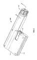
- an infusion pump system 10can include a pump device 100 and a controller device 200 that communicates with the pump device 100 .
- the pump device 100in this embodiment includes a housing structure 110 that defines a cavity 116 in which a fluid cartridge 120 can be received.
- the pump device 100also can include a cap device 130 to retain the fluid cartridge 120 in the cavity 116 of the housing structure 110 .
- the pump device 100can include a drive system that advances a plunger 125 in the fluid cartridge 120 so as to dispense fluid therefrom. As described in more detail below in connection with FIGS.
- some embodiments of the pump device 100can be advantageously equipped with a water-resistant, air-venting gasket assembly such as an air-transmissible gasket 132 in combination with a ring seal 134 .
- the air-transmissible gasket 132can facilitate equalization of air pressure between a proximal region external to the pump P e and a region internal to the pump P i .
- the air-transmissible gasket 132 and ring seal 134can also comprise materials that provide a water-resistant seal.
- This type of water-resistant, air-venting gasket assemblycan prevent changes in ambient air pressure from adversely affecting the dosage amount delivered by the infusion pump system 10 , while maintaining resistance to water migration to the pump device 100 .
- the position of the air-transmissible gasket 132e.g., on the cap device 130 and proximate to the opening of the cavity 116 ) can provide improve functionality while reducing the complexity of manufacturing the pump device 100 .
- the controller device 200communicates with the pump device 100 to control the operation of the drive system.
- the controller device 200 , the pump device 100 (including the cap device 130 ), and the fluid cartridge 120are assembled together, the user can (in some embodiments) conveniently wear the infusion pump system 10 on the user's skin under clothing, in a pouch clipped at the waist (e.g., similar to a cell phone pouch), or in the user's pocket while receiving the fluid dispensed from the pump device 100 .
- the controller device 200may be configured as a reusable component that provides electronics and a user interface to control the operation of the pump device 100 .
- the pump device 100can be a disposable component that is disposed of after a single use.
- the pump device 100can be a “one time use” component that is thrown away after the fluid cartridge 120 therein is exhausted. Thereafter, the user can removably attach a new pump device 100 ′ (having a new medicine cartridge 120 ′) to the reusable controller device 200 for the dispensation of fluid from a new fluid cartridge 120 ′. Accordingly, the user is permitted to reuse the controller device 200 (which may include complex or valuable electronics, as well as a rechargeable battery) while disposing of the relatively low-cost pump device 100 after each use.
- a pump system 10can provide enhanced user safety as a new pump device 100 ′ (and drive system therein) is employed with each new fluid cartridge 120 ′.
- the pump device 100is configured to removably attach to the controller device 200 in a manner that provides a secure fitting, an overall compact size, and a reliable electrical connection that is resistant to water migration.
- the controller device 200can include a housing 210 having a number of features that mate with complementary features of the pump housing 110 .
- the controller device 200can removably attach with the pump device 100 in a generally side-by-side configuration.
- the compact sizepermits the infusion pump system 10 to be discrete and portable (as described below in connection with FIG. 3 ).
- at least one of the pump device 100 or the controller device 200can include a release member that facilitates an easy-to-use detachment and replacement process.
- the pump system 10can be a medical infusion pump system that is configured to controllably dispense a medicine from the cartridge 120 .
- the fluid cartridge 120can contain a medicine 126 to be infused into the tissue or vasculature of a targeted individual, such as a human or animal patient.
- the pump device 100can be adapted to receive a medicine cartridge 120 in the form of a carpule that is preloaded with insulin or another medicine for use in the treatment of Diabetes (e.g., Byetta®, Symlin®, or others).
- a medicine cartridge 120may be supplied, for example, by Eli Lilly and Co. of Indianapolis, Ind.
- the fluid cartridge 120may have other configurations.
- the fluid cartridge 120may comprise a reservoir that is integral with the pump housing structure 110 (e.g., the fluid cartridge 120 can be defined by one or more walls of the pump housing structure 110 that surround a plunger to define a reservoir in which the medicine is injected or otherwise received).
- the pump device 100can include one or more structures that interfere with the removal of the medicine cartridge 120 after the medicine cartridge 120 is inserted into the cavity 116 .
- the pump housing structure 110can include one or more retainer wings (not shown in FIG. 1 ) that at least partially extend into the cavity 116 to engage a portion of the medicine cartridge 120 when the medicine cartridge 120 is installed therein. Such a configuration may facilitate the “one-time-use” feature of the pump device 100 .
- the retainer wingscan interfere with attempts to remove the medicine cartridge 120 from the pump device 100 , thus ensuring that the pump device 100 will be discarded along with the medicine cartridge 120 after the medicine cartridge 120 is emptied, expired, or otherwise exhausted.
- the cap device 130can be configured to irreversible attach to the pump body 110 so as to cover the opening of the cavity 116 .
- a head structure of the cap device 130can be configured to turn so as to threadably engage the cap device 130 with a mating structure along an inner wall of the cavity 116 , but the head structure may prevent the cap device from turning in the reverse direction so as to disengage the threads.
- the pump device 100can operate in a tamper-resistant and safe manner because the pump device 100 can be designed with a predetermined life expectancy (e.g., the “one-time-use” feature in which the pump device is discarded after the medicine cartridge 120 is emptied, expired, or otherwise exhausted).
- the controller device 200can be removably attached to the pump device 100 so that the two components are mechanically mounted to one another in a fixed relationship. Such a mechanical mounting can form an electrical connection between the removable controller device 200 and the pump device 100 .
- the controller device 200can be in electrical communication with a portion of a drive system (not shown in FIG. 1 ) of the pump device 100 .
- the pump device 100can include a drive system that causes controlled dispensation of the medicine or other fluid from the cartridge 120 .
- the drive systemincrementally advances a piston rod (not shown in FIG. 1 ) longitudinally into the cartridge 120 so that the fluid is forced out of an output end 122 .
- a septum 121FIG.
- the cap device 130may include a penetration needle that punctures the septum 121 during attachment of the cap device to the housing structure 110 .
- the controller device 200communicates electronic control signals via a hardwire-connection (e.g., electrical contacts or the like) to the drive system or other components of the pump device 100 .
- the drive system of the pump device 100causes medicine to incrementally dispense from the medicine cartridge 120 .
- Power signalssuch as signals from the rechargeable battery 245 (refer to FIG. 6 ) of the controller device 200 and from the power source 310 (refer to FIG. 7 ) of the pump device 100 may also be passed between the controller device 200 and the pump device 100 .
- the pump device 100can include an electrical connector 118 (e.g., having conductive pads, pins, and the like) that is exposed to the controller device 200 and that mates with a complementary electrical connector (refer to connector 218 in FIG. 2 ) on the adjacent face of the controller device 200 .
- the electrical connectors 118 and 218provide the electrical communication between the control circuitry (refer, for example, to FIG. 6 ) housed in the controller device 200 and at least a portion of the drive system or other components of the pump device 100 .
- the electrical connectors 118 and 218can permit the transmission of electrical control signals to the pump device 100 and the reception of feedback signals (e.g., sensor signals) from particular components within the pump device 100 .
- the electrical connectors 118 and 218may similarly facilitate transmission of one or more power signals from the rechargeable battery pack 245 to the pump device 100 , where the signals may be used to provide power to components of the pump device 100 , or to transmit one or more power signals from the power source 310 to the controller device, where the signals may be used to charge the rechargeable battery 245 or to power components of the controller device 200 .
- the controller device 200can include a user interface 220 that permits a user to monitor the operation of the pump device 100 .
- the user interface 220can include a display device 222 and one or more user-selectable buttons (e.g., several buttons 224 are shown in the embodiment of FIG. 1 ).
- the display device 222can include an active area in which numerals, text, symbols, images, or a combination thereof can be displayed.
- the display device 222can be used to communicate a number of settings or menu options for the infusion pump system 10 .
- the usermay press one or more of the buttons to shuffle through a number of menus or program screens that show particular settings and data (e.g., review data that shows the medicine dispensing rate, the total amount of medicine dispensed in a given time period, the amount of medicine scheduled to be dispensed at a particular time or date, the approximate amount of medicine remaining in the cartridge 120 , or the like).
- the usercan adjust the settings or otherwise program the controller device 200 by pressing one or more buttons of the user interface 220 .
- the usermay press one or more of the buttons to change the dispensation rate of insulin or to request that a bolus of insulin be dispensed immediately or at a scheduled, later time.
- the display device 222may also be used to communicate information regarding remaining battery life.
- the userwhen the controller device 200 is connected to the pump device 100 , the user can be provided with the opportunity to readily monitor the infusion pump operation by simply viewing the user interface 220 of the controller device 200 connected to the pump device 100 .
- Such monitoring capabilitiesmay provide comfort to a user who may have urgent questions about the current operation of the pump device 100 .
- there may be no need for the user to carry and operate a separate module to monitor the operation of the pump device 100thereby simplifying the monitoring process and reducing the number of devices that must be carried by the user.
- the usercan readily operate the user interface 220 of the controller device 200 , which is removably attached to the pump device 100 , without the requirement of locating and operating a separate monitoring module.
- the controller device 200can be removably attached to the pump device 100 in a side-by-side arrangement.
- the pump device 100may be moved in a longitudinal direction (e.g., refer to direction 219 in FIG. 4 ) toward the controller device 200 until the complementary features connect and secure the separate components in the side-by-side arrangement.
- the controller device 200can include a controller housing structure 210 having a number of features that are configured to mate with complementary features of the pump housing structure 110 so as to form a releasable mechanical connection.
- the pump housing structure 110can include a barrel 111 that mates with a complementary barrel channel 211 of the controller housing 210 .
- the pump device 100 and the controller device 200can be mounted to one another so that the assembled system 10 is resistant to water migration both into the pump housing structure 110 and the controller housing structure 210 .
- Such a configurationcan also provide water-resistant protection for the electrical connection between the pump device 100 and the controller device 200 .
- the sensitive internal components in the controller device 200 and the pump device 100can be reliably protected from water migration if the user encounters water (e.g., rain, incidental splashing, and the like) while using the pump system 10 .
- the infusion pump system 10can be configured to be portable and can be wearable and concealable.
- a usercan conveniently wear the infusion pump system 10 on the user's skin (e.g., skin adhesive) underneath the user's clothing or carry the pump device 100 in the user's pocket (or other portable location) while receiving the medicine dispensed from the pump device 100 .
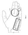
- the pump system 10is shown in FIG. 3 as being held in a user's hand 5 so as to illustrate an exemplary size of the system 10 in accordance with some embodiments.
- the infusion pump system 10is compact so that the user can wear the portable infusion pump system 10 (e.g., in the user's pocket, connected to a belt clip, adhered to the user's skin, or the like) without the need for carrying and operating a separate module.
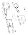
- the cap device 130 of the pump device 100can be configured to mate with an infusion set 146 .
- the infusion set 146can be a tubing system that connects the infusion pump system 10 to the tissue or vasculature of the user (e.g., to deliver medicine into the tissue or vasculature under the user's skin).
- the infusion set 146can include a flexible tube 147 that extends from the pump device 100 to a subcutaneous cannula 149 that may be retained by a skin adhesive patch (not shown) that secures the subcutaneous cannula 149 to the infusion site.
- the skin adhesive patchcan retain the infusion cannula 149 in fluid communication with the tissue or vasculature of the patient so that the medicine dispensed through the tube 147 passes through the cannula 149 and into the user's body.
- the cap device 130can provide fluid communication between the output end 122 ( FIG. 1 ) of the medicine cartridge 120 and the tube 147 of the infusion set 146 .
- the infusion pump system 10can be pocket-sized so that the pump device 100 and controller device 200 can be worn in the user's pocket or in another portion of the user's clothing.
- the usermay desire to wear the pump system 10 in a more discrete manner. Accordingly, the user can pass the tube 147 from the pocket, under the user's clothing, and to the infusion site where the adhesive patch can be positioned.
- the pump system 10can be used to deliver medicine to the tissues or vasculature of the user in a portable, concealable, and discrete manner.
- the infusion pump system 10can be configured to adhere to the user's skin directly at the location in which the skin is penetrated for medicine infusion.
- a rear surface 102 ( FIG. 2 ) of the pump device 100can include a skin adhesive patch so that the pump device 100 can be physically adhered to the skin of the user at a particular location.
- the cap device 130can have a configuration in which medicine passes directly from the cap device 130 into an infusion cannula 149 that is penetrated into the user's skin.
- the usercan temporarily detach the controller device 200 (while the pump device 100 remains adhered to the skin) so as to view and interact with the user interface 220 .
- the infusion pump system 10can be operated such that the pump device 100 is a disposable, non-reusable component while the controller device 200 is a reusable component.
- the pump device 100may be configured as a “one-time-use” device that is discarded after the medicine cartridge is emptied, expired, or otherwise exhausted.
- the pump device 100can be designed to have an expected operational life of about 1 day to about 30 days, about 1 day to about 20 days, about 1 to about 14 days, or about 1 day to about 7 days—depending on the volume of medicine in the cartridge 120 , the dispensation patterns that are selected for the individual user, and other factors.
- a medicine cartridge 120 containing insulincan have an expected usage life of about 7 days after the cartridge is removed from a refrigerated state and the septum 121 is punctured.
- the dispensation pattern selected by the usercan cause the insulin to be emptied from the medicine cartridge 120 before the 7-day period. If the insulin is not emptied from the medicine cartridge 120 after the 7-day period, the remaining insulin can become expired sometime thereafter. In either case, the pump device 100 and the medicine cartridge 120 therein can be collectively discarded after exhaustion of the medicine cartridge 120 (e.g., after being emptied, expired, or otherwise not available for use).
- the controller device 200may be reused with subsequent new pump devices 100 ′ and new medicine cartridges 120 ′.
- the control circuitry, the user interface components, the rechargeable battery pack 245 , and other components that may have relatively higher manufacturing costscan be reused over a longer period of time.
- the controller device 200can be designed to have an expected operational life of about 1 year to about 7 years, about 2 years to about 6 years, or about 3 years to about 5 years—depending on a number of factors including the usage conditions for the individual user.
- the usercan be permitted to reuse the controller device 200 (which can include complex or valuable electronics, and a rechargeable battery pack) while disposing of the relatively low-cost pump device 100 after each use.
- Such a pump system 10can provide enhanced user safety as a new pump device 100 ′ (and drive system therein) is employed with each new medicine cartridge 120 ′.
- the same controller device 200can be reused with a new pump device 100 ′ having a new medicine cartridge 120 ′ retained therein, and the previously used pump device 100 , including the exhausted medicine cartridge, can be discarded in a discard bin 20 .
- the new pump device 100 ′( FIG. 4 ) can have a similar appearance, form factor, and operation as the previously used pump device 100 , and thus the new pump device 100 ′ can be readily attached to the controller device 200 for controlled dispensation of medicine from the new medicine cartridge 120 ′.
- the usercan prepare the new pump device 100 ′ for use with the controller device 200 .
- the usermay insert the new medicine cartridge 120 ′ in the cavity 116 of the new pump device 100 ′ and then join the cap device 130 to the pump housing to retain the new medicine cartridge 120 ′ therein (refer, for example, to FIG. 1 ).
- the tubing 147 of the infusion set 146is not shown in FIG. 4 , it should be understood that the tubing 147 can be attached to the cap device 130 prior to the cap device 130 being joined with the housing 110 .
- a new infusion set 146can be connected to the cap device 130 so that the tubing 147 can be primed (e.g., a selected function of the pump device 100 controlled by the controller device 200 ) before attaching the cannula's adhesive patch to the user's skin.
- the new medicine cartridge 120 ′may be filled with medicine such that the plunger 125 is not viewable through the barrel 111 .
- the new pump device 100 ′can be removably attached to the controller device 200 to assemble into the infusion pump system 10 for delivery of medicine to the user.
- the guided motion in the longitudinal direction 219provides the user with a convenient “one-movement” process to attach the pump device 100 ′ and the controller device 200 .
- the usercan readily slide the pump device 100 ′ and the controller device 200 toward one another in a single movement (e.g., in the longitudinal direction 219 ) that causes both a physical connection and an electrical connection.
- the infusion pump system 10can permit users to readily join the pump device 100 ′ and the controller device 200 without compound or otherwise difficult hand movements—a feature that can be particularly beneficial to child users or to elderly users.
- the controller device 200houses a number of components that can be reused with a series of successive pump devices 100 .
- the controller device 200can include controller circuitry 240 and a rechargeable battery pack 245 , each arranged in the controller housing 210 .
- rechargeable battery pack 245may provide electrical energy to components of controller circuitry 240 , other components of the controller device (e.g., a display device 222 and other user interface components, sensors, or the like), or to components of the pump device 100 .
- Controller circuitry 240may be configured to communicate control or power signals to the drive system of the pump device 100 , or to receive power or feedback signals from the pump device 100 .
- the user interface 220 of the controller device 200can include input components and/or output components that are electrically connected to the controller circuitry 240 .
- the user interface 220can include the display device 222 having an active area that outputs information to a user and buttons 224 that the user can use to provide input.
- the display device 222can be used to communicate a number of settings or menu options for the infusion pump system 10 .
- the controller circuitry 240can receive input commands from a user's button selections and thereby cause the display device 222 to output a number of menus or program screens that show particular settings and data (e.g., review data that shows the medicine dispensing rate, the total amount of medicine dispensed in a given time period, the amount of medicine scheduled to be dispensed at a particular time or date, the approximate amount of medicine remaining the cartridge 120 , the amount of battery life remaining, or the like).
- the controller circuitry 240can be programmable to cause the controller circuitry 240 to change any one of a number of settings for the infusion pump system 10 .
- the usermay provide one or more instructions to adjust a number of settings for the operation of the infusion pump system 10 .
- Such settingsmay be stored in one or more memory devices arranged in the controller circuitry 240 .
- the controller circuitry 240can include a cable connector (e.g., a USB connection port or another data cable port) that is accessible on an external portion of the controller housing 210 .
- a cablecan be connected to the controller circuitry 240 to upload data or program settings to the controller circuitry or to download data from the controller circuitry.
- datacan also provide recharging power.
- the pump device 100can include a drive system 300 that is controlled by the controller device 200 .
- the drive system 300can incrementally dispense fluid in a controlled manner from cartridge 120 inserted into the pump device 100 .
- the pump device 100may include a connector circuit 318 to facilitate the transfer of signals to and from the electrical connector 118 .
- the connector circuit 318 in the pump device 100may include a memory device that can store data regarding the pump device 100 and its operational history.
- the electrical connector 118 of the pump device 100can mate with the connector 218 ( FIG. 2 ) of the controller device 200 so that electrical communication can occur between the pump device 100 and the controller device 200 .
- the connector circuit 318can operate as a passageway to transmit electrical control signals from the controller circuitry 240 of the controller device 200 to the drive system 300 .
- the connector circuit 318can also operate as a passageway for the electrical power from a power source 310 housed in the pump device 300 to pass to the controller device 200 for recharging of the rechargeable battery 245 .
- the connector circuit 318can operate as a passageway for feedback signals from the drive system 300 to the controller circuitry 240 of the controller device 200 .
- the pump device 100houses the drive system 300 and the power source 310 .
- the power source 310may comprise an alkaline battery cell, such as a 1.5 Volt “AAA” alkaline battery cell, which is contained in a dedicated space of the pump housing structure 110 .
- the power source 310may be capable of transmitting electrical energy to the controller device 200 when the pump device 100 is attached to the controller device 200 , via connectors 118 and 218 as described above.
- the power source 310may be used to charge the rechargeable battery pack 245 when the pump device 100 is attached to the controller device 200 .
- the power source 310is used to provide energy to the drive system 300 of the pump device 100 , and also to electronic components of the controller device 200 .
- the power source 310may provide the energy to power all aspects of the infusion pump system 10 .
- the rechargeable battery 245 housed in the controller 200may provide the energy to power all aspects of the infusion pump system 10 .
- the rechargeable battery 245 and the power source 310may each be responsible for powering particular aspects of the infusion pump system 10 .
- the rechargeable battery 245may provide the energy to supplement the energy provided by the power source 310 to power aspects of the infusion pump system.
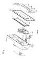
- the drive system 300may include a number of components, such as an electrically powered actuator (e.g., reversible motor 320 or the like), a drive wheel 360 , a bearing 365 , a flexible piston rod 370 , a piston rod guide 363 , and a plunger engagement device 375 .
- the reversible motor 320drives a gear system (not shown in FIG. 7 ) to cause the rotation of the drive wheel 360 that is coupled with the bearing 365 .
- the drive wheel 360may include a central aperture with an internal thread pattern, which mates with an external thread pattern on the flexible piston rod 370 .
- the interface of the threaded portions of the drive wheel 360 and flexible piston rod 370may be used to transmit force from the drive wheel to the piston rod 370 .
- the drive wheel 360is the driver while the flexible piston rod 370 is the driven member.
- the rotation of the drive wheel 360can drive the flexible piston rod 370 forward in a linear longitudinal direction.
- the flexible piston rod 370can, in turn, contact and drive forward a plunger 125 in the fluid cartridge 120 so as to dispense fluid therefrom.
- some embodiments of the pump device 100can be equipped with the water-resistant, air-venting gasket assembly including the air-transmissible gasket 132 in combination with the ring seal 134 .
- the water-resistant, air-venting gasket assemblyis secured to the cap device 130 and positioned to provide a water resistant seal along the interface between the cap device 130 and the pump housing 110 .
- the pump housing 110defines the cavity 116 configured to slidably receive the fluid cartridge 120 .
- the air-transmissible gasket 132 and ring seal 134are arranged so that interior air pressure P i in the cavity 116 can reach approximate equilibrium with the exterior air pressure P e even though the seal resists water migration into the cavity 116 .
- the air-transmissible gasket 132 and the ring seal 134can both have a generally circular shape with a central aperture therethrough.
- the air-transmissible gasket 132may comprise a generally flat disc-shaped structure that is configured to abut with the ring seal.
- the air-transmissible gasket 132can comprise a first major surface 133 that is generally planar, a second, opposite major surface 135 that is generally planner, and an inner rim 138 that defines a central aperture therethrough.
- the first major surface 133 of the air-transmissible gasket 132can be sized so that it entirely abuts with a first major surface 137 of the ring seal 134 .
- the ring seal 134is not necessarily air-transmissible and thereby may prevent air transmission in a path exiting from or passing into the first major surface 133 of the air-transmissible gasket 132
- the air-transmissible gasket 132may provide air transmission in a path exiting from or passing into the surface of the inner rim 138 of the air-transmissible gasket 132 (as described below in connection with FIG. 9 ).
- the ring seal 134may comprise a generally “L-shaped” cross-section so that an inner rim 139 of the ring seal 134 is configured to be retained in an annular seat 136 ( FIG. 9 ) of the cap device 130 , as described in more detail below.
- the inner rim 138 of the air-transmissible gasket 132 and the inner rim 139 of the ring seal 134can be substantially similar in size, with both of them being generally axially aligned and being generally aligned with the cavity 116 of the pump housing (when the cap device 130 is attached to the pump housing 110 ).
- such a water-resistant seal between the cap device 130 and the pump housing 110provides a functional benefit in that it protects sensitive internal components in the pump device 100 from damage by water migration in the event that the user encounters water (e.g. rain, incidental splashing, and the like).
- air-transmissible gasket 132 and ring seal 134can be constructed from materials that are generally resistant to liquid penetration. Further, at least one of the air-transmissible gasket 132 and ring seal 134 can preferably be sufficiently compliant to enable a tight and conformant physical seal between the cap device 130 and the pump housing 110 .
- the ring seal 134can comprise a pliable elastomeric material such as silicone, nitrile rubber, natural rubber, polyurethane, and neoprene. Those materials can enable ring seal 134 to be compliant, pliable, and to provide a water-resistant seal.
- a pliable elastomeric materialsuch as silicone, nitrile rubber, natural rubber, polyurethane, and neoprene. Those materials can enable ring seal 134 to be compliant, pliable, and to provide a water-resistant seal.
- the air-transmissible gasket 132can comprise a material that is different from the elastomeric material of the ring seal 134 .
- the air-transmissible gasket 132can be configured to allow the passage of air between the internal and external regions of the pump device 100 while also resisting water migration into the pump cavity 116 .
- the air-transmissible gasket 132may comprise a hydrophobic material (e.g., a material that permits air to pass therethrough while resisting the passage of water or other liquids from doing so).
- the air-transmissible gasket 132may comprise a hydrophobic material such as GORE-TEX® (W.L. Gore & Associates, Inc. of Newark, Del.), POREX® (Porex Corporation of Fairburn, Ga.), PTFE, or HDPE.
- This air-venting capability of the air-transmissible gasket 132can serve to prevent changes in ambient air pressure from potentially adversely affecting the dosage delivered by the infusion pump system 10 .
- a user of the infusion pump system 10may take an airplane flight during which the air pressure external to the pump system P e will be reduced as compared to the air pressure on land. If the air pressure within the pump housing P i is not allowed to vent, it will remain higher than the external pressure P e . That pressure differential could result in a pressure being exerted on the plunger 125 , which in turn could result in an inadvertent dispensation of fluid from the fluid cartridge 120 .
- the infusion pump system 10can benefit from a system which permits an equalization of an air pressure differential between the regions external to the pump P e and internal to the pump P i .
- the air-transmissible gasket 132can function to provide such equalization of air pressures.
- the water-resistant, air-venting gasket assemblycan be provided by air-transmissible gasket 132 and ring seal 134 located between the cap device 130 and the pump housing 110 , with the gasket 132 and seal 134 being compressed between the pump housing 116 and the cap device 130 .
- the air-transmissible gasket 132 and ring seal 134can be physically seated and retained in a groove 136 ( FIG. 9 ) located on the outer barrel of cap device 130 . With the air-transmissible gasket 132 and ring seal 134 seated in groove 136 , the water-resistant, air-venting gasket assembly can be retained by the cap device 130 even before it is attached to the pump housing 110 .
- the seating of the air-transmissible gasket 132 and ring seal 134 in the groove 136facilitates proper positioning and functionality of the water-resistant, air-venting seal during attachment of the cap device 130 with the pump housing 110 , which can thereafter be maintained during the life of the pump device 100 (e.g., until exhaustion of the medicine cartridge 120 or other such events).
- the air-transmissible gasket 132 and ring seal 134can be maintained in physical contact with each other.
- the first major surface 133 of air-transmissible gasket 132is in contact with first major surface 137 of the ring seal 134 (as previously described in connection with FIG. 7 ).
- the path for air transmission through air-transmissible gasket 132can be through the smaller surface at the inner rim 138 ( FIG. 7 ) rather than through the first major surface 137 (which abuts the elastomeric material of the ring seal 134 ).
- Such an air path through air-transmissible gasket 132can enable an air flow for the equalization of an air pressure differential between the pressure in a region external to the pump P e and internal to the pump P i .
- the air pathcan pass from the interior of the cavity 116 , along the annular surface of the seat 136 , through the inner rim 138 of the gasket 132 , through the outer periphery of the gasket 132 , and out through a gap 131 between the pump housing 110 and an opposing face of the cap device 130 .
- the gap 131can be smaller than what is depicted in FIG.
- the ring seal 134can be in contact with the air-transmissible gasket 132 on one side and the rim of the cavity 116 of the housing structure 110 on the other side. Thus, when the cap device 130 is threaded into engagement with the pump housing 110 , the ring seal 134 is subject to axial compression between the pump housing 110 and the cap device 130 .
- This example configuration of air-transmissible gasket 132 and ring seal 134can provide the aforementioned water-resistant, air-venting capabilities during use of the pump device 100 .
- FIG. 10illustrates a process 400 by which a medicine infusion pump device can provide pressure equalization between an interior pressure (e.g., inside the pump device) and the ambient pressure.
- This process 400can be implemented, for example, by an infusion pump system like the pump system 10 described in connection with FIGS. 1-9 .
- the pump system 10can realize a state of air pressure equilibrium between a space that is external to the pump system 10 and a space that is internal to the pump system 10 even when the pump system 10 is exposed to a gradient in ambient pressure.
- the infusion pump pressure equilibrium process 400includes operation 410 of slidably receiving a medicine cartridge through a cavity opening of an infusion pump housing and into an interior space of the infusion pump housing.
- the medicine cartridge 120is slidably received in the cavity 116 of the pump housing 110 .
- the process 400may also include the operation 420 of receiving a cap device into attachment with the infusion pump housing so that an air-transmissible gasket of the cap device is positioned proximate to the cavity opening defined by the infusion pump housing.
- the cap device 130is received into attachment with the pump housing 110 so that the air-transmissible gasket 132 is proximate to the opening of the cavity 116 , which (as previously described) permits air transmission between the interior and exterior regions of the pump system 10 in the event of an air pressure differential between those two regions.
- the air-transmissible gasketis maintained in a position between the cap device and a rim of the cavity opening of the infusion pump housing.
- Such positioning of the air-transmissible gasketis configured to permit a water-resistant seal with air-venting capabilities.
- the air-transmissible gasket 132is part of the water-resistant, air-venting gasket assembly arranged along an interface of the cap device 130 and the pump housing 110 .
- the air-transmissible gasket 132 in combination with the ring seal 134can provide the air-venting capabilities while also protecting against water migration into the interior of the pump device 100 .
- the process 400may also include the operation 440 of equalizing pressures between the interior space of the infusion pump housing and an external space proximate to the infusion pump housing in response to a change in ambient pressure.
- the infusion pump system 10may be exposed to an ambient pressure change.
- the pump system 10can be configured to equalize the internal air pressure P i in the cavity 116 with the ambient air pressure P e via the air-transmissible gasket 132 . For example, if a user takes the pump system 10 onto an airplane the air pressure in the cabin of the airplane while in-flight will be lower than the air pressure on land prior to take-off.
- the higher air pressure in the interior of pump systemwill be vented through an air-transmissible gasket so that the pump system's interior air pressure will be reduced to equal the air pressure in the cabin of the airplane. In this manner, the potentially adverse effects of a pressure gradient between the interior and exterior of an infusion pump system 10 can be mitigated.
Landscapes
- Health & Medical Sciences (AREA)
- Vascular Medicine (AREA)
- Engineering & Computer Science (AREA)
- Anesthesiology (AREA)
- Biomedical Technology (AREA)
- Heart & Thoracic Surgery (AREA)
- Hematology (AREA)
- Life Sciences & Earth Sciences (AREA)
- Animal Behavior & Ethology (AREA)
- General Health & Medical Sciences (AREA)
- Public Health (AREA)
- Veterinary Medicine (AREA)
- Infusion, Injection, And Reservoir Apparatuses (AREA)
- External Artificial Organs (AREA)
Abstract
Description
Claims (20)
Priority Applications (4)
| Application Number | Priority Date | Filing Date | Title |
|---|---|---|---|
| US13/553,921US8454562B1 (en) | 2012-07-20 | 2012-07-20 | Infusion pump system and method |
| US13/886,589US9517300B2 (en) | 2012-07-20 | 2013-05-03 | Pump system and method |
| PCT/US2013/051273WO2014015257A1 (en) | 2012-07-20 | 2013-07-19 | Pump system and method |
| EP13820259.3AEP2874680B1 (en) | 2012-07-20 | 2013-07-19 | Pump system and method |
Applications Claiming Priority (1)
| Application Number | Priority Date | Filing Date | Title |
|---|---|---|---|
| US13/553,921US8454562B1 (en) | 2012-07-20 | 2012-07-20 | Infusion pump system and method |
Related Child Applications (1)
| Application Number | Title | Priority Date | Filing Date |
|---|---|---|---|
| US13/886,589ContinuationUS9517300B2 (en) | 2012-07-20 | 2013-05-03 | Pump system and method |
Publications (1)
| Publication Number | Publication Date |
|---|---|
| US8454562B1true US8454562B1 (en) | 2013-06-04 |
Family
ID=48484234
Family Applications (2)
| Application Number | Title | Priority Date | Filing Date |
|---|---|---|---|
| US13/553,921ActiveUS8454562B1 (en) | 2012-07-20 | 2012-07-20 | Infusion pump system and method |
| US13/886,589Active2033-07-07US9517300B2 (en) | 2012-07-20 | 2013-05-03 | Pump system and method |
Family Applications After (1)
| Application Number | Title | Priority Date | Filing Date |
|---|---|---|---|
| US13/886,589Active2033-07-07US9517300B2 (en) | 2012-07-20 | 2013-05-03 | Pump system and method |
Country Status (3)
| Country | Link |
|---|---|
| US (2) | US8454562B1 (en) |
| EP (1) | EP2874680B1 (en) |
| WO (1) | WO2014015257A1 (en) |
Cited By (19)
| Publication number | Priority date | Publication date | Assignee | Title |
|---|---|---|---|---|
| US20130076518A1 (en)* | 2011-09-27 | 2013-03-28 | Animas Corporation | Water resistant drug infusion housing with pressure differential sensor |
| US20140025008A1 (en)* | 2012-07-20 | 2014-01-23 | Asante Solutions, Inc. | Pump System and Method |
| US8758323B2 (en) | 2009-07-30 | 2014-06-24 | Tandem Diabetes Care, Inc. | Infusion pump system with disposable cartridge having pressure venting and pressure feedback |
| US20140221930A1 (en)* | 2012-09-27 | 2014-08-07 | Roche Diagnostics International Ag | Venting Device for Use in Ambulatory Infusion System |
| US20140358111A1 (en)* | 2013-06-03 | 2014-12-04 | Asante Solutions, Inc. | Infusion Pump System and Method |
| WO2014197389A1 (en) | 2013-06-03 | 2014-12-11 | Asante Solutions, Inc. | Infusion pump system and method |
| US9555186B2 (en) | 2012-06-05 | 2017-01-31 | Tandem Diabetes Care, Inc. | Infusion pump system with disposable cartridge having pressure venting and pressure feedback |
| US9962486B2 (en) | 2013-03-14 | 2018-05-08 | Tandem Diabetes Care, Inc. | System and method for detecting occlusions in an infusion pump |
| US9987428B2 (en) | 2011-10-14 | 2018-06-05 | Amgen Inc. | Injector and method of assembly |
| USD829434S1 (en)* | 2016-04-29 | 2018-10-02 | Csl Behring Recombinant Facility Ag | Syringe pump housing |
| USD831194S1 (en)* | 2016-04-29 | 2018-10-16 | Csl Behring Recombinant Facility Ag | Syringe pump housing |
| USD831820S1 (en)* | 2016-04-29 | 2018-10-23 | Csl Behring Recombinant Facility Ag | Syringe pump housing |
| USD831821S1 (en)* | 2016-04-29 | 2018-10-23 | Csl Behring Recombinant Facility Ag | Syringe pump housing |
| US10258736B2 (en) | 2012-05-17 | 2019-04-16 | Tandem Diabetes Care, Inc. | Systems including vial adapter for fluid transfer |
| US10279106B1 (en) | 2014-05-08 | 2019-05-07 | Tandem Diabetes Care, Inc. | Insulin patch pump |
| US10850037B2 (en) | 2013-03-22 | 2020-12-01 | Amgen Inc. | Injector and method of assembly |
| US11097055B2 (en) | 2013-10-24 | 2021-08-24 | Amgen Inc. | Injector and method of assembly |
| US20220347393A1 (en)* | 2019-09-02 | 2022-11-03 | Shl Medical Ag | Administration mechanism for a medicament delivery device |
| US11547811B2 (en)* | 2016-04-27 | 2023-01-10 | Medtronic Minimed, Inc. | Set connector systems for venting a fluid reservoir |
Families Citing this family (3)
| Publication number | Priority date | Publication date | Assignee | Title |
|---|---|---|---|---|
| EP3254714B1 (en)* | 2016-06-08 | 2021-07-28 | SHL Medical AG | Device and system for dispensing a fluid under aseptic conditions |
| CN111388795A (en)* | 2020-03-24 | 2020-07-10 | 首都医科大学宣武医院 | A mobile medical device suitable for stroke patients |
| EP4506024A1 (en)* | 2022-04-07 | 2025-02-12 | MicroTech Medical (Hangzhou) Co., Ltd. | Infusion device, assembly method therefor, and use thereof |
Citations (177)
| Publication number | Priority date | Publication date | Assignee | Title |
|---|---|---|---|---|
| US669668A (en) | 1900-11-17 | 1901-03-12 | David A Sprinkle | Wood pulley. |
| GB747701A (en) | 1953-12-16 | 1956-04-11 | Lines Bros Ltd | Improvements in apparatus for controlling movements of model ships or other toys |
| US4373527A (en) | 1979-04-27 | 1983-02-15 | The Johns Hopkins University | Implantable, programmable medication infusion system |
| EP0062974B1 (en) | 1981-04-10 | 1986-07-30 | Parker Hannifin Corporation | Medication injection device |
| US4652260A (en) | 1985-03-11 | 1987-03-24 | Strato Medical Corporation | Infusion device |
| US4668220A (en) | 1984-10-26 | 1987-05-26 | Infors Gmbh | Infusion pump |
| GB2218831A (en) | 1988-05-17 | 1989-11-22 | Mark John Newland | Personal medical apparatus |
| US4902278A (en) | 1987-02-18 | 1990-02-20 | Ivac Corporation | Fluid delivery micropump |
| FR2585252B1 (en) | 1985-07-26 | 1990-06-15 | Gazuit Ste Nle Electronique | SYRINGE DRIVER |
| EP0275213B1 (en) | 1987-01-16 | 1992-03-18 | Pacesetter Infusion Ltd. | Medication infusion system |
| US5176632A (en) | 1989-05-29 | 1993-01-05 | Ampliscientifica S.R.L. | Wearable artificial pancreas |
| EP0580723B1 (en) | 1991-04-18 | 1995-10-25 | Novo Nordisk A/S | Infuser |
| EP0496141B1 (en) | 1991-01-22 | 1997-04-02 | Eli Lilly And Company | Multiple dose injection pen |
| US5672167A (en) | 1990-05-21 | 1997-09-30 | Recordati Corporation | Controlled release osmotic pump |
| US5718562A (en) | 1995-11-02 | 1998-02-17 | Abbott Laboratories | Interface module for use with an NCT-based pumping mechanism and NCT-based cassette |
| US5800420A (en) | 1994-11-04 | 1998-09-01 | Elan Medical Technologies Limited | Analyte-controlled liquid delivery device and analyte monitor |
| US6127061A (en) | 1999-01-26 | 2000-10-03 | High-Density Energy, Inc. | Catalytic air cathode for air-metal batteries |
| EP0612004B2 (en) | 1993-01-15 | 2000-10-04 | Alaris Medical Systems, Inc. | Configuration control system for configuring multiple biomedical devices |
| JP2000513974A (en) | 1996-07-05 | 2000-10-24 | ノボ ノルディスク アクティーゼルスカブ | Flexible piston rod |
| EP1045146A3 (en) | 1999-04-14 | 2001-03-21 | Clemens Micheler | Medical dosing pump |
| US6231540B1 (en) | 1997-07-14 | 2001-05-15 | Novo Nordisk A/S | Injection member |
| US6248090B1 (en) | 1996-02-23 | 2001-06-19 | Novo Nordisk A/S | Syringe with electronic representation of parameters |
| US6248067B1 (en) | 1999-02-05 | 2001-06-19 | Minimed Inc. | Analyte sensor and holter-type monitor system and method of using the same |
| US6248093B1 (en) | 1998-10-29 | 2001-06-19 | Minimed Inc. | Compact pump drive system |
| US6277098B1 (en) | 1996-03-12 | 2001-08-21 | Novo Nordisk A/S | Injection device with electronic presentation of set doses |
| EP1136698A1 (en) | 2000-03-17 | 2001-09-26 | Seiko Epson Corporation | Temperature difference drive unit, and electric device, timepiece and light electrical appliance having the same |
| US6302855B1 (en) | 1998-05-20 | 2001-10-16 | Novo Nordisk A/S | Medical apparatus for use by a patient for medical self treatment of diabetes |
| US20010041869A1 (en) | 2000-03-23 | 2001-11-15 | Causey James D. | Control tabs for infusion devices and methods of using the same |
| US20010056262A1 (en) | 1998-05-21 | 2001-12-27 | Oz Cabiri | Adhesive system for medical devices |
| US20020004651A1 (en) | 2000-04-13 | 2002-01-10 | Henrik Ljunggreen | Drug delivery device provided with a one-way mechanism |
| US20020007154A1 (en) | 2000-05-04 | 2002-01-17 | Steffen Hansen | Injection device, a preassembled dose setting and injection mechanism for an injection device, and a method of assembling an injection device |
| US20020016568A1 (en) | 2000-01-21 | 2002-02-07 | Lebel Ronald J. | Microprocessor controlled ambulatory medical apparatus with hand held communication device |
| US20020032402A1 (en) | 1997-08-15 | 2002-03-14 | Daoud Adib G. | System and method for high pressure delivery of gas-supersaturated fluids |
| US20020040208A1 (en) | 2000-10-04 | 2002-04-04 | Flaherty J. Christopher | Data collection assembly for patient infusion system |
| US6375638B2 (en) | 1999-02-12 | 2002-04-23 | Medtronic Minimed, Inc. | Incremental motion pump mechanisms powered by shape memory alloy wire or the like |
| US6379339B1 (en) | 1996-09-13 | 2002-04-30 | Nova Nordisk A/S | Syringe |
| US6381496B1 (en) | 1999-10-01 | 2002-04-30 | Advanced Bionics Corporation | Parameter context switching for an implanted device |
| EP0721358B1 (en) | 1993-09-27 | 2002-05-08 | Novo Nordisk A/S | Displacement system for controlled infusion of a liquid |
| US6404098B1 (en) | 1999-04-15 | 2002-06-11 | Sony Corporation | Drive unit using shape memory alloy |
| US20020091358A1 (en) | 2000-10-05 | 2002-07-11 | Klitmose Lars Peter | Medication delivery device with bended piston rod |
| US20020126036A1 (en) | 2000-12-21 | 2002-09-12 | Flaherty J. Christopher | Medical apparatus remote control and method |
| US6461331B1 (en) | 1999-05-21 | 2002-10-08 | Minimed Inc. | Device and method for infusion of small molecule insulin mimetic materials |
| US20020156462A1 (en) | 2001-04-18 | 2002-10-24 | Stultz Mark R. | Programmable implantable pump with accessory reservoirs and multiple independent lumen catheter |
| US6474219B2 (en) | 2000-03-24 | 2002-11-05 | Novo Nordisk A/S | Flexible piston rod |
| US6485461B1 (en) | 2000-04-04 | 2002-11-26 | Insulet, Inc. | Disposable infusion device |
| US6491684B1 (en) | 2001-05-22 | 2002-12-10 | Durect Corporation | Fluid delivery device having a water generating electrochemical/chemical pump and associated method |
| US6508788B2 (en) | 2000-10-27 | 2003-01-21 | Novo Nordisk A/S | Medication delivery device with telescopic piston rod |
| US6524280B2 (en) | 2000-01-28 | 2003-02-25 | Noro Nordisk A/S | Dose setting limiter |
| US6533183B2 (en) | 2000-05-03 | 2003-03-18 | Novo Nordisk A/S | Coding of cartridges for an injection device |
| US20030055380A1 (en) | 2001-09-19 | 2003-03-20 | Flaherty J. Christopher | Plunger for patient infusion device |
| US6537268B1 (en) | 1998-06-18 | 2003-03-25 | Medtronic Minimed, Inc. | Medical infusion device with a source of controlled compliance |
| US6540672B1 (en) | 1998-12-09 | 2003-04-01 | Novo Nordisk A/S | Medical system and a method of controlling the system for use by a patient for medical self treatment |
| US6544229B1 (en) | 2000-05-01 | 2003-04-08 | Baxter International Inc | Linearly motile infusion pump |
| US6547764B2 (en) | 2000-05-31 | 2003-04-15 | Novo Nordisk A/S | Double pointed injection needle |
| US6551276B1 (en) | 1998-08-18 | 2003-04-22 | Medtronic Minimed, Inc. | External infusion device with remote programming bolus estimator and/or vibration alarm capabilities |
| US6554800B1 (en) | 2000-08-09 | 2003-04-29 | Medtronic Minimed, Inc. | Compact pump motor system and dispensing process |
| US6558320B1 (en) | 2000-01-20 | 2003-05-06 | Medtronic Minimed, Inc. | Handheld personal data assistant (PDA) with a medical device and method of using the same |
| US6558351B1 (en) | 1999-06-03 | 2003-05-06 | Medtronic Minimed, Inc. | Closed loop system for controlling insulin infusion |
| US20030088238A1 (en) | 2001-09-26 | 2003-05-08 | Poulsen Jens Ulrik | Modular drug delivery system |
| US6562011B1 (en) | 1998-07-08 | 2003-05-13 | Novo Nordisk A/S | Medication delivery device |
| US6569126B1 (en) | 1997-07-14 | 2003-05-27 | Novo Nordisk A/S | Cylinder ampoule |
| US6582404B1 (en) | 1999-09-16 | 2003-06-24 | Nna/S | Dose setting limiter |
| US6605067B1 (en) | 1998-11-20 | 2003-08-12 | Novo Nordisk A/S | Injection needle |
| US20030161744A1 (en) | 2002-02-28 | 2003-08-28 | Vilks Clinton S. | Cartridge and pump with axial loading |
| US6613019B2 (en) | 2000-07-14 | 2003-09-02 | Novo Nordisk A/S | Liquid medication delivery device and a method of delivering an intended dose |
| US20030199825A1 (en) | 2002-04-23 | 2003-10-23 | Flaherty J. Christopher | Dispenser for patient infusion device |
| US6650951B1 (en) | 2000-06-19 | 2003-11-18 | International Business Machines Corporation | Method and insulin pump for providing a forgotten bolus warning |
| US20030216683A1 (en) | 2001-11-26 | 2003-11-20 | Nili-Med Ltd. | Drug delivery device and method |
| US20030216686A1 (en) | 2002-03-08 | 2003-11-20 | Applied Diabetes Research, Inc. | Low profile, pivotal connection infusion assembly |
| US6656158B2 (en) | 2002-04-23 | 2003-12-02 | Insulet Corporation | Dispenser for patient infusion device |
| US6659980B2 (en) | 2000-03-29 | 2003-12-09 | Medtronic Minimed Inc | Methods, apparatuses, and uses for infusion pump fluid pressure and force detection |
| US6659978B1 (en) | 1999-10-04 | 2003-12-09 | Seiko Instruments Inc. | Portable dosing apparatus |
| US6663602B2 (en)* | 2000-06-16 | 2003-12-16 | Novo Nordisk A/S | Injection device |
| US6669669B2 (en) | 2001-10-12 | 2003-12-30 | Insulet Corporation | Laminated patient infusion device |
| US20040010207A1 (en) | 2002-07-15 | 2004-01-15 | Flaherty J. Christopher | Self-contained, automatic transcutaneous physiologic sensing system |
| US20040019325A1 (en) | 2002-07-29 | 2004-01-29 | Medrip Ltd. | Syringe Pump |
| US6690192B1 (en) | 2002-10-16 | 2004-02-10 | Pericom Semiconductor Corp. | Current-compensated CMOS output buffer adjusting edge rate for process, temperature, and Vcc variations |
| US6691043B2 (en) | 2001-08-28 | 2004-02-10 | Maxi-Med, Llc | Bolus calculator |
| US6692457B2 (en) | 2002-03-01 | 2004-02-17 | Insulet Corporation | Flow condition sensor assembly for patient infusion device |
| DE10236669A1 (en) | 2002-08-09 | 2004-02-19 | Korszak, Dieter | Pen for administration of insulin injections, comprising LED to display amount to be injected, acoustic repeat and timer to give visual and acoustic indications of dosages and timings |
| US6699218B2 (en) | 2000-11-09 | 2004-03-02 | Insulet Corporation | Transcutaneous delivery means |
| US6702779B2 (en) | 2000-08-18 | 2004-03-09 | Becton, Dickinson And Company | Constant rate fluid delivery device with selectable flow rate and titratable bolus button |
| US20040064096A1 (en) | 2002-09-30 | 2004-04-01 | Flaherty J. Christopher | Components and methods for patient infusion device |
| US20040064088A1 (en) | 2002-09-30 | 2004-04-01 | William Gorman | Dispenser components and methods for patient infusion device |
| US6715516B2 (en) | 2001-12-19 | 2004-04-06 | Novo Nordisk A/S | Method and apparatus for filling cartridges with a liquid |
| US6716198B2 (en) | 2000-05-18 | 2004-04-06 | Novo Nordisk A/S | Injection device |
| US6723072B2 (en) | 2002-06-06 | 2004-04-20 | Insulet Corporation | Plunger assembly for patient infusion device |
| US20040078028A1 (en) | 2001-11-09 | 2004-04-22 | Flaherty J. Christopher | Plunger assembly for patient infusion device |
| US20040087894A1 (en) | 2000-09-08 | 2004-05-06 | Flaherty J. Christopher | Devices, systems and methods for patient infusion |
| US6736796B2 (en) | 2001-11-26 | 2004-05-18 | Nili-Med Ltd. | Fluid drug delivery device |
| US6740072B2 (en) | 2001-09-07 | 2004-05-25 | Medtronic Minimed, Inc. | System and method for providing closed loop infusion formulation delivery |
| US6744350B2 (en) | 2002-02-28 | 2004-06-01 | Smiths Medical Md, Inc. | Insulin pump having missed meal bolus alarm |
| US6749587B2 (en) | 2001-02-22 | 2004-06-15 | Insulet Corporation | Modular infusion device and method |
| US20040115068A1 (en) | 2002-09-27 | 2004-06-17 | Steffen Hansen | Membrane pump with stretchable pump membrane |
| US20040116866A1 (en) | 2002-12-17 | 2004-06-17 | William Gorman | Skin attachment apparatus and method for patient infusion device |
| US6752787B1 (en) | 1999-06-08 | 2004-06-22 | Medtronic Minimed, Inc., | Cost-sensitive application infusion device |
| US20040153032A1 (en) | 2002-04-23 | 2004-08-05 | Garribotto John T. | Dispenser for patient infusion device |
| US6780156B2 (en) | 1998-09-08 | 2004-08-24 | Disetronic Licensing Ag | Module for a computer interface |
| US20040171983A1 (en) | 2003-02-24 | 2004-09-02 | Integrated Sensing Systems, Inc. | Fluid delivery system and sensing unit therefor |
| US6786890B2 (en) | 2002-01-25 | 2004-09-07 | Novo Nordisk A/S | Linear actuator and a medical delivery device comprising such linear actuator |
| US6796970B1 (en) | 1997-06-17 | 2004-09-28 | Novo Nordisk A/S | Dose setting device |
| US6796957B2 (en)* | 2001-07-10 | 2004-09-28 | Myocardial Therapeutics, Inc. | Sterile aspiration/reinjection systems |
| US6799149B2 (en) | 2000-12-29 | 2004-09-28 | Medtronic, Inc. | Therapy management techniques for an implantable medical device |
| EP1177802B1 (en) | 2000-07-31 | 2004-09-29 | Becton Dickinson and Company | Wearable, self-contained drug infusion device |
| US20040187952A1 (en) | 2003-03-31 | 2004-09-30 | International Business Machines Corporation | Apparatus and method to enhance reservoir utilization in a medical infusion device |
| US20040204744A1 (en) | 2003-04-14 | 2004-10-14 | Remon Medicaltechnologies Ltd. | Apparatus and methods using acoustic telemetry for intrabody communications |
| US6809653B1 (en) | 1998-10-08 | 2004-10-26 | Medtronic Minimed, Inc. | Telemetered characteristic monitor system and method of using the same |
| US20040220551A1 (en) | 2003-04-30 | 2004-11-04 | Flaherty J. Christopher | Low profile components for patient infusion device |
| US6827702B2 (en) | 2001-09-07 | 2004-12-07 | Medtronic Minimed, Inc. | Safety limits for closed-loop infusion pump control |
| US6830558B2 (en) | 2002-03-01 | 2004-12-14 | Insulet Corporation | Flow condition sensor assembly for patient infusion device |
| US20040260233A1 (en) | 2000-09-08 | 2004-12-23 | Garibotto John T. | Data collection assembly for patient infusion system |
| EP1495775A1 (en) | 2003-07-08 | 2005-01-12 | Novo Nordisk A/S | Portable drug delivery device having an encapsulated needle |
| US20050022274A1 (en) | 2003-04-18 | 2005-01-27 | Robert Campbell | User interface for infusion pump remote controller and method of using the same |
| US6852104B2 (en) | 2002-02-28 | 2005-02-08 | Smiths Medical Md, Inc. | Programmable insulin pump |
| US6855129B2 (en) | 2001-11-30 | 2005-02-15 | Novo Nordisk A/S | Safety needle assembly |
| US6854620B2 (en) | 2001-04-13 | 2005-02-15 | Nipro Diabetes, Systems, Inc. | Drive system for an infusion pump |
| US6854653B2 (en) | 2000-08-10 | 2005-02-15 | Novo Nordisk A/S | Electronic marking of a medication cartridge |
| US20050038332A1 (en) | 2001-12-27 | 2005-02-17 | Frank Saidara | System for monitoring physiological characteristics |
| US20050065760A1 (en) | 2003-09-23 | 2005-03-24 | Robert Murtfeldt | Method for advising patients concerning doses of insulin |
| US6878132B2 (en) | 1999-10-05 | 2005-04-12 | Disetronic Licensing Ag | Device for administering an injectable product in doses |
| US20050090808A1 (en) | 2003-04-30 | 2005-04-28 | Luis Malave | Multi-processor medical device |
| EP1527792A1 (en) | 2003-10-27 | 2005-05-04 | Novo Nordisk A/S | Medical injection device mountable to the skin |
| US20050095063A1 (en) | 2003-10-30 | 2005-05-05 | Fathallah Marwan A. | Medical device system |
| CA2543545A1 (en) | 2003-10-21 | 2005-05-06 | Ole Christian Nielsen | Medical injection device mountable to the skin |
| US6893415B2 (en) | 2000-09-22 | 2005-05-17 | Novo Nordisk A/S | Medication delivery device |
| US6899699B2 (en) | 2001-01-05 | 2005-05-31 | Novo Nordisk A/S | Automatic injection device with reset feature |
| US6899695B2 (en) | 2003-08-08 | 2005-05-31 | Hector J. Herrera | Medication security apparatus and method |
| US20050124866A1 (en) | 2003-11-12 | 2005-06-09 | Joseph Elaz | Healthcare processing device and display system |
| US6922590B1 (en) | 2000-11-21 | 2005-07-26 | Advanced Bionics Corporation | Systems and methods for treatment of diabetes by electrical brain stimulation and/or drug infusion |
| US20050160858A1 (en) | 2002-07-24 | 2005-07-28 | M 2 Medical A/S | Shape memory alloy actuator |
| US20050182366A1 (en) | 2003-04-18 | 2005-08-18 | Insulet Corporation | Method For Visual Output Verification |
| US6936006B2 (en) | 2002-03-22 | 2005-08-30 | Novo Nordisk, A/S | Atraumatic insertion of a subcutaneous device |
| US20050192561A1 (en) | 2002-07-24 | 2005-09-01 | M 2 Medical A/S | Infusion pump system, an infusion pump unit and an infusion pump |
| US20050203461A1 (en) | 2002-04-23 | 2005-09-15 | Insulet Corporation | Transcutaneous fluid delivery system |
| US6945961B2 (en) | 2002-07-10 | 2005-09-20 | Novo Nordisk A/S | Injection device |
| US20050238507A1 (en) | 2002-04-23 | 2005-10-27 | Insulet Corporation | Fluid delivery device |
| US20050245878A1 (en) | 2002-11-05 | 2005-11-03 | M 2 Medical A/S | Disposable wearable insulin dispensing device, a combination of such a device and a programming controller and a method of controlling the operation of such a device |
| US20050251097A1 (en) | 2002-12-23 | 2005-11-10 | M 2 Medical A/S | Flexible piston rod |
| US20050267402A1 (en) | 2004-05-27 | 2005-12-01 | Janice Stewart | Multi-state alarm system for a medical pump |
| US20050273059A1 (en) | 2002-12-23 | 2005-12-08 | M 2 Medical A/S | Disposable, wearable insulin dispensing device, a combination of such a device and a programming controller and a method of controlling the operation of such a device |
| US6997911B2 (en) | 2000-05-30 | 2006-02-14 | Novo Nordisk A/S | Medication delivery device with replaceable cooperating modules and a method of making same |
| US20060041229A1 (en) | 2002-07-16 | 2006-02-23 | Insulet Corporation | Flow restriction system and method for patient infusion device |
| US7005078B2 (en) | 2000-05-25 | 2006-02-28 | Debiotech Sa | Micromachined fluidic device and method for making same |
| US7008399B2 (en) | 2001-02-14 | 2006-03-07 | Novo Nordisk A/S | Electronically controlled device |
| US7014625B2 (en) | 2002-10-07 | 2006-03-21 | Novo Nordick A/S | Needle insertion device |
| US20060069382A1 (en) | 2003-04-11 | 2006-03-30 | Novo Nordisk A/S | Delivery device |
| US20060095014A1 (en) | 2003-05-08 | 2006-05-04 | Novo Nordisk A/S | External inserter for transcutaneous device |
| US7054836B2 (en) | 2000-11-30 | 2006-05-30 | Novo Nordisk A/S | Method for assisting a customer in building a build-to-order medical device |
| JP2002507459A5 (en) | 1999-03-23 | 2006-06-08 | ||
| US20060135913A1 (en) | 2003-05-08 | 2006-06-22 | Novo Nordisk A/S | Pivotable needle unit |
| US20060142698A1 (en) | 2003-05-08 | 2006-06-29 | Novo Nordisk A/S | Internal needle inserter |
| US20060151545A1 (en) | 2003-07-03 | 2006-07-13 | Erich Imhof | Device for administering a liquid product |
| US20060178633A1 (en) | 2005-02-03 | 2006-08-10 | Insulet Corporation | Chassis for fluid delivery device |
| US20060184119A1 (en) | 2003-06-17 | 2006-08-17 | Axel Remde | Modular infusion pump |
| US20060200073A1 (en) | 2003-07-08 | 2006-09-07 | Novo Nordisk A/S | Portable drug delivery device having an encapsulated needle |
| US7104972B2 (en) | 2002-07-10 | 2006-09-12 | Novo Nordisk A/S | Injection device with a dose setting limiter |
| US20060206054A1 (en) | 2001-11-26 | 2006-09-14 | Nilimedix Ltd. | Drug delivery device and method |
| US20060247581A1 (en) | 2003-09-08 | 2006-11-02 | Novo Nordisk A/S | Threaded rod and nut assembly |
| US7133329B2 (en) | 2002-07-23 | 2006-11-07 | Novo Nordisk A/S | Device with time indicating means |
| US7172572B2 (en) | 2001-10-04 | 2007-02-06 | Boston Scientific Scimed, Inc. | Manifold system for a medical device |
| EP1754498A1 (en) | 2005-08-19 | 2007-02-21 | Roche Diagnostics GmbH | Driving device for an injection or infusion device |
| US20070073236A1 (en) | 2005-09-26 | 2007-03-29 | Morten Mernoe | Dispensing fluid from an infusion pump system |
| US20070073228A1 (en) | 2005-09-26 | 2007-03-29 | Morten Mernoe | Dispensing fluid from an infusion pump system |
| US20070088271A1 (en) | 2005-10-18 | 2007-04-19 | Richards Cynthia C | Medication device |
| US20070093750A1 (en) | 2003-03-27 | 2007-04-26 | Kil-Wan Jan | Insulin pump |
| US20070106218A1 (en) | 2005-11-07 | 2007-05-10 | Ofer Yodfat | Systems and methods for sustained medical infusion and devices related thereto |
| US20070124002A1 (en) | 2005-11-08 | 2007-05-31 | M2 Medical A/S | Method and System for Manual and Autonomous Control of an Infusion Pump |
| US20070156092A1 (en) | 2005-09-26 | 2007-07-05 | M2 Medical A/S | Operating an Infusion Pump System |
| US20070167912A1 (en)* | 2005-09-26 | 2007-07-19 | M2 Medical A/S | Operating an Infusion Pump System |
| US20080009824A1 (en) | 2005-05-06 | 2008-01-10 | Medtronic Minimed, Inc. | Pump assembly and method for infusion device |
| US20080208627A1 (en) | 2005-03-17 | 2008-08-28 | Ole Skyggebjerg | Securing Pairing of Electronic Devices |
| US7597682B2 (en)* | 1998-10-29 | 2009-10-06 | Medtronic Minimed, Inc. | External infusion device with a vented housing |
| US7654982B2 (en)* | 2006-02-27 | 2010-02-02 | Fluidnet Corporation | Flow control system and method with variable pressure and variable resistance |
| US20100325864A1 (en)* | 2007-05-21 | 2010-12-30 | Asante Solutions, Inc. | Infusion Pump System with Contamination-Resistant Features |
| US7875022B2 (en)* | 2007-12-12 | 2011-01-25 | Asante Solutions, Inc. | Portable infusion pump and media player |
| US20120330270A1 (en)* | 2011-06-21 | 2012-12-27 | Asante Solutions, Inc. | Dispensing Fluid from an Infusion Pump System |
| EP1818664B1 (en) | 2006-02-13 | 2013-05-01 | F.Hoffmann-La Roche Ag | Device for detection of a change of pressure in a canal of a microdosing device |
Family Cites Families (33)
| Publication number | Priority date | Publication date | Assignee | Title |
|---|---|---|---|---|
| DE2403244C3 (en) | 1974-01-24 | 1980-12-04 | Riedel-De Haen Ag, 3016 Seelze | For gases permeable, liquid-tight shut-off device |
| US4932409A (en)* | 1988-05-16 | 1990-06-12 | Siemens Aktiengesellschaft | Seal element in an implantable medical apparatus |
| WO1990015928A1 (en) | 1989-06-21 | 1990-12-27 | Johnson Service Company | A shape memory actuator |
| DE69411860T2 (en) | 1993-11-19 | 1999-02-18 | Mitsubishi Gas Chemical Co., Inc., Tokio/Tokyo | Oxygen absorber insert for container lids |
| US5730306A (en) | 1994-03-31 | 1998-03-24 | The Clorox Company | Bi-directional venting liner |
| JPH11508465A (en) | 1995-07-06 | 1999-07-27 | ディセトロニック・ライセンシング・アクチェンゲゼルシャフト | Disposable cassette connected to liquid chemical infusion pump |
| ZA9610374B (en) | 1995-12-11 | 1997-06-23 | Elan Med Tech | Cartridge-based drug delivery device |
| US5853386A (en) | 1996-07-25 | 1998-12-29 | Alaris Medical Systems, Inc. | Infusion device with disposable elements |
| WO1998011927A1 (en) | 1996-09-20 | 1998-03-26 | Disetronic Licensing Ag | Expulsion member for advancing the stopper of a syringe ampoule and a corresponding stopper |
| CA2294612A1 (en) | 1997-06-16 | 1998-12-23 | Elan Corporation Plc | Pre-filled drug-delivery device and method of manufacture and assembly of same |
| WO1999021596A1 (en) | 1997-10-23 | 1999-05-06 | Mernoee Morten | An infusion pump system and an infusion pump unit |
| WO1999039118A1 (en) | 1998-02-03 | 1999-08-05 | The Board Of Trustees Operating Michigan State University Et Al. | Thin film fluid control systems and method of fabricating the same |
| JP4425465B2 (en) | 1998-03-23 | 2010-03-03 | エラン コーポレーション ピーエルシー | Drug delivery device |
| CA2345439C (en) | 1998-10-29 | 2005-08-09 | Minimed, Inc. | Compact pump drive system |
| US6554791B1 (en)* | 1999-09-29 | 2003-04-29 | Smisson-Cartledge Biomedical, Llc | Rapid infusion system |
| US6669668B1 (en) | 1999-11-05 | 2003-12-30 | Tandem Medical | Medication delivery pump |
| ATE552869T1 (en) | 2000-01-21 | 2012-04-15 | Medtronic Minimed Inc | MICROPROCESSOR-CONTROLLED, AMBULATORY MEDICAL DEVICE WITH HAND-HOLD COMMUNICATION DEVICE |
| IL153017A0 (en) | 2000-05-30 | 2003-06-24 | Novo Nordisk As | A medication delivery device with replaceable cooperating modules and a method of making same |
| AU2001263946A1 (en) | 2000-05-31 | 2001-12-11 | Mnemoscience Gmbh | Shape memory thermoplastics and polymer networks for tissue engineering |
| WO2002057627A1 (en) | 2001-01-17 | 2002-07-25 | M 2 Medical A/S | Shape memory alloy actuator |
| US6523414B1 (en) | 2001-04-16 | 2003-02-25 | Zevex, Inc. | Optical pressure monitoring system |
| AU2002345757A1 (en) | 2001-06-11 | 2002-12-23 | Glaxo Group Limited | Medicament dispenser for containers of varying sizes |
| DE60230888D1 (en) | 2001-09-26 | 2009-03-05 | Novo Nordisk As | MODULAR DEVICE FOR THE ADMINISTRATION OF MEDICAMENTS |
| US20080132842A1 (en) | 2002-06-06 | 2008-06-05 | Flaherty J Christopher | Plunger assembly for patient infusion device |
| US7297531B2 (en)* | 2003-04-17 | 2007-11-20 | Idexx Laboratories, Inc. | Apparatus and method for testing liquid samples |
| EP1680156B1 (en)* | 2003-11-07 | 2013-05-08 | Gambro Lundia AB | Fluid distribution module and extracorporeal blood circuit including such a module |
| WO2005072795A2 (en) | 2004-01-29 | 2005-08-11 | M 2 Medical A/S | Disposable medicine dispensing device |
| US7753879B2 (en) | 2004-01-29 | 2010-07-13 | M2 Group Holdings, Inc. | Disposable medicine dispensing device |
| US20050277883A1 (en)* | 2004-05-26 | 2005-12-15 | Kriesel Marshall S | Fluid delivery device |
| EP1830699A2 (en) | 2004-12-22 | 2007-09-12 | Novo Nordisk A/S | Sensor system and method for detecting problems with mounting of skin mountable medical devices |
| EP1877115A1 (en) | 2005-04-06 | 2008-01-16 | M 2 Medical A/S | An actuator |
| DK2026862T3 (en) | 2006-06-08 | 2019-10-21 | Hoffmann La Roche | System for detecting an occlusion in a tube |
| US8454562B1 (en)* | 2012-07-20 | 2013-06-04 | Asante Solutions, Inc. | Infusion pump system and method |
- 2012
- 2012-07-20USUS13/553,921patent/US8454562B1/enactiveActive
- 2013
- 2013-05-03USUS13/886,589patent/US9517300B2/enactiveActive
- 2013-07-19WOPCT/US2013/051273patent/WO2014015257A1/enactiveApplication Filing
- 2013-07-19EPEP13820259.3Apatent/EP2874680B1/enactiveActive
Patent Citations (233)
| Publication number | Priority date | Publication date | Assignee | Title |
|---|---|---|---|---|
| US669668A (en) | 1900-11-17 | 1901-03-12 | David A Sprinkle | Wood pulley. |
| GB747701A (en) | 1953-12-16 | 1956-04-11 | Lines Bros Ltd | Improvements in apparatus for controlling movements of model ships or other toys |
| US4373527A (en) | 1979-04-27 | 1983-02-15 | The Johns Hopkins University | Implantable, programmable medication infusion system |
| US4373527B1 (en) | 1979-04-27 | 1995-06-27 | Univ Johns Hopkins | Implantable programmable medication infusion system |
| EP0062974B1 (en) | 1981-04-10 | 1986-07-30 | Parker Hannifin Corporation | Medication injection device |
| US4668220A (en) | 1984-10-26 | 1987-05-26 | Infors Gmbh | Infusion pump |
| US4652260A (en) | 1985-03-11 | 1987-03-24 | Strato Medical Corporation | Infusion device |
| FR2585252B1 (en) | 1985-07-26 | 1990-06-15 | Gazuit Ste Nle Electronique | SYRINGE DRIVER |
| EP0275213B1 (en) | 1987-01-16 | 1992-03-18 | Pacesetter Infusion Ltd. | Medication infusion system |
| US4902278A (en) | 1987-02-18 | 1990-02-20 | Ivac Corporation | Fluid delivery micropump |
| GB2218831A (en) | 1988-05-17 | 1989-11-22 | Mark John Newland | Personal medical apparatus |
| US5176632A (en) | 1989-05-29 | 1993-01-05 | Ampliscientifica S.R.L. | Wearable artificial pancreas |
| US5672167A (en) | 1990-05-21 | 1997-09-30 | Recordati Corporation | Controlled release osmotic pump |
| EP0496141B1 (en) | 1991-01-22 | 1997-04-02 | Eli Lilly And Company | Multiple dose injection pen |
| EP0580723B1 (en) | 1991-04-18 | 1995-10-25 | Novo Nordisk A/S | Infuser |
| EP0612004B2 (en) | 1993-01-15 | 2000-10-04 | Alaris Medical Systems, Inc. | Configuration control system for configuring multiple biomedical devices |
| EP0721358B1 (en) | 1993-09-27 | 2002-05-08 | Novo Nordisk A/S | Displacement system for controlled infusion of a liquid |
| US5800420A (en) | 1994-11-04 | 1998-09-01 | Elan Medical Technologies Limited | Analyte-controlled liquid delivery device and analyte monitor |
| US5718562A (en) | 1995-11-02 | 1998-02-17 | Abbott Laboratories | Interface module for use with an NCT-based pumping mechanism and NCT-based cassette |
| US6248090B1 (en) | 1996-02-23 | 2001-06-19 | Novo Nordisk A/S | Syringe with electronic representation of parameters |
| US6277098B1 (en) | 1996-03-12 | 2001-08-21 | Novo Nordisk A/S | Injection device with electronic presentation of set doses |
| JP2000513974A (en) | 1996-07-05 | 2000-10-24 | ノボ ノルディスク アクティーゼルスカブ | Flexible piston rod |
| US6302869B1 (en) | 1996-07-05 | 2001-10-16 | Novo Nordisk A/S | Syringe having a flexible piston rod |
| US6379339B1 (en) | 1996-09-13 | 2002-04-30 | Nova Nordisk A/S | Syringe |
| US6796970B1 (en) | 1997-06-17 | 2004-09-28 | Novo Nordisk A/S | Dose setting device |
| US6231540B1 (en) | 1997-07-14 | 2001-05-15 | Novo Nordisk A/S | Injection member |
| US6569126B1 (en) | 1997-07-14 | 2003-05-27 | Novo Nordisk A/S | Cylinder ampoule |
| US20020032402A1 (en) | 1997-08-15 | 2002-03-14 | Daoud Adib G. | System and method for high pressure delivery of gas-supersaturated fluids |
| US6302855B1 (en) | 1998-05-20 | 2001-10-16 | Novo Nordisk A/S | Medical apparatus for use by a patient for medical self treatment of diabetes |
| US20010056262A1 (en) | 1998-05-21 | 2001-12-27 | Oz Cabiri | Adhesive system for medical devices |
| US6537268B1 (en) | 1998-06-18 | 2003-03-25 | Medtronic Minimed, Inc. | Medical infusion device with a source of controlled compliance |
| US6562011B1 (en) | 1998-07-08 | 2003-05-13 | Novo Nordisk A/S | Medication delivery device |
| US7025743B2 (en) | 1998-08-18 | 2006-04-11 | Medtronic Minimed, Inc. | External infusion device with remote programming, bolus estimator and/or vibration alarm capabilities |
| US6872200B2 (en) | 1998-08-18 | 2005-03-29 | Medtronic Minimed, Inc. | External infusion device with remote programming, bolus estimator and/or vibration alarm capabilities |
| US6641533B2 (en) | 1998-08-18 | 2003-11-04 | Medtronic Minimed, Inc. | Handheld personal data assistant (PDA) with a medical device and method of using the same |
| US6936029B2 (en) | 1998-08-18 | 2005-08-30 | Medtronic Minimed, Inc. | External infusion device with remote programming, bolus estimator and/or vibration alarm capabilities |
| US6554798B1 (en) | 1998-08-18 | 2003-04-29 | Medtronic Minimed, Inc. | External infusion device with remote programming, bolus estimator and/or vibration alarm capabilities |
| US6997920B2 (en) | 1998-08-18 | 2006-02-14 | Medtronic Minimed, Inc. | External infusion device with remote programming, bolus estimator and/or vibration alarm capabilities |
| US6551276B1 (en) | 1998-08-18 | 2003-04-22 | Medtronic Minimed, Inc. | External infusion device with remote programming bolus estimator and/or vibration alarm capabilities |
| US6979326B2 (en) | 1998-08-18 | 2005-12-27 | Medtronic Minimed, Inc. | External infusion device with remote programming, bolus estimator and/or vibration alarm capabilities |
| US6780156B2 (en) | 1998-09-08 | 2004-08-24 | Disetronic Licensing Ag | Module for a computer interface |
| US6809653B1 (en) | 1998-10-08 | 2004-10-26 | Medtronic Minimed, Inc. | Telemetered characteristic monitor system and method of using the same |
| US7597682B2 (en)* | 1998-10-29 | 2009-10-06 | Medtronic Minimed, Inc. | External infusion device with a vented housing |
| US6248093B1 (en) | 1998-10-29 | 2001-06-19 | Minimed Inc. | Compact pump drive system |
| US6605067B1 (en) | 1998-11-20 | 2003-08-12 | Novo Nordisk A/S | Injection needle |
| US6540672B1 (en) | 1998-12-09 | 2003-04-01 | Novo Nordisk A/S | Medical system and a method of controlling the system for use by a patient for medical self treatment |
| US6127061A (en) | 1999-01-26 | 2000-10-03 | High-Density Energy, Inc. | Catalytic air cathode for air-metal batteries |
| US6248067B1 (en) | 1999-02-05 | 2001-06-19 | Minimed Inc. | Analyte sensor and holter-type monitor system and method of using the same |
| US6375638B2 (en) | 1999-02-12 | 2002-04-23 | Medtronic Minimed, Inc. | Incremental motion pump mechanisms powered by shape memory alloy wire or the like |
| JP2002507459A5 (en) | 1999-03-23 | 2006-06-08 | ||
| EP1045146A3 (en) | 1999-04-14 | 2001-03-21 | Clemens Micheler | Medical dosing pump |
| US6404098B1 (en) | 1999-04-15 | 2002-06-11 | Sony Corporation | Drive unit using shape memory alloy |
| US6461331B1 (en) | 1999-05-21 | 2002-10-08 | Minimed Inc. | Device and method for infusion of small molecule insulin mimetic materials |
| US6558351B1 (en) | 1999-06-03 | 2003-05-06 | Medtronic Minimed, Inc. | Closed loop system for controlling insulin infusion |
| US6752787B1 (en) | 1999-06-08 | 2004-06-22 | Medtronic Minimed, Inc., | Cost-sensitive application infusion device |
| US6582404B1 (en) | 1999-09-16 | 2003-06-24 | Nna/S | Dose setting limiter |
| US6381496B1 (en) | 1999-10-01 | 2002-04-30 | Advanced Bionics Corporation | Parameter context switching for an implanted device |
| US6659978B1 (en) | 1999-10-04 | 2003-12-09 | Seiko Instruments Inc. | Portable dosing apparatus |
| US6878132B2 (en) | 1999-10-05 | 2005-04-12 | Disetronic Licensing Ag | Device for administering an injectable product in doses |
| US6558320B1 (en) | 2000-01-20 | 2003-05-06 | Medtronic Minimed, Inc. | Handheld personal data assistant (PDA) with a medical device and method of using the same |
| US6585644B2 (en) | 2000-01-21 | 2003-07-01 | Medtronic Minimed, Inc. | Ambulatory medical apparatus and method using a telemetry system with predefined reception listening periods |
| US6950708B2 (en) | 2000-01-21 | 2005-09-27 | Medtronic Minimed, Inc. | Ambulatory medical apparatus and method using a telemetry system with predefined reception listening |
| US6733446B2 (en) | 2000-01-21 | 2004-05-11 | Medtronic Minimed, Inc. | Ambulatory medical apparatus and method using a telemetry system with predefined reception listening periods |
| US20030065308A1 (en) | 2000-01-21 | 2003-04-03 | Lebel Ronald J. | Ambulatory medical apparatus with hand held communication device |
| US6740075B2 (en) | 2000-01-21 | 2004-05-25 | Medtronic Minimed, Inc. | Ambulatory medical apparatus with hand held communication device |
| US6562001B2 (en) | 2000-01-21 | 2003-05-13 | Medtronic Minimed, Inc. | Microprocessor controlled ambulatory medical apparatus with hand held communication device |
| US6758810B2 (en) | 2000-01-21 | 2004-07-06 | Medtronic Minimed, Inc. | Ambulatory medical apparatus and method using a robust communication protocol |
| US6564105B2 (en) | 2000-01-21 | 2003-05-13 | Medtronic Minimed, Inc. | Method and apparatus for communicating between an ambulatory medical device and a control device via telemetry using randomized data |
| US6659948B2 (en) | 2000-01-21 | 2003-12-09 | Medtronic Minimed, Inc. | Ambulatory medical apparatus and method using a telemetry system with predefined reception listening periods |
| US6571128B2 (en) | 2000-01-21 | 2003-05-27 | Medtronic Minimed, Inc. | Microprocessor controlled ambulatory medical apparatus with hand held communication device |
| US6577899B2 (en) | 2000-01-21 | 2003-06-10 | Medtronic Minimed, Inc. | Microprocessor controlled ambulatory medical apparatus with hand held communication device |
| US6813519B2 (en) | 2000-01-21 | 2004-11-02 | Medtronic Minimed, Inc. | Ambulatory medical apparatus and method using a robust communication protocol |
| US6811534B2 (en) | 2000-01-21 | 2004-11-02 | Medtronic Minimed, Inc. | Ambulatory medical apparatus and method using a telemetry system with predefined reception listening periods |
| US6873268B2 (en) | 2000-01-21 | 2005-03-29 | Medtronic Minimed, Inc. | Microprocessor controlled ambulatory medical apparatus with hand held communication device |
| US20020016568A1 (en) | 2000-01-21 | 2002-02-07 | Lebel Ronald J. | Microprocessor controlled ambulatory medical apparatus with hand held communication device |
| US6668196B1 (en) | 2000-01-21 | 2003-12-23 | Medical Research Group, Inc. | Ambulatory medical apparatus with hand held communication device |
| US6427088B1 (en) | 2000-01-21 | 2002-07-30 | Medtronic Minimed, Inc. | Ambulatory medical apparatus and method using telemetry system with predefined reception listening periods |
| US6694191B2 (en) | 2000-01-21 | 2004-02-17 | Medtronic Minimed, Inc. | Ambulatory medical apparatus and method having telemetry modifiable control software |
| US6810290B2 (en) | 2000-01-21 | 2004-10-26 | Medtronic Minimed, Inc. | Ambulatory medical apparatus with hand held communication device |
| US6648821B2 (en) | 2000-01-21 | 2003-11-18 | Medtronic Minimed, Inc. | Microprocessor controlled ambulatory medical apparatus with hand held communication device |
| US6687546B2 (en) | 2000-01-21 | 2004-02-03 | Medtronic Minimed, Inc. | Ambulatory medical apparatus and method using a robust communication protocol |
| US6811533B2 (en) | 2000-01-21 | 2004-11-02 | Medtronic Minimed, Inc. | Ambulatory medical apparatus and method using a robust communication protocol |
| US6524280B2 (en) | 2000-01-28 | 2003-02-25 | Noro Nordisk A/S | Dose setting limiter |
| EP1136698A1 (en) | 2000-03-17 | 2001-09-26 | Seiko Epson Corporation | Temperature difference drive unit, and electric device, timepiece and light electrical appliance having the same |
| US20010041869A1 (en) | 2000-03-23 | 2001-11-15 | Causey James D. | Control tabs for infusion devices and methods of using the same |
| US6474219B2 (en) | 2000-03-24 | 2002-11-05 | Novo Nordisk A/S | Flexible piston rod |
| US6659980B2 (en) | 2000-03-29 | 2003-12-09 | Medtronic Minimed Inc | Methods, apparatuses, and uses for infusion pump fluid pressure and force detection |
| US6485461B1 (en) | 2000-04-04 | 2002-11-26 | Insulet, Inc. | Disposable infusion device |
| US20020004651A1 (en) | 2000-04-13 | 2002-01-10 | Henrik Ljunggreen | Drug delivery device provided with a one-way mechanism |
| US6585699B2 (en) | 2000-04-13 | 2003-07-01 | Nna/S | Drug delivery device provided with a one-way mechanism |
| US6544229B1 (en) | 2000-05-01 | 2003-04-08 | Baxter International Inc | Linearly motile infusion pump |
| US6533183B2 (en) | 2000-05-03 | 2003-03-18 | Novo Nordisk A/S | Coding of cartridges for an injection device |
| US6692472B2 (en) | 2000-05-04 | 2004-02-17 | Novo Nordisk A/S | Injection device, a preassembled dose setting and injection mechanism for an injection device, and a method of assembling an injection device |
| US20020007154A1 (en) | 2000-05-04 | 2002-01-17 | Steffen Hansen | Injection device, a preassembled dose setting and injection mechanism for an injection device, and a method of assembling an injection device |
| US6716198B2 (en) | 2000-05-18 | 2004-04-06 | Novo Nordisk A/S | Injection device |
| US7005078B2 (en) | 2000-05-25 | 2006-02-28 | Debiotech Sa | Micromachined fluidic device and method for making same |
| US6997911B2 (en) | 2000-05-30 | 2006-02-14 | Novo Nordisk A/S | Medication delivery device with replaceable cooperating modules and a method of making same |
| US6547764B2 (en) | 2000-05-31 | 2003-04-15 | Novo Nordisk A/S | Double pointed injection needle |
| US6663602B2 (en)* | 2000-06-16 | 2003-12-16 | Novo Nordisk A/S | Injection device |
| US6650951B1 (en) | 2000-06-19 | 2003-11-18 | International Business Machines Corporation | Method and insulin pump for providing a forgotten bolus warning |
| US6613019B2 (en) | 2000-07-14 | 2003-09-02 | Novo Nordisk A/S | Liquid medication delivery device and a method of delivering an intended dose |
| EP1177802B1 (en) | 2000-07-31 | 2004-09-29 | Becton Dickinson and Company | Wearable, self-contained drug infusion device |
| US6554800B1 (en) | 2000-08-09 | 2003-04-29 | Medtronic Minimed, Inc. | Compact pump motor system and dispensing process |
| US6854653B2 (en) | 2000-08-10 | 2005-02-15 | Novo Nordisk A/S | Electronic marking of a medication cartridge |
| US6702779B2 (en) | 2000-08-18 | 2004-03-09 | Becton, Dickinson And Company | Constant rate fluid delivery device with selectable flow rate and titratable bolus button |
| US7029455B2 (en) | 2000-09-08 | 2006-04-18 | Insulet Corporation | Devices, systems and methods for patient infusion |
| US20040260233A1 (en) | 2000-09-08 | 2004-12-23 | Garibotto John T. | Data collection assembly for patient infusion system |
| US20040087894A1 (en) | 2000-09-08 | 2004-05-06 | Flaherty J. Christopher | Devices, systems and methods for patient infusion |
| US6740059B2 (en) | 2000-09-08 | 2004-05-25 | Insulet Corporation | Devices, systems and methods for patient infusion |
| US20050171512A1 (en) | 2000-09-08 | 2005-08-04 | Insulet Corporation | Devices, systems and methods for patient infusion |
| US6893415B2 (en) | 2000-09-22 | 2005-05-17 | Novo Nordisk A/S | Medication delivery device |
| US20020040208A1 (en) | 2000-10-04 | 2002-04-04 | Flaherty J. Christopher | Data collection assembly for patient infusion system |
| US20020091358A1 (en) | 2000-10-05 | 2002-07-11 | Klitmose Lars Peter | Medication delivery device with bended piston rod |
| US6537251B2 (en) | 2000-10-05 | 2003-03-25 | Novo Nordisk A/S | Medication delivery device with bended piston rod |
| US6508788B2 (en) | 2000-10-27 | 2003-01-21 | Novo Nordisk A/S | Medication delivery device with telescopic piston rod |
| US6699218B2 (en) | 2000-11-09 | 2004-03-02 | Insulet Corporation | Transcutaneous delivery means |
| US6922590B1 (en) | 2000-11-21 | 2005-07-26 | Advanced Bionics Corporation | Systems and methods for treatment of diabetes by electrical brain stimulation and/or drug infusion |
| US7054836B2 (en) | 2000-11-30 | 2006-05-30 | Novo Nordisk A/S | Method for assisting a customer in building a build-to-order medical device |
| US20020126036A1 (en) | 2000-12-21 | 2002-09-12 | Flaherty J. Christopher | Medical apparatus remote control and method |
| US20040235446A1 (en) | 2000-12-21 | 2004-11-25 | Flaherty J. Christopher | Medical apparatus remote control and method |
| US6768425B2 (en) | 2000-12-21 | 2004-07-27 | Insulet Corporation | Medical apparatus remote control and method |
| US6799149B2 (en) | 2000-12-29 | 2004-09-28 | Medtronic, Inc. | Therapy management techniques for an implantable medical device |
| US6899699B2 (en) | 2001-01-05 | 2005-05-31 | Novo Nordisk A/S | Automatic injection device with reset feature |
| US7008399B2 (en) | 2001-02-14 | 2006-03-07 | Novo Nordisk A/S | Electronically controlled device |
| US6749587B2 (en) | 2001-02-22 | 2004-06-15 | Insulet Corporation | Modular infusion device and method |
| US20040204673A1 (en) | 2001-02-22 | 2004-10-14 | Flaherty J. Christopher | Modular infusion device and method |
| US6854620B2 (en) | 2001-04-13 | 2005-02-15 | Nipro Diabetes, Systems, Inc. | Drive system for an infusion pump |
| US20050113745A1 (en) | 2001-04-18 | 2005-05-26 | Stultz Mark R. | Programmable implantable pump with accessory reservoirs and multiple independent lumen catheter |
| US20020156462A1 (en) | 2001-04-18 | 2002-10-24 | Stultz Mark R. | Programmable implantable pump with accessory reservoirs and multiple independent lumen catheter |
| US6491684B1 (en) | 2001-05-22 | 2002-12-10 | Durect Corporation | Fluid delivery device having a water generating electrochemical/chemical pump and associated method |
| US6796957B2 (en)* | 2001-07-10 | 2004-09-28 | Myocardial Therapeutics, Inc. | Sterile aspiration/reinjection systems |
| US6691043B2 (en) | 2001-08-28 | 2004-02-10 | Maxi-Med, Llc | Bolus calculator |
| US6740072B2 (en) | 2001-09-07 | 2004-05-25 | Medtronic Minimed, Inc. | System and method for providing closed loop infusion formulation delivery |
| US6827702B2 (en) | 2001-09-07 | 2004-12-07 | Medtronic Minimed, Inc. | Safety limits for closed-loop infusion pump control |
| US20040092878A1 (en) | 2001-09-19 | 2004-05-13 | Flaherty J. Christopher | Plunger for patient infusion device |
| US20030055380A1 (en) | 2001-09-19 | 2003-03-20 | Flaherty J. Christopher | Plunger for patient infusion device |
| US20030088238A1 (en) | 2001-09-26 | 2003-05-08 | Poulsen Jens Ulrik | Modular drug delivery system |
| US7172572B2 (en) | 2001-10-04 | 2007-02-06 | Boston Scientific Scimed, Inc. | Manifold system for a medical device |
| US6669669B2 (en) | 2001-10-12 | 2003-12-30 | Insulet Corporation | Laminated patient infusion device |
| US20050021005A1 (en) | 2001-10-12 | 2005-01-27 | Flaherty J. Christopher | Laminated patient infusion device |
| US20040078028A1 (en) | 2001-11-09 | 2004-04-22 | Flaherty J. Christopher | Plunger assembly for patient infusion device |
| US20040092865A1 (en) | 2001-11-09 | 2004-05-13 | J. Christopher Flaherty | Transcutaneous delivery means |
| US20030216683A1 (en) | 2001-11-26 | 2003-11-20 | Nili-Med Ltd. | Drug delivery device and method |
| US20060206054A1 (en) | 2001-11-26 | 2006-09-14 | Nilimedix Ltd. | Drug delivery device and method |
| US20040176727A1 (en) | 2001-11-26 | 2004-09-09 | Avraham Shekalim | Insulin pump |
| US6736796B2 (en) | 2001-11-26 | 2004-05-18 | Nili-Med Ltd. | Fluid drug delivery device |
| US6855129B2 (en) | 2001-11-30 | 2005-02-15 | Novo Nordisk A/S | Safety needle assembly |
| US6786246B2 (en) | 2001-12-19 | 2004-09-07 | Novo Nordisk A/S | Method and apparatus for filling cartridges with a liquid |
| US6715516B2 (en) | 2001-12-19 | 2004-04-06 | Novo Nordisk A/S | Method and apparatus for filling cartridges with a liquid |
| US20050038332A1 (en) | 2001-12-27 | 2005-02-17 | Frank Saidara | System for monitoring physiological characteristics |
| US6786890B2 (en) | 2002-01-25 | 2004-09-07 | Novo Nordisk A/S | Linear actuator and a medical delivery device comprising such linear actuator |
| US6852104B2 (en) | 2002-02-28 | 2005-02-08 | Smiths Medical Md, Inc. | Programmable insulin pump |
| US20030161744A1 (en) | 2002-02-28 | 2003-08-28 | Vilks Clinton S. | Cartridge and pump with axial loading |
| US6744350B2 (en) | 2002-02-28 | 2004-06-01 | Smiths Medical Md, Inc. | Insulin pump having missed meal bolus alarm |
| US6692457B2 (en) | 2002-03-01 | 2004-02-17 | Insulet Corporation | Flow condition sensor assembly for patient infusion device |
| US6830558B2 (en) | 2002-03-01 | 2004-12-14 | Insulet Corporation | Flow condition sensor assembly for patient infusion device |
| US20040127844A1 (en) | 2002-03-01 | 2004-07-01 | Flaherty J. Christopher | Flow condition sensor assembly for patient infusion device |
| US20030216686A1 (en) | 2002-03-08 | 2003-11-20 | Applied Diabetes Research, Inc. | Low profile, pivotal connection infusion assembly |
| US6936006B2 (en) | 2002-03-22 | 2005-08-30 | Novo Nordisk, A/S | Atraumatic insertion of a subcutaneous device |
| US20050203461A1 (en) | 2002-04-23 | 2005-09-15 | Insulet Corporation | Transcutaneous fluid delivery system |
| US20040153032A1 (en) | 2002-04-23 | 2004-08-05 | Garribotto John T. | Dispenser for patient infusion device |
| US20030199825A1 (en) | 2002-04-23 | 2003-10-23 | Flaherty J. Christopher | Dispenser for patient infusion device |
| US6656158B2 (en) | 2002-04-23 | 2003-12-02 | Insulet Corporation | Dispenser for patient infusion device |
| US6656159B2 (en) | 2002-04-23 | 2003-12-02 | Insulet Corporation | Dispenser for patient infusion device |
| US6960192B1 (en) | 2002-04-23 | 2005-11-01 | Insulet Corporation | Transcutaneous fluid delivery system |
| US20050238507A1 (en) | 2002-04-23 | 2005-10-27 | Insulet Corporation | Fluid delivery device |
| US6723072B2 (en) | 2002-06-06 | 2004-04-20 | Insulet Corporation | Plunger assembly for patient infusion device |
| US7104972B2 (en) | 2002-07-10 | 2006-09-12 | Novo Nordisk A/S | Injection device with a dose setting limiter |
| US6945961B2 (en) | 2002-07-10 | 2005-09-20 | Novo Nordisk A/S | Injection device |
| US20040010207A1 (en) | 2002-07-15 | 2004-01-15 | Flaherty J. Christopher | Self-contained, automatic transcutaneous physiologic sensing system |
| US20060041229A1 (en) | 2002-07-16 | 2006-02-23 | Insulet Corporation | Flow restriction system and method for patient infusion device |
| US7018360B2 (en) | 2002-07-16 | 2006-03-28 | Insulet Corporation | Flow restriction system and method for patient infusion device |
| US7133329B2 (en) | 2002-07-23 | 2006-11-07 | Novo Nordisk A/S | Device with time indicating means |
| US20050160858A1 (en) | 2002-07-24 | 2005-07-28 | M 2 Medical A/S | Shape memory alloy actuator |
| US7232423B2 (en) | 2002-07-24 | 2007-06-19 | M2 Medical A/S | Infusion pump system, an infusion pump unit and an infusion pump |
| US20050192561A1 (en) | 2002-07-24 | 2005-09-01 | M 2 Medical A/S | Infusion pump system, an infusion pump unit and an infusion pump |
| US20040019325A1 (en) | 2002-07-29 | 2004-01-29 | Medrip Ltd. | Syringe Pump |
| DE10236669A1 (en) | 2002-08-09 | 2004-02-19 | Korszak, Dieter | Pen for administration of insulin injections, comprising LED to display amount to be injected, acoustic repeat and timer to give visual and acoustic indications of dosages and timings |
| US6948918B2 (en) | 2002-09-27 | 2005-09-27 | Novo Nordisk A/S | Membrane pump with stretchable pump membrane |
| US20040115068A1 (en) | 2002-09-27 | 2004-06-17 | Steffen Hansen | Membrane pump with stretchable pump membrane |
| US20040064088A1 (en) | 2002-09-30 | 2004-04-01 | William Gorman | Dispenser components and methods for patient infusion device |
| US7128727B2 (en) | 2002-09-30 | 2006-10-31 | Flaherty J Christopher | Components and methods for patient infusion device |
| US20040064096A1 (en) | 2002-09-30 | 2004-04-01 | Flaherty J. Christopher | Components and methods for patient infusion device |
| US7014625B2 (en) | 2002-10-07 | 2006-03-21 | Novo Nordick A/S | Needle insertion device |
| US6690192B1 (en) | 2002-10-16 | 2004-02-10 | Pericom Semiconductor Corp. | Current-compensated CMOS output buffer adjusting edge rate for process, temperature, and Vcc variations |
| US20050245878A1 (en) | 2002-11-05 | 2005-11-03 | M 2 Medical A/S | Disposable wearable insulin dispensing device, a combination of such a device and a programming controller and a method of controlling the operation of such a device |
| US20040116866A1 (en) | 2002-12-17 | 2004-06-17 | William Gorman | Skin attachment apparatus and method for patient infusion device |
| US20050273059A1 (en) | 2002-12-23 | 2005-12-08 | M 2 Medical A/S | Disposable, wearable insulin dispensing device, a combination of such a device and a programming controller and a method of controlling the operation of such a device |
| US20050251097A1 (en) | 2002-12-23 | 2005-11-10 | M 2 Medical A/S | Flexible piston rod |
| US20040171983A1 (en) | 2003-02-24 | 2004-09-02 | Integrated Sensing Systems, Inc. | Fluid delivery system and sensing unit therefor |
| US20070093750A1 (en) | 2003-03-27 | 2007-04-26 | Kil-Wan Jan | Insulin pump |
| US20040187952A1 (en) | 2003-03-31 | 2004-09-30 | International Business Machines Corporation | Apparatus and method to enhance reservoir utilization in a medical infusion device |
| US20060069382A1 (en) | 2003-04-11 | 2006-03-30 | Novo Nordisk A/S | Delivery device |
| US20040204744A1 (en) | 2003-04-14 | 2004-10-14 | Remon Medicaltechnologies Ltd. | Apparatus and methods using acoustic telemetry for intrabody communications |
| US20050022274A1 (en) | 2003-04-18 | 2005-01-27 | Robert Campbell | User interface for infusion pump remote controller and method of using the same |
| US20050182366A1 (en) | 2003-04-18 | 2005-08-18 | Insulet Corporation | Method For Visual Output Verification |
| US20050215982A1 (en) | 2003-04-30 | 2005-09-29 | Luis Malave | RF medical device |
| US20040220551A1 (en) | 2003-04-30 | 2004-11-04 | Flaherty J. Christopher | Low profile components for patient infusion device |
| US20050222645A1 (en) | 2003-04-30 | 2005-10-06 | Luis Malave | Microchip-based medical device |
| US20060074381A1 (en) | 2003-04-30 | 2006-04-06 | Luis Malave | Medical device initialization method & system |
| US20050090808A1 (en) | 2003-04-30 | 2005-04-28 | Luis Malave | Multi-processor medical device |
| US20060095014A1 (en) | 2003-05-08 | 2006-05-04 | Novo Nordisk A/S | External inserter for transcutaneous device |
| US20060135913A1 (en) | 2003-05-08 | 2006-06-22 | Novo Nordisk A/S | Pivotable needle unit |
| US20060142698A1 (en) | 2003-05-08 | 2006-06-29 | Novo Nordisk A/S | Internal needle inserter |
| US20060184119A1 (en) | 2003-06-17 | 2006-08-17 | Axel Remde | Modular infusion pump |
| US20060151545A1 (en) | 2003-07-03 | 2006-07-13 | Erich Imhof | Device for administering a liquid product |
| US20060200073A1 (en) | 2003-07-08 | 2006-09-07 | Novo Nordisk A/S | Portable drug delivery device having an encapsulated needle |
| EP1495775A1 (en) | 2003-07-08 | 2005-01-12 | Novo Nordisk A/S | Portable drug delivery device having an encapsulated needle |
| US6899695B2 (en) | 2003-08-08 | 2005-05-31 | Hector J. Herrera | Medication security apparatus and method |
| US20060247581A1 (en) | 2003-09-08 | 2006-11-02 | Novo Nordisk A/S | Threaded rod and nut assembly |
| US20050065760A1 (en) | 2003-09-23 | 2005-03-24 | Robert Murtfeldt | Method for advising patients concerning doses of insulin |
| CA2543545A1 (en) | 2003-10-21 | 2005-05-06 | Ole Christian Nielsen | Medical injection device mountable to the skin |
| EP1527792A1 (en) | 2003-10-27 | 2005-05-04 | Novo Nordisk A/S | Medical injection device mountable to the skin |
| US20050095063A1 (en) | 2003-10-30 | 2005-05-05 | Fathallah Marwan A. | Medical device system |
| US20050124866A1 (en) | 2003-11-12 | 2005-06-09 | Joseph Elaz | Healthcare processing device and display system |
| US20050267402A1 (en) | 2004-05-27 | 2005-12-01 | Janice Stewart | Multi-state alarm system for a medical pump |
| US20060178633A1 (en) | 2005-02-03 | 2006-08-10 | Insulet Corporation | Chassis for fluid delivery device |
| US20080208627A1 (en) | 2005-03-17 | 2008-08-28 | Ole Skyggebjerg | Securing Pairing of Electronic Devices |
| US20080009824A1 (en) | 2005-05-06 | 2008-01-10 | Medtronic Minimed, Inc. | Pump assembly and method for infusion device |
| EP1754498A1 (en) | 2005-08-19 | 2007-02-21 | Roche Diagnostics GmbH | Driving device for an injection or infusion device |
| US20070073236A1 (en) | 2005-09-26 | 2007-03-29 | Morten Mernoe | Dispensing fluid from an infusion pump system |
| US20070156092A1 (en) | 2005-09-26 | 2007-07-05 | M2 Medical A/S | Operating an Infusion Pump System |
| US20070167905A1 (en) | 2005-09-26 | 2007-07-19 | M2 Medical A/S | Operating an Infusion Pump System |
| US20070167912A1 (en)* | 2005-09-26 | 2007-07-19 | M2 Medical A/S | Operating an Infusion Pump System |
| US20070073228A1 (en) | 2005-09-26 | 2007-03-29 | Morten Mernoe | Dispensing fluid from an infusion pump system |
| US20070088271A1 (en) | 2005-10-18 | 2007-04-19 | Richards Cynthia C | Medication device |
| US20070106218A1 (en) | 2005-11-07 | 2007-05-10 | Ofer Yodfat | Systems and methods for sustained medical infusion and devices related thereto |
| US20070124002A1 (en) | 2005-11-08 | 2007-05-31 | M2 Medical A/S | Method and System for Manual and Autonomous Control of an Infusion Pump |
| EP1818664B1 (en) | 2006-02-13 | 2013-05-01 | F.Hoffmann-La Roche Ag | Device for detection of a change of pressure in a canal of a microdosing device |
| US7654982B2 (en)* | 2006-02-27 | 2010-02-02 | Fluidnet Corporation | Flow control system and method with variable pressure and variable resistance |
| US20100325864A1 (en)* | 2007-05-21 | 2010-12-30 | Asante Solutions, Inc. | Infusion Pump System with Contamination-Resistant Features |
| US7875022B2 (en)* | 2007-12-12 | 2011-01-25 | Asante Solutions, Inc. | Portable infusion pump and media player |
| US20120330270A1 (en)* | 2011-06-21 | 2012-12-27 | Asante Solutions, Inc. | Dispensing Fluid from an Infusion Pump System |
Non-Patent Citations (10)
| Title |
|---|
| Accu-Chek Spirit, "Pump Therapy Made for You," Roche, 2006, 6 pages. |
| Collins and Lee, "Microfluidic flow transducer based on the measurement of electrical admittance," Lab Chip, 2004 4 pages. |
| Debiotech News Release, "Debiotech reveals its new miniaturized Disposable Insulin Nanopump(TM) for Diabetes therapy," available at http://www.debiotech.com/news/nw-159.html Apr. 24, 2006, 3 pages. |
| Debiotech News Release, "Debiotech reveals its new miniaturized Disposable Insulin Nanopump™ for Diabetes therapy," available at http://www.debiotech.com/news/nw—159.html Apr. 24, 2006, 3 pages. |
| Medtronic News Release, "Medtronic Receives FDA Approval for World's First Insulin Pump with Real-time Continuous Glucose Monitoring," Apr. 13, 2006, 3 pages. |
| OmniPod Insulin Management System-Investor Relations-Press Release, Feb. 1, 2005, http://investors.insulet.com/phoenix/zhtml?c=209336&p=irol-newsArticle&ID=988708&highlight= 1 page. |
| OmniPod Quick Start Guide, 2007, 2 pages. |
| Patent Abstracts of Japan, vol. 1999, No. 04, and JP 11 010036 , Apr. 30, 1999 and Jan. 19, 1999, Toray Ind. Inc. |
| The Medtronic Diabetes Connection, 2006, 6 pages. |
| Xilas Temp Touch, "The latest in high-tech and convenient devices," DOCNews, vol. 2, No. 7, Jul. 1, 2005, http://docnews.diabetesjournals.ord/cgi/content/full/2/7/13, 3 pages. |
Cited By (44)
| Publication number | Priority date | Publication date | Assignee | Title |
|---|---|---|---|---|
| US11135362B2 (en) | 2009-07-30 | 2021-10-05 | Tandem Diabetes Care, Inc. | Infusion pump systems and methods |
| US12144964B2 (en) | 2009-07-30 | 2024-11-19 | Tandem Diabetes Care, Inc | Infusion pump system with disposable cartridge having pressure venting and pressure feedback |
| US8758323B2 (en) | 2009-07-30 | 2014-06-24 | Tandem Diabetes Care, Inc. | Infusion pump system with disposable cartridge having pressure venting and pressure feedback |
| US12042627B2 (en) | 2009-07-30 | 2024-07-23 | Tandem Diabetes Care, Inc. | Infusion pump systems and methods |
| US11285263B2 (en) | 2009-07-30 | 2022-03-29 | Tandem Diabetes Care, Inc. | Infusion pump systems and methods |
| US20130076518A1 (en)* | 2011-09-27 | 2013-03-28 | Animas Corporation | Water resistant drug infusion housing with pressure differential sensor |
| US8922380B2 (en)* | 2011-09-27 | 2014-12-30 | Animas Corporation | Water resistant drug infusion housing with pressure differential sensor |
| US11273260B2 (en) | 2011-10-14 | 2022-03-15 | Amgen Inc. | Injector and method of assembly |
| US12329943B2 (en) | 2011-10-14 | 2025-06-17 | Amgen Inc. | Injector and method of assembly |
| US10537682B2 (en) | 2011-10-14 | 2020-01-21 | Amgen Inc. | Injector and method of assembly |
| US10537681B2 (en) | 2011-10-14 | 2020-01-21 | Amgen Inc. | Injector and method of assembly |
| US11160931B2 (en) | 2011-10-14 | 2021-11-02 | Amgen Inc. | Method of assembling and filling a drug delivery device |
| US11129941B2 (en) | 2011-10-14 | 2021-09-28 | Amgen Inc. | Method of assembling and filling a drug delivery device |
| US10314976B2 (en) | 2011-10-14 | 2019-06-11 | Amgen Inc. | Method of assembling and filling a drug delivery device |
| US9987428B2 (en) | 2011-10-14 | 2018-06-05 | Amgen Inc. | Injector and method of assembly |
| US11110225B2 (en) | 2011-10-14 | 2021-09-07 | Amgen Inc. | Injector and method of assembly |
| US11058821B2 (en) | 2011-10-14 | 2021-07-13 | Amgen Inc. | Injector and method of assembly |
| US11298463B2 (en) | 2011-10-14 | 2022-04-12 | Amgen Inc. | Method of assembling and filling a drug delivery device |
| US10258736B2 (en) | 2012-05-17 | 2019-04-16 | Tandem Diabetes Care, Inc. | Systems including vial adapter for fluid transfer |
| US9555186B2 (en) | 2012-06-05 | 2017-01-31 | Tandem Diabetes Care, Inc. | Infusion pump system with disposable cartridge having pressure venting and pressure feedback |
| US20140025008A1 (en)* | 2012-07-20 | 2014-01-23 | Asante Solutions, Inc. | Pump System and Method |
| US9517300B2 (en)* | 2012-07-20 | 2016-12-13 | Bigfoot Biomedical, Inc. | Pump system and method |
| US20140221930A1 (en)* | 2012-09-27 | 2014-08-07 | Roche Diagnostics International Ag | Venting Device for Use in Ambulatory Infusion System |
| US9962486B2 (en) | 2013-03-14 | 2018-05-08 | Tandem Diabetes Care, Inc. | System and method for detecting occlusions in an infusion pump |
| US11759571B2 (en) | 2013-03-22 | 2023-09-19 | Amgen Inc. | Injector and method of assembly |
| US10850037B2 (en) | 2013-03-22 | 2020-12-01 | Amgen Inc. | Injector and method of assembly |
| US9457141B2 (en) | 2013-06-03 | 2016-10-04 | Bigfoot Biomedical, Inc. | Infusion pump system and method |
| US10716895B2 (en) | 2013-06-03 | 2020-07-21 | Bigfoot Biomedical, Inc. | Infusion pump system and method |
| US9956339B2 (en) | 2013-06-03 | 2018-05-01 | Bigfoot Biomedical, Inc. | Infusion pump system and method |
| US9446187B2 (en)* | 2013-06-03 | 2016-09-20 | Bigfoot Biomedical, Inc. | Infusion pump system and method |
| EP3003427A4 (en)* | 2013-06-03 | 2017-08-02 | Bigfoot Biomedical, Inc. | Infusion pump system and method |
| WO2014197389A1 (en) | 2013-06-03 | 2014-12-11 | Asante Solutions, Inc. | Infusion pump system and method |
| US20140358111A1 (en)* | 2013-06-03 | 2014-12-04 | Asante Solutions, Inc. | Infusion Pump System and Method |
| US11097055B2 (en) | 2013-10-24 | 2021-08-24 | Amgen Inc. | Injector and method of assembly |
| US12427260B2 (en) | 2013-10-24 | 2025-09-30 | Amgen Inc. | Injector and method of assembly |
| US11033677B2 (en) | 2014-05-08 | 2021-06-15 | Tandem Diabetes Care, Inc. | Insulin patch pump |
| US10279106B1 (en) | 2014-05-08 | 2019-05-07 | Tandem Diabetes Care, Inc. | Insulin patch pump |
| US12415030B2 (en) | 2014-05-08 | 2025-09-16 | Tandem Diabetes Care, Inc. | Insulin patch pump |
| US11547811B2 (en)* | 2016-04-27 | 2023-01-10 | Medtronic Minimed, Inc. | Set connector systems for venting a fluid reservoir |
| USD831821S1 (en)* | 2016-04-29 | 2018-10-23 | Csl Behring Recombinant Facility Ag | Syringe pump housing |
| USD831820S1 (en)* | 2016-04-29 | 2018-10-23 | Csl Behring Recombinant Facility Ag | Syringe pump housing |
| USD831194S1 (en)* | 2016-04-29 | 2018-10-16 | Csl Behring Recombinant Facility Ag | Syringe pump housing |
| USD829434S1 (en)* | 2016-04-29 | 2018-10-02 | Csl Behring Recombinant Facility Ag | Syringe pump housing |
| US20220347393A1 (en)* | 2019-09-02 | 2022-11-03 | Shl Medical Ag | Administration mechanism for a medicament delivery device |
Also Published As
| Publication number | Publication date |
|---|---|
| EP2874680A1 (en) | 2015-05-27 |
| WO2014015257A1 (en) | 2014-01-23 |
| US9517300B2 (en) | 2016-12-13 |
| EP2874680B1 (en) | 2021-01-20 |
| EP2874680A4 (en) | 2016-05-04 |
| US20140025008A1 (en) | 2014-01-23 |
Similar Documents
| Publication | Publication Date | Title |
|---|---|---|
| US8454562B1 (en) | Infusion pump system and method | |
| US7879026B2 (en) | Controlled adjustment of medicine dispensation from an infusion pump device | |
| US10661008B2 (en) | Infusion pump system and method | |
| US20220088295A1 (en) | Infusion pump system and method | |
| US8852152B2 (en) | Infusion pump systems and methods | |
| US8685002B2 (en) | Data storage for an infusion pump system | |
| US10716895B2 (en) | Infusion pump system and method | |
| US9956339B2 (en) | Infusion pump system and method | |
| US20120238999A1 (en) | Infusion Pump Systems and Methods | |
| JP6549615B2 (en) | Infusion pump with program key | |
| CN218961470U (en) | Filling and sealing protective sheet for infusion device and infusion device | |
| US20230173167A1 (en) | Automated drug microinjection pump with wireless communication and method of use | |
| HK1223577B (en) | Infusion pump system and method | |
| HK1223576B (en) | Infusion pump system and method | |
| HK1237689B (en) | Infusion pump system and method |
Legal Events
| Date | Code | Title | Description |
|---|---|---|---|
| AS | Assignment | Owner name:ASANTE SOLUTIONS, INC., CALIFORNIA Free format text:ASSIGNMENT OF ASSIGNORS INTEREST;ASSIGNOR:SIMS, GEOFFREY C.;REEL/FRAME:029196/0472 Effective date:20121009 | |
| STCF | Information on status: patent grant | Free format text:PATENTED CASE | |
| FEPP | Fee payment procedure | Free format text:PAYOR NUMBER ASSIGNED (ORIGINAL EVENT CODE: ASPN); ENTITY STATUS OF PATENT OWNER: SMALL ENTITY | |
| AS | Assignment | Owner name:BIGFOOT BIOMEDICAL, INC., CALIFORNIA Free format text:ASSIGNMENT OF ASSIGNORS INTEREST;ASSIGNOR:ASANTE LLC;REEL/FRAME:036066/0921 Effective date:20150527 Owner name:ASANTE LLC, CALIFORNIA Free format text:ASSIGNMENT OF ASSIGNORS INTEREST;ASSIGNOR:ASANTE SOLUTIONS, INC.;REEL/FRAME:036069/0931 Effective date:20150522 | |
| FPAY | Fee payment | Year of fee payment:4 | |
| MAFP | Maintenance fee payment | Free format text:PAYMENT OF MAINTENANCE FEE, 8TH YR, SMALL ENTITY (ORIGINAL EVENT CODE: M2552); ENTITY STATUS OF PATENT OWNER: SMALL ENTITY Year of fee payment:8 | |
| AS | Assignment | Owner name:MADRYN HEALTH PARTNERS, LP, NEW YORK Free format text:SECURITY INTEREST;ASSIGNOR:BIGFOOT BIOMEDICAL, INC.;REEL/FRAME:055583/0044 Effective date:20210312 | |
| AS | Assignment | Owner name:MADRYN FUND ADMINISTRATION, LLC, NEW YORK Free format text:SECURITY INTEREST;ASSIGNOR:MADRYN HEALTH PARTNERS, LP;REEL/FRAME:062702/0145 Effective date:20230209 | |
| AS | Assignment | Owner name:BIGFOOT BIOMEDICAL, INC., CALIFORNIA Free format text:RELEASE BY SECURED PARTY;ASSIGNOR:MADRYN FUND ADMINISTRATION, LLC;REEL/FRAME:062793/0316 Effective date:20230209 | |
| AS | Assignment | Owner name:INSULET CORPORATION, MASSACHUSETTS Free format text:ASSIGNMENT OF ASSIGNORS INTEREST;ASSIGNOR:BIGFOOT BIOMEDICAL, INC.;REEL/FRAME:063909/0826 Effective date:20230209 | |
| AS | Assignment | Owner name:MORGAN STANLEY SENIOR FUNDING, INC., AS COLLATERAL AGENT, MARYLAND Free format text:SECURITY AGREEMENT SUPPLEMENT;ASSIGNOR:INSULET CORPORATION;REEL/FRAME:064840/0181 Effective date:20230609 | |
| FEPP | Fee payment procedure | Free format text:ENTITY STATUS SET TO UNDISCOUNTED (ORIGINAL EVENT CODE: BIG.); ENTITY STATUS OF PATENT OWNER: LARGE ENTITY | |
| AS | Assignment | Owner name:MADRYN HEALTH PARTNERS, LP, NEW YORK Free format text:SECURITY INTEREST;ASSIGNOR:BIGFOOT BIOMEDICAL, INC.;REEL/FRAME:068948/0172 Effective date:20210312 Owner name:MADRYN FUND ADMINISTRATION, LLC, NEW YORK Free format text:SECURITY INTEREST;ASSIGNOR:MADRYN HEALTH PARTNERS, LP;REEL/FRAME:068948/0324 Effective date:20230209 | |
| AS | Assignment | Owner name:MADRYN HEALTH PARTNERS, LP, NEW YORK Free format text:SECURITY INTEREST;ASSIGNOR:BIGFOOT BIOMEDICAL, INC.;REEL/FRAME:069019/0142 Effective date:20210312 Owner name:MADRYN FUND ADMINISTRATION, LLC, NEW YORK Free format text:SECURITY INTEREST;ASSIGNOR:MADRYN HEALTH PARTNERS, LP;REEL/FRAME:069019/0188 Effective date:20230209 | |
| AS | Assignment | Owner name:MADRYN HEALTH PARTNERS, LP, NEW YORK Free format text:SECURITY INTEREST;ASSIGNOR:BIGFOOT BIOMEDICAL, INC.;REEL/FRAME:069030/0296 Effective date:20210312 Owner name:MADRYN FUND ADMINISTRATION, LLC, NEW YORK Free format text:SECURITY INTEREST;ASSIGNOR:MADRYN HEALTH PARTNERS, LP;REEL/FRAME:069030/0104 Effective date:20230209 | |
| AS | Assignment | Owner name:MADRYN FUND ADMINISTRATION, LLC, NEW YORK Free format text:SECURITY INTEREST;ASSIGNOR:MADRYN HEALTH PARTNERS, LP;REEL/FRAME:069074/0001 Effective date:20230209 Owner name:MADRYN HEALTH PARTNERS, LP, NEW YORK Free format text:SECURITY INTEREST;ASSIGNOR:BIGFOOT BIOMEDICAL, INC.;REEL/FRAME:069073/0912 Effective date:20210312 | |
| MAFP | Maintenance fee payment | Free format text:PAYMENT OF MAINTENANCE FEE, 12TH YEAR, LARGE ENTITY (ORIGINAL EVENT CODE: M1553); ENTITY STATUS OF PATENT OWNER: LARGE ENTITY Year of fee payment:12 | |
| AS | Assignment | Owner name:MADRYN FUND ADMINISTRATION, LLC, NEW YORK Free format text:SECURITY INTEREST;ASSIGNOR:MADRYN HEALTH PARTNERS, LP;REEL/FRAME:069870/0519 Effective date:20230209 Owner name:MADRYN HEALTH PARTNERS, LP, NEW YORK Free format text:SECURITY INTEREST;ASSIGNOR:BIGFOOT BIOMEDICAL, INC.;REEL/FRAME:069870/0456 Effective date:20210312 |