US8454560B2 - Syringe mount for a medical fluid injector - Google Patents
Syringe mount for a medical fluid injectorDownload PDFInfo
- Publication number
- US8454560B2 US8454560B2US11/567,011US56701106AUS8454560B2US 8454560 B2US8454560 B2US 8454560B2US 56701106 AUS56701106 AUS 56701106AUS 8454560 B2US8454560 B2US 8454560B2
- Authority
- US
- United States
- Prior art keywords
- syringe
- component
- moving
- longitudinal axis
- mount
- Prior art date
- Legal status (The legal status is an assumption and is not a legal conclusion. Google has not performed a legal analysis and makes no representation as to the accuracy of the status listed.)
- Active, expires
Links
Images


Classifications
- A—HUMAN NECESSITIES
- A61—MEDICAL OR VETERINARY SCIENCE; HYGIENE
- A61M—DEVICES FOR INTRODUCING MEDIA INTO, OR ONTO, THE BODY; DEVICES FOR TRANSDUCING BODY MEDIA OR FOR TAKING MEDIA FROM THE BODY; DEVICES FOR PRODUCING OR ENDING SLEEP OR STUPOR
- A61M5/00—Devices for bringing media into the body in a subcutaneous, intra-vascular or intramuscular way; Accessories therefor, e.g. filling or cleaning devices, arm-rests
- A61M5/178—Syringes
- A61M5/31—Details
- A61M5/32—Needles; Details of needles pertaining to their connection with syringe or hub; Accessories for bringing the needle into, or holding the needle on, the body; Devices for protection of needles
- A—HUMAN NECESSITIES
- A61—MEDICAL OR VETERINARY SCIENCE; HYGIENE
- A61M—DEVICES FOR INTRODUCING MEDIA INTO, OR ONTO, THE BODY; DEVICES FOR TRANSDUCING BODY MEDIA OR FOR TAKING MEDIA FROM THE BODY; DEVICES FOR PRODUCING OR ENDING SLEEP OR STUPOR
- A61M5/00—Devices for bringing media into the body in a subcutaneous, intra-vascular or intramuscular way; Accessories therefor, e.g. filling or cleaning devices, arm-rests
- A61M5/14—Infusion devices, e.g. infusing by gravity; Blood infusion; Accessories therefor
- A61M5/142—Pressure infusion, e.g. using pumps
- A61M5/145—Pressure infusion, e.g. using pumps using pressurised reservoirs, e.g. pressurised by means of pistons
- A61M5/1452—Pressure infusion, e.g. using pumps using pressurised reservoirs, e.g. pressurised by means of pistons pressurised by means of pistons
- A61M5/14546—Front-loading type injectors
- A—HUMAN NECESSITIES
- A61—MEDICAL OR VETERINARY SCIENCE; HYGIENE
- A61M—DEVICES FOR INTRODUCING MEDIA INTO, OR ONTO, THE BODY; DEVICES FOR TRANSDUCING BODY MEDIA OR FOR TAKING MEDIA FROM THE BODY; DEVICES FOR PRODUCING OR ENDING SLEEP OR STUPOR
- A61M5/00—Devices for bringing media into the body in a subcutaneous, intra-vascular or intramuscular way; Accessories therefor, e.g. filling or cleaning devices, arm-rests
- A61M5/007—Devices for bringing media into the body in a subcutaneous, intra-vascular or intramuscular way; Accessories therefor, e.g. filling or cleaning devices, arm-rests for contrast media
- A—HUMAN NECESSITIES
- A61—MEDICAL OR VETERINARY SCIENCE; HYGIENE
- A61M—DEVICES FOR INTRODUCING MEDIA INTO, OR ONTO, THE BODY; DEVICES FOR TRANSDUCING BODY MEDIA OR FOR TAKING MEDIA FROM THE BODY; DEVICES FOR PRODUCING OR ENDING SLEEP OR STUPOR
- A61M5/00—Devices for bringing media into the body in a subcutaneous, intra-vascular or intramuscular way; Accessories therefor, e.g. filling or cleaning devices, arm-rests
- A61M5/14—Infusion devices, e.g. infusing by gravity; Blood infusion; Accessories therefor
- A61M5/142—Pressure infusion, e.g. using pumps
- A61M5/145—Pressure infusion, e.g. using pumps using pressurised reservoirs, e.g. pressurised by means of pistons
- A61M5/1452—Pressure infusion, e.g. using pumps using pressurised reservoirs, e.g. pressurised by means of pistons pressurised by means of pistons
- A61M5/14566—Pressure infusion, e.g. using pumps using pressurised reservoirs, e.g. pressurised by means of pistons pressurised by means of pistons with a replaceable reservoir for receiving a piston rod of the pump
Definitions
- the present inventiongenerally relates to injectors for injecting fluid into animal subjects, including humans, and particularly relates to syringe mounts used to operatively connect a syringe to an injector.
- various fluidsare injected into patients for purposes of diagnosis or treatment.
- An example of one such fluidis contrast media used to enhance angiography, magnetic resonance imaging, or computerized tomography imaging.
- Such fluidsmay also be used in other modalities, such as intravenous pyelogram (IVP) and cardiology.
- IVPintravenous pyelogram
- the injectors used in these proceduresare often automated devices that expel fluid from a syringe, through a tube, and into a patient.
- injectors suitable for these applicationsgenerally utilize relatively large volume syringes and tend to be capable of producing relatively large flow rates and injection pressures.
- injectors for such applicationstypically include large, high mass injection motors and drive trains.
- the motor and drive train of an injectorare typically housed in an injection head, which is supported by a floor, wall, or a ceiling mounted arm.
- a syringemay be operatively connected to an injector (e.g., via a face plate thereof), and a drive ram of the injector may then be moved to expel fluid from the syringe. Thereafter, the drive ram may be retracted, and the used syringe may then be disconnected from the injector.
- the present inventionrelates to a syringe mount that may be utilized to assist in enabling a user to mount a syringe on a medical fluid injector (e.g., in preparation for a medical imaging procedure) and to enable a user to subsequently remove the syringe from the injector (e.g., upon completion of an medical imaging procedure).
- a first aspect of the inventionis directed to a syringe mount for connecting a syringe to a medical fluid injector.
- This syringe mountincludes a movable actuator that has a wall member, which includes a distally facing wall surface, a proximally facing wall surface, and an orifice defined in the actuator.
- the syringe mountalso includes a first movable member that is operatively coupled to the actuator and that confronts the distally facing wall surface of the actuator.
- components that are “operatively coupled”may be directly coupled to one another or indirectly coupled to one another, may be integral with one another, or may be separate components.
- a second aspect of the inventionis also directed to a syringe mount for connecting a syringe to a medical fluid injector.
- the syringe mount of this second aspectincludes a structure (e.g., a plate, a housing, or other structure of the syringe mount), an actuator, and at least one movable member located between the structure and the actuator.
- a structuree.g., a plate, a housing, or other structure of the syringe mount
- an actuatore.g., a structure of the syringe mount
- Each of the structure and the actuatorhas an orifice defined therein, and an imaginary reference axis of the syringe mount extends through both of these orifices.
- the actuatoris movable relative to the structure in a direction substantially perpendicular to the reference axis.
- the moveable member(s)is(are) designed to move (e.g., pivot) toward the reference axis due to movement of the actuator from a first position to a second position and to move (e.g., pivot) away from the reference axis due to movement of the actuator from the second position to the first position.
- a third aspect of the inventionis directed to a method of using a syringe mount of a medical fluid injector (e.g., to mount a syringe on an injector for an injection procedure).
- a syringeis inserted into an orifice defined in a first component (e.g., an actuator) of the syringe mount.
- the first component of the syringe mountis moved in a direction substantially perpendicular to a longitudinal axis of the syringe while the syringe is located within the orifice. Due to this movement of the first component, a second component (e.g., a movable member) of the syringe mount is moved toward the longitudinal axis of the syringe.
- a fourth aspect of the inventionis directed to a method of using a syringe mount of a medical fluid injector (e.g., to remove a syringe from an injector upon completion of an injection procedure).
- a first componente.g., an actuator
- the syringe mountis moved in a direction substantially perpendicular to a longitudinal axis of a syringe while the syringe is located within an orifice defined in the first component of the syringe mount.
- a second component (e.g., a movable member) of the syringe mountis moved away from the syringe, and the syringe is removed from the syringe mount after the first and second components of the syringe mount have been moved.
- FIG. 1is a perspective view of an injector head of an injector, having a syringe attached to a forward area thereof.
- FIG. 2Ais an exploded view of one exemplary embodiment of a syringe mount.
- FIG. 2Bis a perspective view of the syringe mount of FIG. 2A in an assembled condition.
- FIG. 3Ais a cutaway view of the syringe mount of FIG. 2B , particularly showing an actuator of the syringe mount.
- FIG. 3Bis a cross-sectional view, taken along line 3 B- 3 B of FIG. 3A .
- FIG. 4Ais a cutaway view of syringe mount of FIG. 2B , particularly showing first and second movable members of the syringe mount in an open position.
- FIG. 4Bis a cross-sectional view, taken along line 4 B- 4 B of FIG. 4A , and also shows a coupling mechanism of a syringe plunger positioned in proximity to a plunger coupling element of a drive ram.
- FIG. 5Ais a cutaway view of the syringe mount of FIG. 2B , particularly showing the first and second movable members in a closed position and engaging a syringe.
- FIG. 5Bis a cross-sectional view, taken along line 5 B- 5 B of FIG. 5A , and also shows the coupling mechanism on the backside of the syringe plunger engaged with the plunger coupling element of the drive ram.
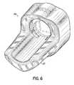
- FIG. 6is a perspective view of a face plate of an injector in accordance with the principles of the present invention.
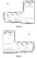
- FIG. 7is a front view of the face plate of FIG. 6 .
- FIG. 8is a rear view of the face plate of FIG. 6 .
- FIG. 9is a side view of the face plate of FIG. 6 .
- FIG. 10is a side view of the face plate of FIG. 6 taken from the opposite side from that shown in FIG. 9 .
- FIG. 11is a top view of the face plate of FIG. 6 .
- FIG. 12is a bottom view of the face plate of FIG. 6 .
- FIG. 13is a perspective view of a face plate of an injector in accordance with the principles of the present invention.
- FIG. 14is a front view of the face plate of FIG. 13 .
- FIG. 15is a rear view of the face plate of FIG. 13 .
- FIG. 16is a side view of the face plate of FIG. 13 .
- FIG. 17is a side view of the face plate of FIG. 13 taken from the opposite side from that shown in FIG. 9 .
- FIG. 18is a top view of the face plate of FIG. 13 .
- FIG. 19is a bottom view of the face plate of FIG. 13 .
- an injector 10includes a syringe mount 12 to facilitate attachment of a syringe 14 to the injector 10 in alignment with a drive ram 16 , in order to provide an injection assembly.
- the syringe 14 for use with the injector 10generally includes a body 18 (which may be in the form of an exterior cylindrical barrel), which at its forward end 20 , is integral with a conical front wall 22 .
- a neck 24terminating in a discharge tip 26 , generally extends forwardly from and may be integral with the conical front wall 22 .
- the body 18 of the syringe 14may interface with an interior wall of a pressure jacket (not shown) or a cradle 30 when such a pressure jacket or cradle 30 is present on the injector 10 .
- the syringe 14as used in conjunction with the injector 10 of the present invention, includes a syringe mating section 32 , which may be in the form of a radially outwardly extending flange 34 . This flange 34 is positioned in a plane substantially perpendicular to a longitudinal axis 36 of the syringe 14 and may generally be integral with the rearward end 38 of the body 18 of the syringe 14 .
- the flange 34is positioned into and/or in contact with the syringe mount 12 located on the forward end 40 of a housing 42 of the injector 10 .
- the syringe mating section 32 and syringe mount 12may be utilized to facilitate operative connection of the syringe 14 to the injector 10 , as will be described in greater detail below.
- the discharge tip 26 of the syringe 14has an orifice 44 defined in its remote end, which may communicate with an internal syringe cavity 46 defined within the neck 24 , the conical front wall 22 , and the body 18 of the syringe 14 .
- a rearward end 48 of the cavity 46may be defined by a generally forward facing surface 50 of a syringe plunger 52 .
- this forward facing surface 50is substantially conical.
- the surface 50may be of a slope that conforms to the slope of the interior of the conical front wall 22 .
- the syringe plunger 52may be snugly slidable within the body 18 of the syringe 14 such that the cavity 46 is of variable volume.
- Tubing(not shown) may be operatively connected to the discharge tip 26 such that fluid can be expressed from the syringe 14 through the tubing.
- the syringe plunger 52can be seen more clearly within the body 18 of the syringe 14 .
- the syringe plunger 52is preferably located proximal to and in substantial alignment with the drive ram 16 of the injector 10 .
- the drive ram 16is driven by a motor (not shown) to move in a forward or rearward motion along its longitudinal axis 54 to deploy the drive ram 16 , and thus to responsively deploy the syringe plunger 52 in a forward or rearward motion along the longitudinal axis 36 of the syringe 14 , to inject fluid into a patient or to fill the syringe 14 with fluid, respectively.
- a motornot shown
- an empty syringemay be loaded into the injector 10 while the syringe plunger 52 may be located at or near its forward-most position. Thereafter, fluid (e.g., contrast media) may be loaded into the syringe 14 by operatively connecting the syringe 14 to a source of fluid and retracting the syringe plunger 52 in a rearward direction in order to draw fluid into the syringe 14 .
- fluide.g., contrast media
- the injector 10may be designed to accommodate prefilled syringes or empty syringes of varying volumes.
- the injector 10may be adapted to receive 125 ml prefilled syringes (e.g., Ultraject® syringe commercially available from Mallinckrodt Inc. of St. Louis, Mo.). Such syringes may be used for injecting contrast media into a patient.
- These 125 ml syringesmay be prefilled with any of a range of appropriate amounts of fluid, such as 50 ml, 75 ml, 100 ml, 125 ml, or other amount.
- the injector 10may accommodate an empty syringe of any of a variety of sizes (e.g., 50 ml, 75 ml, 100 ml, 125 ml, 130 ml, etc.).
- the syringe mount 12includes a movable actuator 56 including a wall member 58 defining an orifice 60 , and at least a first movable member 62 operatively coupled to the actuator 56 and responsively movable therewith. More specifically, the syringe mount 12 of the illustrated embodiment includes first and second movable members 62 , 64 that are operatively coupled to the wall member 58 of the actuator 56 . The first and second movable members 62 , 64 include first and second pins 66 , 68 operatively connected thereto.
- the first pin 66is operatively coupled near a first end 70 of the first movable member 62
- the second pin 68is operatively coupled near a first end 72 of the second movable member 64 .
- the first and second pins 66 , 68are received in at least one slot 74 defined in the wall member 58 of the actuator 56 , to couple the first and second movable members 62 , 64 thereto.
- the actuator 56is disposed proximally of the first and second movable members 62 , 64 .
- the first and second members 62 , 64may include first and second rods 67 , 69 projecting rearwardly therefrom. These first and second rods 67 , 69 may confront and move along the outer contour of the wall member 58 of the actuator 56 , as the first and second movable members 62 , 64 move between open and closed positions.
- the slot 74is defined by the wall member 58 of the actuator 56 at a base portion 76 thereof.
- the first and second pins 66 , 68are movable (e.g., slidable and optionally rotatable) within the slot 74 .
- Each of the first and second pins 66 , 68can move from a position proximal to the center 78 of the slot 74 , to positions near first and second terminal ends 80 , 82 of the slot 74 .
- the first and second pins 66 , 68do not both move on one side of the slot 74 . Rather, the first pin 66 is adapted to move within one portion of the slot 74 , and the second pin 68 is adapted to move within another portion of the slot 74 .
- a base portion 76 of the wall member 58includes an opening 84 having a top portion thereof in a shape at least generally similar to a “V.”
- the first and second pins 66 , 68are disposed in the “V” portion of this opening 84 .
- the first and second movable members 62 , 64are in an open position (see FIG. 4A ).
- the first and second pins 66 , 68are positioned near the first and second terminal ends 80 , 82 of the “V,” the first and second movable members 62 , 64 are in a closed position (see FIG. 5A ).
- slot 74 of the illustrated embodimentis shown and described here as generally having a “V” shape, it will be recognized by those skilled in the art that such a “V” shape is not necessary, and any other shape can be used that allows the first and second movable members 62 , 64 to move sufficiently within a slot to operatively connect a syringe to an injector 10 .
- the slot 74may have a “U” or “C” shape. Further, those skilled in the art will recognize that more than one slot may be used.
- two slots forming a “V” shape proximal to the base 76 of the wall member 58can receive the first and second pins 66 , 68 near the point of the “V.”
- the slotsdo not necessarily have to be in the shape of a “V.”
- the actuator 56 and the first and second movable members 62 , 64 of the syringe mount 12are held within a face plate 86 of the housing 42 of the injector 10 (additional views of the face plate 86 may be seen in FIGS. 6-12 ).
- the face plate 86includes a proximal wall portion 88 , a distal wall portion 90 , a cradle 30 extending distally from the distal wall portion 90 , and a coupling plate 92 .
- the first and second movable members 62 , 64are located between the coupling plate 92 and the wall member 58 of the actuator 56 , and all three components are then contained within an interior cavity 94 of the face plate 86 , formed between the proximal wall portion 88 and distal wall portion 90 .
- the actuator 56 and the first and second movable members 62 , 64are movable within the interior cavity 94 .
- the coupling plate 92is preferably substantially immobile relative to the proximal and distal wall portions 88 , 90 of the face plate 86 , as it is preferably fixed to at least one of the proximal and distal wall portions 88 , 90 .
- this fixingoccurs through the use of screws 96 , which extend through orifices 97 in a rear plate 99 , orifices 98 in the proximal wall portion 88 , orifices 100 in the coupling plate 92 , and are received in orifices (not shown) in the distal wall portion 90 .
- the coupling plate 92includes first and second pivoting shafts 101 , 103 projecting from a proximal surface 105 thereof. These first and second pivoting shafts 101 , 103 are received in first and second shaft openings 107 , 109 defined in the first and second movable members 62 , 64 , respectively. As such, the first and second movable members 62 , 64 are able to exhibit a pivoting motion about the corresponding first and second pivot shafts 101 , 103 . Stated another way, the first and second movable members 62 , 64 are coupled with corresponding the first and second pivoting shafts 101 , 103 in a manner such that the movable members 62 , 64 can pivot thereabout. The first and second pivoting shafts 101 , 103 thus may be said to provide pivot points for the first and second movable members 62 , 64 .
- the flange 34 at the rearward end 38 of the syringe 14may be passed through an aperture in each of the distal wall portion 90 of the syringe mount 12 and the coupling plate 92 and may be received into the orifice 60 defined in the actuator 56 . While the rearward end 38 of the syringe 14 is located in the orifice 60 , the syringe 14 may be moved in a first direction substantially perpendicular to the longitudinal axis 54 of the drive ram 16 of the injector 10 . Herein, this direction will be referred to as a “downward” direction (as the motion is down relative to the injector 10 ).
- the motiondoes not have to be “downward,” but that the components of the syringe mount 12 can be configured such that motion in other directions can effect appropriate engagement of the syringe 14 (including, but not limited to, “upward” movement, “side-to-side” movement, or any other appropriate, substantially perpendicular movement such that the longitudinal axis 36 of the syringe 14 is moved into a substantially coaxial relationship with the longitudinal axis 54 of the drive ram 16 ).
- This downward motionresponsively moves the actuator 56 in the downward direction.
- the motion of the actuator 56 in the downward directioncauses each of the first and second pins 66 , 68 to move to the corresponding first and second ends 80 , 82 of the slot 74 defined in the base portion 76 of the wall member 58 .
- This movement of the pins 66 , 68occurs because the first and second movable members 62 , 64 cannot move in the downward direction due to the first and second pivoting shafts 101 , 103 of the fixed coupling plate 92 being located within the first and second shaft openings 107 , 109 of the first and second movable members 62 , 64 .
- the first and second pins 66 , 68move within the slot 74 to the first and second terminal ends 80 , 82 thereof.
- first and second movable members 62 , 64cannot move downwardly, they instead pivot about the pivot points provided by the first and second pivoting shafts 101 , 103 .
- the first and second movable members 62 , 64rotate about the corresponding first and second pivoting shafts 101 , 103 at the respective first and second shaft openings 107 , 109 .
- the first and second movable members 62 , 64pivot to engage (e.g., substantially, circumferentially envelop) the rearward end 38 of the syringe 14 (see FIG. 5A ).
- the first and second movable members 62 , 64engage the body 18 of the syringe 14 (rather than the flange 34 ).
- this engagement with the body 18 of the syringe 14may be characterized as a substantial enveloping of the body 18 , it may be said that this type of engagement allows for greater coverage of the syringe 14 than found in prior syringe mounts, and thus, potentially allows the syringe 14 to withstand greater injection pressures.
- first and second movable members 62 , 64are opposite one another and are positioned about the longitudinal axis 54 of the drive ram 16 . Further, the first and second movable members 62 , 64 each have an arcuate face 102 , 104 . These arcuate faces 102 , 104 are shown as being diametrically opposite one another and located exterior to the body 18 of the syringe 14 .
- the first and second movable members 62 , 64 of the syringe mount 12are in contact with the side surface of the exterior body 18 of the syringe 14 to hold the syringe 14 in place and in alignment with the drive ram 16 of the injector 10 .
- the arcuate faces 102 , 104 of the movable members 62 , 64may bear one or more types of engagement enhancing features (e.g., grooves, bumps, indentations, ridges, teeth, combinations thereof, and the like) to improve the ability of the movable members 62 , 64 to grip and/or hold the syringe 14 .
- a grip enhancing coatinge.g., Santoprene® elastomer
- first and second movable members 62 , 64alters the distance between the arcuate faces 102 , 104 as they pivot toward and away from one another.
- the first and second movable members 62 , 64are each movable.
- first and second movable members 62 , 64are not necessary for appropriate syringe engaging function.
- a single gripping membermay be used to engage the syringe 14 , thereby operatively connecting the syringe 14 to the injector 10 .
- the single movable membershould cover enough of the circumference of the syringe 14 , when in contact with the body 18 , to hold the syringe 14 against the injector 10 .
- each arm extending from a center point of the movable membermay have a degree of elasticity such that the arms may splay outwardly and inwardly to allow for insertion and/or removal of the syringe 14 .
- the wall member 58 of the actuator 56is shown as having a peripheral side surface 110 that includes a first undulating contour 106 and a second undulating contour 108 .
- the second undulating contour 108is positioned substantially opposite the first undulating contour 106 .
- Each of these first and second undulating contours 106 , 108includes a first valley 112 , a second valley 114 , and a ridge 116 disposed therebetween.
- first and second undulating contours 106 , 108are confronted by first and second projections 118 , 120 (see FIGS.
- first and second projections 118 , 120are coupled to the proximal wall portion 88 of the face plate 86 , and are spring-biased in a direction toward each of the first and second undulating contours 106 , 108 .
- the interaction of the first and second detents 118 , 120 and first and second undulating contours 106 , 108assist in maintaining the actuator 56 in either the first or second position until a user desires to move the actuator 56 to either load or unload the syringe 14 .
- the first and second pins 66 , 68may include bias springs associated with each of the first and second movable members 62 , 64 .
- one end of each of the bias springsmay be in contact with its respectively associated movable member, and the opposite end of each bias spring may seat or bear against portions of the housing 42 (or face plate 86 ) of the injector 10 .
- at least a portion of these bias springsmay be disposed about the pins 66 , 68 , which form the pivot axes of the first and second movable members 62 , 64 .
- the syringe 14is positioned relative to the wall member 58 of the actuator 56 such that the flange 34 at the rearward end 38 of the syringe 14 is received within the orifice 60 of the wall member 58 such that at least one contact point 122 on the periphery of the flange 34 contacts or can be brought into contact with a peripheral surface 124 defining the orifice 60 . More specifically, the flange 34 , in certain embodiments, may be received by a recess 125 in the actuator 56 .
- the actuator 56is shown in FIG. 4A as being in the first position, such that the first and second movable members 62 , 64 are in the open position.
- the first and second projections 118 , 120are in contact with the first valleys 112 of the corresponding first and second undulating contours 106 , 108 .
- the force of the spring bias of the first and second projections 118 , 120at least assists in preventing the wall member 58 of the actuator 56 from moving unassisted to the second position.
- the drive ram 16 of the injector 10is preferably positioned such that a plunger coupling mechanism 126 is aligned with a coupling mechanism 128 extending from a rearward face of the syringe plunger 52 (see FIG. 4B ).
- a userthen applies a force to the syringe 14 in a direction substantially perpendicular to, and towards, the longitudinal axis 54 of the drive ram 16 .
- the flange 34 of the syringe 14contacting the peripheral surface 124 of the wall member 58 , is utilized to force the wall member 58 of the actuator 56 to responsively move in a direction substantially perpendicular to the longitudinal axis 54 of the drive ram 16 .
- Enough forceis applied to overcome the spring-bias of the first and second projections 118 , 120 , such that the actuator 56 moves from the first position to the second position.
- first and second projections 118 , 120ride along the first and second undulating contours 106 , 108 from the first valleys 112 , along the ridges 116 , and into the second valleys 114 .
- the first and second projections 118 , 120may then be utilized to at least assist in maintaining the wall member 58 in the second position shown in FIG. 5A .
- the movement of the wall member 58 from the first position to the second positioncooperatively moves the slot 74 of the wall member 58 in a direction substantially perpendicular to the longitudinal axis 54 of the drive ram. And thus, the slot 74 moves relative to the first and second pins 66 , 68 , thereby causing the first and second pins 66 , 68 to move relative to and within the slot 74 . More specifically, in the illustrated embodiment, the first and second pins 66 , 68 move within the V-shaped slot from a position proximal to the point of the “V,” to positions proximal to the terminal ends of each leg of the “V” (from the position shown in FIG. 4A , to the position shown in FIG. 5A ).
- This movementcauses a responsive pivotal movement of the first and second movable members 62 , 64 from the open position to the closed position such that the rearward end 38 of the syringe 14 is engaged by the first and second movable members 62 , 64 .
- the actuator 56moves in the downward direction
- the first and second pins 66 , 68move within the slot 74 to the first and second terminal ends 80 , 82 thereof.
- the first and second movable members 62 , 64cannot move downwardly, they instead pivot about the pivot points provided by the first and second pivoting shafts 101 , 103 .
- the first and second movable members 62 , 64rotate about the first and second pivoting shafts 101 , 103 at the first and second shaft openings 107 , 109 , respectively.
- the coupling mechanism 128 at the rearward end 38 of the syringe plunger 52moves from a position not engaged with the plunger coupling mechanism 126 of the drive ram 16 to a position engaged with the plunger coupling mechanism 126 of the drive ram 16 .
- the illustrated embodimentsee FIGS.
- the syringe plunger 52 within the syringe 14is preferably positioned such that the coupling mechanism 128 on the rearward face of the syringe plunger 52 is aligned with the plunger coupling mechanism 126 of the drive ram 16 .
- the coupling mechanism 128 of the illustrated syringe plunger 52is a projection 128 extending from the rearward face of the syringe plunger 52 .
- This projection 128may be characterized as exhibiting a “T” shape having a stem portion 130 (parallel to the longitudinal axis 36 of the syringe 14 ) topped by a cap portion 132 (transverse to the longitudinal axis of the syringe 14 ).
- the cap portion 132 of the coupling mechanism 128may be received by the plunger coupling mechanism 126 , which in the illustrated embodiment, is a slot 134 formed in the forward end of the drive ram 16 .
- a slot 134is defined in the forward end of the drive ram 16 in a shape to receive the coupling mechanism 128 of the syringe 14 , and particularly the cap portion 132 thereof.
- a cross-section of the plunger coupling element 126is shown as exhibiting a J-shape (having a slot within a hook portion of the “J” configured to receive the cap portion 132 ), such that when the syringe plunger 52 is engaged with the drive ram 16 , the distal end 136 of the “J” shape is positioned distally of a part of the cap portion 132 of the coupling mechanism 128 .
- the cap portion 132 of the coupling mechanism 128is “above” the plunger coupling element 126 of the drive ram 16 .
- the cap portion 132 of the coupling mechanism 128is moved to be positioned proximally of the distal end 136 of the plunger coupling mechanism 126 of the drive ram 16 .
- an injection proceduremay be run, such as by translating the drive ram 16 forward along its longitudinal axis 54 to dispense a fluid, such as contrast media, from the syringe 14 .
- slot 134 and extension 128 of the illustrated embodimenthave shapes referred to herein as “J” and “T,” respectively, it will be recognized by those of skill in the art that any shape that facilitates coupling may be used. Additionally, while the illustrated embodiment depicts first a coupling mechanism 128 and plunger coupling mechanism 126 that result in a passive coupling, those of skill in the art will recognize that coupling mechanisms and plunger coupling mechanisms that result in an active coupling (one which involves some degree of positive gripping) may be used.
- the syringe mount 12 of the present inventionallows for the syringe 14 to be removed from the face plate 86 and/or forward end 40 of the injector 10 , when the drive ram 16 of the injector 10 is at any position. It does not require the drive ram 16 to be returned to a “home” position before detaching the syringe 14 from the injector 10 . Thus, during an injection procedure, the translation of the drive ram 16 may be stopped while the drive ram 16 is in an extended position from the front face place 86 of the injector 10 .
- a usercan then grip the syringe 14 and move it in an upward direction, thereby overcoming the spring-biased force of the first and second projections 118 , 120 to cause the actuator 56 to move from the second position to the first position.
- the first and second projections 118 , 120ride along the first and second undulating contours 106 , 108 from the second valleys 114 , over the ridges 116 , and into the first valleys 112 .
- first and second pins 66 , 68 of the first and second movable members 62 , 64will move within the V-shaped slot of the wall member 58 from a position near the terminal ends 80 , 82 of the arms of the V to a position near the point of the V.
- the actuator 56allows for enough vertical syringe movement for the T-shaped coupling mechanism on the rearward face of the syringe 14 to clear the slot on the forward end of the drive ram 16 , thereby allowing removal of the syringe 14 from the injector 10 .
Landscapes
- Health & Medical Sciences (AREA)
- Vascular Medicine (AREA)
- Engineering & Computer Science (AREA)
- Anesthesiology (AREA)
- Biomedical Technology (AREA)
- Heart & Thoracic Surgery (AREA)
- Hematology (AREA)
- Life Sciences & Earth Sciences (AREA)
- Animal Behavior & Ethology (AREA)
- General Health & Medical Sciences (AREA)
- Public Health (AREA)
- Veterinary Medicine (AREA)
- Infusion, Injection, And Reservoir Apparatuses (AREA)
Abstract
Description
Claims (38)
Priority Applications (16)
| Application Number | Priority Date | Filing Date | Title |
|---|---|---|---|
| US11/567,011US8454560B2 (en) | 2006-12-05 | 2006-12-05 | Syringe mount for a medical fluid injector |
| CA2575427ACA2575427C (en) | 2006-12-05 | 2007-01-25 | Syringe mount for a medical fluid injector |
| DE602007005755TDE602007005755D1 (en) | 2006-12-05 | 2007-01-26 | Syringe socket for a medical fluid injection device |
| AT08019894TATE507860T1 (en) | 2006-12-05 | 2007-01-26 | METHOD OF USING A SYRINGE SOCKET FOR A MEDICAL FLUID INJECTION DEVICE |
| DE602007014358TDE602007014358D1 (en) | 2006-12-05 | 2007-01-26 | A method of using a syringe barrel for a medical fluid injection device |
| AT07250314TATE463270T1 (en) | 2006-12-05 | 2007-01-26 | SYRINGE HOLDER FOR A MEDICAL FLUID INJECTION DEVICE |
| EP08019894AEP2025356B1 (en) | 2006-12-05 | 2007-01-26 | A method of using a syringe mount of medical fluid injector |
| ES07250314TES2342210T3 (en) | 2006-12-05 | 2007-01-26 | SYRINGE ASSEMBLIES FOR MEDICAL FLUID INJECTORS. |
| EP07250314AEP1930036B1 (en) | 2006-12-05 | 2007-01-26 | Syringe mount for a medical fluid injector |
| ES08019894TES2365825T3 (en) | 2006-12-05 | 2007-01-26 | A METHOD OF USE OF A SYRINGE ASSEMBLY OF A MEDICAL FLUID INJECTOR. |
| AU2007200430AAU2007200430B2 (en) | 2006-12-05 | 2007-02-01 | Syringe mount for a medical fluid injector |
| JP2007033806AJP5064829B2 (en) | 2006-12-05 | 2007-02-14 | Syringe mount for medical fluid injector |
| CN201210165887.0ACN102657907B (en) | 2006-12-05 | 2007-12-05 | Syringe mount for medical fluid injector |
| CN200710199772.2ACN101264353B (en) | 2006-12-05 | 2007-12-05 | Syringe mount for medical fluid injector |
| JP2012143267AJP2012179455A (en) | 2006-12-05 | 2012-06-26 | Syringe mount for medical fluid injector |
| US13/890,815US9248241B2 (en) | 2006-12-05 | 2013-05-09 | Syringe mount for a medical fluid injector |
Applications Claiming Priority (1)
| Application Number | Priority Date | Filing Date | Title |
|---|---|---|---|
| US11/567,011US8454560B2 (en) | 2006-12-05 | 2006-12-05 | Syringe mount for a medical fluid injector |
Related Child Applications (1)
| Application Number | Title | Priority Date | Filing Date |
|---|---|---|---|
| US13/890,815DivisionUS9248241B2 (en) | 2006-12-05 | 2013-05-09 | Syringe mount for a medical fluid injector |
Publications (2)
| Publication Number | Publication Date |
|---|---|
| US20080132839A1 US20080132839A1 (en) | 2008-06-05 |
| US8454560B2true US8454560B2 (en) | 2013-06-04 |
Family
ID=39138273
Family Applications (2)
| Application Number | Title | Priority Date | Filing Date |
|---|---|---|---|
| US11/567,011Active2030-07-14US8454560B2 (en) | 2006-12-05 | 2006-12-05 | Syringe mount for a medical fluid injector |
| US13/890,815Active2027-11-28US9248241B2 (en) | 2006-12-05 | 2013-05-09 | Syringe mount for a medical fluid injector |
Family Applications After (1)
| Application Number | Title | Priority Date | Filing Date |
|---|---|---|---|
| US13/890,815Active2027-11-28US9248241B2 (en) | 2006-12-05 | 2013-05-09 | Syringe mount for a medical fluid injector |
Country Status (9)
| Country | Link |
|---|---|
| US (2) | US8454560B2 (en) |
| EP (2) | EP2025356B1 (en) |
| JP (2) | JP5064829B2 (en) |
| CN (2) | CN102657907B (en) |
| AT (2) | ATE507860T1 (en) |
| AU (1) | AU2007200430B2 (en) |
| CA (1) | CA2575427C (en) |
| DE (2) | DE602007005755D1 (en) |
| ES (2) | ES2365825T3 (en) |
Cited By (17)
| Publication number | Priority date | Publication date | Assignee | Title |
|---|---|---|---|---|
| USD724203S1 (en)* | 2012-06-04 | 2015-03-10 | Ucb Pharma S.A. | Drive device for administering medication |
| USD726902S1 (en) | 2012-07-30 | 2015-04-14 | Ucb Pharma S.A. | Cassette device for administering medication |
| US20160151583A1 (en)* | 2009-04-23 | 2016-06-02 | Bayer Healthcare Llc | Syringe assemblies, methods of forming syringe assemblies and adapters for forming syringe assemblies |
| WO2016141087A2 (en) | 2015-03-03 | 2016-09-09 | Liebel-Flarsheim Company Llc | Single-head power injector with contrast media leakage management |
| US9669158B2 (en) | 2011-06-02 | 2017-06-06 | Ucb Biopharma Sprl | Auto-injector |
| US9757513B2 (en) | 2012-07-30 | 2017-09-12 | Ucb Biopharma Sprl | Auto-injector |
| US9757524B2 (en) | 2012-07-30 | 2017-09-12 | Ucb Biopharma Sprl | Auto-injector |
| US9757521B2 (en) | 2012-07-30 | 2017-09-12 | Ucb Biopharma Sprl | Auto-injector |
| US9764101B2 (en) | 2012-07-30 | 2017-09-19 | Ucb Biopharma Sprl | Auto-injector |
| US9789254B2 (en) | 2014-01-27 | 2017-10-17 | Ucb Biopharma Sprl | Auto-injector |
| US9821123B2 (en) | 2014-01-27 | 2017-11-21 | Ucb Biopharma Sprl | Auto-injector |
| US9901686B2 (en) | 2008-01-11 | 2018-02-27 | Ucb Biopharma Sprl | Systems and methods for administering medication |
| US10286152B2 (en) | 2012-09-28 | 2019-05-14 | Bayer Healthcare Llc | Quick release plunger |
| US10342925B2 (en) | 2014-01-27 | 2019-07-09 | Ucb Biopharma Sprl | Auto-injector |
| US10806852B2 (en) | 2014-03-19 | 2020-10-20 | Bayer Healthcare Llc | System for syringe engagement to an injector |
| US11998718B2 (en) | 2020-06-18 | 2024-06-04 | Bayer Healthcare Llc | System and method for syringe plunger engagement with an injector |
| USD1031029S1 (en) | 2003-11-25 | 2024-06-11 | Bayer Healthcare Llc | Syringe plunger |
Families Citing this family (11)
| Publication number | Priority date | Publication date | Assignee | Title |
|---|---|---|---|---|
| JP5539357B2 (en)* | 2008-08-19 | 2014-07-02 | マリンクロッド エルエルシー | Electric injector syringe clamp assembly with RFID antenna |
| JP2013501583A (en)* | 2009-08-13 | 2013-01-17 | マリンクロッド エルエルシー | Electric injector syringe assembly |
| HK1199847A1 (en)* | 2012-02-13 | 2015-07-24 | Sanofi-Aventis Deutschland Gmbh | A supplementary device for a manually operable injection device |
| US10792418B2 (en) | 2014-10-28 | 2020-10-06 | Bayer Healthcare Llc | Self-orienting pressure jacket and pressure jacket-to-injector interface |
| WO2016069714A1 (en) | 2014-10-28 | 2016-05-06 | Bayer Healthcare Llc | Self-orienting pressure jacket and pressure jacket-to-injector interface |
| US9199033B1 (en) | 2014-10-28 | 2015-12-01 | Bayer Healthcare Llc | Self-orienting syringe and syringe interface |
| NO2689315T3 (en) | 2014-10-28 | 2018-04-14 | ||
| CN111632223B (en)* | 2015-01-16 | 2022-04-08 | 贝克顿迪金森法国 | Drug storage and dispensing system for pre-filled containers |
| WO2017083622A1 (en) | 2015-11-13 | 2017-05-18 | Bayer Healthcare Llc | Nested syringe assembly |
| US11273252B2 (en)* | 2017-05-24 | 2022-03-15 | Illinois Tool Works Inc. | Injection system for injecting fluid into a patient having an injector head and a side cover |
| US11191893B2 (en) | 2018-01-31 | 2021-12-07 | Bayer Healthcare Llc | System and method for syringe engagement with injector |
Citations (91)
| Publication number | Priority date | Publication date | Assignee | Title |
|---|---|---|---|---|
| US3964139A (en) | 1975-06-16 | 1976-06-22 | Harvard Apparatus Company, Inc. | Syringe holder |
| US3983363A (en) | 1975-02-03 | 1976-09-28 | Alter R R | Electrically heated semen warming and storage unit |
| US4217993A (en) | 1977-12-02 | 1980-08-19 | Baxter Travenol Laboratories, Inc. | Flow metering apparatus for a fluid infusion system |
| US4265618A (en) | 1977-09-09 | 1981-05-05 | Solar Energy Technology, Inc. | Electrically heated endodontic syringe for injecting thermoplastic material into a root canal cavity |
| US4422942A (en) | 1981-09-09 | 1983-12-27 | Isco, Inc. | Method for liquid chromatography |
| US4460355A (en) | 1982-06-11 | 1984-07-17 | Ivac Corporation | Fluid pressure monitoring system |
| US4560979A (en) | 1983-04-22 | 1985-12-24 | Intermedicat Gmbh | Method for triggering an alarm in an infusion syringe |
| US4628499A (en) | 1984-06-01 | 1986-12-09 | Scientific-Atlanta, Inc. | Linear servoactuator with integrated transformer position sensor |
| US4634431A (en) | 1976-11-12 | 1987-01-06 | Whitney Douglass G | Syringe injector |
| US4650465A (en) | 1984-11-13 | 1987-03-17 | Liebel-Flarsheim Company | Injectors and injector consoles |
| US4743228A (en) | 1986-08-18 | 1988-05-10 | Ivac Corporation | Fluid flow monitoring method and system |
| US4755172A (en) | 1987-06-30 | 1988-07-05 | Baldwin Brian E | Syringe holder/driver and syringe arrangement and syringe/holder driver therefor |
| US4812724A (en) | 1984-11-13 | 1989-03-14 | Liebel-Flarsheim Corporation | Injector control |
| US4854324A (en) | 1984-01-31 | 1989-08-08 | Medrad, Inc. | Processor-controlled angiographic injector device |
| US4913703A (en) | 1987-09-30 | 1990-04-03 | Sherwood Medical Company | Safety interlock system for medical fluid pumps |
| US4931041A (en) | 1987-11-22 | 1990-06-05 | Fresenius Ag | Infusion syringe pump |
| US4950246A (en) | 1987-05-08 | 1990-08-21 | Spruyt-Hillen B.V. | Injection pen |
| US4994984A (en) | 1987-03-31 | 1991-02-19 | Tecnolab Snc Di Sanna Massimo & C. | System and device for supplying desired liquid volumes by means of a metering pump in variable flow rate condition |
| US5069225A (en) | 1988-09-28 | 1991-12-03 | Terumo Kabushiki Kaisha | Blood collection and/or injection device and double-ended medical needle and holder therefor |
| US5078698A (en) | 1991-02-19 | 1992-01-07 | Sterling Drug Inc. | Axial eject hypodermic syringe holder |
| US5135511A (en) | 1990-08-22 | 1992-08-04 | Becton, Dickinson And Company | Assembly for aspirating tissue, including adapter for syringe |
| US5178609A (en) | 1990-06-19 | 1993-01-12 | Kato Hatsujo Kaisha, Ltd. | Medical liquid injector for continuous transfusion |
| US5242408A (en) | 1992-09-23 | 1993-09-07 | Becton, Dickinson And Company | Method and apparatus for determining pressure and detecting occlusions in a syringe pump |
| US5261884A (en) | 1992-04-29 | 1993-11-16 | Becton, Dickinson And Company | Syringe pump control system |
| USD341760S (en) | 1992-04-21 | 1993-11-30 | Sterling Winthrop Inc. | Hand-held power injector |
| US5269762A (en) | 1992-04-21 | 1993-12-14 | Sterling Winthrop, Inc. | Portable hand-held power assister device |
| US5295966A (en) | 1992-04-29 | 1994-03-22 | Becton, Dickinson And Company | Syringe pump with biased lockable syringe clamp |
| US5300031A (en) | 1991-06-07 | 1994-04-05 | Liebel-Flarsheim Company | Apparatus for injecting fluid into animals and disposable front loadable syringe therefor |
| US5322511A (en) | 1992-04-21 | 1994-06-21 | Sterling Winthrop Inc. | Portable hand-held power injector |
| US5383858A (en) | 1992-08-17 | 1995-01-24 | Medrad, Inc. | Front-loading medical injector and syringe for use therewith |
| US5425716A (en) | 1991-08-09 | 1995-06-20 | Atom Kabushiki Kaisha | Infusion apparatus |
| USD360462S (en) | 1993-09-22 | 1995-07-18 | Sterling Winthrop Inc. | Hand-held power syringe |
| US5505704A (en) | 1993-04-02 | 1996-04-09 | Eli Lilly And Company | Manifold medication injection apparatus and method |
| US5509901A (en) | 1990-01-05 | 1996-04-23 | Milijasevic; Zoran | Controlled pressure fluid delivery device |
| US5512730A (en) | 1993-11-30 | 1996-04-30 | Spintech Inc. | Self sterilizing hypodermic syringe and method |
| US5520653A (en) | 1995-09-01 | 1996-05-28 | Medrad, Inc. | Syringe adapter for front-loading medical injector |
| USD370974S (en) | 1995-01-27 | 1996-06-18 | Hamilton Company | Manual dispensing aid for a syringe |
| US5611784A (en) | 1993-06-30 | 1997-03-18 | Hamilton Company | Manual dispensing aid for a syringe |
| US5662612A (en) | 1993-11-24 | 1997-09-02 | Liebel Flarsheim Company | Controlling plunger drives for fluid injections in animals |
| US5672155A (en) | 1996-06-14 | 1997-09-30 | Riley; Robert Q. | Fluid transfer apparatus |
| US5779675A (en) | 1995-08-25 | 1998-07-14 | Medrad, Inc. | Front load pressure jacket system with syringe holder |
| USRE35979E (en) | 1984-06-06 | 1998-12-01 | Mtfp, Inc. | Angiographic injector and angiographic syringe for use therewith |
| US5873861A (en) | 1996-11-12 | 1999-02-23 | Medrad, Inc. | Plunger systems |
| US5938637A (en) | 1997-03-14 | 1999-08-17 | Path | Single-use medicine delivery unit for needleless hypodermic injector |
| US5944694A (en) | 1996-11-12 | 1999-08-31 | Medrad, Inc. | Prefillable syringes and injectors for use therewith |
| US5947935A (en) | 1996-11-12 | 1999-09-07 | Medrad, Inc. | Syringes, syringe plungers and injector systems |
| US5947929A (en) | 1997-08-22 | 1999-09-07 | Coeur Laboratories, Inc. | Front-load angiographic injector system, angiographic syringe and plunger for angiographic syringe |
| US5964736A (en) | 1995-09-22 | 1999-10-12 | Lane; Donovan R. | Livestock biological and vaccine handling system |
| US5968015A (en) | 1997-03-05 | 1999-10-19 | Sugan Co., Ltd. | Injector head for medical use |
| US6017326A (en) | 1987-09-30 | 2000-01-25 | Sherwood Services, Ag | Safety interlock system for medical fluid pumps |
| US6042565A (en) | 1996-10-18 | 2000-03-28 | Medrad, Inc. | Syringe, injector and injector system |
| USD422356S (en) | 1997-04-07 | 2000-04-04 | Minimed Inc. | Injector for a subcutaneous infusion set |
| US6059754A (en) | 1995-02-15 | 2000-05-09 | C. R. Bard, Inc. | Pulsed lavage pump with integral power source and variable flow control |
| US6080136A (en) | 1998-06-11 | 2000-06-27 | Polyten Plastics, Llc | Angiographic syringe adapter for front-loading injector |
| US6090071A (en) | 1992-04-17 | 2000-07-18 | Science Incorporated | Fluid dispenser with fill adapter |
| US6091058A (en) | 1995-04-26 | 2000-07-18 | O.R. Solutions, Inc. | Thermal treatment system and method for maintaining integrity and ensuring sterility of surgical drapes used with surgical equipment |
| US6099502A (en) | 1995-04-20 | 2000-08-08 | Acist Medical Systems, Inc. | Dual port syringe |
| US6159183A (en) | 1996-11-22 | 2000-12-12 | Liebel Flarsheim Company | Medical fluid injector having face plate with magnetic conductors |
| US6200289B1 (en) | 1998-04-10 | 2001-03-13 | Milestone Scientific, Inc. | Pressure/force computer controlled drug delivery system and the like |
| US6221045B1 (en) | 1995-04-20 | 2001-04-24 | Acist Medical Systems, Inc. | Angiographic injector system with automatic high/low pressure switching |
| WO2001037903A2 (en) | 1999-11-24 | 2001-05-31 | Medrad, Inc. | Front-loading medical injector and syringe |
| US6245043B1 (en) | 1997-12-03 | 2001-06-12 | Alain Villette | Injector for medical use |
| US6245041B1 (en) | 1992-04-17 | 2001-06-12 | Science Incorporated | Fluid dispenser with fill adapter |
| US6259067B1 (en) | 1998-10-16 | 2001-07-10 | Medical Solutions, Inc. | Temperature control system and method for heating and maintaining medical items at desired temperatures |
| US6269340B1 (en) | 1992-10-15 | 2001-07-31 | The General Hospital | Infusion pump with an electronically loadable drug library and a user interface for loading the library |
| US6312410B1 (en) | 1995-10-30 | 2001-11-06 | Sugan Co., Ltd. | Auxiliary appliance for syringe fixation |
| US6336913B1 (en) | 1996-03-29 | 2002-01-08 | Medrad, Inc. | Front-loading syringe adapter for front-loading medical injector |
| US6368307B1 (en) | 1997-07-18 | 2002-04-09 | Liebel-Flarsheim Company | Front-loading power injector and method of loading flanged syringe therein |
| WO2002056947A1 (en) | 2001-01-18 | 2002-07-25 | Medrad, Inc. | Syringe interfaces and adapters for use with medical injectors |
| US20020107481A1 (en) | 2001-02-08 | 2002-08-08 | Reilly David M. | Syringe loading devices for use with syringes and medical injectors |
| US6454743B1 (en) | 1998-04-30 | 2002-09-24 | Schering Aktiengesellschaft | Injection device |
| US20030028145A1 (en) | 1995-04-20 | 2003-02-06 | Duchon Douglas J. | Angiographic injector system with multiple processor redundancy |
| US6582408B1 (en) | 1998-07-08 | 2003-06-24 | Thomas Buch-Rasmussen | Medical device |
| US6607508B2 (en) | 2000-04-27 | 2003-08-19 | Invivotech, Inc. | Vial injector device |
| US6610033B1 (en) | 2000-10-13 | 2003-08-26 | Incept, Llc | Dual component medicinal polymer delivery system and methods of use |
| US6652489B2 (en) | 2000-02-07 | 2003-11-25 | Medrad, Inc. | Front-loading medical injector and syringes, syringe interfaces, syringe adapters and syringe plungers for use therewith |
| US6656157B1 (en) | 1995-04-20 | 2003-12-02 | Acist Medical Systems, Inc. | Infinitely refillable syringe |
| US20030233069A1 (en) | 2002-06-14 | 2003-12-18 | John Gillespie | Infusion pump |
| US6673033B1 (en) | 1999-11-24 | 2004-01-06 | Medrad, Inc. | Injectors, injector systems and injector control |
| US6673048B1 (en) | 2000-05-24 | 2004-01-06 | Acist Medical Systems, Inc. | Pressure sleeve assembly |
| US6676635B2 (en) | 2000-02-10 | 2004-01-13 | Nemoto Kyorindo Co., Ltd. | Syringe barrel and cylinder holder |
| US6716195B2 (en) | 1999-07-30 | 2004-04-06 | Medrad, Inc. | Syringe adapters for use with an injector |
| US20040068223A1 (en) | 1999-11-24 | 2004-04-08 | Reilly David M. | Injector system including an injector drive member that automatically advances and engages a syringe plunger |
| US20040092878A1 (en) | 2001-09-19 | 2004-05-13 | Flaherty J. Christopher | Plunger for patient infusion device |
| US6808513B2 (en) | 1992-08-17 | 2004-10-26 | Medrad, Inc. | Front loading medical injector and syringe for use therewith |
| US6821013B2 (en) | 2001-12-20 | 2004-11-23 | Medrad, Inc. | Adapters, adapter systems and method for use in connection with powered injectors for agitation of multi-component fluids |
| US20040249276A1 (en)* | 2003-06-09 | 2004-12-09 | Shigeru Nemoto | Liquid injection system with cylinder adapter holding cylinder flange of liquid syringe with pair of movable holders |
| US6854620B2 (en) | 2001-04-13 | 2005-02-15 | Nipro Diabetes, Systems, Inc. | Drive system for an infusion pump |
| US6997904B2 (en) | 2002-12-24 | 2006-02-14 | Robert David Sculati | Viscous fluid injection system |
| US20060106347A1 (en) | 2004-11-17 | 2006-05-18 | Liebel-Flarsheim Company | Disposable front loadable syringe and injector |
| US7273477B2 (en)* | 2001-01-18 | 2007-09-25 | Medrad, Inc. | Syringe interfaces and syringe adapters for use with medical injectors |
Family Cites Families (4)
| Publication number | Priority date | Publication date | Assignee | Title |
|---|---|---|---|---|
| JP3831268B2 (en)* | 2002-01-30 | 2006-10-11 | 株式会社根本杏林堂 | Chemical injection device |
| US6929619B2 (en)* | 2002-08-02 | 2005-08-16 | Liebel-Flarshiem Company | Injector |
| JP4286022B2 (en)* | 2003-02-17 | 2009-06-24 | 株式会社根本杏林堂 | Chemical injection device |
| JPWO2006132146A1 (en)* | 2005-06-09 | 2009-01-08 | 株式会社根本杏林堂 | Cylinder adapter |
- 2006
- 2006-12-05USUS11/567,011patent/US8454560B2/enactiveActive
- 2007
- 2007-01-25CACA2575427Apatent/CA2575427C/enactiveActive
- 2007-01-26ESES08019894Tpatent/ES2365825T3/enactiveActive
- 2007-01-26DEDE602007005755Tpatent/DE602007005755D1/enactiveActive
- 2007-01-26ESES07250314Tpatent/ES2342210T3/enactiveActive
- 2007-01-26EPEP08019894Apatent/EP2025356B1/enactiveActive
- 2007-01-26DEDE602007014358Tpatent/DE602007014358D1/enactiveActive
- 2007-01-26ATAT08019894Tpatent/ATE507860T1/ennot_activeIP Right Cessation
- 2007-01-26EPEP07250314Apatent/EP1930036B1/enactiveActive
- 2007-01-26ATAT07250314Tpatent/ATE463270T1/ennot_activeIP Right Cessation
- 2007-02-01AUAU2007200430Apatent/AU2007200430B2/enactiveActive
- 2007-02-14JPJP2007033806Apatent/JP5064829B2/enactiveActive
- 2007-12-05CNCN201210165887.0Apatent/CN102657907B/enactiveActive
- 2007-12-05CNCN200710199772.2Apatent/CN101264353B/enactiveActive
- 2012
- 2012-06-26JPJP2012143267Apatent/JP2012179455A/enactivePending
- 2013
- 2013-05-09USUS13/890,815patent/US9248241B2/enactiveActive
Patent Citations (127)
| Publication number | Priority date | Publication date | Assignee | Title |
|---|---|---|---|---|
| US3983363A (en) | 1975-02-03 | 1976-09-28 | Alter R R | Electrically heated semen warming and storage unit |
| US3964139A (en) | 1975-06-16 | 1976-06-22 | Harvard Apparatus Company, Inc. | Syringe holder |
| US4634431A (en) | 1976-11-12 | 1987-01-06 | Whitney Douglass G | Syringe injector |
| US4265618A (en) | 1977-09-09 | 1981-05-05 | Solar Energy Technology, Inc. | Electrically heated endodontic syringe for injecting thermoplastic material into a root canal cavity |
| US4217993A (en) | 1977-12-02 | 1980-08-19 | Baxter Travenol Laboratories, Inc. | Flow metering apparatus for a fluid infusion system |
| US4422942A (en) | 1981-09-09 | 1983-12-27 | Isco, Inc. | Method for liquid chromatography |
| US4460355A (en) | 1982-06-11 | 1984-07-17 | Ivac Corporation | Fluid pressure monitoring system |
| US4560979A (en) | 1983-04-22 | 1985-12-24 | Intermedicat Gmbh | Method for triggering an alarm in an infusion syringe |
| US4854324A (en) | 1984-01-31 | 1989-08-08 | Medrad, Inc. | Processor-controlled angiographic injector device |
| US4628499A (en) | 1984-06-01 | 1986-12-09 | Scientific-Atlanta, Inc. | Linear servoactuator with integrated transformer position sensor |
| USRE35979E (en) | 1984-06-06 | 1998-12-01 | Mtfp, Inc. | Angiographic injector and angiographic syringe for use therewith |
| US4650465A (en) | 1984-11-13 | 1987-03-17 | Liebel-Flarsheim Company | Injectors and injector consoles |
| US4812724A (en) | 1984-11-13 | 1989-03-14 | Liebel-Flarsheim Corporation | Injector control |
| US4743228A (en) | 1986-08-18 | 1988-05-10 | Ivac Corporation | Fluid flow monitoring method and system |
| US4994984A (en) | 1987-03-31 | 1991-02-19 | Tecnolab Snc Di Sanna Massimo & C. | System and device for supplying desired liquid volumes by means of a metering pump in variable flow rate condition |
| US4950246A (en) | 1987-05-08 | 1990-08-21 | Spruyt-Hillen B.V. | Injection pen |
| US4755172A (en) | 1987-06-30 | 1988-07-05 | Baldwin Brian E | Syringe holder/driver and syringe arrangement and syringe/holder driver therefor |
| US4913703A (en) | 1987-09-30 | 1990-04-03 | Sherwood Medical Company | Safety interlock system for medical fluid pumps |
| US4913703B1 (en) | 1987-09-30 | 1992-06-16 | Pasqualucci Joseph | |
| US6017326A (en) | 1987-09-30 | 2000-01-25 | Sherwood Services, Ag | Safety interlock system for medical fluid pumps |
| US4931041A (en) | 1987-11-22 | 1990-06-05 | Fresenius Ag | Infusion syringe pump |
| US5069225A (en) | 1988-09-28 | 1991-12-03 | Terumo Kabushiki Kaisha | Blood collection and/or injection device and double-ended medical needle and holder therefor |
| US5509901A (en) | 1990-01-05 | 1996-04-23 | Milijasevic; Zoran | Controlled pressure fluid delivery device |
| US5178609A (en) | 1990-06-19 | 1993-01-12 | Kato Hatsujo Kaisha, Ltd. | Medical liquid injector for continuous transfusion |
| US5135511A (en) | 1990-08-22 | 1992-08-04 | Becton, Dickinson And Company | Assembly for aspirating tissue, including adapter for syringe |
| US5078698A (en) | 1991-02-19 | 1992-01-07 | Sterling Drug Inc. | Axial eject hypodermic syringe holder |
| US5300031A (en) | 1991-06-07 | 1994-04-05 | Liebel-Flarsheim Company | Apparatus for injecting fluid into animals and disposable front loadable syringe therefor |
| US5425716A (en) | 1991-08-09 | 1995-06-20 | Atom Kabushiki Kaisha | Infusion apparatus |
| US6090071A (en) | 1992-04-17 | 2000-07-18 | Science Incorporated | Fluid dispenser with fill adapter |
| US6245041B1 (en) | 1992-04-17 | 2001-06-12 | Science Incorporated | Fluid dispenser with fill adapter |
| US5269762A (en) | 1992-04-21 | 1993-12-14 | Sterling Winthrop, Inc. | Portable hand-held power assister device |
| USD341760S (en) | 1992-04-21 | 1993-11-30 | Sterling Winthrop Inc. | Hand-held power injector |
| US5322511A (en) | 1992-04-21 | 1994-06-21 | Sterling Winthrop Inc. | Portable hand-held power injector |
| US5295966A (en) | 1992-04-29 | 1994-03-22 | Becton, Dickinson And Company | Syringe pump with biased lockable syringe clamp |
| US5261884A (en) | 1992-04-29 | 1993-11-16 | Becton, Dickinson And Company | Syringe pump control system |
| US5997502A (en) | 1992-08-17 | 1999-12-07 | Medrad, Inc. | Front loading medical injector and syringe for use therewith |
| US7081105B2 (en) | 1992-08-17 | 2006-07-25 | Medrad, Inc. | Injector system having a front loading pressure jacket assembly |
| US6090064A (en) | 1992-08-17 | 2000-07-18 | Medrad, Inc. | Front loading medical injector and syringe for use therewith |
| US5383858B1 (en) | 1992-08-17 | 1996-10-29 | Medrad Inc | Front-loading medical injector and syringe for use therewith |
| US6402717B1 (en) | 1992-08-17 | 2002-06-11 | Medrad, Inc. | Front-loading medical injector and syringe for use therewith |
| US5383858A (en) | 1992-08-17 | 1995-01-24 | Medrad, Inc. | Front-loading medical injector and syringe for use therewith |
| US6808513B2 (en) | 1992-08-17 | 2004-10-26 | Medrad, Inc. | Front loading medical injector and syringe for use therewith |
| US5741232A (en) | 1992-08-17 | 1998-04-21 | Medrad, Inc. | Front loading medical injector and syringe for use therewith |
| US6733478B2 (en) | 1992-08-17 | 2004-05-11 | Medrad, Inc. | System and method for providing information from a syringe to an injector |
| US5795333A (en) | 1992-08-17 | 1998-08-18 | Medrad, Inc. | Front-loading medical injector and syringe for use therewith |
| US6475192B1 (en) | 1992-08-17 | 2002-11-05 | Medrad, Inc. | System and method for providing information from a syringe to an injector |
| US5242408A (en) | 1992-09-23 | 1993-09-07 | Becton, Dickinson And Company | Method and apparatus for determining pressure and detecting occlusions in a syringe pump |
| US6269340B1 (en) | 1992-10-15 | 2001-07-31 | The General Hospital | Infusion pump with an electronically loadable drug library and a user interface for loading the library |
| US5505704A (en) | 1993-04-02 | 1996-04-09 | Eli Lilly And Company | Manifold medication injection apparatus and method |
| US5611784A (en) | 1993-06-30 | 1997-03-18 | Hamilton Company | Manual dispensing aid for a syringe |
| USD360462S (en) | 1993-09-22 | 1995-07-18 | Sterling Winthrop Inc. | Hand-held power syringe |
| US5928197A (en) | 1993-11-24 | 1999-07-27 | Liebel-Flarsheim Company | Controlling plunger drives for fluid injections in animals |
| US5662612A (en) | 1993-11-24 | 1997-09-02 | Liebel Flarsheim Company | Controlling plunger drives for fluid injections in animals |
| US5512730A (en) | 1993-11-30 | 1996-04-30 | Spintech Inc. | Self sterilizing hypodermic syringe and method |
| USD370974S (en) | 1995-01-27 | 1996-06-18 | Hamilton Company | Manual dispensing aid for a syringe |
| US6059754A (en) | 1995-02-15 | 2000-05-09 | C. R. Bard, Inc. | Pulsed lavage pump with integral power source and variable flow control |
| US20030028145A1 (en) | 1995-04-20 | 2003-02-06 | Duchon Douglas J. | Angiographic injector system with multiple processor redundancy |
| US6344030B1 (en) | 1995-04-20 | 2002-02-05 | Acist Medical Systems, Inc. | Random speed change injector |
| US6221045B1 (en) | 1995-04-20 | 2001-04-24 | Acist Medical Systems, Inc. | Angiographic injector system with automatic high/low pressure switching |
| US6099502A (en) | 1995-04-20 | 2000-08-08 | Acist Medical Systems, Inc. | Dual port syringe |
| US6656157B1 (en) | 1995-04-20 | 2003-12-02 | Acist Medical Systems, Inc. | Infinitely refillable syringe |
| US6091058A (en) | 1995-04-26 | 2000-07-18 | O.R. Solutions, Inc. | Thermal treatment system and method for maintaining integrity and ensuring sterility of surgical drapes used with surgical equipment |
| US5779675A (en) | 1995-08-25 | 1998-07-14 | Medrad, Inc. | Front load pressure jacket system with syringe holder |
| US5938639A (en) | 1995-08-25 | 1999-08-17 | Medrad, Inc. | Front load pressure jacket system with syringe holder |
| USRE37487E1 (en) | 1995-08-25 | 2001-12-25 | Medrad, Inc. | Front load pressure jacket system with syringe holder |
| US6974443B2 (en) | 1995-08-25 | 2005-12-13 | Medrad, Inc. | Front loading injector system with pressure jacket assembly and syringe |
| US6921384B2 (en) | 1995-08-25 | 2005-07-26 | Medrad, Inc. | Front loading injector with pressure jacket assembly |
| US5899885A (en) | 1995-08-25 | 1999-05-04 | Medrad, Inc. | Front load pressure jacket system with syringe holder |
| US6241708B1 (en) | 1995-08-25 | 2001-06-05 | Medrad, Inc. | Front load pressure jacket system with syringe holder |
| US6371938B1 (en) | 1995-08-25 | 2002-04-16 | Medrad, Inc. | Front load pressure jacket system with syringe holder |
| US5520653A (en) | 1995-09-01 | 1996-05-28 | Medrad, Inc. | Syringe adapter for front-loading medical injector |
| US5964736A (en) | 1995-09-22 | 1999-10-12 | Lane; Donovan R. | Livestock biological and vaccine handling system |
| US6312410B1 (en) | 1995-10-30 | 2001-11-06 | Sugan Co., Ltd. | Auxiliary appliance for syringe fixation |
| US6676634B1 (en) | 1996-03-29 | 2004-01-13 | Medrad, Inc. | Front-loading syringe adapter for front-loading medical injector |
| US6336913B1 (en) | 1996-03-29 | 2002-01-08 | Medrad, Inc. | Front-loading syringe adapter for front-loading medical injector |
| US5672155A (en) | 1996-06-14 | 1997-09-30 | Riley; Robert Q. | Fluid transfer apparatus |
| US6042565A (en) | 1996-10-18 | 2000-03-28 | Medrad, Inc. | Syringe, injector and injector system |
| US6048334A (en) | 1996-10-18 | 2000-04-11 | Medrad, Inc. | Syringe, injector and injector system |
| US5944694A (en) | 1996-11-12 | 1999-08-31 | Medrad, Inc. | Prefillable syringes and injectors for use therewith |
| US6322535B1 (en) | 1996-11-12 | 2001-11-27 | Medrad, Inc. | Prefillable syringes and injectors for use therewith |
| US5873861A (en) | 1996-11-12 | 1999-02-23 | Medrad, Inc. | Plunger systems |
| US5947935A (en) | 1996-11-12 | 1999-09-07 | Medrad, Inc. | Syringes, syringe plungers and injector systems |
| US6159183A (en) | 1996-11-22 | 2000-12-12 | Liebel Flarsheim Company | Medical fluid injector having face plate with magnetic conductors |
| US6254572B1 (en) | 1996-11-22 | 2001-07-03 | Liebel Flarsheim Company | Medical fluid injector having watchdog circuit |
| US5968015A (en) | 1997-03-05 | 1999-10-19 | Sugan Co., Ltd. | Injector head for medical use |
| US5938637A (en) | 1997-03-14 | 1999-08-17 | Path | Single-use medicine delivery unit for needleless hypodermic injector |
| USD422356S (en) | 1997-04-07 | 2000-04-04 | Minimed Inc. | Injector for a subcutaneous infusion set |
| US6368307B1 (en) | 1997-07-18 | 2002-04-09 | Liebel-Flarsheim Company | Front-loading power injector and method of loading flanged syringe therein |
| US5947929A (en) | 1997-08-22 | 1999-09-07 | Coeur Laboratories, Inc. | Front-load angiographic injector system, angiographic syringe and plunger for angiographic syringe |
| US6245043B1 (en) | 1997-12-03 | 2001-06-12 | Alain Villette | Injector for medical use |
| US6200289B1 (en) | 1998-04-10 | 2001-03-13 | Milestone Scientific, Inc. | Pressure/force computer controlled drug delivery system and the like |
| US6454743B1 (en) | 1998-04-30 | 2002-09-24 | Schering Aktiengesellschaft | Injection device |
| US6080136A (en) | 1998-06-11 | 2000-06-27 | Polyten Plastics, Llc | Angiographic syringe adapter for front-loading injector |
| US6582408B1 (en) | 1998-07-08 | 2003-06-24 | Thomas Buch-Rasmussen | Medical device |
| US6259067B1 (en) | 1998-10-16 | 2001-07-10 | Medical Solutions, Inc. | Temperature control system and method for heating and maintaining medical items at desired temperatures |
| US6716195B2 (en) | 1999-07-30 | 2004-04-06 | Medrad, Inc. | Syringe adapters for use with an injector |
| US6743205B2 (en) | 1999-07-30 | 2004-06-01 | Medrad, Inc. | Injector systems and syringe adapters for use therewith |
| US6726657B1 (en) | 1999-07-30 | 2004-04-27 | Medrad, Inc. | Injector systems and syringe adapters for use therewith |
| US6958053B1 (en) | 1999-11-24 | 2005-10-25 | Medrad, Inc. | Injector providing drive member advancement and engagement with syringe plunger, and method of connecting a syringe to an injector |
| US20040015124A1 (en) | 1999-11-24 | 2004-01-22 | Sciulli Francis J. | Fluid delivery system having a syringe interface module separate from but in communicaiton with a control unit |
| US20040068223A1 (en) | 1999-11-24 | 2004-04-08 | Reilly David M. | Injector system including an injector drive member that automatically advances and engages a syringe plunger |
| US7029459B2 (en) | 1999-11-24 | 2006-04-18 | Medrad, Inc. | Injector system including a powered loading device for connecting a syringe to an injector |
| WO2001037903A2 (en) | 1999-11-24 | 2001-05-31 | Medrad, Inc. | Front-loading medical injector and syringe |
| US6673033B1 (en) | 1999-11-24 | 2004-01-06 | Medrad, Inc. | Injectors, injector systems and injector control |
| US20040133183A1 (en) | 2000-02-07 | 2004-07-08 | Mark Trocki | Method of preparing for a fluid injection procedure using a medical injector and a syringe |
| US6652489B2 (en) | 2000-02-07 | 2003-11-25 | Medrad, Inc. | Front-loading medical injector and syringes, syringe interfaces, syringe adapters and syringe plungers for use therewith |
| US20040116861A1 (en) | 2000-02-07 | 2004-06-17 | Mark Trocki | Front-loading injector system including a syringe and an injector having a drive piston adapted to connectively engage the syringe plunger |
| US20040133161A1 (en) | 2000-02-07 | 2004-07-08 | Mark Trocki | Front-loading syringe adapted to releasably engage a medical injector regardless of the orientation of the syringe with respect to the injector |
| US20040133153A1 (en) | 2000-02-07 | 2004-07-08 | Mark Trocki | Syringe adapter for use with a medical injector and method for adapting an injector |
| US20040133162A1 (en) | 2000-02-07 | 2004-07-08 | Mark Trocki | Front-loading medical injector adapted to releasably engage a syringe regardless of the orientation of the syringe with respect to the injector |
| US6676635B2 (en) | 2000-02-10 | 2004-01-13 | Nemoto Kyorindo Co., Ltd. | Syringe barrel and cylinder holder |
| US6607508B2 (en) | 2000-04-27 | 2003-08-19 | Invivotech, Inc. | Vial injector device |
| US7101352B2 (en) | 2000-05-24 | 2006-09-05 | Acist Medical Systems, Inc. | Pressure sleeve assembly |
| US6673048B1 (en) | 2000-05-24 | 2004-01-06 | Acist Medical Systems, Inc. | Pressure sleeve assembly |
| US6610033B1 (en) | 2000-10-13 | 2003-08-26 | Incept, Llc | Dual component medicinal polymer delivery system and methods of use |
| US7273477B2 (en)* | 2001-01-18 | 2007-09-25 | Medrad, Inc. | Syringe interfaces and syringe adapters for use with medical injectors |
| WO2002056947A1 (en) | 2001-01-18 | 2002-07-25 | Medrad, Inc. | Syringe interfaces and adapters for use with medical injectors |
| US20020107481A1 (en) | 2001-02-08 | 2002-08-08 | Reilly David M. | Syringe loading devices for use with syringes and medical injectors |
| US7025757B2 (en) | 2001-02-08 | 2006-04-11 | Medrad, Inc. | Syringe loading devices for use with syringes and medical injectors |
| US6854620B2 (en) | 2001-04-13 | 2005-02-15 | Nipro Diabetes, Systems, Inc. | Drive system for an infusion pump |
| US20040092878A1 (en) | 2001-09-19 | 2004-05-13 | Flaherty J. Christopher | Plunger for patient infusion device |
| US6821013B2 (en) | 2001-12-20 | 2004-11-23 | Medrad, Inc. | Adapters, adapter systems and method for use in connection with powered injectors for agitation of multi-component fluids |
| US20030233069A1 (en) | 2002-06-14 | 2003-12-18 | John Gillespie | Infusion pump |
| US6997904B2 (en) | 2002-12-24 | 2006-02-14 | Robert David Sculati | Viscous fluid injection system |
| EP1486219A1 (en) | 2003-06-09 | 2004-12-15 | Nemoto Kyorindo Co., Ltd. | Liquid injection system with cylinder adapter holding cylinder flange of liquid syringe with pair of movable holders |
| US20040249276A1 (en)* | 2003-06-09 | 2004-12-09 | Shigeru Nemoto | Liquid injection system with cylinder adapter holding cylinder flange of liquid syringe with pair of movable holders |
| US20060106347A1 (en) | 2004-11-17 | 2006-05-18 | Liebel-Flarsheim Company | Disposable front loadable syringe and injector |
Cited By (30)
| Publication number | Priority date | Publication date | Assignee | Title |
|---|---|---|---|---|
| USD1031029S1 (en) | 2003-11-25 | 2024-06-11 | Bayer Healthcare Llc | Syringe plunger |
| US10661023B2 (en) | 2008-01-11 | 2020-05-26 | Ucb Bioparma Sprl | Systems and methods for administering medication |
| US9901686B2 (en) | 2008-01-11 | 2018-02-27 | Ucb Biopharma Sprl | Systems and methods for administering medication |
| US20160151583A1 (en)* | 2009-04-23 | 2016-06-02 | Bayer Healthcare Llc | Syringe assemblies, methods of forming syringe assemblies and adapters for forming syringe assemblies |
| US10258740B2 (en) | 2011-06-02 | 2019-04-16 | Ucb Biopharma Sprl | Auto-injector |
| US9808575B2 (en) | 2011-06-02 | 2017-11-07 | Ucb Biopharma Sprl | Auto-injector |
| US9669158B2 (en) | 2011-06-02 | 2017-06-06 | Ucb Biopharma Sprl | Auto-injector |
| US9901674B2 (en) | 2011-06-02 | 2018-02-27 | Ucb Biopharma Sprl | Auto-injector |
| US9901673B2 (en) | 2011-06-02 | 2018-02-27 | Ucb Biopharma Sprl | Auto-injector |
| US9764084B2 (en) | 2011-06-02 | 2017-09-19 | Ucb Biopharma Sprl | Auto-injector |
| US9884152B2 (en) | 2011-06-02 | 2018-02-06 | Ucb Biopharma Sprl | Auto-injector |
| US9878092B2 (en) | 2011-06-02 | 2018-01-30 | Ucb Biopharma Sprl | Auto-injector |
| US9795734B2 (en) | 2011-06-02 | 2017-10-24 | Ucb Biopharma Sprl | Auto-injector |
| USD724203S1 (en)* | 2012-06-04 | 2015-03-10 | Ucb Pharma S.A. | Drive device for administering medication |
| US9764101B2 (en) | 2012-07-30 | 2017-09-19 | Ucb Biopharma Sprl | Auto-injector |
| US9757513B2 (en) | 2012-07-30 | 2017-09-12 | Ucb Biopharma Sprl | Auto-injector |
| USD726902S1 (en) | 2012-07-30 | 2015-04-14 | Ucb Pharma S.A. | Cassette device for administering medication |
| USD726901S1 (en)* | 2012-07-30 | 2015-04-14 | Ucb Pharma S.A. | Drive device for administering medication |
| USD755956S1 (en) | 2012-07-30 | 2016-05-10 | Ucb Pharma S.A. | Cassette device for administering medication |
| US9757521B2 (en) | 2012-07-30 | 2017-09-12 | Ucb Biopharma Sprl | Auto-injector |
| US9757524B2 (en) | 2012-07-30 | 2017-09-12 | Ucb Biopharma Sprl | Auto-injector |
| US10286152B2 (en) | 2012-09-28 | 2019-05-14 | Bayer Healthcare Llc | Quick release plunger |
| US9821123B2 (en) | 2014-01-27 | 2017-11-21 | Ucb Biopharma Sprl | Auto-injector |
| US10342925B2 (en) | 2014-01-27 | 2019-07-09 | Ucb Biopharma Sprl | Auto-injector |
| US9789254B2 (en) | 2014-01-27 | 2017-10-17 | Ucb Biopharma Sprl | Auto-injector |
| US10806852B2 (en) | 2014-03-19 | 2020-10-20 | Bayer Healthcare Llc | System for syringe engagement to an injector |
| US11103637B2 (en) | 2014-03-19 | 2021-08-31 | Bayer Healthcare Llc | System for syringe engagement to an injector |
| US11383029B2 (en) | 2014-03-19 | 2022-07-12 | Bayer Healthcare Llc | System for syringe engagement to an injector |
| WO2016141087A2 (en) | 2015-03-03 | 2016-09-09 | Liebel-Flarsheim Company Llc | Single-head power injector with contrast media leakage management |
| US11998718B2 (en) | 2020-06-18 | 2024-06-04 | Bayer Healthcare Llc | System and method for syringe plunger engagement with an injector |
Also Published As
| Publication number | Publication date |
|---|---|
| ES2365825T3 (en) | 2011-10-11 |
| CN101264353A (en) | 2008-09-17 |
| CN101264353B (en) | 2014-03-12 |
| CN102657907B (en) | 2014-10-08 |
| AU2007200430A1 (en) | 2008-06-19 |
| EP1930036A1 (en) | 2008-06-11 |
| DE602007005755D1 (en) | 2010-05-20 |
| ATE463270T1 (en) | 2010-04-15 |
| DE602007014358D1 (en) | 2011-06-16 |
| JP2008142512A (en) | 2008-06-26 |
| CN102657907A (en) | 2012-09-12 |
| JP5064829B2 (en) | 2012-10-31 |
| US9248241B2 (en) | 2016-02-02 |
| JP2012179455A (en) | 2012-09-20 |
| CA2575427A1 (en) | 2008-06-05 |
| ATE507860T1 (en) | 2011-05-15 |
| EP2025356A2 (en) | 2009-02-18 |
| AU2007200430B2 (en) | 2014-04-17 |
| ES2342210T3 (en) | 2010-07-02 |
| US20130245438A1 (en) | 2013-09-19 |
| EP2025356A3 (en) | 2009-10-21 |
| EP1930036B1 (en) | 2010-04-07 |
| EP2025356B1 (en) | 2011-05-04 |
| CA2575427C (en) | 2015-10-20 |
| US20080132839A1 (en) | 2008-06-05 |
Similar Documents
| Publication | Publication Date | Title |
|---|---|---|
| US8454560B2 (en) | Syringe mount for a medical fluid injector | |
| US8562563B2 (en) | Power injector syringe clamp assembly with RFID antenna | |
| US9814871B2 (en) | Connector assembly for syringe system | |
| US8986251B2 (en) | Method of using a syringe plunger adapter | |
| US7497843B1 (en) | Syringe interfaces, syringe adapters and injector systems | |
| JP5297372B2 (en) | Fluid injection system, method for assembling the system, and drug container used in the system | |
| WO2009023463A1 (en) | Drive ram for medical injectors | |
| TW201735957A (en) | Apparatus for needle handling | |
| US8394070B2 (en) | Device for bolus administration of contrast agent | |
| KR20230033173A (en) | Fluid injection device |
Legal Events
| Date | Code | Title | Description |
|---|---|---|---|
| AS | Assignment | Owner name:MALLINCKRODT INC., MISSOURI Free format text:ASSIGNMENT OF ASSIGNORS INTEREST;ASSIGNOR:STROBL, GEOFFREY S.;REEL/FRAME:018761/0281 Effective date:20061207 | |
| AS | Assignment | Owner name:MALLINCKRODT LLC, MISSOURI Free format text:CHANGE OF LEGAL ENTITY;ASSIGNOR:MALLINCKRODT INC.;REEL/FRAME:026754/0001 Effective date:20110623 | |
| STCF | Information on status: patent grant | Free format text:PATENTED CASE | |
| AS | Assignment | Owner name:DEUTSCHE BANK AG NEW YORK BRANCH, NEW YORK Free format text:SECURITY INTEREST;ASSIGNORS:MALLINCKRODT INTERNATIONAL FINANCE S.A.;MALLINCKRODT CB LLC;MALLINCKRODT FINANCE GMBH;AND OTHERS;REEL/FRAME:032480/0001 Effective date:20140319 | |
| AS | Assignment | Owner name:LIEBEL-FLARSHEIM COMPANY LLC, MISSOURI Free format text:ASSIGNMENT OF ASSIGNORS INTEREST;ASSIGNOR:MALLINCKRODT LLC;REEL/FRAME:034715/0531 Effective date:20140630 | |
| AS | Assignment | Owner name:LIEBEL-FLARSHEIM COMPANY LLC, OHIO Free format text:RELEASE BY SECURED PARTY;ASSIGNOR:DEUTSCHE BANK AG NEW YORK BRANCH, AS COLLATERAL AGENT;REEL/FRAME:037172/0094 Effective date:20151127 | |
| FPAY | Fee payment | Year of fee payment:4 | |
| MAFP | Maintenance fee payment | Free format text:PAYMENT OF MAINTENANCE FEE, 8TH YEAR, LARGE ENTITY (ORIGINAL EVENT CODE: M1552); ENTITY STATUS OF PATENT OWNER: LARGE ENTITY Year of fee payment:8 | |
| AS | Assignment | Owner name:INO THERAPEUTICS LLC, MISSOURI Free format text:RELEASE OF PATENT SECURITY INTERESTS RECORDED AT REEL 032480, FRAME 0001;ASSIGNOR:DEUTSCHE BANK AG NEW YORK BRANCH, AS COLLATERAL AGENT;REEL/FRAME:065609/0322 Effective date:20231114 Owner name:IKARIA THERAPEUTICS LLC, NEW JERSEY Free format text:RELEASE OF PATENT SECURITY INTERESTS RECORDED AT REEL 032480, FRAME 0001;ASSIGNOR:DEUTSCHE BANK AG NEW YORK BRANCH, AS COLLATERAL AGENT;REEL/FRAME:065609/0322 Effective date:20231114 Owner name:THERAKOS, INC., MISSOURI Free format text:RELEASE OF PATENT SECURITY INTERESTS RECORDED AT REEL 032480, FRAME 0001;ASSIGNOR:DEUTSCHE BANK AG NEW YORK BRANCH, AS COLLATERAL AGENT;REEL/FRAME:065609/0322 Effective date:20231114 Owner name:ST SHARED SERVICES LLC, MISSOURI Free format text:RELEASE OF PATENT SECURITY INTERESTS RECORDED AT REEL 032480, FRAME 0001;ASSIGNOR:DEUTSCHE BANK AG NEW YORK BRANCH, AS COLLATERAL AGENT;REEL/FRAME:065609/0322 Effective date:20231114 Owner name:INFACARE PHARMACEUTICAL CORPORATION, MISSOURI Free format text:RELEASE OF PATENT SECURITY INTERESTS RECORDED AT REEL 032480, FRAME 0001;ASSIGNOR:DEUTSCHE BANK AG NEW YORK BRANCH, AS COLLATERAL AGENT;REEL/FRAME:065609/0322 Effective date:20231114 Owner name:MALLINCKRODT PHARMA IP TRADING UNLIMITED COMPANY (F/K/A MALLINCKRODT PHARMA IP TRADING D.A.C.), IRELAND Free format text:RELEASE OF PATENT SECURITY INTERESTS RECORDED AT REEL 032480, FRAME 0001;ASSIGNOR:DEUTSCHE BANK AG NEW YORK BRANCH, AS COLLATERAL AGENT;REEL/FRAME:065609/0322 Effective date:20231114 Owner name:MALLINCKRODT PHARMACEUTICALS IRELAND LIMITED, IRELAND Free format text:RELEASE OF PATENT SECURITY INTERESTS RECORDED AT REEL 032480, FRAME 0001;ASSIGNOR:DEUTSCHE BANK AG NEW YORK BRANCH, AS COLLATERAL AGENT;REEL/FRAME:065609/0322 Effective date:20231114 Owner name:VTESSE LLC (F/K/A VTESSE INC.), MISSOURI Free format text:RELEASE OF PATENT SECURITY INTERESTS RECORDED AT REEL 032480, FRAME 0001;ASSIGNOR:DEUTSCHE BANK AG NEW YORK BRANCH, AS COLLATERAL AGENT;REEL/FRAME:065609/0322 Effective date:20231114 Owner name:SUCAMPO PHARMA AMERICAS LLC, MISSOURI Free format text:RELEASE OF PATENT SECURITY INTERESTS RECORDED AT REEL 032480, FRAME 0001;ASSIGNOR:DEUTSCHE BANK AG NEW YORK BRANCH, AS COLLATERAL AGENT;REEL/FRAME:065609/0322 Effective date:20231114 Owner name:STRATATECH CORPORATION, WISCONSIN Free format text:RELEASE OF PATENT SECURITY INTERESTS RECORDED AT REEL 032480, FRAME 0001;ASSIGNOR:DEUTSCHE BANK AG NEW YORK BRANCH, AS COLLATERAL AGENT;REEL/FRAME:065609/0322 Effective date:20231114 Owner name:SPECGX LLC, MISSOURI Free format text:RELEASE OF PATENT SECURITY INTERESTS RECORDED AT REEL 032480, FRAME 0001;ASSIGNOR:DEUTSCHE BANK AG NEW YORK BRANCH, AS COLLATERAL AGENT;REEL/FRAME:065609/0322 Effective date:20231114 Owner name:OCERA THERAPEUTICS LLC (F/K/A OCERA THERAPEUTICS, INC.), MISSOURI Free format text:RELEASE OF PATENT SECURITY INTERESTS RECORDED AT REEL 032480, FRAME 0001;ASSIGNOR:DEUTSCHE BANK AG NEW YORK BRANCH, AS COLLATERAL AGENT;REEL/FRAME:065609/0322 Effective date:20231114 Owner name:MALLINCKRODT ARD IP UNLIMITED COMPANY (F/K/A MALLINCKRODT ARD IP LIMITED), IRELAND Free format text:RELEASE OF PATENT SECURITY INTERESTS RECORDED AT REEL 032480, FRAME 0001;ASSIGNOR:DEUTSCHE BANK AG NEW YORK BRANCH, AS COLLATERAL AGENT;REEL/FRAME:065609/0322 Effective date:20231114 Owner name:MALLINCKRODT HOSPITAL PRODUCTS IP UNLIMITED COMPANY (F/K/A MALLINCKRODT HOSPITAL PRODUCTS IP LIMITED), IRELAND Free format text:RELEASE OF PATENT SECURITY INTERESTS RECORDED AT REEL 032480, FRAME 0001;ASSIGNOR:DEUTSCHE BANK AG NEW YORK BRANCH, AS COLLATERAL AGENT;REEL/FRAME:065609/0322 Effective date:20231114 Owner name:MEH, INC., MISSOURI Free format text:RELEASE OF PATENT SECURITY INTERESTS RECORDED AT REEL 032480, FRAME 0001;ASSIGNOR:DEUTSCHE BANK AG NEW YORK BRANCH, AS COLLATERAL AGENT;REEL/FRAME:065609/0322 Effective date:20231114 Owner name:IMC EXPLORATION COMPANY, MISSOURI Free format text:RELEASE OF PATENT SECURITY INTERESTS RECORDED AT REEL 032480, FRAME 0001;ASSIGNOR:DEUTSCHE BANK AG NEW YORK BRANCH, AS COLLATERAL AGENT;REEL/FRAME:065609/0322 Effective date:20231114 Owner name:MALLINCKRODT US HOLDINGS LLC, MISSOURI Free format text:RELEASE OF PATENT SECURITY INTERESTS RECORDED AT REEL 032480, FRAME 0001;ASSIGNOR:DEUTSCHE BANK AG NEW YORK BRANCH, AS COLLATERAL AGENT;REEL/FRAME:065609/0322 Effective date:20231114 Owner name:MALLINCKRODT VETERINARY, INC., MISSOURI Free format text:RELEASE OF PATENT SECURITY INTERESTS RECORDED AT REEL 032480, FRAME 0001;ASSIGNOR:DEUTSCHE BANK AG NEW YORK BRANCH, AS COLLATERAL AGENT;REEL/FRAME:065609/0322 Effective date:20231114 Owner name:MALLINCKRODT BRAND PHARMACEUTICALS LLC (F/K/A MALLINCKRODT BRAND PHARMACEUTICALS, INC.), MISSOURI Free format text:RELEASE OF PATENT SECURITY INTERESTS RECORDED AT REEL 032480, FRAME 0001;ASSIGNOR:DEUTSCHE BANK AG NEW YORK BRANCH, AS COLLATERAL AGENT;REEL/FRAME:065609/0322 Effective date:20231114 Owner name:LIEBEL-FLARSHEIM COMPANY LLC, MISSOURI Free format text:RELEASE OF PATENT SECURITY INTERESTS RECORDED AT REEL 032480, FRAME 0001;ASSIGNOR:DEUTSCHE BANK AG NEW YORK BRANCH, AS COLLATERAL AGENT;REEL/FRAME:065609/0322 Effective date:20231114 Owner name:LAFAYETTE PHARMACEUTICALS LLC, MISSOURI Free format text:RELEASE OF PATENT SECURITY INTERESTS RECORDED AT REEL 032480, FRAME 0001;ASSIGNOR:DEUTSCHE BANK AG NEW YORK BRANCH, AS COLLATERAL AGENT;REEL/FRAME:065609/0322 Effective date:20231114 Owner name:MALLINCKRODT LLC, MISSOURI Free format text:RELEASE OF PATENT SECURITY INTERESTS RECORDED AT REEL 032480, FRAME 0001;ASSIGNOR:DEUTSCHE BANK AG NEW YORK BRANCH, AS COLLATERAL AGENT;REEL/FRAME:065609/0322 Effective date:20231114 Owner name:MALLINCKRODT ENTERPRISES LLC, MISSOURI Free format text:RELEASE OF PATENT SECURITY INTERESTS RECORDED AT REEL 032480, FRAME 0001;ASSIGNOR:DEUTSCHE BANK AG NEW YORK BRANCH, AS COLLATERAL AGENT;REEL/FRAME:065609/0322 Effective date:20231114 Owner name:MALLINCKRODT ENTERPRISES HOLDINGS LLC (F/K/A MALLINCKRODT ENTERPRISES HOLDINGS, INC.), MISSOURI Free format text:RELEASE OF PATENT SECURITY INTERESTS RECORDED AT REEL 032480, FRAME 0001;ASSIGNOR:DEUTSCHE BANK AG NEW YORK BRANCH, AS COLLATERAL AGENT;REEL/FRAME:065609/0322 Effective date:20231114 Owner name:CNS THERAPEUTICS, INC., MISSOURI Free format text:RELEASE OF PATENT SECURITY INTERESTS RECORDED AT REEL 032480, FRAME 0001;ASSIGNOR:DEUTSCHE BANK AG NEW YORK BRANCH, AS COLLATERAL AGENT;REEL/FRAME:065609/0322 Effective date:20231114 Owner name:LUDLOW LLC (F/K/A LUDLOW CORPORATION), MISSOURI Free format text:RELEASE OF PATENT SECURITY INTERESTS RECORDED AT REEL 032480, FRAME 0001;ASSIGNOR:DEUTSCHE BANK AG NEW YORK BRANCH, AS COLLATERAL AGENT;REEL/FRAME:065609/0322 Effective date:20231114 Owner name:MNK 2011 LLC (F/K/A MALLINCKRODT INC.), MISSOURI Free format text:RELEASE OF PATENT SECURITY INTERESTS RECORDED AT REEL 032480, FRAME 0001;ASSIGNOR:DEUTSCHE BANK AG NEW YORK BRANCH, AS COLLATERAL AGENT;REEL/FRAME:065609/0322 Effective date:20231114 Owner name:MALLINCKRODT US POOL LLC, MISSOURI Free format text:RELEASE OF PATENT SECURITY INTERESTS RECORDED AT REEL 032480, FRAME 0001;ASSIGNOR:DEUTSCHE BANK AG NEW YORK BRANCH, AS COLLATERAL AGENT;REEL/FRAME:065609/0322 Effective date:20231114 Owner name:MALLINCKRODT CARRIBEAN, INC., MISSOURI Free format text:RELEASE OF PATENT SECURITY INTERESTS RECORDED AT REEL 032480, FRAME 0001;ASSIGNOR:DEUTSCHE BANK AG NEW YORK BRANCH, AS COLLATERAL AGENT;REEL/FRAME:065609/0322 Effective date:20231114 Owner name:MALLINCKRODT US HOLDINGS LLC (F/K/A MALLINCKRODT US HOLDINGS INC.), MISSOURI Free format text:RELEASE OF PATENT SECURITY INTERESTS RECORDED AT REEL 032480, FRAME 0001;ASSIGNOR:DEUTSCHE BANK AG NEW YORK BRANCH, AS COLLATERAL AGENT;REEL/FRAME:065609/0322 Effective date:20231114 Owner name:MALLINCKRODT FINANCE GMBH, SWITZERLAND Free format text:RELEASE OF PATENT SECURITY INTERESTS RECORDED AT REEL 032480, FRAME 0001;ASSIGNOR:DEUTSCHE BANK AG NEW YORK BRANCH, AS COLLATERAL AGENT;REEL/FRAME:065609/0322 Effective date:20231114 Owner name:MALLINCKRODT CB LLC, MISSOURI Free format text:RELEASE OF PATENT SECURITY INTERESTS RECORDED AT REEL 032480, FRAME 0001;ASSIGNOR:DEUTSCHE BANK AG NEW YORK BRANCH, AS COLLATERAL AGENT;REEL/FRAME:065609/0322 Effective date:20231114 Owner name:MALLINCKRODT INTERNATIONAL FINANCE S.A., LUXEMBOURG Free format text:RELEASE OF PATENT SECURITY INTERESTS RECORDED AT REEL 032480, FRAME 0001;ASSIGNOR:DEUTSCHE BANK AG NEW YORK BRANCH, AS COLLATERAL AGENT;REEL/FRAME:065609/0322 Effective date:20231114 | |
| MAFP | Maintenance fee payment | Free format text:PAYMENT OF MAINTENANCE FEE, 12TH YEAR, LARGE ENTITY (ORIGINAL EVENT CODE: M1553); ENTITY STATUS OF PATENT OWNER: LARGE ENTITY Year of fee payment:12 |