US8454524B2 - Wireless flow sensor - Google Patents
Wireless flow sensorDownload PDFInfo
- Publication number
- US8454524B2 US8454524B2US11/931,127US93112707AUS8454524B2US 8454524 B2US8454524 B2US 8454524B2US 93112707 AUS93112707 AUS 93112707AUS 8454524 B2US8454524 B2US 8454524B2
- Authority
- US
- United States
- Prior art keywords
- radio frequency
- masking element
- frequency tag
- tag
- sensor
- Prior art date
- Legal status (The legal status is an assumption and is not a legal conclusion. Google has not performed a legal analysis and makes no representation as to the accuracy of the status listed.)
- Active, expires
Links
Images


Classifications
- A—HUMAN NECESSITIES
- A61—MEDICAL OR VETERINARY SCIENCE; HYGIENE
- A61B—DIAGNOSIS; SURGERY; IDENTIFICATION
- A61B5/00—Measuring for diagnostic purposes; Identification of persons
- A61B5/0002—Remote monitoring of patients using telemetry, e.g. transmission of vital signals via a communication network
- A61B5/0015—Remote monitoring of patients using telemetry, e.g. transmission of vital signals via a communication network characterised by features of the telemetry system
- A—HUMAN NECESSITIES
- A61—MEDICAL OR VETERINARY SCIENCE; HYGIENE
- A61B—DIAGNOSIS; SURGERY; IDENTIFICATION
- A61B5/00—Measuring for diagnostic purposes; Identification of persons
- A61B5/0002—Remote monitoring of patients using telemetry, e.g. transmission of vital signals via a communication network
- A61B5/0031—Implanted circuitry
- A—HUMAN NECESSITIES
- A61—MEDICAL OR VETERINARY SCIENCE; HYGIENE
- A61B—DIAGNOSIS; SURGERY; IDENTIFICATION
- A61B5/00—Measuring for diagnostic purposes; Identification of persons
- A61B5/0059—Measuring for diagnostic purposes; Identification of persons using light, e.g. diagnosis by transillumination, diascopy, fluorescence
- A61B5/0075—Measuring for diagnostic purposes; Identification of persons using light, e.g. diagnosis by transillumination, diascopy, fluorescence by spectroscopy, i.e. measuring spectra, e.g. Raman spectroscopy, infrared absorption spectroscopy
- A—HUMAN NECESSITIES
- A61—MEDICAL OR VETERINARY SCIENCE; HYGIENE
- A61B—DIAGNOSIS; SURGERY; IDENTIFICATION
- A61B5/00—Measuring for diagnostic purposes; Identification of persons
- A61B5/07—Endoradiosondes
- A61B5/076—Permanent implantation
- A—HUMAN NECESSITIES
- A61—MEDICAL OR VETERINARY SCIENCE; HYGIENE
- A61M—DEVICES FOR INTRODUCING MEDIA INTO, OR ONTO, THE BODY; DEVICES FOR TRANSDUCING BODY MEDIA OR FOR TAKING MEDIA FROM THE BODY; DEVICES FOR PRODUCING OR ENDING SLEEP OR STUPOR
- A61M27/00—Drainage appliance for wounds or the like, i.e. wound drains, implanted drains
- A61M27/002—Implant devices for drainage of body fluids from one part of the body to another
- A61M27/006—Cerebrospinal drainage; Accessories therefor, e.g. valves
- A—HUMAN NECESSITIES
- A61—MEDICAL OR VETERINARY SCIENCE; HYGIENE
- A61M—DEVICES FOR INTRODUCING MEDIA INTO, OR ONTO, THE BODY; DEVICES FOR TRANSDUCING BODY MEDIA OR FOR TAKING MEDIA FROM THE BODY; DEVICES FOR PRODUCING OR ENDING SLEEP OR STUPOR
- A61M2205/00—General characteristics of the apparatus
- A61M2205/33—Controlling, regulating or measuring
- A61M2205/3331—Pressure; Flow
- A—HUMAN NECESSITIES
- A61—MEDICAL OR VETERINARY SCIENCE; HYGIENE
- A61M—DEVICES FOR INTRODUCING MEDIA INTO, OR ONTO, THE BODY; DEVICES FOR TRANSDUCING BODY MEDIA OR FOR TAKING MEDIA FROM THE BODY; DEVICES FOR PRODUCING OR ENDING SLEEP OR STUPOR
- A61M2205/00—General characteristics of the apparatus
- A61M2205/35—Communication
- A61M2205/3507—Communication with implanted devices, e.g. external control
- A61M2205/3523—Communication with implanted devices, e.g. external control using telemetric means
Definitions
- the present applicationgenerally relates to devices and methods for non-invasively monitoring and/or measuring the flow of a fluid, and more particularly for monitoring and/or measuring the flow of a fluid in an implantable medical device.
- treatment of hydrocephaluscan involve monitoring the flow rate of cerebrospinal fluid through a hydrocephalus shunt.
- Hydrocephalusis a neurological condition that is caused by the abnormal accumulation of cerebrospinal fluid (CSF) within the ventricles, or cavities, of the brain.
- CSFcerebrospinal fluid
- CSFis a clear, colorless fluid that is primarily produced by the choroid plexus and surrounds the brain and spinal cord, aiding in their protection.
- Hydrocephaluscan arise when the normal drainage of CSF in the brain is blocked in some way, which creates an imbalance between the amount of CSF produced by the choroid plexus and the rate at which CSF is absorbed into the bloodstream, thereby increasing pressure on the brain.
- Hydrocephalusis most often treated by surgically implanting a shunt system in a patient.
- the shunt systemdiverts the flow of CSF from the ventricle to another area of the body where the CSF can be absorbed as part of the circulatory system.
- Shunt systemscome in a variety of models and typically share similar functional components. These components include a ventricular catheter, which is introduced through a burr hole in the skull and implanted in the patient's ventricle, a drainage catheter that carries the CSF to its ultimate drainage site, and optionally a flow-control mechanism, e.g., shunt valve, that regulates the one-way flow of CSF from the ventricle to the drainage site to maintain normal pressure within the ventricles. It is this flow of CSF which may need to be measured.
- a flow-control mechanisme.g., shunt valve
- measuring the flow of CSFcan be accomplished by a flow sensor using temperature differentials between two points, e.g., with a mechanism for heating or cooling the CSF in a particular section of the catheter.
- a flow sensorcapable of more accurate and/or direct measurements of flow, without the need for heating or cooling equipment, and to provide a straightforward way to retrieve the measurements from the sensor.
- Such considerationscan apply to a wide range of applications involving the measurement of gas and fluid flow, including CSF, within an implanted device or an embedded, encapsulated, or relatively inaccessible space.
- an exemplary implantable sensor for measuring fluid flowcan have a sensor housing adapted to receive fluid flow therethrough.
- the sensor housingcan have a domed portion defining a reservoir therein, and the implantable sensor can measure the flow rate of fluid through the reservoir.
- a radio frequency tagcan be located within the sensor housing. The radio frequency tag can be adapted to interact with a wireless signal and to produce a response to the wireless signal.
- the implantable sensorcan also include a masking element that is disposed in the sensor housing.
- the masking element and the radio frequency tagcan be configured to move relative to one another, for example the masking element moving, the radio frequency tag moving, or both, to alter the response of the radio frequency tag and thereby indicate a rate of fluid flowing through the sensor housing.
- the masking elementfor example, can include a conductive member that alters the response of the radio frequency tag by covering at least a portion of it.
- the response of the radio frequency tagcan have at least one characteristic, such as a resonant frequency, harmonic spectra, decay characteristic, and Q factor, that corresponds to the flow rate.
- the implantable sensorcan also have a valve assembly that is in fluid communication with the sensor housing and that is adapted to control a rate of fluid flowing through the sensor housing.
- the radio frequency tagcan include a disk having an asymmetrical antenna, and the masking element can be configured to mask at least part of the antenna.
- the radio frequency tagcan also include a chip for storing data and an antenna adapted to communicate the stored data to an external reading device.
- the masking elementcan be configured to rotate in response to the flow rate of fluid through the sensor housing.
- the masking elementcan include a disk formed at least in part of a conductive material and configured to rotate around an axis thereof.
- the masking elementcan be configured to rotate around an axis thereof to mask different parts of the radio frequency tag such that the response of the radio frequency tag to the wireless signal is periodic.
- the rotationcan selectively mask part of the radio frequency tag such that the response of the radio frequency tag to the wireless signal is periodic.
- the conductive materialcan be in the form of, for example, a spiral or a plurality of discrete conductive sections.
- the masking elementcan include a disk having a pattern of conductive material formed thereon and a biasing element, such as a spring, calibrated to resist rotation of the disk caused by the flow rate of fluid through the sensor housing.
- the masking elementcan have a wedge formed at least in part of a conductive material and the masking element can be configured to translate in relation to the flow rate of fluid through the sensor housing.
- an implantable sensorwhich has a sensor housing adapted to receive fluid flow therethrough, and a conductive member disposed within the valve assembly.
- the conductive membercan be configured to selectively cover at least a portion of a radio frequency tag and thereby alter a response thereof to a wireless signal to indicate a rate of fluid flowing through the sensor housing.
- the response of the radio frequency tagcan have at least one measurable characteristic, such as resonant frequency, harmonic spectra, decay characteristic, and Q factor, that can indicate the flow rate.
- the frequency tagcan be configured to move relative to the conductive member, which can result in the frequency tag being selectively covered.
- the radio frequency tagcan also include a disk having an asymmetrical antenna formed thereon.
- the conductive membercan be configured to move relative to the radio frequency tag, which can result in the frequency tag being selectively covered.
- the conductive membercan form part of a rotatable disk, for example.
- the implantable sensorcan include a valve assembly that is in fluid communication with the sensor housing and that is adapted to control the rate of fluid flowing through the sensor housing.
- an exemplary method for measuring fluid flowcan include positioning a sensor housing between an inlet tube and an outlet tube, the sensor housing having a radio frequency tag disposed therein.
- the methodcan further include transmitting a wireless signal to the radio frequency tag from a reading device, and wirelessly receiving a response from the radio frequency tag that indicates a rate of fluid flowing through the sensor housing.
- the responsecan change in relation to the rate of fluid flowing through the sensor housing, and/or it can include a periodic signal.
- the methodcan also include analyzing the response to detect any of resonant frequency, harmonic spectra, decay characteristic, and Q factor of an antenna included in the radio frequency tag, and/or receiving a response from the radio frequency tag that communicates data previously stored therein.
- the methodcan further include coupling the inlet tube to a catheter within a patient's ventricle, and coupling the outlet tube to a drainage catheter for draining the patient's cerebrospinal fluid.
- the methodcan also include coupling the sensor housing to a valve assembly adapted to control a rate of fluid flowing through the sensor housing.
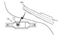
- FIG. 1Ais a top view of one exemplary implantable valve suitable for use in a hydrocephalus shunt and including a flow sensor.
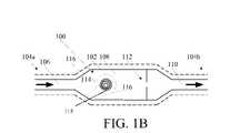
- FIG. 1Bis a schematic view of one exemplary embodiment of an implantable sensor having a housing with a radio frequency tag and a masking element disposed therein for measuring the flow of a fluid therethrough;
- FIG. 2Ais a top view of one exemplary embodiment of a radio frequency tag and a masking element for use with the implantable sensor shown in FIG. 1B ;
- FIG. 2Bis a top view of the radio frequency tag and masking element shown in FIG. 2A following rotation of the masking element;
- FIG. 3is a schematic view of an exemplary configuration for coupling the flow of a fluid to a radio frequency tag and/or masking element to cause rotation thereof;
- FIG. 4is a graph illustrating amplitude vs. frequency characteristics of an exemplary response from a radio frequency tag in an implantable sensor
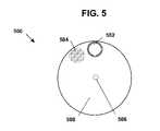
- FIG. 5is a top view of another embodiment of a radio frequency tag and a masking element
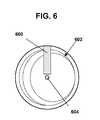
- FIG. 6is a top view of another embodiment of a radio frequency tag and a masking element
- FIG. 7Ais a top view of another embodiment of a radio frequency tag and a masking element
- FIG. 7Bis a top view the radio frequency tag and masking element shown in FIG. 7A following translation of the masking element and/or radio frequency tag;
- FIG. 8is a schematic view of an exemplary configuration for coupling the flow of a fluid to a radio frequency tag and/or masking element to cause translation thereof;
- FIG. 9Ais a schematic diagram of one exemplary model of a circuit having resonance characteristics
- FIG. 9Bis a graph of an output voltage signal as a function of frequency for the circuit shown in FIG. 9A ;
- FIG. 9Cis a graph of an output voltage signal as a function of frequency for the circuit shown in FIG. 9A ;
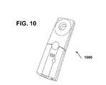
- FIG. 10is a perspective view of an exemplary reading device for reading a flow rate from an implantable sensor.
- FIG. 11illustrates the implantable sensor shown in FIG. 1 implanted in a body and being read by the reading device shown in FIG. 10 .
- the present applicationgenerally provides methods and devices for non-invasively measuring or quantifying the flow of a fluid through as device and for indicating that information to another device, e.g., telemetrically.
- the methods and devicesare particularly useful in the context of implantable devices, such as hydrocephalus shunts and associated valves. While the description herein sometimes refers to hydrocephalus shunts, one skilled in the art will understand that the devices and methods described herein can be used in a wide variety of methods and devices in which it is desirable to measure fluid flow.
- FIG. 1Aillustrates one exemplary embodiment of an implantable sensor in the context of an implantable valve for a hydrocephalus shunt.
- the implantable valve 101can include a housing 102 with proximal and distal ends 104 a , 104 b for receiving fluid flow (such as CSF) therethrough between an inlet port 106 and an outlet port 110 .
- the housing 102can have virtually any configuration, shape, and size. In many embodiments, the size and shape of the housing 102 can be adapted for implantation in a body, e.g., subcutaneous implantation. In the embodiment shown in FIG.
- the housing 102has a substantially linear configuration with a reservoir 108 having a larger area than the ports 106 , 110 which can be advantageous for checking the shunt's patency, tapping the CSF, or to administer therapy.
- the reservoir 108can also house a flow sensor, as will be described in more detailed below, and can also house a pressure sensor for measuring the pressure of fluid in the reservoir.
- suitable pressure sensorsare described in co-pending, commonly assigned U.S. patent application Ser. No. 10/907,665, entitled “Pressure Sensing Valve” by Mauge et al., filed Apr. 11, 2005 (now published as U.S. Publication No. 2006-0211946 A1), filed herewith, and in U.S. Pat. No.
- the implantable valve 101can also include a valve assembly 112 for controlling the flow of fluid through the valve 101 according to remotely or telemetrically selectable settings.
- a coatingcan be disposed over the valve 101 . Further information on implantable valves can be obtained from U.S. Publication No. 2006-0211946 A1, referenced above.
- FIG. 1Bschematically illustrates one exemplary embodiment of an implantable sensor in the housing 102 .
- Fluide.g., CSF
- Fluidcan flow as indicated by directional arrows through the housing 102 from an inlet (fluid entry) port 106 at the proximal end 104 a , through a reservoir 108 , and out an outlet (fluid exit) port 110 at the distal end 104 b .
- the reservoir 108is not necessary (for example, the housing can be in the form of a catheter or tube), but can be advantageous for accommodating other components of the sensor or device therein.
- the sensor 100can also have a radio frequency (RF) tag 114 disposed in the reservoir 108 , a masking element 115 associated with the RF tag 114 (for clarity, the RF tag 114 and the masking element 115 are represented together in FIG. 1B , although they need not be one component, or be similarly sized and oriented).
- RF tag and masking elementare shown disposed within the reservoir 108 , they can be positioned at any location within a fluid system as long as they can be used to indicate a flow rate of fluid in the system.
- the RF tag 114 and the masking element 115can be configured to move relative to one another in response to and/or in relation to the rate of flow of fluid through the housing, and to indicate the rate of fluid flow to an external reading device.
- the RF tag 114can further store data, such as identification information (for example, for the sensor and/or for the patient) and flow rate history, which can be communicated to the external reading device.
- the housing 102can also contain a valve assembly for controlling the flow of fluid from the inlet port 106 to the outlet port 110 , the sensor 100 measuring the controlled flow of fluid therethrough.
- the proximal and distal ends 104 a , 104 b of the sensor 100can each be open and adapted to couple to another medical device, such as a catheter.
- FIG. 2Ashows one exemplary embodiment of a masking element 115 associated with an RF tag 114 in which the masking element 115 is in the form of a disk with a conductive portion 202 and a non-conductive (or differently conductive) portion 208 .
- the conductive portion 202can be a material, such as silver, gold, copper, aluminum, or others known in the art, etc., deposited on the disk.
- the conductive portion 202can also be attached or coupled to the disk, or it can be a non-circular portion that fits together with a non-conductive portion 208 to form the complete disk, and so on.
- the conductive portion 202can have a variety of shapes, but as shown it is in the shape of a spiral. Alternatively, the conductive portion can be in the shape of a strip of varying width, can have one or more discrete portions of varying size (e.g., a plurality of discrete rectangular shapes), and can have virtually any size and shape that is rotationally asymmetric. As shown in FIG. 2A , the RF tag 114 can be disposed behind the masking element, and particularly behind the spiral portion formed of conductive material 202 . (In other embodiments, the RF tag can be disposed behind or in front of the masking element.) In use, the flow of a fluid through a housing 102 , such as is shown in FIG.
- FIG. 2Billustrates one possible result of such relative movement.
- a narrow portion of the conductive material 202covers the RF tag 114 .
- the response of the RF tag 114 to an external signal (e.g., from a reading device emitting a signal at one or more radio frequencies) in FIG. 2Acan differ from that of FIG. 2B and can indicate such relative position and/or movement.
- a characteristic of the response of the RF tag 114can change depending on the relative position or motion of the masking element 115 and the RF tag 114 , to indicate the flow rate of fluid within the sensor housing.
- the masking element 115can rotate around its central axis 206 at a speed relative to the RF tag 114 to indicate a fluid flow rate.
- an element 300can be coupled to fluid flowing in direction 302 in a housing 102 via surface features 304 formed on the element 300 , causing the element 300 to rotate as shown by arrow 306 .
- the element 300can be a masking element 115 itself or alternatively it can be coupled to the masking element 115 , for example, via a shaft, gears, and so on.
- the resulting relative motion of the masking element 115 and the RF tag 114can be manifested as a periodic radio frequency signal, such as is shown in FIG. 4 .
- the period of the signal(for example, the periodicity of the f max peaks in FIG. 4 , or other metric) can be correlated to the flow rate of the fluid.
- the nature of the rotation of the masking element 115 relative to the RF tag 114can vary and can be used to sense or measure other characteristics.
- the masking element 115in response to a pressure from flowing fluid the masking element 115 can rotate to a position relative to the RF tag 114 and stop.
- a spring 308can be disposed on the rotational axis of element 300 to resist the rotation thereof, and the spring 308 can be calibrated such that a given force or pressure causes a known degree of rotation, or rotational deflection, in the element 300 .
- the resulting relative position of the masking element 115 and the RF tagcan indicate the pressure via the response of the RF tag to a radio frequency signal, as described above.
- FIG. 5shows an exemplary masking element 500 in the form of a disk which includes a conductive portion 504 disposed within a disk of non-conductive, or differently conductive, material 508 .
- the conductive portion 504is in the form of a circle sized to cover the RF tag 502 completely, although in other embodiments, the conductive portion can be adapted to cover the RF tag 502 partially.
- the masking element 500can be coupled to flowing fluid so as to rotate around a central axis 506 in relation to the rate of flow, as previously described. Rotation of the masking element 500 can result in a periodic sudden change or discontinuity in the RF tag's response and thereby indicate the flow rate.
- a masking element 600can be in the form of a rectangle, square, or virtually any other shape, and it can be associated with an RF tag 602 having an asymmetric shape.
- the RF tag 602can be in the form of a disk with a rotationally asymmetric antenna pattern formed thereon. The pattern can include, for example, antenna lines with varying width, spacing, orientation, and so on.
- the masking element 600can be fixed within the housing, and the disk forming the RF tag 602 can be coupled to flowing fluid, e.g., in the housing as shown in FIG. 1B , so as to rotate around axis 604 in relation to the flow rate, as previously described.
- Such rotationcan cause a change or variations in the response of the RF tag 602 as the conductive masking element 600 covers different portions of the asymmetric antenna of the RF tag 602 .
- the responsecan have characteristics, such as resonance frequency, harmonic spectra, decay characteristics, and/or Q factor, which can change as a result of such rotation and which can be detected in the response of the RF tag 602 to a radio frequency signal emitted by a reading device.
- the RF tag 602can be fixed within the housing and the masking element 600 can be adapted to rotate around an axis or otherwise move relative to the RF tag 602 .
- the masking elementcan be configured to translate relative to the RF tag.
- FIG. 7Ashows a masking element 700 formed of a conductive material in the shape of a wedge and associated with an RF tag 702 .
- the masking element 700can be coupled to the flow of fluid through the sensor housing in a variety of configurations.
- the configuration described above in connection with FIG. 3can be adapted such that rotation of the element 300 causes translation of the masking element 700 , for example via a rack and pinion gearing.
- a sliding element 800can be disposed in a housing 102 .
- the sliding element 800can be configured to receive a force of fluid flowing in direction 802 against a proximal end 804 thereof or against elements 806 , and to translate in response thereto.
- a spring 808 or other biasing elementcan be configured to provide a force against a distal end 810 of the sliding element 800 that resists the force presented on the sliding element 800 by flowing fluid, and the spring 804 can be calibrated such that the deflection of the sliding element 800 corresponds to a force or pressure from the fluid flow.
- the sliding element 800can be coupled to a masking element, such as masking element 700 , to effect translational movement thereof.
- the masking element and the RF tagcan have a wide variety of further configurations, including virtually any configuration in which a masking element and an RF tag move relative to one another to measure a rate of fluid flow and/or pressure.
- a variety of masking element shapescan be provided, in some embodiments only one or both of the masking element and the RF tag can be configured to move relative to the other, and so on.
- the masking elementcan physically contact the circuit of the RF tag to thereby change its properties (resistance, capacitance, inductance, etc.) and/or alter connections between conductive elements on the RF tag, for example connecting conductive branches of a circuit, or breaking such connections.
- the masking elementcovers or is disposed in between the reading device and the RF tag.
- the location of the RF tag and masking elementcan vary within the housing and are not limited to those shown in the illustrated embodiments.
- any mechanism suitable to convert the flow of a fluid to rotational or translational movementcan be provided, the foregoing embodiments being by way of example only. Further, many of the embodiments described herein can be adapted to determine or can be correlated to a pressure of fluid in a housing rather than a flow rate.
- the shape, technical specifications, and size of the RF tag 114can vary widely.
- a relatively small RF tagcan be used so as to minimize the footprint of the tag in the device, for example with dimensions in a range of about 5 mm to 10 mm, but in other embodiments, tags with dimensions of about 3 mm to 50 mm can be used and any size is possible.
- the RF tag 114can be chipless, and its physical/electromagnetic parameters can be used to determine a flow rate.
- the RF tag 114need not have the capability to store data or to communicate according to a protocol, and need not have processing circuitry or digital logic.
- a chipless RF tagcan provide a circuit (for example, having measurable characteristics, such as a tank circuit) and can be powered from the reading device signal.
- Such an RF tagcan be advantageous due to its relatively low power requirements, and need not have the ability to communicate stored data or “identify” itself.
- the RF tag 114can be chip-based, and can provide data storage for storing additional information related to the application.
- chip-based tagsare the commonly used RF identification tags. Some of these RF identification tags provide minimal information (such as a TRUE or FALSE value), while others can store several bytes of data.
- a chip-based RF tagcan include processing circuitry, digital logic, a separate antenna, and/or a battery.
- the RF tag 114can include a memory for storing data related to the patient and/or sensor.
- the RF tag 114can store sensed pressure data, sensor identification information (e.g., implantation date, sensor type, and sensor identifier code), sensor calibration data, historical data stored from the sensor, tag identification information (e.g., implantation date, tag type, and tag identifier code), and/or patient data (e.g., desired CSF flow rate, previous sensor measurements, and patient medical history).
- sensor identification informatione.g., implantation date, sensor type, and sensor identifier code
- sensor calibration datae.g., historical data stored from the sensor
- tag identification informatione.g., implantation date, tag type, and tag identifier code
- patient datae.g., desired CSF flow rate, previous sensor measurements, and patient medical history.
- An external reading devicedescribed further below, can read and/or store data in such an RF tag 114 .
- the RF tag 114can have any shape, such as elliptical (including circular) or rectangular (including square), and can have virtually any size.
- one exemplary circuit for modeling an RF tagcan be generally represented by a resonator circuit 900 as shown in FIG. 9A .
- the circuit 900includes a capacitor 902 , an inductor 904 , and an intrinsic resistance 906 .
- shifts in the resonant frequency of the circuit 900can be monitored on a continuous or intermittent basis to measure a rate of fluid flow through the housing.
- the resonant frequency of the circuit 900can be detected in a variety of ways, such as by measuring power reflected from the circuit 900 or measuring decaying circulating power of the circuit 900 following a outside signal (e.g., from a reading device).
- FIG. 9Billustrates an example of a graph showing an output signal of the circuit 900 when introduced to an outside signal.
- the reflected power of the circuit 900is at a minimum at the resonant frequency, where ⁇ can be expressed as:
- FIG. 9Cillustrates another example of a graph showing an output signal of the circuit 900 when introduced to an outside signal.
- the reflected power of the circuit 900 in this exampleis at a maximum at the resonant frequency.
- Further examples of such RF tags and information on the use of them, including techniques for interrogating them,can be obtained from U.S. Pat. Nos. 6,025,725, and 6,278,379, and U.S. Patent Application Publication No. 2004/0134991, all of which are hereby by incorporated by reference in their entireties.
- the housing 102can be formed from a variety of materials.
- the housing 102is formed from a flexible, biocompatible material. Suitable materials include, for example, polymers such as silicones, polyethylene, and polyurethanes, all of which are known in the art.
- the housing 102can also optionally be formed from a radio-opaque material. A person skilled in the art will appreciate that the materials are not limited to those listed herein and that a variety of other biocompatible materials having the appropriate physical properties to enable the desired performance characteristics can be used.
- the valve 101 , the sensor 100 and/or the RF tag 114 and masking element 115can also optionally include a coating 116 that is adapted to hermetically seal all or at least a portion of the RF tag 114 and/or masking element 115 .
- the coating 116can be applied to only a portion of the RF tag 114 and/or masking element 115 that could be exposed to fluid.
- the RF tag 114 and the sensor 100can be coated separately, with different coatings, or together in a single coating.
- An adhesive or other mating techniquecan optionally be used to affix the RF tag 114 and/or masking element 115 within the reservoir 108 , however, in some embodiments it can be useful to allow the RF tag 114 and/or masking element 115 to be removed from the sensor 100 if necessary.
- the sensor 100can be coated after the RF tag 114 and/or masking element 115 are disposed in the reservoir 108 to form a protective sheath.
- the ports 106 , 110can be protected from any coating applied thereto, formed after the coating is applied, or be cleared of any coating applied thereto to allow fluid to flow therethrough. In other embodiments, only certain components of the sensor 100 can be coated. A person skilled in the art will appreciate that a variety of other techniques can be used to seal the components of the sensor 100 .
- the material used to form the coating 116can vary, and a variety of techniques can be used to apply the coating.
- suitable materialsinclude polyurethane, silicone, solvent-based polymer solutions, and any other polymer that will adhere to the components to which it is applied to, and suitable techniques for applying the coating include spray-coating or dip-coating.
- FIG. 10shows one exemplary embodiment of a reading device 1000 , such as an RF telemetry device, for use in obtaining information from the RF tag 114 .
- the reading device 1000can emit a signal at one frequency or over a range of frequencies, and can listen for the response thereto, e.g., from the RF tag 114 .
- a characteristic of the response from the tagcan indicate a measured flow rate, as explained previously.
- the response of the tagcan communicate information (e.g., according to a communication protocol) stored in its memory for the reading device. Any type of external reading device can be used.
- the reading device 1000can include an RF module (e.g., transmitter and receiver), a control unit (e.g., microcontroller), a coupling element to the transponder (e.g., antenna), and an interface (e.g., Recommended Standard (RS) 232, RS-485, Firewire, Universal Serial Bus (USB), Bluetooth, ZigBee, etc.) to enable communication with another device (e.g., a personal computer).
- the reading device 1000can provide the power required by the RF tag 114 to operate, e.g., via inductive coupling. As shown in FIG. 11 , the reading device 1000 can be positioned in proximity to an implanted RF tag 114 to telemetrically communicate with the RF tag 114 , and thereby obtain a reading of the measured flow rate.
- an exemplary methodcan include implanting a flow sensor, such as the flow sensor 100 described above in connection with FIGS. 1A and 1B , in a body.
- a hydrocephalus valve including the flow sensorcan be subcutaneously implanted in a patient, as shown in FIG. 11 .
- FIG. 12shows the implantation of a flow sensor in a shoulder region, the device can be implanted virtually anywhere, for example subcutaneously behind the ear, or on the head, torso, etc.
- the methodcan also include coupling a proximal end of a catheter, such as a ventricular catheter, to an inlet port of the flow sensor.
- a cathetersuch as a ventricular catheter
- Another cathetersuch as a drainage catheter
- the drainage cathetercan extend through the patient to an area where excess fluid, e.g., CSF, can drain safely.
- the methodcan further include wirelessly transmitting a wireless signal to an RF tag embedded in the flow sensor, for example using a reading device such as reading device 1000 described above in connection with FIG. 10 .
- the transmitted signalcan be include one or more frequencies.
- the wireless signalcan be transmitted according to a protocol in order to communicate with an RF tag having a chip therein.
- the methodcan also include receiving a response from the RF tag that indicates a rate of fluid flowing through the sensor housing.
- the responsecan have one or more characteristics, such as resonance frequency, harmonic spectra, decay characteristics, and Q factor, that can be detected and analyzed in order to determine a measured rate of flow.
- the response from the RF tagcan be static, not changing over time unless the rate of fluid flow changes.
- the response from the RF tagcan exhibit periodicity, and analysis of the response can include determining a rate of flow based on the periodicity of the response signal.
- the determination of a flow ratecan be performed using calibration data for a particular flow sensor.
- the calibration data, as well as other data such as identification and/or historical datacan be transmitted from an RF tag having a memory to the reading device.
- biocompatible materialsinclude, by way of non-limiting example, composite plastic materials, biocompatible metals and alloys such as stainless steel, titanium, titanium alloys and cobalt-chromium alloys, glass, and any other material that is biologically compatible and non-toxic to the human body.
Landscapes
- Health & Medical Sciences (AREA)
- Life Sciences & Earth Sciences (AREA)
- Engineering & Computer Science (AREA)
- Biomedical Technology (AREA)
- Animal Behavior & Ethology (AREA)
- Veterinary Medicine (AREA)
- Public Health (AREA)
- Heart & Thoracic Surgery (AREA)
- General Health & Medical Sciences (AREA)
- Physics & Mathematics (AREA)
- Pathology (AREA)
- Surgery (AREA)
- Molecular Biology (AREA)
- Medical Informatics (AREA)
- Biophysics (AREA)
- Computer Networks & Wireless Communication (AREA)
- Neurology (AREA)
- Ophthalmology & Optometry (AREA)
- Otolaryngology (AREA)
- Anesthesiology (AREA)
- Hematology (AREA)
- Spectroscopy & Molecular Physics (AREA)
- Infusion, Injection, And Reservoir Apparatuses (AREA)
- Measuring Volume Flow (AREA)
Abstract
Description
| TABLE 1 | |
| Tag | Frequency |
| Type | 125 KHz | 5-7 MHz | 13.56 MHz | 303/433 MHz | 860-960 MHz | 2.45 GHz |
| Passive | ISO11784/5, | ISO10536 | (ISO15693) | — | ISO18000-6 | ISO18000-4 |
| 14223 | iPico | (ISO15693) | Electronic Product | Intellitag | ||
| ISO18000-2 | DF/iPX | MIFARE | Code (“EPC”) | μ-chip | ||
| (ISO14443) | Class 0 | |||||
| Tag-IT | EPC Class 1 | |||||
| (ISO15693) | EPC GEN II | |||||
| ISO18000-3 | Intellitag tolls | |||||
| (Title 21) | ||||||
| rail (Association of | ||||||
| American | ||||||
| Railroads (“AAR”) | ||||||
| S918) | ||||||
| Semi- | — | — | — | — | rail (AAR S918) | ISO18000-4 |
| Passive | Title 21 | Alien BAP | ||||
| Active | — | — | — | Savi (American | — | ISO18000-4 |
| National Standards | WhereNet | |||||
| Institute (“ANSI”) | (ANSI 371.1) | |||||
| 371.2) | ||||||
| ISO18000-7 | ||||||
| RFCode | ||||||
with f representing the resonant frequency, L representing inductance of the
Claims (18)
Priority Applications (7)
| Application Number | Priority Date | Filing Date | Title |
|---|---|---|---|
| US11/931,127US8454524B2 (en) | 2007-10-31 | 2007-10-31 | Wireless flow sensor |
| AU2008237586AAU2008237586B2 (en) | 2007-10-31 | 2008-10-29 | Wireless flow sensor |
| EP08253554AEP2055228B1 (en) | 2007-10-31 | 2008-10-30 | Wireless flow sensor |
| CA2642385ACA2642385C (en) | 2007-10-31 | 2008-10-30 | Wireless flow sensor |
| CO08116818ACO6120179A1 (en) | 2007-10-31 | 2008-10-31 | WIRELESS FLOW SENSOR |
| US13/875,530US8864666B2 (en) | 2007-10-31 | 2013-05-02 | Wireless flow sensor |
| US13/875,536US8870768B2 (en) | 2007-10-31 | 2013-05-02 | Wireless flow sensor methods |
Applications Claiming Priority (1)
| Application Number | Priority Date | Filing Date | Title |
|---|---|---|---|
| US11/931,127US8454524B2 (en) | 2007-10-31 | 2007-10-31 | Wireless flow sensor |
Related Child Applications (2)
| Application Number | Title | Priority Date | Filing Date |
|---|---|---|---|
| US13/875,530DivisionUS8864666B2 (en) | 2007-10-31 | 2013-05-02 | Wireless flow sensor |
| US13/875,536DivisionUS8870768B2 (en) | 2007-10-31 | 2013-05-02 | Wireless flow sensor methods |
Publications (2)
| Publication Number | Publication Date |
|---|---|
| US20090107233A1 US20090107233A1 (en) | 2009-04-30 |
| US8454524B2true US8454524B2 (en) | 2013-06-04 |
Family
ID=40328560
Family Applications (3)
| Application Number | Title | Priority Date | Filing Date |
|---|---|---|---|
| US11/931,127Active2032-03-20US8454524B2 (en) | 2007-10-31 | 2007-10-31 | Wireless flow sensor |
| US13/875,530ActiveUS8864666B2 (en) | 2007-10-31 | 2013-05-02 | Wireless flow sensor |
| US13/875,536ActiveUS8870768B2 (en) | 2007-10-31 | 2013-05-02 | Wireless flow sensor methods |
Family Applications After (2)
| Application Number | Title | Priority Date | Filing Date |
|---|---|---|---|
| US13/875,530ActiveUS8864666B2 (en) | 2007-10-31 | 2013-05-02 | Wireless flow sensor |
| US13/875,536ActiveUS8870768B2 (en) | 2007-10-31 | 2013-05-02 | Wireless flow sensor methods |
Country Status (5)
| Country | Link |
|---|---|
| US (3) | US8454524B2 (en) |
| EP (1) | EP2055228B1 (en) |
| AU (1) | AU2008237586B2 (en) |
| CA (1) | CA2642385C (en) |
| CO (1) | CO6120179A1 (en) |
Cited By (4)
| Publication number | Priority date | Publication date | Assignee | Title |
|---|---|---|---|---|
| US9700215B2 (en) | 2012-10-24 | 2017-07-11 | Makaha Medical, Llc. | Systems and methods for assessing vasculature health and blood clots |
| US10376678B2 (en) | 2016-01-08 | 2019-08-13 | Makaha Medical, Llc. | Systems and methods for controlling reperfusion in a vessel |
| US10595818B2 (en) | 2016-03-19 | 2020-03-24 | Makaha Medical, Llc. | Medical systems and methods for density assessment using ultrasound |
| US11076808B2 (en) | 2016-03-26 | 2021-08-03 | Makaha Medical, LLC | Flexible medical device with marker band and sensor |
Families Citing this family (23)
| Publication number | Priority date | Publication date | Assignee | Title |
|---|---|---|---|---|
| US7585280B2 (en) | 2004-12-29 | 2009-09-08 | Codman & Shurtleff, Inc. | System and method for measuring the pressure of a fluid system within a patient |
| US8454524B2 (en) | 2007-10-31 | 2013-06-04 | DePuy Synthes Products, LLC | Wireless flow sensor |
| US7842004B2 (en)* | 2007-10-31 | 2010-11-30 | Codman & Shurtleff, Inc. | Wireless pressure setting indicator |
| US9204812B2 (en)* | 2007-10-31 | 2015-12-08 | DePuy Synthes Products, LLC | Wireless pressure sensing shunts |
| US8480612B2 (en) | 2007-10-31 | 2013-07-09 | DePuy Synthes Products, LLC | Wireless shunts with storage |
| US8949041B2 (en) | 2010-12-02 | 2015-02-03 | Parker-Hannifin Corporation | System and method for monitoring health of a fluid seal member |
| ES2651267T3 (en) | 2013-02-06 | 2018-01-25 | Medirio Sa | System for medical treatment |
| US9126009B2 (en) | 2013-03-12 | 2015-09-08 | DePuy Synthes Products, Inc. | System and method for determining position and pressure of an implantable shunt |
| US9649481B2 (en)* | 2013-03-14 | 2017-05-16 | Siddharth Sadanand | Shunt flow monitor |
| US20150297093A1 (en)* | 2014-04-18 | 2015-10-22 | Vivonics, Inc. | Flow rate sensor system and method for non-invasively measuring the flow rate of a bodily fluid |
| US9974932B2 (en) | 2014-09-05 | 2018-05-22 | University Of Southern California | Method and sensor for detecting catheter obstruction |
| WO2016115208A1 (en) | 2015-01-14 | 2016-07-21 | University Of Southern California | Multi-sensor platform for diagnosing catheter status |
| CN107405083B (en) | 2015-02-12 | 2020-11-03 | 方德里创新研究第一有限公司 | Implantable devices for heart failure monitoring and related methods |
| EP3331426B1 (en) | 2015-08-03 | 2024-07-24 | Foundry Innovation&Research 1, Ltd. | Catheter for measurement of vena cava dimension |
| PL241268B1 (en) | 2016-07-06 | 2022-08-29 | Kołtowski Łukasz Indywidualna Specjalistyczna Praktyka Lekarska | Intravascular blood pressure sensor |
| US11701018B2 (en) | 2016-08-11 | 2023-07-18 | Foundry Innovation & Research 1, Ltd. | Wireless resonant circuit and variable inductance vascular monitoring implants and anchoring structures therefore |
| EP3496606A1 (en) | 2016-08-11 | 2019-06-19 | Foundry Innovation & Research 1, Ltd. | Systems and methods for patient fluid management |
| US11206992B2 (en) | 2016-08-11 | 2021-12-28 | Foundry Innovation & Research 1, Ltd. | Wireless resonant circuit and variable inductance vascular monitoring implants and anchoring structures therefore |
| JP7241405B2 (en) | 2016-11-29 | 2023-03-17 | ファウンドリー イノベーション アンド リサーチ 1,リミテッド | Wireless resonant circuit and variable inductance vascular implant for monitoring vascular and fluid status in patients, and systems and methods utilizing same |
| EP3406274B1 (en)* | 2017-05-23 | 2023-01-18 | Sofradim Production | A surgical drain |
| EP3629921B1 (en) | 2017-05-31 | 2025-04-02 | Foundry Innovation & Research 1, Ltd. | Implantable sensors for vascular monitoring |
| US11944495B2 (en) | 2017-05-31 | 2024-04-02 | Foundry Innovation & Research 1, Ltd. | Implantable ultrasonic vascular sensor |
| CN108310477B (en)* | 2018-01-24 | 2020-12-11 | 山东百多安医疗器械股份有限公司 | Rechargeable implanted automatic voltage regulation and distribution system with program control function |
Citations (156)
| Publication number | Priority date | Publication date | Assignee | Title |
|---|---|---|---|---|
| US2396351A (en) | 1944-07-13 | 1946-03-12 | Paul V Thompson | Device for measuring pressure of the spinal fluid |
| US3886948A (en) | 1972-08-14 | 1975-06-03 | Hakim Co Ltd | Ventricular shunt having a variable pressure valve |
| US3960142A (en) | 1974-12-02 | 1976-06-01 | The Institutes Of Medical Sciences | Air flow to pressure differential transducer for pneumotachography |
| US3976278A (en) | 1971-12-22 | 1976-08-24 | The Kendall Company | Valve assembly |
| US4077882A (en) | 1976-09-27 | 1978-03-07 | Ronald Gangemi | Isolating and blood pressure transmitting apparatus for extracorporeal blood treatment system |
| US4114603A (en) | 1976-08-06 | 1978-09-19 | Wilkinson Harold A | Intracranial pressure monitoring catheter |
| US4127110A (en) | 1976-05-24 | 1978-11-28 | Huntington Institute Of Applied Medical Research | Implantable pressure transducer |
| US4135509A (en) | 1977-04-26 | 1979-01-23 | Sherwood Medical Industries Inc. | Fluid pressure manometer |
| US4237900A (en) | 1979-02-14 | 1980-12-09 | Pacesetter Systems, Inc. | Implantable calibration means and calibration method for an implantable body transducer |
| US4332255A (en) | 1979-01-10 | 1982-06-01 | Hakim Company Limited | Shunt valve |
| US4385636A (en) | 1978-05-23 | 1983-05-31 | Cosman Eric R | Telemetric differential pressure sensor with the improvement of a conductive shorted loop tuning element and a resonant circuit |
| US4387715A (en) | 1980-09-23 | 1983-06-14 | Hakim Company Limited | Shunt valve |
| US4421124A (en) | 1979-06-06 | 1983-12-20 | Lee Marshall | Pressure detection arrangement |
| US4494950A (en) | 1982-01-19 | 1985-01-22 | The Johns Hopkins University | Plural module medication delivery system |
| US4540400A (en) | 1983-02-17 | 1985-09-10 | Cordis Corporation | Non-invasively adjustable valve |
| US4551128A (en) | 1983-05-11 | 1985-11-05 | Salomon Hakim | Cerebrospinal fluid shunt valve |
| US4556086A (en) | 1984-09-26 | 1985-12-03 | Burron Medical Inc. | Dual disc low pressure back-check valve |
| US4576181A (en) | 1984-05-09 | 1986-03-18 | Utah Medical Products | Disposable pressure transducer apparatus for medical use |
| US4593703A (en) | 1976-06-21 | 1986-06-10 | Cosman Eric R | Telemetric differential pressure sensor with the improvement of a conductive shorted loop tuning element and a resonant circuit |
| US4595390A (en) | 1983-07-21 | 1986-06-17 | Salomon Hakim | Magnetically-adjustable cerebrospinal fluid shunt valve |
| US4611578A (en) | 1983-05-03 | 1986-09-16 | Forschungsgesellschaft fur Biomedizinischs Technik E.V. Goethestrasse | Redundant piston pump for the operation of single or multiple chambered pneumatic blood pumps |
| EP0115548B1 (en) | 1983-02-03 | 1986-10-01 | Dräger Nederland B.V. | Measurement sensor for instalment in a catheter, particularly a pressure sensor |
| US4615691A (en) | 1983-12-08 | 1986-10-07 | Salomon Hakim | Surgically-implantable stepping motor |
| US4625730A (en) | 1985-04-09 | 1986-12-02 | The Johns Hopkins University | Patient ECG recording control for an automatic implantable defibrillator |
| US4660568A (en) | 1976-06-21 | 1987-04-28 | Cosman Eric R | Telemetric differential pressure sensing system and method therefore |
| US4676772A (en) | 1985-12-23 | 1987-06-30 | Cordis Corporation | Adjustable implantable valve having non-invasive position indicator |
| US4711249A (en) | 1986-07-23 | 1987-12-08 | Brooks Albert E | Circumferential membrane, fluid coupled catheter |
| US4718425A (en) | 1985-05-29 | 1988-01-12 | Mitsui Toatsu Chemicals Incorporated | Catheter with pressure sensor |
| US4723556A (en) | 1986-04-14 | 1988-02-09 | Cordis Corporation | Intracranial ventricular catheter assembly |
| US4727887A (en) | 1985-07-08 | 1988-03-01 | Habley Medical Technology Corporation | Hypodermic manometer |
| US4772257A (en) | 1983-12-08 | 1988-09-20 | Salomon Hakim | External programmer for magnetically-adjustable cerebrospinal fluid shunt valve |
| US4785822A (en) | 1987-04-01 | 1988-11-22 | Utah Medical Products, Inc. | Disposable intracompartmental pressure transducer |
| US4787886A (en) | 1987-02-05 | 1988-11-29 | Cosman Eric R | Pressure sensor controlled valve |
| US4820265A (en) | 1986-12-16 | 1989-04-11 | Minnesota Mining And Manufacturing Company | Tubing set |
| US4841977A (en) | 1987-05-26 | 1989-06-27 | Inter Therapy, Inc. | Ultra-thin acoustic transducer and balloon catheter using same in imaging array subassembly |
| US4850358A (en) | 1986-11-14 | 1989-07-25 | Millar Instruments, Inc. | Method and assembly for introducing multiple devices into a biological vessel |
| US4885002A (en) | 1986-11-04 | 1989-12-05 | Kabushiki Kaisha Nihon M.D.M. | Brain ventricle shunt system |
| US4893630A (en) | 1984-04-06 | 1990-01-16 | Trinity Computing Systems, Inc. | Apparatus and method for analyzing physiological conditions within an organ of a living body |
| US5004472A (en) | 1988-08-10 | 1991-04-02 | Wallace William D | Medical pressure sensing and display system |
| DE4042336A1 (en) | 1990-02-12 | 1991-08-14 | Fraunhofer Ges Forschung | Integrated capacitive press sensor device - has capacitive sensor and capacitive reference element formed side-by-side on common substrate |
| US5163904A (en) | 1991-11-12 | 1992-11-17 | Merit Medical Systems, Inc. | Syringe apparatus with attached pressure gauge |
| US5201753A (en) | 1989-03-17 | 1993-04-13 | Merit Medical Systems, Inc. | Totally self-contained, digitally controlled, disposable syringe inflation system, and method for monitoring, displaying and recording balloon catheter inflation data |
| US5252962A (en) | 1990-08-03 | 1993-10-12 | Bio Medic Data Systems | System monitoring programmable implantable transponder |
| US5265606A (en) | 1990-07-23 | 1993-11-30 | C. R. Bard, Inc. | System and technique for measuring blood characteristics by centering a sensor in an artery |
| US5280789A (en) | 1992-01-31 | 1994-01-25 | Potts Richard A | Apparatus and method for measuring fluid pressure in a medical patient |
| US5337612A (en) | 1992-06-08 | 1994-08-16 | Quartzdyne, Inc. | Apparatus for pressure transducer isolation |
| EP0619101A1 (en) | 1993-02-01 | 1994-10-12 | C.R. Bard, Inc. | Implantable inductively coupled medical identification system |
| US5385514A (en) | 1993-08-11 | 1995-01-31 | Excelermalic Inc. | High ratio planetary transmission |
| US5396899A (en) | 1993-04-28 | 1995-03-14 | Duke University | Spinal puncture fluid collection apparatus |
| US5417235A (en) | 1993-07-28 | 1995-05-23 | Regents Of The University Of Michigan | Integrated microvalve structures with monolithic microflow controller |
| US5425713A (en) | 1989-03-17 | 1995-06-20 | Merit Medical Systems, Inc. | System and method for monitoring, displaying and recording balloon catheter condition interval and inflation location data |
| US5431629A (en) | 1989-03-17 | 1995-07-11 | Merit Medical Systems, Inc. | System and method for monitoring, displaying and recording balloon catheter condition interval data |
| US5431057A (en) | 1990-02-12 | 1995-07-11 | Fraunhofer-Gesellschaft Zur Forderung Der Angewandten Forschung E.V. | Integratable capacitative pressure sensor |
| US5449345A (en) | 1989-03-17 | 1995-09-12 | Merit Medical Systems, Inc. | Detachable and reusable digital control unit for monitoring balloon catheter data in a syringe inflation system |
| US5490514A (en) | 1994-11-03 | 1996-02-13 | Rosenberg; Norman M. | Medical manometer with flexible fluid collection tube |
| US5591171A (en) | 1991-06-14 | 1997-01-07 | Brown; Byron L. | Adapter and method for measuring pressures of fluid materials |
| US5622869A (en) | 1994-02-16 | 1997-04-22 | Akzo Nobel N.V. | Method of detecting an obstruction in a fluid flow line of a medical laboratory instrument |
| US5630836A (en) | 1995-01-19 | 1997-05-20 | Vascor, Inc. | Transcutaneous energy and information transmission apparatus |
| US5643194A (en) | 1994-06-24 | 1997-07-01 | Sophysa | Subcutaneous valve and device for externally setting it |
| US5704352A (en) | 1995-11-22 | 1998-01-06 | Tremblay; Gerald F. | Implantable passive bio-sensor |
| US5711302A (en) | 1994-03-03 | 1998-01-27 | Merit Medical Systems, Inc. | Disposable transducer with digital processing and readout |
| US5716342A (en) | 1995-10-10 | 1998-02-10 | Circuit Tree Medical, Inc. | Non-invasive pressure sensor |
| US5721382A (en) | 1995-05-01 | 1998-02-24 | Kriesel; Marshall S. | Apparatus for indicating fluid pressure within a conduit |
| US5797403A (en) | 1995-12-29 | 1998-08-25 | Dilorenzo; Daniel J. | Method for reduction of neurosurgical edema, hemorrhage, and respiration-induced tissue movement |
| US5803917A (en) | 1994-09-13 | 1998-09-08 | Alaris Medical Systems, Inc. | Fluid flow resistance monitoring system |
| US5836886A (en) | 1995-11-01 | 1998-11-17 | Kabushiki Kaisha Tokai Rika Denki Seisakusho | Catheter having a sensor |
| US5873840A (en) | 1997-08-21 | 1999-02-23 | Neff; Samuel R. | Intracranial pressure monitoring system |
| US5928182A (en) | 1997-07-02 | 1999-07-27 | Johnson & Johnson Professional, Inc. | Pediatric programmable hydrocephalus valve |
| US5935083A (en) | 1996-07-03 | 1999-08-10 | Williams; Paul A. | Device for body fluid pressure measurement |
| US5970801A (en) | 1997-12-30 | 1999-10-26 | Bear Medical Systems, Inc. | Variable orifice flow sensor |
| US5993398A (en) | 1998-04-10 | 1999-11-30 | Alperin; Noam | Method of measuring intracranial pressure |
| US5993395A (en) | 1996-04-18 | 1999-11-30 | Sunscope International Inc. | Pressure transducer apparatus with disposable dome |
| US6025725A (en) | 1996-12-05 | 2000-02-15 | Massachusetts Institute Of Technology | Electrically active resonant structures for wireless monitoring and control |
| US6071267A (en) | 1998-02-06 | 2000-06-06 | Kinetic Concepts, Inc. | Medical patient fluid management interface system and method |
| US6083174A (en) | 1997-02-13 | 2000-07-04 | Sican Gmbh | Implantable measuring unit for intracorporal measurement of patient data |
| US6111520A (en) | 1997-04-18 | 2000-08-29 | Georgia Tech Research Corp. | System and method for the wireless sensing of physical properties |
| US6113553A (en)* | 1996-03-05 | 2000-09-05 | Lifesensors, Inc. | Telemetric intracranial pressure monitoring system |
| US6120457A (en) | 1997-07-02 | 2000-09-19 | Johnson & Johnson Professional, Inc. | In vivo zeroing of catheter pressure sensor |
| US6158965A (en) | 1996-07-30 | 2000-12-12 | Alaris Medical Systems, Inc. | Fluid flow resistance monitoring system |
| US6171252B1 (en) | 1999-04-29 | 2001-01-09 | Medtronic, Inc. | Pressure sensor with increased sensitivity for use with an implantable medical device |
| US6208254B1 (en) | 1999-09-15 | 2001-03-27 | Fluid Components Intl | Thermal dispersion mass flow rate and liquid level switch/transmitter |
| WO2001021066A1 (en) | 1999-09-24 | 2001-03-29 | Ut-Battelle, Llc | Implantable intracranial and cerebrospinal fluid pressure monitor |
| US6248080B1 (en) | 1997-09-03 | 2001-06-19 | Medtronic, Inc. | Intracranial monitoring and therapy delivery control device, system and method |
| US6264612B1 (en) | 2000-01-14 | 2001-07-24 | Children's Hospital Medical Center | Catheter with mechano-responsive element for sensing physiological conditions |
| US6278379B1 (en) | 1998-04-02 | 2001-08-21 | Georgia Tech Research Corporation | System, method, and sensors for sensing physical properties |
| US6316522B1 (en) | 1997-08-18 | 2001-11-13 | Scimed Life Systems, Inc. | Bioresorbable hydrogel compositions for implantable prostheses |
| US20020035331A1 (en) | 1997-10-14 | 2002-03-21 | Data Sciences International, Inc. | Pressure measurement device |
| US6371976B1 (en) | 1996-11-25 | 2002-04-16 | Kci Licensing, Inc. | Body temperature control for use with patient supports |
| US20020052563A1 (en) | 1997-09-03 | 2002-05-02 | Penn Richard D. | Device and method to measure and communicate body parameters |
| US20020077553A1 (en) | 2000-12-18 | 2002-06-20 | Assaf Govari | Implantable telemetric medical sensor and method |
| US20020087059A1 (en) | 2000-03-17 | 2002-07-04 | O'keefe Jonathan B. | Ventricular catheter with reduced size connector |
| US20020099428A1 (en) | 2001-01-25 | 2002-07-25 | Leon Kaufman | Position-controlled heat delivery catheter |
| US6439538B1 (en) | 1999-10-04 | 2002-08-27 | Seiko Instruments Inc. | Pressure variable valve apparatus and set pressure detecting apparatus of the valve apparatus |
| US6447449B1 (en) | 2000-08-21 | 2002-09-10 | Cleveland Clinic Foundation | System for measuring intraocular pressure of an eye and a MEM sensor for use therewith |
| US20020151770A1 (en)* | 2001-01-04 | 2002-10-17 | Noll Austin F. | Implantable medical device with sensor |
| US6470213B1 (en) | 1999-03-30 | 2002-10-22 | Kenneth A. Alley | Implantable medical device |
| US6481292B1 (en) | 1999-12-24 | 2002-11-19 | Apex Medical, Inc. | Dual pressure monitor |
| US6503208B1 (en) | 2000-12-05 | 2003-01-07 | Holtech Medical | Method and apparatus for the measurement of intra-abdominal pressure |
| US20030023134A1 (en) | 2001-06-29 | 2003-01-30 | Tracey Michael R. | System and method for assessing urinary function |
| US20030032915A1 (en) | 2001-08-09 | 2003-02-13 | Eunoe, Inc. | System and method for treating elevated intracranial pressure |
| US6537232B1 (en) | 1997-05-15 | 2003-03-25 | Regents Of The University Of Minnesota | Intracranial pressure monitoring device and method for use in MR-guided drug delivery |
| CN2555770Y (en) | 2002-06-07 | 2003-06-18 | 张清平 | Intracranical pressure monitor with miniature sensor |
| US6589189B2 (en) | 2000-01-07 | 2003-07-08 | Rice Creek Medical, Llc | Non-invasive method and apparatus for monitoring intracranial pressure |
| US20030135110A1 (en) | 2001-03-21 | 2003-07-17 | Leussler Christoph Gunther | Catheter for use in a magnetic resonance imaging apparatus |
| US6626902B1 (en) | 2000-04-12 | 2003-09-30 | University Of Virginia Patent Foundation | Multi-probe system |
| US6636769B2 (en) | 2000-12-18 | 2003-10-21 | Biosense, Inc. | Telemetric medical system and method |
| US6682490B2 (en) | 2001-12-03 | 2004-01-27 | The Cleveland Clinic Foundation | Apparatus and method for monitoring a condition inside a body cavity |
| EP1389477A1 (en) | 2002-08-16 | 2004-02-18 | Cryocor, Inc. | Device for tip pressure monitoring for cryoablation catheters |
| US20040073137A1 (en) | 2002-08-27 | 2004-04-15 | Board Of Trustees Of Michigan State University | Implantable microscale pressure sensor system for pressure monitoring and management |
| US6724310B1 (en) | 2000-10-10 | 2004-04-20 | Massachusetts Institute Of Technology | Frequency-based wireless monitoring and identification using spatially inhomogeneous structures |
| US20040134991A1 (en) | 2002-09-03 | 2004-07-15 | Richard Fletcher | Tuneable wireless tags using spatially inhomogeneous structures |
| US20040147871A1 (en) | 2002-02-25 | 2004-07-29 | Burnett Daniel R. | Implantable fluid management system for the removal of excess fluid |
| US6770030B1 (en) | 1999-09-17 | 2004-08-03 | Lukas Schaupp | Device for conducting in vivo measurements of quantities in living organisms |
| US6796942B1 (en) | 1999-09-24 | 2004-09-28 | Acritec Gesellschaft Fur Ophthalmologische Produkte Mbh | Device for measuring physical quantities, especially for measuring pressure in the eye |
| US20040193021A1 (en) | 2002-12-11 | 2004-09-30 | Proteus Biomedical, Inc., A Delaware Corporation | Method and system for monitoring and treating hemodynamic parameters |
| US20040260229A1 (en) | 2003-06-23 | 2004-12-23 | Rosenberg Meir | Implantable medical device having pressure sensors for diagnosing the performance of an implanted medical device |
| US20050027330A1 (en)* | 2003-07-31 | 2005-02-03 | Assaf Govari | Encapsulated sensor with external antenna |
| US6855115B2 (en) | 2002-01-22 | 2005-02-15 | Cardiomems, Inc. | Implantable wireless sensor for pressure measurement within the heart |
| US20050043670A1 (en) | 2003-08-22 | 2005-02-24 | Codman & Shurtleff, Inc. | Intra-ventricular pressure sensing catheter |
| US20050043669A1 (en) | 2003-08-18 | 2005-02-24 | Codman & Shurtleff, Inc. | Trimmable sensing catheter |
| US6891474B1 (en) | 2001-08-01 | 2005-05-10 | Tagsense, Inc. | Electromagnetic identification label for anti-counterfeiting, authentication, and tamper-protection |
| WO2005046467A1 (en) | 2003-11-04 | 2005-05-26 | L & P 100 Limited | Medical device for implantation with telemetric sensor |
| US20050165317A1 (en) | 2003-11-04 | 2005-07-28 | Turner Nicholas M. | Medical devices |
| US20050187509A1 (en)* | 2004-02-25 | 2005-08-25 | Wolf Erich W. | Transcutaneous telemetry of cerebrospinal fluid shunt programmable-valve pressure using near-infrared (NIR) light |
| US20050187488A1 (en)* | 2004-02-25 | 2005-08-25 | Wolf Erich W. | System for transcutaneous monitoring of intracranial pressure (ICP) using near infrared (NIR) telemetry |
| US20050187487A1 (en) | 2004-01-23 | 2005-08-25 | Azizkhan Richard G. | Microsensor catheter and method for making the same |
| US20050197585A1 (en) | 2004-03-06 | 2005-09-08 | Transoma Medical, Inc. | Vascular blood pressure monitoring system with transdermal catheter and telemetry capability |
| US20050204811A1 (en)* | 2004-02-03 | 2005-09-22 | Neff Samuel R | System and method for measuring flow in implanted cerebrospinal fluid shunts |
| US20050277839A1 (en) | 2004-06-10 | 2005-12-15 | Honeywell International, Inc. | Wireless flow measurement in arterial stent |
| US20060009699A1 (en) | 2004-07-08 | 2006-01-12 | Luchy Roteliuk | Disposable blood pressure transducer and monitor interface |
| US20060020239A1 (en)* | 2004-07-20 | 2006-01-26 | Geiger Mark A | Cerebral spinal fluid flow sensing device |
| US20060149161A1 (en) | 2004-12-29 | 2006-07-06 | Wilson Stephen F | System and method for measuring the pressure of a fluid system within a patient |
| WO2006048664A3 (en) | 2004-11-04 | 2006-08-24 | L & P 100 Ltd | Medical devices |
| US20060189888A1 (en) | 2005-02-24 | 2006-08-24 | Hassler William L Jr | Device for non-invasive measurement of fluid pressure in an adjustable restriction device |
| US20060195043A1 (en)* | 2005-02-28 | 2006-08-31 | 101 Associates | Methods and apparatus for measuring pressures in bodily fluids |
| US20060211946A1 (en) | 2005-03-15 | 2006-09-21 | Codman & Shurtleff, Inc. | Pressure sensing valve |
| US20060211944A1 (en) | 2005-03-15 | 2006-09-21 | Codman & Shurtleff, Inc. | Pressure sensing devices |
| US20060211945A1 (en) | 2005-03-15 | 2006-09-21 | Codman & Shurtleff, Inc. | Pressure sensing methods |
| US20060235310A1 (en)* | 2003-09-16 | 2006-10-19 | O'brien David | Method of manufacturing an implantable wireless sensor |
| WO2006117123A1 (en) | 2005-04-30 | 2006-11-09 | Aesculap Ag & Co. Kg | Implantable device for recording intracranial pressures |
| US7147604B1 (en) | 2002-08-07 | 2006-12-12 | Cardiomems, Inc. | High Q factor sensor |
| US20060283007A1 (en)* | 2005-06-21 | 2006-12-21 | Cardiomems, Inc. | Method of manufacturing implantable wireless sensor for in vivo pressure measurement |
| EP1738792A1 (en) | 2005-06-29 | 2007-01-03 | Codman & Shurtleff, Inc. | Apparatus and method for adjusting a locking mechanism of a shunt valve |
| US20070049845A1 (en)* | 2005-05-27 | 2007-03-01 | The Cleveland Clinic Foundation | Method and apparatus for in vivo sensing |
| WO2007041843A1 (en) | 2005-10-11 | 2007-04-19 | Podaima Blake | Smart medical compliance method and system |
| US20070118038A1 (en) | 2005-11-23 | 2007-05-24 | Vital Sensors Inc. | Implantable device for telemetric measurement of blood pressure/temperature within the heart |
| US20070167867A1 (en) | 2005-02-24 | 2007-07-19 | Erich Wolf | System for transcutaneous monitoring of intracranial pressure |
| WO2007081741A2 (en) | 2006-01-04 | 2007-07-19 | Massachusetts Institute Of Technology | Implantable wireless fluid flow monitoring system |
| US20070210923A1 (en) | 2005-12-09 | 2007-09-13 | Butler Timothy P | Multiple radio frequency network node rfid tag |
| US20070282210A1 (en)* | 2006-05-04 | 2007-12-06 | Stern David R | Implantable wireless sensor for in vivo pressure measurement and continuous output determination |
| EP1312302B1 (en) | 2001-11-16 | 2008-01-09 | Medos International S.a.r.l. | Device for intracorporeal measurement of intracranial pressure |
| US20080208083A1 (en)* | 2006-04-28 | 2008-08-28 | Bryant Lin | System and method to counter material deposition on devices in the urinary tract |
| US20090112308A1 (en) | 2007-10-31 | 2009-04-30 | Codman Shurleff, Inc. | Wireless Shunts With Storage |
| US20090112147A1 (en) | 2007-10-31 | 2009-04-30 | Codman Shurleff, Inc. | Wireless Pressure Setting Indicator |
| US20090112103A1 (en) | 2007-10-31 | 2009-04-30 | Codman & Shurtleff, Inc. | Wireless Pressure Sensing Shunts |
| US20100168673A1 (en) | 2006-08-18 | 2010-07-01 | Nikolaos Stergiopulos | Implantable drug delivery device |
Family Cites Families (11)
| Publication number | Priority date | Publication date | Assignee | Title |
|---|---|---|---|---|
| JPH023821A (en) | 1988-06-21 | 1990-01-09 | Agency Of Ind Science & Technol | High speed arithmetic unit |
| JP3134121B2 (en) | 1989-10-11 | 2001-02-13 | バクスター インターナショナル インコーポレーテッド | Intracranial pressure monitor and drainage catheter assembly |
| FR2695564B1 (en) | 1992-09-15 | 1994-12-02 | Cordis Sa | Implantable valve for the treatment of hydrocephalus. |
| TW306102B (en)* | 1993-06-14 | 1997-05-21 | Ericsson Telefon Ab L M | |
| US5651767A (en) | 1994-05-06 | 1997-07-29 | Alfred F. Mann Foundation For Scientific Research | Replaceable catheter system for physiological sensors, stimulating electrodes and/or implantable fluid delivery systems |
| US6050969A (en) | 1998-04-17 | 2000-04-18 | Johnson & Johnson Professional, Inc. | Pressure indicator |
| DE10047388C1 (en) | 2000-09-25 | 2002-01-10 | Implex Hear Tech Ag | Implantable hearing system, includes a detachable coupling for securing and locating a transducer and a micro-manipulator |
| US7359694B2 (en)* | 2004-12-16 | 2008-04-15 | Northrop Grumman Corporation | Carbon nanotube devices and method of fabricating the same |
| US20070208293A1 (en) | 2006-03-03 | 2007-09-06 | Habah Noshy Mansour | Methods and devices for noninvasive pressure measurment in ventricular shunts |
| US20090076505A1 (en) | 2007-09-13 | 2009-03-19 | Arts Gene H | Electrosurgical instrument |
| US8454524B2 (en) | 2007-10-31 | 2013-06-04 | DePuy Synthes Products, LLC | Wireless flow sensor |
- 2007
- 2007-10-31USUS11/931,127patent/US8454524B2/enactiveActive
- 2008
- 2008-10-29AUAU2008237586Apatent/AU2008237586B2/enactiveActive
- 2008-10-30CACA2642385Apatent/CA2642385C/enactiveActive
- 2008-10-30EPEP08253554Apatent/EP2055228B1/enactiveActive
- 2008-10-31COCO08116818Apatent/CO6120179A1/enactiveIP Right Grant
- 2013
- 2013-05-02USUS13/875,530patent/US8864666B2/enactiveActive
- 2013-05-02USUS13/875,536patent/US8870768B2/enactiveActive
Patent Citations (174)
| Publication number | Priority date | Publication date | Assignee | Title |
|---|---|---|---|---|
| US2396351A (en) | 1944-07-13 | 1946-03-12 | Paul V Thompson | Device for measuring pressure of the spinal fluid |
| US3976278A (en) | 1971-12-22 | 1976-08-24 | The Kendall Company | Valve assembly |
| US3886948A (en) | 1972-08-14 | 1975-06-03 | Hakim Co Ltd | Ventricular shunt having a variable pressure valve |
| US3960142A (en) | 1974-12-02 | 1976-06-01 | The Institutes Of Medical Sciences | Air flow to pressure differential transducer for pneumotachography |
| US4127110A (en) | 1976-05-24 | 1978-11-28 | Huntington Institute Of Applied Medical Research | Implantable pressure transducer |
| US4593703A (en) | 1976-06-21 | 1986-06-10 | Cosman Eric R | Telemetric differential pressure sensor with the improvement of a conductive shorted loop tuning element and a resonant circuit |
| US4660568A (en) | 1976-06-21 | 1987-04-28 | Cosman Eric R | Telemetric differential pressure sensing system and method therefore |
| US4114603A (en) | 1976-08-06 | 1978-09-19 | Wilkinson Harold A | Intracranial pressure monitoring catheter |
| US4077882A (en) | 1976-09-27 | 1978-03-07 | Ronald Gangemi | Isolating and blood pressure transmitting apparatus for extracorporeal blood treatment system |
| US4135509A (en) | 1977-04-26 | 1979-01-23 | Sherwood Medical Industries Inc. | Fluid pressure manometer |
| US4385636A (en) | 1978-05-23 | 1983-05-31 | Cosman Eric R | Telemetric differential pressure sensor with the improvement of a conductive shorted loop tuning element and a resonant circuit |
| US4332255A (en) | 1979-01-10 | 1982-06-01 | Hakim Company Limited | Shunt valve |
| US4237900A (en) | 1979-02-14 | 1980-12-09 | Pacesetter Systems, Inc. | Implantable calibration means and calibration method for an implantable body transducer |
| US4421124A (en) | 1979-06-06 | 1983-12-20 | Lee Marshall | Pressure detection arrangement |
| US4387715A (en) | 1980-09-23 | 1983-06-14 | Hakim Company Limited | Shunt valve |
| US4494950A (en) | 1982-01-19 | 1985-01-22 | The Johns Hopkins University | Plural module medication delivery system |
| EP0115548B1 (en) | 1983-02-03 | 1986-10-01 | Dräger Nederland B.V. | Measurement sensor for instalment in a catheter, particularly a pressure sensor |
| US4540400A (en) | 1983-02-17 | 1985-09-10 | Cordis Corporation | Non-invasively adjustable valve |
| US4611578A (en) | 1983-05-03 | 1986-09-16 | Forschungsgesellschaft fur Biomedizinischs Technik E.V. Goethestrasse | Redundant piston pump for the operation of single or multiple chambered pneumatic blood pumps |
| US4551128A (en) | 1983-05-11 | 1985-11-05 | Salomon Hakim | Cerebrospinal fluid shunt valve |
| US4595390A (en) | 1983-07-21 | 1986-06-17 | Salomon Hakim | Magnetically-adjustable cerebrospinal fluid shunt valve |
| US4615691A (en) | 1983-12-08 | 1986-10-07 | Salomon Hakim | Surgically-implantable stepping motor |
| US4772257A (en) | 1983-12-08 | 1988-09-20 | Salomon Hakim | External programmer for magnetically-adjustable cerebrospinal fluid shunt valve |
| US4893630A (en) | 1984-04-06 | 1990-01-16 | Trinity Computing Systems, Inc. | Apparatus and method for analyzing physiological conditions within an organ of a living body |
| US4576181A (en) | 1984-05-09 | 1986-03-18 | Utah Medical Products | Disposable pressure transducer apparatus for medical use |
| US4556086A (en) | 1984-09-26 | 1985-12-03 | Burron Medical Inc. | Dual disc low pressure back-check valve |
| US4625730A (en) | 1985-04-09 | 1986-12-02 | The Johns Hopkins University | Patient ECG recording control for an automatic implantable defibrillator |
| US4718425A (en) | 1985-05-29 | 1988-01-12 | Mitsui Toatsu Chemicals Incorporated | Catheter with pressure sensor |
| US4727887A (en) | 1985-07-08 | 1988-03-01 | Habley Medical Technology Corporation | Hypodermic manometer |
| US4676772A (en) | 1985-12-23 | 1987-06-30 | Cordis Corporation | Adjustable implantable valve having non-invasive position indicator |
| US4723556A (en) | 1986-04-14 | 1988-02-09 | Cordis Corporation | Intracranial ventricular catheter assembly |
| US4711249A (en) | 1986-07-23 | 1987-12-08 | Brooks Albert E | Circumferential membrane, fluid coupled catheter |
| US4885002A (en) | 1986-11-04 | 1989-12-05 | Kabushiki Kaisha Nihon M.D.M. | Brain ventricle shunt system |
| US4850358A (en) | 1986-11-14 | 1989-07-25 | Millar Instruments, Inc. | Method and assembly for introducing multiple devices into a biological vessel |
| US4820265A (en) | 1986-12-16 | 1989-04-11 | Minnesota Mining And Manufacturing Company | Tubing set |
| US4787886A (en) | 1987-02-05 | 1988-11-29 | Cosman Eric R | Pressure sensor controlled valve |
| US4785822A (en) | 1987-04-01 | 1988-11-22 | Utah Medical Products, Inc. | Disposable intracompartmental pressure transducer |
| US4841977A (en) | 1987-05-26 | 1989-06-27 | Inter Therapy, Inc. | Ultra-thin acoustic transducer and balloon catheter using same in imaging array subassembly |
| US5004472A (en) | 1988-08-10 | 1991-04-02 | Wallace William D | Medical pressure sensing and display system |
| US5009662A (en) | 1988-08-10 | 1991-04-23 | Wallace William D | Medical pressure sensing and display system |
| US5021046A (en) | 1988-08-10 | 1991-06-04 | Utah Medical Products, Inc. | Medical pressure sensing and display system |
| US5004472B1 (en) | 1988-08-10 | 1995-02-28 | Utah Medical Products Inc | Medical pressure sensing and display system |
| US5009662B1 (en) | 1988-08-10 | 1995-02-14 | Utah Medical Products | Medical pressure sensing and display system |
| US5449345A (en) | 1989-03-17 | 1995-09-12 | Merit Medical Systems, Inc. | Detachable and reusable digital control unit for monitoring balloon catheter data in a syringe inflation system |
| US5431629A (en) | 1989-03-17 | 1995-07-11 | Merit Medical Systems, Inc. | System and method for monitoring, displaying and recording balloon catheter condition interval data |
| US5425713A (en) | 1989-03-17 | 1995-06-20 | Merit Medical Systems, Inc. | System and method for monitoring, displaying and recording balloon catheter condition interval and inflation location data |
| US5201753A (en) | 1989-03-17 | 1993-04-13 | Merit Medical Systems, Inc. | Totally self-contained, digitally controlled, disposable syringe inflation system, and method for monitoring, displaying and recording balloon catheter inflation data |
| US5321989A (en) | 1990-02-12 | 1994-06-21 | Fraunhofer-Gesellschaft Zur Forderung Der Angewandten Forschung E.V. | Integratable capacitative pressure sensor and process for its manufacture |
| US5431057A (en) | 1990-02-12 | 1995-07-11 | Fraunhofer-Gesellschaft Zur Forderung Der Angewandten Forschung E.V. | Integratable capacitative pressure sensor |
| DE4042336A1 (en) | 1990-02-12 | 1991-08-14 | Fraunhofer Ges Forschung | Integrated capacitive press sensor device - has capacitive sensor and capacitive reference element formed side-by-side on common substrate |
| DE4042335A1 (en) | 1990-02-12 | 1991-08-14 | Fraunhofer Ges Forschung | PRESSURE SENSOR ARRANGEMENT WITH A PRESSURE SENSOR, A REFERENCE ELEMENT AND A MEASURING CIRCUIT |
| US5265606A (en) | 1990-07-23 | 1993-11-30 | C. R. Bard, Inc. | System and technique for measuring blood characteristics by centering a sensor in an artery |
| US5252962A (en) | 1990-08-03 | 1993-10-12 | Bio Medic Data Systems | System monitoring programmable implantable transponder |
| US5591171A (en) | 1991-06-14 | 1997-01-07 | Brown; Byron L. | Adapter and method for measuring pressures of fluid materials |
| US5163904A (en) | 1991-11-12 | 1992-11-17 | Merit Medical Systems, Inc. | Syringe apparatus with attached pressure gauge |
| US5280789A (en) | 1992-01-31 | 1994-01-25 | Potts Richard A | Apparatus and method for measuring fluid pressure in a medical patient |
| US5337612A (en) | 1992-06-08 | 1994-08-16 | Quartzdyne, Inc. | Apparatus for pressure transducer isolation |
| EP0619101A1 (en) | 1993-02-01 | 1994-10-12 | C.R. Bard, Inc. | Implantable inductively coupled medical identification system |
| US5396899A (en) | 1993-04-28 | 1995-03-14 | Duke University | Spinal puncture fluid collection apparatus |
| US5417235A (en) | 1993-07-28 | 1995-05-23 | Regents Of The University Of Michigan | Integrated microvalve structures with monolithic microflow controller |
| US5385514A (en) | 1993-08-11 | 1995-01-31 | Excelermalic Inc. | High ratio planetary transmission |
| US5622869A (en) | 1994-02-16 | 1997-04-22 | Akzo Nobel N.V. | Method of detecting an obstruction in a fluid flow line of a medical laboratory instrument |
| US5711302A (en) | 1994-03-03 | 1998-01-27 | Merit Medical Systems, Inc. | Disposable transducer with digital processing and readout |
| US5643194A (en) | 1994-06-24 | 1997-07-01 | Sophysa | Subcutaneous valve and device for externally setting it |
| US5803917A (en) | 1994-09-13 | 1998-09-08 | Alaris Medical Systems, Inc. | Fluid flow resistance monitoring system |
| US5490514A (en) | 1994-11-03 | 1996-02-13 | Rosenberg; Norman M. | Medical manometer with flexible fluid collection tube |
| US5630836A (en) | 1995-01-19 | 1997-05-20 | Vascor, Inc. | Transcutaneous energy and information transmission apparatus |
| US6010482A (en) | 1995-05-01 | 2000-01-04 | Science Incorporated | Apparatus for indicating fluid pressure in a conduit |
| US5721382A (en) | 1995-05-01 | 1998-02-24 | Kriesel; Marshall S. | Apparatus for indicating fluid pressure within a conduit |
| US5716342A (en) | 1995-10-10 | 1998-02-10 | Circuit Tree Medical, Inc. | Non-invasive pressure sensor |
| US5836886A (en) | 1995-11-01 | 1998-11-17 | Kabushiki Kaisha Tokai Rika Denki Seisakusho | Catheter having a sensor |
| US5704352A (en) | 1995-11-22 | 1998-01-06 | Tremblay; Gerald F. | Implantable passive bio-sensor |
| US5797403A (en) | 1995-12-29 | 1998-08-25 | Dilorenzo; Daniel J. | Method for reduction of neurosurgical edema, hemorrhage, and respiration-induced tissue movement |
| US6113553A (en)* | 1996-03-05 | 2000-09-05 | Lifesensors, Inc. | Telemetric intracranial pressure monitoring system |
| AU729467B2 (en) | 1996-04-18 | 2001-02-01 | Biosensors International Pte. Ltd. | Pressure transducer apparatus with disposable dome |
| US5993395A (en) | 1996-04-18 | 1999-11-30 | Sunscope International Inc. | Pressure transducer apparatus with disposable dome |
| US5935083A (en) | 1996-07-03 | 1999-08-10 | Williams; Paul A. | Device for body fluid pressure measurement |
| US6158965A (en) | 1996-07-30 | 2000-12-12 | Alaris Medical Systems, Inc. | Fluid flow resistance monitoring system |
| US6416291B1 (en) | 1996-07-30 | 2002-07-09 | Alaris Medical Systems, Inc. | Fluid flow resistance monitoring system |
| US6371976B1 (en) | 1996-11-25 | 2002-04-16 | Kci Licensing, Inc. | Body temperature control for use with patient supports |
| US6025725A (en) | 1996-12-05 | 2000-02-15 | Massachusetts Institute Of Technology | Electrically active resonant structures for wireless monitoring and control |
| US6083174A (en) | 1997-02-13 | 2000-07-04 | Sican Gmbh | Implantable measuring unit for intracorporal measurement of patient data |
| US6111520A (en) | 1997-04-18 | 2000-08-29 | Georgia Tech Research Corp. | System and method for the wireless sensing of physical properties |
| US6537232B1 (en) | 1997-05-15 | 2003-03-25 | Regents Of The University Of Minnesota | Intracranial pressure monitoring device and method for use in MR-guided drug delivery |
| US6120457A (en) | 1997-07-02 | 2000-09-19 | Johnson & Johnson Professional, Inc. | In vivo zeroing of catheter pressure sensor |
| US5928182A (en) | 1997-07-02 | 1999-07-27 | Johnson & Johnson Professional, Inc. | Pediatric programmable hydrocephalus valve |
| US6316522B1 (en) | 1997-08-18 | 2001-11-13 | Scimed Life Systems, Inc. | Bioresorbable hydrogel compositions for implantable prostheses |
| US5873840A (en) | 1997-08-21 | 1999-02-23 | Neff; Samuel R. | Intracranial pressure monitoring system |
| US6248080B1 (en) | 1997-09-03 | 2001-06-19 | Medtronic, Inc. | Intracranial monitoring and therapy delivery control device, system and method |
| US6731976B2 (en) | 1997-09-03 | 2004-05-04 | Medtronic, Inc. | Device and method to measure and communicate body parameters |
| US20020052563A1 (en) | 1997-09-03 | 2002-05-02 | Penn Richard D. | Device and method to measure and communicate body parameters |
| US20020035331A1 (en) | 1997-10-14 | 2002-03-21 | Data Sciences International, Inc. | Pressure measurement device |
| US5970801A (en) | 1997-12-30 | 1999-10-26 | Bear Medical Systems, Inc. | Variable orifice flow sensor |
| US6071267A (en) | 1998-02-06 | 2000-06-06 | Kinetic Concepts, Inc. | Medical patient fluid management interface system and method |
| US6278379B1 (en) | 1998-04-02 | 2001-08-21 | Georgia Tech Research Corporation | System, method, and sensors for sensing physical properties |
| US5993398A (en) | 1998-04-10 | 1999-11-30 | Alperin; Noam | Method of measuring intracranial pressure |
| US6470213B1 (en) | 1999-03-30 | 2002-10-22 | Kenneth A. Alley | Implantable medical device |
| US6171252B1 (en) | 1999-04-29 | 2001-01-09 | Medtronic, Inc. | Pressure sensor with increased sensitivity for use with an implantable medical device |
| US6208254B1 (en) | 1999-09-15 | 2001-03-27 | Fluid Components Intl | Thermal dispersion mass flow rate and liquid level switch/transmitter |
| US6770030B1 (en) | 1999-09-17 | 2004-08-03 | Lukas Schaupp | Device for conducting in vivo measurements of quantities in living organisms |
| US6796942B1 (en) | 1999-09-24 | 2004-09-28 | Acritec Gesellschaft Fur Ophthalmologische Produkte Mbh | Device for measuring physical quantities, especially for measuring pressure in the eye |
| US20030216666A1 (en) | 1999-09-24 | 2003-11-20 | Ericson Milton N. | Implant for in-vivo parameter monitoring, processing and transmitting |
| WO2001021066A1 (en) | 1999-09-24 | 2001-03-29 | Ut-Battelle, Llc | Implantable intracranial and cerebrospinal fluid pressure monitor |
| US6533733B1 (en) | 1999-09-24 | 2003-03-18 | Ut-Battelle, Llc | Implantable device for in-vivo intracranial and cerebrospinal fluid pressure monitoring |
| US6439538B1 (en) | 1999-10-04 | 2002-08-27 | Seiko Instruments Inc. | Pressure variable valve apparatus and set pressure detecting apparatus of the valve apparatus |
| US6481292B1 (en) | 1999-12-24 | 2002-11-19 | Apex Medical, Inc. | Dual pressure monitor |
| US6589189B2 (en) | 2000-01-07 | 2003-07-08 | Rice Creek Medical, Llc | Non-invasive method and apparatus for monitoring intracranial pressure |
| US6264612B1 (en) | 2000-01-14 | 2001-07-24 | Children's Hospital Medical Center | Catheter with mechano-responsive element for sensing physiological conditions |
| US20020087059A1 (en) | 2000-03-17 | 2002-07-04 | O'keefe Jonathan B. | Ventricular catheter with reduced size connector |
| US6626902B1 (en) | 2000-04-12 | 2003-09-30 | University Of Virginia Patent Foundation | Multi-probe system |
| US6447449B1 (en) | 2000-08-21 | 2002-09-10 | Cleveland Clinic Foundation | System for measuring intraocular pressure of an eye and a MEM sensor for use therewith |
| US6724310B1 (en) | 2000-10-10 | 2004-04-20 | Massachusetts Institute Of Technology | Frequency-based wireless monitoring and identification using spatially inhomogeneous structures |
| US6503208B1 (en) | 2000-12-05 | 2003-01-07 | Holtech Medical | Method and apparatus for the measurement of intra-abdominal pressure |
| US20020077553A1 (en) | 2000-12-18 | 2002-06-20 | Assaf Govari | Implantable telemetric medical sensor and method |
| US6636769B2 (en) | 2000-12-18 | 2003-10-21 | Biosense, Inc. | Telemetric medical system and method |
| US20020151770A1 (en)* | 2001-01-04 | 2002-10-17 | Noll Austin F. | Implantable medical device with sensor |
| US20020099428A1 (en) | 2001-01-25 | 2002-07-25 | Leon Kaufman | Position-controlled heat delivery catheter |
| US20030135110A1 (en) | 2001-03-21 | 2003-07-17 | Leussler Christoph Gunther | Catheter for use in a magnetic resonance imaging apparatus |
| US20030023134A1 (en) | 2001-06-29 | 2003-01-30 | Tracey Michael R. | System and method for assessing urinary function |
| US6891474B1 (en) | 2001-08-01 | 2005-05-10 | Tagsense, Inc. | Electromagnetic identification label for anti-counterfeiting, authentication, and tamper-protection |
| US20030032915A1 (en) | 2001-08-09 | 2003-02-13 | Eunoe, Inc. | System and method for treating elevated intracranial pressure |
| EP1312302B1 (en) | 2001-11-16 | 2008-01-09 | Medos International S.a.r.l. | Device for intracorporeal measurement of intracranial pressure |
| US6682490B2 (en) | 2001-12-03 | 2004-01-27 | The Cleveland Clinic Foundation | Apparatus and method for monitoring a condition inside a body cavity |
| US6855115B2 (en) | 2002-01-22 | 2005-02-15 | Cardiomems, Inc. | Implantable wireless sensor for pressure measurement within the heart |
| US20040147871A1 (en) | 2002-02-25 | 2004-07-29 | Burnett Daniel R. | Implantable fluid management system for the removal of excess fluid |
| US20060036208A1 (en) | 2002-02-25 | 2006-02-16 | Theranova Llc | Implantable fluid management system for the removal of excess fluid |
| CN2555770Y (en) | 2002-06-07 | 2003-06-18 | 张清平 | Intracranical pressure monitor with miniature sensor |
| US7147604B1 (en) | 2002-08-07 | 2006-12-12 | Cardiomems, Inc. | High Q factor sensor |
| EP1389477A1 (en) | 2002-08-16 | 2004-02-18 | Cryocor, Inc. | Device for tip pressure monitoring for cryoablation catheters |
| US20040073137A1 (en) | 2002-08-27 | 2004-04-15 | Board Of Trustees Of Michigan State University | Implantable microscale pressure sensor system for pressure monitoring and management |
| US20040134991A1 (en) | 2002-09-03 | 2004-07-15 | Richard Fletcher | Tuneable wireless tags using spatially inhomogeneous structures |
| US20040193021A1 (en) | 2002-12-11 | 2004-09-30 | Proteus Biomedical, Inc., A Delaware Corporation | Method and system for monitoring and treating hemodynamic parameters |
| EP1491137A3 (en) | 2003-06-23 | 2005-03-02 | CODMAN & SHURTLEFF, INC. | An implantable medical device having pressure sensors control |
| US20040260229A1 (en) | 2003-06-23 | 2004-12-23 | Rosenberg Meir | Implantable medical device having pressure sensors for diagnosing the performance of an implanted medical device |
| US20050027330A1 (en)* | 2003-07-31 | 2005-02-03 | Assaf Govari | Encapsulated sensor with external antenna |
| US20050043669A1 (en) | 2003-08-18 | 2005-02-24 | Codman & Shurtleff, Inc. | Trimmable sensing catheter |
| US20050043670A1 (en) | 2003-08-22 | 2005-02-24 | Codman & Shurtleff, Inc. | Intra-ventricular pressure sensing catheter |
| US20060235310A1 (en)* | 2003-09-16 | 2006-10-19 | O'brien David | Method of manufacturing an implantable wireless sensor |
| WO2005046467A1 (en) | 2003-11-04 | 2005-05-26 | L & P 100 Limited | Medical device for implantation with telemetric sensor |
| US20050165317A1 (en) | 2003-11-04 | 2005-07-28 | Turner Nicholas M. | Medical devices |
| US20050187487A1 (en) | 2004-01-23 | 2005-08-25 | Azizkhan Richard G. | Microsensor catheter and method for making the same |
| US20050204811A1 (en)* | 2004-02-03 | 2005-09-22 | Neff Samuel R | System and method for measuring flow in implanted cerebrospinal fluid shunts |
| US7435229B2 (en) | 2004-02-25 | 2008-10-14 | Wolf Erich W | System for transcutaneous monitoring of intracranial pressure (ICP) using near infrared (NIR) telemetry |
| US20050187488A1 (en)* | 2004-02-25 | 2005-08-25 | Wolf Erich W. | System for transcutaneous monitoring of intracranial pressure (ICP) using near infrared (NIR) telemetry |
| US20050187509A1 (en)* | 2004-02-25 | 2005-08-25 | Wolf Erich W. | Transcutaneous telemetry of cerebrospinal fluid shunt programmable-valve pressure using near-infrared (NIR) light |
| US20050197585A1 (en) | 2004-03-06 | 2005-09-08 | Transoma Medical, Inc. | Vascular blood pressure monitoring system with transdermal catheter and telemetry capability |
| US20050277839A1 (en) | 2004-06-10 | 2005-12-15 | Honeywell International, Inc. | Wireless flow measurement in arterial stent |
| US20060009699A1 (en) | 2004-07-08 | 2006-01-12 | Luchy Roteliuk | Disposable blood pressure transducer and monitor interface |
| US20060020239A1 (en)* | 2004-07-20 | 2006-01-26 | Geiger Mark A | Cerebral spinal fluid flow sensing device |
| WO2006048664A3 (en) | 2004-11-04 | 2006-08-24 | L & P 100 Ltd | Medical devices |
| US20080058652A1 (en) | 2004-11-04 | 2008-03-06 | Payne Peter A | Medical Devices |
| US20060149161A1 (en) | 2004-12-29 | 2006-07-06 | Wilson Stephen F | System and method for measuring the pressure of a fluid system within a patient |
| US20070167867A1 (en) | 2005-02-24 | 2007-07-19 | Erich Wolf | System for transcutaneous monitoring of intracranial pressure |
| US20060189888A1 (en) | 2005-02-24 | 2006-08-24 | Hassler William L Jr | Device for non-invasive measurement of fluid pressure in an adjustable restriction device |
| US20060195043A1 (en)* | 2005-02-28 | 2006-08-31 | 101 Associates | Methods and apparatus for measuring pressures in bodily fluids |
| US20060211945A1 (en) | 2005-03-15 | 2006-09-21 | Codman & Shurtleff, Inc. | Pressure sensing methods |
| US20060211946A1 (en) | 2005-03-15 | 2006-09-21 | Codman & Shurtleff, Inc. | Pressure sensing valve |
| US20060211944A1 (en) | 2005-03-15 | 2006-09-21 | Codman & Shurtleff, Inc. | Pressure sensing devices |
| WO2006117123A1 (en) | 2005-04-30 | 2006-11-09 | Aesculap Ag & Co. Kg | Implantable device for recording intracranial pressures |
| US20080139959A1 (en) | 2005-04-30 | 2008-06-12 | Aesculap Ag & Co. Kg | Implantable device for recording intracranial pressures |
| US20070049845A1 (en)* | 2005-05-27 | 2007-03-01 | The Cleveland Clinic Foundation | Method and apparatus for in vivo sensing |
| US20060283007A1 (en)* | 2005-06-21 | 2006-12-21 | Cardiomems, Inc. | Method of manufacturing implantable wireless sensor for in vivo pressure measurement |
| EP1738792A1 (en) | 2005-06-29 | 2007-01-03 | Codman & Shurtleff, Inc. | Apparatus and method for adjusting a locking mechanism of a shunt valve |
| WO2007041843A1 (en) | 2005-10-11 | 2007-04-19 | Podaima Blake | Smart medical compliance method and system |
| US20070118038A1 (en) | 2005-11-23 | 2007-05-24 | Vital Sensors Inc. | Implantable device for telemetric measurement of blood pressure/temperature within the heart |
| US20070210923A1 (en) | 2005-12-09 | 2007-09-13 | Butler Timothy P | Multiple radio frequency network node rfid tag |
| WO2007081741A2 (en) | 2006-01-04 | 2007-07-19 | Massachusetts Institute Of Technology | Implantable wireless fluid flow monitoring system |
| US20080208083A1 (en)* | 2006-04-28 | 2008-08-28 | Bryant Lin | System and method to counter material deposition on devices in the urinary tract |
| US20070282210A1 (en)* | 2006-05-04 | 2007-12-06 | Stern David R | Implantable wireless sensor for in vivo pressure measurement and continuous output determination |
| US20100168673A1 (en) | 2006-08-18 | 2010-07-01 | Nikolaos Stergiopulos | Implantable drug delivery device |
| US20090112308A1 (en) | 2007-10-31 | 2009-04-30 | Codman Shurleff, Inc. | Wireless Shunts With Storage |
| US20090112147A1 (en) | 2007-10-31 | 2009-04-30 | Codman Shurleff, Inc. | Wireless Pressure Setting Indicator |
| US20090112103A1 (en) | 2007-10-31 | 2009-04-30 | Codman & Shurtleff, Inc. | Wireless Pressure Sensing Shunts |
| US7842004B2 (en)* | 2007-10-31 | 2010-11-30 | Codman & Shurtleff, Inc. | Wireless pressure setting indicator |
Non-Patent Citations (22)
| Title |
|---|
| "Sensor Transponder for Pressure and Temperature", data sheet of Institut Mikroelektronische Schaultungen und Systeme, pp. 1-2, Feb. 2000. |
| "Surface Micromachined Pressure Sensor Technologies", product data sheet of Institut Mikroelektronische Schaultungen und Systeme, pp. 1-2, Sep. 2002. |
| "Telemetric Integrated Pressure Sensors", product data sheet of Institut Mikroelektronische Schaultungen und Systeme, p. 1, Sep. 2002. |
| "User's Manual HD2114.0-HD2134.0, HD2164.0-HD2114B.0, HD2114, 2-HD2134.2, HD2164.2-HD2114B.2; Rev. 1.0," Delta OHM, Via g. Marconi, 5-35020 Caselle Di Selvazzano (PD)-Italy, pp. 2-6 (2004). |
| Dobkin et al., "A Radio-Oriented Introduction to RFID-Protocols, Tags and Applications," High Frequency Electronics, 32-46 (2005). |
| Ekstedt, J., "CSFS Hydrodynamic Studies in Man, 1. Method of Constant Pressure CSF Infusion," J. Neurology, Neurosurgery & Psych.40:105-19 (1977). |
| European Search Report, Appl. No. 052580800.0, dated May 15, 2006. |
| European Search Report, EP Application No. 08253545.1-1526, Mailed Mar. 5, 2009. |
| European Search Report, EP Application No. 08253554, Mailed Feb. 19, 2009. |
| J.S. Kroin, et al., "Long-term testing of an intracranial pressure monitoring device", J. Neurosurg, V. 93, pp. 852-858, 2000. |
| Ko et al: "Cerebrospinal Fluid Control System," Proceeding of the IEEE, IEEE. New York, US, vol. 76, No. 9, Sep. 1, 1988, pp. 1226-1235, XP000094517 ISSN: 0018-9219. |
| Shapiro, K. et al. "Characterization of Clinical CSF Dynamics and Neural Zxis Compliance Using the Pressure-Volume Index: 1. The Normal Pressure-Volume Index," Annals of Neurology, 7(6):508-14 (1980). |
| U.S. Office Action for U.S. Appl. No. 11/931,041 (Publication No. US-2009-0107233-A1) dated Dec. 30, 2009, 19 pages. |
| U.S. Office Action for U.S. Appl. No. 11/931,151 dated Feb. 6, 2012. |
| U.S. Office Action for U.S. Appl. No. 11/931,151 dated Jul. 13, 2012 (23 pages). |
| U.S. Office Action for U.S. Appl. No. 11/931,151 dated Jul. 19, 2011, 23 pages. |
| U.S. Office Action for U.S. Appl. No. 11/931,187 dated Apr. 24, 2012. |
| U.S. Office Action for U.S. Appl. No. 11/931,187 dated May 11, 2010, 8 pages. |
| U.S. Office Action for U.S. Appl. No. 11/931,187 dated May 9, 2011, 7 pages. |
| U.S. Office Action for U.S. Appl. No. 11/931,187 dated Oct. 31, 2011. |
| U.S. Office Action for U.S. Appl. No. 11/931,187 dated Oct. 6, 2010, 8 pages. |
| U.S. Office Action for U.S. Appl. No. 12/913,054 dated Nov. 26, 2012 (11 Pages). |
Cited By (4)
| Publication number | Priority date | Publication date | Assignee | Title |
|---|---|---|---|---|
| US9700215B2 (en) | 2012-10-24 | 2017-07-11 | Makaha Medical, Llc. | Systems and methods for assessing vasculature health and blood clots |
| US10376678B2 (en) | 2016-01-08 | 2019-08-13 | Makaha Medical, Llc. | Systems and methods for controlling reperfusion in a vessel |
| US10595818B2 (en) | 2016-03-19 | 2020-03-24 | Makaha Medical, Llc. | Medical systems and methods for density assessment using ultrasound |
| US11076808B2 (en) | 2016-03-26 | 2021-08-03 | Makaha Medical, LLC | Flexible medical device with marker band and sensor |
Also Published As
| Publication number | Publication date |
|---|---|
| CA2642385C (en) | 2017-01-10 |
| CO6120179A1 (en) | 2010-01-29 |
| US20130245404A1 (en) | 2013-09-19 |
| CA2642385A1 (en) | 2009-04-30 |
| US8870768B2 (en) | 2014-10-28 |
| AU2008237586B2 (en) | 2014-11-13 |
| EP2055228B1 (en) | 2012-06-20 |
| US8864666B2 (en) | 2014-10-21 |
| EP2055228A1 (en) | 2009-05-06 |
| AU2008237586A1 (en) | 2009-05-14 |
| US20090107233A1 (en) | 2009-04-30 |
| US20130245403A1 (en) | 2013-09-19 |
Similar Documents
| Publication | Publication Date | Title |
|---|---|---|
| US8454524B2 (en) | Wireless flow sensor | |
| US8579847B2 (en) | Wireless pressure setting indicator | |
| US9204812B2 (en) | Wireless pressure sensing shunts | |
| US10265509B2 (en) | Wireless shunts with storage | |
| US9713429B2 (en) | Implantable shunt system and associated pressure sensors | |
| JP5172101B2 (en) | Pressure sensitive instrument | |
| WO2009051811A2 (en) | System having wireless implantable sensor | |
| AU2014203011B2 (en) | Wireless shunts with storage |
Legal Events
| Date | Code | Title | Description |
|---|---|---|---|
| AS | Assignment | Owner name:CODMAN & SHURTLEFF, INC., MASSACHUSETTS Free format text:ASSIGNMENT OF ASSIGNORS INTEREST;ASSIGNOR:KASSEM, SALIM;REEL/FRAME:020356/0671 Effective date:20071108 | |
| AS | Assignment | Owner name:HAND INNOVATIONS LLC, FLORIDA Free format text:ASSIGNMENT OF ASSIGNORS INTEREST;ASSIGNOR:DEPUY SPINE, LLC;REEL/FRAME:030341/0713 Effective date:20121230 Owner name:DEPUY SYNTHES PRODUCTS, LLC, MASSACHUSETTS Free format text:CHANGE OF NAME;ASSIGNOR:HAND INNOVATIONS LLC;REEL/FRAME:030341/0721 Effective date:20121231 Owner name:DEPUY SPINE, INC., MASSACHUSETTS Free format text:ASSIGNMENT OF ASSIGNORS INTEREST;ASSIGNOR:CODMAN & SHURTLEFF, INC.;REEL/FRAME:030341/0689 Effective date:20121230 | |
| STCF | Information on status: patent grant | Free format text:PATENTED CASE | |
| AS | Assignment | Owner name:DEPUY SPINE, LLC, MASSACHUSETTS Free format text:CORRECTIVE ASSIGNMENT TO CORRECT THE ASSIGNEE'S NAME PREVIOUSLY RECORDED AT REEL: 030341 FRAME: 0689. ASSIGNOR(S) HEREBY CONFIRMS THE ASSIGNMENT;ASSIGNOR:CODMAN & SHURTLEFF, INC.;REEL/FRAME:033684/0122 Effective date:20121230 | |
| FPAY | Fee payment | Year of fee payment:4 | |
| AS | Assignment | Owner name:DEPUY SYNTHES PRODUCTS, INC., INDIANA Free format text:CHANGE OF NAME;ASSIGNOR:DEPUY SYNTHES PRODUCTS, LLC;REEL/FRAME:045167/0104 Effective date:20141219 | |
| AS | Assignment | Owner name:INTEGRA LIFESCIENCES SWITZERLAND SARL, SWITZERLAND Free format text:ASSIGNMENT OF ASSIGNORS INTEREST;ASSIGNOR:DEPUY SYNTHES PRODUCTS, INC.;REEL/FRAME:045167/0118 Effective date:20171002 | |
| MAFP | Maintenance fee payment | Free format text:PAYMENT OF MAINTENANCE FEE, 8TH YEAR, LARGE ENTITY (ORIGINAL EVENT CODE: M1552); ENTITY STATUS OF PATENT OWNER: LARGE ENTITY Year of fee payment:8 | |
| MAFP | Maintenance fee payment | Free format text:PAYMENT OF MAINTENANCE FEE, 12TH YEAR, LARGE ENTITY (ORIGINAL EVENT CODE: M1553); ENTITY STATUS OF PATENT OWNER: LARGE ENTITY Year of fee payment:12 |