US8454324B2 - Pump - Google Patents
PumpDownload PDFInfo
- Publication number
- US8454324B2 US8454324B2US12/582,665US58266509AUS8454324B2US 8454324 B2US8454324 B2US 8454324B2US 58266509 AUS58266509 AUS 58266509AUS 8454324 B2US8454324 B2US 8454324B2
- Authority
- US
- United States
- Prior art keywords
- cavity
- pump
- membrane
- elastomeric
- stable state
- Prior art date
- Legal status (The legal status is an assumption and is not a legal conclusion. Google has not performed a legal analysis and makes no representation as to the accuracy of the status listed.)
- Active, expires
Links
Images


Classifications
- F—MECHANICAL ENGINEERING; LIGHTING; HEATING; WEAPONS; BLASTING
- F04—POSITIVE - DISPLACEMENT MACHINES FOR LIQUIDS; PUMPS FOR LIQUIDS OR ELASTIC FLUIDS
- F04B—POSITIVE-DISPLACEMENT MACHINES FOR LIQUIDS; PUMPS
- F04B43/00—Machines, pumps, or pumping installations having flexible working members
- F04B43/02—Machines, pumps, or pumping installations having flexible working members having plate-like flexible members, e.g. diaphragms
- F04B43/06—Pumps having fluid drive
- F04B43/067—Pumps having fluid drive the fluid being actuated directly by a piston
- Y—GENERAL TAGGING OF NEW TECHNOLOGICAL DEVELOPMENTS; GENERAL TAGGING OF CROSS-SECTIONAL TECHNOLOGIES SPANNING OVER SEVERAL SECTIONS OF THE IPC; TECHNICAL SUBJECTS COVERED BY FORMER USPC CROSS-REFERENCE ART COLLECTIONS [XRACs] AND DIGESTS
- Y10—TECHNICAL SUBJECTS COVERED BY FORMER USPC
- Y10T—TECHNICAL SUBJECTS COVERED BY FORMER US CLASSIFICATION
- Y10T29/00—Metal working
- Y10T29/49—Method of mechanical manufacture
- Y10T29/49229—Prime mover or fluid pump making
- Y10T29/49236—Fluid pump or compressor making
Definitions
- This inventionrelates to a pump. More particularly the present invention relates to a membrane pump.
- the flexible elementcan be in the form of a deformable tube or membrane.
- a deformable tube pumpis described in our international patent specifications WO 99/01687 and WO 02/18790.
- a membrane pumpis disclosed in our PCT specification, WO 2005/088128. That pump uses an elastomeric membrane which is clamped between two pump halves. The membrane has outer dimensions greater than the size of the recess in which it is located, such that compressive forces are created in the elastomeric membrane.
- This pumpprovides an improved membrane life over prior pumps.
- the Applicanthas found that still further improvements are possible in membrane pumps in order to improve the membrane life, accuracy and other operating parameters of the pump.
- a membrane pumpincluding:
- the ratio of width to depthis in the range 10:1 to 14:1.
- the ratio of width to depthis around 12:1.
- the non-elastomeric membraneis formed of a non-elastomeric sheet material.
- the non-elastomeric membraneis resistant to corrosion by chemicals.
- the non-elastomeric membraneis formed from a non-elastomeric fluoropolymer.
- non-elastomeric membraneis formed from one of: polytetrafluoroethylene, perfluoroalkoxy polymer resin or fluorinated ethylenepropylene.
- the non-elastomeric membraneis has a thickness in the range 0.002 to 0.025 inches.
- the thicknessis in the range 0.005 to 0.020 inches.
- the thicknessis in the range 0.010 to 0.015 inches
- the depthis less than 5 mm. Preferably the depth is less than 3 mm. Preferably the depth is in the range 1 to 3 mm.
- the pressure portis situated adjacent one end of the cavity.
- outlet passageis situated adjacent the same end of the cavity as the pressure port.
- the membraneis clamped between first and second housing sections, each section having a cavity section such that when the housing sections are assembled to form a housing, said cavity is formed.
- each opposing surfacehas continuous curvature.
- the inventionprovides a method of manufacturing a membrane pump, including:
- first and second pump housing sectionsbeing shaped to form, when joined, a cavity with opposing surfaces
- the inventionprovides a method of forming a membrane pump membrane, including:
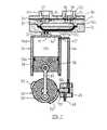
- FIG. 1is a longitudinal cross-section through the pump
- FIG. 2is an exploded view in cross-section of the pump as shown in FIG. 1 ,
- FIG. 3is a transverse cross-sectional view taken between the inlet and outlet ports but showing only two sections of the pump body
- FIG. 4is a perspective view of one housing section of the pump
- FIG. 5is a schematic view of the pump on an exhaust cycle
- FIG. 6is a view similar to FIG. 5 but of the inlet cycle
- FIG. 7is a cross-sectional view of a second embodiment which incorporates a different form of control mechanism
- FIG. 8is a plan view of a first pump body half according to a further embodiment
- FIG. 8Ais an end view of the pump body half of FIG. 8 .
- FIG. 9is a plan view of a second pump body half according to the embodiment of FIG. 8 .
- FIG. 9Ais an end view of the second pump body half of FIG. 9 .
- FIG. 10is a plan view of a membrane for use in the pump of FIGS. 8 to 9A .
- FIG. 11is an end view showing the assembled pump of FIGS. 8 to 10 .
- the pump 10is, according to a preferred embodiment, formed of two housing sections 11 and 12 . When these are assembled together they define an internal pump cavity 13 . Clamped between the housing sections 11 and 12 , as will hereinafter be described, is a membrane 14 which is made from a suitable flexible material.
- the cavity 13is elongate and, as shown in FIG. 4 , each end 15 is complex curved. In cross-section as shown in FIG. 1 , each end is also curved as indicated at 15 . Furthermore, in transverse cross-section as shown in FIG. 3 , the cavity 13 is also of curved cross-section.
- the cavitycurves gently towards its perimeter, in order to reduce the stresses on the membrane during use. The membrane therefore encounters a gentle continuous curved surface as it comes into contact with the cavity wall, rather than a sharp bend which would create stress in the membrane.
- the Applicant's pumpmay use a small pump volume, defined by the volume of the cavity 13 .
- One cycle of the membranepumps this volume of fluid from an inflow port to an outflow port, as will become clear below.
- the pump volumeis less than 20 ml, more preferably less than 10 ml, ideally around 0.5 to 5 ml.
- the pump volumeis in the range 0.5 to 20 ml, more preferably 0.5 to 10 ml, ideally around 0.5 to 5 ml. This low pump volume contributes both to the accuracy of the pump and the long life of the membrane.
- the cavity 13preferably has a small depth. This means that there is a large surface area of the membrane relative to the pump volume.
- the cavity depthmeasured from one side of the cavity to the half way point of the cavity (this depth is marked “D” in FIG. 1 ), may be less than 5 mm, preferably less than 3 mm, ideally around 1 to 3 mm. Again, this small depth contributes both to the accuracy of the pump and the long life of the membrane.
- the cavityis preferably elongate.
- the cavitymay have a length in the range 40 to 100 mm, preferably around 40 to 70 mm.
- the cavitymay have a width in the range 10 to 40 mm, preferably 10 to 20 mm.
- the pump volume and/or cavity dimensionsresult in only a small amount of movement of the membrane from one side of the cavity to the other. This reduces stress on the membrane and therefore contributes to long life of the membrane.
- the ratio of width of the cavity to depth (as defined above) of the cavityis preferably in the range 8:1 to 16:1, more preferably 10:1 to 14:1, ideally around 12:1.
- the Applicanthas found that these ratios, with appropriate shaping of the chamber walls, determine an arc which significantly reduces the stress on the membrane, leading to long membrane life. Lower ratios place excess stress on the membrane, while higher ratios interfere with the efficient working of the bi-stable membrane.
- Housing section 11incorporates a rebate 16 , which effectively results in an upstand or projecting portion 17 .
- the cavity section 13 ais effectively located, at least in part, in the resultant upstanding portion 17 .
- the other housing section 12has a recessed portion 18 with cavity section 13 b extending away from the floor of the recess 18 .
- the projecting portion 17engages snugly within recess 18 .
- the arrangementis such that surface 20 of projecting portion 17 , terminates a distance from the floor 19 of recess 18 .
- this distance D(see FIG. 1 ) is less than the thickness of the membrane 14 . The reason for this gap D will hereinafter become apparent.
- the membrane 14is, in the preferred form of the invention, cut from sheet material.
- the materialis of a type which is compatible with the fluid that is intended to be pumped through the pump 10 .
- the membrane materialis selected such as to be able to withstand the corrosive nature of the fluid.
- the membraneis selected from a food grade material in the event that the pump is to handle a liquid foodstuff.
- the membrane 14is cut in a shape and to a size, which enables it to be snugly fitted into the recess 18 .
- the fact that distance D is less than the thickness of the membrane 14causes the peripheral edge margin portion of the membrane 14 to be sandwiched and securely clamped between opposing surfaces 19 and 20 .
- This clamping forceprovides a secure seal between the two sides of the membrane, preventing fluid from flowing between the two sides.
- One or more sealing elementssuch as O-rings, may be provided to assist with this seal.
- a port 22is formed in the housing section 12 and opens into the cavity section 13 b .
- This port 22can be offset toward one end of the cavity 13 , as shown in the drawings, or else it can be located midway in the length of the cavity 13 .
- a recessed flow path in the form of a narrow groove 22 acan be formed in the wall surface of the cavity section 13 b and extend along the length of the cavity 13 either side of from the port 22 .
- a similar recessed flow path in the form of a narrow groove(not shown) can be formed in cavity 13 b .
- the effect of the recessed flow pathis to prevent the pump from “choking” when the membrane approaches contact with the surface of the cavity. Such contact could prevent fluid flow from occurring and thereby result in the cavity not fully filling or exhausting.
- the recessed flow pathensures that flow occurs right down to when the membrane comes into full overall contact with the cavity surface.
- the recessed flow pathcould be a series of grooves, or lowpoints in a profiled surface (e.g. a ribbed surface, or a roughened surface, or even a surface with projecting pins).
- the recessed flow pathsare believed to contribute to efficient flow of fluid into the cavity, particularly into the cavity from the pressure port.
- a portwhich opens from the cavity 13 to the outer surface 23 of housing section 11 .
- Port 24functions as an inflow or inlet port while port 25 functions as an outflow, outlet or exhaust port.
- Each of inlet ports 24 and exhaust port 25can, as shown, be made up by a plurality of separate passages 24 a and 25 a respectively.
- a recess 26is formed in the surface 23 of housing section 11 and into this is engaged a disk of flexible material which forms valve element 27 .
- a valve element 28 in the form of a disk of flexible materialis provided in the exhaust valve 25 but it locates in a recess 29 in cover 30 .
- Cover 30has connecting pieces 31 and 32 (e.g. in the form of annular walls or turrets) which respectively provide connections for an inlet line (not shown) to inlet valve 24 and an outlet or exhaust line (also not shown) from exhaust valve 25 .
- connecting pieces 31 and 32e.g. in the form of annular walls or turrets
- the membraneis formed from a non-elastomeric material.
- the membraneis formed from a non-elastomeric sheet material, such as a non-elastomeric sheet polymer material.
- the membrane materialis chemically inert and/or resistant to corrosion by chemicals.
- the membranemay be formed from a non-elastomeric fluoropolymer.
- the membranemay be formed from PTFE (polytetrafluoroethylene), PFA (perfluoroalkoxy polymer resin) or FEP (fluorinated ethylene-propylene).
- PTFETeflon
- the membraneis permanently deformed such that the deformed shape of the material conforms to the shape of the opposing surfaces of the pump cavity 13 .
- the membranewill then have a first stable state, in which the membrane lies without further deformation (e.g. extension) against one of the opposing surfaces, and a second stable state, in which the membrane lies without further deformation (e.g. extension) against the other of the opposing surfaces.
- Permanent deformation of the membranemay be achieved by forcing the non-elastic membrane against a shaped surface.
- the Applicant's pumpmay be assembled. A pressure is then applied to the cavity 13 , to force the membrane against one of the cavity's opposing surfaces. This pressure must be sufficiently high to cause the membrane to conform completely to the surface and to permanently deform to this shape, so will generally be significantly greater than an operating pressure of the pump.
- the pressurecan be applied via one or more of the flow ports communicating with the cavity 13 .
- the deformation pressureis around 40 to 50 psi, significantly higher than an operating pressure around 10 to 20 psi.
- This methodhas the advantage that the permanent deformation can be achieved as part of the assembly process.
- the membraneneed be formed only as a section of planar sheet material, with three dimensional permanent deformation occurring in situ after assembly of the pump.
- permanent deformation of the membranemay be achieved by forcing the membrane against a shaped surface before fitting the membrane to the rest of the pump. This shaped surface would be shaped such that the resulting permanently deformed membrane conforms to the shape of the opposing surfaces of the pump cavity 13 .
- the force used in deforming the membranecan be applied by any suitable mechanism. However, pressure is most easily applied by a pressurised fluid, preferably a pressurised gas.
- the membraneis non-elastic but still flexible.
- the membranemay be formed from a sheet material with a thickness in the range 0.002 to 0.025 inches, preferably in the range 0.005 to 0.020 inches, ideally around 0.010 to 0.015 inches. This provides the necessary flexibility to allow the membrane to travel between the two stable states, sufficient stability to cause the membrane to naturally conform to the stable states, allows satisfactory permanent deformation of the membrane as discussed above and provides a durable membrane for long life. Thinner materials tend to lack sufficient stability, while thicker materials are placed under greater stress.
- the permanent deformation of the membranemay be plastic deformation.
- the deformation processmay be carried out at low temperature (e.g. room temperature).
- the permanent deformation of the membranecan be contrasted with other techniques such as injection moulding, which would result in a membrane which sits naturally in only one of the stable states.
- the membrane 14is bi-stable.
- One stable position of the membrane 14is shown in full detail in FIG. 1 while the other stable position is shown in dotted detail.
- the membrane 14in the first stable position the membrane 14 is in the cavity section 13 b and when in the second stable position the membrane 14 is located in the cavity section 13 a.
- the membrane 14adopts a stable position in either a position which conforms with completion of intake of fluid through inlet valve 24 (i.e. the position shown in the drawings) and a full or completed exhaust position.
- a stable positionis a position adopted by the membrane in the absence of applied pressure.
- the Applicant's pumpthere are two such positions as described above.
- the membrane 14is moved between its two stable positions by application of negative P 1 and positive P 2 pressures applied to the cavity 13 b through port 22 . Consequently with the pump in the configuration shown in FIG. 1 and inlet and outlet conduits or lines attached to connectors 31 and 32 a positive pressure P 2 (see FIG. 5 ) applied through port 22 will force the membrane 14 into an opposite stable position.
- a positive pressure P 2(see FIG. 5 ) applied through port 22 will force the membrane 14 into an opposite stable position.
- the inlet valve 24is forced closed while the outlet valve 25 is forced open and any fluid within the cavity 13 i.e. to that side of the membrane opposite to that which faces port 22 , is exhausted through the outlet valve 25 .
- a negative pressure P 1 applied via port 22causes the membrane 14 to return to the position shown in FIG. 1 which also causes the exhaust valve 25 to close but the inlet valve 24 to open and enable fluid in the inlet line to be drawn into cavity 13 .
- the cavity 13thus fills with the fluid ready to be exhausted through the outlet valve 25 upon the next cycle occurring when membrane 14 moves back into cavity section 13 a under positive pressure P 2 .
- the means for applying negative and positive pressurescan take on many forms as will be apparent to the person skilled in the art.
- the meanscould comprise, for example, sources of positive and negative pressure, which via suitable valves can be coupled to the port 22 .
- FIGS. 1 and 7Examples of mechanisms we have developed for applying the positive and negative pressures via port 22 are shown in FIGS. 1 and 7 .
- FIG. 1there is a pneumatic operator 33 that has a body 34 which defines a chamber 35 in which a piston 36 is reciprocally mounted.
- a piston rod 37is pivotally connected via pivot 38 to the piston 36 .
- This piston rod 37is pivotally connected by pivot 39 at its other end to a rotating drive member 40 .
- the drive member 40is connected to a drive means (not shown) which can be in the form of an electric motor or some other form of motive power.
- a port 41 in the end wall 42 of the body 34is in communication with port 22 .
- the body 34is in close proximity to the pump 10 but it will be appreciated by those skilled in the art that the pneumatic operator 33 could be located quite some distance away from the pump 10 and connected by a conduit extending between ports 22 and 41 .
- a recess 43is formed in the inside surface of the side wall 34 a of body 34 .
- the recessis located adjacent the end of wall 42 .
- a port 43 awhich opens to atmosphere.
- the port 43 ais shown in one preferred position where it is adjacent the inner end of the piston 36 when the piston is at its full stroke away from end wall 42 of body 34 .
- the chamber 35is fully vented to atmosphere.
- the position of port 43 acan be varied dependent on use requirements that may require venting before the full stroke of piston 36 has been completed.
- FIG. 7An alternative arrangement is shown in FIG. 7 .
- a port 43 ′ in the wall 34 ais connected to a conduit 44 which is, in turn, connected to a vent housing 45 .
- One wall of the vent housing 45has a vent opening 49 which opens into a chamber 50 in which a pin 51 is moveably located. The pin 51 is therefore moveable between the position where conduit 44 is isolated from vent 49 to a position where the vent 49 is connected to conduit 44 .
- a pair of curved or shaped (e.g. ramped) projections 52 and 53Mounted with a periphery of the driving member 40 and projecting there from is a pair of curved or shaped (e.g. ramped) projections 52 and 53 . Consequently, as the rotating member 40 rotates, a projection 52 or 53 comes into contact pin 51 which forces the pin 51 inwardly (relative to the housing) thereby connecting or disconnecting the vent 49 from the conduit 44 .
- the pin 51is biased by suitable biasing means (not shown) such as a spring or the like into a position where the vent 49 is closed i.e. isolated from conduit 44 .
- vent port 49will still be closed. This will continue to be the situation until the engagement projection 52 comes into contact with pin 51 to effectively open the vent port 49 . As a result, the vent port 49 once again vents the chamber 35 to atmosphere. After the vent 49 is closed from conduit 44 by movement of the pin 51 and as a result of the pin clearing the projection 52 , the continued movement of the piston 36 back to its first position will create a negative pressure.
- the point and the movement of the piston 36 where contact between the pin 51 and projections 53 respectively occursis adjustable.
- projections 52 and 53can be adjustable in position on the periphery of the driving member or rotor 40 so that, for example, the period during which the piston creates a positive pressure could be less. This would result in the time that the membrane is under negative pressure to be greater than the period that it is under positive pressure.
- the bi-stable flexible membrane 14effectively has a small amount of travel between its two states. It is not mechanically connected to any drive thereby giving the membrane free movement in the cavity 13 .
- the cavity shapeis round rectangular and its contoured to fit the bi-stable shape of the membrane. Consequently, the cavity supports the diaphragm over its full surface when the diaphragm is in a so-called stable state.
- the membraneis therefore subject to uniform pressure not only when in the stable states but during the transition between the states as it is supported on both surfaces by the incoming or outgoing pumpable medium and the positive or negative pressure applied across the whole membrane surface via port 22 .
- the pumptherefore provides maximum efficiency and good linear flow characteristics, the latter being more critical as viscosity of the pumpable medium increases.
- the outlet pressurewill be governed by the drive pressure therefore no need for pressure limiting.
- Suction (lift)is governed by the negative pressure. There is thus consistent through put over a wide range of drive pressures.
- valves 24 and 25are located at the half round extremities of the cavity and in close proximity to the cavity. This proximity of the valves to the cavity thus minimises voids thereby giving optimum dry prime and compression ratio.
- the pump arrangementis such that only low inertia needs to be overcome in order to drive the membrane.
- the valvesare progressively closed and finally close before full exhaust or intake. This means that the last thing to occur as the membrane 14 reaches its stable position is movement of the valves into a closed position or opening is the first thing to occur upon the membrane 14 moving from a stable position.
- FIG. 8shows the pressure port side of a pump according to a further embodiment.
- the pump body half 80includes a generally flat surface 81 with a shallow depression 82 which forms one half of the pump cavity in the assembled pump.
- the flat surface 81may have one or more grooves formed therein for receiving one or more O-ring seals to form a sealed connection with the other pump body half 90 .
- the depression 82preferably is dimensioned and shaped as described above and includes a surface feature 84 defining a recessed flow path communicating with the pressure port 85 .
- a number of holes 86may be formed on the flat surface 81 and as will become clear below these aid with correct assembly and alignment of the pump body halves and membrane.
- the pressure port 85is preferably positioned at the top of the chamber, at the same end as the output port.
- the Applicanthas found that the positioning of the pressure port at the same end as the output port actually improves the performance of the pump.
- FIG. 8Ais an end view of the pump body half 80 , looking down from the top. This shows that the pump body half is formed essentially as a half cylinder.
- a connection port 87communicates with the pressure port 85 to allow connection of a positive/negative pressure source to the pump.
- FIG. 9shows the second pump body half 90 .
- This pump body halfincludes a flat surface 91 which will rest against the flat surface 81 of the first pump body half in an assembled pump.
- a depression 92is formed in the flat surface 91 and has a shape matching the shape of the depression 82 in the first pump body half.
- An inflow port 93 and an outflow port 94are formed in the depression, and a recessed flow path is also provided to avoid the “choking” problem described above.
- the inflow port 93is preferably positioned at the bottom of the pump chamber, with the outflow port 94 at the top of the chamber. This helps to ensure that air is not trapped within the chamber, since it will naturally flow towards the outflow port and be removed from the chamber as part of the natural operation of the pump.
- a number of pins 96extend from the flat surface 91 and cooperate with the holes 86 to ensure correct alignment of the two pump body halves 80 , 90 .
- FIG. 9Ais an end view of the top of the second pump body half 90 .
- An outflow connection port 97communicates with the outflow port 94 for connection of an outflow conduit to the pump.
- a similar inflow connection portis provided in the bottom of the second pump body half for connection of an inflow conduit.
- FIG. 10is a plan view of the membrane 100 used in this embodiment, before permanent deformation of the membrane.
- the membrane 100is a flat sheet material with a number of apertures 101 which cooperate with the pins to ensure correct positioning and alignment of the membrane during assembly.
- the membranewill be permanently deformed as described above to match the inner surfaces of the depressions 82 , 92 .
- One or more sealing elementscreate seals between the two flat surfaces 81 , 91 and the membrane so as to close the pump chamber.
- the pump body halvesmay be formed from any suitable material. However, preferably a plastics material is used for ease of manufacture. In addition the material should be resistant to the fluid used to apply pressure and the fluid being pumped. Polypropylene may be suitable for many applications.
- the pump body halvesmay be held together by a cover which slides over the assembled cylinder.
- the covercould clamp around the pump halves, or any suitable fasteners could be used.
- FIGS. 8 to 11may otherwise operate in similar manner to the embodiments of FIGS. 1 to 7 , with valve arrangements, sources of positive and negative pressure etc as described above.
- the Applicant's pumpwill continue to deliver reliable, accurate pumping throughout the long life of the pump.
- the pre-deformation of the membrane, small cavity depth and recessed flow pathsall contribute to reliable and complete travel of the membrane from one stable state in contact with one opposing surface of the cavity to the other stable state in contact with the other opposing surface of the cavity.
- This means that the pump volumeis reliably pumped from the inflow port to the outflow port with each and every cycle of the membrane.
- This accuracyis expected to be retained throughout the long life of the pump, with less than 5% change in accuracy over the life of the device. This is a significant improvement over prior pumps.
- the design of the Applicant's pump housing and membranemeans that only a very low level of power is required to cause motion of the membrane.
- the membraneis pre-deformed, so that input power is efficiently converted into movement of fluid through the pump, not expended in deformation of the membrane. Once motion of the membrane passes a certain point, the pre-deformed membrane tends to move of its own accord into one of its stable states, which is very efficient (despite the fact that this motion is of course resisted by the fluid being pumped).
- the small chamber depthalso means that the distance travelled by the membrane is small.
- the Applicant's pumptherefore operates at around 95% efficiency, which is around 2 to 2.5 times better than most prior devices. This represents a significant saving in ongoing energy consumption and operating cost. In fact the Applicant's pump can be adequately powered of a small number of conventional 1.5V battery cells and has twice the battery life of some prior pumps.
Landscapes
- Engineering & Computer Science (AREA)
- Mechanical Engineering (AREA)
- General Engineering & Computer Science (AREA)
- Reciprocating Pumps (AREA)
Abstract
Description
Claims (23)
Priority Applications (2)
| Application Number | Priority Date | Filing Date | Title |
|---|---|---|---|
| US12/582,665US8454324B2 (en) | 2004-03-18 | 2009-10-20 | Pump |
| US13/875,636US20130243622A1 (en) | 2004-03-18 | 2013-05-02 | Pump |
Applications Claiming Priority (5)
| Application Number | Priority Date | Filing Date | Title |
|---|---|---|---|
| NZ531822 | 2004-03-18 | ||
| NZ531822ANZ531822A (en) | 2004-03-18 | 2004-03-18 | A membrane pump |
| PCT/NZ2005/000046WO2005088128A1 (en) | 2004-03-18 | 2005-03-18 | A membrane pump |
| US10/593,174US20070140873A1 (en) | 2004-03-18 | 2005-03-18 | Pump |
| US12/582,665US8454324B2 (en) | 2004-03-18 | 2009-10-20 | Pump |
Related Parent Applications (3)
| Application Number | Title | Priority Date | Filing Date |
|---|---|---|---|
| PCT/NZ2005/000046Continuation-In-PartWO2005088128A1 (en) | 2004-03-18 | 2005-03-18 | A membrane pump |
| US10/593,174Continuation-In-PartUS20070140873A1 (en) | 2004-03-18 | 2005-03-18 | Pump |
| US11/593,174Continuation-In-PartUS7606952B2 (en) | 2006-11-06 | 2006-11-06 | Method for operating serial flash memory |
Related Child Applications (1)
| Application Number | Title | Priority Date | Filing Date |
|---|---|---|---|
| US13/875,636ContinuationUS20130243622A1 (en) | 2004-03-18 | 2013-05-02 | Pump |
Publications (2)
| Publication Number | Publication Date |
|---|---|
| US20100104458A1 US20100104458A1 (en) | 2010-04-29 |
| US8454324B2true US8454324B2 (en) | 2013-06-04 |
Family
ID=42122907
Family Applications (2)
| Application Number | Title | Priority Date | Filing Date |
|---|---|---|---|
| US12/582,665Active2026-09-12US8454324B2 (en) | 2004-03-18 | 2009-10-20 | Pump |
| US13/875,636AbandonedUS20130243622A1 (en) | 2004-03-18 | 2013-05-02 | Pump |
Family Applications After (1)
| Application Number | Title | Priority Date | Filing Date |
|---|---|---|---|
| US13/875,636AbandonedUS20130243622A1 (en) | 2004-03-18 | 2013-05-02 | Pump |
Country Status (1)
| Country | Link |
|---|---|
| US (2) | US8454324B2 (en) |
Cited By (4)
| Publication number | Priority date | Publication date | Assignee | Title |
|---|---|---|---|---|
| US20150139821A1 (en)* | 2013-11-15 | 2015-05-21 | Invenix, Inc. | Pump chamber including internal surface modifications |
| US10578098B2 (en) | 2005-07-13 | 2020-03-03 | Baxter International Inc. | Medical fluid delivery device actuated via motive fluid |
| US10989185B1 (en)* | 2020-04-03 | 2021-04-27 | Douglas D. Myers | Cover for eccentric pushrod |
| US11478578B2 (en) | 2012-06-08 | 2022-10-25 | Fresenius Medical Care Holdings, Inc. | Medical fluid cassettes and related systems and methods |
Families Citing this family (2)
| Publication number | Priority date | Publication date | Assignee | Title |
|---|---|---|---|---|
| TWI475180B (en)* | 2012-05-31 | 2015-03-01 | Ind Tech Res Inst | Synthetic jet device |
| DK201570293A1 (en)* | 2015-05-19 | 2016-12-12 | Nel Hydrogen As | Diaphragm compressor with an oblong shaped chamber |
Citations (72)
| Publication number | Priority date | Publication date | Assignee | Title |
|---|---|---|---|---|
| US1005270A (en) | 1910-06-07 | 1911-10-10 | Joseph Milburn | Pump. |
| FR787226A (en) | 1934-06-13 | 1935-09-19 | Improvement in compressors or diaphragm pumps | |
| US2762395A (en)* | 1953-08-20 | 1956-09-11 | Lamb Rubber Corp | Inflatable diaphragm for hydraulic presses |
| US2821930A (en) | 1953-06-12 | 1958-02-04 | Ici Ltd | Diaphragm operated delivery pumps |
| US2902936A (en) | 1955-03-17 | 1959-09-08 | Kontak Mfg Co Ltd | Pumps for metering liquids |
| US3000320A (en)* | 1957-07-18 | 1961-09-19 | Ring Sandiford | Pump |
| US3006306A (en)* | 1956-02-07 | 1961-10-31 | Gen Tire & Rubber Co | Hydraulic press |
| US3093086A (en)* | 1960-04-12 | 1963-06-11 | Westinghouse Electric Corp | Diaphragm assemblage |
| US3094074A (en)* | 1960-12-27 | 1963-06-18 | Walbro Corp | Bladder fuel pump |
| US3101058A (en) | 1961-06-16 | 1963-08-20 | Jr William H Carr | Diaphragm pumping system |
| US3124078A (en)* | 1964-03-10 | hardy | ||
| US3294031A (en) | 1965-07-28 | 1966-12-27 | Stephen H Latawic | Fluid motor system |
| US3314371A (en) | 1965-09-22 | 1967-04-18 | St Barnabas Free Home Inc | Diaphragm pump |
| US3338171A (en)* | 1965-09-15 | 1967-08-29 | Du Pont | Pneumatically operable diaphragm pumps |
| US3357360A (en) | 1965-11-22 | 1967-12-12 | Purex Corp Ltd | Hydraulic pumping system |
| US3431823A (en) | 1965-12-16 | 1969-03-11 | Franz Orlita | Diaphragm assembly for a diaphragm pump |
| US3460482A (en) | 1968-01-29 | 1969-08-12 | Purex Corp Ltd | Pumping mechanisms |
| US3485258A (en) | 1966-04-14 | 1969-12-23 | Greene Eng Co | Bistable fluid device |
| US3503307A (en) | 1967-03-31 | 1970-03-31 | I V Pressure Controllers Ltd | Diaphragms |
| US3689719A (en) | 1971-09-13 | 1972-09-05 | Dwyer Instr | Fluid pressure operated diaphragm switch with improved adjustment means and contact structure |
| US3900276A (en) | 1973-05-16 | 1975-08-19 | Mcculloch Corp | Diaphragm pump method and apparatus |
| US3947156A (en) | 1972-03-08 | 1976-03-30 | Erich Becker | Diaphragm pump, particularly for the generation of vacuum |
| US3955901A (en)* | 1973-10-23 | 1976-05-11 | Hamilton Thomas W | Membrane pump |
| US4021164A (en) | 1974-10-16 | 1977-05-03 | Ab Piab | Pump having reciprocating pumping means |
| US4090964A (en)* | 1977-07-21 | 1978-05-23 | Ecodyne Corporation | Acid dispenser for water softener unit |
| US4124008A (en) | 1975-12-05 | 1978-11-07 | Kawasaki Jukogyo Kabushiki Kaisha | Integrated fuel supply system for an internal combustion engine including filter, valve, and pump |
| US4181245A (en)* | 1978-02-17 | 1980-01-01 | Baxter Travenol Laboratories, Inc. | Casette for use with an I.V. infusion controller |
| US4261356A (en) | 1978-10-23 | 1981-04-14 | Baxter Travenol Laboratories, Inc. | Method and apparatus for controlling the dispensing of fluid |
| US4304260A (en) | 1979-11-01 | 1981-12-08 | Turner Charles R | Flexible diaphragm valve device |
| US4430048A (en) | 1980-12-29 | 1984-02-07 | Lewa Herbert Ott Gmbh & Co. | Diaphragm pump with a diaphragm clamped in pressure-balancing arrangement |
| US4437823A (en) | 1979-03-13 | 1984-03-20 | Upravlenie Sanitarno-Tekhnicheskikh Rabot | Rotary machine with an axially moving partition |
| US4486190A (en)* | 1982-12-27 | 1984-12-04 | Consolidated Controls Corporation | Precision medication dispensing system and method |
| US4492013A (en)* | 1980-02-27 | 1985-01-08 | Hydro Rene Leduc | Method for manufacturing a prestressed hydraulic accumulator |
| US4573885A (en) | 1984-04-13 | 1986-03-04 | Bran & Lubbe Gmbh | Piston diaphragm pump |
| US4627256A (en) | 1979-12-26 | 1986-12-09 | Hughes Aircraft Company | Method of forming precisely curved surfaces |
| US4634430A (en)* | 1984-03-07 | 1987-01-06 | Fresenius Ag | Pump arrangement for medical purposes |
| US4718893A (en)* | 1986-02-03 | 1988-01-12 | University Of Minnesota | Pressure regulated implantable infusion pump |
| US4755111A (en)* | 1986-06-11 | 1988-07-05 | Nuovopignone Industrie Meccaniche E Fonderia S.P.A. | Pumping device, particularly suitable for compressing fluids on deep sea-bottoms |
| US4863066A (en) | 1986-06-02 | 1989-09-05 | Technicon Instruments Corporation | System for dispensing precisely metered quantities of a fluid and method of utilizing the system |
| US4904167A (en)* | 1987-02-26 | 1990-02-27 | Karl Eickmann | Membranes and neighboring members in pumps, compressors and devices |
| US4915017A (en)* | 1987-10-26 | 1990-04-10 | D. F. Laboratories Ltd. | Diaphragm and a diaphragm-actuated fluid-transfer control device |
| US4936758A (en)* | 1987-08-10 | 1990-06-26 | Aci Medical, Inc. | Diaphragm pump |
| US4995864A (en)* | 1989-08-15 | 1991-02-26 | Imed Corporation | Dual chamber pumping apparatus |
| US5002471A (en) | 1987-07-20 | 1991-03-26 | D.F. Laboratories Ltd. | Disposable cell and diaphragm pump for use of same |
| US5018949A (en)* | 1989-02-02 | 1991-05-28 | Uraca Pumpenfabrik Gmbh & Co. Kg | Diaphragm pump |
| US5088515A (en)* | 1989-05-01 | 1992-02-18 | Kamen Dean L | Valve system with removable fluid interface |
| US5165869A (en)* | 1991-01-16 | 1992-11-24 | Warren Rupp, Inc. | Diaphragm pump |
| US5244360A (en)* | 1990-12-18 | 1993-09-14 | Dosapro Milton Roy | Hydraulically controlled diaphragm pump for high pressures |
| US5367878A (en)* | 1991-11-08 | 1994-11-29 | University Of Southern California | Transient energy release microdevices and methods |
| US5423738A (en) | 1992-03-13 | 1995-06-13 | Robinson; Thomas C. | Blood pumping and processing system |
| US5458468A (en)* | 1988-12-29 | 1995-10-17 | Victor Peter Chang | Diaphragm pump |
| US5499909A (en)* | 1993-11-17 | 1996-03-19 | Aisin Seiki Kabushiki Kaisha Of Kariya | Pneumatically driven micro-pump |
| US5669764A (en)* | 1994-10-07 | 1997-09-23 | Bayer Corporation | Pneumatic diaphragm pump |
| US5836750A (en) | 1997-10-09 | 1998-11-17 | Honeywell Inc. | Electrostatically actuated mesopump having a plurality of elementary cells |
| WO1999001687A1 (en) | 1997-07-03 | 1999-01-14 | Precision Dispensing Systems Limited | A flexible tube pinch mechanism |
| US6105829A (en)* | 1989-03-28 | 2000-08-22 | Millipore Investment Holdings, Ltd. | Fluid dispensing system |
| US6132187A (en)* | 1999-02-18 | 2000-10-17 | Ericson; Paul Leonard | Flex-actuated bistable dome pump |
| US6190565B1 (en)* | 1993-05-17 | 2001-02-20 | David C. Bailey | Dual stage pump system with pre-stressed diaphragms and reservoir |
| US6273687B1 (en)* | 1998-11-26 | 2001-08-14 | Aisin Seiki Kabushiki Kaisha | Micromachined pump apparatus |
| WO2002018790A1 (en) | 2000-08-28 | 2002-03-07 | Precision Dispensing Systems Limited | Pneumatic pinch mechanism for a deformable tube |
| US6464474B2 (en)* | 2000-03-16 | 2002-10-15 | Lewa Herbert Ott Gmbh + Co. | Nonrespiratory diaphragm chucking |
| US6474961B1 (en)* | 1999-09-29 | 2002-11-05 | Oliver Timmer | Compact dual diaphragm pump |
| US6484383B1 (en)* | 1998-03-30 | 2002-11-26 | Fresenius Medical Care Deutschland Gmbh | Method of airtight bonding of two membranes |
| US6582206B2 (en)* | 2000-03-16 | 2003-06-24 | Lewa Herbert Ott Gmbh + Co. | Diaphragm chucking with elasticity adjustment |
| US20030194332A1 (en)* | 2002-04-12 | 2003-10-16 | Bayer Aktiengesellschaft | Diaphragm pump |
| US6669455B2 (en) | 2002-01-31 | 2003-12-30 | Elmer Scott Welch | Fluid-pumping system employing air-driven pump and employing at least one pulsation dampener |
| US6705841B2 (en)* | 2002-03-01 | 2004-03-16 | Visteon Global Technologies, Inc. | Variable displacement compressor with stepped shaft |
| US20040109769A1 (en)* | 2002-04-12 | 2004-06-10 | Bayer Aktiengesellschaft | Diaphragm pump |
| US6749403B2 (en)* | 1999-07-20 | 2004-06-15 | Deka Products Limited Partnership | Methods for controlling a pump's flow rate by pulsed discharge |
| US20050074340A1 (en)* | 2003-10-01 | 2005-04-07 | Agency For Science, Technology And Research | Micro-pump |
| US6971859B2 (en)* | 2003-11-28 | 2005-12-06 | Kabushiki Kaisha Toyota Jidoshokki | Diaphragm unit |
| US7942647B2 (en) | 2004-11-01 | 2011-05-17 | Octec Inc. | Pump for supplying chemical liquids |
Family Cites Families (1)
| Publication number | Priority date | Publication date | Assignee | Title |
|---|---|---|---|---|
| FR2828245B1 (en)* | 2001-04-27 | 2005-11-11 | Poudres & Explosifs Ste Nale | PYROTECHNIC MICROSYSTEMS FOR MICROSYSTEMS |
- 2009
- 2009-10-20USUS12/582,665patent/US8454324B2/enactiveActive
- 2013
- 2013-05-02USUS13/875,636patent/US20130243622A1/ennot_activeAbandoned
Patent Citations (80)
| Publication number | Priority date | Publication date | Assignee | Title |
|---|---|---|---|---|
| US3124078A (en)* | 1964-03-10 | hardy | ||
| US1005270A (en) | 1910-06-07 | 1911-10-10 | Joseph Milburn | Pump. |
| FR787226A (en) | 1934-06-13 | 1935-09-19 | Improvement in compressors or diaphragm pumps | |
| US2821930A (en) | 1953-06-12 | 1958-02-04 | Ici Ltd | Diaphragm operated delivery pumps |
| US2762395A (en)* | 1953-08-20 | 1956-09-11 | Lamb Rubber Corp | Inflatable diaphragm for hydraulic presses |
| US2902936A (en) | 1955-03-17 | 1959-09-08 | Kontak Mfg Co Ltd | Pumps for metering liquids |
| US3006306A (en)* | 1956-02-07 | 1961-10-31 | Gen Tire & Rubber Co | Hydraulic press |
| US3000320A (en)* | 1957-07-18 | 1961-09-19 | Ring Sandiford | Pump |
| US3093086A (en)* | 1960-04-12 | 1963-06-11 | Westinghouse Electric Corp | Diaphragm assemblage |
| US3094074A (en)* | 1960-12-27 | 1963-06-18 | Walbro Corp | Bladder fuel pump |
| US3101058A (en) | 1961-06-16 | 1963-08-20 | Jr William H Carr | Diaphragm pumping system |
| US3294031A (en) | 1965-07-28 | 1966-12-27 | Stephen H Latawic | Fluid motor system |
| US3338171A (en)* | 1965-09-15 | 1967-08-29 | Du Pont | Pneumatically operable diaphragm pumps |
| US3314371A (en) | 1965-09-22 | 1967-04-18 | St Barnabas Free Home Inc | Diaphragm pump |
| US3357360A (en) | 1965-11-22 | 1967-12-12 | Purex Corp Ltd | Hydraulic pumping system |
| US3431823A (en) | 1965-12-16 | 1969-03-11 | Franz Orlita | Diaphragm assembly for a diaphragm pump |
| US3485258A (en) | 1966-04-14 | 1969-12-23 | Greene Eng Co | Bistable fluid device |
| US3503307A (en) | 1967-03-31 | 1970-03-31 | I V Pressure Controllers Ltd | Diaphragms |
| US3460482A (en) | 1968-01-29 | 1969-08-12 | Purex Corp Ltd | Pumping mechanisms |
| US3689719A (en) | 1971-09-13 | 1972-09-05 | Dwyer Instr | Fluid pressure operated diaphragm switch with improved adjustment means and contact structure |
| US3947156A (en) | 1972-03-08 | 1976-03-30 | Erich Becker | Diaphragm pump, particularly for the generation of vacuum |
| US3900276A (en) | 1973-05-16 | 1975-08-19 | Mcculloch Corp | Diaphragm pump method and apparatus |
| US3955901A (en)* | 1973-10-23 | 1976-05-11 | Hamilton Thomas W | Membrane pump |
| US4021164A (en) | 1974-10-16 | 1977-05-03 | Ab Piab | Pump having reciprocating pumping means |
| US4124008A (en) | 1975-12-05 | 1978-11-07 | Kawasaki Jukogyo Kabushiki Kaisha | Integrated fuel supply system for an internal combustion engine including filter, valve, and pump |
| US4090964A (en)* | 1977-07-21 | 1978-05-23 | Ecodyne Corporation | Acid dispenser for water softener unit |
| US4181245A (en)* | 1978-02-17 | 1980-01-01 | Baxter Travenol Laboratories, Inc. | Casette for use with an I.V. infusion controller |
| US4261356A (en) | 1978-10-23 | 1981-04-14 | Baxter Travenol Laboratories, Inc. | Method and apparatus for controlling the dispensing of fluid |
| US4437823A (en) | 1979-03-13 | 1984-03-20 | Upravlenie Sanitarno-Tekhnicheskikh Rabot | Rotary machine with an axially moving partition |
| US4304260A (en) | 1979-11-01 | 1981-12-08 | Turner Charles R | Flexible diaphragm valve device |
| US4627256A (en) | 1979-12-26 | 1986-12-09 | Hughes Aircraft Company | Method of forming precisely curved surfaces |
| US4492013A (en)* | 1980-02-27 | 1985-01-08 | Hydro Rene Leduc | Method for manufacturing a prestressed hydraulic accumulator |
| US4430048A (en) | 1980-12-29 | 1984-02-07 | Lewa Herbert Ott Gmbh & Co. | Diaphragm pump with a diaphragm clamped in pressure-balancing arrangement |
| US4486190A (en)* | 1982-12-27 | 1984-12-04 | Consolidated Controls Corporation | Precision medication dispensing system and method |
| US4634430A (en)* | 1984-03-07 | 1987-01-06 | Fresenius Ag | Pump arrangement for medical purposes |
| US4573885A (en) | 1984-04-13 | 1986-03-04 | Bran & Lubbe Gmbh | Piston diaphragm pump |
| US4718893A (en)* | 1986-02-03 | 1988-01-12 | University Of Minnesota | Pressure regulated implantable infusion pump |
| US4863066A (en) | 1986-06-02 | 1989-09-05 | Technicon Instruments Corporation | System for dispensing precisely metered quantities of a fluid and method of utilizing the system |
| US4755111A (en)* | 1986-06-11 | 1988-07-05 | Nuovopignone Industrie Meccaniche E Fonderia S.P.A. | Pumping device, particularly suitable for compressing fluids on deep sea-bottoms |
| US4904167A (en)* | 1987-02-26 | 1990-02-27 | Karl Eickmann | Membranes and neighboring members in pumps, compressors and devices |
| US5002471A (en) | 1987-07-20 | 1991-03-26 | D.F. Laboratories Ltd. | Disposable cell and diaphragm pump for use of same |
| US4936758A (en)* | 1987-08-10 | 1990-06-26 | Aci Medical, Inc. | Diaphragm pump |
| US4915017A (en)* | 1987-10-26 | 1990-04-10 | D. F. Laboratories Ltd. | Diaphragm and a diaphragm-actuated fluid-transfer control device |
| EP0314379B1 (en) | 1987-10-26 | 1991-08-21 | D.F. Laboratories Ltd. | A diaphragm and a diaphragm-actuated fluid-transfer control device |
| US5458468A (en)* | 1988-12-29 | 1995-10-17 | Victor Peter Chang | Diaphragm pump |
| US5018949A (en)* | 1989-02-02 | 1991-05-28 | Uraca Pumpenfabrik Gmbh & Co. Kg | Diaphragm pump |
| US6251293B1 (en) | 1989-03-28 | 2001-06-26 | Millipore Investment Holdings, Ltd. | Fluid dispensing system having independently operated pumps |
| US6105829A (en)* | 1989-03-28 | 2000-08-22 | Millipore Investment Holdings, Ltd. | Fluid dispensing system |
| US5088515A (en)* | 1989-05-01 | 1992-02-18 | Kamen Dean L | Valve system with removable fluid interface |
| US4995864A (en)* | 1989-08-15 | 1991-02-26 | Imed Corporation | Dual chamber pumping apparatus |
| US5244360A (en)* | 1990-12-18 | 1993-09-14 | Dosapro Milton Roy | Hydraulically controlled diaphragm pump for high pressures |
| US5165869A (en)* | 1991-01-16 | 1992-11-24 | Warren Rupp, Inc. | Diaphragm pump |
| US5367878A (en)* | 1991-11-08 | 1994-11-29 | University Of Southern California | Transient energy release microdevices and methods |
| US5423738A (en) | 1992-03-13 | 1995-06-13 | Robinson; Thomas C. | Blood pumping and processing system |
| US6190565B1 (en)* | 1993-05-17 | 2001-02-20 | David C. Bailey | Dual stage pump system with pre-stressed diaphragms and reservoir |
| US5499909A (en)* | 1993-11-17 | 1996-03-19 | Aisin Seiki Kabushiki Kaisha Of Kariya | Pneumatically driven micro-pump |
| US5669764A (en)* | 1994-10-07 | 1997-09-23 | Bayer Corporation | Pneumatic diaphragm pump |
| US5902096A (en)* | 1994-10-07 | 1999-05-11 | Bayer Corporation | Diaphragm pump having multiple rigid layers with inlet and outlet check valves |
| US20020047099A1 (en)* | 1997-07-03 | 2002-04-25 | Grapes Robert Donald | Flexible tube pinch mechanism |
| US6554589B2 (en)* | 1997-07-03 | 2003-04-29 | Precision Dispensing Systems Limited | Flexible tube pinch mechanism |
| WO1999001687A1 (en) | 1997-07-03 | 1999-01-14 | Precision Dispensing Systems Limited | A flexible tube pinch mechanism |
| US5836750A (en) | 1997-10-09 | 1998-11-17 | Honeywell Inc. | Electrostatically actuated mesopump having a plurality of elementary cells |
| US6484383B1 (en)* | 1998-03-30 | 2002-11-26 | Fresenius Medical Care Deutschland Gmbh | Method of airtight bonding of two membranes |
| US6273687B1 (en)* | 1998-11-26 | 2001-08-14 | Aisin Seiki Kabushiki Kaisha | Micromachined pump apparatus |
| US6132187A (en)* | 1999-02-18 | 2000-10-17 | Ericson; Paul Leonard | Flex-actuated bistable dome pump |
| US6749403B2 (en)* | 1999-07-20 | 2004-06-15 | Deka Products Limited Partnership | Methods for controlling a pump's flow rate by pulsed discharge |
| US6474961B1 (en)* | 1999-09-29 | 2002-11-05 | Oliver Timmer | Compact dual diaphragm pump |
| US6464474B2 (en)* | 2000-03-16 | 2002-10-15 | Lewa Herbert Ott Gmbh + Co. | Nonrespiratory diaphragm chucking |
| US6582206B2 (en)* | 2000-03-16 | 2003-06-24 | Lewa Herbert Ott Gmbh + Co. | Diaphragm chucking with elasticity adjustment |
| US20040009081A1 (en)* | 2000-08-28 | 2004-01-15 | Grapes Robert Donald | Pneumatic pinch mechanism for a deformable tube |
| WO2002018790A1 (en) | 2000-08-28 | 2002-03-07 | Precision Dispensing Systems Limited | Pneumatic pinch mechanism for a deformable tube |
| US6887047B2 (en)* | 2000-08-28 | 2005-05-03 | Precision Dispensing Systems Limited | Pneumatic pinch mechanism for a deformable tube |
| US6669455B2 (en) | 2002-01-31 | 2003-12-30 | Elmer Scott Welch | Fluid-pumping system employing air-driven pump and employing at least one pulsation dampener |
| US6705841B2 (en)* | 2002-03-01 | 2004-03-16 | Visteon Global Technologies, Inc. | Variable displacement compressor with stepped shaft |
| US20030194332A1 (en)* | 2002-04-12 | 2003-10-16 | Bayer Aktiengesellschaft | Diaphragm pump |
| US20040109769A1 (en)* | 2002-04-12 | 2004-06-10 | Bayer Aktiengesellschaft | Diaphragm pump |
| US20050074340A1 (en)* | 2003-10-01 | 2005-04-07 | Agency For Science, Technology And Research | Micro-pump |
| US7284966B2 (en) | 2003-10-01 | 2007-10-23 | Agency For Science, Technology & Research | Micro-pump |
| US6971859B2 (en)* | 2003-11-28 | 2005-12-06 | Kabushiki Kaisha Toyota Jidoshokki | Diaphragm unit |
| US7942647B2 (en) | 2004-11-01 | 2011-05-17 | Octec Inc. | Pump for supplying chemical liquids |
Non-Patent Citations (5)
| Title |
|---|
| Final Office Action dated Dec. 24, 2009, U.S. Appl. No. 10/593,174, filed Sep. 15, 2006, 14 pgs. |
| Final Office Action dated Nov. 14, 2008, U.S. Appl. No. 10/593,174, filed Sep. 15, 2006, 10 pgs. |
| Non-Final Office Action dated Jun. 4, 2008, U.S. Appl. No. 10/593,174, filed Sep. 15, 2006, 14 pgs. |
| Non-Final Office Action dated May 1, 2009, U.S. Appl. No. 10/593,174, filed Sep. 15, 2006, 12 pgs. |
| Precision Dispensing Systems Ltd, European Search Report mailed Apr. 18, 2012; EP Appln No. 05722117.8. |
Cited By (10)
| Publication number | Priority date | Publication date | Assignee | Title |
|---|---|---|---|---|
| US10578098B2 (en) | 2005-07-13 | 2020-03-03 | Baxter International Inc. | Medical fluid delivery device actuated via motive fluid |
| US10590924B2 (en) | 2005-07-13 | 2020-03-17 | Baxter International Inc. | Medical fluid pumping system including pump and machine chassis mounting regime |
| US10670005B2 (en) | 2005-07-13 | 2020-06-02 | Baxter International Inc. | Diaphragm pumps and pumping systems |
| US11384748B2 (en) | 2005-07-13 | 2022-07-12 | Baxter International Inc. | Blood treatment system having pulsatile blood intake |
| US12392335B2 (en) | 2005-07-13 | 2025-08-19 | Baxter International Inc. | Medical fluid pumping system having backflow prevention |
| US11478578B2 (en) | 2012-06-08 | 2022-10-25 | Fresenius Medical Care Holdings, Inc. | Medical fluid cassettes and related systems and methods |
| US20150139821A1 (en)* | 2013-11-15 | 2015-05-21 | Invenix, Inc. | Pump chamber including internal surface modifications |
| US10156231B2 (en)* | 2013-11-15 | 2018-12-18 | Ivenix, Inc. | Pump chamber including internal surface modifications |
| AU2014348695B2 (en)* | 2013-11-15 | 2019-05-16 | Fresenius Kabi Usa, Llc | Pump chamber including internal surface modifications |
| US10989185B1 (en)* | 2020-04-03 | 2021-04-27 | Douglas D. Myers | Cover for eccentric pushrod |
Also Published As
| Publication number | Publication date |
|---|---|
| US20100104458A1 (en) | 2010-04-29 |
| US20130243622A1 (en) | 2013-09-19 |
Similar Documents
| Publication | Publication Date | Title |
|---|---|---|
| US20130243622A1 (en) | Pump | |
| US7390175B2 (en) | Double action simplex plunger pump | |
| US5664940A (en) | Gas driven pump | |
| AU2005220568B2 (en) | A membrane pump | |
| US7399168B1 (en) | Air driven diaphragm pump | |
| US8967036B2 (en) | Valve and diaphragm for a pump | |
| US20070092385A1 (en) | Pump and valve actuator system and method | |
| AU2003266350A1 (en) | Micropump and method for the production thereof | |
| CN112196759A (en) | Pulse water pump and tooth washing device | |
| CN113931833B (en) | Valve seat mechanism and miniature electric diaphragm pump | |
| US4480969A (en) | Fluid operated double acting diaphragm pump housing and method | |
| CN118815697A (en) | A dual-drive diaphragm pump | |
| CN219672817U (en) | Diaphragm water pump | |
| US7367785B2 (en) | Reduced icing valves and gas-driven motor and reciprocating pump incorporating same | |
| US8287249B2 (en) | Two-stage membrane pump with economical inlet port design | |
| CN222596254U (en) | Air pump with integrated inlet and outlet valves | |
| CN212177340U (en) | Pulse water pump and tooth washing device | |
| CN218439698U (en) | Leather cup, pump head and pump | |
| CN212360119U (en) | Diaphragm pump runner seal structure | |
| CN216518546U (en) | A New Piezoelectric Pump with Semi-closed Arc Valve Plate | |
| CN110608156A (en) | micro fluid pump | |
| US20240410352A1 (en) | Squeezing peristaltic pump for continuous transfer, and fluid transfer method | |
| CN114893384A (en) | Leather cup, pump head and pump | |
| CN1165549A (en) | Pump and method of manufacturing same | |
| CN115722562A (en) | A gas-hydraulic pressurized drive clamping mechanism and a mold quick clamping system including it |
Legal Events
| Date | Code | Title | Description |
|---|---|---|---|
| AS | Assignment | Owner name:PRECISION DISPENSING SYSTEMS LIMITED,NEW ZEALAND Free format text:ASSIGNMENT OF ASSIGNORS INTEREST;ASSIGNOR:GRAPES, ROBERT DONALD;REEL/FRAME:023749/0607 Effective date:20091104 Owner name:PRECISION DISPENSING SYSTEMS LIMITED, NEW ZEALAND Free format text:ASSIGNMENT OF ASSIGNORS INTEREST;ASSIGNOR:GRAPES, ROBERT DONALD;REEL/FRAME:023749/0607 Effective date:20091104 | |
| STCF | Information on status: patent grant | Free format text:PATENTED CASE | |
| CC | Certificate of correction | ||
| REMI | Maintenance fee reminder mailed | ||
| AS | Assignment | Owner name:MARK IT SOLUTIONS LIMITED, NEW ZEALAND Free format text:ASSIGNMENT OF ASSIGNORS INTEREST;ASSIGNOR:PRECISION DISPENSING SYSTEMS LIMITED;REEL/FRAME:041045/0301 Effective date:20161019 | |
| FPAY | Fee payment | Year of fee payment:4 | |
| SULP | Surcharge for late payment | ||
| MAFP | Maintenance fee payment | Free format text:PAYMENT OF MAINTENANCE FEE, 8TH YR, SMALL ENTITY (ORIGINAL EVENT CODE: M2552); ENTITY STATUS OF PATENT OWNER: SMALL ENTITY Year of fee payment:8 | |
| MAFP | Maintenance fee payment | Free format text:PAYMENT OF MAINTENANCE FEE, 12TH YR, SMALL ENTITY (ORIGINAL EVENT CODE: M2553); ENTITY STATUS OF PATENT OWNER: SMALL ENTITY Year of fee payment:12 | |
| AS | Assignment | Owner name:INFLEX INTERNATIONAL LIMITED, NEW ZEALAND Free format text:CHANGE OF NAME;ASSIGNOR:MARK IT SOLUTIONS LIMITED;REEL/FRAME:069516/0450 Effective date:20170321 Owner name:RUTHERFORDS TRUSTEE COMPANY LIMITED, NEW ZEALAND Free format text:ASSIGNMENT OF ASSIGNORS INTEREST;ASSIGNOR:INFLEX INTERNATIONAL LIMITED;REEL/FRAME:069495/0911 Effective date:20241129 Owner name:BELL-BOOTH, SUSAN MARGARET, NEW ZEALAND Free format text:ASSIGNMENT OF ASSIGNORS INTEREST;ASSIGNOR:INFLEX INTERNATIONAL LIMITED;REEL/FRAME:069495/0911 Effective date:20241129 Owner name:BELL-BOOTH, MARK REX, NEW ZEALAND Free format text:ASSIGNMENT OF ASSIGNORS INTEREST;ASSIGNOR:INFLEX INTERNATIONAL LIMITED;REEL/FRAME:069495/0911 Effective date:20241129 |