US8453962B2 - Modular flying vehicle - Google Patents
Modular flying vehicleDownload PDFInfo
- Publication number
- US8453962B2 US8453962B2US12/070,669US7066908AUS8453962B2US 8453962 B2US8453962 B2US 8453962B2US 7066908 AUS7066908 AUS 7066908AUS 8453962 B2US8453962 B2US 8453962B2
- Authority
- US
- United States
- Prior art keywords
- propeller
- airframe
- flight
- pair
- vehicle
- Prior art date
- Legal status (The legal status is an assumption and is not a legal conclusion. Google has not performed a legal analysis and makes no representation as to the accuracy of the status listed.)
- Expired - Fee Related, expires
Links
Images


Classifications
- B—PERFORMING OPERATIONS; TRANSPORTING
- B64—AIRCRAFT; AVIATION; COSMONAUTICS
- B64C—AEROPLANES; HELICOPTERS
- B64C27/00—Rotorcraft; Rotors peculiar thereto
- B64C27/22—Compound rotorcraft, i.e. aircraft using in flight the features of both aeroplane and rotorcraft
- B64C27/28—Compound rotorcraft, i.e. aircraft using in flight the features of both aeroplane and rotorcraft with forward-propulsion propellers pivotable to act as lifting rotors
- B—PERFORMING OPERATIONS; TRANSPORTING
- B64—AIRCRAFT; AVIATION; COSMONAUTICS
- B64C—AEROPLANES; HELICOPTERS
- B64C27/00—Rotorcraft; Rotors peculiar thereto
- B64C27/04—Helicopters
- B64C27/08—Helicopters with two or more rotors
- B—PERFORMING OPERATIONS; TRANSPORTING
- B64—AIRCRAFT; AVIATION; COSMONAUTICS
- B64C—AEROPLANES; HELICOPTERS
- B64C27/00—Rotorcraft; Rotors peculiar thereto
- B64C27/20—Rotorcraft characterised by having shrouded rotors, e.g. flying platforms
- B—PERFORMING OPERATIONS; TRANSPORTING
- B64—AIRCRAFT; AVIATION; COSMONAUTICS
- B64C—AEROPLANES; HELICOPTERS
- B64C27/00—Rotorcraft; Rotors peculiar thereto
- B64C27/52—Tilting of rotor bodily relative to fuselage
- B—PERFORMING OPERATIONS; TRANSPORTING
- B64—AIRCRAFT; AVIATION; COSMONAUTICS
- B64C—AEROPLANES; HELICOPTERS
- B64C29/00—Aircraft capable of landing or taking-off vertically, e.g. vertical take-off and landing [VTOL] aircraft
- B64C29/0008—Aircraft capable of landing or taking-off vertically, e.g. vertical take-off and landing [VTOL] aircraft having its flight directional axis horizontal when grounded
- B64C29/0016—Aircraft capable of landing or taking-off vertically, e.g. vertical take-off and landing [VTOL] aircraft having its flight directional axis horizontal when grounded the lift during taking-off being created by free or ducted propellers or by blowers
- B64C29/0033—Aircraft capable of landing or taking-off vertically, e.g. vertical take-off and landing [VTOL] aircraft having its flight directional axis horizontal when grounded the lift during taking-off being created by free or ducted propellers or by blowers the propellers being tiltable relative to the fuselage
- B—PERFORMING OPERATIONS; TRANSPORTING
- B64—AIRCRAFT; AVIATION; COSMONAUTICS
- B64U—UNMANNED AERIAL VEHICLES [UAV]; EQUIPMENT THEREFOR
- B64U10/00—Type of UAV
- B64U10/10—Rotorcrafts
- B64U10/13—Flying platforms
- B—PERFORMING OPERATIONS; TRANSPORTING
- B64—AIRCRAFT; AVIATION; COSMONAUTICS
- B64U—UNMANNED AERIAL VEHICLES [UAV]; EQUIPMENT THEREFOR
- B64U10/00—Type of UAV
- B64U10/20—Vertical take-off and landing [VTOL] aircraft
- B—PERFORMING OPERATIONS; TRANSPORTING
- B64—AIRCRAFT; AVIATION; COSMONAUTICS
- B64U—UNMANNED AERIAL VEHICLES [UAV]; EQUIPMENT THEREFOR
- B64U10/00—Type of UAV
- B64U10/60—Tethered aircraft
- B—PERFORMING OPERATIONS; TRANSPORTING
- B64—AIRCRAFT; AVIATION; COSMONAUTICS
- B64U—UNMANNED AERIAL VEHICLES [UAV]; EQUIPMENT THEREFOR
- B64U30/00—Means for producing lift; Empennages; Arrangements thereof
- B64U30/10—Wings
- B—PERFORMING OPERATIONS; TRANSPORTING
- B64—AIRCRAFT; AVIATION; COSMONAUTICS
- B64U—UNMANNED AERIAL VEHICLES [UAV]; EQUIPMENT THEREFOR
- B64U40/00—On-board mechanical arrangements for adjusting control surfaces or rotors; On-board mechanical arrangements for in-flight adjustment of the base configuration
- B64U40/20—On-board mechanical arrangements for adjusting control surfaces or rotors; On-board mechanical arrangements for in-flight adjustment of the base configuration for in-flight adjustment of the base configuration
- B—PERFORMING OPERATIONS; TRANSPORTING
- B64—AIRCRAFT; AVIATION; COSMONAUTICS
- B64U—UNMANNED AERIAL VEHICLES [UAV]; EQUIPMENT THEREFOR
- B64U50/00—Propulsion; Power supply
- B64U50/10—Propulsion
- B64U50/13—Propulsion using external fans or propellers
- B—PERFORMING OPERATIONS; TRANSPORTING
- B64—AIRCRAFT; AVIATION; COSMONAUTICS
- B64U—UNMANNED AERIAL VEHICLES [UAV]; EQUIPMENT THEREFOR
- B64U80/00—Transport or storage specially adapted for UAVs
- B64U80/80—Transport or storage specially adapted for UAVs by vehicles
- B—PERFORMING OPERATIONS; TRANSPORTING
- B64—AIRCRAFT; AVIATION; COSMONAUTICS
- B64U—UNMANNED AERIAL VEHICLES [UAV]; EQUIPMENT THEREFOR
- B64U10/00—Type of UAV
- B64U10/25—Fixed-wing aircraft
- B—PERFORMING OPERATIONS; TRANSPORTING
- B64—AIRCRAFT; AVIATION; COSMONAUTICS
- B64U—UNMANNED AERIAL VEHICLES [UAV]; EQUIPMENT THEREFOR
- B64U2101/00—UAVs specially adapted for particular uses or applications
- B64U2101/60—UAVs specially adapted for particular uses or applications for transporting passengers; for transporting goods other than weapons
- B—PERFORMING OPERATIONS; TRANSPORTING
- B64—AIRCRAFT; AVIATION; COSMONAUTICS
- B64U—UNMANNED AERIAL VEHICLES [UAV]; EQUIPMENT THEREFOR
- B64U30/00—Means for producing lift; Empennages; Arrangements thereof
- B64U30/20—Rotors; Rotor supports
- B64U30/29—Constructional aspects of rotors or rotor supports; Arrangements thereof
- B64U30/295—Rotors arranged in the wings
- B—PERFORMING OPERATIONS; TRANSPORTING
- B64—AIRCRAFT; AVIATION; COSMONAUTICS
- B64U—UNMANNED AERIAL VEHICLES [UAV]; EQUIPMENT THEREFOR
- B64U70/00—Launching, take-off or landing arrangements
- B64U70/50—Launching from storage containers, e.g. from submarine missile tubes
- B—PERFORMING OPERATIONS; TRANSPORTING
- B64—AIRCRAFT; AVIATION; COSMONAUTICS
- B64U—UNMANNED AERIAL VEHICLES [UAV]; EQUIPMENT THEREFOR
- B64U70/00—Launching, take-off or landing arrangements
- B64U70/80—Vertical take-off or landing, e.g. using rockets
Definitions
- the present inventionrelates to flight vehicles, and more particularly to flight vehicles configured to carry various payloads.
- Heavier-than-air flight vehicleshave been known for that last 100 years or so, and include airplanes and helicopters. Such flight vehicles are used in many applications where speed is necessary to transport people and/or cargo to distant locations.
- Helicopterscan land and take off vertically, and have exceptional maneuverability. Helicopters are sometimes subject to accidents and failures, such as engine or rotor failures, which in some situations will lead to a failure and loss of the helicopter. Helicopters also use rotors (as opposed to propellers), which involve swash plates and other complicated mechanisms. Additionally, many helicopters have difficulty operating at high altitudes.
- the inventionis a modular vehicle including an air vehicle and one or more payloads, such as ground vehicles, cargo containers, etc.
- the vehiclemay be able to fly, set down and drive on land, and/or set down and cruise on or in water while also having vertical takeoff and landing (VTOL) or short takeoff and landing capabilities (STOL).
- VTOLvertical takeoff and landing
- STOLshort takeoff and landing capabilities
- Embodiments of the present inventioninclude a flight vehicle having a main airframe defining an airframe plane, a plurality of propellers extending on supports from the main airframe, with at least one propeller of the first propeller subset of the plurality of the propellers having a forward tilt angle from the airframe plane with respect to the airframe front of about ⁇ 15 to 15 degrees, or about zero degrees, and with a second propeller subset including at least one propeller having a forward tilt angle from the airframe plane of between 60 and 95 degrees, or about 90 degrees.
- One or more propellers of the second propeller subsetmay be configured to be tilted forward from a zero tilt angle to a 90 degree tilt angle.
- One or more of the propellersmay be configured to vary in height relative to the airframe.
- a flight vehiclecan include a propeller/engine assembly held to a support arm by a holder configured to permit the propeller/engine assembly to tilt away from or toward the airframe forward axis.
- the propeller/engine assembly holdermay permit the propeller/engine assembly to tilt away from or toward the airframe longitudinal axis responsive to a moment applied to the propeller/engine assembly by rotation of the propeller, such as may be caused by uneven lifting forces on an advancing vs. retreating propeller blade with respect to the direction of flight.
- a restraining mechanismsuch as shock absorber or active tilt mechanism (such as an electric motor), may be included to oppose, effectuate, or otherwise control the sideways tilt of the propeller engine assembly.
- the inventionincludes a method of operating a flight vehicle having a plurality of propellers and an airframe, involving positioning each of the plurality of propellers with a tilt angle of approximately zero with respect to the airframe plane; providing power to all of the plurality of motors, wherein the power is sufficient to lift the air vehicle off of the ground so the vehicle is airborne; with the vehicle airborne, maintaining or increasing power to a first propeller subset comprising one or more of the plurality of motors; with the vehicle airborne, reducing power to a second propeller subset comprising one or more of the plurality of motors, while simultaneously; with power reduced or eliminated to the second propeller subset, tilting one or more of the propellers of the second propeller subset forward with respect to the airframe front to a tilt angle of between 60 and 95 degrees; and with the one or more of the propellers of the second propeller subset tilted forward with respect to the airframe front to a tilt angle of between 60 and 95 degrees, increasing power to the second propeller subset.
- the propellers of the first subset of propellersmay be positioned generally adjacent the airframe front and airframe back, and the propellers of the second subset of propellers may be positioned generally between the first subset of propellers and/or between the airframe front and airframe back.
- the heights of one or more of the propellers, including first and/or second subsets,may be varied, either on the ground or during flight.
- the vehicleis configured to be folded into a more compact form for storage and/or transport.
- the vehiclecan be delivered to a desired location via truck, ship, aircraft, etc., and can be deployed quickly for use.
- the propellersare held on propeller supports extending from the airframe.
- the propeller supportscan extend from the airframe at various angles and lengths, and can be configured to swing or otherwise move away from the airframe to a deployed (flight) configuration and back to a stowed (storage) configuration where the propeller supports and associated propellers (potentially including the engines) are stowed against and/or inside the airframe.
- Vertically standing pivot armsmay be used for stowing and deploying the propeller supports, which may be a triangular, cantilever, or other type of extension used to support the engines from the airframe center section during flight.
- Electric motorspossibly including an electric clocking system, may used to properly position the propellers for storage.
- the rotating engine support armscan rotate either from actuators or gears etc and even manual means from ground units or personnel.
- the armslock with mechanisms either stowed or deployed but a safety feature can also make the arm lift up or out of the way or even have the engine drop off in an emergency which allows for another engine to rotate into that area and counter that asymmetrical thrust.
- the vehiclecan include different modular components.
- One componentmay provide flight capability, while another component may provide driving or maneuverability on the ground or water, etc.
- the componentscan fly, drive, or float, etc. either together or as individual pieces
- One embodiment of a ground vehicleincludes a snow-cat type of adaptation including a treaded track and/or skis. Wheels and floats could also be applied to various components of the invention.
- An air vehicleincludes a plurality of propellers extending from a main airframe.
- the air vehiclehas vertical takeoff and landing (VTOL) as well as short takeoff and landing (STOL) capabilities.
- the air vehiclemay have the ability to have its propellers swing into a stowed position that makes a tightly compact vehicle that can fit into an aircraft (such as a military C-5 cargo plane), ship, or other transport vehicle.
- the air vehicle propellersmay be configured to rotate (manually or automatically) or otherwise extend outwardly to a deployed (flight) position, whereby the propellers are in position to lift the air vehicle off the ground for flight.
- the propellers of the inventionmay be ducted fans, shrouded propellers, bladed propellers, or other propeller assemblies.
- a bladed propellermay include any number of blades, depending on the particular application.
- the enginescan be attached directly to or even be internal of the airframe with a drive to each propeller, or the engines to each propeller can be adjacent to and/or even directly connected to the propeller on the propeller support arms.
- the propellercan be directly secured to the engine via a rigid and fixed drive shaft without clutch or other similar mechanism, so that the propeller RPMs will be the same as the engine RPMs.
- the propeller/engine assemblymay include a clutch, such that the propeller can remain still while the engine is running (i.e., at idle, etc.).
- the propellerscan be variable-pitch propellers, such as electric variable-pitch propellers for atmospheric density changes, etc.
- the propellersmay be configured to cant front-to-back and/or side-to-side in order to either turn the vehicle in the yaw axis, counter asymmetrical thrust in case of an engine out condition, tilt the aircraft in the air so that the main fuselage can remain more level, etc.
- the propellersmay be tilted in or opposite the direction of motion of the vehicle.
- the propeller support armscan be telescoping to allow for various propeller sized and/or for repositioning of a propeller.
- a vehicle according to the inventioncould be launched in various methods.
- the vehiclecould launch in a STOL or VTOL technique from land or sea, or from platforms (such as buildings, movable platforms, or ships) on land or sea.
- the vehiclecould include a parachute and/or parafoil or similar device secured to the airframe in order to be launched and/or delivered via air dropping (e.g., from a cargo plane such as a military C-5 or C-130).
- a drogue chutecould stabilize the fall, the engines could start to idle as the drogue chute is retrieved via a mechanism, and the engines could then start to apply full power as the drogue chute is retrieved.
- the vehiclecould also be dropped with just a streamer to stabilize the vehicle, and then start the motors once stability is achieved. Even a freefall with no decelerator may work, with the propellers themselves providing stability and slowing the fall of the vehicle until the engines are fully started.
- the vehiclecould also include an emergency parachute or similar device to be deployed in case of an emergency, such as loss of power to all engines.
- the emergency parachutecould be deployed using an explosive device that throws the parachute into a deployed configuration.
- a so-called ballistic parachutecould be used as an emergency parachute.
- the vehiclecould be configured for delivery or even launch from a torpedo tube.
- the diameter of a submarine missile tubeis between 6′ and 7′ in diameter and 28 feet long, and a version of this vehicle can fit in the missile tube and fold away safely for special missions.
- the air vehiclemay be configured with interchangeable components, including engines, propellers, and corresponding supports. This allows different components to be exchanged in a relatively rapid fashion for repairs and/or different performance requirements. For example, a set of short propellers could be used for applications where rapid acceleration and high speed were desired for the air vehicle, with a set of longer propellers replacing the shorter propellers for use in applications where high lift and high altitude performance are desired for the air vehicle.
- the enginescan be diesel, (including turbodiesel), electric, hybrid, hydrogen, and other fuel burning motors that turn the propellers sufficiently to propel the aircraft with the payload through the air with good performance.
- the air vehiclecould be configured to connect with and lift a portable medical treatment facility, such as the LSTAT used by the US Army which is an enlarged medical litter that is essentially a small ICU configured to hold not just a patient but also medical equipment and medical personnel.
- a portable medical treatment facilitycould fit inside and/or be secured underneath (or to another portion of) an air vehicle of the invention.
- the air vehiclecould be configured to accommodate the medical personnel inside the cockpit of the air vehicle, but still provide access to and from the portable medical treatment facility from the cockpit.
- the vehiclemay include lifting assemblies for lifting items from the ground/water/etc. up to and airborne vehicle.
- a litter or net-like deviceis used to lift items up to the vehicle.
- the netmay have a relatively rigid frame or be more sling-like, depending on the particular application.
- the vehiclecan include external payloads in various forms.
- External drop tanksconfigured to carry fuel for the air vehicle (or for delivery to offsite location).
- Reserve fuel tankscan be located just above the drop fuel tanks for emergency flight if any of the engines quit or is damaged during the flight. Quick fuel dumps can also be done without losing the fuel tanks.
- the reserve tankwould still contain enough fuel to fly to a safe location for landing.
- the drop takesare below the reserve tanks since they may have to drop during flight. They can be located almost anywhere on the vehicle including by the engines them selves. If the engines are internal to the aircraft then they can be even there.
- To mate the Flight system to the Ground vehicleit is preferred to place the fuel tanks on the lower sections and out side sections of the vehicle, where the ground wheels will not affect their placement.
- the air vehiclecan be controlled by an onboard pilot or computer system, or can be remotely controlled via computer and/or remote-located pilot.
- Traditional helicopter controlscan be used in the interior of the vehicle for use by an operator along with the autonomous flight controls. There can be a collective and stick as with existing helicopters to give control of the vehicle to an operator when needed.
- the air vehiclecan be remotely controlled, directly controlled from within the cockpit, or controlled by the autopilot. A satellite link through Iridium and others may be useful.
- the air vehiclewill typically have advanced electronics and computer controls to maintain stability of the vehicle in flight. Such advanced controls can be of particular importance in controlling and adjusting the power from the large numbers of propellers and engines that may be involved. Many such control systems are already known in the art for use with helicopters and other flight vehicles. Modern aircraft navigation systems can work well with this vehicle. A neural net computer system may be employed.
- Vehicle stabilitycan be provided by gyros located, e.g., on the centerline between engines that goes through the center of gravity of the vehicle when it is empty. Gyros can be used on a centerline from the empty vehicle center of gravity and even from the full vehicle center of gravity, depending on the need.
- At least one gyro per axismay be preferred, although at times only one gyro may be used depending on the size and complexity of the vehicle.
- the gyro stabilizationmay be at least 70 cycles per second for updates to the throttles to each engine, etc.
- Navigation systemscan include GPS systems and other modern navigation methods.
- An autopilotcan be used, including many of the helicopter-type state of the art autopilots currently available, such as a Piccolo 2 series autopilot when interfaced with neural net computer software like the one that the Naval Research Laboratory has developed for their SPIDER Helicopter.
- an obstacle avoidance systemsuch as a scanning laser system may be employed to find obstacles in the air vehicle flight path. Difficult-to-spot obstacles such as power lines, etc. may be located using map data, etc.
- Other aircraftcan be avoided through the use of transponder information, by receiving secure data by friendly aircraft as to where they are by GPS coordinates, etc.
- Vehicle sizesrange from very small (e.g., nanorobot size) to very large. This vehicle can also be a toy that is sold to consumers.
- the larger versionsmay be configured to lift very large payloads, including tanks, and also to be driven on highways when on the ground.
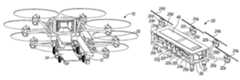
- FIG. 1is a perspective view of a vehicle according to an embodiment of the invention
- FIGS. 2A , 2 B, 2 C, 2 D, 2 E, 2 F, and 2 Gare front perspective, top, bottom, side, front, back, and back perspective views, respectively, of an air vehicle according to an embodiment of the invention
- FIGS. 2H-2Iare close-up views of a landing support according to an embodiment of the invention.
- FIGS. 3A through 3Care top, top (in cross-section), and perspective views of the air vehicle from FIG. 2A showing various positions of the engines and propellers and support arms;
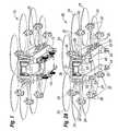
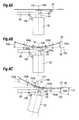
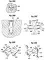
- FIGS. 4A and 4Bare side views, respectively, of a propeller support arm assembly according to an embodiment of the invention.
- FIG. 4Cis a close-up top view, in cross section, of a portion of the propeller support arm assembly of FIG. 4A ;
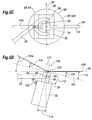
- FIGS. 5A and 5Bare top and back views respectively of an engine and propeller assembly and support in vertical lift configuration according to an embodiment of the invention
- FIGS. 5C and 5Dare top and back views of the engine and propeller assembly and support of FIG. 5A in forward flight configuration
- FIGS. 6A-6Care back views of an engine and propeller assembly and support according to a further embodiment of the invention.
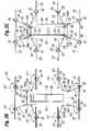
- FIGS. 7A and 7Bare top views of a flight vehicle according to an embodiment of the invention.
- FIG. 8is a perspective view, in partial cross section, of a fuel tank assembly of an air vehicle according to an embodiment of the invention.
- FIG. 9Ais a perspective view of an air vehicle carrying an external payload
- FIG. 9Bis a side view of the external payload from FIG. 9A ;
- FIG. 10Ais a perspective view of an air vehicle carrying a ground vehicle
- FIG. 10Bis a perspective view of the ground vehicle from FIG. 10A ;
- FIGS. 10C and 10Dare front and perspective views of a vehicle having a ground vehicle and air vehicle and configured to be driven on the ground;
- FIGS. 11A-11Care perspective views of an air vehicle lowering a ground vehicle via cables
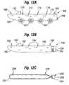
- FIGS. 12A-12Care side views of vehicles configured for carrying by an air vehicle according to an embodiment of the invention.
- FIG. 13Ais a perspective view of an air vehicle with aerial elevator preparing to lift a payload according to an embodiment of the invention
- FIG. 13Bis a perspective view of the air vehicle with aerial elevator of FIG. 12A lifting the payload;
- FIG. 13Cis a perspective view of the air vehicle with aerial elevator of FIG. 12A with the payload lifted and secured to the exterior of the air vehicle;
- FIG. 13Dis a perspective view of an air vehicle with aerial elevator with a payload lifted and secured within the interior of the air vehicle;
- FIGS. 14A-14Care perspective views of an air vehicle tethered with a ground vehicle according to an embodiment of the invention.
- FIG. 15depicts a perspective view of an air vehicle with graspers according to an embodiment of the invention.
- FIGS. 16A and 16Bdepict perspective and side view, respectively, of air vehicles with armor and gun mounting arrangements according to an embodiment of the invention
- FIG. 16Cdepicts a side view of an air vehicle with gun mount according to a further embodiment of the invention.
- FIGS. 17A and 17Bare side and perspective views, respectively, of a ground vehicle loading a cargo module into an air vehicle according to an embodiment of the invention
- FIG. 17Cis a side view of the cargo module and ground vehicle of FIGS. 17A-17B secured to the air vehicle;
- FIG. 18Ais a perspective view of an air vehicle comprising flight components releasably attached to a shipping container according to an embodiment of the invention
- FIG. 18Bis a close-up view of a flight component of FIG. 18A ;
- FIG. 18Cis a perspective view of an air vehicle comprising flight components releasably attached to a shipping container according to a further embodiment of the invention.
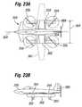
- FIGS. 19A and 19Bare perspective and side views respectively of a flight vehicle in a forward flight configuration according to an embodiment of the invention.
- FIGS. 20A and 20Bare perspective and (partial) top views, respectively, of an attachment frame according to an embodiment of the invention.
- FIGS. 20C and 20Dare close-up views of an attachment frame being secured to a ground vehicle according to an embodiment of the invention.
- FIG. 20Eis a side view depicting an air drop of an air vehicle according to an embodiment of the invention.
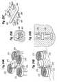
- FIGS. 21A and 21Bare perspective and side views, respectively, of an air vehicle according to an embodiment of the invention.
- FIGS. 22A and 22Bare top views of air vehicles according to embodiments of the invention.
- FIG. 22Cis a side view of the air vehicle of FIG. 22 b;
- FIGS. 23A and 23Bare top and side views, respectively, of an air vehicle according to an embodiment of the invention.
- FIGS. 24A and 24Bare perspective views of an air vehicle according to an embodiment of the invention.
- FIGS. 25A , 25 B, and 25 Care front, side, and perspective views, respectively, of an air vehicle according to an embodiment of the invention.
- FIGS. 26A-26Eare front, top (stored), top (deploued), perspective (vertical takeoff), and perspective (forward flight) views of various configurations of an air vehicle according to an embodiment of the invention.
- FIG. 1depicts a vehicle 10 according the invention.
- the vehicle 12includes a transport module 14 in the form of a ground vehicle 16 mated to an air vehicle 20 .
- FIGS. 2A-2Edepict an air vehicle 20 according to an embodiment of the invention, comprising a main airframe 22 having a forward axis 23 passing through its middle in back-to-front fashion.
- Eight (8) propellers 24extend from the airframe 22 on propeller supports 26 .
- Each propeller support 26has a proximal end 28 secured to the main airframe 22 , and a distal end 30 .
- each propeller 24is linked to and individually powered by a devoted engine 32 , with a linked propeller 24 and engine 32 forming an engine-propeller assembly 34 .
- One engine-propeller assembly 34is positioned at the distal end 30 of each propeller support 26 .
- each of the engines 32provides about 140 or more horsepower, with each engine 32 driving a propeller 24 having an overall length of about 7-9 feet.
- the propellers 24may be configured to be easily removed and replaced, either with identical propellers or with different types of propellers, such as propellers which are longer or shorter, etc.
- the propellers 24are spaced around the main airframe 22 , with four of the propellers 24 extending from the airframe front 36 and four of the propellers 24 extending from the airframe rear 38 .
- Four of the propellers 24extend from the airframe left side 40
- the other four propellers 24extend from the airframe right side 42 .
- the propellers 24 and propeller supports 26extend in pairs from the airframe corners 44 a , 44 b , 44 c , 44 d .
- Different propellers 24 of the air vehicle 20can rotate in different directions, depending on the particular application and including such variables as the spacing of the propellers, the total number of propellers on a particular air vehicle, and other characteristics of a particular air vehicle, including the engines and propellers thereof.
- the propellers 24 extending from the airframe left side 40have a rotational direction 47 left in a generally counterclockwise fashion when viewed from above, while the propellers 24 extending from the airframe right side 42 have a rotational direction 47 right in a generally clockwise fashion when viewed from above.
- each propeller 24With such rotations, the blades of each propeller 24 are in a forward motion with respect to the air vehicle 20 when they are closest to the airframe 22 , and are in a backward motion with respect to the air vehicle 20 when they are furthest away from the airframe 22 .
- adjacent propellersmay rotate in opposing directions, similar to the egg-beater style opposing rotation of the helicopter blades of a two-propeller Chinook helicopter.
- the propellers 24are positioned generally aligned in an air vehicle horizontal plane 46 adjacent the airframe top 48 , and are tilted slightly forward from the air vehicle horizontal plane 46 by a forward tilt angle 50 , such as a forward tilt angle of zero to 5 degrees, with 3 degrees being appropriate for some applications.
- the forward tilt angle 50 of each propeller 24can vary (including variations from propeller to propeller), depending on the particular embodiment.
- propellers 24are generally fixed at a forward tilting angle 50 of about zero to 5 degrees.
- the propellers 24can be selectively rotated in flight (using a mechanical tilting mechanism such as a hydraulic, electric, or other device or assembly) through various tilt angles, including from horizontal to forward by about 90 degrees or even backward by up to about 90 degrees (i.e., a forward tilt angle 50 of ⁇ 90 degrees).
- a mechanical tilting mechanismsuch as a hydraulic, electric, or other device or assembly
- some of the propellershave very small forward, or even zero, forward tilt angles, while other propellers are tilted forward at much greater angles.
- an air vehicle horizontal planeis defined as a plane passing through the air vehicle in a generally horizontal manner with respect to the air vehicle, i.e., horizontal when the air vehicle is on the ground and/or when in a level configuration (e.g., in purely vertical flight mode).
- the landing supports 52Extending from the bottom 49 of the main airframe 22 are landing supports 52 configured to support the weight of the air vehicle 20 when it is resting on the ground.
- the landing supports 52include wheels 54 to permit the air vehicle 20 to be rolled and/or driven on the ground.
- the wheels 54may be powered and/or steerable, or may be free moving, depending on the particular application.
- the air vehicle 20may include floats for landing on and/or cruising in a boat-like fashion on water, skis for landing on and/or cruising on snow and/or ice, or other assemblies for landing and/or traveling on various surfaces.
- FIGS. 2H-2Iare in their flight position, but are each configured to swing outward about an axis 56 to a landing position, whereby the landing supports 52 extend from the sides of the vehicle, as depicted in the close-up views of FIGS. 2H-2I .
- the landing supports 52have a length 55 , and in the particular embodiment depicted are configured to extend in length 55 from a shorter retracted (flight) configuration in FIG. 2H to a longer deployed (landing) configuration in FIG. 2I .
- the landing supports 52may have sufficient height 55 when deployed to permit a ground vehicle to be driven under the main airframe 22 .
- the landing supports 52may be extendable and/or retractable, and may be configured to telescope in length 55 and/or to swing or otherwise extend outward from the main airframe 22 .
- the landing supports 52may include hydraulic, electric, and/or other extending mechanisms to extend, retract, and/or otherwise reposition the landing supports 52 , and such extending mechanisms may have sufficient lifting capacity to lift the air vehicle 20 , when on the ground, from a relatively low height (such as may be desirable to directly load the air vehicle 20 , such as through the rear door 48 ), to a height sufficient for a ground vehicle to be driven thereunder.
- Landing supportscan also be secured to the engine/propeller supports and/or to the engine/propeller assemblies.
- engine/propeller assembliescould include wheels, floats, etc. extending beneath them to provide increased stability in situations where an engine/propeller assembly might contact the ground, such as where the air vehicle is landing on uneven terrain and/or water.
- Such landing supports on the engine/propeller assemblies and/or supportscould also facilitate movement of the engine/propeller assemblies and/or supports when detached from the air vehicle, such as where such assemblies are being replaced or repaired.
- a cockpit 37is in the front 36 of the air vehicle 20 , from which a pilot can control the air vehicle 20 in flight and on the ground.
- the cockpit 37may have a cover/windshield configured to swing outwardly open to act as a door through which the crew can access the vehicle.
- the air vehicle 20may include a rear door 58 , which in the particular embodiment depicted (in a closed configuration in FIG. 2F and an open configuration in FIG. 2G ) opens by lowering and forming a ramp for loading materials in the air vehicle 20 through the airframe rear 38 .
- the propellers 24are directly powered by engines 32 directly secured thereto by simple drive shafts.
- engines 32directly secured thereto by simple drive shafts.
- various engines and engine assembliescan be used with the invention.
- the enginescan be mounted at the end of supports along with propellers, as in the embodiment of FIG. 2A , or the engine or engines can be mounted elsewhere (such as in or on the main airframe) and connected to the propellers via a drive shaft assembly.
- the specific engine type and power to be useddepends on the particular application, including the air vehicle size, number and size of propellers, desired flight characteristics such as lift and speed, etc.
- the enginesare Meyer nutating, Hirth 2-cycle, or Thielert 4-cycle or similar engines, including engines that burn jet, diesel, heavy fuel, and/or gasoline and can each provide 110 to 150 horsepower.
- Such enginescan be linked to propellers having lengths of 7 feet to 21 feet.
- Other sizes and configurationare also within the scope of the invention, including very large vehicles with lifting capacities of 100,000 lbs using 4000 horsepower turbine engines driving 80 foot propellers or rotors.
- the propellerscould be directly powered by electric motors, with electricity provided by batteries and/or solar cells. Electricity could also be provided by a conventional engine that consumes fuel (e.g., gas, diesel, jet fuel, hydrogen, etc.) and acts as a generator to provide electricity to the electric motors and/or batteries in a so-called “hybrid” arrangement.
- fuele.g., gas, diesel, jet fuel, hydrogen, etc.
- these unpowered propellersmay begin to autorotate, particularly when the vehicle is in forward flight.
- Such autorotation of a propeller or propellerscould cause a corresponding turning of the corresponding electric motor(s), and this turning of the electric motor could be used to act as a generator, thereby generating electricity which could be fed into the batteries and/or into the other electric motors.
- an air vehicle 20has propellers 24 a - h positioned on supports 26 a - h .
- the propellers 24 a - d on the left side 40 of the airframe 22are depicted in the deployed (i.e., flight) configuration, wherein the supports 26 a - d are rotated away from the airframe 22 at angles 60 a - d therefrom.
- the propellers 24 e - h on the right side 42 of the airframe 22are depicted in their stored configuration, with the supports 26 e - h folded against the airframe 22 (so that the angles 60 e - h are generally equal to about zero) and the propellers 24 e - h (which are two-bladed propellers in the particular embodiment depicted) and engines 32 e - h aligned snugly against the airframe 22 and to each other.
- FIGS. 2A-2Bdepict supports secured to the corners of the airframe
- FIGS. 2A-2Bdepict supports secured to the corners of the airframe
- supportscould be secured to a more central portion of the airframe, including in the center of either side.
- Such support attachment locationscould facilitate repositioning of engine/propeller assemblies via variation of the associated angles by which the supports are rotated away from the airframe (such as angles 60 a - d from FIG. 3A ).
- FIG. 4Adepicting one such embodiment.
- the support 26has an arm 70 having a distal end 72 having a support 74 configured to hold an engine/propeller assembly 34 , and a proximal end 76 secured to a triangular truss assembly 78 .
- the triangular truss assembly 78includes an upper portion 80 secured to the main airframe 22 via an upper connection 82 near the airframe top 48 , and a lower portion 84 secured to the main airframe 22 via a lower connection 86 .
- the support 26 and/or engine 32 and/or propeller 24may be configured to be dropped from the air vehicle 20 in case of an emergency such as loss of engine power (such as due to mechanical failure) or fire on, damage to, or loss of an engine 32 and/or propeller 24 such as may be caused by enemy attack.
- the upper connection 82is configured with a breakaway mechanism, such as a small explosive configured to sever all or a portion of the upper connection 82
- the lower connection 86can comprise a ball joint or similar connection.
- the upper connection 82comprises a bracket 83 secured to a rod 85 that passes through a hole 87 in the upper portion 80 of the triangular truss 78 of the support 26 .
- severing the upper connection 82permits the entire support 26 (potentially with attached engine 32 and propeller 24 ) to fall away and outward via gravity and the rotational moment about the ball joint of the lower connection 86 , as depicted in FIG. 4B . If the propeller 24 is still generating lift sufficient to lift the support 26 and propeller/engine assembly 34 , the inner wall 89 of the bracket 83 will prevent the triangular truss upper portion 80 from being pushed inwardly into the airframe 22
- the propeller supportsmay be able to extend in length, e.g., in telescopic fashion, during vehicle set-up and/or during flight.
- the propeller supportscan and may be secured to various positions on the airframe, e.g., the center of a side, front, or back (instead of at the corners), etc.
- one or more of the propellers 24 of an air vehicle of an embodiment of the inventionmay be configured to tilt from one side to another with respect to the direction of flight 90 of the air vehicle 20 .
- 5A and 5Bdepict such a propeller 24 and engine 32 , with the propeller and engine assembly 34 and propeller support 16 in vertical lift configuration.
- the propeller 24rotates in a clockwise fashion when viewed from above to define a 360 degree rotation 88 , so that if this configuration is maintained when the vehicle shifts to forward motion an advancing propeller blade 24 a (i.e., for a clockwise rotation the left-hand portion 88 left of its rotation 88 with respect to the flight direction 90 , where the blade is advancing with respect to the flight direction 90 ) will create more lift than a retreating propeller blade 24 r (i.e., for a clockwise rotation a blade passing through the right-hand portion 88 right of its rotation 88 with respect to the flight direction 90 , where the blade is retreating with respect to the flight direction 90 ).
- the engine 32is held at the distal end 30 of the propeller support 26 by a generally U-shaped propeller/engine support 92 having a rod 94 passing between the ends 96 thereof.
- the rod 92defines a rotational axis 98 about which the entire propeller/engine assembly 34 can rotate.
- the rotational axis 98 for the propeller/engine assembly 34is generally aligned with the flight direction 90 of the air vehicle, except for any forward or backward tilt (such as the propeller tilt angle 50 depicted in FIG. 2D ).
- a rotational controller in the form of a shock absorber 100extends from the engine 32 to the propeller support 26 , and serves to control and limit rotation of the propeller and engine assembly 34 about the rotational axis 98 .
- the rotational controllercould also be an active controller, such as a servo actuator that causes and/or prevents rotation of the propeller/engine assembly 34 subject to commands from a control system.
- the propeller 24is positioned above the engine 32 , and is directly connected to the engine 32 via a drive shaft 102 .
- the particular propeller 24has blades each of which are inclined slightly upward at an angle 104 from a plane 106 perpendicular to the drive shaft 102 .
- the drive shaft 102(which aligns with to the rotational axis 108 of the propeller 24 ) will typically be a purely vertical axis 110 (i.e., 90 degrees from the horizontal) when viewed from behind the direction of movement as in FIG. 5B , so that the plane 106 will generally be parallel to the air vehicle plane 46 .
- FIGS. 5C and 5Ddepict a support 26 and propeller/engine assembly 34 when the air vehicle is in forward flight.
- the uneven lifting forces on the propeller 24have created a rotational moment 112 (clockwise when viewed from the rear as in FIG. 5D ) about the propeller/engine assembly 34 , and the entire propeller/engine assembly 34 has slightly rotated by an assembly rotation angle 114 , with the assembly rotation angle 114 controlled and/or limited by a rotation controller such as the shock absorber 100 .
- the assembly rotation angle 114causes the propeller 24 to tilt slightly toward the right so that the propeller rotational axis 108 is tilted to the right of the vertical axis 110 .
- an advancing propeller blade 24 a in the forward sweep of its rotation( 88 left in FIG. 5C ) is at a relatively large effective angle 104 a from the air vehicle plane 46
- a retreating propeller blade 24 r in the rearward portion of the rotation( 88 right in FIG. 5C ) is at a very small effective angle 104 b , and may even be generally parallel to, the air vehicle plane 46 .
- the change in anglescreates a reduced effective lift area under advancing blade 24 a (i.e., on the left side when viewed in FIG. 5D ) but increased effective lift area under the retreating blade 24 r (i.e., on the right side in FIG. 5D ).
- FIGS. 5A-5Ddepicted a propeller 24 having blades with a fixed angle 104 relative to a plane 106 perpendicular to the drive shaft 102 .
- a propeller 24 that is flat when not providing liftmay define a curved shape when rotating and subjected to the lifting forces created thereby, as in FIG. 6B .
- Such a propeller 24will define varying angles 104 a , 104 b , 104 c from the plane 106 along its length, with an angle 104 a of about zero at portions of the propeller 24 adjacent the drive shaft 102 , but the angles 104 b , 104 c will steadily increase for portions of the blade 24 that are further from the drive shaft 102 .
- the angles 104 a , 104 b , 104 cwill typically be equal from the left side to the right side, as depicted in FIG. 6C .
- a rotational propeller/engine assembly supportsuch as that of FIGS.
- a curved propellerwill also achieve a generally balanced lift pattern in response to rotation of the propeller and engine assembly, as depicted in FIG. 6C .
- the resultis increased angles between the advancing blade 24 a and the air vehicle plane 46 , and decreased angles between the retreating blade 24 r and the air vehicle plane.
- the change in anglescreates a reduced effective lift area under advancing blade 24 a (i.e., on the left side when viewed in FIG. 6C ) but increased effective lift area under the retreating blade 24 r (i.e., on the right side).
- the reduction/increase in effective lift areacounters the increased/decreased lift caused by the advancing vs. retreating blade, so that the resulting lift pattern is generally equal throughout the blade sweep.
- the forward tilt angle (i.e., angle 50 from FIG. 2D ) and/or sideways angle (i.e., angle 114 from FIGS. 5D and 6C ) of a propeller 24can be varied using various techniques.
- an electric motor, hydraulic system, or other mechanismcould be used to tilt the engine/propeller assembly 34 (or just the propeller 24 itself), and/or all or a portion of the propeller support 26 .
- one or more connections by which a propeller support is secured to the airframecould be moved (i.e., the upper connection moved forward with respect to the airframe, and/or the lower connection moved backward with respect to the airframe) in order to tilt the propeller support and thereby tilt the propeller forward.
- connection movementscould tilt the propeller backward.
- an upper connectioncould be moved outward while the lower connection could be moved inward, thereby tilting the propeller support outward and thereby tilting the propeller outward. Reversing these movements could tilt the propeller inward.
- connection movementsmay also be used, either alone or in combination with other devices and/or configuration changes, to raise or lower supports, engines, and/or propellers with respect to the airframe.
- the propeller supportcould be secured to the airframe via a bracket, and the bracket could be rotated or otherwise moved (via motors, hydraulics, etc.) to reposition the propeller support and thereby reposition the propeller angle(s) or height, etc.
- propellersWhile two-bladed propellers have been depicted herein, the invention is not limited so such propellers. While two-bladed propellers may have advantages for stowing, manufacture, and/or travel, propellers with any number of blades can be used with the invention.
- the propellersmay be configured to store in different ways. For example, they may fold along one or more sides, front, back, top, or bottom of the vehicle, or be configured for partial or complete disconnect/reconnect from the vehicle for storage/shipping and/or propeller exchange. Propellers may be able to rotate from their deployed (flight) position to the stowed position, and vice-versa, either manually or via electric, hydraulic, mechanical, etc. methods.
- the support angles 60 a - h of the various propeller supports 26 a - hcan vary according to the particular application, including the generally air vehicle configuration, number of propellers, load capabilities, etc.
- the supports 26 a , 26 d , 26 e , and 26 h holding the front-most and rear-most engine/propeller assemblies 34 a , 34 d , 34 e , 34 hextend at angles 60 a , 60 d , 60 e , and 60 h of about 150 to 170 degrees
- the supports 26 c - f supporting the central propellers 24 c - fextend at somewhat smaller angles 60 b - c , 60 f - g of about 60 to 80 degrees.
- the supports 26 a - hmay be configured so that the support angles 60 a - h can be varied in flight, so that one or more of the supports 26 a - h can be angled outward or inward to reposition the corresponding engine/propeller assemblies 34 a - h to compensate for center of gravity changes, changes in thrust from various engines, loss of one or more engines, and/or for other reasons necessary to enhance the flight capabilities of the air vehicle 20 .
- one or more supports 26 a - hcan change their support angles 60 a - h in flight to compensate for different weight balances and centers of gravity, and/or to compensate for loss of one or more engine/propeller assemblies 34 a - h (including loss of use thereof). For example, FIG.
- FIG. 7Bdepicts the flight vehicle of FIG. 7A having lost two engine/propeller assemblies 34 c - d , but with other engine/propeller assemblies 34 a - b , 34 g - h repositioned to compensate for the propeller losses.
- the supports 26 a - b , 26 g - hhave been changed in their angles 60 a - b , 60 g - h to reposition engine/propeller assemblies 34 a - b , 34 g - h , with angles 60 a , 60 b being decreased and angles 60 g , 60 h being increased.
- the new propeller positionscompensate for the propeller loss, and further compensation can be provided by adjusting thrust from different propellers, adjusting the center of gravity via methods such as moving fuel from tanks from side-to-side and/or front-to back and/or vice-versa, etc.
- the air vehicle 20includes an active flight control system that constantly monitors the flight characteristics, including center of gravity, thrust from each propeller 24 a - h , power from each engine 32 a - h , air vehicle speed and attitude, etc., and automatically adjusts one or more of the propeller forward tilt angles 50 a - h , propeller assembly side-to-side angles 114 , and/or support angles 60 a - 60 h in order to reposition one or more of the propellers 24 a - h to maximize the flight performance, including such factors as lift, fuel efficiency, etc.
- active flight control systemthat constantly monitors the flight characteristics, including center of gravity, thrust from each propeller 24 a - h , power from each engine 32 a - h , air vehicle speed and attitude, etc., and automatically adjusts one or more of the propeller forward tilt angles 50 a - h , propeller assembly side-to-side angles 114 , and/or support angles 60 a - 60 h in order to
- the flight control systemmay also adjust propeller position, engine power (and hence propeller thrust), and center of gravity (via fuel movement, etc.) to compensate for various factors such as loss of one or more engines and/or propellers.
- the active flight control systemcan adjust the RPMs of each engine via throttle controls in order to balance the thrust from the engines with respect to the center of gravity of the vehicle. If the center of gravity is off-center, the air vehicle can compensate by adjusting engine power (thereby adjusting propeller thrust) and also by transferring fuel between different fuel tanks.
- FIG. 8depicts a fuel tank assembly 120 of an air vehicle 20 , with multiple fuel tanks 122 positioned in the vehicle.
- the fuel tanks 122are generally vertical in shape in order to minimize sloshing of the contents, which could impact center of gravity and otherwise complicate flight characteristics of the air vehicle.
- Tank-to-tank fuel transfer lines 124permit rapid and effective fuel between tanks 122 in order to even out the amount of fuel in each tank, balance the center-of-gravity, and/or for other purposes.
- Fuel transfer pumps 126control the movement of fuel between fuel tanks 122 .
- Fuel lines 128lead from the fuel tanks 122 through the supports 26 to the engines 32 . Fuel can be fed to the engines via pumps and/or other methods (such as gravity, etc.), depending on the particular embodiment.
- the air vehicle 20may be configured to have fuel drop tanks 130 secured thereto.
- fuel drop tanks 130are positioned on either side of the vehicle, generally toward the center of each side and low on the vehicle.
- the fuel drop tanks 130provide extra range to the air vehicle 20 .
- the drop tanks 130are attached via connectors, with drop tank fuel lines configured to transfer fuel from the drop tanks 134 to the onboard fuel tanks 122 and/or directly to the engines 32 . Pumps may be used to control such fuel transfer.
- the drop tanks 130may be configured for easy connection and disconnection from the air vehicle 20 .
- quick-connect/disconnect assembliesmay be used for quick connection and disconnection of the drop tank fuel lines, and such assemblies may also be configured to be self-sealing.
- the drop tank connectors 132may be configured for rapid disconnect during normal operations (e.g., loading and unloading, etc.) and/or for dropping (e.g., via explosives or other rapid disconnect devices) of the drop tanks 130 , such as where a drop tank 130 is empty of fuel and it is desirable to drop the drop tank 130 .
- the drop tanks 130can be dropped in flight or on the ground.
- Air vehicles according to the inventionmay also include fuel lines and connections to transfer fuel between a transport module, such as a ground vehicle, to the air vehicle, or vice versa.
- the air vehiclewill typically include one or more gas fuel openings through which fuel can be added in the traditional manner (e.g., from a traditional gas pump such as found at gas stations).
- the air vehiclemay be configured to automatically transfer fuel to and/or from a transport module when available.
- the air vehiclemay also include in-air refueling devices to permit the air vehicle to be refueled in flight by an airborne tanker airplane or other airborne refueling platform.
- FIG. 9Adepicts an embodiment of a vehicle 10 , where an air vehicle 20 is carrying a transport module 12 in the form of a cargo module 140 .
- the cargo module 140depicted alone in FIG. 9B , is configured be secured to the underside 49 of the air vehicle 20 .
- the cargo module 140includes one or more doors 142 through which cargo can be loaded, and includes connectors 144 configured to be mated to corresponding connectors on the air vehicle 20 .
- a vehicle 10may include a transport module 12 in the form of a ground vehicle 14 , such as that depicted in FIGS. 10A-10B .
- the ground vehicle 14is configured to drive on land via wheels 150 .
- the ground vehicle 14includes connectors 152 configured to be mated to corresponding connectors on the air vehicle 20 .
- the particular ground vehicle 14 depictedincludes a rear cargo area 154 and a front cockpit 156 from which a driver can control the vehicle, which may be accomplished using traditional ground vehicle controls (e.g., steering wheel, gas pedal, brake, etc.).
- a ground vehicle 14 or other transport modulemay include skis, skids, tank-like tracks, and/or other drive devices, depending on the particular application (including the terrain over which the ground vehicle is anticipated to operate).
- the vehicle or other transport modulemay include floats for landing on and/or cruising in a boat-like fashion on water.
- the vehicle 10 when on the groundcan be driven using the ground vehicle 14 , with the air vehicle 20 secured to the top thereof as depicted in FIGS. 10C-10D .
- the engine/propeller assemblies 34 and struts 26can be retracted and folded against/inside the air vehicle 20 , and the air vehicle supports 52 can be retracted (if not already retracted prior to landing) so that the wheels 150 of the ground vehicle 14 carry the entire weight of the vehicle 10 , including the weight of the air vehicle 20 and ground vehicle 14 .
- Controlling the driving of the entire vehicle 10 over the groundcan be accomplished via the ground vehicle cockpit 156 or from the air vehicle cockpit 36 , with controls in either cockpit 156 , 37 configured to control (through direct connections, wireless, etc.) the power to and steering of the ground vehicle wheels 150 .
- a transport module 12such as a ground vehicle 14 can deposited onto the ground or other surface by having the air vehicle 20 (with ground vehicle 14 attached) land on the ground or other surface and then release the ground vehicle 14 therefrom.
- the transport module 12can similarly be removed from the surface by securing the air vehicle 20 to the transport module 12 /ground vehicle 14 when on the ground, and then lifting off the combined vehicle 10 using the air vehicle 20 to directly lift the transport module 12 /ground vehicle 14 .
- a transport module 12 in the form of a ground vehicle 14is lowered onto the surface from an airborne air vehicle 20 using cables 158 (powered by winches or other reeling devices), so that the air vehicle 20 remains airborne at all times during landing of the ground vehicle 14 .
- the processcan be reversed to lift the ground vehicle 14 up to the airborne air vehicle 20 , with the cables 158 and winches used to lift the ground vehicle 14 .
- the cables 158are secured to the corners of the ground vehicle 14 in order to provide better balance when lifting and/or lowering the ground vehicle 14 .
- the cablescan also be used to guide the air vehicle 20 to a landing on top of a surface-based transport module 12 such as the ground vehicle 14 , wherein one or more of the cables can be winched in to draw the air vehicle 20 down onto the top of the ground vehicle 14 .
- a transport module 12may be an amphibious vehicle 160 configured for crossing land and water, as depicted in FIG. 12A .
- the amphibious vehicle 160includes a generally boat-like hull 162 and has sufficient buoyancy to float in water.
- a ground drive system in the form of multiple inflated wheels 164(which also provide buoyancy) is used to drive the amphibious vehicle when on land.
- a water drive system in the form of one or more propellers 166provides forward thrust when in water. Note that other types of ground and water drive systems are also within the scope of the invention, including skis, skids, tank-like tracks, water-jet propulsion, rudders, and/or other drive and/or steering devices.
- the amphibious vehicle 160includes connectors 168 configured to be mated to corresponding connectors on the air vehicle 20 .
- the amphibious vehicle 160can include controls, including a steering wheel 170 , as well as a windshield 172 and one or more seats 174 . All elements that extend above the top 176 of the amphibious vehicle 160 may be configured to fold down below the top in order for the amphibious vehicle 160 to be secured to the air vehicle 20 .
- FIG. 12Bdepicts a boat 180 configured for carrying by an air vehicle.
- the boat 180includes a hull 182 , propulsion system in the form of one or more propellers 184 , and a rudder 186 .
- propulsion systemin the form of one or more propellers 184
- rudder 186a boat 180 configured for carrying by an air vehicle.
- Connectors 188are configured to mate with connectors on the air vehicle.
- a windshield 190 , steering wheel 192 , and seats 194are configured to fold or otherwise drop below the boat top 196 to facilitate securing the boat 180 to an air vehicle.
- FIG. 12Cis a side view of a submersible 200 configured for carrying by an air vehicle.
- the submersible 200includes a hull 202 , propeller(s) 204 , and rudder 206 .
- Connectors 208are configured to mate with corresponding connectors on the air vehicle, and the submersible's connectors 208 may be configured to fold or otherwise retract into the hull after submersible deployment in order to reduce drag on the submersible 200 when submerged.
- a vehicle 10may include an aerial elevator 210 configured to lift a payload 212 to the in-flight air vehicle 20 .
- an aerial elevatorincludes a frame 214 secured at its corners 216 to lift lines 218 . Winches 220 or other hoisting devices are used to let out and/or pull in the lift lines 218 and thereby lower or raise the frame 214 .
- the frame 214may be a generally rigid structure, which may prevent unwanted movement of lift lines 218 that might occur of the lift lines 218 were unattached to any structure at their lower ends as they were lowered.
- the frame 214can include connectors configured to be secured to the payload 212 , such as by being mated to corresponding connectors on the payload 212 .
- the frame 214may also include connectors configured to be secured to the air vehicle 20 .
- FIG. 13Athe frame 214 is being lowered toward the payload 212 .
- the frame 214is then connected to the payload 212 and the frame 214 with attached payload 212 is lifted, as depicted in FIG. 13B , which can be accomplished by using the winches 220 to reel in the lines 218 .
- the frame 214can be secured to the air vehicle 20 , thereby securing the payload 212 to the air vehicle 20 , as depicted in FIG. 13C , with the payload 212 secured to the underside 49 of the air vehicle 20 .
- the payload 212could be lifted up entirely (or partially) within the air vehicle 20 itself, as depicted in FIG. 13D .
- FIG. 14Adepicts an air vehicle 20 in flight but tethered to a ground vehicle 14 according to an embodiment of the invention.
- the tether line 230has a lower portion 232 secured to a hook 234 or other connection on a landing pad 236 on the ground vehicle 14 .
- the landing pad 236includes extendable portions 238 that project from the sides of the ground vehicle 14 .
- the tether line 230extends from a winch or other reel device configured to pull in and let out the tether line 230 .
- the tether line 230can be carried on the air vehicle 20 , and then the distal portion 232 thereof dropped to the ground vehicle 14 to be secured to the hook 234 .
- the winchcan then be used to pull the air vehicle 20 down onto the landing pad 236 , with the end result being the air vehicle 20 is on the landing pad 236 and secured thereto via the tether line 230 , as depicted in FIG. 14B .
- the engine/propeller assemblies 34can be folded into the sides of the air vehicle 20 , and the ground vehicle 14 can drive with the air vehicle 20 secured to the top thereof.
- the tether 230can be used to assist in guiding the air vehicle 20 to land on the ground vehicle 14 (or on other desired locations, such as on a ship, narrow ledge, etc.).
- the tether 230could also be used to lift the ground vehicle 14 or other module, either by: winching the ground vehicle 14 via the tether 230 and winch/reel up to an airborne air vehicle 20 ; or securing the tether 230 to the ground vehicle 14 and using the air vehicle propellers 24 to lift the air vehicle 20 and ground vehicle 14 , either by first landing the air vehicle 20 and securing it tightly via the tether 230 to the ground vehicle 14 (so that the ground vehicle 14 is held tightly to the air vehicle 20 ), or without landing the air vehicle 20 on the ground vehicle 14 so that the ground vehicle 14 will hang some distance below the air vehicle 20 by a section of the tether line 230 .
- FIG. 15depicts an air vehicle 20 with graspers 240 extending from the airframe 22 .
- the graspers 240include arms 242 with hands 244 at the ends thereof.
- the graspers 240can be used to grasp and/or release objects, including transport modules, and can be controlled from the cockpit 37 , via remote control, etc.
- FIGS. 16A and 16Bshow an air vehicle 20 having armor 248 secured to the sides and bottom thereof.
- Guns 250are also provided to extend from the front and sides of the air vehicle 20 .
- Two turret-style guns 252are secured to the air vehicle bottom 49 , while an extendable gun 254 and extendable rocket launcher 256 are positioned on the top 48 of the air vehicle 20 .
- the armscan be controlled from the cockpit 37 or as otherwise desired for a particular application.
- FIG. 16Cdepicts a further embodiment of an air vehicle 20 , with an extendable gun turret-style gun 252 secured to an elongate arm 251 .
- the elongate arm 251is secured to the airframe 22 via a pivot 253 secured to a base form 255 that can rotate about an axis 257 on the top 48 of the airframe 22 adjacent the front 36 thereof.
- the turret-style gun 252can rotate about a first axis 259 , and also swing up or down for stowing via a hinge 249 that secures the turret-style gun 252 to the elongate arm 251 . As depicted in FIG.
- the turret-style gun 252can be positioned above the airframe 22 , then rotated over the airframe front 36 to a position below the airframe 22 , and moved to a stowed configuration along the top 48 of the airframe 22
- FIGS. 17A-17Cdepict an air vehicle 20 having a rear cargo area 260 that can be open at the air vehicle bottom 49 and at the air vehicle back 38 so that a cargo module 262 can be delivered therein by driving a ground vehicle 14 directly into position beneath the air vehicle 20 .
- the cargo module 262is positioned on top of the ground vehicle 14 , and the ground vehicle 14 is driven toward the air vehicle 20 by approaching the air vehicle 20 from the back 38 .
- the ground vehicle 14is driven underneath the air vehicle 20 until the cargo module 262 is positioned inside the rear cargo area 260 of the air vehicle 20 .
- the cargo module 262can be secured directly into the rear cargo area 260 and the ground vehicle 14 can be driven away (or simply left behind when the air vehicle 20 takes off), or the ground vehicle 14 can be secured to the air vehicle 20 so that the ground vehicle 14 is delivered to the deployment site along with the cargo module 262 .
- FIG. 18Adepicts an air vehicle 20 including flight components 270 releasably attached to a shipping container 272 at the corners 274 thereof.
- the shipping container 272can be a standard shipping container, and the flight components 270 include a base frame 276 having connectors configured to secure to standard connectors of the shipping container 272 .
- Each flight component 270comprises two engine/propeller assemblies 278 secured to two supports 280 , and also includes one or more fuel tanks 282 .
- a flight control system 284is also secured to the shipping container 280 , and communicates with the flight components via wires 286 and/or wireless connections.
- the flight control system 284can control the flight by adjusting engine RPMs/propeller thrust, repositioning propellers/supports at different angles, and/or angling propellers side-to-side and/or front-to-back.
- An individual flight component 270is depicted by itself in FIG. 18B . Note that a flight control system could be positioned on or in one or more of the individual flight components, with different flight control systems from different flight components communicating (vie wires or wireless) to coordinate control, so that the different flight control systems effectively act as a single flight control system that controls the flight of the entire air vehicle.
- FIG. 18Cis another embodiment of an air vehicle 20 that can act as a shipping container transport system, but where each flight component 270 comprises a base frame 276 and four engine/propeller assemblies 278 as well as a flight control system 284 and a cockpit 288 in which a pilot can sit to control the flight component 270 and/or air vehicle 20 (when the flight component is attached thereto).
- Each flight component 270can be flown by itself so that it can land and take off from a shipping container 272 and other positions. With two flight components 270 secured to a shipping container 272 (which in the particular embodiment of FIG.
- 18Cinvolves slipping a flight component base frame 276 over an end of the container 272 ), the flight control systems 284 of each flight component communicate with each other to coordinate the actions of each flight component 270 and its associated engine/propeller assemblies 278 to lift and transport the shipping container 272 to a desired location.
- Individual flight components for moving a shipping containercould include any number of propellers, engines, engine/propeller assemblies, flight control systems, etc. Flight components could be configured so that a single flight component could transport a shipping container without assistance from other flight components, and/or multiple flight components could be secured to a container for transport thereof.
- FIGS. 19A and 19Bdepict an air vehicle 20 (similar to that depicted in FIG.
- the front-most propeller set 24 a , 24 e , front central propeller set 24 b , 24 f , and rear-most propeller set 24 d , 24 hare each tilted slightly forward by an angle 114 and at generally the same heights with respect to the airframe 22 .
- the rear central propeller set 24 c , 24 ghas been moved substantially, so that the propellers 24 c , 24 g are at forward tilt angles 114 c , 114 g of about 90 degrees.
- the associated propeller/engine assemblies 34 c , 34 ghave been lowered with respect to the airframe 22 , which was achieved by lowering the supports 26 c , 26 g and also by rotating the propeller/engine assemblies 34 a , 34 g forward.
- additional propellerssuch as the front central propeller set 24 b , 24 f , could also be rotated forward and/or lowered to achieve even greater speeds.
- powercould be discontinued the front-most and rear-most propellers during forward flight, and these propellers could be allowed to autorotate in order to generate sufficient lift to maintain the vehicle at a desired altitude.
- Power to the other (i.e., vertical lift) propellerscould be reduced or even eliminated, with the forward-facing propellers 24 c , 24 g providing most of the power for forward flight and the other propellers 24 a , 24 b , 24 d , 24 e , 24 f , 24 h providing lift either via direct power or autorotation.
- propellerscould be repositioned up and down (or in and out), including above and/or below the airframe, to achieve improved aerodynamic performance.
- propellers to which power has been eliminatedmay be secured in a fixed position (such as a position generally parallel to the direction of forward flight in order to minimize drag), or may be permitted to autorotate (in which case they will typically generate some lift).
- a more aerodynamically efficient shellcould be used for and/or with the airframe to give improved performance.
- FIGS. 20A and 20Bdepict a frame 300 configured for attachment to a transport module such as a ground vehicle 14 .
- the frame 300which could be incorporated into a bottom structure of an airframe, includes a main U-shaped body 302 and a back portion 304 , with the back portion 304 configured to be swung away from the main U-shaped body 302 for direct access across the resulting back opening 306 .
- the frame 300includes connectors 308 adjacent the frame corners and mid-portion in the embodiment of FIGS. 20A and 20B .
- the connectors 308are depicted in close-up in FIGS. 20C (engaging) and 20 D (locked), and configured to mate with corresponding connectors 152 of the ground vehicle 14 .
- each frame connector 308has a recess 310 configured to receive a ground vehicle connector 152 .
- a locking member 312slides across the recess 310 and engages the ground vehicle connector 152 to secure the ground vehicle 14 to the frame 300 , as depicted in FIG. 20D .
- FIG. 20Edepicts a cargo plane 320 delivering an air vehicle 20 using an air drop approach.
- the air vehicle 20 ais depicted in various states of deployment as 20 a , 20 b , 20 c , 20 dm 20 e , and 20 f .
- the air vehicle 20 ais depicted just after having been dropped, with a parachute 322 a beginning to deploy.
- Air vehicle 20 bhas parachute 322 b in a further state of deployment.
- Parachute 322 chas fully stabilized air vehicle 20 c , which is in the process of deploying its engine/rotor assemblies 34 .
- Air vehicle 20 dis free of its parachute and is in flight via power to the rotors 24 .
- FIGS. 21A and 21Bdepict a heavy lift version of an air vehicle 20 , having separate decks inside configured to receive equipment and personnel.
- FIGS. 22A-22Cdepict a further embodiment of an invention, wherein propeller or ducted fan systems operate and hold an aircraft 340 in stable flight for vertical takeoff and landing and other maneuvering.
- the propellers or ducted fans 341are positioned generally equally about the center of gravity 342 , and are covered by doors which can open to provide vertical thrust, and remain closed during horizontal flight.
- the aircrafthas a front 343 .
- a rear directed engine(or ducting to direct propeller/ducted fans rearward) propels the aircraft in horizontal flight.
- FIGS. 23A and 23Bdepict a further embodiment of an invention, wherein an air vehicle 350 is configured to drive on the ground in a folded configuration (depicted in FIG. 23A ) via wheels 352 extending below to provide steering and/or power.
- the wheelsmay be powered from engines driving one or more of the propellers 356 , 360 .
- the air vehicle 350has a folded width 354 that permits it to drive down city streets.
- Four propellers 356are positioned on outward pontoons 358 , and are configured to provide vertical thrust for VTOL and/or STOL operations.
- a rear propeller 360provides forward thrust for horizontal flight and/or driving on the ground.
- the wings 362can fold out for flight or fold in for storage and/or ground travel.
- the propellers 356When in vertical flight, power to the propellers 356 can be reduced and/or eliminated, and/or the propellers can be locked in a position generally parallel to the direction of travel (which would typically be parallel to the forward axis 364 of the aircraft).
- the engines powering the vertical takeoff propellerscould be electric, with batteries in the pontoons 358 , and the other propeller(s) 360 could be powered by a more traditional fuel-driven engine that drives the propeller(s) 360 and also charges the batteries that provide electricity to drive the vertical takeoff propellers.
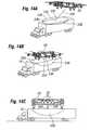
- FIGS. 24A and 24Bdepict an air vehicle 370 having a flight configuration ( FIG. 24A ) and ground configuration ( FIG. 24B ).
- the air vehicle 370has an upper set of propellers (or ducted fans) 372 configured to rotate to be positioned over the lower set of propellers (or ducted fans) 374 when in the ground configuration.
- the air vehicle 370can travel down highways and possibly even hover for short hops.
- a separate enginecan provide power to the ground wheels 376 or use one of the air vehicle motors.
- This vehiclecan be ducted fan or propeller driven, and may have a similar vertical takeoff stability system as other flight vehicles described herein.
- the passengers and driverssit in the middle section 378 .
- the two upper propellers 372can rotate from the ground configuration by about 90 degrees so the upper propellers 372 extend out from the sides of the air vehicle 370 , thus putting the air vehicle 370 in the flight configuration.
- FIGS. 25A-25Cdepict an embodiment of a flight vehicle 380 that can be launched from a torpedo or missile launch tube 382 as well as being ground and air launched.
- FIGS. 25A-25Bdepict the flight vehicle 380 stowed in a folded configuration (with wings and tail assembly folded up) within a missile launch tube 382
- FIG. 25Cdepicts the flight vehicle 380 unfolded and in flight.
- the air vehicle 380can fly with a forward flight propeller 384 for forward flight and vertical flight propellers 386 for vertical flight.
- the flight vehicle 380can be configured to be very portable and to fit in a standard Ohio class missile tube, with a stored width of 7 feet.
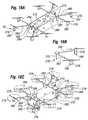
- FIGS. 26A-26Edepict another flight vehicle 400 , with a rotatable wing 402 that rotates on a pivot point 404 defining a generally vertical axis extending from the air vehicle fuselage 406 .
- Propellers 408are secured to the wing 402 via supports 410 , with the supports 410 rotatably secured to the wingtip and capable of rotating about an axis 412 passing generally wingtip-to-wingtip along the wing 402 .
- the entire flight vehicle 400can be folded up into a compact storage configuration, possibly sized and configured to fit within a launch tube 401 as depicted in FIGS. 26A-26B .
- the propeller supports 410are configured to fold along several hinges 414 for storage, as depicted in FIG.
- the propellerscan be positioned in horizontal configuration (i.e., with essentially no forward/backward, and/or side-to-side tilt), as depicted in FIG. 26E .
- the propellers 408can be rotated forward (by rotating the supports 410 about the axis 412 ) to provide forward thrust, as depicted in FIG. 26F .
- a dedicated forward thrust propeller 416may be provided.
- propellershave been discussed herein, rotors could be used in some versions of such air vehicles, such as where the air vehicles are very large and the associated propellers (rotors) have long lengths.
Landscapes
- Engineering & Computer Science (AREA)
- Aviation & Aerospace Engineering (AREA)
- Mechanical Engineering (AREA)
- Remote Sensing (AREA)
- Chemical & Material Sciences (AREA)
- Combustion & Propulsion (AREA)
- Transportation (AREA)
- Toys (AREA)
- Steering-Linkage Mechanisms And Four-Wheel Steering (AREA)
- Vehicle Body Suspensions (AREA)
Abstract
Description
Claims (19)
Priority Applications (3)
| Application Number | Priority Date | Filing Date | Title |
|---|---|---|---|
| US12/070,669US8453962B2 (en) | 2007-02-16 | 2008-02-19 | Modular flying vehicle |
| US13/907,975US9108728B2 (en) | 2007-02-16 | 2013-06-03 | Modular flying vehicle |
| US14/828,425US10526083B2 (en) | 2007-02-16 | 2015-08-17 | Modular flight vehicle |
Applications Claiming Priority (2)
| Application Number | Priority Date | Filing Date | Title |
|---|---|---|---|
| US90180907P | 2007-02-16 | 2007-02-16 | |
| US12/070,669US8453962B2 (en) | 2007-02-16 | 2008-02-19 | Modular flying vehicle |
Related Child Applications (1)
| Application Number | Title | Priority Date | Filing Date |
|---|---|---|---|
| US13/907,975DivisionUS9108728B2 (en) | 2007-02-16 | 2013-06-03 | Modular flying vehicle |
Publications (2)
| Publication Number | Publication Date |
|---|---|
| US20090008499A1 US20090008499A1 (en) | 2009-01-08 |
| US8453962B2true US8453962B2 (en) | 2013-06-04 |
Family
ID=40075709
Family Applications (3)
| Application Number | Title | Priority Date | Filing Date |
|---|---|---|---|
| US12/070,669Expired - Fee RelatedUS8453962B2 (en) | 2007-02-16 | 2008-02-19 | Modular flying vehicle |
| US13/907,975Expired - Fee RelatedUS9108728B2 (en) | 2007-02-16 | 2013-06-03 | Modular flying vehicle |
| US14/828,425ActiveUS10526083B2 (en) | 2007-02-16 | 2015-08-17 | Modular flight vehicle |
Family Applications After (2)
| Application Number | Title | Priority Date | Filing Date |
|---|---|---|---|
| US13/907,975Expired - Fee RelatedUS9108728B2 (en) | 2007-02-16 | 2013-06-03 | Modular flying vehicle |
| US14/828,425ActiveUS10526083B2 (en) | 2007-02-16 | 2015-08-17 | Modular flight vehicle |
Country Status (4)
| Country | Link |
|---|---|
| US (3) | US8453962B2 (en) |
| EP (1) | EP2121439B1 (en) |
| IL (3) | IL200421A (en) |
| WO (1) | WO2008147484A2 (en) |
Cited By (84)
| Publication number | Priority date | Publication date | Assignee | Title |
|---|---|---|---|---|
| US20130068876A1 (en)* | 2011-09-16 | 2013-03-21 | Bogdan Radu | Flying Vehicle |
| US20130140404A1 (en)* | 2011-12-05 | 2013-06-06 | Aurora Flight Sciences Corporation | System and method for improving transition lift-fan performance |
| US20130147204A1 (en)* | 2010-05-19 | 2013-06-13 | Eurocopter Deutschland Gmbh | Hybrid Drive And Energy System For Aircraft |
| US20130313359A1 (en)* | 2009-12-12 | 2013-11-28 | Heliplane, Llc | Aerovehicle system including plurality of autogyro assemblies |
| US20140061363A1 (en)* | 2009-05-22 | 2014-03-06 | Heliplane, Llc | Towable aerovehicle system with automated tow line release |
| US20140175214A1 (en)* | 2012-12-20 | 2014-06-26 | Gert Magnus Lundgren | Vtol_twin_propeller_attitude_control_air_vehicle |
| US20140217230A1 (en)* | 2013-02-05 | 2014-08-07 | Biosphere Aerospace, Llc | Drone cargo helicopter |
| US20140263823A1 (en)* | 2013-01-10 | 2014-09-18 | SZ DJI Technology Co., Ltd | Transformable aerial vehicle |
| US8870114B2 (en) | 2010-05-19 | 2014-10-28 | Eads Deutschland Gmbh | Hybrid drive for helicopters |
| US20150014475A1 (en)* | 2013-05-03 | 2015-01-15 | Aerovironment, Inc. | Vertical Takeoff and Landing (VTOL) Air Vehicle |
| US9004395B2 (en) | 2010-05-19 | 2015-04-14 | Eads Deutschland Gmbh | Drive system for helicopters |
| DE102013113452A1 (en)* | 2013-12-04 | 2015-06-11 | Telejet Kommunikations Gmbh | Warehouse with aircraft |
| US20150225071A1 (en)* | 2014-02-10 | 2015-08-13 | Northrop Grumman Systems Corporation | Tilt Wing Aerial Vehicle |
| US20150266570A1 (en)* | 2014-01-22 | 2015-09-24 | David Metreveli | Vertical Take-off and Landing Aerial Rescue and Firefighting Platform |
| US20150314865A1 (en)* | 2012-12-10 | 2015-11-05 | Gérome BERMOND | Convertible aircraft provided with two ducted rotors at the wing tips and with a horizontal fan in the fuselage |
| KR101566341B1 (en) | 2015-06-01 | 2015-11-05 | 원기연 | A multi- purpose fire fighting drone |
| US9187173B2 (en)* | 2010-08-23 | 2015-11-17 | Heliplane, Llc | Towable autogyro having a re-positionable mast |
| US20160122016A1 (en)* | 2014-10-30 | 2016-05-05 | Ecole Polytechnique Federale De Lausanne (Epfl) | Foldable and self-deployable aerial vehicle |
| US20160159472A1 (en)* | 2014-12-04 | 2016-06-09 | Elwha Llc | Reconfigurable unmanned aircraft system |
| US20160159471A1 (en)* | 2014-12-04 | 2016-06-09 | Elwha Llc | System and method for operation and management of reconfigurable unmanned aircraft |
| KR20160072445A (en)* | 2014-12-15 | 2016-06-23 | 한국항공우주연구원 | Drone for saving a life on the sea |
| US9550400B2 (en) | 2014-10-29 | 2017-01-24 | Qualcomm Incorporated | Unmanned aerial vehicle |
| WO2017018813A1 (en)* | 2015-07-30 | 2017-02-02 | 한국항공우주연구원 | Shape-reconfigurable drone |
| US20170043870A1 (en)* | 2015-06-01 | 2017-02-16 | SZ DJI Technology Co., Ltd. | Systems and methods for foldable arms |
| US9630710B2 (en)* | 2014-10-29 | 2017-04-25 | Qualcomm Incorporated | Unmanned aerial vehicle |
| US20170144751A1 (en)* | 2015-11-24 | 2017-05-25 | ZEROTECH (Shenzhen) Intelligence Robot Co., Ltd. | Supporting assembly and unmanned aerial vehicle using the same |
| US9688400B2 (en) | 2014-10-29 | 2017-06-27 | Qualcomm Incorporated | Unmanned aerial vehicle |
| US9754496B2 (en) | 2014-09-30 | 2017-09-05 | Elwha Llc | System and method for management of airspace for unmanned aircraft |
| US9764829B1 (en)* | 2015-06-09 | 2017-09-19 | Amazon Technologies, Inc. | Multirotor aircraft with enhanced yaw control |
| US9840327B1 (en) | 2016-04-29 | 2017-12-12 | Rfrank Llc | Vertical takeoff and landing (VTOL) aircraft and system |
| US9880563B2 (en) | 2015-02-11 | 2018-01-30 | Aerovironment, Inc. | Geographic survey system for vertical take-off and landing (VTOL) unmanned aerial vehicles (UAVs) |
| US9878787B2 (en) | 2015-07-15 | 2018-01-30 | Elwha Llc | System and method for operating unmanned aircraft |
| US9896195B2 (en) | 2014-06-26 | 2018-02-20 | SZ DJI Technology Co., Ltd. | Aerial vehicle and a signal line protection assembly thereof |
| WO2018052506A1 (en)* | 2016-04-06 | 2018-03-22 | Benjamin Harris | Folding heavy-lift unmanned aerial vehicle frame |
| US9977435B2 (en) | 2015-02-11 | 2018-05-22 | Aeroviroment, Inc. | Survey migration system for vertical take-off and landing (VTOL) unmanned aerial vehicles (UAVS) |
| US20180170543A1 (en)* | 2016-12-21 | 2018-06-21 | United States Postal Service | Systems for automated carriage of items for delivery |
| US10011354B2 (en)* | 2014-12-18 | 2018-07-03 | Gopro, Inc. | Self-enclosed air vehicle |
| US10017245B2 (en) | 2015-04-13 | 2018-07-10 | David Geise | Multirotor flying vehicle |
| US10046853B2 (en) | 2014-08-19 | 2018-08-14 | Aergility LLC | Hybrid gyrodyne aircraft employing a managed autorotation flight control system |
| US20180237132A1 (en)* | 2015-08-12 | 2018-08-23 | Shanghai Fukun Aviation Technology Co., Ltd. | Vertical take-off and landing fixed-wing aircraft and the flight control method thereof |
| WO2018163156A1 (en)* | 2017-03-10 | 2018-09-13 | Colugo Systems Ltd | A free wing multirotor with vertical and horizontal rotors |
| WO2018165057A1 (en)* | 2017-03-04 | 2018-09-13 | Manning John G | Multi-rotor aircraft and related systems and methods |
| US10081424B2 (en) | 2013-12-31 | 2018-09-25 | Bogdan Radu | Flying car or drone |
| US10099784B1 (en)* | 2014-08-11 | 2018-10-16 | Fpv Manuals Llc | Frame for rotary wing aircraft |
| US10099783B1 (en)* | 2014-08-11 | 2018-10-16 | Fpv Manuals Llc | Accessory mounting for rotary wing aircraft |
| US10106274B2 (en)* | 2015-03-30 | 2018-10-23 | Sikorsky Aircraft Corporation | Tail sitter vehicle with aerial and ground refueling system |
| US20180327092A1 (en)* | 2016-02-22 | 2018-11-15 | SZ DJI Technology Co., Ltd. | Foldable multi-rotor aerial vehicle |
| US10139825B2 (en) | 2017-01-30 | 2018-11-27 | SkyRyse, Inc. | Vehicle system and method for providing services |
| US20180354624A1 (en)* | 2017-06-08 | 2018-12-13 | Yongbiao Liu | Drone for Agriculture |
| CN109415120A (en)* | 2016-04-19 | 2019-03-01 | 先进飞机公司 | Unmanned plane |
| US10242580B2 (en) | 2017-07-27 | 2019-03-26 | SkyRyse, Inc. | System and method for situational awareness, vehicle control, and/or contingency planning |
| US10322796B2 (en)* | 2013-12-23 | 2019-06-18 | Sang-hyun Lee | Multi-rotor flying object |
| US10336470B2 (en) | 2015-02-11 | 2019-07-02 | Aerovironment, Inc. | Pod launch and landing system for vertical take-off and landing (VTOL)unmanned aerial vehicles (UAVs) |
| US10358214B2 (en) | 2015-01-04 | 2019-07-23 | Hangzhou Zero Zro Technology Co., Ltd. | Aerial vehicle and method of operation |
| US10377483B2 (en)* | 2016-03-01 | 2019-08-13 | Amazon Technologies, Inc. | Six degree of freedom aerial vehicle with offset propulsion mechanisms |
| US10407162B2 (en) | 2014-01-20 | 2019-09-10 | Robodub Inc. | Multicopters with variable flight characteristics |
| US10531994B2 (en) | 2017-01-30 | 2020-01-14 | SkyRyse, Inc. | Safety system for aerial vehicles and method of operation |
| US10543918B1 (en)* | 2014-04-02 | 2020-01-28 | Amazon Technologies, Inc. | Aerial vehicle assembly configurations |
| US10618649B2 (en)* | 2016-03-01 | 2020-04-14 | Amazon Technologies, Inc. | Six degree of freedom aerial vehicle |
| US20200122832A1 (en)* | 2018-10-18 | 2020-04-23 | Stephen Morris | Multicopter with improved cruising performance |
| US10647404B2 (en)* | 2016-04-19 | 2020-05-12 | Prodrone Co., Ltd. | Unmanned aerial vehicle |
| US10745102B2 (en)* | 2017-07-17 | 2020-08-18 | Griff Aviation As | Swingable arm mount for an aerial vehicle having a lift generating means, and an aerial vehicle, advantageously a multicopter with a swingable arm mount |
| US10824149B2 (en) | 2015-01-04 | 2020-11-03 | Hangzhou Zero Zero Technology Co., Ltd. | System and method for automated aerial system operation |
| US10824167B2 (en) | 2015-01-04 | 2020-11-03 | Hangzhou Zero Zero Technology Co., Ltd. | System and method for automated aerial system operation |
| US10850866B2 (en)* | 2015-02-11 | 2020-12-01 | Aerovironment, Inc. | Pod cover system for a vertical take-off and landing (VTOL) unmanned aerial vehicle (UAV) |
| US10870486B2 (en)* | 2017-09-22 | 2020-12-22 | Stephen Lee Bailey | Diamond quadcopter |
| US10882615B2 (en)* | 2015-12-09 | 2021-01-05 | Ideaforge Technology Pvt. Ltd. | Multi-rotor aerial vehicle with single arm failure redundancy |
| US11016483B2 (en) | 2017-06-13 | 2021-05-25 | MerchSource, LLC | Drone with training mode |
| US11021266B2 (en) | 2015-02-11 | 2021-06-01 | Aerovironment, Inc. | Pod operating system for a vertical take-off and landing (VTOL) unmanned aerial vehicle (UAV) |
| US11027584B1 (en)* | 2015-07-22 | 2021-06-08 | Taras Kiceniuk, Jr. | Flying car with fore and aft lifting surfaces |
| US11027833B2 (en) | 2016-04-24 | 2021-06-08 | Hangzhou Zero Zero Technology Co., Ltd. | Aerial system propulsion assembly and method of use |
| US20210214067A1 (en)* | 2020-01-13 | 2021-07-15 | Skydio, Inc. | Autonomous Unmanned Aerial Vehicle With Folding Collapsible Arms |
| US20210276726A1 (en)* | 2011-07-19 | 2021-09-09 | Wisk Aero Llc | Personal aircraft |
| US20210276704A1 (en)* | 2016-12-30 | 2021-09-09 | Wing Aviation Llc | Rotor Units Having Asymmetric Rotor Blades |
| US11142311B2 (en)* | 2016-07-01 | 2021-10-12 | Textron Innovations Inc. | VTOL aircraft for external load operations |
| US11148800B2 (en)* | 2017-09-28 | 2021-10-19 | Seung il HONG | Vertical takeoff and landing aircraft |
| US11198500B2 (en)* | 2015-08-03 | 2021-12-14 | X-Control System Co., Ltd. | Unmanned helicopter |
| US20220111958A1 (en)* | 2020-10-12 | 2022-04-14 | Shanghai Autoflight Co., Ltd. | Amphibious drone |
| US20220177127A1 (en)* | 2018-04-10 | 2022-06-09 | Government Of The United States, As Represented By The Secretary Of The Army | Enclosure For An Unmanned Aerial System |
| US20220396354A1 (en)* | 2019-11-05 | 2022-12-15 | Ulsan National Institute Of Science And Technology | Patient transfer device |
| US11613353B2 (en)* | 2019-02-04 | 2023-03-28 | The Boeing Company | Expedited design and qualification of unmanned aerial vehicles |
| US11829161B2 (en) | 2019-04-26 | 2023-11-28 | Aergility Corporation | Hybrid gyrodyne aircraft |
| US12122203B1 (en)* | 2014-10-17 | 2024-10-22 | Taras Kuciniek, Jr. | Flying car with multiple wheels |
| US20250171169A1 (en)* | 2022-02-22 | 2025-05-29 | Arizona Board Of Regents On Behalf Of The University Of Arizona | Configurable unmanned aerial vehicle system |
Families Citing this family (268)
| Publication number | Priority date | Publication date | Assignee | Title |
|---|---|---|---|---|
| US8251307B2 (en)* | 2007-06-11 | 2012-08-28 | Honeywell International Inc. | Airborne manipulator system |
| PL2500261T3 (en)* | 2007-08-09 | 2017-09-29 | Lta Corp | Lenticular Airship and Associated Controls |
| FR2922191B1 (en)* | 2007-10-12 | 2010-06-11 | Infotron | TWO ROTORS FLYING ENGINE |
| DE102008014853B4 (en)* | 2008-03-18 | 2010-11-18 | Ascending Technologies Gmbh | Rotary-wing aircraft |
| US8646720B2 (en)* | 2010-05-10 | 2014-02-11 | Donald Orval Shaw | Modular flight vehicle with wings |
| US8052081B2 (en)* | 2008-08-22 | 2011-11-08 | Draganfly Innovations Inc. | Dual rotor helicopter with tilted rotational axes |
| FR2942613A1 (en)* | 2009-03-02 | 2010-09-03 | Flying Robots | AIR TRANSPORT PENDULUM TRANSPORT METHOD SECURED BY A TELEPORTER AIRCRAFT |
| DE102009001759B4 (en)* | 2009-03-23 | 2013-02-21 | Gregor Schnoell | locking system |
| US20110042510A1 (en)* | 2009-08-24 | 2011-02-24 | Bevirt Joeben | Lightweight Vertical Take-Off and Landing Aircraft and Flight Control Paradigm Using Thrust Differentials |
| US8590828B2 (en) | 2010-02-24 | 2013-11-26 | Robert Marcus | Rotocraft |
| WO2011146349A2 (en) | 2010-05-17 | 2011-11-24 | Piasecki Aircraft Corp. | Modular and morphable air vehicle |
| US9987506B2 (en) | 2010-12-15 | 2018-06-05 | Robert Marcus | UAV—or personal flying device—delivered deployable descent device |
| US9388794B2 (en)* | 2011-05-23 | 2016-07-12 | Sky Windpower Corporation | Flying electric generators with clean air rotors |
| JP5816744B2 (en)* | 2011-05-23 | 2015-11-18 | スカイ ウインドパワー コーポレイション | Flying generator |
| CA2839581A1 (en)* | 2011-06-17 | 2012-12-20 | Robert L. Sing | Self-sustaining drone aircraft freight and observation system |
| US9120560B1 (en)* | 2011-10-13 | 2015-09-01 | Latitude Engineering, LLC | Vertical take-off and landing aircraft |
| US20130092799A1 (en)* | 2011-10-17 | 2013-04-18 | Yu Tian | Fixed-wing and electric multi-rotor composite aircraft |
| EP2604519A4 (en)* | 2011-10-17 | 2015-07-15 | Yuneec Technology Co Limited | COMPOSITE AIRCRAFT CONSISTING OF FIXED BOAT AND PROPELLERS WITH ELECTRICAL CONTROL |
| DE102011121660A1 (en)* | 2011-12-19 | 2013-06-20 | Klaus Deutschmann | Flexible system for transporting loads in e.g. airplane during disaster, has control units which are coupled with connecting and stabilizing units |
| EP2817219B1 (en)* | 2012-02-22 | 2020-06-03 | Volocopter GmbH | Aircraft |
| JP6145613B2 (en)* | 2012-03-16 | 2017-06-14 | 株式会社人機一体 | Floating mobile body and floating mobile body system using the floating mobile body |
| EP2852528B1 (en)* | 2012-05-21 | 2019-09-18 | Volocopter GmbH | Method for controlling an aircraft in the form of a multicopter and corresponding control system |
| DE102012010937B4 (en)* | 2012-06-01 | 2020-10-01 | Emt Ingenieurgesellschaft Dipl.-Ing. Hartmut Euer Mbh | Aircraft |
| US8844860B2 (en)* | 2012-07-06 | 2014-09-30 | Lapcad Engineering, Inc. | Foldable rise and stare vehicle |
| US9798325B2 (en) | 2012-07-17 | 2017-10-24 | Elwha Llc | Unmanned device interaction methods and systems |
| US20140025233A1 (en)* | 2012-07-17 | 2014-01-23 | Elwha Llc | Unmanned device utilization methods and systems |
| US9008872B2 (en)* | 2012-10-04 | 2015-04-14 | The Boeing Company | Configuring landing supports for landing on uneven terrain |
| KR101386959B1 (en)* | 2012-11-26 | 2014-04-29 | 주식회사 엑센스 | Flying car with multi-rotor and multi-axis multi-step tilt function |
| US20140145026A1 (en)* | 2012-11-28 | 2014-05-29 | Hans Skjersaa | Unmanned Aerial Device |
| DE102013000409A1 (en)* | 2013-01-11 | 2014-07-17 | Fraunhofer-Gesellschaft zur Förderung der angewandten Forschung e.V. | Flying platform for military purposes as strategic drones, has mechanical- or electrical interface, through which drive- and control modules are available together for forming flight platform in direct- or indirect manner |
| CN103175789B (en)* | 2013-03-05 | 2016-07-06 | 中国科学院南海海洋研究所 | Water quality hyperspectral air remote sensing system based on many rotor wing unmanned aerial vehicles |
| US20140263822A1 (en)* | 2013-03-18 | 2014-09-18 | Chester Charles Malveaux | Vertical take off and landing autonomous/semiautonomous/remote controlled aerial agricultural sensor platform |
| US9852644B2 (en)* | 2013-03-24 | 2017-12-26 | Bee Robotics Corporation | Hybrid airship-drone farm robot system for crop dusting, planting, fertilizing and other field jobs |
| DE102013005509A1 (en)* | 2013-04-02 | 2014-10-02 | Evelin Färber | Unmanned aerial vehicle |
| CA2997790C (en)* | 2013-05-15 | 2021-06-29 | Autel Robotics Usa Llc | Compact unmanned rotary aircraft |
| US20160244160A1 (en)* | 2013-08-09 | 2016-08-25 | FourthWing Sensors, LLC | Convertible unmanned aerial vehicle |
| DE102013109392A1 (en)* | 2013-08-29 | 2015-03-05 | Airbus Defence and Space GmbH | Fast-flying, vertically launchable aircraft |
| US9623967B2 (en)* | 2014-02-01 | 2017-04-18 | Aero Machining, LLC | Tiltrotor unmanned aerial vehicle |
| FR3017109B1 (en)* | 2014-02-04 | 2016-02-26 | Christophe Pesenti | AERIAL DRONE FOR LAND RESCUE OR MARITIME |
| US9708059B2 (en)* | 2014-02-19 | 2017-07-18 | The United States Of America As Represented By The Adminstrator Of The National Aeronautics And Space Administration | Compound wing vertical takeoff and landing small unmanned aircraft system |
| CN106103276B (en)* | 2014-03-25 | 2018-03-20 | 瓦斯菲·阿希达法特 | Air transportation service unmanned aerial vehicle |
| US9764822B2 (en) | 2014-05-01 | 2017-09-19 | Alakai Technologies Corporation | Clean fuel electric multirotor aircraft for personal air transportation and manned or unmanned operation |
| FR3023261B1 (en)* | 2014-07-03 | 2016-07-01 | Airbus Helicopters | METHOD FOR REGULATING THE ROTATION SPEED OF THE MAIN ROTOR OF A MULTI-ENGINE GYROVATOR IN CASE OF FAILURE OF ONE OF THE ENGINES |
| US20160016664A1 (en)* | 2014-07-19 | 2016-01-21 | Umm Al-Qura University | Unmanned aerial delivery device |
| US9296477B1 (en)* | 2014-07-21 | 2016-03-29 | Glenn Coburn | Multi-rotor helicopter |
| US10780988B2 (en)* | 2014-08-11 | 2020-09-22 | Amazon Technologies, Inc. | Propeller safety for automated aerial vehicles |
| US10671094B2 (en) | 2014-08-11 | 2020-06-02 | Amazon Technologies, Inc. | Virtual safety shrouds for aerial vehicles |
| JP6425466B2 (en)* | 2014-09-01 | 2018-11-21 | 国立大学法人 東京大学 | Flight equipment |
| IL234443B (en)* | 2014-09-02 | 2019-03-31 | Regev Amit | Tilt winged multirotor |
| US11254430B2 (en) | 2014-09-02 | 2022-02-22 | Amit REGEV | Tilt winged multi rotor |
| DE102014113191A1 (en) | 2014-09-12 | 2016-03-17 | Hochschule für Angewandte Wissenschaften Hamburg (HAW Hamburg) | Decentralized redundant architecture for an unmanned aerial vehicle for simplified integration of sensor systems |
| US10272986B2 (en)* | 2014-10-10 | 2019-04-30 | Rapid Unmanned Aerial Systems, Llc | Thermally conductive unmanned aerial vehicle and method of making same |
| US9290237B1 (en)* | 2014-10-24 | 2016-03-22 | Jian-Xing Lin | Hydrofoil |
| DE102014115926A1 (en)* | 2014-10-31 | 2016-05-04 | Johann Schwöller | Drive module for a motor vehicle and motor vehicle with such a drive module |
| US9868524B2 (en)* | 2014-11-11 | 2018-01-16 | Amazon Technologies, Inc. | Unmanned aerial vehicle configuration for extended flight |
| US9889930B2 (en) | 2014-11-24 | 2018-02-13 | Amazon Technologies, Inc. | Unmanned aerial vehicle protective frame configuration |
| US9764837B2 (en) | 2014-11-14 | 2017-09-19 | Top Flight Technologies, Inc. | Micro hybrid generator system drone |
| WO2016081754A1 (en)* | 2014-11-19 | 2016-05-26 | Spray Ship Corporation | Autonomous spray ship and method |
| CA2911998A1 (en)* | 2014-11-26 | 2016-05-26 | Gilles Daigle | Unmanned aerial vehicle |
| US9994313B2 (en) | 2014-11-26 | 2018-06-12 | XCraft Enterprises, LLC | High speed multi-rotor vertical takeoff and landing aircraft |
| FR3029798A1 (en)* | 2014-12-11 | 2016-06-17 | Parrot | SLIDING MOBILE, ESPECIALLY HYDROFOIL, PROPELLED BY A ROTATING WING DRONE |
| US9981741B2 (en)* | 2014-12-24 | 2018-05-29 | Qualcomm Incorporated | Unmanned aerial vehicle |
| CN204998752U (en)* | 2015-01-04 | 2016-01-27 | 北京零零无限科技有限公司 | Folding unmanned aerial vehicle |
| FR3032687B1 (en)* | 2015-02-16 | 2018-10-12 | Hutchinson | AERODYNE VTOL WITH SOUFFLANTE (S) AXIALE (S) CARRIER (S) |
| US20170356726A1 (en)* | 2015-02-26 | 2017-12-14 | Shawn M. Theiss | Aerial arresting system for unmanned aerial vehicle |
| US9738380B2 (en)* | 2015-03-16 | 2017-08-22 | XCraft Enterprises, LLC | Unmanned aerial vehicle with detachable computing device |
| US10414491B2 (en)* | 2015-03-29 | 2019-09-17 | KAZEM Milani | VTOL aircraft with tiltable propellers |
| CN107614375A (en) | 2015-04-06 | 2018-01-19 | 阿肯技术公司 | The vertical take-off and landing unmanned ground moving system plugin for driving aircraft |
| US12221237B2 (en) | 2015-04-21 | 2025-02-11 | Gopro, Inc. | Unmanned aerial vehicle with rotating and overlapping rotor arms |
| EP3286079B1 (en)* | 2015-04-21 | 2021-09-08 | GoPro, Inc. | Aerial capture platform |
| US10696414B2 (en) | 2015-04-21 | 2020-06-30 | Gopro, Inc. | Aerial capture platform |
| EP3298458B1 (en) | 2015-05-27 | 2019-12-18 | GoPro, Inc. | Camera system using stabilizing gimbal |
| US11034443B2 (en) | 2015-06-12 | 2021-06-15 | Sunlight Aerospace Inc. | Modular aircraft assembly for airborne and ground transport |
| CN107924190A (en) | 2015-06-23 | 2018-04-17 | 阿肯技术公司 | System for autonomous operation of multiple hybrid unmanned aerial vehicles supported by recharging stations to perform services |
| US10683098B2 (en) | 2015-06-29 | 2020-06-16 | Yuefeng TIAN | Driving device assembly with multiple drive devices and application thereof |
| CN104975942A (en)* | 2015-06-29 | 2015-10-14 | 田悦丰 | Method and system for generating combined driving force by combination of multiple driving devices |
| RU2617299C2 (en)* | 2015-07-06 | 2017-04-24 | Александр Александрович Скиперский | Method of aircraft travel in space "as i want" |
| JP6463841B2 (en) | 2015-07-31 | 2019-02-06 | コアンチョウ・エックスエアークラフト・テクノロジー・カンパニー・リミテッド | Unmanned aerial vehicle |
| RU2603302C1 (en) | 2015-08-20 | 2016-11-27 | Общество с ограниченной ответственностью "АвиаНовации" | Vertical take-off and landing aircraft |
| KR101766031B1 (en)* | 2015-09-01 | 2017-08-08 | 한국항공우주연구원 | Propeller allocation re-configurable drone |
| ES2560952B1 (en)* | 2015-09-01 | 2016-12-09 | Drone Hopper, S.L. | Unmanned vehicle for firefighting |
| JP6103013B2 (en)* | 2015-09-18 | 2017-03-29 | カシオ計算機株式会社 | Information collecting apparatus and information collecting method |
| JP6790346B2 (en)* | 2015-10-30 | 2020-11-25 | 井関農機株式会社 | Work vehicle fuel supply system |
| US11851174B2 (en)* | 2015-11-20 | 2023-12-26 | FlightWave Aerospace Systems | Gimbaled thruster configuration for use with unmanned aerial vehicle |
| WO2017087841A1 (en)* | 2015-11-20 | 2017-05-26 | FlightWave Aerospace Systems | Gimbaled thruster configuration for use with unmanned aerial vehicle |
| US11292598B2 (en)* | 2015-12-08 | 2022-04-05 | Mark Bradford FOLEY | Handheld aircraft with adjustable components |
| US10494094B2 (en)* | 2015-12-08 | 2019-12-03 | Mark Bradford FOLEY | Handheld aircraft with adjustable components |
| JP2017104365A (en) | 2015-12-11 | 2017-06-15 | 株式会社ディスコ | Manned drone |
| US10017237B2 (en)* | 2015-12-29 | 2018-07-10 | Qualcomm Incorporated | Unmanned aerial vehicle structures and methods |
| WO2017132305A1 (en)* | 2016-01-29 | 2017-08-03 | JG Entrepreneurial Enterprises LLC | Aeronautical car and associated features |
| EP3419856A4 (en)* | 2016-02-24 | 2019-09-25 | Venturelli, Davide | RECIPROCATING AND RECHARGING STATION FOR AERIAL VEHICLES WITHOUT A CREW CAPABLE OF A MOVEMENT ON THE GROUND |
| US9823664B2 (en) | 2016-02-25 | 2017-11-21 | A.M.T.S., Llc | Unmanned aircraft for positioning an instrument for inspection purposes and methods of inspecting a target surface |
| JP6714911B2 (en)* | 2016-03-08 | 2020-07-01 | 国立大学法人京都大学 | Tilt wing form unmanned aerial vehicle |
| US9663236B1 (en) | 2016-03-28 | 2017-05-30 | Amazon Technologies, Inc. | Selectively thrusting propulsion units for aerial vehicles |
| US9840324B2 (en) | 2016-03-28 | 2017-12-12 | Amazon Technologies, Inc. | Selectively thrusting propulsion units for aerial vehicles |
| US10994833B2 (en) | 2016-04-06 | 2021-05-04 | Harris Aerial Llc | Heavy-lift unmanned aerial vehicle landing gear system |
| US10780970B2 (en) | 2016-04-06 | 2020-09-22 | Harris Aerial Llc | Folding heavy-lift unmanned vehicle frame |
| US10478841B2 (en) | 2016-04-06 | 2019-11-19 | Harris Aerial Llc | Modular sprayer system for heavy-lift unmanned aerial vehicles |
| US12012203B2 (en) | 2016-04-06 | 2024-06-18 | Harris Aerial Llc | Unmanned aerial vehicle folding landing gear |
| US11319046B2 (en) | 2016-04-06 | 2022-05-03 | Harris Aerial Llc | Folding heavy-lift unmanned aerial vehicle frame |
| EP3445651A1 (en) | 2016-04-22 | 2019-02-27 | Gozluklu, Burak | Three dimensional scalable and modular aircraft |
| DE102016209030B4 (en)* | 2016-05-24 | 2020-03-26 | Andreas Freudenhammer | Modular aircraft |
| US10464620B2 (en)* | 2016-06-30 | 2019-11-05 | Disney Enterprises, Inc. | Vehicles configured for navigating surface transitions |
| US11084579B2 (en) | 2016-07-01 | 2021-08-10 | Textron Innovations Inc. | Convertible biplane aircraft for capturing drones |
| US10315761B2 (en) | 2016-07-01 | 2019-06-11 | Bell Helicopter Textron Inc. | Aircraft propulsion assembly |
| US10232950B2 (en) | 2016-07-01 | 2019-03-19 | Bell Helicopter Textron Inc. | Aircraft having a fault tolerant distributed propulsion system |
| US11608173B2 (en) | 2016-07-01 | 2023-03-21 | Textron Innovations Inc. | Aerial delivery systems using unmanned aircraft |
| US10618647B2 (en)* | 2016-07-01 | 2020-04-14 | Textron Innovations Inc. | Mission configurable aircraft having VTOL and biplane orientations |
| US10011351B2 (en) | 2016-07-01 | 2018-07-03 | Bell Helicopter Textron Inc. | Passenger pod assembly transportation system |
| US10737778B2 (en) | 2016-07-01 | 2020-08-11 | Textron Innovations Inc. | Two-axis gimbal mounted propulsion systems for aircraft |
| US10227133B2 (en)* | 2016-07-01 | 2019-03-12 | Bell Helicopter Textron Inc. | Transportation method for selectively attachable pod assemblies |
| US10633088B2 (en) | 2016-07-01 | 2020-04-28 | Textron Innovations Inc. | Aerial imaging aircraft having attitude stability during translation |
| US10597164B2 (en) | 2016-07-01 | 2020-03-24 | Textron Innovations Inc. | Aircraft having redundant directional control |
| US10633087B2 (en) | 2016-07-01 | 2020-04-28 | Textron Innovations Inc. | Aircraft having hover stability in inclined flight attitudes |
| US10220944B2 (en) | 2016-07-01 | 2019-03-05 | Bell Helicopter Textron Inc. | Aircraft having manned and unmanned flight modes |
| US10183746B2 (en) | 2016-07-01 | 2019-01-22 | Bell Helicopter Textron Inc. | Aircraft with independently controllable propulsion assemblies |
| US10625853B2 (en) | 2016-07-01 | 2020-04-21 | Textron Innovations Inc. | Automated configuration of mission specific aircraft |
| US10981661B2 (en) | 2016-07-01 | 2021-04-20 | Textron Innovations Inc. | Aircraft having multiple independent yaw authority mechanisms |
| US10604249B2 (en) | 2016-07-01 | 2020-03-31 | Textron Innovations Inc. | Man portable aircraft system for rapid in-situ assembly |
| US11104446B2 (en) | 2016-07-01 | 2021-08-31 | Textron Innovations Inc. | Line replaceable propulsion assemblies for aircraft |
| US10214285B2 (en)* | 2016-07-01 | 2019-02-26 | Bell Helicopter Textron Inc. | Aircraft having autonomous and remote flight control capabilities |
| US11124289B2 (en) | 2016-07-01 | 2021-09-21 | Textron Innovations Inc. | Prioritizing use of flight attitude controls of aircraft |
| US10870487B2 (en) | 2016-07-01 | 2020-12-22 | Bell Textron Inc. | Logistics support aircraft having a minimal drag configuration |
| US10737765B2 (en) | 2016-07-01 | 2020-08-11 | Textron Innovations Inc. | Aircraft having single-axis gimbal mounted propulsion systems |
| US10501193B2 (en)* | 2016-07-01 | 2019-12-10 | Textron Innovations Inc. | Aircraft having a versatile propulsion system |
| US11027837B2 (en) | 2016-07-01 | 2021-06-08 | Textron Innovations Inc. | Aircraft having thrust to weight dependent transitions |
| RU2627220C1 (en)* | 2016-07-26 | 2017-08-04 | Общество с ограниченной ответственностью "АвиаНовации" | Vertical takeoff and landing aircraft |
| KR101878338B1 (en)* | 2016-08-11 | 2018-07-13 | 울산과학기술원 | Apparatus and method for controlling stability of unmanned aerial vehicle |
| CN106275413B (en)* | 2016-08-21 | 2018-09-18 | 叶亚男 | A kind of logistics transportation unmanned plane |
| NZ750429A (en)* | 2016-08-26 | 2020-07-31 | Kitty Hawk Corp | Multicopter with wide span rotor configuration |
| US10183747B1 (en)* | 2016-08-26 | 2019-01-22 | Kitty Hawk Corporation | Multicopter with boom-mounted rotors |
| US9944386B1 (en)* | 2017-07-13 | 2018-04-17 | Kitty Hawk Corporation | Multicopter with wide span rotor configuration and protective fuselage |
| US10086931B2 (en)* | 2016-08-26 | 2018-10-02 | Kitty Hawk Corporation | Multicopter with wide span rotor configuration |
| RU2656932C2 (en)* | 2016-08-29 | 2018-06-07 | Федеральное государственное казенное военное образовательное учреждение высшего образования "Военный учебно-научный центр Военно-воздушных сил "Военно-воздушная академия имени профессора Н.Е. Жуковского и Ю.А. Гагарина" (г. Воронеж) Министерства обороны Российской Федерации | Aircraft |
| US10207805B2 (en)* | 2017-01-06 | 2019-02-19 | Michael Steward Evans | Drone transport system |
| US10737798B2 (en)* | 2016-09-12 | 2020-08-11 | Ansel Misfeldt | Integrated feedback to flight controller |
| JP6616024B2 (en)* | 2016-09-26 | 2019-12-04 | テジョン チャン | Multipurpose aircraft |
| US10364036B2 (en) | 2016-10-18 | 2019-07-30 | Kitty Hawk Corporation | Multicopter with boom-mounted rotors |
| US10364024B2 (en) | 2016-10-18 | 2019-07-30 | Kitty Corporation | Multicopter with angled rotors |
| WO2018083839A1 (en)* | 2016-11-04 | 2018-05-11 | 英男 鈴木 | Vertical take-off and landing aircraft, and vertical take-off and landing aircraft controller, control method, and control program |
| US10800521B1 (en)* | 2016-11-28 | 2020-10-13 | Amazon Technologies, Inc. | Configurable aerial vehicles |
| KR102306463B1 (en)* | 2016-12-07 | 2021-09-28 | 에스지 디제이아이 테크놀러지 코., 엘티디 | Multi-rotor unmanned aerial vehicle |
| DE102016225789B4 (en)* | 2016-12-21 | 2019-10-24 | Wilhelm Heinrich Enders | Unmanned self-propelled load handling device |
| CN106585971B (en)* | 2016-12-31 | 2023-07-21 | 歌尔科技有限公司 | Portable telescopic unmanned aerial vehicle |
| WO2018136498A1 (en) | 2017-01-17 | 2018-07-26 | Graco Minnesota, Inc. | Unmanned aerial vehicle for painting structures |
| US10004652B1 (en)* | 2017-01-30 | 2018-06-26 | SkyRyse, Inc. | Safety system for aerial vehicles and method of operation |
| IL250996B2 (en)* | 2017-03-07 | 2025-06-01 | Colugo Systems Ltd | Multi-bladed folding wing |
| JP2020518515A (en)* | 2017-04-27 | 2020-06-25 | フライオン エアロシステムズ エルティーディー. | Integrated ground-air transportation system |
| US9868431B1 (en) | 2017-05-05 | 2018-01-16 | Spin Master Ltd. | Drone and separate vehicle body that are assemblable to form vehicle such as hovercraft |
| US20190009895A1 (en)* | 2017-05-08 | 2019-01-10 | Pinnacle Vista, LLC | Multi-copter lift body aircraft with tilt rotors |
| EP3621877B1 (en)* | 2017-05-08 | 2022-09-21 | Insitu, Inc. | Modular aircraft with vertical takeoff and landing capability |
| USD823402S1 (en) | 2017-05-12 | 2018-07-17 | Spin Master Ltd. | Model vehicle body |
| USD858653S1 (en) | 2017-05-12 | 2019-09-03 | Spin Master Ltd. | Model vehicle |
| USD857806S1 (en) | 2017-05-12 | 2019-08-27 | Spin Master Ltd. | Model vehicle |
| USD831754S1 (en) | 2017-05-12 | 2018-10-23 | Spin Master Ltd. | Model vehicle body |
| USD827050S1 (en) | 2017-05-12 | 2018-08-28 | Spin Master Ltd. | Model vehicle |
| US10661892B2 (en) | 2017-05-26 | 2020-05-26 | Textron Innovations Inc. | Aircraft having omnidirectional ground maneuver capabilities |
| US10618646B2 (en) | 2017-05-26 | 2020-04-14 | Textron Innovations Inc. | Rotor assembly having a ball joint for thrust vectoring capabilities |
| US10329014B2 (en) | 2017-05-26 | 2019-06-25 | Bell Helicopter Textron Inc. | Aircraft having M-wings |
| US10442522B2 (en) | 2017-05-26 | 2019-10-15 | Bell Textron Inc. | Aircraft with active aerosurfaces |
| US10351232B2 (en) | 2017-05-26 | 2019-07-16 | Bell Helicopter Textron Inc. | Rotor assembly having collective pitch control |
| US10450062B1 (en)* | 2017-06-28 | 2019-10-22 | Amazon Technologies, Inc. | Versatile multirotor aerial vehicles |
| US10059436B1 (en) | 2017-07-13 | 2018-08-28 | Kitty Hawk Corporation | Sealed float with batteries |
| US10526079B1 (en) | 2017-07-13 | 2020-01-07 | Kitty Hawk Corporation | Multicopter with wide span rotor configuration and protective fuselage |
| CN109383773A (en)* | 2017-08-02 | 2019-02-26 | 胡春生 | It is a kind of can VTOL Fixed Wing AirVehicle |
| IL302650B2 (en)* | 2017-08-02 | 2025-04-01 | Gadfin Ltd | An unmanned aerial vehicle |
| US11161605B2 (en)* | 2017-08-10 | 2021-11-02 | Kawasaki Jukogyo Kabushiki Kaisha | Air vehicle and method of controlling air vehicle |
| EP3530567A4 (en)* | 2017-09-08 | 2020-06-24 | Agatsuma Co., Ltd. | Aerial vehicle |
| JP6366158B1 (en)* | 2017-10-10 | 2018-08-01 | 株式会社エアロネクスト | Flying object |
| US11628933B2 (en)* | 2017-10-27 | 2023-04-18 | Elroy Air, Inc. | Compound multi-copter aircraft |
| TWI643790B (en)* | 2017-12-06 | 2018-12-11 | 林瑤章 | Thrust vector controller |
| US11186368B2 (en)* | 2017-12-21 | 2021-11-30 | Wing Aviation Llc | Methods and systems for door-enabled loading and release of payloads in an unmanned aerial vehicle (UAV) |
| US10827123B1 (en) | 2018-01-05 | 2020-11-03 | Gopro, Inc. | Modular image capture systems |
| NO344274B1 (en) | 2018-01-17 | 2019-10-21 | Griff Aviation As | An unmanned aerial vehicle having rotating wing lift generating means, advantageously a multicopter with a unitary main fuselage and foldable rotor arms. |
| US20190270516A1 (en)* | 2018-03-01 | 2019-09-05 | Bell Helicopter Textron Inc. | Propulsion Systems for Rotorcraft |
| AU2019257746B2 (en)* | 2018-04-27 | 2023-11-02 | Textron Systems Corporation | Variable pitch rotor assembly for electrically driven vectored thrust aircraft applications |
| WO2019217920A1 (en) | 2018-05-10 | 2019-11-14 | Joby Aero, Inc. | Electric tiltrotor aircraft |
| JP7085892B2 (en)* | 2018-05-14 | 2022-06-17 | 川崎重工業株式会社 | Aircraft and how to control the aircraft |
| US11794888B1 (en)* | 2018-05-18 | 2023-10-24 | Taylor & Lego Holdings, Llc. | Unmanned aerial vehicle |
| CN112368208A (en) | 2018-05-31 | 2021-02-12 | 杰欧比飞行有限公司 | Electric power system architecture and fault-tolerant VTOL (virtual volume on-board) aircraft using same |
| US12006048B2 (en) | 2018-05-31 | 2024-06-11 | Joby Aero, Inc. | Electric power system architecture and fault tolerant VTOL aircraft using same |
| KR102480033B1 (en) | 2018-06-01 | 2022-12-21 | 조비 에어로, 인크. | Systems and methods for aircraft noise abatement |
| US11136115B2 (en) | 2018-06-20 | 2021-10-05 | Textron Innovations Inc. | Tilted propellers for enhanced distributed propulsion control authority |
| US10710741B2 (en) | 2018-07-02 | 2020-07-14 | Joby Aero, Inc. | System and method for airspeed determination |
| WO2020033140A1 (en) | 2018-07-23 | 2020-02-13 | Airgility, Inc. | System of play platform for multi-mission application spanning any one or combination of domains or environments |
| USD881106S1 (en) | 2018-08-22 | 2020-04-14 | volans-i, Inc | Aircraft |
| USD868668S1 (en) | 2018-08-22 | 2019-12-03 | volans-i, Inc | Aircraft |
| EP3853736A4 (en) | 2018-09-17 | 2022-11-16 | Joby Aero, Inc. | AIRCRAFT CONTROL SYSTEM |
| JP6592680B1 (en)* | 2018-09-25 | 2019-10-23 | 株式会社プロドローン | Unmanned aerial vehicle |
| FR3086641B1 (en)* | 2018-09-28 | 2020-09-04 | Airbus Helicopters | ELECTRIC OR HYBRID MOTORIZED MULTIROTOR AIRCRAFT WITH OPTIMIZED ENERGY CONSUMPTION |
| USD881107S1 (en) | 2018-10-13 | 2020-04-14 | volans-i, Inc | Aircraft |
| WO2020180373A2 (en) | 2018-12-07 | 2020-09-10 | Joby Aero, Inc. | Aircraft control system and method |
| US20200331602A1 (en) | 2018-12-07 | 2020-10-22 | Joby Aero, Inc. | Rotary airfoil and design method therefor |
| WO2020132332A1 (en) | 2018-12-19 | 2020-06-25 | Joby Aero, Inc. | Vehicle navigation system |
| US20200255145A1 (en)* | 2019-02-11 | 2020-08-13 | Hybrid Robotics, Inc. | System and method for underwater deployment of a payload |
| DE102019105908B4 (en) | 2019-03-08 | 2024-08-08 | Dr. Ing. H.C. F. Porsche Aktiengesellschaft | Aircraft structure and aircraft |
| US12202593B2 (en)* | 2019-03-28 | 2025-01-21 | Atsumi Real Estate & Corporation, Inc. | Work device provided with a cylindrical rotating body |
| US11230384B2 (en) | 2019-04-23 | 2022-01-25 | Joby Aero, Inc. | Vehicle cabin thermal management system and method |
| CN116646641B (en) | 2019-04-23 | 2024-09-13 | 杰欧比飞行有限公司 | Battery thermal management system and method |
| US10988248B2 (en) | 2019-04-25 | 2021-04-27 | Joby Aero, Inc. | VTOL aircraft |
| CN110329022A (en)* | 2019-07-26 | 2019-10-15 | 北京理工大学 | A kind of aircraft and air-ground amphibious vehicle |
| KR102461526B1 (en)* | 2020-05-08 | 2022-11-01 | (주)두산 모빌리티 이노베이션 | Multicopter |
| BR112022002861A2 (en)* | 2019-08-16 | 2022-05-17 | Textron Systems Corp | Aircraft |
| JP6856903B2 (en)* | 2019-08-30 | 2021-04-14 | 株式会社エアロジーラボ | Multicopter |
| KR102295789B1 (en)* | 2019-09-17 | 2021-08-31 | 선문대학교 산학협력단 | Drone capable of adjusting propulsion direction |
| CN110525643A (en)* | 2019-09-18 | 2019-12-03 | 深圳飞马机器人科技有限公司 | A kind of vertical take-off and landing drone and its manufacturing method |
| US11794894B2 (en)* | 2019-09-30 | 2023-10-24 | Ford Global Technologies, Llc | Landing apparatuses for unmanned aerial vehicles |
| ES2940451T3 (en)* | 2019-09-30 | 2023-05-08 | Shanghai Autoflight Co Ltd | amphibious drone |
| KR102225256B1 (en)* | 2019-09-30 | 2021-03-10 | 선문대학교 산학협력단 | Drone with Variable Propulsion Units |
| EP4592189A3 (en)* | 2019-10-09 | 2025-09-03 | Kitty Hawk Corporation | Hybrid power systems for different modes of flight |
| US11312491B2 (en) | 2019-10-23 | 2022-04-26 | Textron Innovations Inc. | Convertible biplane aircraft for autonomous cargo delivery |
| KR102381052B1 (en)* | 2019-11-26 | 2022-03-31 | 선문대학교 산학협력단 | VTOL Drone |
| US11820505B2 (en)* | 2020-01-20 | 2023-11-21 | Jaffer Shurie | Airplane emergency escape drone |
| CN111196362B (en)* | 2020-02-19 | 2024-07-02 | 河北工业大学 | Unmanned aerial vehicle onboard throwing device, throwing control system and control method |
| WO2021171633A1 (en)* | 2020-02-29 | 2021-09-02 | 株式会社エアロネクスト | Frame assembly and method for manufacturing same |
| KR102306734B1 (en)* | 2020-03-10 | 2021-09-30 | 주식회사 이지시스템 | multi-copter type unmanned aerial vehicle |
| US11530035B2 (en) | 2020-08-27 | 2022-12-20 | Textron Innovations Inc. | VTOL aircraft having multiple wing planforms |
| WO2022049764A1 (en)* | 2020-09-07 | 2022-03-10 | 株式会社エアロネクスト | Flying vehicle |
| US11738864B2 (en) | 2020-10-08 | 2023-08-29 | Ierus Technologies | Apparatus with variable pitch and continuous tilt for rotors on an unmanned fixed wing aircraft |
| KR102408768B1 (en)* | 2020-10-30 | 2022-06-15 | (주)에스엠소프트 | Agricultural unmanned aerial vehicle spreader consisting of three rotating blades with a propeller |
| KR102408779B1 (en)* | 2020-10-30 | 2022-06-15 | (주)에스엠소프트 | Agricultural unmanned aerial sprayer with easy battery installation |
| KR102408776B1 (en)* | 2020-10-30 | 2022-06-14 | (주)에스엠소프트 | Unmanned aerial vehicle spreader for agriculture using the ventilation method |
| KR102395950B1 (en)* | 2020-10-30 | 2022-05-10 | (주)에스엠소프트 | Agricultural unmanned aerial sprayer equipped with arm connection means |
| KR102408774B1 (en)* | 2020-10-30 | 2022-06-14 | (주)에스엠소프트 | Agricultural unmanned aerial spreader with arm folding fixing |
| US11319064B1 (en) | 2020-11-04 | 2022-05-03 | Textron Innovations Inc. | Autonomous payload deployment aircraft |
| US20220266999A1 (en)* | 2020-12-22 | 2022-08-25 | Hugh Bryan Welcel | Scalable modular platform for developing multi-purpose manned and unmanned vehicles |
| US11630467B2 (en) | 2020-12-23 | 2023-04-18 | Textron Innovations Inc. | VTOL aircraft having multifocal landing sensors |
| US11845544B2 (en)* | 2020-12-28 | 2023-12-19 | Textron Innovations, Inc. | Foldable aircraft |
| US11738865B1 (en)* | 2021-02-01 | 2023-08-29 | Hyalta Aeronautics, Inc. | Convertible unmanned vehicle |
| DE102021102253A1 (en) | 2021-02-01 | 2022-08-04 | Volocopter Gmbh | Method for controlling and operating a load-carrying aircraft, aircraft and system comprising an aircraft and a load |
| WO2022180755A1 (en)* | 2021-02-25 | 2022-09-01 | テトラ・アビエーション株式会社 | Aircraft |
| US11845530B2 (en)* | 2021-03-24 | 2023-12-19 | Sierra Nevada Corporation | Compact foldable multicopter unmanned aerial vehicle for cargo delivery |
| DE102021110651A1 (en)* | 2021-04-26 | 2022-10-27 | Wingcopter GmbH | Aircraft for the transport of several piece goods |
| EP4082895A1 (en)* | 2021-04-28 | 2022-11-02 | Volocopter GmbH | Aircraft with folding mechanism |
| KR102292103B1 (en)* | 2021-05-17 | 2021-08-20 | 주식회사 보라스카이 | Foldable drone |
| US20230091659A1 (en)* | 2021-06-21 | 2023-03-23 | Mesos LLC | High-Altitude Airborne Remote Sensing |
| CN115583339A (en)* | 2021-07-05 | 2023-01-10 | 范长亮 | Vertical take-off and landing aircraft with frame structure |
| US12420922B2 (en) | 2021-07-31 | 2025-09-23 | Supernal, Llc | Vertical take-off and landing craft systems and methods |
| KR102640847B1 (en)* | 2021-08-26 | 2024-02-28 | 한국항공우주연구원 | Multicopter for fall prevention and control method for multicopter |
| JP7639621B2 (en) | 2021-09-03 | 2025-03-05 | トヨタ自動車株式会社 | aircraft |
| MX2024004577A (en)* | 2021-10-15 | 2024-07-10 | Real Time Robotics Inc | A MULTICOPTER. |
| US12084200B2 (en) | 2021-11-03 | 2024-09-10 | Textron Innovations Inc. | Ground state determination systems for aircraft |
| KR102633796B1 (en)* | 2021-11-25 | 2024-02-05 | 임경식 | Firefighting drone equipped with a fire extinguisher |
| US11932387B2 (en) | 2021-12-02 | 2024-03-19 | Textron Innovations Inc. | Adaptive transition systems for VTOL aircraft |
| US11643207B1 (en) | 2021-12-07 | 2023-05-09 | Textron Innovations Inc. | Aircraft for transporting and deploying UAVs |
| KR102419724B1 (en)* | 2021-12-24 | 2022-07-13 | 주식회사 숨비 | Multi-copter having reinforcement function of arm frame |
| US11673662B1 (en) | 2022-01-05 | 2023-06-13 | Textron Innovations Inc. | Telescoping tail assemblies for use on aircraft |
| US12103673B2 (en) | 2022-01-10 | 2024-10-01 | Textron Innovations Inc. | Payload saddle assemblies for use on aircraft |
| US20230234414A1 (en)* | 2022-01-27 | 2023-07-27 | Frances Jones | Transforming vehicle |
| CN115056612A (en)* | 2022-06-28 | 2022-09-16 | 景德镇添翼航空科技有限公司 | Modular reconfigurable multi-domain transportation platform |
| US12280889B1 (en) | 2022-06-30 | 2025-04-22 | Amazon Technologies, Inc. | Indoor navigation and obstacle avoidance for unmanned aerial vehicles |
| US12145753B2 (en)* | 2022-08-09 | 2024-11-19 | Pete Bitar | Compact and lightweight drone delivery device called an ArcSpear electric jet drone system having an electric ducted air propulsion system and being relatively difficult to track in flight |
| IT202200019284A1 (en)* | 2022-09-20 | 2024-03-20 | Zona Eng & Design S A S Di Zona Mauro & C | VARIABLE CONFIGURATION MULTICOPTER AIRCRAFT |
| US20240109676A1 (en)* | 2022-09-22 | 2024-04-04 | Andreev Pavel Ruslanovich | Vehicle, transport system (variants) and method of moving vehicle |
| KR102529569B1 (en)* | 2022-11-18 | 2023-05-08 | (주)와우미래기술 | Drones Capable of Transporting Heavy Loads |
| KR102549891B1 (en)* | 2022-11-29 | 2023-07-03 | 주식회사 에이디테크 | Drone for both water and air use |
| RU2798089C1 (en)* | 2022-12-28 | 2023-06-15 | Павел Русланович Андреев | Aircraft (variants), self-propelled module, payload, system and method for moving the payload (variants) |
| AU2024228399A1 (en)* | 2023-02-28 | 2025-09-25 | Burl Aerospace Pty Ltd | Vertical take-off and landing aircraft and propulsion assembly |
| JP2024131865A (en)* | 2023-03-16 | 2024-09-30 | 三菱重工エンジン&ターボチャージャ株式会社 | Drone |
| US12202634B1 (en) | 2023-03-30 | 2025-01-21 | Amazon Technologies, Inc. | Indoor aerial vehicles with advanced safety features |
| KR102608605B1 (en)* | 2023-04-28 | 2023-11-30 | 이상묵 | Drone with folding wings |
| KR102605131B1 (en)* | 2023-04-28 | 2023-11-23 | 이상묵 | Transport drone |
| US20240400240A1 (en)* | 2023-06-01 | 2024-12-05 | RapidFlight Holdings, Inc. | Deployment system for unmanned aerial vehicles |
| US12205483B1 (en) | 2023-06-26 | 2025-01-21 | Amazon Technologies, Inc. | Selecting paths for indoor obstacle avoidance by unmanned aerial vehicles |
| US12365476B2 (en)* | 2023-09-08 | 2025-07-22 | Anduril Industries, Inc. | Fuel distribution for vertical take-off dual-engine aircraft |
| WO2025057735A1 (en)* | 2023-09-14 | 2025-03-20 | 株式会社SkyDrive | Flying object |
| US12227318B1 (en) | 2023-09-28 | 2025-02-18 | Amazon Technologies, Inc. | Aerial vehicles with proximity sensors for safety |
| WO2025197733A1 (en)* | 2024-03-21 | 2025-09-25 | 国立研究開発法人宇宙航空研究開発機構 | Multipurpose helicopter and fuselage-replaceable transport system |
Citations (10)
| Publication number | Priority date | Publication date | Assignee | Title |
|---|---|---|---|---|
| US1386713A (en)* | 1916-11-27 | 1921-08-09 | Curtis H Leinweber | Airship |
| US1794202A (en)* | 1930-03-01 | 1931-02-24 | Nathan C Pickard | Airship |
| US3002712A (en)* | 1957-02-01 | 1961-10-03 | Beckwith Sterling | Polycopter |
| US3081964A (en)* | 1958-12-08 | 1963-03-19 | Boeing Co | Airplanes for vertical and/or short take-off and landing |
| US3181810A (en)* | 1961-02-27 | 1965-05-04 | Curtiss Wright Corp | Attitude control system for vtol aircraft |
| US5419514A (en) | 1993-11-15 | 1995-05-30 | Duncan; Terry A. | VTOL aircraft control method |
| US6286783B1 (en)* | 1997-01-04 | 2001-09-11 | Hermann Kuenkler | Aircraft with a fuselage substantially designed as an aerodynamic lifting body |
| US6883748B2 (en)* | 2001-06-04 | 2005-04-26 | Rafi Yoeli | Vehicles particularly useful as VTOL vehicles |
| US6886776B2 (en)* | 2001-10-02 | 2005-05-03 | Karl F. Milde, Jr. | VTOL personal aircraft |
| JP3677748B1 (en) | 2004-07-07 | 2005-08-03 | 快堂 池田 | Aircraft created by fixing the rapid airflow generating wind direction changing device directly on the side or side wall of the aircraft. |
Family Cites Families (42)
| Publication number | Priority date | Publication date | Assignee | Title |
|---|---|---|---|---|
| US3089666A (en)* | 1961-04-13 | 1963-05-14 | Boeing Co | Airplane having changeable thrust direction |
| US3084888A (en)* | 1961-10-13 | 1963-04-09 | Focke Wulf Gmbh | Vtol aircraft |
| US3165280A (en)* | 1962-08-27 | 1965-01-12 | Lee Shao-Tang | Amphibious convertijet aircraft |
| US3231221A (en)* | 1964-03-10 | 1966-01-25 | Haviland H Platt | Vertical take-off airplanes |
| US3273827A (en)* | 1964-04-27 | 1966-09-20 | Ryan Aeronautical Co | Propeller-rotor high lift system for aircraft |
| DE1756894A1 (en)* | 1968-07-29 | 1970-12-03 | Ver Flugtechnische Werke | Vertical take off and landing aircraft with tiltable propellers in front of and behind the aircraft's center of gravity |
| US3490720A (en)* | 1968-11-26 | 1970-01-20 | Ryan Aeronautical Co | V/stol aircraft with variable geometry rotor/wing |
| US4387866A (en)* | 1971-01-07 | 1983-06-14 | Karl Eickmann | Fluid motor driven propeller-aircraft for vertical take off and landing with a multipurpose pipe structure |
| US3790105A (en)* | 1971-03-08 | 1974-02-05 | K Eickman | Hydraulically controlled fluid stream driven vehicle |
| US4093155A (en)* | 1977-02-14 | 1978-06-06 | Kincaid Jr Elmo | Steam powered tilting engine VTOL airplane |
| US4116405A (en)* | 1977-03-28 | 1978-09-26 | Grumman Aerospace Corporation | Airplane |
| US4492353A (en)* | 1982-09-30 | 1985-01-08 | Phillips Bryan D | Aircraft capable of vertical short takeoff and landing |
| US5454530A (en)* | 1993-05-28 | 1995-10-03 | Mcdonnell Douglas Helicopter Company | Canard rotor/wing |
| US5890441A (en)* | 1995-09-07 | 1999-04-06 | Swinson Johnny | Horizontal and vertical take off and landing unmanned aerial vehicle |
| US5839691A (en)* | 1996-05-22 | 1998-11-24 | Lariviere; Jean Soulez | Vertical takeoff and landing aircraft |
| US6655631B2 (en)* | 2000-07-28 | 2003-12-02 | John Frederick Austen-Brown | Personal hoverplane with four tiltmotors |
| US20020104922A1 (en)* | 2000-12-08 | 2002-08-08 | Mikio Nakamura | Vertical takeoff and landing aircraft with multiple rotors |
| JP2003137192A (en)* | 2001-10-31 | 2003-05-14 | Mitsubishi Heavy Ind Ltd | Vertical taking-off/landing craft |
| DE10209881A1 (en)* | 2002-03-06 | 2003-09-18 | Aloys Wobben | aircraft |
| US6669137B1 (en)* | 2002-08-26 | 2003-12-30 | Zhuo Chen | Air vehicle having rotor/scissors wing |
| US6719244B1 (en)* | 2003-02-03 | 2004-04-13 | Gary Robert Gress | VTOL aircraft control using opposed tilting of its dual propellers or fans |
| US6896221B1 (en)* | 2003-04-16 | 2005-05-24 | Einar Einarsson | Vertical takeoff and landing aircraft |
| US6845939B1 (en)* | 2003-10-24 | 2005-01-25 | G. Douglas Baldwin | Tailboom-stabilized VTOL aircraft |
| US7857253B2 (en)* | 2003-10-27 | 2010-12-28 | Urban Aeronautics Ltd. | Ducted fan VTOL vehicles |
| US7472863B2 (en)* | 2004-07-09 | 2009-01-06 | Steve Pak | Sky hopper |
| US20060226281A1 (en)* | 2004-11-17 | 2006-10-12 | Walton Joh-Paul C | Ducted fan vertical take-off and landing vehicle |
| WO2006069291A2 (en)* | 2004-12-22 | 2006-06-29 | Aurora Flight Sciences Corporation | System and method for utilizing stored electrical energy for vtol aircraft thrust enhancement and attitude control |
| DE102004063205B3 (en)* | 2004-12-23 | 2006-05-04 | Julian Kuntz | Aircraft for transporting persons, has rotors/propellers with sheathings, which enable independent drive movement of aircraft on land according to function of wheel rims based on direct power transmission from aircraft to land |
| US7699260B2 (en)* | 2005-01-14 | 2010-04-20 | Hughey Electricopter Corporation | Vertical takeoff and landing aircraft using a redundant array of independent rotors |
| US7334755B2 (en)* | 2005-05-25 | 2008-02-26 | The Boeing Company | Tandem rotor wing and tandem fixed wing aircraft |
| US7802754B2 (en)* | 2005-08-15 | 2010-09-28 | Abe Karem | Tilt outboard wing for tilt rotor aircraft |
| US7434763B2 (en)* | 2005-09-28 | 2008-10-14 | The Boeing Company | Rotor/wing dual mode hub fairing system |
| BRPI0708425A2 (en)* | 2006-03-01 | 2011-05-31 | Urban Aeronautics Ltd | ground effect reeds |
| DE102006019300B4 (en)* | 2006-04-26 | 2009-10-08 | Reinhardt, Gaby Traute | plane |
| EP2097317A1 (en)* | 2006-11-02 | 2009-09-09 | Severino Manuel Oliveira Raposo | System and process of vector propulsion with independent control of three translation and three rotation axis |
| US7753309B2 (en)* | 2007-03-22 | 2010-07-13 | Oliver Garreau | VTOL/STOL tilt-prop flying wing |
| US7675189B2 (en)* | 2007-07-17 | 2010-03-09 | Baseload Energy, Inc. | Power generation system including multiple motors/generators |
| GB2469431B (en)* | 2008-02-01 | 2012-07-04 | Ashley Christopher Bryant | Flying-wing aircraft |
| US8646720B2 (en)* | 2010-05-10 | 2014-02-11 | Donald Orval Shaw | Modular flight vehicle with wings |
| US8376264B1 (en)* | 2009-08-24 | 2013-02-19 | Jianhui Hong | Rotor for a dual mode aircraft |
| JP5816744B2 (en)* | 2011-05-23 | 2015-11-18 | スカイ ウインドパワー コーポレイション | Flying generator |
| DE102012104783B4 (en)* | 2012-06-01 | 2019-12-24 | Quantum-Systems Gmbh | Aircraft, preferably UAV, drone and / or UAS |
- 2008
- 2008-02-19USUS12/070,669patent/US8453962B2/ennot_activeExpired - Fee Related
- 2008-02-19WOPCT/US2008/002213patent/WO2008147484A2/enactiveApplication Filing
- 2008-02-19EPEP08825843Apatent/EP2121439B1/ennot_activeNot-in-force
- 2009
- 2009-08-16ILIL200421Apatent/IL200421A/ennot_activeIP Right Cessation
- 2013
- 2013-06-03USUS13/907,975patent/US9108728B2/ennot_activeExpired - Fee Related
- 2014
- 2014-01-19ILIL230535Apatent/IL230535A/enactiveIP Right Grant
- 2015
- 2015-08-17USUS14/828,425patent/US10526083B2/enactiveActive
- 2016
- 2016-04-21ILIL245335Apatent/IL245335B/enactiveIP Right Grant
Patent Citations (11)
| Publication number | Priority date | Publication date | Assignee | Title |
|---|---|---|---|---|
| US1386713A (en)* | 1916-11-27 | 1921-08-09 | Curtis H Leinweber | Airship |
| US1794202A (en)* | 1930-03-01 | 1931-02-24 | Nathan C Pickard | Airship |
| US3002712A (en)* | 1957-02-01 | 1961-10-03 | Beckwith Sterling | Polycopter |
| US3081964A (en)* | 1958-12-08 | 1963-03-19 | Boeing Co | Airplanes for vertical and/or short take-off and landing |
| US3181810A (en)* | 1961-02-27 | 1965-05-04 | Curtiss Wright Corp | Attitude control system for vtol aircraft |
| US5419514A (en) | 1993-11-15 | 1995-05-30 | Duncan; Terry A. | VTOL aircraft control method |
| US6286783B1 (en)* | 1997-01-04 | 2001-09-11 | Hermann Kuenkler | Aircraft with a fuselage substantially designed as an aerodynamic lifting body |
| US6883748B2 (en)* | 2001-06-04 | 2005-04-26 | Rafi Yoeli | Vehicles particularly useful as VTOL vehicles |
| US6886776B2 (en)* | 2001-10-02 | 2005-05-03 | Karl F. Milde, Jr. | VTOL personal aircraft |
| JP3677748B1 (en) | 2004-07-07 | 2005-08-03 | 快堂 池田 | Aircraft created by fixing the rapid airflow generating wind direction changing device directly on the side or side wall of the aircraft. |
| US20070221779A1 (en) | 2004-07-07 | 2007-09-27 | Kaidou Ikeda | Aircraft Produced by Fixing Rapid Airflow Generation Wind Direction Changing Device Directly and Firmly to Side Surface or Wall Thereof |
Non-Patent Citations (3)
| Title |
|---|
| EPO Extended Search Report. |
| PCT International Search Report. |
| PCT Written Opinion. |
Cited By (173)
| Publication number | Priority date | Publication date | Assignee | Title |
|---|---|---|---|---|
| US20140061363A1 (en)* | 2009-05-22 | 2014-03-06 | Heliplane, Llc | Towable aerovehicle system with automated tow line release |
| US9038941B2 (en)* | 2009-05-22 | 2015-05-26 | Heliplane, Llc | Towable autogyro system having repositionable mast responsive to center of gratvity calculations |
| US20130313359A1 (en)* | 2009-12-12 | 2013-11-28 | Heliplane, Llc | Aerovehicle system including plurality of autogyro assemblies |
| US9004395B2 (en) | 2010-05-19 | 2015-04-14 | Eads Deutschland Gmbh | Drive system for helicopters |
| US20130147204A1 (en)* | 2010-05-19 | 2013-06-13 | Eurocopter Deutschland Gmbh | Hybrid Drive And Energy System For Aircraft |
| US9194285B2 (en)* | 2010-05-19 | 2015-11-24 | Eads Deutschland Gmbh | Hybrid drive and energy system for aircraft |
| US8870114B2 (en) | 2010-05-19 | 2014-10-28 | Eads Deutschland Gmbh | Hybrid drive for helicopters |
| US9187173B2 (en)* | 2010-08-23 | 2015-11-17 | Heliplane, Llc | Towable autogyro having a re-positionable mast |
| US11939071B2 (en)* | 2011-07-19 | 2024-03-26 | Wisk Aero Llc | Personal aircraft |
| US20210276726A1 (en)* | 2011-07-19 | 2021-09-09 | Wisk Aero Llc | Personal aircraft |
| US12187446B2 (en) | 2011-07-19 | 2025-01-07 | Wisk Aero Llc | Personal aircraft |
| US8827200B2 (en)* | 2011-09-16 | 2014-09-09 | Bogdan Radu | Flying vehicle |
| US20130068876A1 (en)* | 2011-09-16 | 2013-03-21 | Bogdan Radu | Flying Vehicle |
| US20130140404A1 (en)* | 2011-12-05 | 2013-06-06 | Aurora Flight Sciences Corporation | System and method for improving transition lift-fan performance |
| US20160144956A1 (en)* | 2011-12-05 | 2016-05-26 | Aurora Flight Sciences Corporation | System and method for improving transition lift-fan performance |
| US10427784B2 (en)* | 2011-12-05 | 2019-10-01 | Aurora Flight Sciences Corporation | System and method for improving transition lift-fan performance |
| US10766614B2 (en) | 2011-12-05 | 2020-09-08 | Aurora Flight Sciences Corporation | Method and system for improving transition lift-fan performance |
| US20150314865A1 (en)* | 2012-12-10 | 2015-11-05 | Gérome BERMOND | Convertible aircraft provided with two ducted rotors at the wing tips and with a horizontal fan in the fuselage |
| US20140175214A1 (en)* | 2012-12-20 | 2014-06-26 | Gert Magnus Lundgren | Vtol_twin_propeller_attitude_control_air_vehicle |
| US9387939B2 (en)* | 2012-12-20 | 2016-07-12 | Lapcad Engineering, Inc. | VTOL—twin—propeller—attitude—control—air—vehicle |
| US9284052B1 (en) | 2013-01-10 | 2016-03-15 | SZ DJI Technology Co., Ltd. | Aerial vehicle with frame assemblies |
| US9242714B2 (en) | 2013-01-10 | 2016-01-26 | SZ DJI Technology Co., Ltd | Transformable aerial vehicle |
| US9242729B1 (en) | 2013-01-10 | 2016-01-26 | SZ DJI Technology Co., Ltd | Transformable aerial vehicle |
| US10046844B2 (en) | 2013-01-10 | 2018-08-14 | SZ DJI Technology Co., Ltd. | Aerial vehicle with frame assemblies |
| US20140263823A1 (en)* | 2013-01-10 | 2014-09-18 | SZ DJI Technology Co., Ltd | Transformable aerial vehicle |
| US9493225B2 (en) | 2013-01-10 | 2016-11-15 | SZ DJI Technology Co., Ltd | Aerial vehicle with frame assemblies |
| US9884681B2 (en)* | 2013-01-10 | 2018-02-06 | SZ DJI Technology Co., Ltd. | Aerial vehicle with frame assemblies |
| US8931730B2 (en)* | 2013-01-10 | 2015-01-13 | SZ DJI Technology Co., Ltd | Transformable aerial vehicle |
| US20140217230A1 (en)* | 2013-02-05 | 2014-08-07 | Biosphere Aerospace, Llc | Drone cargo helicopter |
| US10259577B2 (en)* | 2013-05-03 | 2019-04-16 | Aerovironment, Inc. | Vertical takeoff and landing (VTOL) air vehicle |
| US20150014475A1 (en)* | 2013-05-03 | 2015-01-15 | Aerovironment, Inc. | Vertical Takeoff and Landing (VTOL) Air Vehicle |
| US20160214712A1 (en)* | 2013-05-03 | 2016-07-28 | Aerovironment, Inc. | Vertical Takeoff and Landing (VTOL) Air Vehicle |
| US10717522B2 (en)* | 2013-05-03 | 2020-07-21 | Aerovironment, Inc. | Vertical takeoff and landing (VTOL) air vehicle |
| US9834305B2 (en)* | 2013-05-03 | 2017-12-05 | Aerovironment, Inc. | Vertical takeoff and landing (VTOL) air vehicle |
| US9988147B2 (en)* | 2013-05-03 | 2018-06-05 | Aerovironment, Inc. | Vertical takeoff and landing (VTOL) air vehicle |
| DE102013113452B4 (en)* | 2013-12-04 | 2019-03-21 | Telejet Kommunikations Gmbh | Method of storing with aircraft and bearings with aircraft |
| DE102013113452A1 (en)* | 2013-12-04 | 2015-06-11 | Telejet Kommunikations Gmbh | Warehouse with aircraft |
| EP2886493A1 (en)* | 2013-12-04 | 2015-06-24 | Telejet Kommunikations GmbH | Storage with aircraft |
| US10322796B2 (en)* | 2013-12-23 | 2019-06-18 | Sang-hyun Lee | Multi-rotor flying object |
| US10081424B2 (en) | 2013-12-31 | 2018-09-25 | Bogdan Radu | Flying car or drone |
| US10407162B2 (en) | 2014-01-20 | 2019-09-10 | Robodub Inc. | Multicopters with variable flight characteristics |
| US9290267B2 (en)* | 2014-01-22 | 2016-03-22 | David Metreveli | Vertical take-off and landing aerial rescue and firefighting platform |
| US20150266570A1 (en)* | 2014-01-22 | 2015-09-24 | David Metreveli | Vertical Take-off and Landing Aerial Rescue and Firefighting Platform |
| US9567075B2 (en)* | 2014-02-10 | 2017-02-14 | Northrop Grumman Systems Corporation | Tilt wing aerial vehicle |
| US20150225071A1 (en)* | 2014-02-10 | 2015-08-13 | Northrop Grumman Systems Corporation | Tilt Wing Aerial Vehicle |
| US10543918B1 (en)* | 2014-04-02 | 2020-01-28 | Amazon Technologies, Inc. | Aerial vehicle assembly configurations |
| US10227131B2 (en) | 2014-06-26 | 2019-03-12 | SZ DJI Technology Co., Ltd. | Aerial vehicle and a signal line protection assembly thereof |
| US10513329B2 (en) | 2014-06-26 | 2019-12-24 | SZ DJI Technology Co., Ltd. | Aerial vehicle and a signal line protection assembly thereof |
| US11180246B2 (en) | 2014-06-26 | 2021-11-23 | SZ DJI Technology Co., Ltd. | Aerial vehicle and a signal line protection assembly thereof |
| US9896195B2 (en) | 2014-06-26 | 2018-02-20 | SZ DJI Technology Co., Ltd. | Aerial vehicle and a signal line protection assembly thereof |
| US10099783B1 (en)* | 2014-08-11 | 2018-10-16 | Fpv Manuals Llc | Accessory mounting for rotary wing aircraft |
| US10099784B1 (en)* | 2014-08-11 | 2018-10-16 | Fpv Manuals Llc | Frame for rotary wing aircraft |
| US10046853B2 (en) | 2014-08-19 | 2018-08-14 | Aergility LLC | Hybrid gyrodyne aircraft employing a managed autorotation flight control system |
| US9754496B2 (en) | 2014-09-30 | 2017-09-05 | Elwha Llc | System and method for management of airspace for unmanned aircraft |
| US10134291B2 (en) | 2014-09-30 | 2018-11-20 | Elwha Llc | System and method for management of airspace for unmanned aircraft |
| US12122203B1 (en)* | 2014-10-17 | 2024-10-22 | Taras Kuciniek, Jr. | Flying car with multiple wheels |
| US9688400B2 (en) | 2014-10-29 | 2017-06-27 | Qualcomm Incorporated | Unmanned aerial vehicle |
| US9630710B2 (en)* | 2014-10-29 | 2017-04-25 | Qualcomm Incorporated | Unmanned aerial vehicle |
| US9550400B2 (en) | 2014-10-29 | 2017-01-24 | Qualcomm Incorporated | Unmanned aerial vehicle |
| US20160122016A1 (en)* | 2014-10-30 | 2016-05-05 | Ecole Polytechnique Federale De Lausanne (Epfl) | Foldable and self-deployable aerial vehicle |
| US9446845B2 (en)* | 2014-10-30 | 2016-09-20 | Ecole Polytechnique Federale De Lausanne (Epfl) | Foldable and self-deployable aerial vehicle |
| US9878786B2 (en)* | 2014-12-04 | 2018-01-30 | Elwha Llc | System and method for operation and management of reconfigurable unmanned aircraft |
| US9919797B2 (en) | 2014-12-04 | 2018-03-20 | Elwha Llc | System and method for operation and management of reconfigurable unmanned aircraft |
| US20160159472A1 (en)* | 2014-12-04 | 2016-06-09 | Elwha Llc | Reconfigurable unmanned aircraft system |
| CN107207088A (en)* | 2014-12-04 | 2017-09-26 | 埃尔瓦有限公司 | Reconfigurable Unmanned Aerial Vehicle System |
| US20160159471A1 (en)* | 2014-12-04 | 2016-06-09 | Elwha Llc | System and method for operation and management of reconfigurable unmanned aircraft |
| US9902491B2 (en)* | 2014-12-04 | 2018-02-27 | Elwha Llc | Reconfigurable unmanned aircraft system |
| US20160272310A1 (en)* | 2014-12-04 | 2016-09-22 | Elwha Llc | Reconfigurable unmanned aircraft system |
| KR20160072445A (en)* | 2014-12-15 | 2016-06-23 | 한국항공우주연구원 | Drone for saving a life on the sea |
| US10011354B2 (en)* | 2014-12-18 | 2018-07-03 | Gopro, Inc. | Self-enclosed air vehicle |
| US11066165B2 (en)* | 2014-12-18 | 2021-07-20 | Gopro, Inc. | Self-enclosed air vehicle |
| US10625857B2 (en)* | 2014-12-18 | 2020-04-21 | Gopro, Inc. | Self-enclosed air vehicle |
| US20220009629A1 (en)* | 2014-12-18 | 2022-01-13 | Gopro, Inc. | Self-enclosed air vehicle |
| US11655026B2 (en)* | 2014-12-18 | 2023-05-23 | Gopro, Inc. | Self-enclosed air vehicle |
| US20190168871A1 (en)* | 2014-12-18 | 2019-06-06 | Gopro, Inc. | Self-enclosed air vehicle |
| US10259579B2 (en)* | 2014-12-18 | 2019-04-16 | Gopro, Inc. | Self-enclosed air vehicle |
| US10824149B2 (en) | 2015-01-04 | 2020-11-03 | Hangzhou Zero Zero Technology Co., Ltd. | System and method for automated aerial system operation |
| US10824167B2 (en) | 2015-01-04 | 2020-11-03 | Hangzhou Zero Zero Technology Co., Ltd. | System and method for automated aerial system operation |
| US10358214B2 (en) | 2015-01-04 | 2019-07-23 | Hangzhou Zero Zro Technology Co., Ltd. | Aerial vehicle and method of operation |
| US10850866B2 (en)* | 2015-02-11 | 2020-12-01 | Aerovironment, Inc. | Pod cover system for a vertical take-off and landing (VTOL) unmanned aerial vehicle (UAV) |
| US11840152B2 (en) | 2015-02-11 | 2023-12-12 | Aerovironment, Inc. | Survey migration system for vertical take-off and landing (VTOL) unmanned aerial vehicles (UAVs) |
| US20210276732A1 (en)* | 2015-02-11 | 2021-09-09 | Aerovironment, Inc. | Pod cover system for a vertical take-off and landing (vtol) unmanned aerial vehicle (uav) |
| US11216015B2 (en) | 2015-02-11 | 2022-01-04 | Aerovironment, Inc. | Geographic survey system for vertical take-off and landing (VTOL) unmanned aerial vehicles (UAVs) |
| US12330811B2 (en) | 2015-02-11 | 2025-06-17 | Aerovironment, Inc. | Pod operating system for a vertical take-off and landing (VTOL) unmanned aerial vehicle (UAV) |
| US11851209B2 (en)* | 2015-02-11 | 2023-12-26 | Aero Vironment, Inc. | Pod cover system for a vertical take-off and landing (VTOL) unmanned aerial vehicle (UAV) |
| US11021266B2 (en) | 2015-02-11 | 2021-06-01 | Aerovironment, Inc. | Pod operating system for a vertical take-off and landing (VTOL) unmanned aerial vehicle (UAV) |
| US9977435B2 (en) | 2015-02-11 | 2018-05-22 | Aeroviroment, Inc. | Survey migration system for vertical take-off and landing (VTOL) unmanned aerial vehicles (UAVS) |
| US11603218B2 (en) | 2015-02-11 | 2023-03-14 | Aerovironment, Inc. | Pod launch and landing system for vertical takeoff and landing (VTOL) unmanned aerial vehicles (UAVS) |
| US10336470B2 (en) | 2015-02-11 | 2019-07-02 | Aerovironment, Inc. | Pod launch and landing system for vertical take-off and landing (VTOL)unmanned aerial vehicles (UAVs) |
| US10671095B2 (en) | 2015-02-11 | 2020-06-02 | Aerovironment, Inc. | Survey migration system for vertical take-off and landing (VTOL) unmanned aerial vehicles (UAVs) |
| US12037135B2 (en) | 2015-02-11 | 2024-07-16 | Aerovironment, Inc. | Pod launch and landing system for vertical take-off and landing (VTOL) unmanned aerial vehicles (UAVs) |
| US9880563B2 (en) | 2015-02-11 | 2018-01-30 | Aerovironment, Inc. | Geographic survey system for vertical take-off and landing (VTOL) unmanned aerial vehicles (UAVs) |
| US10534372B2 (en) | 2015-02-11 | 2020-01-14 | Aerovironment, Inc. | Geographic survey system for vertical take-off and landing (VTOL) unmanned aerial vehicles (UAVS) |
| US10106274B2 (en)* | 2015-03-30 | 2018-10-23 | Sikorsky Aircraft Corporation | Tail sitter vehicle with aerial and ground refueling system |
| US10131423B2 (en) | 2015-04-13 | 2018-11-20 | David Geise | Multirotor flying vehicle |
| US10017245B2 (en) | 2015-04-13 | 2018-07-10 | David Geise | Multirotor flying vehicle |
| US10413763B2 (en) | 2015-06-01 | 2019-09-17 | Gi Yeon WON | Fire extinguishing firefighting drone |
| US10472063B2 (en) | 2015-06-01 | 2019-11-12 | SZ DJI Technology Co., Ltd. | Systems and methods for foldable arms |
| KR101566341B1 (en) | 2015-06-01 | 2015-11-05 | 원기연 | A multi- purpose fire fighting drone |
| US20170043870A1 (en)* | 2015-06-01 | 2017-02-16 | SZ DJI Technology Co., Ltd. | Systems and methods for foldable arms |
| US9914537B2 (en)* | 2015-06-01 | 2018-03-13 | SZ DJI Technology Co., Ltd | Systems and methods for foldable arms |
| WO2016195320A1 (en)* | 2015-06-01 | 2016-12-08 | 원기연 | Fire extinguishing firefighting drone |
| US10202191B2 (en) | 2015-06-01 | 2019-02-12 | SZ DJI Technology Co., Ltd. | Systems and methods for foldable arms |
| US11091262B2 (en) | 2015-06-01 | 2021-08-17 | SZ DJI Technology Co., Ltd. | Systems and methods for foldable arms |
| US9764829B1 (en)* | 2015-06-09 | 2017-09-19 | Amazon Technologies, Inc. | Multirotor aircraft with enhanced yaw control |
| US11111009B1 (en) | 2015-06-09 | 2021-09-07 | Amazon Technologies, Inc. | Operating multirotor aircraft with enhanced yaw control |
| US9878787B2 (en) | 2015-07-15 | 2018-01-30 | Elwha Llc | System and method for operating unmanned aircraft |
| US11027584B1 (en)* | 2015-07-22 | 2021-06-08 | Taras Kiceniuk, Jr. | Flying car with fore and aft lifting surfaces |
| WO2017018813A1 (en)* | 2015-07-30 | 2017-02-02 | 한국항공우주연구원 | Shape-reconfigurable drone |
| US10696394B2 (en) | 2015-07-30 | 2020-06-30 | Korea Aerospace Research Institute | Shape-reconfigurable drone |
| US11198500B2 (en)* | 2015-08-03 | 2021-12-14 | X-Control System Co., Ltd. | Unmanned helicopter |
| US20180237132A1 (en)* | 2015-08-12 | 2018-08-23 | Shanghai Fukun Aviation Technology Co., Ltd. | Vertical take-off and landing fixed-wing aircraft and the flight control method thereof |
| US20170144751A1 (en)* | 2015-11-24 | 2017-05-25 | ZEROTECH (Shenzhen) Intelligence Robot Co., Ltd. | Supporting assembly and unmanned aerial vehicle using the same |
| US9988145B2 (en)* | 2015-11-24 | 2018-06-05 | ZEROTECH (Shenzhen) Intelligence Robot Co., Ltd. | Supporting assembly and unmanned aerial vehicle using the same |
| US10882615B2 (en)* | 2015-12-09 | 2021-01-05 | Ideaforge Technology Pvt. Ltd. | Multi-rotor aerial vehicle with single arm failure redundancy |
| US12071237B2 (en)* | 2016-02-22 | 2024-08-27 | SZ DJI Technology Co., Ltd. | Foldable multi-rotor aerial vehicle |
| US20180327092A1 (en)* | 2016-02-22 | 2018-11-15 | SZ DJI Technology Co., Ltd. | Foldable multi-rotor aerial vehicle |
| US11427319B2 (en) | 2016-02-22 | 2022-08-30 | SZ DJI Technology Co., Ltd. | Foldable multi-rotor aerial vehicle |
| US10625855B2 (en) | 2016-02-22 | 2020-04-21 | SZ DJI Technology Co., Ltd. | Foldable multi-rotor aerial vehicle |
| US20230322380A1 (en)* | 2016-03-01 | 2023-10-12 | Amazon Technologies, Inc. | Aerial vehicle with failure recovery |
| US10377483B2 (en)* | 2016-03-01 | 2019-08-13 | Amazon Technologies, Inc. | Six degree of freedom aerial vehicle with offset propulsion mechanisms |
| US11565808B2 (en)* | 2016-03-01 | 2023-01-31 | Amazon Technologies, Inc. | Aerial vehicle with failure recovery |
| US10618649B2 (en)* | 2016-03-01 | 2020-04-14 | Amazon Technologies, Inc. | Six degree of freedom aerial vehicle |
| US11884393B2 (en)* | 2016-03-01 | 2024-01-30 | Amazon Technologies, Inc. | Aerial vehicle with failure recovery |
| WO2018052506A1 (en)* | 2016-04-06 | 2018-03-22 | Benjamin Harris | Folding heavy-lift unmanned aerial vehicle frame |
| US10647404B2 (en)* | 2016-04-19 | 2020-05-12 | Prodrone Co., Ltd. | Unmanned aerial vehicle |
| US11603202B2 (en) | 2016-04-19 | 2023-03-14 | Advanced Aircraft Company | Unmanned aerial vehicle including transversely extending support booms |
| CN109415120A (en)* | 2016-04-19 | 2019-03-01 | 先进飞机公司 | Unmanned plane |
| US10773785B2 (en) | 2016-04-19 | 2020-09-15 | Prodrone Co., Ltd. | Unmanned aerial vehicle |
| US12017769B2 (en) | 2016-04-19 | 2024-06-25 | Advanced Aircraft Company | Unmanned aerial vehicle including transversely extending support booms |
| US11117660B2 (en)* | 2016-04-19 | 2021-09-14 | Advanced Aircraft Company | Unmanned aerial vehicle including transversely extending support booms |
| US11027833B2 (en) | 2016-04-24 | 2021-06-08 | Hangzhou Zero Zero Technology Co., Ltd. | Aerial system propulsion assembly and method of use |
| US9840327B1 (en) | 2016-04-29 | 2017-12-12 | Rfrank Llc | Vertical takeoff and landing (VTOL) aircraft and system |
| US11142311B2 (en)* | 2016-07-01 | 2021-10-12 | Textron Innovations Inc. | VTOL aircraft for external load operations |
| US20180170543A1 (en)* | 2016-12-21 | 2018-06-21 | United States Postal Service | Systems for automated carriage of items for delivery |
| US10899449B2 (en)* | 2016-12-21 | 2021-01-26 | United States Postal Service | Systems for automated carriage of items for delivery |
| US20210276704A1 (en)* | 2016-12-30 | 2021-09-09 | Wing Aviation Llc | Rotor Units Having Asymmetric Rotor Blades |
| US11256256B2 (en) | 2017-01-30 | 2022-02-22 | SkyRyse, Inc. | Vehicle system and method for providing services |
| US11921507B2 (en) | 2017-01-30 | 2024-03-05 | SkyRyse, Inc. | Vehicle system and method for providing services |
| US10528050B2 (en) | 2017-01-30 | 2020-01-07 | SkyRyse, Inc. | Vehicle system and method for providing services |
| US10139825B2 (en) | 2017-01-30 | 2018-11-27 | SkyRyse, Inc. | Vehicle system and method for providing services |
| US10185320B2 (en) | 2017-01-30 | 2019-01-22 | SkyRyse, Inc. | Vehicle system and method for providing services |
| US10531994B2 (en) | 2017-01-30 | 2020-01-14 | SkyRyse, Inc. | Safety system for aerial vehicles and method of operation |
| US11103392B2 (en) | 2017-01-30 | 2021-08-31 | SkyRyse, Inc. | Safety system for aerial vehicles and method of operation |
| US11905006B2 (en) | 2017-03-04 | 2024-02-20 | Electrafly, LLC | Multi-rotor aircraft and related systems and methods |
| WO2018165057A1 (en)* | 2017-03-04 | 2018-09-13 | Manning John G | Multi-rotor aircraft and related systems and methods |
| US11579604B2 (en) | 2017-03-10 | 2023-02-14 | Colugo Systems Ltd | Free wing multirotor with vertical and horizontal rotors |
| EP3592644A4 (en)* | 2017-03-10 | 2021-04-21 | Colugo Systems Ltd | MULTIPLE FREE-WINGED ROTOR WITH VERTICAL AND HORIZONTAL ROTORS |
| WO2018163156A1 (en)* | 2017-03-10 | 2018-09-13 | Colugo Systems Ltd | A free wing multirotor with vertical and horizontal rotors |
| US20180354624A1 (en)* | 2017-06-08 | 2018-12-13 | Yongbiao Liu | Drone for Agriculture |
| US10364029B2 (en)* | 2017-06-08 | 2019-07-30 | Yongbiao Liu | Drone for agriculture |
| US11016483B2 (en) | 2017-06-13 | 2021-05-25 | MerchSource, LLC | Drone with training mode |
| US10745102B2 (en)* | 2017-07-17 | 2020-08-18 | Griff Aviation As | Swingable arm mount for an aerial vehicle having a lift generating means, and an aerial vehicle, advantageously a multicopter with a swingable arm mount |
| US10535272B2 (en) | 2017-07-27 | 2020-01-14 | SkyRyse, Inc. | System and method for situational awareness, vehicle control, and/or contingency planning |
| US10921826B2 (en) | 2017-07-27 | 2021-02-16 | SkyRyse, Inc. | Method for vehicle contingency planning |
| US11960303B2 (en) | 2017-07-27 | 2024-04-16 | SkyRyse, Inc. | Situational awareness, vehicle control, and/or contingency planning for aircraft actuator failure |
| US10242580B2 (en) | 2017-07-27 | 2019-03-26 | SkyRyse, Inc. | System and method for situational awareness, vehicle control, and/or contingency planning |
| US10870486B2 (en)* | 2017-09-22 | 2020-12-22 | Stephen Lee Bailey | Diamond quadcopter |
| US11148800B2 (en)* | 2017-09-28 | 2021-10-19 | Seung il HONG | Vertical takeoff and landing aircraft |
| US11866168B2 (en)* | 2018-04-10 | 2024-01-09 | Government Of The United States, As Represented By The Secretary Of The Army | Enclosure for an unmanned aerial system |
| US20220177127A1 (en)* | 2018-04-10 | 2022-06-09 | Government Of The United States, As Represented By The Secretary Of The Army | Enclosure For An Unmanned Aerial System |
| US20200122832A1 (en)* | 2018-10-18 | 2020-04-23 | Stephen Morris | Multicopter with improved cruising performance |
| US11613353B2 (en)* | 2019-02-04 | 2023-03-28 | The Boeing Company | Expedited design and qualification of unmanned aerial vehicles |
| US11829161B2 (en) | 2019-04-26 | 2023-11-28 | Aergility Corporation | Hybrid gyrodyne aircraft |
| US11977394B2 (en) | 2019-04-26 | 2024-05-07 | Aergility Corporation | Hybrid gyrodyne aircraft |
| US11983018B2 (en) | 2019-04-26 | 2024-05-14 | Aergility Corporation | Hybrid gyrodyne aircraft |
| US11860622B2 (en) | 2019-04-26 | 2024-01-02 | Aergility Corporation | Hybrid gyrodyne aircraft |
| US11853054B2 (en) | 2019-04-26 | 2023-12-26 | Aergility Corporation | Hybrid gyrodyne aircraft |
| US20220396354A1 (en)* | 2019-11-05 | 2022-12-15 | Ulsan National Institute Of Science And Technology | Patient transfer device |
| US20210214067A1 (en)* | 2020-01-13 | 2021-07-15 | Skydio, Inc. | Autonomous Unmanned Aerial Vehicle With Folding Collapsible Arms |
| US11787538B2 (en)* | 2020-10-12 | 2023-10-17 | Shanghai Autoflight Co., Ltd. | Amphibious drone with detachable buoys |
| US20220111958A1 (en)* | 2020-10-12 | 2022-04-14 | Shanghai Autoflight Co., Ltd. | Amphibious drone |
| US20250171169A1 (en)* | 2022-02-22 | 2025-05-29 | Arizona Board Of Regents On Behalf Of The University Of Arizona | Configurable unmanned aerial vehicle system |
Also Published As
| Publication number | Publication date |
|---|---|
| WO2008147484A8 (en) | 2009-01-15 |
| WO2008147484A2 (en) | 2008-12-04 |
| IL200421A0 (en) | 2010-04-29 |
| IL200421A (en) | 2014-03-31 |
| IL245335A0 (en) | 2016-06-30 |
| IL245335B (en) | 2020-02-27 |
| US20090008499A1 (en) | 2009-01-08 |
| WO2008147484A9 (en) | 2009-04-16 |
| WO2008147484A3 (en) | 2009-02-26 |
| US20160167776A1 (en) | 2016-06-16 |
| US9108728B2 (en) | 2015-08-18 |
| EP2121439B1 (en) | 2012-11-14 |
| EP2121439A2 (en) | 2009-11-25 |
| US20140151496A1 (en) | 2014-06-05 |
| US10526083B2 (en) | 2020-01-07 |
| IL230535A (en) | 2016-05-31 |
| EP2121439A4 (en) | 2010-11-17 |
Similar Documents
| Publication | Publication Date | Title |
|---|---|---|
| US10526083B2 (en) | Modular flight vehicle | |
| US8646720B2 (en) | Modular flight vehicle with wings | |
| US12019439B2 (en) | Free wing multirotor with vertical and horizontal rotors | |
| US20220048620A1 (en) | Universal vehicle with improved stability for safe operation in air, water and terrain environments | |
| US9187174B2 (en) | Aircraft with wings and movable propellers | |
| CN113165740B (en) | Electric vertical take-off and landing aircraft | |
| US10287011B2 (en) | Air vehicle | |
| US5145129A (en) | Unmanned boom/canard propeller v/stol aircraft | |
| EP3708492B1 (en) | Vtol aircraft with step-up overlapping propellers | |
| EP2527218A1 (en) | Aircraft on an air cushion with aerostatic load relief | |
| US12304624B2 (en) | Hybrid aircraft and landing launch/recovery system | |
| IL303139A (en) | A free wing multirotor with vertical and horizontal rotors | |
| WO2024178469A1 (en) | Vertical take-off and landing aircraft and propulsion assembly |
Legal Events
| Date | Code | Title | Description |
|---|---|---|---|
| REMI | Maintenance fee reminder mailed | ||
| LAPS | Lapse for failure to pay maintenance fees | ||
| STCH | Information on status: patent discontinuation | Free format text:PATENT EXPIRED DUE TO NONPAYMENT OF MAINTENANCE FEES UNDER 37 CFR 1.362 | |
| FP | Lapsed due to failure to pay maintenance fee | Effective date:20170604 | |
| AS | Assignment | Owner name:LENNON, PAUL, CALIFORNIA Free format text:SECURITY INTEREST;ASSIGNORS:ADVANCED TACTICS INC;SHAW, DONALD O;REEL/FRAME:043149/0871 Effective date:20170531 Owner name:CATES, CHARLES, COLORADO Free format text:SECURITY INTEREST;ASSIGNORS:ADVANCED TACTICS INC;SHAW, DONALD O;REEL/FRAME:043149/0871 Effective date:20170531 Owner name:EQUITY TRUST COMPANY CUSTODIAN FBO CHRISTOPHER J. Free format text:SECURITY INTEREST;ASSIGNORS:ADVANCED TACTICS INC;SHAW, DONALD O;REEL/FRAME:043149/0871 Effective date:20170531 Owner name:EQUITY TRUST COMPANY CUSTODIAN FBO RICHARD B. CATE Free format text:SECURITY INTEREST;ASSIGNORS:ADVANCED TACTICS INC;SHAW, DONALD O;REEL/FRAME:043149/0871 Effective date:20170531 | |
| AS | Assignment | Owner name:DSIP HOLDING COMPANY LLC, OHIO Free format text:ASSIGNMENT OF ASSIGNORS INTEREST;ASSIGNOR:SHAW, DONALD ORVAL;REEL/FRAME:069728/0580 Effective date:20241107 | |
| AS | Assignment | Owner name:LENNON, PAUL, CALIFORNIA Free format text:SECURITY INTEREST;ASSIGNORS:DSIP HOLDING COMPANY LLC;SHAW, DONALD;REEL/FRAME:070470/0520 Effective date:20241107 Owner name:EQUITY TRUST COMPANY CUSTODIAN FBO RICHARD B CATES TRADITIONAL IRA, CALIFORNIA Free format text:SECURITY INTEREST;ASSIGNORS:DSIP HOLDING COMPANY LLC;SHAW, DONALD;REEL/FRAME:070470/0520 Effective date:20241107 Owner name:CATES, RICHARD, CALIFORNIA Free format text:SECURITY INTEREST;ASSIGNORS:DSIP HOLDING COMPANY LLC;SHAW, DONALD;REEL/FRAME:070470/0520 Effective date:20241107 |