US8453937B2 - Security hang tag with swivel head - Google Patents
Security hang tag with swivel headDownload PDFInfo
- Publication number
- US8453937B2 US8453937B2US12/539,183US53918309AUS8453937B2US 8453937 B2US8453937 B2US 8453937B2US 53918309 AUS53918309 AUS 53918309AUS 8453937 B2US8453937 B2US 8453937B2
- Authority
- US
- United States
- Prior art keywords
- strap
- head
- hang tag
- cavity
- security
- Prior art date
- Legal status (The legal status is an assumption and is not a legal conclusion. Google has not performed a legal analysis and makes no representation as to the accuracy of the status listed.)
- Expired - Fee Related, expires
Links
Images


Classifications
- G—PHYSICS
- G06—COMPUTING OR CALCULATING; COUNTING
- G06K—GRAPHICAL DATA READING; PRESENTATION OF DATA; RECORD CARRIERS; HANDLING RECORD CARRIERS
- G06K19/00—Record carriers for use with machines and with at least a part designed to carry digital markings
- G06K19/04—Record carriers for use with machines and with at least a part designed to carry digital markings characterised by the shape
- G06K19/041—Constructional details
- G—PHYSICS
- G06—COMPUTING OR CALCULATING; COUNTING
- G06K—GRAPHICAL DATA READING; PRESENTATION OF DATA; RECORD CARRIERS; HANDLING RECORD CARRIERS
- G06K19/00—Record carriers for use with machines and with at least a part designed to carry digital markings
- G06K19/06—Record carriers for use with machines and with at least a part designed to carry digital markings characterised by the kind of the digital marking, e.g. shape, nature, code
- G06K19/067—Record carriers with conductive marks, printed circuits or semiconductor circuit elements, e.g. credit or identity cards also with resonating or responding marks without active components
- G06K19/07—Record carriers with conductive marks, printed circuits or semiconductor circuit elements, e.g. credit or identity cards also with resonating or responding marks without active components with integrated circuit chips
- G06K19/077—Constructional details, e.g. mounting of circuits in the carrier
- G06K19/07749—Constructional details, e.g. mounting of circuits in the carrier the record carrier being capable of non-contact communication, e.g. constructional details of the antenna of a non-contact smart card
- G06K19/07758—Constructional details, e.g. mounting of circuits in the carrier the record carrier being capable of non-contact communication, e.g. constructional details of the antenna of a non-contact smart card arrangements for adhering the record carrier to further objects or living beings, functioning as an identification tag
Definitions
- the present inventionrelates to a theft deterrent security tag for attachment to an article and, more particularly, to a security hang tag which allows for its rotation with respect to the article to be protected.
- EAS markersElectronic surveillance systems that use electronic article surveillance (EAS) markers to provide theft protection of articles to which the markers are attached are well known. EAS markers may be placed on or attached to various articles which are susceptible to theft. An associated detection apparatus is placed at the exit of a facility to detect the unauthorized transit of the article through the exit. Labels, tags, hangers and various other products may incorporate EAS markers to deter theft of the article.
- EAS markersElectronic surveillance systems that use electronic article surveillance (EAS) markers to provide theft protection of articles to which the markers are attached are well known. EAS markers may be placed on or attached to various articles which are susceptible to theft. An associated detection apparatus is placed at the exit of a facility to detect the unauthorized transit of the article through the exit. Labels, tags, hangers and various other products may incorporate EAS markers to deter theft of the article.
- EAS markersWith many of the EAS markers, by nature of the marker itself or by the article to which it attached, location of the EAS marker on the article is readily apparent to the prospective purchaser. Since the purchaser is aware of the presence of the EAS marker, the purchaser may attempt to remove the EAS marker in an unauthorized manner to defeat the electronic surveillance system.
- Hang tagssuch as the one shown in U.S. Pat. No. 6,624,753
- a strap or cable tieis attached to the housing and the strap may be inserted into or around the article to be protected and permanently attached again to the housing.
- individualshave attempted to remove the hang tag by twisting the housing of the hang tag, thus rotating the hang tag with respect to the strap. This causes tension in the strap which, upon sufficient application, may cause the strap to sever thereby allowing the hang tag to be removed from the article.
- prior art hang tagssuffer from this disadvantage.
- hang tagsdo provide a rotatable connection between the article to be protected and the housing of such hang tag.
- U.S. Pat. No. 7,518,521discloses a hang tag including a rotating inner core which cooperates with a wire element for attaching such hang tag to an article to be protected.
- applicationsexists in the marketplace which require a plastic strap, as compared to the wire or line of the mentioned publication.
- the prior art design disclosed in the '521 patentcan present both manufacturing and assembly issues, which increase the cost and complexity of such product.
- a security hang tagwhich can both support an EAS marker and be secured to an article via a rotatable connection, thereby reducing the likelihood that the security hang tag can be removed from the article in an unauthorized manner.
- this same security hang tagto include a plastic strap, and to be able to be manufactured in a cost efficient and efficient manner.
- the present inventionis directed to a security hang tag that can support an electronic surveillance marker and that can be secured to an article in a rotatable configuration to reduce the likelihood that the security hang tag can be removed from the article.
- the security hang tagincludes a body, a head and a strap.
- the bodyincludes a head-receiving compartment defining a circumferentially-extending flange.
- the headincludes a circumferentially-extending lip to engage the flange, capturing the lip within the compartment such that the head is rotatably secured to the body.
- the headhas a first strap-receiving channel including a first locking shoulder and a second strap-receiving channel including a second locking shoulder.
- the channelsinclude ramped surfaces extending at least partially therein.
- the headcan be provided with a nose portion that includes ramped surfaces extending at least partially into the channels.
- the straphas first and second ends and includes a first cavity at the first end and a second cavity at the second end.
- the first endis configured for insertion within the first strap-receiving channel until the first cavity engages the first locking shoulder and the second end is configured for insertion within the second strap-receiving channel until the second cavity engages the second locking shoulder.
- the ends of the strapcan be formed with first and second reduced cross-sectional area tips that facilitate insertion of the ends into the strap-receiving channels.
- the reduced cross-sectional area tipscan taper away from the respective cavities.
- the reduced cross-sectional area tipscan also include tongues that taper away from the cavities to further improve insertion.
- the strapcan also include a centrally-disposed region that has a reduced cross-sectional area to facilitate bending of the strap, allowing the strap to engage the article in a preferred manner or to provide a region for indicia or other viewable information.
- FIGS. 1-12are directed to a first embodiment of the present invention
- FIGS. 32-57are directed to a third embodiment of the present invention.
- FIGS. 58-83are directed to a fourth embodiment of the present invention.
- FIGS. 84 and 85are directed to an embodiment of a strap that can be employed with the first through the fourth embodiments of the present invention.
- FIGS. 86-92are directed to another embodiment of a strap that can be employed with the first through the fourth embodiments of the present invention.
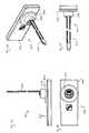
- FIG. 1A security hang tag 10 is shown in FIG. 1 .
- Security hang tag 10includes a body 12 , a rotatable head 14 and a strap 16 .
- Body 12is preferably formed as two separate pieces, or as a split-shell assembly, to allow an EAS marker to be disposed therein.
- Body 12may be closed via a snap-fit connection, glue, welding, or other such means.
- Strap 16may include a centrally-disposed region 17 having a reduced cross-sectional thickness. The centrally-disposed region 17 may be included in the strap to facilitate bending of the strap, to allow the strap to engage an item in a preferred manner or to provide a region for indicia or other viewable information.
- Strap 16is preferably formed of plastic.
- Head 14is secured to body 12 in a rotatable manner. More particularly, head 14 is preferably provided with a lip 18 which engages a circumferentially-extending flange 20 (as best seen in FIG. 5 ) located on an outwardly-opening head-receiving compartment 21 defined by body 12 . Lip 18 of head 14 is preferably positioned within compartment 21 of body 12 prior to the closure of such body. Once body 12 is closed to capture the EAS marker therein, lip 18 is also captured or disposed within compartment 21 of body 12 . It will be appreciated by those skilled in the art that such an arrangement allows the substantial majority of head 14 to extend beyond flange 20 , while allowing head 14 to rotate with respect to body 12 . It will be further appreciated that the disclosed configuration allows the substantial majority of body 12 to be formed with a slim profile, while also providing an assembly having a reduced number of components and which can be more readily/cost effectively manufactured.
- head 14is preferably insert molded as a single piece.
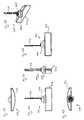
- head 14is provided with a pair of opposing strap-receiving channels 22 configured to receive the ends of the strap 16 .
- Each channel 22preferably includes a locking shoulder 24 , a ramped surface 26 and a pair of guide channels 23 , while each end of strap 16 includes a cavity 28 .
- a first end of the strap 16is inserted into a first channel 22 until shoulder 24 engages cavity 28 of the first end.
- the reduced cross-sectional area of tip 30together with ramping surface 26 and guide channels 23 , facilitate insertion of the strap into channel 22 , and subsequent engagement of shoulder 24 with cavity 28 .
- a second end of the strapis inserted into the second channel 22 of head 14 , engaging shoulder 24 with cavity 28 of the second end.
- the strapis engaged with head 14 in a non-removable manner.
- head 14is free to rotate with respect to body 12 , thereby reducing/eliminating the possibility that the security hang tag can be “twisted-off” the article in an unauthorized manner.
- the present security hang tagprovides a simplified design which facilitates the manufacture of its components, as well as the subsequent assembly of such components. This, of course, provides a security hang tag which can be produced at reduced cost. Moreover, the present security hang tag provides a design in which a plastic strap can be used as the securing member. In certain applications, the end user may desire straps having various color codes or other identifying indicia thereon. In addition, the design of the present security hang tag allows the end user to utilize the same body with straps of varying lengths. More particularly, the end user can be provided with an assortment of straps of various lengths whereby the end user can select a strap with an appropriate length for the particular application.
- Security hang tag 100includes a body 112 , a rotatable head 114 and a strap 116 .
- Security hang tag 100is similar in construction to security hang tag 10 , but includes some differences in the design of strap 116 and the design of head 114 .
- strap 116such strap may be formed with a continuous cross-sectional thickness, as compared to strap 16 .
- head 114such head includes a nose portion 150 , which protrudes outward from surface 152 .
- Strap-receiving channels 122are positioned on the sides of nose portion 150 , with each channel 122 including a pair of guide channels 123 .
- Head 114further includes a pair of ramping surfaces 126 and a pair of locking shoulders 124 .
- locking shoulder 124engages cavity 128 when strap 116 is inserted within channel 122 .
- the nose portion 150improves the pull-out strength of the head 114 with respect to the strap 116 because the locking shoulder 124 can have a larger cross-sectional area to restrain the strap 116 therein.
- FIGS. 21-25show details of shell 154 , which forms one-half of body 112 .
- head 114and particularly the inclusion of nose 150 which allows ramps 126 to extend beyond the surface 152 of the head 114 , facilitates insertion of the end of the strap 116 into the receiving channel 122 . It will be appreciated that such a construction also facilitates the manufacture of such components.
- FIGS. 33-57Another embodiment of the present invention is shown in FIGS. 33-57 . More particularly, a face-mounted swivel security hang tag 200 is shown in such figures.
- Security hang tag 200includes a body 212 , a rotatable head 214 and a strap 216 .
- Head 214 and strap 216are similar in design and construction to head 114 and strap 116 described hereinabove with respect to the second embodiment of the present invention. However, the orientation of head 214 and strap 216 with respect to body 212 is different from that described with respect to security hang tag 100 , as well as security hang tag 10 of the first embodiment.
- FIGS. 59-83Still another embodiment of the present invention, a horizontal security hang tag 300 , is shown in FIGS. 59-83 .
- Security hang tag 300includes a body 312 , a rotatable head 314 and a strap 316 .
- the construction of head 314 and strap 316is similar to head 114 and strap 116 described hereinabove with respect to the second embodiment of the present invention.
- FIGS. 65-68show details of head 314
- FIGS. 69-76shown details of the individual shell, i.e., shell 354 and shell 356 , which together form housing 312 .
- FIGS. 77-81show details of strap 316 .
- shells 354 and 356define a circumferentially-extending flange 320 located on an outwardly-opening head-receiving compartment 321 of the head 314 which captures lip 318 .
- one end of strap 316is received within a strap receiving channel 322 until shoulder 324 engages slot 328 of strap 316 .
- the security hang tagmay require the security hang tag to have a particular body configuration, such as the configuration shown in FIGS. 58-83 .
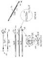
- FIGS. 84 and 85show a strap embodiment 416 that can be employed in any of the hang tag embodiments described hereinabove.
- Strap 416includes a centrally-disposed region 417 having a reduced cross-sectional area (i.e., square or round cross-section), a pair of cavities 428 and a pair of reduced cross-sectional area tips 430 .
- the centrally-disposed region 417may be included in the strap 416 to allow the strap to more easily engage certain articles or items.
- the reduced cross-sectional area tip 430includes a tongue 429 that tapers in a direction away from cavity 428 and a pair of opposing rails 431 that extend along at least a portion of the tongue 429 and which help to better direct the strap 416 along the ramped surfaces of the head until cavity 428 engages the locking shoulders located in the head.
- FIGS. 87-92show a strap embodiment 516 that can also be employed in any of the hang tag embodiments described hereinabove.
- Strap 516includes a centrally-disposed region 517 having a reduced cross-sectional area, a pair of cavities 528 and a pair of reduced cross-sectional area tips 530 .
- the reduced cross-sectional area tip 530includes a tongue 529 that tapers in a direction away from cavity 528 and a pair of opposing rails 531 that extend along at least a portion of the tongue 529 and which help to better direct the strap 516 along the ramped surfaces of the head until cavity 528 engages the locking shoulders located in the head.
Landscapes
- Engineering & Computer Science (AREA)
- Physics & Mathematics (AREA)
- General Physics & Mathematics (AREA)
- Theoretical Computer Science (AREA)
- Computer Hardware Design (AREA)
- Microelectronics & Electronic Packaging (AREA)
- Burglar Alarm Systems (AREA)
- Package Frames And Binding Bands (AREA)
Abstract
Description
Claims (17)
Priority Applications (1)
| Application Number | Priority Date | Filing Date | Title |
|---|---|---|---|
| US12/539,183US8453937B2 (en) | 2008-08-13 | 2009-08-11 | Security hang tag with swivel head |
Applications Claiming Priority (2)
| Application Number | Priority Date | Filing Date | Title |
|---|---|---|---|
| US8856108P | 2008-08-13 | 2008-08-13 | |
| US12/539,183US8453937B2 (en) | 2008-08-13 | 2009-08-11 | Security hang tag with swivel head |
Publications (2)
| Publication Number | Publication Date |
|---|---|
| US20100038431A1 US20100038431A1 (en) | 2010-02-18 |
| US8453937B2true US8453937B2 (en) | 2013-06-04 |
Family
ID=41680598
Family Applications (1)
| Application Number | Title | Priority Date | Filing Date |
|---|---|---|---|
| US12/539,183Expired - Fee RelatedUS8453937B2 (en) | 2008-08-13 | 2009-08-11 | Security hang tag with swivel head |
Country Status (2)
| Country | Link |
|---|---|
| US (1) | US8453937B2 (en) |
| MX (1) | MX2009008622A (en) |
Cited By (4)
| Publication number | Priority date | Publication date | Assignee | Title |
|---|---|---|---|---|
| US20130178081A1 (en)* | 2012-01-10 | 2013-07-11 | Ezconn Corporation | Signal connector anti-theft device set |
| WO2015073615A1 (en)* | 2013-11-15 | 2015-05-21 | Invue Security Products Inc. | Tethered security device for use with an electronic key |
| USD772492S1 (en)* | 2015-04-09 | 2016-11-22 | Brooks Equipment Company, Llc | Seal |
| US20170042346A1 (en)* | 2011-03-19 | 2017-02-16 | R&J Manufacturing Company | Anti-Theft Ring Assembly and Method of Using the Same |
Citations (50)
| Publication number | Priority date | Publication date | Assignee | Title |
|---|---|---|---|---|
| US3858280A (en)* | 1972-11-17 | 1975-01-07 | I D Engineering Inc | Fastening clip |
| US3932918A (en)* | 1973-06-01 | 1976-01-20 | Eaton Corporation | Releasably attachable clip |
| US3947930A (en)* | 1974-10-30 | 1976-04-06 | I. D. Engineering, Inc. | Anti-theft fastening device and tool for releasing same |
| US4393548A (en)* | 1980-08-04 | 1983-07-19 | Thomas & Betts Corporation | Folded head cable tie and methods for making and using the same |
| US5524463A (en)* | 1994-01-11 | 1996-06-11 | Sensormatic Electronics Corporation | Theft deterrent device to facilitate easy protection of large irregularly-shaped goods |
| US5788294A (en)* | 1997-02-04 | 1998-08-04 | E. J. Brooks Company | Tamper deterring seal |
| WO1998040591A1 (en) | 1997-03-11 | 1998-09-17 | Mathieu Aarts | An assembly, a method and a security device for securing and/or packaging a product temporarily |
| US5945909A (en)* | 1998-06-02 | 1999-08-31 | B&G Plastics, Inc. | Article identification and surveillance seal |
| US6102347A (en)* | 1997-09-03 | 2000-08-15 | Avery Dennison Corporation | Cable tie |
| US6188320B1 (en)* | 1999-07-29 | 2001-02-13 | B&G Plastics, Inc. | Article identification and surveillance tag having-article-engaging loop |
| US20010028308A1 (en)* | 1997-03-28 | 2001-10-11 | Carlos De La Huerga | Interactive medication container |
| US20020154014A1 (en)* | 2001-04-20 | 2002-10-24 | Steve Elston | One piece snap close anti-theft hang tag for merchandise |
| US20020171550A1 (en)* | 2001-05-16 | 2002-11-21 | Yuuki Hirose | Tag device |
| CN2572495Y (en) | 2002-09-27 | 2003-09-10 | 杭州思特利塑胶电子有限公司 | Article theft-proof locked fastener |
| US6624753B2 (en)* | 2001-01-30 | 2003-09-23 | World Color, Inc. | One piece snap close anti-theft hang tag for merchandise |
| US20040032332A1 (en)* | 2002-08-14 | 2004-02-19 | Mark Schiebler | Multi-use linkage device |
| USD492215S1 (en)* | 2003-06-02 | 2004-06-29 | Universal Surveillance Corpporation | Electronic article surveillance device |
| US20050128089A1 (en)* | 2003-10-29 | 2005-06-16 | Display Technologies, Inc. | Anti-theft tag |
| US6933847B2 (en)* | 2003-10-29 | 2005-08-23 | A&H Manufacturing, Co. | Anti-theft tag |
| US20050237205A1 (en)* | 2004-04-07 | 2005-10-27 | Sports-Tag Limited | Security tag device |
| US20060145873A1 (en)* | 2003-10-29 | 2006-07-06 | Display Technologies, Inc. | Rotating anti-theft tag |
| US20060170549A1 (en)* | 2005-01-14 | 2006-08-03 | Alpha Security Products, Inc. | Portable alarming security device |
| US20060202833A1 (en)* | 2005-02-28 | 2006-09-14 | B&G Plastics, Inc. | Hang tag with swivel attachment |
| US20070012772A1 (en)* | 2005-07-18 | 2007-01-18 | Cooper William J | Plastic case for an EAS tag |
| US20070120686A1 (en)* | 2005-11-29 | 2007-05-31 | Spagna Richard J | Lockable pinless EAS tag with lanyard |
| US7243963B2 (en)* | 2004-09-06 | 2007-07-17 | Elc Produtos De Seguranca Industria E Commercio Ltda. | Security seal |
| US20070234524A1 (en)* | 2006-04-07 | 2007-10-11 | Craig Witt | Dual lock zip tie |
| US20070273536A1 (en)* | 2004-12-22 | 2007-11-29 | Alpha Security Products, Inc. | Bottle security device |
| US20080016711A1 (en)* | 2006-07-19 | 2008-01-24 | Saphirwerk Industrieprodukte Ag | Stylus with integrated RFID chip |
| US7347068B2 (en)* | 2003-03-06 | 2008-03-25 | Stuart Seidel | Anti-theft device |
| USD566598S1 (en)* | 2006-09-27 | 2008-04-15 | Sayegh Adel O | Electronic article surveillance (EAS) tag with swiveling lanyard attachment |
| USD567128S1 (en)* | 2006-09-27 | 2008-04-22 | Sayegh Adel O | Electronic article surveillance (EAS) tag device with a lanyard |
| US20080165014A1 (en)* | 2007-01-05 | 2008-07-10 | Sayegh Adel O | Security tag having a swiveling engagement |
| USD578030S1 (en)* | 2007-10-31 | 2008-10-07 | Wg Security Products | EAS tag with lanyard |
| US20080316028A1 (en)* | 2005-11-29 | 2008-12-25 | Conti Brian V | Security device with perimeter alarm |
| US20090007470A1 (en)* | 2007-07-02 | 2009-01-08 | Robert Hill | Identification Tag and Releasable Attachment Clip |
| US20090102666A1 (en)* | 2005-12-28 | 2009-04-23 | Shute Matthew R | Merchandise tag with alarming features for securing tag to merchandise |
| US20090223260A1 (en)* | 2008-02-07 | 2009-09-10 | Checkpoint Systems, Inc. | Cable wrap security device |
| US20090294521A1 (en)* | 1997-03-28 | 2009-12-03 | Carlos De La Huerga | Interactive medication container labeling |
| US20090303046A1 (en)* | 2008-05-30 | 2009-12-10 | Checkpoint Systems, Inc. | Cable lock closure with defeat prevention |
| US7685850B2 (en)* | 2003-10-02 | 2010-03-30 | Mw Security Ab | Security wrapper |
| US20100089105A1 (en)* | 2006-01-13 | 2010-04-15 | Fawcett Christopher J | Bottle security device |
| US20100231388A1 (en)* | 2009-03-12 | 2010-09-16 | Checkpoint Systems, Inc. | Disposable cable lock and detachable alarm module |
| US20100271211A1 (en)* | 2009-04-25 | 2010-10-28 | Union Tool & Mold Company | Machine-washable ID label |
| US20110057042A1 (en)* | 2009-09-04 | 2011-03-10 | Airpointe Of New Hampshire, Inc. | Wearable data transceiver with coupled antenna |
| US20110095089A1 (en)* | 2009-10-28 | 2011-04-28 | B&G Plastics, Inc. | Electronic tag housing having cable tie support |
| US8016037B2 (en)* | 2004-04-15 | 2011-09-13 | National Oilwell Varco, L.P. | Drilling rigs with apparatus identification systems and methods |
| US20120019385A1 (en)* | 2009-03-04 | 2012-01-26 | Checkpoint Systems, Inc. | Multi-attach disposable tag |
| US8281626B2 (en)* | 2007-03-28 | 2012-10-09 | Checkpoint Systems, Inc. | Cable wrap security device |
| US20130008960A1 (en)* | 2011-07-08 | 2013-01-10 | Bray Gregory D | Systems and methods involving transferable identification tags |
- 2009
- 2009-08-11USUS12/539,183patent/US8453937B2/ennot_activeExpired - Fee Related
- 2009-08-12MXMX2009008622Apatent/MX2009008622A/enactiveIP Right Grant
Patent Citations (60)
| Publication number | Priority date | Publication date | Assignee | Title |
|---|---|---|---|---|
| US3858280A (en)* | 1972-11-17 | 1975-01-07 | I D Engineering Inc | Fastening clip |
| US3932918A (en)* | 1973-06-01 | 1976-01-20 | Eaton Corporation | Releasably attachable clip |
| US3947930A (en)* | 1974-10-30 | 1976-04-06 | I. D. Engineering, Inc. | Anti-theft fastening device and tool for releasing same |
| US4393548A (en)* | 1980-08-04 | 1983-07-19 | Thomas & Betts Corporation | Folded head cable tie and methods for making and using the same |
| US5524463A (en)* | 1994-01-11 | 1996-06-11 | Sensormatic Electronics Corporation | Theft deterrent device to facilitate easy protection of large irregularly-shaped goods |
| US5788294A (en)* | 1997-02-04 | 1998-08-04 | E. J. Brooks Company | Tamper deterring seal |
| WO1998040591A1 (en) | 1997-03-11 | 1998-09-17 | Mathieu Aarts | An assembly, a method and a security device for securing and/or packaging a product temporarily |
| US20010028308A1 (en)* | 1997-03-28 | 2001-10-11 | Carlos De La Huerga | Interactive medication container |
| US20090294521A1 (en)* | 1997-03-28 | 2009-12-03 | Carlos De La Huerga | Interactive medication container labeling |
| US6102347A (en)* | 1997-09-03 | 2000-08-15 | Avery Dennison Corporation | Cable tie |
| US5945909A (en)* | 1998-06-02 | 1999-08-31 | B&G Plastics, Inc. | Article identification and surveillance seal |
| US6188320B1 (en)* | 1999-07-29 | 2001-02-13 | B&G Plastics, Inc. | Article identification and surveillance tag having-article-engaging loop |
| US6624753B2 (en)* | 2001-01-30 | 2003-09-23 | World Color, Inc. | One piece snap close anti-theft hang tag for merchandise |
| US20020154014A1 (en)* | 2001-04-20 | 2002-10-24 | Steve Elston | One piece snap close anti-theft hang tag for merchandise |
| US20020171550A1 (en)* | 2001-05-16 | 2002-11-21 | Yuuki Hirose | Tag device |
| US20040032332A1 (en)* | 2002-08-14 | 2004-02-19 | Mark Schiebler | Multi-use linkage device |
| US20060144951A1 (en)* | 2002-08-14 | 2006-07-06 | Mark Schiebler | Multi-use linkage device |
| CN2572495Y (en) | 2002-09-27 | 2003-09-10 | 杭州思特利塑胶电子有限公司 | Article theft-proof locked fastener |
| US7347068B2 (en)* | 2003-03-06 | 2008-03-25 | Stuart Seidel | Anti-theft device |
| USD492215S1 (en)* | 2003-06-02 | 2004-06-29 | Universal Surveillance Corpporation | Electronic article surveillance device |
| US7685850B2 (en)* | 2003-10-02 | 2010-03-30 | Mw Security Ab | Security wrapper |
| US7626501B2 (en) | 2003-10-29 | 2009-12-01 | Display Technologies, Inc. | Anti-theft tag |
| US7518521B2 (en)* | 2003-10-29 | 2009-04-14 | Display Technologies, Inc. | Rotating anti-theft tag |
| US6933847B2 (en)* | 2003-10-29 | 2005-08-23 | A&H Manufacturing, Co. | Anti-theft tag |
| US20050128089A1 (en)* | 2003-10-29 | 2005-06-16 | Display Technologies, Inc. | Anti-theft tag |
| US20060145873A1 (en)* | 2003-10-29 | 2006-07-06 | Display Technologies, Inc. | Rotating anti-theft tag |
| US7227467B2 (en) | 2003-10-29 | 2007-06-05 | Display Technologies, Inc. | Anti-theft tag |
| US20050237205A1 (en)* | 2004-04-07 | 2005-10-27 | Sports-Tag Limited | Security tag device |
| US8016037B2 (en)* | 2004-04-15 | 2011-09-13 | National Oilwell Varco, L.P. | Drilling rigs with apparatus identification systems and methods |
| US7243963B2 (en)* | 2004-09-06 | 2007-07-17 | Elc Produtos De Seguranca Industria E Commercio Ltda. | Security seal |
| US20070273536A1 (en)* | 2004-12-22 | 2007-11-29 | Alpha Security Products, Inc. | Bottle security device |
| US20060170549A1 (en)* | 2005-01-14 | 2006-08-03 | Alpha Security Products, Inc. | Portable alarming security device |
| US20070146144A1 (en)* | 2005-02-28 | 2007-06-28 | B&G Plastics, Inc. | Hang tag with swivel attachment |
| US7183914B2 (en)* | 2005-02-28 | 2007-02-27 | B & G Plastics, Inc. | Hang tag with swivel attachment |
| US20060202833A1 (en)* | 2005-02-28 | 2006-09-14 | B&G Plastics, Inc. | Hang tag with swivel attachment |
| US7456741B2 (en)* | 2005-02-28 | 2008-11-25 | B&G Plastics, Inc. | Hang tag with swivel attachment |
| US20070012772A1 (en)* | 2005-07-18 | 2007-01-18 | Cooper William J | Plastic case for an EAS tag |
| US20070120686A1 (en)* | 2005-11-29 | 2007-05-31 | Spagna Richard J | Lockable pinless EAS tag with lanyard |
| US7659817B2 (en)* | 2005-11-29 | 2010-02-09 | Checkpoint Systems, Inc. | Security device with perimeter alarm |
| US20080316028A1 (en)* | 2005-11-29 | 2008-12-25 | Conti Brian V | Security device with perimeter alarm |
| US20090102666A1 (en)* | 2005-12-28 | 2009-04-23 | Shute Matthew R | Merchandise tag with alarming features for securing tag to merchandise |
| US20100089105A1 (en)* | 2006-01-13 | 2010-04-15 | Fawcett Christopher J | Bottle security device |
| US20070234524A1 (en)* | 2006-04-07 | 2007-10-11 | Craig Witt | Dual lock zip tie |
| US20080016711A1 (en)* | 2006-07-19 | 2008-01-24 | Saphirwerk Industrieprodukte Ag | Stylus with integrated RFID chip |
| USD567128S1 (en)* | 2006-09-27 | 2008-04-22 | Sayegh Adel O | Electronic article surveillance (EAS) tag device with a lanyard |
| USD566598S1 (en)* | 2006-09-27 | 2008-04-15 | Sayegh Adel O | Electronic article surveillance (EAS) tag with swiveling lanyard attachment |
| US20080165014A1 (en)* | 2007-01-05 | 2008-07-10 | Sayegh Adel O | Security tag having a swiveling engagement |
| US7808390B2 (en)* | 2007-01-05 | 2010-10-05 | Adel Sayegh | Security tag having a swiveling engagement |
| US8281626B2 (en)* | 2007-03-28 | 2012-10-09 | Checkpoint Systems, Inc. | Cable wrap security device |
| US20090007470A1 (en)* | 2007-07-02 | 2009-01-08 | Robert Hill | Identification Tag and Releasable Attachment Clip |
| USD578030S1 (en)* | 2007-10-31 | 2008-10-07 | Wg Security Products | EAS tag with lanyard |
| US20090223260A1 (en)* | 2008-02-07 | 2009-09-10 | Checkpoint Systems, Inc. | Cable wrap security device |
| US20120223838A1 (en)* | 2008-02-07 | 2012-09-06 | Checkpoint Systems, Inc. | Cable wrap security device |
| US20090303046A1 (en)* | 2008-05-30 | 2009-12-10 | Checkpoint Systems, Inc. | Cable lock closure with defeat prevention |
| US20120019385A1 (en)* | 2009-03-04 | 2012-01-26 | Checkpoint Systems, Inc. | Multi-attach disposable tag |
| US20100231388A1 (en)* | 2009-03-12 | 2010-09-16 | Checkpoint Systems, Inc. | Disposable cable lock and detachable alarm module |
| US20100271211A1 (en)* | 2009-04-25 | 2010-10-28 | Union Tool & Mold Company | Machine-washable ID label |
| US20110057042A1 (en)* | 2009-09-04 | 2011-03-10 | Airpointe Of New Hampshire, Inc. | Wearable data transceiver with coupled antenna |
| US20110095089A1 (en)* | 2009-10-28 | 2011-04-28 | B&G Plastics, Inc. | Electronic tag housing having cable tie support |
| US20130008960A1 (en)* | 2011-07-08 | 2013-01-10 | Bray Gregory D | Systems and methods involving transferable identification tags |
Non-Patent Citations (1)
| Title |
|---|
| USS Corporation, "Ultra Grip: The Power of Steel and Technology", www.universalea.com; Published 2004. |
Cited By (11)
| Publication number | Priority date | Publication date | Assignee | Title |
|---|---|---|---|---|
| US20170042346A1 (en)* | 2011-03-19 | 2017-02-16 | R&J Manufacturing Company | Anti-Theft Ring Assembly and Method of Using the Same |
| US11096506B2 (en)* | 2011-03-19 | 2021-08-24 | A & H Mfg. Co. Llc | Anti-theft ring assembly and method of using the same |
| US20130178081A1 (en)* | 2012-01-10 | 2013-07-11 | Ezconn Corporation | Signal connector anti-theft device set |
| US9059528B2 (en)* | 2012-01-10 | 2015-06-16 | Ezconn Corporation | Signal connector anti-theft device set |
| WO2015073615A1 (en)* | 2013-11-15 | 2015-05-21 | Invue Security Products Inc. | Tethered security device for use with an electronic key |
| CN105723426A (en)* | 2013-11-15 | 2016-06-29 | Invue安全产品公司 | Tether Security Device for Electronic Keys |
| US20160284179A1 (en)* | 2013-11-15 | 2016-09-29 | Invue Security Products Inc. | Tethered security device for use with an electronic key |
| US10140824B2 (en)* | 2013-11-15 | 2018-11-27 | Invue Security Products Inc. | Tethered security device for use with an electronic key |
| US10535239B2 (en) | 2013-11-15 | 2020-01-14 | Invue Security Products Inc. | Tethered security device for use with an electronic key |
| US11804116B2 (en) | 2013-11-15 | 2023-10-31 | Invue Security Products Inc. | Tethered security device for use with an electronic key |
| USD772492S1 (en)* | 2015-04-09 | 2016-11-22 | Brooks Equipment Company, Llc | Seal |
Also Published As
| Publication number | Publication date |
|---|---|
| MX2009008622A (en) | 2010-03-23 |
| US20100038431A1 (en) | 2010-02-18 |
Similar Documents
| Publication | Publication Date | Title |
|---|---|---|
| US7183914B2 (en) | Hang tag with swivel attachment | |
| US7808390B2 (en) | Security tag having a swiveling engagement | |
| US8341985B2 (en) | Security device for ring products | |
| EP2590865B1 (en) | Tag for bottle neck having integral locking ring | |
| US8344891B2 (en) | Security hard tag with attachment clip and method for attaching and detaching | |
| US7602297B2 (en) | Bottle security device | |
| US8453937B2 (en) | Security hang tag with swivel head | |
| US10385591B2 (en) | EAS tag with shackle | |
| US8264350B2 (en) | Adjustable constraining adaptive insert for merchandise security tag and method thereof | |
| US20050062608A1 (en) | Anti-theft device for items having portions that can be surrounded by straps or the like | |
| US11350706B2 (en) | Securement for zippered luggage | |
| CN101809244B (en) | Tamper-resistant article security device and method | |
| US20170132891A1 (en) | Security Tag With Swivel Head | |
| US10413095B2 (en) | Earring security display hanger | |
| US7714721B1 (en) | Anti-theft ring tag | |
| US10026288B2 (en) | One time use tag | |
| CN206345218U (en) | Wine bottle guards against theft device with RFID tag | |
| GB2440420A (en) | Anti-theft item tag |
Legal Events
| Date | Code | Title | Description |
|---|---|---|---|
| AS | Assignment | Owner name:B&G INTERNATIONAL, INC.,NEW JERSEY Free format text:ASSIGNMENT OF ASSIGNORS INTEREST;ASSIGNORS:KOLTON, CHESTER;NORMAN, MICHAEL;STRASSBURGER, JAKE;REEL/FRAME:023218/0635 Effective date:20090902 Owner name:B&G INTERNATIONAL, INC., NEW JERSEY Free format text:ASSIGNMENT OF ASSIGNORS INTEREST;ASSIGNORS:KOLTON, CHESTER;NORMAN, MICHAEL;STRASSBURGER, JAKE;REEL/FRAME:023218/0635 Effective date:20090902 | |
| STCF | Information on status: patent grant | Free format text:PATENTED CASE | |
| FPAY | Fee payment | Year of fee payment:4 | |
| AS | Assignment | Owner name:B&G INTERNATIONAL PRODUCTS LTD., NEW JERSEY Free format text:ASSIGNMENT OF ASSIGNORS INTEREST;ASSIGNOR:B & G PLASTICS, INC.;REEL/FRAME:051763/0959 Effective date:20191231 | |
| AS | Assignment | Owner name:B&G INTERNATIONAL PRODUCTS LTD., HONG KONG Free format text:CORRECTIVE ASSIGNMENT TO CORRECT THE CORRECT RECEIVING PARTY DATA PREVIOUSLY RECORDED AT REEL: 051763 FRAME: 0959. ASSIGNOR(S) HEREBY CONFIRMS THE ASSIGNMENT;ASSIGNOR:B &G PLASTICS, INC.;REEL/FRAME:051920/0940 Effective date:20191231 | |
| FEPP | Fee payment procedure | Free format text:ENTITY STATUS SET TO UNDISCOUNTED (ORIGINAL EVENT CODE: BIG.); ENTITY STATUS OF PATENT OWNER: LARGE ENTITY | |
| MAFP | Maintenance fee payment | Free format text:PAYMENT OF MAINTENANCE FEE, 8TH YEAR, LARGE ENTITY (ORIGINAL EVENT CODE: M1552); ENTITY STATUS OF PATENT OWNER: LARGE ENTITY Year of fee payment:8 | |
| FEPP | Fee payment procedure | Free format text:MAINTENANCE FEE REMINDER MAILED (ORIGINAL EVENT CODE: REM.); ENTITY STATUS OF PATENT OWNER: LARGE ENTITY | |
| LAPS | Lapse for failure to pay maintenance fees | Free format text:PATENT EXPIRED FOR FAILURE TO PAY MAINTENANCE FEES (ORIGINAL EVENT CODE: EXP.); ENTITY STATUS OF PATENT OWNER: LARGE ENTITY | |
| STCH | Information on status: patent discontinuation | Free format text:PATENT EXPIRED DUE TO NONPAYMENT OF MAINTENANCE FEES UNDER 37 CFR 1.362 | |
| FP | Lapsed due to failure to pay maintenance fee | Effective date:20250604 |