US8453764B2 - System and method for monitoring and controlling underground drilling - Google Patents
System and method for monitoring and controlling underground drillingDownload PDFInfo
- Publication number
- US8453764B2 US8453764B2US12/698,125US69812510AUS8453764B2US 8453764 B2US8453764 B2US 8453764B2US 69812510 AUS69812510 AUS 69812510AUS 8453764 B2US8453764 B2US 8453764B2
- Authority
- US
- United States
- Prior art keywords
- vibration
- drill string
- bit
- drill
- operating parameters
- Prior art date
- Legal status (The legal status is an assumption and is not a legal conclusion. Google has not performed a legal analysis and makes no representation as to the accuracy of the status listed.)
- Active, expires
Links
Images


Classifications
- E—FIXED CONSTRUCTIONS
- E21—EARTH OR ROCK DRILLING; MINING
- E21B—EARTH OR ROCK DRILLING; OBTAINING OIL, GAS, WATER, SOLUBLE OR MELTABLE MATERIALS OR A SLURRY OF MINERALS FROM WELLS
- E21B44/00—Automatic control systems specially adapted for drilling operations, i.e. self-operating systems which function to carry out or modify a drilling operation without intervention of a human operator, e.g. computer-controlled drilling systems; Systems specially adapted for monitoring a plurality of drilling variables or conditions
- E—FIXED CONSTRUCTIONS
- E21—EARTH OR ROCK DRILLING; MINING
- E21B—EARTH OR ROCK DRILLING; OBTAINING OIL, GAS, WATER, SOLUBLE OR MELTABLE MATERIALS OR A SLURRY OF MINERALS FROM WELLS
- E21B47/00—Survey of boreholes or wells
- G—PHYSICS
- G01—MEASURING; TESTING
- G01H—MEASUREMENT OF MECHANICAL VIBRATIONS OR ULTRASONIC, SONIC OR INFRASONIC WAVES
- G01H1/00—Measuring characteristics of vibrations in solids by using direct conduction to the detector
- G01H1/003—Measuring characteristics of vibrations in solids by using direct conduction to the detector of rotating machines
- G—PHYSICS
- G01—MEASURING; TESTING
- G01V—GEOPHYSICS; GRAVITATIONAL MEASUREMENTS; DETECTING MASSES OR OBJECTS; TAGS
- G01V9/00—Prospecting or detecting by methods not provided for in groups G01V1/00 - G01V8/00
- G—PHYSICS
- G05—CONTROLLING; REGULATING
- G05B—CONTROL OR REGULATING SYSTEMS IN GENERAL; FUNCTIONAL ELEMENTS OF SUCH SYSTEMS; MONITORING OR TESTING ARRANGEMENTS FOR SUCH SYSTEMS OR ELEMENTS
- G05B13/00—Adaptive control systems, i.e. systems automatically adjusting themselves to have a performance which is optimum according to some preassigned criterion
- G05B13/02—Adaptive control systems, i.e. systems automatically adjusting themselves to have a performance which is optimum according to some preassigned criterion electric
- G05B13/04—Adaptive control systems, i.e. systems automatically adjusting themselves to have a performance which is optimum according to some preassigned criterion electric involving the use of models or simulators
- G05B13/048—Adaptive control systems, i.e. systems automatically adjusting themselves to have a performance which is optimum according to some preassigned criterion electric involving the use of models or simulators using a predictor
- G—PHYSICS
- G05—CONTROLLING; REGULATING
- G05B—CONTROL OR REGULATING SYSTEMS IN GENERAL; FUNCTIONAL ELEMENTS OF SUCH SYSTEMS; MONITORING OR TESTING ARRANGEMENTS FOR SUCH SYSTEMS OR ELEMENTS
- G05B23/00—Testing or monitoring of control systems or parts thereof
- G05B23/02—Electric testing or monitoring
- G05B23/0205—Electric testing or monitoring by means of a monitoring system capable of detecting and responding to faults
- G05B23/0218—Electric testing or monitoring by means of a monitoring system capable of detecting and responding to faults characterised by the fault detection method dealing with either existing or incipient faults
- G05B23/0243—Electric testing or monitoring by means of a monitoring system capable of detecting and responding to faults characterised by the fault detection method dealing with either existing or incipient faults model based detection method, e.g. first-principles knowledge model
- G—PHYSICS
- G06—COMPUTING OR CALCULATING; COUNTING
- G06F—ELECTRIC DIGITAL DATA PROCESSING
- G06F17/00—Digital computing or data processing equipment or methods, specially adapted for specific functions
- G06F17/10—Complex mathematical operations
- G06F17/18—Complex mathematical operations for evaluating statistical data, e.g. average values, frequency distributions, probability functions, regression analysis
- G—PHYSICS
- G05—CONTROLLING; REGULATING
- G05B—CONTROL OR REGULATING SYSTEMS IN GENERAL; FUNCTIONAL ELEMENTS OF SUCH SYSTEMS; MONITORING OR TESTING ARRANGEMENTS FOR SUCH SYSTEMS OR ELEMENTS
- G05B2219/00—Program-control systems
- G05B2219/20—Pc systems
- G05B2219/24—Pc safety
- G05B2219/24075—Predict control element state changes, event changes
- G—PHYSICS
- G05—CONTROLLING; REGULATING
- G05B—CONTROL OR REGULATING SYSTEMS IN GENERAL; FUNCTIONAL ELEMENTS OF SUCH SYSTEMS; MONITORING OR TESTING ARRANGEMENTS FOR SUCH SYSTEMS OR ELEMENTS
- G05B2219/00—Program-control systems
- G05B2219/20—Pc systems
- G05B2219/26—Pc applications
- G05B2219/2616—Earth moving, work machine
Definitions
- the present inventionrelates to underground drilling, and more specifically to a system and a method for monitoring and controlling the drilling operation, especially operation related to drill string vibration, so as to achieve optimum performance and life from the drill string.
- Underground drillingsuch as gas, oil, or geothermal drilling, generally involves drilling a bore through a formation deep in the earth. Such bores are formed by connecting a drill bit to long sections of pipe, referred to as a “drill pipe,” so as to form an assembly commonly referred to as a “drill string.”
- the drill stringextends from the surface to the bottom of the bore.
- the drill bitis rotated so that the drill bit advances into the earth thereby forming the bore.
- the drill bitis rotated by rotating the drill string at the surface.
- Piston-operated pumps on the surfacepump high-pressure fluid, referred to as “drilling mud,” through an internal passage in the drill string and out through the drill bit.
- the drilling mudlubricates the drill bit, and flushes cuttings from the path of the drill bit.
- the flowing mudalso powers a drilling motor, commonly referred to as a “mud motor,” which turns the bit, whether or not the drill string is rotating.
- the mud motoris equipped with a rotor that generates a torque in response to the passage of the drilling mud therethrough.
- the rotoris coupled to the drill bit so that the torque is transferred to the drill bit, causing the drill bit to rotate.
- the drilling mudthen flows to the surface through an annular passage formed between the drill string and the surface of the bore.
- the drilling environmentcan induce substantial vibration and shock into the drill string. Vibration also can be introduced by rotation of the drill bit, the motors used to rotate the drill bit, the pumping of drilling mud, imbalance in the drill string, etc. Such vibration can result in premature failure of the various components of the drill string, premature dulling of the drill bit, or may cause the drilling to be performed at less than optimum conditions.
- WOBweight on bit
- drill bitsare typically designed for a predetermined range of rotary speed and WOB and do not perform as effectively if operated outside this range in order to avoid excessive vibration.
- a drill stringmay experience various types of vibration.
- “Axial vibration”refers to vibration in the direction along the drill string axis.
- “Lateral vibration”refers to vibration perpendicular to the drill string axis. Lateral vibration often arises because the drill string rotates in a bent condition.
- Two other sources of lateral vibrationare “forward” and “backward”, or “reverse”, whirl.
- “Whirl”refers to a situation in which the bit orbits around the bore hole in addition to rotating about its own axis. In backward whirl, the bit orbits in a direction opposite to the direction of rotation of the drill bit.
- Stick-slipoccurs when the drill bit or lower section of the drill string momentarily stops rotating (i.e., “sticks”) while the drill string above continues to rotate, thereby causing the drill string to “wind up,” after which the stuck element “slips” and rotates again. Often, the bit will over-speed as it unwinds.
- the rate of penetrationis a function of a number of variables, including the rotational speed of the drill bit and the WOB.
- surface equipmentsenses the rate of penetration of the drill bit into the formation, the rotational speed of the drill string, the hook load, surface torque, and pressure. Sensors either at the surface or in a bottomhole assembly (“BHA”), or both, measure the axial tensile/compression load, torque and bending.
- APS Technology's SureShotTM surface systemreceive and process information from sensors near the bit, such as WOB sensors, torque sensors, inclination sensors (i.e., accelerometers) and azimuth sensors (i.e., magnetometers), and transmit the information to other surface equipment.
- sensors near the bitsuch as WOB sensors, torque sensors, inclination sensors (i.e., accelerometers) and azimuth sensors (i.e., magnetometers), and transmit the information to other surface equipment.
- a surface estimate of WOBmay also be derived from hook load and drag calculations.
- the SureShotTM systemalso receives data on the mud flow rate from other surface software. Typically, such software determines the mud flow rate from a curve provided by the mud pump supplier relating flow rate to stroke rate of the pump pistons, rather than from a direct flow rate sensors.
- the surface softwareuses a curve of mud motor flow rate versus motor RPM or an RPM/flow rate factor, the surface software also determines the mud motor RPM.
- the SureShotTM systemalso calculates the build rate, normally expressed as degrees per 100 feet or degrees per 30 meters, based on the change in inclination measured by the accelerometers for the depth drilled. It also calculates the turn rate, normally expressed as degrees per 100 feet or degrees per 30 meters, based on the change in azimuth (i.e., the lateral direction of drilling) measured by the magnetometers.
- the build ratenormally expressed as degrees per 100 feet or degrees per 30 meters, based on the change in azimuth (i.e., the lateral direction of drilling) measured by the magnetometers.
- azimuthi.e., the lateral direction of drilling
- Vibration Memory ModuleTMprocesses data from accelerometers and magnetometers installed into the bottomhole assembly to determine the amplitudes of axial vibration, and of lateral vibration due to forward and backward whirl, at the location of these sensors.
- the Vibration Memory ModuleTMalso determines torsional vibration due to stick-slip by measuring and recording the maximum and minimum instantaneous RPM over a given period of time, such as every four seconds, based on the output of the magnetometers.
- the amplitude of torsional vibration due to stick-slipis then determined by determining the difference between and maximum and minimum instantaneous rotary speeds of the drill string over the given period of time.
- root-mean-square and peak values for the axial, lateral and torsional vibrationsare recorded at predetermined intervals, such as every four seconds.
- the amplitudes of the axial, lateral and torsional vibrationare transmitted to the surface via mud pulse telemetry.
- Vibration Memory ModuleTMMost systems, including the aforementioned Vibration Memory ModuleTM, don't measure the frequency of the vibration, although some high end tools do. Insofar as the inventors are aware, none of the current tools, however, transmit the vibration frequency to the surface. However, when using the Vibration Memory ModuleTM, burst data samples, recorded either as a result of the occurance of an event or at preselected time periods, may be down loaded from the Vibration Memory ModuleTM after a run is completed and the BHA assembly is pulled out of the hole. Software at the surface can read the burst sample data, plot it and performs a Fourier analysis to determine the frequency of the vibration.
- the WellDrillTM systememploys software that uses finite element techniques, in particular ANSYS software, to model the drill string based on the drill string geometry and mechanical properties. As shown in FIG. 1 , the model is comprised of beam elements 53 , connected by nodes 54 , and contact elements 55 . As shown in FIG. 2 , the entire drill string 4 —including a drill bit 8 , mud motor 40 , stabilizers 41 , drill collars 43 , Measurement While Drilling (“MWD”) tool 56 —is modeled by a series of beam elements, nodes and contact elements.
- MWDMeasurement While Drilling
- a beam element 53is shown in FIG. 3A and comprises a uniaxial element with tension, compression, torsion, and bending capabilities. These elements have six degrees of freedom at each node: translations in the nodal x, y and z directions and rotations about the nodal x, y and z axes. Stress stiffening and large deflection capabilities are also included.
- the gaps between drill string components and the boreholeare modeled using contact elements, each of which represents two surfaces which may maintain or break physical contact and may slide relative to each other.
- a contact element 55shown in FIG.
- 3Bis capable of supporting only compression in the direction normal to the surfaces and shear (Coulomb) friction in the tangential direction, and have two degrees of freedom at each node: translations in the nodal x and y directions. Force and displacement constraints are applied to a node at each end of a drill string element and a contact element is attached to each node. The drill string is allowed to deflect laterally until it contacts the surface modeled by the contact element.
- the WellDrillTM model of the drill stringis created by entering data into the software to specify:
- Strikeis defined as the compass direction, relative to north, of the line formed by the intersection of a rock layer or other planar feature with an imaginary horizontal plane.
- the intersection of two flat planesis a straight line, and in this instance, the line is geologic strike.
- the compass direction (or bearing) of this lineis always measured and referred to relative to north.
- a typical bearingis given, for example, as N 45° E, which is a shorthand notation for a bearing that is 45° east of north (or half way between due north and due east). The only exception to this north rule occurs where strike is exactly east-west. Then, and only then, is a strike direction written that is not relative to north.
- Dipas a part of the measurement of the attitude of a layer or planar feature, has two components: dip direction and dip magnitude.
- Dip directionis the compass direction (bearing) of maximum inclination of the layer or planar feature down from the horizontal and is always perpendicular (i.e., at a 90° angle) to strike.
- Dip magnitudeis the smaller of the two angles formed by the intersection of the dipping layer or planar feature and the imaginary horizontal plane. However, dip magnitude can also be equal to either zero or 90°, where the layer or planar feature is horizontal or vertical, respectively.
- the WellDrillTM softwarecalculates the static deflection shape of the drill string so as to determine the points of contact between the drill string and the bore hole.
- dataare also entered into the WellDrillTM software specifying the expected operating parameters for (i) the WOB, (ii) the drill string RPM, (iii) the mud motor RPM, (iv) the diameter of the bore hole, and (v) the damping coefficient.
- the damping coefficientis calculated using a predetermined values of the viscosity of oil or water (depending on whether the operator indicates that an oil-based or water-based drilling mud is used), the density of the fluid (mud weight), and the annulus between the BHA and the bore hole.
- the bore hole diameteris estimated based on the diameter of the drill bit and the type of formation in lieu of not having caliper data.
- the diameter of the bore holemay be estimated to be 1 ⁇ 2 inch larger than the diameter of the drill bit, whereas it may be estimated to be much larger than the drill bit for soft rock. (The maximum diameter is based on the number of cones or blades on the bit.) The diameter of the bore hole is also generally assumed to be bigger if a bent sub is used for rotary directional drilling.
- the WellDrillTM softwareperforms static bending analysis to determine contact points between the drill string and the borehole. This provides support information for the vibration analysis.
- the static bending analysisdetermines the deflection, contact points, bending moments and the bending stress along the length of the drill string.
- the bending analysisis used to determine the predicted build and turn rate.
- the build ratesare determined by a force balance at the drill bit.
- the critical speedsare determined by performing a forced harmonic frequency sweep. Excitation forces are applied at the bit and the power section of the mud motor. Wherever the excitation forces are near natural frequencies of the drill string, critical speeds occur.
- the WellDrillTM softwareperforms a forced response analysis by applying an oscillating WOB over selected range of WOBs and drill bit RPMs.
- the selected oscillating WOBis applied at two frequencies: (i) the rotary speed of the drill bit and (ii) the number of cones (for roller cone bits) or blades (for PDC bits) multiplied by the drill bit speed.
- mud motors rotorsare eccentric by design, they always create an oscillating imbalance force, the magnitude of which is based on the rotor eccentricity and the frequency of which is equal to N(n+1), where n is the number of lobes on the rotor and N is the mud motor rotor RPM.
- the softwareincludes in the forced response analysis an oscillating imbalance force based on the characteristics of the mud motor applied at frequencies based on a selected range of mud motor RPM.
- Typical drill string rotary speedsare 10-250 rpm, while mud motor speeds may be 50-250 rpm.
- the typical bit speed(combination of motor and rotary speeds) is, therefore, 60 to 500 rpm.
- Mud turbinesoperate at much higher speeds of 800-1500 rpm, but do not introduce a similar imbalance.
- Drill collarsmay also have features, such as electronics hatches, upsets and cutout, that create a rotating imbalance.
- drill collars that become bent in servicecreate a rotating imbalance. Since such rotating imbalances are a source of vibration excitation, WellDrillTM can include them in the model.
- the WellDrillTM softwarepredicts critical drilling speeds for the drill string, motor and bit.
- Critical speedsoccur when the drilling forces excite the drill string such that the induced vibration causes damage to the drill string and/or results in lost drilling performance.
- Drilling forces that may excite the drilling and induce critical speedsinclude: bit forces from the blades or cones of the bit striking a discontinuity, bit whirling in an over gauge bore hole, the imbalance forces generated by the motor stator, imbalance forces from the drill string the drill string contacting the bore hole resulting in whirling, and under-gauge stabilizers whirling.
- the frequency of the excitation forceis at or near a natural frequency of the drill string, the displacement amplitudes are easier to excite.
- the excitation forces away from the natural frequenciesmay be severe enough to damage the drillstring and require their identification as critical speeds.
- WellDrillTMuses the calculated torque to determine torsional vibrations by determining whether the torque applied to the drill bit is sufficient to rotate the drill string backward. If this condition is present then it is considered a torsional critical speed. WellDrillTM also uses the calculated torque to determine stick-slip conditions, in particular, whether the torque along the drill string is sufficient to overcome frictional resistance to rotation.
- the previously used stick-slip prediction softwarebreaks up the drill string into finite lengths, typically less than thirty feet.
- the drag on each sectionis a function of the normal force the section exerts on the wall of the borehole and the coefficient of sliding friction between the drill string and the wall.
- the normal forceis a function of the curvature of the drill string section, the tension in the section, and gravity effects.
- the coefficient of frictionis primarily a function of the characteristics of the drilling mud and whether the borehole is cased or open. Its value can be empirically developed by, for example, applying the model to a drill string in which the pickup weight, slack-off weight and torque are measured to establish independent measurements of drag.
- the calculationsstart at the surface with an initial rotary speed of 0 rpm.
- the softwareuses the static friction coefficient when the pipe is stationary, and the sliding friction coefficient when it is moving relative to the borehole (sliding and/or rotating). Normally the static friction is higher than the sliding friction.
- the softwarecalculates the torsional deflection in each section as a result of the incremental torque, ⁇ M, based on the mechanical properties of the section.
- the section propertiesdepend on the outside and inside diameters of the section and its material density. These define the mass of the section and the rotational inertia of each section. If the sum of the incremental torques necessary to overcome the drag is greater than the torque applied to the drill string, at the surface, then the drill bit will “stick.”
- the softwaredetermines what values of WOB and drill string RPM, will result in stick-slip.
- the softwarecalculates the rotary inertia—that is, the incremental time it will take each section to deflect by that amount based on the mechanical properties of the section, in particular, the inside and outside diameter of the section and its mass, the applied torque and friction.
- the sum of these time increments over the length of the drill stringrepresents the change in the instantaneous speed of the drill string, which is reported to operating personal for use, for example, in operating a rotary steerable tool or ensuring that the operating conditions are not damaging the drill bit.
- the inventionencompasses a method, which may be computer implemented, of monitoring the operation of a drill string drilling into an earthen formation so as to form a bore hole using a drill bit, comprising the steps of: (a) drilling a bore hole having a first diameter in the earthen formation by rotating the drill bit at a first rotary speed and applying a first weight on the bit; (b) making a determination of the value of the first rotary speed at which the drill bit rotates; (c) making a determination of the value of the first weight on the bit; (d) making a determination of the value of the first diameter of the bore hole; (d) measuring vibration in the drill string at least one predetermined location along said drill string while rotating said drill bit at said first speed and applying the first weight on the bit; (e) using a finite element model of the drill string to predict the vibration in the drill string at the at least one predetermined location based on the determined values of the first rotary speed of the drill bit, the first weight on bit and the first bore hole diameter; (f)
- the inventionencompasses a method, which may be computer implemented, for monitoring the operation of a drill string drilling into an earthen formation so as to form a bore hole using a drill bit located in a bottom hole assembly, comprising the steps of: a) determining the values of a plurality of operating parameters associated with the underground drilling operation by taking measurements from a plurality of sensors, at least a portion of the sensors located in the bottom hole assembly; b) determining from the determined values of the operating parameters whether each of a plurality of predetermined symptoms of lost drilling performance are present in the drilling operation; c) identifying the probability that each of the parameters determined to be present in the drilling operation are caused by each of a plurality of predetermined causes of lost drilling performance; d) combining the identified probabilities for each of the predetermined causes of lost drilling performance so as to determine the most likely cause of lost drilling performance present in the drilling operation.
- the inventionencompasses a method, which may be computer implemented, for monitoring the operation of a drill string drilling into an earthen formation so as to form a bore hole using a drill bit, comprising the steps of a) operating the drill string at a first set of operating parameters, the first set of operating parameters comprising the speed at which the drill bit rotates; b) determining the values of the parameters in the first set of operating parameters; c) inputting the determined values of the parameters in the first set of operating parameters into a finite element model of the drill string; d) using the finite element model of the drill string with the inputted values of the parameters to determine at least a portion of the vibratory mode shape of the drill string when operating at the first set of operating parameters; e) using the portion of the vibratory mode shape to determine the relationship between the amplitude of vibration at the first location to the amplitude of vibration at a second location when operating at the first set of operating parameters; f) measuring the amplitude of vibration of the drill string at the second location when operating at the first
- the inventionencompasses a method, which may be computer implemented, for monitoring the operation of a drill string drilling into an earthen formation so as to form a bore hole using a drill bit, comprising the steps of: a) applying a torque to the drill string at a location proximate the surface of the earth so as to rotate the drill string, the drill string undergoing angular deflection between the drill bit and the location at which the torque is applied; b) determining the values of parameters in a first set of operating parameters associated with the rotation of the drill string; c) inputting the determined values of the parameters in the first set of operating parameters into a finite element model of the drill string; d) using the finite element model of the drill string with the inputted values of the parameters to determine the angular deflection in the drill string at at least first and second locations along the length of the drill string when operating at the first set of operating parameters; e) using the angular deflections at the first and second locations along the drill string to determine the relationship between the torque on
- the inventionencompasses a method, which may be computer implemented, for monitoring the operation of a drill string drilling into an earthen formation so as to form a bore hole using a drill bit, comprising the steps of: a) rotating the drill bit at a first rotary speed so that the drill bit forms a bore hole in the earthen formation, the drill string vibrating in a lateral vibration mode; b) generating a signal representative of the vibration of the drill string in the lateral vibration mode as the drill bit drills into the earthen formation; c) analyzing the signal so as to determine the backward whirl frequency of the vibration of the drill string in the lateral vibration mode; d) determining the diameter of the bore hole being drilled by the drill bit from the backward whirl frequency.
- the inventionencompasses a method, which may be computer implemented, for monitoring the operation of a drill string drilling into an earthen formation so as to form a bore hole using a drill bit, comprising the steps of: a) determining a set of operating parameters for the drill string that will result in the maximum rate of penetration of the drill bit into the earthen formation; b) inputting the set of operating parameters into a finite element model of the drill string; and c) using the finite element model with the inputted set of operating parameters to predict the vibration in the drill string that will result from operation of the drill string according to the set of operating parameters.
- the inventionencompasses a method, which may be computer implemented, for monitoring the operation of a drill string drilling into an earthen formation so as to form a bore hole using a drill bit, comprising the steps of: a) obtaining a data base relating sets of operating parameters for the drill string to rates of penetration of the drill bit into the earthen formation when operating at the sets of operating parameters; b) using a finite element model of the drill string and the data base to predict the maximum rate of penetration of the drill string into the earthen formation that will not result in the vibration in the drill string violating a predetermined criteria.
- the inventionencompasses a computer-readable storage medium having stored thereon computer-exectuable instructions for performing the aforementioned methods.
- FIG. 1is a schematic diagram of a finite element model used to model a drill string.
- FIG. 2is a schematic diagram of a finite element model of a drill string.
- FIGS. 3A and Bare schematic diagrams of beam and contact elements used in the finite element model of the drill string.
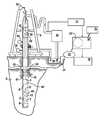
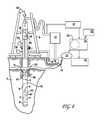
- FIG. 4is a view, partly schematic, of a drilling rig incorporating the current invention.
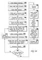
- FIG. 5Ais a flowchart of the method of operating a drill string that is the subject of the current invention.
- FIG. 5Bis a flowchart of the method of creating a model of the drill string using the WellDrillTM software.
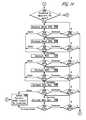
- FIG. 6is a flowchart of a method for revising the drill string model to reduce deviations between predicted and measured critical speeds.
- FIG. 7is a hypothetical vibratory mode shape curve generated using the software of the current invention.
- FIG. 8is a hypothetical critical speed map created by the software of the current invention.
- FIG. 9is a flowchart of the method of identifying the cause of loss of drilling performance according to the current invention.
- FIGS. 10-12are flowcharts of the method of mitigating lost performance in drill performance, due to vibration, according to the current invention.
- FIG. 13is a flowchart of the method for revising the drill string model to reduce deviations between predicted and measured vibration, following mitigation of lost drilling performance due to vibration, according to the current invention.
- FIG. 14is a flowchart of the method for revising the model to reduce deviations between predicted and measured vibration when mitigation of a loss of drilling performance due to vibration has not been attempted, according to the current invention.
- FIG. 15is a flowchart of the method for operating at the maximum rate of penetration that avoids excessive vibration.
- drill rigstypically comprise a derrick 9 that supports a drill string 4 .
- a drill bit 8is coupled to the distal end of a bottomhole assembly 6 of the drill string 4 .
- a prime mover(not shown), such as a top drive or rotary table, rotates the drill string 4 so as to control the rotational speed (RPM) of, and torque on, the drill bit 8 .
- RPMrotational speed
- a pump 10pumps a fluid 14 —typically referred to as drilling mud—downward through an internal passage in the drill string. After exiting at the drill bit 8 , the returning drilling mud 16 flows upward to the surface through an annular passage formed between the drill string 4 and the bore hole 2 in the earthen formation 3 .
- a mud motor 40such as a helicoidal positive-displacement pump—sometimes referred to as a “Moineau-type” pump—may be incorporated into the bottomhole assembly 6 and is driven by the flow of drilling mud 14 through the pump.
- a helicoidal positive-displacement pumpis described more fully in U.S. Pat. No. 6,102,681, entitled “Stator Especially Adapted For Use In A Helicoidal Pump/Motor,” hereby incorporated by reference herein in its entirety.
- downhole strain gauges 7are incorporated into the bottomhole assembly 6 to measure the WOB.
- a system for measuring WOB using downhole strain gaugesis described in U.S. Pat. No. 6,547,016, entitled “Apparatus For Measuring Weight And Torque An A Drill Bit Operating In A Well,” hereby incorporated by reference herein in its entirety.
- downhole sensorssuch as strain gauges, measuring the torque on bit (“TOB”) and the bending on bit (“BOB”) are also included in the bottomhole assembly. Techniques for downhole measurement of TOB are also described in the aforementioned U.S. Pat. No. 6,547,016, incorporated by reference above.
- WTB subA sub incorporating WOB, TOB and BOB sensors is referred to as a “WTB sub.”
- a magnetometer 42is incorporated into the bottomhole assembly 6 that measures the instantaneous rotational speed of the drill bit 8 , using, for example, the techniques in U.S. Pat. No. 7,681,663, entitled “Methods And Systems For Determining Angular Orientation Of A Drill String,” hereby incorporated by reference herein in its entirety.
- Accelerometers 44oriented along the x, y, and z axes (typically with ⁇ 250 g range), are incorporated into the bottomhole assembly 6 that, using techniques well known in the art, measure axial and lateral vibration. Although accelerometers 44 are shown in only one location in FIG. 4 , as is conventional, sets of three x, y, z accelerometers would be installed at various locations along the drill string 4 .
- a Vibration Memory ModuleTM 46is preferably incorporated into the bottomhole assembly 6 . It receives data from the accelerometers 44 installed into the bottomhole assembly 6 , from which it determines the amplitude and frequency of axial vibration, and of lateral vibration due to forward and backward whirl, at the location of the accelerometers. These values are transmitted to the surface via a mud pulse telemetry system, discussed below. Alternatively, the information could be transmitted to the surface using a wired pipe system, such as Intellipipe, or other means such as acoustic or electromagnetic transmission.
- the Vibration Memory ModuleTM 46also receives data from the magnetometer 42 incorporated into the bottomhole assembly 6 , from which it measures the instantaneous rotational speed of the drill string at the magnetometer 42 location. It then determines the amplitude and frequency of torsional vibration due to stick-slip by determining the difference between and maximum and minimum instantaneous rotational speed of the drill string over a given period of time. This information is also transmitted to the surface via the mud pulse telemetry system.
- a memory device 47such as a micro-chip, is incorporated into the Vibration Memory ModuleTM 46 to record the fatigue life remaining in the component, as discussed in section 10, below, concerning life prediction.
- pressure sensors 51 and 52are incorporated into the Vibration Memory ModuleTM 46 that measure the pressure of the drilling mud flowing through the drill string and the pressure of the drilling mud flowing through the annular gap between the bore hole wall and the drill string, respectively.
- the WOBis controlled by varying the hook load on the derrick 9 .
- a top sub 45is incorporated at the top of the drill string and encloses strain gauges 48 that measure the axial (hook) load, as well as the bending and torsional load on the top sub, and a triaxial accelerometer 49 that senses vibration of the drill string.
- the WOBcan be calculated from the hook load measured by the strain gauges in the top sub, for example, by subtracting the frictional resistance acting on the drill string from the measured hook load. The value of the frictional resistance can be obtained by pulling up on the drill string so that the drill bit is no longer contacting the formation and noting the change in the hook load.
- the data from the downhole sensorswould be received by the top sub 45 .
- the data from the top sub 45 strain gauges, as well as the downhole sensors in a wired pipe system,can be transmitted via wireless telemetry to the surface acquisition system 12 using the technique disclosed in U.S. application Ser. No. 12/389,950, filed Feb. 20, 2009, entitled “Synchronized Telemetry From A Rotating Element,” hereby incorporated by reference in its entirety.
- the surface monitoring systemalso includes a hook load sensor 30 for determining WOB.
- the hook load sensor 30measures the hanging weight of the drill string, for example, by measuring the tension in the draw works cable using a strain gauge.
- the cableis run through three supports. The supports put a known lateral displacement on the cable.
- the strain gaugemeasures the amount of lateral strain due to the tension in the cable, which is then used to calculate the axial load.
- a sensor 32is also used for sensing drill string rotational speed.
- the drilling operation according to the current inventionalso includes a mud pulse telemetry system, which includes a mud pulser 5 incorporated into the downhole assembly 6 .
- the mud pulse telemetry systemencodes data from downhole equipment, such as vibration information from the Vibration Memory ModuleTM, and, using the pulser 5 , transmits the coded pulses to the surface.
- Mud pulse telemetry systemsare described more fully in U.S. Pat. No. 6,714,138, entitled “Method And Apparatus For Transmitting Information To The Surface From A Drill String Down Hole In A Well,” U.S. Pat. No.
- vibration amplitudecan reported as 0, 1, 2 or 3 to indicate normal, high, severe, or critical vibration, respectively.
- One method that may be employed to report frequencyis to assign numbers 1 through 10, for example, to values of the vibration frequency so that a value of 1 indicates a frequency in the 0 to 100 hz range, a value of 2 indicates frequency in the 101 to 200 hz range, etc.
- the mode of vibrationmay be reported by assigning a number 1 through 3 so that, for example, a value of 1 indicates axial vibration, 2 indicates lateral vibration, and 3 indicates torsional vibration.
- a data acquisition system 12such as a SureShotTM system, discussed above, at the surface senses pressure pulsations in the drilling mud 14 created by the mud pulser 5 that contain encoded information from Vibration Memory ModuleTM and other sensors in the bottomhole assembly 6 .
- the data acquisition system 12decodes this information and transmits it to a computer processor 18 , also preferably located at the surface. Data from the surface sensors, such as the hook load sensor 30 , the drill string rotational speed sensor 32 , and the ROP sensor 34 are also transmitted to the processor 18 .
- Software 20which includes the WellDrillTM software and stick-slip software discussed above, as well as software for performing the methods described herein, discussed below, is preferably stored on a non-transitory computer readable medium, such as a CD, and installed into the processor 18 that executes the software so as to perform the methods and functions discussed below.
- the processor 18is preferably connected to a display 19 , such as a computer display, for providing information to the drill rig operator.
- a data entry device 22such as a keyboard, is also connected to the processor 18 to allow data to be entered for use by the software 20 .
- a memory device 21is in communication with the processor 18 so that the software can send to data to, and receive data from, storage when performing its functions.
- the processor 18may be a personal computer that preferably has at least a 16 ⁇ CD-ROM drive, 512 MB RAM, 225 MB of free disk space, a graphics card and monitor capable of 1024 ⁇ 786 or better at 256 colors and running a Windows XPTM operating system.
- the processor 18 executing the software 20 of the current inventionis preferably located at the surface and can be accessed by operating personnel, portions of the software 20 could also be installed into a processor located in the bottomhole assembly so that some of the operations discussed below, such as a Fourier analysis of vibration data, could be performed downhole.
- the current inventionmakes use of the WellDrillTM software, discussed above.
- WeIIDrillTMcan be employed in performing the methods of the current invention because it does a much better job of modeling the sources of vibration and the excitation forces than other programs. Most other programs predict the fundamental natural frequencies and base the mode shapes on this but do not take into account the whether the amplitudes and accelerations are sufficient to cause damage.
- WellDrillTMrelies on a forced harmonic analysis that accurately models the excitation forces and their applied frequencies. It also considers additional sources of vibration such as mud motor imbalances, bent collars and drill string imbalances.
- step 100the operator begins by specifying the significant drill string components—such as a Measurement While Drilling (“MWD”) tool—and the vibration limits applicable to each such component.
- MWDMeasurement While Drilling
- step 102the data input into WellDrillTM may include:
- the information on the drill string componentscan also be updated by the operator each time a new section of drill string is added.
- dataare also entered into the WellDrillTM software specifying the expected operating parameters, such as those for (i) the WOB, (ii) the drill string RPM, (iii) the mud motor RPM, (iv) the diameter of the bore hole, and (v) the damping coefficients.
- the WellDrillTM softwarealso performs a static bending analysis in which it calculates the BHA deflections, the side forces along the length of the BHA, the bending moments and the nominal bending stress, as well as a “predict analysis” in which it uses the bending information to predict the direction in which the drill string will drill.
- the softwarecalculates vibration warning limits for specific components based on the data from the sensors in the Vibration Monitoring ModuleTM. For example, as discussed below, based on the predicted mode shapes, the software can determine what level of measured vibration at the accelerometer locations would result in excessive vibration at the drill string location of a critical component.
- the softwarereceives data from the rig surface and downhole sensors so that such data can be used by the software on an on-going basis during the drilling operation, as discussed below. Data from the surface sensors are preferably transmitted to the system 12 continuously. Data from the downhole sensors are transmitted to the system 12 whenever data are sent to the surface, preferably at least every few minutes.
- step 110data and status are transmitted to a remote server to allow users who are not at the well site to download and review the data, for example by logging into the server via the internet.
- step 112the software determines whether any of the drilling parameters input into WellDrillTM have changed and, if so, it updates the WellDrillTM inputs and the model is revised accordingly.
- FIG. 5Bshows the method of creating the model of the drill string using the WellDrillTM software.
- steps 260 to 272the components of the drill string are modeled using the ANSYS finite element technique, as previously discussed.
- step 282the software determines whether the forces are balanced at the bit—that is, whether the side forces on the bit are equal to zero. If the forces are not balanced, then in step 284 the curvature of the borehole is modified and steps 272 to 282 re-run until a balance is obtained in step 282 .
- steps 286 to 294a vibration analysis is performed by applying the drilling exciting forces to the model over a harmonic sweep and the resulting displacement along each portion of the drill string is analyzed to determine the critical speeds.
- the WellDrillTM modelis set up by first defining those drillstring and the well parameters that are not subject to changing during the run. These are stored by the software. As certain drilling conditions change these are modified in the WellDrillTM program and the analysis re-run. Variables that change during drilling include: RPM, WOB, inclination, depth, azimuth, mud weight, and bore hole diameter. The model is updated as the operating conditions change. Thus, unlike what was done in the past, according to the current invention, the WellDrill model is automatically updated based on real-time values of operating parameters based on the measurements of the surface and down hole sensors. As explained below, the WellDrillTM software then calculates the critical speeds for a range of WOBs. These are displaced on a Critical Speed Map. The Critical Speed Map has RPM on the x-axis and WOB on the y-axis, and is therefore useful for a combination of conditions. Mode shapes at any given RPM and WOB combination can also be displayed.
- the real-time borehole diameter used in the modelis calculated by the software 20 from the backward whirl frequency.
- the software 20determines the backward whirl frequency by performing a Fourier analysis of the burst output of the lateral acceleration accelerometer 44 , with the backward whirl frequency taken to be the frequency at which the Fourier analysis depicts a peak at or near the predicted whirling frequency.
- the expected whirling frequencycan initially be estimated from the equation above, using the bit diameter and the expected bore hole diameter.
- Such a Fourier analysiscan be performed by the processor 18 at the surface after the vibration data has been transmitted to the surface by either a mud pulse telemetry system or a wired pipe or other transmission system, as previously discussed.
- the Fourier analysiscould be performed downhole by incorporating into the BHA, for example into an MWD tool, a processor programmed, using techniques well know in the art, to perform Fourier analyses.
- the vibration data necessary to perform the Fourier analysis of the lateral vibration accelerometer outputwould be transmitted to the downhole processor by the Vibration Memory ModuleTM.
- the software 20performs a vibration analysis in which it predicts (i) the natural frequencies of the drill string in axial, lateral and torsional modes and (ii) the critical speeds of the drill string, mud motor (if any), and drill bit that excite these frequencies, as previously discussed.
- the software 20also adjusts the WellDrillTM model if the actual critical speeds don't match the prediction so that the model correctly predicts the critical speeds experienced by the drill string.
- the method shown in FIG. 6can be used to adjust the model if it predicts a critical speed at an RPM that actual operation reveals does not result in resonant vibration. If a critical speed is encountered at an RPM at which the WellDrillTM model does not predict resonant vibration, then the model can be adjusted using the method discussed in section 9 after the successful elimination of high vibration that caused a loss of drilling performance.
- the softwarefirst determines in step 330 whether a predicted critical speed differs from a measured critical speed by more than a predetermined amount if it does, in step 332 , the software determines whether the vibratory mode associated the critical speed was related to the axial, lateral or torsional vibratory mode. If the critical speed was associated with the torsional or axial modes, then in step 334 the software determines if the RPM at which the mud motor is thought to be operating, without encountering the predicted resonant vibration, is on the lower end of the predicted critical speed band. If it is, then in step 336 the motor RPM used by the model is decreased until the critical speed is no longer predicted.
- step 338the motor RPM is increased until the critical speed is no longer predicted. If the mud motor is not being used, then in step 340 the software determines whether the predicted critical speed is higher or lower than the speed at which the drill bit is operating. If it is higher, then in step 342 the drill string stiffness is decreased until the critical speed is no longer predicted. If it is lower, then in step 344 , the drill string stiffness is increased until the critical speed is no longer predicted.
- step 346the software determines if the lateral vibration is due to drill bit, mud motor, or drill string lateral vibration. If the lateral vibratory mode is associated with the drill string, then in step 348 the software determines whether the RPM at which the drill string is thought to be operating, without encountering resonance, is on the lower or higher end of the predicted critical speed band. If it is on the high end, then in step 350 the drill string speed used in the model is reduced or, if that is unsuccessful, a stabilizer OD is increased. If it is on the low end, then in step 352 bore hole size used in the model is increased or, if that is unsuccessful, the OD of a stabilizer is decreased.
- step 354the software determines whether the RPM at which the mud motor is thought to be operating, without encountering resonant vibration, is on the lower or higher end of the predicted critical speed band. If it is on the high end, then in step 356 the mud motor speed used in the model is increased until the critical speed is no longer predicted. If it is on the low end, then in step 358 the mud motor speed used in the model is decreased until the critical speed is no longer predicted. If the lateral vibratory mode is associated with the drill bit, then in step 360 the software determines whether the RPM at which the drill is thought to be operating is on the lower or higher end of the critical speed band. If it is on the high end, then in step 362 the drill bit speed is decreased until the critical speed is no longer predicted. If it is on the low end, then in step 364 the drill bit speed is increased until the critical speed is no longer predicted.
- the software 20performs vibration analyses, including predicting the mode shapes resulting from axial, lateral and torsional vibration based on the current measured operating parameters.
- the software 20uses WellDrillTM to predict vibration and calculate the mode shapes, unlike what was done in the past, the software of the current invention automatically determines the mode shape at the measured values of the real-time operating parameters.
- the softwarepredicts vibration at each element along the drill string based on the real time values of (i) WOB, (ii) drill bit RPM, (iii) mud motor RPM, (iv) diameter of borehole, (v) inclination, (vi) azimuth, (vii) build rate, and (viii) turn rate.
- WOBis preferably determined from surface measurements using the top drive sub 45 , as previously discussed, although downhole strain gauges could also be used as also previously discussed.
- Drill bit RPMis preferably determined by summing the drill string RPM and the mud motor RPM.
- the drill string RPMis preferably based on a surface measurement using the RPM sensor 32 .
- the mud motor RPMis preferably based on the mud flow rate using a curve of mud motor flow rate versus motor RPM or an RPM/flow rate factor, as previously discussed.
- the diameter of the bore holeis preferably determined from the backward whirl frequency as discussed in section 2 above, although an assumed value could also be used, as also previously discussed.
- Inclination and azimuthare preferably determined from accelerometers 44 and magnetometers 42 in the BHA, as previously discussed.
- Build rateis preferably determined based on the change in inclination. Turn rate is determined from the change in azimuth.
- the information on WOB, drill string RPM and mud motor RPMis automatically sent to the processor 18 for use by the software 20 by the SureShotTM surface system, discussed above, information on inclination and azimuth, as well as data from the lateral vibration accelerometers (the backward whirl frequency if the Fourier analysis is performed downhole), are transmitted to the processor 18 by the mud pulse telemetry system or a wired pipe or other transmission system at regular intervals or when requested by the software 20 or when triggered by an event.
- three oscillating excitation forcesare used to predict vibration levels: (i) an oscillating excitation force the value of which is the measured WOB and the frequency of which is equal to the speed of the drill bit multiplied by the number of blades/cones on the bit (this force is applied at the centerline of the bit and excites axial vibration), (ii) an oscillating force the value of which is the measured WOB and frequency of which is equal to the number of vanes (or blades) on drill bit times the drill bit speed (this force is applied at the outer diameter of the bit and creates a bending moment that excites lateral vibration), and (iii) an oscillating force the value of which is the calculated imbalance force based on the characteristics of the mud motor, as previously discussed, and the frequency of which is the frequency of which is equal to N (n+1), where N is the rotary speed of the rotor and n is the number of lobes on the rotor.
- WellDrillcalculates the amplitude and frequency of the vibration at teach point along the drill string.
- a plot of such datashows, for the current operating condition, the vibratory mode shape of the drill string, which is essentially the relative amplitude of vibration along the drill string.
- Vibration amplitudeis measured only at the locations of vibration sensors, such as accelerometers. However, of importance to the operator is the vibration at the location of critical drill string components, such as an MWD tool. Since the software 20 predicts mode shape, and knows the location of such critical components, in step 104 it determines the ratio between the amplitude of vibration at a nearby sensor location and the amplitude of vibration at the critical component for each mode of vibration. Based on the inputted vibration limit for the component, it determines the vibration at the sensor that will result in the vibration at the component reaching its limit. It will then issue a high vibration alarm if the vibration at the sensor reaches the correlated limit.
- the softwarewould advise the operator of the existence of high vibration at the MWD tool if the measured lateral vibration at sensor #1 exceeded 1.33 g. This extrapolation could be preformed at a number of locations representing a number of critical BHA components, each with its own vibration limit.
- the softwarecan also predict vibration along the length of the drill string based on projected operating conditions so as to allow the software to determine whether a change in operating parameters, such as RPM or WOB, will affect vibration.
- the vibration analysis performed in step 102also includes a calculation of the torque at each section along the drill string and a prediction as to when stick-slip will occur.
- torqueis the important load as this may result in connections over-torquing, backing off, or unscrewing due to the oscillating torsion loads.
- the softwareanalyzes the operating parameters to determine if an over-torquing or reverse over-torquing situation is occurring at any location along the length of the drill string.
- the RPM along the drill stringvaries.
- the long length of the drill string, along with the applied torque at the bit and on the drill string,will result in the drill string winding up many times between the surface and the bit.
- Vibrations and stick-slip conditionsresult in the drill string oscillating along its length.
- the drill stringmay be rotating at a given RPM at one location and rotating at a different RPM at other locations along its length.
- the drill stringmay stop rotating at some locations and even rotate in the reverse direction.
- the instantaneous RPMis measured using magnetometers in the BHA, which measure RPM at 400 Hz.
- the softwareadvises the operator if the these readings indicate excessive variation in instantaneous RPM.
- RPMis calculated by the phase change to earth's magnetic field as seen by the magnetometer.
- the magnetometersmeasure the phase change of the earth's magnetic field as the magnetometer rotates within the drill collar.
- the magnetometermeasures the angular position of the collar at a given time. Therefore the change in angular position is measured from one time step to the next.
- the WellDrillTM softwareis used to predict the oscillating angular displacement ( ⁇ ) at positions along the length of the drill string using finite element techniques for forced vibration such as the Bernoulli-Euler beam theory.
- the maximum torque at the bitis assumed to be calculated from the WOB ⁇ the bit radius ⁇ a bit factor.
- the bit factoris the ratio of the torsional force generated by the cutters/WOB.
- the oscillating frequencyis assumed to be the rpm of the drill string ⁇ the number of cutters or blades on the bit.
- the minimum forceis assumed to be 0 torque. However other torque ranges may be used.
- Stick-slipis also a source of oscillating torque.
- Finite difference equationsdiscussed above in the section entitled Stick-Slip Software, are used to calculate the angular displacements at time intervals along the length of the drill string.
- the angular displacement along the length of the drill stringis the combined static displacement due to bit torque and drag torque with the oscillating torque.
- the value of the full bit torquecan be obtained from information provided by the bit supplier, such as drill bit torque itself or a bit factor, which is the ratio of the bit torque to WOB.
- the value for the oscillating RPM predicted at the location of the magnetometer in the bottom hole assemblyis then compared to the oscillating RPM data from the magnetometer itself. If the two values do not agree within a predetermined amount, for example 10%, then the methodology discussed below in connection with FIG. 11 (whirl) is used to adjust the WellDrillTM model and the analysis is re-run.
- the WellDrillTM softwarealso calculates the steady torque along the length of the drill string based on the applied torque at the bit and friction drag effects along the drill string.
- the WOB, inclination, build and turn ratesaffect the gravity effects on the tool, which, in turn, determine the amount of drag along the length of the drill string and, in turn, the torque along the drill string. Combining both the steady torque and the vibratory torque yields the maximum torque experienced at each element of the drill string.
- the torque at a specific locationis directly measured, for example, by the strain gauges in the WTB sub as discussed in the aforementioned U.S. Pat. No. 6,547,016 incorporated by reference above.
- Use of a top subwill result in the measurement of the torque at the surface. If neither a top sub nor a WTB sub is used, then the torque at the Vibration Memory ModuleTM can be calculated by the change in instantaneous speed and the mass at that section.
- the softwareextrapolates the torque at the measured location to other locations along the length of the drill string. For example, based on the torque predicted by WellDrillTM for the operating parameters being experienced, the torque at a particular drill pipe joint may be predicted to be 1.5 time greater than at the WTB sub. The torque value measured at the WTB sub would then be increased by a factor of 1.5 to predict the toque at the pipe joint.
- Allowable torque limits for critical drill string componentscan be input into the software 20 and stored in the memory 21 of the processor 18 . Such limits are usually available from piping, heavy weight and drill collar specifications.
- the software 20compares the predicted value of the torque at the critical locations to the limit set for the components at those location to determine if an over-torque condition exists and, if so, it alerts operating personal.
- the softwarealso determines that stick-slip is occurring, for example, using the methodology discussed below in section 7 concerning the identification of causes of lost drilling performance (e.g., high torsional vibration at a frequency less than 1 ⁇ bit speed), it would automatically adjust the operating parameters as shown in FIG. 10 until the torque was reduced below the limit.
- the softwarecompares the predicted values for torque at the measured locations to the measured values and adjusts the model so that the predicted values at the measured locations agree with the measured values. Such adjustment can be accomplished by varying the sliding coefficient of friction, used by the software.
- the software 20creates a drill string model that allows it to predict the vibration level at each point along the drill string for every combination of WOB, drill string RPM, and mud motor RPM.
- the software 20uses the software discussed above in the section entitled “Stick-Slip Software”, the software 20 also whether stick-slip will occur at every combination of WOB and drill string RPM Based on these predictions, the software displays critical speed maps, an example of which is shown in FIG. 8 , indicating the combinations of WOB and drill string RPM that should be avoided to avoid high axial or lateral vibration or stick slip.
- Another critical speed mapindicates the combinations of WOB and mud motor RPM that should be avoided.
- the critical speed mapsare displayed to the operator, for example on the CRT screen 19 , as a guide for setting drilling parameters.
- the software 20includes an expert system that identifies the causes of lost drilling performance and, in some embodiments, makes recommendations to the operator for mitigating the lost performance.
- the softwareautomatically adjusts certain predetermined operating parameters to minimize such lost performance.
- the softwarerelies on a data base, which may be stored in memory device 21 , that correlates a set of predetermined causes of lost drilling performance X with a set of predetermined symptoms of lost performance Y on the basis of probabilities—that is, the probably P xy that cause of lost drilling performance X will manifest itself in the presence of symptom Y.
- a datacan be created, for example, based on experience with similar drilling operations or based on analysis of data from the subject drilling operation. Table I shows a correlation relating the probabilities P xy that causes of lost performance X 1 through X n will manifest themselves in the appearance of symptoms Y 1 through Y m .
- Table IIis a correlation showing the probability P xy that a cause of lost performance X will manifest itself as symptom Y, where the causes of lost performance are vibration (X 1 ), problems with the drill bit (X 2 ), problems with the bottomhole assembly (“BHA”) (X 3 ), and difficulties created by the formation (X 4 ), and the symptoms of lost performance are those which manifest themselves as vibration (Y 1 ), downhole dynamics (Y 2 ), operating conditions (Y 3 ), phenomenon measureable by rig floor and top drive sensors (Y 4 ), and matters concerning the well profile (Y 5 ).
- the causes of lost performanceare vibration (X 1 ), problems with the drill bit (X 2 ), problems with the bottomhole assembly (“BHA”) (X 3 ), and difficulties created by the formation (X 4 ), and the symptoms of lost performance are those which manifest themselves as vibration (Y 1 ), downhole dynamics (Y 2 ), operating conditions (Y 3 ), phenomenon measureable by rig floor and top drive sensors (Y 4 ), and matters concerning the well profile (Y 5 ).
- the softwaredetermines the most likely cause of lost performance X max by analyzing the data generated by various sensors to determine which symptoms of lost performance Y a are present, and then summing the probabilities associated with those symptoms for each cause of lost performance X b to identify the cause of lost performance exhibiting the highest probability of being present.
- the softwaregoes through each of a pre-determined list of symptoms of lost drilling performance Y a and compares the sensor data to criteria set for each symptom to determine whether the symptom is deemed to be present.
- one symptom of lost drilling performanceis fluctuating WOB, the presence of which correlates well with high axial vibration (bit bounce) and, to a lesser extent, stringers in the formation and stick-slip.
- the criteria for determining that such fluctuating WOB is presentmight be fluctuations of at least 50%. Accordingly, the software will analysis the data from the WOB sensor and determine whether the criteria for fluctuating WOB are satisfied—that is, whether the fluctuations exceed 50%—and, if so, it will flag fluctuating WOB as a symptom of lost drilling performance that is present in the data.
- the softwaregoes through each of a pre-determined list of causes of lost drilling performance X b and, by querying the data base correlating probabilities that the specified causes of vibration will be manifested in the specified symptoms, retrieves the probability that each symptom found to be present is the result of such cause.
- the data basemay indicate that (i) whirl type vibration has a 10% probability of causing fluctuating WOB, (ii) bit bounce has a 100% probability of causing fluctuating WOB and (iii) stick-slip has a 50% probability of causing fluctuating WOB. If fluctuating WOB were deemed to be present, each of these probabilities would be retrieved.
- step 212the probabilities associated with each symptom of lost drilling performance deemed to be present are summed for each potential cause of lost performance.
- another symptom of lost drilling performancemight be a decrease in vibration as a result of an increase in WOB. If the sensor data indicates that this symptom is also present, and the data base indicates that bit bounce has a 30% probability of manifesting itself as a decrease in vibration as a result of an increase in WOB, then the 30% probability associated with a decrease in vibration resulting from an increase in WOB is added to the 100% probability associated with fluctuating WOB so that the accumulating probability of bit bounce becomes 130%.
- the cause of lost drilling performance with the maximum total probability, X maxis identified.
- Table IIIshows the probabilities that each of three vibration-related causes of lost drilling performance—backward whirl, bit bounce and stick-slip—will manifest itself as each of thirteen symptoms of lost performance, grouped into three categories—vibration downhole dynamics and operating conditions. For example, experience may show that there is an 80% probability that backward whirling will result in a very high (i.e., severe) amplitude of lateral vibration, a 70% probability that backward whirl will result in vibration having a frequency equal to the number of cones on the drill bit times the number of blades divided by the bit speed, etc. By contrast, experience may show that there is 0% probability that bit bounce will result in very high lateral vibration but a 60% probability that it would result in high axial vibration.
- the softwarewill determine the presence of the various symptoms and then calculate which cause of lost performance is most likely occurring by adding up the probabilities.
- analysis of the data from the vibration sensorsindicates that high lateral vibration is present at a frequency that is equal to the number of cones on the drill bit divided by the number of blades on the drill bit multiplied by RPM of the drill bit.
- the vibration sensor datadoes not indicate that high axial vibration is present or that the frequency of the vibration is either a multiple of drill bit RPM or less than one times the drill string RPM.
- analysis of the WOB sensorindicates that the WOB is not fluctuating, whereas analysis of the data from strain gauges on the drill collar indicates that the bending stress on the drill bit is high.
- the softwaredetermines that the most likely cause of lost performance is backward whirl, as shown by the “Total Score” in Table IV.
- the softwareperforms such an analysis each time a set of data are transmitted up hole via the mud pulse telemetry system, wired pipe or other transmission system, which may be as often as every few minutes.
- Table Vshows a more extensive listing of the causes of lost performance preferably used in the software.
- Tables VI, VII and VIIIshow more extensive listings of the symptoms of lost performance.
- the symptoms involving “MSE” in Table VIIIrefer to the “Mechanical Specific Energy” calculated as discussed in section 11, below, concerning optimization of drilling efficiency.
- Table IX and Xset forth one data set that may be used to specify the percent probability that each identified symptom (listed in the rows) is the result of the associated cause of lost performance (listed in the column headings), for the symptoms of lost performance identified in Tables VI, VII and VIII.
- step 216the software determines whether the maximum Total Score, X max , exceeds a predetermined threshold. If it does not, the software determines that no action need be taken to eliminate the identified cause of lost drilling performance. If, in step 216 , the software determines that the Total Score exceeds the predetermined threshold, the results of the foregoing analysis—that is, the most likely cause of lost drilling performance—is displayed to the operator in step 218 so that he can take remedial action. For example, if the analysis indicated that the most likely cause of lost performance was a worn drill bit, the operator could schedule a replacement of the drill bit.
- the software 20provides recommendations to the drill rig operator for eliminating the cause of lost drilling performance. For example, if the most likely cause of lost performance was identified as a worn bit, the software will advise the operator to decrease drill bit RPM or WOB in order to reduce the wear on the bit. Similarly, if the cause of lost performance were insufficient hole cleaning, the software would advise the operator to increase the flow rate of drilling mud and reduce the WOB. Prior to providing a recommendation to the operator to adjust a drilling parameter, the software determines whether such adjustment would result in high vibration by predicting the vibration that would result from such operation as discussed in section 4 or result in a stick-slip situation by performing the stick-slip analysis discussed in section 3 concerning the creation of critical speed maps.
- step 217the software determines whether or not the most likely cause of lost performance is vibration related. If the most likely cause of lost drilling performance is vibration-related, the software advises the operator as to how to mitigate such lost performance, as discussed below.
- FIGS. 10-12show one embodiment of a method for mitigating lost drilling performance.
- step 300a determination is made as to the type of vibration associated with the identified vibration-related cause of lost drilling performance—for example, bit bounce, whirl or stick-slip. If the software determined that the high vibration is due to stick-slip, steps 302 - 306 are performed, in which the software advises the operator to increase drill bit RPM by a predetermined amount and then determines whether such an increase in drill bit RPM reduces vibration below a predetermined maximum level associated with “normal” vibration. If the increase in drill bit RPM caused the vibration to decrease but it was still above normal, the software would recommend another such decrease in RPM to the operator as indicated in step 306 .
- the softwarewould recommend another such decrease in RPM to the operator as indicated in step 306 .
- steps 308 - 312are performed, in Which the software advises the operator to decrease WOB by a predetermined amount and then determines if such a decrease in WOB reduces vibration below the predetermined maximum. If either procedure reduces vibration below the predetermined maximum, the cause of lost drilling performance is deemed to have been mitigated. If software determines that neither procedure is successful, the operator is advised in step 314 that lost performance is not vibration related so that the operator can investigate other potential sources of lost drilling performance.
- steps 400 - 410are performed, in which the software advises the operator to decrease and then increase drill bit RPM and determines if such changes mitigates the whirl. If not, steps 412 - 422 are performed, in which the software recommends to the operator to increase and then decrease the flow rate of drilling mud and determines if such changes mitigate the whirl. If it does not, steps 424 - 428 are performed, in which the software recommends to the operator to decrease WOB and determines if such change mitigates the whirl. If the software determines none of these recommendations are successful, the operator is advised in step 430 that lost performance is not vibration related so that the operator can investigate other potential sources of lost drilling performance.
- steps 500 - 510are performed, in which the software recommends to the operator to increase and then decrease WOB and determines if such changes mitigate the bit bounce. If it does not, then steps 512 - 522 are performed, in which the software recommends to the operator to increase and then decrease drill bit RPM and determines if such change mitigates the bit bounce. If the software determines that none of these procedures are successful, the operator is advised in step 524 that lost performance is not vibration related so that the operator can investigate other potential sources of lost drilling performance.
- the software 20predicts the drill bit RPM, WOB and mud motor RPM that will result in excessive vibration due to resonance or stick-slip.
- the softwarewill predict whether the anticipated change will increase vibration, and especially whether it would result in operation at a critical speed. If the prediction indicated that the anticipated change would drive operation into an area of high vibration, the software would not recommend that change and the next vibration-related mitigation procedure would be recommended instead.
- the predetermined increments by which the amounts the drill bit RPM, WOB and drilling mud flow rate are increased or reducedmay be about 5% for each increase/decrease, although greater or lesser amounts could also be used.
- the preferred embodiment of the method of mitigating vibration-related lost drilling performance discussed aboverelies on procedures believed by the inventors to most likely mitigate vibration so as to avoid unnecessary changes in operating parameters. For example, decreasing drill bit RPM or increasing WOB are not believed to be fruitful in attempting to mitigate stick-slip and, therefore, such changes are not effected in the methodology illustrated in FIG. 10 . However, other changes in operating parameters could be incorporated into the method to mitigate vibration if experience showed them to be fruitful.
- the method described in the flowcharts shown in FIGS. 10-12could be implemented by the software automatically changing the operating parameters.
- the softwarewould cause the processor to send a signal to the motor controller of the motor operating the top drive causing it to increase the motor speed of the top drive and, therefore, the RPM of the drill string.
- the softwarewould cause the processor to send a signal to the controller of the motor operating the mud pump causing it to increase the motor speed and, therefore, the mud flow.
- the softwarewould cause the processor to send a signal to the motor controller of the motor that controls the draw works cables causing them to decrease the WOB.
- the software 20has access to (i) the measured axial, lateral and torsional vibration at the locations of the accelerometers, supplied by the Vibration Memory ModuleTM, (ii) the resonant frequencies for the axial, lateral and torsional vibration predicted by the WellDrillTM software, (iii) the mode shapes for the axial, lateral and torsional vibration based on real-time operating parameters predicted by the WellDrillTM software, and (iv) the levels of axial, lateral and torsional vibration at each point along the entire length of the drill string predicted by the WellDrillTM software.
- the software 20each time a set of data is received from the downhole sensors, the software 20 compares the measured level of vibration at the accelerometer locations to the predicted level of vibration at these same locations. If the software 20 determines that the difference between the predicted and measured vibration for any of the axial, lateral or torsional vibrations at accelerometer locations exceeds a predetermined threshold, it revises the model by varying the operating parameter inputs used in the model, according to a predetermined hierarchy, until the difference is reduced below the threshold.
- the results of the mitigationare used to guide the revision of the model used to predict the vibration, as shown in FIG. 13 .
- the amplitude of the measured vibration that precipitated the mitigationis compared to the amplitude of vibration predicted by the WellDrillTM model created as discussed above. If the difference exceeds a predetermined threshold, for example 10%, the model is revised to provide better agreement. Whether the vibration mitigation was accomplished by a change in drill mud flow rate, WOB or drill bit RPM is determined in step 602 .
- steps 604 - 612are performed. If mitigation was accomplished by decreasing drill bit RPM, then revisions to the model are made as specified in steps 606 - 608 to determine whether any result in a revised prediction of vibration that does not deviate from the measured value by more than the threshold amount.
- the modelis first revised by increasing the size of the bore hole used in the model by a predetermined amount. Although not indicated in the flow chart, if an increase in the borehole size by the predetermined about results in a reduction in the deviation between the measured and predicted vibration but does not reduce the deviation below the threshold, repeated incremental increases in bore hold size are attempted until the deviation drops below the threshold or the total increase in borehole size used in the model reaches a predetermined limit.
- the softwaremoves on to the next parameter in the hierarchy, in this case, the size of the drill bit used in the model.
- the size of the drill bit used in the modelis reduced in a manner similar to that discussed above in connection with the increase in hole size, if that does not result in agreement then, in succession, a decrease in the damping coefficient, a decrease in the drill string stiffness (i.e., the modulus of elasticity), and an increase in stabilizer size are attempted in a similar manner. If a change in one of these parameters reduces the deviation between measured and predicted vibration below the threshold, the model is revised in step 622 and the revised model used thereafter.
- revisions to the modelare made as specified in steps 610 - 612 to determine whether any result in a revised prediction of vibration that does not deviate from the measured value by more than the threshold amount.
- the modelis first revised by decreasing the size of the bore hole, followed by, in succession, increasing the damping coefficient, and increasing the stiffness of the drill string to determine whether any of these revisions reduce the deviation between the measured and predicted vibration below the threshold amount.
- the modelis first revised by increasing WOB, followed by, in succession, decreasing WOB, increasing drill string stiffness and decreasing drill string stiffness to determine whether any of these revisions reduce the deviation between the measured and predicted vibration below the threshold amount.
- revisions to the modelare made as specified in steps 618 - 620 to determine whether any result in a revised prediction of vibration that does not deviate from the measured value by more than the threshold amount.
- the modelis first revised by increasing mud motor RPM, followed by, in succession, decreasing mud motor RPM, increasing drill string stiffness and decreasing drill string stiffness to determine whether any of these revisions reduce the deviation between the measured and predicted vibration below the threshold amount.
- the modelis revised only if the changed parameter causes the deviation in the vibration at issue (e.g., the axial vibration at a particular accelerometer location) to drop below the threshold amount, without causing the deviation in another vibration (e.g., another mode of vibration or vibration in the same mode at another location) to exceed the threshold amount.
- the vibration at issuee.g., the axial vibration at a particular accelerometer location
- another vibratione.g., another mode of vibration or vibration in the same mode at another location
- the methodology discussed abovein which the successful mitigation of lost performance due to high vibration is used to guide the revision of the model to reduce deviations between measured and predicted vibration, cannot be employed if the attempted mitigation was unsuccessful or if mitigation was unnecessary. Accordingly, an alternative method is employed under such circumstances, as shown in FIG. 14 .
- the hierarchy in parameters for which changes are attemptedis preferably mud motor RPM, followed by WOB, followed by borehole size.
- step 700It is determined in step 700 whether the deviation between the measured and predicted vibration exceeds the predetermined threshold amount. If so, in steps 702 - 712 , incremental increases and decreases in the mud motor RPM used in the model, within a prescribed permissible range of variation, are attempted until the deviation drops below the threshold amount. If no value of the mud motor RPM within the permissible range of variation results in the deviation in the vibration at issue dropping below the threshold amount, the software revises the mud motor RPM used in the model to the value that reduced the deviation the most, but that did not cause the deviation between the predicted and measured values for another vibration to exceed the threshold amount.
- step 714 - 724the WOB used in the model is then decreased and increased, within a prescribed permissible range of variation, until the deviation drops below the threshold amount. If no value of WOB within the permissible range of variation results in the deviation between the measured and predicted vibration dropping below the threshold amount, the software revises the WOB used in the model to the value that reduced the deviation the most, but that did not cause the deviation between the predicted and measured values for another vibration to exceed the threshold amount.
- step 726 - 736the assumed borehole size used in the model is then decreased and increased within a prescribed permissible range of variation—which range may take into account whether severe washout conditions were expected, in which case the diameter could be double the predicted size—until deviation drops below the threshold amount. If a value of borehole size results in the deviation dropping below the threshold amount, without causing the deviation in another vibration to exceed the threshold amount, then the model is revised to reflect the new borehole size value.
- the softwarerevises the borehole size used in the model to the value that reduced the deviation the most, but that did not cause the deviation in another vibration level to exceed the threshold amount.
- the softwarecould be programmed to perform multi-variable minimization using, for example, a Taguichi method.
- the life of the electronics componentsis heavily influenced by the time spent at elevated temperatures, as well as the exposure to shock and vibration. The higher the temperature, shock, vibration the greater the life consumed.
- the software 20calculates the remaining useful life in components of the bottomhole assembly 6 based on the vibration levels at the location of these components determined by the software during the drilling operation.
- the remaining life in bottomhole assembly componentsis calculated based on (i) the history of measured vibration, (ii) test results of the life these components at various levels of vibration, and (iii) the temperature to which the components have been subjected.
- n 1 N 1 + n 2 N 2 + ... + n i N iC
- the softwaretakes the measured temperature, sensed by a temperature sensor in the Vibration Monitoring Module, into account in predicting life.
- the toolwill have used up all its life after 500 hrs at normal vibration, 10 hrs at high vibration and 1 hour at severe vibration.
- Complicating the ability to keep track of the remaining fatigue lifeis the fact that after equipment is used to complete a certain task (drill a well), it is then refurbished and sent out to another well.
- Each wellis unique and imposes different stresses on the components. Therefore, time at temperature, temperature shock and vibration are generally different and each well uses up some of the life of the tool. Consequently, according to the current invention, a memory device that stores the value of the remaining fatigue life, such as a microchip, can be incorporated into each critical drill string component, such as device 47 incorporated into Vibration Memory ModuleTM 46 as indicated in FIG. 4 .
- the softwarewill retrieve the previously stored information on remaining life, update the information based on the operation in the current well, and download the updated information into the memory storage device.
- the softwareautomatically determines if the optimum drilling performance is being achieved and makes recommendations if it is not.
- the software 20utilizes the predicted critical speeds at which resonant vibration or stick-slip occurs and the predicted vibration levels, and measured rates of penetration, to provide information to the drill rig operator as to the optimal rate of penetration that can be obtained without incurring excessive vibration. Drilling optimization begins with a pre-run WellDrill analysis.
- the intent of the analysisis to design a BHA that will drill the planned well, have sufficient strength for the planned well and to predict critical speeds to avoid.
- components of the drill stringcan be moved or altered to achieve the desired performance. Modifications may include adding, subtracting or moving stabilizers, selecting bits based on vibration excitation and performance and specifying mud motors power sections, bend position and bend angle. Based on the analysis the initial conditions are set.
- drilling rig operatorcan change the only variable that the drill rig operator can change.
- the trialsinvolve altering the drilling variable to determine their effect on drilling efficiency. Typical the driller or an automated system would vary the drilling variables by ⁇ 20%, ⁇ 10%, 0%, +10% and +20%. These tests can be run without greatly affecting the drilling operation. Another method is drilling run off tests. These tests are performed by weighting up the bit to it upper limit, locking the draw works so that the drill string is fixed at the surface.
- the compression in the pipeis relieved and reduces the WOB, allowing the measurement of the ROP at a constant drill string RPM but varying WOB. This process is repeated at several drill string RPMs and mud flow rates. The results are then ranked as to their drilling performance.
- the softwarerecommends the best set of variables that optimize ROP without producing excessive vibration.
- the softwarewill generate graphs showing both the predicted axial vibration versus WOB and the measured rate of penetration versus WOB. Using these two graphs, the operator can select the WOB that will result in the maximum rate of penetration without incurring excessive axial vibration. Similar graphs would be generated for other modes of vibration.
- step 900drilling tests are performed, as discussed above, so as to obtain a data base of ROP versus WOB and drill string and drill bit RPM.
- step 902the software determines the critical speeds of the drill string and then determines whether operation at the WOB and drill string/drill bit RPMs that yielded the highest ROP based on the drilling test data will result in operation at a critical speed.
- the softwarecan predict the level of vibration at the critical components in the drill string at the WOB and drill string/drill bit RPMs that yielded the highest ROP to determine whether operation at such conditions will result in excessive vibration of the critical components.
- the softwarepredicts vibration problems at the operating conditions that resulted in the highest ROP, it will then check for high vibration at the other operating conditions for which data was obtained in the drilling tests until it determines the operating conditions that will result in the highest ROP without encountering high vibration. The software will then recommend to the operator that the drill string be operated at the WOB and drillstring/drill bit RPMs that are expected to yield the highest ROP without encountering excessive vibration.
- step 904While operating at the parameters recommended by the software in step 904 , data will be periodically obtained from the downhole and surface sensors, as discussed above, in step 906 . As also discussed above, in step 908 , the software will determine whether the measured and predicted vibration agree and if they do not, the model will be revised in step 910 . Thus, the optimization of drilling parameters will always be performed using an updated WellDrill model that predicts vibration based on real-time data from the sensors. In step 912 , the software determines whether, based on the sensor data, the vibration in the drill string is high, for example, by determining whether the drill string operation is approaching a new critical speed or whether the vibration at a critical component exceeds the maximum for such component.
- step 902is repeated and the software determines another set of operating parameters that will result in the highest expected ROP without encountering excessive vibration. Based on data from the ROP sensor 34 , in step 914 , the software determines whether the ROP has deviated from that expected based on the drilling test. If it has, the software may recommend that further drilling tests be performed to create a new data based of ROP versus WOB and drill string/drill bit RPM.
- the softwarewill predict whether operation at 40 k WOB and 300 RPM (the highest ROP point in the test data) will result in operation at a critical speed or in excessive vibration at a critical component. If it does not, the software will advise the operator to operate at 40 k WOB and 300 RPM. Thereafter, each time a new set of sensor data was obtained (or a new section of drill pipe added) the software will (i) revise the model if the predicted vibration at the accelerometer locations does not agree with the measured vibration and (ii) determine whether the vibration is excessive, for example, by using the revised model to determine the vibration at the critical components by extrapolating the measured vibration, as previously discussed.
- the softwarewill predict the vibration at 30 k WOB and 300 RPM (the second highest ROP point from the drilling test data) and recommend that the operator go to those operating conditions unless it predicted excessive vibration those conditions. Thereafter, each time another set of sensor data was obtained (and the model potentially revised), the software will predict whether it was safe to again return to the initial operating conditions associated with the highest ROP (40 k WOB/300 RPM) without encountering excessive vibration.
- the softwarenever predicts that it is safe to go back to the initial operating conditions but, at some point, it determines that the vibration has again become excessive, it will predict vibration at the two sets of parameters that resulted in the third highest ROP—20 k WOB/300 RPM and 40 k WOB/200 RPM—and recommend whichever one resulted in the lower predicted vibration.
- the method described abovecould be implemented by the software automatically changing the operating parameters so as to automatically operate at the conditions that resulted in maximum drilling performance.
- the softwarecan use the Mechanical Specific Energy (“MSE”) to predict the effectiveness of the drilling, rather than the ROP.
- MSEMechanical Specific Energy
- the MSEcan be calculated, for example, as described in F. Dupriest & W. Koederitz, “Maximizing Drill Rates With Real-Time Surveillance of Mechanical Specific Energy,” SPE/IADC Drilling Conference, SPE/IADC 92194 (2005) and W. Koederitz & J. Weis, “A Real-Time Implementation Of MSE,” American Association of Drilling Engineers, AADE-05-NTCE-66 (2005), each of which is hereby incorporated by reference in its entirety.
- the softwareobtains the value of ROP from drilling tests, as described above, as well as the torques measured during the drilling tests. Based on these calculations, the software would recommend to the operator that the drill bit RPM and WOB be revised to the pair of values that yielded the highest MSE value.
- the cause of lost drilling performanceis due to conditions the driller cannot change but he should be made aware of them so he can plan corrective action.
- the mud motorwear due to the erosive and abrasive conditions with the flow of drilling mud through the motor. This causes wear on both the rotor and stator and similar conditions occur in other tools such as a turbodrills.
- Speedcan be measured directly by the drill bit speed or frequency or by the notation speed of the mud motor by performing an Fast Fourier Analysis of the downhole vibration or the surface vibration.
- a loss in speed for a given flow and differential pressurerepresents a loss in efficiency of the motor.
Landscapes
- Engineering & Computer Science (AREA)
- Physics & Mathematics (AREA)
- Life Sciences & Earth Sciences (AREA)
- General Physics & Mathematics (AREA)
- Geology (AREA)
- Mining & Mineral Resources (AREA)
- General Life Sciences & Earth Sciences (AREA)
- Automation & Control Theory (AREA)
- Environmental & Geological Engineering (AREA)
- Fluid Mechanics (AREA)
- Geochemistry & Mineralogy (AREA)
- Geophysics (AREA)
- Software Systems (AREA)
- Data Mining & Analysis (AREA)
- Evolutionary Computation (AREA)
- Medical Informatics (AREA)
- Artificial Intelligence (AREA)
- Health & Medical Sciences (AREA)
- Computer Vision & Pattern Recognition (AREA)
- Pure & Applied Mathematics (AREA)
- Theoretical Computer Science (AREA)
- Computational Mathematics (AREA)
- Mathematical Physics (AREA)
- Mathematical Analysis (AREA)
- Mathematical Optimization (AREA)
- Bioinformatics & Cheminformatics (AREA)
- Probability & Statistics with Applications (AREA)
- Operations Research (AREA)
- Algebra (AREA)
- Evolutionary Biology (AREA)
- Databases & Information Systems (AREA)
- General Engineering & Computer Science (AREA)
- Bioinformatics & Computational Biology (AREA)
- Earth Drilling (AREA)
Abstract
Description
- (i) the outside and inside diameters of the drill pipe sections that make up the drill string,
- (ii) the locations of stabilizers,
- (iii) the length of the drill string,
- (iv) the inclination of the drill string,
- (v) the bend angle if a bent sub is used,
- (vi) the material properties, specifically the modulus of elasticity, material density, torsional modulus of elasticity, and Poisson's ratio,
- (vii) the mud properties for vibration damping, specifically, the mud weight and viscosity,
- (viii) the bore hole diameters along the length of the well obtained by adding an increment (e.g., 0.25 inch (6.4 mm)) to the diameter of the drill bit based on the type of formation,
- (ix) the azimuth, build rate and turn rate,
- (x) the diameter of the drill bit and stabilizers, and
- (xi) information concerning the characteristics of the formation, such as the strike and dip. These are used when the formation is a non-homogenous material, having different compressive strengths in orthogonal directions.
T=θ J G/L
- T=torque
- θ=angular displacement
- J=polar moment of inertia
- G=shear modulus
- L=length of the drill string section
ΔFn=[(FtΔα sin θA)2+((FtΔθ+Wsin θA)2]1/2
ΔFt=Wcos θA±[+ for upward motion, − for downward motion]
ΔM=μFnr
- Where:
- Fn=net normal force acting on the section, lb-ft (N-m)
- Ft=axial tenstion acting at the lower end of the length of section, lb-ft (N-m)
- ΔFt=increase in tension over the length of section, ft-lb (N-m)
- ΔM=increase in torsion over the length of section, ft-lb (N-m)
- r=characteristic radius of the section, ft (m)
- W=buoyed weight of the section, lb (N)
- Δα=increase in azimuth angle over length of the section, degrees (rad)
- Δθ=increase in inclination angle over length of section, degrees (rad)
- θA=average inclination angle of section, degrees (rad)
- μ=sliding coefficient of friction between drill string and borehole
- Where:
- (i) the outside and inside diameters of the drill pipe sections that make up the drill string,
- (ii) the locations of stabilizers,
- (iii) the length of the drill string,
- (iv) the inclination of the drill string,
- (v) the bend angle if a bent sub is used,
- (vi) the material properties, specifically the modulus of elasticity, material density, torsional modulus of elasticity, and Poisson's ratio,
- (vii) the mud properties for vibration damping, specifically, the mud weight and viscosity,
- (viii) the bore hole diameters along the length of the well,
- (ix) the azimuth, build rate and turn rate,
- (x) the diamter of the drill bit and stabilizers, and
- (xi) information concerning the characteristics of the formation, such as the strike and dip.
BWF=(d×w)/(D−d)
- BWF=backward whirl frequency.
- D=borehole diameter.
- d=diameter of the drill bit or the diameter of another component if the static bending analysis preformed by the WellDrill™ software determined that such other component was contacting the bore hole wall.
- w=rotary speed of the drill bit (for bit whirl) or the drill string (for drill string whirl)
D=d×(1+w/BWF)
T=(Δθ×J×G)/L
- Δθ=the angular displacement across each element
- G=the shear modulus of the element
- J—the polar moment of inertia of the element
- L=the length of the element
| TABLE I | |||
| Causes of lost | Symptoms of Lost Performance | ||
| performance | Y1 | Y2 | Y3 | . . . | Ym | |
| X1 | P11 | P12 | P13 | . . . | P1m | |
| X1 | P21 | P22 | P23 | . . . | P2m | |
| . . . | . . . | . . . | . . . | . . . | . . . | |
| Xn | Pn1 | Pn2 | Pn3 | . . . | Pnm | |
| TABLE II | |
| Symptoms of Lost Performance, Y | |
| Rig Floor & | |||||
| Causes of lost | Vibra- | Downhole | Operating | Top Drive | Well |
| performance, X | tion | Dynamics | Conditions | Sensors | Profile |
| Vibration | P11 | P12 | P13 | P14 | P15 |
| Drill Bit | P21 | P22 | P23 | P24 | P25 |
| BHA | P31 | P32 | P33 | P34 | P35 |
| Formation | P41 | P42 | P43 | P44 | P45 |
| TABLE III | |
| Symptoms of Loss Performance | |
| Causes of | Vibration | Operating Conditions |
| lost | Frequency | Downhole | Increase | Increase | Increase |
| performance | Amplitude | (No. | Dynamics | RPM | WOB | flowrate |
| associated | High | High | cones/no. | Multiple | Less than | Fluc- | High | Vib | Vib | Vib | Vib | Vib | Vib |
| with | lateral | axial | blades) × | of bit | 1X rotary | tuating | bending | in- | de- | in- | de- | in- | de- |
| vibration | vibration | vibration | bit speed | speed | speed | WOB | stress | creases | creases | creases | creases | creases | creases |
| Backward | 80 | 0 | 70 | 30 | 0 | 10 | 40 | 80 | 0 | 50 | 0 | 0 | 0 |
| Whirl | |||||||||||||
| Bit Bounce | 0 | 60 | 80 | 20 | 0 | 100 | 0 | 20 | 0 | 0 | 30 | 0 | 0 |
| Stick- | 10 | 0 | 0 | 0 | 100 | 0 | 0 | 0 | 80 | 80 | 0 | 0 | 0 |
| TABLE IV | |
| Symptoms of Lost Performance | |
| Vibration |
| Causes of | Frequency | Operating Conditions |
| lost | Vib. | Mul- | Less | Downhole | Increase | Increase | Increase | ||
| performance | Amplitude | freq. = (no. | ti- | than | Dynamics | RPM | WOB | flowrate |
| associated | High | High | cones/no. | ple | 1X | Fluc- | High | Vib | Vib | Vib | Vib | Vib | Vib | |
| with | lateral | axial | blades) × | of bit | rotary | tuating | bending | in- | de- | in- | de- | in- | de- | Total |
| vibration | vibration | vibration | bit speed | speed | speed | WOB | stress | creases | creases | creases | creases | creases | creases | score |
| Condition | X | X | X | X | X | |||||
| Present? | ||||||||||
| Backward | 80 | 70 | 40 | 80 | 0 | 270 | ||||
| Whirl | ||||||||||
| Bit Bounce | 0 | 80 | 0 | 20 | 30 | 130 | ||||
| Stick- | 10 | 0 | 0 | 0 | 0 | 10 | ||||
| TABLE V |
| Causes of Lost Performance |
| Vibration | Drill Bit | BHA | Formation |
| Bit backward whirl | Worn bit | Buckling | Stringers |
| BHA forward whirl | Damaged bit | Stabilizer balling | Hole collapse |
| BHA backward whirl | Hole cleaning | Cracked collar | Differential sticking |
| Bit bounce | Plugged bit | Wash out | Ledges |
| Mud motor vibration | Junk in hole | Undergauge stabilizer | Enlarged hole |
| Stick-slip | Bit balling | Insufficient hole cleaning | |
| BRA imbalance/bent collar | Collar/bore hole contact | ||
| Agitator | |||
| Jars fired | |||
| Motor stator damage | |||
| Motor bearing damage | |||
| Mud motor wear | |||
| TABLE VI |
| Vibration-Related Symptoms of Lost Performance |
| Amplitude | Frequency |
| Severe/high lateral vibration | Less than 1X bit speed |
| Severe/high axial vibration | 1X bit speed |
| Severe/high torsional vibration | (No. cones/blades) x bit speed |
| Multiple of bit speed | |
| Less 1X drill string speed | |
| 1X drill string speed | |
| Multiple of drill string speed | |
| No. lobes of mud motor x motor speed | |
| TABLE VII | |
| Downhole | Operating Conditions Related Symptoms |
| Dynamics Related | Increasing RPM | Increasing WOB | Increasing mud |
| Symptoms | causes | causes | flow rate causes |
| Low WOB | Increased vibration | Increased vibration | Increased vibration |
| High WOB | Decreased vibration | Decreased vibration | Decreased vibration |
| Fluctuating WOB | Unchanged vibration | Unchanged vibration | Unchanged vibration |
| Low torque | Vibration peak | Vibration peak | Vibration peak |
| High torque | Sudden increase | Sudden increase | Sudden increase |
| Fluctuating torque | Sudden decrease | Sudden decrease | Sudden decrease |
| Low bending stress | |||
| High bending stress | |||
| Fluctuating bending | |||
| TABLE VIII | |
| Symptoms from Rig Floor/Top Drive | |
| Sensors | Well Profile Related Symptoms |
| ROP decline | High build rate |
| ROP increase | Straight hole |
| ROP unchanged | Tortuosity |
| MSE increase | Vertical hole |
| MSE decrease | Horizontal hole |
| MSE unchanged | Poor directional control |
| RPM fluctuations | |
| WOB fluctuations | |
| Torque fluctuations | |
| Torque decrease | |
| Torque fluctuations | |
| Pressure increase | |
| Pressure decrease | |
| Pressure fluctuations | |
| TABLE IX | |
| Causes of Lost Drilling Performance | |
| Symptoms of Lost Drilling | Stabilizer | Cracked | Wash | Undergauge | Insufficient | Collar/hole | ||
| Performance | Buckling | balling | collar | Out | stabilizer | hole cleaning | contact | Agitator |
| Vib Level | ||||||||
| Severe/critical lateral vib | 30 | 25 | 50 | 50 | 30 | 30 | ||
| Severe/critical axial vib | 30 | 40 | ||||||
| Severe/critical torsional vib | 20 | 10 | ||||||
| High lateral vib | 75 | 40 | 70 | 70 | 75 | 60 | ||
| High axial vib | 80 | |||||||
| High torsional vib | 40 | 30 | ||||||
| Vib Frequency | ||||||||
| Less then 1x bit speed | ||||||||
| 1x bit speed | 50 | 40 | 40 | |||||
| # cones/blades x bit speed | ||||||||
| Multiple of bit speed | ||||||||
| Less than 1x rotary speed | ||||||||
| 1x rotary speed | ||||||||
| Multiple of rotary speed | 60 | 60 | ||||||
| # lobes x motor speed | ||||||||
| WOB/TOB/BOB | ||||||||
| Low WOB | ||||||||
| High WOB | ||||||||
| Fluctuating WOB | ||||||||
| Low torque | ||||||||
| High torque | 50 | 50 | ||||||
| Fluctuating torque | ||||||||
| Low bending | ||||||||
| High bending | 60 | 80 | 30 | |||||
| Fluctuating bending | 70 | 70 | ||||||
| Increasing RPM | ||||||||
| Vib stays same | ||||||||
| Vib increases | 50 | 40 | 30 | 40 | 30 | |||
| Vib decreases | 50 | |||||||
| Vib peaks | 70 | |||||||
| Comes on suddenly | 30 | 60 | 30 | |||||
| Drops out suddenly | 30 | |||||||
| Increasing WOB | ||||||||
| Vib stays same | 70 | |||||||
| Vib increases | 30 | |||||||
| Vib decreases | 40 | |||||||
| Vib peaks | ||||||||
| Comes on suddenly | 70 | |||||||
| Drops out suddenly | 60 | |||||||
| Increasing Flow Rate | ||||||||
| Vib stays same | 100 | |||||||
| Vib stays same | ||||||||
| Vib increases | 50 | 75 | ||||||
| Vib decreases | ||||||||
| Vib peaks | ||||||||
| Comes on suddenly | 20 | |||||||
| Drops out suddenly | ||||||||
| Rig Floor/Top Drive | ||||||||
| Sensors | ||||||||
| ROP decline | 75 | 30 | 60 | 20 | ||||
| ROP increase | 50 | |||||||
| ROP unchanged | ||||||||
| MSE increase | 80 | |||||||
| MSE decrease | 75 | 20 | 60 | 20 | ||||
| MSE unchanged | 90 | |||||||
| RPM fluctations | ||||||||
| WOB fluctations | ||||||||
| Torque increases | 60 | 20 | 60 | 10 | ||||
| Torque decreases | 80 | |||||||
| Torque fluctuations | ||||||||
| Pressure increase | 60 | 60 | ||||||
| Pressure decrease | 70 | 100 | ||||||
| Pressure fluctuations | 20 | 50 | ||||||
| Well Profile | ||||||||
| High build rate | 80 | 50 | ||||||
| Straight hole | ||||||||
| Tortuousity | 10 | |||||||
| Vertical hole | ||||||||
| Horizontal hole | 40 | 80 | 80 | |||||
| Poor directional control | 10 | 30 | ||||||
| Symptoms of Lost Drilling | Jars | Motor | Motor | Hole | Differential | |||
| Performance | fired | stator | bearing | Stringers | collapse | sticking | Ledges | |
| Vib Level | ||||||||
| Severe/critical lateral vib | 30 | 10 | 30 | |||||
| Severe/critical axial vib | 60 | 10 | 30 | 30 | ||||
| Severe/critical torsional vib | 10 | 30 | 40 | 50 | ||||
| High lateral vib | 60 | 30 | 70 | |||||
| High axial vib | 100 | 30 | 70 | 80 | ||||
| High torsional vib | 30 | 70 | 80 | 90 | ||||
| Vib Frequency | ||||||||
| Less then 1x bit speed | 80 | 80 | ||||||
| 1x bit speed | ||||||||
| # cones/blades x bit speed | 80 | 70 | ||||||
| Multiple of bit speed | 20 | 30 | ||||||
| Less than 1x rotary speed | ||||||||
| 1x rotary speed | ||||||||
| Multiple of rotary speed | ||||||||
| # lobes x motor speed | ||||||||
| WOB/TOB/BOB | ||||||||
| Low WOB | 50 | |||||||
| High WOB | ||||||||
| Fluctuating WOB | 70 | |||||||
| Low torque | ||||||||
| High torque | 70 | 100 | 100 | 50 | ||||
| Fluctuating torque | ||||||||
| Low bending | ||||||||
| High bending | ||||||||
| Fluctuating bending | ||||||||
| Increasing RPM | ||||||||
| Vib stays same | ||||||||
| Vib increases | 50 | 30 | ||||||
| Vib decreases | 50 | 50 | 30 | |||||
| Vib peaks | ||||||||
| Comes on suddenly | ||||||||
| Drops out suddenly | ||||||||
| Increasing WOB | ||||||||
| Vib stays same | 100 | |||||||
| Vib increases | 40 | 50 | 60 | 30 | ||||
| Vib decreases | 30 | 70 | ||||||
| Vib peaks | ||||||||
| Comes on suddenly | ||||||||
| Drops out suddenly | ||||||||
| Increasing Flow Rate | ||||||||
| Vib stays same | ||||||||
| Vib stays same | ||||||||
| Vib increases | 20 | 30 | ||||||
| Vib decreases | ||||||||
| Vib peaks | ||||||||
| Comes on suddenly | ||||||||
| Drops out suddenly | ||||||||
| Rig Floor/Top Drive Sensors | ||||||||
| ROP decline | 50 | 30 | 70 | 100 | 100 | 80 | ||
| ROP increase | ||||||||
| ROP unchanged | 30 | |||||||
| MSE increase | ||||||||
| MSE decrease | 50 | 70 | 100 | 100 | 80 | |||
| MSE unchanged | 30 | |||||||
| RPM fluctations | 50 | |||||||
| WOB fluctations | 60 | |||||||
| Torque increases | 30 | 30 | 100 | 100 | ||||
| Torque decreases | 40 | |||||||
| Torque fluctuations | 50 | 40 | ||||||
| Pressure increase | 60 | 80 | ||||||
| Pressure decrease | 40 | |||||||
| Pressure fluctuations | ||||||||
| Well Profile | ||||||||
| High build rate | ||||||||
| Straight hole | ||||||||
| Tortuousity | ||||||||
| Vertical hole | ||||||||
| Horizontal hole | ||||||||
| Poor directional control | 40 | 40 | ||||||
| TABLE X | |
| Causes of Lost Drilling Performance | |
| Symptoms of | Bit | BHA | BHA | Motor | BHA | Dam- | Hole | Junk | Bit | ||||
| Lost Drilling | Backward | forward | backward | Bit | vibra- | Stick- | imbal/bend | Worn | aged | clean- | Plugged | in | ball- |
| Performance | whirl | whirl | whirl | bounce | tion | slip | collar | bit | bit | ing | bit | hole | ing |
| Vib Level | |||||||||||||
| Severe/critical | 80 | 30 | 80 | 50 | 20 | 20 | 20 | 40 | 30 | ||||
| lateral vib | |||||||||||||
| Severe/critical | 30 | 20 | 20 | 40 | 30 | ||||||||
| axial vib | |||||||||||||
| Severe/critical | 50 | 40 | |||||||||||
| torsional vib | |||||||||||||
| High lateral vib | 100 | 60 | 100 | 70 | 30 | 40 | 30 | 60 | 50 | ||||
| High axial vib | 60 | 30 | 30 | 60 | 60 | ||||||||
| High torsional vib | 100 | 60 | |||||||||||
| Vib Frequency | |||||||||||||
| Less then 1x bit speed | 100 | ||||||||||||
| 1x bit speed | |||||||||||||
| # cones/blades x | 70 | 80 | |||||||||||
| bit speed | |||||||||||||
| Multiple of bit speed | 30 | 20 | 50 | 50 | |||||||||
| Less than 1x | 100 | 50 | |||||||||||
| rotary speed | |||||||||||||
| 1x rotary speed | 50 | 100 | |||||||||||
| Multiple of rotary | 50 | 100 | |||||||||||
| speed | |||||||||||||
| # lobes x motor speed | 100 | ||||||||||||
| WOB/TOB/BOB | |||||||||||||
| Low WOB | 20 | ||||||||||||
| High WOB | 60 | ||||||||||||
| Fluctuating WOB | 10 | 10 | 100 | 50 | 40 | ||||||||
| Low torque | 60 | 30 | |||||||||||
| High torque | 40 | 20 | 50 | 60 | 70 | 60 | 30 | 30 | 30 | ||||
| Fluctuating torque | 100 | 100 | 40 | 40 | 40 | ||||||||
| Low bending | |||||||||||||
| High bending | 40 | 60 | 50 | 60 | 50 | ||||||||
| Fluctuating bending | 100 | 50 | 100 | 100 | 20 | ||||||||
| Increasing RPM | |||||||||||||
| Vib stays same | 50 | 40 | 40 | 40 | 40 | 60 | |||||||
| Vib increases | 80 | 80 | 20 | 30 | 100 | 50 | 40 | 40 | |||||
| Vib decreases | 80 | ||||||||||||
| Vib peaks | 100 | 80 | 100 | ||||||||||
| Comes on suddenly | 40 | 40 | 50 | ||||||||||
| Drops out suddenly | 20 | 50 | 50 | ||||||||||
| Increasing WOB | |||||||||||||
| Vib stays same | 20 | 30 | 40 | 50 | 60 | ||||||||
| Vib increases | 50 | 50 | 80 | 100 | 50 | 30 | 25 | ||||||
| Vib decreases | 70 | 30 | 25 | ||||||||||
| Vib peaks | |||||||||||||
| Comes on suddenly | 70 | 40 | 50 | 50 | |||||||||
| Drops out suddenly | 25 | 25 | 40 | ||||||||||
| Increasing Flow Rate | |||||||||||||
| Vib stays same | 80 | 80 | |||||||||||
| Vib stays same | 30 | ||||||||||||
| Vib increases | 80 | 30 | 50 | ||||||||||
| Vib decreases | 70 | ||||||||||||
| Vib peaks | |||||||||||||
| Comes on suddenly | |||||||||||||
| Drops out suddenly | |||||||||||||
| Rig Floor/Top | |||||||||||||
| Drive Sensors | |||||||||||||
| ROP decline | 75 | 20 | 75 | 20 | 40 | 75 | 20 | 100 | 100 | 75 | 75 | 95 | 80 |
| ROP increase | 50 | ||||||||||||
| ROP unchanged | 25 | 40 | 20 | 20 | |||||||||
| MSE increase | 60 | ||||||||||||
| MSE decrease | 75 | 30 | 75 | 20 | 40 | 90 | 100 | 100 | 60 | 60 | 95 | 80 | |
| MSE unchanged | |||||||||||||
| RPM fluctations | 30 | 100 | 40 | 30 | |||||||||
| WOB fluctations | 70 | 30 | |||||||||||
| Torque increases | 30 | 20 | 30 | 100 | 60 | 50 | 20 | 50 | |||||
| Torque decreases | 80 | 50 | 70 | ||||||||||
| Torque fluctuations | 50 | 100 | 30 | ||||||||||
| Pressure increase | 30 | 100 | 40 | ||||||||||
| Pressure decrease | |||||||||||||
| Pressure fluctuations | 40 | ||||||||||||
| Well Profile | |||||||||||||
| High build rate | 30 | ||||||||||||
| Straight hole | 30 | 40 | 40 | 20 | |||||||||
| Tortuousity | 30 | ||||||||||||
| Vertical hole | 30 | 30 | 30 | ||||||||||
| Horizontal hole | 50 | ||||||||||||
| Poor directional | 50 | 20 | 30 | 20 | 60 | 30 | 40 | 40 | |||||
| control | |||||||||||||
where:
- n=the number of cycles at which a given stress is applied to the component.
- N=is the fatigue life corresponding to that stress.
- C=a constant determined by experiment.
L=(t/T)normal+(t/T)high+(t/T)severe
- t=actual time at each given vibration level—i.e., normal, high and severe.
- T=time to failure at each given vibration level based on fatigue testing the component to failure at each of normal, high and severe levels of vibration.
- L=portion of fatigue life used up thus far.
L=(t/T)mnormal+(t/T)mhigh+(t/T)msevere
Where m is an experimentally derived factor determined by fitting a curve to a plot of the reduction in fatigue life versus temperature.
| TABLE XI | ||
| WOB, | 200 | 300 |
| 10k | ||
| 10 | 20 fpm | |
| 20k | 15 fpm | 25 |
| 30k | ||
| 20 | 30 fpm | |
| 40k | 25 fpm | 33 fpm |
MSE=[(480×T×RPM)/(D2×ROP)]+[(4×WOB)/(D2×π)]
- MSE=Mechanical Specific Energy
- T=drill string torque, ft-lb
- RPM=rotational speed of the drill bit
- ROP=rate of penetration, ft/hr
- WOB=weight on bit, lb
- D=diameter of drill bit, inches
Claims (25)
Priority Applications (10)
| Application Number | Priority Date | Filing Date | Title |
|---|---|---|---|
| US12/698,125US8453764B2 (en) | 2010-02-01 | 2010-02-01 | System and method for monitoring and controlling underground drilling |
| CA2788116ACA2788116C (en) | 2010-02-01 | 2011-01-31 | System and method for monitoring and controlling underground drilling |
| PCT/US2011/023179WO2011094689A1 (en) | 2010-02-01 | 2011-01-31 | System and method for monitoring and controlling underground drilling |
| CN201180007995.9ACN102822752B (en) | 2010-02-01 | 2011-01-31 | System and Method for Monitoring and Controlling Underground Drilling |
| GB1214292.3AGB2492906B (en) | 2010-02-01 | 2011-01-31 | System and method for monitoring and controlling underground drilling |
| US13/646,505US8684108B2 (en) | 2010-02-01 | 2012-10-05 | System and method for monitoring and controlling underground drilling |
| US13/646,540US8640791B2 (en) | 2010-02-01 | 2012-10-05 | System and method for monitoring and controlling underground drilling |
| US14/186,928US9696198B2 (en) | 2010-02-01 | 2014-02-21 | System and method for monitoring and controlling underground drilling |
| US15/640,792US10416024B2 (en) | 2010-02-01 | 2017-07-03 | System and method for monitoring and controlling underground drilling |
| US16/569,875US20200003611A1 (en) | 2010-02-01 | 2019-09-13 | System and method for monitoring and controlling underground drilling |
Applications Claiming Priority (1)
| Application Number | Priority Date | Filing Date | Title |
|---|---|---|---|
| US12/698,125US8453764B2 (en) | 2010-02-01 | 2010-02-01 | System and method for monitoring and controlling underground drilling |
Related Child Applications (2)
| Application Number | Title | Priority Date | Filing Date |
|---|---|---|---|
| US13/646,505DivisionUS8684108B2 (en) | 2010-02-01 | 2012-10-05 | System and method for monitoring and controlling underground drilling |
| US13/646,540DivisionUS8640791B2 (en) | 2010-02-01 | 2012-10-05 | System and method for monitoring and controlling underground drilling |
Publications (2)
| Publication Number | Publication Date |
|---|---|
| US20110186353A1 US20110186353A1 (en) | 2011-08-04 |
| US8453764B2true US8453764B2 (en) | 2013-06-04 |
Family
ID=44319851
Family Applications (6)
| Application Number | Title | Priority Date | Filing Date |
|---|---|---|---|
| US12/698,125Active2031-04-17US8453764B2 (en) | 2010-02-01 | 2010-02-01 | System and method for monitoring and controlling underground drilling |
| US13/646,540ActiveUS8640791B2 (en) | 2010-02-01 | 2012-10-05 | System and method for monitoring and controlling underground drilling |
| US13/646,505ActiveUS8684108B2 (en) | 2010-02-01 | 2012-10-05 | System and method for monitoring and controlling underground drilling |
| US14/186,928Active2031-06-28US9696198B2 (en) | 2010-02-01 | 2014-02-21 | System and method for monitoring and controlling underground drilling |
| US15/640,792ActiveUS10416024B2 (en) | 2010-02-01 | 2017-07-03 | System and method for monitoring and controlling underground drilling |
| US16/569,875AbandonedUS20200003611A1 (en) | 2010-02-01 | 2019-09-13 | System and method for monitoring and controlling underground drilling |
Family Applications After (5)
| Application Number | Title | Priority Date | Filing Date |
|---|---|---|---|
| US13/646,540ActiveUS8640791B2 (en) | 2010-02-01 | 2012-10-05 | System and method for monitoring and controlling underground drilling |
| US13/646,505ActiveUS8684108B2 (en) | 2010-02-01 | 2012-10-05 | System and method for monitoring and controlling underground drilling |
| US14/186,928Active2031-06-28US9696198B2 (en) | 2010-02-01 | 2014-02-21 | System and method for monitoring and controlling underground drilling |
| US15/640,792ActiveUS10416024B2 (en) | 2010-02-01 | 2017-07-03 | System and method for monitoring and controlling underground drilling |
| US16/569,875AbandonedUS20200003611A1 (en) | 2010-02-01 | 2019-09-13 | System and method for monitoring and controlling underground drilling |
Country Status (5)
| Country | Link |
|---|---|
| US (6) | US8453764B2 (en) |
| CN (1) | CN102822752B (en) |
| CA (1) | CA2788116C (en) |
| GB (1) | GB2492906B (en) |
| WO (1) | WO2011094689A1 (en) |
Cited By (25)
| Publication number | Priority date | Publication date | Assignee | Title |
|---|---|---|---|---|
| US20130030706A1 (en)* | 2011-07-25 | 2013-01-31 | Baker Hughes Incorporated | Detection of downhole vibrations using surface data from drilling rigs |
| US20130248248A1 (en)* | 2010-09-29 | 2013-09-26 | Michael Steidl | Sensor-based control of vibrations in slender continua, specifically torsional vibrations in deep-hole drill strings |
| US20160147918A1 (en)* | 2013-09-25 | 2016-05-26 | Landmark Graphics Corporation | Method and load analysis for multi-off-center tools |
| US9696198B2 (en) | 2010-02-01 | 2017-07-04 | Aps Technology, Inc. | System and method for monitoring and controlling underground drilling |
| US9784099B2 (en) | 2013-12-18 | 2017-10-10 | Baker Hughes Incorporated | Probabilistic determination of health prognostics for selection and management of tools in a downhole environment |
| US20170328193A1 (en)* | 2016-05-13 | 2017-11-16 | Pason Systems Corp. | Method, system, and medium for controlling rate of penetration of a drill bit |
| US9828845B2 (en) | 2014-06-02 | 2017-11-28 | Baker Hughes, A Ge Company, Llc | Automated drilling optimization |
| US9863191B1 (en) | 2014-05-02 | 2018-01-09 | Russell D. Ide | Flexible coupling |
| US10024151B2 (en) | 2013-12-06 | 2018-07-17 | Halliburton Energy Services, Inc. | Controlling a bottom hole assembly in a wellbore |
| US10053913B2 (en) | 2014-09-11 | 2018-08-21 | Baker Hughes, A Ge Company, Llc | Method of determining when tool string parameters should be altered to avoid undesirable effects that would likely occur if the tool string were employed to drill a borehole and method of designing a tool string |
| US10233739B2 (en) | 2013-12-06 | 2019-03-19 | Halliburton Energy Services, Inc. | Controlling wellbore drilling systems |
| US10233750B2 (en)* | 2013-02-27 | 2019-03-19 | Landmark Graphics Corporation | Method and system for predicting drilling events |
| USD843381S1 (en) | 2013-07-15 | 2019-03-19 | Aps Technology, Inc. | Display screen or portion thereof with a graphical user interface for analyzing and presenting drilling data |
| US10275715B2 (en) | 2013-09-19 | 2019-04-30 | Sas Institute Inc. | Control variable determination to maximize a drilling rate of penetration |
| US10472944B2 (en) | 2013-09-25 | 2019-11-12 | Aps Technology, Inc. | Drilling system and associated system and method for monitoring, controlling, and predicting vibration in an underground drilling operation |
| US11136834B2 (en) | 2018-03-15 | 2021-10-05 | Baker Hughes, A Ge Company, Llc | Dampers for mitigation of downhole tool vibrations |
| US11199242B2 (en) | 2018-03-15 | 2021-12-14 | Baker Hughes, A Ge Company, Llc | Bit support assembly incorporating damper for high frequency torsional oscillation |
| US11208853B2 (en) | 2018-03-15 | 2021-12-28 | Baker Hughes, A Ge Company, Llc | Dampers for mitigation of downhole tool vibrations and vibration isolation device for downhole bottom hole assembly |
| US11409592B2 (en) | 2020-02-13 | 2022-08-09 | Baker Hughes Oilfield Operations Llc | Methods of predicting electronic component failures in an earth-boring tool and related systems and apparatus |
| US20220260412A1 (en)* | 2019-07-22 | 2022-08-18 | Siemens Industry Software Nv | Method and apparatus for estimating electromagnetic forces active in an electric machine |
| US11448015B2 (en) | 2018-03-15 | 2022-09-20 | Baker Hughes, A Ge Company, Llc | Dampers for mitigation of downhole tool vibrations |
| US11454103B2 (en) | 2018-05-18 | 2022-09-27 | Pason Systems Corp. | Method, system, and medium for controlling rate of a penetration of a drill bit |
| US11519227B2 (en) | 2019-09-12 | 2022-12-06 | Baker Hughes Oilfield Operations Llc | Vibration isolating coupler for reducing high frequency torsional vibrations in a drill string |
| US11603714B2 (en) | 2019-09-12 | 2023-03-14 | Baker Hughes Oilfield Operations Llc | Vibration isolating coupler for reducing vibrations in a drill string |
| US11668180B2 (en)* | 2018-01-05 | 2023-06-06 | Conocophillips Company | System and method for stick-slip vibration mitigation |
Families Citing this family (180)
| Publication number | Priority date | Publication date | Assignee | Title |
|---|---|---|---|---|
| EP2364397B2 (en) | 2008-12-02 | 2025-06-04 | National Oilwell Varco, L.P. | Method and apparatus for reducing stick-slip |
| EP2364398B1 (en)* | 2008-12-02 | 2014-03-26 | National Oilwell Varco, L.P. | Method and apparatus for estimating the instantaneous rotational speed of a bottom hole assembly |
| US8397562B2 (en)* | 2009-07-30 | 2013-03-19 | Aps Technology, Inc. | Apparatus for measuring bending on a drill bit operating in a well |
| MY157452A (en)* | 2009-08-07 | 2016-06-15 | Exxonmobil Upstream Res Co | Methods to estimate downhole drilling vibration amplitude from surface measurement |
| US8504308B2 (en)* | 2010-07-13 | 2013-08-06 | Schlumberger Technology Corporation | System and method for fatigue analysis of a bottom hole assembly |
| WO2013000094A1 (en)* | 2011-06-29 | 2013-01-03 | University Of Calgary | Autodriller system |
| US20130049981A1 (en)* | 2011-08-31 | 2013-02-28 | Baker Hughes Incorporated | Drilling dynamics data visualization in real time |
| US9057245B2 (en)* | 2011-10-27 | 2015-06-16 | Aps Technology, Inc. | Methods for optimizing and monitoring underground drilling |
| US9926779B2 (en) | 2011-11-10 | 2018-03-27 | Schlumberger Technology Corporation | Downhole whirl detection while drilling |
| US9483607B2 (en) | 2011-11-10 | 2016-11-01 | Schlumberger Technology Corporation | Downhole dynamics measurements using rotating navigation sensors |
| US9297205B2 (en) | 2011-12-22 | 2016-03-29 | Hunt Advanced Drilling Technologies, LLC | System and method for controlling a drilling path based on drift estimates |
| US8596385B2 (en) | 2011-12-22 | 2013-12-03 | Hunt Advanced Drilling Technologies, L.L.C. | System and method for determining incremental progression between survey points while drilling |
| US8210283B1 (en) | 2011-12-22 | 2012-07-03 | Hunt Energy Enterprises, L.L.C. | System and method for surface steerable drilling |
| US11085283B2 (en) | 2011-12-22 | 2021-08-10 | Motive Drilling Technologies, Inc. | System and method for surface steerable drilling using tactical tracking |
| EP2807333B1 (en)* | 2012-01-23 | 2016-11-02 | Transocean Sedco Forex Ventures Limited | High definition drilling rate of penetration for marine drilling |
| US9255473B2 (en)* | 2012-05-07 | 2016-02-09 | Halliburton Energy Services, Inc. | Methods and systems for real-time monitoring and processing of wellbore data |
| US9982532B2 (en) | 2012-05-09 | 2018-05-29 | Hunt Energy Enterprises, L.L.C. | System and method for controlling linear movement using a tapered MR valve |
| US8517093B1 (en)* | 2012-05-09 | 2013-08-27 | Hunt Advanced Drilling Technologies, L.L.C. | System and method for drilling hammer communication, formation evaluation and drilling optimization |
| US9261097B2 (en) | 2012-07-31 | 2016-02-16 | Landmark Graphics Corporation | Monitoring, diagnosing and optimizing electric submersible pump operations |
| US10138724B2 (en)* | 2012-07-31 | 2018-11-27 | Landmark Graphics Corporation | Monitoring, diagnosing and optimizing gas lift operations by presenting one or more actions recommended to achieve a GL system performance |
| CN102900372B (en)* | 2012-10-16 | 2014-05-07 | 中国石油大学(北京) | Method and device for predicting reasonable service life of a PDC drill bit |
| US10400573B2 (en)* | 2013-02-05 | 2019-09-03 | Schlumberger Technology Corporation | System and method for controlling drilling process |
| US9297251B2 (en)* | 2013-02-20 | 2016-03-29 | Schlumberger Technology Corporation | Drill bit systems with temperature sensors and applications using temperature sensor measurements |
| US9000941B2 (en) | 2013-02-20 | 2015-04-07 | Baker Hughes Incorporated | Alternating frequency time domain approach to calculate the forced response of drill strings |
| AU2013204013B2 (en)* | 2013-03-15 | 2015-09-10 | Franklin Electric Company, Inc. | System and method for operating a pump |
| EP2976496B1 (en) | 2013-03-20 | 2017-06-28 | Schlumberger Technology B.V. | Drilling system control |
| WO2014165389A1 (en) | 2013-03-31 | 2014-10-09 | Schlumberger Canada Limited | Downhole whirl detection while drilling |
| WO2014185910A1 (en)* | 2013-05-16 | 2014-11-20 | Halliburton Energy Services, Inc. | Systems and methods for releasing a tool string |
| US9657523B2 (en)* | 2013-05-17 | 2017-05-23 | Baker Hughes Incorporated | Bottomhole assembly design method to reduce rotational loads |
| CN104215438B (en)* | 2013-05-31 | 2017-06-06 | 中国石油化工股份有限公司 | A kind of rotary steering system guidance capability test device |
| US10337320B2 (en) | 2013-06-20 | 2019-07-02 | Halliburton Energy Services, Inc. | Method and systems for capturing data for physical states associated with perforating string |
| DK3014045T3 (en) | 2013-06-27 | 2018-06-18 | Schlumberger Tech B V Stbv | Changing set points in a resonant system |
| AU2013393827B2 (en)* | 2013-07-11 | 2017-03-23 | Halliburton Energy Services, Inc. | Wellbore component life monitoring system |
| US9435187B2 (en)* | 2013-09-20 | 2016-09-06 | Baker Hughes Incorporated | Method to predict, illustrate, and select drilling parameters to avoid severe lateral vibrations |
| US20150083493A1 (en)* | 2013-09-25 | 2015-03-26 | Mark Ellsworth Wassell | Drilling System and Associated System and Method for Monitoring, Controlling, and Predicting Vibration in an Underground Drilling Operation |
| US10094210B2 (en) | 2013-10-01 | 2018-10-09 | Rocsol Technologies Inc. | Drilling system |
| CN105492722B (en)* | 2013-10-11 | 2019-10-18 | 哈利伯顿能源服务公司 | Control using exponential smoothing to drilling path |
| CA2922649C (en)* | 2013-10-21 | 2019-07-30 | Halliburton Energy Services, Inc. | Drilling automation using stochastic optimal control |
| AU2013404078B2 (en)* | 2013-10-28 | 2016-12-15 | Landmark Graphics Corporation | Ratio-based mode switching for optimizing weight-on-bit |
| US9976405B2 (en) | 2013-11-01 | 2018-05-22 | Baker Hughes, A Ge Company, Llc | Method to mitigate bit induced vibrations by intentionally modifying mode shapes of drill strings by mass or stiffness changes |
| WO2015073002A1 (en)* | 2013-11-14 | 2015-05-21 | Halliburton Energy Services, Inc. | Depth, load and torque referencing in a wellbore |
| GB2539794B (en)* | 2013-12-17 | 2020-10-21 | Halliburton Energy Services Inc | Drilling modeling calibration, including estimation of drill string stretch and twist |
| CN103675925B (en)* | 2013-12-18 | 2016-11-16 | 贝兹维仪器(苏州)有限公司 | One utilizes high frequency magnetic force instrument LWD resistivity log device and method |
| GB2537259B (en)* | 2013-12-20 | 2020-06-24 | Halliburton Energy Services Inc | Closed-loop drilling parameter control |
| US10107089B2 (en)* | 2013-12-24 | 2018-10-23 | Nabors Drilling Technologies Usa, Inc. | Top drive movement measurements system and method |
| CN103712790B (en)* | 2014-01-10 | 2016-04-06 | 中国地质大学(武汉) | A kind of experimental facilities studying drilling string dynamics characteristic |
| AU2014380352B2 (en)* | 2014-01-30 | 2017-10-19 | Landmark Graphics Corporation | Smart grouping legend |
| US9927310B2 (en) | 2014-02-03 | 2018-03-27 | Aps Technology, Inc. | Strain sensor assembly |
| FR3017155B1 (en)* | 2014-02-05 | 2016-02-26 | Total Sa | METHOD FOR MONITORING AN INTERVENTION IN A FLUID OPERATING WELL IN THE BASEMENT, AND ASSOCIATED INTERVENTION DEVICE |
| US20150252653A1 (en)* | 2014-03-04 | 2015-09-10 | Geothermal Technologies, Inc. | System to enable geothermal field interaction with existing hvac systems, method to enable geothermal field interaction with existing hvac system |
| CA2942673C (en)* | 2014-04-30 | 2019-07-30 | Halliburton Energy Services, Inc. | Equipment monitoring using enhanced video |
| US10323503B2 (en)* | 2014-04-30 | 2019-06-18 | Halliburton Energy Services, Inc. | Subterranean monitoring using enhanced video |
| US9428961B2 (en) | 2014-06-25 | 2016-08-30 | Motive Drilling Technologies, Inc. | Surface steerable drilling system for use with rotary steerable system |
| US11106185B2 (en) | 2014-06-25 | 2021-08-31 | Motive Drilling Technologies, Inc. | System and method for surface steerable drilling to provide formation mechanical analysis |
| SG11201607044TA (en)* | 2014-06-27 | 2017-01-27 | Halliburton Energy Services Inc | Measuring micro stalls and stick slips in mud motors using fiber optic sensors |
| US9945223B2 (en)* | 2014-08-14 | 2018-04-17 | Schlumberger Technology Corporation | Fatigue calculator generation system |
| US9890633B2 (en) | 2014-10-20 | 2018-02-13 | Hunt Energy Enterprises, Llc | System and method for dual telemetry acoustic noise reduction |
| US11598195B2 (en)* | 2014-10-27 | 2023-03-07 | Baker Hughes, A Ge Company, Llc | Statistical approach to incorporate uncertainties of parameters in simulation results and stability analysis for earth drilling |
| US10280731B2 (en) | 2014-12-03 | 2019-05-07 | Baker Hughes, A Ge Company, Llc | Energy industry operation characterization and/or optimization |
| US11371302B2 (en) | 2014-12-18 | 2022-06-28 | Halliburton Energy Services, Inc. | Real time drilling fluid rheology modification to help manage and miniminze drill string vibrations |
| US10903778B2 (en)* | 2014-12-18 | 2021-01-26 | Eaton Intelligent Power Limited | Apparatus and methods for monitoring subsea electrical systems using adaptive models |
| GB2548042B (en)* | 2014-12-29 | 2020-11-04 | Landmark Graphics Corp | Real-time performance analyzer for drilling operations |
| RU2679151C1 (en)* | 2014-12-31 | 2019-02-06 | Хэллибертон Энерджи Сервисиз, Инк. | Methods and systems of modeling of improved three-dimensional layout of drill string bottom |
| GB2535524B (en)* | 2015-02-23 | 2017-11-22 | Schlumberger Holdings | Downhole tool for measuring angular position |
| WO2016148880A1 (en)* | 2015-03-13 | 2016-09-22 | Aps Technology, Inc | Monitoring system with an instrumented surface top sub |
| WO2016153502A1 (en)* | 2015-03-25 | 2016-09-29 | Ge Oil & Gas Esp, Inc. | System and method for reservoir management using electric submersible pumps as a virtual sensor |
| US20170045641A1 (en)* | 2015-04-16 | 2017-02-16 | Halliburton Energy Services, Inc. | Correcting log data of array induction tools |
| US10280729B2 (en)* | 2015-04-24 | 2019-05-07 | Baker Hughes, A Ge Company, Llc | Energy industry operation prediction and analysis based on downhole conditions |
| US10345764B2 (en) | 2015-04-27 | 2019-07-09 | Baker Hughes, A Ge Company, Llc | Integrated modeling and monitoring of formation and well performance |
| US10370941B2 (en)* | 2015-04-27 | 2019-08-06 | Baker Hughes, A Ge Company, Llc | Well performance index method for evaluating well performance |
| CN104897383B (en)* | 2015-04-30 | 2017-06-20 | 中国矿业大学 | A kind of shaft sinking derrick model pilot system and test method |
| US11125070B2 (en)* | 2015-05-08 | 2021-09-21 | Schlumberger Technology Corporation | Real time drilling monitoring |
| US11242741B2 (en)* | 2015-05-08 | 2022-02-08 | Schlumberger Technology Corporation | Fatigue analysis procedure for drill string |
| CN104879115B (en)* | 2015-05-15 | 2017-09-01 | 中国石油天然气集团公司 | A kind of downhole drill determination method for parameter and device |
| US10746013B2 (en)* | 2015-05-29 | 2020-08-18 | Baker Hughes, A Ge Company, Llc | Downhole test signals for identification of operational drilling parameters |
| CN105004499B (en)* | 2015-05-29 | 2018-04-10 | 中国石油大学(北京) | A kind of testing stand for testing underground drill stem stick slip vibration mechanical characteristic |
| WO2016192107A1 (en)* | 2015-06-05 | 2016-12-08 | Schlumberger Technology Corporation | Slide drilling system and method |
| US10618151B2 (en) | 2015-06-15 | 2020-04-14 | Milwaukee Electric Tool Corporation | Hydraulic crimper tool |
| US20170122092A1 (en)* | 2015-11-04 | 2017-05-04 | Schlumberger Technology Corporation | Characterizing responses in a drilling system |
| CN105352715B (en)* | 2015-11-24 | 2017-12-22 | 北京卫星制造厂 | A kind of method of testing of drilling tool load pressure bending separation |
| WO2017106513A1 (en) | 2015-12-18 | 2017-06-22 | Baker Hughes Incorporated | Integrated modeling and simulation of formation and well performance |
| NO341053B1 (en)* | 2016-01-26 | 2017-08-14 | Exebenus AS | A method for planning and executing real time automated decision support in oil and gas wells |
| US11327475B2 (en) | 2016-05-09 | 2022-05-10 | Strong Force Iot Portfolio 2016, Llc | Methods and systems for intelligent collection and analysis of vehicle data |
| US10370899B2 (en) | 2016-05-09 | 2019-08-06 | Nabros Drilling Technologies USA, Inc. | Mud saver valve measurement system and method |
| US11774944B2 (en) | 2016-05-09 | 2023-10-03 | Strong Force Iot Portfolio 2016, Llc | Methods and systems for the industrial internet of things |
| US11507064B2 (en) | 2016-05-09 | 2022-11-22 | Strong Force Iot Portfolio 2016, Llc | Methods and systems for industrial internet of things data collection in downstream oil and gas environment |
| US10983507B2 (en) | 2016-05-09 | 2021-04-20 | Strong Force Iot Portfolio 2016, Llc | Method for data collection and frequency analysis with self-organization functionality |
| US11237546B2 (en) | 2016-06-15 | 2022-02-01 | Strong Force loT Portfolio 2016, LLC | Method and system of modifying a data collection trajectory for vehicles |
| US10378332B2 (en) | 2016-06-17 | 2019-08-13 | Baker Hughes, A Ge Company, Llc | Monitoring a component used in a well operation |
| US20170370203A1 (en)* | 2016-06-28 | 2017-12-28 | Nabors Drilling Technologies Usa, Inc. | Stick-Slip Reduction Using Combined Torsional and Axial Control |
| US11933158B2 (en) | 2016-09-02 | 2024-03-19 | Motive Drilling Technologies, Inc. | System and method for mag ranging drilling control |
| US10385615B2 (en)* | 2016-11-10 | 2019-08-20 | Baker Hughes, A Ge Company, Llc | Vibrationless moineau system |
| CN106598091B (en)* | 2016-12-19 | 2019-11-05 | 四川宏华电气有限责任公司 | A kind of control system and method for eliminating drill string stick slip vibration |
| WO2018125138A1 (en)* | 2016-12-29 | 2018-07-05 | Halliburton Energy Services, Inc. | Sensors for in-situ formation fluid analysis |
| JP6468400B1 (en)* | 2017-03-17 | 2019-02-13 | 日本電気株式会社 | Information processing apparatus, information processing method, and information processing program |
| US10370902B2 (en)* | 2017-04-04 | 2019-08-06 | Nabors Drilling Technologies Usa, Inc. | Downhole steering control apparatus and methods |
| US11021944B2 (en)* | 2017-06-13 | 2021-06-01 | Schlumberger Technology Corporation | Well construction communication and control |
| US11143010B2 (en) | 2017-06-13 | 2021-10-12 | Schlumberger Technology Corporation | Well construction communication and control |
| US11416650B2 (en)* | 2017-06-16 | 2022-08-16 | Landmark Graphics Corporation | Optimized visualization of loads and resistances for wellbore tubular design |
| US10822939B2 (en)* | 2017-06-23 | 2020-11-03 | Baker Hughes, A Ge Company, Llc | Normalized status variables for vibration management of drill strings |
| US11442445B2 (en) | 2017-08-02 | 2022-09-13 | Strong Force Iot Portfolio 2016, Llc | Data collection systems and methods with alternate routing of input channels |
| JP7595319B2 (en) | 2017-08-02 | 2024-12-06 | ストロング フォース アイオーティ ポートフォリオ 2016,エルエルシー | Method and system for detection in an industrial internet of things data collection environment using large data sets |
| CA3071027A1 (en) | 2017-08-10 | 2019-02-14 | Motive Drilling Technologies, Inc. | Apparatus and methods for automated slide drilling |
| US10830033B2 (en) | 2017-08-10 | 2020-11-10 | Motive Drilling Technologies, Inc. | Apparatus and methods for uninterrupted drilling |
| WO2019050824A1 (en)* | 2017-09-05 | 2019-03-14 | Schlumberger Technology Corporation | Controlling drill string rotation |
| US10215010B1 (en)* | 2017-11-21 | 2019-02-26 | Nabors Drilling Technologies Usa, Inc. | Anti-whirl systems and methods |
| US10782197B2 (en)* | 2017-12-19 | 2020-09-22 | Schlumberger Technology Corporation | Method for measuring surface torque oscillation performance index |
| WO2019119107A1 (en)* | 2017-12-23 | 2019-06-27 | Noetic Technologies Inc. | System and method for optimizing tubular running operations using real-time measurements and modelling |
| WO2019144040A2 (en) | 2018-01-19 | 2019-07-25 | Motive Drilling Technologies, Inc. | System and method for analysis and control of drilling mud and additives |
| US12055028B2 (en) | 2018-01-19 | 2024-08-06 | Motive Drilling Technologies, Inc. | System and method for well drilling control based on borehole cleaning |
| CN108414201B (en)* | 2018-03-06 | 2020-02-07 | 西南石油大学 | Working condition monitoring and fatigue life predicting system for derrick of ocean platform |
| US11549354B2 (en)* | 2018-03-06 | 2023-01-10 | The Texas A&M University System | Methods for real-time optimization of drilling operations |
| US11421520B2 (en)* | 2018-03-13 | 2022-08-23 | Ai Driller, Inc. | Drilling parameter optimization for automated well planning, drilling and guidance systems |
| CN108709758B (en)* | 2018-04-27 | 2020-07-10 | 湖北工程学院 | How to use the helical shaft type local reverse circulation coring tool testing system |
| US11947069B2 (en) | 2018-05-15 | 2024-04-02 | Schlumberger Technology Corporation | Adaptive downhole acquisition system |
| US11215033B2 (en)* | 2018-05-16 | 2022-01-04 | Saudi Arabian Oil Company | Drilling trouble prediction using stand-pipe-pressure real-time estimation |
| US10982526B2 (en)* | 2018-05-22 | 2021-04-20 | Baker Hughes, A Ge Company, Llc | Estimation of maximum load amplitudes in drilling systems independent of sensor position |
| US10830038B2 (en) | 2018-05-29 | 2020-11-10 | Baker Hughes, A Ge Company, Llc | Borehole communication using vibration frequency |
| EP3803049B1 (en)* | 2018-05-31 | 2024-04-24 | Halliburton Energy Services, Inc. | Method and system for stick-slip mitigation |
| US11624666B2 (en)* | 2018-06-01 | 2023-04-11 | Schlumberger Technology Corporation | Estimating downhole RPM oscillations |
| CN110837905B (en)* | 2018-08-17 | 2023-10-20 | 中石化石油工程技术服务有限公司 | Drill failure prediction method and device |
| MX2020012634A (en)* | 2018-08-29 | 2021-01-29 | Halliburton Energy Services Inc | Electrical submersible pump (esp) string and esp orientation system. |
| CN109162692A (en)* | 2018-08-29 | 2019-01-08 | 北京四利通控制技术股份有限公司 | A kind of soft torque control system and method |
| WO2020069378A1 (en)* | 2018-09-28 | 2020-04-02 | Schlumberger Technology Corporation | Elastic adaptive downhole acquisition system |
| RU2764966C2 (en)* | 2018-10-31 | 2022-01-24 | Перфобур Инк. | Method for assembling a drill column for secondary penetration of a productive reservoir |
| US10844704B2 (en)* | 2018-11-15 | 2020-11-24 | Sanvean Technologies Llc | Surface recognition and downlink receiver |
| WO2020101812A1 (en)* | 2018-11-16 | 2020-05-22 | Halliburton Energy Services, Inc. | Advisory system for stick-slip mitigation in drilling systems |
| US11773710B2 (en)* | 2018-11-16 | 2023-10-03 | Schlumberger Technology Corporation | Systems and methods to determine rotational oscillation of a drill string |
| CN109342100B (en)* | 2018-11-29 | 2021-08-06 | 中石化四机石油机械有限公司 | Fracturing system pressure test control method |
| US10982525B2 (en)* | 2018-12-03 | 2021-04-20 | China Petroleum & Chemical Corporation | Downhole drilling apparatus and method of control thereof |
| CN111379550B (en)* | 2018-12-11 | 2023-07-18 | 中国石油化工股份有限公司 | System for be used for monitoring dynamic parameter in pit |
| US11474010B2 (en)* | 2019-01-23 | 2022-10-18 | Halliburton Energy Services, Inc. | System and method to determine fatigue life of drilling components |
| US11480053B2 (en) | 2019-02-12 | 2022-10-25 | Halliburton Energy Services, Inc. | Bias correction for a gas extractor and fluid sampling system |
| US11346203B2 (en) | 2019-04-03 | 2022-05-31 | Halliburton Energy Services, Inc. | Real-time management of excessive torque, drag, and vibration in a drill string |
| US11466556B2 (en) | 2019-05-17 | 2022-10-11 | Helmerich & Payne, Inc. | Stall detection and recovery for mud motors |
| WO2020257413A1 (en)* | 2019-06-20 | 2020-12-24 | Jason Baker | Systems and methods for identifying and characterizing critical paths of drilling operations |
| US11441411B2 (en)* | 2019-10-15 | 2022-09-13 | Nabors Drilling Technologies Usa, Inc. | Optimal drilling parameter machine learning system and methods |
| CN110855662B (en)* | 2019-11-11 | 2020-08-18 | 中国科学院地质与地球物理研究所 | Well site ground remote control system and method based on cloud service |
| US11846748B2 (en)* | 2019-12-16 | 2023-12-19 | Landmark Graphics Corporation, Inc. | Deep learning seismic attribute fault predictions |
| CN115279985A (en) | 2020-03-10 | 2022-11-01 | 久益环球地表采矿公司 | System, method and apparatus for controlling operation of industrial machines based on pipeline attributes |
| US11293274B2 (en) | 2020-03-18 | 2022-04-05 | Caterpillar Global Mining Equipment Llc | Drill pipe segment life monitor |
| US11414963B2 (en)* | 2020-03-25 | 2022-08-16 | Saudi Arabian Oil Company | Wellbore fluid level monitoring system |
| US11808260B2 (en) | 2020-06-15 | 2023-11-07 | Schlumberger Technology Corporation | Mud pump valve leak detection and forecasting |
| US12158046B2 (en) | 2020-06-22 | 2024-12-03 | Schlumberger Technology Corporation | Maintaining torque wrenches using a predictive model |
| CN111721566B (en)* | 2020-06-23 | 2021-03-23 | 徐州徐工基础工程机械有限公司 | Comprehensive performance testing and debugging testing device and testing method for rotary drilling rig |
| US11421524B2 (en) | 2020-07-13 | 2022-08-23 | Saudi Arabian Oil Company | Monitoring the condition of a drill string |
| US20220018240A1 (en)* | 2020-07-14 | 2022-01-20 | Landmark Graphics Corporation | Predicting and reducing vibrations during downhole drilling operations |
| US12000260B2 (en) | 2020-07-27 | 2024-06-04 | Schlumberger Technology Corporation | Monitoring and diagnosis of equipment health |
| US12379707B2 (en) | 2020-10-23 | 2025-08-05 | Schlumberger Technology Corporation | Monitoring equipment health |
| US12173470B2 (en)* | 2020-10-27 | 2024-12-24 | Phil PAULL | Apparatus and method for enhanced skid loader grading control |
| CN112818475B (en)* | 2020-12-31 | 2023-07-21 | 广西科技大学 | A Method for Analyzing Dynamic Water Pressure of Turbine Runner Blades |
| CN112836406B (en)* | 2021-01-13 | 2022-06-14 | 中国地质大学(武汉) | A WOB Modeling Method Considering Uncertain Damping Coefficients During Drilling |
| EP4063049A1 (en)* | 2021-03-24 | 2022-09-28 | Airbus Operations, S.L.U. | Device and method for drilling with automatic drilling parameters adaptation |
| EP4063567B1 (en)* | 2021-03-25 | 2023-10-18 | BAUER Spezialtiefbau GmbH | Construction method and assembly for performing a construction project |
| WO2023282894A1 (en)* | 2021-07-07 | 2023-01-12 | Halliburton Energy Services, Inc. | Monitoring drilling vibrations based on rotational speed |
| US11885212B2 (en) | 2021-07-16 | 2024-01-30 | Helmerich & Payne Technologies, Llc | Apparatus and methods for controlling drilling |
| CN113638729B (en)* | 2021-08-06 | 2023-08-04 | 西南石油大学 | A Drill String Stick-Slip Vibration Suppression Method Considering Torsion Impactor |
| US12037880B2 (en) | 2021-08-30 | 2024-07-16 | Halliburton Energy Services, Inc. | Systems and methods for restarting downhole pump |
| CN113833422B (en)* | 2021-09-24 | 2024-06-25 | 黄裔荣 | Hole cleaning device for construction engineering rotary digging bored pile |
| US11624265B1 (en) | 2021-11-12 | 2023-04-11 | Saudi Arabian Oil Company | Cutting pipes in wellbores using downhole autonomous jet cutting tools |
| US12371988B2 (en) | 2021-12-16 | 2025-07-29 | Saudi Arabian Oil Company | System and method for determining a direction for drilling a well |
| WO2023113808A1 (en)* | 2021-12-16 | 2023-06-22 | Landmark Graphics Corporation | Determining parameters for a wellbore operation based on resonance speeds of drilling equipment |
| CN114266179B (en)* | 2021-12-23 | 2023-08-04 | 成都理工大学 | Method and device for ore deposit drilling information processing and analysis based on finite element |
| US12221875B2 (en)* | 2021-12-29 | 2025-02-11 | Halliburton Energy Services, Inc. | Real time drilling model updates and parameter recommendations with caliper measurements |
| US12264572B2 (en)* | 2022-03-29 | 2025-04-01 | Saudi Arabian Oil Company | System and method to predict and optimize drilling activities |
| CN115584985B (en)* | 2022-09-28 | 2025-04-22 | 北京交通大学 | A method for real-time identification of stratum characteristics and dynamic adjustment of tunneling parameters based on cutterhead dynamic response |
| CN115576254A (en)* | 2022-11-15 | 2023-01-06 | 中国石油天然气集团有限公司 | A Small Size Drilling Parameter Monitoring System |
| CN116006151B (en)* | 2022-12-27 | 2024-10-29 | 三一能源装备有限公司 | Drilling equipment operation state monitoring and early warning method and system |
| WO2024220794A1 (en) | 2023-04-21 | 2024-10-24 | Baker Hughes Oilfield Operations Llc | Downhole component having a variable bending stiffness |
| CN117130069B (en)* | 2023-07-10 | 2024-04-23 | 中国地质大学(武汉) | While-drilling endoscopic detection system and detection method for deep goaf of mining disturbance stratum |
| CN117727448B (en)* | 2024-02-06 | 2024-04-19 | 四川省医学科学院·四川省人民医院 | Medical conjuncted-based intelligent decision control system for pressure injury |
| CN118187732A (en)* | 2024-04-23 | 2024-06-14 | 天津港锐石油工程科技有限公司 | Electric cutting device and cutting method |
| CN118114071B (en)* | 2024-04-23 | 2024-07-02 | 中铁建工集团第二建设有限公司 | Drill bit drilling state monitoring system for cutting underground anchor cable |
| CN118274700B (en)* | 2024-05-29 | 2024-07-26 | 北京市建筑工程研究院有限责任公司 | Construction monitoring system and method for prestressed pipe pile |
| CN118706380B (en)* | 2024-06-14 | 2025-02-18 | 中国地质大学(北京) | Drill string stick-slip vibration experiment bench and experiment method |
| CN118601547B (en)* | 2024-06-24 | 2025-02-28 | 哈尔滨工业大学(深圳)(哈尔滨工业大学深圳科技创新研究院) | A three-dimensional imaging device for pile foundation hole wall, use method, and imaging method |
| CN118780126B (en)* | 2024-07-12 | 2025-04-25 | 广东工业大学 | A probabilistic assessment method for vehicle-induced foundation vibration considering spatial variation of soil properties |
| CN119221902B (en)* | 2024-10-15 | 2025-04-15 | 北京德物钻探工程技术有限公司 | A kind of automatic control method and system for drilling equipment |
| CN119437409B (en)* | 2025-01-10 | 2025-06-03 | 青岛智腾科技有限公司 | Drilling vibration measurement and real-time calibration system based on vibration sensor |
| CN119714517B (en)* | 2025-02-25 | 2025-06-27 | 青岛智腾微电子有限公司 | Downhole drilling tool vibration monitoring and restraining system based on multi-chip assembly |
Citations (83)
| Publication number | Priority date | Publication date | Assignee | Title |
|---|---|---|---|---|
| US3507341A (en) | 1969-06-24 | 1970-04-21 | Ion Basgan | Process and system for rotary drilling with drilling fluid imposed sonic vibrations |
| US3626482A (en) | 1968-10-30 | 1971-12-07 | Aquitaine Petrole | Method and apparatus for measuring lithological characteristics of rocks |
| US3813656A (en) | 1972-09-29 | 1974-05-28 | Texaco Inc | Methods and apparatuses for transmission of longitudinal and torque pulse data from drill string in well while drilling |
| US4019148A (en) | 1975-12-29 | 1977-04-19 | Sperry-Sun, Inc. | Lock-in noise rejection circuit |
| US4120198A (en) | 1977-04-26 | 1978-10-17 | Schlumberger Technology Corporation | Weight-on-bit measuring apparatus |
| US4254481A (en) | 1979-08-10 | 1981-03-03 | Sperry-Sun, Inc. | Borehole telemetry system automatic gain control |
| US4380172A (en) | 1981-02-19 | 1983-04-19 | General Electric Company | On-line rotor crack detection |
| US4507735A (en) | 1982-06-21 | 1985-03-26 | Trans-Texas Energy, Inc. | Method and apparatus for monitoring and controlling well drilling parameters |
| DE3434565A1 (en) | 1984-09-20 | 1986-03-27 | Paul-Peter Dipl.-Geol. 8100 Garmisch-Partenkirchen Freisl | Method for measuring the deformation of sunken pile-driving bodies and drill bodies |
| US4715451A (en) | 1986-09-17 | 1987-12-29 | Atlantic Richfield Company | Measuring drillstem loading and behavior |
| US4903245A (en) | 1988-03-11 | 1990-02-20 | Exploration Logging, Inc. | Downhole vibration monitoring of a drillstring |
| US4954998A (en) | 1989-01-23 | 1990-09-04 | Western Atlas International, Inc. | Method for reducing noise in drill string signals |
| US4958125A (en) | 1988-12-03 | 1990-09-18 | Anadrill, Inc. | Method and apparatus for determining characteristics of the movement of a rotating drill string including rotation speed and lateral shocks |
| US5141061A (en) | 1989-03-31 | 1992-08-25 | Societe Nationale Elf Aquitaine (Production) | Method and equipment for drilling control by vibration analysis |
| US5160925A (en) | 1991-04-17 | 1992-11-03 | Smith International, Inc. | Short hop communication link for downhole mwd system |
| US5220963A (en) | 1989-12-22 | 1993-06-22 | Patton Consulting, Inc. | System for controlled drilling of boreholes along planned profile |
| US5226332A (en) | 1991-05-20 | 1993-07-13 | Baker Hughes Incorporated | Vibration monitoring system for drillstring |
| US5259468A (en) | 1990-10-04 | 1993-11-09 | Amoco Corporation | Method of dynamically monitoring the orientation of a curved drilling assembly and apparatus |
| US5269383A (en) | 1992-01-15 | 1993-12-14 | Drilex Systems, Inc. | Navigable downhole drilling system |
| US5314030A (en) | 1992-08-12 | 1994-05-24 | Massachusetts Institute Of Technology | System for continuously guided drilling |
| US5332048A (en) | 1992-10-23 | 1994-07-26 | Halliburton Company | Method and apparatus for automatic closed loop drilling system |
| US5358059A (en) | 1993-09-27 | 1994-10-25 | Ho Hwa Shan | Apparatus and method for the dynamic measurement of a drill string employed in drilling |
| US5368108A (en) | 1993-10-26 | 1994-11-29 | Schlumberger Technology Corporation | Optimized drilling with positive displacement drilling motors |
| US5448911A (en) | 1993-02-18 | 1995-09-12 | Baker Hughes Incorporated | Method and apparatus for detecting impending sticking of a drillstring |
| US5646611A (en) | 1995-02-24 | 1997-07-08 | Halliburton Company | System and method for indirectly determining inclination at the bit |
| WO1997046793A1 (en) | 1996-06-03 | 1997-12-11 | Protechnics International, Inc. | Wellhead pump control system |
| US5721376A (en) | 1995-03-31 | 1998-02-24 | Institut Francais Du Petrole | Method and system for predicting the appearance of a dysfunctioning during drilling |
| US5812068A (en) | 1994-12-12 | 1998-09-22 | Baker Hughes Incorporated | Drilling system with downhole apparatus for determining parameters of interest and for adjusting drilling direction in response thereto |
| US5842149A (en) | 1996-10-22 | 1998-11-24 | Baker Hughes Incorporated | Closed loop drilling system |
| US5857530A (en) | 1995-10-26 | 1999-01-12 | University Technologies International Inc. | Vertical positioning system for drilling boreholes |
| US5880680A (en) | 1996-12-06 | 1999-03-09 | The Charles Machine Works, Inc. | Apparatus and method for determining boring direction when boring underground |
| WO1999028594A1 (en) | 1997-12-04 | 1999-06-10 | Baker Hughes Incorporated | Measurement-while-drilling assembly using gyroscopic devices and methods of bias removal |
| GB2335450A (en) | 1998-03-20 | 1999-09-22 | Baker Hughes Inc | Bottom hole assembly with closed loop control |
| US6012015A (en) | 1995-02-09 | 2000-01-04 | Baker Hughes Incorporated | Control model for production wells |
| US6021377A (en) | 1995-10-23 | 2000-02-01 | Baker Hughes Incorporated | Drilling system utilizing downhole dysfunctions for determining corrective actions and simulating drilling conditions |
| US6023658A (en) | 1996-04-09 | 2000-02-08 | Schlumberger Technology Corporation | Noise detection and suppression system and method for wellbore telemetry |
| US6088294A (en) | 1995-01-12 | 2000-07-11 | Baker Hughes Incorporated | Drilling system with an acoustic measurement-while-driving system for determining parameters of interest and controlling the drilling direction |
| US6092610A (en) | 1998-02-05 | 2000-07-25 | Schlumberger Technology Corporation | Actively controlled rotary steerable system and method for drilling wells |
| US6101444A (en) | 1998-08-21 | 2000-08-08 | Stoner; Michael S. | Numerical control unit for wellbore drilling |
| US6206108B1 (en) | 1995-01-12 | 2001-03-27 | Baker Hughes Incorporated | Drilling system with integrated bottom hole assembly |
| US6205851B1 (en) | 1998-05-05 | 2001-03-27 | Baker Hughes Incorporated | Method for determining drill collar whirl in a bottom hole assembly and method for determining borehole size |
| US6227044B1 (en) | 1998-11-06 | 2001-05-08 | Camco International (Uk) Limited | Methods and apparatus for detecting torsional vibration in a bottomhole assembly |
| US6296066B1 (en) | 1997-10-27 | 2001-10-02 | Halliburton Energy Services, Inc. | Well system |
| US6308787B1 (en) | 1999-09-24 | 2001-10-30 | Vermeer Manufacturing Company | Real-time control system and method for controlling an underground boring machine |
| US6310559B1 (en) | 1998-11-18 | 2001-10-30 | Schlumberger Technology Corp. | Monitoring performance of downhole equipment |
| US20020011358A1 (en) | 1999-10-06 | 2002-01-31 | Aps Technology, Inc. | Steerable drill string |
| US6371204B1 (en) | 2000-01-05 | 2002-04-16 | Union Oil Company Of California | Underground well kick detector |
| US6405808B1 (en) | 2000-03-30 | 2002-06-18 | Schlumberger Technology Corporation | Method for increasing the efficiency of drilling a wellbore, improving the accuracy of its borehole trajectory and reducing the corresponding computed ellise of uncertainty |
| US6415878B1 (en) | 1998-01-21 | 2002-07-09 | Halliburton Energy Services, Inc. | Steerable rotary drilling device |
| US20020088648A1 (en) | 1997-01-30 | 2002-07-11 | Baker Hughes Incorporated | Drilling assembly with a steering device for coiled -tubing operations |
| US6419014B1 (en) | 2000-07-20 | 2002-07-16 | Schlumberger Technology Corporation | Apparatus and method for orienting a downhole tool |
| US6547016B2 (en) | 2000-12-12 | 2003-04-15 | Aps Technology, Inc. | Apparatus for measuring weight and torque on drill bit operating in a well |
| US6564883B2 (en) | 2000-11-30 | 2003-05-20 | Baker Hughes Incorporated | Rib-mounted logging-while-drilling (LWD) sensors |
| US20030168257A1 (en) | 2002-03-06 | 2003-09-11 | Aldred Walter D. | Realtime control of a drilling system using the output from combination of an earth model and a drilling process model |
| US6637524B2 (en) | 1998-03-06 | 2003-10-28 | Baker Hughes Incorporated | Non-rotating sensor assembly for measurement-while-drilling applications |
| US6662110B1 (en) | 2003-01-14 | 2003-12-09 | Schlumberger Technology Corporation | Drilling rig closed loop controls |
| US6714138B1 (en) | 2000-09-29 | 2004-03-30 | Aps Technology, Inc. | Method and apparatus for transmitting information to the surface from a drill string down hole in a well |
| US6732052B2 (en) | 2000-09-29 | 2004-05-04 | Baker Hughes Incorporated | Method and apparatus for prediction control in drilling dynamics using neural networks |
| US6785641B1 (en) | 2000-10-11 | 2004-08-31 | Smith International, Inc. | Simulating the dynamic response of a drilling tool assembly and its application to drilling tool assembly design optimization and drilling performance optimization |
| US20040256152A1 (en) | 2003-03-31 | 2004-12-23 | Baker Hughes Incorporated | Real-time drilling optimization based on MWD dynamic measurements |
| US20050109097A1 (en) | 2003-11-20 | 2005-05-26 | Schlumberger Technology Corporation | Downhole tool sensor system and method |
| US20050197777A1 (en) | 2004-03-04 | 2005-09-08 | Rodney Paul F. | Method and system to model, measure, recalibrate, and optimize control of the drilling of a borehole |
| US7003439B2 (en) | 2001-01-30 | 2006-02-21 | Schlumberger Technology Corporation | Interactive method for real-time displaying, querying and forecasting drilling event and hazard information |
| US7064676B2 (en) | 2000-07-19 | 2006-06-20 | Intelliserv, Inc. | Downhole data transmission system |
| US20060195265A1 (en) | 2005-02-17 | 2006-08-31 | Reedhycalog Lp | Method of measuring stick slip, and system for performing same |
| US7100688B2 (en) | 2002-09-20 | 2006-09-05 | Halliburton Energy Services, Inc. | Fracture monitoring using pressure-frequency analysis |
| US20060215491A1 (en) | 2005-03-21 | 2006-09-28 | Hall Brent S | System and method for transmitting information through a fluid medium |
| US7140452B2 (en) | 2002-04-19 | 2006-11-28 | Hutchinson Mark W | Method and apparatus for determining drill string movement mode |
| US7142986B2 (en) | 2005-02-01 | 2006-11-28 | Smith International, Inc. | System for optimizing drilling in real time |
| US7168506B2 (en) | 2004-04-14 | 2007-01-30 | Reedhycalog, L.P. | On-bit, analog multiplexer for transmission of multi-channel drilling information |
| US20070029112A1 (en) | 2005-08-04 | 2007-02-08 | Qiming Li | Bidirectional drill string telemetry for measuring and drilling control |
| US20070056771A1 (en) | 2005-09-12 | 2007-03-15 | Manoj Gopalan | Measurement while drilling apparatus and method of using the same |
| US7219747B2 (en) | 2004-03-04 | 2007-05-22 | Halliburton Energy Services, Inc. | Providing a local response to a local condition in an oil well |
| US7225879B2 (en) | 2001-11-14 | 2007-06-05 | Halliburton Energy Services, Inc. | Method and apparatus for a monodiameter wellbore, monodiameter casing, monobore, and/or monowell |
| US7243735B2 (en) | 2005-01-26 | 2007-07-17 | Varco I/P, Inc. | Wellbore operations monitoring and control systems and methods |
| US7251590B2 (en) | 2000-03-13 | 2007-07-31 | Smith International, Inc. | Dynamic vibrational control |
| US7313480B2 (en) | 2003-01-17 | 2007-12-25 | Halliburton Energy Services, Inc. | Integrated drilling dynamics system |
| US7327634B2 (en) | 2004-07-09 | 2008-02-05 | Aps Technology, Inc. | Rotary pulser for transmitting information to the surface from a drill string down hole in a well |
| US7357197B2 (en) | 2000-11-07 | 2008-04-15 | Halliburton Energy Services, Inc. | Method and apparatus for monitoring the condition of a downhole drill bit, and communicating the condition to the surface |
| US7681663B2 (en) | 2005-04-29 | 2010-03-23 | Aps Technology, Inc. | Methods and systems for determining angular orientation of a drill string |
| US20110214878A1 (en)* | 2008-11-21 | 2011-09-08 | Bailey Jeffrey R | Methods and Systems For Modeling, Designing, and Conducting Drilling Operations That Consider Vibrations |
| US20110220410A1 (en) | 2008-10-14 | 2011-09-15 | Schlumberger Technology Corporation | System and method for online automation |
| US20120222900A1 (en) | 2009-05-27 | 2012-09-06 | Halliburton Energy Services, Inc | Vibration detection in a drill string based on multi-positioned sensors |
Family Cites Families (112)
| Publication number | Priority date | Publication date | Assignee | Title |
|---|---|---|---|---|
| US2309941A (en) | 1940-02-17 | 1943-02-02 | Carlton C Drummond | Warning signal device |
| USD253811S (en) | 1977-07-01 | 1980-01-01 | Bljumshtein Zigmund G | Pressure gauge |
| USD253691S (en) | 1977-07-06 | 1979-12-18 | Bljumshtein Zigmund G | Pressure gauge |
| USD263125S (en) | 1979-09-24 | 1982-02-23 | Taylor Julian S | Housing for a pressure detecting probe having a digital readout |
| USD302394S (en) | 1986-04-17 | 1989-07-25 | Itt Corporation | Electromechanical pressure differential gauge/switch |
| USD307127S (en) | 1987-02-11 | 1990-04-10 | Paccar Inc. | Vehicle instrument panel |
| USD293422S (en) | 1987-04-23 | 1987-12-29 | Nunes Brendon G | Thermometer |
| FR2627864A1 (en) | 1988-02-29 | 1989-09-01 | Asulab Sa | DISPLAY DEVICE FOR MEASURING INSTRUMENT |
| GB9003759D0 (en)* | 1990-02-20 | 1990-04-18 | Shell Int Research | Method and system for controlling vibrations in borehole equipment |
| USD384341S (en) | 1992-09-16 | 1997-09-30 | Caterpillar Inc. | Vehicle computer monitoring system screen and display |
| US5704436A (en)* | 1996-03-25 | 1998-01-06 | Dresser Industries, Inc. | Method of regulating drilling conditions applied to a well bit |
| US6466235B1 (en) | 1999-09-08 | 2002-10-15 | Rockwell Collins, Inc. | Method and apparatus for interactively and automatically selecting, controlling and displaying parameters for an avionics electronic flight display system |
| US7020597B2 (en)* | 2000-10-11 | 2006-03-28 | Smith International, Inc. | Methods for evaluating and improving drilling operations |
| USD496940S1 (en) | 2000-09-13 | 2004-10-05 | Idashes, Inc. | Gauge icon for visual display on a communication terminal |
| US6637523B2 (en) | 2000-09-22 | 2003-10-28 | The University Of Hong Kong | Drilling process monitor |
| USD452693S1 (en) | 2000-10-13 | 2002-01-01 | Cigna Corporation | Portion of a display screen with an icon image |
| JP3804499B2 (en) | 2001-09-25 | 2006-08-02 | 株式会社デンソー | Combination meter for automobile |
| USD465167S1 (en) | 2001-10-15 | 2002-11-05 | Nissan Motor Co., Ltd. | Multiple RPM indicating tachometer display |
| USD506425S1 (en) | 2002-04-17 | 2005-06-21 | Siemens Aktiengesellschaft | Instrument cluster |
| EA008978B1 (en)* | 2002-04-19 | 2007-10-26 | Марк У. Хатчинсон | Method and apparatus for determining destructive torque on a bottom hole assembly (bha) |
| US7073125B1 (en) | 2002-04-26 | 2006-07-04 | Microsoft Corporation | Integrated display of gauges |
| US6820702B2 (en) | 2002-08-27 | 2004-11-23 | Noble Drilling Services Inc. | Automated method and system for recognizing well control events |
| US20040111507A1 (en) | 2002-12-05 | 2004-06-10 | Michael Villado | Method and system for monitoring network communications in real-time |
| USD494491S1 (en) | 2003-03-03 | 2004-08-17 | Dr. Ing. H.C.F. Porsche Aktiengesellschaft | Surface configuration of an instrument display for a vehicle |
| USD543139S1 (en) | 2003-08-06 | 2007-05-22 | Siemens Ag | Instrument cluster for a vehicle |
| USD511704S1 (en) | 2003-09-08 | 2005-11-22 | Robert Bosch Gmbh | Vehicle system with exchangeably arrangeable operator controls |
| USD511167S1 (en) | 2003-12-29 | 2005-11-01 | Argsoft Intellectual Property Holdings, Limited | Computer network monitoring interface for a computer screen |
| USD525550S1 (en) | 2004-02-11 | 2006-07-25 | Progetica S.R.L. | Interface screen |
| EP1571514B1 (en) | 2004-03-06 | 2010-03-03 | Peter Renner | Process control system |
| CN2721874Y (en) | 2004-05-21 | 2005-08-31 | 中国石油天然气集团公司 | Electronic driller device |
| US7243719B2 (en)* | 2004-06-07 | 2007-07-17 | Pathfinder Energy Services, Inc. | Control method for downhole steering tool |
| USD533474S1 (en) | 2004-07-12 | 2006-12-12 | Progetica S.R.L. | Portion of a display panel |
| US7502455B2 (en) | 2004-09-15 | 2009-03-10 | At&T Intellectual Property I, L.P. | Billing for toll free calls terminating with a secondary telecommunications carrier |
| USD568776S1 (en) | 2005-03-21 | 2008-05-13 | Paccar Inc | Gauge |
| US7441189B2 (en) | 2005-06-20 | 2008-10-21 | Navico International Limited | Instrumentation interface display customization |
| USD543476S1 (en) | 2005-07-01 | 2007-05-29 | Wika Alexander Wiegand Gmbh & Co. Kg | Pressure gage with axial connector |
| USD545707S1 (en) | 2005-07-01 | 2007-07-03 | Wika Alexander Wiegand Gmbh & Co. Kg | Pressure gage with radial connector |
| USD514996S1 (en) | 2005-07-01 | 2006-02-14 | Rayburn Neal S | Automobile instrument gage face |
| USD553143S1 (en) | 2005-10-13 | 2007-10-16 | Argsoft Intellectual Property Holdings, Limited | Computer network monitoring dashboard interface for a computer screen |
| USD553144S1 (en) | 2005-10-13 | 2007-10-16 | Argsoft Intellectual Property Holdings, Limited | Computer network monitoring dashboard interface for a computer screen |
| USD553142S1 (en) | 2005-10-13 | 2007-10-16 | Argsoft Intellectual Property Holdings, Limited | Computer network monitoring dashboard interface for a computer screen |
| US7748474B2 (en)* | 2006-06-20 | 2010-07-06 | Baker Hughes Incorporated | Active vibration control for subterranean drilling operations |
| USD552121S1 (en) | 2006-07-20 | 2007-10-02 | Xerion Avionix, Llc | Computer-generated icon for a portion of an engine instrument display |
| USD563977S1 (en) | 2006-07-20 | 2008-03-11 | Xerion Avionix, Llc | Computer-generated icon and portion of an engine instrument display |
| US20080060849A1 (en) | 2006-09-12 | 2008-03-13 | Entchev Pavlin B | Shape memory alloy vibration isolation device |
| USD549722S1 (en) | 2006-11-17 | 2007-08-28 | Hitachi Construction Machinery Co., Ltd. | Graphic user interface for display for construction machine |
| USD549721S1 (en) | 2006-11-17 | 2007-08-28 | Hitachi Construction Machinery Co., Ltd. | Graphic user interface for display for construction machine |
| JP4909091B2 (en) | 2007-01-09 | 2012-04-04 | 本田技研工業株式会社 | Vehicle display device |
| AU2007346691B2 (en) | 2007-02-02 | 2013-01-31 | Exxonmobil Upstream Research Company | Modeling and designing of well drilling system that accounts for vibrations |
| DE102008012307A1 (en) | 2007-03-27 | 2008-10-02 | Denso Corp., Kariya | display device |
| SE531021E5 (en) | 2007-03-28 | 2025-07-15 | Valmet Oy | Device for adjusting equipment for a boiler |
| USD602037S1 (en) | 2007-07-31 | 2009-10-13 | Ise Corporation | Engine monitor image for a portion of a display screen |
| USD589388S1 (en) | 2007-08-16 | 2009-03-31 | Dr. Ing. H.C. F. Porsche Ag | Instrument display |
| CA2735963C (en) | 2007-09-04 | 2016-03-29 | Stephen John Mcloughlin | A downhole assembly |
| US20090073186A1 (en) | 2007-09-18 | 2009-03-19 | Roberto Caniglia | Automated generation of images |
| US8121971B2 (en) | 2007-10-30 | 2012-02-21 | Bp Corporation North America Inc. | Intelligent drilling advisor |
| USD581302S1 (en) | 2007-12-21 | 2008-11-25 | Honda Motor Co., Ltd. | Gauge cluster |
| USD631808S1 (en) | 2008-06-17 | 2011-02-01 | Honda Motor Co., Ltd. | Vehicle instrument cluster |
| CA2724453C (en)* | 2008-06-17 | 2014-08-12 | Exxonmobil Upstream Research Company | Methods and systems for mitigating drilling vibrations |
| CN101358507A (en)* | 2008-08-12 | 2009-02-04 | 中国海洋石油总公司 | Method for preventing resonance generation between drill string and self elevating drilling platform |
| US9249654B2 (en)* | 2008-10-03 | 2016-02-02 | Halliburton Energy Services, Inc. | Method and system for predicting performance of a drilling system |
| CN101446191B (en) | 2008-11-17 | 2013-08-21 | 文必用 | Drilling well control parameter intelligent monitoring system |
| USD603283S1 (en) | 2008-12-11 | 2009-11-03 | Col-Ven S.A. | Dial |
| US8180614B2 (en) | 2008-12-31 | 2012-05-15 | Schlumberger Technology Corporation | Modeling vibration effects introduced by mud motor |
| GB2469866B (en) | 2009-05-01 | 2013-08-28 | Dynamic Dinosaurs Bv | Method and apparatus for applying vibrations during borehold operations |
| US8525690B2 (en) | 2009-02-20 | 2013-09-03 | Aps Technology, Inc. | Synchronized telemetry from a rotating element |
| USD621760S1 (en) | 2009-03-13 | 2010-08-17 | Honda Motor Co., Ltd. | Portion of a center console |
| US8397562B2 (en) | 2009-07-30 | 2013-03-19 | Aps Technology, Inc. | Apparatus for measuring bending on a drill bit operating in a well |
| US20110029919A1 (en) | 2009-07-31 | 2011-02-03 | Honeywell International Inc. | Display and method for selecting images to be displayed |
| MY158575A (en) | 2009-08-07 | 2016-10-14 | Exxonmobil Upstream Res Co | Methods to estimate downhole drilling vibration indices from surface measurement |
| MY157452A (en) | 2009-08-07 | 2016-06-15 | Exxonmobil Upstream Res Co | Methods to estimate downhole drilling vibration amplitude from surface measurement |
| USD637196S1 (en) | 2009-10-12 | 2011-05-03 | Johnson Controls Technology Company | Display screen of a communications terminal with a user interface |
| USD629410S1 (en) | 2009-10-12 | 2010-12-21 | Johnson Controls Technology Company | Display screen with user interface |
| US8453764B2 (en) | 2010-02-01 | 2013-06-04 | Aps Technology, Inc. | System and method for monitoring and controlling underground drilling |
| US8577487B2 (en) | 2010-02-23 | 2013-11-05 | Paccar Inc | Customized instrument evaluation and ordering tool |
| USD650300S1 (en) | 2010-06-11 | 2011-12-13 | Honda Motor Co., Ltd. | Vehicle meter face |
| USD701869S1 (en) | 2011-10-14 | 2014-04-01 | Nest Labs, Inc. | Display screen or portion thereof with a graphical user interface |
| USD687043S1 (en) | 2011-08-16 | 2013-07-30 | Nest Labs, Inc. | Display screen with a graphical user interface |
| TWD149627S (en) | 2010-11-15 | 2012-10-11 | 本田技研工業股份有限公司 | Car dashboard |
| USD673487S1 (en) | 2010-12-20 | 2013-01-01 | Caterpillar Inc. | Instrument cluster of a motor vehicle |
| USD644574S1 (en) | 2011-01-07 | 2011-09-06 | Chrysler Group Llc | Vehicle front bumper splitter |
| USD683645S1 (en) | 2011-03-06 | 2013-06-04 | Siemens Aktiengesellschaft | Speedometer display |
| USD671022S1 (en) | 2011-04-08 | 2012-11-20 | Marshall Excelsior Company | Glow-in-the-dark dial assembly |
| US9239672B2 (en) | 2011-04-20 | 2016-01-19 | Mellmo Inc. | User interface for data comparison |
| USD667434S1 (en) | 2011-09-12 | 2012-09-18 | Microsoft Corporation | Display screen with icon |
| USD701226S1 (en) | 2011-11-25 | 2014-03-18 | Samsung Electronics Co., Ltd. | Display screen or portion thereof with graphical user interface |
| US8210283B1 (en) | 2011-12-22 | 2012-07-03 | Hunt Energy Enterprises, L.L.C. | System and method for surface steerable drilling |
| USD681662S1 (en) | 2012-01-05 | 2013-05-07 | Flextronics Ap, Llc | Display panel with graphical user interface for analyzing and presenting supply, fabrication, and logistics data |
| USD681670S1 (en) | 2012-01-05 | 2013-05-07 | Flextronics Ap, Llc | Display panel with graphical user interface for analyzing and presenting supply, fabrication and logistics data |
| USD681649S1 (en) | 2012-01-05 | 2013-05-07 | Flextronics Ap, Llc | Display panel with graphical user interface for analyzing and presenting supply, fabrication, and logistics data |
| USD744494S1 (en) | 2012-03-06 | 2015-12-01 | Apple Inc. | Display screen or portion thereof with graphical user interface |
| MX357807B (en) | 2012-07-12 | 2018-07-25 | Halliburton Energy Services Inc | Systems and methods of drilling control. |
| CN202832481U (en) | 2012-08-21 | 2013-03-27 | 成都宏天电传工程有限公司 | Well drilling parameter remote monitoring system based on wireless network |
| US9121233B2 (en) | 2013-02-26 | 2015-09-01 | Baker Hughes Incorporated | Mitigation of downhole component vibration using electromagnetic vibration reduction |
| USD731545S1 (en) | 2013-03-12 | 2015-06-09 | Samsung Electronics Co., Ltd. | Display screen or portion thereof with icon |
| USD729839S1 (en) | 2013-05-28 | 2015-05-19 | Deere & Company | Display screen or portion thereof with icon |
| USD755240S1 (en) | 2013-06-09 | 2016-05-03 | Apple Inc. | Display screen or portion thereof with graphical user interface |
| USD843381S1 (en) | 2013-07-15 | 2019-03-19 | Aps Technology, Inc. | Display screen or portion thereof with a graphical user interface for analyzing and presenting drilling data |
| GB2518282B (en) | 2013-07-15 | 2015-12-16 | Aps Technology Inc | Drilling system and method for monitoring and displaying drilling parameters for a drilling operation of a drilling system |
| US10472944B2 (en) | 2013-09-25 | 2019-11-12 | Aps Technology, Inc. | Drilling system and associated system and method for monitoring, controlling, and predicting vibration in an underground drilling operation |
| USD755825S1 (en) | 2014-03-31 | 2016-05-10 | Samsung Electronics Co., Ltd. | Display screen or portion thereof with graphical user interface |
| USD753711S1 (en) | 2014-09-01 | 2016-04-12 | Apple Inc. | Display screen or portion thereof with graphical user interface |
| USD765114S1 (en) | 2014-09-02 | 2016-08-30 | Apple Inc. | Display screen or portion thereof with graphical user interface |
| USD765693S1 (en) | 2014-09-02 | 2016-09-06 | Apple Inc. | Display screen or portion thereof with graphical user interface |
| USD778305S1 (en) | 2015-04-10 | 2017-02-07 | Rittal Gmbh & Co. Kg | Display screen with graphical user interface |
| USD788154S1 (en) | 2015-09-02 | 2017-05-30 | Samsung Electronics Co., Ltd. | Display screen or portion thereof with graphical user interface |
| USD788792S1 (en) | 2015-10-28 | 2017-06-06 | Technogym S.P.A. | Portion of a display screen with a graphical user interface |
| USD802020S1 (en) | 2015-12-03 | 2017-11-07 | Samsung Electronics Co., Ltd. | Display screen or portion thereof with graphical user interface |
| USD800739S1 (en) | 2016-02-16 | 2017-10-24 | General Electric Company | Display screen with graphical user interface for displaying test details of an engine control test |
| USD800163S1 (en) | 2016-04-28 | 2017-10-17 | Microsoft Corporation | Display screen with animated graphical user interface |
| USD799519S1 (en) | 2016-06-22 | 2017-10-10 | Apple Inc. | Display screen or portion thereof with graphical user interface |
| USD800144S1 (en) | 2016-06-29 | 2017-10-17 | Naturalmotion Ltd. | Display screen or portion thereof with graphical user interface |
- 2010
- 2010-02-01USUS12/698,125patent/US8453764B2/enactiveActive
- 2011
- 2011-01-31GBGB1214292.3Apatent/GB2492906B/enactiveActive
- 2011-01-31CNCN201180007995.9Apatent/CN102822752B/enactiveActive
- 2011-01-31CACA2788116Apatent/CA2788116C/enactiveActive
- 2011-01-31WOPCT/US2011/023179patent/WO2011094689A1/enactiveApplication Filing
- 2012
- 2012-10-05USUS13/646,540patent/US8640791B2/enactiveActive
- 2012-10-05USUS13/646,505patent/US8684108B2/enactiveActive
- 2014
- 2014-02-21USUS14/186,928patent/US9696198B2/enactiveActive
- 2017
- 2017-07-03USUS15/640,792patent/US10416024B2/enactiveActive
- 2019
- 2019-09-13USUS16/569,875patent/US20200003611A1/ennot_activeAbandoned
Patent Citations (91)
| Publication number | Priority date | Publication date | Assignee | Title |
|---|---|---|---|---|
| US3626482A (en) | 1968-10-30 | 1971-12-07 | Aquitaine Petrole | Method and apparatus for measuring lithological characteristics of rocks |
| US3507341A (en) | 1969-06-24 | 1970-04-21 | Ion Basgan | Process and system for rotary drilling with drilling fluid imposed sonic vibrations |
| US3813656A (en) | 1972-09-29 | 1974-05-28 | Texaco Inc | Methods and apparatuses for transmission of longitudinal and torque pulse data from drill string in well while drilling |
| US4019148A (en) | 1975-12-29 | 1977-04-19 | Sperry-Sun, Inc. | Lock-in noise rejection circuit |
| US4120198A (en) | 1977-04-26 | 1978-10-17 | Schlumberger Technology Corporation | Weight-on-bit measuring apparatus |
| US4254481A (en) | 1979-08-10 | 1981-03-03 | Sperry-Sun, Inc. | Borehole telemetry system automatic gain control |
| US4380172A (en) | 1981-02-19 | 1983-04-19 | General Electric Company | On-line rotor crack detection |
| US4507735A (en) | 1982-06-21 | 1985-03-26 | Trans-Texas Energy, Inc. | Method and apparatus for monitoring and controlling well drilling parameters |
| DE3434565A1 (en) | 1984-09-20 | 1986-03-27 | Paul-Peter Dipl.-Geol. 8100 Garmisch-Partenkirchen Freisl | Method for measuring the deformation of sunken pile-driving bodies and drill bodies |
| US4715451A (en) | 1986-09-17 | 1987-12-29 | Atlantic Richfield Company | Measuring drillstem loading and behavior |
| US4903245A (en) | 1988-03-11 | 1990-02-20 | Exploration Logging, Inc. | Downhole vibration monitoring of a drillstring |
| US4958125A (en) | 1988-12-03 | 1990-09-18 | Anadrill, Inc. | Method and apparatus for determining characteristics of the movement of a rotating drill string including rotation speed and lateral shocks |
| US4954998A (en) | 1989-01-23 | 1990-09-04 | Western Atlas International, Inc. | Method for reducing noise in drill string signals |
| US5141061A (en) | 1989-03-31 | 1992-08-25 | Societe Nationale Elf Aquitaine (Production) | Method and equipment for drilling control by vibration analysis |
| US5220963A (en) | 1989-12-22 | 1993-06-22 | Patton Consulting, Inc. | System for controlled drilling of boreholes along planned profile |
| US5259468A (en) | 1990-10-04 | 1993-11-09 | Amoco Corporation | Method of dynamically monitoring the orientation of a curved drilling assembly and apparatus |
| US5160925A (en) | 1991-04-17 | 1992-11-03 | Smith International, Inc. | Short hop communication link for downhole mwd system |
| US5160925C1 (en) | 1991-04-17 | 2001-03-06 | Halliburton Co | Short hop communication link for downhole mwd system |
| US5226332A (en) | 1991-05-20 | 1993-07-13 | Baker Hughes Incorporated | Vibration monitoring system for drillstring |
| US5269383A (en) | 1992-01-15 | 1993-12-14 | Drilex Systems, Inc. | Navigable downhole drilling system |
| US5314030A (en) | 1992-08-12 | 1994-05-24 | Massachusetts Institute Of Technology | System for continuously guided drilling |
| US5332048A (en) | 1992-10-23 | 1994-07-26 | Halliburton Company | Method and apparatus for automatic closed loop drilling system |
| US5448911A (en) | 1993-02-18 | 1995-09-12 | Baker Hughes Incorporated | Method and apparatus for detecting impending sticking of a drillstring |
| US5358059A (en) | 1993-09-27 | 1994-10-25 | Ho Hwa Shan | Apparatus and method for the dynamic measurement of a drill string employed in drilling |
| US5368108A (en) | 1993-10-26 | 1994-11-29 | Schlumberger Technology Corporation | Optimized drilling with positive displacement drilling motors |
| US6272434B1 (en) | 1994-12-12 | 2001-08-07 | Baker Hughes Incorporated | Drilling system with downhole apparatus for determining parameters of interest and for adjusting drilling direction in response thereto |
| US5812068A (en) | 1994-12-12 | 1998-09-22 | Baker Hughes Incorporated | Drilling system with downhole apparatus for determining parameters of interest and for adjusting drilling direction in response thereto |
| US6206108B1 (en) | 1995-01-12 | 2001-03-27 | Baker Hughes Incorporated | Drilling system with integrated bottom hole assembly |
| US6088294A (en) | 1995-01-12 | 2000-07-11 | Baker Hughes Incorporated | Drilling system with an acoustic measurement-while-driving system for determining parameters of interest and controlling the drilling direction |
| US6012015A (en) | 1995-02-09 | 2000-01-04 | Baker Hughes Incorporated | Control model for production wells |
| US5646611A (en) | 1995-02-24 | 1997-07-08 | Halliburton Company | System and method for indirectly determining inclination at the bit |
| US5646611B1 (en) | 1995-02-24 | 2000-03-21 | Halliburton Co | System and method for indirectly determining inclination at the bit |
| US5721376A (en) | 1995-03-31 | 1998-02-24 | Institut Francais Du Petrole | Method and system for predicting the appearance of a dysfunctioning during drilling |
| US6233524B1 (en) | 1995-10-23 | 2001-05-15 | Baker Hughes Incorporated | Closed loop drilling system |
| US6021377A (en) | 1995-10-23 | 2000-02-01 | Baker Hughes Incorporated | Drilling system utilizing downhole dysfunctions for determining corrective actions and simulating drilling conditions |
| US5857530A (en) | 1995-10-26 | 1999-01-12 | University Technologies International Inc. | Vertical positioning system for drilling boreholes |
| US6023658A (en) | 1996-04-09 | 2000-02-08 | Schlumberger Technology Corporation | Noise detection and suppression system and method for wellbore telemetry |
| WO1997046793A1 (en) | 1996-06-03 | 1997-12-11 | Protechnics International, Inc. | Wellhead pump control system |
| US5842149A (en) | 1996-10-22 | 1998-11-24 | Baker Hughes Incorporated | Closed loop drilling system |
| US5880680A (en) | 1996-12-06 | 1999-03-09 | The Charles Machine Works, Inc. | Apparatus and method for determining boring direction when boring underground |
| US20020088648A1 (en) | 1997-01-30 | 2002-07-11 | Baker Hughes Incorporated | Drilling assembly with a steering device for coiled -tubing operations |
| US6296066B1 (en) | 1997-10-27 | 2001-10-02 | Halliburton Energy Services, Inc. | Well system |
| WO1999028594A1 (en) | 1997-12-04 | 1999-06-10 | Baker Hughes Incorporated | Measurement-while-drilling assembly using gyroscopic devices and methods of bias removal |
| US6415878B1 (en) | 1998-01-21 | 2002-07-09 | Halliburton Energy Services, Inc. | Steerable rotary drilling device |
| US6092610A (en) | 1998-02-05 | 2000-07-25 | Schlumberger Technology Corporation | Actively controlled rotary steerable system and method for drilling wells |
| US6637524B2 (en) | 1998-03-06 | 2003-10-28 | Baker Hughes Incorporated | Non-rotating sensor assembly for measurement-while-drilling applications |
| GB2335450A (en) | 1998-03-20 | 1999-09-22 | Baker Hughes Inc | Bottom hole assembly with closed loop control |
| US6205851B1 (en) | 1998-05-05 | 2001-03-27 | Baker Hughes Incorporated | Method for determining drill collar whirl in a bottom hole assembly and method for determining borehole size |
| US6101444A (en) | 1998-08-21 | 2000-08-08 | Stoner; Michael S. | Numerical control unit for wellbore drilling |
| US6227044B1 (en) | 1998-11-06 | 2001-05-08 | Camco International (Uk) Limited | Methods and apparatus for detecting torsional vibration in a bottomhole assembly |
| US6310559B1 (en) | 1998-11-18 | 2001-10-30 | Schlumberger Technology Corp. | Monitoring performance of downhole equipment |
| US6308787B1 (en) | 1999-09-24 | 2001-10-30 | Vermeer Manufacturing Company | Real-time control system and method for controlling an underground boring machine |
| US20020011358A1 (en) | 1999-10-06 | 2002-01-31 | Aps Technology, Inc. | Steerable drill string |
| US6371204B1 (en) | 2000-01-05 | 2002-04-16 | Union Oil Company Of California | Underground well kick detector |
| US7251590B2 (en) | 2000-03-13 | 2007-07-31 | Smith International, Inc. | Dynamic vibrational control |
| US6405808B1 (en) | 2000-03-30 | 2002-06-18 | Schlumberger Technology Corporation | Method for increasing the efficiency of drilling a wellbore, improving the accuracy of its borehole trajectory and reducing the corresponding computed ellise of uncertainty |
| US7064676B2 (en) | 2000-07-19 | 2006-06-20 | Intelliserv, Inc. | Downhole data transmission system |
| US6419014B1 (en) | 2000-07-20 | 2002-07-16 | Schlumberger Technology Corporation | Apparatus and method for orienting a downhole tool |
| US6714138B1 (en) | 2000-09-29 | 2004-03-30 | Aps Technology, Inc. | Method and apparatus for transmitting information to the surface from a drill string down hole in a well |
| US6732052B2 (en) | 2000-09-29 | 2004-05-04 | Baker Hughes Incorporated | Method and apparatus for prediction control in drilling dynamics using neural networks |
| US6785641B1 (en) | 2000-10-11 | 2004-08-31 | Smith International, Inc. | Simulating the dynamic response of a drilling tool assembly and its application to drilling tool assembly design optimization and drilling performance optimization |
| US7357197B2 (en) | 2000-11-07 | 2008-04-15 | Halliburton Energy Services, Inc. | Method and apparatus for monitoring the condition of a downhole drill bit, and communicating the condition to the surface |
| US6564883B2 (en) | 2000-11-30 | 2003-05-20 | Baker Hughes Incorporated | Rib-mounted logging-while-drilling (LWD) sensors |
| US6547016B2 (en) | 2000-12-12 | 2003-04-15 | Aps Technology, Inc. | Apparatus for measuring weight and torque on drill bit operating in a well |
| US7003439B2 (en) | 2001-01-30 | 2006-02-21 | Schlumberger Technology Corporation | Interactive method for real-time displaying, querying and forecasting drilling event and hazard information |
| US7225879B2 (en) | 2001-11-14 | 2007-06-05 | Halliburton Energy Services, Inc. | Method and apparatus for a monodiameter wellbore, monodiameter casing, monobore, and/or monowell |
| US20030168257A1 (en) | 2002-03-06 | 2003-09-11 | Aldred Walter D. | Realtime control of a drilling system using the output from combination of an earth model and a drilling process model |
| US6968909B2 (en) | 2002-03-06 | 2005-11-29 | Schlumberger Technology Corporation | Realtime control of a drilling system using the output from combination of an earth model and a drilling process model |
| US7140452B2 (en) | 2002-04-19 | 2006-11-28 | Hutchinson Mark W | Method and apparatus for determining drill string movement mode |
| US7100688B2 (en) | 2002-09-20 | 2006-09-05 | Halliburton Energy Services, Inc. | Fracture monitoring using pressure-frequency analysis |
| US6662110B1 (en) | 2003-01-14 | 2003-12-09 | Schlumberger Technology Corporation | Drilling rig closed loop controls |
| US7313480B2 (en) | 2003-01-17 | 2007-12-25 | Halliburton Energy Services, Inc. | Integrated drilling dynamics system |
| US7172037B2 (en) | 2003-03-31 | 2007-02-06 | Baker Hughes Incorporated | Real-time drilling optimization based on MWD dynamic measurements |
| US20040256152A1 (en) | 2003-03-31 | 2004-12-23 | Baker Hughes Incorporated | Real-time drilling optimization based on MWD dynamic measurements |
| US20050109097A1 (en) | 2003-11-20 | 2005-05-26 | Schlumberger Technology Corporation | Downhole tool sensor system and method |
| US7054750B2 (en) | 2004-03-04 | 2006-05-30 | Halliburton Energy Services, Inc. | Method and system to model, measure, recalibrate, and optimize control of the drilling of a borehole |
| US20050197777A1 (en) | 2004-03-04 | 2005-09-08 | Rodney Paul F. | Method and system to model, measure, recalibrate, and optimize control of the drilling of a borehole |
| US7219747B2 (en) | 2004-03-04 | 2007-05-22 | Halliburton Energy Services, Inc. | Providing a local response to a local condition in an oil well |
| US7168506B2 (en) | 2004-04-14 | 2007-01-30 | Reedhycalog, L.P. | On-bit, analog multiplexer for transmission of multi-channel drilling information |
| US7327634B2 (en) | 2004-07-09 | 2008-02-05 | Aps Technology, Inc. | Rotary pulser for transmitting information to the surface from a drill string down hole in a well |
| US7243735B2 (en) | 2005-01-26 | 2007-07-17 | Varco I/P, Inc. | Wellbore operations monitoring and control systems and methods |
| US20070061081A1 (en) | 2005-02-01 | 2007-03-15 | Smith International, Inc. | System for Optimizing Drilling in Real Time |
| US7142986B2 (en) | 2005-02-01 | 2006-11-28 | Smith International, Inc. | System for optimizing drilling in real time |
| US20060195265A1 (en) | 2005-02-17 | 2006-08-31 | Reedhycalog Lp | Method of measuring stick slip, and system for performing same |
| US20060215491A1 (en) | 2005-03-21 | 2006-09-28 | Hall Brent S | System and method for transmitting information through a fluid medium |
| US7681663B2 (en) | 2005-04-29 | 2010-03-23 | Aps Technology, Inc. | Methods and systems for determining angular orientation of a drill string |
| US20070029112A1 (en) | 2005-08-04 | 2007-02-08 | Qiming Li | Bidirectional drill string telemetry for measuring and drilling control |
| US20070056771A1 (en) | 2005-09-12 | 2007-03-15 | Manoj Gopalan | Measurement while drilling apparatus and method of using the same |
| US20110220410A1 (en) | 2008-10-14 | 2011-09-15 | Schlumberger Technology Corporation | System and method for online automation |
| US20110214878A1 (en)* | 2008-11-21 | 2011-09-08 | Bailey Jeffrey R | Methods and Systems For Modeling, Designing, and Conducting Drilling Operations That Consider Vibrations |
| US20120222900A1 (en) | 2009-05-27 | 2012-09-06 | Halliburton Energy Services, Inc | Vibration detection in a drill string based on multi-positioned sensors |
Non-Patent Citations (23)
| Title |
|---|
| Abstract-Pushkar et al., Field Verification of Model-Derived Natural Frequencies of a Drill String, J. Energy Resour. Tech, Sep. 2002, V 124, Issue 3, 154. |
| APS Technology, Advanced Systems for Drilling Performance (2009). |
| APS Technology, SureShot(TM) Surface Systems & Components (2009). |
| APS Technology, SureShot™ Surface Systems & Components (2009). |
| APS Technology, Vibration Isolation Subs (VIS(TM)), 2009, Rev. 090807, vA. |
| APS Technology, Vibration Isolation Subs (VIS™), 2009, Rev. 090807, vA. |
| APS Technology, Vibration Memory Module (VMM(TM)) Technical Data Sheet (2009). |
| APS Technology, Vibration Memory Module (VMM™) Technical Data Sheet (2009). |
| APS Technology, Vibration Memory Sub (VMS(TM)) Technical Data Sheet (2009). |
| APS Technology, Vibration Memory Sub (VMS™) Technical Data Sheet (2009). |
| APS Technology, WellDrill Users Guide, v6, (Feb. 2008). |
| APS Technology, WellDrill(TM) Analytical Software for Downhole Drilling Equipment (2009). |
| APS Technology, WellDrill™ Analytical Software for Downhole Drilling Equipment (2009). |
| DE 3434565 Mar. 27, 1986 Freisl (Abstract). |
| F. Dupriest & W. Koederitz, "Maximizing Drill Rates With Real-Time Surveillance of Mechanical Specific Energy," SPEAADC Drilling Conference, SPEAADC 92194 (2005). |
| In Re. U.S. Appl. No. 12/389,950, filed Feb. 20, 2009. |
| In Re. U.S. Appl. No. 12/512,740, filed Jul. 30, 2009. |
| Johancsik et al., "Torque and Drag in Directional Wells-Prediction and Measurement," SPE, Jun. 1984, pp. 987-992. |
| Mihajlovic et al., Analysis of Friction-Induced Limit Cycling in an Experimental Drill, J. Dynamic Systems Measurement and Control, ASME, Dec. 2004, V. 126, pp. 709-720. |
| Notification of Transmittal of the International Search Report and the Written Opinion of the International Searching Authority mailed Mar. 25, 2011. |
| Samuel et al, "Tortuosity Factors for Highly Tortuous Wells: A Practical Approach," SPE/IADC Drilling Conference, SPE/IADC 92565 (2005). |
| Tech Power Controls Co Composite Catalog, Houston, Texas (2000). |
| W. Koederitz & J. Weis, A Real-Time Implementation of MSE, American Association of Drilling Engineers, AADE-05-NTCE-66 (2005). |
Cited By (40)
| Publication number | Priority date | Publication date | Assignee | Title |
|---|---|---|---|---|
| US20200003611A1 (en)* | 2010-02-01 | 2020-01-02 | Aps Technology, Inc. | System and method for monitoring and controlling underground drilling |
| US20180024000A1 (en)* | 2010-02-01 | 2018-01-25 | Aps Technology, Inc. | System and method for monitoring and controlling underground drilling |
| US9696198B2 (en) | 2010-02-01 | 2017-07-04 | Aps Technology, Inc. | System and method for monitoring and controlling underground drilling |
| US10416024B2 (en)* | 2010-02-01 | 2019-09-17 | Aps Technology, Inc. | System and method for monitoring and controlling underground drilling |
| US9494027B2 (en)* | 2010-09-29 | 2016-11-15 | Technische Universitat Hamburg-Harburg | Sensor-based control of vibrations in slender continua, specifically torsional vibrations in deep-hole drill strings |
| US20130248248A1 (en)* | 2010-09-29 | 2013-09-26 | Michael Steidl | Sensor-based control of vibrations in slender continua, specifically torsional vibrations in deep-hole drill strings |
| US8688382B2 (en)* | 2011-07-25 | 2014-04-01 | Baker Hughes Incorporated | Detection of downhole vibrations using surface data from drilling rigs |
| US20130030706A1 (en)* | 2011-07-25 | 2013-01-31 | Baker Hughes Incorporated | Detection of downhole vibrations using surface data from drilling rigs |
| US10233750B2 (en)* | 2013-02-27 | 2019-03-19 | Landmark Graphics Corporation | Method and system for predicting drilling events |
| US11078772B2 (en) | 2013-07-15 | 2021-08-03 | Aps Technology, Inc. | Drilling system for monitoring and displaying drilling parameters for a drilling operation of a drilling system |
| USD843381S1 (en) | 2013-07-15 | 2019-03-19 | Aps Technology, Inc. | Display screen or portion thereof with a graphical user interface for analyzing and presenting drilling data |
| USD928195S1 (en) | 2013-07-15 | 2021-08-17 | Aps Technology, Inc. | Display screen or portion thereof with a graphical user interface for analyzing and presenting drilling data |
| US10275715B2 (en) | 2013-09-19 | 2019-04-30 | Sas Institute Inc. | Control variable determination to maximize a drilling rate of penetration |
| US20160147918A1 (en)* | 2013-09-25 | 2016-05-26 | Landmark Graphics Corporation | Method and load analysis for multi-off-center tools |
| US10472944B2 (en) | 2013-09-25 | 2019-11-12 | Aps Technology, Inc. | Drilling system and associated system and method for monitoring, controlling, and predicting vibration in an underground drilling operation |
| US10024151B2 (en) | 2013-12-06 | 2018-07-17 | Halliburton Energy Services, Inc. | Controlling a bottom hole assembly in a wellbore |
| US10233739B2 (en) | 2013-12-06 | 2019-03-19 | Halliburton Energy Services, Inc. | Controlling wellbore drilling systems |
| US9784099B2 (en) | 2013-12-18 | 2017-10-10 | Baker Hughes Incorporated | Probabilistic determination of health prognostics for selection and management of tools in a downhole environment |
| US10753159B1 (en) | 2014-05-02 | 2020-08-25 | Russell D. Ide | Flexible coupling |
| US9863191B1 (en) | 2014-05-02 | 2018-01-09 | Russell D. Ide | Flexible coupling |
| US10435954B1 (en) | 2014-05-02 | 2019-10-08 | Russell D. Ide | Flexible coupling |
| US10539001B2 (en) | 2014-06-02 | 2020-01-21 | Baker Hughes, A Ge Company, Llc | Automated drilling optimization |
| US9828845B2 (en) | 2014-06-02 | 2017-11-28 | Baker Hughes, A Ge Company, Llc | Automated drilling optimization |
| US10053913B2 (en) | 2014-09-11 | 2018-08-21 | Baker Hughes, A Ge Company, Llc | Method of determining when tool string parameters should be altered to avoid undesirable effects that would likely occur if the tool string were employed to drill a borehole and method of designing a tool string |
| US20170328193A1 (en)* | 2016-05-13 | 2017-11-16 | Pason Systems Corp. | Method, system, and medium for controlling rate of penetration of a drill bit |
| US10591625B2 (en)* | 2016-05-13 | 2020-03-17 | Pason Systems Corp. | Method, system, and medium for controlling rate of penetration of a drill bit |
| US11668180B2 (en)* | 2018-01-05 | 2023-06-06 | Conocophillips Company | System and method for stick-slip vibration mitigation |
| US11199242B2 (en) | 2018-03-15 | 2021-12-14 | Baker Hughes, A Ge Company, Llc | Bit support assembly incorporating damper for high frequency torsional oscillation |
| US11208853B2 (en) | 2018-03-15 | 2021-12-28 | Baker Hughes, A Ge Company, Llc | Dampers for mitigation of downhole tool vibrations and vibration isolation device for downhole bottom hole assembly |
| US12084924B2 (en) | 2018-03-15 | 2024-09-10 | Baker Hughes, A Ge Company, Llc | Dampers for mitigation of downhole tool vibrations and vibration isolation device for downhole bottom hole assembly |
| US11448015B2 (en) | 2018-03-15 | 2022-09-20 | Baker Hughes, A Ge Company, Llc | Dampers for mitigation of downhole tool vibrations |
| US11136834B2 (en) | 2018-03-15 | 2021-10-05 | Baker Hughes, A Ge Company, Llc | Dampers for mitigation of downhole tool vibrations |
| US11454103B2 (en) | 2018-05-18 | 2022-09-27 | Pason Systems Corp. | Method, system, and medium for controlling rate of a penetration of a drill bit |
| US20220260412A1 (en)* | 2019-07-22 | 2022-08-18 | Siemens Industry Software Nv | Method and apparatus for estimating electromagnetic forces active in an electric machine |
| US11913826B2 (en)* | 2019-07-22 | 2024-02-27 | Siemens Industry Software Nv | Method and apparatus for estimating electromagnetic forces active in an electric machine |
| US11603714B2 (en) | 2019-09-12 | 2023-03-14 | Baker Hughes Oilfield Operations Llc | Vibration isolating coupler for reducing vibrations in a drill string |
| US11692404B2 (en) | 2019-09-12 | 2023-07-04 | Baker Hughes Oilfield Operations Llc | Optimized placement of vibration damper tools through mode-shape tuning |
| US11519227B2 (en) | 2019-09-12 | 2022-12-06 | Baker Hughes Oilfield Operations Llc | Vibration isolating coupler for reducing high frequency torsional vibrations in a drill string |
| US12270258B2 (en) | 2019-09-12 | 2025-04-08 | Baker Hughes Oilfield Operations Llc | Viscous vibration damping of torsional oscillation |
| US11409592B2 (en) | 2020-02-13 | 2022-08-09 | Baker Hughes Oilfield Operations Llc | Methods of predicting electronic component failures in an earth-boring tool and related systems and apparatus |
Also Published As
| Publication number | Publication date |
|---|---|
| US20200003611A1 (en) | 2020-01-02 |
| CN102822752A (en) | 2012-12-12 |
| US20130092438A1 (en) | 2013-04-18 |
| GB2492906B (en) | 2016-08-03 |
| US9696198B2 (en) | 2017-07-04 |
| US20110186353A1 (en) | 2011-08-04 |
| GB2492906A (en) | 2013-01-16 |
| CN102822752B (en) | 2015-07-22 |
| US20140251688A1 (en) | 2014-09-11 |
| US8640791B2 (en) | 2014-02-04 |
| CA2788116A1 (en) | 2011-08-04 |
| WO2011094689A1 (en) | 2011-08-04 |
| US20130098683A1 (en) | 2013-04-25 |
| US20180024000A1 (en) | 2018-01-25 |
| US10416024B2 (en) | 2019-09-17 |
| GB201214292D0 (en) | 2012-09-26 |
| US8684108B2 (en) | 2014-04-01 |
| CA2788116C (en) | 2018-07-17 |
Similar Documents
| Publication | Publication Date | Title |
|---|---|---|
| US10416024B2 (en) | System and method for monitoring and controlling underground drilling | |
| US10472944B2 (en) | Drilling system and associated system and method for monitoring, controlling, and predicting vibration in an underground drilling operation | |
| US20150083493A1 (en) | Drilling System and Associated System and Method for Monitoring, Controlling, and Predicting Vibration in an Underground Drilling Operation | |
| EP3765706B1 (en) | Dampers for mitigation of downhole tool vibrations | |
| US11174720B2 (en) | Automated drilling methods and systems using real-time analysis of drill string dynamics | |
| US8589136B2 (en) | Methods and systems for mitigating drilling vibrations | |
| US8977523B2 (en) | Methods to estimate downhole drilling vibration amplitude from surface measurement | |
| US8798978B2 (en) | Methods to estimate downhole drilling vibration indices from surface measurement | |
| US20210079738A1 (en) | Optimized placement of vibration damper tools through mode-shape tuning | |
| US9279318B2 (en) | Systems and methods for automatic weight on bit sensor calibration and regulating buckling of a drillstring | |
| US10267136B2 (en) | Methods for analyzing and optimizing casing while drilling assemblies | |
| EP3963179B1 (en) | At-bit sensing of rock lithology | |
| US10760417B2 (en) | System and method for surface management of drill-string rotation for whirl reduction | |
| GB2599758A (en) | Predicting and reducing vibrations during downhole drilling operations | |
| Wilson | Field validation of a new bottomhole-assembly model for unconventional shale plays | |
| Strings | Luiz Pereira De Aguiar Neto | |
| Larsen et al. | Faculty of Science and Technology |
Legal Events
| Date | Code | Title | Description |
|---|---|---|---|
| AS | Assignment | Owner name:APS TECHNOLOGY, INC., CONNECTICUT Free format text:ASSIGNMENT OF ASSIGNORS INTEREST;ASSIGNORS:WASSELL, MARK ELLSWORTH;TURNER, WILLIAM EVANS;SIGNING DATES FROM 20100315 TO 20100318;REEL/FRAME:024288/0839 | |
| FEPP | Fee payment procedure | Free format text:PAYOR NUMBER ASSIGNED (ORIGINAL EVENT CODE: ASPN); ENTITY STATUS OF PATENT OWNER: SMALL ENTITY | |
| STCF | Information on status: patent grant | Free format text:PATENTED CASE | |
| AS | Assignment | Owner name:TD BANK, N.A., MASSACHUSETTS Free format text:SECURITY AGREEMENT;ASSIGNOR:APS TECHNOLOGY, INC.;REEL/FRAME:030694/0952 Effective date:20130613 | |
| AS | Assignment | Owner name:RBS CITIZENS, NATIONAL ASSOCIATION, CONNECTICUT Free format text:SECURITY INTEREST;ASSIGNOR:APS TECHNOLOGY, INC.;REEL/FRAME:033101/0795 Effective date:20140602 | |
| AS | Assignment | Owner name:ENHANCED CAPITAL CONNECTICUT FUND I, LLC, ENHANCED Free format text:RELEASE BY SECURED PARTY;ASSIGNOR:APS TECHNOLOGY, INC.;REEL/FRAME:038077/0218 Effective date:20160222 | |
| AS | Assignment | Owner name:TD BANKNORTH NA, MASSACHUSETTS Free format text:RELEASE BY SECURED PARTY;ASSIGNOR:TD BANKNORTH NA;REEL/FRAME:038088/0615 Effective date:20160315 | |
| FPAY | Fee payment | Year of fee payment:4 | |
| AS | Assignment | Owner name:APS TECHNOLOGY, INC., CONNECTICUT Free format text:RELEASE BY SECURED PARTY;ASSIGNOR:CITIZENS BANK, N.A., AS AGENT, FORMERLY KNOWN AS RBS CITIZENS, NATIONAL ASSOCIATION;REEL/FRAME:043782/0731 Effective date:20171002 | |
| AS | Assignment | Owner name:BALANCE POINT CAPITAL PARTNERS III, LP, CONNECTICUT Free format text:SECURITY INTEREST;ASSIGNORS:APS TECHNOLOGY, INC.;APS INDUSTRIES, INC.;APST INTERNATIONAL, INC.;REEL/FRAME:044169/0053 Effective date:20171002 Owner name:BALANCE POINT CAPITAL PARTNERS III, LP, CONNECTICU Free format text:SECURITY INTEREST;ASSIGNORS:APS TECHNOLOGY, INC.;APS INDUSTRIES, INC.;APST INTERNATIONAL, INC.;REEL/FRAME:044169/0053 Effective date:20171002 | |
| AS | Assignment | Owner name:APS TECHNOLOGY, CONNECTICUT Free format text:CORRECTIVE ASSIGNMENT TO CORRECT THE RECEIVING PARTY NAME PREVIOUSLY RECORDED ON REEL 038088 FRAME 0615. ASSIGNOR(S) HEREBY CONFIRMS THE TRADEMARK SECURITY AGREEMENT;ASSIGNOR:TD BANKNORTH NA;REEL/FRAME:044935/0125 Effective date:20160315 Owner name:APS TECHNOLOGY, CONNECTICUT Free format text:CORRECTIVE ASSIGNMENT TO CORRECT THE CONVEYING PARTY NAME PREVIOUSLY RECORDED ON REEL 038077 FRAME 0218. ASSIGNOR(S) HEREBY CONFIRMS THE TERMINATES SECURITY AGREEMENT;ASSIGNOR:ENHANCED CAPITAL CONNECTICUT FUND I, LLC, ENHANCED CAPITAL CONNECTICUT FUND II, ENHANCED CAPITAL CONNECTICUT FUND III, LLC;REEL/FRAME:044935/0603 Effective date:20160222 | |
| AS | Assignment | Owner name:KEYBANK NATIONAL ASSOCIATION, CONNECTICUT Free format text:SECURITY INTEREST;ASSIGNORS:APS TECHNOLOGY, INC.;APS INDUSTRIES, INC.;APST INTERNATIONAL, INC.;REEL/FRAME:048375/0848 Effective date:20190206 Owner name:BALANCE POINT CAPITAL PARTNERS III, LP, CONNECTICU Free format text:AMENDED AND RESTATED INTELLECTUAL PROPERTY SECURITY AGREEMENT;ASSIGNORS:APS TECHNOLOGY, INC.;APS INDUSTRIES, INC.;APST INTERNATIONAL, INC.;REEL/FRAME:049856/0434 Effective date:20190206 Owner name:BALANCE POINT CAPITAL PARTNERS III, LP, CONNECTICUT Free format text:AMENDED AND RESTATED INTELLECTUAL PROPERTY SECURITY AGREEMENT;ASSIGNORS:APS TECHNOLOGY, INC.;APS INDUSTRIES, INC.;APST INTERNATIONAL, INC.;REEL/FRAME:049856/0434 Effective date:20190206 | |
| MAFP | Maintenance fee payment | Free format text:PAYMENT OF MAINTENANCE FEE, 8TH YR, SMALL ENTITY (ORIGINAL EVENT CODE: M2552); ENTITY STATUS OF PATENT OWNER: SMALL ENTITY Year of fee payment:8 | |
| AS | Assignment | Owner name:BALANCE POINT CAPITAL PARTNERS III, LP, AS AGENT, CONNECTICUT Free format text:SECURITY INTEREST;ASSIGNOR:APS TECHNOLOGY LLC;REEL/FRAME:066341/0846 Effective date:20231231 | |
| AS | Assignment | Owner name:APST INTERNATIONAL INC, CONNECTICUT Free format text:RELEASE BY SECURED PARTY;ASSIGNOR:KEYBANK NATIONAL ASSOCIATION;REEL/FRAME:066405/0762 Effective date:20240201 Owner name:APS INDUSTRIES INC, TEXAS Free format text:RELEASE BY SECURED PARTY;ASSIGNOR:KEYBANK NATIONAL ASSOCIATION;REEL/FRAME:066405/0762 Effective date:20240201 Owner name:APS TECHNOLOGY INC, CONNECTICUT Free format text:RELEASE BY SECURED PARTY;ASSIGNOR:KEYBANK NATIONAL ASSOCIATION;REEL/FRAME:066405/0762 Effective date:20240201 | |
| MAFP | Maintenance fee payment | Free format text:PAYMENT OF MAINTENANCE FEE, 12TH YR, SMALL ENTITY (ORIGINAL EVENT CODE: M2553); ENTITY STATUS OF PATENT OWNER: SMALL ENTITY Year of fee payment:12 |