US8453669B2 - Waterway adapter - Google Patents
Waterway adapterDownload PDFInfo
- Publication number
- US8453669B2 US8453669B2US12/854,541US85454110AUS8453669B2US 8453669 B2US8453669 B2US 8453669B2US 85454110 AUS85454110 AUS 85454110AUS 8453669 B2US8453669 B2US 8453669B2
- Authority
- US
- United States
- Prior art keywords
- waterway
- hub
- assembly
- outlet
- adapter
- Prior art date
- Legal status (The legal status is an assumption and is not a legal conclusion. Google has not performed a legal analysis and makes no representation as to the accuracy of the status listed.)
- Active, expires
Links
Images


Classifications
- F—MECHANICAL ENGINEERING; LIGHTING; HEATING; WEAPONS; BLASTING
- F16—ENGINEERING ELEMENTS AND UNITS; GENERAL MEASURES FOR PRODUCING AND MAINTAINING EFFECTIVE FUNCTIONING OF MACHINES OR INSTALLATIONS; THERMAL INSULATION IN GENERAL
- F16K—VALVES; TAPS; COCKS; ACTUATING-FLOATS; DEVICES FOR VENTING OR AERATING
- F16K11/00—Multiple-way valves, e.g. mixing valves; Pipe fittings incorporating such valves
- F16K11/02—Multiple-way valves, e.g. mixing valves; Pipe fittings incorporating such valves with all movable sealing faces moving as one unit
- F16K11/06—Multiple-way valves, e.g. mixing valves; Pipe fittings incorporating such valves with all movable sealing faces moving as one unit comprising only sliding valves, i.e. sliding closure elements
- F16K11/072—Multiple-way valves, e.g. mixing valves; Pipe fittings incorporating such valves with all movable sealing faces moving as one unit comprising only sliding valves, i.e. sliding closure elements with pivoted closure members
- F16K11/074—Multiple-way valves, e.g. mixing valves; Pipe fittings incorporating such valves with all movable sealing faces moving as one unit comprising only sliding valves, i.e. sliding closure elements with pivoted closure members with flat sealing faces
- E—FIXED CONSTRUCTIONS
- E03—WATER SUPPLY; SEWERAGE
- E03C—DOMESTIC PLUMBING INSTALLATIONS FOR FRESH WATER OR WASTE WATER; SINKS
- E03C1/00—Domestic plumbing installations for fresh water or waste water; Sinks
- E03C1/02—Plumbing installations for fresh water
- E03C1/04—Water-basin installations specially adapted to wash-basins or baths
- F—MECHANICAL ENGINEERING; LIGHTING; HEATING; WEAPONS; BLASTING
- F16—ENGINEERING ELEMENTS AND UNITS; GENERAL MEASURES FOR PRODUCING AND MAINTAINING EFFECTIVE FUNCTIONING OF MACHINES OR INSTALLATIONS; THERMAL INSULATION IN GENERAL
- F16K—VALVES; TAPS; COCKS; ACTUATING-FLOATS; DEVICES FOR VENTING OR AERATING
- F16K11/00—Multiple-way valves, e.g. mixing valves; Pipe fittings incorporating such valves
- F16K11/02—Multiple-way valves, e.g. mixing valves; Pipe fittings incorporating such valves with all movable sealing faces moving as one unit
- F16K11/06—Multiple-way valves, e.g. mixing valves; Pipe fittings incorporating such valves with all movable sealing faces moving as one unit comprising only sliding valves, i.e. sliding closure elements
- E—FIXED CONSTRUCTIONS
- E03—WATER SUPPLY; SEWERAGE
- E03C—DOMESTIC PLUMBING INSTALLATIONS FOR FRESH WATER OR WASTE WATER; SINKS
- E03C1/00—Domestic plumbing installations for fresh water or waste water; Sinks
- E03C1/02—Plumbing installations for fresh water
- E03C1/04—Water-basin installations specially adapted to wash-basins or baths
- E03C1/0403—Connecting the supply lines to the tap body
- F—MECHANICAL ENGINEERING; LIGHTING; HEATING; WEAPONS; BLASTING
- F16—ENGINEERING ELEMENTS AND UNITS; GENERAL MEASURES FOR PRODUCING AND MAINTAINING EFFECTIVE FUNCTIONING OF MACHINES OR INSTALLATIONS; THERMAL INSULATION IN GENERAL
- F16K—VALVES; TAPS; COCKS; ACTUATING-FLOATS; DEVICES FOR VENTING OR AERATING
- F16K11/00—Multiple-way valves, e.g. mixing valves; Pipe fittings incorporating such valves
- F16K11/02—Multiple-way valves, e.g. mixing valves; Pipe fittings incorporating such valves with all movable sealing faces moving as one unit
- F16K11/06—Multiple-way valves, e.g. mixing valves; Pipe fittings incorporating such valves with all movable sealing faces moving as one unit comprising only sliding valves, i.e. sliding closure elements
- F16K11/078—Multiple-way valves, e.g. mixing valves; Pipe fittings incorporating such valves with all movable sealing faces moving as one unit comprising only sliding valves, i.e. sliding closure elements with pivoted and linearly movable closure members
- F16K11/0782—Single-lever operated mixing valves with closure members having flat sealing faces
- F16K11/0787—Single-lever operated mixing valves with closure members having flat sealing faces with both the supply and the discharge passages being on the same side of the closure members
- F—MECHANICAL ENGINEERING; LIGHTING; HEATING; WEAPONS; BLASTING
- F16—ENGINEERING ELEMENTS AND UNITS; GENERAL MEASURES FOR PRODUCING AND MAINTAINING EFFECTIVE FUNCTIONING OF MACHINES OR INSTALLATIONS; THERMAL INSULATION IN GENERAL
- F16K—VALVES; TAPS; COCKS; ACTUATING-FLOATS; DEVICES FOR VENTING OR AERATING
- F16K19/00—Arrangements of valves and flow lines specially adapted for mixing fluids
- F16K19/006—Specially adapted for faucets
- F—MECHANICAL ENGINEERING; LIGHTING; HEATING; WEAPONS; BLASTING
- F16—ENGINEERING ELEMENTS AND UNITS; GENERAL MEASURES FOR PRODUCING AND MAINTAINING EFFECTIVE FUNCTIONING OF MACHINES OR INSTALLATIONS; THERMAL INSULATION IN GENERAL
- F16K—VALVES; TAPS; COCKS; ACTUATING-FLOATS; DEVICES FOR VENTING OR AERATING
- F16K27/00—Construction of housing; Use of materials therefor
- F16K27/04—Construction of housing; Use of materials therefor of sliding valves
- F16K27/044—Construction of housing; Use of materials therefor of sliding valves slide valves with flat obturating members
- F16K27/045—Construction of housing; Use of materials therefor of sliding valves slide valves with flat obturating members with pivotal obturating members
- G—PHYSICS
- G05—CONTROLLING; REGULATING
- G05D—SYSTEMS FOR CONTROLLING OR REGULATING NON-ELECTRIC VARIABLES
- G05D23/00—Control of temperature
- G05D23/185—Control of temperature with auxiliary non-electric power
- G05D23/1858—Control of temperature with auxiliary non-electric power by varying the mixing ratio of fluids having different temperatures
- Y—GENERAL TAGGING OF NEW TECHNOLOGICAL DEVELOPMENTS; GENERAL TAGGING OF CROSS-SECTIONAL TECHNOLOGIES SPANNING OVER SEVERAL SECTIONS OF THE IPC; TECHNICAL SUBJECTS COVERED BY FORMER USPC CROSS-REFERENCE ART COLLECTIONS [XRACs] AND DIGESTS
- Y10—TECHNICAL SUBJECTS COVERED BY FORMER USPC
- Y10T—TECHNICAL SUBJECTS COVERED BY FORMER US CLASSIFICATION
- Y10T137/00—Fluid handling
- Y10T137/598—With repair, tapping, assembly, or disassembly means
- Y10T137/6011—Assembling, disassembling, or removing cartridge type valve [e.g., insertable and removable as a unit, etc.]
- Y10T137/6014—Faucet type [e.g., domestic water use, etc.]
- Y10T137/6017—Including removable valve head and seat unit
- Y—GENERAL TAGGING OF NEW TECHNOLOGICAL DEVELOPMENTS; GENERAL TAGGING OF CROSS-SECTIONAL TECHNOLOGIES SPANNING OVER SEVERAL SECTIONS OF THE IPC; TECHNICAL SUBJECTS COVERED BY FORMER USPC CROSS-REFERENCE ART COLLECTIONS [XRACs] AND DIGESTS
- Y10—TECHNICAL SUBJECTS COVERED BY FORMER USPC
- Y10T—TECHNICAL SUBJECTS COVERED BY FORMER US CLASSIFICATION
- Y10T137/00—Fluid handling
- Y10T137/7504—Removable valve head and seat unit
- Y—GENERAL TAGGING OF NEW TECHNOLOGICAL DEVELOPMENTS; GENERAL TAGGING OF CROSS-SECTIONAL TECHNOLOGIES SPANNING OVER SEVERAL SECTIONS OF THE IPC; TECHNICAL SUBJECTS COVERED BY FORMER USPC CROSS-REFERENCE ART COLLECTIONS [XRACs] AND DIGESTS
- Y10—TECHNICAL SUBJECTS COVERED BY FORMER USPC
- Y10T—TECHNICAL SUBJECTS COVERED BY FORMER US CLASSIFICATION
- Y10T137/00—Fluid handling
- Y10T137/8593—Systems
- Y10T137/86493—Multi-way valve unit
- Y10T137/86815—Multiple inlet with single outlet
Definitions
- the present inventionrelates generally to plumbing fixtures and, more particularly, to a faucet including a waterway adapter.
- Single handle faucetstypically include mixing valves that control the flow of both hot and cold water to a delivery spout. These faucets have found wide acceptance and are commonly constructed such that a handle or knob is movable in distinct directions to adjust the temperature and flow rate of the outlet water stream by controlling the mixture of hot and cold inlet water streams.
- Conventional mixing valvestypically include a machined brass body and associated brass fittings.
- the brass bodyusually includes a hot water inlet, a cold water inlet, and a mixed water outlet.
- An adjustable valve elementtypically either a mixing ball or a slidable plate, is manipulated by a handle to control the aforementioned temperature and flow rate of the outlet water stream.
- copper tubesare usually brazed to the inlets and the outlet(s) of the valve body and to associated fittings. Following the brazing operation, an etching or bright dip operation is typically performed to clean the metal surfaces of contaminants.
- a fluid delivery deviceincluding a hub, a waterway assembly, a valve assembly, and a waterway adapter.
- the generally hollow hubincludes a body portion having a longitudinally disposed first open end and a laterally disposed valve portion having a second open end, the body portion of the hub configured to rest atop a surface, the second open end of the valve portion disposed substantially perpendicular to the first open end of the body portion.
- the waterway assemblyincludes an inlet transport component and an outlet transport component.
- the valve assemblyis removably coupled to the valve portion of the hub, the valve assembly including an inlet port and an outlet port.
- the waterway adapteris removably coupled to the body portion of the hub, the waterway adapter sized for insertion into the first open end of the body portion, the waterway adapter defining an inlet channel and an outlet channel, the inlet channel of the waterway adapter fluidly coupling the inlet transport component of the waterway assembly to the inlet port of the valve assembly, and the outlet channel of the waterway adapter fluidly coupling the outlet transport component of the waterway assembly to the outlet port of the valve assembly.
- a fluid delivery deviceincluding a hub, a waterway assembly, a valve assembly, and a waterway adapter.
- the hubincludes a body portion disposed along a generally vertical axis and a valve portion disposed along a generally horizontal axis, the body portion of the hub including an internal wall that defines a hollow interior of the hub.
- the waterway assemblyincludes an inlet transport component and an outlet transport component.
- the valve assemblyis configured for insertion into the valve portion of the hub along the generally horizontal axis, the valve assembly including an inlet port and an outlet port.
- the waterway adapteris configured for insertion into the body portion of the hub along the generally vertical axis, the waterway adapter defining an inlet channel and an outlet channel, the inlet channel of the waterway adapter fluidly coupling the inlet transport component of the waterway assembly to the inlet port of the valve assembly, and the outlet channel of the waterway adapter fluidly coupling the outlet transport component of the waterway assembly to the outlet port of the valve assembly, the waterway adapter being forced against the internal wall of the hub to resist removal of the waterway adapter from the body portion of the hub along the generally vertical axis.
- a fluid delivery deviceincluding a hub, a waterway assembly, a valve assembly, and a waterway adapter.
- the waterway assemblyincludes an inlet transport component, an outlet transport component, a collar supporting the inlet and outlet transport components, an inlet nipple fluidly coupled to the inlet transport component and extending beyond the collar, and an outlet nipple fluidly coupled to the outlet transport component and extending beyond the collar.
- the valve assemblyincludes an inlet port and an outlet port.
- the waterway adapteris coupled to the hub, the waterway adapter defining an inlet channel and an outlet channel, the inlet channel of the waterway adapter receiving the inlet nipple of the waterway assembly to fluidly couple the inlet transport component of the waterway assembly to the inlet port of the valve assembly, and the outlet channel of the waterway adapter receiving the outlet nipple of the waterway assembly to fluidly couple the outlet transport component of the waterway assembly to the outlet port of the valve assembly.
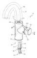
- FIG. 1is a perspective view of an illustrative embodiment faucet of the present disclosure
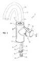
- FIG. 2is an exploded perspective view of the faucet of FIG. 1 ;
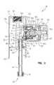
- FIG. 3is a cross-sectional view of the faucet of FIG. 1 , taken along line 3 - 3 of FIG. 1 ;
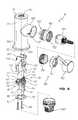
- FIG. 4is an exploded perspective view of a hub and a valve body of the faucet of FIG. 1 ;
- FIG. 5is a perspective view of another illustrative embodiment faucet of the present disclosure.
- FIG. 6is an exploded perspective view of the faucet of FIG. 5 ;
- FIG. 7is a cross-sectional view of the faucet of FIG. 5 , taken along line 7 - 7 of FIG. 5 ;
- FIG. 8is an exploded perspective view of a hub and a waterway adapter of the faucet of FIG. 5 ;
- FIG. 9is an exploded perspective view of the hub and a valve body of the faucet of FIG. 5 ;
- FIG. 10is a cross-sectional view of the faucet of FIG. 5 , taken along line 10 - 10 of FIG. 5 , shown with the waterway adapter inside the hub;
- FIG. 11is a cross-sectional view similar to FIG. 10 , shown with the waterway adapter removed from the hub.
- faucet 10including spout body 11 (shown in phantom), hub 20 , waterway assembly 30 , waterway adapter 60 , and valve assembly 100 .
- faucet 10receives water from hot and cold water supplies (not shown) and mixes the incoming water to form an outlet stream.
- Faucet 10may be mounted to a sink deck (not shown) or another suitable surface and may deliver the mixed outlet stream into a sink basin (not shown), for example.
- the illustrative hub 20 of faucet 10is a generally hollow component having a vertically disposed body portion 20 a and a horizontally disposed valve portion 20 b extending transversely therefrom.
- Body portion 20 a of hub 20includes an open bottom end 22 that is configured to rest against the sink deck (not shown) or other suitable surface.
- Body portion 20 a of hub 20also includes top end 24 that is configured to mate with spout body 11 ( FIG. 1 ).
- top end 24 of body portion 20 aincludes an internally threaded bore 26 that may be sized to receive and engage an externally threaded spout body 11 , for example, thereby securing spout body 11 onto hub 20 .
- Hub 20may also define one or more internally threaded bores 28 for receiving screws 80 therein, as discussed further below.
- valve portion 20 b of hub 20also includes an open end 29 . As shown in FIG. 2 , open end 22 is longitudinally disposed and open end 29 is laterally disposed at a substantially 90 degree angle from open end 22 .
- Hub 20 of faucetmay be formed of a traditional metallic material, such as zinc or brass. It is also within the scope of the present disclosure that hub 20 may be formed of a non-metallic material, such as a polymer, illustratively a cross-linkable polymer. Suitable non-metallic materials that may be used to construct hub 20 include cross-linkable polyethylene (PEX), polybutylene terephthalate (PBT), polyester, melamine, melamine urea, and melamine phenolic.
- PEXcross-linkable polyethylene
- PBTpolybutylene terephthalate
- polyesterpolyester
- melaminemelamine urea
- melamine phenolicmelamine phenolic
- the illustrative waterway assembly 30 of faucet 10includes hot water inlet tube 12 , cold water inlet tube 14 , and outlet tube 16 .
- Hot and cold water inlet tubes 12 , 14 , of waterway assembly 30may be fluidly coupled to hot and cold water supplies (not shown), respectively, for receiving water into faucet 10 .
- Outlet tube 16 of waterway assembly 30may be fluidly coupled to a spout tube (not shown) for delivering water from faucet 10 .
- Each tube 12 , 14 , 16extends between first end 32 and an opposing second end 34 .
- first end 32 of each tube 12 , 14 , 16extends freely beneath hub 20 .
- First ends 32 of hot and cold water inlet tubes 12 , 14may include conventional fluid couplings, such as nuts 36 , for fluidly coupling hot and cold inlet tubes 12 , 14 , onto the hot and cold water supplies, respectively.
- First end 32 of outlet tube 16may include tip 38 for fluidly coupling outlet tube 16 into spout tube 11 a that extends upwardly through spout body 11 to dispense water from faucet 10 .
- second end 34 of each tube 12 , 14 , 16is received within hub 20 .
- Second end 34 of each tube 12 , 14 , 16may receive a corresponding connector, illustratively nipple 42 , 44 , 46 , therein.
- Each nipple 42 , 44 , 46may include external projections or barbs 48 , as shown in FIG. 3 , for gripping the corresponding tube 12 , 14 , 16 .
- each nipple 42 , 44 , 46may define one or more external, annular grooves 49 for receiving sealing rings (not shown) therein.
- the illustrative waterway assembly 30 of faucet 10also includes a disk-shaped body or collar 50 that surrounds and supports tubes 12 , 14 , 16 , specifically second ends 34 of tubes 12 , 14 , 16 , as shown in FIG. 2 .
- first ends 32 of tubes 12 , 14 , 16hang freely beneath collar 50 and nipples 42 , 44 , 46 , extend above collar 50 .
- Collar 50may define one or more apertures 52 for receiving screws 80 therethrough, as discussed further below.
- waterway assembly 30may be formed of a flexible, non-metallic material, such as a polymer, illustratively a cross-linkable polymer. As such, waterway assembly 30 is illustratively electrically non-conductive. In one illustrative embodiment, substantially the entire waterway assembly 30 (including tubes 12 , 14 , 16 , nipples 42 , 44 , 46 , and collar 50 ) is formed of a polyethylene which is subsequently cross-linked to form cross-linked polyethylene (PEX).
- PEXcross-linked polyethylene
- waterway assembly 30Other suitable materials that may be used to construct waterway assembly 30 include polyethylene (PE) (such as raised temperature resistant polyethylene (PE-RT)), polypropylene (PP) (such as polypropylene random (PPR)), and polybutylene (PB). It is further envisioned that waterway assembly 30 may be constructed of cross-linked polyvinyl chloride (PVCX) using silane free radical initiators, cross-linked polyurethane, or cross-linked propylene (XLPP) using peroxide or silane free radical initiators. It is within the scope of the present disclosure that the polymer material used to construct waterway assembly 30 may include reinforcing members, such as glass fibers.
- PEpolyethylene
- PE-RTraised temperature resistant polyethylene
- PPpolypropylene
- PBpolybutylene
- PVCXcross-linked polyvinyl chloride
- XLPPcross-linked propylene
- the polymer material used to construct waterway assembly 30may include reinforcing members, such as glass fibers.
- Waterway assembly 30may be constructed by the method set forth in International Patent Application No. PCT/US10/25524 to Nelson et al., filed Feb. 26, 2010, entitled “FAUCET MANIFOLD,” the disclosure of which is expressly incorporated by reference herein.
- nipples 42 , 44 , 46are inserted into the corresponding tubes 12 , 14 , 16 , with barbs 48 engaging tubes 12 , 14 , 16 , to resist withdrawal of nipples 42 , 44 , 46 , from the corresponding tubes 12 , 14 , 16 .
- collar 50is formed by overmolding collar 50 around second ends 34 of tubes 12 , 14 , 16 , and nipples 42 , 44 , 46 , located therein. This overmolding step forms a material-to-material bond between collar 50 and tubes 12 , 14 , 16 .
- the assembled waterway assembly 30is optionally cross-linked.
- the illustrative waterway adapter 60 of faucet 10fluidly couples waterway assembly 30 to valve assembly 100 .
- Waterway adapter 60defines hot water inlet channel 62 , cold water inlet channel 64 , and outlet channel 66 .
- channels 62 , 64 , 66are bent or L-shaped to couple the vertically disposed waterway assembly 30 to the horizontally disposed valve assembly 100 .
- each channel 62 , 64 , 66 , of waterway adapter 60is sized to receive a corresponding nipple 42 , 44 , 46 , of waterway assembly 30 .
- Providing seals (not shown) in grooves 49 of nipples 42 , 44 , 46may resist leakage between waterway assembly 30 and waterway adapter 60 .
- waterway adapter 60may be formed of a non-metallic material, such as a polymer.
- waterway adapter 60is formed of a glass fiber reinforced polysulfone, such as Udel® GF-110, which is a registered trademark of Solvay Advanced Polymers of Alpharetta, Ga.
- waterway adapter 60is formed of polyethylene, which may be subsequently cross-linked to form cross-linked polyethylene (PEX).
- waterway adapter 60Other suitable materials that may be used to construct waterway adapter 60 include polyethylene (PE) (such as raised temperature resistant polyethylene (PE-RT)), polypropylene (PP) (such as polypropylene random (PPR)), and polybutylene (PB). It is further envisioned that waterway adapter 60 may be constructed of cross-linked polyvinyl chloride (PVCX) using silane free radical initiators, cross-linked polyurethane, or cross-linked propylene (XLPP) using peroxide or silane free radical initiators. It is within the scope of the present disclosure that the polymer material used to construct waterway adapter 60 may include reinforcing members, such as glass fibers.
- PEpolyethylene
- PE-RTraised temperature resistant polyethylene
- PPpolypropylene
- PBpolybutylene
- PVCXcross-linked polyvinyl chloride
- XLPPcross-linked propylene
- the polymer material used to construct waterway adapter 60may include reinforcing members, such as glass
- waterway adapter 60defines apertures 68 that receive screws 80 therethrough for coupling waterway adapter 60 to waterway assembly 30 and to hub 20 . Also, waterway adapter 60 includes pin holes 70 and externally threaded rim 72 for coupling waterway adapter 60 to valve assembly 100 .
- one or more fasteners, such as screws 80 , and mounting plate 82are provided to secure waterway assembly 30 and waterway adapter 60 within hub 20 .
- mounting plate 82defines corresponding apertures 84 for receiving screws 80 therethrough.
- Faucet 10may be assembled by inserting waterway adapter 60 and waterway assembly 30 upwardly into body portion 20 a of hub 20 through the open first end 22 of hub 20 .
- waterway adapter 60 and waterway assembly 30are both narrower than the open first end 22 of hub 20 so that both components may be inserted upwardly into body portion 20 a of hub 20 through the open first end 22 of hub 20 .
- screws 80When assembled, screws 80 extend through apertures 84 in mounting plate 82 , through apertures 52 in collar 50 , through apertures 68 in waterway adapter 60 , and into internally threaded bores 28 of hub 20 , thereby securing waterway assembly 30 and waterway adapter 60 into body portion 20 a of hub 20 .
- Mounting plate 82also defines central aperture 86 that is sized to accommodate spout tube 11 a ( FIG. 1 ) that extends upwardly from tip 38 of outlet tube 16 , through body portion 20 a of hub 20 , and into spout body 11 ( FIG. 1 ) mounted atop hub 20 to dispense water from faucet 10 .
- spout tube 11 amay extend upwardly through central aperture 86 of mounting plate 82 , alongside collar 50 of waterway assembly 30 , and alongside waterway adapter 60 until reaching spout body 11 mounted atop hub 20 .
- mounting plate 82entirely encloses central aperture 86 .
- mounting plate 82may also be slitted like mounting plate 82 ′ of FIG. 6 to facilitate assembly of mounting plate 82 ′ onto waterway assembly 30 ′, as discussed further below.
- valve assembly 100 of faucet 10includes handle 102 , bonnet 104 , sleeve 106 , valve body 108 , and seal 110 .
- valve assembly 100is supported by valve portion 20 b of hub 20 and is removably coupled to waterway adapter 60 located in body portion 20 a of hub 20 .
- valve assembly 100may be removed from the open end 29 of valve portion 20 b of hub 20 for cleaning or servicing without having to remove waterway adapter 60 from body portion 20 a of hub 20 .
- Sleeve 106 of the illustrative valve assembly 100includes an internally threaded first end 120 and an externally threaded second end 122 .
- Sleeve 106also includes first internal shoulder 124 and second internal shoulder 126 .
- valve body 108is removably coupled to waterway adapter 60 by fitting sleeve 106 over valve body 108 and screwing the internally threaded first end 120 of sleeve 106 onto the externally threaded rim 72 of waterway adapter 60 . As shown in FIG.
- second shoulder 126 of sleeve 106forces valve body 108 against waterway adapter 60 , with first shoulder 124 of sleeve 106 engaging seal 110 to reduce leakage between waterway adapter 60 and sleeve 106 .
- Bonnet 104may then be screwed onto the externally threaded second end 122 of sleeve 106 for receiving handle 102 thereon.
- Valve body 108 of the illustrative valve assembly 100includes lower housing 130 having face seal 131 thereon, lower disc 132 , upper disc 134 , carrier 136 , coupling member 137 , upper housing 138 , and stem 140 .
- both upper disc 134 and lower disc 132are constructed of a ceramic material or another suitable material, such as stainless steel.
- valve body 108also includes hot water inlet port 142 , cold water inlet port 144 , and outlet port 146 .
- hot water inlet port 142 of valve body 108When assembled, hot water inlet port 142 of valve body 108 is arranged in fluid communication with hot water inlet channel 62 of waterway adapter 60 , cold water inlet port 144 of valve body 108 is arranged in fluid communication with cold water inlet channel 64 of waterway adapter 60 , and outlet port 146 of valve body 108 is arranged in fluid communication with outlet channel 66 of waterway adapter 60 .
- Face seal 131 on lower housing 130 of valve body 108may seal against waterway adapter 60 , as shown in FIG. 3 , to resist leakage between the components.
- One or more first locating elementsextend from valve body 108 to assist with coupling valve body 108 to waterway adapter 60 .
- pegs 148extend from lower housing 130 of valve body 108 and into corresponding pin holes 70 of waterway adapter 60 . Positioning each peg 148 of valve body 108 within a corresponding pin hole 70 of waterway adapter 60 may facilitate proper orientation of valve body 108 relative to waterway adapter 60 , and as a result, proper orientation of valve body 108 relative to waterway assembly 30 .
- each peg 148 of valve body 108 within a corresponding pin hole 70 of waterway adapter 60may facilitate proper orientation of tubes 12 , 14 , 16 , and nipples 42 , 44 , 46 , of waterway assembly 30 , channels 62 , 64 , 66 , of waterway adapter 60 , and ports 142 , 144 , 146 , of valve body 108 , respectively. Also, positioning each peg 148 of valve body 108 within a corresponding pin hole 70 of waterway adapter 60 may improve resistance to torque generated between hub 20 , waterway assembly 30 , waterway adapter 60 , and valve assembly 100 .
- the illustrative valve assembly 100may be operated by adjusting handle 102 .
- Adjusting handle 102actuates stem 140 of valve body 108 , which transmits movement of handle 102 to upper disc 134 via carrier 136 .
- upper disc 134is positioned adjacent to lower disc 132 to control the mixing of hot and cold water and the flow rate of water through valve body 108 . Therefore, by adjusting handle 102 and moving upper disc 134 relative to lower disc 132 , a user is able to selectively vary the temperature and flow rate of water supplied to outlet port 146 of valve body 108 via hot and cold water inlet ports 142 , 144 , of valve body 108 .
- adjusting handle 102allows a user to selectively vary the temperature and flow rate of water supplied to outlet tube 16 of waterway assembly 30 from hot and cold water inlet tubes 12 , 14 , of waterway assembly 30 .
- valve assembly 100is of a movable disc variety, it should be appreciated that other types of valve assemblies may be substituted therefor.
- a ball-type mixing valve assemblymay find equal applicability with the present invention.
- hot and cold waterflows from hot and cold water supplies (not shown) to valve assembly 100 of faucet 10 . More particularly, hot water flows from the hot water supply to hot water inlet port 142 of valve assembly 100 via hot water inlet tube 12 of waterway assembly 30 , hot water inlet nipple 42 of waterway assembly 30 , and hot water inlet channel 62 of waterway adapter 60 . Similarly, cold water flows from the cold water supply to cold water inlet port 144 of valve assembly 100 via cold water inlet tube 14 of waterway assembly 30 , cold water inlet nipple 44 of waterway assembly 30 , and cold water inlet channel 64 of waterway adapter 60 . Then, the hot and cold inlet water streams are mixed and redirected in valve assembly 100 . The mixed outlet water stream flows from outlet port 146 of valve assembly 100 , through outlet channel 66 of waterway adapter 60 , through outlet nipple 46 of waterway assembly 30 , and through outlet tube 16 of waterway assembly 30 .
- FIGS. 5-11another illustrative embodiment faucet 10 ′ is shown including spout body 11 ′ (shown in phantom), hub 20 ′, waterway assembly 30 ′, waterway adapter 60 ′, and valve assembly 100 ′.
- Faucet 10 ′ of FIGS. 5-11includes features similar to those of faucet 10 of FIGS. 1-4 , with like reference numerals indicating like elements, except as described below.
- the illustrative hub 20 ′ of faucet 10 ′includes a vertically disposed body portion 20 a ′ and a horizontally disposed valve portion 20 b ′ extending transversely therefrom.
- Body portion 20 a ′ of the illustrative hub 20 ′has an internally threaded and open bottom end 22 ′ that is configured to engage an externally threaded mounting shank 200 ′.
- mounting shank 200 ′extends beneath the sink deck and may receive a bracket (not shown) for securing faucet 10 ′ onto the sink deck.
- valve portion 20 b ′ of the illustrative hub 20 ′may be internally threaded, as discussed further below.
- valve portion 20 b ′ of hub 20 ′also includes an open end 29 ′. As shown in FIG. 7 , open end 22 ′ is longitudinally disposed and open end 29 ′ is laterally disposed at a substantially 90 degree angle from open end 22 ′.
- the illustrative waterway assembly 30 ′ of faucet 10 ′includes a disk-shaped body or collar 50 ′ that surrounds and supports tubes 12 ′, 14 ′, 16 ′.
- Collar 50 ′may define one or more apertures 52 ′ for receiving screws 80 ′ therethrough.
- collar 50 ′may define a central aperture 54 ′ that is sized to accommodate spout tube 11 a ′ ( FIG. 5 ), as discussed further below.
- the illustrative waterway adapter 60 ′ of faucet 10 ′includes rear protrusion 260 ′ having an upper shoulder 262 ′.
- Waterway adapter 60 ′may also include internally threaded bores 264 ′, as discussed further below.
- waterway adapter 60 ′is a generally hollow component that defines opening 266 ′ therethrough. Opening 266 ′ extends vertically through waterway adapter 60 ′ and is bordered on one side by channels 62 ′, 64 ′, 66 ′, and on the opposite side by rear protrusion 260 ′.
- one or more fastenerssuch as screws 80 ′, and mounting plate 82 ′ are provided to secure waterway assembly 30 ′ to waterway adapter 60 ′.
- mounting plate 82 ′defines corresponding apertures 84 ′ for receiving screws 80 ′ therethrough.
- screws 80 ′extend through apertures 84 ′ in mounting plate 82 ′, through apertures 52 ′ in collar 50 ′, and into internally threaded bores 264 ′ of waterway adapter 60 ′, thereby securing waterway assembly 30 ′ to waterway adapter 60 ′.
- Mounting plate 82 ′also defines central aperture 86 ′ that is sized to accommodate a spout tube 11 a ′ ( FIG. 5 ) that extends upwardly from tip 38 ′ of outlet tube 16 ′, through body portion 20 a ′ of hub 20 ′, and into spout body 11 ′ ( FIG. 5 ) mounted atop hub 20 ′ to dispense water from faucet 10 ′.
- spout tube 11 a ′may extend upwardly through central aperture 86 ′ of mounting plate 82 ′, through central aperture 54 ′ of collar 50 ′, and through opening 266 ′ in waterway adapter 60 ′ until reaching spout body 11 ′ mounted atop hub 20 ′.
- mounting plate 82 ′may be slit along central aperture 86 ′ to facilitate assembly of mounting plate 82 ′ onto waterway assembly 30 ′.
- tubes 12 ′, 14 ′, 16 ′, of waterway assembly 30 ′may be snapped into the slitted mounting plate 82 ′.
- mounting plate 82 ′may entirely enclose central aperture 86 ′, like mounting plate 82 of FIG. 2 .
- the illustrative valve assembly 100 ′ of faucet 10 ′includes handle 102 ′, bonnet 104 ′, nut 105 ′, sleeve 106 ′, and valve body 108 ′.
- Sleeve 106 ′ of the illustrative valve assembly 100 ′includes an externally threaded first end 120 ′ and an internally threaded second end 122 ′.
- Nut 105 ′ of the illustrative valve assembly 100 ′is externally threaded and configured to fit within the internally threaded second end 122 ′ of sleeve 106 ′.
- hub 20 ′ of the illustrative faucet 10 ′includes internal rails 220 ′ that are sized to receive and center rear protrusion 260 ′ of waterway adapter 60 ′ therebetween.
- Each rail 220 ′ of hub 20 ′includes a downward-facing stop 222 ′ that is configured to abut a corresponding upper shoulder 262 ′ of waterway adapter 60 ′.
- Faucet 10 ′may be assembled by inserting waterway assembly 30 ′ and waterway adapter 60 ′ upwardly into body portion 20 a ′ of hub 20 ′ through the open first end 22 ′ of hub 20 ′. As shown in FIG.
- waterway adapter 60 ′ and waterway assembly 30 ′are both narrower than the open first end 22 ′ of hub 20 ′ so that both components may be inserted upwardly into body portion 20 a ′ of hub 20 ′ through the open first end 22 ′ of hub 20 ′.
- upper shoulder 262 ′ of waterway adapter 60 ′abuts stop 222 ′ of hub 20 ′, as shown in FIG. 7 , the installer knows that waterway adapter 60 ′ is properly positioned within body portion 20 a ′ of hub 20 ′ to align with valve assembly 100 ′, both horizontally and vertically.
- sleeve 106 ′may be screwed into valve portion 20 b ′ of hub 20 ′ such that first end 120 ′ of sleeve 106 ′ forces waterway adapter 60 ′ into contact with rails 220 ′ of hub 20 ′, as shown in FIG. 10 .
- waterway adapter 60 ′ and waterway assembly 30 ′ coupled theretomay be frictionally retained within hub 20 ′ and may resist falling through open end 22 ′ of hub 20 ′ under gravitational force.
- valve assembly 100 ′is supported by valve portion 20 b ′ of hub 20 ′ and is removably coupled to waterway adapter 60 ′ located in body portion 20 a ′ of hub 20 ′.
- valve assembly 100 ′may be removed from the open end 29 ′ of valve portion 20 b ′ of hub 20 ′ for cleaning or servicing without having to remove waterway adapter 60 ′ from body portion 20 a ′ of hub 20 ′.
- Valve body 108 ′may be removably coupled to waterway adapter 60 ′ by fitting nut 105 ′ over valve body 108 ′, as shown in FIG. 7 .
- the externally threaded nut 105 ′may be screwed into the internally threaded second end 122 ′ of sleeve 106 ′.
- Nut 105 ′may force valve body 108 ′ tightly against waterway adapter 60 ′.
- Bonnet 104 ′may then be screwed onto the externally threaded nut 105 ′ for receiving handle 102 ′ thereon.
Landscapes
- Engineering & Computer Science (AREA)
- General Engineering & Computer Science (AREA)
- Mechanical Engineering (AREA)
- Health & Medical Sciences (AREA)
- Life Sciences & Earth Sciences (AREA)
- Hydrology & Water Resources (AREA)
- Public Health (AREA)
- Water Supply & Treatment (AREA)
- Power Engineering (AREA)
- Physics & Mathematics (AREA)
- General Physics & Mathematics (AREA)
- Automation & Control Theory (AREA)
- Valve Housings (AREA)
- Details Of Reciprocating Pumps (AREA)
- Loading And Unloading Of Fuel Tanks Or Ships (AREA)
- Lift Valve (AREA)
Abstract
Description
Claims (13)
Priority Applications (7)
| Application Number | Priority Date | Filing Date | Title |
|---|---|---|---|
| US12/854,541US8453669B2 (en) | 2010-07-21 | 2010-08-11 | Waterway adapter |
| US13/091,865US8739813B2 (en) | 2010-07-21 | 2011-04-21 | Waterway for a single supply faucet |
| CA2805719ACA2805719C (en) | 2010-07-21 | 2011-07-20 | Waterway adapter |
| PCT/US2011/044612WO2012012487A2 (en) | 2010-07-21 | 2011-07-20 | Waterway adapter |
| CN201510087899.XACN104613195B (en) | 2010-07-21 | 2011-07-20 | Waterway adapter |
| CN201180035669.9ACN103003604B (en) | 2010-07-21 | 2011-07-20 | water pipe adapter |
| US13/793,468US8944093B2 (en) | 2010-07-21 | 2013-03-11 | Waterway adapter |
Applications Claiming Priority (2)
| Application Number | Priority Date | Filing Date | Title |
|---|---|---|---|
| US36641010P | 2010-07-21 | 2010-07-21 | |
| US12/854,541US8453669B2 (en) | 2010-07-21 | 2010-08-11 | Waterway adapter |
Related Child Applications (2)
| Application Number | Title | Priority Date | Filing Date |
|---|---|---|---|
| US13/091,865Continuation-In-PartUS8739813B2 (en) | 2010-07-21 | 2011-04-21 | Waterway for a single supply faucet |
| US13/793,468ContinuationUS8944093B2 (en) | 2010-07-21 | 2013-03-11 | Waterway adapter |
Publications (2)
| Publication Number | Publication Date |
|---|---|
| US20120018009A1 US20120018009A1 (en) | 2012-01-26 |
| US8453669B2true US8453669B2 (en) | 2013-06-04 |
Family
ID=45492571
Family Applications (2)
| Application Number | Title | Priority Date | Filing Date |
|---|---|---|---|
| US12/854,541Active2031-04-21US8453669B2 (en) | 2010-07-21 | 2010-08-11 | Waterway adapter |
| US13/793,468ActiveUS8944093B2 (en) | 2010-07-21 | 2013-03-11 | Waterway adapter |
Family Applications After (1)
| Application Number | Title | Priority Date | Filing Date |
|---|---|---|---|
| US13/793,468ActiveUS8944093B2 (en) | 2010-07-21 | 2013-03-11 | Waterway adapter |
Country Status (4)
| Country | Link |
|---|---|
| US (2) | US8453669B2 (en) |
| CN (2) | CN104613195B (en) |
| CA (1) | CA2805719C (en) |
| WO (1) | WO2012012487A2 (en) |
Cited By (20)
| Publication number | Priority date | Publication date | Assignee | Title |
|---|---|---|---|---|
| US20130056664A1 (en)* | 2011-09-07 | 2013-03-07 | Chun-Chieh Huang | Controlling Seat Structure for a Faucet |
| US20130186482A1 (en)* | 2010-07-21 | 2013-07-25 | Masco Corporation Of Indiana | Waterway adapter |
| US9057184B2 (en) | 2011-10-19 | 2015-06-16 | Delta Faucet Company | Insulator base for electronic faucet |
| US9074357B2 (en) | 2011-04-25 | 2015-07-07 | Delta Faucet Company | Mounting bracket for electronic kitchen faucet |
| US20160047112A1 (en)* | 2014-08-15 | 2016-02-18 | Xiamen Runner Industrial Corporation | Inner Water Pipe Assembly For Faucet |
| US9333698B2 (en) | 2013-03-15 | 2016-05-10 | Delta Faucet Company | Faucet base ring |
| US20180094412A1 (en)* | 2016-10-04 | 2018-04-05 | Hansgrohe Se | Faucet column and free-standing sanitary fitting system |
| US9958086B2 (en) | 2016-01-26 | 2018-05-01 | Kohler Co. | Faucet assembly |
| US10006190B1 (en) | 2016-12-02 | 2018-06-26 | Moen Incorporated | Pullout faucet with mounting system |
| US20190017624A1 (en)* | 2017-07-12 | 2019-01-17 | Masco Canada Limited | Low profile faucet handle assembly for a roman tub |
| US20190085993A1 (en)* | 2017-09-15 | 2019-03-21 | Delta Faucet Company | Waterway assembly for a faucet |
| US10240325B1 (en)* | 2017-09-28 | 2019-03-26 | Xiamen Lota International Co., Ltd. | Mounting structure for faucet body and shaft |
| US20190113144A1 (en)* | 2017-10-13 | 2019-04-18 | Lily Gabriel | Valve Assembly |
| US10281049B2 (en) | 2016-01-26 | 2019-05-07 | Kohler Co. | Valve assembly |
| EP3591127A1 (en)* | 2018-07-04 | 2020-01-08 | Villeroy & Boch Gustavsberg AB | A fluid distribution assembly for a faucet and a faucet |
| US11215289B1 (en)* | 2021-04-08 | 2022-01-04 | Chunhe Qiu | Valve core assembly |
| US20220325809A1 (en)* | 2021-04-08 | 2022-10-13 | Chunhe Qiu | Valve core assembly |
| US20220325808A1 (en)* | 2021-04-08 | 2022-10-13 | Chunhe Qiu | Valve core assembly |
| US11614174B1 (en)* | 2022-01-03 | 2023-03-28 | Chunhe Qiu | Fluid channel structure, valve core assembly and tap |
| US11788263B2 (en)* | 2017-10-13 | 2023-10-17 | Lily Herron | Valve enclosure |
Families Citing this family (27)
| Publication number | Priority date | Publication date | Assignee | Title |
|---|---|---|---|---|
| US8739813B2 (en) | 2010-07-21 | 2014-06-03 | Masco Corporation Of Indiana | Waterway for a single supply faucet |
| US8631816B2 (en)* | 2012-01-19 | 2014-01-21 | Da Yuan Sheng Industrial Co., Ltd | Faucet structure |
| US8584696B2 (en)* | 2012-01-19 | 2013-11-19 | Da Yuan Sheng Industrial Co. Ltd. | Water control structure of faucet |
| WO2013138594A1 (en)* | 2012-03-14 | 2013-09-19 | Liqui-Box Corporation | An adaptor for use with a valve fitment for dispensing fluids |
| DE102012212302C5 (en)* | 2012-07-13 | 2019-11-21 | Hansgrohe Se | plumbing fixture |
| DE102012212306A1 (en)* | 2012-07-13 | 2014-01-16 | Hansgrohe Se | plumbing fixture |
| CA2882762C (en)* | 2012-09-06 | 2018-01-16 | Masco Corporation Of Indianna | Faucet waterway |
| WO2014045281A1 (en)* | 2012-09-24 | 2014-03-27 | Ergonomix Concept E.G Ltd | Nonlinear transmission rate between operating handle and operated mechanism |
| US9206917B2 (en)* | 2014-01-14 | 2015-12-08 | Hsue Sam Enterprise Co. Ltd. | Positioning structure of water guiding duct in faucet valve base |
| US9879407B2 (en)* | 2014-12-12 | 2018-01-30 | Kohler Co. | Faucet handle fitting |
| DE102015002257A1 (en)* | 2015-02-25 | 2016-08-25 | Grohe Ag | Sanitary fitting with a hose connection fastened with a clamp |
| US9670653B2 (en)* | 2015-06-22 | 2017-06-06 | Lianhua Mao | Cartridge type valve core structure of water tap |
| ITUB20161165A1 (en)* | 2016-02-29 | 2017-08-29 | Ib Rubinetterie S P A | Single lever mixer mixer group |
| WO2018099003A1 (en)* | 2016-11-30 | 2018-06-07 | 佛山市顺德区美的饮水机制造有限公司 | Water spigot |
| US10184575B2 (en) | 2017-01-11 | 2019-01-22 | Kohler Co. | Faucet with multi-directional controls |
| CN107091341A (en)* | 2017-05-23 | 2017-08-25 | 开平市圣柏卫浴有限公司 | A kind of tap of Fast Installation |
| US10450729B2 (en)* | 2017-09-20 | 2019-10-22 | Globe Union Industrial Corp. | Pull-out faucet |
| CN107542955A (en)* | 2017-09-28 | 2018-01-05 | 路达(厦门)工业有限公司 | A kind of fixed structure of faucet body and stud shaft |
| US10234049B1 (en)* | 2017-10-20 | 2019-03-19 | Globe Union Industrial Corp. | Pull-out faucet |
| JP6924133B2 (en)* | 2017-12-26 | 2021-08-25 | パナソニックIpマネジメント株式会社 | Water faucet |
| CA3121502C (en)* | 2020-06-11 | 2023-12-19 | Delta Faucet Company | Manifold with insert for waterway assembly |
| JP7427165B2 (en)* | 2020-07-31 | 2024-02-05 | Toto株式会社 | Faucet device |
| US11365817B2 (en)* | 2020-09-10 | 2022-06-21 | Kuching International Ltd. | High flow valve seat for water control valve |
| USD954906S1 (en)* | 2020-12-08 | 2022-06-14 | Delta Faucet Company | Faucet |
| KR102305480B1 (en)* | 2021-01-28 | 2021-09-27 | 김이섭 | Multipurpose faucet |
| DE102022106835A1 (en) | 2022-03-23 | 2023-09-28 | Grohe Ag | Sanitary fitting |
| EP4530411A1 (en)* | 2024-08-09 | 2025-04-02 | Neoperl GmbH | Cartridge adapter, cartridge adapter set, use of a cartridge adapter and sanitary fitting |
Citations (20)
| Publication number | Priority date | Publication date | Assignee | Title |
|---|---|---|---|---|
| US4043359A (en) | 1976-05-05 | 1977-08-23 | Masco Corporation Of Indiana | Water faucet |
| US6185760B1 (en) | 1997-03-12 | 2001-02-13 | Park Yeon-Soo | Liquid flow control tap with inexhaustible energy-operated valve |
| US6289531B1 (en)* | 1998-12-08 | 2001-09-18 | Friedrich Grohe Ag & Co. Kg | Faucet valve fixture |
| US20040010848A1 (en)* | 2002-07-16 | 2004-01-22 | Esche John C. | Pull-out faucet |
| US20040221385A1 (en) | 2003-05-09 | 2004-11-11 | Su Chorng Chyi | Stainless steel faucet |
| US6868564B2 (en) | 2000-03-09 | 2005-03-22 | Hansgrohe Ag | Sanitary fitting, particularly kitchen mixer |
| US20060151034A1 (en) | 2003-03-19 | 2006-07-13 | Clack Corporation | Faucet |
| US7159252B2 (en) | 2001-11-09 | 2007-01-09 | Today's Gear, Inc. | Folding sink |
| US7182100B2 (en) | 2004-03-03 | 2007-02-27 | Masco Corporation Of Indiana | Retrofittable mixing valve and method of assembly |
| US20070271695A1 (en)* | 2006-05-26 | 2007-11-29 | Kurt Judson Thomas | Faucet including a molded waterway assembly |
| US20080276367A1 (en) | 2007-05-07 | 2008-11-13 | Bares William R | Faucet With Spray Head |
| US7556061B2 (en) | 2005-11-29 | 2009-07-07 | Toto Ltd. | Mixing faucet assembly |
| US20090242058A1 (en) | 2008-03-26 | 2009-10-01 | Kohler Co. | Faucet with Accessible Waterway Assembly |
| US20100006166A1 (en) | 2008-07-10 | 2010-01-14 | Jui-Chien Chen | Drinking faucet with monitoring device |
| US20100127202A1 (en) | 2008-11-26 | 2010-05-27 | Moen Incorporated | Valve body |
| WO2010099397A1 (en) | 2009-02-27 | 2010-09-02 | Masco Corporation Of Indiana | Faucet manifold |
| US20110016625A1 (en) | 2007-01-31 | 2011-01-27 | Garry Robin Marty | Mixing valve including a molded waterway assembly |
| US7980268B2 (en) | 2006-07-28 | 2011-07-19 | Masco Corporation Of Indiana | Mixing valve |
| US20120018020A1 (en) | 2010-07-21 | 2012-01-26 | Moore Jeffrey L | Waterway for a single supply faucet |
| US8240326B2 (en) | 2009-06-30 | 2012-08-14 | Moen Incorporated | Faucet with assembly and retention features |
Family Cites Families (12)
| Publication number | Priority date | Publication date | Assignee | Title |
|---|---|---|---|---|
| DE59400560D1 (en)* | 1993-04-08 | 1996-10-02 | Ideal Standard | SANITARY WATER VALVE |
| DE4415797A1 (en) | 1994-05-05 | 1995-11-09 | Grohe Armaturen Friedrich | Water tap |
| DE19810699A1 (en) | 1998-03-12 | 1999-09-16 | Grohe Armaturen Friedrich | Water tap |
| IT1299801B1 (en) | 1998-05-29 | 2000-04-04 | Paini S P A Rubinetterie | SINGLE-LEVER MIXER TAP DEVICE |
| CN100475581C (en)* | 1999-08-24 | 2009-04-08 | 哈尔德克斯制动器公司 | height control valve |
| DE19956401A1 (en) | 1999-11-24 | 2001-05-31 | Grohe Armaturen Friedrich | Water tap |
| BR0206040A (en)* | 2001-10-01 | 2003-09-09 | Newfrey Llc | Single Control Roman Tub Faucet |
| DE102004049736B4 (en)* | 2004-10-13 | 2009-09-17 | Hansa Metallwerke Ag | Sanitary washbasin faucet |
| US20060101576A1 (en)* | 2004-11-18 | 2006-05-18 | Masco Corporation Of Indiana | Faucet quick install nut |
| CN2823720Y (en)* | 2005-10-17 | 2006-10-04 | 邹建仁 | Non-metal water tap |
| US7896025B2 (en)* | 2007-06-29 | 2011-03-01 | Masco Corporation Of Indiana | Valve body |
| US8453669B2 (en)* | 2010-07-21 | 2013-06-04 | Masco Corporation Of Indiana | Waterway adapter |
- 2010
- 2010-08-11USUS12/854,541patent/US8453669B2/enactiveActive
- 2011
- 2011-07-20CNCN201510087899.XApatent/CN104613195B/enactiveActive
- 2011-07-20CNCN201180035669.9Apatent/CN103003604B/enactiveActive
- 2011-07-20CACA2805719Apatent/CA2805719C/enactiveActive
- 2011-07-20WOPCT/US2011/044612patent/WO2012012487A2/enactiveApplication Filing
- 2013
- 2013-03-11USUS13/793,468patent/US8944093B2/enactiveActive
Patent Citations (24)
| Publication number | Priority date | Publication date | Assignee | Title |
|---|---|---|---|---|
| US4043359A (en) | 1976-05-05 | 1977-08-23 | Masco Corporation Of Indiana | Water faucet |
| US6185760B1 (en) | 1997-03-12 | 2001-02-13 | Park Yeon-Soo | Liquid flow control tap with inexhaustible energy-operated valve |
| US6289531B1 (en)* | 1998-12-08 | 2001-09-18 | Friedrich Grohe Ag & Co. Kg | Faucet valve fixture |
| US6868564B2 (en) | 2000-03-09 | 2005-03-22 | Hansgrohe Ag | Sanitary fitting, particularly kitchen mixer |
| US7159252B2 (en) | 2001-11-09 | 2007-01-09 | Today's Gear, Inc. | Folding sink |
| US20040010848A1 (en)* | 2002-07-16 | 2004-01-22 | Esche John C. | Pull-out faucet |
| US20060151034A1 (en) | 2003-03-19 | 2006-07-13 | Clack Corporation | Faucet |
| US20040221385A1 (en) | 2003-05-09 | 2004-11-11 | Su Chorng Chyi | Stainless steel faucet |
| US7182100B2 (en) | 2004-03-03 | 2007-02-27 | Masco Corporation Of Indiana | Retrofittable mixing valve and method of assembly |
| US7556061B2 (en) | 2005-11-29 | 2009-07-07 | Toto Ltd. | Mixing faucet assembly |
| US20090020177A1 (en) | 2006-05-26 | 2009-01-22 | Masco Corporation Of Indiana | Valve mounting assembly |
| US20100313979A1 (en) | 2006-05-26 | 2010-12-16 | Kurt Judson Thomas | Faucet Including a Molded Waterway Assembly |
| WO2007139605A1 (en) | 2006-05-26 | 2007-12-06 | Masco Corporation Of Indiana | Faucet including a molded waterway assembly |
| US20070271695A1 (en)* | 2006-05-26 | 2007-11-29 | Kurt Judson Thomas | Faucet including a molded waterway assembly |
| US7980268B2 (en) | 2006-07-28 | 2011-07-19 | Masco Corporation Of Indiana | Mixing valve |
| US20110016625A1 (en) | 2007-01-31 | 2011-01-27 | Garry Robin Marty | Mixing valve including a molded waterway assembly |
| US20080276367A1 (en) | 2007-05-07 | 2008-11-13 | Bares William R | Faucet With Spray Head |
| US20090242058A1 (en) | 2008-03-26 | 2009-10-01 | Kohler Co. | Faucet with Accessible Waterway Assembly |
| US20100006166A1 (en) | 2008-07-10 | 2010-01-14 | Jui-Chien Chen | Drinking faucet with monitoring device |
| US20100127202A1 (en) | 2008-11-26 | 2010-05-27 | Moen Incorporated | Valve body |
| WO2010099397A1 (en) | 2009-02-27 | 2010-09-02 | Masco Corporation Of Indiana | Faucet manifold |
| US20110297248A1 (en) | 2009-02-27 | 2011-12-08 | Mercury Plastics, Inc. | Faucet manifold |
| US8240326B2 (en) | 2009-06-30 | 2012-08-14 | Moen Incorporated | Faucet with assembly and retention features |
| US20120018020A1 (en) | 2010-07-21 | 2012-01-26 | Moore Jeffrey L | Waterway for a single supply faucet |
Non-Patent Citations (5)
| Title |
|---|
| International Searching Authority, International Search Report and Written Opinion for International Application No. PCT/US2011/044612, mailed Jan. 9, 2012, 9 pages. |
| MOEN Incorporated, Illustrated Parts for Single-Handle Kitchen Faucet, Models 7100, 7100CSL, 7106, and 7106CSL, 3 pages, Mar. 2010. |
| MOEN Incorporated, Instruction pamphlet for One-Handle Kitchen Faucet, Models 7100 and 7106, INS1632A, 6 pages, May 2008. |
| MOEN Incorporated, Specifications for Single-Handle Single-Hole Mount High Arc Kitchen Faucet, Models 7100 and 7106, 2 pages, Aug. 2009. |
| MOEN One-Handle Kitchen Faucet Model 7100, (shown with faucet body disassembled), 6 pages, available on or before May 16, 2010. |
Cited By (28)
| Publication number | Priority date | Publication date | Assignee | Title |
|---|---|---|---|---|
| US20130186482A1 (en)* | 2010-07-21 | 2013-07-25 | Masco Corporation Of Indiana | Waterway adapter |
| US8944093B2 (en)* | 2010-07-21 | 2015-02-03 | Masco Corporation Of Indiana | Waterway adapter |
| US9074357B2 (en) | 2011-04-25 | 2015-07-07 | Delta Faucet Company | Mounting bracket for electronic kitchen faucet |
| US8733396B2 (en)* | 2011-09-07 | 2014-05-27 | Chun-Chieh Huang | Controlling seat structure for a faucet |
| US20130056664A1 (en)* | 2011-09-07 | 2013-03-07 | Chun-Chieh Huang | Controlling Seat Structure for a Faucet |
| US9057184B2 (en) | 2011-10-19 | 2015-06-16 | Delta Faucet Company | Insulator base for electronic faucet |
| US9333698B2 (en) | 2013-03-15 | 2016-05-10 | Delta Faucet Company | Faucet base ring |
| US9476187B2 (en)* | 2014-08-15 | 2016-10-25 | Xiamen Runner Industrial Corporation | Inner water pipe assembly for faucet |
| US20160047112A1 (en)* | 2014-08-15 | 2016-02-18 | Xiamen Runner Industrial Corporation | Inner Water Pipe Assembly For Faucet |
| US9958086B2 (en) | 2016-01-26 | 2018-05-01 | Kohler Co. | Faucet assembly |
| US11231116B2 (en) | 2016-01-26 | 2022-01-25 | Kohler Co. | Valve assembly |
| US10281049B2 (en) | 2016-01-26 | 2019-05-07 | Kohler Co. | Valve assembly |
| US20180094412A1 (en)* | 2016-10-04 | 2018-04-05 | Hansgrohe Se | Faucet column and free-standing sanitary fitting system |
| US10577781B2 (en)* | 2016-10-04 | 2020-03-03 | Hansgrohe Se | Faucet column and free-standing sanitary fitting system |
| US10858812B2 (en) | 2016-12-02 | 2020-12-08 | Fb Global Plumbing Group Llc | Pullout faucet with mounting system |
| US10006190B1 (en) | 2016-12-02 | 2018-06-26 | Moen Incorporated | Pullout faucet with mounting system |
| US20190017624A1 (en)* | 2017-07-12 | 2019-01-17 | Masco Canada Limited | Low profile faucet handle assembly for a roman tub |
| US10935157B2 (en)* | 2017-07-12 | 2021-03-02 | Masco Canada Limited | Low profile faucet handle assembly for a roman tub |
| US20190085993A1 (en)* | 2017-09-15 | 2019-03-21 | Delta Faucet Company | Waterway assembly for a faucet |
| US10240325B1 (en)* | 2017-09-28 | 2019-03-26 | Xiamen Lota International Co., Ltd. | Mounting structure for faucet body and shaft |
| US11187331B2 (en)* | 2017-10-13 | 2021-11-30 | Lily Herron | Valve assembly |
| US20190113144A1 (en)* | 2017-10-13 | 2019-04-18 | Lily Gabriel | Valve Assembly |
| US11788263B2 (en)* | 2017-10-13 | 2023-10-17 | Lily Herron | Valve enclosure |
| EP3591127A1 (en)* | 2018-07-04 | 2020-01-08 | Villeroy & Boch Gustavsberg AB | A fluid distribution assembly for a faucet and a faucet |
| US11215289B1 (en)* | 2021-04-08 | 2022-01-04 | Chunhe Qiu | Valve core assembly |
| US20220325809A1 (en)* | 2021-04-08 | 2022-10-13 | Chunhe Qiu | Valve core assembly |
| US20220325808A1 (en)* | 2021-04-08 | 2022-10-13 | Chunhe Qiu | Valve core assembly |
| US11614174B1 (en)* | 2022-01-03 | 2023-03-28 | Chunhe Qiu | Fluid channel structure, valve core assembly and tap |
Also Published As
| Publication number | Publication date |
|---|---|
| CN104613195B (en) | 2017-06-23 |
| WO2012012487A2 (en) | 2012-01-26 |
| US20130186482A1 (en) | 2013-07-25 |
| WO2012012487A3 (en) | 2012-03-15 |
| CA2805719A1 (en) | 2012-01-26 |
| CA2805719C (en) | 2015-10-13 |
| CN103003604A (en) | 2013-03-27 |
| US8944093B2 (en) | 2015-02-03 |
| CN103003604B (en) | 2015-03-18 |
| US20120018009A1 (en) | 2012-01-26 |
| CN104613195A (en) | 2015-05-13 |
Similar Documents
| Publication | Publication Date | Title |
|---|---|---|
| US8453669B2 (en) | Waterway adapter | |
| US8739813B2 (en) | Waterway for a single supply faucet | |
| US8689818B2 (en) | Widespread faucet | |
| US7806141B2 (en) | Mixing valve including a molded waterway assembly | |
| US20110297248A1 (en) | Faucet manifold | |
| US9951880B2 (en) | Faucet including a molded waterway assembly | |
| US8991425B2 (en) | Waterway assembly including an overmolded support plate | |
| US9611945B2 (en) | Faucet waterway | |
| US20130192686A1 (en) | Fluid Delivery Assembly (1-In, Combined with Centering Stop) | |
| US20110079307A1 (en) | Centerset Faucet With Mountable Spout | |
| CA2770310C (en) | Waterway for a single supply faucet |
Legal Events
| Date | Code | Title | Description |
|---|---|---|---|
| AS | Assignment | Owner name:MASCO CORPORATION OF INDIANA, INDIANA Free format text:ASSIGNMENT OF ASSIGNORS INTEREST;ASSIGNORS:VEROS, MICHAEL J.;SAILORS, TIMOTHY J.;NELSON, ALFRED C.;AND OTHERS;SIGNING DATES FROM 20100805 TO 20100809;REEL/FRAME:024824/0549 | |
| AS | Assignment | Owner name:MERCURY PLASTICS, INC., OHIO Free format text:CONFIRMATORY ASSIGNMENT;ASSIGNOR:MASCO CORPORATION OF INDIANA D/B/A DELTA FAUCET COMPANY;REEL/FRAME:027774/0736 Effective date:20120207 | |
| STCF | Information on status: patent grant | Free format text:PATENTED CASE | |
| AS | Assignment | Owner name:DELTA FAUCET COMPANY, INDIANA Free format text:ASSIGNMENT OF ASSIGNORS INTEREST;ASSIGNOR:MASCO CORPORATION OF INDIANA;REEL/FRAME:035168/0845 Effective date:20150219 | |
| FPAY | Fee payment | Year of fee payment:4 | |
| AS | Assignment | Owner name:GOLDEN EAGLE ACQUISITION LLC, MICHIGAN Free format text:ASSIGNMENT OF ASSIGNORS INTEREST;ASSIGNORS:MERCURY PLASTICS, INC.;NEO BEAM ALLIANCE, LIMITED;WILLIAM ROWLEY;REEL/FRAME:044895/0682 Effective date:20171201 | |
| AS | Assignment | Owner name:MERCURY PLASTICS LLC, OHIO Free format text:CHANGE OF NAME;ASSIGNOR:GOLDEN EAGLE ACQUISITION LLC;REEL/FRAME:045001/0256 Effective date:20171201 | |
| MAFP | Maintenance fee payment | Free format text:PAYMENT OF MAINTENANCE FEE, 8TH YEAR, LARGE ENTITY (ORIGINAL EVENT CODE: M1552); ENTITY STATUS OF PATENT OWNER: LARGE ENTITY Year of fee payment:8 | |
| MAFP | Maintenance fee payment | Free format text:PAYMENT OF MAINTENANCE FEE, 12TH YEAR, LARGE ENTITY (ORIGINAL EVENT CODE: M1553); ENTITY STATUS OF PATENT OWNER: LARGE ENTITY Year of fee payment:12 |