US8452516B1 - Variable vane scheduling based on flight conditions for inclement weather - Google Patents
Variable vane scheduling based on flight conditions for inclement weatherDownload PDFInfo
- Publication number
- US8452516B1 US8452516B1US13/446,326US201213446326AUS8452516B1US 8452516 B1US8452516 B1US 8452516B1US 201213446326 AUS201213446326 AUS 201213446326AUS 8452516 B1US8452516 B1US 8452516B1
- Authority
- US
- United States
- Prior art keywords
- gas turbine
- turbine engine
- recited
- flight condition
- programmed
- Prior art date
- Legal status (The legal status is an assumption and is not a legal conclusion. Google has not performed a legal analysis and makes no representation as to the accuracy of the status listed.)
- Active
Links
Images


Classifications
- B—PERFORMING OPERATIONS; TRANSPORTING
- B64—AIRCRAFT; AVIATION; COSMONAUTICS
- B64D—EQUIPMENT FOR FITTING IN OR TO AIRCRAFT; FLIGHT SUITS; PARACHUTES; ARRANGEMENT OR MOUNTING OF POWER PLANTS OR PROPULSION TRANSMISSIONS IN AIRCRAFT
- B64D45/00—Aircraft indicators or protectors not otherwise provided for
- F—MECHANICAL ENGINEERING; LIGHTING; HEATING; WEAPONS; BLASTING
- F01—MACHINES OR ENGINES IN GENERAL; ENGINE PLANTS IN GENERAL; STEAM ENGINES
- F01D—NON-POSITIVE DISPLACEMENT MACHINES OR ENGINES, e.g. STEAM TURBINES
- F01D17/00—Regulating or controlling by varying flow
- F01D17/10—Final actuators
- F01D17/12—Final actuators arranged in stator parts
- F01D17/14—Final actuators arranged in stator parts varying effective cross-sectional area of nozzles or guide conduits
- F01D17/16—Final actuators arranged in stator parts varying effective cross-sectional area of nozzles or guide conduits by means of nozzle vanes
- F01D17/162—Final actuators arranged in stator parts varying effective cross-sectional area of nozzles or guide conduits by means of nozzle vanes for axial flow, i.e. the vanes turning around axes which are essentially perpendicular to the rotor centre line
- F—MECHANICAL ENGINEERING; LIGHTING; HEATING; WEAPONS; BLASTING
- F02—COMBUSTION ENGINES; HOT-GAS OR COMBUSTION-PRODUCT ENGINE PLANTS
- F02C—GAS-TURBINE PLANTS; AIR INTAKES FOR JET-PROPULSION PLANTS; CONTROLLING FUEL SUPPLY IN AIR-BREATHING JET-PROPULSION PLANTS
- F02C7/00—Features, components parts, details or accessories, not provided for in, or of interest apart form groups F02C1/00 - F02C6/00; Air intakes for jet-propulsion plants
- F02C7/04—Air intakes for gas-turbine plants or jet-propulsion plants
- F02C7/05—Air intakes for gas-turbine plants or jet-propulsion plants having provisions for obviating the penetration of damaging objects or particles
- F—MECHANICAL ENGINEERING; LIGHTING; HEATING; WEAPONS; BLASTING
- F02—COMBUSTION ENGINES; HOT-GAS OR COMBUSTION-PRODUCT ENGINE PLANTS
- F02C—GAS-TURBINE PLANTS; AIR INTAKES FOR JET-PROPULSION PLANTS; CONTROLLING FUEL SUPPLY IN AIR-BREATHING JET-PROPULSION PLANTS
- F02C9/00—Controlling gas-turbine plants; Controlling fuel supply in air- breathing jet-propulsion plants
- F02C9/16—Control of working fluid flow
- F02C9/20—Control of working fluid flow by throttling; by adjusting vanes
- F—MECHANICAL ENGINEERING; LIGHTING; HEATING; WEAPONS; BLASTING
- F04—POSITIVE - DISPLACEMENT MACHINES FOR LIQUIDS; PUMPS FOR LIQUIDS OR ELASTIC FLUIDS
- F04D—NON-POSITIVE-DISPLACEMENT PUMPS
- F04D27/00—Control, e.g. regulation, of pumps, pumping installations or pumping systems specially adapted for elastic fluids
- F04D27/02—Surge control
- F04D27/0292—Stop safety or alarm devices, e.g. stop-and-go control; Disposition of check-valves
- F—MECHANICAL ENGINEERING; LIGHTING; HEATING; WEAPONS; BLASTING
- F04—POSITIVE - DISPLACEMENT MACHINES FOR LIQUIDS; PUMPS FOR LIQUIDS OR ELASTIC FLUIDS
- F04D—NON-POSITIVE-DISPLACEMENT PUMPS
- F04D29/00—Details, component parts, or accessories
- F04D29/40—Casings; Connections of working fluid
- F04D29/52—Casings; Connections of working fluid for axial pumps
- F04D29/54—Fluid-guiding means, e.g. diffusers
- F04D29/56—Fluid-guiding means, e.g. diffusers adjustable
- F04D29/563—Fluid-guiding means, e.g. diffusers adjustable specially adapted for elastic fluid pumps
- B—PERFORMING OPERATIONS; TRANSPORTING
- B64—AIRCRAFT; AVIATION; COSMONAUTICS
- B64D—EQUIPMENT FOR FITTING IN OR TO AIRCRAFT; FLIGHT SUITS; PARACHUTES; ARRANGEMENT OR MOUNTING OF POWER PLANTS OR PROPULSION TRANSMISSIONS IN AIRCRAFT
- B64D33/00—Arrangement in aircraft of power plant parts or auxiliaries not otherwise provided for
- B64D33/02—Arrangement in aircraft of power plant parts or auxiliaries not otherwise provided for of combustion air intakes
- B64D2033/022—Arrangement in aircraft of power plant parts or auxiliaries not otherwise provided for of combustion air intakes comprising bird or foreign object protections
- F—MECHANICAL ENGINEERING; LIGHTING; HEATING; WEAPONS; BLASTING
- F05—INDEXING SCHEMES RELATING TO ENGINES OR PUMPS IN VARIOUS SUBCLASSES OF CLASSES F01-F04
- F05D—INDEXING SCHEME FOR ASPECTS RELATING TO NON-POSITIVE-DISPLACEMENT MACHINES OR ENGINES, GAS-TURBINES OR JET-PROPULSION PLANTS
- F05D2270/00—Control
- F05D2270/01—Purpose of the control system
- F05D2270/11—Purpose of the control system to prolong engine life
- F05D2270/114—Purpose of the control system to prolong engine life by limiting mechanical stresses
Definitions
- Gas turbine enginescan have multiple low pressure compressor stages close coupled with a fan.
- a geared architectureis employed in the gas turbine engine, a tip speed of a rotor of a low pressure compressor can be increased, and the stage count of the low pressure compressor can be reduced.
- Variable vanesmay then be needed to improve operability of the low pressure compressor.
- Variable vanesincrease operability by moving an angle of inlet air flowing into a first stage compressor to improve operation of the low pressure compressor.
- An aircraftcan be exposed to inclement weather that could affect the operation of the gas turbine engine.
- the inclement weathercan produce hail or ice that could affect operation.
- a method of protecting a gas turbine engineincludes, among other things, the steps of determining a flight condition of an aircraft and comparing the flight condition to a programmed condition.
- the methodfurther includes the steps of moving a plurality of inlet vanes of a low pressure compressor from a first position to a second position if the step of comparing the flight condition to the programmed flight condition determines that the programmed flight condition are met and thus deflecting any foreign objects with the plurality of inlet vanes.
- the methodmay include a plurality of inlet vanes having a first position that is a non-diversion position and a second position that is a diversion position.
- the methodmay include a plurality of inlet vanes that move about 15° to about 50°, respectively, from the non-diversion position to the diversion position.
- the methodmay include a flight condition that is an altitude.
- the methodmay include a flight condition that is a power setting.
- the methodmay include flight conditions that are an altitude and a power setting.
- the methodmay include the steps of generating a signal in response to the step of comparing a flight condition to a programmed flight condition, and moving a plurality of inlet vanes from a first position to a second position in response to the signal.
- the methodmay include a programmed flight condition where an altitude is 10,000 to 25,000 feet and a power condition is idle.
- the methodmay include a low pressure compressor includes a plurality of rotors, a flowpath that exists between an outer diameter of the plurality of rotors and an outer casing of a gas turbine engine, and the step of deflecting any foreign objects with a plurality of inlet vanes that directs the foreign objects in the flowpath for extraction with a downstream bleed.
- the methodmay include foreign objects that are at least one of hail, ice or dirt.
- a method of protecting another gas turbine engineincludes, among other things, the steps of determining flight conditions of an aircraft, where the flight conditions are altitude and a power setting, and comparing the flight conditions to programmed flight conditions.
- the methodalso includes the steps of generating a signal in response to the step of comparing the flight conditions to the programmed flight conditions if the programmed flight conditions are met and moving a plurality of inlet vanes of a low pressure compressor from a non-diversion position to a diversion position in response to the signal.
- the methodalso includes the step of deflecting any foreign objects with the plurality of inlet vanes in a flowpath for extraction with a downstream bleed, where the flowpath is defined by an outer diameter of a plurality of rotors of the low pressure compressor and an outer casing of a gas turbine engine.
- the methodmay include a plurality of inlet vanes that move about 15° to about 50° from the non-diversion position to the diversion position.
- the methodmay include programmed flight conditions where an altitude is 10,000 to 25,000 feet and a power condition is idle.
- the methodmay include foreign objects that are at least one of hail, ice or dirt.
- a gas turbine engineincludes, among other things, a controller that determines a flight condition of an aircraft, compares the flight condition to a programmed flight condition, determines if the programmed flight condition is met, and generates a signal if the programmed flight condition is met.
- the gas turbine enginealso includes a low pressure compressor, where the low pressure compressor includes a plurality of inlet vanes, and the plurality of inlet vanes move from a first position to a second position in response to the signal from the controller to deflect any foreign objects.
- the gas turbine enginemay include a plurality of inlet vanes having a first position that is a non-diversion position and a second position that is a diversion position.
- the gas turbine enginemay include a plurality of inlet vanes that move about 15° to about 50° from the non-diversion position to the diversion position.
- the gas turbine enginemay include a flight condition that is an altitude.
- the gas turbine enginemay include a flight condition that is a power setting.
- the gas turbine enginemay include a flight condition that is an altitude and a power setting.
- the gas turbine enginemay include a programmed flight condition where an altitude is 10,000 to 25,000 feet and a power condition is idle.
- the gas turbine enginemay include a low pressure compressor includes a plurality of rotors, a flowpath that exists between an outer diameter of the plurality of rotors and an outer casing of the gas turbine engine, and the step of deflecting any foreign objects with a plurality of inlet vanes that directs the foreign objects in the flowpath for extraction with a downstream bleed.
- the gas turbine enginemay include a downstream bleed that exits the gas turbine engine through a duct.
- the gas turbine enginemay include an actuator that moves the plurality of variable vanes between the first position and the second position.
- the gas turbine enginemay include foreign objects that are at least one of hail, ice or dirt.
- FIG. 1shows a schematic view of a gas turbine engine
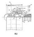
- FIG. 2shows a cut away cross-sectional view of the gas turbine engine with inlet vanes blocking particles during a specific flight condition
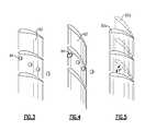
- FIG. 3shows a perspective view of a plurality of variable inlet vanes in a non-diversion position
- FIG. 4shows a perspective view of a plurality of variable inlet vanes in a diversion position
- FIG. 5shows a perspective view of the movement of the plurality of variable inlet vanes between the non-diversion position and the diversion position.
- FIG. 1schematically illustrates a gas turbine engine 20 .
- the gas turbine engine 20is disclosed herein as a two-spool turbofan that generally incorporates a fan section 22 , a compressor section 24 , a combustor section 26 and a turbine section 28 .
- Alternative enginesmight include an augmentor section (not shown) among other systems or features.
- the fan section 22drives air along a bypass flowpath B while the compressor section 24 drives air along a core flowpath C for compression and communication into the combustor section 26 then expansion through the turbine section 28 .
- the engine 20generally includes a low speed spool 30 and a high speed spool 32 mounted for rotation about an engine central longitudinal axis A relative to an engine static structure 36 via several bearing systems 38 . It should be understood that various bearing systems 38 at various locations may alternatively or additionally be provided.
- the low speed spool 30generally includes an inner shaft 40 that interconnects a fan 42 , a low pressure compressor 44 and a low pressure turbine 46 .
- the inner shaft 40is connected to the fan 42 through a geared architecture 48 to drive the fan 42 at a lower speed than the low speed spool 30 .
- the geared architecture 48connects the low pressure compressor 44 to the fan 42 , but allows for rotation of the low pressure compressor 44 at a different speed and/or direction than the fan 42 .
- the high speed spool 32includes an outer shaft 50 that interconnects a high pressure compressor 52 and a high pressure turbine 54 .
- a combustor 56is arranged between the high pressure compressor 52 and the high pressure turbine 54 .
- a mid-turbine frame 58 of the engine static structure 36is arranged generally between the high pressure turbine 54 and the low pressure turbine 46 .
- the mid-turbine frame 58further supports bearing systems 38 in the turbine section 28 .
- the inner shaft 40 and the outer shaft 50are concentric and rotate via bearing systems 38 about the engine central longitudinal axis A which is collinear with their longitudinal axes.
- the core airflowis compressed by the low pressure compressor 44 then the high pressure compressor 52 , mixed and burned with fuel in the combustor 56 , then expanded over the high pressure turbine 54 and low pressure turbine 46 .
- the mid-turbine frame 58includes airfoils 60 that are in the core airflow path.
- the turbines 46 , 54rotationally drive the respective low speed spool 30 and high speed spool 32 in response to the expansion.
- the engine 20is in one example a high-bypass geared aircraft engine.
- the engine 20 bypass ratiois greater than about six (6:1) with an example embodiment being greater than ten (10:1).
- the geared architecture 48is an epicyclic gear train (such as a planetary gear system or other gear system) with a gear reduction ratio of greater than about 2.3 (2.3:1).
- the low pressure turbine 46has a pressure ratio that is greater than about five (5:1).
- the low pressure turbine 46 pressure ratiois pressure measured prior to inlet of low pressure turbine 46 as related to the pressure at the outlet of the low pressure turbine 46 prior to an exhaust nozzle.
- the engine 20 bypass ratiois greater than about ten (10:1), and the fan diameter is significantly larger than that of the low pressure compressor 44 .
- the low pressure turbine 46has a pressure ratio that is greater than about five (5:1).
- the geared architecture 48may be an epicycle gear train, such as a planetary gear system or other gear system, with a gear reduction ratio of greater than about 2.5 (2.5:1). It should be understood, however, that the above parameters are only exemplary of one embodiment of a geared architecture engine and that the present invention is applicable to other gas turbine engines including direct drive turbofans.
- the fan section 22 of the engine 20is designed for a particular flight condition—typically cruise at about 0.8 Mach and about 35,000 feet.
- TSFCis the industry standard parameter of 1 bm of fuel being burned divided by 1 bf of thrust the engine produces at that minimum point.
- Fan pressure ratiois the pressure ratio across the fan blade alone.
- the fan pressure ratio as disclosed herein according to one non-limiting embodimentis less than about 1.6.
- Low corrected fan tip speedis the actual fan tip speed in feet per second divided by an industry standard temperature correction of [(Tambient deg R)/518.7) 0.5 ].
- the “Low corrected fan tip speed” as disclosed herein according to one non-limiting embodimentis less than about 1150 feet per second (351 meters per second).
- Fan exit stators 74are positioned between the fan 42 and the low pressure compressor 44 , and air travels through the fan exit stators 74 to the low pressure compressor through a front center body duct 72 .
- the front center body duct 72can also have variable geometry.
- the low pressure compressor 44includes a plurality of vane stages. In one example, each of the stages can have variable geometry. In one example, the low pressure compressor 44 includes a plurality of variable inlet vanes 62 in a first stage, a plurality of vanes 66 in a second stage, a plurality of vanes 68 in a third stage, and a plurality of exit vanes 70 in a final stage. In one example, the plurality of exit vanes 70 have an inwardly sloping flowpath that connects the low pressure compressor 44 to the high pressure compressor 52 . In one example, only the variable inlet vanes 62 are variable. However, it is possible that vanes 66 , 68 and 70 in the other stages can be variable.
- the variable inlet vanes 62are linked and moveable between a non-diversion position (shown in FIG. 3 ) and a diversion position (shown in FIG. 4 ).
- FIG. 5shows the movement of the vanes 62 between the non-diversion position 62 a (shown in solid lines) and the diversion position 62 b (shown in phantom lines).
- the non-diversion position 62 ais a less obstructing position
- the diversion position 62 bis a more obstructing position.
- the variable inlet vanes 62move an angle X° between about 15° to about 50° from the non-diversion position 62 a to the diversion position 62 b .
- the range of movement of the variable inlet vanes 62is about 15° to about 50°.
- the variable inlet vanes 62are moved to a diversion position 62 b to protect the health of the gas turbine engine 20 .
- the variable inlet vanes 62are moved by an actuator 88 .
- the actuator 88may provide for moving the vanes 62 between the diversion position 62 b and a non-diversion position 62 a and a plurality of intermediate positions therebetween.
- the low pressure compressoralso includes a plurality of rotors or blades 64 between each of the stages of the vanes 62 , 66 , 68 and 70 .
- An inner diameter of the plurality of rotors or blades 64increases for successive stages of rotors 64 in the direction of airflow.
- an outer diameter of the rotors 64 through successive stages in the direction of airflowis nearly cylindrical. This defines a nearly annular flowpath 82 between the outer diameter of the rotors 64 and the outer casing 76 .
- a predetermined vane schedule 92is programmed and stored in a controller 86 and associates vane 62 positions with predetermined flight conditions.
- the vane schedule 92includes values and parameters that are pre-programmed in the controller 86 derived through analysis and testing.
- the programmed flight conditionsare an altitude, a power setting, or both an altitude and a power setting.
- An altimeter 78may determine the altitude of the gas turbine engine 20 .
- the controller 86uses the predetermined vane schedule 92 to position the variable inlet vanes 62 as required by real time flight condition measurements.
- the vane schedule 92is associated with operating characteristics of the low pressure compressor 44 , as well as inclement weather operating parameters for the gas turbine engine 20 .
- the vane schedule 92is associated with operating characteristics of the low pressure compressor 44 in view of only the inclement weather operating parameters for the gas turbine engine 20 .
- Inclement weatheris defined as, or is a precursor to, hail, ice, rain or other environmental factors.
- the controller 86considers the programmed flight conditions of the vane schedule 92 .
- the programmed flight conditionsare established when the chances of encountering hail, ice, dirt, or other foreign objects increases. At these flight conditions, the angle of the variable inlet vanes 62 will be determined to meet the health of the overall gas turbine engine 20 instead of the optimum operability of the low pressure compressor 44 .
- inclement weatheris most likely to affect engine operation during ascent and descent of the gas turbine engine 20 .
- the chance of foreign objects 84 entering the gas turbine engine 20increases when the gas turbine engine 20 is substantially at idle and the gas turbine engine 20 is at an altitude of 10,000 to 25,000 feet.
- the gas turbine engine 20is idle when the low spool is operating at 30% to 70% of the design speed, or bucket cruise, condition.
- At least one flight conditionis monitored, determined and compared by the controller 86 to the vane schedule 92 that considers the programmed flight conditions that are pre-programmed in the controller 86 . If the controller 86 determines that the programmed flight condition are met, the variable inlet vanes 62 are moved.
- the altimeter 78detects that the altitude is between 10,000 and 25,000 feet, the gas turbine engine 20 is idle, or both the altitude is between 10,000 feet and 25,000 feet and the gas turbine engine 20 is idle, the programmed flight conditions are met. At these altitudes, the chance of hail, ice, dirt or other contaminants entering the gas turbine engine 20 increases.
- the controller 86sends a signal to the actuator 88 to move the variable inlet vanes 62 to a diversion position to protect the engine 20 .
- the actuator 88moves the variable inlet vanes 62 to a diversion position to protect the engine 20 .
- FIG. 4when any hail, ice, dirt, foreign objects, or other particles 84 impinge on the variable inlet vanes 62 , the flow of the direction of the particles 84 changes.
- the variable inlet vanes 62deflect any hail, ice, dirt foreign objects, or other particles 84 to flow in the flowpath 82 between an inner surface 80 of an outer casing 76 of the gas turbine engine 20 and an outer diameter of the plurality rotors 64 for extraction with the downstream bleed through a duct 90 .
- variable inlet vanes 62are in the diversion position when the programmed flight conditions are met, regardless of the actual weather conditions. This is important as current control systems are not fast enough to determine the presence of a storm and to react if a storm occurs.
- the variable inlet vanes 62move about 15° to about 50° from the non-diversion position to the diversion position. The exact amount the variable inlet vanes 62 move depends on several factors, among them engine size, engine operability, and the conditions of inclement weather determined by the flight conditions.
- the non-diversion positionis a less obstructing position, and the diversion position is a more obstructing position.
- FIG. 3shows the variable inlet vanes 62 when in a non-diversion position. As compared to FIG. 4 , the variable inlet vanes 62 are at a different angle than shown in FIG. 3 . Any hail, ice, dirt, foreign objects, or other particles 84 flow in the variable inlet vanes 62 . In this example, the hail, ice, dirt, foreign objects, or other particles would not impinge on the variable inlet vanes 62 and could travel inboard and into the low pressure compressor 44 and the high pressure compressor 52 .
- the altitudeis 15,000 feet during an idle descent condition at a maximum aircraft indicated airspeed. At these conditions, the chances of encountering a hailstorm which could cause engine operational issues increases.
- the variable inlet vanes 62moves about 30° from the non-diversion position to the diversion position.
- the gas turbine engine 20can operate during flight conditions that are more likely to expose the gas turbine engine 20 to the presence of hail, ice, dirt, foreign objects, or other particles without adverse responses from the gas turbine engine 20 , optimizing the overall flight cycle.
- vane schedule 92can be employed with a gas turbine engine without a geared architecture.
Landscapes
- Engineering & Computer Science (AREA)
- Mechanical Engineering (AREA)
- General Engineering & Computer Science (AREA)
- Chemical & Material Sciences (AREA)
- Combustion & Propulsion (AREA)
- Aviation & Aerospace Engineering (AREA)
- Physics & Mathematics (AREA)
- Fluid Mechanics (AREA)
- Structures Of Non-Positive Displacement Pumps (AREA)
Abstract
Description
Claims (22)
Priority Applications (3)
| Application Number | Priority Date | Filing Date | Title |
|---|---|---|---|
| US13/446,326US8452516B1 (en) | 2012-01-31 | 2012-04-13 | Variable vane scheduling based on flight conditions for inclement weather |
| EP13743341.3AEP2809926B1 (en) | 2012-01-31 | 2013-01-28 | Variable vane scheduling based on flight conditions for inclement weather |
| PCT/US2013/023357WO2013116125A2 (en) | 2012-01-31 | 2013-01-28 | Variable vane scheduling based on flight conditions for inclement weather |
Applications Claiming Priority (2)
| Application Number | Priority Date | Filing Date | Title |
|---|---|---|---|
| US201261593305P | 2012-01-31 | 2012-01-31 | |
| US13/446,326US8452516B1 (en) | 2012-01-31 | 2012-04-13 | Variable vane scheduling based on flight conditions for inclement weather |
Publications (1)
| Publication Number | Publication Date |
|---|---|
| US8452516B1true US8452516B1 (en) | 2013-05-28 |
Family
ID=48445397
Family Applications (1)
| Application Number | Title | Priority Date | Filing Date |
|---|---|---|---|
| US13/446,326ActiveUS8452516B1 (en) | 2012-01-31 | 2012-04-13 | Variable vane scheduling based on flight conditions for inclement weather |
Country Status (3)
| Country | Link |
|---|---|
| US (1) | US8452516B1 (en) |
| EP (1) | EP2809926B1 (en) |
| WO (1) | WO2013116125A2 (en) |
Cited By (13)
| Publication number | Priority date | Publication date | Assignee | Title |
|---|---|---|---|---|
| EP3054125A1 (en)* | 2015-02-06 | 2016-08-10 | United Technologies Corporation | Variable geometry gas turbine engine for use in inclement weather |
| US20170121027A1 (en)* | 2015-10-30 | 2017-05-04 | Ge Aviation Systems Llc | Enhancing engine performance to improve fuel consumption based on atmospheric rain conditions |
| US9683489B2 (en) | 2013-08-09 | 2017-06-20 | Honeywell International Inc. | System and method for preventing ice crystal accretion in gas turbine engines |
| RU2636201C2 (en)* | 2014-11-24 | 2017-11-21 | Федеральное государственное бюджетное образовательное учреждение высшего образования "Иркутский государственный университет путей сообщения" ФГБОУ ВО ИрГУПС | On-board device for protection of engine from ingestion |
| US10060285B2 (en) | 2013-03-13 | 2018-08-28 | United Technologies Corporation | Variable vane control system |
| US10106267B2 (en) | 2015-10-30 | 2018-10-23 | Ge Aviation Systems Llc | Enhancing engine performance to improve fuel consumption based on atmospheric ice particles |
| EP3412876A1 (en)* | 2017-06-09 | 2018-12-12 | Safran Aero Boosters SA | Variable geometry compressor of axial turbine engine |
| CN109159903A (en)* | 2018-08-23 | 2019-01-08 | 广州创链科技有限公司 | A kind of unmanned vehicle engine progress implication flow modulation device |
| RU2690136C1 (en)* | 2018-03-13 | 2019-05-30 | Федеральное государственное бюджетное образовательное учреждение высшего образования Иркутский государственный университет путей сообщения (ФГБОУ ВО ИрГУПС) | Engine against the ingress of foreign objects protection device |
| US10605166B2 (en) | 2017-04-13 | 2020-03-31 | Pratt & Whitney Canada Corp. | System and method for variable geometry mechanism control |
| US10774788B2 (en) | 2016-06-28 | 2020-09-15 | Raytheon Technologies Corporation | Particle extraction system for a gas turbine engine |
| US10794272B2 (en)* | 2018-02-19 | 2020-10-06 | General Electric Company | Axial and centrifugal compressor |
| CN112343750A (en)* | 2020-10-16 | 2021-02-09 | 中国海洋大学 | Method for predicting real-time power generation capacity of slope wave energy-crossing power generation device |
Citations (54)
| Publication number | Priority date | Publication date | Assignee | Title |
|---|---|---|---|---|
| US3976265A (en) | 1973-05-07 | 1976-08-24 | All American Industries, Inc. | Semibuoyant composite aircraft |
| US3981466A (en) | 1974-12-23 | 1976-09-21 | The Boeing Company | Integrated thermal anti-icing and environmental control system |
| US4004760A (en) | 1975-03-25 | 1977-01-25 | Mitsubishi Jukogyo Kabushiki Kaisha | Device for preventing foreign matters from being sucked into a gas turbine engine for an aircraft |
| US4047379A (en) | 1976-04-28 | 1977-09-13 | General Electric Company | Transient air temperature sensing system |
| US4250703A (en) | 1979-03-15 | 1981-02-17 | Avco Corporation | Swinging door particle separator and deicing system |
| US4308463A (en) | 1970-10-20 | 1981-12-29 | Westinghouse Electric Corp. | System and method for operating industrial gas turbine apparatus and gas turbine electric power plants preferably with a digital computer control system |
| US4380146A (en) | 1977-01-12 | 1983-04-19 | Westinghouse Electric Corp. | System and method for accelerating and sequencing industrial gas turbine apparatus and gas turbine electric power plants preferably with a digital computer control system |
| US4671318A (en) | 1985-02-08 | 1987-06-09 | The Garrett Corporation | Aircraft engine bleed air flow balancing technique |
| US4696156A (en) | 1986-06-03 | 1987-09-29 | United Technologies Corporation | Fuel and oil heat management system for a gas turbine engine |
| US4711084A (en) | 1981-11-05 | 1987-12-08 | Avco Corporation | Ejector assisted compressor bleed |
| US4720237A (en) | 1986-02-24 | 1988-01-19 | United Technologies Corporation | Unison ring actuator assembly |
| US4765131A (en) | 1985-02-08 | 1988-08-23 | Allied Signal Inc. | Aircraft engine bleed air flow balancing technique |
| US4779644A (en) | 1985-02-08 | 1988-10-25 | Allied-Signal Inc. | Aircraft engine bleed air flow balancing technique |
| US4783026A (en) | 1987-05-22 | 1988-11-08 | Avco Corporation | Anti-icing management system |
| US4831819A (en) | 1987-07-02 | 1989-05-23 | Avco Corporation | Anti-icing valve |
| US4852343A (en) | 1987-07-02 | 1989-08-01 | Avco Corporation | Method of operating anti-icing valve |
| US4867635A (en)* | 1987-09-26 | 1989-09-19 | Rolls-Royce Plc | Variable guide vane arrangement for a compressor |
| US4963174A (en) | 1989-12-12 | 1990-10-16 | Payne George K | Hybrid vapor cycle/air cycle environmental control system |
| US5107674A (en) | 1990-03-30 | 1992-04-28 | General Electric Company | Control for a gas turbine engine |
| US5123240A (en) | 1990-03-19 | 1992-06-23 | General Electric Co. | Method and apparatus for ejecting foreign matter from the primary flow path of a gas turbine engine |
| US5168447A (en) | 1983-12-27 | 1992-12-01 | The Boeing Company | Engine trim control unit |
| US5284012A (en) | 1991-05-16 | 1994-02-08 | General Electric Company | Nacelle cooling and ventilation system |
| US5334061A (en) | 1992-09-09 | 1994-08-02 | General Electric Company | Reversing marine gas turbine drive |
| US5351478A (en) | 1992-05-29 | 1994-10-04 | General Electric Company | Compressor casing assembly |
| US5794432A (en)* | 1996-08-27 | 1998-08-18 | Diversitech, Inc. | Variable pressure and variable air flow turbofan engines |
| US6109868A (en) | 1998-12-07 | 2000-08-29 | General Electric Company | Reduced-length high flow interstage air extraction |
| US6119985A (en) | 1997-03-07 | 2000-09-19 | Pioneer Rocketplane Corporation | Reusable rocket-propelled high altitude airplane and method and apparatus for mid-air oxidizer transfer to said airplane |
| US6142418A (en) | 1998-05-12 | 2000-11-07 | Hamilton Sundstrand Corporation | Multi-path secondary power system for an aircraft |
| US6155212A (en) | 1989-06-12 | 2000-12-05 | Mcalister; Roy E. | Method and apparatus for operation of combustion engines |
| US6244034B1 (en) | 1997-12-20 | 2001-06-12 | Alliedsignal, Inc. | Compressor bleed pressure storage for controlled fuel nozzle purging of a turbine power generating system |
| US6408641B1 (en) | 2001-03-27 | 2002-06-25 | Lockheed Martin Corporation | Hybrid turbine coolant system |
| US6499285B1 (en)* | 2001-08-01 | 2002-12-31 | Rolls-Royce Corporation | Particle separator for a gas turbine engine |
| US20030035719A1 (en)* | 2001-08-17 | 2003-02-20 | Wadia Aspi Rustom | Booster compressor deicer |
| US6694746B2 (en) | 2002-02-06 | 2004-02-24 | Honeywell International, Inc. | Micro volume actuator for an air turbine starter |
| US6758044B2 (en)* | 2001-10-10 | 2004-07-06 | Goodrich Pump & Engine Control Systems, Inc. | Control system for positioning compressor inlet guide vanes |
| US6789000B1 (en) | 2002-04-16 | 2004-09-07 | Altek Power Corporation | Microprocessor-based control system for gas turbine electric powerplant |
| US6921244B2 (en) | 2001-12-04 | 2005-07-26 | David L. Johnson | Bleed valve system |
| US20070068171A1 (en)* | 2004-07-21 | 2007-03-29 | Epstein Stanley W | Onboard supplemental power system at varying high altitudes |
| US20080236133A1 (en) | 2007-03-30 | 2008-10-02 | Snecma | Turbomachine front portion comprising a deflector system for deflecting foreign bodies, such as hailstones |
| US7445424B1 (en) | 2006-04-22 | 2008-11-04 | Florida Turbine Technologies, Inc. | Passive thermostatic bypass flow control for a brush seal application |
| US20090126337A1 (en) | 2007-11-20 | 2009-05-21 | Hazzard Robert L | Retrofit dirt separator for gas turbine engine |
| US20090271085A1 (en)* | 2008-04-25 | 2009-10-29 | Lauren Jeanne Buchalter | Method and system for operating gas turbine engine systems |
| US7694505B2 (en) | 2006-07-31 | 2010-04-13 | General Electric Company | Gas turbine engine assembly and method of assembling same |
| US7802433B2 (en) | 2006-09-27 | 2010-09-28 | General Electric Company | Adaptive inertial particle separators and methods of use |
| US7805947B2 (en) | 2005-05-19 | 2010-10-05 | Djamal Moulebhar | Aircraft with disengageable engine and auxiliary power unit components |
| US20100292905A1 (en) | 2009-05-18 | 2010-11-18 | Agrawal Rajendra K | System and method of estimating gas turbine engine performance |
| US7862293B2 (en) | 2007-05-03 | 2011-01-04 | Pratt & Whitney Canada Corp. | Low profile bleed air cooler |
| US7874137B2 (en) | 2007-06-18 | 2011-01-25 | Honeywell International Inc. | Gas turbine engine anti-ice formation device and system |
| US20110079015A1 (en)* | 2009-10-05 | 2011-04-07 | Rolls-Royce Plc | Apparatus and method of operating a gas turbine engine |
| US20110167792A1 (en)* | 2009-09-25 | 2011-07-14 | James Edward Johnson | Adaptive engine |
| US7984684B2 (en) | 2006-10-06 | 2011-07-26 | Mitja Victor Hinderks | Marine hulls and drives |
| US20110208400A1 (en) | 2010-02-23 | 2011-08-25 | Williams International Co., L.L.C. | System and method for contolling a single-spool turboshaft engine |
| US8016232B2 (en) | 2008-05-29 | 2011-09-13 | Honeywell International Inc. | Aircraft cabin pressure descent detection and control system and method |
| US20120070271A1 (en)* | 2010-09-21 | 2012-03-22 | Urban Justin R | Gas turbine engine with bleed duct for minimum reduction of bleed flow and minimum rejection of hail during hail ingestion events |
Family Cites Families (2)
| Publication number | Priority date | Publication date | Assignee | Title |
|---|---|---|---|---|
| US20100287907A1 (en)* | 2009-05-18 | 2010-11-18 | Agrawal Rajendra K | System and method of estimating a gas turbine engine surge margin |
| US8074498B2 (en) | 2009-05-18 | 2011-12-13 | United Technologies Corporation | System and method of assessing thermal energy levels of a gas turbine engine component |
- 2012
- 2012-04-13USUS13/446,326patent/US8452516B1/enactiveActive
- 2013
- 2013-01-28WOPCT/US2013/023357patent/WO2013116125A2/enactiveApplication Filing
- 2013-01-28EPEP13743341.3Apatent/EP2809926B1/enactiveActive
Patent Citations (58)
| Publication number | Priority date | Publication date | Assignee | Title |
|---|---|---|---|---|
| US4308463A (en) | 1970-10-20 | 1981-12-29 | Westinghouse Electric Corp. | System and method for operating industrial gas turbine apparatus and gas turbine electric power plants preferably with a digital computer control system |
| US3976265A (en) | 1973-05-07 | 1976-08-24 | All American Industries, Inc. | Semibuoyant composite aircraft |
| US3981466A (en) | 1974-12-23 | 1976-09-21 | The Boeing Company | Integrated thermal anti-icing and environmental control system |
| US4004760A (en) | 1975-03-25 | 1977-01-25 | Mitsubishi Jukogyo Kabushiki Kaisha | Device for preventing foreign matters from being sucked into a gas turbine engine for an aircraft |
| US4047379A (en) | 1976-04-28 | 1977-09-13 | General Electric Company | Transient air temperature sensing system |
| US4380146A (en) | 1977-01-12 | 1983-04-19 | Westinghouse Electric Corp. | System and method for accelerating and sequencing industrial gas turbine apparatus and gas turbine electric power plants preferably with a digital computer control system |
| US4250703A (en) | 1979-03-15 | 1981-02-17 | Avco Corporation | Swinging door particle separator and deicing system |
| US4711084A (en) | 1981-11-05 | 1987-12-08 | Avco Corporation | Ejector assisted compressor bleed |
| US5168447A (en) | 1983-12-27 | 1992-12-01 | The Boeing Company | Engine trim control unit |
| US4671318A (en) | 1985-02-08 | 1987-06-09 | The Garrett Corporation | Aircraft engine bleed air flow balancing technique |
| US4765131A (en) | 1985-02-08 | 1988-08-23 | Allied Signal Inc. | Aircraft engine bleed air flow balancing technique |
| US4779644A (en) | 1985-02-08 | 1988-10-25 | Allied-Signal Inc. | Aircraft engine bleed air flow balancing technique |
| US4720237A (en) | 1986-02-24 | 1988-01-19 | United Technologies Corporation | Unison ring actuator assembly |
| US4696156A (en) | 1986-06-03 | 1987-09-29 | United Technologies Corporation | Fuel and oil heat management system for a gas turbine engine |
| US4741152A (en) | 1986-06-03 | 1988-05-03 | United Technologies Corporation | Fuel and oil heat management system for a gas turbine engine |
| US4783026A (en) | 1987-05-22 | 1988-11-08 | Avco Corporation | Anti-icing management system |
| US4831819A (en) | 1987-07-02 | 1989-05-23 | Avco Corporation | Anti-icing valve |
| US4852343A (en) | 1987-07-02 | 1989-08-01 | Avco Corporation | Method of operating anti-icing valve |
| US4867635A (en)* | 1987-09-26 | 1989-09-19 | Rolls-Royce Plc | Variable guide vane arrangement for a compressor |
| US6155212A (en) | 1989-06-12 | 2000-12-05 | Mcalister; Roy E. | Method and apparatus for operation of combustion engines |
| US4963174A (en) | 1989-12-12 | 1990-10-16 | Payne George K | Hybrid vapor cycle/air cycle environmental control system |
| US5123240A (en) | 1990-03-19 | 1992-06-23 | General Electric Co. | Method and apparatus for ejecting foreign matter from the primary flow path of a gas turbine engine |
| US5107674A (en) | 1990-03-30 | 1992-04-28 | General Electric Company | Control for a gas turbine engine |
| US5284012A (en) | 1991-05-16 | 1994-02-08 | General Electric Company | Nacelle cooling and ventilation system |
| US5351476A (en) | 1991-05-16 | 1994-10-04 | General Electric Company | Nacelle cooling and ventilation system |
| US5351478A (en) | 1992-05-29 | 1994-10-04 | General Electric Company | Compressor casing assembly |
| US5334061A (en) | 1992-09-09 | 1994-08-02 | General Electric Company | Reversing marine gas turbine drive |
| US5794432A (en)* | 1996-08-27 | 1998-08-18 | Diversitech, Inc. | Variable pressure and variable air flow turbofan engines |
| US6119985A (en) | 1997-03-07 | 2000-09-19 | Pioneer Rocketplane Corporation | Reusable rocket-propelled high altitude airplane and method and apparatus for mid-air oxidizer transfer to said airplane |
| US6244034B1 (en) | 1997-12-20 | 2001-06-12 | Alliedsignal, Inc. | Compressor bleed pressure storage for controlled fuel nozzle purging of a turbine power generating system |
| US6142418A (en) | 1998-05-12 | 2000-11-07 | Hamilton Sundstrand Corporation | Multi-path secondary power system for an aircraft |
| US6109868A (en) | 1998-12-07 | 2000-08-29 | General Electric Company | Reduced-length high flow interstage air extraction |
| US6408641B1 (en) | 2001-03-27 | 2002-06-25 | Lockheed Martin Corporation | Hybrid turbine coolant system |
| US6499285B1 (en)* | 2001-08-01 | 2002-12-31 | Rolls-Royce Corporation | Particle separator for a gas turbine engine |
| US20030035719A1 (en)* | 2001-08-17 | 2003-02-20 | Wadia Aspi Rustom | Booster compressor deicer |
| US6561760B2 (en) | 2001-08-17 | 2003-05-13 | General Electric Company | Booster compressor deicer |
| US6758044B2 (en)* | 2001-10-10 | 2004-07-06 | Goodrich Pump & Engine Control Systems, Inc. | Control system for positioning compressor inlet guide vanes |
| US6921244B2 (en) | 2001-12-04 | 2005-07-26 | David L. Johnson | Bleed valve system |
| US6694746B2 (en) | 2002-02-06 | 2004-02-24 | Honeywell International, Inc. | Micro volume actuator for an air turbine starter |
| US6789000B1 (en) | 2002-04-16 | 2004-09-07 | Altek Power Corporation | Microprocessor-based control system for gas turbine electric powerplant |
| US6941217B1 (en) | 2002-04-16 | 2005-09-06 | Altek Power Corporation | Microprocessor-based control system for gas turbine electric powerplant |
| US20070068171A1 (en)* | 2004-07-21 | 2007-03-29 | Epstein Stanley W | Onboard supplemental power system at varying high altitudes |
| US7805947B2 (en) | 2005-05-19 | 2010-10-05 | Djamal Moulebhar | Aircraft with disengageable engine and auxiliary power unit components |
| US7445424B1 (en) | 2006-04-22 | 2008-11-04 | Florida Turbine Technologies, Inc. | Passive thermostatic bypass flow control for a brush seal application |
| US7694505B2 (en) | 2006-07-31 | 2010-04-13 | General Electric Company | Gas turbine engine assembly and method of assembling same |
| US7802433B2 (en) | 2006-09-27 | 2010-09-28 | General Electric Company | Adaptive inertial particle separators and methods of use |
| US7984684B2 (en) | 2006-10-06 | 2011-07-26 | Mitja Victor Hinderks | Marine hulls and drives |
| US20080236133A1 (en) | 2007-03-30 | 2008-10-02 | Snecma | Turbomachine front portion comprising a deflector system for deflecting foreign bodies, such as hailstones |
| US7862293B2 (en) | 2007-05-03 | 2011-01-04 | Pratt & Whitney Canada Corp. | Low profile bleed air cooler |
| US7874137B2 (en) | 2007-06-18 | 2011-01-25 | Honeywell International Inc. | Gas turbine engine anti-ice formation device and system |
| US20090126337A1 (en) | 2007-11-20 | 2009-05-21 | Hazzard Robert L | Retrofit dirt separator for gas turbine engine |
| US20090271085A1 (en)* | 2008-04-25 | 2009-10-29 | Lauren Jeanne Buchalter | Method and system for operating gas turbine engine systems |
| US8016232B2 (en) | 2008-05-29 | 2011-09-13 | Honeywell International Inc. | Aircraft cabin pressure descent detection and control system and method |
| US20100292905A1 (en) | 2009-05-18 | 2010-11-18 | Agrawal Rajendra K | System and method of estimating gas turbine engine performance |
| US20110167792A1 (en)* | 2009-09-25 | 2011-07-14 | James Edward Johnson | Adaptive engine |
| US20110079015A1 (en)* | 2009-10-05 | 2011-04-07 | Rolls-Royce Plc | Apparatus and method of operating a gas turbine engine |
| US20110208400A1 (en) | 2010-02-23 | 2011-08-25 | Williams International Co., L.L.C. | System and method for contolling a single-spool turboshaft engine |
| US20120070271A1 (en)* | 2010-09-21 | 2012-03-22 | Urban Justin R | Gas turbine engine with bleed duct for minimum reduction of bleed flow and minimum rejection of hail during hail ingestion events |
Non-Patent Citations (2)
| Title |
|---|
| Gunston, Bill, "Jane's Aero-Engines," Issue Seven, 2000, pp. 510-512. |
| International Search Report and Written Opinion for PCT Application No. PCT/US2013/023357 mailed Mar. 27, 2013. |
Cited By (17)
| Publication number | Priority date | Publication date | Assignee | Title |
|---|---|---|---|---|
| US10060285B2 (en) | 2013-03-13 | 2018-08-28 | United Technologies Corporation | Variable vane control system |
| US9683489B2 (en) | 2013-08-09 | 2017-06-20 | Honeywell International Inc. | System and method for preventing ice crystal accretion in gas turbine engines |
| RU2636201C2 (en)* | 2014-11-24 | 2017-11-21 | Федеральное государственное бюджетное образовательное учреждение высшего образования "Иркутский государственный университет путей сообщения" ФГБОУ ВО ИрГУПС | On-board device for protection of engine from ingestion |
| US10495006B2 (en) | 2015-02-06 | 2019-12-03 | United Technologies Corporation | Variable geometry gas turbine engine for use in inclement weather |
| EP3054125A1 (en)* | 2015-02-06 | 2016-08-10 | United Technologies Corporation | Variable geometry gas turbine engine for use in inclement weather |
| US20160230677A1 (en)* | 2015-02-06 | 2016-08-11 | United Technologies Corporation | Variable Geometry Gas Turbine Engine For Use In Inclement Weather |
| US9938017B2 (en)* | 2015-10-30 | 2018-04-10 | Ge Aviation Systems Llc | Enhancing engine performance to improve fuel consumption based on atmospheric rain conditions |
| US10106267B2 (en) | 2015-10-30 | 2018-10-23 | Ge Aviation Systems Llc | Enhancing engine performance to improve fuel consumption based on atmospheric ice particles |
| US20170121027A1 (en)* | 2015-10-30 | 2017-05-04 | Ge Aviation Systems Llc | Enhancing engine performance to improve fuel consumption based on atmospheric rain conditions |
| US10774788B2 (en) | 2016-06-28 | 2020-09-15 | Raytheon Technologies Corporation | Particle extraction system for a gas turbine engine |
| US10605166B2 (en) | 2017-04-13 | 2020-03-31 | Pratt & Whitney Canada Corp. | System and method for variable geometry mechanism control |
| BE1025299B1 (en)* | 2017-06-09 | 2019-01-14 | Safran Aero Boosters S.A. | COMPRESSOR WITH VARIABLE GEOMETRY OF TURBOMACHINE AXIA |
| EP3412876A1 (en)* | 2017-06-09 | 2018-12-12 | Safran Aero Boosters SA | Variable geometry compressor of axial turbine engine |
| US10794272B2 (en)* | 2018-02-19 | 2020-10-06 | General Electric Company | Axial and centrifugal compressor |
| RU2690136C1 (en)* | 2018-03-13 | 2019-05-30 | Федеральное государственное бюджетное образовательное учреждение высшего образования Иркутский государственный университет путей сообщения (ФГБОУ ВО ИрГУПС) | Engine against the ingress of foreign objects protection device |
| CN109159903A (en)* | 2018-08-23 | 2019-01-08 | 广州创链科技有限公司 | A kind of unmanned vehicle engine progress implication flow modulation device |
| CN112343750A (en)* | 2020-10-16 | 2021-02-09 | 中国海洋大学 | Method for predicting real-time power generation capacity of slope wave energy-crossing power generation device |
Also Published As
| Publication number | Publication date |
|---|---|
| EP2809926A2 (en) | 2014-12-10 |
| WO2013116125A3 (en) | 2014-10-30 |
| EP2809926A4 (en) | 2015-11-04 |
| EP2809926B1 (en) | 2018-09-19 |
| WO2013116125A2 (en) | 2013-08-08 |
Similar Documents
| Publication | Publication Date | Title |
|---|---|---|
| US8452516B1 (en) | Variable vane scheduling based on flight conditions for inclement weather | |
| US20200095929A1 (en) | High thrust geared gas turbine engine | |
| US10280757B2 (en) | Gas turbine engine airfoil with auxiliary flow channel | |
| US9957832B2 (en) | Variable area turbine | |
| US20230175433A1 (en) | Geared turbofan architecture | |
| EP3249199B1 (en) | Gas turbine engine inlet temperature sensor configuration and corresponding method | |
| US20130195645A1 (en) | Geared turbomachine architecture having a low profile core flow path contour | |
| EP2932049B1 (en) | Overmolded vane platform | |
| US10519796B2 (en) | Variable area turbine vane row assembly | |
| EP2809929B1 (en) | High turning fan exit stator | |
| EP3019728B1 (en) | Three spool geared turbofan with low pressure compressor drive gear system | |
| US10060390B2 (en) | Bypass duct with angled drag links | |
| US10502089B2 (en) | Gas turbine engine variable stator vane | |
| US10563672B2 (en) | Gas turbine engine compressor | |
| US11391205B2 (en) | Anti-icing core inlet stator assembly for a gas turbine engine | |
| US11073087B2 (en) | Gas turbine engine variable pitch fan blade | |
| EP2900982B1 (en) | Variable vane scheduling | |
| EP2952693A2 (en) | Case with vane retention feature | |
| US20200080442A1 (en) | Airfoil assembly for a gas turbine engine | |
| US20150233298A1 (en) | Reduction in jet flap interaction noise with geared turbine engine | |
| US12326114B2 (en) | Gas turbine engine with core debris protection | |
| US20140093355A1 (en) | Extended indentation for a fastener within an air flow |
Legal Events
| Date | Code | Title | Description |
|---|---|---|---|
| AS | Assignment | Owner name:UNITED TECHNOLOGIES CORPORATION, CONNECTICUT Free format text:ASSIGNMENT OF ASSIGNORS INTEREST;ASSIGNORS:ROSE, BECKY E.;BRILLIANT, LISA I.;REEL/FRAME:028043/0006 Effective date:20120412 | |
| STCF | Information on status: patent grant | Free format text:PATENTED CASE | |
| FPAY | Fee payment | Year of fee payment:4 | |
| AS | Assignment | Owner name:RAYTHEON TECHNOLOGIES CORPORATION, MASSACHUSETTS Free format text:CHANGE OF NAME;ASSIGNOR:UNITED TECHNOLOGIES CORPORATION;REEL/FRAME:054062/0001 Effective date:20200403 | |
| MAFP | Maintenance fee payment | Free format text:PAYMENT OF MAINTENANCE FEE, 8TH YEAR, LARGE ENTITY (ORIGINAL EVENT CODE: M1552); ENTITY STATUS OF PATENT OWNER: LARGE ENTITY Year of fee payment:8 | |
| AS | Assignment | Owner name:RAYTHEON TECHNOLOGIES CORPORATION, CONNECTICUT Free format text:CORRECTIVE ASSIGNMENT TO CORRECT THE AND REMOVE PATENT APPLICATION NUMBER 11886281 AND ADD PATENT APPLICATION NUMBER 14846874. TO CORRECT THE RECEIVING PARTY ADDRESS PREVIOUSLY RECORDED AT REEL: 054062 FRAME: 0001. ASSIGNOR(S) HEREBY CONFIRMS THE CHANGE OF ADDRESS;ASSIGNOR:UNITED TECHNOLOGIES CORPORATION;REEL/FRAME:055659/0001 Effective date:20200403 | |
| AS | Assignment | Owner name:RTX CORPORATION, CONNECTICUT Free format text:CHANGE OF NAME;ASSIGNOR:RAYTHEON TECHNOLOGIES CORPORATION;REEL/FRAME:064714/0001 Effective date:20230714 | |
| MAFP | Maintenance fee payment | Free format text:PAYMENT OF MAINTENANCE FEE, 12TH YEAR, LARGE ENTITY (ORIGINAL EVENT CODE: M1553); ENTITY STATUS OF PATENT OWNER: LARGE ENTITY Year of fee payment:12 |