US8452299B2 - Allocating code space to base stations - Google Patents
Allocating code space to base stationsDownload PDFInfo
- Publication number
- US8452299B2 US8452299B2US11/962,983US96298307AUS8452299B2US 8452299 B2US8452299 B2US 8452299B2US 96298307 AUS96298307 AUS 96298307AUS 8452299 B2US8452299 B2US 8452299B2
- Authority
- US
- United States
- Prior art keywords
- base station
- portable base
- code space
- signal strength
- offset
- Prior art date
- Legal status (The legal status is an assumption and is not a legal conclusion. Google has not performed a legal analysis and makes no representation as to the accuracy of the status listed.)
- Expired - Fee Related, expires
Links
Images


Classifications
- H—ELECTRICITY
- H04—ELECTRIC COMMUNICATION TECHNIQUE
- H04W—WIRELESS COMMUNICATION NETWORKS
- H04W24/00—Supervisory, monitoring or testing arrangements
- H04W24/10—Scheduling measurement reports ; Arrangements for measurement reports
- H—ELECTRICITY
- H04—ELECTRIC COMMUNICATION TECHNIQUE
- H04J—MULTIPLEX COMMUNICATION
- H04J13/00—Code division multiplex systems
- H—ELECTRICITY
- H04—ELECTRIC COMMUNICATION TECHNIQUE
- H04J—MULTIPLEX COMMUNICATION
- H04J13/00—Code division multiplex systems
- H04J13/16—Code allocation
- H—ELECTRICITY
- H04—ELECTRIC COMMUNICATION TECHNIQUE
- H04W—WIRELESS COMMUNICATION NETWORKS
- H04W72/00—Local resource management
- H04W72/50—Allocation or scheduling criteria for wireless resources
- H04W72/54—Allocation or scheduling criteria for wireless resources based on quality criteria
- H—ELECTRICITY
- H04—ELECTRIC COMMUNICATION TECHNIQUE
- H04W—WIRELESS COMMUNICATION NETWORKS
- H04W88/00—Devices specially adapted for wireless communication networks, e.g. terminals, base stations or access point devices
- H04W88/08—Access point devices
Definitions
- This disclosurerelates to using base stations to detect and assign available code space.
- Cellular wireless communication systemsmay be designed to serve many mobile handsets.
- One technique for sharing wireless communications bandwidthis code-division multiple access (CDMA), in which bandwidth may be divided by incorporating portions of a code space into communication signals of a cellular system.
- CDMAcode-division multiple access
- By assigning different timing offsets of the code to transmission base stations of the systemmultiple wireless signals may coexist in space, time, and frequency without substantially interfering with one another.
- the code space portions and associated timing offsets used by the base stationsare typically assigned during system development based upon an overall cellular network design.
- a portable base stationrequests a mobile handset to measure signal strengths associated with a portion of a code space.
- the portable base stationalso sends a message that represents the signal strength measurements to a remotely located control station.
- a portion of the code space for use by the portable base stationmay be selected, based at least in part upon the measurements of signal strength.
- the request for signal strength measurementmay include identifying a portion of code space in which to measure signal strength.
- the identified portion of code spacemay be selected based upon the geographic location of the portable base station.
- the code spacemay include one or more sequences of pseudorandom numbers and associated timing offsets.
- the portable base stationmay receive a message from the control station that identifies a portion of code space assigned to the portable base station.
- an apparatusincludes a portable base station that is configured to request a mobile handset to measure signal strengths associated with a portion of a code space.
- the portable base stationis also configured to send a message that represents the signal strength measurements to a remotely located control station.
- the portable base stationmay also be configured to select a portion of the code space for use by the portable base station, based at least in part upon the measurements of signal strength.
- the portable base stationmay also be configured identify a portion of code space in which to request measurements of signal strength. The identified portion of code space may be selected based upon the geographic location of the portable base station.
- the code spacemay include one or more sequences of pseudorandom numbers and associated timing offsets.
- the portable base stationmay also be configured to receive a message that identifies a portion of the code space assigned to the portable base station from the control station.
- a systemin some aspects of the disclosure, includes a portable base station configured to request a mobile handset to measure signal strength associated with elements of a code space.
- the portable base stationis also configured to send a message that represents received signal strength measurements.
- the systemalso includes a control station configured to assign a portion of the code space to the portable base station based in part upon said signal strength measurements.
- the portable base stationmay also be configured to select, based at least in part upon geographic location of the portable base station, a portion of code space in which to request measurements of signal strength.
- the code spacemay include one or more sequences of pseudorandom numbers and associated timing offsets.
- the portable base stationmay also be configured to calculate a weighted average of signal strength measurements from multiple mobile handsets for one or more code space elements.
- a computer readable mediumstores instructions that are executable by a processing device, and upon such execution cause the processing device to send a request to measure signal strengths associated with a portion of a code space from a portable base station to a mobile handset.
- the mediumalso stores instructions to cause the processing device to send a message that represents the signal strength measurements to a remotely located control station from the portable base station.
- the instructionsmay cause the processing device to select a portion of the code space for use by the portable base station, based at least in part upon the measurements of signal strength.
- the instructionsmay cause the processing device to identify a portion of code space in which to measure signal strength. The identified portion of code space may be selected based upon the geographic location of the portable base station.
- the code spacemay include one or more sequences of pseudorandom numbers and associated timing offsets.
- the instructionsmay also cause the processing device to receive a message at the portable base station that identifies a portion of code space assigned to the portable base station from the control station.
- an apparatusin some aspects of the disclosure, includes a portable antenna configured to transmit and receive electromagnetic signals.
- the apparatusalso includes a portable base station connected to the portable antenna.
- the portable base stationincludes a radio node configured to control the portable antenna and to comply with at least one wireless communication protocol.
- the portable base stationalso includes a radio node controller configured to provide transmission signals to the radio node and receive signals from the radio node to establish a connection between the portable base station and a mobile handset.
- the radio node controlleris also configured to request the mobile handset measure signal strength associated with a portion of a code space.
- the portable base stationalso includes an access gateway for exchanging data packets with a network. The access gateway is configured to send a message that represents the measured signal strength to a remotely located control station.
- the portable base stationmay send a TrafficChannelAssignment message to the mobile handset to request the signal strength measurement.
- the portable base stationmay alternatively send an ExtendedChannelAssignment message to the mobile handset to request the signal strength measurement.
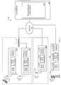
- FIG. 1is a block diagram of a radio access network and a core network.
- FIG. 2illustrates information exchanging among a mobile handset, a portable base station and a service manager.
- FIGS. 3-5show lists of PN offsets and signal strengths.
- FIG. 6is a flow chart of some operations of a PN offset monitor.
- a radio access network (RAN) 100includes multiple base stations that may bi-directionally communicate through a network 102 (e.g., a base station subsystem (BSS), a mobile switching center (MSC), etc.) with a core network 104 (e.g., a global system for mobile communications (GSM), general packet radio services (GPRS) system, etc.).
- the RAN 100includes a conventional antenna tower 106 that is erected at a fixed location and transmits and receives electromagnetic signals that are provided to and from a fixed location base station 108 .
- One or more signaling techniques and standardsmay be implemented by the fixed location base station 108 to establish communication links (via the antenna tower 106 ) with one or more mobile handsets such as cellular telephones.
- UMTSUniversal Mobile Telecommunications System
- UMTSUniversal Mobile Telecommunications System
- Standards associated with spread spectrum air interface protocolssuch as code division multiple access (CDMA), wideband (W-CDMA), etc. may also be implemented for multiple mobile handsets for establishing communication links.
- CDMAcode division multiple access
- W-CDMAwideband
- 1xEV-DO protocolis an evolution of the 1xRTT standard for high-speed data-only (DO) services and has been standardized by the Telecommunication Industry Association (TIA) as TIA/EIA/IS-856, “CDMA2000 High Rate Packet Data Air Interface Specification”, 3GPP2 C.S0024-0, Version 4.0, Oct. 25, 2002, which is incorporated herein by reference.
- TIA/EIA/IS-856“CDMA2000 High Rate Packet Data Air Interface Specification”
- 3GPP2 C.S0024-AVersion 2.0, June 2005, which is also incorporated herein by reference.
- the fixed location base station 108may transmit a signal (via the antenna 106 ) that uses one or more spread spectrum techniques such as being modulated with a unique pseudorandom code.
- the identification signalmay appear as noise, however, the signal may be extracted (e.g., with a correlation process) by an appropriate receiver.
- orthogonal coding techniquesBy implementing such spread spectrum techniques or orthogonal coding techniques, a mobile handset may distinguish base station identities and the probability of identification signal interference may be reduced.
- Other types of orthogonal or non-orthogonal coding techniquesmay also be used to produce unique transmission signals. For example, one or more PN sequences (e.g., gold sequences) referred to as scrambling codes (e.g., for W-CDMA) may be implemented.
- One or more types of informationmay also be transmitted to uniquely identify the base station 108 such as transmitting data uniquely assigned to the base station 108 .
- the fixed location base station 108includes a radio node (RN) 112 that may support one or more wireless standards and protocols (e.g., CDMA, W-CDMA, UMTS, etc.) for communicating with the mobile handsets.
- RN 112includes a transceiver for receiving and transmitting electromagnetic signals and may also include one or more components (e.g., a modulator/demodulator (MODEM)) for modulating a transmission carrier signal to encode digital information for transmission or demodulating a received signal to decode transmitted information.
- MODEMmodulator/demodulator
- the base station 108may also include a radio node controller (RNC) 114 that provides commands (and transmission signals) to the RN 112 and receives incoming signals from the RN.
- the base station 110may also include an access gateway 116 such as a packet data serving node (PDSN) and may be implemented as a data server to direct data packets to appropriate delivery locations. Additionally the access gateway 116 may provide an interface between networking functions and service levels defined by one or more standards such as the Open Systems Interconnect (OSI) protocol standard as provided by the International Standards Organization (ISO), which is herein incorporated by reference.
- OSIOpen Systems Interconnect
- ISOInternational Standards Organization
- Antenna towerssuch as the antenna tower 106 are erected to typically remain fixed at one location. Prior to erecting the towers, the geographical layout of the towers is planned for providing appropriate wireless coverage. Additionally, each tower is assigned a portion of a code space so that the antenna (and the corresponding fixed location base station) may uniquely identify itself to the one or more mobile handsets within the coverage area. Since mobile handsets such as a mobile handset 110 may communicate with base stations (e.g., CDMA, W-CDMA and UMTS base stations) with equivalent frequencies, the mobile handset needs to differentiate one fixed location base station from another.
- base stationse.g., CDMA, W-CDMA and UMTS base stations
- each base stationmay repeatedly transmit a sequence of pseudorandom numbers (PN) that is offset from PN sequences being transmitted by the other base stations.
- PNpseudorandom numbers
- the PN offsetis assigned to each fixed location base station respectively connected to an antenna erected at a fixed location.
- these offset assignmentsare determined prior to the antenna tower becoming operational and the offsets are permanently assigned once the tower is in operation.
- such a manual offset assignment processis often time-consuming and expensive since the assignments need to be completed before tower erection.
- an equivalent PN sequenceis transmitted from each fixed antenna; however, in some scenarios different PN-sequences may be transmitted to uniquely identify base stations.
- different frequenciesmay be used for signal transmission.
- the RAN 100also includes a portable base station 118 that is in communication with the core network 104 and provides the functionality of the fixed location base station 108 along with being portable.
- the portable base station 118may include an RN 120 , an RNC 122 and an access gateway 124 (e.g., a PSDN).
- the portable base station 118is connected to a portable antenna 126 that is capable of establishing links with one or more mobile handsets.
- the characteristics of the portable antenna 126e.g., beam pattern, gain, etc. may be selected for establishing links to mobile handsets located relatively close to the portable base station 118 .
- the portable base station 118may provide less wireless coverage area than the fixed location base station 108 (e.g., coverage to service a single residential home, a portion of a multiple residence building or other structure or location of similar size and area). However, due to its mobility, the portable base station 118 may interfere with the operations of the fixed location base station 108 or other relatively closely located base stations (e.g., other portable base stations, fixed location base stations, etc.).
- identification signals transmitted by the portable base station 118may interfere with base stations using near-by or equivalent code space (e.g., PN offset, PN sequence, etc.). Since the code space usage in the area that a portable base station operates is not known a priori, the PN offset used by the portable base station is typically configured adaptively at power up. The PN offset assignment may be periodically updated thereafter to adapt to changes in the environment, such as the arrival of additional portable base stations in the area.
- code spacee.g., PN offset, PN sequence, etc.
- a portable base station 128 and a portable base station 130are located nearby and are connected to the network 102 through a router 132 .
- Use of multiple portable base stationsmay allow, for example, access interfaces for mobile handsets within a campus area (e.g., university, medical, or government facility, housing development, etc.) or other types of locations.
- the number of PN offsets availableis limited. When many portable base stations operate within the coverage area of the same fixed base station, the need for PN offset reuse may arise.
- the interference caused by sharing PN offsets within an areacan be mitigated by allocating the PN offsets in a manner that ensures portable base stations assigned to the same PN offset are relatively distant from each other.
- the core network 104may exchange data and signals with other components included in or in communication with the RAN 100 .
- datamay be sent to other base stations, conventional landline telephone systems (e.g., Plain Old Telephone Service (POTS) systems, etc.) or other similar delivery sites and sources.
- POTSPlain Old Telephone Service
- a service manager control station 134via communication with the core network 104 , dynamically allocates code space (e.g., one or more PN sequences) and assigns portions of the code space (e.g., PN offsets, PN sequences, etc.) to each of the portable base stations 118 , 128 , 130 (and optionally, the fixed location base station 108 ).
- code spacee.g., one or more PN sequences
- portions of the code spacee.g., PN offsets, PN sequences, etc.
- Location tracking, PN offset assignment storage, and other functionsmay also be provided by the control station 134 such as tracking the location of the base stations (e.g., portable base stations, fixed location base stations).
- the control station 134assigns an appropriate PN offset to a portable base station based upon the strength of signals (with PN offsets) in the vicinity of the portable base station. For example, a PN offset may be assigned that corresponds to a relatively weak signal (that includes the PN offset) or an offset that is not observed to be associated with any signals in the vicinity of the portable base station.
- One or more techniques and methodologiesmay be implemented for measuring signal strength.
- the portable base stationmay request a mobile handset (in communication with the base station) to measure the strength of signals in the vicinity.
- the service manager control station 134may also store PN offset assignments along with other information (e.g., base station location information, base station capabilities, assignment confirmations, etc.).
- encryption techniquesmay be implemented to reduce the probability of interception or modification of PN offset assignments.
- a portable base stationmay be initialized (e.g., upon power-up) with a default PN offset, for example, by a setting or group of settings entered by a manufacturer or other entity. Other information may also be used for setting a default, for example, a portable base station may select a default PN offset based upon the region (e.g., time zone, GPS coordinates, etc.) in which the base station is located upon activation.
- a portable base stationmay request an initial PN offset by using one or more techniques such as transmitting a signal, an electronic message, a file, a data structure, or another similar methodology. For example, a portable base station may request a default PN offset from the service manager control station 134 upon becoming operational (e.g., powered up) and establishing communication with the core network 104 .
- PN offset (or PN sequence) assignmentsmay be initiated by a predefined (or undefined) event such as the portable base station 130 being powered up, establishing a communication link with the core network 104 , and establishing a connection with a mobile handset (e.g., the mobile handset 110 ).
- the portable base station 130may request that the mobile handset 110 measure the strength of detectable signals associated with base stations in the vicinity.
- a messagemay be sent by the portable base station 130 to the service manager control station 134 to request a PN offset assignment.
- Such messagesmay include information regarding the PN offsets and associated signal strengths of the nearby base stations along with mobile handset and base station information.
- the service manager control station 134may use the PN offsets provided by the message received from the portable base station 130 (e.g., the weakest PN offset signal within range of the mobile handset 110 ) or assign a PN offset associated with signal not detected by the mobile handset (or currently not assigned to a base station).
- the other portable base stations 118 , 128may request a PN offset (or other type of code space portion) upon becoming operational.
- events that initiate a PN offset requestmay include the occurrence of predefined time (e.g., midnight each evening), resetting the portable base station, user initiated, or other type of similar event.
- the PN offset assignment request sent to the service manager control station 134may contain information such as data that identifies the base station (e.g., a unique alphanumerical identifier assigned to the base station by a manufacturer, etc.), the location of the portable base station (e.g., GPS coordinates), base station capabilities (e.g., coverage area, transmission power, etc.), status information (e.g., number of established mobile handset links) and other types of information.
- GPS coordinatesmay be inserted into the message from a GPS receiver (not shown) that is included in the base station.
- Location informationmay also be provided from an external source such as an external GPS receiver or other type of location determining device in communication with the base station.
- Data that represents a previously used PN offsetmay also be included in the message.
- Informationsuch as location information may be provided to a portable base station from a user interface (e.g., a keyboard) or a data conduit (e.g., communication port) from another device (e.g., a GPS receiver).
- a user interfacee.g., a keyboard
- a data conduite.g., communication port
- Other included informationmay be used for security (e.g., a public key, etc.), data compression, or other types of functions.
- a PN offset monitoring element within or attached to the portable base stationmay execute operations for providing the portable base station 130 with a default PN offset.
- the PN offset monitoring elementmay initiate signal collection in the vicinity of the base station for identifying the PN offset associated with the weakest signal (or determining the absence of a signal with a particular PN offset).
- the PN offset monitoring elementmay notify the service manager control station 134 of the PN offset for assignment initiation.
- the PN offset monitoring elementmay instead select a PN offset as a default which the portable base station may initially broadcast.
- the portable base stations 118 , 128 , 130may communicate via a local area network (LAN) connecting to an internet protocol (IP) core network to obtain a default PN offset and/or a PN offset assignment.
- the portable base station 128could connect to the IP core network via a wireless modem to a wireless LAN (WLAN) to communicate with a service manager control station.
- the portable base station 128could be in communication with a computer device 132 which have Internet and/or intranet connectivity (e.g., via cable modem, wireless modem, etc.).
- the portable base stations 118 , 128 , 132may also communicate with mobile devices within the RAN 100 .
- Other network communication schemesare possible.
- the portable base station 130may broadcast a signal that includes a PN sequence with a default PN offset (e.g., assigned by the base station manufacturer) for self-identification and for establishing communication links with mobile handsets.
- the mobile handset 110may implement one or more techniques for measuring base station signal emissions.
- One or more types of measurement commands 206may be issued by the portable base station 130 to initiate signal strength measurements by the mobile handset 110 .
- the measurement command 206may depend upon the protocol being used to communicate between the portable base station 130 and the mobile handset 110 .
- a messagesuch as the TrafficChannelAssignment message may be sent, while a message such as the ExtendedChannelAssignment message may be sent for arrangements in which the RAN uses the 1XRTT protocol.
- Messages that comply with the GSM and UMTS standardsmay also be used as measurement triggers.
- Such commandsinstruct the mobile handset 110 to measure the strength of signals associated with base stations which are in active connection with the mobile handset (referred to as active base stations) and/or base stations which are in a state capable of establishing a connection with a mobile handset (referred to as candidate base stations).
- active base stationsbase stations which are in active connection with the mobile handset
- candidate base stationsbase stations which are in a state capable of establishing a connection with a mobile handset
- the base station that the mobile handset 110 is presently connected toe.g., the portable base station 130
- the base station that the mobile handset 110 is presently connected tomay be considered an active base station.
- the measurement command 206may contain additional information such as a list of PN offsets for which the mobile handset 110 is to obtain a signal strength measurement.
- the PN offsets included in the listmay be associated, for example, with the geographic location of the base stations.
- Such base station geographic informationmay be provided by one or more techniques such as factory presets, user provided information and setting, base station functionality (e.g., a built-in GPS receiver), etc. If a subset of the PN offset range is significant to a particular geographic region, the mobile handset 110 can be instructed to search for the geographic subset of the full list of PN offsets.
- the listmay include a range of PN offsets based upon previous code space allocations, communication standard compliance (e.g., PN offsets available based on the CDMA specification, etc) and other methodologies. For example, 512 total PN offsets may be available within the CDMA specification.
- the measurement command 206initiates placing PN offsets into an active and/or candidate base station status within the mobile handset 110 . Through promoting PN offsets to the active and/or candidate status, the mobile handset 110 may begin to actively monitor those PN offsets for signal strength.
- the measurement command 206may also contain other information, for example, a time delay or time-out value may be included to identify a measurement period. Upon expiration of the measurement period, undetected signals associated with particular PN offsets may cause the PN offsets to be registered as unused in the vicinity. Commands providing such functionality include the PilotDropTimer command for CDMA systems.
- the mobile handset 110may respond to the portable base station 130 with measurement data 204 , including signal strengths associated with the PN offsets which were requested within the measurement command 206 .
- Such messagesmay be associated with one or more protocols and standards.
- a RouteUpdate message(EV-DO) or PilotStrengthMeasurement message (cdma2000-1X) may contain the signal strength measurements related to base stations within range of the mobile handset 110 which are candidates for connection along with the signal strength of the active base station. Messages associated with other standards may be implemented.
- the mobile handset 110sends a response when all of the PN offsets listed within the measurement command 206 have been detected by the mobile handset 110 .
- the mobile handset 110may send the measurement data 204 , in some implementations, after a set period of time has passed. For example, if a drop timer expires before one or more PN offsets have issued a response, no signal strength is provided within the measurement data for those PN offsets.
- the measurement data message 204may only provide measurements for a set number of PN offsets.
- Measurement commandssuch as the measurement command 206 may be provided in a repetitive manner to request signal strength measurements for a greater number of PN offsets.
- the measurement command 206may provide a first set of PN offsets that are a subset of the total number of PN offsets of which corresponding signal strengths are to be measured. Subsequent measurement commands may be sent that include other PN offset subsets until measurements have been completed for the total number of PN offsets.
- a series of measurement commandssuch as the measurement command 206 may be sent periodically for measuring corresponding signal strengths in cycles.
- the measurement command 206in some implementations, may be issued by the PN offset monitor 202 .
- the portable base station 130may accumulate the PN offsets and associated signal strength measurements received within repetitive transmissions of measurement data 204 .
- the PN offset monitor 202may store the signal strength data in a memory (not shown) (e.g., random access memory (RAM), static RAM (SRAM), etc.) or a storage device (also not shown) included in the portable base station 130 or accessible by the portable base station 130 (e.g., via the network 102 ).
- the portable base station 130may continue to issue measurement commands 206 and receive measurement data 204 , in some implementations, until the mobile handset 110 has responded with signal strength information associated with all desired PN offsets.
- the portable base station 130may send a list of PN measurements 208 to the service manager control station 134 so that the service manager control station 134 may assign a PN offset to the portable base station 130 .
- the list of PN measurements 208contains a list of all PN offsets requested within the measurement command 206 along with the signal strength associated with each PN offset as measured by the mobile handset 110 .
- the list of PN measurements 208only contains the PN offsets associated with the weakest signal strengths as measured by the mobile handset 110 (e.g., all unresponsive PN offsets, all PN offset measurements below a particular decibel threshold, etc.).
- the list of PN measurements 208may contain information regarding the portable base station 130 (e.g., identification information, location, broadcast signal strength, etc.). In some implementations, the list of PN measurements 208 is sent in a secure manner (e.g., encrypted).
- a PN offset assignor 210may be executed by the service manager control station 134 to identify the appropriate PN offset (if any) to assign to the portable base station 130 .
- the PN offset assignormay select from the list of PN measurements 208 the PN offset associated with the weakest signal strength and assign it to the portable base station 130 .
- the PN offset assignor 210may select a PN offset from those associated with the weakest signal strengths, taking into consideration the PN offsets presently and/or previously allocated to other portable base stations within the region.
- the PN offset assignor 210may also consider, in some implementations, assigning a PN offset which is adequately distanced from the strongest PN offsets within the list of PN measurements 208 . For example, the PN offset assignor 210 may select a PN offset such that the difference between neighboring offsets is large enough to avoid potential conflicts due to mistaken communications. In some implementations, the PN offset assignor 210 may store the PN offset assignment associated with the portable base station 130 within a memory (not shown) (e.g., random access memory (RAM), static RAM (SRAM), etc.) or a storage device (also not shown) included in the service manager control station 134 or accessible by the service manager control station 134 (e.g., via the core network 104 ).
- a memorynot shown
- RAMrandom access memory
- SRAMstatic RAM
- storage devicealso not shown
- a PN offset assignment message 212may be sent from the service manager control station 134 to the portable base station 130 .
- the PN offset allocated within the PN offset assignment message 212may be stored by the PN offset monitor 202 within the portable base station 130 .
- the portable base station 130can begin to broadcast the assigned PN offset.
- the idle connection with the mobile handset 110may disconnect due to the portable base station 130 beginning to broadcast the new PN offset.
- the mobile handset 110may reconnect using the issued PN offset.
- the portable base station 130if the portable base station 130 is connected to active sessions with one or more mobile handsets, the portable base station 130 may continue to broadcast the previously used PN offset until those sessions have ended.
- the PN offset assignment message 212may alert the portable base station 130 that no PN offset has been assigned. For example, if the list of PN measurements 208 did not contain information validating the portable base station 130 with the service manager control station 134 , the PN offset assignor 210 may respond with a failure to allocate a PN offset. In another example, there may be no PN offset available to assign to the portable base station 130 . In some implementations, the PN offset assignor 210 may include a request for additional information within the offset assignment message 212 .
- the portable base station 130may reissue the measurement command 206 at a later point in time.
- the signal strengths obtained within the measurement data 204may be based upon the mobile handset 110 being situated within a certain position in relation to the portable base station 130 .
- the measurement data 204therefore, may not be indicative of the average signal strengths observed by any mobile handset within the broadcasting vicinity of the portable base station 130 wishing to obtain an active session with the portable base station 130 .
- PN offsetsmay have been allocated or revoked, in another example; from the signaling region of the portable base station 130 since the portable base station 130 last issued the measurement command 206 .
- the regional PN offset allocationsmay change as portable base stations activate and/or deactivate.
- the portable base station 130may reissue the measurement command 206 because the portable base station 130 has been relocated.
- the portable base station 130may include a GPS system to track its present location.
- the portable base station 130may reissue the measurement command 206 , in some implementations, based upon a set schedule (e.g., hourly, daily, every tenth mobile handset to connect to the portable base station 130 , etc.). In some implementations, the portable base station 130 may wait to reissue the measurement command 206 until a point of time at which the portable base station 130 is not carrying an active session with a mobile handset. The reissue of the measurement command 206 , in some implementations, may occur upon powering up the portable base station 130 . In some implementations, the portable base station 130 may send the list of PN measurements 208 upon request by the service manager control station 134 .
- a set schedulee.g., hourly, daily, every tenth mobile handset to connect to the portable base station 130 , etc.
- the portable base station 130may wait to reissue the measurement command 206 until a point of time at which the portable base station 130 is not carrying an active session with a mobile handset.
- the portable base station 130may suggest an offset range for the mobile handset 110 to use in measuring signal strengths associated with the base stations within the vicinity.
- the SearchWindowActive commandcan be used within the CDMA messaging format to specify a PN offset range to apply to the search.
- a list of PN offsets 302 and a table of measurement data 304illustrate information which may have been collected by a mobile handset on behalf of a portable base station. Any number of PN offsets may be included within the list of PN offsets 302 .
- the active PN offsetmay be a default PN offset used by a portable base station.
- the mobile handsetfor example, may have initiated communications based upon the mobile handset detecting a strong signal strength transmitted from the base station associated with that PN offset.
- the PN offsets included within the candidate set 308may be associated with signal strengths measured by the mobile handset as being substantially equivalent or slightly lower than the signal strength associated with the PN offset listed within the active set 306 .
- the mobile handsetmay attempt to open a communications session with the base station that is broadcasting the PN offset that the mobile handset measures as associated with the strongest signal strength in the vicinity. Due to the mobility of the mobile handset, during a communication session the signal strength of the PN offset within the active set 306 , as detected by the mobile handset 110 , may weaken.
- the mobile handsetin some implementations, periodically calculates the signal strengths of the PN offsets within the candidate set 308 to determine which base station to switch to when the signal strength of the PN offset within the active set 306 becomes too weak.
- a remaining set 310may contain the weakest signal strengths that the mobile handset may detect.
- the mobile handsetmay only periodically track the active set 306 and the candidate set 308 .
- the remaining set 310may contain a list of PN offsets which a portable base station requests the mobile handset attempt to locate to calculate the signal strength.
- the remaining set 310may become a candidate set of PN offsets eligible for the portable base station to use for communicating with mobile handsets.
- the portable base stationmay use a subset of PN offsets known to be allocated for use within the present geographical region when generating the remaining set 310 .
- all remaining PN offsets(e.g., tip to 512 ) may be included within the remaining set 310 .
- the mobile handsetmay measure the signal strengths for the remaining set 310 of PN offsets less frequently than the signal strengths of the active and candidate sets 306 , 308 .
- the mobile handsetmay automatically send the measurement data message 204 (e.g., RouteUpdate) to the base station.
- a table of measurement data 304 in the measurement data message 204contains a set of PN offsets 312 and a set of associated signal strengths 314 .
- the signal strengths 314may refer to the strength of signals, e.g. in decibels (dB), as measured by the mobile handset.
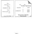
- a table of measurement data 402contains a set of PN offsets 404 and associated signal strengths 406 .
- the measurement data 402may be sent to the portable base station in response to a request for signal measurement (e.g., a TrafficChannelAssignment message).
- a request for signal measuremente.g., a TrafficChannelAssignment message.
- the PN offset of 1has been promoted to the active set alongside the PN offset 3 from the initial active set 306 .
- the promotion of PN offsets to the active set 408may force the mobile handset to measure signal strength for those PN offsets (e.g., offsets formerly listed within the remaining set 310 ).
- Various number of PN offsetsmay be promoted into the active set 408 . For example, using the TrafficChannelAssignment message, the portable base station may promote from one to five PN offsets to the active set 408 .
- the active set 408may continue to contain the PN offset of the base station that is in active communication with the mobile handset (e.g., PN offset 3 ).
- the promoted PN offsete.g., PN offset 1
- the signal strength 406is associated with a signal strength 406 of ⁇ 85 dB.
- the table 502may have been collected, for example, by a portable base station issuing TrafficChannelAssignment commands to a mobile handset.
- the table of signal strength measurements 502can be used to allocate a PN offset to a portable base station.
- the table of signal strength measurements 502could be sent within the list of PN measurements 208 (shown in FIG. 2 ) to the service manager control station 134 .
- a signal strength designating an unreachable PN offsetmay be listed within the signal strengths 506 .
- a flow chart 600represents operations in which a portable base station (e.g., portable base station 130 shown in FIG. 1 ) negotiates to receive a PN offset assignment from a service manager (e.g., service manager control station 134 shown in FIG. 1 ). Some operations may be executed by the PN offset monitor 202 (shown in FIG. 2 ).
- a portable base stationWhen a portable base station first begins broadcasting, it may be located within the broadcasting region of other fixed location and/or portable base stations. To uniquely identify itself in relation to these other base stations, the portable base station may broadcast a PN sequence at a unique PN offset.
- the local networke.g., RAN 100 shown in FIG.
- the portable base stationmay first determine a PN offset which it can broadcast without interfering with other nearby PN signals. Operations of the portable base station include receiving 602 a reserved PN offset.
- one or more reserve PN offsetsmay be coded into the portable base station by the manufacturer. For example, a different reserve PN offset may be used depending upon the geographic region the portable base station is broadcasting in. The portable base station may recognize its region, for example, by using a built-in or connected GPS device or through a user setting (e.g., start-up setting).
- the portable base stationmay begin broadcasting within the network (e.g., RAN).
- a mobile handset within the broadcast area of the portable base stationmay recognize the signal.
- Operationsinclude establishing 604 a connection with the mobile handset.
- the mobile handsetmay enter into an idle session with the portable base station.
- the operations of the portable base stationinclude receiving 606 a list of possible PN offsets from the mobile handset.
- the mobile handsetmay automatically send a list of PN offsets to the portable base station upon connection to the portable base station.
- a measurement data message 204e.g., RouteUpdate
- from the mobile handsetmay include a list of active and/or candidate PN offsets within the region of the mobile handset along with signal strengths associated with each PN offset.
- the list of PN offsets received by the portable base stationmay not include all of the PN offsets within the receiving range of the mobile handset.
- the mobile handsetmay only monitor a subset of the PN offsets associated with base stations which are broadcasting a strong enough signal to be considered as potential connection points for the mobile handset.
- Operationsinclude sending 608 a measurement command to the mobile handset including a request for signal strength information for a list of candidate PN offsets.
- the list of candidate PN offsetsmay be geographically significant. For example, only a subset of the total potential PN offset values (e.g., 512 ) may be valid within a particular geographic region. In some implementations, a set number of candidate PN offsets may be requested within a measurement command.
- a list of up to five candidate PN offsets in addition to the active PN offsetmay be promoted to the active PN offset set within a TrafficChannelAssignment message.
- Included within the measurement commandmay be a time-out value setting an amount of time to wait for a response from the candidate PN offsets and/or other information.
- Promotion to the active PN offset setmay cause the mobile handset to calculate signal strength measurements for the candidate PN offsets.
- the mobile handsetmay forward the signal strength measurements to the portable base station within a set of measurement data.
- Operationsinclude receiving 610 a list of signal strengths associated with the candidate set of PN offsets from the mobile handset.
- the portable base stationmay receive the measurement data within a RouteUpdate message from the mobile handset.
- the signal strengthsare reported in decibel format.
- the PN offset monitor 202in some implementations, may store the signal strength data received.
- Operations of the portable base stationmay include determining 612 whether or not there are remaining PN offsets. For example, a total of forty PN offset measurements may potentially be in use within the geographic region of the portable base station. If the portable base station is using the TrafficChannelAssignment message to request up to five PN offset measurements at a time, multiple measurement commands may be issued to receive information regarding the entire set of PN offsets desired. If the portable base station requires signal strength measurements for one or more remaining PN offsets, operations of the portable base station may include sending 614 a request for the signal strengths of the remaining set of PN offsets within one or more additional commands. For example, the portable base station may continue to issue measurement commands until all desired PN offsets have been measured.
- operations of the portable base stationmay include sending 616 a list of PN offsets and associated signal strengths to the service manager.
- the PN offset monitor 202may compile a list of PN offsets and their associated signal strengths as received by one or more responses to measurement commands issued to the mobile handset by the portable base station.
- the list of PN offsetsmay include only the weakest PN offset signal strengths as calculated by the mobile handset.
- the list of PN offsetsmay include the PN offsets which were unreachable and/or the PN offsets which are associated with a signal strength below a particular threshold.
- the portable base stationmay include additional information within the message to the service manager (e.g., portable base station identification, the broadcast range of the portable base station, the GPS coordinates of the portable base station, etc.).
- the service managermay use the list of PN offsets and signal strengths to assign a PN offset to the portable base station. Operations of the portable base station may further include receiving 618 a PN offset assignment from the service manager. In some implementations, the portable base station may begin to broadcast the assigned PN offset. The service manager, in some implementations, may respond with a failure to assign a PN offset. For example, the service manager may not recognize identification information sent from the portable base station.
- the portable base stationmay periodically update the PN offset assignment. For example, if the portable base station is moved to a new location, it may request a new PN offset assignment. In some implementations, the portable base station may not immediately begin broadcasting the PN offset assigned by the service manager. For example, changing to a new PN offset may cause the portable base station to disconnect any active sessions with mobile handsets. The portable base station may wait until there are no active sessions with mobile handsets to begin using the assigned PN offset.
- the techniques described aboveemploy the EV-DO air interface standard, the techniques are also applicable to other CDMA and non-CDMA air interface technologies in which an access terminal communicates with a server over a network.
- the techniques described hereincan be implemented in digital electronic circuitry, or in computer hardware, firmware, software, or in combinations of them.
- the techniquescan be implemented as a computer program product, i.e., a computer program tangibly embodied in an information carrier, e.g., in a machine-readable storage device or in a propagated signal, for execution by, or to control the operation of, data processing apparatus, e.g., a programmable processor, a computer, or multiple computers.
- a computer programcan be written in any form of programming language, including compiled or interpreted languages, and it can be deployed in any form, including as a stand-alone program or as a module, component, subroutine, or other unit suitable for use in a computing environment.
- a computer programcan be deployed to be executed on one computer or on multiple computers at one site or distributed across multiple sites and interconnected by a communication network.
- Method steps of the techniques described hereincan be performed by one or more programmable processors executing a computer program to perform functions of the invention by operating on input data and generating output. Method steps can also be performed by, and apparatus of the invention can be implemented as, special purpose logic circuitry, e.g., an FPGA (field programmable gate array) or an ASIC (application-specific integrated circuit). Modules can refer to portions of the computer program and/or the processor/special circuitry that implements that functionality.
- FPGAfield programmable gate array
- ASICapplication-specific integrated circuit
- processors suitable for the execution of a computer programinclude, by way of example, both general and special purpose microprocessors, and any one or more processors of any kind of digital computer.
- a processorwill receive instructions and data from a read-only memory or a random access memory or both.
- the essential elements of a computerare a processor for executing instructions and one or more memory devices for storing instructions and data.
- a computerwill also include, or be operatively coupled to receive data from or transfer data to, or both, one or more mass storage devices for storing data, e.g., magnetic, magneto-optical disks, or optical disks.
- Information carriers suitable for embodying computer program instructions and datainclude all forms of non-volatile memory, including by way of example semiconductor memory devices, e.g., EPROM, EEPROM, and flash memory devices; magnetic disks, e.g., internal hard disks or removable disks; magneto-optical disks; and CD-ROM and DVD-ROM disks.
- semiconductor memory devicese.g., EPROM, EEPROM, and flash memory devices
- magnetic diskse.g., internal hard disks or removable disks
- magneto-optical diskse.g., CD-ROM and DVD-ROM disks.
- the processor and the memorycan be supplemented by, or incorporated in special purpose logic circuitry.
- the techniques described hereincan be implemented on a computer having a display device, e.g., a CRT (cathode ray tube) or LCD (liquid crystal display) monitor, for displaying information to the user and a keyboard and a pointing device, e.g., a mouse or a trackball, by which the user can provide input to the computer (e.g., interact with a user interface element, for example, by clicking a button on such a pointing device).
- a display devicee.g., a CRT (cathode ray tube) or LCD (liquid crystal display) monitor
- a keyboard and a pointing devicee.g., a mouse or a trackball
- feedback provided to the usercan be any form of sensory feedback, e.g., visual feedback, auditory feedback, or tactile feedback; and input from the user can be received in any form, including acoustic, speech, or tactile input.
- the techniques described hereincan be implemented in a distributed computing system that includes a back-end component, e.g., as a data server, and/or a middleware component, e.g., an application server, and/or a front-end component, e.g., a client computer having a graphical user interface and/or a Web browser through which a user can interact with an implementation of the invention, or any combination of such back-end, middleware, or front-end components.
- the components of the systemcan be interconnected by any form or medium of digital data communication, e.g., a communication network. Examples of communication networks include a local area network (“LAN”) and a wide area network (“WAN”), e.g., the Internet, and include both wired and wireless networks.
- LANlocal area network
- WANwide area network
- the computing systemcan include clients and servers.
- a client and serverare generally remote from each other and typically interact over a communication network.
- the relationship of client and serverarises by virtue of computer programs running on the respective computers and having a client-server relationship to each other.
Landscapes
- Engineering & Computer Science (AREA)
- Computer Networks & Wireless Communication (AREA)
- Signal Processing (AREA)
- Mobile Radio Communication Systems (AREA)
Abstract
Description
Claims (25)
Priority Applications (1)
| Application Number | Priority Date | Filing Date | Title |
|---|---|---|---|
| US11/962,983US8452299B2 (en) | 2007-12-21 | 2007-12-21 | Allocating code space to base stations |
Applications Claiming Priority (1)
| Application Number | Priority Date | Filing Date | Title |
|---|---|---|---|
| US11/962,983US8452299B2 (en) | 2007-12-21 | 2007-12-21 | Allocating code space to base stations |
Publications (2)
| Publication Number | Publication Date |
|---|---|
| US20090186626A1 US20090186626A1 (en) | 2009-07-23 |
| US8452299B2true US8452299B2 (en) | 2013-05-28 |
Family
ID=40876883
Family Applications (1)
| Application Number | Title | Priority Date | Filing Date |
|---|---|---|---|
| US11/962,983Expired - Fee RelatedUS8452299B2 (en) | 2007-12-21 | 2007-12-21 | Allocating code space to base stations |
Country Status (1)
| Country | Link |
|---|---|
| US (1) | US8452299B2 (en) |
Cited By (20)
| Publication number | Priority date | Publication date | Assignee | Title |
|---|---|---|---|---|
| US20100085910A1 (en)* | 2008-10-07 | 2010-04-08 | Humblet Pierre A | Allocating communication frequencies to clusters of access points |
| US20160006659A1 (en)* | 2014-07-02 | 2016-01-07 | Samsung Electronics Co., Ltd. | Method and apparatus for inter-cell load balance in wireless communication system |
| US9237492B2 (en) | 2012-05-31 | 2016-01-12 | Commscope Technologies Llc | Providing circuit switched service |
| US9380466B2 (en) | 2013-02-07 | 2016-06-28 | Commscope Technologies Llc | Radio access networks |
| US9414399B2 (en) | 2013-02-07 | 2016-08-09 | Commscope Technologies Llc | Radio access networks |
| US9596322B2 (en) | 2014-06-11 | 2017-03-14 | Commscope Technologies Llc | Bitrate efficient transport through distributed antenna systems |
| US9936470B2 (en) | 2013-02-07 | 2018-04-03 | Commscope Technologies Llc | Radio access networks |
| US10057916B2 (en) | 2014-06-09 | 2018-08-21 | Commscope Technologies Llc | Radio access networks in which mobile devices in the same communication cell can be scheduled to use the same airlink resource |
| US10244507B2 (en) | 2013-09-24 | 2019-03-26 | Andrew Wireless Systems Gmbh | Distributed processing in a centralized radio access network |
| US10785791B1 (en) | 2015-12-07 | 2020-09-22 | Commscope Technologies Llc | Controlling data transmission in radio access networks |
| US10798667B2 (en) | 2018-06-08 | 2020-10-06 | Commscope Technologies Llc | Automatic transmit power control for radio points of a centralized radio access network that primarily provide wireless service to users located in an event area of a venue |
| US11096075B2 (en) | 2019-07-22 | 2021-08-17 | John Mezzalingua Associates, LLC | System and method for securely hosting multiple network operators in a shared spectrum access system on a single virtual base station environment |
| US11304213B2 (en) | 2018-05-16 | 2022-04-12 | Commscope Technologies Llc | Dynamic uplink reuse in a C-RAN |
| US11395259B2 (en) | 2018-05-16 | 2022-07-19 | Commscope Technologies Llc | Downlink multicast for efficient front-haul utilization in a C-RAN |
| US11627497B2 (en) | 2018-09-04 | 2023-04-11 | Commscope Technologies Llc | Front-haul rate reduction for use in a centralized radio access network |
| US11678358B2 (en) | 2017-10-03 | 2023-06-13 | Commscope Technologies Llc | Dynamic downlink reuse in a C-RAN |
| US12016084B2 (en) | 2018-01-04 | 2024-06-18 | Commscope Technologies Llc | Management of a split physical layer in a radio area network |
| US12021672B2 (en) | 2015-03-11 | 2024-06-25 | Commscope Technologies Llc | Remote radio unit using adaptive compression in a distributed radio access network |
| US12219510B2 (en) | 2018-08-29 | 2025-02-04 | Commscope Technologies Llc | Clock synchronization in a centralized radio access network having multiple controllers |
| US12245176B2 (en) | 2016-07-18 | 2025-03-04 | Commscope Technologies Llc | Device for fronthaul communication between a baseband unit and a remote unit of a radio access network |
Families Citing this family (49)
| Publication number | Priority date | Publication date | Assignee | Title |
|---|---|---|---|---|
| US8195187B2 (en) | 2001-06-25 | 2012-06-05 | Airvana Network Solutions, Inc. | Radio network control |
| US7603127B2 (en)* | 2001-10-12 | 2009-10-13 | Airvana, Inc. | Boosting a signal-to-interference ratio of a mobile station |
| WO2006010957A2 (en)* | 2004-07-30 | 2006-02-02 | Andrew Richardson | Signal transmission method from a local network node |
| WO2006010953A2 (en)* | 2004-07-30 | 2006-02-02 | Andrew Richardson | A local network node |
| US8290527B2 (en)* | 2004-07-30 | 2012-10-16 | Airvana, Corp. | Power control in a local network node (LNN) |
| US7539158B2 (en) | 2004-11-08 | 2009-05-26 | Lemko Corporation | System, method and device for providing communications using a distributed mobile architecture |
| US20070140218A1 (en)* | 2005-12-16 | 2007-06-21 | Nair Girish R | Managing backhaul connections in radio access networks |
| US7801487B2 (en) | 2005-12-29 | 2010-09-21 | Airvana, Inc. | Detection of radio frequency interference in wireless communication systems |
| US7856233B2 (en) | 2006-03-30 | 2010-12-21 | Lemko Corporation | System, method, and device for providing communications using a distributed mobile architecture |
| US8224322B2 (en) | 2006-06-12 | 2012-07-17 | Lemko Corporation | Roaming mobile subscriber registration in a distributed mobile architecture |
| US8085696B2 (en) | 2006-07-14 | 2011-12-27 | Airvana Networks Solutions, Inc. | Dynamic modification of route update protocols |
| US8023439B2 (en)* | 2006-11-20 | 2011-09-20 | Airvana Network Solutions, Inc. | Multicast flow distribution |
| US8130686B2 (en)* | 2006-11-20 | 2012-03-06 | Airvana Network Solutions, Inc. | Multicasting push-to-media content |
| US7730189B2 (en)* | 2006-11-22 | 2010-06-01 | Airvana, Inc. | Network-initiated session recovery |
| US8639247B2 (en)* | 2006-12-12 | 2014-01-28 | Ericsson Evdo Inc. | Access terminal session authentication |
| US8676197B2 (en) | 2006-12-13 | 2014-03-18 | Lemko Corporation | System, method, and device to control wireless communications |
| US8176327B2 (en) | 2006-12-27 | 2012-05-08 | Airvana, Corp. | Authentication protocol |
| US7926098B2 (en) | 2006-12-29 | 2011-04-12 | Airvana, Corp. | Handoff of a secure connection among gateways |
| GB0706781D0 (en)* | 2007-04-05 | 2007-05-16 | Vodafone Plc | Telecommunications networks and devices |
| US8781483B2 (en)* | 2007-04-13 | 2014-07-15 | Airvana Lp | Controlling access to private access points for wireless networking |
| US8400989B2 (en)* | 2007-04-13 | 2013-03-19 | Airvana Llc | Activating private access points for wireless networking |
| US8543139B2 (en)* | 2007-08-03 | 2013-09-24 | Airvana Llc | Distributed network |
| US8059614B2 (en)* | 2007-08-31 | 2011-11-15 | Samsung Electronics Co., Ltd. | Pseudorandom noise selection method for mobile communication sites |
| US8358623B2 (en)* | 2007-11-06 | 2013-01-22 | Airvana Network Solutions, Inc. | Active handoffs in a network |
| US8355727B2 (en) | 2007-12-19 | 2013-01-15 | Airvana, Corp. | Proximity detection in a network |
| US7983672B2 (en) | 2007-12-19 | 2011-07-19 | Airvana, Corp. | Managing communications with private access points in wireless networks |
| US8452299B2 (en) | 2007-12-21 | 2013-05-28 | Airvana Llc | Allocating code space to base stations |
| US8615593B2 (en)* | 2007-12-21 | 2013-12-24 | Airvana Llc | Providing zone indications for wireless networking |
| US20090168766A1 (en)* | 2007-12-28 | 2009-07-02 | Vedat Eyuboglu | Inter-Technology Bridging Over Access Points |
| US8060058B2 (en) | 2007-12-28 | 2011-11-15 | Airvana, Corp. | Secure mobile base station connections |
| US8046420B2 (en) | 2008-04-23 | 2011-10-25 | Lemko Corporation | System and method to control wireless communications |
| US8340667B2 (en) | 2008-06-26 | 2012-12-25 | Lemko Corporation | System and method to control wireless communications |
| US8706105B2 (en) | 2008-06-27 | 2014-04-22 | Lemko Corporation | Fault tolerant distributed mobile architecture |
| US8107409B2 (en)* | 2008-07-11 | 2012-01-31 | Lemko Corporation | OAMP for distributed mobile architecture |
| US7855988B2 (en) | 2008-07-14 | 2010-12-21 | Lemko Corporation | System, method, and device for routing calls using a distributed mobile architecture |
| US8295256B2 (en)* | 2008-08-29 | 2012-10-23 | Airvana, Corp. | Private access point beacon signals in wireless networks |
| US8229397B2 (en) | 2008-09-23 | 2012-07-24 | Airvana, Corp. | Access terminal authorization at private access points in wireless networks |
| US7979066B2 (en) | 2008-09-25 | 2011-07-12 | Lemko Corporation | Multiple IMSI connections |
| US7995493B2 (en) | 2008-12-23 | 2011-08-09 | Airvana, Corp. | Estimating bandwidth in communication networks |
| US8805371B2 (en)* | 2009-03-17 | 2014-08-12 | Airvana Lp | Identifying hand-over targets in lightly coordinated networks |
| WO2010129897A1 (en) | 2009-05-07 | 2010-11-11 | Airvana Network Solutions, Inc. | Wireless network inter-technology handoffs |
| US8718697B2 (en)* | 2009-10-07 | 2014-05-06 | Airvana Lp | Mitigating interference using cooperative scheduling |
| US8223711B1 (en)* | 2009-10-27 | 2012-07-17 | Sprint Communications Company L.P. | Efficient message delivery to wireless communication devices |
| US8340636B2 (en)* | 2009-11-30 | 2012-12-25 | Airvana Llc | Determining if an access terminal is authorized to use an access point |
| CN101895990B (en)* | 2010-06-13 | 2013-04-24 | 华为技术有限公司 | Method, device and system for wireless access |
| KR101782643B1 (en)* | 2010-12-15 | 2017-09-28 | 한국전자통신연구원 | Apparatus and method for tracking position of fixed node |
| CN105684515A (en)* | 2014-06-10 | 2016-06-15 | 奇点新源国际技术开发(北京)有限公司 | Mobile station, base station, wireless communication system and communication method |
| WO2016162854A1 (en)* | 2015-04-10 | 2016-10-13 | Telefonaktiebolaget Lm Ericsson (Publ) | Preventing offload return |
| US10693713B1 (en)* | 2019-02-22 | 2020-06-23 | At&T Intellectual Property I, L.P. | Method and apparatus for providing service coverage with a measurement-based dynamic threshold adjustment |
Citations (78)
| Publication number | Priority date | Publication date | Assignee | Title |
|---|---|---|---|---|
| US20020196749A1 (en) | 2001-06-25 | 2002-12-26 | Eyuboglu M. Vedat | Radio network control |
| US20030100311A1 (en) | 2001-10-12 | 2003-05-29 | Sae-Young Chung | Boosting a signal-to-interference ratio of a mobile station |
| US6711144B1 (en) | 2000-09-15 | 2004-03-23 | Airvana, Inc. | Multi-user communication of voice and data |
| US6731618B1 (en) | 2000-10-20 | 2004-05-04 | Airvana, Inc. | Coding for multi-user communication |
| US6731941B2 (en)* | 2000-03-30 | 2004-05-04 | Huyndai Electronics Industries Co., Inc. | Method for locating mobile station based on power-related message of base transceiver station |
| US6741862B2 (en) | 2001-02-07 | 2004-05-25 | Airvana, Inc. | Enhanced reverse-link rate control in wireless communication |
| US6781999B2 (en) | 2001-07-23 | 2004-08-24 | Airvana, Inc. | Broadcasting and multicasting in wireless communication |
| US20050138671A1 (en)* | 2003-12-22 | 2005-06-23 | Love Robert T. | Apparatus and method for adaptive broadcast transmission |
| US20050213555A1 (en) | 2001-06-25 | 2005-09-29 | Vedat Eyuboglu | Radio network control |
| US20050245279A1 (en) | 2004-04-28 | 2005-11-03 | Sepehr Mehrabanzad | Reverse link power control |
| US20050243749A1 (en) | 2004-04-28 | 2005-11-03 | Sepehr Mehrabanzad | Reverse link power control |
| US20060067422A1 (en) | 2004-09-30 | 2006-03-30 | Sae-Young Chung | Modulation for broadcasting from multiple transmitters |
| US20060067451A1 (en) | 2004-09-30 | 2006-03-30 | Pollman Michael D | Providing global positioning system timing signals to remote cellular base stations |
| US20060126509A1 (en) | 2004-12-09 | 2006-06-15 | Firas Abi-Nassif | Traffic management in a wireless data network |
| US20060159045A1 (en) | 2005-01-18 | 2006-07-20 | Satish Ananthaiyer | Reverse link rate and stability control |
| US20060240782A1 (en) | 2005-04-26 | 2006-10-26 | Pollman Michael D | Measuring interference in radio networks |
| US20060294241A1 (en) | 2005-06-24 | 2006-12-28 | Sanjay Cherian | Preserving sessions in a wireless network |
| US20060291420A1 (en) | 2005-06-27 | 2006-12-28 | Dennis Ng | Network-initiated dormant handoffs |
| US20070026884A1 (en) | 2005-07-28 | 2007-02-01 | Prashanth Rao | Controlling usage capacity in a radio access network |
| US20070058628A1 (en) | 2005-09-15 | 2007-03-15 | Palnati Prasasth R | Broadcasting in wireless systems |
| US7200391B2 (en) | 2002-12-06 | 2007-04-03 | Airvana, Inc. | Capacity enhancement schemes for forward and reverse links of distributed cellular base stations |
| US20070077948A1 (en) | 2005-10-04 | 2007-04-05 | Vivek Sharma | Non-circular paging areas |
| US20070115896A1 (en) | 2005-11-18 | 2007-05-24 | Philip To | Resource allocation in a radio access network |
| US20070140218A1 (en) | 2005-12-16 | 2007-06-21 | Nair Girish R | Managing backhaul connections in radio access networks |
| US20070140172A1 (en) | 2005-12-16 | 2007-06-21 | Deepak Garg | Radio network control |
| US20070140184A1 (en) | 2005-12-16 | 2007-06-21 | Deepak Garg | Radio frequency dragging prevention |
| US20070140185A1 (en) | 2005-12-16 | 2007-06-21 | Deepak Garg | Radio network communication |
| US20070155329A1 (en) | 2005-12-29 | 2007-07-05 | Sepehr Mehrabanzad | Detection of radio frequency interference in wireless communication systems |
| US20070220573A1 (en) | 2006-03-20 | 2007-09-20 | Chiussi Fabio M | Unicasting and multicasting multimedia services |
| US7277446B1 (en) | 2000-11-02 | 2007-10-02 | Airvana, Inc. | Communication of digital data over a wireless transmission medium |
| US20070230419A1 (en) | 2006-03-31 | 2007-10-04 | Sundar Raman | QoS signaling to support fairness |
| US20070238476A1 (en) | 2006-03-28 | 2007-10-11 | Vivek Sharma | Managing page cycle periods of access terminals |
| US20070238442A1 (en) | 2006-03-31 | 2007-10-11 | Amit Mate | Signaling for push-to-talk |
| US20070242648A1 (en) | 2006-04-12 | 2007-10-18 | Deepak Garg | Managing dormant handoffs in radio access networks |
| US20070248042A1 (en) | 2006-04-19 | 2007-10-25 | Gopal Harikumar | Channel assignment in wireless communication |
| US7299278B2 (en) | 2002-01-16 | 2007-11-20 | Airvana, Inc. | Managing network faults |
| US20080003988A1 (en) | 2004-07-30 | 2008-01-03 | Andrew Richardson | Local Network Node |
| US20080013488A1 (en) | 2006-07-14 | 2008-01-17 | Deepak Garg | Dynamic modification of route update protocols |
| US20080065752A1 (en) | 2006-09-07 | 2008-03-13 | Ch Ng Shi Baw | Provisioning private access points for wireless networking |
| US20080062925A1 (en) | 2006-09-07 | 2008-03-13 | Amit Mate | Controlling reverse link interference in private access points for wireless networking |
| US20080069020A1 (en) | 2004-07-30 | 2008-03-20 | Andrew Richardson | Signal Transmission Method from a Local Network Node |
| US20080069028A1 (en) | 2004-07-30 | 2008-03-20 | Andrew Richardson | Power Control in a Local Network Node (Lln) |
| US20080076398A1 (en) | 2006-09-07 | 2008-03-27 | Amit Mate | Configuring preferred user zone lists for private access points for wireless networking |
| US20080107215A1 (en)* | 2005-07-05 | 2008-05-08 | Keiji Nibe | Reception quality calculation method, reception quality calculation apparatus, and communication apparatus |
| US20080119172A1 (en) | 2006-11-20 | 2008-05-22 | Rao Roshan M | Multicasting Push-To-Media Content |
| US20080120417A1 (en) | 2006-11-22 | 2008-05-22 | Gopal Harikumar | Network-Initiated Session Recovery |
| US20080117842A1 (en) | 2006-11-20 | 2008-05-22 | Rao Roshan M | Multicast Flow Distribution |
| US20080139203A1 (en) | 2006-12-12 | 2008-06-12 | Dennis Ng | Access Terminal Session Authentication |
| US20080146232A1 (en) | 2006-12-19 | 2008-06-19 | Douglas Norman Knisely | Neighbor list provision in a communication network |
| US20080151843A1 (en) | 2006-12-20 | 2008-06-26 | Ravi Valmikam | Communication group configuration in a network |
| US20080162926A1 (en) | 2006-12-27 | 2008-07-03 | Jay Xiong | Authentication protocol |
| US20080159236A1 (en) | 2006-12-28 | 2008-07-03 | Airvana, Inc. | Assigning code space to portable base stations |
| US20080162924A1 (en) | 2006-12-29 | 2008-07-03 | Airvana, Inc. | Handoff of a secure connection among gateways |
| US20080205342A1 (en)* | 2007-02-08 | 2008-08-28 | Radhakrishnan Shaji E | System and method for handoffs between technologies |
| US20080254792A1 (en) | 2007-04-13 | 2008-10-16 | Ch Ng Shi Baw | Controlling Access To Private Access Points For Wireless Networking |
| US20080253550A1 (en) | 2007-04-13 | 2008-10-16 | Ch Ng Shi Baw | Activating Private Access Points For Wireless Networking |
| US20090034440A1 (en) | 2007-08-03 | 2009-02-05 | Airvana, Inc. | Distributed network |
| GB2452688A (en) | 2006-10-07 | 2009-03-18 | Andrew Richardson | In-C Device to Core Network Interface Specification |
| US20090082020A1 (en) | 2007-09-24 | 2009-03-26 | Ch Ng Shi Baw | Selecting embedded cells in wireless networks |
| US20090088155A1 (en) | 2007-10-02 | 2009-04-02 | Woojune Kim | Wireless control of access points |
| US20090116445A1 (en) | 2007-11-06 | 2009-05-07 | Airvana, Inc. | Active handoffs in a network |
| US20090156165A1 (en) | 2007-12-18 | 2009-06-18 | Balaji Raghothaman | Attracting Access Terminals |
| US20090154447A1 (en) | 2007-12-18 | 2009-06-18 | Humblet Pierre A | Absolute time recovery |
| US20090156195A1 (en) | 2007-12-18 | 2009-06-18 | Humblet Pierre A | Obtaining time information in a cellular network |
| US20090156218A1 (en) | 2007-12-13 | 2009-06-18 | Airvana, Inc. | Handing off active connections |
| US20090163238A1 (en) | 2007-12-21 | 2009-06-25 | Prashanth Rao | Adjusting Wireless Signal Transmission Power |
| US20090164547A1 (en) | 2007-12-21 | 2009-06-25 | Ch Ng Shi Baw | Providing zone indications for wireless networking |
| US20090163216A1 (en) | 2007-12-19 | 2009-06-25 | Minh Hoang | Proximity detection in a network |
| US20090163202A1 (en) | 2007-12-19 | 2009-06-25 | Humblet Pierre A | Managing communications with private access points in wireless networks |
| US20090168788A1 (en) | 2007-12-31 | 2009-07-02 | Minsh Den | Network address translation for tunnel mobility |
| US20090170440A1 (en) | 2007-12-31 | 2009-07-02 | Airvana, Inc. | Interference Mitigation in Wireless Networks |
| US20090170520A1 (en) | 2007-12-31 | 2009-07-02 | Kenneth Jones | Adaptation of portable base stations into cellular networks |
| US20090172169A1 (en) | 2007-12-28 | 2009-07-02 | Suresh Ramaswamy | Secure proxies for flat networks |
| US20090170475A1 (en) | 2007-12-28 | 2009-07-02 | Airvana, Inc. | Secure Mobile Base Station Connections |
| US20090172397A1 (en) | 2007-12-31 | 2009-07-02 | Woojune Kim | IMS Security for Femtocells |
| US20090170547A1 (en) | 2007-12-27 | 2009-07-02 | Balaji Raghothaman | Interference mitigation in wireless networks |
| US20090168766A1 (en) | 2007-12-28 | 2009-07-02 | Vedat Eyuboglu | Inter-Technology Bridging Over Access Points |
| US20090186626A1 (en) | 2007-12-21 | 2009-07-23 | Airvana, Inc. | Allocating Code Space to Base Stations |
Family Cites Families (1)
| Publication number | Priority date | Publication date | Assignee | Title |
|---|---|---|---|---|
| US7003795B2 (en)* | 2001-06-26 | 2006-02-21 | Digeo, Inc. | Webcam-based interface for initiating two-way video communication |
- 2007
- 2007-12-21USUS11/962,983patent/US8452299B2/ennot_activeExpired - Fee Related
Patent Citations (83)
| Publication number | Priority date | Publication date | Assignee | Title |
|---|---|---|---|---|
| US6731941B2 (en)* | 2000-03-30 | 2004-05-04 | Huyndai Electronics Industries Co., Inc. | Method for locating mobile station based on power-related message of base transceiver station |
| US6711144B1 (en) | 2000-09-15 | 2004-03-23 | Airvana, Inc. | Multi-user communication of voice and data |
| US6731618B1 (en) | 2000-10-20 | 2004-05-04 | Airvana, Inc. | Coding for multi-user communication |
| US7277446B1 (en) | 2000-11-02 | 2007-10-02 | Airvana, Inc. | Communication of digital data over a wireless transmission medium |
| US6741862B2 (en) | 2001-02-07 | 2004-05-25 | Airvana, Inc. | Enhanced reverse-link rate control in wireless communication |
| US20020196749A1 (en) | 2001-06-25 | 2002-12-26 | Eyuboglu M. Vedat | Radio network control |
| US20070097916A1 (en) | 2001-06-25 | 2007-05-03 | Airvana, Inc., A Massachusetts Corporation | Radio network control |
| US7170871B2 (en) | 2001-06-25 | 2007-01-30 | Airvana, Inc. | Radio network control |
| US20050213555A1 (en) | 2001-06-25 | 2005-09-29 | Vedat Eyuboglu | Radio network control |
| US6781999B2 (en) | 2001-07-23 | 2004-08-24 | Airvana, Inc. | Broadcasting and multicasting in wireless communication |
| US7242958B2 (en) | 2001-10-12 | 2007-07-10 | Airvana, Inc. | Boosting a signal-to-interference ratio of a mobile station |
| US20030100311A1 (en) | 2001-10-12 | 2003-05-29 | Sae-Young Chung | Boosting a signal-to-interference ratio of a mobile station |
| US7299278B2 (en) | 2002-01-16 | 2007-11-20 | Airvana, Inc. | Managing network faults |
| US7200391B2 (en) | 2002-12-06 | 2007-04-03 | Airvana, Inc. | Capacity enhancement schemes for forward and reverse links of distributed cellular base stations |
| US20050138671A1 (en)* | 2003-12-22 | 2005-06-23 | Love Robert T. | Apparatus and method for adaptive broadcast transmission |
| US20050245279A1 (en) | 2004-04-28 | 2005-11-03 | Sepehr Mehrabanzad | Reverse link power control |
| US20050243749A1 (en) | 2004-04-28 | 2005-11-03 | Sepehr Mehrabanzad | Reverse link power control |
| US20080069028A1 (en) | 2004-07-30 | 2008-03-20 | Andrew Richardson | Power Control in a Local Network Node (Lln) |
| US20080003988A1 (en) | 2004-07-30 | 2008-01-03 | Andrew Richardson | Local Network Node |
| US20080069020A1 (en) | 2004-07-30 | 2008-03-20 | Andrew Richardson | Signal Transmission Method from a Local Network Node |
| US20060067422A1 (en) | 2004-09-30 | 2006-03-30 | Sae-Young Chung | Modulation for broadcasting from multiple transmitters |
| US20060067451A1 (en) | 2004-09-30 | 2006-03-30 | Pollman Michael D | Providing global positioning system timing signals to remote cellular base stations |
| US7558356B2 (en) | 2004-09-30 | 2009-07-07 | Airvana, Inc. | Providing global positioning system (GPS) timing signals to remote cellular base stations |
| US20060126509A1 (en) | 2004-12-09 | 2006-06-15 | Firas Abi-Nassif | Traffic management in a wireless data network |
| US20060159045A1 (en) | 2005-01-18 | 2006-07-20 | Satish Ananthaiyer | Reverse link rate and stability control |
| US20060240782A1 (en) | 2005-04-26 | 2006-10-26 | Pollman Michael D | Measuring interference in radio networks |
| US20060294241A1 (en) | 2005-06-24 | 2006-12-28 | Sanjay Cherian | Preserving sessions in a wireless network |
| US20060291420A1 (en) | 2005-06-27 | 2006-12-28 | Dennis Ng | Network-initiated dormant handoffs |
| US20080107215A1 (en)* | 2005-07-05 | 2008-05-08 | Keiji Nibe | Reception quality calculation method, reception quality calculation apparatus, and communication apparatus |
| US20070026884A1 (en) | 2005-07-28 | 2007-02-01 | Prashanth Rao | Controlling usage capacity in a radio access network |
| US20070058628A1 (en) | 2005-09-15 | 2007-03-15 | Palnati Prasasth R | Broadcasting in wireless systems |
| US20070077948A1 (en) | 2005-10-04 | 2007-04-05 | Vivek Sharma | Non-circular paging areas |
| US20070115896A1 (en) | 2005-11-18 | 2007-05-24 | Philip To | Resource allocation in a radio access network |
| US7558588B2 (en) | 2005-11-18 | 2009-07-07 | Airvana, Inc. | Resource allocation in a radio access network |
| US20070140185A1 (en) | 2005-12-16 | 2007-06-21 | Deepak Garg | Radio network communication |
| US20070140218A1 (en) | 2005-12-16 | 2007-06-21 | Nair Girish R | Managing backhaul connections in radio access networks |
| US20070140172A1 (en) | 2005-12-16 | 2007-06-21 | Deepak Garg | Radio network control |
| US20070140184A1 (en) | 2005-12-16 | 2007-06-21 | Deepak Garg | Radio frequency dragging prevention |
| US20070155329A1 (en) | 2005-12-29 | 2007-07-05 | Sepehr Mehrabanzad | Detection of radio frequency interference in wireless communication systems |
| US20070220573A1 (en) | 2006-03-20 | 2007-09-20 | Chiussi Fabio M | Unicasting and multicasting multimedia services |
| US20070238476A1 (en) | 2006-03-28 | 2007-10-11 | Vivek Sharma | Managing page cycle periods of access terminals |
| US20070238442A1 (en) | 2006-03-31 | 2007-10-11 | Amit Mate | Signaling for push-to-talk |
| US20070230419A1 (en) | 2006-03-31 | 2007-10-04 | Sundar Raman | QoS signaling to support fairness |
| US20070242648A1 (en) | 2006-04-12 | 2007-10-18 | Deepak Garg | Managing dormant handoffs in radio access networks |
| US20070248042A1 (en) | 2006-04-19 | 2007-10-25 | Gopal Harikumar | Channel assignment in wireless communication |
| US20080013488A1 (en) | 2006-07-14 | 2008-01-17 | Deepak Garg | Dynamic modification of route update protocols |
| US20080062925A1 (en) | 2006-09-07 | 2008-03-13 | Amit Mate | Controlling reverse link interference in private access points for wireless networking |
| US20080076398A1 (en) | 2006-09-07 | 2008-03-27 | Amit Mate | Configuring preferred user zone lists for private access points for wireless networking |
| US20080065752A1 (en) | 2006-09-07 | 2008-03-13 | Ch Ng Shi Baw | Provisioning private access points for wireless networking |
| GB2452688A (en) | 2006-10-07 | 2009-03-18 | Andrew Richardson | In-C Device to Core Network Interface Specification |
| US20080119172A1 (en) | 2006-11-20 | 2008-05-22 | Rao Roshan M | Multicasting Push-To-Media Content |
| US20080117842A1 (en) | 2006-11-20 | 2008-05-22 | Rao Roshan M | Multicast Flow Distribution |
| US20080120417A1 (en) | 2006-11-22 | 2008-05-22 | Gopal Harikumar | Network-Initiated Session Recovery |
| US20080139203A1 (en) | 2006-12-12 | 2008-06-12 | Dennis Ng | Access Terminal Session Authentication |
| US20080146232A1 (en) | 2006-12-19 | 2008-06-19 | Douglas Norman Knisely | Neighbor list provision in a communication network |
| US20080151843A1 (en) | 2006-12-20 | 2008-06-26 | Ravi Valmikam | Communication group configuration in a network |
| US20080162926A1 (en) | 2006-12-27 | 2008-07-03 | Jay Xiong | Authentication protocol |
| US20080159236A1 (en) | 2006-12-28 | 2008-07-03 | Airvana, Inc. | Assigning code space to portable base stations |
| US20080162924A1 (en) | 2006-12-29 | 2008-07-03 | Airvana, Inc. | Handoff of a secure connection among gateways |
| US20080205342A1 (en)* | 2007-02-08 | 2008-08-28 | Radhakrishnan Shaji E | System and method for handoffs between technologies |
| US20080253550A1 (en) | 2007-04-13 | 2008-10-16 | Ch Ng Shi Baw | Activating Private Access Points For Wireless Networking |
| US20080254792A1 (en) | 2007-04-13 | 2008-10-16 | Ch Ng Shi Baw | Controlling Access To Private Access Points For Wireless Networking |
| US20090034440A1 (en) | 2007-08-03 | 2009-02-05 | Airvana, Inc. | Distributed network |
| US20090082020A1 (en) | 2007-09-24 | 2009-03-26 | Ch Ng Shi Baw | Selecting embedded cells in wireless networks |
| US20090088155A1 (en) | 2007-10-02 | 2009-04-02 | Woojune Kim | Wireless control of access points |
| US20090116445A1 (en) | 2007-11-06 | 2009-05-07 | Airvana, Inc. | Active handoffs in a network |
| US20090156218A1 (en) | 2007-12-13 | 2009-06-18 | Airvana, Inc. | Handing off active connections |
| US20090156165A1 (en) | 2007-12-18 | 2009-06-18 | Balaji Raghothaman | Attracting Access Terminals |
| US20090154447A1 (en) | 2007-12-18 | 2009-06-18 | Humblet Pierre A | Absolute time recovery |
| US20090156195A1 (en) | 2007-12-18 | 2009-06-18 | Humblet Pierre A | Obtaining time information in a cellular network |
| US20090163216A1 (en) | 2007-12-19 | 2009-06-25 | Minh Hoang | Proximity detection in a network |
| US20090163202A1 (en) | 2007-12-19 | 2009-06-25 | Humblet Pierre A | Managing communications with private access points in wireless networks |
| US20090164547A1 (en) | 2007-12-21 | 2009-06-25 | Ch Ng Shi Baw | Providing zone indications for wireless networking |
| US20090186626A1 (en) | 2007-12-21 | 2009-07-23 | Airvana, Inc. | Allocating Code Space to Base Stations |
| US20090163238A1 (en) | 2007-12-21 | 2009-06-25 | Prashanth Rao | Adjusting Wireless Signal Transmission Power |
| US20090170547A1 (en) | 2007-12-27 | 2009-07-02 | Balaji Raghothaman | Interference mitigation in wireless networks |
| US20090168766A1 (en) | 2007-12-28 | 2009-07-02 | Vedat Eyuboglu | Inter-Technology Bridging Over Access Points |
| US20090172169A1 (en) | 2007-12-28 | 2009-07-02 | Suresh Ramaswamy | Secure proxies for flat networks |
| US20090170475A1 (en) | 2007-12-28 | 2009-07-02 | Airvana, Inc. | Secure Mobile Base Station Connections |
| US20090170520A1 (en) | 2007-12-31 | 2009-07-02 | Kenneth Jones | Adaptation of portable base stations into cellular networks |
| US20090172397A1 (en) | 2007-12-31 | 2009-07-02 | Woojune Kim | IMS Security for Femtocells |
| US20090170440A1 (en) | 2007-12-31 | 2009-07-02 | Airvana, Inc. | Interference Mitigation in Wireless Networks |
| US20090168788A1 (en) | 2007-12-31 | 2009-07-02 | Minsh Den | Network address translation for tunnel mobility |
Non-Patent Citations (7)
| Title |
|---|
| 3rd Generation Partnership Project 2 "3GPP2", "cdma2000 1X Layer 3 Specification", C.S0005-A, version 5, Jul. 2001 (1696 pages). |
| 3rd Generation Partnership Project 2 "3GPP2", "cdma2000 1X Layer 3 Specification", C.S0005-A, version 6, Addendum A, Feb. 2002 (1664 pages). |
| 3rd Generation Partnership Project 2 "3GPP2", "cdma2000 High Rate Packet Data Interface Specification", C.S0024, version 2, Oct. 27, 2000 (441 pages). |
| 3rd Generation Partnership Project 2 "3GPP2", "cdma2000 High Rate Packet Data Interface Specification", C.S0024, version 4, Oct. 25, 2002 (548 pages). |
| 3rd Generation Partnership Project 2 "3GPP2", "cdma2000 High Rate Packet Data Interface Specification", C.S0024-A, version 2, Jul. 2005 (1227 pages). |
| 3rd Generation Partnership Project 2 "3GPP2", "cdma2000 High Rate Packet Data Interface Specification", C.S0024-B, version 1, Apr. 2006 (1623 pages). |
| 3rd Generation Partnership Project 2 "3GPP2", "cdma2000 High Rate Packet Data Interface Specification", C.S0024-B, version 2, Mar. 2007 (1627 pages). |
Cited By (49)
| Publication number | Priority date | Publication date | Assignee | Title |
|---|---|---|---|---|
| US8942136B2 (en) | 2008-10-07 | 2015-01-27 | Airvana Lp | Allocating communication frequencies to clusters of access points |
| US20100085910A1 (en)* | 2008-10-07 | 2010-04-08 | Humblet Pierre A | Allocating communication frequencies to clusters of access points |
| US9237492B2 (en) | 2012-05-31 | 2016-01-12 | Commscope Technologies Llc | Providing circuit switched service |
| US11102663B2 (en) | 2013-02-07 | 2021-08-24 | Commscope Technologies Llc | Radio access networks |
| US10142858B2 (en) | 2013-02-07 | 2018-11-27 | Commscope Technologies Llc | Radio access networks |
| US9414399B2 (en) | 2013-02-07 | 2016-08-09 | Commscope Technologies Llc | Radio access networks |
| US11445455B2 (en) | 2013-02-07 | 2022-09-13 | Commscope Technologies Llc | Radio access networks |
| US11706640B2 (en) | 2013-02-07 | 2023-07-18 | Commscope Technologies Llc | Radio access networks |
| US9936470B2 (en) | 2013-02-07 | 2018-04-03 | Commscope Technologies Llc | Radio access networks |
| US12047933B2 (en) | 2013-02-07 | 2024-07-23 | Commscope Technologies Llc | Radio access networks |
| US11700602B2 (en) | 2013-02-07 | 2023-07-11 | Commscope Technologies Llc | Radio access networks |
| US10064072B2 (en) | 2013-02-07 | 2018-08-28 | Commscope Technologies Llc | Radio access networks |
| US11729758B2 (en) | 2013-02-07 | 2023-08-15 | Commscope Technologies Llc | Radio access networks |
| US12156048B2 (en) | 2013-02-07 | 2024-11-26 | Commscope Technologies Llc | Radio access networks |
| US10292175B2 (en) | 2013-02-07 | 2019-05-14 | Commscope Technologies Llc | Radio access networks |
| US11122447B2 (en) | 2013-02-07 | 2021-09-14 | Commscope Technologies Llc | Radio access networks |
| US10455597B2 (en) | 2013-02-07 | 2019-10-22 | Commscope Technologies Llc | Radio access networks |
| US9380466B2 (en) | 2013-02-07 | 2016-06-28 | Commscope Technologies Llc | Radio access networks |
| US12418907B2 (en) | 2013-02-07 | 2025-09-16 | Outdoor Wireless Networks LLC | Radio access networks |
| US10764846B2 (en) | 2013-02-07 | 2020-09-01 | Commscope Technologies Llc | Radio access networks |
| US12170973B2 (en) | 2013-02-07 | 2024-12-17 | Commscope Technologies Llc | Radio access networks |
| US10244507B2 (en) | 2013-09-24 | 2019-03-26 | Andrew Wireless Systems Gmbh | Distributed processing in a centralized radio access network |
| US10057916B2 (en) | 2014-06-09 | 2018-08-21 | Commscope Technologies Llc | Radio access networks in which mobile devices in the same communication cell can be scheduled to use the same airlink resource |
| US11974269B2 (en) | 2014-06-09 | 2024-04-30 | Commscope Technologies Llc | Radio access networks |
| US11082997B2 (en) | 2014-06-09 | 2021-08-03 | Commscope Technologies Llc | Radio access networks in which mobile devices can be scheduled to use the same time-frequency resource |
| US10536959B2 (en) | 2014-06-09 | 2020-01-14 | Commscope Technologies Llc | Radio access networks in which remote units are configured to perform at least some baseband processing |
| US10333591B2 (en) | 2014-06-11 | 2019-06-25 | Commscope Technologies Llc | Bitrate efficient transport through distributed antenna systems |
| US9954584B2 (en) | 2014-06-11 | 2018-04-24 | Commscope Technologies Llc | Bitrate efficient transport through distributed antenna systems |
| US9686379B2 (en) | 2014-06-11 | 2017-06-20 | Commscope Technologies Llc | Bitrate efficient transport through distributed antenna systems |
| US9596322B2 (en) | 2014-06-11 | 2017-03-14 | Commscope Technologies Llc | Bitrate efficient transport through distributed antenna systems |
| US10547550B2 (en)* | 2014-07-02 | 2020-01-28 | Samsung Electronics Co., Ltd. | Method and apparatus for inter-cell load balance in wireless communication system |
| US11463363B2 (en) | 2014-07-02 | 2022-10-04 | Samsung Electronics Co., Ltd. | Method and apparatus for inter-cell load balance in wireless communication system |
| US20160006659A1 (en)* | 2014-07-02 | 2016-01-07 | Samsung Electronics Co., Ltd. | Method and apparatus for inter-cell load balance in wireless communication system |
| US12021672B2 (en) | 2015-03-11 | 2024-06-25 | Commscope Technologies Llc | Remote radio unit using adaptive compression in a distributed radio access network |
| US10785791B1 (en) | 2015-12-07 | 2020-09-22 | Commscope Technologies Llc | Controlling data transmission in radio access networks |
| US12245176B2 (en) | 2016-07-18 | 2025-03-04 | Commscope Technologies Llc | Device for fronthaul communication between a baseband unit and a remote unit of a radio access network |
| US12426075B2 (en) | 2017-10-03 | 2025-09-23 | Outdoor Wireless Networks LLC | Dynamic downlink reuse in a C-RAN |
| US11678358B2 (en) | 2017-10-03 | 2023-06-13 | Commscope Technologies Llc | Dynamic downlink reuse in a C-RAN |
| US12016084B2 (en) | 2018-01-04 | 2024-06-18 | Commscope Technologies Llc | Management of a split physical layer in a radio area network |
| US11395259B2 (en) | 2018-05-16 | 2022-07-19 | Commscope Technologies Llc | Downlink multicast for efficient front-haul utilization in a C-RAN |
| US11304213B2 (en) | 2018-05-16 | 2022-04-12 | Commscope Technologies Llc | Dynamic uplink reuse in a C-RAN |
| US10798667B2 (en) | 2018-06-08 | 2020-10-06 | Commscope Technologies Llc | Automatic transmit power control for radio points of a centralized radio access network that primarily provide wireless service to users located in an event area of a venue |
| US12219510B2 (en) | 2018-08-29 | 2025-02-04 | Commscope Technologies Llc | Clock synchronization in a centralized radio access network having multiple controllers |
| US11627497B2 (en) | 2018-09-04 | 2023-04-11 | Commscope Technologies Llc | Front-haul rate reduction for use in a centralized radio access network |
| US11096075B2 (en) | 2019-07-22 | 2021-08-17 | John Mezzalingua Associates, LLC | System and method for securely hosting multiple network operators in a shared spectrum access system on a single virtual base station environment |
| US11758423B2 (en) | 2019-07-22 | 2023-09-12 | John Mezzalingua Associates, LLC | System and method for securely hosting multiple network operators in a shared spectrum access system on a single virtual base station environment |
| US11445389B2 (en) | 2019-07-22 | 2022-09-13 | John Mezzalingua Associates, LLC | System and method for securely hosting multiple network operators in a shared spectrum access system on a single virtual base station environment |
| US11463894B2 (en) | 2019-07-22 | 2022-10-04 | John Mezzalingua Associates, LLC | System and method for securely hosting multiple network operators in a shared spectrum access system on a single virtual base station environment |
| US12262234B2 (en) | 2019-07-22 | 2025-03-25 | John Mezzalingua Associates, LLC | System and method for securely hosting multiple network operators in a shared spectrum access system on a single virtual base station environment |
Also Published As
| Publication number | Publication date |
|---|---|
| US20090186626A1 (en) | 2009-07-23 |
Similar Documents
| Publication | Publication Date | Title |
|---|---|---|
| US8452299B2 (en) | Allocating code space to base stations | |
| US8229498B2 (en) | Assigning code space to portable base stations | |
| EP4289192A1 (en) | Use of sidelink communications for backscatter node positioning within wireless networks | |
| US7254409B2 (en) | Multicast service providing system, multicast service providing method, information distributor, radio terminal, and radio base station | |
| CN101635932B (en) | Method and system for channel detection and report, terminal and management center | |
| US7983672B2 (en) | Managing communications with private access points in wireless networks | |
| RU2628018C1 (en) | Control information relay in device-device mode (d2d) | |
| JP4950279B2 (en) | Method and apparatus for operating in a wireless local area network based on information from a wireless wide area network | |
| KR101465639B1 (en) | Methods and apparatus for determining and assigning spectrum for wireless communications | |
| RU2639945C2 (en) | Appointment of local device identifier when connecting from device to device carried out with network assistance | |
| KR100663436B1 (en) | Method and apparatus for inform chosen core network operator from ue to radio access network in a network sharing system | |
| US8897709B2 (en) | Systems and methods for enabling non-cognitive radio devices to function as cognitive radios | |
| US20060133332A1 (en) | Method and apparatus for providing radio configuration parameters to mobile access points | |
| US20140003282A1 (en) | Network Discovery and Mobility Management for White Space Devices | |
| US20100226274A1 (en) | Method and apparatus for interrupting a transmission of a multicast signal | |
| RU2742143C1 (en) | Method for configuring measurement interval and corresponding apparatus, device, terminal device and system | |
| US7725115B2 (en) | Paging operation for idle mode terminals with a plurality of wireless interfaces | |
| CN101361293A (en) | Method for switching and managing frequency access in cognitive radio system, and base station and subscriber station using the same | |
| US20120008604A1 (en) | Enablement for reallocated bandwidth environments | |
| KR20220170152A (en) | Method and apparatus for providing uwb (ultra wide band) service | |
| KR20020026384A (en) | Method of forwarding channel assignments for one or more traffic channels | |
| WO2013013390A1 (en) | A method for obtaining a timing advance value | |
| KR100942923B1 (en) | Method and system for selecting optimal DHC server in WiMedia wireless environment | |
| KR100918702B1 (en) | Wireless network setting method and apparatus performing the method | |
| KR101104708B1 (en) | Method and system for paging PSS in WiBro network |
Legal Events
| Date | Code | Title | Description |
|---|---|---|---|
| AS | Assignment | Owner name:AIRVANA, INC., MASSACHUSETTS Free format text:ASSIGNMENT OF ASSIGNORS INTEREST;ASSIGNOR:RAGHOTHAMAN, BALAJI;REEL/FRAME:020323/0523 Effective date:20071219 | |
| AS | Assignment | Owner name:WILMINGTON TRUST FSB,NEW YORK Free format text:PATENT SECURITY AGREEMENT;ASSIGNOR:AIRVANA, INC.;REEL/FRAME:024213/0355 Effective date:20100409 Owner name:WILMINGTON TRUST FSB, NEW YORK Free format text:PATENT SECURITY AGREEMENT;ASSIGNOR:AIRVANA, INC.;REEL/FRAME:024213/0355 Effective date:20100409 | |
| AS | Assignment | Owner name:AIRVANA NETWORK SOLUTIONS, INC., MASSACHUSETTS Free format text:CHANGE OF NAME;ASSIGNOR:AIRVANA, INC.;REEL/FRAME:024804/0404 Effective date:20100716 | |
| AS | Assignment | Owner name:AIRVANA CORP., MASSACHUSETTS Free format text:CHANGE OF NAME;ASSIGNOR:AIRVANA NETWORK SOLUTIONS, INC.;REEL/FRAME:024822/0680 Effective date:20100719 | |
| AS | Assignment | Owner name:AIRVANA, CORP., MASSACHUSETTS Free format text:CORRECTIVE ASSIGNMENT TO CORRECT THE BRIEF DESCRIPTION AND EXECUTION DATE OF ASSIGNOR PREVIOUSLY RECORDED ON REEL 024822 FRAME 0680. ASSIGNOR(S) HEREBY CONFIRMS THE BRIEF: ASSIGNMENT OF ASSIGNOR'S INTEREST AND THE DOC DATE: 07/23/2010;ASSIGNOR:AIRVANA NETWORK SOLUTIONS, INC.;REEL/FRAME:024841/0287 Effective date:20100723 | |
| AS | Assignment | Owner name:AIRVANA, INC., MASSACHUSETTS Free format text:RELEASE BY SECURED PARTY;ASSIGNOR:WILMINGTON TRUST FSB, AS ADMINISTRATIVE AGENT AND COLLATERAL AGENT;REEL/FRAME:024892/0924 Effective date:20100827 | |
| AS | Assignment | Owner name:AIRVANA LLC, MASSACHUSETTS Free format text:CHANGE OF NAME;ASSIGNOR:AIRVANA, CORP.;REEL/FRAME:030239/0938 Effective date:20110502 | |
| STCF | Information on status: patent grant | Free format text:PATENTED CASE | |
| AS | Assignment | Owner name:AIRVANA LP, MASSACHUSETTS Free format text:CONVERSION;ASSIGNOR:AIRVANA LLC;REEL/FRAME:031814/0063 Effective date:20130828 | |
| AS | Assignment | Owner name:COMMSCOPE TECHNOLOGIES LLC, NORTH CAROLINA Free format text:ASSIGNMENT OF ASSIGNORS INTEREST;ASSIGNOR:AIRVANA LP;REEL/FRAME:036927/0544 Effective date:20151001 | |
| FEPP | Fee payment procedure | Free format text:PAYOR NUMBER ASSIGNED (ORIGINAL EVENT CODE: ASPN); ENTITY STATUS OF PATENT OWNER: LARGE ENTITY | |
| AS | Assignment | Owner name:JPMORGAN CHASE BANK, N.A., ILLINOIS Free format text:PATENT SECURITY AGREEMENT (TERM);ASSIGNOR:COMMSCOPE TECHNOLOGIES LLC;REEL/FRAME:037268/0488 Effective date:20151110 Owner name:JPMORGAN CHASE BANK, N.A., ILLINOIS Free format text:PATENT SECURITY AGREEMENT (ABL);ASSIGNOR:COMMSCOPE TECHNOLOGIES LLC;REEL/FRAME:037268/0524 Effective date:20151110 | |
| FPAY | Fee payment | Year of fee payment:4 | |
| AS | Assignment | Owner name:COMMSCOPE TECHNOLOGIES LLC, NORTH CAROLINA Free format text:RELEASE BY SECURED PARTY;ASSIGNOR:JPMORGAN CHASE BANK, N.A.;REEL/FRAME:048840/0001 Effective date:20190404 Owner name:ANDREW LLC, NORTH CAROLINA Free format text:RELEASE BY SECURED PARTY;ASSIGNOR:JPMORGAN CHASE BANK, N.A.;REEL/FRAME:048840/0001 Effective date:20190404 Owner name:COMMSCOPE, INC. OF NORTH CAROLINA, NORTH CAROLINA Free format text:RELEASE BY SECURED PARTY;ASSIGNOR:JPMORGAN CHASE BANK, N.A.;REEL/FRAME:048840/0001 Effective date:20190404 Owner name:ALLEN TELECOM LLC, ILLINOIS Free format text:RELEASE BY SECURED PARTY;ASSIGNOR:JPMORGAN CHASE BANK, N.A.;REEL/FRAME:048840/0001 Effective date:20190404 Owner name:REDWOOD SYSTEMS, INC., NORTH CAROLINA Free format text:RELEASE BY SECURED PARTY;ASSIGNOR:JPMORGAN CHASE BANK, N.A.;REEL/FRAME:048840/0001 Effective date:20190404 Owner name:ALLEN TELECOM LLC, ILLINOIS Free format text:RELEASE BY SECURED PARTY;ASSIGNOR:JPMORGAN CHASE BANK, N.A.;REEL/FRAME:049260/0001 Effective date:20190404 Owner name:REDWOOD SYSTEMS, INC., NORTH CAROLINA Free format text:RELEASE BY SECURED PARTY;ASSIGNOR:JPMORGAN CHASE BANK, N.A.;REEL/FRAME:049260/0001 Effective date:20190404 Owner name:COMMSCOPE TECHNOLOGIES LLC, NORTH CAROLINA Free format text:RELEASE BY SECURED PARTY;ASSIGNOR:JPMORGAN CHASE BANK, N.A.;REEL/FRAME:049260/0001 Effective date:20190404 Owner name:ANDREW LLC, NORTH CAROLINA Free format text:RELEASE BY SECURED PARTY;ASSIGNOR:JPMORGAN CHASE BANK, N.A.;REEL/FRAME:049260/0001 Effective date:20190404 Owner name:COMMSCOPE, INC. OF NORTH CAROLINA, NORTH CAROLINA Free format text:RELEASE BY SECURED PARTY;ASSIGNOR:JPMORGAN CHASE BANK, N.A.;REEL/FRAME:049260/0001 Effective date:20190404 | |
| AS | Assignment | Owner name:WILMINGTON TRUST, NATIONAL ASSOCIATION, AS COLLATE Free format text:PATENT SECURITY AGREEMENT;ASSIGNOR:COMMSCOPE TECHNOLOGIES LLC;REEL/FRAME:049892/0051 Effective date:20190404 Owner name:JPMORGAN CHASE BANK, N.A., NEW YORK Free format text:TERM LOAN SECURITY AGREEMENT;ASSIGNORS:COMMSCOPE, INC. OF NORTH CAROLINA;COMMSCOPE TECHNOLOGIES LLC;ARRIS ENTERPRISES LLC;AND OTHERS;REEL/FRAME:049905/0504 Effective date:20190404 Owner name:JPMORGAN CHASE BANK, N.A., NEW YORK Free format text:ABL SECURITY AGREEMENT;ASSIGNORS:COMMSCOPE, INC. OF NORTH CAROLINA;COMMSCOPE TECHNOLOGIES LLC;ARRIS ENTERPRISES LLC;AND OTHERS;REEL/FRAME:049892/0396 Effective date:20190404 Owner name:WILMINGTON TRUST, NATIONAL ASSOCIATION, AS COLLATERAL AGENT, CONNECTICUT Free format text:PATENT SECURITY AGREEMENT;ASSIGNOR:COMMSCOPE TECHNOLOGIES LLC;REEL/FRAME:049892/0051 Effective date:20190404 | |
| MAFP | Maintenance fee payment | Free format text:PAYMENT OF MAINTENANCE FEE, 8TH YEAR, LARGE ENTITY (ORIGINAL EVENT CODE: M1552); ENTITY STATUS OF PATENT OWNER: LARGE ENTITY Year of fee payment:8 | |
| AS | Assignment | Owner name:WILMINGTON TRUST, DELAWARE Free format text:SECURITY INTEREST;ASSIGNORS:ARRIS SOLUTIONS, INC.;ARRIS ENTERPRISES LLC;COMMSCOPE TECHNOLOGIES LLC;AND OTHERS;REEL/FRAME:060752/0001 Effective date:20211115 | |
| AS | Assignment | Owner name:ARRIS ENTERPRISES LLC, PENNSYLVANIA Free format text:PARTIAL TERMINATION AND RELEASE OF SECURITY INTEREST IN PATENTS;ASSIGNOR:WILMINGTON TRUST, NATIONAL ASSOCIATION, AS COLLATERAL AGENT;REEL/FRAME:066140/0541 Effective date:20231229 Owner name:COMMSCOPE TECHNOLOGIES LLC, NORTH CAROLINA Free format text:PARTIAL TERMINATION AND RELEASE OF SECURITY INTEREST IN PATENTS;ASSIGNOR:WILMINGTON TRUST, NATIONAL ASSOCIATION, AS COLLATERAL AGENT;REEL/FRAME:066140/0541 Effective date:20231229 | |
| AS | Assignment | Owner name:COMMSCOPE TECHNOLOGIES LLC, NORTH CAROLINA Free format text:PARTIAL RELEASE OF PATENT SECURITY INTERESTS (TL);ASSIGNOR:JPMORGAN CHASE BANK, N.A.;REEL/FRAME:066163/0739 Effective date:20231229 Owner name:ARRIS ENTERPRISES, LLC, NORTH CAROLINA Free format text:PARTIAL RELEASE OF PATENT SECURITY INTERESTS (TL);ASSIGNOR:JPMORGAN CHASE BANK, N.A.;REEL/FRAME:066163/0739 Effective date:20231229 Owner name:COMMSCOPE TECHNOLOGIES LLC, NORTH CAROLINA Free format text:PARTIAL RELEASE OF PATENT SECURITY INTERESTS (ABL);ASSIGNOR:JPMORGAN CHASE BANK, N.A.;REEL/FRAME:066163/0727 Effective date:20231229 Owner name:ARRIS ENTERPRISES, LLC, NORTH CAROLINA Free format text:PARTIAL RELEASE OF PATENT SECURITY INTERESTS (ABL);ASSIGNOR:JPMORGAN CHASE BANK, N.A.;REEL/FRAME:066163/0727 Effective date:20231229 | |
| AS | Assignment | Owner name:RUCKUS WIRELESS, LLC (F/K/A RUCKUS WIRELESS, INC.), NORTH CAROLINA Free format text:RELEASE OF SECURITY INTEREST AT REEL/FRAME 049905/0504;ASSIGNOR:JPMORGAN CHASE BANK, N.A., AS COLLATERAL AGENT;REEL/FRAME:071477/0255 Effective date:20241217 Owner name:COMMSCOPE TECHNOLOGIES LLC, NORTH CAROLINA Free format text:RELEASE OF SECURITY INTEREST AT REEL/FRAME 049905/0504;ASSIGNOR:JPMORGAN CHASE BANK, N.A., AS COLLATERAL AGENT;REEL/FRAME:071477/0255 Effective date:20241217 Owner name:COMMSCOPE, INC. OF NORTH CAROLINA, NORTH CAROLINA Free format text:RELEASE OF SECURITY INTEREST AT REEL/FRAME 049905/0504;ASSIGNOR:JPMORGAN CHASE BANK, N.A., AS COLLATERAL AGENT;REEL/FRAME:071477/0255 Effective date:20241217 Owner name:ARRIS SOLUTIONS, INC., NORTH CAROLINA Free format text:RELEASE OF SECURITY INTEREST AT REEL/FRAME 049905/0504;ASSIGNOR:JPMORGAN CHASE BANK, N.A., AS COLLATERAL AGENT;REEL/FRAME:071477/0255 Effective date:20241217 Owner name:ARRIS TECHNOLOGY, INC., NORTH CAROLINA Free format text:RELEASE OF SECURITY INTEREST AT REEL/FRAME 049905/0504;ASSIGNOR:JPMORGAN CHASE BANK, N.A., AS COLLATERAL AGENT;REEL/FRAME:071477/0255 Effective date:20241217 Owner name:ARRIS ENTERPRISES LLC (F/K/A ARRIS ENTERPRISES, INC.), NORTH CAROLINA Free format text:RELEASE OF SECURITY INTEREST AT REEL/FRAME 049905/0504;ASSIGNOR:JPMORGAN CHASE BANK, N.A., AS COLLATERAL AGENT;REEL/FRAME:071477/0255 Effective date:20241217 | |
| FEPP | Fee payment procedure | Free format text:MAINTENANCE FEE REMINDER MAILED (ORIGINAL EVENT CODE: REM.); ENTITY STATUS OF PATENT OWNER: LARGE ENTITY | |
| LAPS | Lapse for failure to pay maintenance fees | Free format text:PATENT EXPIRED FOR FAILURE TO PAY MAINTENANCE FEES (ORIGINAL EVENT CODE: EXP.); ENTITY STATUS OF PATENT OWNER: LARGE ENTITY | |
| STCH | Information on status: patent discontinuation | Free format text:PATENT EXPIRED DUE TO NONPAYMENT OF MAINTENANCE FEES UNDER 37 CFR 1.362 | |
| FP | Lapsed due to failure to pay maintenance fee | Effective date:20250528 |