US8451867B2 - Network time protocol precision timestamping service - Google Patents
Network time protocol precision timestamping serviceDownload PDFInfo
- Publication number
- US8451867B2 US8451867B2US11/749,666US74966607AUS8451867B2US 8451867 B2US8451867 B2US 8451867B2US 74966607 AUS74966607 AUS 74966607AUS 8451867 B2US8451867 B2US 8451867B2
- Authority
- US
- United States
- Prior art keywords
- time
- packet
- outgoing packet
- ntp
- correction term
- Prior art date
- Legal status (The legal status is an assumption and is not a legal conclusion. Google has not performed a legal analysis and makes no representation as to the accuracy of the status listed.)
- Active, expires
Links
- 238000000034methodMethods0.000claimsabstractdescription56
- 230000005540biological transmissionEffects0.000claimsabstractdescription36
- 238000012937correctionMethods0.000claimsdescription34
- 238000012544monitoring processMethods0.000claimsdescription4
- 230000003111delayed effectEffects0.000abstract1
- 238000005259measurementMethods0.000description10
- 238000010586diagramMethods0.000description9
- 230000001360synchronised effectEffects0.000description2
- 230000007704transitionEffects0.000description2
- 238000009825accumulationMethods0.000description1
- 238000013459approachMethods0.000description1
- 230000001934delayEffects0.000description1
- 238000001914filtrationMethods0.000description1
- RGNPBRKPHBKNKX-UHFFFAOYSA-NhexaflumuronChemical compoundC1=C(Cl)C(OC(F)(F)C(F)F)=C(Cl)C=C1NC(=O)NC(=O)C1=C(F)C=CC=C1FRGNPBRKPHBKNKX-UHFFFAOYSA-N0.000description1
- 238000012545processingMethods0.000description1
- 238000012546transferMethods0.000description1
Images


Classifications
- H—ELECTRICITY
- H04—ELECTRIC COMMUNICATION TECHNIQUE
- H04J—MULTIPLEX COMMUNICATION
- H04J3/00—Time-division multiplex systems
- H04J3/02—Details
- H04J3/06—Synchronising arrangements
- H04J3/0635—Clock or time synchronisation in a network
- H04J3/0638—Clock or time synchronisation among nodes; Internode synchronisation
- H04J3/0658—Clock or time synchronisation among packet nodes
- H04J3/0673—Clock or time synchronisation among packet nodes using intermediate nodes, e.g. modification of a received timestamp before further transmission to the next packet node, e.g. including internal delay time or residence time into the packet
- H—ELECTRICITY
- H04—ELECTRIC COMMUNICATION TECHNIQUE
- H04J—MULTIPLEX COMMUNICATION
- H04J3/00—Time-division multiplex systems
- H04J3/02—Details
- H04J3/06—Synchronising arrangements
- H04J3/0635—Clock or time synchronisation in a network
- H04J3/0685—Clock or time synchronisation in a node; Intranode synchronisation
- H04J3/0697—Synchronisation in a packet node
- H—ELECTRICITY
- H04—ELECTRIC COMMUNICATION TECHNIQUE
- H04L—TRANSMISSION OF DIGITAL INFORMATION, e.g. TELEGRAPHIC COMMUNICATION
- H04L69/00—Network arrangements, protocols or services independent of the application payload and not provided for in the other groups of this subclass
- H04L69/28—Timers or timing mechanisms used in protocols
- H—ELECTRICITY
- H04—ELECTRIC COMMUNICATION TECHNIQUE
- H04L—TRANSMISSION OF DIGITAL INFORMATION, e.g. TELEGRAPHIC COMMUNICATION
- H04L7/00—Arrangements for synchronising receiver with transmitter
Definitions
- NTP serverstypically employ highly accurate hardware based clocks, which are disciplined to the external standards.
- NTP clientssend carefully crafted packets to NTP servers and analyze their replies in order to determine the offset of the client clock relative to the server clock.
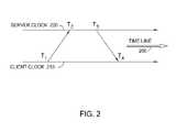
- a typical packetcontains four timestamps.
- the timestampsare designed to precisely time the transmit and receive paths of the client/server time packet interchange so that the roundtrip delay between the endpoints and the offset of the client clock may be calculated.
- the NTP serverintroduces errors into the timestamps provided to the client. Subsequently, these errors propagate to the client clock and compromise proper correction of the client clock.
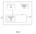
- the PTS system 300further includes a passive tap unit 316 and a latency estimator filter (LEF) 360 .
- the passive tap unit 316is a packet timestamping engine configured to monitor the network traffic flowing through the MII channel. As each packet goes by, the passive tap unit 316 analyzes the data flowing through the MII channel to determine if the incoming packet 302 is of interest to the NTP application 340 (i.e., if the incoming packet 302 is an NTP packet). If this is the case, the passive tap unit 316 is configured to trigger the hardware clock 350 to latch (i.e., temporarily record) the time-of-arrival, T rx , as shown with an arrow 319 .
- Other mediainclude communications media through which information is conveyed to a computer, such as through a computer or telephone network, including wireless communications networks.
- the latter embodimentspecifically includes transmitting information to/from the Internet and other networks.
- Such communications mediawhen carrying computer-readable instructions that direct the functions of the present invention, are embodiments of the present invention.
Landscapes
- Engineering & Computer Science (AREA)
- Computer Networks & Wireless Communication (AREA)
- Signal Processing (AREA)
- Computer Security & Cryptography (AREA)
- Synchronisation In Digital Transmission Systems (AREA)
- Data Exchanges In Wide-Area Networks (AREA)
- Computer And Data Communications (AREA)
Abstract
Description
where φ(t) is a function that describes the skew accumulation rate of the client clock and α is a measure of uncertainty of the precision NTP server time measurement.
- Step 1: μi-1=μi(bump the array down by one)
- Step 2: μi=Ttx−T3+k(update the transmission latency)
- Step 3: k=min(μi-1, μi) (calculate the new value for the correction term)
- Monitor network traffic flowing through a MIu channel, calculate transmission latency through the precision NTP server, insert a receive timestamp T2into an incoming NTP packet based on time-of-arrival latched by a hardware clock, insert a transmit timestamp T3into an outgoing NTP packet based on an estimate for the transmission latency that the outgoing NTP packet is expected to experience, and update an estimate of the transmission latency after each NTP client/server packet interchange by performing the steps of
- Detecting an incoming packet from a precision NTP client immediately after the incoming packet crosses the boundary between the external environment and the physical layer of the precision timestamping service (PTS) system;
- Triggering a time latch at the hardware clock to temporarily record time-of-arrival of the incoming packet;
- Retrieving the latched time-of-arrival from the hardware clock and inserting a receive timestamp T2equal to the latched time-of-arrival into the incoming packet;
- Requesting current time from the hardware clock and most recent estimate of the transmission latency from a latency estimator filter and inserting a transmit timestamp T3equal to the sum of the current time and the most recent estimate of the transmission latency into the outgoing packet before the outgoing packet actually crosses the boundary between the physical layer of the PTS system and the external environment;
- Detecting an outgoing packet immediately before the outgoing packet crosses the boundary between the physical layer and the external environment;
- Triggering a time latch at the hardware clock to temporarily record the time-of-departure of the outgoing packet;
- Updating the estimate of the transmission latency by calculating the offset between the software calculated transmit timestamp value and the actual measured transmit timestamp and filtering the difference to chose the minimum value of the transmission latency as the next estimate of the transmission latency;
- Provide more accurate and stable measurements of the transitions of the NTP packets both into, and out of, the precision NTP server compared to the prior art methods.
- Monitor network traffic flowing through a MIu channel, calculate transmission latency through the precision NTP server, insert a receive timestamp T2into an incoming NTP packet based on time-of-arrival latched by a hardware clock, insert a transmit timestamp T3into an outgoing NTP packet based on an estimate for the transmission latency that the outgoing NTP packet is expected to experience, and update an estimate of the transmission latency after each NTP client/server packet interchange by performing the steps of
Claims (10)
μi-1=μi;
μi=Ttx−T3+k; and
k=min(μi-1,μi).
μi-1=μi;
μi=Ttx−T3+k; and
k=min(μi-1,μi).
μi-1=μi;
μi=Ttx−T3+k; and
k=min(μi-1,μi).
Priority Applications (1)
| Application Number | Priority Date | Filing Date | Title |
|---|---|---|---|
| US11/749,666US8451867B2 (en) | 2006-05-19 | 2007-05-16 | Network time protocol precision timestamping service |
Applications Claiming Priority (2)
| Application Number | Priority Date | Filing Date | Title |
|---|---|---|---|
| US80202306P | 2006-05-19 | 2006-05-19 | |
| US11/749,666US8451867B2 (en) | 2006-05-19 | 2007-05-16 | Network time protocol precision timestamping service |
Publications (2)
| Publication Number | Publication Date |
|---|---|
| US20070268938A1 US20070268938A1 (en) | 2007-11-22 |
| US8451867B2true US8451867B2 (en) | 2013-05-28 |
Family
ID=38723995
Family Applications (1)
| Application Number | Title | Priority Date | Filing Date |
|---|---|---|---|
| US11/749,666Active2030-06-17US8451867B2 (en) | 2006-05-19 | 2007-05-16 | Network time protocol precision timestamping service |
Country Status (11)
| Country | Link |
|---|---|
| US (1) | US8451867B2 (en) |
| EP (1) | EP2025104A4 (en) |
| JP (1) | JP2009538101A (en) |
| KR (1) | KR20090024170A (en) |
| CN (1) | CN101449520B (en) |
| AU (1) | AU2007253824A1 (en) |
| BR (1) | BRPI0711770A2 (en) |
| CA (1) | CA2652594A1 (en) |
| MX (1) | MX2008014768A (en) |
| RU (1) | RU2008150317A (en) |
| WO (1) | WO2007137085A2 (en) |
Cited By (11)
| Publication number | Priority date | Publication date | Assignee | Title |
|---|---|---|---|---|
| US8767752B1 (en)* | 2010-05-03 | 2014-07-01 | Pluribus Networks, Inc. | Method and system for resource coherency and analysis in a network |
| US8891543B1 (en) | 2011-05-23 | 2014-11-18 | Pluribus Networks Inc. | Method and system for processing packets in a network device |
| US9154445B2 (en) | 2010-05-03 | 2015-10-06 | Pluribus Networks Inc. | Servers, switches, and systems with virtual interface to external network connecting hardware and integrated networking driver |
| US9160668B2 (en) | 2010-05-03 | 2015-10-13 | Pluribus Networks Inc. | Servers, switches, and systems with switching module implementing a distributed network operating system |
| US9300576B2 (en) | 2010-05-03 | 2016-03-29 | Pluribus Networks Inc. | Methods, systems, and fabrics implementing a distributed network operating system |
| US9304782B2 (en) | 2010-05-03 | 2016-04-05 | Pluribus Networks, Inc. | Network switch, systems, and servers implementing boot image delivery |
| US9306849B2 (en) | 2010-05-03 | 2016-04-05 | Pluribus Networks, Inc. | Methods and systems for managing distribute media access control address tables |
| US9319335B1 (en) | 2010-12-07 | 2016-04-19 | Pluribus Networks, Inc. | Distributed operating system for a layer 2 fabric |
| US9503347B2 (en) | 2012-12-18 | 2016-11-22 | Intel Corporation | Techniques associated with server transaction latency information |
| US9614861B2 (en) | 2015-08-26 | 2017-04-04 | Microsoft Technology Licensing, Llc | Monitoring the life cycle of a computer network connection |
| US10892972B2 (en) | 2017-04-26 | 2021-01-12 | Microsemi Storage Solutions, Inc. | Scheduled network setup test method and system |
Families Citing this family (45)
| Publication number | Priority date | Publication date | Assignee | Title |
|---|---|---|---|---|
| US9112632B2 (en)* | 2008-01-25 | 2015-08-18 | Cisco Technology, Inc. | Supporting efficient and accurate sync/followup timestamps |
| FR2928765B1 (en)* | 2008-03-13 | 2011-12-30 | Suez Environnement | SYSTEM FOR TRANSMITTING DATA FROM A MEASURING SENSOR FOR TELERELEVE WITH TIMING. |
| US8327028B1 (en)* | 2008-09-22 | 2012-12-04 | Symantec Corporation | Method and apparatus for providing time synchronization in a data protection system |
| US9727473B2 (en)* | 2008-09-30 | 2017-08-08 | Intel Corporation | Methods to communicate a timestamp to a storage system |
| US8169999B2 (en)* | 2009-01-16 | 2012-05-01 | Broadcom Corporation | Method and system for preserving content timing across femtocell interfaces via timestamp insertion |
| US8107502B2 (en)* | 2009-09-11 | 2012-01-31 | Symmetricom, Inc. | Method and apparatus for monitoring packet networks |
| US8571068B2 (en) | 2010-01-05 | 2013-10-29 | Futurewei Technologies, Inc. | Network timing distribution and synchronization using virtual network delays |
| US8644352B1 (en) | 2010-03-12 | 2014-02-04 | Marvell International Ltd. | System and method for accurate time sampling in presence of output delay |
| KR101702562B1 (en) | 2010-06-18 | 2017-02-03 | 삼성전자 주식회사 | Storage file format for multimedia streaming file, storage method and client apparatus using the same |
| US9042366B2 (en) | 2010-09-30 | 2015-05-26 | Vitesse Semiconductor Corporation | Timestamp predictor for packets over a synchronous protocol |
| CN101986590A (en)* | 2010-11-03 | 2011-03-16 | 烟台持久钟表集团有限公司 | Secondary clock synchronous time precision detection device and method |
| US8675689B2 (en)* | 2011-02-15 | 2014-03-18 | General Electric Company | Method of time synchronization of free running nodes in an avionics network |
| CN103051438A (en)* | 2011-10-11 | 2013-04-17 | 康佳集团股份有限公司 | Time synchronization method and time synchronization device |
| CN102571911B (en)* | 2011-11-17 | 2014-11-19 | 电信科学技术第五研究所 | Computer time synchronizing and monitoring method based on NTP (Network Time Protocol) protocol |
| WO2013078100A1 (en)* | 2011-11-23 | 2013-05-30 | Vitesse Semiconductor Corporation | Packet-based timing measurement |
| US9686169B2 (en)* | 2012-07-02 | 2017-06-20 | Ixia | Real-time highly accurate network latency measurement with low generated traffic or data requirements |
| WO2014094818A1 (en)* | 2012-12-17 | 2014-06-26 | Telefonaktiebolaget L M Ericsson (Publ) | Technique for monitoring data traffic |
| US9853949B1 (en) | 2013-04-19 | 2017-12-26 | Amazon Technologies, Inc. | Secure time service |
| CN104113517A (en) | 2013-04-22 | 2014-10-22 | 华为技术有限公司 | Timestamp generation method, device and system |
| WO2014184614A1 (en)* | 2013-05-13 | 2014-11-20 | Freescale Semiconductor, Inc. | Method and apparatus for enabling temporal alignment of debug information |
| US20160006526A1 (en)* | 2014-07-03 | 2016-01-07 | Qualcomm Incorporated | Systems and methods of network clock comparison |
| CN104601307B (en)* | 2015-01-15 | 2018-07-24 | 北京奥普维尔科技有限公司 | Add-on system and method based on ten thousand mbit ethernet timestamps of FPGA |
| CN104639399B (en)* | 2015-02-03 | 2018-10-09 | 新华三技术有限公司 | More primary time server detection methods and device |
| RO131470A2 (en) | 2015-04-10 | 2016-10-28 | Ixia, A California Corporation | Methods, systems and computer-readable media for one-way link delay measurement |
| US9736804B2 (en) | 2015-04-16 | 2017-08-15 | Ixia | Methods, systems, and computer readable media for synchronizing timing among network interface cards (NICS) in a network equipment test device |
| US10019333B2 (en) | 2015-04-16 | 2018-07-10 | Keysight Technologies Singapore (Holdings) Pte. Ltd. | Methods, systems, and computer readable media for emulating network devices with different clocks |
| RO131471A2 (en) | 2015-04-21 | 2016-10-28 | Ixia, A California Corporation | Methods, systems and computer-readable media for testing quality of recovered clock |
| KR101665924B1 (en) | 2015-08-04 | 2016-10-13 | 주식회사 이노와이어리스 | Frequency offset estimation system using network time protocol time offset |
| US9813226B2 (en) | 2015-08-05 | 2017-11-07 | Ixia | Modeling a clock |
| US9800595B2 (en) | 2015-09-21 | 2017-10-24 | Ixia | Methods, systems, and computer readable media for detecting physical link intrusions |
| US11799713B2 (en)* | 2015-09-22 | 2023-10-24 | Parrable Inc. | Timestamp-based association of identifiers |
| CN106230540B (en)* | 2016-06-30 | 2019-03-26 | 电信科学技术第五研究所有限公司 | High-precision NTP message method of reseptance and sending method |
| US10609054B2 (en) | 2017-04-07 | 2020-03-31 | Keysight Technologies Singapore (Sales) Pte. Ltd. | Methods, systems, and computer readable media for monitoring, adjusting, and utilizing latency associated with accessing distributed computing resources |
| US10425321B2 (en) | 2017-04-25 | 2019-09-24 | Keysight Technologies Singapore (Sales) Pte. Ltd. | Methods, systems, and computer readable media for testing time sensitive network (TSN) elements |
| US10742782B2 (en) | 2017-05-26 | 2020-08-11 | Xilinx, Inc. | Time stamping network device |
| CN113612564B (en)* | 2017-08-23 | 2024-06-14 | 华为技术有限公司 | Message processing method and network equipment |
| US10868828B2 (en)* | 2018-03-19 | 2020-12-15 | Fortinet, Inc. | Mitigation of NTP amplification and reflection based DDoS attacks |
| US11927950B2 (en)* | 2018-07-27 | 2024-03-12 | Rockwell Automation Technologies, Inc. | System and method of communicating safety data over high availability industrial control systems |
| US10965392B2 (en) | 2019-01-25 | 2021-03-30 | Keysight Technologies, Inc. | Active network tap supporting time sensitive network (TSN) standards |
| US11563768B2 (en) | 2019-01-31 | 2023-01-24 | Keysight Technologies, Inc. | Methods, systems, and computer readable media for detecting and mitigating effects of timing attacks in time sensitive networks |
| US11689440B2 (en)* | 2019-02-06 | 2023-06-27 | Marvell Israel (M.I.S.L) Ltd. | Method and apparatus for transmit time timestamping |
| EP3873009B1 (en)* | 2020-02-28 | 2024-08-21 | Siemens Aktiengesellschaft | Method for synchronising control applications over a communications network for transmitting time-critical data, network infrastructure device and communications end device |
| CN115022010B (en)* | 2022-05-30 | 2023-12-15 | 南京尤尼泰信息科技有限公司 | Intelligent anti-deception method and system for NTP client |
| WO2025185807A1 (en)* | 2024-03-05 | 2025-09-12 | Huawei Technologies Co., Ltd. | Stateless replay attack mitigation in network protocols |
| CN119154985A (en)* | 2024-11-11 | 2024-12-17 | 浙江大华技术股份有限公司 | Time synchronization method, terminal and computer readable storage medium |
Citations (12)
| Publication number | Priority date | Publication date | Assignee | Title |
|---|---|---|---|---|
| US4673979A (en)* | 1984-06-15 | 1987-06-16 | Matsushita Electric Industrial Co., Ltd. | Digital data reproducing system |
| US6535057B2 (en)* | 2000-05-29 | 2003-03-18 | Stmicroelectronics Ltd. | Programmable glitch filter |
| US20040008661A1 (en)* | 2002-03-29 | 2004-01-15 | Myles Andrew F. | Method and apparatus for clock synchronization in a wireless network |
| US20040062278A1 (en) | 2002-09-30 | 2004-04-01 | Lucent Technologies, Inc. | Systems and methods for synchronization in asynchronous transport networks |
| US20050125150A1 (en) | 2001-11-21 | 2005-06-09 | David Wang | Real time control of hardware and software via communications network |
| US20050160272A1 (en)* | 1999-10-28 | 2005-07-21 | Timecertain, Llc | System and method for providing trusted time in content of digital data files |
| US20050190797A1 (en)* | 2000-04-20 | 2005-09-01 | Mark Elliot | Network time transfer |
| US20050207387A1 (en)* | 2004-02-09 | 2005-09-22 | Semtech Corporation | Method and apparatus for aligning time references when separated by an unreliable data packet network |
| US20060056377A1 (en)* | 2004-09-16 | 2006-03-16 | Chiung-Hsien Wu | Power-saving method for a wlan station |
| US20060072694A1 (en)* | 2004-10-01 | 2006-04-06 | Hui Dai | Synchronizing clocks in wireless personal area networks |
| US20070223477A1 (en)* | 2006-03-27 | 2007-09-27 | Eidson John C | Packet recognizer with hardware/software tradeoff |
| US7603137B1 (en)* | 2005-01-27 | 2009-10-13 | Verizon Corporate Services Group Inc. & BBN Technologies Corp. | Hybrid communications link |
Family Cites Families (3)
| Publication number | Priority date | Publication date | Assignee | Title |
|---|---|---|---|---|
| WO2001088668A2 (en)* | 2000-05-18 | 2001-11-22 | Brix Networks, Inc. | Hardware time stamping and registration of packetized data method and system |
| US6868069B2 (en)* | 2001-01-16 | 2005-03-15 | Networks Associates Technology, Inc. | Method and apparatus for passively calculating latency for a network appliance |
| KR100431700B1 (en)* | 2002-08-16 | 2004-05-17 | 엘지전자 주식회사 | System And Method For Synchronizing Time Between SGSN And GGSN |
- 2007
- 2007-05-16KRKR1020087030996Apatent/KR20090024170A/ennot_activeWithdrawn
- 2007-05-16JPJP2009512223Apatent/JP2009538101A/enactivePending
- 2007-05-16BRBRPI0711770-1Apatent/BRPI0711770A2/ennot_activeIP Right Cessation
- 2007-05-16AUAU2007253824Apatent/AU2007253824A1/ennot_activeAbandoned
- 2007-05-16CNCN2007800182578Apatent/CN101449520B/ennot_activeExpired - Fee Related
- 2007-05-16WOPCT/US2007/069066patent/WO2007137085A2/enactiveApplication Filing
- 2007-05-16MXMX2008014768Apatent/MX2008014768A/ennot_activeApplication Discontinuation
- 2007-05-16RURU2008150317/09Apatent/RU2008150317A/ennot_activeApplication Discontinuation
- 2007-05-16USUS11/749,666patent/US8451867B2/enactiveActive
- 2007-05-16CACA002652594Apatent/CA2652594A1/ennot_activeAbandoned
- 2007-05-16EPEP07811895Apatent/EP2025104A4/ennot_activeWithdrawn
Patent Citations (13)
| Publication number | Priority date | Publication date | Assignee | Title |
|---|---|---|---|---|
| US4673979A (en)* | 1984-06-15 | 1987-06-16 | Matsushita Electric Industrial Co., Ltd. | Digital data reproducing system |
| US20050160272A1 (en)* | 1999-10-28 | 2005-07-21 | Timecertain, Llc | System and method for providing trusted time in content of digital data files |
| US6985499B2 (en)* | 2000-04-20 | 2006-01-10 | Symmetricom, Inc. | Precise network time transfer |
| US20050190797A1 (en)* | 2000-04-20 | 2005-09-01 | Mark Elliot | Network time transfer |
| US6535057B2 (en)* | 2000-05-29 | 2003-03-18 | Stmicroelectronics Ltd. | Programmable glitch filter |
| US20050125150A1 (en) | 2001-11-21 | 2005-06-09 | David Wang | Real time control of hardware and software via communications network |
| US20040008661A1 (en)* | 2002-03-29 | 2004-01-15 | Myles Andrew F. | Method and apparatus for clock synchronization in a wireless network |
| US20040062278A1 (en) | 2002-09-30 | 2004-04-01 | Lucent Technologies, Inc. | Systems and methods for synchronization in asynchronous transport networks |
| US20050207387A1 (en)* | 2004-02-09 | 2005-09-22 | Semtech Corporation | Method and apparatus for aligning time references when separated by an unreliable data packet network |
| US20060056377A1 (en)* | 2004-09-16 | 2006-03-16 | Chiung-Hsien Wu | Power-saving method for a wlan station |
| US20060072694A1 (en)* | 2004-10-01 | 2006-04-06 | Hui Dai | Synchronizing clocks in wireless personal area networks |
| US7603137B1 (en)* | 2005-01-27 | 2009-10-13 | Verizon Corporate Services Group Inc. & BBN Technologies Corp. | Hybrid communications link |
| US20070223477A1 (en)* | 2006-03-27 | 2007-09-27 | Eidson John C | Packet recognizer with hardware/software tradeoff |
Non-Patent Citations (5)
| Title |
|---|
| English Translation of Chinese Office Action, Chinese Patent Application No. 200780018257.8, dated Oct. 12, 2010. |
| English Translation of Second Chinese Office Action. Chinese Patent Application 200780018257.8, dated Aug. 17, 2011. |
| Johannessen, S. "Time Synchronization in a Local Area Network", Control Systems Magazine, IEEE vol. 24, Issue2, Apr. 2004 pp. 61-69. |
| Johannessen, S.; , "Time synchronization in a local area network," Control Systems, IEEE , vol. 24, No. 2, pp. 61-69, Apr. 2004.* |
| S. Johannessen, "Time synchronization in a local area network," Control Systems Magazine, IEEE, vol. 24, No. 2, pp. 61-69, 2004. [Online]. Available: http://dx.doi.org/10.1109/MCS.2004.1275432.* |
Cited By (13)
| Publication number | Priority date | Publication date | Assignee | Title |
|---|---|---|---|---|
| US9304782B2 (en) | 2010-05-03 | 2016-04-05 | Pluribus Networks, Inc. | Network switch, systems, and servers implementing boot image delivery |
| US9042233B2 (en) | 2010-05-03 | 2015-05-26 | Pluribus Networks Inc. | Method and system for resource coherency and analysis in a network |
| US9154445B2 (en) | 2010-05-03 | 2015-10-06 | Pluribus Networks Inc. | Servers, switches, and systems with virtual interface to external network connecting hardware and integrated networking driver |
| US9160668B2 (en) | 2010-05-03 | 2015-10-13 | Pluribus Networks Inc. | Servers, switches, and systems with switching module implementing a distributed network operating system |
| US9300576B2 (en) | 2010-05-03 | 2016-03-29 | Pluribus Networks Inc. | Methods, systems, and fabrics implementing a distributed network operating system |
| US8767752B1 (en)* | 2010-05-03 | 2014-07-01 | Pluribus Networks, Inc. | Method and system for resource coherency and analysis in a network |
| US9306849B2 (en) | 2010-05-03 | 2016-04-05 | Pluribus Networks, Inc. | Methods and systems for managing distribute media access control address tables |
| US9319335B1 (en) | 2010-12-07 | 2016-04-19 | Pluribus Networks, Inc. | Distributed operating system for a layer 2 fabric |
| US8891543B1 (en) | 2011-05-23 | 2014-11-18 | Pluribus Networks Inc. | Method and system for processing packets in a network device |
| US9503347B2 (en) | 2012-12-18 | 2016-11-22 | Intel Corporation | Techniques associated with server transaction latency information |
| US9614861B2 (en) | 2015-08-26 | 2017-04-04 | Microsoft Technology Licensing, Llc | Monitoring the life cycle of a computer network connection |
| US9860260B2 (en) | 2015-08-26 | 2018-01-02 | Microsoft Technology Licensing, Llc | Monitoring the life cycle of a computer network connection |
| US10892972B2 (en) | 2017-04-26 | 2021-01-12 | Microsemi Storage Solutions, Inc. | Scheduled network setup test method and system |
Also Published As
| Publication number | Publication date |
|---|---|
| CN101449520A (en) | 2009-06-03 |
| RU2008150317A (en) | 2010-06-27 |
| AU2007253824A1 (en) | 2007-11-29 |
| JP2009538101A (en) | 2009-10-29 |
| MX2008014768A (en) | 2009-04-16 |
| WO2007137085A3 (en) | 2008-01-24 |
| CN101449520B (en) | 2012-05-30 |
| EP2025104A2 (en) | 2009-02-18 |
| EP2025104A4 (en) | 2013-04-03 |
| US20070268938A1 (en) | 2007-11-22 |
| BRPI0711770A2 (en) | 2011-12-13 |
| WO2007137085A2 (en) | 2007-11-29 |
| KR20090024170A (en) | 2009-03-06 |
| CA2652594A1 (en) | 2007-11-29 |
Similar Documents
| Publication | Publication Date | Title |
|---|---|---|
| US8451867B2 (en) | Network time protocol precision timestamping service | |
| US10666371B2 (en) | System for establishing and maintaining a clock reference indicating one-way latency in a data network | |
| US10142088B2 (en) | Network clock skew estimation and calibration | |
| US11057136B1 (en) | Time correction using extension fields | |
| US8644348B2 (en) | Method for generating a robust timing correction in timing transfer systems | |
| CN102144363B (en) | A method for synchronizing clocks in a communication network | |
| US7865760B2 (en) | Use of T4 timestamps to calculate clock offset and skew | |
| US8427963B2 (en) | Method and system for analyzing and qualifying routes in packet networks | |
| CN102647270B (en) | A method for time synchronization of free-running nodes in an avionics network | |
| CN101675614A (en) | Method for synchronizing a clock of a network component with a clock of further network component and network component therefor | |
| US7643430B2 (en) | Methods and apparatus for determining reverse path delay | |
| US20180006919A1 (en) | Method, a computer program product, and a carrier for indicating one-way latency in a data network | |
| CN114586297B (en) | Synchronization method and equipment | |
| JP5479793B2 (en) | Method and apparatus for estimating one-way fluctuation delay time | |
| Stangherlin et al. | One-way delay measurement in wired and wireless mobile full-mesh networks | |
| JP3493433B2 (en) | Computer Network Time Synchronization Method | |
| KR20120031511A (en) | Method for synchronizing a client clock frequency with a server clock frequency | |
| WO2020132834A1 (en) | Method and device for stamping processing |
Legal Events
| Date | Code | Title | Description |
|---|---|---|---|
| AS | Assignment | Owner name:SYMMETRICOM, INC., CALIFORNIA Free format text:ASSIGNMENT OF ASSIGNORS INTEREST;ASSIGNOR:DOWD, GREGORY LOUIS;REEL/FRAME:020424/0476 Effective date:20070510 | |
| STCF | Information on status: patent grant | Free format text:PATENTED CASE | |
| AS | Assignment | Owner name:MICROSEMI FREQUENCY AND TIME CORPORATION, CALIFORN Free format text:CHANGE OF NAME;ASSIGNOR:SYMMETRICOM, INC.;REEL/FRAME:032264/0195 Effective date:20131203 | |
| AS | Assignment | Owner name:BANK OF AMERICA, N.A., AS COLLATERAL AGENT, NORTH Free format text:SECURITY AGREEMENT;ASSIGNORS:MICROSEMI CORPORATION;MICROSEMI CORP.-ANALOG MIXED SIGNAL GROUP;MICROSEMI SEMICONDUCTOR (U.S.) INC.;AND OTHERS;REEL/FRAME:035477/0057 Effective date:20150421 | |
| AS | Assignment | Owner name:MICROSEMI SEMICONDUCTOR (U.S.) INC., A DELAWARE CO Free format text:RELEASE BY SECURED PARTY;ASSIGNOR:BANK OF AMERICA, N.A.;REEL/FRAME:037558/0711 Effective date:20160115 Owner name:MICROSEMI CORP.-MEMORY AND STORAGE SOLUTIONS (F/K/ Free format text:RELEASE BY SECURED PARTY;ASSIGNOR:BANK OF AMERICA, N.A.;REEL/FRAME:037558/0711 Effective date:20160115 Owner name:MICROSEMI COMMUNICATIONS, INC. (F/K/A VITESSE SEMI Free format text:RELEASE BY SECURED PARTY;ASSIGNOR:BANK OF AMERICA, N.A.;REEL/FRAME:037558/0711 Effective date:20160115 Owner name:MICROSEMI SOC CORP., A CALIFORNIA CORPORATION, CAL Free format text:RELEASE BY SECURED PARTY;ASSIGNOR:BANK OF AMERICA, N.A.;REEL/FRAME:037558/0711 Effective date:20160115 Owner name:MICROSEMI FREQUENCY AND TIME CORPORATION, A DELAWA Free format text:RELEASE BY SECURED PARTY;ASSIGNOR:BANK OF AMERICA, N.A.;REEL/FRAME:037558/0711 Effective date:20160115 Owner name:MICROSEMI CORP.-ANALOG MIXED SIGNAL GROUP, A DELAW Free format text:RELEASE BY SECURED PARTY;ASSIGNOR:BANK OF AMERICA, N.A.;REEL/FRAME:037558/0711 Effective date:20160115 Owner name:MICROSEMI CORPORATION, CALIFORNIA Free format text:RELEASE BY SECURED PARTY;ASSIGNOR:BANK OF AMERICA, N.A.;REEL/FRAME:037558/0711 Effective date:20160115 | |
| AS | Assignment | Owner name:MORGAN STANLEY SENIOR FUNDING, INC., NEW YORK Free format text:PATENT SECURITY AGREEMENT;ASSIGNORS:MICROSEMI CORPORATION;MICROSEMI SEMICONDUCTOR (U.S.) INC. (F/K/A LEGERITY, INC., ZARLINK SEMICONDUCTOR (V.N.) INC., CENTELLAX, INC., AND ZARLINK SEMICONDUCTOR (U.S.) INC.);MICROSEMI FREQUENCY AND TIME CORPORATION (F/K/A SYMMETRICON, INC.);AND OTHERS;REEL/FRAME:037691/0697 Effective date:20160115 | |
| FPAY | Fee payment | Year of fee payment:4 | |
| AS | Assignment | Owner name:IP GEM GROUP, LLC, CALIFORNIA Free format text:ASSIGNMENT OF ASSIGNORS INTEREST;ASSIGNOR:MICROSEMI FREQUENCY AND TIME CORPORATION;REEL/FRAME:043137/0834 Effective date:20170721 | |
| AS | Assignment | Owner name:MICROSEMI CORP. - RF INTEGRATED SOLUTIONS, CALIFOR Free format text:RELEASE BY SECURED PARTY;ASSIGNOR:MORGAN STANLEY SENIOR FUNDING, INC.;REEL/FRAME:046251/0391 Effective date:20180529 Owner name:MICROSEMI CORP. - POWER PRODUCTS GROUP, CALIFORNIA Free format text:RELEASE BY SECURED PARTY;ASSIGNOR:MORGAN STANLEY SENIOR FUNDING, INC.;REEL/FRAME:046251/0391 Effective date:20180529 Owner name:MICROSEMI CORPORATION, CALIFORNIA Free format text:RELEASE BY SECURED PARTY;ASSIGNOR:MORGAN STANLEY SENIOR FUNDING, INC.;REEL/FRAME:046251/0391 Effective date:20180529 Owner name:MICROSEMI SOC CORP., CALIFORNIA Free format text:RELEASE BY SECURED PARTY;ASSIGNOR:MORGAN STANLEY SENIOR FUNDING, INC.;REEL/FRAME:046251/0391 Effective date:20180529 Owner name:MICROSEMI SEMICONDUCTOR (U.S.), INC., CALIFORNIA Free format text:RELEASE BY SECURED PARTY;ASSIGNOR:MORGAN STANLEY SENIOR FUNDING, INC.;REEL/FRAME:046251/0391 Effective date:20180529 Owner name:MICROSEMI COMMUNICATIONS, INC., CALIFORNIA Free format text:RELEASE BY SECURED PARTY;ASSIGNOR:MORGAN STANLEY SENIOR FUNDING, INC.;REEL/FRAME:046251/0391 Effective date:20180529 Owner name:MICROSEMI FREQUENCY AND TIME CORPORATION, CALIFORN Free format text:RELEASE BY SECURED PARTY;ASSIGNOR:MORGAN STANLEY SENIOR FUNDING, INC.;REEL/FRAME:046251/0391 Effective date:20180529 | |
| MAFP | Maintenance fee payment | Free format text:PAYMENT OF MAINTENANCE FEE, 8TH YEAR, LARGE ENTITY (ORIGINAL EVENT CODE: M1552); ENTITY STATUS OF PATENT OWNER: LARGE ENTITY Year of fee payment:8 | |
| MAFP | Maintenance fee payment | Free format text:PAYMENT OF MAINTENANCE FEE, 12TH YEAR, LARGE ENTITY (ORIGINAL EVENT CODE: M1553); ENTITY STATUS OF PATENT OWNER: LARGE ENTITY Year of fee payment:12 |