US8451731B1 - Network monitoring using virtual packets - Google Patents
Network monitoring using virtual packetsDownload PDFInfo
- Publication number
- US8451731B1 US8451731B1US12/180,193US18019308AUS8451731B1US 8451731 B1US8451731 B1US 8451731B1US 18019308 AUS18019308 AUS 18019308AUS 8451731 B1US8451731 B1US 8451731B1
- Authority
- US
- United States
- Prior art keywords
- virtual
- packets
- flow
- information
- virtual packets
- Prior art date
- Legal status (The legal status is an assumption and is not a legal conclusion. Google has not performed a legal analysis and makes no representation as to the accuracy of the status listed.)
- Active
Links
- 238000012544monitoring processMethods0.000titleclaimsdescription26
- 208000024891symptomDiseases0.000claimsabstractdescription54
- 238000005070samplingMethods0.000claimsabstractdescription41
- 238000012806monitoring deviceMethods0.000claimsabstractdescription27
- 238000000034methodMethods0.000claimsdescription59
- 238000001514detection methodMethods0.000claimsdescription27
- 230000004044responseEffects0.000claimsdescription9
- 238000004891communicationMethods0.000abstractdescription27
- 230000000694effectsEffects0.000abstractdescription25
- 238000005111flow chemistry techniqueMethods0.000abstractdescription2
- 230000008569processEffects0.000description23
- 230000005856abnormalityEffects0.000description14
- 230000006399behaviorEffects0.000description13
- 238000004364calculation methodMethods0.000description9
- 238000009499grossingMethods0.000description9
- 238000012545processingMethods0.000description9
- 238000009826distributionMethods0.000description7
- 238000012549trainingMethods0.000description7
- 230000007246mechanismEffects0.000description6
- 230000003442weekly effectEffects0.000description6
- 230000007774longtermEffects0.000description5
- 238000010586diagramMethods0.000description4
- 230000003993interactionEffects0.000description4
- 230000002452interceptive effectEffects0.000description3
- 230000000750progressive effectEffects0.000description3
- 238000010183spectrum analysisMethods0.000description3
- 238000012360testing methodMethods0.000description3
- 230000002159abnormal effectEffects0.000description2
- 238000004458analytical methodMethods0.000description2
- 238000003491arrayMethods0.000description2
- 230000015556catabolic processEffects0.000description2
- 238000006731degradation reactionMethods0.000description2
- 230000000737periodic effectEffects0.000description2
- 238000009827uniform distributionMethods0.000description2
- 206010024264LethargyDiseases0.000description1
- 230000002411adverseEffects0.000description1
- 238000013142basic testingMethods0.000description1
- 230000008859changeEffects0.000description1
- 238000012512characterization methodMethods0.000description1
- 230000008867communication pathwayEffects0.000description1
- 230000000593degrading effectEffects0.000description1
- 230000001419dependent effectEffects0.000description1
- 239000006185dispersionSubstances0.000description1
- 239000000284extractSubstances0.000description1
- 230000000670limiting effectEffects0.000description1
- 230000007257malfunctionEffects0.000description1
- 230000008520organizationEffects0.000description1
- 238000005192partitionMethods0.000description1
- 238000013138pruningMethods0.000description1
- 230000008439repair processEffects0.000description1
- 230000002441reversible effectEffects0.000description1
- 230000003068static effectEffects0.000description1
Images


Classifications
- H—ELECTRICITY
- H04—ELECTRIC COMMUNICATION TECHNIQUE
- H04L—TRANSMISSION OF DIGITAL INFORMATION, e.g. TELEGRAPHIC COMMUNICATION
- H04L41/00—Arrangements for maintenance, administration or management of data switching networks, e.g. of packet switching networks
- H04L41/06—Management of faults, events, alarms or notifications
- H04L41/0631—Management of faults, events, alarms or notifications using root cause analysis; using analysis of correlation between notifications, alarms or events based on decision criteria, e.g. hierarchy, tree or time analysis
- H04L41/0645—Management of faults, events, alarms or notifications using root cause analysis; using analysis of correlation between notifications, alarms or events based on decision criteria, e.g. hierarchy, tree or time analysis by additionally acting on or stimulating the network after receiving notifications
- H—ELECTRICITY
- H04—ELECTRIC COMMUNICATION TECHNIQUE
- H04L—TRANSMISSION OF DIGITAL INFORMATION, e.g. TELEGRAPHIC COMMUNICATION
- H04L43/00—Arrangements for monitoring or testing data switching networks
- H04L43/02—Capturing of monitoring data
- H04L43/026—Capturing of monitoring data using flow identification
- H—ELECTRICITY
- H04—ELECTRIC COMMUNICATION TECHNIQUE
- H04L—TRANSMISSION OF DIGITAL INFORMATION, e.g. TELEGRAPHIC COMMUNICATION
- H04L43/00—Arrangements for monitoring or testing data switching networks
- H—ELECTRICITY
- H04—ELECTRIC COMMUNICATION TECHNIQUE
- H04L—TRANSMISSION OF DIGITAL INFORMATION, e.g. TELEGRAPHIC COMMUNICATION
- H04L43/00—Arrangements for monitoring or testing data switching networks
- H04L43/04—Processing captured monitoring data, e.g. for logfile generation
- H—ELECTRICITY
- H04—ELECTRIC COMMUNICATION TECHNIQUE
- H04L—TRANSMISSION OF DIGITAL INFORMATION, e.g. TELEGRAPHIC COMMUNICATION
- H04L43/00—Arrangements for monitoring or testing data switching networks
- H04L43/08—Monitoring or testing based on specific metrics, e.g. QoS, energy consumption or environmental parameters
- H04L43/0805—Monitoring or testing based on specific metrics, e.g. QoS, energy consumption or environmental parameters by checking availability
- H04L43/0817—Monitoring or testing based on specific metrics, e.g. QoS, energy consumption or environmental parameters by checking availability by checking functioning
- H—ELECTRICITY
- H04—ELECTRIC COMMUNICATION TECHNIQUE
- H04L—TRANSMISSION OF DIGITAL INFORMATION, e.g. TELEGRAPHIC COMMUNICATION
- H04L43/00—Arrangements for monitoring or testing data switching networks
- H04L43/02—Capturing of monitoring data
- H04L43/022—Capturing of monitoring data by sampling
- H—ELECTRICITY
- H04—ELECTRIC COMMUNICATION TECHNIQUE
- H04L—TRANSMISSION OF DIGITAL INFORMATION, e.g. TELEGRAPHIC COMMUNICATION
- H04L43/00—Arrangements for monitoring or testing data switching networks
- H04L43/20—Arrangements for monitoring or testing data switching networks the monitoring system or the monitored elements being virtualised, abstracted or software-defined entities, e.g. SDN or NFV
- Y—GENERAL TAGGING OF NEW TECHNOLOGICAL DEVELOPMENTS; GENERAL TAGGING OF CROSS-SECTIONAL TECHNOLOGIES SPANNING OVER SEVERAL SECTIONS OF THE IPC; TECHNICAL SUBJECTS COVERED BY FORMER USPC CROSS-REFERENCE ART COLLECTIONS [XRACs] AND DIGESTS
- Y02—TECHNOLOGIES OR APPLICATIONS FOR MITIGATION OR ADAPTATION AGAINST CLIMATE CHANGE
- Y02D—CLIMATE CHANGE MITIGATION TECHNOLOGIES IN INFORMATION AND COMMUNICATION TECHNOLOGIES [ICT], I.E. INFORMATION AND COMMUNICATION TECHNOLOGIES AIMING AT THE REDUCTION OF THEIR OWN ENERGY USE
- Y02D30/00—Reducing energy consumption in communication networks
- Y02D30/50—Reducing energy consumption in communication networks in wire-line communication networks, e.g. low power modes or reduced link rate
Definitions
- MTTRmean time to repair
- One known problemis when monitoring network traffic for a relatively large network, the amount of information relating to that network traffic can also be relatively large.
- the sheer volume of nodes and traffic in the networkmakes it more difficult for a network monitoring device to keep up with that relatively large amount of information.
- a network monitoring deviceincludes a flow processing element, disposed to receive flow information relating to network flows, and to generate a set of virtual packets, each representing a portion of a network flow.
- the virtual packetspreferably are maintained in a time-sequential order, and read by elements of the network monitoring device to generate information relating to network traffic, such as symptoms affecting the communication network, problems affecting the communication network, and otherwise.
- the network monitoring devicerandomly samples virtual packets, with at least one of two effects: (1) flow information from traffic reporting devices that are themselves sampling a differing rates can be equalized, with the effect of standardizing information from all of them; (2) the network monitoring device itself can restrict its attention to a fraction of all virtual packets, with the effect of keeping up with a relatively large number of virtual packets.
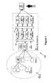
- FIG. 1shows a block diagram of a system.
- FIG. 2shows a functional block diagram of a distributed system.
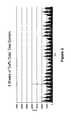
- FIG. 3shows accumulated traffic data
- FIG. 4shows a frequency table
- FIG. 1A first figure.
- FIG. 1shows a block diagram of a system.
- One embodiment of a system 100includes elements as shown in the FIG. 1 , including at least: a communication network 110 , a set of endpoints 120 included in or coupled to that communication network, a set of traffic reporting devices 130 included in or coupled to that communication network, at least one network monitoring device 140 coupled to that communication network, and (optionally) a user station 150 operated by a user 160 .
- the communication network 110might include any form of communication pathway, such as for example, a broadcast or narrowcast network, a bus or crossbar switch or other substantially internal communications path in a computing device, a LAN or WAN, a set of external devices disposed for cluster computing or other distributed computing, an enterprise network or internet or intranet, or otherwise.
- a broadcast or narrowcast networksuch as for example, a broadcast or narrowcast network, a bus or crossbar switch or other substantially internal communications path in a computing device, a LAN or WAN, a set of external devices disposed for cluster computing or other distributed computing, an enterprise network or internet or intranet, or otherwise.
- the endpoints 120might include any form of processing or storage device capable of sending or receiving information using that communication network 110 .
- the endpoints 120include at least the capability for sending or receiving messages, also sometimes called “packets”, using that communication network 110 .
- each packetincludes at least a source address, a source port identifier, a destination address, a destination port identifier, and payload information.
- the traffic reporting devices 130might include any form of device capable of identifying network traffic and generating information regarding that network traffic.
- the traffic reporting devices 130include routing devices, also capable of sending and receiving messages to and from the endpoints 120 and other routing devices, which collect flow information regarding network “flows” and report that flow information according to known flow information reporting protocols.
- the network monitoring device 140preferably include elements as shown in the FIG. 1 , including at least: a flow processor 210 , a virtual packet buffer 220 , a discovery engine 231 , a monitoring engine 232 , a profiling engine 233 , a detection engine 234 , a virtual bus 240 , a UI server 251 , a database server 252 , a correlation engine 253 , and a notification server 254 .
- the user station 150might include any form of device capable of communicating with the UI server (as described below) and under control of one or more users 160 .
- the flow processor 210includes any form of processing element capable of receiving flow information. Upon receiving a message including flow information, the flow processor 210 parses that flow information, determines a start time and an end time for that flow information, and determines a number of packets reported by the traffic reporting device 130 that provided that flow information. The flow processor 210 preferably generates a sequence of virtual packets, each representing one or more real packets, but differing from real packets in that (1) virtual packets do not include any payload information, and (2) virtual packets can be generated to be equally distributed over the time reported for the flow information, rather than the possible unequal distribution that real packets might have manifested.
- the flow processor 210preferably includes a virtual packet reordering buffer 211 , in which it preferably assures that virtual packets are properly ordered with respect to their (generated) arrival time. As the flow processor 210 receives flow information, the flow processor 210 continues to generate new virtual packets and to place those new virtual packets in the reordering buffer so that all virtual packets remain in time order within the reordering buffer. Virtual packets older than a selected time duration (in a preferred embodiment, 60 seconds) preferably are forwarded from the reordering buffer to the virtual packet buffer 220 .
- a selected time durationin a preferred embodiment, 60 seconds
- the virtual packet buffer 220preferably includes a sequence of virtual packets, ordered with respect to their time of arrival, generated by the flow processor 210 and written by the flow processor 210 into the virtual packet buffer 220 .
- a write pointer 221can be maintained to show where the flow processor 210 is presently writing to the virtual packet buffer 220 .
- Those other elements of the network monitoring device 140 that can be coupled to the virtual packet buffer 220including the discovery engine 231 , the monitoring engine 232 , the profiling engine 233 , and the detection engine 234 , preferably read from the virtual packet buffer 220 , each maintaining its own read pointer to where they are presently reading from the virtual packet buffer 220 . If any of the elements of the network monitoring device 140 that are coupled to the virtual packet buffer 220 catch up with the write pointer 221 , they wait until the flow processor 210 has written new information into the virtual packet buffer 220 and updated the write pointer 221 .
- the discovery engine 231preferably reads virtual packets from the virtual packet buffer 220 , and generates discovery information relating to identification of endpoints 120 and of the applications they use.
- the monitoring engine 232preferably receives discovery information from the discovery engine 231 , reads virtual packets from the virtual packet buffer 220 , and generates monitoring information relating to activity of endpoints 120 and applications in the communication network 110 .
- the profiling engine 233preferably receives monitoring information from the monitoring engine 232 , reads virtual packets from the virtual packet buffer 220 , and generates profiling information relating to activity of endpoints 120 and applications in the communication network 110 .
- each network monitoring device 140maintains locally the profiling information and historical traffic data for all of the endpoints associated with its address blocks. Profiling, monitoring, and detection are done locally at the network monitoring device 140 .
- Historical profiling informationallows for profiling to be performed retrospectively, such that reconstructions of prior network performance may be employed.
- the detection engine 234preferably receives profiling information from the profiling engine 233 , and generates symptom information relating to activity of endpoints 120 and applications in the communication network 110 .
- the virtual bus 240preferably provides for communication among elements of the network monitoring device 140 , including the discovery engine 231 , the monitoring engine 232 , the profiling engine 233 , the detection engine 234 , the UI server 251 , the database 252 , the correlation engine 253 and the notification server 254 .
- the virtual bus 240includes a set of subscription channels, each including information posted to those subscription channels by one or more elements of the network monitoring device 140 coupled to the virtual bus 240 , and each readable by one or more elements of the symptom identification device 140 coupled to the virtual bus 240 .
- the virtual bus 240includes a process disposed to receive messages from each of those elements of the network monitoring device 140 . Those messages might indicate either information to post to a selected subscription channel, or a request to receive information from a selected subscription channel. In the former case, the virtual bus 240 process records that information in association with the selected subscription channel. In the latter case, the virtual bus 240 process, from time to time, retrieves information associated with the selected subscription channel and sends that information to the requesting element, until such time as that requesting element asks the virtual bus 240 process to remove it from the selected subscription channel.
- the UI server 251preferably receives information from the virtual bus 240 , subscribing to that information it needs from the correlation engine 253 (as described below).
- the UI server 251generates a set of information for presentation to users 160 using their user stations 150 as clients in a client-server interactive system.
- the UI server 251operates as the server portion of a client-server interactive system, receiving requests from, and making responses to, the user stations 150 operating as clients, with the effect that users 160 might use their user stations 150 to receive status information and present commands to the UI server 251 .
- the database server 253preferably maintains a database of information for use by elements of the network monitoring device 140 .
- the correlation engine 253preferably receives symptom information from the detection engine 234 , generates information relating to problems affecting the communication network 110 , in response to that symptom information, and provides that problem information to the UI server 251 and to the notification server 254 , with the effect that it can be communicated to users 160 .
- the notification server 254preferably receives information from the correlation engine 253 relating to problems affecting the communication network 110 , and forwards that information to any user stations 150 requesting notification.
- User stations 160might request notification by sending messages to the network monitoring device 140 with attention to its notification server 254 .
- the notification server 254might send notification to those user stations 150 using email, instant messaging (IM), short message service (SMS), or any other form of notification.
- IMinstant messaging
- SMSshort message service
- User stations 150preferably are directed by users 160 to interact with the UI server 251 as the client portion of a client-server interactive system, making requests to, and receiving responses from, the UI server 251 , with the effect that users 160 might use their user stations 150 to receive status information and present commands to the UI server 251 .
- the flow processor 210In the event the flow processor 210 cannot keep up with the amount of incoming flow information, or in the event the virtual packet buffer 220 becomes full from virtual packets (i.e., the discovery engine 231 , monitoring engine 232 , profiling engine 233 , and detection engine 234 cannot read those virtual packets as fast as the flow processor 210 writes them), the flow processor 210 should limit the number of virtual packets it generates and places in the virtual packet buffer 220 .
- the flow processor 210records, in the virtual packet buffer 220 , only one virtual packet for each 1/ ⁇ of the virtual packets it generates. Thus, if ⁇ 1/10, the flow processor 210 records only one virtual packet for each ten of the virtual packets it generates.
- the sampling parameter ⁇is preferably selected by a user 160 , but might instead be selected dynamically by an element of the network monitoring device 140 , such as the flow processor 210 itself.
- the flow processor 210upon generating each virtual packet, preferably generates a random number ⁇ in the range [0, 1], i.e., 0 ⁇ 1, and records that virtual packet in the virtual packet buffer 220 if and only if ⁇ , i.e., each generated virtual packet preferably is recorded in the virtual packet buffer 220 with probability ⁇ . This has the effect that if ⁇ 1, every generated virtual packet is recorded in the virtual packet buffer 220 , while if ⁇ 1/n, only one out of every n virtual packets are recorded in the virtual packet buffer 220 .
- the network monitoring device 140When operating with a sampling parameter ⁇ 1, the network monitoring device 140 causes its elements, including the discovery engine 231 , the monitoring engine 232 , the profiling engine 233 , and the detection engine 234 , to adjust their operation accordingly.
- the monitoring engine 232should report 1/ ⁇ as much network traffic (in bits/second and packets/second) as it actually sees, while the profiling engine 233 and the detection engine 234 should adjust their operation to note that the mean and standard deviation of observed network traffic data (including observed bits/second and observed packets/second) are other than their raw observed values. This has the effect that some parameters, such as the mean value, should be adjusted linearly, while other parameters, such as the standard deviation, should be adjusted other than linearly.
- the flow processor 210receives flow information from more than one traffic reporting device 130 , but those distinct traffic reporting devices 130 are themselves using different sampling rates to generate their flow information, the flow processor 210 preferably uses sampling on flow information from some of those traffic reporting devices 130 , with the effect of equalizing the reported information across all traffic reporting devices 130 it is listening to.
- the flow processor 210will use sampling to adjust the flow information it receives from the first traffic reporting device 130 so that it can treat both traffic reporting devices 130 as if they were sampling at the same rate of 1:10.
- FIG. 2shows a block diagram of a distributed system 200 .
- FIG. 2One embodiment of a distributed system 200 as shown in FIG. 2 includes a problem identification device (PI) 260 and one or more symptom identification devices (SI) 262 .
- the distributed system 200preferably includes all the components of the system of FIG. 1 , but in the distributed system 200 , the elements can be located throughout a communication network to provide for local servicing of network monitoring.
- the flow processors 210 of a plurality of SI devices 262are coupled to a communication network 110 and to a PI device 260 .
- the flow processor 210 , buffer 211 , pointer 221operate to form data for the virtual address buffer 220 as described above.
- the virtual bus 240provides for communication among elements of the PI device 262 , including the discovery engine 231 , the monitoring engine 232 , the profiling engine 233 , the detection engine 234 and a database 252 .
- the virtual bus 240is also preferably coupled to a network, which may be the communication network 110 .
- the virtual bus 240provides at least symptom data and UI data from a first portion of a virtual bus located in SI device 262 to a second portion of a the virtual bus 240 located in a PI device 260 .
- the problem identification device 260includes at least a UI server 251 , a database 252 , a correlation engine 253 and a notification server 254 as described above. Additionally, the PI device 260 provides for operation of a user station 150 through the UI engine 251 and notification server 254 as described above.
- each symptom identification device 262preferably is associated with a subset of flow generating routers through the network 110 .
- associated with these routersis a local subset of endpoints whose originating traffic is first handled by these routers.
- Each symptom identification device 262can be assigned a subset of the universe of network cross-points each of whose endpoint component belongs to the local subset of endpoints.
- a crosspointpreferably is an instance of a cross-product of device identification and one or more of application, location or time dimensions.
- Each symptom identification device 262preferably is assigned a subset of locations that are associated with the local set of endpoints and an equal but arbitrary subset of applications and time intervals.
- the SI device 262receives data flows from associated routers for which the source address of the data flows match the endpoint components of the cross-points that the SI device 262 monitors. This allows the SI device 262 to process all relevant traffic for the crosspoints associated with the SI device 262 .
- the SI device 262incorporates a map of the associated crosspoints.
- the flow processor 210 of the SI device 262receives a flow record in which the destination endpoint is not local (not one of the endpoints associated with the symptom identification device 262 ), it preferably processes the flow record locally instead of sending it for processing to the flow record's endpoint.
- the SI device 262then relays the flow record to a second symptom identification device 262 associated with the destination endpoint of the flow.
- the second symptom identification device 262would be the device responsible for the processing at destination endpoint.
- the relayed flow recordcontains an indicator to prevent double counting by the second symptom identification device 262 .
- the receiving symptom identification device's 262 flow-processor 210gets the relayed flow record, it processes the flow record for use in the second symptom identification device 262 . In this way both the incoming and outgoing traffic of the subset of endpoints can be monitored.
- aggregate flow recordsmay be relayed to various devices through the communication network 110 .
- a flow-relay processcan be used to partition the flow packets for distribution and reconstitute them for the receiving symptom identification device 262 .
- Each symptom identification device 262maintains the profiling information and historical traffic flow data for all of the local subset of endpoints associated with the symptom identification device 262 .
- Profiling, monitoring, and detectionpreferably are done locally at each symptom identification device 262 .
- the SI device 262sends the symptom events and UI data to the problem identification device 260 .
- the problem identification devicecan be encoded to analyze the symptoms and correlate them into problems. This allows for scalability such that a single problem identification device 260 can support multiple symptom identification devices 262 .
- the PI device 260 and the SI devise 262communicate through the virtual bus 240 .
- the virtual bus 240includes a process disposed to receive messages from each of those elements of the network monitoring device 140 . Those messages might indicate either information to post to a selected subscription channel, or a request to receive information from a selected subscription channel. In the former case, the virtual bus 240 process records that information in association with the selected subscription channel. In the latter case, the virtual bus 240 process, from time to time, retrieves information associated with the selected subscription channel and sends that information to the requesting element, until such time as that requesting element asks the virtual bus 240 process to remove it from the selected subscription channel.
- UI information and symptom informationcan be sent between the PI device 260 and the SI device 262 through the virtual bus 240 . Alternatively the UI information and/or symptom information may be communicated through the network 110 .
- the flow processor 210receives flow information from more than one traffic reporting device or router, but those distinct devices may themselves use different sampling rates to generate their flow information.
- the flow processor 210uses sampling on flow information from some of those devices, with the effect of equalizing the reported information across all devices it is listening to.
- the flow processor 210will use sampling to adjust the flow information it receives from the first traffic reporting device 130 so that it can treat both traffic reporting devices 130 as if they were sampling at the same rate of 1:10.
- a problem identification device 260When operating with differing sampling rates, a problem identification device 260 causes its elements to adjust their operation accordingly.
- the monitoring engine 232should report 1/ ⁇ as much network traffic (in bits/second and packets/second) as it actually sees, while the profiling engine 233 and the detection engine 234 should adjust their operation to note that the mean and standard deviation of observed network traffic data (including observed bits/second and observed packets/second) are other than their raw observed values. This has the effect that some parameters, such as the mean value, should be adjusted linearly, while other parameters, such as the standard deviation, should be adjusted other than linearly.
- the sampling parameter ⁇is preferably selected by a user 160 , but might instead be selected dynamically by an element of the distributed network such as the problem identification device 260 or the symptom identification device 262 . This allows for greater control over network monitoring for larger networks.
- crosspointgenerally describes an entity which can be determined by training, creating a baseline, and eventually detecting symptoms.
- IDsnamesd network endpoints
- ApplicationsLocations, Interfaces, and Time Periods. Both incoming and outgoing activity for each of these crosspoints may be profiled.
- ID and Application crosspointsmay be automatically generated using a discovery process, followed by an object creation process.
- the discovery processlooks at flows representing packets on the network. From each flow, it extracts information corresponding to some of the original packet header information for each packet (src/dst IP address, port, and protocol), and creates a virtual packet with that information.
- the discovery processpreferably keeps an exponential moving average (EMA) of the bit rate and packet rate for each IP address that it sees. If or when the EMA exceeds a certain user-defined threshold, then this IP address becomes a candidate for ID creation. If possible, a reverse DNS lookup may be used to determine the name. If successful, a name may be generated from its LDAP Owner field of the ManagedBy attribute and use the owner name instead of the DNS name. If unsuccessful, the name may be derived from its MAC address obtained via an SNMP query of the endpoint. Alternatively, the system user may declare that this area of the network is “static,” in which case a name may be created using the IP address and a user-supplied suffix.
- EMAexponential moving average
- the potential ID-base crosspointspreferably are written to a text file. Another process can periodically check this file and creates the ID crosspoints from it. This creation may be throttled to help prevent the system from being overwhelmed with simultaneous creation of large numbers of IDs.
- the discovery processpreferably checks the port of each virtual packet. If the port is a well-known port for a known application, or if it is a port that already has been assigned for a particular application, then traffic for that port can be accounted for in the bit rate and packet rate of the application. However, if the port is not already mapped to an application, then the discovery process can keep an EMA of the bit rate and packet rate for that port. If or when the EMA exceeds the user-defined threshold, then the port can be a candidate to become an application.
- These ports that are potential applicationscan be written to a text file. Another process can periodically check this text file and displays these ports to the user. Users can either specify for these ports to become new application(s), or they can specify for them to join existing application(s), for example.
- the location-based crosspointscan be specified by the system user in terms of subnet addresses to be included and/or ignored.
- the Interface-based cross-pointscan be discovered interfaces associated with flow data.
- the time period-based crosspointscan be pre-specified as particular hours of a workday or non-workday.
- EMAexponential moving average
- Two metrics that may be stored for each profile pointare the minimum and maximum for four different values: packet rate, bit rate, interaction rate, and burstiness.
- the packet rate and bit rate valuescan be the EMA values updated periodically, such as once per second for example, using the average packet rate and average bit rate for that second.
- Interaction rateis a measure of how many IP addresses are actively:
- Burstinessis the rate of change of bit rate.
- the literaturediscusses several commonly used measures of traffic burstiness:
- Using the peak-to-mean ratiocan be an efficient metric to calculate realtime. It may be computed by taking the ratio of the peak of a very short-term rate to a long-term average rate; comparing, for example, the peak of a 1-second EMA (over a 5-minute interval) with a 5-minute EMA.
- the minimum and maximum EMA values for these various metricsallow symptoms (or abnormalities) to be flagged that are higher than normal (hyper) or lower than normal (hypo).
- each crosspointhas affinity profiling metrics.
- Affinityrepresents the strength of correspondence between the crosspoint and another specific entity (called an “affinity point”).
- the affinity metriccan be bit rate, bit rate*pkt rate (in order to allow both factors to positively influence the metric), or something else.
- the detection mechanismcan be determined by testing each crosspoint once per second using both the basic tests and the complex tests. If one of the tests signals an abnormality (i.e., the current EMA is significantly less than the minimum threshold, significantly more than the maximum threshold, or significantly different than the histogram), then a flag can be set for that profile point. If the crosspoint continues to experience the abnormality for a specified period, then it can be declared a “symptom event” and interested processes can be notified.
- an abnormalityi.e., the current EMA is significantly less than the minimum threshold, significantly more than the maximum threshold, or significantly different than the histogram
- the detection mechanismattempts to determine further information about the excessive activity: where it's primarily coming from (for an incoming abnormality) or going to (for an outgoing abnormality), which protocol was primarily involved, and which port was primarily involved. We obtain this information by monitoring the IP addresses, ports, and protocols for all packets corresponding to a profile point involved in a hyper abnormality.
- the predominant IP addresscan be determined by updating an EMA value for each matching IP address in an IP address tree as packets arrive. Tree nodes corresponding to IP addresses that don't receive packets will be aged, and eventually pruned from the tree if their EMA value gets small enough. Nodes with significant EMA values will stay on the tree. Periodically the EMA values from the tree get sorted, and the top IP address can be determined. If the top address has a significantly higher EMA than the other addresses, then it can be considered a predominant address and can be reported in the notification.
- the port and protocolcan be found in a similar manner, but use arrays rather than trees.
- the EMA values corresponding to different ports and protocolsget continually updated as packets arrive; they also periodically get aged, and possibly can be purged if their EMA value is small enough. Periodically the arrays can be sorted, and the top port and protocol emerge. If they have a significantly higher EMA than the others, then they will be reported in the notification.
- the symptom eventwill continue until the profile point experiences a specified period without any abnormalities. Once this occurs, the symptom event can be deemed over.
- the profiling and detection mechanismscan operate in parallel. Periodically the profiling calculations can be updated as well as the detection calculations. If the detection mechanism indicates that an abnormality is present, then profiling can be temporarily stopped to avoid profiling on “bad” traffic patterns. As soon as the abnormality has ended, profiling resumes, beginning with the last saved good profile.
- the traffic levelsmay be a specified amount higher (than max), lower (than min), or different (than histograms). If the traffic levels are only slightly outside the previously observed ranges and not exceeding the specified amount, profiling continues without declaring an abnormality. This permits the profiles to adapt to naturally changing traffic environments. However, as soon as the differences are greater than the specified limit, profiling can be stopped and an abnormality can be declared.
- the profile mechanismAfter a specified amount of time has elapsed where the training profile for a crosspoint (known as the “emerging profile”) has stabilized, the profile mechanism automatically updates the baseline profile used for detection (known as the “active profile”). It uses the emerging profile to update the active profile. This update calculation can be performed as an EMA calculation itself.
- the smoothing factor used for this profile updatevaries based on whether the emerging profile is trending higher or lower than the active profile.
- the upwards smoothing factorcan be generally less than the downwards smoothing factor, allowing for quicker learning about new high traffic rates and slower “forgetting” about high traffic levels from the past.
- the emerging profilecane be reset, and profile training can be restarted.
- its active profileis typically set to be accommodating: for example, its minimum threshold may be set to 0, its maximum may be set to a very high value, and its histogram bins may show a uniform distribution. This allows the crosspoint to initially see all of its traffic without initially declaring abnormalities.
- the crosspoint's emerging profileis typically initialized in the opposite way: its maximum threshold may be set to 0 and its minimum threshold may be set to a very high value. As the crosspoint trains on traffic, this allows the maximum threshold to be able to decrease monotonically to its correct value, and the minimum threshold to be able to increase monotonically to its correct value.
- the histogramstarts with a uniform distribution.
- the active profilecan be replaced with the emerging profile. Otherwise it could take a relatively long time for the active profile to converge to a reasonable set of values.
- the EMA calculationmay be used.
- progressive profilingis to profile based on historical data that is stored in the database, permitting additional analysis to be performed on the data during profiling, such as discarding a specified % of outliers.
- Possible steps for performing such “retrospective profiling” processinclude the following:
- Retrospective profilingpreferably is done periodically (such as once a week) with the schedule being staggered for different measures of each crosspoint. Initially, there can be a blank current profile. When a new profile is computed, the new profile can replace the current profile (preferably instantly). Unlike progressive profiling, there is no notion of convergence of the emerging profile; rather, new profile when can be ready for immediate use as the current profile once computed.
- many crosspoints' traffic patternsmay vary based on the time of day and/or the day of the week. From a profiling standpoint, this periodicity may be captured so that symptom detection is generally more effective.
- the spectral analysis techniqueanalyzes the traffic behavior for a particular cross-point and determines whether or not it shows daily or weekly periodicity. If so, then the profiling engine takes that into account and profile each day or day-of-week separately; if not, then there creation of separate profiles for different time intervals for that crosspoint may not be necessary.
- One technique for determining crosspoint periodicityincludes the following steps:
- the zero frequency termtypically is the most dominant, corresponding to a constant term that allows the average traffic level to be positive. If the next most dominant term corresponds to a daily frequency (28 in the 4-week example) or a weekly frequency (4 in the 4-week example), then the traffic exhibits periodicity (See FIG. 4 ).
- Another technique for determining crosspoint periodicityincludes the following steps:
- a crosspointexhibits periodicity, then it can be profiled accordingly. For crosspoints with a dominant weekly periodicity, each time period can be independently profiled for a week.
- One technique for profiling a crosspoint the exhibits daily periodicityincludes the following steps:
- the resultshould be a profile defined by max and min values, varying hour by hour, that has at most a specified outlier percentage.
- Combinations of four crosspoint typesmay also be profiled, thus gaining a finer crosspoint granularity for profiling and detection and may include the following combinations of two, three, or four crosspoint types:
- expected behaviormay be determined, and symptoms flagged at a finer granularity. This in turn may allow the correlation engine to more easily hone in on the problem.
- each crosspointmay have several measures associated with it including the rate measures of packet rate, bit rate, burstiness, and interaction rate (with other crosspoints) as well as an affinity measure with other crosspoints.
- Time Periodmay not be applicable if the Spectral Analysis results indicate that the crosspoint is not dependent upon time. In those cases, the combinations would typically not be profiled.
- the profiling and detection enginescan utilize histograms to augment the minimum/maximum thresholds. These histograms preferably are calculated for the same metrics as the thresholds: bitrate, packetrate, burstiness, and interaction rate.
- the histogramsmay be constructed as follows:
- the highest bintypically includes all data points greater than some value; the lowest bin typically has a lower bound of 0.
- Each binthus has its own EMA calculations, providing ongoing relative frequencies for each metric.
- the resultcan be a histogram reflecting the distribution of the metrics over time.
- the profiling and detection enginesmay maintain two sets of histograms for each crosspoint: one for training (the “emerging profile”) and one for detecting (the “active profile”), for example.
- the active profile's histogramsmay be used for detection as follows.
Landscapes
- Engineering & Computer Science (AREA)
- Computer Networks & Wireless Communication (AREA)
- Signal Processing (AREA)
- Environmental & Geological Engineering (AREA)
- Data Mining & Analysis (AREA)
- Data Exchanges In Wide-Area Networks (AREA)
Abstract
Description
- U.S. Patent Application 60/962,295, filed Jul. 25, 2007 in the name of the same inventors, titled “Network Monitoring Using Virtual Packets”.
- U.S. Patent Application 60/962,181, filed Jul. 25, 2007 in the name of the same inventors, titled “Parallel Distributed Network Monitoring”.
- U.S. Patent Application 60/962,182, filed Jul. 25, 2007 in the name of the same inventors, titled “Network Monitoring Using Bounded Memory Data Structures”.
- References to specific structures or techniques include alternative or more general structures or techniques, especially when discussing aspects of the invention, or how the invention might be made or used.
- References to “preferred” structures or techniques generally mean that the inventor contemplates using those structures are techniques, and think they are best for the intended application. This does not exclude other structures or techniques for the invention, and does not mean that the preferred structures or techniques would necessarily be preferred in all circumstances.
- References to first contemplated causes or effects for some implementations do not preclude other causes or effects that might occur in other implementations, even if completely contrary, where circumstances would indicate that the first contemplated causes or effects would not be as determinative of the structures or techniques to be selected for actual use.
- References to first reasons for using particular structures or techniques do not preclude other reasons or other structures or techniques, even if completely contrary, where circumstances would indicate that the first structures or techniques are not as compelling. The invention includes those other reasons or other structures or techniques, especially where circumstances would indicate they would achieve the same effect or purpose as the first reasons, structures, or techniques.
Terms and Phrases
- The phrase “network monitoring system” generally refers to any apparatus or method by which information relating to network traffic is identified or reported.
- The phrase “network monitoring device” generally refers to any apparatus included in a network monitoring system.
- The phrase “network traffic” generally refers to any information relating to communication in a network of processing devices.
- The term “symptoms” generally refers to any information relating to activity of a network of processing devices.
- The term “problems” generally refers to any information relating to actual or suspected conditions or status of a network of processing devices.
- The phrase “source address” generally refers to information describing the source of a communication in a network processing devices. The phrase “destination address” generally refers to destination of a communication in a network processing devices.
- The term “crosspoint” generally describes an entity which can be determined by training, creating a baseline, and eventually detecting symptoms. Five types of crosspoints are generally profiled: Identifiers (IDs or named network endpoints), Applications, Locations, Interfaces and Time Periods.
Figures and Text
- sending to or receiving from an ID profile point;
- using an application (for an application profile point);
- sending to or receiving from a location profile point;
- sending to or receiving from an Interface profile point; or
- sending or receiving traffic during that time period (for a time period profile point).
- peak-to-mean ratio,
- coefficient of variation of inter-arrival times,
- the indices of dispersion for intervals and counts, and
- the Hurst parameter for self-similar distributions.
- Other IDs (which IDs does an ID communicate with),
- Applications (which Apps does an ID use),
- Locations (the ID belongs to which locations), and
- Time Periods (the ID communicates during which particular time periods(s) of the day).
- IDs (which IDs are using this application),
- Locations (this application is being run to/from which locations),
- Interfaces (the Interfaces on which this application is delivered/consumed), and
- Time Periods (the application is being used during which particular time period(s) of the day).
- IDs (which IDs are the most active at this location),
- Applications (which applications are being run from this location),
- Interfaces (the Interfaces which are associated with this location), and
- Time Periods (the location is handling traffic at which particular times of the day).
- IDs (which IDs are the most active on this interface),
- Applications (which applications are being run most heavily on this interface),
- Locations (which locations are most active on this interface), and
- Time Periods (the interfaces are active on which particular time periods).
- IDs (which IDs are the most active during this time period),
- Applications (which applications are being run most heavily during this time period),
- Interfaces (which interfaces are most active during this time period), and
- Locations (which locations are most active during this time period).
Affinity Profile using Long Term EMA
- The smoothing factor used during the calculations of the average packet inter-arrival time is typically 0.001, for example. However, if the sample rate is less than 1 in 5 (0.2), then the smoothing factor gets adjusted upward so that it is proportional to the inverse of the sampling rate. Otherwise, the smoothing factor may be too small and cause the EMA to rise too slowly due to the sampling and relatively low packet rates. If the sampling rate is really low (less than 1 in 5000), then the smoothing factor will be 1, which effectively means there is no smoothing.
- When checking for hypo symptoms, a fixed number of bits or packets can be added to the current rate, then the result can be compared against the corresponding profile. When the sampling rate is less than 1, this fixed number of bits or packets can be first multiplied by the sampling rate.
- Source or destination IP address tree pruning takes sampling into account so that nodes get pruned from the tree when their current EMA drops to less than the sampling rate. If there is an ongoing hyper symptom involving those nodes, then they won't be pruned until the symptom has expired.
Progressive Profiling
- 1. Obtain preferably all data from the database corresponding to the specified dates for the specified crosspoint. It can be helpful to independently analyze “working days” and “off days.”
- 2. If certain time periods in the database don't contain any data, zero traffic can be assumed for those periods.
- 3. Any days that have symptoms preferably are ignored, unless the user specifically indicates that symptom data can be used for profiling.
- 4. The data is sorted.
- 5. If a specified percentage of outliers are to be discarded, those outliers are removed from the sorted dataset.
- 6. Profiles can be generated on the resulting data. These profiles can be max/min profiles, histogram profiles, or any other profile characterization.
- Retrieve (preferably) all bitrate data from the database for a particular crosspoint for the past several weeks (for example four may be used in order to trust patterns in the data). For an example, see
FIG. 3 . - Divide the total time period into evenly spaced bins, where the total number of bins are a power of 2. For example, running for 4 weeks with 8192 bins results in each bin having a size of 295.3125 seconds. For each bin, all bitrate datapoints whose timestamp falls into that bin can be averaged.
- Run a Fast Fourier Transform (FFT) on this data set. The result of the FFT is a set of complex numbers corresponding to the coefficients of sine and cosine waves for different frequencies that could be added together to reconstruct the original set of datapoints.
- Find the magnitude of each complex coefficient by taking the square root of the sum of squares of the real and imaginary terms.
- Sort the magnitudes to determine which frequencies are dominant, and interpret the results.
- Retrieve (preferably) all bitrate data from the database for a particular crosspoint for the past several weeks (for example four may be used in order to trust patterns in the data). For an example, see
- Retrieve (preferably) all bitrate data from the database for a particular crosspoint for the past several weeks (for example four may be used in order to trust patterns in the data). For an example, see
FIG. 3 . - Divide the total time period into evenly spaced bins, where the total number of bins are a power of 2. For example, running for 4 weeks with 8192 bins results in each bin having a size of 295.3125 seconds. For each bin, all bitrate datapoints whose timestamp falls into that bin can be averaged.
- Run a series of pair-wise correlations among the various days' data. For each pair of days, first run a correlation where the times are properly aligned (e.g., 1 a.m. Monday correlating with 1 a.m. Tuesday). Then run correlations where the times are out of alignment by one hour (e.g., 1 a.m. Monday correlating with 2 a.m. Tuesday), then by two hours (e.g., 1 a.m. Monday correlating with 3 a.m. Tuesday, etc.), and so on.
- Average the aligned correlations, then average the correlations representing a shift by 1 hour, then average the correlations representing a shift by 2 hours, and so on. This results in a set of 24 average correlation values.
- Analyze these average correlation values. For the endpoint to be periodic, the average aligned correlation must be very high, and it must be significantly higher than the shifted average correlation data.
Profiling Periodic Crosspoints
- Retrieve (preferably) all bitrate data from the database for a particular crosspoint for the past several weeks (for example four may be used in order to trust patterns in the data). For an example, see
- For crosspoints with a dominant daily periodicity and a dominant weekly periodicity, each time period can be profiled for a week.
- For crosspoints with a dominant daily periodicity but no dominant weekly term, each time period can be profiled for a day.
- And for crosspoints without dominant daily or weekly periodicity terms, time-based profiling for a crosspoint is generally not done.
- Run a Fast Fourier Transform (FFT) on the data set. The result of the FFT is a set of complex numbers corresponding to the coefficients of sine and cosine waves for different frequencies that could be added together to reconstruct the original set of datapoints.
- Find the magnitude of each complex coefficient by taking the square root of the sum of squares of the real and imaginary terms.
- Sort the magnitudes to determine which frequencies are dominant. Remove (preferably) all frequency terms except for the top few frequencies.
- Run an inverse FFT on these remaining terms. The result is a smoothed version of the original time domain data set.
- Bin the data into hourly increments, and determine the max and the min for each hour across all days. For example, find the max and min for the 0:00-1:00 hour across all days, then find the max and min for the 1:00-2:00 hour across all days, and so on. This results in a traffic envelope that varies hour-by-hour for a full day.
- Determine how well the original database data fits within this envelope. If more than a specified outlier percentage of the original data falls outside the envelope, then slowly increase the envelope size until the specified outlier percentage is maintained.
- ID×Application: profile each application running on each endpoint
- ID×Location: profile each endpoint's behavior at each location
- ID×Interface: profile each endpoint's behavior at each interface
- ID×Time Period: profile each endpoint's behavior at various points in time
- Application×Location: profile each application running at each location
- Application×Interface: profile each application using each interface
- Application×Time Period: profile each application running at various points in time
- Location×Interface: profile each interface associated with each location
- Location×Time Period: profile traffic behavior at each location for various points in time
- Interface×Time Period: profile traffic behavior at each interface for various points in time
- ID×Application×Time Period: profile applications being run by each endpoint at various points in time
- ID×Location×Time Period: profile endpoints' traffic behavior at various locations for various points in time
- ID×Application×Location: profile applications being run by each endpoint at various locations
- ID×Application×Interface: profile applications being run by each endpoint at various interfaces
- ID×Location×Interface: profile endpoints' traffic behavior at various locations using various interfaces
- ID×Interface×Time Period: profile endpoints' traffic behavior using each interface at various points in time
- Application×Location×Time Period: profile applications being run at various locations for various points in time
- Application×Location×Interface: profile applications being run at various locations using each interface
- Application×Interface×Time Period: profile applications being run at each interface for various points in time
- Location×Interface×Time Period: profile each interface at each location for various points in time
- ID×Application×Location×Time Period: profile applications being run by each endpoint at various locations for various points in time
- ID×Application×Location×Interface: profile applications being run by each endpoint at various locations across various interfaces
- ID×Application×Interface×Time Period: profile applications being run by each endpoint across various interfaces at various points in time
- ID×Location×Interface×Time Period: profile endpoints' traffic behavior using each location for various interfaces at various points in time
- Application×Location×Interface×Time Period: profile applications being run from each location across various interfaces at various points in time
- ID×Application×Location×Interface×Time Period: profile applications being run by each endpoint from each location across various interfaces at various points in time.
- The overall potential range of each traffic metric may be pre-determined based on the metric. This overall range can then be segmented into several smaller bins for the histogram. The bins can be constructed with a log scale so that the lower bins have finer granularity, and the higher bins have coarser granularity.
- Each bin holds its ongoing EMA statistics (which get updated periodically, say every N minutes), plus its count for the current period.
- At the end of a time period such as every second, the counts can be updated for the past interval. Each metric falls into a particular bin, so the count for that bin can be incremented.
- At the end of N minutes, for example, there will be N×60 data points collected into the histogram bins (for a time period of one second). The relative frequency can be calculated for each bin for those N×60 points.
- Those relative frequencies can then be used to perform an EMA calculation to update the EMA statistics for each histogram bin.
- As described previously, the overall range for each traffic metric can be segmented into several smaller bins. Each bin holds its EMA statistics, which get updated every N minutes, plus its counts for the current period. Counts can be incremented every second based on the metric value during the past one second interval, for example.
- At the end of N minutes, we calculate the relative frequency for each bin for the N×60 data points. Before using this relative frequency to update the EMA statistics for each bin, these relative frequencies and the baselined active profile histogram can be compared.
- The deviation of the current relative frequency from the active threshold can be calculated using the sum of squared differences across all bins. When this deviation is greater than a pre-determined threshold for a pre-determined number of periods, then a symptom can be declared.
- Once a symptom is declared, the detection engine preferably determines the type of symptom. The symptom could be:
- Hyper: the current relative frequency for the higher bins is greater than those of the higher bins for the active threshold;
- Hypo: the current relative frequency for the lower bins is greater than those of the lower bins for the active threshold; or
- Sundry: there is no dominant hyper or hypo trend, but there still is a significant deviation in the distribution.
Claims (20)
Priority Applications (2)
| Application Number | Priority Date | Filing Date | Title |
|---|---|---|---|
| US12/180,193US8451731B1 (en) | 2007-07-25 | 2008-07-25 | Network monitoring using virtual packets |
| US13/902,230US9397880B1 (en) | 2007-07-25 | 2013-05-24 | Network monitoring using virtual packets |
Applications Claiming Priority (4)
| Application Number | Priority Date | Filing Date | Title |
|---|---|---|---|
| US96218207P | 2007-07-25 | 2007-07-25 | |
| US96218107P | 2007-07-25 | 2007-07-25 | |
| US96229507P | 2007-07-25 | 2007-07-25 | |
| US12/180,193US8451731B1 (en) | 2007-07-25 | 2008-07-25 | Network monitoring using virtual packets |
Related Child Applications (1)
| Application Number | Title | Priority Date | Filing Date |
|---|---|---|---|
| US13/902,230ContinuationUS9397880B1 (en) | 2007-07-25 | 2013-05-24 | Network monitoring using virtual packets |
Publications (1)
| Publication Number | Publication Date |
|---|---|
| US8451731B1true US8451731B1 (en) | 2013-05-28 |
Family
ID=46177829
Family Applications (4)
| Application Number | Title | Priority Date | Filing Date |
|---|---|---|---|
| US12/180,193ActiveUS8451731B1 (en) | 2007-07-25 | 2008-07-25 | Network monitoring using virtual packets |
| US12/179,703Active - Reinstated2028-09-27US8199641B1 (en) | 2007-07-25 | 2008-07-25 | Parallel distributed network monitoring |
| US12/180,333Active2029-04-05US8645527B1 (en) | 2007-07-25 | 2008-07-25 | Network monitoring using bounded memory data structures |
| US13/902,230ActiveUS9397880B1 (en) | 2007-07-25 | 2013-05-24 | Network monitoring using virtual packets |
Family Applications After (3)
| Application Number | Title | Priority Date | Filing Date |
|---|---|---|---|
| US12/179,703Active - Reinstated2028-09-27US8199641B1 (en) | 2007-07-25 | 2008-07-25 | Parallel distributed network monitoring |
| US12/180,333Active2029-04-05US8645527B1 (en) | 2007-07-25 | 2008-07-25 | Network monitoring using bounded memory data structures |
| US13/902,230ActiveUS9397880B1 (en) | 2007-07-25 | 2013-05-24 | Network monitoring using virtual packets |
Country Status (1)
| Country | Link |
|---|---|
| US (4) | US8451731B1 (en) |
Cited By (78)
| Publication number | Priority date | Publication date | Assignee | Title |
|---|---|---|---|---|
| US20090327903A1 (en)* | 2006-07-06 | 2009-12-31 | Referentia Systems, Inc. | System and Method for Network Topology and Flow Visualization |
| US20120144336A1 (en)* | 2010-12-03 | 2012-06-07 | In Touch Technologies, Inc. | Systems and methods for dynamic bandwidth allocation |
| US20140310394A1 (en)* | 2013-04-12 | 2014-10-16 | Solera Networks, Inc. | Apparatus and Method for Utilizing Fourier Transforms to Characterize Network Traffic |
| US9089972B2 (en) | 2010-03-04 | 2015-07-28 | Intouch Technologies, Inc. | Remote presence system including a cart that supports a robot face and an overhead camera |
| US9098611B2 (en) | 2012-11-26 | 2015-08-04 | Intouch Technologies, Inc. | Enhanced video interaction for a user interface of a telepresence network |
| US9138891B2 (en) | 2008-11-25 | 2015-09-22 | Intouch Technologies, Inc. | Server connectivity control for tele-presence robot |
| US9160783B2 (en) | 2007-05-09 | 2015-10-13 | Intouch Technologies, Inc. | Robot system that operates through a network firewall |
| US9174342B2 (en) | 2012-05-22 | 2015-11-03 | Intouch Technologies, Inc. | Social behavior rules for a medical telepresence robot |
| US9193065B2 (en) | 2008-07-10 | 2015-11-24 | Intouch Technologies, Inc. | Docking system for a tele-presence robot |
| US9198728B2 (en) | 2005-09-30 | 2015-12-01 | Intouch Technologies, Inc. | Multi-camera mobile teleconferencing platform |
| US9224181B2 (en) | 2012-04-11 | 2015-12-29 | Intouch Technologies, Inc. | Systems and methods for visualizing patient and telepresence device statistics in a healthcare network |
| US9251313B2 (en) | 2012-04-11 | 2016-02-02 | Intouch Technologies, Inc. | Systems and methods for visualizing and managing telepresence devices in healthcare networks |
| US9296107B2 (en) | 2003-12-09 | 2016-03-29 | Intouch Technologies, Inc. | Protocol for a remotely controlled videoconferencing robot |
| US9323250B2 (en) | 2011-01-28 | 2016-04-26 | Intouch Technologies, Inc. | Time-dependent navigation of telepresence robots |
| US9361021B2 (en) | 2012-05-22 | 2016-06-07 | Irobot Corporation | Graphical user interfaces including touchpad driving interfaces for telemedicine devices |
| US9381654B2 (en) | 2008-11-25 | 2016-07-05 | Intouch Technologies, Inc. | Server connectivity control for tele-presence robot |
| US9429934B2 (en) | 2008-09-18 | 2016-08-30 | Intouch Technologies, Inc. | Mobile videoconferencing robot system with network adaptive driving |
| US9469030B2 (en) | 2011-01-28 | 2016-10-18 | Intouch Technologies | Interfacing with a mobile telepresence robot |
| US9602765B2 (en) | 2009-08-26 | 2017-03-21 | Intouch Technologies, Inc. | Portable remote presence robot |
| US9616576B2 (en) | 2008-04-17 | 2017-04-11 | Intouch Technologies, Inc. | Mobile tele-presence system with a microphone system |
| US9715337B2 (en) | 2011-11-08 | 2017-07-25 | Intouch Technologies, Inc. | Tele-presence system with a user interface that displays different communication links |
| US9766624B2 (en) | 2004-07-13 | 2017-09-19 | Intouch Technologies, Inc. | Mobile robot with a head-based movement mapping scheme |
| US9842192B2 (en) | 2008-07-11 | 2017-12-12 | Intouch Technologies, Inc. | Tele-presence robot system with multi-cast features |
| US9849593B2 (en) | 2002-07-25 | 2017-12-26 | Intouch Technologies, Inc. | Medical tele-robotic system with a master remote station with an arbitrator |
| US9935851B2 (en) | 2015-06-05 | 2018-04-03 | Cisco Technology, Inc. | Technologies for determining sensor placement and topology |
| US9935858B1 (en) | 2015-08-24 | 2018-04-03 | Xangati, Inc | Enhanched flow processing |
| US9967158B2 (en) | 2015-06-05 | 2018-05-08 | Cisco Technology, Inc. | Interactive hierarchical network chord diagram for application dependency mapping |
| US9974612B2 (en) | 2011-05-19 | 2018-05-22 | Intouch Technologies, Inc. | Enhanced diagnostics for a telepresence robot |
| US9983571B2 (en) | 2009-04-17 | 2018-05-29 | Intouch Technologies, Inc. | Tele-presence robot system with software modularity, projector and laser pointer |
| US10033766B2 (en) | 2015-06-05 | 2018-07-24 | Cisco Technology, Inc. | Policy-driven compliance |
| US10073950B2 (en) | 2008-10-21 | 2018-09-11 | Intouch Technologies, Inc. | Telepresence robot with a camera boom |
| US10089099B2 (en) | 2015-06-05 | 2018-10-02 | Cisco Technology, Inc. | Automatic software upgrade |
| US10116559B2 (en) | 2015-05-27 | 2018-10-30 | Cisco Technology, Inc. | Operations, administration and management (OAM) in overlay data center environments |
| US10142353B2 (en) | 2015-06-05 | 2018-11-27 | Cisco Technology, Inc. | System for monitoring and managing datacenters |
| US10171357B2 (en) | 2016-05-27 | 2019-01-01 | Cisco Technology, Inc. | Techniques for managing software defined networking controller in-band communications in a data center network |
| US10177977B1 (en) | 2013-02-13 | 2019-01-08 | Cisco Technology, Inc. | Deployment and upgrade of network devices in a network environment |
| US10250446B2 (en) | 2017-03-27 | 2019-04-02 | Cisco Technology, Inc. | Distributed policy store |
| US10289438B2 (en) | 2016-06-16 | 2019-05-14 | Cisco Technology, Inc. | Techniques for coordination of application components deployed on distributed virtual machines |
| US10343283B2 (en) | 2010-05-24 | 2019-07-09 | Intouch Technologies, Inc. | Telepresence robot system that can be accessed by a cellular phone |
| US10374904B2 (en) | 2015-05-15 | 2019-08-06 | Cisco Technology, Inc. | Diagnostic network visualization |
| US10439874B2 (en)* | 2017-06-12 | 2019-10-08 | Cisco Technology, Inc. | Tracking and implementing workarounds to computer-related issues |
| US10471588B2 (en) | 2008-04-14 | 2019-11-12 | Intouch Technologies, Inc. | Robotic based health care system |
| US10523512B2 (en) | 2017-03-24 | 2019-12-31 | Cisco Technology, Inc. | Network agent for generating platform specific network policies |
| US10523541B2 (en) | 2017-10-25 | 2019-12-31 | Cisco Technology, Inc. | Federated network and application data analytics platform |
| US10554501B2 (en) | 2017-10-23 | 2020-02-04 | Cisco Technology, Inc. | Network migration assistant |
| US10574575B2 (en) | 2018-01-25 | 2020-02-25 | Cisco Technology, Inc. | Network flow stitching using middle box flow stitching |
| US10594542B2 (en) | 2017-10-27 | 2020-03-17 | Cisco Technology, Inc. | System and method for network root cause analysis |
| US10594560B2 (en) | 2017-03-27 | 2020-03-17 | Cisco Technology, Inc. | Intent driven network policy platform |
| US20200120004A1 (en)* | 2018-10-10 | 2020-04-16 | Cisco Technology, Inc. | Classification of iot devices based on their network traffic |
| US10680887B2 (en) | 2017-07-21 | 2020-06-09 | Cisco Technology, Inc. | Remote device status audit and recovery |
| US10708183B2 (en) | 2016-07-21 | 2020-07-07 | Cisco Technology, Inc. | System and method of providing segment routing as a service |
| US10708152B2 (en) | 2017-03-23 | 2020-07-07 | Cisco Technology, Inc. | Predicting application and network performance |
| US10764141B2 (en) | 2017-03-27 | 2020-09-01 | Cisco Technology, Inc. | Network agent for reporting to a network policy system |
| US10769739B2 (en) | 2011-04-25 | 2020-09-08 | Intouch Technologies, Inc. | Systems and methods for management of information among medical providers and facilities |
| US10798015B2 (en) | 2018-01-25 | 2020-10-06 | Cisco Technology, Inc. | Discovery of middleboxes using traffic flow stitching |
| US10808882B2 (en) | 2010-05-26 | 2020-10-20 | Intouch Technologies, Inc. | Tele-robotic system with a robot face placed on a chair |
| US10826803B2 (en) | 2018-01-25 | 2020-11-03 | Cisco Technology, Inc. | Mechanism for facilitating efficient policy updates |
| US10873794B2 (en) | 2017-03-28 | 2020-12-22 | Cisco Technology, Inc. | Flowlet resolution for application performance monitoring and management |
| US10873593B2 (en) | 2018-01-25 | 2020-12-22 | Cisco Technology, Inc. | Mechanism for identifying differences between network snapshots |
| US10875182B2 (en) | 2008-03-20 | 2020-12-29 | Teladoc Health, Inc. | Remote presence system mounted to operating room hardware |
| US10917438B2 (en) | 2018-01-25 | 2021-02-09 | Cisco Technology, Inc. | Secure publishing for policy updates |
| US10931629B2 (en) | 2016-05-27 | 2021-02-23 | Cisco Technology, Inc. | Techniques for managing software defined networking controller in-band communications in a data center network |
| US10972388B2 (en) | 2016-11-22 | 2021-04-06 | Cisco Technology, Inc. | Federated microburst detection |
| US10979333B2 (en) | 2015-05-12 | 2021-04-13 | International Business Machines Corporation | Offline, realtime, and historic monitoring of data packets |
| US10999149B2 (en) | 2018-01-25 | 2021-05-04 | Cisco Technology, Inc. | Automatic configuration discovery based on traffic flow data |
| US11128700B2 (en) | 2018-01-26 | 2021-09-21 | Cisco Technology, Inc. | Load balancing configuration based on traffic flow telemetry |
| US11154981B2 (en) | 2010-02-04 | 2021-10-26 | Teladoc Health, Inc. | Robot user interface for telepresence robot system |
| US11233821B2 (en) | 2018-01-04 | 2022-01-25 | Cisco Technology, Inc. | Network intrusion counter-intelligence |
| US11389064B2 (en) | 2018-04-27 | 2022-07-19 | Teladoc Health, Inc. | Telehealth cart that supports a removable tablet with seamless audio/video switching |
| US11399153B2 (en) | 2009-08-26 | 2022-07-26 | Teladoc Health, Inc. | Portable telepresence apparatus |
| US11398307B2 (en) | 2006-06-15 | 2022-07-26 | Teladoc Health, Inc. | Remote controlled robot system that provides medical images |
| US11636944B2 (en) | 2017-08-25 | 2023-04-25 | Teladoc Health, Inc. | Connectivity infrastructure for a telehealth platform |
| US11742094B2 (en) | 2017-07-25 | 2023-08-29 | Teladoc Health, Inc. | Modular telehealth cart with thermal imaging and touch screen user interface |
| US11765046B1 (en) | 2018-01-11 | 2023-09-19 | Cisco Technology, Inc. | Endpoint cluster assignment and query generation |
| US11850757B2 (en) | 2009-01-29 | 2023-12-26 | Teladoc Health, Inc. | Documentation through a remote presence robot |
| US11862302B2 (en) | 2017-04-24 | 2024-01-02 | Teladoc Health, Inc. | Automated transcription and documentation of tele-health encounters |
| US12093036B2 (en) | 2011-01-21 | 2024-09-17 | Teladoc Health, Inc. | Telerobotic system with a dual application screen presentation |
| US12224059B2 (en) | 2011-02-16 | 2025-02-11 | Teladoc Health, Inc. | Systems and methods for network-based counseling |
Families Citing this family (7)
| Publication number | Priority date | Publication date | Assignee | Title |
|---|---|---|---|---|
| JP2015171052A (en)* | 2014-03-07 | 2015-09-28 | 富士通株式会社 | Identification device, identification program and identification method |
| CN105099732B (en)* | 2014-04-28 | 2018-11-20 | 华为技术有限公司 | A kind of methods, devices and systems identifying abnormal IP traffic |
| US9923794B2 (en) | 2014-04-28 | 2018-03-20 | Huawei Technologies Co., Ltd. | Method, apparatus, and system for identifying abnormal IP data stream |
| US9405389B2 (en) | 2014-08-29 | 2016-08-02 | Microsoft Technology Licensing, Llc | Noise reduction through democratic alpha smoothing |
| US11196612B2 (en)* | 2017-12-30 | 2021-12-07 | Virtual Instruments Worldwide, Inc. | Parallel distributed networking |
| US10892938B1 (en)* | 2019-07-31 | 2021-01-12 | Abb Power Grids Switzerland Ag | Autonomous semantic data discovery for distributed networked systems |
| US11601457B2 (en)* | 2020-08-26 | 2023-03-07 | Bank Of America Corporation | Network traffic correlation engine |
Citations (83)
| Publication number | Priority date | Publication date | Assignee | Title |
|---|---|---|---|---|
| US5128871A (en) | 1990-03-07 | 1992-07-07 | Advanced Micro Devices, Inc. | Apparatus and method for allocation of resoures in programmable logic devices |
| US5233604A (en) | 1992-04-28 | 1993-08-03 | International Business Machines Corporation | Methods and apparatus for optimum path selection in packet transmission networks |
| US5271038A (en) | 1990-09-10 | 1993-12-14 | Hughes Aircraft Company | Distortion suppression using thresholding techniques |
| US5430709A (en) | 1992-06-17 | 1995-07-04 | Hewlett-Packard Company | Network monitoring method and apparatus |
| US5442750A (en) | 1991-10-04 | 1995-08-15 | Wellfleet Communications | System for transmitting data between systems using selected subsets of plural interconnecting bus lines and including selection of a compatible transmission speed |
| US5684945A (en) | 1992-10-23 | 1997-11-04 | International Business Machines Corporation | System and method for maintaining performance data in a data processing system |
| US5687168A (en) | 1995-07-19 | 1997-11-11 | Nec Corporation | Link state routing device in ATM communication system |
| US5917870A (en) | 1994-11-30 | 1999-06-29 | Alcatel N.V. | Synchronization monitoring in a network element |
| US5958053A (en) | 1997-01-30 | 1999-09-28 | At&T Corp. | Communications protocol with improved security |
| US5970064A (en) | 1997-06-12 | 1999-10-19 | Northern Telecom Limited | Real time control architecture for admission control in communications network |
| US5991881A (en) | 1996-11-08 | 1999-11-23 | Harris Corporation | Network surveillance system |
| US6046979A (en) | 1998-05-04 | 2000-04-04 | Cabletron Systems, Inc. | Method and apparatus for controlling the flow of variable-length packets through a multiport switch |
| US6076115A (en) | 1997-02-11 | 2000-06-13 | Xaqti Corporation | Media access control receiver and network management system |
| US6115745A (en) | 1997-11-25 | 2000-09-05 | International Business Machines Corporation | Scheduling of distributed agents in a dialup network |
| US6128296A (en) | 1997-10-03 | 2000-10-03 | Cisco Technology, Inc. | Method and apparatus for distributed packet switching using distributed address tables |
| US6167025A (en) | 1996-09-11 | 2000-12-26 | Telcordia Technologies, Inc. | Methods and apparatus for restoring connections in an ATM network |
| US6189035B1 (en) | 1998-05-08 | 2001-02-13 | Motorola | Method for protecting a network from data packet overload |
| US6202084B1 (en) | 1997-10-31 | 2001-03-13 | Intel Corporation | System and apparatus to provide a backchannel for a receiver terminal in a conference |
| US6314093B1 (en) | 1997-12-24 | 2001-11-06 | Nortel Networks Limited | Traffic route finder in communications network |
| US6314464B1 (en) | 1996-04-03 | 2001-11-06 | Sony Corporation | Communication control method |
| US20010049711A1 (en)* | 2000-05-31 | 2001-12-06 | Motoo Nishihara | Pipeline processing type shaping apparatus and its method |
| US20010052087A1 (en) | 1998-04-27 | 2001-12-13 | Atul R. Garg | Method and apparatus for monitoring a network environment |
| US6347339B1 (en) | 1998-12-01 | 2002-02-12 | Cisco Technology, Inc. | Detecting an active network node using a login attempt |
| US20020052967A1 (en)* | 1999-05-04 | 2002-05-02 | Goldhor Richard S. | Method and apparatus for providing continuous playback or distribution of audio and audio-visual streamed multimedia received over networks having non-deterministic delays |
| US6400681B1 (en) | 1996-06-20 | 2002-06-04 | Cisco Technology, Inc. | Method and system for minimizing the connection set up time in high speed packet switching networks |
| US20020131413A1 (en) | 2000-11-30 | 2002-09-19 | Shih-Chiang Tsao | Method and apparatus for scheduling for packet-switched networks |
| US20020164999A1 (en) | 2000-06-07 | 2002-11-07 | Johnson William J. | System and method for proactive content delivery by situational location |
| US6502135B1 (en) | 1998-10-30 | 2002-12-31 | Science Applications International Corporation | Agile network protocol for secure communications with assured system availability |
| US6529866B1 (en) | 1999-11-24 | 2003-03-04 | The United States Of America As Represented By The Secretary Of The Navy | Speech recognition system and associated methods |
| US6611525B1 (en) | 1999-10-07 | 2003-08-26 | 3Com Corporation | Apparatus for and method of learning MAC addresses in a LAN emulation network |
| US20030202471A1 (en)* | 2002-04-30 | 2003-10-30 | Nippon Telegraph And Telephone Corporation | Traffic quality measurement apparatus and method |
| US20030229485A1 (en)* | 2002-06-07 | 2003-12-11 | Semiconductor Technology Academic Research Center | Emulation system for data-driven processor |
| US20030229692A1 (en) | 2001-11-02 | 2003-12-11 | Kiem-Phong Vo | System and method for monitoring data traffic on a network |
| US20040052209A1 (en)* | 2002-09-13 | 2004-03-18 | Luis Ortiz | Methods and systems for jitter minimization in streaming media |
| US20040054925A1 (en) | 2002-09-13 | 2004-03-18 | Cyber Operations, Llc | System and method for detecting and countering a network attack |
| US20040064293A1 (en) | 2002-09-30 | 2004-04-01 | Hamilton David B. | Method and system for storing and reporting network performance metrics using histograms |
| US6725377B1 (en) | 1999-03-12 | 2004-04-20 | Networks Associates Technology, Inc. | Method and system for updating anti-intrusion software |
| US6757742B1 (en) | 2000-05-25 | 2004-06-29 | Advanced Micro Devices, Inc. | Computer-based system for validating hash-based table lookup schemes in a network switch |
| US6785237B1 (en) | 2000-03-31 | 2004-08-31 | Networks Associates Technology, Inc. | Method and system for passive quality of service monitoring of a network |
| US6789190B1 (en) | 2000-11-16 | 2004-09-07 | Computing Services Support Solutions, Inc. | Packet flooding defense system |
| US6807172B1 (en) | 1999-12-21 | 2004-10-19 | Cisco Technology, Inc. | Method and apparatus for learning and switching frames in a distributed network switch |
| US6816910B1 (en) | 2000-02-17 | 2004-11-09 | Netzentry, Inc. | Method and apparatus for limiting network connection resources |
| US20050099983A1 (en)* | 2003-11-10 | 2005-05-12 | Nobuyuki Nakamura | Communication terminal and communication network |
| US20050171960A1 (en) | 2004-01-30 | 2005-08-04 | Lomet David B. | Concurrency control for B-trees with node deletion |
| US6930978B2 (en) | 2000-05-17 | 2005-08-16 | Deep Nines, Inc. | System and method for traffic management control in a data transmission network |
| US20050190695A1 (en)* | 1999-11-12 | 2005-09-01 | Inmon Corporation | Intelligent collaboration across network systems |
| US20050213504A1 (en)* | 2004-03-25 | 2005-09-29 | Hiroshi Enomoto | Information relay apparatus and method for collecting flow statistic information |
| US6973040B1 (en) | 2000-03-13 | 2005-12-06 | Netzentry, Inc. | Method of maintaining lists of network characteristics |
| US20050276230A1 (en)* | 2004-06-15 | 2005-12-15 | Hitachi, Ltd. | Communication statistic information collection apparatus |
| US20050278779A1 (en) | 2004-05-25 | 2005-12-15 | Lucent Technologies Inc. | System and method for identifying the source of a denial-of-service attack |
| US6990591B1 (en) | 1999-11-18 | 2006-01-24 | Secureworks, Inc. | Method and system for remotely configuring and monitoring a communication device |
| US7007301B2 (en) | 2000-06-12 | 2006-02-28 | Hewlett-Packard Development Company, L.P. | Computer architecture for an intrusion detection system |
| US7006443B2 (en)* | 1998-08-27 | 2006-02-28 | Intel Corporation | Multicast flow control |
| US7013482B1 (en) | 2000-07-07 | 2006-03-14 | 802 Systems Llc | Methods for packet filtering including packet invalidation if packet validity determination not timely made |
| US20060059282A1 (en) | 2004-08-30 | 2006-03-16 | International Business Machines Corporation | Snapshot interface operations |
| US20060077905A1 (en) | 2000-06-30 | 2006-04-13 | Corvil Limited | Measure and recording of traffic parameters in data transmission networks |
| US7051369B1 (en) | 1999-08-18 | 2006-05-23 | Yoshimi Baba | System for monitoring network for cracker attack |
| US20060109793A1 (en)* | 2004-11-25 | 2006-05-25 | Kim Hwan K | Network simulation apparatus and method for analyzing abnormal network |
| US7062782B1 (en) | 1999-12-22 | 2006-06-13 | Uunet Technologies, Inc. | Overlay network for tracking denial-of-service floods in unreliable datagram delivery networks |
| US7076547B1 (en)* | 2001-06-21 | 2006-07-11 | Amdocs (Israel) Ltd. | System and method for network performance and server application performance monitoring and for deriving exhaustive performance metrics |
| US7089428B2 (en) | 2000-04-28 | 2006-08-08 | Internet Security Systems, Inc. | Method and system for managing computer security information |
| US20060195896A1 (en) | 2004-12-22 | 2006-08-31 | Wake Forest University | Method, systems, and computer program products for implementing function-parallel network firewall |
| US20060272018A1 (en)* | 2005-05-27 | 2006-11-30 | Mci, Inc. | Method and apparatus for detecting denial of service attacks |
| US20070156919A1 (en) | 2005-06-21 | 2007-07-05 | Sunil Potti | Enforcing network service level agreements in a network element |
| US7260840B2 (en) | 2003-06-06 | 2007-08-21 | Microsoft Corporation | Multi-layer based method for implementing network firewalls |
| US20070195787A1 (en) | 2005-10-19 | 2007-08-23 | Alnuweiri Hussein M | Methods and apparatus for per-session uplink/downlink flow scheduling in multiple access networks |
| US20070211645A1 (en)* | 2006-03-07 | 2007-09-13 | Kddi R&D Laboratories, Inc. | Method and management apparatus for classifying congestion paths based on packet delay |
| US20070211697A1 (en) | 2006-03-13 | 2007-09-13 | Finisar Corporation | Method of analyzing network with generated traffic |
| US7331060B1 (en) | 2001-09-10 | 2008-02-12 | Xangati, Inc. | Dynamic DoS flooding protection |
| US7386888B2 (en) | 2003-08-29 | 2008-06-10 | Trend Micro, Inc. | Network isolation techniques suitable for virus protection |
| US7409714B2 (en) | 2001-06-13 | 2008-08-05 | Mcafee, Inc. | Virtual intrusion detection system and method of using same |
| US20080291915A1 (en)* | 2007-05-22 | 2008-11-27 | Marco Foschiano | Processing packet flows |
| US7461403B1 (en) | 2001-08-03 | 2008-12-02 | Mcafee, Inc. | System and method for providing passive screening of transient messages in a distributed computing environment |
| US20090046664A1 (en)* | 2006-03-17 | 2009-02-19 | Matsushita Electric Industrial Co., Ltd. | Packet transfer control device and mobile node |
| US7506046B2 (en) | 2001-07-31 | 2009-03-17 | Hewlett-Packard Development Company, L.P. | Network usage analysis system and method for updating statistical models |
| US7594260B2 (en) | 1998-11-09 | 2009-09-22 | Sri International | Network surveillance using long-term and short-term statistical profiles to determine suspicious network activity |
| US7607170B2 (en) | 2004-12-22 | 2009-10-20 | Radware Ltd. | Stateful attack protection |
| US7620986B1 (en) | 2004-06-14 | 2009-11-17 | Xangati, Inc. | Defenses against software attacks in distributed computing environments |
| US7702563B2 (en) | 2001-06-11 | 2010-04-20 | Otc Online Partners | Integrated electronic exchange of structured contracts with dynamic risk-based transaction permissioning |
| US20100135180A1 (en)* | 2008-12-01 | 2010-06-03 | Fujitsu Limited | Method of measuring packet loss rate, packet loss rate measuring device and storage medium |
| US20110040706A1 (en)* | 2009-08-11 | 2011-02-17 | At&T Intellectual Property I, Lp | Scalable traffic classifier and classifier training system |
| US7987228B2 (en) | 2001-07-03 | 2011-07-26 | Accenture Global Services Limited | Broadband communications |
| US20110250883A1 (en) | 2010-04-08 | 2011-10-13 | Itt Manufacturing Enterprises, Inc. | Monitoring of Network Call Activity in a Satellite-Based Communication System |
Family Cites Families (5)
| Publication number | Priority date | Publication date | Assignee | Title |
|---|---|---|---|---|
| US7184408B2 (en)* | 2001-07-31 | 2007-02-27 | Denton I Claude | Method and apparatus for programmable generation of traffic streams |
| US20070071026A1 (en)* | 2005-09-23 | 2007-03-29 | Rivulet Communications, Inc. | Compressed video packet scheduling system |
| US7990887B2 (en)* | 2006-02-22 | 2011-08-02 | Cisco Technology, Inc. | Sampling test of network performance |
| US7889656B2 (en)* | 2006-03-30 | 2011-02-15 | Alcatel Lucent | Binned duration flow tracking |
| US8711708B2 (en)* | 2012-07-24 | 2014-04-29 | Accedian Networks Inc. | Automatic setup of reflector instances |
- 2008
- 2008-07-25USUS12/180,193patent/US8451731B1/enactiveActive
- 2008-07-25USUS12/179,703patent/US8199641B1/enactiveActive - Reinstated
- 2008-07-25USUS12/180,333patent/US8645527B1/enactiveActive
- 2013
- 2013-05-24USUS13/902,230patent/US9397880B1/enactiveActive
Patent Citations (83)
| Publication number | Priority date | Publication date | Assignee | Title |
|---|---|---|---|---|
| US5128871A (en) | 1990-03-07 | 1992-07-07 | Advanced Micro Devices, Inc. | Apparatus and method for allocation of resoures in programmable logic devices |
| US5271038A (en) | 1990-09-10 | 1993-12-14 | Hughes Aircraft Company | Distortion suppression using thresholding techniques |
| US5442750A (en) | 1991-10-04 | 1995-08-15 | Wellfleet Communications | System for transmitting data between systems using selected subsets of plural interconnecting bus lines and including selection of a compatible transmission speed |
| US5233604A (en) | 1992-04-28 | 1993-08-03 | International Business Machines Corporation | Methods and apparatus for optimum path selection in packet transmission networks |
| US5430709A (en) | 1992-06-17 | 1995-07-04 | Hewlett-Packard Company | Network monitoring method and apparatus |
| US5684945A (en) | 1992-10-23 | 1997-11-04 | International Business Machines Corporation | System and method for maintaining performance data in a data processing system |
| US5917870A (en) | 1994-11-30 | 1999-06-29 | Alcatel N.V. | Synchronization monitoring in a network element |
| US5687168A (en) | 1995-07-19 | 1997-11-11 | Nec Corporation | Link state routing device in ATM communication system |
| US6314464B1 (en) | 1996-04-03 | 2001-11-06 | Sony Corporation | Communication control method |
| US6400681B1 (en) | 1996-06-20 | 2002-06-04 | Cisco Technology, Inc. | Method and system for minimizing the connection set up time in high speed packet switching networks |
| US6167025A (en) | 1996-09-11 | 2000-12-26 | Telcordia Technologies, Inc. | Methods and apparatus for restoring connections in an ATM network |
| US5991881A (en) | 1996-11-08 | 1999-11-23 | Harris Corporation | Network surveillance system |
| US5958053A (en) | 1997-01-30 | 1999-09-28 | At&T Corp. | Communications protocol with improved security |
| US6076115A (en) | 1997-02-11 | 2000-06-13 | Xaqti Corporation | Media access control receiver and network management system |
| US5970064A (en) | 1997-06-12 | 1999-10-19 | Northern Telecom Limited | Real time control architecture for admission control in communications network |
| US6128296A (en) | 1997-10-03 | 2000-10-03 | Cisco Technology, Inc. | Method and apparatus for distributed packet switching using distributed address tables |
| US6202084B1 (en) | 1997-10-31 | 2001-03-13 | Intel Corporation | System and apparatus to provide a backchannel for a receiver terminal in a conference |
| US6115745A (en) | 1997-11-25 | 2000-09-05 | International Business Machines Corporation | Scheduling of distributed agents in a dialup network |
| US6314093B1 (en) | 1997-12-24 | 2001-11-06 | Nortel Networks Limited | Traffic route finder in communications network |
| US20010052087A1 (en) | 1998-04-27 | 2001-12-13 | Atul R. Garg | Method and apparatus for monitoring a network environment |
| US6046979A (en) | 1998-05-04 | 2000-04-04 | Cabletron Systems, Inc. | Method and apparatus for controlling the flow of variable-length packets through a multiport switch |
| US6189035B1 (en) | 1998-05-08 | 2001-02-13 | Motorola | Method for protecting a network from data packet overload |
| US7006443B2 (en)* | 1998-08-27 | 2006-02-28 | Intel Corporation | Multicast flow control |
| US6502135B1 (en) | 1998-10-30 | 2002-12-31 | Science Applications International Corporation | Agile network protocol for secure communications with assured system availability |
| US7594260B2 (en) | 1998-11-09 | 2009-09-22 | Sri International | Network surveillance using long-term and short-term statistical profiles to determine suspicious network activity |
| US6347339B1 (en) | 1998-12-01 | 2002-02-12 | Cisco Technology, Inc. | Detecting an active network node using a login attempt |
| US6725377B1 (en) | 1999-03-12 | 2004-04-20 | Networks Associates Technology, Inc. | Method and system for updating anti-intrusion software |
| US20020052967A1 (en)* | 1999-05-04 | 2002-05-02 | Goldhor Richard S. | Method and apparatus for providing continuous playback or distribution of audio and audio-visual streamed multimedia received over networks having non-deterministic delays |
| US7051369B1 (en) | 1999-08-18 | 2006-05-23 | Yoshimi Baba | System for monitoring network for cracker attack |
| US6611525B1 (en) | 1999-10-07 | 2003-08-26 | 3Com Corporation | Apparatus for and method of learning MAC addresses in a LAN emulation network |
| US20050190695A1 (en)* | 1999-11-12 | 2005-09-01 | Inmon Corporation | Intelligent collaboration across network systems |
| US6990591B1 (en) | 1999-11-18 | 2006-01-24 | Secureworks, Inc. | Method and system for remotely configuring and monitoring a communication device |
| US6529866B1 (en) | 1999-11-24 | 2003-03-04 | The United States Of America As Represented By The Secretary Of The Navy | Speech recognition system and associated methods |
| US6807172B1 (en) | 1999-12-21 | 2004-10-19 | Cisco Technology, Inc. | Method and apparatus for learning and switching frames in a distributed network switch |
| US7062782B1 (en) | 1999-12-22 | 2006-06-13 | Uunet Technologies, Inc. | Overlay network for tracking denial-of-service floods in unreliable datagram delivery networks |
| US6816910B1 (en) | 2000-02-17 | 2004-11-09 | Netzentry, Inc. | Method and apparatus for limiting network connection resources |
| US6973040B1 (en) | 2000-03-13 | 2005-12-06 | Netzentry, Inc. | Method of maintaining lists of network characteristics |
| US6785237B1 (en) | 2000-03-31 | 2004-08-31 | Networks Associates Technology, Inc. | Method and system for passive quality of service monitoring of a network |
| US7089428B2 (en) | 2000-04-28 | 2006-08-08 | Internet Security Systems, Inc. | Method and system for managing computer security information |
| US6930978B2 (en) | 2000-05-17 | 2005-08-16 | Deep Nines, Inc. | System and method for traffic management control in a data transmission network |
| US6757742B1 (en) | 2000-05-25 | 2004-06-29 | Advanced Micro Devices, Inc. | Computer-based system for validating hash-based table lookup schemes in a network switch |
| US20010049711A1 (en)* | 2000-05-31 | 2001-12-06 | Motoo Nishihara | Pipeline processing type shaping apparatus and its method |
| US20020164999A1 (en) | 2000-06-07 | 2002-11-07 | Johnson William J. | System and method for proactive content delivery by situational location |
| US7007301B2 (en) | 2000-06-12 | 2006-02-28 | Hewlett-Packard Development Company, L.P. | Computer architecture for an intrusion detection system |
| US20060077905A1 (en) | 2000-06-30 | 2006-04-13 | Corvil Limited | Measure and recording of traffic parameters in data transmission networks |
| US7013482B1 (en) | 2000-07-07 | 2006-03-14 | 802 Systems Llc | Methods for packet filtering including packet invalidation if packet validity determination not timely made |
| US6789190B1 (en) | 2000-11-16 | 2004-09-07 | Computing Services Support Solutions, Inc. | Packet flooding defense system |
| US20020131413A1 (en) | 2000-11-30 | 2002-09-19 | Shih-Chiang Tsao | Method and apparatus for scheduling for packet-switched networks |
| US7702563B2 (en) | 2001-06-11 | 2010-04-20 | Otc Online Partners | Integrated electronic exchange of structured contracts with dynamic risk-based transaction permissioning |
| US7409714B2 (en) | 2001-06-13 | 2008-08-05 | Mcafee, Inc. | Virtual intrusion detection system and method of using same |
| US7076547B1 (en)* | 2001-06-21 | 2006-07-11 | Amdocs (Israel) Ltd. | System and method for network performance and server application performance monitoring and for deriving exhaustive performance metrics |
| US7987228B2 (en) | 2001-07-03 | 2011-07-26 | Accenture Global Services Limited | Broadband communications |
| US7506046B2 (en) | 2001-07-31 | 2009-03-17 | Hewlett-Packard Development Company, L.P. | Network usage analysis system and method for updating statistical models |
| US7461403B1 (en) | 2001-08-03 | 2008-12-02 | Mcafee, Inc. | System and method for providing passive screening of transient messages in a distributed computing environment |
| US7331060B1 (en) | 2001-09-10 | 2008-02-12 | Xangati, Inc. | Dynamic DoS flooding protection |
| US20030229692A1 (en) | 2001-11-02 | 2003-12-11 | Kiem-Phong Vo | System and method for monitoring data traffic on a network |
| US20030202471A1 (en)* | 2002-04-30 | 2003-10-30 | Nippon Telegraph And Telephone Corporation | Traffic quality measurement apparatus and method |
| US20030229485A1 (en)* | 2002-06-07 | 2003-12-11 | Semiconductor Technology Academic Research Center | Emulation system for data-driven processor |
| US20040054925A1 (en) | 2002-09-13 | 2004-03-18 | Cyber Operations, Llc | System and method for detecting and countering a network attack |
| US20040052209A1 (en)* | 2002-09-13 | 2004-03-18 | Luis Ortiz | Methods and systems for jitter minimization in streaming media |
| US20040064293A1 (en) | 2002-09-30 | 2004-04-01 | Hamilton David B. | Method and system for storing and reporting network performance metrics using histograms |
| US7260840B2 (en) | 2003-06-06 | 2007-08-21 | Microsoft Corporation | Multi-layer based method for implementing network firewalls |
| US7386888B2 (en) | 2003-08-29 | 2008-06-10 | Trend Micro, Inc. | Network isolation techniques suitable for virus protection |
| US20050099983A1 (en)* | 2003-11-10 | 2005-05-12 | Nobuyuki Nakamura | Communication terminal and communication network |
| US20050171960A1 (en) | 2004-01-30 | 2005-08-04 | Lomet David B. | Concurrency control for B-trees with node deletion |
| US20050213504A1 (en)* | 2004-03-25 | 2005-09-29 | Hiroshi Enomoto | Information relay apparatus and method for collecting flow statistic information |
| US20050278779A1 (en) | 2004-05-25 | 2005-12-15 | Lucent Technologies Inc. | System and method for identifying the source of a denial-of-service attack |
| US7620986B1 (en) | 2004-06-14 | 2009-11-17 | Xangati, Inc. | Defenses against software attacks in distributed computing environments |
| US20050276230A1 (en)* | 2004-06-15 | 2005-12-15 | Hitachi, Ltd. | Communication statistic information collection apparatus |
| US20060059282A1 (en) | 2004-08-30 | 2006-03-16 | International Business Machines Corporation | Snapshot interface operations |
| US20060109793A1 (en)* | 2004-11-25 | 2006-05-25 | Kim Hwan K | Network simulation apparatus and method for analyzing abnormal network |
| US7607170B2 (en) | 2004-12-22 | 2009-10-20 | Radware Ltd. | Stateful attack protection |
| US20060195896A1 (en) | 2004-12-22 | 2006-08-31 | Wake Forest University | Method, systems, and computer program products for implementing function-parallel network firewall |
| US20060272018A1 (en)* | 2005-05-27 | 2006-11-30 | Mci, Inc. | Method and apparatus for detecting denial of service attacks |
| US20070156919A1 (en) | 2005-06-21 | 2007-07-05 | Sunil Potti | Enforcing network service level agreements in a network element |
| US20070195787A1 (en) | 2005-10-19 | 2007-08-23 | Alnuweiri Hussein M | Methods and apparatus for per-session uplink/downlink flow scheduling in multiple access networks |
| US20070211645A1 (en)* | 2006-03-07 | 2007-09-13 | Kddi R&D Laboratories, Inc. | Method and management apparatus for classifying congestion paths based on packet delay |
| US20070211697A1 (en) | 2006-03-13 | 2007-09-13 | Finisar Corporation | Method of analyzing network with generated traffic |
| US20090046664A1 (en)* | 2006-03-17 | 2009-02-19 | Matsushita Electric Industrial Co., Ltd. | Packet transfer control device and mobile node |
| US20080291915A1 (en)* | 2007-05-22 | 2008-11-27 | Marco Foschiano | Processing packet flows |
| US20100135180A1 (en)* | 2008-12-01 | 2010-06-03 | Fujitsu Limited | Method of measuring packet loss rate, packet loss rate measuring device and storage medium |
| US20110040706A1 (en)* | 2009-08-11 | 2011-02-17 | At&T Intellectual Property I, Lp | Scalable traffic classifier and classifier training system |
| US20110250883A1 (en) | 2010-04-08 | 2011-10-13 | Itt Manufacturing Enterprises, Inc. | Monitoring of Network Call Activity in a Satellite-Based Communication System |
Non-Patent Citations (4)
| Title |
|---|
| Deering et al. "RFC1883," Internet Protocol Specification, Dec. 1995, pp. 1-27, ver. 6, . |
| Deering et al. "RFC1883," Internet Protocol Specification, Dec. 1995, pp. 1-27, ver. 6, <http://www.faqs.org/rfcs/rfc1883.html>. |
| Steinke. "IP Addresses and Subnet Masks," Network Magazine, Oct. 1995, pp. 1-3, Tables 1 and 3, . |
| Steinke. "IP Addresses and Subnet Masks," Network Magazine, Oct. 1995, pp. 1-3, Tables 1 and 3, <http://www.networkmagazine.com/shared/printableArticle.jhtml?articleID=17601068>. |
Cited By (217)
| Publication number | Priority date | Publication date | Assignee | Title |
|---|---|---|---|---|
| US9849593B2 (en) | 2002-07-25 | 2017-12-26 | Intouch Technologies, Inc. | Medical tele-robotic system with a master remote station with an arbitrator |
| US10315312B2 (en) | 2002-07-25 | 2019-06-11 | Intouch Technologies, Inc. | Medical tele-robotic system with a master remote station with an arbitrator |
| US10882190B2 (en) | 2003-12-09 | 2021-01-05 | Teladoc Health, Inc. | Protocol for a remotely controlled videoconferencing robot |
| US9956690B2 (en) | 2003-12-09 | 2018-05-01 | Intouch Technologies, Inc. | Protocol for a remotely controlled videoconferencing robot |
| US9375843B2 (en) | 2003-12-09 | 2016-06-28 | Intouch Technologies, Inc. | Protocol for a remotely controlled videoconferencing robot |
| US9296107B2 (en) | 2003-12-09 | 2016-03-29 | Intouch Technologies, Inc. | Protocol for a remotely controlled videoconferencing robot |
| US9766624B2 (en) | 2004-07-13 | 2017-09-19 | Intouch Technologies, Inc. | Mobile robot with a head-based movement mapping scheme |
| US10241507B2 (en) | 2004-07-13 | 2019-03-26 | Intouch Technologies, Inc. | Mobile robot with a head-based movement mapping scheme |
| US10259119B2 (en) | 2005-09-30 | 2019-04-16 | Intouch Technologies, Inc. | Multi-camera mobile teleconferencing platform |
| US9198728B2 (en) | 2005-09-30 | 2015-12-01 | Intouch Technologies, Inc. | Multi-camera mobile teleconferencing platform |
| US11398307B2 (en) | 2006-06-15 | 2022-07-26 | Teladoc Health, Inc. | Remote controlled robot system that provides medical images |
| US20090327903A1 (en)* | 2006-07-06 | 2009-12-31 | Referentia Systems, Inc. | System and Method for Network Topology and Flow Visualization |
| US9240930B2 (en) | 2006-07-06 | 2016-01-19 | LiveAction, Inc. | System for network flow visualization through network devices within network topology |
| US9246772B2 (en) | 2006-07-06 | 2016-01-26 | LiveAction, Inc. | System and method for network topology and flow visualization |
| US9003292B2 (en)* | 2006-07-06 | 2015-04-07 | LiveAction, Inc. | System and method for network topology and flow visualization |
| US9350622B2 (en) | 2006-07-06 | 2016-05-24 | LiveAction, Inc. | Method and system for real-time visualization of network flow within network device |
| US9160783B2 (en) | 2007-05-09 | 2015-10-13 | Intouch Technologies, Inc. | Robot system that operates through a network firewall |
| US10682763B2 (en) | 2007-05-09 | 2020-06-16 | Intouch Technologies, Inc. | Robot system that operates through a network firewall |
| US11787060B2 (en) | 2008-03-20 | 2023-10-17 | Teladoc Health, Inc. | Remote presence system mounted to operating room hardware |
| US10875182B2 (en) | 2008-03-20 | 2020-12-29 | Teladoc Health, Inc. | Remote presence system mounted to operating room hardware |
| US10471588B2 (en) | 2008-04-14 | 2019-11-12 | Intouch Technologies, Inc. | Robotic based health care system |
| US11472021B2 (en) | 2008-04-14 | 2022-10-18 | Teladoc Health, Inc. | Robotic based health care system |
| US9616576B2 (en) | 2008-04-17 | 2017-04-11 | Intouch Technologies, Inc. | Mobile tele-presence system with a microphone system |
| US9193065B2 (en) | 2008-07-10 | 2015-11-24 | Intouch Technologies, Inc. | Docking system for a tele-presence robot |
| US10493631B2 (en) | 2008-07-10 | 2019-12-03 | Intouch Technologies, Inc. | Docking system for a tele-presence robot |
| US9842192B2 (en) | 2008-07-11 | 2017-12-12 | Intouch Technologies, Inc. | Tele-presence robot system with multi-cast features |
| US10878960B2 (en) | 2008-07-11 | 2020-12-29 | Teladoc Health, Inc. | Tele-presence robot system with multi-cast features |
| US9429934B2 (en) | 2008-09-18 | 2016-08-30 | Intouch Technologies, Inc. | Mobile videoconferencing robot system with network adaptive driving |
| US10073950B2 (en) | 2008-10-21 | 2018-09-11 | Intouch Technologies, Inc. | Telepresence robot with a camera boom |
| US9381654B2 (en) | 2008-11-25 | 2016-07-05 | Intouch Technologies, Inc. | Server connectivity control for tele-presence robot |
| US9138891B2 (en) | 2008-11-25 | 2015-09-22 | Intouch Technologies, Inc. | Server connectivity control for tele-presence robot |
| US10875183B2 (en) | 2008-11-25 | 2020-12-29 | Teladoc Health, Inc. | Server connectivity control for tele-presence robot |
| US10059000B2 (en) | 2008-11-25 | 2018-08-28 | Intouch Technologies, Inc. | Server connectivity control for a tele-presence robot |
| US12138808B2 (en) | 2008-11-25 | 2024-11-12 | Teladoc Health, Inc. | Server connectivity control for tele-presence robots |
| US11850757B2 (en) | 2009-01-29 | 2023-12-26 | Teladoc Health, Inc. | Documentation through a remote presence robot |
| US9983571B2 (en) | 2009-04-17 | 2018-05-29 | Intouch Technologies, Inc. | Tele-presence robot system with software modularity, projector and laser pointer |
| US10969766B2 (en) | 2009-04-17 | 2021-04-06 | Teladoc Health, Inc. | Tele-presence robot system with software modularity, projector and laser pointer |
| US10911715B2 (en) | 2009-08-26 | 2021-02-02 | Teladoc Health, Inc. | Portable remote presence robot |
| US9602765B2 (en) | 2009-08-26 | 2017-03-21 | Intouch Technologies, Inc. | Portable remote presence robot |
| US11399153B2 (en) | 2009-08-26 | 2022-07-26 | Teladoc Health, Inc. | Portable telepresence apparatus |
| US10404939B2 (en) | 2009-08-26 | 2019-09-03 | Intouch Technologies, Inc. | Portable remote presence robot |
| US11154981B2 (en) | 2010-02-04 | 2021-10-26 | Teladoc Health, Inc. | Robot user interface for telepresence robot system |
| US9089972B2 (en) | 2010-03-04 | 2015-07-28 | Intouch Technologies, Inc. | Remote presence system including a cart that supports a robot face and an overhead camera |
| US11798683B2 (en) | 2010-03-04 | 2023-10-24 | Teladoc Health, Inc. | Remote presence system including a cart that supports a robot face and an overhead camera |
| US10887545B2 (en) | 2010-03-04 | 2021-01-05 | Teladoc Health, Inc. | Remote presence system including a cart that supports a robot face and an overhead camera |
| US10343283B2 (en) | 2010-05-24 | 2019-07-09 | Intouch Technologies, Inc. | Telepresence robot system that can be accessed by a cellular phone |
| US11389962B2 (en) | 2010-05-24 | 2022-07-19 | Teladoc Health, Inc. | Telepresence robot system that can be accessed by a cellular phone |
| US10808882B2 (en) | 2010-05-26 | 2020-10-20 | Intouch Technologies, Inc. | Tele-robotic system with a robot face placed on a chair |
| US9264664B2 (en)* | 2010-12-03 | 2016-02-16 | Intouch Technologies, Inc. | Systems and methods for dynamic bandwidth allocation |
| US10218748B2 (en) | 2010-12-03 | 2019-02-26 | Intouch Technologies, Inc. | Systems and methods for dynamic bandwidth allocation |
| US20120144336A1 (en)* | 2010-12-03 | 2012-06-07 | In Touch Technologies, Inc. | Systems and methods for dynamic bandwidth allocation |
| US12093036B2 (en) | 2011-01-21 | 2024-09-17 | Teladoc Health, Inc. | Telerobotic system with a dual application screen presentation |
| US11289192B2 (en) | 2011-01-28 | 2022-03-29 | Intouch Technologies, Inc. | Interfacing with a mobile telepresence robot |
| US10591921B2 (en) | 2011-01-28 | 2020-03-17 | Intouch Technologies, Inc. | Time-dependent navigation of telepresence robots |
| US9469030B2 (en) | 2011-01-28 | 2016-10-18 | Intouch Technologies | Interfacing with a mobile telepresence robot |
| US9785149B2 (en) | 2011-01-28 | 2017-10-10 | Intouch Technologies, Inc. | Time-dependent navigation of telepresence robots |
| US11468983B2 (en) | 2011-01-28 | 2022-10-11 | Teladoc Health, Inc. | Time-dependent navigation of telepresence robots |
| US10399223B2 (en) | 2011-01-28 | 2019-09-03 | Intouch Technologies, Inc. | Interfacing with a mobile telepresence robot |
| US9323250B2 (en) | 2011-01-28 | 2016-04-26 | Intouch Technologies, Inc. | Time-dependent navigation of telepresence robots |
| US12224059B2 (en) | 2011-02-16 | 2025-02-11 | Teladoc Health, Inc. | Systems and methods for network-based counseling |
| US10769739B2 (en) | 2011-04-25 | 2020-09-08 | Intouch Technologies, Inc. | Systems and methods for management of information among medical providers and facilities |
| US9974612B2 (en) | 2011-05-19 | 2018-05-22 | Intouch Technologies, Inc. | Enhanced diagnostics for a telepresence robot |
| US9715337B2 (en) | 2011-11-08 | 2017-07-25 | Intouch Technologies, Inc. | Tele-presence system with a user interface that displays different communication links |
| US10331323B2 (en) | 2011-11-08 | 2019-06-25 | Intouch Technologies, Inc. | Tele-presence system with a user interface that displays different communication links |
| US11205510B2 (en) | 2012-04-11 | 2021-12-21 | Teladoc Health, Inc. | Systems and methods for visualizing and managing telepresence devices in healthcare networks |
| US9251313B2 (en) | 2012-04-11 | 2016-02-02 | Intouch Technologies, Inc. | Systems and methods for visualizing and managing telepresence devices in healthcare networks |
| US9224181B2 (en) | 2012-04-11 | 2015-12-29 | Intouch Technologies, Inc. | Systems and methods for visualizing patient and telepresence device statistics in a healthcare network |
| US10762170B2 (en) | 2012-04-11 | 2020-09-01 | Intouch Technologies, Inc. | Systems and methods for visualizing patient and telepresence device statistics in a healthcare network |
| US11628571B2 (en) | 2012-05-22 | 2023-04-18 | Teladoc Health, Inc. | Social behavior rules for a medical telepresence robot |
| US10892052B2 (en) | 2012-05-22 | 2021-01-12 | Intouch Technologies, Inc. | Graphical user interfaces including touchpad driving interfaces for telemedicine devices |
| US10061896B2 (en) | 2012-05-22 | 2018-08-28 | Intouch Technologies, Inc. | Graphical user interfaces including touchpad driving interfaces for telemedicine devices |
| US11515049B2 (en) | 2012-05-22 | 2022-11-29 | Teladoc Health, Inc. | Graphical user interfaces including touchpad driving interfaces for telemedicine devices |
| US10603792B2 (en) | 2012-05-22 | 2020-03-31 | Intouch Technologies, Inc. | Clinical workflows utilizing autonomous and semiautonomous telemedicine devices |
| US10658083B2 (en) | 2012-05-22 | 2020-05-19 | Intouch Technologies, Inc. | Graphical user interfaces including touchpad driving interfaces for telemedicine devices |
| US10328576B2 (en) | 2012-05-22 | 2019-06-25 | Intouch Technologies, Inc. | Social behavior rules for a medical telepresence robot |
| US10780582B2 (en) | 2012-05-22 | 2020-09-22 | Intouch Technologies, Inc. | Social behavior rules for a medical telepresence robot |
| US9174342B2 (en) | 2012-05-22 | 2015-11-03 | Intouch Technologies, Inc. | Social behavior rules for a medical telepresence robot |
| US9776327B2 (en) | 2012-05-22 | 2017-10-03 | Intouch Technologies, Inc. | Social behavior rules for a medical telepresence robot |
| US9361021B2 (en) | 2012-05-22 | 2016-06-07 | Irobot Corporation | Graphical user interfaces including touchpad driving interfaces for telemedicine devices |
| US11453126B2 (en) | 2012-05-22 | 2022-09-27 | Teladoc Health, Inc. | Clinical workflows utilizing autonomous and semi-autonomous telemedicine devices |
| US9098611B2 (en) | 2012-11-26 | 2015-08-04 | Intouch Technologies, Inc. | Enhanced video interaction for a user interface of a telepresence network |
| US10924708B2 (en) | 2012-11-26 | 2021-02-16 | Teladoc Health, Inc. | Enhanced video interaction for a user interface of a telepresence network |
| US11910128B2 (en) | 2012-11-26 | 2024-02-20 | Teladoc Health, Inc. | Enhanced video interaction for a user interface of a telepresence network |
| US10334205B2 (en) | 2012-11-26 | 2019-06-25 | Intouch Technologies, Inc. | Enhanced video interaction for a user interface of a telepresence network |
| US10177977B1 (en) | 2013-02-13 | 2019-01-08 | Cisco Technology, Inc. | Deployment and upgrade of network devices in a network environment |
| US9491070B2 (en)* | 2013-04-12 | 2016-11-08 | Symantec Corporation | Apparatus and method for utilizing fourier transforms to characterize network traffic |
| US20140310394A1 (en)* | 2013-04-12 | 2014-10-16 | Solera Networks, Inc. | Apparatus and Method for Utilizing Fourier Transforms to Characterize Network Traffic |
| US10454792B2 (en) | 2013-04-12 | 2019-10-22 | Symantec Corporation | Apparatus and method for utilizing fourier transforms to characterize network traffic |
| US10979333B2 (en) | 2015-05-12 | 2021-04-13 | International Business Machines Corporation | Offline, realtime, and historic monitoring of data packets |
| US10374904B2 (en) | 2015-05-15 | 2019-08-06 | Cisco Technology, Inc. | Diagnostic network visualization |
| US10116559B2 (en) | 2015-05-27 | 2018-10-30 | Cisco Technology, Inc. | Operations, administration and management (OAM) in overlay data center environments |
| US10177998B2 (en) | 2015-06-05 | 2019-01-08 | Cisco Technology, Inc. | Augmenting flow data for improved network monitoring and management |
| US11252058B2 (en) | 2015-06-05 | 2022-02-15 | Cisco Technology, Inc. | System and method for user optimized application dependency mapping |
| US12335275B2 (en) | 2015-06-05 | 2025-06-17 | Cisco Technology, Inc. | System for monitoring and managing datacenters |
| US12278746B2 (en) | 2015-06-05 | 2025-04-15 | Cisco Technology, Inc. | Auto update of sensor configuration |
| US10623282B2 (en) | 2015-06-05 | 2020-04-14 | Cisco Technology, Inc. | System and method of detecting hidden processes by analyzing packet flows |
| US10623283B2 (en) | 2015-06-05 | 2020-04-14 | Cisco Technology, Inc. | Anomaly detection through header field entropy |
| US10623284B2 (en) | 2015-06-05 | 2020-04-14 | Cisco Technology, Inc. | Determining a reputation of a network entity |
| US12231308B2 (en) | 2015-06-05 | 2025-02-18 | Cisco Technology, Inc. | Unique ID generation for sensors |
| US10567247B2 (en) | 2015-06-05 | 2020-02-18 | Cisco Technology, Inc. | Intra-datacenter attack detection |
| US10659324B2 (en) | 2015-06-05 | 2020-05-19 | Cisco Technology, Inc. | Application monitoring prioritization |
| US12231307B2 (en) | 2015-06-05 | 2025-02-18 | Cisco Technology, Inc. | System and method for user optimized application dependency mapping |
| US12224921B2 (en) | 2015-06-05 | 2025-02-11 | Cisco Technology, Inc. | Technologies for managing compromised sensors in virtualized environments |
| US10686804B2 (en) | 2015-06-05 | 2020-06-16 | Cisco Technology, Inc. | System for monitoring and managing datacenters |
| US10693749B2 (en) | 2015-06-05 | 2020-06-23 | Cisco Technology, Inc. | Synthetic data for determining health of a network security system |
| US9935851B2 (en) | 2015-06-05 | 2018-04-03 | Cisco Technology, Inc. | Technologies for determining sensor placement and topology |
| US12212476B2 (en) | 2015-06-05 | 2025-01-28 | Cisco Technology, Inc. | System and method for network policy simulation |
| US10728119B2 (en) | 2015-06-05 | 2020-07-28 | Cisco Technology, Inc. | Cluster discovery via multi-domain fusion for application dependency mapping |
| US10735283B2 (en) | 2015-06-05 | 2020-08-04 | Cisco Technology, Inc. | Unique ID generation for sensors |
| US10742529B2 (en) | 2015-06-05 | 2020-08-11 | Cisco Technology, Inc. | Hierarchichal sharding of flows from sensors to collectors |
| US12192078B2 (en) | 2015-06-05 | 2025-01-07 | Cisco Technology, Inc. | System and method of assigning reputation scores to hosts |
| US10536357B2 (en) | 2015-06-05 | 2020-01-14 | Cisco Technology, Inc. | Late data detection in data center |
| US12177097B2 (en) | 2015-06-05 | 2024-12-24 | Cisco Technology, Inc. | Policy utilization analysis |
| US12113684B2 (en) | 2015-06-05 | 2024-10-08 | Cisco Technology, Inc. | Identifying bogon address spaces |
| US9967158B2 (en) | 2015-06-05 | 2018-05-08 | Cisco Technology, Inc. | Interactive hierarchical network chord diagram for application dependency mapping |
| US10797970B2 (en) | 2015-06-05 | 2020-10-06 | Cisco Technology, Inc. | Interactive hierarchical network chord diagram for application dependency mapping |
| US10797973B2 (en) | 2015-06-05 | 2020-10-06 | Cisco Technology, Inc. | Server-client determination |
| US11968103B2 (en) | 2015-06-05 | 2024-04-23 | Cisco Technology, Inc. | Policy utilization analysis |
| US10516586B2 (en) | 2015-06-05 | 2019-12-24 | Cisco Technology, Inc. | Identifying bogon address spaces |
| US11968102B2 (en) | 2015-06-05 | 2024-04-23 | Cisco Technology, Inc. | System and method of detecting packet loss in a distributed sensor-collector architecture |
| US10862776B2 (en) | 2015-06-05 | 2020-12-08 | Cisco Technology, Inc. | System and method of spoof detection |
| US11936663B2 (en) | 2015-06-05 | 2024-03-19 | Cisco Technology, Inc. | System for monitoring and managing datacenters |
| US11924073B2 (en) | 2015-06-05 | 2024-03-05 | Cisco Technology, Inc. | System and method of assigning reputation scores to hosts |
| US10516585B2 (en) | 2015-06-05 | 2019-12-24 | Cisco Technology, Inc. | System and method for network information mapping and displaying |
| US10505828B2 (en) | 2015-06-05 | 2019-12-10 | Cisco Technology, Inc. | Technologies for managing compromised sensors in virtualized environments |
| US10505827B2 (en) | 2015-06-05 | 2019-12-10 | Cisco Technology, Inc. | Creating classifiers for servers and clients in a network |
| US10454793B2 (en) | 2015-06-05 | 2019-10-22 | Cisco Technology, Inc. | System and method of detecting whether a source of a packet flow transmits packets which bypass an operating system stack |
| US10439904B2 (en) | 2015-06-05 | 2019-10-08 | Cisco Technology, Inc. | System and method of determining malicious processes |
| US11924072B2 (en) | 2015-06-05 | 2024-03-05 | Cisco Technology, Inc. | Technologies for annotating process and user information for network flows |
| US9979615B2 (en) | 2015-06-05 | 2018-05-22 | Cisco Technology, Inc. | Techniques for determining network topologies |
| US10904116B2 (en) | 2015-06-05 | 2021-01-26 | Cisco Technology, Inc. | Policy utilization analysis |
| US10326673B2 (en) | 2015-06-05 | 2019-06-18 | Cisco Technology, Inc. | Techniques for determining network topologies |
| US10917319B2 (en) | 2015-06-05 | 2021-02-09 | Cisco Technology, Inc. | MDL-based clustering for dependency mapping |
| US11902122B2 (en) | 2015-06-05 | 2024-02-13 | Cisco Technology, Inc. | Application monitoring prioritization |
| US10326672B2 (en) | 2015-06-05 | 2019-06-18 | Cisco Technology, Inc. | MDL-based clustering for application dependency mapping |
| US11902121B2 (en) | 2015-06-05 | 2024-02-13 | Cisco Technology, Inc. | System and method of detecting whether a source of a packet flow transmits packets which bypass an operating system stack |
| US11902120B2 (en) | 2015-06-05 | 2024-02-13 | Cisco Technology, Inc. | Synthetic data for determining health of a network security system |
| US10320630B2 (en) | 2015-06-05 | 2019-06-11 | Cisco Technology, Inc. | Hierarchichal sharding of flows from sensors to collectors |
| US10305757B2 (en) | 2015-06-05 | 2019-05-28 | Cisco Technology, Inc. | Determining a reputation of a network entity |
| US10979322B2 (en) | 2015-06-05 | 2021-04-13 | Cisco Technology, Inc. | Techniques for determining network anomalies in data center networks |
| US11894996B2 (en) | 2015-06-05 | 2024-02-06 | Cisco Technology, Inc. | Technologies for annotating process and user information for network flows |
| US10009240B2 (en) | 2015-06-05 | 2018-06-26 | Cisco Technology, Inc. | System and method of recommending policies that result in particular reputation scores for hosts |
| US10033766B2 (en) | 2015-06-05 | 2018-07-24 | Cisco Technology, Inc. | Policy-driven compliance |
| US11102093B2 (en) | 2015-06-05 | 2021-08-24 | Cisco Technology, Inc. | System and method of assigning reputation scores to hosts |
| US11121948B2 (en) | 2015-06-05 | 2021-09-14 | Cisco Technology, Inc. | Auto update of sensor configuration |
| US10089099B2 (en) | 2015-06-05 | 2018-10-02 | Cisco Technology, Inc. | Automatic software upgrade |
| US11128552B2 (en) | 2015-06-05 | 2021-09-21 | Cisco Technology, Inc. | Round trip time (RTT) measurement based upon sequence number |
| US11700190B2 (en) | 2015-06-05 | 2023-07-11 | Cisco Technology, Inc. | Technologies for annotating process and user information for network flows |
| US11153184B2 (en) | 2015-06-05 | 2021-10-19 | Cisco Technology, Inc. | Technologies for annotating process and user information for network flows |
| US11695659B2 (en) | 2015-06-05 | 2023-07-04 | Cisco Technology, Inc. | Unique ID generation for sensors |
| US11637762B2 (en) | 2015-06-05 | 2023-04-25 | Cisco Technology, Inc. | MDL-based clustering for dependency mapping |
| US10116530B2 (en) | 2015-06-05 | 2018-10-30 | Cisco Technology, Inc. | Technologies for determining sensor deployment characteristics |
| US11601349B2 (en) | 2015-06-05 | 2023-03-07 | Cisco Technology, Inc. | System and method of detecting hidden processes by analyzing packet flows |
| US11528283B2 (en) | 2015-06-05 | 2022-12-13 | Cisco Technology, Inc. | System for monitoring and managing datacenters |
| US11252060B2 (en) | 2015-06-05 | 2022-02-15 | Cisco Technology, Inc. | Data center traffic analytics synchronization |
| US11522775B2 (en) | 2015-06-05 | 2022-12-06 | Cisco Technology, Inc. | Application monitoring prioritization |
| US10116531B2 (en) | 2015-06-05 | 2018-10-30 | Cisco Technology, Inc | Round trip time (RTT) measurement based upon sequence number |
| US10243817B2 (en) | 2015-06-05 | 2019-03-26 | Cisco Technology, Inc. | System and method of assigning reputation scores to hosts |
| US11368378B2 (en) | 2015-06-05 | 2022-06-21 | Cisco Technology, Inc. | Identifying bogon address spaces |
| US11516098B2 (en) | 2015-06-05 | 2022-11-29 | Cisco Technology, Inc. | Round trip time (RTT) measurement based upon sequence number |
| US10230597B2 (en) | 2015-06-05 | 2019-03-12 | Cisco Technology, Inc. | Optimizations for application dependency mapping |
| US10181987B2 (en) | 2015-06-05 | 2019-01-15 | Cisco Technology, Inc. | High availability of collectors of traffic reported by network sensors |
| US11502922B2 (en) | 2015-06-05 | 2022-11-15 | Cisco Technology, Inc. | Technologies for managing compromised sensors in virtualized environments |
| US11405291B2 (en) | 2015-06-05 | 2022-08-02 | Cisco Technology, Inc. | Generate a communication graph using an application dependency mapping (ADM) pipeline |
| US11431592B2 (en) | 2015-06-05 | 2022-08-30 | Cisco Technology, Inc. | System and method of detecting whether a source of a packet flow transmits packets which bypass an operating system stack |
| US10171319B2 (en) | 2015-06-05 | 2019-01-01 | Cisco Technology, Inc. | Technologies for annotating process and user information for network flows |
| US10142353B2 (en) | 2015-06-05 | 2018-11-27 | Cisco Technology, Inc. | System for monitoring and managing datacenters |
| US11477097B2 (en) | 2015-06-05 | 2022-10-18 | Cisco Technology, Inc. | Hierarchichal sharding of flows from sensors to collectors |
| US10129117B2 (en) | 2015-06-05 | 2018-11-13 | Cisco Technology, Inc. | Conditional policies |
| US11496377B2 (en) | 2015-06-05 | 2022-11-08 | Cisco Technology, Inc. | Anomaly detection through header field entropy |
| US9935858B1 (en) | 2015-08-24 | 2018-04-03 | Xangati, Inc | Enhanched flow processing |
| US11546288B2 (en) | 2016-05-27 | 2023-01-03 | Cisco Technology, Inc. | Techniques for managing software defined networking controller in-band communications in a data center network |
| US10931629B2 (en) | 2016-05-27 | 2021-02-23 | Cisco Technology, Inc. | Techniques for managing software defined networking controller in-band communications in a data center network |
| US10171357B2 (en) | 2016-05-27 | 2019-01-01 | Cisco Technology, Inc. | Techniques for managing software defined networking controller in-band communications in a data center network |
| US12021826B2 (en) | 2016-05-27 | 2024-06-25 | Cisco Technology, Inc. | Techniques for managing software defined networking controller in-band communications in a data center network |
| US10289438B2 (en) | 2016-06-16 | 2019-05-14 | Cisco Technology, Inc. | Techniques for coordination of application components deployed on distributed virtual machines |
| US11283712B2 (en) | 2016-07-21 | 2022-03-22 | Cisco Technology, Inc. | System and method of providing segment routing as a service |
| US10708183B2 (en) | 2016-07-21 | 2020-07-07 | Cisco Technology, Inc. | System and method of providing segment routing as a service |
| US10972388B2 (en) | 2016-11-22 | 2021-04-06 | Cisco Technology, Inc. | Federated microburst detection |
| US10708152B2 (en) | 2017-03-23 | 2020-07-07 | Cisco Technology, Inc. | Predicting application and network performance |
| US11088929B2 (en) | 2017-03-23 | 2021-08-10 | Cisco Technology, Inc. | Predicting application and network performance |
| US11252038B2 (en) | 2017-03-24 | 2022-02-15 | Cisco Technology, Inc. | Network agent for generating platform specific network policies |
| US10523512B2 (en) | 2017-03-24 | 2019-12-31 | Cisco Technology, Inc. | Network agent for generating platform specific network policies |
| US10594560B2 (en) | 2017-03-27 | 2020-03-17 | Cisco Technology, Inc. | Intent driven network policy platform |
| US11146454B2 (en) | 2017-03-27 | 2021-10-12 | Cisco Technology, Inc. | Intent driven network policy platform |
| US10764141B2 (en) | 2017-03-27 | 2020-09-01 | Cisco Technology, Inc. | Network agent for reporting to a network policy system |
| US10250446B2 (en) | 2017-03-27 | 2019-04-02 | Cisco Technology, Inc. | Distributed policy store |
| US12368629B2 (en) | 2017-03-27 | 2025-07-22 | Cisco Technology, Inc. | Network agent for reporting to a network policy system |
| US11509535B2 (en) | 2017-03-27 | 2022-11-22 | Cisco Technology, Inc. | Network agent for reporting to a network policy system |
| US11683618B2 (en) | 2017-03-28 | 2023-06-20 | Cisco Technology, Inc. | Application performance monitoring and management platform with anomalous flowlet resolution |
| US11202132B2 (en) | 2017-03-28 | 2021-12-14 | Cisco Technology, Inc. | Application performance monitoring and management platform with anomalous flowlet resolution |
| US11863921B2 (en) | 2017-03-28 | 2024-01-02 | Cisco Technology, Inc. | Application performance monitoring and management platform with anomalous flowlet resolution |
| US10873794B2 (en) | 2017-03-28 | 2020-12-22 | Cisco Technology, Inc. | Flowlet resolution for application performance monitoring and management |
| US11862302B2 (en) | 2017-04-24 | 2024-01-02 | Teladoc Health, Inc. | Automated transcription and documentation of tele-health encounters |
| US10439874B2 (en)* | 2017-06-12 | 2019-10-08 | Cisco Technology, Inc. | Tracking and implementing workarounds to computer-related issues |
| US10680887B2 (en) | 2017-07-21 | 2020-06-09 | Cisco Technology, Inc. | Remote device status audit and recovery |
| US11742094B2 (en) | 2017-07-25 | 2023-08-29 | Teladoc Health, Inc. | Modular telehealth cart with thermal imaging and touch screen user interface |
| US11636944B2 (en) | 2017-08-25 | 2023-04-25 | Teladoc Health, Inc. | Connectivity infrastructure for a telehealth platform |
| US10554501B2 (en) | 2017-10-23 | 2020-02-04 | Cisco Technology, Inc. | Network migration assistant |
| US11044170B2 (en) | 2017-10-23 | 2021-06-22 | Cisco Technology, Inc. | Network migration assistant |
| US10523541B2 (en) | 2017-10-25 | 2019-12-31 | Cisco Technology, Inc. | Federated network and application data analytics platform |
| US10904071B2 (en) | 2017-10-27 | 2021-01-26 | Cisco Technology, Inc. | System and method for network root cause analysis |
| US10594542B2 (en) | 2017-10-27 | 2020-03-17 | Cisco Technology, Inc. | System and method for network root cause analysis |
| US11233821B2 (en) | 2018-01-04 | 2022-01-25 | Cisco Technology, Inc. | Network intrusion counter-intelligence |
| US11750653B2 (en) | 2018-01-04 | 2023-09-05 | Cisco Technology, Inc. | Network intrusion counter-intelligence |
| US11765046B1 (en) | 2018-01-11 | 2023-09-19 | Cisco Technology, Inc. | Endpoint cluster assignment and query generation |
| US10798015B2 (en) | 2018-01-25 | 2020-10-06 | Cisco Technology, Inc. | Discovery of middleboxes using traffic flow stitching |
| US10826803B2 (en) | 2018-01-25 | 2020-11-03 | Cisco Technology, Inc. | Mechanism for facilitating efficient policy updates |
| US10873593B2 (en) | 2018-01-25 | 2020-12-22 | Cisco Technology, Inc. | Mechanism for identifying differences between network snapshots |
| US11924240B2 (en) | 2018-01-25 | 2024-03-05 | Cisco Technology, Inc. | Mechanism for identifying differences between network snapshots |
| US10917438B2 (en) | 2018-01-25 | 2021-02-09 | Cisco Technology, Inc. | Secure publishing for policy updates |
| US10574575B2 (en) | 2018-01-25 | 2020-02-25 | Cisco Technology, Inc. | Network flow stitching using middle box flow stitching |
| US10999149B2 (en) | 2018-01-25 | 2021-05-04 | Cisco Technology, Inc. | Automatic configuration discovery based on traffic flow data |
| US11128700B2 (en) | 2018-01-26 | 2021-09-21 | Cisco Technology, Inc. | Load balancing configuration based on traffic flow telemetry |
| US11389064B2 (en) | 2018-04-27 | 2022-07-19 | Teladoc Health, Inc. | Telehealth cart that supports a removable tablet with seamless audio/video switching |
| US10749770B2 (en)* | 2018-10-10 | 2020-08-18 | Cisco Technology, Inc. | Classification of IoT devices based on their network traffic |
| US20200120004A1 (en)* | 2018-10-10 | 2020-04-16 | Cisco Technology, Inc. | Classification of iot devices based on their network traffic |
Also Published As
| Publication number | Publication date |
|---|---|
| US8645527B1 (en) | 2014-02-04 |
| US8199641B1 (en) | 2012-06-12 |
| US9397880B1 (en) | 2016-07-19 |
Similar Documents
| Publication | Publication Date | Title |
|---|---|---|
| US8451731B1 (en) | Network monitoring using virtual packets | |
| US8639797B1 (en) | Network monitoring of behavior probability density | |
| EP3403308B1 (en) | Network monitoring, detection, and analysis system | |
| US7760653B2 (en) | Stackable aggregation for connection based anomaly detection | |
| Teixeira et al. | Traffic matrix reloaded: Impact of routing changes | |
| US7050931B2 (en) | Computing performance thresholds based on variations in network traffic patterns | |
| US20220343168A1 (en) | Multi-domain service assurance using real-time adaptive thresholds | |
| US8352589B2 (en) | System for monitoring computer systems and alerting users of faults | |
| Barbosa et al. | Difficulties in modeling SCADA traffic: a comparative analysis | |
| US9088441B2 (en) | Method and system for monitoring and analyzing of IP networks elements | |
| EP1999890B1 (en) | Automated network congestion and trouble locator and corrector | |
| KR100561628B1 (en) | Anomaly Traffic Detection Method at the Network Level Using Statistical Analysis | |
| CN101325520B (en) | Method for locating and analyzing fault of intelligent self-adapting network based on log | |
| US9210053B2 (en) | System and method for management of network monitoring information | |
| US6978302B1 (en) | Network management apparatus and method for identifying causal events on a network | |
| US11573878B1 (en) | Method and apparatus of establishing customized network monitoring criteria | |
| US20050102382A1 (en) | System and method for network management using instant messaging | |
| CN111698127A (en) | System, method and device for monitoring state of equipment in network | |
| US6931357B2 (en) | Computer network monitoring with test data analysis | |
| US7603459B2 (en) | System, method and program to troubleshoot a distributed computer system or determine application data flows | |
| CN110838949A (en) | Network flow log recording method and device | |
| US10992555B2 (en) | Recording, replay, and sharing of live network monitoring views | |
| KR20040001627A (en) | System for managing fault of internet and method thereof | |
| CN112312228B (en) | Method, device and storage medium for detecting medium transmission quality index | |
| US20230308401A1 (en) | Computing network information based on data store changes |
Legal Events
| Date | Code | Title | Description |
|---|---|---|---|
| AS | Assignment | Owner name:XANGATI, INC., CALIFORNIA Free format text:ASSIGNMENT OF ASSIGNORS INTEREST;ASSIGNORS:LEE, ROSANNA;PAN, XIAOHONG;JAGANNATHAN, RANGASWAMY;AND OTHERS;REEL/FRAME:021927/0083 Effective date:20081027 | |
| STCF | Information on status: patent grant | Free format text:PATENTED CASE | |
| FEPP | Fee payment procedure | Free format text:PAT HOLDER CLAIMS SMALL ENTITY STATUS, ENTITY STATUS SET TO SMALL (ORIGINAL EVENT CODE: LTOS); ENTITY STATUS OF PATENT OWNER: SMALL ENTITY | |
| AS | Assignment | Owner name:WESTERN ALLIANCE BANK, CALIFORNIA Free format text:SECURITY INTEREST;ASSIGNOR:XANGATI, INC.;REEL/FRAME:039989/0821 Effective date:20161011 | |
| AS | Assignment | Owner name:TRIPLEPOINT VENTURE GROWTH BDC CORP., CALIFORNIA Free format text:SECURITY INTEREST;ASSIGNOR:XANGATI, INC.;REEL/FRAME:039995/0825 Effective date:20161011 | |
| REMI | Maintenance fee reminder mailed | ||
| FPAY | Fee payment | Year of fee payment:4 | |
| SULP | Surcharge for late payment | ||
| AS | Assignment | Owner name:VIRTUAL INSTRUMENTS WORLDWIDE, INC, CALIFORNIA Free format text:ASSIGNMENT OF ASSIGNORS INTEREST;ASSIGNOR:XANGATI INC;REEL/FRAME:046151/0755 Effective date:20180612 | |
| AS | Assignment | Owner name:TRIPLEPOINT VENTURE GROWTH BDC CORP., CALIFORNIA Free format text:SECURITY INTEREST;ASSIGNORS:VIRTUAL INSTRUMENTS CORPORATION;VIRTUAL INSTRUMENTS USA, INC.;XANGATI, INC.;AND OTHERS;REEL/FRAME:046941/0930 Effective date:20180906 | |
| AS | Assignment | Owner name:WESTERN ALLIANCE BANK, CALIFORNIA Free format text:SECURITY INTEREST;ASSIGNOR:VIRTUAL INSTRUMENTS WORLDWIDE, INC.;REEL/FRAME:047127/0767 Effective date:20181010 | |
| MAFP | Maintenance fee payment | Free format text:PAYMENT OF MAINTENANCE FEE, 8TH YR, SMALL ENTITY (ORIGINAL EVENT CODE: M2552); ENTITY STATUS OF PATENT OWNER: SMALL ENTITY Year of fee payment:8 | |
| AS | Assignment | Owner name:XANGATI, INC., CALIFORNIA Free format text:NUNC PRO TUNC ASSIGNMENT;ASSIGNORS:ZHU, HONG;LIU, JING;SIGNING DATES FROM 20201112 TO 20210111;REEL/FRAME:055118/0634 | |
| AS | Assignment | Owner name:MIDTOWN MADISON MANAGEMENT LLC, NEW YORK Free format text:SECURITY INTEREST;ASSIGNORS:VIRTUAL INSTRUMENTS CORPORATION;VIRTUAL INSTRUMENTS WORLDWIDE, INC.;XANGATI, INC.;REEL/FRAME:058668/0268 Effective date:20220107 Owner name:XANGATI, INC., CALIFORNIA Free format text:RELEASE BY SECURED PARTY;ASSIGNOR:WESTERN ALLIANCE BANK;REEL/FRAME:058612/0658 Effective date:20220107 Owner name:VIRTUAL INSTRUMENTS WORLDWIDE, INC., CALIFORNIA Free format text:RELEASE BY SECURED PARTY;ASSIGNOR:WESTERN ALLIANCE BANK;REEL/FRAME:058612/0102 Effective date:20220107 | |
| AS | Assignment | Owner name:XANGATI, INC., CALIFORNIA Free format text:RELEASE BY SECURED PARTY;ASSIGNOR:TRIPLEPOINT VENTURE GROWTH BDC CORP., AS THE SECURED PARTY;REEL/FRAME:058652/0685 Effective date:20220107 Owner name:VIRTUAL INSTRUMENTS WORLDWIDE, INC. F/K/A LOAD DYNAMIX, INC., CALIFORNIA Free format text:RELEASE BY SECURED PARTY;ASSIGNOR:TRIPLEPOINT VENTURE GROWTH BDC CORP., AS THE SECURED PARTY;REEL/FRAME:058652/0332 Effective date:20220107 | |
| MAFP | Maintenance fee payment | Free format text:PAYMENT OF MAINTENANCE FEE, 12TH YR, SMALL ENTITY (ORIGINAL EVENT CODE: M2553); ENTITY STATUS OF PATENT OWNER: SMALL ENTITY Year of fee payment:12 |