US8450554B2 - System and method for healing a wound at a tissue site - Google Patents
System and method for healing a wound at a tissue siteDownload PDFInfo
- Publication number
- US8450554B2 US8450554B2US12/394,618US39461809AUS8450554B2US 8450554 B2US8450554 B2US 8450554B2US 39461809 AUS39461809 AUS 39461809AUS 8450554 B2US8450554 B2US 8450554B2
- Authority
- US
- United States
- Prior art keywords
- drape
- tissue site
- adhesive layer
- adhesive
- release
- Prior art date
- Legal status (The legal status is an assumption and is not a legal conclusion. Google has not performed a legal analysis and makes no representation as to the accuracy of the status listed.)
- Active, expires
Links
Images


Classifications
- A—HUMAN NECESSITIES
- A61—MEDICAL OR VETERINARY SCIENCE; HYGIENE
- A61L—METHODS OR APPARATUS FOR STERILISING MATERIALS OR OBJECTS IN GENERAL; DISINFECTION, STERILISATION OR DEODORISATION OF AIR; CHEMICAL ASPECTS OF BANDAGES, DRESSINGS, ABSORBENT PADS OR SURGICAL ARTICLES; MATERIALS FOR BANDAGES, DRESSINGS, ABSORBENT PADS OR SURGICAL ARTICLES
- A61L15/00—Chemical aspects of, or use of materials for, bandages, dressings or absorbent pads
- A61L15/16—Bandages, dressings or absorbent pads for physiological fluids such as urine or blood, e.g. sanitary towels, tampons
- A61L15/42—Use of materials characterised by their function or physical properties
- A61L15/58—Adhesives
- A—HUMAN NECESSITIES
- A61—MEDICAL OR VETERINARY SCIENCE; HYGIENE
- A61F—FILTERS IMPLANTABLE INTO BLOOD VESSELS; PROSTHESES; DEVICES PROVIDING PATENCY TO, OR PREVENTING COLLAPSING OF, TUBULAR STRUCTURES OF THE BODY, e.g. STENTS; ORTHOPAEDIC, NURSING OR CONTRACEPTIVE DEVICES; FOMENTATION; TREATMENT OR PROTECTION OF EYES OR EARS; BANDAGES, DRESSINGS OR ABSORBENT PADS; FIRST-AID KITS
- A61F13/00—Bandages or dressings; Absorbent pads
- A61F13/00051—Accessories for dressings
- A—HUMAN NECESSITIES
- A61—MEDICAL OR VETERINARY SCIENCE; HYGIENE
- A61F—FILTERS IMPLANTABLE INTO BLOOD VESSELS; PROSTHESES; DEVICES PROVIDING PATENCY TO, OR PREVENTING COLLAPSING OF, TUBULAR STRUCTURES OF THE BODY, e.g. STENTS; ORTHOPAEDIC, NURSING OR CONTRACEPTIVE DEVICES; FOMENTATION; TREATMENT OR PROTECTION OF EYES OR EARS; BANDAGES, DRESSINGS OR ABSORBENT PADS; FIRST-AID KITS
- A61F13/00—Bandages or dressings; Absorbent pads
- A61F13/02—Adhesive bandages or dressings
- A61F13/0203—Adhesive bandages or dressings with fluid retention members
- A—HUMAN NECESSITIES
- A61—MEDICAL OR VETERINARY SCIENCE; HYGIENE
- A61F—FILTERS IMPLANTABLE INTO BLOOD VESSELS; PROSTHESES; DEVICES PROVIDING PATENCY TO, OR PREVENTING COLLAPSING OF, TUBULAR STRUCTURES OF THE BODY, e.g. STENTS; ORTHOPAEDIC, NURSING OR CONTRACEPTIVE DEVICES; FOMENTATION; TREATMENT OR PROTECTION OF EYES OR EARS; BANDAGES, DRESSINGS OR ABSORBENT PADS; FIRST-AID KITS
- A61F13/00—Bandages or dressings; Absorbent pads
- A61F13/02—Adhesive bandages or dressings
- A61F13/0246—Adhesive bandages or dressings characterised by the skin-adhering layer
- A—HUMAN NECESSITIES
- A61—MEDICAL OR VETERINARY SCIENCE; HYGIENE
- A61F—FILTERS IMPLANTABLE INTO BLOOD VESSELS; PROSTHESES; DEVICES PROVIDING PATENCY TO, OR PREVENTING COLLAPSING OF, TUBULAR STRUCTURES OF THE BODY, e.g. STENTS; ORTHOPAEDIC, NURSING OR CONTRACEPTIVE DEVICES; FOMENTATION; TREATMENT OR PROTECTION OF EYES OR EARS; BANDAGES, DRESSINGS OR ABSORBENT PADS; FIRST-AID KITS
- A61F17/00—First-aid kits
- A—HUMAN NECESSITIES
- A61—MEDICAL OR VETERINARY SCIENCE; HYGIENE
- A61L—METHODS OR APPARATUS FOR STERILISING MATERIALS OR OBJECTS IN GENERAL; DISINFECTION, STERILISATION OR DEODORISATION OF AIR; CHEMICAL ASPECTS OF BANDAGES, DRESSINGS, ABSORBENT PADS OR SURGICAL ARTICLES; MATERIALS FOR BANDAGES, DRESSINGS, ABSORBENT PADS OR SURGICAL ARTICLES
- A61L15/00—Chemical aspects of, or use of materials for, bandages, dressings or absorbent pads
- A61L15/16—Bandages, dressings or absorbent pads for physiological fluids such as urine or blood, e.g. sanitary towels, tampons
- A61L15/42—Use of materials characterised by their function or physical properties
- A—HUMAN NECESSITIES
- A61—MEDICAL OR VETERINARY SCIENCE; HYGIENE
- A61F—FILTERS IMPLANTABLE INTO BLOOD VESSELS; PROSTHESES; DEVICES PROVIDING PATENCY TO, OR PREVENTING COLLAPSING OF, TUBULAR STRUCTURES OF THE BODY, e.g. STENTS; ORTHOPAEDIC, NURSING OR CONTRACEPTIVE DEVICES; FOMENTATION; TREATMENT OR PROTECTION OF EYES OR EARS; BANDAGES, DRESSINGS OR ABSORBENT PADS; FIRST-AID KITS
- A61F13/00—Bandages or dressings; Absorbent pads
- A61F2013/00361—Plasters
- A61F2013/00655—Plasters adhesive
- A61F2013/0071—Plasters adhesive containing active agent
- A—HUMAN NECESSITIES
- A61—MEDICAL OR VETERINARY SCIENCE; HYGIENE
- A61F—FILTERS IMPLANTABLE INTO BLOOD VESSELS; PROSTHESES; DEVICES PROVIDING PATENCY TO, OR PREVENTING COLLAPSING OF, TUBULAR STRUCTURES OF THE BODY, e.g. STENTS; ORTHOPAEDIC, NURSING OR CONTRACEPTIVE DEVICES; FOMENTATION; TREATMENT OR PROTECTION OF EYES OR EARS; BANDAGES, DRESSINGS OR ABSORBENT PADS; FIRST-AID KITS
- A61F13/00—Bandages or dressings; Absorbent pads
- A61F2013/00361—Plasters
- A61F2013/00795—Plasters special helping devices
- A61F2013/00825—Plasters special helping devices protection of wound surround
- A—HUMAN NECESSITIES
- A61—MEDICAL OR VETERINARY SCIENCE; HYGIENE
- A61F—FILTERS IMPLANTABLE INTO BLOOD VESSELS; PROSTHESES; DEVICES PROVIDING PATENCY TO, OR PREVENTING COLLAPSING OF, TUBULAR STRUCTURES OF THE BODY, e.g. STENTS; ORTHOPAEDIC, NURSING OR CONTRACEPTIVE DEVICES; FOMENTATION; TREATMENT OR PROTECTION OF EYES OR EARS; BANDAGES, DRESSINGS OR ABSORBENT PADS; FIRST-AID KITS
- A61F13/00—Bandages or dressings; Absorbent pads
- A61F2013/00361—Plasters
- A61F2013/00795—Plasters special helping devices
- A61F2013/00838—Plasters special helping devices changing the adhesion force with strain value
- A—HUMAN NECESSITIES
- A61—MEDICAL OR VETERINARY SCIENCE; HYGIENE
- A61F—FILTERS IMPLANTABLE INTO BLOOD VESSELS; PROSTHESES; DEVICES PROVIDING PATENCY TO, OR PREVENTING COLLAPSING OF, TUBULAR STRUCTURES OF THE BODY, e.g. STENTS; ORTHOPAEDIC, NURSING OR CONTRACEPTIVE DEVICES; FOMENTATION; TREATMENT OR PROTECTION OF EYES OR EARS; BANDAGES, DRESSINGS OR ABSORBENT PADS; FIRST-AID KITS
- A61F13/00—Bandages or dressings; Absorbent pads
- A61F2013/00361—Plasters
- A61F2013/00795—Plasters special helping devices
- A61F2013/00842—Plasters special helping devices for tearing off dressing of desired size
- Y—GENERAL TAGGING OF NEW TECHNOLOGICAL DEVELOPMENTS; GENERAL TAGGING OF CROSS-SECTIONAL TECHNOLOGIES SPANNING OVER SEVERAL SECTIONS OF THE IPC; TECHNICAL SUBJECTS COVERED BY FORMER USPC CROSS-REFERENCE ART COLLECTIONS [XRACs] AND DIGESTS
- Y10—TECHNICAL SUBJECTS COVERED BY FORMER USPC
- Y10T—TECHNICAL SUBJECTS COVERED BY FORMER US CLASSIFICATION
- Y10T156/00—Adhesive bonding and miscellaneous chemical manufacture
- Y10T156/11—Methods of delaminating, per se; i.e., separating at bonding face
- Y10T156/1153—Temperature change for delamination [e.g., heating during delaminating, etc.]
- Y10T156/1158—Electromagnetic radiation applied to work for delamination [e.g., microwave, uv, ir, etc.]
- Y—GENERAL TAGGING OF NEW TECHNOLOGICAL DEVELOPMENTS; GENERAL TAGGING OF CROSS-SECTIONAL TECHNOLOGIES SPANNING OVER SEVERAL SECTIONS OF THE IPC; TECHNICAL SUBJECTS COVERED BY FORMER USPC CROSS-REFERENCE ART COLLECTIONS [XRACs] AND DIGESTS
- Y10—TECHNICAL SUBJECTS COVERED BY FORMER USPC
- Y10T—TECHNICAL SUBJECTS COVERED BY FORMER US CLASSIFICATION
- Y10T156/00—Adhesive bonding and miscellaneous chemical manufacture
- Y10T156/19—Delaminating means
- Y10T156/1911—Heating or cooling delaminating means [e.g., melting means, freezing means, etc.]
- Y10T156/1917—Electromagnetic radiation delaminating means [e.g., microwave, uv, ir, etc.]
Definitions
- the present applicationrelates generally to the field of tissue treatment, and more specifically to a system and method for facilitating the application and removal of a drape from a tissue site.
- tissue treatment systemsrequire the use of an adhesive drape to secure all or a portion of the tissue treatment system to a tissue site.
- an adhesive drapecan be used to secure a gauze portion of a bandage to a wound site by adhering to the skin or other tissue surrounding the wound.
- the act of removing the drapecan result in pain or discomfort to the patient.
- This pain or discomfortcan be due to continued adhesion between the drape and the tissue site, including the surrounding skin, at the time at which the drape is removed, thereby resulting in stress being applied to the skin or other tissue at the tissue site.
- This problemis compounded when the tissue site upon which the drape is adhered is friable or fragile. In this circumstance, the removal of current drape can result in damage to the tissue site.
- a drape adhesive that is more adherentcan be desirable during some treatment types in which high shear, high fluid, or high moisture is present at the tissue site.
- such drape adhesivecan also lead to patient discomfort when the drape is removed.
- the illustrative embodiments described hereinare directed to a system and method for facilitating removal of a drape from a tissue site.
- the systemcomprises a drape, an adhesive, and a release agent.
- the drapeis adapted to cover the wound at the tissue site.
- the adhesivehas one surface affixed to at least a portion of the drape and an opposite surface adapted to bond to the tissue site.
- the release agentis contained within said adhesive and responsive to an external stimulus that weakens the bond of said adhesive to the tissue site. Weakening of the adhesive bond facilitates the removal of said drape from the tissue site.
- the external stimuluscomprises at least one of electromagnetic energy; magnetic field; sound; pH level; pressure; thermal energy; moisture; and a stimulus substance.
- the systemalso comprising an adhesive support layer detachably coupled to the adhesive layer.
- the amount of force required to remove said drape from the tissue siteis decreased by at least about 20% of the amount of force required to remove said drape without said release agent.
- the release agentcomprises at least one of a release material and a linker material.
- the release materialcomprises at least one of: a sub-ambient Tg material; a photopolymer; a natural oil; a synthetic oil; a surfactant; a silicone particle; a paraffin particle; a fluorocarbon particle; a terpene; a solvent; a lipid; a thermally degrading adhesive; a Gecko mimics; an ultrasonic degraded compound; a thermally reversible adhesive; a mussel adhesive protein; a polymer brush; a solvent induced switching; a MEMS device; or a silicone gel.
- the release materialcomprises at least one of: vitamin E; glycerin; glycerol; olive oil; safflower oil; sesame oil; tea tree oil; stearic acid; glycery stearate; retinyl palmitate; allantoin; a soy esters; limonene; DMSO; IPA; ethyl acetate; polyethylene glycol; tetrahydrofurfuryl acetate; trilaurin; a polyvinylsiloxane microscale pillar; a carbon nanotube; a coated PDMS micropattern; a rippled PDMS film; alkoxylate acrylate; PS; PVP; MEMS device; nitrogen; helium; hydrogen; carbon dioxide; oxygen; active oxygen; carbon dioxide; tartaric acid; bicarbonate; calcium carbonate; citric acid; a chlorofluorocarbon; or a hydrocarbon.
- the release materialcomprises a plurality of gas particles.
- the gas particlesare generated by a reaction between at least two substances in the adhesive layer. The reaction occurs in the presence of the external stimulus.
- the plurality of gas particleswhen released on exposure to the external stimulus, causes an increase in porosity in the adhesive layer that decreases the amount of force sufficient to remove the drape from a tissue site.
- the release materialcomprises a plurality of oil particles.
- the oil particlesare released on exposure to the external stimulus, weakening a bond between the adhesive layer and the drape or a tissue site or the linker material and the drape, adhesive layer, or a tissue site.
- the weakened bonddecreases the amount of force sufficient to remove the drape from a tissue site.
- the systemfurther comprises a plurality of microstructures for containing said release agent and responsive to the external stimulus to release at least a portion of the release agent.
- the plurality of microstructurescomprise at least one of: a polymeric delivery system, a microsphere, a polymeric hydrogel, a liposome, or a micelle.
- the plurality of microstructurescomprise at least one of: a polysachharide; N-acetyl-glcosamine; silicone; latex; poly-lactide-co-glycolide; polyethylene vinyl-co-acetate; a polyanhydride; polyvinyl alcohol; polyphosphazene; PLA; PLGA; PLGA coated with DPPC, DPPC, DSPC, or EVAc; gelatin; albumin; chitosan; dextran; cyclodextran; DL-PLG SDLMs; PEG; sodium hyaluronate; a diketopiperazine derivative; a calcium phosphate-PEG particle; an oligosaccharide derivative; a phospholipid; sodium dodecyl sulfate; dodecyl maltoside; collagen; fibrin; alginate; a polyalkylacrylic acid polymer; casein; lecithin; phosphatidylcholine;
- the linker materialcomprises at least one of: a benzoin derivative; a photolabile linker; a light reversible polymer; a thermo-responsive polymer; a shape memory polymer; a pH sensitive polymer; an analyte sensitive polymer; or a photocrosslinker.
- the linker materialcomprises at least one of: dimethoxybenzoin; dimethylproprionic acid; 3,5-dimethoxybenzyl acetate; 4-(2-chloroproprionyl)phenyl acetic acid; poly(N-isopropylacrylamide); poly(ethylene oxide); poly(propylene oxide); poly(N,N′-methylenebisacrylamide); oligo( ⁇ -caprolactone)dimethylacrylate; poly(methacrylic acids); phospholipids; a silicon-based polysilamine gel; disialyllacto-N-tetraose; and a dental composite.
- the drapeis coupled to the adhesive layer, the adhesive layer is coupled to the linker material, and the linker material is adapted to couple to a tissue site.
- the drapeis coupled to the adhesive layer, the adhesive layer is coupled to the linker material, and the linker material is adapted to couple to a tissue site.
- the adhesive layercomprises a first adhesive layer and a second adhesive layer; the drape is coupled to the first adhesive layer; the first adhesive layer adhesive layer is coupled to the linker material; linker material is coupled to the second adhesive layer; and the second adhesive layer is adapted to couple to a tissue site.
- the adhesive layercomprises a first adhesive layer and a second adhesive layer; the drape is coupled to the first adhesive layer; the first adhesive layer adhesive layer is coupled to the linker material; linker material is coupled to the second adhesive layer; and the second adhesive layer is adapted to couple to a tissue site.
- the microstructuresare coupled to the linker material and the linker material is coupled to the adhesive layer.
- the linker materialis coupled to said drape via an electrostatic force. In some embodiments, the linker material is coupled to said adhesive layer via an electrostatic force. In some embodiments, the linker material is coupled to said plurality of microstructures via an electrostatic force. In some embodiments, the linker material is adaptable to be coupled to the tissue site via an electrostatic force.
- kits for healing a wound at a tissue sitecomprises a system as described above.
- the kitcomprises each component of a system described above packaged together or separately and adapated to be combined prior to application to a tissue site.
- the kitfurther comprises one or more of a dressing, a drape, manifold, adhesive, adhesive backing, adhesive tape, a release agent, a release material, a linker material, a microstructure, an external stimulus agent, an external stimulus source, an external energy source, an antiseptic swab, and a skin preparation swab.
- the kitfurther comprises instructions for the application or removal of the system or components thereof.
- Another aspectprovides a method for facilitating removal of a drape from a tissue site.
- the methodcomprises adhering a system as described above.
- the methodcomprises exposing the system to an effective amount of an external stimulus sufficient to release the release agent so as to decrease an amount of force sufficient to remove the system from the tissue site.
- the methodcomprises removing at least the drape from the tissue site.
- the methodcomprises removing at least the drape and a substantial portion of the adhesive layer from the tissue site.
- FIG. 1Ais a cross-sectional view of a system for facilitating removal of a drape 125 from a tissue site 105 in accordance with an illustrative embodiment of the present invention
- FIG. 1Bis a cross-sectional view of a system for facilitating removal of a drape 125 from a tissue site 105 in accordance with an illustrative embodiment of the present invention
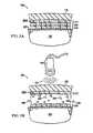
- FIG. 2Ais a cross-sectional view of a system for facilitating removal of a drape 125 from a tissue site 105 in accordance with an illustrative embodiment of the present invention
- FIG. 2Bis a cross-sectional view of a system for facilitating removal of a drape 125 from a tissue site 105 in accordance with an illustrative embodiment of the present invention
- FIG. 3Ais a cross-sectional view of a system for facilitating removal of a drape 125 from a tissue site 105 in accordance with an illustrative embodiment of the present invention
- FIG. 3Bis a cross-sectional view of a system for facilitating removal of a drape 125 from a tissue site 105 in accordance with an illustrative embodiment of the present invention
- FIG. 4is a block diagram of an apparatus for facilitating removal of a drape 125 from a tissue site 105 in accordance with an illustrative embodiment of the present invention
- FIG. 5is a flowchart illustrating a process for facilitating removal of a drape 125 from a tissue site 105 in accordance with an illustrative embodiment of the present invention.
- FIG. 6is a line plot showing load (N) as a function of extension (mm) for specimen 1 and specimen 2. Further details regarding methodology are provided in Example 1.
- Reduced pressuregenerally refers to a pressure less than the ambient pressure at a tissue site that is being subjected to treatment. In most cases, this reduced pressure will be less than the atmospheric pressure of the location at which the patient is located.
- vacuumand “negative pressure” can be used to describe the pressure applied to the tissue site, the actual pressure applied to the tissue site can be significantly less than the pressure normally associated with a complete vacuum. Consistent with this nomenclature, an increase in reduced pressure or vacuum pressure refers to a relative reduction of absolute pressure, while a decrease in reduced pressure or vacuum pressure refers to a relative increase of absolute pressure.
- the term “coupled”includes “indirect coupling” via a separate object.
- a drapecan be coupled to the tissue site if both the drape and the tissue site are coupled to one or more third objects, such as a release agent or a second adhesive layer.
- the term “coupled”also includes “directly coupled,” in which case the two objects touch each other in some way.
- the term “coupled”also encompasses two or more components that are continuous with one another by virtue of each of the components being formed from the same piece of material.
- the term “coupled”includes chemical coupling, such as via a chemical bond, and electrostatic coupling.
- Various aspects of the present inventioncomprise a system and method for facilitating removal of a drape 125 from a tissue site 105 , a portion of which is shown in each of the FIGS. 1-3 .
- Various embodimentscan facilitate the removal of the drape 125 from the tissue site 105 with less trauma to a patient than conventional drapes.
- the tissue site 105may be skin tissue, wound tissue, bone tissue, or any other type of tissue.
- Various embodiments of the system and method described hereincomprise, or can be used with, reduced pressure wound healing technology.
- various embodiments described hereincan be used in high-fluid transfer wound applications as can be found in, for example, some V.A.C. Instill® applications manufactured by Kinetic Concepts, Inc. (San Antonio, Tex.).
- the system 100comprises the drape 125 having an adhesive side 179 and an adhesive layer 177 coupled to the adhesive side 179 of the drape 125 .
- the adhesive layer 177adheres to the tissue site 105 thereby coupling the drape 125 to the tissue site 105 .
- the adhesive layer 177may cover any portion of the drape 125 and the tissue site 105 as may be required.
- the adhesive layer 177includes release agents comprising a release material 182 , which may be contained in microstructures.
- the weakened bond that occurs as a result of the release of release material 182allows a user of the drape removal facilitation system 100 to apply an upward force on drape 125 , such as a force indicated by arrow 186 , to remove drape 125 from tissue site 105 .
- the weakened bondreduces the stress applied to tissue site 105 in the removal of drape 125 from tissue site 105 .
- a residue of molecules from adhesive layer 177might remain on tissue site 105 after removal of drape 125 depending on a variety of factors such as the type of release agent used.
- release materials 182are inertly dispersed within adhesive layer 177 and are located at the interface between adhesive layer 177 and tissue site 105 . But release materials 182 can be located anywhere within adhesive layer 177 , as well as any of the outer surfaces of adhesive layer 177 , such as the interface between adhesive layer 177 and drape 125 . In some embodiments, release materials 182 can be bonded or coupled directly to drape 125 , and a separate film layer, not shown in FIG. 1A , can separate release materials 182 from adhesive layer 177 .
- the presence of an external stimulus 184can weaken, break-down, or increase the permeability of the separate film layer such that release materials 182 are allowed to migrate into adhesive layer 177 to facilitate the removal of drape 125 from tissue site 105 .
- Release materials 182 in FIG. 1Aare released in the presence of external stimulus 184 such that release materials 182 are allowed to migrate within adhesive layer 177 and the interface between adhesive layer 177 and tissue site 105 .
- drape removal facilitation system 100is shown according to an illustrative embodiment.
- drape removal facilitation system 100shows a non-limiting example of drape removal facilitation system 100 that is exposed to an external stimulus 184 .
- Source 188can emit external stimulus 184 .
- a presence of an external stimulus 184can cause microstructures containing release agents comprising a release material 182 to rupture or tear, thereby releasing release materials 182 from the interior of the microstructures.
- These released release materials 182can then be interspersed into adhesive layer 177 and the interface between adhesive layer 177 and tissue site 105 , thereby weakening the bond between drape 125 and tissue site 105 and facilitating the removal of drape 125 from tissue site 105 .
- the migration of release materials 182can form pores 183 at the surface of the adhesive layer 177 adjacent the tissue site 105 which facilitate the removal of drape 125 from tissue site 105 .
- FIG. 1Bshows pores 183 to be at or near the interface between adhesive layer 177 and tissue site 105
- pores 183can be located anywhere in adhesive layer 177 , including any surface of adhesive layer 177 .
- pores 183can be located at the interface between drape 125 and adhesive layer 177 .
- release materials 182comprise or form gas particles
- the presence of external stimulus 184causes the gas particles in adhesive layer 177 to be released from their inert state to form pores 183 , which can be filled with the gas particles.
- pores 183are formed as a result of either or both of the expansion or migration of the gas particles.
- the presence of external stimulus 184can also cause a reaction between at least two substances in adhesive layer 177 that generate the gas particles to form pores 183 .
- the release or generation of the gas particlescauses an increase in the porosity in adhesive layer 177 that facilitates the removal of drape 125 from tissue site 105 .
- pores 183can weaken the bond between the molecules within adhesive layer 177 . This weakening can be a result of the spatial separation of the molecules in adhesive layer 177 and tissue site 105 or can also be a result of the poor bonding qualities between the molecules in the gas particles and the molecules in adhesive layer 177 and tissue site 105 .
- release materials 182comprise oil particles
- the presence of external stimulus 184causes the oil particles in adhesive layer 177 to be released to form pores 183 , which can be filled with the oil particles.
- the presence of oil-filled pores 183weakens the bond between adhesive layer 177 and tissue site 105 .
- pores 183can prevent the molecules in adhesive layer 177 from bonding to tissue site 105 by spatially separating the molecules in adhesive layer 177 and tissue site 105 .
- the chemical composition of the oil particles in pores 183can be such that the molecules in adhesive layer 177 and tissue site 105 form little or no bond with the molecules in the oil particles.
- the presence of external stimulus 184can cause the microstructures to rupture such that release materials 182 are released in adhesive layer 177 to form pores 183 containing the release agent.
- the microstructurecan be composed of material that is weakened, destabilized, or cleaved by external stimulus 184 , thereby allowing release materials 182 contained in the microstructures to be released.
- release materials 182are contained by micelle microstructures
- the molecules forming the micellesuch as the surfactant molecules
- the molecules in the micelleare dissociated in the presence of external stimulus 184 that is ultrasound pulses in a range of 20 to 90 kilohertz.
- Release materials 182can also be released from the micelles by altering the permeability of the micelles.
- external stimulus 184can be light that affects the permeability of the micelles such that release materials 182 can exit the micelles. In this example, photo-oxidation of the micelle allows release materials 182 to be released.
- Drape removal facilitation system 200includes adhesive layer 277 on adhesive side 279 of drape 125 .
- drape removal facilitation system 200includes a release agent comprising a layer of linker material 295 .
- the layer of linker material 295is coupled to adhesive layer 277 via functional group 280 .
- Drape 125is adapted to be coupled to tissue site 105 via layer of linker material 295 .
- layer of linker material 295can be adapted to bond directly to tissue site 105 .
- FIG. 2Bdrape removal facilitation system 200 is shown according to an illustrative embodiment.
- FIG. 2Bshows a non-limiting example of drape removal facilitation system 200 that is exposed to an external stimulus 184 .
- External stimulus 184cleaves linker material 295 into cleaved linker material 296 .
- the bond between adhesive layer 277 and tissue site 105is weakened or broken to facilitate the removal of drape 125 from tissue site 105 .
- the adhesive layer 277retain functional groups 280 after cleavage of linker material 295 . Drape 125 can then be removed from tissue site 105 without undue stress being placed on tissue site 105 .
- FIG. 2Bshows a non-limiting example of drape removal facilitation system 200 that is exposed to an external stimulus 184 .
- External stimulus 184cleaves linker material 295 into cleaved linker material 296 .
- the bond between adhesive layer 277 and tissue site 105is weakened or broken to facilitate the removal of drape 125 from tissue
- external stimulus 184can be light that cleaves the photolabile linkers into cleaved linker material 296 . Because no adhesive layer is present between the layer of linker material 295 and tissue site 105 , little or no adhesive layer residue remains at tissue site 105 upon the removal of drape 125 from tissue site 105 .
- drape removal facilitation system 300is shown according to an illustrative embodiment.
- no external stimulusis being applied to drape removal facilitation system 300 .
- the portion of tissue site 105 showncan be skin tissue.
- the portion of tissue site 105 shown in FIG. 3Acan also include any other type of tissue, such as wound tissue or bone, as discussed further below.
- the drape removal facilitation system 300includes a first adhesive layer 377 and a second adhesive layer 378 .
- Second adhesive layer 378is adapted to bind to tissue site 105 .
- Drape removal facilitation system 300includes a release agent comprising a layer of linker material 295 .
- the layer of linker material 295does not bind directly to tissue site 105 , but rather, binds to functional group 280 in second adhesive layer 378 .
- one side of layer of linker material 295is bound to first adhesive layer 377 and another side of the layer of linker material 295 is bound to second adhesive layer 378 . In this manner, the layer of linker material 295 is sandwiched between first adhesive layer 377 and second adhesive layer 378 .
- drape removal facilitation system 300is shown according to an illustrative embodiment.
- drape removal facilitation system 300is exposed to an external stimulus 184 .
- External stimulus 184cleaves linker material 295 into cleaved linker material 296 .
- the bond between first adhesive layer 377 and second adhesive layer 378 via linker material 295is weakened or broken to facilitate the removal of drape 125 from tissue site 105 .
- the first adhesive layer 377 and second adhesive layer 378retain functional groups 380 after cleavage of linker material 295 .
- Drape 125can then be removed from tissue site 105 without undue stress being placed on tissue site 105 .
- all or a portion of second adhesive layer 378can remain at tissue site 105 upon the removal of drape 125 from tissue site 105 .
- the illustrative embodiments described in FIG. 1can be used in combination with the illustrative embodiments described in FIGS. 2-3 .
- release agentscomprising a release material 182 or microstructures containing release material 182 can be included in the illustrative embodiment described in FIGS. 2-3 .
- the presence of external stimulus 184can cleave linker material 295 and release release material 182 into the area between drape 125 and tissue site 105 .
- the cleaving of linker material 295can facilitate the migration of release material 182 in the area between drape 125 and tissue site 105 .
- the reduced pressure treatment system 400comprises a reduced pressure source 410 that provides a reduced pressure and dressing 415 connected to the reduced pressure source 410 via conduits 435 for delivering the reduced pressure to the tissue site 105 .
- the dressing 415comprises the drape 125 , a delivery conduit 445 , a connector 420 for supporting the delivery conduit 445 on the drape 125 , and a foam pad 110 for insertion into the wound portion 115 of the tissue site 105 .
- the drape 125seals the foam pad 110 within the wound portion 115 of the tissue site 105 allowing the delivery conduit 445 to communicate a reduced pressure to the foam pad 110 .
- the application of reduced pressure to tissue site 105can be used to promote the drainage of exudate and other liquids from tissue site 105 , as well as stimulate the growth of additional tissue.
- drape 125can be removed for any reason as determined by the patient or administrator of reduced pressure treatment system 400 according to compositions and methods described herein.
- Tissue site 105can be the bodily tissue of any human, animal, or other organism, including bone tissue, adipose tissue, muscle tissue, dermal tissue, vascular tissue, connective tissue, cartilage, tendons, ligaments, or any other tissue. While tissue site 105 can include a wound, diseased tissue, or defective tissue, the tissue site 105 can also be healthy tissue that is not wounded, diseased, or defective.
- the tissue site 105has a tissue surface 107 surrounding the wound portion 115 of the tissue site 105 to which the adhesive portion of the drape 125 , for example, adhesive layers 177 , 277 , 377 and 378 , adheres. The non-adhesive portion of the drape 125 covers the wound portion 115 of the tissue site 105 .
- the adhesive portion of the drapemay cover some or all of the wound portion 115 of the tissue site 105 or the foam pad 110 .
- the drape removal systems 100 , 200 , 300facilitate removal of the drape 125 because they require substantially less force as compared to a conventional drape. Such systems can tolerate the adhesive portion of drape 125 partially covering the wound portion 115 of the tissue site 105 that would be otherwise difficult or impossible to securely dress with conventional drapes.
- Drape 125can be configured to provide a sealed connection with the tissue surface 107 of the tissue site 105 surrounding the wound portion 115 .
- the sealed connectionis provided by any one of the adhesive layers 177 , 277 , 377 and 378 positioned along a perimeter of the drape 125 or on any portion of drape 125 to secure drape 125 to the tissue surface 107 of the tissue site 105 surrounding the wound portion 115 .
- the adhesive layerscan be pre-positioned on drape 125 or can be sprayed or otherwise applied to drape 125 immediately prior to installing drape 125 . Prior to the application of drape 125 to tissue site 105 , the adhesive can also be covered by an adhesive support layer.
- the adhesive support layercan provide rigidity to the drape 125 prior to application and can also aid in the actual application of drape 125 onto tissue site 105 .
- the adhesive support layercan be peeled off or otherwise removed before applying drape 125 to tissue site 105 .
- a portion of any one of the drape removal facilitation systems 100 , 200 , 300is shown and collectively referred to as drape removal systems 405 .
- Reduced pressure treatment system 400also includes a fluid collection apparatus 440 .
- Liquids from the wound portion 115 of the tissue site 105such as exudates, flow through delivery conduit 445 and the conduit 435 into fluid collection apparatus 440 via a connector 450 that also communicates the reduced pressure from the reduced pressure source 410 to the delivery conduit 445 .
- the reduced pressure treatment system 400can further include a volume detection system 457 to detect the amount of fluid present in fluid collection apparatus 440 ; a reduced pressure feedback system 455 ; a blood detection system 459 to detect the presence of blood in exudate drawn from the wound portion 115 of the tissue site 105 ; a temperature monitoring system 462 to monitor the temperature of tissue site 105 ; an infection detection system 465 to detect the presence of infection at tissue site 105 ; or a flow rate monitoring system 467 to monitor the flow rate of fluids drawn from tissue site 105 .
- reduced pressure treatment system 400can include valves, regulators, switches, and other electrical, mechanical, and fluid components to facilitate administration of reduced pressure treatment to the wound portion 115 of the tissue site 105 .
- the following sectionsdescribe components of the drape removal system 405 in more detail including the following: the drape 125 ; the adhesive layers 177 , 277 , 377 and 378 referred to collectively as adhesive layer 477 as shown in FIG. 4 ; a release agent 482 (not shown) comprising one or more of the release materials 182 , linker materials 295 , or any other similar materials; the release materials 182 ; microstructures; the linker materials 295 ; and the external stimulus 184 .
- a drape 125is generally understood to be a covering over a tissue site 105 .
- a drape 125can function to secure one or more components of the system to a tissue site 105 .
- a drape 125can secure an optional manifold to a tissue site 105 .
- a drape 125is preferably sterilizable.
- a drape 125can comprise a biocompatible thin film material, such as a polymer.
- a drape 125can comprise a woven or non-woven material.
- a drape 125can comprise an elastic or non-elastic material.
- a drape 125can comprise a flexible or inflexible material.
- a drape 125 of inflexible materialcan be molded for a particular tissue site 105 .
- the drape 125is a soft, flexible material having skin-like conformability.
- a drape 125can comprise an impermeable, semi-permeable, or permeable material. Permeability characteristics can be selected according to desired moisture and gas (e.g., oxygen) transmission. In some embodiments, the drape 125 comprises a material relatively impermeable to moisture and relatively permeable to oxygen. A drape 125 can be coated with a material, for example, to control breathability. A drape 125 can comprise an occlusive or nonocclusive material. An occlusive dressing can be desirable to increase uptake of a therapeutic agent supplied to a tissue site 105 .
- a drape 125can comprise a material which allows or facilitates transmission of external stimuli, such as light, sound, moisture or heat.
- a drape 125 materialcan be semi- or substantially transparent to electromagnetic radiation, such as visible, ultraviolet, or infrared light.
- a drape 125 materialcan facilitate transmission of ultrasonic energy.
- Fiber containing materialsare often opaque due to the light scattering effect of the fibers. The scattering can be reduced by impregnating the fiber-containing material with another material of similar refractive index (as the fibers) to provide semi- or substantially translucent or transparent material better able to transmit electromagnetic radiation, such as visible, ultraviolet, or infrared light.
- Relatively “simple” polymerssuch as a polyolefin, having few active chemical species can absorb less electromagnetic radiation, such as visible, ultraviolet, or infrared light, than such polymers as polyurethane, polyester, & polyamide, which have significant levels of active chemical groups (e.g. amine, ester, carboxyl, hydroxyl, ether, aromatic, and double bond saturation).
- active chemical groupse.g. amine, ester, carboxyl, hydroxyl, ether, aromatic, and double bond saturation.
- Materials of a drape 125can be selected so as to promote one or more of stemming bleeding, absorbing exudate, easing pain, debriding a wound, controlling moisture content, controlling rate of absorption of a topical medicament, maintaining pH, maintaining temperature, protecting from infection, indicating increased bioburden levels, and promoting healing.
- a drape 125preferably comprises a biocompatible material that includes the impermeability or permeability characteristics desired or necessary for a tissue site 105 .
- a drape 125can be formed of a hydrophobic material to prevent moisture absorption by the drape 125 .
- a drape 125can take the form of, for example, a film, gel, foam, paste, granule, or bead.
- a drape 125can be in sheet form.
- a drape 125can be in a flowable form suitable for pouring or dispensing by other means known in the art.
- a drape 125can be in a sprayable form.
- a drape 125can be applied after or simultaneously with other system components such as a manifold or an adhesive layer 177 .
- a drape 125can be composed of materials including, but not limited to, polyurethane, polyether, polyester, polyolefin, polyolefin sintered polymer, silicone based compound, acrylic, alginate, hydrocolloid, hydrogel, hydrogel-forming material, polysaccharide, natural fabric, synthetic fabric, polyvinyllchlorides, polyamides, polyethyl eneglycolpolydimethyl diloxan co-polymers, polyphosphazenes, cellulosic polymers, chitosan, PVdF, EVA sintered polymer, PTFE, thermoplastic elastomers (TPE), or combinations thereof.
- a drape 125comprises a thin film biocompatible polymer.
- Combinationscan be polymeric combinations, layered combinations, or both.
- the drape 125can comprise an EVA sintered polymer.
- the drape 125can comprise Tyvek (PE), especially in the function of a protective cover.
- PETTyvek
- Commercially available exemplary drape 125 materialsinclude, but are not limited to, Avery Dennison Med 5625; 3M Ioban2; 3M Steri-Drape 125 2; Nitto Denko Yu-Kiban Perme; 3M Tegaderm; First Water Hydroskin; Opsite; Exopack (a polyurethane film and adhesive); Bayer (a polyurethane film); DuPont (an etherester film).
- a drape 125can be composed of one or more layers.
- a drape 125can be a bilayer drape 125 .
- a bilayer drape 125can comprise a first layer comprising any biocompatible thin film suitable for tissue or wound contact and a second layer comprising a protective material, such as moisture resistant Tyvek (PE).
- PEmoisture resistant Tyvek
- a drape 125can comprise a (second layer) coating to control breathability.
- Three, four, or more drape 125 layersare contemplated, with combinations of materials selected according to desired function.
- the drapecan comprise zones of the same or different materials. For example, within the same plane, multiple zones can comprise differing drape 125 material.
- a drape 125can include both a laminate structure comprising a plurality of drape 125 materials and multiple zones of materials within the same plane.
- a drape 125can be manufactured by laminating an adhesive-coated flexible film, such as a polyurethane film, to a protective releasable layer, such as a siliconized paper.
- a strengthening layer of thicker plastic materiale.g. a polyolefin such a polyethylene, can be applied to a non-adhesive coated face of the flexible film, so that a three-layer laminate is produced.
- a laminatecan be produced in a substantial width and can be slit longitudinally to a desired width and then laterally to form a drape 125 of desired dimensions.
- Handling barscan be applied to an adhesive-coated layer at one or both lateral edges to facilitate separation of the film from the protective, releasable layer.
- a drape 125is able to maintain a reduced pressure at a tissue site 105 after installation of the drape 125 . At any time before, during, or after the application of reduced pressure to a tissue site 105 , a drape 125 can be removed for any reason as determined by the patient or caregiver.
- a drape 125can include a device that provides sealing functionality.
- a drape 125can include a suction cup, a molded cast, or a bell jar.
- Such devices, or other devices providing sealing functionalitycan be applied over other components of the system, such as the manifold, dressing, adhesive layer 177 , or other portions of the drape 125 .
- a drape 125can be configured to provide a sealed connection with tissue surrounding the system, or components thereof, and the tissue site 105 .
- a sealed connectioncan be provided by an adhesive layer 177 positioned along a perimeter of a drape 125 or on any portion of drape 125 so as to secure the drape 125 to other components of the system (e.g., manifold), tissue surrounding the tissue site 105 , or combinations thereof.
- the systemcan include an adhesive layer 477 .
- the adhesive layer 477can function to secure one or more components of the system, such as a drape 125 , to a tissue site 105 .
- the adhesive layer 477is preferably located on the drape 125 , such as an adhesive side of the drape 125 .
- An adhesive layer 477can be adapted to bind to a tissue site 105 .
- An adhesive layer 477can comprise any material, in single or multiple layers, capable of adhering to a surface, such as a tissue site 105 .
- a drape 125is bound to a tissue site 105 via an adhesive layer 477 .
- an adhesive layer 477can be pre-applied to an adhesive side of a drape 125 prior to application to a tissue site 105 .
- An adhesive layer 477can cover an entire surface of a drape 125 or only a portion of a of a drape 125 .
- an adhesive layer 477can cover a portion of the adhesive side of a drape 125 .
- Adhesive covered portionscan form any suitable shape.
- an adhesive layer 477can form a circle, square, or strip across a drape 125 such that only those portions of a drape 125 covered by an adhesive layer 477 are adapted to adhere to a tissue site 105 .
- An adhesivecan be pre-positioned on a drape 125 or can be sprayed or otherwise applied to the drape 125 prior to installation. Prior to the application of a drape 125 to a tissue site 105 , the adhesive can also be covered by an adhesive support layer.
- the adhesive support layercan provide rigidity to the drape 125 prior to application and can also aid in the actual application of drape 125 onto tissue site 105 .
- the adhesive support layercan be peeled off or otherwise removed before applying a drape 125 to a tissue site 105 .
- An adhesive layer 477can comprise a material capable of adhering to a surface, such as a tissue site 105 or other component of the system.
- An adhesive layer 477can comprise one or more materials including, but not limited to, polyurethane, acrylic (e.g., cyanoacrylate), hydrogel, silicon or silicone based material, natural rubber, synthetic rubber, styrene block copolymers, polyvinyl ethers, poly(meth)acrylates, polyolefins, hydrocolloid (e.g., a rubber based hydrocolloid), or a combination thereof.
- the adhesive layer 477comprises a polymer or co-polymer.
- the adhesive layer 477can comprise a co-polymer of polyurethane and silicone or various acrylic co-polymers.
- An adhesive layer 477can have any thickness suitable to facilitate securing the system, or components thereof, to a tissue site 105 or surrounding tissue.
- an adhesive layer 477can have a thickness of about 0.1 mm to about 50 mm. Thickness of an adhesive layer can depend upon adhesive contained therein.
- an acrylic and rubber containing adhesive layercan have a thickness of about 0.5 mm to about 5 mm, preferably about 1 mm to about 2 mm.
- a silicone gel containing adhesive layercan have a thickness of about 4 mm to about 15 mm.
- a hydrogel containing adhesive layercan have a thickness of about 10 mm to about 40 mm.
- a hydrocolloid containing adhesive layercan have a thickness of about 4 mm to about 40 mm, preferably about 10 mm to about 40 mm. Thickness can further vary according to additional components of the adhesive layer. For example, a V.A.C. hydrogel with PEG can have a thickness of about 3 mm to about 4 mm. A relatively thicker adhesive layer 477 can allow for the presence of more microstructures or release agents 182 or larger microstructures. An adhesive layer 477 can have a uniform thickness or a non-uniform thickness.
- a residue of molecules from an adhesive layer 477can or can not remain on a tissue site 105 after removal of a drape 125 depending on a variety of factors, including, but not limited to, the location of pores, the type of release agent used, or the particular embodiment implemented. In some embodiments, no residue of molecules from an adhesive layer 477 remain on a tissue site 105 after removal of a drape 125 .
- an adhesive support layercan be covered by an adhesive support layer.
- the adhesive support layercan be removed prior to the application of a drape 125 to a tissue site 105 .
- the adhesive support layercan provide rigidity to a drape 125 prior to application.
- the adhesive support layercan facilitate in the actual application of a drape 125 onto a tissue site 105 .
- an adhesive support layercovers only a portion or portions of a drape 125 covered, in whole or in part, by an adhesive layer 477 .
- an adhesive support layercan cover portions of a drape 125 covered by an adhesive layer 477 and portions not covered by an adhesive layer 477 .
- An adhesive support layercan comprise a single segment or a plurality of segments, each covering a different portion of a drape 125 or adhesive layer 477 .
- An adhesive support layercan serve to protect a drape 125 , an adhesive layer 477 , a release material 182 , or a linker material 295 , or a combination thereof, from an external stimuli.
- An adhesive support layercan protect a drape removal system from an external stimulus 184 that can cause release or activation of a release material 182 or cleavage of a linker material 295 .
- an adhesive support layercan be chosen so as to block transmission of light.
- the systemincludes an adhesive tape.
- the adhesive tapecan include a backing layer and an adhesive layer 477 .
- An adhesive tapecan be used to hold primary or secondary dressings in place.
- An adhesive tapecan serve a function as both a tissue site cover and adhesive layer 477 thereof.
- a backing layer of an adhesive tapecan comprise a material such as those discussed above in the context of a drape 125 .
- the backing layer of the adhesive tapecomprises cloth, polyurethane, or non-woven materials.
- Fiber containing materialsare often opaque due to the light scattering effect of the fibers.
- the scatteringcan be reduced by impregnating the fiber-containing material with another material of similar refractive index (as the fibers) to provide semi- or substantially translucent or transparent material better able to transmit electromagnetic radiation, such as visible, ultraviolet, or infrared light.
- Relatively “simple” polymerssuch as a polyolefin, having few active chemical species can absorb less electromagnetic radiation, such as visible, ultraviolet, or infrared light, than such polymers as polyurethane, polyester, & polyamide, which have significant levels of active chemical groups (e.g. amine, ester, carboxyl, hydroxyl, ether, aromatic, and double bond unsaturation).
- active chemical groupse.g. amine, ester, carboxyl, hydroxyl, ether, aromatic, and double bond unsaturation.
- a release agent 482 comprising a release material 182can facilitate removal of a drape 125 from a tissue site 105 .
- the release agent 482can physically or chemically affect adhesion characteristics between a drape 125 and a tissue site 105 .
- Release agentscan be present in an inert or inactive form in, on, or near an adhesive layer 477 .
- a release agent 482can be mixed with the adhesive; on the surface of the adhesive with a random or patterned coverage; coupled to the drape 125 with a random or patterned coverage; or contained within a microstructure located in these or other locations.
- release agents 482can migrate within the adhesive layer 477 or along an interface between an adhesive layer 477 a tissue site 105 to facilitate the removal of a drape 125 affixed thereto.
- Techniquessuch as differential scanning calorimetry (DSC), rheometry, a mechanical tensile test device can be used to optimize levels of release agents in or on the adhesive layer 477 .
- the release agentcomprises a release material 182 .
- Release material 182can be inertly dispersed within an adhesive layer 477 .
- Release material 182can be located at the interface between an adhesive layer 477 and a tissue site 105 . It is contemplated that a release material 182 can be located anywhere within an adhesive layer 477 , as well as any outer surface of an adhesive layer 477 , such as an interface between the adhesive layer 477 and drape 125 .
- a release material 182can comprise a microstructure.
- a release material 182can form a microstructure.
- a release material 182can be encapsulated in a microstructure. Suitable microstructures can be as discussed below.
- a release material 182can be a component of an adhesive of the adhesive layer. Where a release agent functions to chemically interfere with, weaken, or otherwise disrupt a bond, it is usually comprises a linker material 295 .
- a release material 182can released in the presence of an external stimulus 184 , as discussed further below.
- release material 182is bound to an adhesive layer 477 in an absence of any external stimulus 184 that is capable of weakening or breaking the bond between the release material 182 and adhesive layer 477 .
- a release material 182can be bound to an adhesive layer 477 via a chemical bond or by virtue of physically abutting the adhesive layer 477 .
- a release material 182is mixed into an adhesive layer 477 .
- a release material 182can be bonded to the drape 125 .
- a release material 182can be coupled to a drape 125 .
- a separate film layer of the drape 125can release a release material 182 from an adhesive layer 477 .
- the presence of an external stimulus 184can weaken, break-down, or increase the permeability of a separate film layer such that release agents 482 are allowed to migrate into the adhesive layer 477 to facilitate the removal of the drape 125 from a tissue site 105 .
- the systemincludes a plurality of release materials 182 bound to the adhesive layer 477 that are released in the presence of the external stimulus 184 to facilitate removal of the drape 125 from the tissue site 105 .
- the systemincludes a first adhesive layer 477 on the adhesive side of the drape 125 .
- the systemcan also include a plurality of linker materials 295 coupled to the first adhesive layer 477 .
- the drape 125can be adapted to be coupled to the tissue site 105 via a plurality of linker materials 295 .
- the plurality of linker materials 295can be weakened in the presence of the external stimulus 184 to facilitate removal of the drape 125 from the tissue site 105 .
- a release material 182can function, for example, according to chemical or physical interaction with an adhesive or other component of the system.
- a release material 182can react with an adhesive, with itself, or with some other component of the system so as to change the character of the drape 125 adhesion to the tissue site 105 .
- a release material 182can react, resulting in hardening (e.g., through crosslinking), softening (e.g., oxidation degradation, chain scission), or dissolving (e.g., release of solvent) of the adhesive layer, the drape, or the release agent itself.
- a release material 182can physically interact with an adhesive.
- a release material 182can, for example, stimulate a cohesive fracture, interfacial fracture, mixed fracture, or alternating crack path fracture in the adhesive layer. Release of a release material 182 can form pores that facilitate the removal of a drape 125 from a tissue site 105 .
- a release material 182can react so as to form bubbles, thereby pushing the adhesive away from a tissue site 105 .
- a release material 182can comprise a variety of molecular compositions depending on the particular embodiment being implemented.
- a release material 182can comprise a sub-ambient T g material. Where a release material 182 comprises a sub-ambient T g material, cooling the system can trigger drape release.
- a sub-ambient T g materialcan be incorporated into or onto the adhesive layer. Upon cooling, a sub-ambient T g material can crystallize, thereby introducing brittleness to disrupt an adhesive layer, thereby facilitating removal of the drape 125 .
- Examples of a sub-ambient T g materialinclude, but are not limited to, Evonik Degussa DYNAPOL® LH 538 Polyester Resin; Evonik LTW adhesion resin; Loctite Durabond E-OOCL epoxy adhesive; and Loctite Durabond E-OONS epoxy adhesive.
- a release material 182can comprise a photopolymer.
- a photopolymerized release agentcan be incorporated into or onto the adhesive layer 477 . Photoinitiation of polymerization can result in a hard brittle material that can interfere with the adhesive layer 477 , thereby facilitating removal of the drape 125 .
- a photopolymerizable release agentis bisphenol glycidylmethacrylate. Additional release agent components can include, but are not limited to, diluents, crosslinkers, coupling agents, free radical initiators, chemical accelerators, and plasticizers.
- a release material 182can comprise an oil particle.
- release materials 182include, but are not limited to, natural oils, synthetic oils, surfactants, silicone particles, paraffin particles, fluorocarbon particles, vitamin E, glycerin, glycerol, olive oil, safflower oil, sesame oil, tea tree oil, stearic acid, glycery stearate, retinyl palmitate, allantoin, soy esters or other appropriate esters, d-limonene or other appropriate terpenes, or a particle having a low melting point, or combinations thereof.
- the release of such particles in the presence of an external stimulus 184can cause the bond between a drape 125 and a tissue site 105 to weaken, thereby facilitating the removal of the drape 125 .
- a release material 182can comprise a solvent.
- a solventcan dissolve an adhesive so as to ease removal.
- Solvent release agentscan be selected to minimize concerns of toxicity and adhesive residue.
- Examples of a solvent release agentinclude, but are not limited to, DMSO; IPA; ethyl acetate; and polyethylene glycol.
- a solvent release agentis tetrahydrofurfuryl acetate to facilitate removal of a cyanoacrylate dermal adhesive.
- a release material 182can comprise a lipid.
- a lipid release agentWhen released (e.g., melted), a lipid release agent can interfere with a bond between a tissue site and an adhesive.
- a lipidcan be encapsulated within a microstructure or itself form a microstructure (e.g., a solid lipid nanoparticle).
- An example of a lipid release agentis solid lipid particles (Trilaurin with 0.01% Brij 78, with m.p. 45-47° C., average particle size 6.5 ⁇ m). Particle size of a solid lipid can be modulated through, for example, different emulsification techniques.
- release materials 182include, but are not limited to: thermally degrading adhesives (e.g., high degree of Diels-alder adducts, heat to react); Gecko mimics (e.g., polyvinylsiloxane microscale pillars, carbon nanotubes, coated PDMS micropatterns, rippled PDMS films); ultrasonic degraded compounds (e.g., alkoxylate acrylate, pharma fillers, ultrasonics of about 20 kHz); thermally reversible adhesives; mussel adhesive proteins (e.g., mimics of mussel adhesion); polymer brushes (e.g., tethered polymer chains); solvent induced switching (e.g., polymer brushes, PS, PVP); magnetic on/off (e.g., MEMS device with cantilevered nanostructures moveable with a magnetic field); and silicone gel.
- thermally degrading adhesivese.g., high degree of Diels-alder a
- release material 182include any of the materials discussed below in the context of linker materials, where an external stimulus causes the polymer to react in such a way as to cause a physical disruption of the adhesive layer (i.e., the polymer material polymerizes so as to form a physical structure that interferes with the adhesive, rather than depolymerizing so as to disrupt adhesive bonds).
- a release material 182can comprise a gas particle.
- release materials 182include, but are not limited to, nitrogen, helium, hydrogen, carbon dioxide, oxygen, and fluorocarbons, such as chlorofluorocarbons.
- a volatile liquid (e.g., hydrocarbon) or gascan be encapsulated in a microstructure; when exposed to an external stimulus 184 , such as a solvent or heat, the gas can be liberated.
- the gas particlescan be generated by a reaction between at least two substances, such as another release material 182 , a linker material 295 , or an adhesive material.
- gas particlescan be formed by a reaction between a linker material 295 and a material of the adhesive layer 477 .
- Such a reactioncan occur in the presence of an external stimulus 184 , such as those described herein.
- an oxygen release agentcan be produced from urea hydroperoxide via low pH or a solvent (e.g., an alcohol).
- a carbon dioxide release agentcan be produced upon exposure of a mixture of tartaric acid and bicarbonate to water.
- calcium carbonate and citric acidcan be separately encapsulated within a hydrogel microstructure and upon being release can form bubbles.
- the release or generation of gas particlescan cause an increase in the porosity of an adhesive layer 477 , thereby weakening a bond between a drape 125 and a tissue site 105 . Such weakening of an adhesive layer 477 can facilitate the removal of a drape 125 from a tissue site 105 .
- a microstructurecan serve as a delivery vehicle for a release agent.
- the systemincludes a plurality of microstructures bound to the adhesive layer 477 .
- a release material 182can be encapsulated in material of the microstructure, which can be embedded in or on the drape 125 where the microstructure remains dormant during drape 125 storage and application.
- a microstructurecan contain one or more release materials 182 that are released in a presence of an external stimulus 184 . Such release triggered by an external stimulus 184 can facilitate removal of a drape 125 from a tissue site 105 .
- a microstructurecan comprise a material that is weakened, destabilized, or cleaved by an external stimulus 184 , thereby allowing a release material 182 contained in the microstructures to be released.
- a microstructurescan be any shape, such as a sphere, prism, polygonal prism, cylindrical, or a bi-layer sheet in any of a variety of configurations. Microstructures can be uniformly or non-uniformly arranged. In one example, microstructures are located only in one or more designated zones of an adhesive layer 477 . Such designated zones can form a shape, such as a circle, square, or stripe, in the adhesive layer 477 . In some embodiments, microstructures are arranged equidistant from one another to form a grid-like matrix. In other embodiments, microstructures are configured to form an irregular pattern in which microstructures are not equidistant from one another. In further embodiments, microstructures are organized into a grid-like matrix in some regions and an irregular pattern in other regions.
- a microstructurecan comprise one or more carriers including, but not limited to, a polymeric delivery system, a microsphere, a polymeric hydrogel, a “smart” polymeric carrier, and a liposome.
- a microstructurecan be composed of one or more materials including, but not limited to, natural polymers, such as collagen, polysachharides, and N-acetyl-glcosamines; synthetic polymers, such as silicone, latex, poly-lactide-co-glycolide, polyethylene vinyl-co-acetate, and polyanhydrides; polyvinyl alcohol; polyphosphazene; PLA; PLGA; PLGA coated with DPPC, DPPC, DSPC, or EVAc; gelatin; albumin; chitosan; dextran; cyclodextran; DL-PLG SDLMs; PEG (e.g., ProMaxx); sodium hyaluronate; a diketopiperazine derivative (e.g., Technosphere);
- a microstructurecomprises at least two substances, such as acrylic polymer and a photoinitiator, such that in the presence of light, the acrylic polymer crosslinks, including shrinkage, stress, and fracture.
- a microstructurecomprises a cyclodextrin, where the cyclodextrins can absorb and bind a release material 182 , such as an oil particle, and then release the release material 182 upon being exposed to heat.
- a microstructurecan comprise a polymeric delivery system comprising a natural polymer, such as collagen, or a synthetic polymer, such as silicone, poly-lactide-co-glycolide, polyethylene vinyl-co-acetate, or a polyanhydride.
- a microstructurecan comprise a microsphere comprising PLA, PLGA, PLGA coated with DPPC, DPPC, DSPC, EVAc, gelatin, albumin, chitosan, dextran, DL-PLG, SDLMs, PEG, sodium hyaluronate, a diketopiperazine derivative, a calcium phosphate-PEG particle, or an oligosaccharide derivative.
- a microstructurecan comprise a polymeric hydrogel comprising a hydrophillic polymer such as collagen, fibrin, and alginate.
- a smart polymeris generally understood to be a polymeric material that can change properties through the application of an external trigger.
- a microstructurecan comprise so called “smart” polymeric carriers having pH-sensing functionality, such as a polyalkylacrylic acid polymer where pH profile can be controlled by the choice of the alkylacrylic acid monomer and by ratio of the carboxylate-containing alkylacrylic acid monomer to alkylacrylate monomer.
- a smart polymers for use as a microstructure materialincludes sub-ambient T g materials (e.g., Loctite; Evonik), which can provide brittleness to an adhesive once cooled below room temperature.
- T g materialse.g., Loctite; Evonik
- Another example of a smart polymers for use as a microstructure materialincludes photocrosslinked dental composites, which can provide brittleness to an adhesive once exposed to UV light.
- a microstructurecan comprise a liposome (e.g., a reactive/polymorphic pH sensitive liposome) comprising one or more lecithins, such as phosphatidylcholines, phosphatidylethanolamines, sphingomyelins, phosphatidylserines, phosphatidylglycerols, and phosphatidylinositols.
- a liposomee.g., a reactive/polymorphic pH sensitive liposome
- lecithinssuch as phosphatidylcholines, phosphatidylethanolamines, sphingomyelins, phosphatidylserines, phosphatidylglycerols, and phosphatidylinositols.
- the microstructureitself comprises a release agent.
- a release material 182 of vitamin Ecan be provided in the form of liposomes (e.g., Florasomes, a vitamin E liposome from Floratech).
- a microstructureis configured to be disrupted with the presence of an external stimulus 184 , such as those described herein.
- a microstructurecan be configured to rupture or tear upon exposure to an external stimulus 184 , thereby releasing a release material 182 from the interior of the microstructure.
- These released release materials 182can be dispersed or interspersed into or onto an adhesive layer 477 or the interface between an adhesive layer 477 and a tissue site 105 , thereby weakening a bond between a drape 125 and the tissue site 105 and facilitating the removal of the drape 125 from the tissue site 105 .
- a microstructurecan be bonded to an adhesive layer 477 by one or more linker materials 295 , as described more fully below.
- a microstructurecan be physically embedded in an adhesive layer 477 without requiring the presence of a linker material 295 . It is also contemplated that an adhesive layer 477 can comprise embedded microstructures not bound to a linker material 295 as well as microstructures bonded to the adhesive layer 477 by one or more linker materials 295 .
- a microstructurecomprises a micelle.
- a micelleis understood to be is an aggregate of surfactant molecules usually dispersed in a liquid colloid that can form a shape, such as a sphere.
- a micellecan be approximately spherical, ellipsoid, cylindrical, or bilayered.
- a wall of a micelleis generally composed of adjacent micelle molecules, such as surfactant molecules.
- surfactantsWhen surfactants are present above a critical micelle concentration, the surfactants can act as an emulsifier that will allow a compound, such as a release agent, normally insoluble (in the solvent being used) to dissolve.
- a micellecan form an aggregate with hydrophilic “head” regions in contact with surrounding solvent, sequestering the hydrophobic tail regions in the micelle centre, otherwise known as normal phase micelle or oil-in-water micelle.
- a release material 182is hydrophillic
- an inverse micellesi.e., a water-in-oil micelle
- Examples of the compounds or compositions from which a wall of a micelle can be composedinclude, but are not limited to, polyethylene glycol (PEG), pluronics, phospholipids, lecithin, casein, a non-ionic surfactant, such as Brij 35, and mixed micelles consisting of ionic surfactants such as sodium dodecyl sulfate and non-ionic surfactants such as dodecyl maltoside.
- PEGpolyethylene glycol
- pluronicsphospholipids
- lecithincasein
- a non-ionic surfactantsuch as Brij 35
- mixed micellesconsisting of ionic surfactants such as sodium dodecyl sulfate and non-ionic surfactants such as dodecyl maltoside.
- molecules forming the micellecan be dissociated in the presence of an external stimulus 184 , thereby causing a rupture that allows a release material 182 to be released.
- molecules of a micelleare dissociated in the presence of an external stimulus 184 comprising ultrasound pulses in a range of 20 to 90 kilohertz.
- a release material 182can be released from the micelles by altering the permeability of the micelles.
- an external stimulus 184such as light can effect a change (e.g., photooxidation) in the permeability of a micelle such that a release material 182 can exit the micelle.
- a microstructurecan be a coated microstructure.
- a coating of a microstructurecan provide structural reinforcement, improve integration with another component of the system, enhance stability, or other desirable functions.
- a microstructurecan be modified so as to provide a structural feature that facilitates integration with another component of the system, such as bonding with an adhesive of the adhesive layer 477 .
- the release agent 482comprises a linker material 295 .
- a linker material 295is one or more molecules capable of bonding to another component of the system, such as a release material 182 or adhesive, or coupling other components. Bonding of a linker material 295 can be covalent bonding or ionic bonding. Disruption of a linker material 295 can facilitate removal of a drape from a tissue site, usually by disruption adhesive bonds.
- a release material 182is bonded to an adhesive layer 477 by linker material 295 .
- a linker material 295couples a release material 182 or microstructure and an adhesive layer 477 .
- a linker material 295 and a release material 182can be contained in the adhesive layer 477 .
- a linker material 295can be bound to a second adhesive layer 477 .
- a linker material 295can couple a first adhesive layer 477 and a second adhesive layer. In this manner, a linker material 295 can be sandwiched between adhesive layers, allowing such layers to easily separate upon disruption of the linker material 295 .
- Molecules of which an adhesive layer 477 is composedcan have functional groups that chemically bond to a linker material 295 .
- a drape 125can be adapted to be coupled to a tissue site 105 via a linker material 295 .
- a linker material 295can be adapted to bond directly to a tissue site 105 .
- a linker material 295can bond to a tissue site 105 via an electrostatic force or by virtue of a pH difference between any of an adhesive layer 477 , linkers 295 , and a tissue site 105 .
- Examples of linker materials 295 capable of bonding directly to a tissue site 105include, but are not limited to benzoin derivatives and hydrogels. In embodiments where no adhesive layer 477 is present between a linker material 295 and a tissue site 105 , little or no adhesive layer residue remains at a tissue site 105 upon removal of a drape 125 .
- Bonding between a linker material 295 in the adhesive layer 477 and a release material 182can render the release material 182 inert or immobile such that release material 182 do not weaken the adhesion between adhesive layer 477 and tissue site 105 .
- a release material 182can be prevented from acting prematurely.
- linker material 295can be weakened or broken by exposure to an external stimulus 184 , thereby facilitating removal of the system.
- a linker material 295can become weak, unstable, or cleaved in the presence of external stimuli, such as light, sound, pressure, heat, and fluids, described further below.
- a linker material 295 of the drape removal facilitation systembecomes weak, unstable, or cleaved when exposed to an external stimuli that is not likely to cause an unintended release of release material 182 , such as light of a particular wavelength or sound of a particular frequency that is not typically present during reduced pressure treatment.
- a linker material 295can comprise a variety of molecular compositions depending on the particular embodiment being implemented.
- An example of a linker material 295includes, but is not limited to, a benzoin derivative.
- a linker material 295can be composed of polymer molecules. The linker polymer molecule can be part of the adhesive itself.
- a linker material 295can be hydrophobic, which can maintain the integrity of the seal between a drape 125 and a tissue site 105 .
- a linker material 295can comprise a photolabile linker.
- Photolabile linkersare one or more molecules that weaken or break-down in the presence of electromagnetic energy, such as visible, ultraviolet, or infared light.
- a photolabile linkerin an absence of electromagnetic energy, can be bound to a release material 182 so as to make the release material 182 inert or immobile.
- Various types of photolabile linkerscan be used depending on the particular embodiment being implemented.
- a particular photolabile linkercan be chosen based on the frequency of light at which the photolabile linker becomes weak, unstable, or is cleaved.
- a photolabile linkerbecomes weak, unstable, or is cleaved when exposed to electromagnetic radiation having wavelengths that are not substantially detrimental to skin tissue. Such wavelengths can include visible wavelengths, some infrared wavelengths, and some longer ultraviolet wavelengths, as understood in the art.
- photolabile linkersinclude, but are not limited to, dimethoxybenzoin, dimethylproprionic acid, 3,5-dimethoxybenzyl acetate, and 4-(2-chloroproprionyl)phenyl acetic acid.
- the photolabile linkersare dimethoxybenzoin
- light having a wavelength of approximately 365 nanometerscan be used to weaken or cleave a linker material 295 .
- the photolablile linkersare 3,5-dimethoxybenzyl acetate
- light having a wavelength of approximately 254 nanometerscan be used to weaken or cleave a linker material 295 .
- a linker material 295can comprise a light reversible polymer.
- a light reversible polymerinclude, but are not limited to dimerization of coumarin moieties as side chains.
- a linker material 295can comprise a thermo-responsive polymer.
- thermo-responsive polymersinclude, but are not limited to, poly(N-isopropylacrylamide) (NIPAM); poly(ethylene oxide) (PEO); and poly(propylene oxide) (PPO).
- a linker material 295can comprise a shape memory polymer (SMP).
- SMPsinclude, but are not limited to, poly(N,N′-methylenebisacrylamide) and oligo( ⁇ -caprolactone)dimethylacrylate.
- a release material 182can comprise a reversible SMP. Examples of a reversible SMP include, but are not limited to, reversible bonding of epoxy based SMP at 50° C.
- a linker material 295can comprise a pH sensitive polymer.
- a pH sensitive polymerinclude, but are not limited to, poly(methacrylic acids); phospholipids; and silicon-based polysilamine gels.
- a linker material 295can comprise an analyte sensitive polymer.
- an analyte sensitive polymerinclude, but are not limited to, non-enzymatic degradation; insulin/glutathione; and enzymatic sensitive crosslinkers.
- a linker material 295can comprise a photocrosslinker.
- a photocrosslinkerinclude, but are not limited to, disialyllacto-N-tetraose (DSLNT) and dental composites.
- an applied external stimulus 184facilitates removal of a drape 125 of the system.
- Various external stimulus 184can be employed depending on the particular embodiment being implemented.
- Non-limiting examples of the external stimulus 184include electromagnetic (e.g., ultraviolet, visible, or infared light), magnetic, sound, pH, pressure (e.g., positive atmospheric pressure, negative atmospheric pressure, shear force, direct force), thermal, moisture, or a substance.
- External stimulus 184can also be a substance, compound, liquid, or gas capable of reacting with a release material 182 or a linker material 295 in adhesive layer 477 such that the release material 182 is released.
- An external stimulus 184can disrupt microstructures of the system.
- An external stimulus 184can directly or indirectly cause a release material 182 to be released. Disruption of microstructures, disruption of a linker material 295 , or release of a release material 182 can facilitate removal of a drape 125 from a tissue site 105 .
- a thermal stimulican melt a shell of a microstructure or cause material expansion (of the microstructural material or encapsulated payload), thereby rupturing the shell and releasing the contents.
- Thermal stimuluscan be preferred for an acrylic adhesive, solvent release agent, or release agent dependent on crosslinking, or combinations thereof.
- Thermal stimuluscan be direct heat or indirect heat. The use of indirect heat can be less damaging to the surrounding tissue.
- a magnetic stimulican take advantage of an oscillating magnetic field to generate heat for an indirect thermal release mechanism of release.
- an oscillating magnetic fieldcan be used to introduce heat into the lipid.
- Electromagnetic stimulisuch as laser light or high intensity light sources, can be used to induce photooxidative weakening of the microstructure material or to generate heat for an indirect thermal release mechanism of release.
- Mechanical stimulican rely on the application of pressure to break a microstructure. But a microstructure must be durable enough to withstand adhesive application and normal use without prematurely rupturing.
- an external stimulus 184disrupts a microstructure of the system, allowing escape or activation of a release agent.
- an ultrasonic external stimulus 184can disrupt release agent-containing micelles located with the adhesive layer 477 , resulting in release materials 182 exiting the micelle.
- exposure to light as an external stimulus 184can cause photooxidation of a micelle, allowing escape of a release material 182 contained therein.
- exposure to light as an external stimulus 184can excite a wavelength specific nanorod release agent.
- heat, pressure, or the addition of a substancecan be used to dissociate a micelle molecules allowing contained release materials 182 to exit the micelle.
- thermal exposurecan expand encapsulated gasses or explosives.
- a microstructurecan be mechanically ruptured.
- an external stimulus 184disrupts a linker material 295 .
- a disrupted linker material 295can facilitate removal of a drape 125 from a tissue site 105 through, for example weakening or breaking of a bond between the drape 125 , adhesive layer 477 , or tissue site 105 .
- Various embodiments of the drape removal system 405 for facilitating removal of a drape from a tissue site 105decrease the amount of force necessary to remove a drape.
- a standard peel testcan be used to quantify the amount of force necessary to remove an adhered drape (see e.g., Example 1).
- the systemcan decrease the amount of force necessary to remove a drape by at least about 20%.
- the systemcan decrease the amount of force necessary to remove a drape by at least about 25%, by at least about 30%, by at least about 35%, by at least about 40%, by at least about 45%, by at least about 50%, by at least about 55%, by at least about 60%, by at least about 65%, by at least about 70%, by at least about 75%, by at least about 80%, by at least about 85%, by at least about 90%, by at least about 95%, or by at least about 99%.
- the systemcan decrease the amount of force necessary to remove a drape by at least about 50%, more preferably by about 75%.
- Various embodiments of the drape removal system 405 for facilitating removal of a drape from a tissue site 105can affect the adhesion strength of the drape prior to exposure to an external stimulus.
- a standard peel testcan be used to quantify the adhesive strength of a drape system (see e.g, Example 1).
- the drapehas decreased adhesion to the tissue site, as compared to a conventional drape.
- the drapehas increased adhesion to the tissue site, as compared to a conventional drape. In other words, the presence of intact microstructures, unreleased release agents, or non-cleaved linkers, or a combination thereof, strengthen the adhesion of a drape to a tissue site.
- a drape of the systemin unreleased configuration
- a drape of the system (in unreleased configuration)can have at least about 105%, at least about 110%, at least about 120%, at least about 130%, at least about 140%, at least about 150%, at least about 160%, at least about 170%, at least about 180%, at least about 190%, at least about 200%, or more, of the adhesive strength of a convention drape.
- One aspect of the inventionprovides a method for facilitating removal of a drape 125 from a tissue site 105 .
- Various embodiments of the methoduse any one of the drape removal systems 405 as described above which function as a component of the reduced pressure treatment system 400 .
- the patient or caregivercan determine when to remove the drape 125 from the tissue site 105 .
- an external stimulus 184is applied to all or portions of the system 405 , such as the adhesive layer 477 containing microstructures or the release agent 482 comprising a release material 182 , a release agent comprising a linker material 295 , or a combination thereof.
- Exposure of the system, or portions thereof, to a suitable external stimulus 184can effect release of a release material 182 , cleavage of a linker material 295 , or a combination thereof, depending on the embodiment being implemented.
- a release material 182 or a linker material 295when activated, released, weakened, or otherwise functionally affected, can alter the adhesion characteristics between the drape 125 and the tissue site 105 .
- the drape 125can then be removed from the tissue site 105 .
- Such removal processcan involve less force, less pain, less trauma, or a combination thereof, as compared to removal of a conventional drape 125 .
- FIG. 5a flowchart illustrating a process for facilitating removal of a drape 125 from a tissue site 105 is depicted in accordance with an illustrative embodiment of the present invention.
- the process illustrated in FIG. 5can be implemented by a user of a reduced pressure treatment system, such as reduced pressure treatment system 400 in FIG. 4 .
- the processbegins by applying a drape 125 to a tissue site 105 (step 505 ).
- a drape 125can be applied to the tissue site 105 using the reduced pressure treatment system 400 that includes the drape 125 .
- the processdetermines whether to remove the drape 125 from the tissue site 105 (step 510 ). If the process determines not to remove the drape 125 from the tissue site 105 , the process returns to step 510 .
- the processapplies an external stimulus 184 to the drape 125 , including the adhesive layer 477 coupled to the drape 125 (step 515 ).
- a release material 182can be released or a linker material 295 can be cleaved in accordance with any of the illustrative embodiments described above to facilitate the removal of the drape 125 from the tissue site 105 .
- the processthen removes the drape 125 from the tissue site 105 (step 520 ).
- kits for facilitation of drape removalcan include the drape removal system of the present invention and, in certain embodiments, instructions for use.
- Various embodiments of the kitcan facilitate performance of the methods described herein, for example, application and removal of a drape 125 system.
- the different components of the compositioncan be packaged in a ready to use form or as separate components to be combined just before use.
- Kit componentscan include, but are not limited to, dressing, drape 125 , manifold, adhesive, adhesive backing, adhesive tape, a release agent, a release material 182 , microstructures comprising a release agents, a linker material 295 , external stimulus agent, an external energy source, antiseptic swabs, skin preparation swabs, or combinations thereof.
- Such packaging of the components separatelycan, if desired, be presented in a pack or dispenser device which can contain one or more applications.
- the packmay, for example, comprise paper, cloth, metal, or plastic covering.
- Such packaging of the components separatelycan also, in certain instances, permit long-term storage without losing activity of the components.
- Kitscan also include reagents in separate compartments or containers such as, for example, sterile water or saline, bacteriostatic or antibiotic compositions, tissue cleansers, gauze, or other first aid components necessary or useful in wound dressing.
- the kitcan also contain various components for integration of the drape removal system with a reduced pressure treatment system.
- kitscan be supplied with instructional materials. Instructions can be printed on paper or other substrate, or can be supplied as an electronic-readable medium, such as a floppy disc, mini-CD-ROM, CD-ROM, DVD-ROM, Zip disc, videotape, audio tape, and the like. Detailed instructions do not have to be physically associated with the kit; instead, a user can be directed to, for example, an Internet web site specified by the manufacturer or distributor of the kit.
- the numbers expressing quantities of ingredients, properties such as molecular weight, reaction conditions, and so forth, used to describe and claim certain embodiments of the inventionare to be understood as being modified in some instances by the term “about.” Accordingly, in some embodiments, the numerical parameters set forth in the written description and attached claims are approximations that can vary depending upon the desired properties sought to be obtained by a particular embodiment. In some embodiments, the numerical parameters should be construed in light of the number of reported significant digits and by applying ordinary rounding techniques. Notwithstanding that the numerical ranges and parameters setting forth the broad scope of some embodiments of the invention are approximations, the numerical values set forth in the specific examples are reported as precisely as practicable. The numerical values presented in some embodiments of the invention can contain certain errors necessarily resulting from the standard deviation found in their respective testing measurements.
- a 7 ⁇ 7 cm piece of Avery V.A.C.® Therapy Drapewas placed on a forearm (specimen 1). The force required to remove the drape 125 was measured by an instron.
- a second piece of 7 ⁇ 7 cm drape 125was placed on the opposite forearm (specimen 2).
- 71.9 mg of jojoba liposomes(Florasomes from Floratech) were placed on the adhesive side of the drape prior to adhering to the forearm.
- the drapewas heated slightly by holding the opposite hand on the dressing for 1 minute. This dressing was attached to the instron and the force required to remove the drape was measured.
Landscapes
- Health & Medical Sciences (AREA)
- General Health & Medical Sciences (AREA)
- Engineering & Computer Science (AREA)
- Veterinary Medicine (AREA)
- Public Health (AREA)
- Life Sciences & Earth Sciences (AREA)
- Animal Behavior & Ethology (AREA)
- Vascular Medicine (AREA)
- Heart & Thoracic Surgery (AREA)
- Biomedical Technology (AREA)
- Hematology (AREA)
- Chemical & Material Sciences (AREA)
- Materials Engineering (AREA)
- Epidemiology (AREA)
- Dermatology (AREA)
- Surgical Instruments (AREA)
- Materials For Medical Uses (AREA)
Abstract
Description
Claims (7)
Priority Applications (1)
| Application Number | Priority Date | Filing Date | Title |
|---|---|---|---|
| US12/394,618US8450554B2 (en) | 2008-02-27 | 2009-02-27 | System and method for healing a wound at a tissue site |
Applications Claiming Priority (2)
| Application Number | Priority Date | Filing Date | Title |
|---|---|---|---|
| US3201408P | 2008-02-27 | 2008-02-27 | |
| US12/394,618US8450554B2 (en) | 2008-02-27 | 2009-02-27 | System and method for healing a wound at a tissue site |
Publications (2)
| Publication Number | Publication Date |
|---|---|
| US20090216170A1 US20090216170A1 (en) | 2009-08-27 |
| US8450554B2true US8450554B2 (en) | 2013-05-28 |
Family
ID=40627550
Family Applications (1)
| Application Number | Title | Priority Date | Filing Date |
|---|---|---|---|
| US12/394,618Active2030-05-19US8450554B2 (en) | 2008-02-27 | 2009-02-27 | System and method for healing a wound at a tissue site |
Country Status (13)
| Country | Link |
|---|---|
| US (1) | US8450554B2 (en) |
| EP (2) | EP3415171B1 (en) |
| JP (1) | JP5243560B2 (en) |
| KR (1) | KR20100126392A (en) |
| CN (1) | CN101925369A (en) |
| AU (1) | AU2009219126B2 (en) |
| BR (1) | BRPI0906016A2 (en) |
| CA (1) | CA2711108C (en) |
| IL (1) | IL207522A0 (en) |
| RU (1) | RU2010133486A (en) |
| TW (1) | TW200946146A (en) |
| WO (1) | WO2009108884A2 (en) |
| ZA (1) | ZA201006081B (en) |
Cited By (5)
| Publication number | Priority date | Publication date | Assignee | Title |
|---|---|---|---|---|
| US20130157212A1 (en)* | 2010-06-10 | 2013-06-20 | Raimund Hibst | Method for detaching a bonded connection by means of electromagnetic radiation |
| WO2016149070A1 (en)* | 2015-03-18 | 2016-09-22 | Lawrence Livermore National Security, Llc | Hemorrhage management system |
| US9770369B2 (en) | 2014-08-08 | 2017-09-26 | Neogenix, Llc | Wound care devices, apparatus, and treatment methods |
| WO2019094923A1 (en) | 2017-11-13 | 2019-05-16 | Kci Licensing, Inc. | Light-responsive pressure sensitive adhesives for wound dressings |
| US10751223B1 (en)* | 2018-01-08 | 2020-08-25 | Tracy Hunter Taylor | Painless bandage removal system |
Families Citing this family (84)
| Publication number | Priority date | Publication date | Assignee | Title |
|---|---|---|---|---|
| GB0224986D0 (en) | 2002-10-28 | 2002-12-04 | Smith & Nephew | Apparatus |
| GB0325129D0 (en) | 2003-10-28 | 2003-12-03 | Smith & Nephew | Apparatus in situ |
| US8062272B2 (en) | 2004-05-21 | 2011-11-22 | Bluesky Medical Group Incorporated | Flexible reduced pressure treatment appliance |
| US7776028B2 (en) | 2004-04-05 | 2010-08-17 | Bluesky Medical Group Incorporated | Adjustable overlay reduced pressure wound treatment system |
| US7708724B2 (en)* | 2004-04-05 | 2010-05-04 | Blue Sky Medical Group Incorporated | Reduced pressure wound cupping treatment system |
| US10058642B2 (en) | 2004-04-05 | 2018-08-28 | Bluesky Medical Group Incorporated | Reduced pressure treatment system |
| US7909805B2 (en) | 2004-04-05 | 2011-03-22 | Bluesky Medical Group Incorporated | Flexible reduced pressure treatment appliance |
| CA2949821C (en) | 2005-09-06 | 2021-05-18 | Smith & Nephew, Inc. | Self contained wound dressing with micropump |
| US7779625B2 (en) | 2006-05-11 | 2010-08-24 | Kalypto Medical, Inc. | Device and method for wound therapy |
| WO2008100446A2 (en) | 2007-02-09 | 2008-08-21 | Kci Licensing Inc. | Apparatus and method for administering reduced pressure treatment to a tissue site |
| US8267908B2 (en) | 2007-02-09 | 2012-09-18 | Kci Licensing, Inc. | Delivery tube, system, and method for storing liquid from a tissue site |
| ES2715605T3 (en) | 2007-11-21 | 2019-06-05 | Smith & Nephew | Wound dressing |
| EP2214612B1 (en) | 2007-11-21 | 2019-05-01 | Smith & Nephew PLC | Wound dressing |
| GB0722820D0 (en) | 2007-11-21 | 2008-01-02 | Smith & Nephew | Vacuum assisted wound dressing |
| US20130096518A1 (en) | 2007-12-06 | 2013-04-18 | Smith & Nephew Plc | Wound filling apparatuses and methods |
| US11253399B2 (en) | 2007-12-06 | 2022-02-22 | Smith & Nephew Plc | Wound filling apparatuses and methods |
| AU2009221772B2 (en) | 2008-03-05 | 2015-01-22 | Solventum Intellectual Properties Company | Dressing and method for applying reduced pressure to and collecting and storing fluid from a tissue site |
| GB0811572D0 (en)* | 2008-06-24 | 2008-07-30 | Smith & Nephew | Negitive pressure wound theraphy device |
| EP2419157A4 (en) | 2009-04-17 | 2018-01-03 | Kalypto Medical, Inc. | Negative pressure wound therapy device |
| CN102625678B (en)* | 2009-08-21 | 2016-01-20 | 3M创新有限公司 | Methods and products for reducing tissue trauma using water-resistant stress-distributing materials |
| BR112012003740A2 (en)* | 2009-08-21 | 2020-08-11 | 3M Innovantive Properties Company | voltage distribution kits and composites |
| US20110066123A1 (en)* | 2009-09-15 | 2011-03-17 | Aidan Marcus Tout | Medical dressings, systems, and methods employing sealants |
| US8529526B2 (en)* | 2009-10-20 | 2013-09-10 | Kci Licensing, Inc. | Dressing reduced-pressure indicators, systems, and methods |
| US8814842B2 (en) | 2010-03-16 | 2014-08-26 | Kci Licensing, Inc. | Delivery-and-fluid-storage bridges for use with reduced-pressure systems |
| US9061095B2 (en) | 2010-04-27 | 2015-06-23 | Smith & Nephew Plc | Wound dressing and method of use |
| KR101778720B1 (en)* | 2010-09-01 | 2017-09-14 | 덴카 주식회사 | Method for disassembling bonded body, and adhesive |
| US8664463B2 (en)* | 2010-10-06 | 2014-03-04 | Alfred E. Mann Institute For Biomedical Engineering At The University Of Southern California | Reversible adhesives |
| DE102010052336A1 (en)* | 2010-11-25 | 2012-05-31 | Paul Hartmann Ag | Wound dressing for the negative pressure therapy |
| US9107990B2 (en)* | 2011-02-14 | 2015-08-18 | Kci Licensing, Inc. | Reduced-pressure dressings, systems, and methods for use with linear wounds |
| CN102120044B (en)* | 2011-03-10 | 2012-03-21 | 广东泰宝科技医疗用品有限公司 | Chitosan and carbon nanometer tube compound surgical dressing and preparation method thereof |
| GB201108229D0 (en) | 2011-05-17 | 2011-06-29 | Smith & Nephew | Tissue healing |
| US9058634B2 (en) | 2011-05-24 | 2015-06-16 | Kalypto Medical, Inc. | Method for providing a negative pressure wound therapy pump device |
| AU2011368701A1 (en) | 2011-05-24 | 2013-12-12 | Smith & Nephew, Inc. | Device with controller and pump modules for providing negative pressure for wound therapy |
| AU2012258916B2 (en)* | 2011-05-26 | 2016-06-16 | Kci Licensing, Inc. | Systems and methods of stimulation and activation of fluids for use with instillation therapy |
| US9067003B2 (en) | 2011-05-26 | 2015-06-30 | Kalypto Medical, Inc. | Method for providing negative pressure to a negative pressure wound therapy bandage |
| EP2723285A4 (en)* | 2011-06-22 | 2014-11-26 | Westpatch Llc | Magnetically-triggered bandage release mechanism |
| WO2013066426A2 (en) | 2011-06-24 | 2013-05-10 | Kci Licensing, Inc. | Reduced-pressure dressings employing tissue-fixation elements |
| US10940047B2 (en)* | 2011-12-16 | 2021-03-09 | Kci Licensing, Inc. | Sealing systems and methods employing a hybrid switchable drape |
| CN103987348B (en) | 2011-12-16 | 2016-05-11 | 凯希特许有限公司 | Releasable Medical Drapes |
| CN103974679B (en) | 2011-12-16 | 2017-05-03 | 凯希特许有限公司 | Sealing system and method employing a switchable drape |
| WO2013184944A1 (en) | 2012-06-07 | 2013-12-12 | The Brigham And Women's Hospital, Inc. | Quick-release adhesive tapes |
| DE102012011422A1 (en)* | 2012-06-08 | 2013-12-12 | Gottlieb Binder Gmbh & Co. Kg | Medical device for the care of an individual |
| CN103041439A (en)* | 2012-09-07 | 2013-04-17 | 中南大学湘雅三医院 | Carbon nanotube-cell growth factor composite dressing and preparation method thereof |
| AU2013344686B2 (en) | 2012-11-16 | 2018-06-21 | Solventum Intellectual Properties Company | Medical drape with pattern adhesive layers and method of manufacturing same |
| US10098790B2 (en) | 2012-12-14 | 2018-10-16 | University Of Southern California | Adhesive articles |
| US10946124B2 (en) | 2013-10-28 | 2021-03-16 | Kci Licensing, Inc. | Hybrid sealing tape |
| US9956120B2 (en) | 2013-10-30 | 2018-05-01 | Kci Licensing, Inc. | Dressing with sealing and retention interface |
| AU2014342903B2 (en) | 2013-10-30 | 2018-09-20 | Solventum Intellectual Properties Company | Dressing with differentially sized perforations |
| EP3527237B1 (en) | 2013-10-30 | 2020-09-09 | KCI Licensing, Inc. | Absorbent conduit and system |
| EP3062751B1 (en) | 2013-10-30 | 2017-08-09 | KCI Licensing, Inc. | Condensate absorbing and dissipating system |
| EP3110379B1 (en) | 2014-02-28 | 2019-04-03 | KCI Licensing, Inc. | Hybrid drape having a gel-coated perforated mesh |
| US11026844B2 (en) | 2014-03-03 | 2021-06-08 | Kci Licensing, Inc. | Low profile flexible pressure transmission conduit |
| WO2015168681A1 (en) | 2014-05-02 | 2015-11-05 | Kci Licensing, Inc. | Fluid storage devices, systems, and methods |
| PL3142617T3 (en)* | 2014-05-15 | 2022-02-07 | The University Of Akron | Photoresponsive polymers for adhesive applications |
| JP6640748B2 (en) | 2014-06-05 | 2020-02-05 | ケーシーアイ ライセンシング インコーポレイテッド | Dressing with fluid acquisition and dispensing features |
| WO2016100098A1 (en) | 2014-12-17 | 2016-06-23 | Kci Licensing, Inc. | Dressing with offloading capability |
| EP3056225A1 (en)* | 2015-02-16 | 2016-08-17 | Nitto Denko Corporation | Debondable adhesive system |
| EP3574877B1 (en) | 2015-05-08 | 2022-08-17 | 3M Innovative Properties Company | Low-acuity dressing with integral pump |
| CN104940983B (en)* | 2015-05-13 | 2017-11-24 | 河南栖美生物科技有限公司 | A kind of olive cellulose adhesive bandage and preparation method thereof |
| EP3741335B1 (en) | 2015-09-01 | 2023-05-24 | KCI Licensing, Inc. | Dressing with increased apposition force |
| CN105233414B (en)* | 2015-09-02 | 2017-11-21 | 江苏开源康达医疗器械有限公司 | A kind of quick-acting preparation methods into kinesiology tape film of far infrared |
| EP3349807B1 (en) | 2015-09-17 | 2021-02-24 | 3M Innovative Properties Company | Hybrid silicone and acrylic adhesive cover for use with wound treatment |
| CN108836635B (en)* | 2016-02-03 | 2020-09-15 | 山东东贝医药科技有限公司 | Anti-inflammatory and bacteriostatic medical dressing |
| JP6995765B2 (en)* | 2016-03-01 | 2022-01-17 | スリーエム イノベイティブ プロパティズ カンパニー | Drape used with medical treatment systems |
| JP6900405B2 (en)* | 2016-06-16 | 2021-07-07 | エンドダーマ カンパニー リミテッドEndoderma Co.,Ltd. | Hyaluronic acid microstructure with excellent dissolution properties |
| JP6720455B2 (en)* | 2016-06-27 | 2020-07-08 | 株式会社Mu研究所 | Medical ultrasonic system and medical ultrasonic device |
| US11925432B2 (en) | 2017-09-05 | 2024-03-12 | 3M Innovative Properties Company | Systems and methods for mitigating premature light deactivation of light deactivated adhesive drapes |
| WO2019050858A1 (en)* | 2017-09-05 | 2019-03-14 | Kci Licensing, Inc. | Systems and methods for mitigating premature light deactivation of light deactivated adhesive drapes using a filtering layer |
| CN107823692B (en)* | 2017-11-30 | 2020-11-24 | 广州市众为生物技术有限公司 | Wound dressing composite nanofiber membrane and preparation method thereof |
| US11877912B2 (en)* | 2018-01-09 | 2024-01-23 | 3M Innovative Properties Company | Systems and methods for coupling a wearable therapy system to a dressing |
| WO2019161321A1 (en)* | 2018-02-19 | 2019-08-22 | Kci Licensing, Inc. | Systems and methods for trauma-free application and removal of light deactivated adhesive drapes |
| US20210137628A1 (en)* | 2018-07-18 | 2021-05-13 | Kci Licensing, Inc. | Systems for inducing and indicating deactivation of adhesive drapes |
| WO2020018734A1 (en)* | 2018-07-18 | 2020-01-23 | Kci Licensing, Inc. | Systems and methods for decreasing or modifying bond strength of light deactivated adhesive drapes |
| WO2020018735A1 (en)* | 2018-07-18 | 2020-01-23 | Kci Licensing, Inc. | Systems and methods for light deactivation and removal of light deactivated adhesive drapes |
| WO2020055934A1 (en)* | 2018-09-13 | 2020-03-19 | Kci Licensing, Inc. | Systems and methods for deactivating light sensitive adhesive drapes |
| CN109529128B (en)* | 2018-11-30 | 2021-12-14 | 中国科学院长春应用化学研究所 | A kind of anti-infection coating and preparation method thereof |
| US12403213B2 (en)* | 2019-01-23 | 2025-09-02 | Solventum Intellectual Properties Company | Wound dressing with selective and dynamic transparency |
| EP3980505A1 (en)* | 2019-06-06 | 2022-04-13 | KCI Licensing, Inc. | Dual electromagnetic radiation light switchable adhesive and apparatuses, systems, and methods therefore |
| WO2021033079A1 (en)* | 2019-08-21 | 2021-02-25 | Kci Licensing, Inc. | Wound fluid collection canister with user selectable content visualization and system and methods of use |
| US20240156643A1 (en)* | 2019-11-08 | 2024-05-16 | Kci Licensing, Inc. | Drapes with regions with higher adhesive properties |
| CN111228565A (en)* | 2020-01-21 | 2020-06-05 | 海南卓瑞生物医药有限公司 | PLGA microsphere-loaded hyaluronic acid-gelatin composite hydrogel and preparation method thereof |
| US12084604B2 (en)* | 2021-02-12 | 2024-09-10 | Massachusetts Institute Of Technology | Hydration-based shape memory adhesive materials and methods of making |
| CN113171354B (en)* | 2021-04-13 | 2022-12-16 | 华南理工大学 | A kind of ropivacaine hydrochloride multivesicular liposome microsphere modified by sodium alginate and its preparation method and application |
| CN115068675B (en)* | 2022-07-13 | 2023-03-21 | 东北大学 | Composite hydrogel for immediately detecting and treating bacterial infection and preparation method thereof |
Citations (139)
| Publication number | Priority date | Publication date | Assignee | Title |
|---|---|---|---|---|
| US1355846A (en) | 1920-02-06 | 1920-10-19 | David A Rannells | Medical appliance |
| US2547758A (en) | 1949-01-05 | 1951-04-03 | Wilmer B Keeling | Instrument for treating the male urethra |
| US2632443A (en) | 1949-04-18 | 1953-03-24 | Eleanor P Lesher | Surgical dressing |
| GB692578A (en) | 1949-09-13 | 1953-06-10 | Minnesota Mining & Mfg | Improvements in or relating to drape sheets for surgical use |
| US2682873A (en) | 1952-07-30 | 1954-07-06 | Johnson & Johnson | General purpose protective dressing |
| US2910763A (en) | 1955-08-17 | 1959-11-03 | Du Pont | Felt-like products |
| US2969057A (en) | 1957-11-04 | 1961-01-24 | Brady Co W H | Nematodic swab |
| US3066672A (en) | 1960-09-27 | 1962-12-04 | Jr William H Crosby | Method and apparatus for serial sampling of intestinal juice |
| US3367332A (en) | 1965-08-27 | 1968-02-06 | Gen Electric | Product and process for establishing a sterile area of skin |
| US3520300A (en) | 1967-03-15 | 1970-07-14 | Amp Inc | Surgical sponge and suction device |
| US3568675A (en) | 1968-08-30 | 1971-03-09 | Clyde B Harvey | Fistula and penetrating wound dressing |
| DE1769580A1 (en) | 1968-06-11 | 1971-10-21 | Mosle Hueter Georg Dr Ing | Magnetic cover sheet for adhesive foils and adhesive tapes |
| US3648692A (en) | 1970-12-07 | 1972-03-14 | Parke Davis & Co | Medical-surgical dressing for burns and the like |
| US3682180A (en) | 1970-06-08 | 1972-08-08 | Coilform Co Inc | Drain clip for surgical drain |
| US3826254A (en) | 1973-02-26 | 1974-07-30 | Verco Ind | Needle or catheter retaining appliance |
| DE2640413A1 (en) | 1976-09-08 | 1978-03-09 | Wolf Gmbh Richard | CATHETER MONITORING DEVICE |
| US4080970A (en) | 1976-11-17 | 1978-03-28 | Miller Thomas J | Post-operative combination dressing and internal drain tube with external shield and tube connector |
| US4096853A (en) | 1975-06-21 | 1978-06-27 | Hoechst Aktiengesellschaft | Device for the introduction of contrast medium into an anus praeter |
| US4139004A (en) | 1977-02-17 | 1979-02-13 | Gonzalez Jr Harry | Bandage apparatus for treating burns |
| US4140115A (en) | 1973-12-03 | 1979-02-20 | Johnson & Johnson | Pressure sensitive adhesive compositions for coating articles to be attached to skin |
| US4165748A (en) | 1977-11-07 | 1979-08-28 | Johnson Melissa C | Catheter tube holder |
| US4184510A (en) | 1977-03-15 | 1980-01-22 | Fibra-Sonics, Inc. | Valued device for controlling vacuum in surgery |
| US4233969A (en) | 1976-11-11 | 1980-11-18 | Lock Peter M | Wound dressing materials |
| US4245630A (en) | 1976-10-08 | 1981-01-20 | T. J. Smith & Nephew, Ltd. | Tearable composite strip of materials |
| US4256109A (en) | 1978-07-10 | 1981-03-17 | Nichols Robert L | Shut off valve for medical suction apparatus |
| US4261363A (en) | 1979-11-09 | 1981-04-14 | C. R. Bard, Inc. | Retention clips for body fluid drains |
| US4275721A (en) | 1978-11-28 | 1981-06-30 | Landstingens Inkopscentral Lic, Ekonomisk Forening | Vein catheter bandage |
| US4284079A (en) | 1979-06-28 | 1981-08-18 | Adair Edwin Lloyd | Method for applying a male incontinence device |
| US4297995A (en) | 1980-06-03 | 1981-11-03 | Key Pharmaceuticals, Inc. | Bandage containing attachment post |
| US4333468A (en) | 1980-08-18 | 1982-06-08 | Geist Robert W | Mesentery tube holder apparatus |
| US4373519A (en) | 1981-06-26 | 1983-02-15 | Minnesota Mining And Manufacturing Company | Composite wound dressing |
| US4382441A (en) | 1978-12-06 | 1983-05-10 | Svedman Paul | Device for treating tissues, for example skin |
| US4392858A (en) | 1981-07-16 | 1983-07-12 | Sherwood Medical Company | Wound drainage device |
| US4392853A (en) | 1981-03-16 | 1983-07-12 | Rudolph Muto | Sterile assembly for protecting and fastening an indwelling device |
| US4419097A (en) | 1981-07-31 | 1983-12-06 | Rexar Industries, Inc. | Attachment for catheter tube |
| EP0100148A1 (en) | 1982-07-06 | 1984-02-08 | Dow Corning Limited | Medical-surgical dressing and a process for the production thereof |
| US4465485A (en) | 1981-03-06 | 1984-08-14 | Becton, Dickinson And Company | Suction canister with unitary shut-off valve and filter features |
| EP0117632A2 (en) | 1983-01-27 | 1984-09-05 | Johnson & Johnson Products Inc. | Adhesive film dressing |
| US4475909A (en) | 1982-05-06 | 1984-10-09 | Eisenberg Melvin I | Male urinary device and method for applying the device |
| US4480638A (en) | 1980-03-11 | 1984-11-06 | Eduard Schmid | Cushion for holding an element of grafted skin |
| US4525166A (en) | 1981-11-21 | 1985-06-25 | Intermedicat Gmbh | Rolled flexible medical suction drainage device |
| US4525374A (en) | 1984-02-27 | 1985-06-25 | Manresa, Inc. | Treating hydrophobic filters to render them hydrophilic |
| US4540412A (en) | 1983-07-14 | 1985-09-10 | The Kendall Company | Device for moist heat therapy |
| US4543100A (en) | 1983-11-01 | 1985-09-24 | Brodsky Stuart A | Catheter and drain tube retainer |
| US4548202A (en) | 1983-06-20 | 1985-10-22 | Ethicon, Inc. | Mesh tissue fasteners |
| US4551139A (en) | 1982-02-08 | 1985-11-05 | Marion Laboratories, Inc. | Method and apparatus for burn wound treatment |
| EP0161865A2 (en) | 1984-05-03 | 1985-11-21 | Smith and Nephew Associated Companies p.l.c. | Adhesive wound dressing |
| US4569348A (en) | 1980-02-22 | 1986-02-11 | Velcro Usa Inc. | Catheter tube holder strap |
| US4605399A (en) | 1984-12-04 | 1986-08-12 | Complex, Inc. | Transdermal infusion device |
| US4608041A (en) | 1981-10-14 | 1986-08-26 | Frese Nielsen | Device for treatment of wounds in body tissue of patients by exposure to jets of gas |
| US4640688A (en) | 1985-08-23 | 1987-02-03 | Mentor Corporation | Urine collection catheter |
| US4655754A (en) | 1984-11-09 | 1987-04-07 | Stryker Corporation | Vacuum wound drainage system and lipids baffle therefor |
| US4664662A (en) | 1984-08-02 | 1987-05-12 | Smith And Nephew Associated Companies Plc | Wound dressing |
| US4710165A (en) | 1985-09-16 | 1987-12-01 | Mcneil Charles B | Wearable, variable rate suction/collection device |
| US4733659A (en) | 1986-01-17 | 1988-03-29 | Seton Company | Foam bandage |
| GB2195255A (en) | 1986-09-30 | 1988-04-07 | Vacutec Uk Limited | Method and apparatus for vacuum treatment of an epidermal surface |
| US4743232A (en) | 1986-10-06 | 1988-05-10 | The Clinipad Corporation | Package assembly for plastic film bandage |
| GB2197789A (en) | 1986-11-28 | 1988-06-02 | Smiths Industries Plc | Anti-foaming disinfectants used in surgical suction apparatus |
| US4758220A (en) | 1985-09-26 | 1988-07-19 | Alcon Laboratories, Inc. | Surgical cassette proximity sensing and latching apparatus |
| US4787888A (en) | 1987-06-01 | 1988-11-29 | University Of Connecticut | Disposable piezoelectric polymer bandage for percutaneous delivery of drugs and method for such percutaneous delivery (a) |
| US4826494A (en) | 1984-11-09 | 1989-05-02 | Stryker Corporation | Vacuum wound drainage system |
| US4838883A (en) | 1986-03-07 | 1989-06-13 | Nissho Corporation | Urine-collecting device |
| US4840187A (en) | 1986-09-11 | 1989-06-20 | Bard Limited | Sheath applicator |
| US4863449A (en) | 1987-07-06 | 1989-09-05 | Hollister Incorporated | Adhesive-lined elastic condom cathether |
| US4872450A (en) | 1984-08-17 | 1989-10-10 | Austad Eric D | Wound dressing and method of forming same |
| US4878901A (en) | 1986-10-10 | 1989-11-07 | Sachse Hans Ernst | Condom catheter, a urethral catheter for the prevention of ascending infections |
| GB2220357A (en) | 1988-05-28 | 1990-01-10 | Smiths Industries Plc | Medico-surgical containers |
| US4897081A (en) | 1984-05-25 | 1990-01-30 | Thermedics Inc. | Percutaneous access device |
| US4906240A (en) | 1988-02-01 | 1990-03-06 | Matrix Medica, Inc. | Adhesive-faced porous absorbent sheet and method of making same |
| US4906233A (en) | 1986-05-29 | 1990-03-06 | Terumo Kabushiki Kaisha | Method of securing a catheter body to a human skin surface |
| US4919654A (en) | 1988-08-03 | 1990-04-24 | Kalt Medical Corporation | IV clamp with membrane |
| US4921757A (en)* | 1985-04-26 | 1990-05-01 | Massachusetts Institute Of Technology | System for delayed and pulsed release of biologically active substances |
| CA2005436A1 (en) | 1988-12-13 | 1990-06-13 | Glenda G. Kalt | Transparent tracheostomy tube dressing |
| US4941882A (en) | 1987-03-14 | 1990-07-17 | Smith And Nephew Associated Companies, P.L.C. | Adhesive dressing for retaining a cannula on the skin |
| US4953565A (en) | 1986-11-26 | 1990-09-04 | Shunro Tachibana | Endermic application kits for external medicines |
| US4969880A (en) | 1989-04-03 | 1990-11-13 | Zamierowski David S | Wound dressing and treatment method |
| US4985019A (en) | 1988-03-11 | 1991-01-15 | Michelson Gary K | X-ray marker |
| GB2235877A (en) | 1989-09-18 | 1991-03-20 | Antonio Talluri | Closed wound suction apparatus |
| US5032637A (en) | 1990-03-14 | 1991-07-16 | Adhesives Research Inc. | Water-inactivatable pressure sensitive adhesive |
| US5037397A (en) | 1985-05-03 | 1991-08-06 | Medical Distributors, Inc. | Universal clamp |
| US5086170A (en) | 1989-01-16 | 1992-02-04 | Roussel Uclaf | Process for the preparation of azabicyclo compounds |
| US5092858A (en) | 1990-03-20 | 1992-03-03 | Becton, Dickinson And Company | Liquid gelling agent distributor device |
| US5100396A (en) | 1989-04-03 | 1992-03-31 | Zamierowski David S | Fluidic connection system and method |
| US5134994A (en) | 1990-02-12 | 1992-08-04 | Say Sam L | Field aspirator in a soft pack with externally mounted container |
| US5149331A (en) | 1991-05-03 | 1992-09-22 | Ariel Ferdman | Method and device for wound closure |
| US5156911A (en) | 1989-05-11 | 1992-10-20 | Landec Labs Inc. | Skin-activated temperature-sensitive adhesive assemblies |
| US5167613A (en) | 1992-03-23 | 1992-12-01 | The Kendall Company | Composite vented wound dressing |
| US5176663A (en) | 1987-12-02 | 1993-01-05 | Pal Svedman | Dressing having pad with compressibility limiting elements |
| US5215522A (en) | 1984-07-23 | 1993-06-01 | Ballard Medical Products | Single use medical aspirating device and method |
| US5232453A (en) | 1989-07-14 | 1993-08-03 | E. R. Squibb & Sons, Inc. | Catheter holder |
| US5261893A (en) | 1989-04-03 | 1993-11-16 | Zamierowski David S | Fastening system and method |
| US5278100A (en) | 1991-11-08 | 1994-01-11 | Micron Technology, Inc. | Chemical vapor deposition technique for depositing titanium silicide on semiconductor wafers |
| US5279550A (en) | 1991-12-19 | 1994-01-18 | Gish Biomedical, Inc. | Orthopedic autotransfusion system |
| US5298015A (en) | 1989-07-11 | 1994-03-29 | Nippon Zeon Co., Ltd. | Wound dressing having a porous structure |
| US5342376A (en) | 1993-05-03 | 1994-08-30 | Dermagraphics, Inc. | Inserting device for a barbed tissue connector |
| US5344415A (en) | 1993-06-15 | 1994-09-06 | Deroyal Industries, Inc. | Sterile system for dressing vascular access site |
| DE4306478A1 (en) | 1993-03-02 | 1994-09-08 | Wolfgang Dr Wagner | Drainage device, in particular pleural drainage device, and drainage method |
| US5358494A (en) | 1989-07-11 | 1994-10-25 | Svedman Paul | Irrigation dressing |
| US5397614A (en) | 1993-07-16 | 1995-03-14 | Minnesota Mining And Manufacturing Company | Pressure sensitive adhesive composition which is water dispersible under alkaline pH conditions |
| US5412035A (en) | 1991-02-12 | 1995-05-02 | Landec Corporation | Pressure-sensitive adhesives |
| US5437622A (en) | 1992-04-29 | 1995-08-01 | Laboratoire Hydrex (Sa) | Transparent adhesive dressing with reinforced starter cuts |
| US5437651A (en) | 1993-09-01 | 1995-08-01 | Research Medical, Inc. | Medical suction apparatus |
| DE29504378U1 (en) | 1995-03-15 | 1995-09-14 | MTG Medizinisch, technische Gerätebau GmbH, 66299 Friedrichsthal | Electronically controlled low-vacuum pump for chest and wound drainage |
| US5527293A (en) | 1989-04-03 | 1996-06-18 | Kinetic Concepts, Inc. | Fastening system and method |
| US5549584A (en) | 1994-02-14 | 1996-08-27 | The Kendall Company | Apparatus for removing fluid from a wound |
| US5556375A (en) | 1994-06-16 | 1996-09-17 | Hercules Incorporated | Wound dressing having a fenestrated base layer |
| US5607388A (en) | 1994-06-16 | 1997-03-04 | Hercules Incorporated | Multi-purpose wound dressing |
| US5636643A (en) | 1991-11-14 | 1997-06-10 | Wake Forest University | Wound treatment employing reduced pressure |
| US5645081A (en) | 1991-11-14 | 1997-07-08 | Wake Forest University | Method of treating tissue damage and apparatus for same |
| US5679773A (en) | 1995-01-17 | 1997-10-21 | Affymax Technologies N.V | Reagants and methods for immobilized polymer synthesis and display |
| GB2333965A (en) | 1997-09-12 | 1999-08-11 | Kci Medical Ltd | Surgical drape |
| US5947917A (en)* | 1998-08-28 | 1999-09-07 | Avery Dennison Corporation | Adhesive bandage or tape |
| US6071267A (en) | 1998-02-06 | 2000-06-06 | Kinetic Concepts, Inc. | Medical patient fluid management interface system and method |
| US6084010A (en) | 1997-02-05 | 2000-07-04 | H.B. Fuller Licensing & Financing, Inc. | Hot melt adhesive comprising an encapsulated ingredient |
| US6135116A (en) | 1997-07-28 | 2000-10-24 | Kci Licensing, Inc. | Therapeutic method for treating ulcers |
| GB2353219A (en) | 1999-08-16 | 2001-02-21 | Johnson & Johnson Medical Ltd | Easy to remove adhesive sheet |
| US6241747B1 (en) | 1993-05-03 | 2001-06-05 | Quill Medical, Inc. | Barbed Bodily tissue connector |
| US6287316B1 (en) | 1999-03-26 | 2001-09-11 | Ethicon, Inc. | Knitted surgical mesh |
| US20020077661A1 (en) | 2000-12-20 | 2002-06-20 | Vahid Saadat | Multi-barbed device for retaining tissue in apposition and methods of use |
| US6432428B1 (en)* | 1997-10-17 | 2002-08-13 | International Flora Technologies | Dry emollient composition composing mono-unsaturated jojoba esters |
| US20020115951A1 (en) | 2001-02-22 | 2002-08-22 | Core Products International, Inc. | Ankle brace providing upper and lower ankle adjustment |
| US20020120185A1 (en) | 2000-05-26 | 2002-08-29 | Kci Licensing, Inc. | System for combined transcutaneous blood gas monitoring and vacuum assisted wound closure |
| US20020143286A1 (en) | 2001-03-05 | 2002-10-03 | Kci Licensing, Inc. | Vacuum assisted wound treatment apparatus and infection identification system and method |
| US6471968B1 (en) | 2000-05-12 | 2002-10-29 | Regents Of The University Of Michigan | Multifunctional nanodevice platform |
| US6488643B1 (en) | 1998-10-08 | 2002-12-03 | Kci Licensing, Inc. | Wound healing foot wrap |
| US6493568B1 (en) | 1994-07-19 | 2002-12-10 | Kci Licensing, Inc. | Patient interface system |
| AU755496B2 (en) | 1997-09-12 | 2002-12-12 | Kci Licensing, Inc. | Surgical drape and suction head for wound treatment |
| US20030060380A1 (en) | 2001-09-26 | 2003-03-27 | Closure Medical Corporation | Bio-compatible remover composition for removing medical grade and other adhesives, and kit including the same |
| US6589736B1 (en) | 1994-11-22 | 2003-07-08 | The Trustees Of Boston University | Photocleavable agents and conjugates for the detection and isolation of biomolecules |
| US6610762B1 (en) | 1997-10-02 | 2003-08-26 | Smith & Nephew Plc | Adhesives |
| US20040253281A1 (en)* | 2003-06-12 | 2004-12-16 | Atrium Medical Corp. | Therapeutic markings applied to tissue |
| US20040261943A1 (en) | 2001-11-15 | 2004-12-30 | Masateru Fukuoka | Adhesive material, method for unsticking adhesive material and bound structure |
| US6849462B1 (en) | 1991-11-22 | 2005-02-01 | Affymetrix, Inc. | Combinatorial strategies for polymer synthesis |
| US6946177B2 (en) | 2000-07-31 | 2005-09-20 | 3M Innovative Properties Company | Adhesive composition and adhered structure which thermally peeled with ease |
| US20070062643A1 (en) | 2003-09-12 | 2007-03-22 | Yoshihiko Watanabe | Method of separating adhesive-bonded body |
| US20070224378A1 (en)* | 2006-03-23 | 2007-09-27 | Lintec Corporation | Adhesive sheet and release sheet |
| US20070249981A1 (en) | 2006-04-21 | 2007-10-25 | Hurwitz Marni M | Easy-to-peel securely attaching bandage |
| JP4129536B2 (en) | 2000-02-24 | 2008-08-06 | ヴェネテック インターナショナル,インコーポレイテッド | Highly compatible catheter anchoring system |
| US20090114344A1 (en)* | 2004-11-01 | 2009-05-07 | Victor Barinov | Methods and Apparatus for Modifying Gel Adhesion Strength |
Family Cites Families (11)
| Publication number | Priority date | Publication date | Assignee | Title |
|---|---|---|---|---|
| US554584A (en)* | 1896-02-11 | Mangle | ||
| EP0080008A1 (en) | 1981-11-19 | 1983-06-01 | Firma Carl Freudenberg | Easily removable self-adhesive bandage |
| JPH01240589A (en)* | 1988-03-22 | 1989-09-26 | Furukawa Electric Co Ltd:The | medical adhesive tape |
| JPH05184658A (en)* | 1992-01-09 | 1993-07-27 | Terumo Corp | Adhesive for skin and adhesive sheet for medical use |
| US5352516A (en)* | 1992-01-31 | 1994-10-04 | Adhesives Research, Inc. | Water-inactivatable pressure sensitive adhesive |
| DE19961940A1 (en) | 1999-12-22 | 2001-08-02 | Henkel Kgaa | Detachable adhesive connections |
| US6767342B1 (en) | 2001-04-23 | 2004-07-27 | Evelyna D. Cantwell | Oxygen bandage system |
| JP3878823B2 (en)* | 2001-08-10 | 2007-02-07 | 株式会社小糸製作所 | Vehicle lamp device |
| CA2467091C (en) | 2001-11-13 | 2009-10-20 | Degussa Ag | Electromagnetic field curable adhesive compositions and assemblies which are able to be dissociated |
| WO2004093786A2 (en) | 2003-04-16 | 2004-11-04 | Corium International | Covalent and non-covalent crosslinking of hydrophilic polymers and adhesive compositions prepared therewith |
| JP5126925B2 (en) | 2005-03-16 | 2013-01-23 | 日東電工株式会社 | Optical pressure-sensitive adhesive, pressure-sensitive adhesive optical film, image display device, and pressure-sensitive adhesive film peeling method |
- 2009
- 2009-02-27EPEP18166382.4Apatent/EP3415171B1/ennot_activeRevoked
- 2009-02-27USUS12/394,618patent/US8450554B2/enactiveActive
- 2009-02-27RURU2010133486/15Apatent/RU2010133486A/ennot_activeApplication Discontinuation
- 2009-02-27KRKR1020107020696Apatent/KR20100126392A/ennot_activeWithdrawn
- 2009-02-27EPEP09716096.4Apatent/EP2244748B1/enactiveActive
- 2009-02-27TWTW098106621Apatent/TW200946146A/enunknown
- 2009-02-27CACA2711108Apatent/CA2711108C/ennot_activeExpired - Fee Related
- 2009-02-27CNCN2009801033122Apatent/CN101925369A/enactivePending
- 2009-02-27AUAU2009219126Apatent/AU2009219126B2/ennot_activeCeased
- 2009-02-27BRBRPI0906016-2Apatent/BRPI0906016A2/ennot_activeIP Right Cessation
- 2009-02-27JPJP2010548912Apatent/JP5243560B2/enactiveActive
- 2009-02-27WOPCT/US2009/035524patent/WO2009108884A2/enactiveApplication Filing
- 2010
- 2010-08-10ILIL207522Apatent/IL207522A0/enunknown
- 2010-08-26ZAZA2010/06081Apatent/ZA201006081B/enunknown
Patent Citations (147)
| Publication number | Priority date | Publication date | Assignee | Title |
|---|---|---|---|---|
| US1355846A (en) | 1920-02-06 | 1920-10-19 | David A Rannells | Medical appliance |
| US2547758A (en) | 1949-01-05 | 1951-04-03 | Wilmer B Keeling | Instrument for treating the male urethra |
| US2632443A (en) | 1949-04-18 | 1953-03-24 | Eleanor P Lesher | Surgical dressing |
| GB692578A (en) | 1949-09-13 | 1953-06-10 | Minnesota Mining & Mfg | Improvements in or relating to drape sheets for surgical use |
| US2682873A (en) | 1952-07-30 | 1954-07-06 | Johnson & Johnson | General purpose protective dressing |
| US2910763A (en) | 1955-08-17 | 1959-11-03 | Du Pont | Felt-like products |
| US2969057A (en) | 1957-11-04 | 1961-01-24 | Brady Co W H | Nematodic swab |
| US3066672A (en) | 1960-09-27 | 1962-12-04 | Jr William H Crosby | Method and apparatus for serial sampling of intestinal juice |
| US3367332A (en) | 1965-08-27 | 1968-02-06 | Gen Electric | Product and process for establishing a sterile area of skin |
| US3520300A (en) | 1967-03-15 | 1970-07-14 | Amp Inc | Surgical sponge and suction device |
| DE1769580A1 (en) | 1968-06-11 | 1971-10-21 | Mosle Hueter Georg Dr Ing | Magnetic cover sheet for adhesive foils and adhesive tapes |
| US3568675A (en) | 1968-08-30 | 1971-03-09 | Clyde B Harvey | Fistula and penetrating wound dressing |
| US3682180A (en) | 1970-06-08 | 1972-08-08 | Coilform Co Inc | Drain clip for surgical drain |
| US3648692A (en) | 1970-12-07 | 1972-03-14 | Parke Davis & Co | Medical-surgical dressing for burns and the like |
| US3826254A (en) | 1973-02-26 | 1974-07-30 | Verco Ind | Needle or catheter retaining appliance |
| US4140115A (en) | 1973-12-03 | 1979-02-20 | Johnson & Johnson | Pressure sensitive adhesive compositions for coating articles to be attached to skin |
| US4096853A (en) | 1975-06-21 | 1978-06-27 | Hoechst Aktiengesellschaft | Device for the introduction of contrast medium into an anus praeter |
| DE2640413A1 (en) | 1976-09-08 | 1978-03-09 | Wolf Gmbh Richard | CATHETER MONITORING DEVICE |
| US4245630A (en) | 1976-10-08 | 1981-01-20 | T. J. Smith & Nephew, Ltd. | Tearable composite strip of materials |
| US4233969A (en) | 1976-11-11 | 1980-11-18 | Lock Peter M | Wound dressing materials |
| US4080970A (en) | 1976-11-17 | 1978-03-28 | Miller Thomas J | Post-operative combination dressing and internal drain tube with external shield and tube connector |
| US4139004A (en) | 1977-02-17 | 1979-02-13 | Gonzalez Jr Harry | Bandage apparatus for treating burns |
| US4184510A (en) | 1977-03-15 | 1980-01-22 | Fibra-Sonics, Inc. | Valued device for controlling vacuum in surgery |
| US4165748A (en) | 1977-11-07 | 1979-08-28 | Johnson Melissa C | Catheter tube holder |
| US4256109A (en) | 1978-07-10 | 1981-03-17 | Nichols Robert L | Shut off valve for medical suction apparatus |
| US4275721A (en) | 1978-11-28 | 1981-06-30 | Landstingens Inkopscentral Lic, Ekonomisk Forening | Vein catheter bandage |
| US4382441A (en) | 1978-12-06 | 1983-05-10 | Svedman Paul | Device for treating tissues, for example skin |
| US4284079A (en) | 1979-06-28 | 1981-08-18 | Adair Edwin Lloyd | Method for applying a male incontinence device |
| US4261363A (en) | 1979-11-09 | 1981-04-14 | C. R. Bard, Inc. | Retention clips for body fluid drains |
| US4569348A (en) | 1980-02-22 | 1986-02-11 | Velcro Usa Inc. | Catheter tube holder strap |
| US4480638A (en) | 1980-03-11 | 1984-11-06 | Eduard Schmid | Cushion for holding an element of grafted skin |
| US4297995A (en) | 1980-06-03 | 1981-11-03 | Key Pharmaceuticals, Inc. | Bandage containing attachment post |
| US4333468A (en) | 1980-08-18 | 1982-06-08 | Geist Robert W | Mesentery tube holder apparatus |
| US4465485A (en) | 1981-03-06 | 1984-08-14 | Becton, Dickinson And Company | Suction canister with unitary shut-off valve and filter features |
| US4392853A (en) | 1981-03-16 | 1983-07-12 | Rudolph Muto | Sterile assembly for protecting and fastening an indwelling device |
| US4373519A (en) | 1981-06-26 | 1983-02-15 | Minnesota Mining And Manufacturing Company | Composite wound dressing |
| US4392858A (en) | 1981-07-16 | 1983-07-12 | Sherwood Medical Company | Wound drainage device |
| US4419097A (en) | 1981-07-31 | 1983-12-06 | Rexar Industries, Inc. | Attachment for catheter tube |
| US4608041A (en) | 1981-10-14 | 1986-08-26 | Frese Nielsen | Device for treatment of wounds in body tissue of patients by exposure to jets of gas |
| US4525166A (en) | 1981-11-21 | 1985-06-25 | Intermedicat Gmbh | Rolled flexible medical suction drainage device |
| US4551139A (en) | 1982-02-08 | 1985-11-05 | Marion Laboratories, Inc. | Method and apparatus for burn wound treatment |
| US4475909A (en) | 1982-05-06 | 1984-10-09 | Eisenberg Melvin I | Male urinary device and method for applying the device |
| EP0100148A1 (en) | 1982-07-06 | 1984-02-08 | Dow Corning Limited | Medical-surgical dressing and a process for the production thereof |
| EP0117632A2 (en) | 1983-01-27 | 1984-09-05 | Johnson & Johnson Products Inc. | Adhesive film dressing |
| US4548202A (en) | 1983-06-20 | 1985-10-22 | Ethicon, Inc. | Mesh tissue fasteners |
| US4540412A (en) | 1983-07-14 | 1985-09-10 | The Kendall Company | Device for moist heat therapy |
| US4543100A (en) | 1983-11-01 | 1985-09-24 | Brodsky Stuart A | Catheter and drain tube retainer |
| US4525374A (en) | 1984-02-27 | 1985-06-25 | Manresa, Inc. | Treating hydrophobic filters to render them hydrophilic |
| EP0161865A2 (en) | 1984-05-03 | 1985-11-21 | Smith and Nephew Associated Companies p.l.c. | Adhesive wound dressing |
| US4897081A (en) | 1984-05-25 | 1990-01-30 | Thermedics Inc. | Percutaneous access device |
| US5215522A (en) | 1984-07-23 | 1993-06-01 | Ballard Medical Products | Single use medical aspirating device and method |
| US4664662A (en) | 1984-08-02 | 1987-05-12 | Smith And Nephew Associated Companies Plc | Wound dressing |
| US4872450A (en) | 1984-08-17 | 1989-10-10 | Austad Eric D | Wound dressing and method of forming same |
| US4826494A (en) | 1984-11-09 | 1989-05-02 | Stryker Corporation | Vacuum wound drainage system |
| US4655754A (en) | 1984-11-09 | 1987-04-07 | Stryker Corporation | Vacuum wound drainage system and lipids baffle therefor |
| US4605399A (en) | 1984-12-04 | 1986-08-12 | Complex, Inc. | Transdermal infusion device |
| US4921757A (en)* | 1985-04-26 | 1990-05-01 | Massachusetts Institute Of Technology | System for delayed and pulsed release of biologically active substances |
| US5037397A (en) | 1985-05-03 | 1991-08-06 | Medical Distributors, Inc. | Universal clamp |
| US4640688A (en) | 1985-08-23 | 1987-02-03 | Mentor Corporation | Urine collection catheter |
| US4710165A (en) | 1985-09-16 | 1987-12-01 | Mcneil Charles B | Wearable, variable rate suction/collection device |
| US4758220A (en) | 1985-09-26 | 1988-07-19 | Alcon Laboratories, Inc. | Surgical cassette proximity sensing and latching apparatus |
| US4733659A (en) | 1986-01-17 | 1988-03-29 | Seton Company | Foam bandage |
| US4838883A (en) | 1986-03-07 | 1989-06-13 | Nissho Corporation | Urine-collecting device |
| US4906233A (en) | 1986-05-29 | 1990-03-06 | Terumo Kabushiki Kaisha | Method of securing a catheter body to a human skin surface |
| US4840187A (en) | 1986-09-11 | 1989-06-20 | Bard Limited | Sheath applicator |
| GB2195255A (en) | 1986-09-30 | 1988-04-07 | Vacutec Uk Limited | Method and apparatus for vacuum treatment of an epidermal surface |
| US4743232A (en) | 1986-10-06 | 1988-05-10 | The Clinipad Corporation | Package assembly for plastic film bandage |
| US4878901A (en) | 1986-10-10 | 1989-11-07 | Sachse Hans Ernst | Condom catheter, a urethral catheter for the prevention of ascending infections |
| US4953565A (en) | 1986-11-26 | 1990-09-04 | Shunro Tachibana | Endermic application kits for external medicines |
| GB2197789A (en) | 1986-11-28 | 1988-06-02 | Smiths Industries Plc | Anti-foaming disinfectants used in surgical suction apparatus |
| US4941882A (en) | 1987-03-14 | 1990-07-17 | Smith And Nephew Associated Companies, P.L.C. | Adhesive dressing for retaining a cannula on the skin |
| US4787888A (en) | 1987-06-01 | 1988-11-29 | University Of Connecticut | Disposable piezoelectric polymer bandage for percutaneous delivery of drugs and method for such percutaneous delivery (a) |
| US4863449A (en) | 1987-07-06 | 1989-09-05 | Hollister Incorporated | Adhesive-lined elastic condom cathether |
| US5176663A (en) | 1987-12-02 | 1993-01-05 | Pal Svedman | Dressing having pad with compressibility limiting elements |
| US4906240A (en) | 1988-02-01 | 1990-03-06 | Matrix Medica, Inc. | Adhesive-faced porous absorbent sheet and method of making same |
| US4985019A (en) | 1988-03-11 | 1991-01-15 | Michelson Gary K | X-ray marker |
| EP0358302A2 (en) | 1988-05-28 | 1990-03-14 | Smiths Industries Public Limited Company | Medico-surgical suction container |
| GB2220357A (en) | 1988-05-28 | 1990-01-10 | Smiths Industries Plc | Medico-surgical containers |
| US4919654A (en) | 1988-08-03 | 1990-04-24 | Kalt Medical Corporation | IV clamp with membrane |
| CA2005436A1 (en) | 1988-12-13 | 1990-06-13 | Glenda G. Kalt | Transparent tracheostomy tube dressing |
| US5086170A (en) | 1989-01-16 | 1992-02-04 | Roussel Uclaf | Process for the preparation of azabicyclo compounds |
| US5527293A (en) | 1989-04-03 | 1996-06-18 | Kinetic Concepts, Inc. | Fastening system and method |
| US5261893A (en) | 1989-04-03 | 1993-11-16 | Zamierowski David S | Fastening system and method |
| US5100396A (en) | 1989-04-03 | 1992-03-31 | Zamierowski David S | Fluidic connection system and method |
| US4969880A (en) | 1989-04-03 | 1990-11-13 | Zamierowski David S | Wound dressing and treatment method |
| US5156911A (en) | 1989-05-11 | 1992-10-20 | Landec Labs Inc. | Skin-activated temperature-sensitive adhesive assemblies |
| US5298015A (en) | 1989-07-11 | 1994-03-29 | Nippon Zeon Co., Ltd. | Wound dressing having a porous structure |
| US5358494A (en) | 1989-07-11 | 1994-10-25 | Svedman Paul | Irrigation dressing |
| US5232453A (en) | 1989-07-14 | 1993-08-03 | E. R. Squibb & Sons, Inc. | Catheter holder |
| GB2235877A (en) | 1989-09-18 | 1991-03-20 | Antonio Talluri | Closed wound suction apparatus |
| US5134994A (en) | 1990-02-12 | 1992-08-04 | Say Sam L | Field aspirator in a soft pack with externally mounted container |
| US5032637A (en) | 1990-03-14 | 1991-07-16 | Adhesives Research Inc. | Water-inactivatable pressure sensitive adhesive |
| US5092858A (en) | 1990-03-20 | 1992-03-03 | Becton, Dickinson And Company | Liquid gelling agent distributor device |
| US5412035A (en) | 1991-02-12 | 1995-05-02 | Landec Corporation | Pressure-sensitive adhesives |
| US5149331A (en) | 1991-05-03 | 1992-09-22 | Ariel Ferdman | Method and device for wound closure |
| US5278100A (en) | 1991-11-08 | 1994-01-11 | Micron Technology, Inc. | Chemical vapor deposition technique for depositing titanium silicide on semiconductor wafers |
| US5636643A (en) | 1991-11-14 | 1997-06-10 | Wake Forest University | Wound treatment employing reduced pressure |
| US5645081A (en) | 1991-11-14 | 1997-07-08 | Wake Forest University | Method of treating tissue damage and apparatus for same |
| US6849462B1 (en) | 1991-11-22 | 2005-02-01 | Affymetrix, Inc. | Combinatorial strategies for polymer synthesis |
| US5279550A (en) | 1991-12-19 | 1994-01-18 | Gish Biomedical, Inc. | Orthopedic autotransfusion system |
| US5167613A (en) | 1992-03-23 | 1992-12-01 | The Kendall Company | Composite vented wound dressing |
| US5437622A (en) | 1992-04-29 | 1995-08-01 | Laboratoire Hydrex (Sa) | Transparent adhesive dressing with reinforced starter cuts |
| DE4306478A1 (en) | 1993-03-02 | 1994-09-08 | Wolfgang Dr Wagner | Drainage device, in particular pleural drainage device, and drainage method |
| US6241747B1 (en) | 1993-05-03 | 2001-06-05 | Quill Medical, Inc. | Barbed Bodily tissue connector |
| US5342376A (en) | 1993-05-03 | 1994-08-30 | Dermagraphics, Inc. | Inserting device for a barbed tissue connector |
| US5344415A (en) | 1993-06-15 | 1994-09-06 | Deroyal Industries, Inc. | Sterile system for dressing vascular access site |
| US5397614A (en) | 1993-07-16 | 1995-03-14 | Minnesota Mining And Manufacturing Company | Pressure sensitive adhesive composition which is water dispersible under alkaline pH conditions |
| US5437651A (en) | 1993-09-01 | 1995-08-01 | Research Medical, Inc. | Medical suction apparatus |
| US5549584A (en) | 1994-02-14 | 1996-08-27 | The Kendall Company | Apparatus for removing fluid from a wound |
| US5556375A (en) | 1994-06-16 | 1996-09-17 | Hercules Incorporated | Wound dressing having a fenestrated base layer |
| US5607388A (en) | 1994-06-16 | 1997-03-04 | Hercules Incorporated | Multi-purpose wound dressing |
| US6493568B1 (en) | 1994-07-19 | 2002-12-10 | Kci Licensing, Inc. | Patient interface system |
| US6589736B1 (en) | 1994-11-22 | 2003-07-08 | The Trustees Of Boston University | Photocleavable agents and conjugates for the detection and isolation of biomolecules |
| US5679773A (en) | 1995-01-17 | 1997-10-21 | Affymax Technologies N.V | Reagants and methods for immobilized polymer synthesis and display |
| DE29504378U1 (en) | 1995-03-15 | 1995-09-14 | MTG Medizinisch, technische Gerätebau GmbH, 66299 Friedrichsthal | Electronically controlled low-vacuum pump for chest and wound drainage |
| US6084010A (en) | 1997-02-05 | 2000-07-04 | H.B. Fuller Licensing & Financing, Inc. | Hot melt adhesive comprising an encapsulated ingredient |
| US6135116A (en) | 1997-07-28 | 2000-10-24 | Kci Licensing, Inc. | Therapeutic method for treating ulcers |
| AU755496B2 (en) | 1997-09-12 | 2002-12-12 | Kci Licensing, Inc. | Surgical drape and suction head for wound treatment |
| GB2333965A (en) | 1997-09-12 | 1999-08-11 | Kci Medical Ltd | Surgical drape |
| US6814079B2 (en) | 1997-09-12 | 2004-11-09 | Kci Licensing, Inc. | Surgical drape and suction head for wound treatment |
| US6345623B1 (en) | 1997-09-12 | 2002-02-12 | Keith Patrick Heaton | Surgical drape and suction head for wound treatment |
| AU745271B2 (en) | 1997-09-12 | 2002-03-14 | Kci Licensing, Inc. | Surgical drape and suction head for wound treatment |
| EP1018967B1 (en) | 1997-09-12 | 2004-08-18 | KCI Licensing, Inc. | Suction head for wound treatment and combination with a surgical drape |
| US6553998B2 (en) | 1997-09-12 | 2003-04-29 | Kci Licensing, Inc. | Surgical drape and suction head for wound treatment |
| GB2329127B (en) | 1997-09-12 | 2000-08-16 | Kci Medical Ltd | Surgical drape and suction head for wound treatment |
| US6610762B1 (en) | 1997-10-02 | 2003-08-26 | Smith & Nephew Plc | Adhesives |
| US6432428B1 (en)* | 1997-10-17 | 2002-08-13 | International Flora Technologies | Dry emollient composition composing mono-unsaturated jojoba esters |
| US6071267A (en) | 1998-02-06 | 2000-06-06 | Kinetic Concepts, Inc. | Medical patient fluid management interface system and method |
| US5947917A (en)* | 1998-08-28 | 1999-09-07 | Avery Dennison Corporation | Adhesive bandage or tape |
| US6488643B1 (en) | 1998-10-08 | 2002-12-03 | Kci Licensing, Inc. | Wound healing foot wrap |
| US6287316B1 (en) | 1999-03-26 | 2001-09-11 | Ethicon, Inc. | Knitted surgical mesh |
| GB2353219A (en) | 1999-08-16 | 2001-02-21 | Johnson & Johnson Medical Ltd | Easy to remove adhesive sheet |
| JP4129536B2 (en) | 2000-02-24 | 2008-08-06 | ヴェネテック インターナショナル,インコーポレイテッド | Highly compatible catheter anchoring system |
| US6471968B1 (en) | 2000-05-12 | 2002-10-29 | Regents Of The University Of Michigan | Multifunctional nanodevice platform |
| US20020120185A1 (en) | 2000-05-26 | 2002-08-29 | Kci Licensing, Inc. | System for combined transcutaneous blood gas monitoring and vacuum assisted wound closure |
| US6946177B2 (en) | 2000-07-31 | 2005-09-20 | 3M Innovative Properties Company | Adhesive composition and adhered structure which thermally peeled with ease |
| US20020077661A1 (en) | 2000-12-20 | 2002-06-20 | Vahid Saadat | Multi-barbed device for retaining tissue in apposition and methods of use |
| US20020115951A1 (en) | 2001-02-22 | 2002-08-22 | Core Products International, Inc. | Ankle brace providing upper and lower ankle adjustment |
| US20020143286A1 (en) | 2001-03-05 | 2002-10-03 | Kci Licensing, Inc. | Vacuum assisted wound treatment apparatus and infection identification system and method |
| US20030060380A1 (en) | 2001-09-26 | 2003-03-27 | Closure Medical Corporation | Bio-compatible remover composition for removing medical grade and other adhesives, and kit including the same |
| US20040261943A1 (en) | 2001-11-15 | 2004-12-30 | Masateru Fukuoka | Adhesive material, method for unsticking adhesive material and bound structure |
| US20040253281A1 (en)* | 2003-06-12 | 2004-12-16 | Atrium Medical Corp. | Therapeutic markings applied to tissue |
| US20070062643A1 (en) | 2003-09-12 | 2007-03-22 | Yoshihiko Watanabe | Method of separating adhesive-bonded body |
| US20090114344A1 (en)* | 2004-11-01 | 2009-05-07 | Victor Barinov | Methods and Apparatus for Modifying Gel Adhesion Strength |
| US20070224378A1 (en)* | 2006-03-23 | 2007-09-27 | Lintec Corporation | Adhesive sheet and release sheet |
| US20070249981A1 (en) | 2006-04-21 | 2007-10-25 | Hurwitz Marni M | Easy-to-peel securely attaching bandage |
| US7396976B2 (en)* | 2006-04-21 | 2008-07-08 | I Did It, Inc. | Easy-to-peel securely attaching bandage |
Non-Patent Citations (42)
| Title |
|---|
| A.A. Safronov, Dissertation Abstract, Vacuum Therapy of Trophic Ulcers of the Lower Leg with Simultaneous Autoplasty of the Skin (Central Scientific Research Institute of Traumatology and. Orthopedics, Moscow, U.S.S.R. 1967) (copy and certified translation). |
| Arnljots, Björn et al.: "Irrigation Treatment in Split-Thickness Skin Grafting of Intractable Leg Ulcers", Scand J. Plast Reconstr. Surg., No. 19, 1985, pp. 211-213. |
| C.E. Tennants, "The Use of Hypermia in the Postoperative Treatment of Lesions of the Extremities and Thorax,"Journal of the American Medical Association 64 (1915), pp. 1548-1549. |
| Chariker, Mark E., M.D., et al; "Effective Management of incisional and cutaneous fistulae with closed suction wound drainage"; Contemporary Surgery, vol. 34, Jun. 1989, pp. 59-63. |
| Chinn, Steven D. et al.: "Closed Wound Suction Drainage", The Journal of Foot Surgery, vol. 24, No. 1, 1985, pp. 76-81. |
| D.E. Tribble, An Improved Sump Drain-Irrigation Device of Simple Construction, Archives of Surgery 105 (1972) pp. 511-513. |
| Dattilo, Philip P., Jr., et al; "Medical Textiles: Application of an Absorbable Barbed Bidirectional Surgical Suture"; Journal of Textile and Apparel, Technology and Management, vol. 2, Issue 2, Spring 2002, pp. 1-5. |
| Davydov, Yu. A., et al; "Bacteriological and Cytological Assessment of Vacuum Therapy for Purulent Wounds"; Vestnik Khirurgi, Oct 1988, pp. 48-52, and 8 page English translation thereof. |
| Davydov, Yu. A., et al; "Concepts for the Clinical-Biological Management of the Wound Process in the Treatment of Purulent Wounds by Means of Vacuum Therapy"; Vestnik Khirurgi, Jul. 7, 1980, pp. 132-136, and 8 page English translation thereof. |
| Davydov, Yu. A., et al; "Vacuum Therapy in the Treatment of Purulent Lactation Mastitis"; Vestnik Khirurgi, May 14, 1986, pp. 66-70, and 9 page English translation thereof. |
| Egnell Minor, Instruction Book, First Edition, 300 7502, Feb. 1975, pp. 24. |
| Egnell Minor: Addition to the Users Manual Concerning Overflow Protection-Concerns all Egnell Pumps, Feb. 3, 1983, pp. 2. |
| F.E. Johnson, "An Improved Technique for Skin Graft Placement Using a Suction Drain," Surgery, Gynecology, and Obstetrics 159 (1984), pp. 584-585. |
| G. {hacek over (Z)}ivadinovic, V. ukic, {hacek over (Z)}. Maksimovic, . Radak, and P. Pe{hacek over (s)}ka, "Vacuum Therapy in the Treatment of Peripheral Blood Vessels," Timok Medical Journal 11 (1986), pp. 161-164 |
| G. {hacek over (Z)}ivadinović, V. ukić, {hacek over (Z)}. Maksimović, . Radak, and P. Pe{hacek over (s)}ka, "Vacuum Therapy in the Treatment of Peripheral Blood Vessels," Timok Medical Journal 11 (1986), pp. 161-164 |
| George V. Letsou, MD., et al; "Stimulation of Adenylate Cyclase Activity in Cultured Endothelial Cells Subjected to Cyclic Stretch"; Journal of Cardiovascular Surgery, 31, 1990, pp. 634-639. |
| International Search Report and Written Opinion date mailed Sep. 9, 2009; PCT International Application No. PCT/US2009/035524. |
| International Search Report for PCT International Application PCT/GB95/01983; Nov. 23, 1995. |
| James H. Blackburn, II, MD, et al; "Negative-Pressure Dressings as a Bolster for Skin Grafts"; Annals of Plastic Surgery, vol. 40, No. 5, May 1998, pp. 453-457. |
| John Masters; "Reliable, Inexpensive and Simple Suction Dressings"; Letter to the Editor, British Journal of Plastic Surgery, 1998, vol. 51 (3), p. 267; Elsevier Science/The British Association of Plastic Surgeons, UK. |
| K.F. Jeter, T.E. Tintle, and M. Chariker, Managing Draining Wounds and Fistulae: "New and Established Methods," Chronic Wound Care, edited by D. Krasner (Health Management Publications, Inc., King of Prussia, PA 1990), pp. 240-246. |
| Kostyuchenok, B.M., et al; "Vacuum Treatment in the Surgical Management of Purulent Wounds"; Vestnik Khirurgi, Sep. 1986, pp. 18-21 and 6 pages English translation thereof. |
| Lin S-Y et al: "Design and evaluation of drug-loaded wound dressing having thermoresponsive, adhesive, absorptive and easy peeling properties" Biomaterials, Elsevier Science Publishers BV., Barking, GB, vol. 22, No. 22, Nov. 15, 2001, pp. 2999-3004, XP004301378, ISSN: 0142-9612. |
| Louis C. Argenta, MD and Michael J. Morykwas, PhD; "Vacuum-Assisted Closure: A New Method for Wound Control and Treatment: Clinical Experience"; Annals of Plastic Surgery, vol. 38, No. 6, Jun. 1997; pp. 563-576. |
| M. Schein, R. Saadia, J.R. Jamieson, and G.A.G. Decker, "The 'Sandwich Technique' in the Management of the Open Abdomen," British Journal of Surgery 73 (1986), pp. 369-370. |
| M.J. Morykwas, L.C. Argenta, E.I. Shelton-Brown, and W. McGuirt, "Vacuum-Assisted Closure: A New Method for Wound Control and Treatment: Animal Studies and Basic Foundation," Annals of Plastic Surgery 38 (1997), pp. 553-562 (Morykwas I). |
| N. A. Bagautdinov, "Variant of External Vacuum Aspiration in the Treatment of Purulent Diseases of the Soft Tissues," Current Problems in Modem Clinical Surgery: Interdepartmental Collection, edited by V. Ye Volkov et al. (Chuvashia State University, Cheboksary, U.S.S.R. 1986);pp. 94-96. |
| Orringer, Jay, et al; "Management of Wounds in Patients with Complex Enterocutaneous Fistulas"; Surgery, Gynecology & Obstetrics, Jul. 1987, vol. 165, pp. 79-80. |
| PCT International Examination and Search Report, PCT International Application PCT/GB96/02802; Jan. 15, 1998 & Apr. 29, 1997. |
| PCT International Search Report for PCT International Application PCT/GB98/02713; Jan. 8, 1999. |
| PCT Written Opinion, PCT International Application PCT/GB96/02802; Sep. 3, 1997. |
| PCT Written Opinion; PCT International Application PCT/GB98/02713; Jun. 8, 1999. |
| S.E. Greer, et al "The Use of Subatmospheric Pressure Dressing Therapy to Close Lymphocutaneous Fistulas of the Groin" British Journal of Plastic Surgery (2000), 53, pp. 484-487. |
| Selections from W. Meyer and V. Schmieden, Bier's Hyperemic Treatment in Surgery, Medicine, and the Specialties: A Manual of Its Practical Application, (W.B. Saunders Co., Philadelphia, PA 1909), pp. 17-25, 44-64, 90-96, 167-170, and 210-211. |
| Susan Mendez-Eastmen, RN; "When Wounds Won't Heal" RN Jan. 1998, vol. 61 (1); Medical Economics Company, Inc., Montvale, NJ, USA; pp. 20-24. |
| Svedman, P. et al.: "A Dressing System Providing Fluid Supply and Suction Drainage Used for Continuous or Intermittent Irrigation", Annals of Plastic Surgery, vol. 17, No. 2, Aug. 1986, pp. 125-133. |
| Svedman, P.: "A Dressing Allowing Continuous Treatment of a Biosurface", IRCS Medical Science: Biomedical Technology, Clinical Medicine, Surgery and Transplantation, vol. 7, 1979, p. 221. |
| Svedman, P.: "Irrigation Treatment of Leg Ulcers", The Lancet, Sep. 3, 1983, pp. 532-534. |
| V.A. Kuznetsov & N.a. Bagautdinov, "Vacuum and Vacuum-Sorption Treatment of Open Septic Wounds," in II All-Union Conference on Wounds and Wound Infections: Presentation Abstracts, edited by B.M. Kostyuchenok et al. (Moscow, U.S.S.R. Oct. 28-29, 1986) pp. 91-92 ("Bagautdinov II"). |
| V.A. Solovev et al., Guidelines, The Method of Treatment of Immature External Fistulas in the Upper Gastrointestinal Tract, editor-in-chief Prov. V.I. Parahonyak (S.M. Kirov Gorky State Medical Institute, Gorky, U.S.S.R. 1987) ("Solovev Guidelines"). |
| V.A. Solovev, Dissertation Abstract, Treatment and Prevention of Suture Failures after Gastric Resection (S.M. Kirov Gorky State Medical Institute, Gorky, U.S.S.R. 1988) ("Solovev Abstract"). |
| Yusupov. Yu. N., et al; "Active Wound Drainage", Vestnik Khirurgi, vol. 138, Issue 4, 1987, and 7 page English translation thereof. |
Cited By (9)
| Publication number | Priority date | Publication date | Assignee | Title |
|---|---|---|---|---|
| US20130157212A1 (en)* | 2010-06-10 | 2013-06-20 | Raimund Hibst | Method for detaching a bonded connection by means of electromagnetic radiation |
| US9770369B2 (en) | 2014-08-08 | 2017-09-26 | Neogenix, Llc | Wound care devices, apparatus, and treatment methods |
| WO2016149070A1 (en)* | 2015-03-18 | 2016-09-22 | Lawrence Livermore National Security, Llc | Hemorrhage management system |
| US10265433B2 (en) | 2015-03-18 | 2019-04-23 | Lawrence Livermore National Security, Llc | Hemorrhage management system |
| US11020507B2 (en) | 2015-03-18 | 2021-06-01 | Lawrence Livermore National Security, Llc | Hemorrhage management system |
| US11911523B2 (en) | 2015-03-18 | 2024-02-27 | Lawrence Livermore National Security, Llc | Hemorrhage management system |
| US12220491B2 (en) | 2015-03-18 | 2025-02-11 | Lawrence Livermore National Security, Llc | Hemorrhage management system |
| WO2019094923A1 (en) | 2017-11-13 | 2019-05-16 | Kci Licensing, Inc. | Light-responsive pressure sensitive adhesives for wound dressings |
| US10751223B1 (en)* | 2018-01-08 | 2020-08-25 | Tracy Hunter Taylor | Painless bandage removal system |
Also Published As
| Publication number | Publication date |
|---|---|
| JP2011517288A (en) | 2011-06-02 |
| CN101925369A (en) | 2010-12-22 |
| IL207522A0 (en) | 2010-12-30 |
| US20090216170A1 (en) | 2009-08-27 |
| WO2009108884A3 (en) | 2009-10-22 |
| WO2009108884A2 (en) | 2009-09-03 |
| CA2711108A1 (en) | 2009-09-03 |
| TW200946146A (en) | 2009-11-16 |
| AU2009219126A1 (en) | 2009-09-03 |
| BRPI0906016A2 (en) | 2015-06-30 |
| EP3415171A1 (en) | 2018-12-19 |
| JP5243560B2 (en) | 2013-07-24 |
| ZA201006081B (en) | 2011-05-25 |
| AU2009219126B2 (en) | 2014-07-31 |
| EP2244748B1 (en) | 2018-04-11 |
| KR20100126392A (en) | 2010-12-01 |
| EP2244748A2 (en) | 2010-11-03 |
| RU2010133486A (en) | 2012-04-10 |
| EP3415171B1 (en) | 2022-12-14 |
| CA2711108C (en) | 2016-11-22 |
Similar Documents
| Publication | Publication Date | Title |
|---|---|---|
| US8450554B2 (en) | System and method for healing a wound at a tissue site | |
| US10973694B2 (en) | Hybrid silicone and acrylic adhesive cover for use with wound treatment | |
| EP3662876B1 (en) | Drape for use with medical therapy systems | |
| KR101733021B1 (en) | Systems, methods and materials for delivery and debonding on demand | |
| JP6320930B2 (en) | Peelable medical drape | |
| JP2022518528A (en) | Removable and replaceable dressing interface for negative pressure therapy systems | |
| RU2711863C2 (en) | Two-component wound dressing system | |
| JP2018020147A (en) | Sealing system and method using switchable drapes | |
| JP6810052B2 (en) | Fibrin compositions, methods and wound articles | |
| ES2568754T3 (en) | Afferable adhesive layer for activated fluid disunity | |
| JPH05184621A (en) | Bandage with hydrogel | |
| JP2013502983A (en) | Re-epithelial wound medical material and system | |
| BR0002945B1 (en) | microporous film comprising flocculated fibers. | |
| JPH0472549B2 (en) | ||
| JPH066141B2 (en) | Wound dressing | |
| JP2025121969A (en) | Dressings using features to protect against maceration | |
| EP1267763B1 (en) | Novel wound dressing, process of manufacture and useful articles thereof | |
| HK1146641A (en) | System and method for healing a wound at a tissue site | |
| KR101231069B1 (en) | First-Aid Sticking Plaster | |
| US20250248855A1 (en) | Easily replaceable adhesive bandage for advanced wound healing and method | |
| US20250249142A1 (en) | Easily replaceable adhesive bandage for advanced wound healing and method | |
| JP2004522490A (en) | Long life bandage |
Legal Events
| Date | Code | Title | Description |
|---|---|---|---|
| AS | Assignment | Owner name:KCI LICENSING, INC., TEXAS Free format text:ASSIGNMENT OF ASSIGNORS INTEREST;ASSIGNORS:ROBINSON, TIMOTHY MARK;KIESWETTER, KRISTINE;MCNULTY, AMY;REEL/FRAME:022716/0336;SIGNING DATES FROM 20090511 TO 20090513 Owner name:KCI LICENSING, INC., TEXAS Free format text:ASSIGNMENT OF ASSIGNORS INTEREST;ASSIGNORS:ROBINSON, TIMOTHY MARK;KIESWETTER, KRISTINE;MCNULTY, AMY;SIGNING DATES FROM 20090511 TO 20090513;REEL/FRAME:022716/0336 | |
| FEPP | Fee payment procedure | Free format text:PAYOR NUMBER ASSIGNED (ORIGINAL EVENT CODE: ASPN); ENTITY STATUS OF PATENT OWNER: LARGE ENTITY | |
| STCF | Information on status: patent grant | Free format text:PATENTED CASE | |
| FEPP | Fee payment procedure | Free format text:PAYOR NUMBER ASSIGNED (ORIGINAL EVENT CODE: ASPN); ENTITY STATUS OF PATENT OWNER: LARGE ENTITY Free format text:PAYER NUMBER DE-ASSIGNED (ORIGINAL EVENT CODE: RMPN); ENTITY STATUS OF PATENT OWNER: LARGE ENTITY | |
| AS | Assignment | Owner name:WILMINGTON TRUST, NATIONAL ASSOCIATION, AS COLLATERAL AGENT, MINNESOTA Free format text:SECOND LIEN SECURITY AGREEMENT;ASSIGNORS:KCI USA, INC.;LIFECELL CORPORATION;KCI LICENSING, INC.;REEL/FRAME:040098/0268 Effective date:20160920 Owner name:WILMINGTON TRUST, NATIONAL ASSOCIATION, AS COLLATE Free format text:SECOND LIEN SECURITY AGREEMENT;ASSIGNORS:KCI USA, INC.;LIFECELL CORPORATION;KCI LICENSING, INC.;REEL/FRAME:040098/0268 Effective date:20160920 | |
| AS | Assignment | Owner name:WILMINGTON TRUST, NATIONAL ASSOCIATION, AS COLLATERAL AGENT, MINNESOTA Free format text:LIMITED THIRD LIEN INTELLECTUAL PROPERTY SECURITY AGREEMENT;ASSIGNORS:KCI USA, INC.;LIFECELL CORPORATION;KCI LICENSING, INC.;REEL/FRAME:040291/0237 Effective date:20161006 Owner name:WILMINGTON TRUST, NATIONAL ASSOCIATION, AS COLLATE Free format text:LIMITED THIRD LIEN INTELLECTUAL PROPERTY SECURITY AGREEMENT;ASSIGNORS:KCI USA, INC.;LIFECELL CORPORATION;KCI LICENSING, INC.;REEL/FRAME:040291/0237 Effective date:20161006 | |
| FPAY | Fee payment | Year of fee payment:4 | |
| AS | Assignment | Owner name:KCI USA, INC., TEXAS Free format text:RELEASE OF SECURITY INTEREST REEL/FRAME 040098/0268;ASSIGNOR:WILMINGTON TRUST;REEL/FRAME:041666/0320 Effective date:20170203 | |
| AS | Assignment | Owner name:KCI LICENSING, INC., TEXAS Free format text:RELEASE OF SECURITY INTEREST IN PATENTS;ASSIGNOR:WILMINGTON TRUST, NATIONAL ASSOCIATION;REEL/FRAME:050966/0547 Effective date:20191011 Owner name:KCI USA, INC., TEXAS Free format text:RELEASE OF SECURITY INTEREST IN PATENTS;ASSIGNOR:WILMINGTON TRUST, NATIONAL ASSOCIATION;REEL/FRAME:050966/0547 Effective date:20191011 | |
| MAFP | Maintenance fee payment | Free format text:PAYMENT OF MAINTENANCE FEE, 8TH YEAR, LARGE ENTITY (ORIGINAL EVENT CODE: M1552); ENTITY STATUS OF PATENT OWNER: LARGE ENTITY Year of fee payment:8 | |
| AS | Assignment | Owner name:3M INNOVATIVE PROPERTIES COMPANY, MINNESOTA Free format text:ASSIGNMENT OF ASSIGNORS INTEREST;ASSIGNOR:KCI LICENSING, INC.;REEL/FRAME:064730/0218 Effective date:20230824 | |
| AS | Assignment | Owner name:SOLVENTUM INTELLECTUAL PROPERTIES COMPANY, MINNESOTA Free format text:ASSIGNMENT OF ASSIGNORS INTEREST;ASSIGNOR:3M INNOVATIVE PROPERTIES COMPANY;REEL/FRAME:066432/0376 Effective date:20240201 | |
| MAFP | Maintenance fee payment | Free format text:PAYMENT OF MAINTENANCE FEE, 12TH YEAR, LARGE ENTITY (ORIGINAL EVENT CODE: M1553); ENTITY STATUS OF PATENT OWNER: LARGE ENTITY Year of fee payment:12 |