US8449601B2 - Medical devices - Google Patents
Medical devicesDownload PDFInfo
- Publication number
- US8449601B2 US8449601B2US10/299,466US29946602AUS8449601B2US 8449601 B2US8449601 B2US 8449601B2US 29946602 AUS29946602 AUS 29946602AUS 8449601 B2US8449601 B2US 8449601B2
- Authority
- US
- United States
- Prior art keywords
- portions
- stent
- organic
- inorganic
- composite material
- Prior art date
- Legal status (The legal status is an assumption and is not a legal conclusion. Google has not performed a legal analysis and makes no representation as to the accuracy of the status listed.)
- Expired - Fee Related, expires
Links
Images


Classifications
- A—HUMAN NECESSITIES
- A61—MEDICAL OR VETERINARY SCIENCE; HYGIENE
- A61F—FILTERS IMPLANTABLE INTO BLOOD VESSELS; PROSTHESES; DEVICES PROVIDING PATENCY TO, OR PREVENTING COLLAPSING OF, TUBULAR STRUCTURES OF THE BODY, e.g. STENTS; ORTHOPAEDIC, NURSING OR CONTRACEPTIVE DEVICES; FOMENTATION; TREATMENT OR PROTECTION OF EYES OR EARS; BANDAGES, DRESSINGS OR ABSORBENT PADS; FIRST-AID KITS
- A61F2/00—Filters implantable into blood vessels; Prostheses, i.e. artificial substitutes or replacements for parts of the body; Appliances for connecting them with the body; Devices providing patency to, or preventing collapsing of, tubular structures of the body, e.g. stents
- A61F2/82—Devices providing patency to, or preventing collapsing of, tubular structures of the body, e.g. stents
- A61F2/86—Stents in a form characterised by the wire-like elements; Stents in the form characterised by a net-like or mesh-like structure
- A61F2/90—Stents in a form characterised by the wire-like elements; Stents in the form characterised by a net-like or mesh-like structure characterised by a net-like or mesh-like structure
- A61F2/91—Stents in a form characterised by the wire-like elements; Stents in the form characterised by a net-like or mesh-like structure characterised by a net-like or mesh-like structure made from perforated sheets or tubes, e.g. perforated by laser cuts or etched holes
- A61F2/915—Stents in a form characterised by the wire-like elements; Stents in the form characterised by a net-like or mesh-like structure characterised by a net-like or mesh-like structure made from perforated sheets or tubes, e.g. perforated by laser cuts or etched holes with bands having a meander structure, adjacent bands being connected to each other
- A61F2002/91525—Stents in a form characterised by the wire-like elements; Stents in the form characterised by a net-like or mesh-like structure characterised by a net-like or mesh-like structure made from perforated sheets or tubes, e.g. perforated by laser cuts or etched holes with bands having a meander structure, adjacent bands being connected to each other within the whole structure different bands showing different meander characteristics, e.g. frequency or amplitude
- A—HUMAN NECESSITIES
- A61—MEDICAL OR VETERINARY SCIENCE; HYGIENE
- A61F—FILTERS IMPLANTABLE INTO BLOOD VESSELS; PROSTHESES; DEVICES PROVIDING PATENCY TO, OR PREVENTING COLLAPSING OF, TUBULAR STRUCTURES OF THE BODY, e.g. STENTS; ORTHOPAEDIC, NURSING OR CONTRACEPTIVE DEVICES; FOMENTATION; TREATMENT OR PROTECTION OF EYES OR EARS; BANDAGES, DRESSINGS OR ABSORBENT PADS; FIRST-AID KITS
- A61F2/00—Filters implantable into blood vessels; Prostheses, i.e. artificial substitutes or replacements for parts of the body; Appliances for connecting them with the body; Devices providing patency to, or preventing collapsing of, tubular structures of the body, e.g. stents
- A61F2/82—Devices providing patency to, or preventing collapsing of, tubular structures of the body, e.g. stents
- A61F2/86—Stents in a form characterised by the wire-like elements; Stents in the form characterised by a net-like or mesh-like structure
- A61F2/90—Stents in a form characterised by the wire-like elements; Stents in the form characterised by a net-like or mesh-like structure characterised by a net-like or mesh-like structure
- A61F2/91—Stents in a form characterised by the wire-like elements; Stents in the form characterised by a net-like or mesh-like structure characterised by a net-like or mesh-like structure made from perforated sheets or tubes, e.g. perforated by laser cuts or etched holes
- A61F2/915—Stents in a form characterised by the wire-like elements; Stents in the form characterised by a net-like or mesh-like structure characterised by a net-like or mesh-like structure made from perforated sheets or tubes, e.g. perforated by laser cuts or etched holes with bands having a meander structure, adjacent bands being connected to each other
- A61F2002/91533—Stents in a form characterised by the wire-like elements; Stents in the form characterised by a net-like or mesh-like structure characterised by a net-like or mesh-like structure made from perforated sheets or tubes, e.g. perforated by laser cuts or etched holes with bands having a meander structure, adjacent bands being connected to each other characterised by the phase between adjacent bands
- A—HUMAN NECESSITIES
- A61—MEDICAL OR VETERINARY SCIENCE; HYGIENE
- A61F—FILTERS IMPLANTABLE INTO BLOOD VESSELS; PROSTHESES; DEVICES PROVIDING PATENCY TO, OR PREVENTING COLLAPSING OF, TUBULAR STRUCTURES OF THE BODY, e.g. STENTS; ORTHOPAEDIC, NURSING OR CONTRACEPTIVE DEVICES; FOMENTATION; TREATMENT OR PROTECTION OF EYES OR EARS; BANDAGES, DRESSINGS OR ABSORBENT PADS; FIRST-AID KITS
- A61F2210/00—Particular material properties of prostheses classified in groups A61F2/00 - A61F2/26 or A61F2/82 or A61F9/00 or A61F11/00 or subgroups thereof
- A61F2210/0076—Particular material properties of prostheses classified in groups A61F2/00 - A61F2/26 or A61F2/82 or A61F9/00 or A61F11/00 or subgroups thereof multilayered, e.g. laminated structures
Definitions
- the organic portioncan include a polymer, such as, for example, a block copolymer.
- the organic portionscan be about 5 to 100 nm long.
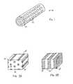
- Tubular body 22can be formed by layering multiple layers or films of the composite material. Referring to FIG. 3 , a method of making stent 20 is shown. Multiple layers 32 of the composite material can be formed according to the techniques described above. As shown, layers 32 have a lamellar structure, but the layers can have any structure of the composite material. In some embodiments, the layers can have different structures. For example, a layer can have a lamellar structure, and another layer can have a hexagonal structure. Layers 32 are then laminated together to form a sheet 34 , e.g., one having a predetermined final thickness.
- an adhesion enhancing materialcan be incorporated into or applied to the composite material.
- An adhesion enhancing materialcan be used, for example, to enhance the adhesion between adjacent layers.
- adhesion enhancing materialsinclude epoxy or anhydride modified polyolefins, such as LOTADER® (Elf Atochem) and KODAR® PETG (Eastman Kodak).
- LOTADER®Elf Atochem
- KODAR® PETGEastman Kodak
- the amount of adhesion enhancing materialcan vary depending upon the intended use.
- the adhesion between one or more adjacent layerscan vary as layer thickness is varied.
- the composite materialcan be used in other medical devices.
- the composite materialcan be included in a medical balloon, e.g., an angioplasty balloon; a filter; or a balloon catheter. Examples of devices suitable for use with MRI are described in U.S. Ser. No. 10/216,988, filed Aug. 12, 2002.
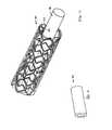
- the composite materialcan be included in a vascular graft 50 ( FIG. 5 ), e.g., described in U.S. Pat. No. 6,428,571.
- Tubular body 22can be used as a medical tubing, e.g., as a catheter body.
Landscapes
- Health & Medical Sciences (AREA)
- Engineering & Computer Science (AREA)
- Biomedical Technology (AREA)
- Heart & Thoracic Surgery (AREA)
- Life Sciences & Earth Sciences (AREA)
- Cardiology (AREA)
- Oral & Maxillofacial Surgery (AREA)
- Transplantation (AREA)
- Physics & Mathematics (AREA)
- Vascular Medicine (AREA)
- Optics & Photonics (AREA)
- Animal Behavior & Ethology (AREA)
- General Health & Medical Sciences (AREA)
- Public Health (AREA)
- Veterinary Medicine (AREA)
- Materials For Medical Uses (AREA)
- Prostheses (AREA)
- Compositions Of Macromolecular Compounds (AREA)
Abstract
Description
Claims (16)
Priority Applications (6)
| Application Number | Priority Date | Filing Date | Title |
|---|---|---|---|
| US10/299,466US8449601B2 (en) | 2002-11-19 | 2002-11-19 | Medical devices |
| PCT/US2003/037281WO2004045464A2 (en) | 2002-11-19 | 2003-11-19 | Medical devices |
| EP03786967.4AEP1562519B1 (en) | 2002-11-19 | 2003-11-19 | Medical devices |
| AU2003295763AAU2003295763A1 (en) | 2002-11-19 | 2003-11-19 | Medical devices |
| CA002506622ACA2506622A1 (en) | 2002-11-19 | 2003-11-19 | Medical devices |
| JP2004554013AJP4819363B2 (en) | 2002-11-19 | 2003-11-19 | Medical device |
Applications Claiming Priority (1)
| Application Number | Priority Date | Filing Date | Title |
|---|---|---|---|
| US10/299,466US8449601B2 (en) | 2002-11-19 | 2002-11-19 | Medical devices |
Publications (2)
| Publication Number | Publication Date |
|---|---|
| US20040098089A1 US20040098089A1 (en) | 2004-05-20 |
| US8449601B2true US8449601B2 (en) | 2013-05-28 |
Family
ID=32297704
Family Applications (1)
| Application Number | Title | Priority Date | Filing Date |
|---|---|---|---|
| US10/299,466Expired - Fee RelatedUS8449601B2 (en) | 2002-11-19 | 2002-11-19 | Medical devices |
Country Status (6)
| Country | Link |
|---|---|
| US (1) | US8449601B2 (en) |
| EP (1) | EP1562519B1 (en) |
| JP (1) | JP4819363B2 (en) |
| AU (1) | AU2003295763A1 (en) |
| CA (1) | CA2506622A1 (en) |
| WO (1) | WO2004045464A2 (en) |
Families Citing this family (65)
| Publication number | Priority date | Publication date | Assignee | Title |
|---|---|---|---|---|
| US7959664B2 (en)* | 1996-12-26 | 2011-06-14 | Medinol, Ltd. | Flat process of drug coating for stents |
| US7713297B2 (en) | 1998-04-11 | 2010-05-11 | Boston Scientific Scimed, Inc. | Drug-releasing stent with ceramic-containing layer |
| WO2003002243A2 (en) | 2001-06-27 | 2003-01-09 | Remon Medical Technologies Ltd. | Method and device for electrochemical formation of therapeutic species in vivo |
| US20050266039A1 (en)* | 2004-05-27 | 2005-12-01 | Jan Weber | Coated medical device and method for making the same |
| JP3857295B2 (en)* | 2004-11-10 | 2006-12-13 | 三菱電機株式会社 | Semiconductor light emitting device |
| US20060105016A1 (en)* | 2004-11-12 | 2006-05-18 | Gray Robert W | Device compatible with magnetic resonance imaging |
| US20070021667A1 (en)* | 2005-05-19 | 2007-01-25 | Biophan Technologies, Inc. | Electromagnetic resonant circuit sleeve for implantable medical device |
| US20060276875A1 (en)* | 2005-05-27 | 2006-12-07 | Stinson Jonathan S | Medical devices |
| US20070112421A1 (en)* | 2005-11-14 | 2007-05-17 | O'brien Barry | Medical device with a grooved surface |
| US8840660B2 (en) | 2006-01-05 | 2014-09-23 | Boston Scientific Scimed, Inc. | Bioerodible endoprostheses and methods of making the same |
| US8089029B2 (en) | 2006-02-01 | 2012-01-03 | Boston Scientific Scimed, Inc. | Bioabsorbable metal medical device and method of manufacture |
| US8828077B2 (en)* | 2006-03-15 | 2014-09-09 | Medinol Ltd. | Flat process of preparing drug eluting stents |
| US20070224235A1 (en) | 2006-03-24 | 2007-09-27 | Barron Tenney | Medical devices having nanoporous coatings for controlled therapeutic agent delivery |
| US8187620B2 (en) | 2006-03-27 | 2012-05-29 | Boston Scientific Scimed, Inc. | Medical devices comprising a porous metal oxide or metal material and a polymer coating for delivering therapeutic agents |
| US8048150B2 (en) | 2006-04-12 | 2011-11-01 | Boston Scientific Scimed, Inc. | Endoprosthesis having a fiber meshwork disposed thereon |
| US8815275B2 (en) | 2006-06-28 | 2014-08-26 | Boston Scientific Scimed, Inc. | Coatings for medical devices comprising a therapeutic agent and a metallic material |
| WO2008002778A2 (en) | 2006-06-29 | 2008-01-03 | Boston Scientific Limited | Medical devices with selective coating |
| EP2054537A2 (en) | 2006-08-02 | 2009-05-06 | Boston Scientific Scimed, Inc. | Endoprosthesis with three-dimensional disintegration control |
| EP2068757B1 (en) | 2006-09-14 | 2011-05-11 | Boston Scientific Limited | Medical devices with drug-eluting coating |
| JP2010503489A (en) | 2006-09-15 | 2010-02-04 | ボストン サイエンティフィック リミテッド | Biodegradable endoprosthesis and method for producing the same |
| ES2357661T3 (en) | 2006-09-15 | 2011-04-28 | Boston Scientific Scimed, Inc. | BIOEROSIONABLE ENDOPROOTHESIS WITH BIOESTABLE INORGANIC LAYERS. |
| EP2959925B1 (en) | 2006-09-15 | 2018-08-29 | Boston Scientific Limited | Medical devices and methods of making the same |
| WO2008034066A1 (en) | 2006-09-15 | 2008-03-20 | Boston Scientific Limited | Bioerodible endoprostheses and methods of making the same |
| WO2008036548A2 (en) | 2006-09-18 | 2008-03-27 | Boston Scientific Limited | Endoprostheses |
| US20080102098A1 (en)* | 2006-10-30 | 2008-05-01 | Vipul Bhupendra Dave | Method for making a device having discrete regions |
| US7981150B2 (en) | 2006-11-09 | 2011-07-19 | Boston Scientific Scimed, Inc. | Endoprosthesis with coatings |
| US20090062910A1 (en)* | 2006-11-16 | 2009-03-05 | Shippy Iii James Lee | Stent with differential timing of abluminal and luminal release of a therapeutic agent |
| ES2506144T3 (en) | 2006-12-28 | 2014-10-13 | Boston Scientific Limited | Bioerodible endoprosthesis and their manufacturing procedure |
| US8070797B2 (en) | 2007-03-01 | 2011-12-06 | Boston Scientific Scimed, Inc. | Medical device with a porous surface for delivery of a therapeutic agent |
| US8431149B2 (en) | 2007-03-01 | 2013-04-30 | Boston Scientific Scimed, Inc. | Coated medical devices for abluminal drug delivery |
| US8067054B2 (en) | 2007-04-05 | 2011-11-29 | Boston Scientific Scimed, Inc. | Stents with ceramic drug reservoir layer and methods of making and using the same |
| US7976915B2 (en) | 2007-05-23 | 2011-07-12 | Boston Scientific Scimed, Inc. | Endoprosthesis with select ceramic morphology |
| US8002823B2 (en) | 2007-07-11 | 2011-08-23 | Boston Scientific Scimed, Inc. | Endoprosthesis coating |
| US7942926B2 (en) | 2007-07-11 | 2011-05-17 | Boston Scientific Scimed, Inc. | Endoprosthesis coating |
| EP2187988B1 (en) | 2007-07-19 | 2013-08-21 | Boston Scientific Limited | Endoprosthesis having a non-fouling surface |
| US7931683B2 (en) | 2007-07-27 | 2011-04-26 | Boston Scientific Scimed, Inc. | Articles having ceramic coated surfaces |
| US8815273B2 (en) | 2007-07-27 | 2014-08-26 | Boston Scientific Scimed, Inc. | Drug eluting medical devices having porous layers |
| WO2009018340A2 (en) | 2007-07-31 | 2009-02-05 | Boston Scientific Scimed, Inc. | Medical device coating by laser cladding |
| JP2010535541A (en) | 2007-08-03 | 2010-11-25 | ボストン サイエンティフィック リミテッド | Coating for medical devices with large surface area |
| US8052745B2 (en) | 2007-09-13 | 2011-11-08 | Boston Scientific Scimed, Inc. | Endoprosthesis |
| US20090076591A1 (en)* | 2007-09-19 | 2009-03-19 | Boston Scientific Scimed, Inc. | Stent Design Allowing Extended Release of Drug and/or Enhanced Adhesion of Polymer to OD Surface |
| US7938855B2 (en) | 2007-11-02 | 2011-05-10 | Boston Scientific Scimed, Inc. | Deformable underlayer for stent |
| US20090118813A1 (en)* | 2007-11-02 | 2009-05-07 | Torsten Scheuermann | Nano-patterned implant surfaces |
| US8216632B2 (en) | 2007-11-02 | 2012-07-10 | Boston Scientific Scimed, Inc. | Endoprosthesis coating |
| US8029554B2 (en) | 2007-11-02 | 2011-10-04 | Boston Scientific Scimed, Inc. | Stent with embedded material |
| US7833266B2 (en) | 2007-11-28 | 2010-11-16 | Boston Scientific Scimed, Inc. | Bifurcated stent with drug wells for specific ostial, carina, and side branch treatment |
| US8920491B2 (en) | 2008-04-22 | 2014-12-30 | Boston Scientific Scimed, Inc. | Medical devices having a coating of inorganic material |
| US8932346B2 (en) | 2008-04-24 | 2015-01-13 | Boston Scientific Scimed, Inc. | Medical devices having inorganic particle layers |
| US7998192B2 (en) | 2008-05-09 | 2011-08-16 | Boston Scientific Scimed, Inc. | Endoprostheses |
| US8236046B2 (en) | 2008-06-10 | 2012-08-07 | Boston Scientific Scimed, Inc. | Bioerodible endoprosthesis |
| EP2303350A2 (en) | 2008-06-18 | 2011-04-06 | Boston Scientific Scimed, Inc. | Endoprosthesis coating |
| US7951193B2 (en)* | 2008-07-23 | 2011-05-31 | Boston Scientific Scimed, Inc. | Drug-eluting stent |
| US7985252B2 (en) | 2008-07-30 | 2011-07-26 | Boston Scientific Scimed, Inc. | Bioerodible endoprosthesis |
| US8076529B2 (en) | 2008-09-26 | 2011-12-13 | Abbott Cardiovascular Systems, Inc. | Expandable member formed of a fibrous matrix for intraluminal drug delivery |
| US8226603B2 (en) | 2008-09-25 | 2012-07-24 | Abbott Cardiovascular Systems Inc. | Expandable member having a covering formed of a fibrous matrix for intraluminal drug delivery |
| US8049061B2 (en) | 2008-09-25 | 2011-11-01 | Abbott Cardiovascular Systems, Inc. | Expandable member formed of a fibrous matrix having hydrogel polymer for intraluminal drug delivery |
| US8382824B2 (en) | 2008-10-03 | 2013-02-26 | Boston Scientific Scimed, Inc. | Medical implant having NANO-crystal grains with barrier layers of metal nitrides or fluorides |
| US8231980B2 (en) | 2008-12-03 | 2012-07-31 | Boston Scientific Scimed, Inc. | Medical implants including iridium oxide |
| EP2403546A2 (en) | 2009-03-02 | 2012-01-11 | Boston Scientific Scimed, Inc. | Self-buffering medical implants |
| US8071156B2 (en) | 2009-03-04 | 2011-12-06 | Boston Scientific Scimed, Inc. | Endoprostheses |
| US8287937B2 (en) | 2009-04-24 | 2012-10-16 | Boston Scientific Scimed, Inc. | Endoprosthese |
| EP2544623B1 (en)* | 2010-03-09 | 2018-01-10 | Solinas Medical Inc. | Self-closing devices |
| WO2011119536A1 (en) | 2010-03-22 | 2011-09-29 | Abbott Cardiovascular Systems Inc. | Stent delivery system having a fibrous matrix covering with improved stent retention |
| US8668732B2 (en) | 2010-03-23 | 2014-03-11 | Boston Scientific Scimed, Inc. | Surface treated bioerodible metal endoprostheses |
| ES2973834T3 (en) | 2013-04-13 | 2024-06-24 | Solinas Medical Inc | Automatic closing devices, and apparatus and methods for manufacturing and supplying the same |
Citations (15)
| Publication number | Priority date | Publication date | Assignee | Title |
|---|---|---|---|---|
| DE2152142A1 (en) | 1970-11-20 | 1972-05-25 | Vyzk Ustav Pletarzskiy | Incompressible folded vascular prosthesis |
| US5195969A (en) | 1991-04-26 | 1993-03-23 | Boston Scientific Corporation | Co-extruded medical balloons and catheter using such balloons |
| US5270086A (en) | 1989-09-25 | 1993-12-14 | Schneider (Usa) Inc. | Multilayer extrusion of angioplasty balloons |
| US5366504A (en) | 1992-05-20 | 1994-11-22 | Boston Scientific Corporation | Tubular medical prosthesis |
| EP0756853A1 (en)* | 1995-08-01 | 1997-02-05 | Advanced Cardiovascular Systems, Inc. | Composite metal and polymer locking stents for drug delivery |
| US5674242A (en) | 1995-06-06 | 1997-10-07 | Quanam Medical Corporation | Endoprosthetic device with therapeutic compound |
| US5693085A (en)* | 1994-04-29 | 1997-12-02 | Scimed Life Systems, Inc. | Stent with collagen |
| US5780807A (en) | 1994-11-28 | 1998-07-14 | Advanced Cardiovascular Systems, Inc. | Method and apparatus for direct laser cutting of metal stents |
| US5824037A (en)* | 1995-10-03 | 1998-10-20 | Medtronic, Inc. | Modular intraluminal prostheses construction and methods |
| WO1999032051A1 (en) | 1997-12-22 | 1999-07-01 | Impra, Inc. | Supported graft and methods of making same |
| US6428571B1 (en) | 1996-01-22 | 2002-08-06 | Scimed Life Systems, Inc. | Self-sealing PTFE vascular graft and manufacturing methods |
| WO2002083194A1 (en) | 2001-04-12 | 2002-10-24 | Therics, Inc. | Method and apparatus for engineered regenerative biostructures |
| WO2002083223A1 (en) | 2001-04-17 | 2002-10-24 | Salviac Limited | A catheter |
| US20030004563A1 (en)* | 2001-06-29 | 2003-01-02 | Jackson Gregg A. | Polymeric stent suitable for imaging by MRI and fluoroscopy |
| US6645626B2 (en)* | 2001-04-13 | 2003-11-11 | Cornell Research Foundation, Inc. | Superparamagnetic nanostructured materials |
Family Cites Families (5)
| Publication number | Priority date | Publication date | Assignee | Title |
|---|---|---|---|---|
| US5343729A (en)* | 1985-03-15 | 1994-09-06 | Weirton Steel Corporation | Fabricating one-piece can bodies with controlled side wall elongation |
| US5216043A (en)* | 1991-12-12 | 1993-06-01 | Minnesota Mining And Manufacturing Company | Degradable thermophastic compositions and blends with naturally biodegradable polymers |
| JP3507503B2 (en)* | 1995-03-10 | 2004-03-15 | インプラ・インコーポレーテッド | Sealable stent for body cavity, method for producing the same, and method for introducing the same into body cavity |
| JPH09183819A (en)* | 1995-12-28 | 1997-07-15 | Nippon Oil & Fats Co Ltd | Copolymer having phospholipid-like structure and medical material |
| US5962007A (en)* | 1997-12-19 | 1999-10-05 | Indigo Medical, Inc. | Use of a multi-component coil medical construct |
- 2002
- 2002-11-19USUS10/299,466patent/US8449601B2/ennot_activeExpired - Fee Related
- 2003
- 2003-11-19EPEP03786967.4Apatent/EP1562519B1/ennot_activeExpired - Lifetime
- 2003-11-19CACA002506622Apatent/CA2506622A1/ennot_activeAbandoned
- 2003-11-19JPJP2004554013Apatent/JP4819363B2/ennot_activeExpired - Fee Related
- 2003-11-19AUAU2003295763Apatent/AU2003295763A1/ennot_activeAbandoned
- 2003-11-19WOPCT/US2003/037281patent/WO2004045464A2/enactiveApplication Filing
Patent Citations (15)
| Publication number | Priority date | Publication date | Assignee | Title |
|---|---|---|---|---|
| DE2152142A1 (en) | 1970-11-20 | 1972-05-25 | Vyzk Ustav Pletarzskiy | Incompressible folded vascular prosthesis |
| US5270086A (en) | 1989-09-25 | 1993-12-14 | Schneider (Usa) Inc. | Multilayer extrusion of angioplasty balloons |
| US5195969A (en) | 1991-04-26 | 1993-03-23 | Boston Scientific Corporation | Co-extruded medical balloons and catheter using such balloons |
| US5366504A (en) | 1992-05-20 | 1994-11-22 | Boston Scientific Corporation | Tubular medical prosthesis |
| US5693085A (en)* | 1994-04-29 | 1997-12-02 | Scimed Life Systems, Inc. | Stent with collagen |
| US5780807A (en) | 1994-11-28 | 1998-07-14 | Advanced Cardiovascular Systems, Inc. | Method and apparatus for direct laser cutting of metal stents |
| US5674242A (en) | 1995-06-06 | 1997-10-07 | Quanam Medical Corporation | Endoprosthetic device with therapeutic compound |
| EP0756853A1 (en)* | 1995-08-01 | 1997-02-05 | Advanced Cardiovascular Systems, Inc. | Composite metal and polymer locking stents for drug delivery |
| US5824037A (en)* | 1995-10-03 | 1998-10-20 | Medtronic, Inc. | Modular intraluminal prostheses construction and methods |
| US6428571B1 (en) | 1996-01-22 | 2002-08-06 | Scimed Life Systems, Inc. | Self-sealing PTFE vascular graft and manufacturing methods |
| WO1999032051A1 (en) | 1997-12-22 | 1999-07-01 | Impra, Inc. | Supported graft and methods of making same |
| WO2002083194A1 (en) | 2001-04-12 | 2002-10-24 | Therics, Inc. | Method and apparatus for engineered regenerative biostructures |
| US6645626B2 (en)* | 2001-04-13 | 2003-11-11 | Cornell Research Foundation, Inc. | Superparamagnetic nanostructured materials |
| WO2002083223A1 (en) | 2001-04-17 | 2002-10-24 | Salviac Limited | A catheter |
| US20030004563A1 (en)* | 2001-06-29 | 2003-01-02 | Jackson Gregg A. | Polymeric stent suitable for imaging by MRI and fluoroscopy |
Non-Patent Citations (9)
| Title |
|---|
| Craig, Charles H., et al., U.S. Appl. No. 10/112,391, "Platinum Enhanced Alloy and Intravascular or Implantable Medical Devices Manufactured Therefrom" filed Mar. 28, 2002. |
| International Search Report mailed May 28, 2004. |
| Mendes, M.; Oliveria, V.; Vilar, R.; Beinhorn, F.; Ihlemann, J.; Conde, O.; "Femtosecond Ultraviolet Laser Micromachining of A1203-TiC ceramics", Journal of Laser Applications, vol. II, No. 5, pp. 211-215, Oct. 1999. |
| Stinson, Jonathan, U.S. Appl. No. 10/229,548, "Medical Devices and Methods of Making the Same" filed Aug. 8, 2002. |
| Templin, M. et al. "Organically Modified Alununosilicate Mesostructures from Block Copolymer Phases", Science, vol. 278, 1795-1798, Dec. 5, 1997.* |
| Templin, M.; Franck, A.; Du Chesne, A.; Leist, H.; Zhang, Y.; Ulrich, R.; Schädler, V.; Wiesner, U.; "Organically Modified Aluminosilicate Mesostructures from Block Copolymer Phases", Science, vol. 278, pp. 1795-1798, Dec. 5, 1997. |
| Weber, Jan, U.S. Appl. No. 09/724,503, "Method for Manufacturing a Medical Device Having a Coated Portion by Laser Ablation", filed Nov. 28, 2000. |
| Weber, Jan, U.S. Appl. No. 10/216,988, "Tunable MRI Enhancing Device", filed Aug. 12. 2002. |
| Zhong, Sheng-Ping, et al., U.S. Appl. No. 09/895,415, "Coating a Medical Appliance With a Bubble Jet Printing Head", filed Jul. 2, 2001. |
Also Published As
| Publication number | Publication date |
|---|---|
| WO2004045464A3 (en) | 2004-07-29 |
| EP1562519B1 (en) | 2016-03-09 |
| WO2004045464A2 (en) | 2004-06-03 |
| AU2003295763A1 (en) | 2004-06-15 |
| JP2006506198A (en) | 2006-02-23 |
| CA2506622A1 (en) | 2004-06-03 |
| JP4819363B2 (en) | 2011-11-24 |
| EP1562519A2 (en) | 2005-08-17 |
| US20040098089A1 (en) | 2004-05-20 |
Similar Documents
| Publication | Publication Date | Title |
|---|---|---|
| US8449601B2 (en) | Medical devices | |
| US12156824B2 (en) | Lattice | |
| US5984963A (en) | Endovascular stents | |
| CN103313681B (en) | bracket | |
| US9682178B2 (en) | Implantable medical devices fabricated from polymers with radiopaque groups | |
| EP1747030B1 (en) | Medical devices and methods of making the same | |
| EP1550477A1 (en) | Stent and process for producing the same | |
| ES2695527T3 (en) | Recovered thin-film composite endovascular devices | |
| US8679572B2 (en) | Coated stent | |
| JPH09501583A (en) | Tubular endoluminal implant | |
| JP2003520628A (en) | Tubular stent-graft synthesis device and method of manufacture | |
| EP2034927B1 (en) | Medical devices including composites | |
| US20250057673A1 (en) | Lattice | |
| AU2017203267B2 (en) | Endoprosthesis | |
| US20170333604A1 (en) | Ready-made biomedical devices for in vivo welding | |
| JP2000503874A (en) | Radially supported polytetrafluoroethylene vascular graft |
Legal Events
| Date | Code | Title | Description |
|---|---|---|---|
| AS | Assignment | Owner name:SCIMED LIFE SYSTEMS, INC., MINNESOTA Free format text:ASSIGNMENT OF ASSIGNORS INTEREST;ASSIGNOR:WEBER, JAN;REEL/FRAME:013511/0928 Effective date:20021114 | |
| AS | Assignment | Owner name:BOSTON SCIENTIFIC SCIMED, INC., MINNESOTA Free format text:CHANGE OF NAME;ASSIGNOR:SCIMED LIFE SYSTEMS, INC.;REEL/FRAME:018505/0868 Effective date:20050101 Owner name:BOSTON SCIENTIFIC SCIMED, INC.,MINNESOTA Free format text:CHANGE OF NAME;ASSIGNOR:SCIMED LIFE SYSTEMS, INC.;REEL/FRAME:018505/0868 Effective date:20050101 | |
| STCF | Information on status: patent grant | Free format text:PATENTED CASE | |
| CC | Certificate of correction | ||
| CC | Certificate of correction | ||
| FPAY | Fee payment | Year of fee payment:4 | |
| FEPP | Fee payment procedure | Free format text:MAINTENANCE FEE REMINDER MAILED (ORIGINAL EVENT CODE: REM.); ENTITY STATUS OF PATENT OWNER: LARGE ENTITY | |
| LAPS | Lapse for failure to pay maintenance fees | Free format text:PATENT EXPIRED FOR FAILURE TO PAY MAINTENANCE FEES (ORIGINAL EVENT CODE: EXP.); ENTITY STATUS OF PATENT OWNER: LARGE ENTITY | |
| STCH | Information on status: patent discontinuation | Free format text:PATENT EXPIRED DUE TO NONPAYMENT OF MAINTENANCE FEES UNDER 37 CFR 1.362 | |
| FP | Lapsed due to failure to pay maintenance fee | Effective date:20210528 |