US8449543B2 - Bone growth device and method - Google Patents
Bone growth device and methodDownload PDFInfo
- Publication number
- US8449543B2 US8449543B2US12/875,585US87558510AUS8449543B2US 8449543 B2US8449543 B2US 8449543B2US 87558510 AUS87558510 AUS 87558510AUS 8449543 B2US8449543 B2US 8449543B2
- Authority
- US
- United States
- Prior art keywords
- housing
- bone
- permanent magnet
- planetary gear
- distraction
- Prior art date
- Legal status (The legal status is an assumption and is not a legal conclusion. Google has not performed a legal analysis and makes no representation as to the accuracy of the status listed.)
- Active, expires
Links
Images


Classifications
- A—HUMAN NECESSITIES
- A61—MEDICAL OR VETERINARY SCIENCE; HYGIENE
- A61B—DIAGNOSIS; SURGERY; IDENTIFICATION
- A61B17/00—Surgical instruments, devices or methods
- A61B17/56—Surgical instruments or methods for treatment of bones or joints; Devices specially adapted therefor
- A61B17/58—Surgical instruments or methods for treatment of bones or joints; Devices specially adapted therefor for osteosynthesis, e.g. bone plates, screws or setting implements
- A61B17/68—Internal fixation devices, including fasteners and spinal fixators, even if a part thereof projects from the skin
- A61B17/72—Intramedullary devices, e.g. pins or nails
- A61B17/7216—Intramedullary devices, e.g. pins or nails for bone lengthening or compression
- A—HUMAN NECESSITIES
- A61—MEDICAL OR VETERINARY SCIENCE; HYGIENE
- A61B—DIAGNOSIS; SURGERY; IDENTIFICATION
- A61B17/00—Surgical instruments, devices or methods
- A61B17/16—Instruments for performing osteoclasis; Drills or chisels for bones; Trepans
- A61B17/17—Guides or aligning means for drills, mills, pins or wires
- A61B17/1725—Guides or aligning means for drills, mills, pins or wires for applying transverse screws or pins through intramedullary nails or pins
- A—HUMAN NECESSITIES
- A61—MEDICAL OR VETERINARY SCIENCE; HYGIENE
- A61B—DIAGNOSIS; SURGERY; IDENTIFICATION
- A61B17/00—Surgical instruments, devices or methods
- A61B17/56—Surgical instruments or methods for treatment of bones or joints; Devices specially adapted therefor
- A61B17/58—Surgical instruments or methods for treatment of bones or joints; Devices specially adapted therefor for osteosynthesis, e.g. bone plates, screws or setting implements
- A61B17/60—Surgical instruments or methods for treatment of bones or joints; Devices specially adapted therefor for osteosynthesis, e.g. bone plates, screws or setting implements for external osteosynthesis, e.g. distractors, contractors
- A61B17/66—Alignment, compression or distraction mechanisms
- A—HUMAN NECESSITIES
- A61—MEDICAL OR VETERINARY SCIENCE; HYGIENE
- A61B—DIAGNOSIS; SURGERY; IDENTIFICATION
- A61B17/00—Surgical instruments, devices or methods
- A61B17/56—Surgical instruments or methods for treatment of bones or joints; Devices specially adapted therefor
- A61B17/58—Surgical instruments or methods for treatment of bones or joints; Devices specially adapted therefor for osteosynthesis, e.g. bone plates, screws or setting implements
- A61B17/68—Internal fixation devices, including fasteners and spinal fixators, even if a part thereof projects from the skin
- A61B17/72—Intramedullary devices, e.g. pins or nails
- A61B17/7233—Intramedullary devices, e.g. pins or nails with special means of locking the nail to the bone
- A61B17/7258—Intramedullary devices, e.g. pins or nails with special means of locking the nail to the bone with laterally expanding parts, e.g. for gripping the bone
- A—HUMAN NECESSITIES
- A61—MEDICAL OR VETERINARY SCIENCE; HYGIENE
- A61B—DIAGNOSIS; SURGERY; IDENTIFICATION
- A61B17/00—Surgical instruments, devices or methods
- A61B17/56—Surgical instruments or methods for treatment of bones or joints; Devices specially adapted therefor
- A61B17/58—Surgical instruments or methods for treatment of bones or joints; Devices specially adapted therefor for osteosynthesis, e.g. bone plates, screws or setting implements
- A61B17/88—Osteosynthesis instruments; Methods or means for implanting or extracting internal or external fixation devices
- A61B17/8866—Osteosynthesis instruments; Methods or means for implanting or extracting internal or external fixation devices for gripping or pushing bones, e.g. approximators
- A—HUMAN NECESSITIES
- A61—MEDICAL OR VETERINARY SCIENCE; HYGIENE
- A61B—DIAGNOSIS; SURGERY; IDENTIFICATION
- A61B17/00—Surgical instruments, devices or methods
- A61B17/56—Surgical instruments or methods for treatment of bones or joints; Devices specially adapted therefor
- A61B17/58—Surgical instruments or methods for treatment of bones or joints; Devices specially adapted therefor for osteosynthesis, e.g. bone plates, screws or setting implements
- A61B17/88—Osteosynthesis instruments; Methods or means for implanting or extracting internal or external fixation devices
- A61B17/8875—Screwdrivers, spanners or wrenches
- A61B17/8886—Screwdrivers, spanners or wrenches holding the screw head
- A61B17/8888—Screwdrivers, spanners or wrenches holding the screw head at its central region
- A—HUMAN NECESSITIES
- A61—MEDICAL OR VETERINARY SCIENCE; HYGIENE
- A61B—DIAGNOSIS; SURGERY; IDENTIFICATION
- A61B17/00—Surgical instruments, devices or methods
- A61B17/56—Surgical instruments or methods for treatment of bones or joints; Devices specially adapted therefor
- A61B17/58—Surgical instruments or methods for treatment of bones or joints; Devices specially adapted therefor for osteosynthesis, e.g. bone plates, screws or setting implements
- A61B17/68—Internal fixation devices, including fasteners and spinal fixators, even if a part thereof projects from the skin
- A61B2017/681—Alignment, compression, or distraction mechanisms
- A—HUMAN NECESSITIES
- A61—MEDICAL OR VETERINARY SCIENCE; HYGIENE
- A61L—METHODS OR APPARATUS FOR STERILISING MATERIALS OR OBJECTS IN GENERAL; DISINFECTION, STERILISATION OR DEODORISATION OF AIR; CHEMICAL ASPECTS OF BANDAGES, DRESSINGS, ABSORBENT PADS OR SURGICAL ARTICLES; MATERIALS FOR BANDAGES, DRESSINGS, ABSORBENT PADS OR SURGICAL ARTICLES
- A61L2430/00—Materials or treatment for tissue regeneration
- A61L2430/02—Materials or treatment for tissue regeneration for reconstruction of bones; weight-bearing implants
Definitions
- the field of the inventiongenerally relates to medical devices for treating conditions involving the skeletal system and in particular bone growth applications.
- Distraction osteogenesisalso known as distraction callotasis and osteodistraction has been used successfully to lengthen long bones of the body.
- the boneif not already fractured, is purposely fractured by means of a corticotomy, and the two segments of bone are gradually distracted apart, which allows new bone to form in the gap. If the distraction rate is too high, there is a risk of nonunion, if the rate is too low, there is a risk that the two segments will completely fuse to each other before the distraction period is complete. When the desired length of the bone is achieved using this process, the bone is allowed to consolidate.
- Distraction osteogenesis applicationsare mainly focused on the growth of the femur or tibia, but may also include the humerus, the jaw bone (micrognathia), or other bones.
- the reasons for lengthening or growing bonesare multifold, the applications including, but not limited to: post osteosarcoma bone cancer; cosmetic lengthening (both legs-femur and/or tibia) in short stature or dwarfism/achondroplasia; lengthening of one limb to match the other (congenital, post-trauma, post-skeletal disorder, prosthetic knee joint), non-unions.
- intramedullary distraction nailshave been surgically implanted which are contained entirely within the bone. Some are automatically lengthened via repeated rotation of the patient's limb. This can sometimes be painful to the patient, and can often proceed in an uncontrolled fashion. This therefore makes it difficult to follow the strict daily or weekly lengthening regime that avoids nonunion (if too fast) or early consolidation (if too slow). Lower limb distraction rates are on the order of one millimeter per day.
- Other intramedullary nailshave been developed which have an implanted motor and are remotely controlled. The motorized intramedullary nails have an antenna which needs to be implanted subcutaneously, thus complicating the surgical procedure, and making it more invasive.
- a lengthening deviceis configured for placement inside or across bone having first and second separate sections.
- the deviceincludes a housing configured for attachment to one of the first and second separate bone sections and a distraction shaft having an internal cavity along a length thereof and configured for attachment to the other of the first and second separate bone sections.
- the deviceincludes a permanent magnet configured for rotation relative to the housing and having at least two poles, the permanent magnet operatively coupled to a lead screw, the lead screw interfacing with a threaded portion of the internal cavity of the distraction shaft.
- a thrust bearingis disposed in the housing and interposed between the lead screw and the permanent magnet, the thrust bearing sandwiched between first and second abutments in the housing.
- a lengthening deviceis configured for placement inside an intramedullary canal of a bone having first and second separate sections.
- the deviceincludes a housing configured for attachment to one of the first and second separate bone sections and a distraction shaft having an internal cavity along a length thereof and configured for attachment to the other of the first and second separate bone sections.
- a permanent magnetis disposed in the housing and configured for rotation and having at least two poles.
- a planetary gear set having a plurality of gearsis provided, wherein one of the gears is operatively coupled to the permanent magnet and configured for transmitting torque, and wherein another gear of the plurality of gears terminates in an output shaft operatively coupled to a lead screw, the lead screw interfacing with a threaded portion of the internal cavity of the distraction shaft.
- a lengthening systemis configured for placement inside an intramedullary canal of a bone.
- the systemincludes an actuator with a housing containing a rotatable permanent magnet and moveable distraction shaft telescopically mounted relative the housing, the moveable distraction shaft operatively coupled to the rotatable permanent magnet via a lead screw, wherein a distal end of the distraction shaft is configured for attachment to a first region of the bone and wherein a proximal end of the actuator has a geometrically shaped hub of a male type.
- the systemfurther includes an extension rod having at one end thereof a geometrically shaped hub of a female type configured to secure to the geometrically shaped hub of the male type disposed on the actuator, wherein an opposing end of the extension rod is configured for attachment to a second region of the bone.
- a lengthening systemis configured for placement inside an intramedullary canal of a bone.
- the systemincludes an actuator with a housing containing a rotatable permanent magnet and a moveable distraction shaft telescopically mounted relative the housing, the moveable distraction shaft operatively coupled to the rotatable permanent magnet via a lead screw, wherein a distal end of the distraction shaft is configured for attachment to a first region of the bone and wherein a proximal end of the actuator comprises a geometrically shaped hub of a female type.
- the systemfurther includes an extension rod having at one end thereof a geometrically shaped hub of a male type configured to secure to the geometrically shaped hub of the female type disposed on the actuator, wherein an opposing end of the extension rod is configured for attachment to a second region of the bone.
- an external adjustment device for adjusting an adjustable implantincludes a power supply, a control module, and a handheld device comprising at least one permanent magnet.
- the handheld deviceis configured to be placed on a first side of a patient's limb and the at least one permanent magnet is configured to turn a cylindrical magnet located inside an adjustable implant.
- the control moduleis configured to restrict the number of turns of the cylindrical magnet located inside the adjustable implant.
- FIG. 1illustrates side view of an intramedullary lengthening device in place within a bone according to one embodiment.
- FIG. 2illustrates a side view of the intramedullary lengthening device of FIG. 1 .
- FIG. 3Aillustrates a cross-sectional view of the intramedullary lengthening device of FIGS. 1 and 2 taken along the line 3 A- 3 A of FIG. 2 .
- FIG. 3Billustrates a detailed view of the intramedullary lengthening device of FIG. 3A from the area of circle 3 B.
- FIG. 3Cillustrates a cross-sectional view of the intramedullary lengthening device of FIGS. 1 and 2 taken along the line 3 C in FIG. 2 .
- FIG. 4Aillustrates a view of several of the internal components of the intramedullary lengthening device of the prior FIGS.
- FIG. 4Billustrates a lip seal configured for use in the intramedullary lengthening device of the prior FIGS.
- FIG. 5illustrates a detailed view of several internal components of the drive mechanism of the intramedullary lengthening device of the prior figures.
- FIG. 6illustrates a perspective view of an external adjustment device.
- FIG. 7illustrates an exploded view of the magnetic handpiece of the external adjustment device of FIG. 6 .
- FIG. 8illustrates a cross-sectional representation of a prior art electromagnetic external device being positioned around a patient's lower thigh.
- FIG. 9illustrates a cross-sectional representation of the external adjustment device handpiece of FIGS. 6 and 7 being positioned on a patient's lower thigh.
- FIG. 10illustrates a sterilizable kit for use with a modular intramedullary lengthening device.
- FIG. 11illustrates a modular intramedullary lengthening device according to one embodiment.
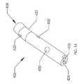
- FIG. 12illustrates one end of the actuator of the intramedullary lengthening device of FIG. 11 .
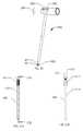
- FIG. 13illustrates an extension rod of the modular intramedullary lengthening device.
- FIG. 14illustrates a second view of the extension rod of FIG. 13 .
- FIG. 15illustrates a proximal drill guide for insertion and attachment of the modular intramedullary lengthening device.
- FIG. 16illustrates a removal tool for removal of the modular intramedullary lengthening device.
- FIG. 17illustrates a torque limiting driver for attaching the extension rod to the actuator of the modular intramedullary device.
- FIG. 18illustrates a section of the actuator of the modular intramedullary lengthening device.
- FIG. 19illustrates a gap (G) between a magnetic handpiece and an intramedullary lengthening device.
- FIG. 20illustrates a locking screw driver for use with the intramedullary lengthening device.
- FIG. 21Aillustrates a locking screw for use with the intramedullary lengthening device.
- FIG. 21Billustrates the locking screw of FIG. 21A taken along line 21 B- 21 B of FIG. 21A .
- FIG. 1illustrates the side view of an intramedullary lengthening device 110 which has been placed through a hole or bore 108 contained within a bone 100 .
- the hole or bore 108may be made by drilling, reaming and the like and may extend through both cortical bone (at the end) and through cancellous (spongy) bone.
- the intramedullary lengthening device 110 illustrated in FIG. 1includes a housing 112 and a distraction shaft 114 .
- the bone 100In order to grow or lengthen the bone 100 , the bone 100 either has a pre-existing separation 106 or is purposely cut or broken to create this separation 106 , dividing the bone into a first section 102 and a second section 104 .
- the cutmay be done prior to inserting and securing the intramedullary lengthening device 110 , or may be done after the device 110 is inserted, for example by use of a flexible Gigli saw.
- the distraction shaft 114 of the intramedullary lengthening device 110is attached to the first section 102 using one or more attachment screws 118 .
- Fasteners other than screws 118 known to those skilled in the artmay also be used to secure the distraction shaft 114 to the first section 102 of the bone 100 .
- the housing 112 of the intramedullary lengthening device 110is secured to the second section 104 of bone 100 using one or more attachment screws 116 . Again, fasteners other than screws 116 may be used to secure the housing 112 to the second section 104 of bone 100 .
- Continually distractedis meant to indicate that distraction occurs on a regular basis which may be on the order of every day or every few days.
- An exemplary distraction rateis one millimeter per day although other distraction rates may be employed. That is to say, a typical distraction regimen may include a daily increase in the length of the intramedullary lengthening device 110 by about one millimeter. This may be done, for example, by four lengthening periods per day, each having 0.25 mm of lengthening.
- the intramedullary lengthening device 110has a magnetic drive system, which allows the distraction shaft 114 to be telescopically extended from the housing 112 , thus forcing the first section 102 and the second section 104 of the bone 100 apart from one another. As the distraction is performed, a portion of the housing 112 is able to slide within the hole or bore 108 of the first section 102 if bone 100 within a displacement section 120 .
- the orientation of the intramedullary lengthening device 110 within the bonemay be opposite of that shown in FIG. 1 .
- the distraction shaft 114may be coupled to the second section 104 of the bone 100 and the housing 112 may be coupled to the first section 102 of the bone 100 .
- the intramedullary lengthening device 110may be placed retrograde, from a hole or bore starting at the distal end of the bone 100 .
- the intramedullary lengthening device 110has one or more distraction shaft screw holes 122 in the distraction shaft 114 through which the screws 118 ( FIG. 1 ) may be placed.
- the housing 112is attached to an end cap 130 which has one or more housing screw holes 124 through which the screws 116 ( FIG. 1 ) may be placed.
- the housing 112 of the intramedullary lengthening device 110includes a magnet housing 128 and a splined housing 126 . These housings 126 , 128 may be attached to each other by means of welding, adhesive bonding or other joining techniques.
- the magnet housing 128is sealably closed at one end (the end opposite the interface with the splined housing 126 ) by the attachment of the end cap 130 .
- the end cap 130may be attached to the magnet housing 128 by means of welding, adhesive bonding or other joining techniques.
- the distraction shaft 114is driven from the housing 112 by means of a lead screw 136 which turns inside a nut 140 that is secured to an inner surface adjacent to a cavity 137 of the distraction shaft 114 .
- the lead screw 136is mechanically coupled, in an indirect manner, to cylindrical permanent magnet 134 contained within the magnet housing 128 .
- rotation of the cylindrical permanent magnet 134which is magnetically driven by an external adjustment device 180 ( FIG. 6 ), effectuates rotation of the lead screw 136 .
- Cylindrical magnet 134is fixedly contained within a magnet casing 158 using, for example, an adhesive such as an epoxy.
- the magnet casing 158rotates relative to the magnet housing 128 .
- the cylindrical magnet 134may be a rare earth magnet such as Nd—Fe—B and may be coated with Parylene or other protective coatings in addition to being protected within the magnet casing 158 , for example hermetically potted with epoxy.
- the magnet casing 158contains an axle 160 on one end which attaches to the interior of a radial bearing 132 .
- the outer diameter of the radial bearing 132is secured to the interior of the end cap 130 . This arrangement allows the cylindrical magnet 134 to rotate with minimal torsional resistance.
- the magnet housing 158includes an axle 161 , which is attached to a first planetary gear set 154 .
- the axle 161includes the sun gear of the first planetary gear set 154 , the sun gear turning the planetary gears of the first planetary gear set 154 .
- the first planetary gear set 154serves to reduce the rotational speed and increase the resultant torque delivery from the cylindrical magnet 134 to the lead screw 136 .
- a second planetary gear set 156is also shown between the first planetary gear set 154 and the lead screw 136 , for further speed reduction and torque augmentation.
- the number of planetary gear sets and/or the number of teeth in the gearsmay be adjusted, in order to achieve the desired speed and torque delivery.
- a lead screw with eighty (80) threads per inch attached to two planetary gear sets of 4:1 gear ratio each inside a 9 mm device with magnet location in the distal femurcan achieve at least 100 lb. of distraction force at a greater than average distance or gap from the external device ( FIG. 9 or FIG. 19 ).
- the planetary gear sets 154 , 156output to a planetary gear output shaft 144 .
- the planetary gear output shaft 144extends through a thrust bearing 138 and is secured (by welding and the like) to a lead screw coupling cap 146 .
- the lead screw 136is secured to the lead screw coupling cap 146 by a locking pin 142 , which extends through a hole in the lead screw 136 and holes in the lead screw coupling cap 146 .
- a locking pin retainer 148is a cylinder that surrounds the locking pin 142 , holding this assembly together. Attaching the lead screw 136 to the rest of the magnet/gear assembly in this manner, assures that the design is not over-constrained, and thus that the lead screw 136 does not gall with the nut 140 .
- a biocompatible greasefor example KRYTOX, may be used on the moving parts (lead screw, nut, bearings, housing, and distraction shaft) in order to minimize frictional losses.
- the lead screw 136is able to freely rotate within a cavity 137 of the distraction shaft 114 , and only need engage with the short length of the nut 140 , this feature also minimizing frictional losses.
- the thrust bearing 138serves to protect the magnet/gear assembly of the drive from any significant compressive or tensile stresses.
- the thrust bearing 138consists of two separate races with ball bearings between the two races. When there is a compressive force on the device, for example, when distracting a bone 100 , and thus resisting the tensile strength of the soft tissues, the thrust bearing 138 abuts against a magnet housing abutment or lip 150 located in the magnet housing 128 . Additionally, though the device is not typically intended for pulling bones together, there may be some applications where this is desired. For example, in certain compressive nail applications it is the goal to hold two fractured sections of a bone together.
- the bone 100may have fractured in a non-uniform or shattered pattern, it may be difficult to determine the desired length of the nail until after it is implanted and fully attached. In these situations, it can be easy to misjudge the length, and so a gap may exist between the bones.
- the device 110By placing a slightly extended intramedullary device 110 and securing it, the device 110 may be retracted magnetically, after it has been secured within the bone fragments, so that it applies the desired compression between the two fragments. In these compressive nail applications, there would be tensile force on the device 110 and the thrust bearing 138 would abut against a splined housing abutment or lip 152 .
- the thrust bearing 138 and a rigid portion of one of the housing sectionstake the large stresses, not the magnet/gear assembly of the drive system.
- the thrust bearing 138is sandwiched between the abutment or lip 150 and the abutment or lip 152 .
- Distraction shaft 114contains several axial grooves 166 .
- the grooves 166have semi-circular indentation cross-sections which allow several balls 164 to roll within them.
- the balls 164are trapped within a linear ball cage 162 .
- the splined housing 126which fits over the balls 164 and linear ball cage 162 has axial grooves 163 ( FIG.
- a lip seal flange 168contains a custom cross-section lip seal 169 (shown in FIG.
- the lip seal 169includes a base portion 173 , which seals against the inner diameter of the lip seal flange 168 (and thus the splined housing 126 which is attached to the lip seal flange 168 ).
- the lip seal 169also includes protrusions 171 which slidingly seal against the axial grooves 166 of the distraction shaft 114 .
- Inner surface 175 of the lip seal 169slidingly seals against the overall outer diameter of the distraction shaft 114 .
- the lip seal 169may be made from silicone, EPDM or other rubber materials, and may be coated with silicone oil, to aid in lubricity.
- the balls, grooves and ball cagemay be coated with silicone oil or a liquid perfluorinated polyether such as KRYTOX to aid in lubricity.
- FIG. 5shows a portion of the magnet casing 158 removed so that the South pole 170 and North pole 172 of the cylindrical magnet 134 may be illustrated.
- FIG. 6illustrates an external adjustment device 180 which is used to non-invasively distract the intramedullary lengthening device 110 by means of a magnetic coupling which transmits torque.
- the external adjustment device 180comprises a magnetic handpiece 178 , a control box 176 and a power supply 174 .
- the control box 176includes a control panel 182 having one or more controls (buttons, switches or tactile, motion, audio or light sensors) and a display 184 .
- the display 184may be visual, auditory, tactile, the like or some combination of the aforementioned features.
- the external adjustment device 180may contain software which allows programming by the physician.
- the physicianmay desire that the patient take home the external adjustment device 180 in order that the patient or member of the patient's family or friends make daily distractions of the intramedullary lengthening device 110 implanted in the patient.
- the physicianis able to keep the person operating the external adjustment device 180 from over distracting the patient by programming this into the control box 176 .
- the physicianmay pre-program the control 176 box so that only one (1) mm of distraction is allowed per day.
- the physicianmay additionally pre-program the control box 176 so that no more than 0.5 mm may be distracted during any two hour period, or that no more than 0.25 mm may be retracted during a five minute period. Settings such as these may serve to assure that the patient not be capable of causing severe damage to the bone or tissue, nor disrupt the lengthening process.
- such instructions or limitsmay be pre-programmed by the physician or even the manufacturer in a secure fashion such that user cannot alter the pre-programmed setting(s).
- a security codemay be used to pre-program and change the daily distraction limit (or other parameters).
- the person operating the external adjustment device 180will not be able to distract more than one (1) mm in a day (or more than two mm in a day), and will not have the security code to be able to change this function of the external adjustment device 180 . This serves as a useful lockout feature to prevent accidental over-extension of the intramedullary lengthening device 110 .
- the safety featuremay monitor, for example, rotational movement of magnets 186 of the external adjustment device 180 , described in more detail below, or the safety feature may monitor rotation of the cylindrical magnet 134 in the intramedullary lengthening device 110 , via non-invasive sensing means.
- FIG. 7shows the detail of the magnetic handpiece 178 of the external adjustment device 180 , in order to elucidate the manner that the magnets 186 of the external device serve to cause the cylindrical magnet 134 of the intramedullary lengthening device 110 to turn.
- the magnets 186there are two (2) magnets 186 that have a cylindrical shape.
- the magnets 186are made from rare earth magnets.
- the magnets 186may have the same radial two pole configuration as the cylindrical magnet 134 seen in FIG. 5 .
- the magnets 186are bonded or otherwise secured within magnetic cups 187 .
- the magnetic cups 187include a shaft 198 which is attached to a first magnet gear 212 and a second magnet gear 214 , respectively.
- each the two magnets 186are maintained in relation to each other by means of the gearing system (by use of center gear 210 , which meshes with both first magnet gear 212 and second magnet gear 214 ).
- center gear 210which meshes with both first magnet gear 212 and second magnet gear 214 .
- the south pole of one of the magnets 186is facing up whenever the south pole of the other magnet 186 is facing down. This arrangement, for example, maximizes the torque that can be placed on the cylindrical magnet 134 of the intramedullary lengthening device 110 .
- the components of the magnetic handpiece 178are held together between a magnet plate 190 and a front plate 192 . Most of the components are protected by a cover 216 .
- the magnets 186rotate within a static magnet cover 188 , so that the magnetic handpiece 178 may be rested directly on the patient, while not imparting any motion to the external surfaces of the patient.
- the operatorPrior to distracting the intramedullary lengthening device 110 , the operator places the magnetic handpiece 178 over the patient near the location of the cylindrical magnet 134 as seen in FIG. 9 .
- a magnet standoff 194 that is interposed between the two magnets 186contains a viewing window 196 , to aid in the placement.
- a mark made on the patient's skin at the appropriate location with an indelible markermay be viewed through the viewing window 196 .
- the operatorholds the magnetic handpiece 178 by its handles 200 and depresses a distract switch 228 , causing motor 202 to drive in a first direction.
- the motor 202has a gear box 206 which causes the rotational speed of an output gear 204 to be different from the rotational speed of the motor 202 (for example, a slower speed).
- the output gear 204then turns a reduction gear 208 which meshes with center gear 210 , causing it to turn at a different rotational speed than the reduction gear 208 .
- the center gear 210meshes with both the first magnet gear 212 and the second magnet gear 214 turning them at a rate which is identical to each other.
- this ratebe controlled, to minimize the resulting induced current density imparted by magnet 186 and cylindrical magnet 134 though the tissues and fluids of the body.
- a magnet rotational speed of 60 RPM or lessis contemplated although other speeds may be used such as 35 RPM or less.
- the distractionmay be lessened by depressing the retract switch 230 . For example, if the patient feels significant pain, or numbness in the area being lengthened.
- FIGS. 8 and 9A cross section of a patient's lower thigh 218 with the intramedullary lengthening device 110 implanted within the femur 220 is shown in FIGS. 8 and 9 .
- the magnetic handpiece 178 of the external adjustment device 180 of the inventionis shown in position to adjust the cylindrical magnet 134 of the intramedullary lengthening device 110 .
- a scale depiction of a prior art magnetic stator “donut” 222demonstrates the comparative efficiency of the two designs ( FIG. 8 illustrates an intramedullary lengthening device 110 of the type described herein placed in a “prior art” magnetic stator “donut” 222 ).
- the prior art magnetic stator “donut” 222is large, expensive, and difficult to transport to a patient's home for daily adjustments.
- the use of a circular cross-section as a one-size-fits-all deviceis not very efficient because of several reasons: the cross section of most limbs is not circular, the bone is usually not centered within the limb and patients' limbs come in many different sizes.
- the thighhas been placed through the circular hole in the magnetic stator “donut” and the posterior portion 232 of the thigh rests at the lower portion 226 of the magnetic stator “donut” 222 .
- the strength of a magnetic fielddecreases in accordance with a power (such as the inverse square) of the distance, depending on the complexity of the specific field geometry. Therefore, in any magnetic design, making the distance between the driving magnetic field and the driven magnet as small as possible is desirable.
- the size of the patient's lower thigh 218 and the decision to how it is placed within the magnetic stator “donut” 222 in FIG. 8create a geometry so that the distance L 1 between the cylindrical magnet 134 and the upper portion 224 of the magnetic stator “donut” 222 is about the same as the distance L 2 between the cylindrical magnet 134 and the lower portion 226 of the magnetic stator “donut” 222 .
- the length L 1would become less while the length L 2 would become greater.
- the magnetic stator “donut” 222 of FIG. 8is almost impossible to optimize. Therefore, an extra large magnetic field needs to be generated as the standard magnetic field of the device, thus requiring more expense (for the hardware to power this larger field). This in turn means that each patient will be exposed to a larger magnetic field and larger tissue and fluid current density than is really required.
- the intramedullary lengthening device 110may be secured to the bone 100 , unnecessarily large magnetic fields may cause unwanted motion of the bone 100 , for example in any of the radial directions of the cylindrical magnet 134 . If the magnetic field is too high, the patient's leg may be moved out of ideal position, and may even cause the patient some annoyance, including pain.
- the configuration of the magnetic handpiece 178 of the external adjustment device 180 as shown in FIG. 9optimizes the ability of the magnets 186 to deliver torque to the cylindrical magnet 134 of the intramedullary lengthening device 110 , without exposing the patient to large magnetic fields. This also allows the cylindrical magnet 134 of the intramedullary lengthening device 110 to be designed as small as possible, lowering the implant profile so that it may fit into the humerus, or the tibia and femurs of small stature patients, such as those who might desire cosmetic limb lengthening. As mentioned, a 9 mm diameter intramedullary lengthening device can deliver 100 lb. distraction force, and even 8 mm and 7 mm devices are contemplated.
- the alternating orientation of the two magnets 186creates an additive effect of torque delivery to cylindrical magnet 134 , and thus maximizes distraction force for any specific cylindrical magnet 134 size.
- the separation (S) between the centers of the two magnets 186match with the curvature of the outer surfaces of the majority of limbs, thus making the distances L 3 and L 4 between each of the magnets 186 and the cylindrical magnet 134 as small as possible. This is especially aided by the concave contour 238 of the magnetic handpiece 178 .
- skin and fatmay be compressed by the magnet covers 188 causing an indentation 236 on one or both sides which allows the distances L 3 and L 4 between each of the magnets 186 and the cylindrical magnet 134 to be yet smaller.
- FIG. 10illustrates a sterilizable kit 400 containing a plurality of extension rods 406 which are configured to be attached to an actuator 412 ( FIG. 11 ) in order to construct a modular intramedullary lengthening device 410 ( FIG. 11 ).
- the actuator 412is supplied sterile, and the extension rods 406 and the remainder of the contents of the sterilizable kit 400 are sterilizable by autoclave (e.g., steam), Ethylene Oxide or other methods known to those skilled in the art.
- the sterilizable kit 400 contentsincludes one or more of the extension rods 406 and accessories 408 for use in the insertion, attachment, adjustment and removal of the modular intramedullary lengthening device 410 .
- first sterilizable tray 402The contents are located within a first sterilizable tray 402 and a second sterilizable tray 404 .
- Second sterilizable tray 404 and first sterilizable tray 402have a plurality of holes 405 to allow gas to enter.
- Other items in the kit 400will be described in several of the following figures.
- FIG. 11the assembly of the modular intramedullary lengthening device 410 is shown.
- the actuator 412is designed to be placed in the bone of the patient in the opposite orientation than that of the intramedullary lengthening device 110 of FIG. 1 . Therefore, the distraction shaft 413 is orientated towards the distal end of the bone (distal is the down direction of FIG. 11 ).
- Distal screw holes 415 in the distraction shaft 413allow the placement of distal locking screws 420 .
- the distal locking screws 420( FIGS. 21A and 21B ) have proximal threads 417 for engaging the bone, while the remainder of the shaft 419 of the distal locking screws 420 is of a constant diameter for maximum strength and stability.
- the extension rod 406( FIGS. 13 and 14 ) has a corresponding hexagonal hole 428 or female end into which the hexagonal male hub 414 of the actuator 412 is placed.
- the transverse set screw 416is nested within the threaded hole 429 of the hexagonal male hub 414 so that it does not interfere with the hexagonal hole 428 of the extension rod 406 , when they are placed together.
- the actuator 412 and extension rod 406are placed together so that the set screw holes 422 extend coaxially with the set screw 416 .
- a male hex 490 of a set screw tightening driversuch as the torque limiting driver 488 of FIGS. 10 and 17 , to be inserted into a hex hole of the set screw 416 .
- the torque limiting driver 488is tightened and ratchets at its set control torque
- the other end of the set screw 416which is either threaded or a non threaded peg, inserts into the opposite set screw hole 422 , thus tightly securing the actuator 412 to the extension rod 406 .
- the set screw holes 422are sized to allow the male hex 490 to smoothly clear, but the non-threaded peg of the set screw 416 clear very slightly, making a static connection that cannot be easily loosened during implantation.
- bone cementmay be placed in annulus of set screw hole 422 , to even further bond set screw 416 .
- a second screwmay be screwed in behind the head of the set screw into the female thread that the set screw 416 was originally nested in. The head of this second screw will add additional resistance to shear failure of the set screw 416 .
- the second screwcan be tightened so that it jams into the set screw 416 , thus making back-out of the set screw 416 unlikely.
- Any non-circular cross-sectionmay be used in place of the hex cross-section, for example a square or oval cross-section.
- Proximal locking screws 418insert through locking screw holes 430 in the extension rod 406 .
- the extension rod 406may be straight, or may have a specific curve 432 , for example, for matching the proximal end of the femur or tibia. It can be appreciated that the modular arrangement allows the actuator 412 to be attached to one of numerous different models of extension rods 406 , having different lengths, curves (including straight), diameters, hole diameters, and angulations.
- the first sterilization tray 402may include many of these different extension rods 406 , which may be selected as appropriate, and attached to the actuator 412 . Because the actuator 412 is supplied sterile, this arrangement is also desirable, as only a single model need be supplied.
- actuatorsmay exist, for example, different diameters (10.5 mm, 12.0 mm, 9 mm, 7.5 mm) or with different distal screw hole diameters, configurations or angulations.
- the preferred configuration for a multitude of patients and different bone types and sizescan be available, with a minimum number of sterile actuator models.
- a proximal drill guide 434is illustrated and is configured for attaching to the modular intramedullary lengthening device 410 to ease its insertion into the intramedullary canal, the drilling of holes in the bone and the attachment of the proximal locking screws 418 to the bone.
- the proximal drill guide 434comprises an extension arm 436 attached to a connection tube 446 through which a locking rod 448 is inserted.
- the locking rod 448has a locking knob 450 at the proximal end and a male thread 452 at the distal end.
- a locking tab 454 of the proximal drill guide 434is inserted into a locking groove 424 of the extension rod 406 and the locking knob 450 is turned, threading the male thread 452 of the locking rod 448 into a female thread 426 of the extension rod 406 .
- a drill guide extension 438is attached via a knob 440 to the extension arm 436 .
- the modular intramedullary lengthening device 410After reaming the medullary canal of the bone to a diameter slightly larger than the outer diameter of the modular intramedullary lengthening device 410 (for example 11 mm), distal end of the modular intramedullary lengthening device 410 is inserted into the medullary canal and the flat proximal surface of the locking knob 450 is hammered with a mallet, allowing the modular intramedullary lengthening device 410 to be inserted to the correct depth.
- Dimension Xis sufficient to clear large thighs or hips (in the worst case femoral application). For example, 8 to 10 cm is appropriate.
- the proximal drill guide 434is left attached and a guide sleeve 442 is placed through one of the holes 456 , 458 , 460 , 462 and slid so that the distal end 443 reaches the skin of the patient.
- the drill guide extension 438 , extension arm 436 and holes 456 , 458 , 460 , 462are dimensioned and oriented so that the guide sleeve 442 is oriented at the exact angle to allow drilling and placement of screws through the locking screws holes 430 of the extension rod 406 and through the bone.
- a drill bushing 444is placed through the incision, with the tapered tip 445 passing through tissue and reaching the bone to be drilled.
- drills and locking screwsmay be inserted down the drill bushing 444 , or alternatively, drills may be inserted down the drill bushing 444 and then, after the drilling is complete, the drill bushing 444 is removed and proximal locking screw 418 is inserted down the guide sleeve 442 .
- Alternative guide sleeves 464 and drill bushings 466can be placed through holes 460 and 462 , as seen in FIG. 10 .
- a removal tool 468is illustrated.
- the removal tool 468is used after the distraction period and consolidation period are complete.
- the skinis incised and bone exposed at the locations of the proximal and distal locking screws 418 , 420 and at the proximal end of the modular intramedullary lengthening device 410 .
- a removal rod 470is connected to the female thread 426 of the extension rod 406 of the modular intramedullary lengthening device 410 by inserting the engagement tip 476 and screwing the male thread 474 into the female thread 426 , holding onto the locking knob 472 .
- the locking knob 472contains a female thread 478 which allows the attachment of a male thread 486 of a removal extension 480 , which has an impact knob 482 and removal hammer 484 .
- the male thread 486is coupled to the removal extension 480 by a pivot 477 of a pivoting base 479 .
- the male thread 486is secured to the female thread 478 by grasping and turning the impact knob 482 .
- the proximal and distal locking screws 418 , 420Prior to removing the modular intramedullary lengthening device 410 , the proximal and distal locking screws 418 , 420 are removed. They may be removed with the use of the locking screw driver 498 ( FIGS.
- FIGS. 10 and 20which has a male hex tip 497 to engage the proximal ends of the locking screws 418 , 420 .
- a screw capture rod 500( FIGS. 10 and 20 ) inserts down the center of the locking screw driver 498 and has a male threaded tip 501 .
- At a deeper portion past the female hex 513 in the locking screws 418 , 420is a female thread 511 .
- the male threaded tip 501 of the screw capture rod 500threads into the female thread 511 of the locking screws 418 , 420 , and tightened by using the tightening handle 503 of the screw capture rod 500 which sits at the handle end 509 of the locking screw driver 498 so that once the locking screws 418 , 420 are removed from the bone, they are still secured to the locking screw driver 498 , and will not become prematurely displaced. For example, the locking screws 418 , 420 will not be lost or dropped into the patient.
- the modular intramedullary lengthening device 410may now be removed from the medullary canal by grasping the removal hammer 484 , and moving it quickly in the direction (D) so that hammer impact surface 485 strikes knob impact surface 483 . This is done until the modular intramedullary lengthening device 410 is completely removed. It should be noted that locking knob 450 of the proximal drill guide 434 of FIG.
- the 15also has a female thread (not pictured) so that during the insertion of the modular intramedullary lengthening device 410 , if it is desired to remove the device for any reason, the male thread 486 of the removal tool 468 may be attached to the female thread of the locking knob 450 , and the removal hammer 484 can be used against the impact knob 482 to remove the modular intramedullary lengthening device 410 .
- the torque limiting driver 488 of FIG. 17comprises a handle 496 and a shaft 492 having a torque-specific ratchet 494 connecting them.
- the male hex tip 490fits into the hex hole of the set screw 416 , or even into the female hex 513 of the locking screws 418 , 420 .
- An exemplary ratcheting torque for the set screw 416is 9 inch-pounds (1.0 Newton-meter), and an exemplary hex size is 1/16′′ (1.59 mm).
- FIG. 18illustrates the actuator 412 of FIG. 11 in a sectional view.
- the distal screw holes 415are visible in the distraction shaft 413 .
- the distraction shaft 413is shown in a fully extended position in relation to the housing 312 .
- the cavity 337has opened to its maximum length.
- the distraction shaft 413has a purely cylindrical surface, and is dynamically sealed to the housing 312 by two o-ring seals 502 .
- the o-ring seals 502may be made of silicone, EPDM, or other rubber materials, and may be coated with silicone oil, to aid in lubricity.
- Tabs 504 on the end of the distraction shaft 413fit into these grooves 326 to keep the distraction shaft 413 from being able to rotate with respect to the housing 312 .
- the housing 312is welded to a magnet housing 328 and the magnet housing 328 is welded to hexagonal male hub 414 .
- the set screw 416 on the hexagonal male hub 414is used to attach the actuator 412 to the extension rod 406 .
- the cylindrical permanent magnet 334is cased with epoxy inside magnet casing 358 having an end pin 360 .
- the end pin 360inserts through radial bearing 332 , allowing it to rotate with low friction.
- first planetary gear set 354As the magnet 334 is rotated by the external magnets, first planetary gear set 354 , second planetary gear set 356 and third planetary gear set 357 allow a total reduction of 64:1 (4 ⁇ 4 ⁇ 4). Each gear set allows a 4:1 reduction.
- Planetary gear output shaft 344is attached to lead screw 336 by locking pin 342 , and locking pin 342 is held in place by cylindrical locking pin retainer 348 .
- Thrust bearing 338abuts housing abutment or lip 352 and magnet housing abutment or lip 350 (thrust bearing 338 is sandwiched between housing abutment or lip 352 and magnet housing abutment or lip 350 ).
- thrust bearing 338abuts housing abutment or lip 352 in tension and magnet housing abutment or lip 350 in compression. It should be noted that the sandwich arrangement allows for some slop or play between the thrust bearing 338 and the housing abutment or lip 352 and the magnet housing abutment or lip 350 .
- Lead screw 336engages with nut 340 , which is secured within distraction shaft 413 .
- distraction forcesof greater than 300 pounds (1334 Newtons) have been consistently achieved with a gap (G in FIG. 19 ) of 2 inches (5.08 cm) between the magnetic hand piece 178 and the intramedullary lengthening device 110 . This is sufficient for distracting a large range of typical patients.
- any of these embodimentsmay be used with the distraction shaft pointing distally or proximally.
- the inventionmay also be applied to distractible bone plates that are not located within the intramedullary canal, but are external to the bone.
- one alternative lengthening schemeincludes the purposeful over-lengthening (to further stimulate growth) followed by some retraction (to minimize pain).
- each of four daily 0.25 mm lengthening periodsmay consist of 0.35 mm of lengthening, followed by 0.10 mm of retraction.
- the materials of the accessories 408are medical grade stainless steel, though other materials of varying densities may be used depending on the desired weight and the required size.
- the majority of the components of the intramedullary lengthening devicesare preferably Titanium or Titanium alloys although some of the internal components may be made from stainless steel.
Landscapes
- Health & Medical Sciences (AREA)
- Orthopedic Medicine & Surgery (AREA)
- Life Sciences & Earth Sciences (AREA)
- Surgery (AREA)
- Medical Informatics (AREA)
- General Health & Medical Sciences (AREA)
- Biomedical Technology (AREA)
- Heart & Thoracic Surgery (AREA)
- Nuclear Medicine, Radiotherapy & Molecular Imaging (AREA)
- Molecular Biology (AREA)
- Animal Behavior & Ethology (AREA)
- Engineering & Computer Science (AREA)
- Public Health (AREA)
- Veterinary Medicine (AREA)
- Neurology (AREA)
- Dentistry (AREA)
- Oral & Maxillofacial Surgery (AREA)
- Surgical Instruments (AREA)
- Prostheses (AREA)
Abstract
Description
Claims (13)
Priority Applications (5)
| Application Number | Priority Date | Filing Date | Title |
|---|---|---|---|
| US12/875,585US8449543B2 (en) | 2009-09-04 | 2010-09-03 | Bone growth device and method |
| US13/892,182US20130261682A1 (en) | 2009-09-04 | 2013-05-10 | Bone growth device and method |
| US16/529,692US11207110B2 (en) | 2009-09-04 | 2019-08-01 | Bone growth device and method |
| US17/539,693US11944358B2 (en) | 2009-09-04 | 2021-12-01 | Bone growth device and method |
| US18/602,207US20240206926A1 (en) | 2009-09-04 | 2024-03-12 | Bone growth device and method |
Applications Claiming Priority (3)
| Application Number | Priority Date | Filing Date | Title |
|---|---|---|---|
| US24007109P | 2009-09-04 | 2009-09-04 | |
| US36398610P | 2010-07-13 | 2010-07-13 | |
| US12/875,585US8449543B2 (en) | 2009-09-04 | 2010-09-03 | Bone growth device and method |
Related Child Applications (1)
| Application Number | Title | Priority Date | Filing Date |
|---|---|---|---|
| US13/892,182DivisionUS20130261682A1 (en) | 2009-09-04 | 2013-05-10 | Bone growth device and method |
Publications (2)
| Publication Number | Publication Date |
|---|---|
| US20110060336A1 US20110060336A1 (en) | 2011-03-10 |
| US8449543B2true US8449543B2 (en) | 2013-05-28 |
Family
ID=43648309
Family Applications (5)
| Application Number | Title | Priority Date | Filing Date |
|---|---|---|---|
| US12/875,585Active2031-03-08US8449543B2 (en) | 2009-09-04 | 2010-09-03 | Bone growth device and method |
| US13/892,182AbandonedUS20130261682A1 (en) | 2009-09-04 | 2013-05-10 | Bone growth device and method |
| US16/529,692ActiveUS11207110B2 (en) | 2009-09-04 | 2019-08-01 | Bone growth device and method |
| US17/539,693Active2031-03-11US11944358B2 (en) | 2009-09-04 | 2021-12-01 | Bone growth device and method |
| US18/602,207PendingUS20240206926A1 (en) | 2009-09-04 | 2024-03-12 | Bone growth device and method |
Family Applications After (4)
| Application Number | Title | Priority Date | Filing Date |
|---|---|---|---|
| US13/892,182AbandonedUS20130261682A1 (en) | 2009-09-04 | 2013-05-10 | Bone growth device and method |
| US16/529,692ActiveUS11207110B2 (en) | 2009-09-04 | 2019-08-01 | Bone growth device and method |
| US17/539,693Active2031-03-11US11944358B2 (en) | 2009-09-04 | 2021-12-01 | Bone growth device and method |
| US18/602,207PendingUS20240206926A1 (en) | 2009-09-04 | 2024-03-12 | Bone growth device and method |
Country Status (10)
| Country | Link |
|---|---|
| US (5) | US8449543B2 (en) |
| EP (2) | EP3636176B1 (en) |
| JP (5) | JP5751642B2 (en) |
| KR (3) | KR101740218B1 (en) |
| CN (1) | CN102905625B (en) |
| AU (4) | AU2010289288B2 (en) |
| DK (1) | DK2473116T3 (en) |
| ES (1) | ES2761267T3 (en) |
| RU (1) | RU2016101629A (en) |
| WO (1) | WO2011029021A2 (en) |
Cited By (27)
| Publication number | Priority date | Publication date | Assignee | Title |
|---|---|---|---|---|
| US20110230883A1 (en)* | 2010-03-19 | 2011-09-22 | Smith & Nephew, Inc. | Telescoping im nail and actuating mechanism |
| US20120179215A1 (en)* | 2009-09-09 | 2012-07-12 | Arnaud Soubeiran | Intracorporeal device for moving tissue |
| WO2014070681A1 (en) | 2012-10-29 | 2014-05-08 | Ellipse Technologies, Inc | Adjustable devices for treating arthritis of the knee |
| US20140250674A1 (en)* | 2013-03-08 | 2014-09-11 | Ellipse Technologies, Inc. | Distraction devices and method of assembling the same |
| US20150272644A1 (en)* | 2014-03-28 | 2015-10-01 | DePuy Synthes Products, Inc. | Bone Distraction System |
| WO2015184397A1 (en) | 2014-05-30 | 2015-12-03 | Texas Tech University System | Internal bone lengthener device and method of use thereof |
| US20160058483A1 (en)* | 2014-09-01 | 2016-03-03 | Wittenstein Ag | Medullary pin |
| US9918742B2 (en) | 2011-05-16 | 2018-03-20 | Smith & Nephew, Inc. | Measuring skeletal distraction |
| US10357314B2 (en) | 2015-07-08 | 2019-07-23 | Stryker European Holdings I, Llc | Instrumentation and method for repair of a bone fracture |
| US10368918B2 (en) | 2011-03-01 | 2019-08-06 | Nuvasive, Inc. | Posterior cervical fixation system |
| US10456172B2 (en) | 2016-02-12 | 2019-10-29 | Nuvasive, Inc. | Magnetically actuateable rod insertion for minimally invasive surgery |
| US10610261B2 (en) | 2016-02-12 | 2020-04-07 | Nuvasive, Inc. | Post-operatively adjustable angled rod |
| WO2020131292A1 (en)* | 2018-12-19 | 2020-06-25 | Dadourian Gregory Haig | Compressive intramedullary rod |
| US11065037B2 (en) | 2016-05-19 | 2021-07-20 | Auctus Surgical, Inc. | Spinal curvature modulation systems and methods |
| US11207110B2 (en) | 2009-09-04 | 2021-12-28 | Nuvasive Specialized Orthopedics, Inc. | Bone growth device and method |
| US11278330B2 (en)* | 2017-02-02 | 2022-03-22 | Smith & Nephew, Inc. | Implantable bone adjustment devices |
| US11291478B2 (en) | 2016-02-12 | 2022-04-05 | Nuvasive, Inc. | Post-operatively adjustable spinal fixation devices |
| US11344323B2 (en) | 2015-12-29 | 2022-05-31 | Medos International Sarl | Methods and systems for preparing bone for a surgical procedure |
| EP4005515A1 (en) | 2014-12-26 | 2022-06-01 | NuVasive Specialized Orthopedics, Inc. | Systems for distraction |
| US11446063B2 (en) | 2016-02-12 | 2022-09-20 | Nuvasive, Inc. | Post-operatively adjustable angled rod |
| US20220378479A1 (en)* | 2019-12-20 | 2022-12-01 | Small Bone Lengthening Llc | Distraction device with reflector |
| WO2022256367A1 (en) | 2021-06-04 | 2022-12-08 | Nuvasive Specialized Orthopedics, Inc. | Adjustable implant with advanced sealing and retention |
| US11766278B2 (en) | 2017-11-30 | 2023-09-26 | Nuvasive, Inc. | Implantable distraction device |
| EP4275631A2 (en) | 2015-12-10 | 2023-11-15 | NuVasive Specialized Orthopedics, Inc. | External adjustment device for distraction device |
| US12262917B2 (en) | 2016-05-19 | 2025-04-01 | Auctus Surgical, Inc. | Spinal curvature modulation systems and methods |
| US12426869B2 (en) | 2022-08-10 | 2025-09-30 | Indius Medical Technologies Private Limited | Constant distraction force driven self actuating growing rod systems |
| US12433649B2 (en) | 2019-02-13 | 2025-10-07 | The Trustees Of The University Of Pennsylvania | Systems and methods for a smart, implantable cranio-maxillo-facial distractor |
Families Citing this family (63)
| Publication number | Priority date | Publication date | Assignee | Title |
|---|---|---|---|---|
| US11241257B2 (en) | 2008-10-13 | 2022-02-08 | Nuvasive Specialized Orthopedics, Inc. | Spinal distraction system |
| AU2009310439B2 (en)* | 2008-10-31 | 2016-05-26 | Implantica Patent Ltd. | Device and method for bone adjustment with anchoring function |
| US9622792B2 (en)* | 2009-04-29 | 2017-04-18 | Nuvasive Specialized Orthopedics, Inc. | Interspinous process device and method |
| US8858555B2 (en) | 2009-10-05 | 2014-10-14 | Stryker Trauma Sa | Dynamic external fixator and methods for use |
| US8357162B2 (en)* | 2010-01-13 | 2013-01-22 | Paul Christopher Frake | Intramedullary mandibular condyle implants and method for application of the same |
| US9044256B2 (en)* | 2010-05-19 | 2015-06-02 | Board Of Regents, The University Of Texas System | Medical devices, apparatuses, systems, and methods |
| US8945128B2 (en) | 2010-08-11 | 2015-02-03 | Stryker Trauma Sa | External fixator system |
| US11141196B2 (en) | 2010-08-11 | 2021-10-12 | Stryker European Operations Holdings Llc | External fixator system |
| EP2417924B1 (en) | 2010-08-11 | 2015-07-01 | Stryker Trauma SA | External fixator system |
| AU2011331999B2 (en) | 2010-11-22 | 2016-07-21 | Synthes Gmbh | Non-fusion scoliosis expandable spinal rod |
| WO2012112396A2 (en) | 2011-02-14 | 2012-08-23 | Ellipse Technologies, Inc. | Device and method for treating fractured bones |
| PH12013502007A1 (en)* | 2011-03-25 | 2017-07-24 | Orthopaedic Int Inc | Instrument for locating distal screw holes in intramedullary nails |
| KR101221220B1 (en) | 2011-04-26 | 2013-01-11 | 연세대학교 산학협력단 | Cylinder for continuous bone distraction and continuous bone distraction apparatus using the same |
| CA2845654C (en)* | 2011-08-18 | 2016-09-13 | Matthias Militz | Expansion device for bone expansion and medical apparatus for bone expansion |
| DE102011053638A1 (en)* | 2011-09-15 | 2013-03-21 | Wittenstein Ag | Mark Nagel |
| US9949761B2 (en) | 2011-12-12 | 2018-04-24 | Children's Hospital Medical Center Of Akron | Noninvasive device for adjusting fastener |
| US10016226B2 (en) | 2011-12-12 | 2018-07-10 | Children's Hospital Medical Center Of Akron | Noninvasive device for adjusting fastener |
| TR201202105A2 (en)* | 2012-02-24 | 2012-12-21 | İstemi̇ Alp Yücel İrşadi̇ | Magnetically extending nail. |
| US20130338714A1 (en) | 2012-06-15 | 2013-12-19 | Arvin Chang | Magnetic implants with improved anatomical compatibility |
| US9101398B2 (en) | 2012-08-23 | 2015-08-11 | Stryker Trauma Sa | Bone transport external fixation frame |
| US9044281B2 (en) | 2012-10-18 | 2015-06-02 | Ellipse Technologies, Inc. | Intramedullary implants for replacing lost bone |
| US9351771B2 (en) | 2013-02-08 | 2016-05-31 | Robert Gorsline | Systems, methods, and apparatuses for fusion, stabilization, or fixation of bones |
| EP2961337B1 (en) | 2013-02-28 | 2021-04-28 | Feibel, Jonathan | Systems and apparatuses for reaming bone elements |
| WO2014137909A1 (en) | 2013-03-04 | 2014-09-12 | Mechano-Transduction, Llc | Dynamic force generation for bone repair |
| TWI516696B (en)* | 2013-05-03 | 2016-01-11 | Timotion Technology Co Ltd | Electric cylinder with cushioning structure |
| US10226242B2 (en) | 2013-07-31 | 2019-03-12 | Nuvasive Specialized Orthopedics, Inc. | Noninvasively adjustable suture anchors |
| US20150105834A1 (en)* | 2013-10-11 | 2015-04-16 | Ellipse Technologies, Inc. | Methods and apparatus for bone reshaping |
| JP6271363B2 (en)* | 2014-07-23 | 2018-01-31 | 帝人メディカルテクノロジー株式会社 | Medical screwdriver |
| US9931138B2 (en)* | 2014-10-15 | 2018-04-03 | Globus Medical, Inc. | Orthopedic extendable rods |
| FR3044888A1 (en)* | 2015-12-09 | 2017-06-16 | Ecole Nat Superieure De Techniques Avancees | PLATE DISTRACTOR AND ASSEMBLY OF SUCH A PLATE DISTRACTOR AND AN ACTIVATION TOOL |
| BR112018015504A2 (en)* | 2016-01-28 | 2018-12-18 | Nuvasive Specialized Orthopedics, Inc. | bone transport systems |
| CN105686872B (en)* | 2016-03-10 | 2019-02-05 | 成都新澳冠医疗器械有限公司 | A kind of bridge joint combination internal fixation system for Limb lengthening |
| US10010350B2 (en) | 2016-06-14 | 2018-07-03 | Stryker European Holdings I, Llc | Gear mechanisms for fixation frame struts |
| JP2019531835A (en) | 2016-10-31 | 2019-11-07 | エピックス オーソペディックス インコーポレイテッド | Sterilization tray for facilitating attachment of implant insertion devices to implantable devices |
| WO2018102101A2 (en)* | 2016-11-09 | 2018-06-07 | Children's Hospital Medical Center Of Akron | Distraction osteogenesis system |
| KR101750913B1 (en)* | 2017-01-09 | 2017-06-26 | 원유건 | Device for fixing spine |
| US10874433B2 (en) | 2017-01-30 | 2020-12-29 | Stryker European Holdings I, Llc | Strut attachments for external fixation frame |
| DE102017107259A1 (en)* | 2017-04-04 | 2018-10-04 | Karl Leibinger Medizintechnik Gmbh & Co. Kg | Skull bone segment positioning device, positioning device manufacturing method and positioning device system with attachment devices |
| IT201700048446A1 (en) | 2017-05-04 | 2018-11-04 | Orthofix Srl | Improved bone screw for the treatment of sagging or bone deformation, such as in the case of the Charcot foot, and insertion instruments in the bone screw of anti-migration elements |
| CN107280747B (en)* | 2017-07-25 | 2024-04-02 | 魏巍 | Intramedullary pin |
| US10667850B2 (en) | 2017-08-17 | 2020-06-02 | Spinal Generations, Llc | Modular femoral nail and method of use thereof |
| CN109276300B (en)* | 2018-08-09 | 2020-12-18 | 盐城日升月恒智能科技有限公司 | Intramedullary and extramedullary combined bevel gear bone lengthening device |
| CN108904026A (en)* | 2018-08-13 | 2018-11-30 | 北京大学人民医院 | It can be used for the electromagnetic drive intramedullary needle of bone carrying |
| US10653469B2 (en) | 2018-09-04 | 2020-05-19 | Biosense Webster (Israel) Ltd. | Orthopedic implant installation using magnetically driven screws |
| US11589901B2 (en)* | 2019-02-08 | 2023-02-28 | Nuvasive Specialized Orthopedics, Inc. | External adjustment device |
| DE102019122354A1 (en)* | 2019-08-20 | 2021-02-25 | Orthofix Srl | Intramedullary nail for distraction of a long bone |
| US11523854B2 (en)* | 2019-09-12 | 2022-12-13 | DePuy Synthes Products, Inc. | Driver and system for threaded intramedullary nail retaining endcaps |
| CN110584841B (en)* | 2019-09-30 | 2024-04-12 | 北京爱康宜诚医疗器材有限公司 | Extensible prosthesis |
| CN111134817B (en)* | 2020-02-25 | 2025-01-24 | 吴丹凯 | A bone transport device based on intramedullary nail system |
| WO2022015898A1 (en) | 2020-07-17 | 2022-01-20 | Nuvasive Specialized Orthopedics, Inc. | Extramedullary device and system |
| CN112915389B (en)* | 2021-01-20 | 2025-03-28 | 清华大学 | Bone growth assistance system, flexible magnetic field generator |
| US11801073B2 (en) | 2021-02-16 | 2023-10-31 | Tetravision, Llc | Spinal alignment system with thermally actuated component |
| US20220265326A1 (en) | 2021-02-23 | 2022-08-25 | Nuvasive Specialized Orthopedics, Inc. | Adjustable implant, system and methods |
| US11737787B1 (en)* | 2021-05-27 | 2023-08-29 | Nuvasive, Inc. | Bone elongating devices and methods of use |
| US20240358412A1 (en) | 2021-06-25 | 2024-10-31 | Nuvasive Specialized Orthopedics, Inc. | Adjustable implant, system and methods |
| EP4380480A1 (en) | 2021-08-03 | 2024-06-12 | NuVasive Specialized Orthopedics, Inc. | Adjustable implant |
| CN113558740B (en)* | 2021-08-04 | 2023-07-14 | 西安市红会医院 | A self-stirring pusher for bone cement for vertebral body shaping |
| JP2024545100A (en) | 2021-12-07 | 2024-12-05 | ニューベイシブ スペシャライズド オーソペディックス,インコーポレイテッド | Adjustable implant with cycloid gear |
| US20240225704A9 (en) | 2022-10-21 | 2024-07-11 | Nuvasive Specialized Orthopedics, Inc. | Extramedullary device |
| US20240197371A1 (en)* | 2022-12-16 | 2024-06-20 | Arthrex, Inc. | Surgical devices for applying compression within or across joints |
| CN116138862A (en)* | 2023-03-02 | 2023-05-23 | 北京积水潭医院 | intramedullary extension nail |
| US20240366273A1 (en) | 2023-05-03 | 2024-11-07 | Nuvasive Specialized Orthopedics, Inc. | Adjustable implant |
| CN116919556B (en)* | 2023-08-03 | 2024-07-19 | 上海康定医疗器械有限公司 | Bone extension intramedullary nail device and electromagnetic intramedullary limb reconstruction system |
Citations (100)
| Publication number | Priority date | Publication date | Assignee | Title |
|---|---|---|---|---|
| US3810259A (en) | 1971-01-25 | 1974-05-14 | Fairchild Industries | Implantable urinary control apparatus |
| US3976060A (en) | 1974-04-09 | 1976-08-24 | Messerschmitt-Bolkow-Blohm Gmbh | Extension apparatus, especially for osteotomic surgery |
| US4522501A (en) | 1984-04-06 | 1985-06-11 | Northern Telecom Limited | Monitoring magnetically permeable particles in admixture with a fluid carrier |
| DE8515687U1 (en) | 1985-05-29 | 1985-10-24 | Aesculap-Werke Ag Vormals Jetter & Scheerer, 7200 Tuttlingen | Distraction device for extension osteotomy |
| US4940467A (en) | 1988-02-03 | 1990-07-10 | Tronzo Raymond G | Variable length fixation device |
| US5074882A (en) | 1988-06-09 | 1991-12-24 | Medinov Sarl | Progressive elongation centro-medullar nail |
| US5263955A (en) | 1989-07-04 | 1993-11-23 | Rainer Baumgart | Medullary nail |
| US5364396A (en) | 1993-03-29 | 1994-11-15 | Robinson Randolph C | Distraction method and apparatus |
| US5403322A (en) | 1993-07-08 | 1995-04-04 | Smith & Nephew Richards Inc. | Drill guide and method for avoiding intramedullary nails in the placement of bone pins |
| US5429638A (en) | 1993-02-12 | 1995-07-04 | The Cleveland Clinic Foundation | Bone transport and lengthening system |
| US5466261A (en) | 1992-11-19 | 1995-11-14 | Wright Medical Technology, Inc. | Non-invasive expandable prosthesis for growing children |
| US5516335A (en)* | 1993-03-24 | 1996-05-14 | Hospital For Joint Diseases Orthopaedic Institute | Intramedullary nail for femoral lengthening |
| US5527309A (en) | 1993-04-21 | 1996-06-18 | The Trustees Of Columbia University In The City Of New York | Pelvo-femoral fixator |
| US5536269A (en) | 1993-02-18 | 1996-07-16 | Genesis Orthopedics | Bone and tissue lengthening device |
| US5549610A (en) | 1994-10-31 | 1996-08-27 | Smith & Nephew Richards Inc. | Femoral intramedullary nail |
| US5575790A (en) | 1995-03-28 | 1996-11-19 | Rensselaer Polytechnic Institute | Shape memory alloy internal linear actuator for use in orthopedic correction |
| US5620449A (en) | 1994-07-28 | 1997-04-15 | Orthofix, S.R.L. | Mechanical system for blind nail-hole alignment of bone screws |
| US5620445A (en) | 1994-07-15 | 1997-04-15 | Brosnahan; Robert | Modular intramedullary nail |
| US5626579A (en) | 1993-02-12 | 1997-05-06 | The Cleveland Clinic Foundation | Bone transport and lengthening system |
| US5672177A (en) | 1996-01-31 | 1997-09-30 | The General Hospital Corporation | Implantable bone distraction device |
| US5704939A (en) | 1996-04-09 | 1998-01-06 | Justin; Daniel F. | Intramedullary skeletal distractor and method |
| US5704938A (en) | 1996-03-27 | 1998-01-06 | Volunteers For Medical Engineering | Implantable bone lengthening apparatus using a drive gear mechanism |
| US5720746A (en) | 1994-11-16 | 1998-02-24 | Soubeiran; Arnaud Andre | Device for displacing two bodies relative to each other |
| US5762599A (en) | 1994-05-02 | 1998-06-09 | Influence Medical Technologies, Ltd. | Magnetically-coupled implantable medical devices |
| US5935127A (en) | 1997-12-17 | 1999-08-10 | Biomet, Inc. | Apparatus and method for treatment of a fracture in a long bone |
| US5961553A (en) | 1995-02-13 | 1999-10-05 | Medinov-Amp | Long bone elongation device |
| WO1999051160A1 (en) | 1998-04-02 | 1999-10-14 | The University Of Birmingham | Distraction device |
| US5976138A (en) | 1997-02-28 | 1999-11-02 | Baumgart; Rainer | Distraction system for long bones |
| US6033412A (en) | 1997-04-03 | 2000-03-07 | Losken; H. Wolfgang | Automated implantable bone distractor for incremental bone adjustment |
| US6106525A (en) | 1997-09-22 | 2000-08-22 | Sachse; Hans | Fully implantable bone expansion device |
| US6126661A (en) | 1997-01-20 | 2000-10-03 | Orthofix S.R.L. | Intramedullary cavity nail and kit for the treatment of fractures of the hip |
| US6200317B1 (en) | 1996-12-23 | 2001-03-13 | Universiteit Twente And Technologiestichting Stw | Device for moving two objects relative to each other |
| US6234956B1 (en) | 1999-08-11 | 2001-05-22 | Hongping He | Magnetic actuation urethral valve |
| US6245075B1 (en) | 1997-01-07 | 2001-06-12 | Wittenstein Motion Control Gmbh | Distraction device for moving apart two bone sections |
| US20010034524A1 (en) | 2000-02-03 | 2001-10-25 | Bales Joel Patrick | Intramedullary interlock screw |
| US6336929B1 (en) | 1998-01-05 | 2002-01-08 | Orthodyne, Inc. | Intramedullary skeletal distractor and method |
| US6358283B1 (en) | 1999-06-21 | 2002-03-19 | Hoegfors Christian | Implantable device for lengthening and correcting malpositions of skeletal bones |
| US20020050112A1 (en) | 2000-11-02 | 2002-05-02 | Okin Gesselschaft Fur Antriebstechnik Mbh & Co. Kg | Telescopic column |
| US6402753B1 (en) | 1999-06-10 | 2002-06-11 | Orthodyne, Inc. | Femoral intramedullary rod system |
| US20020111629A1 (en) | 1999-05-27 | 2002-08-15 | Jonathan Phillips | Pediatric intramedullary nail and method |
| US20020143344A1 (en) | 2001-03-16 | 2002-10-03 | Finsbury (Development) Limited | Tissue Distractor |
| US20020151978A1 (en) | 1996-07-22 | 2002-10-17 | Fred Zacouto | Skeletal implant |
| US20020151898A1 (en) | 1999-10-21 | 2002-10-17 | Sohngen Gary W. | Modular intramedullary nail |
| US20020183750A1 (en) | 2001-05-25 | 2002-12-05 | Buhler Daniel W. | Femur marrow nail for insertion at the knee joint |
| US6510345B1 (en) | 2000-04-24 | 2003-01-21 | Medtronic, Inc. | System and method of bridging a transreceiver coil of an implantable medical device during non-communication periods |
| US20030053855A1 (en) | 1998-02-24 | 2003-03-20 | Franz Baur | Magnetic drive device for a releasable connection |
| US6565573B1 (en) | 2001-04-16 | 2003-05-20 | Smith & Nephew, Inc. | Orthopedic screw and method of use |
| US6565576B1 (en) | 1998-12-04 | 2003-05-20 | Wittenstein Gmbh & Co. Kg | Distraction assembly |
| US20030144669A1 (en) | 2001-12-05 | 2003-07-31 | Robinson Randolph C. | Limb lengthener |
| US20040030395A1 (en) | 2000-04-13 | 2004-02-12 | Gordon Blunn | Surgical distraction device |
| US20040138663A1 (en) | 2001-05-23 | 2004-07-15 | Yona Kosashvili | Magnetically-actuable intramedullary device |
| US6796984B2 (en) | 2000-02-29 | 2004-09-28 | Soubeiran Andre Arnaud | Device for relative displacement of two bodies |
| US20040193266A1 (en) | 2003-03-31 | 2004-09-30 | Meyer Rudolf Xaver | Expansible prosthesis and magnetic apparatus |
| US20050012617A1 (en) | 2003-07-11 | 2005-01-20 | Mark Disilvestro | Orthopaedic components with data storage element |
| US20050065529A1 (en) | 2003-09-11 | 2005-03-24 | Mingyan Liu | Impulsive percussion instruments for endplate preparation |
| US20050107787A1 (en) | 2002-02-18 | 2005-05-19 | Kutsenko Sergey N. | Bliskunov device for elongating long bones |
| US6918910B2 (en) | 2002-12-16 | 2005-07-19 | John T. Smith | Implantable distraction device |
| US20050234448A1 (en) | 2004-03-19 | 2005-10-20 | Mccarthy James | Implantable bone-lengthening device |
| US20050246034A1 (en) | 2002-08-30 | 2005-11-03 | Arnaud Soubeiran | Implantable mechanical device with adjustable geometry |
| US20050261779A1 (en) | 2003-11-17 | 2005-11-24 | Meyer Rudolf X | Expansible rod-type prosthesis and external magnetic apparatus |
| US20060004459A1 (en) | 2004-06-30 | 2006-01-05 | Hazebrouck Stephen A | Adjustable orthopaedic prosthesis and associated method |
| US20060009767A1 (en) | 2004-07-02 | 2006-01-12 | Kiester P D | Expandable rod system to treat scoliosis and method of using the same |
| US20060036324A1 (en) | 2004-08-03 | 2006-02-16 | Dan Sachs | Adjustable spinal implant device and method |
| US20060036259A1 (en) | 2004-08-03 | 2006-02-16 | Carl Allen L | Spine treatment devices and methods |
| US20060036323A1 (en) | 2004-08-03 | 2006-02-16 | Carl Alan L | Facet device and method |
| US20060047282A1 (en) | 2004-08-30 | 2006-03-02 | Vermillion Technologies, Llc | Implant for correction of spinal deformity |
| US20060052782A1 (en) | 2004-06-07 | 2006-03-09 | Chad Morgan | Orthopaedic implant with sensors |
| US20060058792A1 (en) | 2004-09-16 | 2006-03-16 | Hynes Richard A | Intervertebral support device with bias adjustment and related methods |
| US20060069447A1 (en) | 2004-09-30 | 2006-03-30 | Disilvestro Mark R | Adjustable, remote-controllable orthopaedic prosthesis and associated method |
| US20060074448A1 (en) | 2004-09-29 | 2006-04-06 | The Regents Of The University Of California | Apparatus and methods for magnetic alteration of deformities |
| US20060079897A1 (en) | 2004-09-29 | 2006-04-13 | Harrison Michael R | Apparatus and methods for magnetic alteration of anatomical features |
| US20060085043A1 (en) | 2004-04-15 | 2006-04-20 | Greatbatch-Sierra, Inc. | Apparatus and process for reducing the susceptibility of active implantable medical devices to medical procedures such as magentic resonance imaging |
| WO2006090380A2 (en) | 2005-02-22 | 2006-08-31 | Orthogon Technologies 2003 Ltd. | Device and method for vertebral column distraction and oscillation |
| US20060271107A1 (en) | 2004-09-29 | 2006-11-30 | Harrison Michael R | Apparatus and methods for magnetic alteration of anatomical features |
| US20070015622A1 (en) | 2003-08-28 | 2007-01-18 | Roman Stauch | Planetary roll system, in particular for a device for extending bones |
| US20070016202A1 (en) | 2005-07-12 | 2007-01-18 | David Kraft | Intramedullar distraction device with user actuated distraction |
| WO2007015239A2 (en) | 2005-08-01 | 2007-02-08 | Orthogon Technologies 2003 Ltd. | An implantable magnetically activated actuator |
| US20070043376A1 (en) | 2003-02-21 | 2007-02-22 | Osteobiologics, Inc. | Bone and cartilage implant delivery device |
| WO2007025191A1 (en) | 2005-08-23 | 2007-03-01 | Smith & Nephew, Inc. | Telemetric orthopaedic implant |
| DE102005045070A1 (en) | 2005-09-21 | 2007-04-05 | Siemens Ag | Bone implant, in particular femoral neck prosthesis |
| US20070173837A1 (en) | 2005-11-18 | 2007-07-26 | William Marsh Rice University | Bone fixation and dynamization devices and methods |
| US20070233098A1 (en) | 2004-06-30 | 2007-10-04 | Brooke Mastrorio | Adjustable Posterior Spinal Column Positioner |
| US20070239161A1 (en) | 2006-04-06 | 2007-10-11 | Lukas Giger | Remotely Adjustable Tissue Displacement Device |
| US20070239159A1 (en) | 2005-07-22 | 2007-10-11 | Vertiflex, Inc. | Systems and methods for stabilization of bone structures |
| WO2007118179A2 (en) | 2006-04-06 | 2007-10-18 | Synthes (U.S.A.) | Remotely adjustable tissue displacement device |
| US20070244488A1 (en) | 2006-03-03 | 2007-10-18 | Robert Metzger | Tensor for use in surgical navigation |
| US20070276378A1 (en) | 2004-09-29 | 2007-11-29 | The Regents Of The University Of California | Apparatus and methods for magnetic alteration of anatomical features |
| FR2901991A1 (en) | 2006-06-13 | 2007-12-14 | Arnaud Andre Soubeiran | INTRACORPOREAL LENGTH DEVICE WITH TENSIONED SCREW |
| WO2008003952A1 (en) | 2006-07-04 | 2008-01-10 | The University Of Birmingham | Distraction device |
| US20080048855A1 (en) | 2004-05-07 | 2008-02-28 | Berger J L | Medical implant device with RFID tag and method of identification of device |
| US20080065181A1 (en) | 2001-04-13 | 2008-03-13 | Greatbatch, Ltd. | Rfid detection and identification system for implantable medical lead systems |
| EP1905388A1 (en) | 2006-09-29 | 2008-04-02 | DePuy Products, Inc. | Monitoring orthopaedic implant data over a cellular network |
| WO2008040880A2 (en) | 2006-10-03 | 2008-04-10 | Arnaud Soubeiran | Intracorporeal elongation device with a permanent magnet |
| US20080108995A1 (en) | 2006-11-06 | 2008-05-08 | Janet Conway | Internal bone transport |
| US20090030462A1 (en) | 2007-07-26 | 2009-01-29 | Glenn R. Buttermann, M.D. | Segmental Orthopaedic device for spinal elongation and for treatment of Scoliosis |
| US20090062798A1 (en) | 2006-11-06 | 2009-03-05 | Janet Conway | Internal bone transport |
| US20090112263A1 (en)* | 2007-10-30 | 2009-04-30 | Scott Pool | Skeletal manipulation system |
| US20090275984A1 (en) | 2008-05-02 | 2009-11-05 | Gabriel Min Kim | Reforming device |
| US20100228357A1 (en) | 2009-03-04 | 2010-09-09 | Wittenstein Ag | Growing prosthesis |
| US8011308B2 (en)* | 2006-11-14 | 2011-09-06 | Unifor S.P.A. | Telescopic table support |
Family Cites Families (494)
| Publication number | Priority date | Publication date | Assignee | Title |
|---|---|---|---|---|
| US2702031A (en) | 1953-09-25 | 1955-02-15 | Wenger Herman Leslie | Method and apparatus for treatment of scoliosis |
| US3111945A (en) | 1961-01-05 | 1963-11-26 | Solbrig Charles R Von | Bone band and process of applying the same |
| US3333333A (en) | 1963-08-14 | 1967-08-01 | Rca Corp | Method of making magnetic material with pattern of embedded non-magnetic material |
| US3377576A (en) | 1965-05-03 | 1968-04-09 | Metcom Inc | Gallium-wetted movable electrode switch |
| US3372476A (en) | 1967-04-05 | 1968-03-12 | Amp Inc | Method of making permanent connections between interfitting parts |
| FR1556730A (en) | 1967-06-05 | 1969-02-07 | ||
| USRE28907E (en) | 1967-06-05 | 1976-07-20 | Self-tapping threaded bushings | |
| US3512901A (en) | 1967-07-28 | 1970-05-19 | Carrier Corp | Magnetically coupled pump with slip detection means |
| US3817237A (en) | 1972-08-24 | 1974-06-18 | Medtronic Inc | Regulatory apparatus |
| DE2314573C2 (en)* | 1973-03-23 | 1986-12-18 | Werner Dipl.-Ing. 8000 München Kraus | Device for promoting healing processes |
| GB1467248A (en) | 1973-07-30 | 1977-03-16 | Horstmann Magnetics Ltd | Electric motors |
| US3892182A (en) | 1973-12-10 | 1975-07-01 | Cbf Systems Inc | Squib control circuit |
| US3900025A (en) | 1974-04-24 | 1975-08-19 | Jr Walter P Barnes | Apparatus for distracting or compressing longitudinal bone segments |
| FI53062C (en) | 1975-05-30 | 1978-02-10 | Erkki Einari Nissinen | |
| US4010758A (en) | 1975-09-03 | 1977-03-08 | Medtronic, Inc. | Bipolar body tissue electrode |
| US4068821A (en) | 1976-09-13 | 1978-01-17 | Acf Industries, Incorporated | Valve seat ring having a corner groove to receive an elastic seal ring |
| SU715082A1 (en) | 1977-01-24 | 1980-02-15 | Всесоюзный научно-исследовательский и испытательный институт медицинской техники | Surgical suturing apparatus |
| DE2705154C2 (en) | 1977-02-08 | 1986-02-20 | Friedrich Prof. Dr.Med. 8858 Neuburg Baumann | Bone marrow nail and aiming device for this bone marrow nail |
| US4731051A (en)* | 1979-04-27 | 1988-03-15 | The Johns Hopkins University | Programmable control means for providing safe and controlled medication infusion |
| US4357946A (en) | 1980-03-24 | 1982-11-09 | Medtronic, Inc. | Epicardial pacing lead with stylet controlled helical fixation screw |
| US4386603A (en) | 1981-03-23 | 1983-06-07 | Mayfield Jack K | Distraction device for spinal distraction systems |
| US4448191A (en) | 1981-07-07 | 1984-05-15 | Rodnyansky Lazar I | Implantable correctant of a spinal curvature and a method for treatment of a spinal curvature |
| FR2514250A1 (en) | 1981-10-08 | 1983-04-15 | Artus | HANDPIECE WITH INTEGRATED MOTOR |
| FR2523232B1 (en) | 1982-03-09 | 1985-09-20 | Thomson Csf | TELESCOPIC COLUMN WITH CYLINDRICAL TUBES |
| CH648723GA3 (en) | 1982-09-10 | 1985-04-15 | ||
| DE3340596A1 (en) | 1982-11-16 | 1984-05-24 | Tokyo Electric Co., Ltd., Tokyo | MATRIX PRINTER |
| IL67773A (en) | 1983-01-28 | 1985-02-28 | Antebi E | Tie for tying live tissue and an instrument for performing said tying operation |
| DE3306657C2 (en) | 1983-02-25 | 1986-12-11 | Fa. Heinrich C. Ulrich, 7900 Ulm | Spine correction implant with a distraction rod |
| US4501266A (en) | 1983-03-04 | 1985-02-26 | Biomet, Inc. | Knee distraction device |
| US4595007A (en) | 1983-03-14 | 1986-06-17 | Ethicon, Inc. | Split ring type tissue fastener |
| FR2551350B1 (en) | 1983-09-02 | 1985-10-25 | Buffet Jacques | FLUID INJECTION DEVICE, SUITABLE FOR IMPLANTATION |
| US4573454A (en) | 1984-05-17 | 1986-03-04 | Hoffman Gregory A | Spinal fixation apparatus |
| SE450153B (en)* | 1985-01-22 | 1987-06-09 | Ffv Affersverket | TELESCOPE CONTROL, SPECIAL FOR TRANSMISSION OF TORQUE |
| US4570944A (en)* | 1985-05-15 | 1986-02-18 | W. S. Shamban & Company | Seal assembly with reduced wear low pressure sealing ring |
| US4642257A (en) | 1985-06-13 | 1987-02-10 | Michael Chase | Magnetic occluding device |
| US4931055A (en) | 1986-05-30 | 1990-06-05 | John Bumpus | Distraction rods |
| US4776330A (en) | 1986-06-23 | 1988-10-11 | Pfizer Hospital Products Group, Inc. | Modular femoral fixation system |
| US4700091A (en) | 1986-08-22 | 1987-10-13 | Timex Corporation | Bipolar stepping motor rotor with drive pinion and method of manufacture |
| SE460301B (en) | 1986-10-15 | 1989-09-25 | Sandvik Ab | CUTTING ROD FOR STOCKING DRILLING MACHINE |
| DE8704134U1 (en) | 1987-03-19 | 1987-07-16 | Zielke, Klaus, Dr.med., 3590 Bad Wildungen | Implant designed as a distraction and compression rod |
| DE3711091A1 (en) | 1987-04-02 | 1988-10-13 | Kluger Patrick | DEVICE FOR SETTING UP A SPINE WITH A DAMAGED SPINE |
| SU1528471A1 (en) | 1987-06-19 | 1989-12-15 | Московский медицинский стоматологический институт им.Н.А.Семашко | Arrangement for intramedullar osteosynthesis |
| DE3728686A1 (en) | 1987-08-27 | 1989-03-09 | Draenert Klaus | PREDICTABLE SURGICAL NETWORK |
| US4904861A (en) | 1988-12-27 | 1990-02-27 | Hewlett-Packard Company | Optical encoder using sufficient inactive photodetectors to make leakage current equal throughout |
| US4973331A (en) | 1989-03-08 | 1990-11-27 | Autogenesis Corporation | Automatic compression-distraction-torsion method and apparatus |
| JPH0620466B2 (en) | 1989-03-31 | 1994-03-23 | 有限会社田中医科器械製作所 | Spinal column correction device |
| US5092889A (en) | 1989-04-14 | 1992-03-03 | Campbell Robert M Jr | Expandable vertical prosthetic rib |
| US5053047A (en) | 1989-05-16 | 1991-10-01 | Inbae Yoon | Suture devices particularly useful in endoscopic surgery and methods of suturing |
| IT1236172B (en) | 1989-11-30 | 1993-01-11 | Franco Mingozzi | EXTERNAL FIXER FOR THE TREATMENT OF LONG BONE FRACTURES OF THE LIMBS. |
| US5142407A (en)* | 1989-12-22 | 1992-08-25 | Donnelly Corporation | Method of reducing leakage current in electrochemichromic solutions and solutions based thereon |
| US5116378A (en) | 1990-01-23 | 1992-05-26 | Orthovations, Inc. | Method and apparatus for expanding a shaft for use in prosthesis |
| US5030235A (en) | 1990-04-20 | 1991-07-09 | Campbell Robert M Jr | Prosthetic first rib |
| US5290289A (en) | 1990-05-22 | 1994-03-01 | Sanders Albert E | Nitinol spinal instrumentation and method for surgically treating scoliosis |
| RU1782564C (en) | 1990-05-23 | 1992-12-23 | Кооперативное Объединение "Ялос" | Appliance for bone stretching |
| US5156605A (en) | 1990-07-06 | 1992-10-20 | Autogenesis Corporation | Automatic internal compression-distraction-method and apparatus |
| US5122141A (en) | 1990-08-30 | 1992-06-16 | Zimmer, Inc. | Modular intramedullary nail |
| US5133716A (en) | 1990-11-07 | 1992-07-28 | Codespi Corporation | Device for correction of spinal deformities |
| US5098435A (en) | 1990-11-21 | 1992-03-24 | Alphatec Manufacturing Inc. | Cannula |
| DE9115200U1 (en) | 1991-12-07 | 1992-02-13 | Howmedica GmbH, 2314 Schönkirchen | Locking nail for the treatment of fractures of the long bones |
| DE9115810U1 (en) | 1991-12-20 | 1992-02-20 | Howmedica GmbH, 2314 Schönkirchen | Endoprosthesis for the knee joint |
| AU4630393A (en) | 1992-06-08 | 1994-01-04 | Robert M. Campbell Jr. | Segmental rib carriage instrumentation and associated methods |
| US5437266A (en) | 1992-07-02 | 1995-08-01 | Mcpherson; William | Coil screw surgical retractor |
| US5676651A (en) | 1992-08-06 | 1997-10-14 | Electric Boat Corporation | Surgically implantable pump arrangement and method for pumping body fluids |
| US5306275A (en) | 1992-12-31 | 1994-04-26 | Bryan Donald W | Lumbar spine fixation apparatus and method |
| US5458640A (en)* | 1993-01-29 | 1995-10-17 | Gerrone; Carmen J. | Cannula valve and seal system |
| US5336223A (en) | 1993-02-04 | 1994-08-09 | Rogers Charles L | Telescoping spinal fixator |
| US5356424A (en) | 1993-02-05 | 1994-10-18 | American Cyanamid Co. | Laparoscopic suturing device |
| US5356411A (en) | 1993-02-18 | 1994-10-18 | Spievack Alan R | Bone transporter |
| US5334202A (en) | 1993-04-06 | 1994-08-02 | Carter Michael A | Portable bone distraction apparatus |
| FR2709246B1 (en) | 1993-08-27 | 1995-09-29 | Martin Jean Raymond | Dynamic implanted spinal orthosis. |
| US5505733A (en) | 1993-10-22 | 1996-04-09 | Justin; Daniel F. | Intramedullary skeletal distractor and method |
| US5468030A (en) | 1994-01-04 | 1995-11-21 | Caterpillar Inc. | Tube clamp and coupling |
| AU1011595A (en) | 1994-01-13 | 1995-07-20 | Ethicon Inc. | Spiral surgical tack |
| US6217847B1 (en) | 1994-07-01 | 2001-04-17 | The Board Of Trustees Of The Leland Stanford Junior University | Non-invasive localization of a light-emitting conjugate in a mammal |
| US5489284A (en)* | 1994-07-15 | 1996-02-06 | Smith & Nephew Richards Inc. | Cannulated modular intramedullary nail |
| US5509888A (en) | 1994-07-26 | 1996-04-23 | Conceptek Corporation | Controller valve device and method |
| US5582616A (en) | 1994-08-05 | 1996-12-10 | Origin Medsystems, Inc. | Surgical helical fastener with applicator |
| US5573012A (en) | 1994-08-09 | 1996-11-12 | The Regents Of The University Of California | Body monitoring and imaging apparatus and method |
| JP2998575B2 (en) | 1994-10-20 | 2000-01-11 | 日産自動車株式会社 | Catalyst deterioration diagnosis device for internal combustion engine |
| US5659217A (en) | 1995-02-10 | 1997-08-19 | Petersen; Christian C. | Permanent magnet d.c. motor having a radially-disposed working flux gap |
| US5536296A (en) | 1995-05-03 | 1996-07-16 | Alumax Inc. | Process for treating molten aluminum with chlorine gas and sulfur hexafluoride to remove impurities |
| US5626613A (en) | 1995-05-04 | 1997-05-06 | Arthrex, Inc. | Corkscrew suture anchor and driver |
| US5662683A (en) | 1995-08-22 | 1997-09-02 | Ortho Helix Limited | Open helical organic tissue anchor and method of facilitating healing |
| JP3338944B2 (en) | 1995-08-25 | 2002-10-28 | 有限会社田中医科器械製作所 | Spinal deformity correction device |
| US6102922A (en) | 1995-09-22 | 2000-08-15 | Kirk Promotions Limited | Surgical method and device for reducing the food intake of patient |
| EP0769282B1 (en) | 1995-09-22 | 2000-05-03 | Kirk Promotions Limited | Device for reducing the food intake of a patient |
| EP0865258B1 (en) | 1995-12-01 | 2000-06-21 | David A. Walker | Telescopic bone plate for use in bone lengthening by distraction osteogenesis |
| US5979456A (en) | 1996-04-22 | 1999-11-09 | Magovern; George J. | Apparatus and method for reversibly reshaping a body part |
| WO1997048438A2 (en) | 1996-06-17 | 1997-12-24 | Lucent Medical Systems, Inc. | Medical tube for insertion and detection within the body of a patient |
| US5700263A (en) | 1996-06-17 | 1997-12-23 | Schendel; Stephen A. | Bone distraction apparatus |
| DE19626230A1 (en) | 1996-06-29 | 1998-01-02 | Inst Physikalische Hochtech Ev | Device for determining the position of magnetic marker through Magen-Darm tract |
| US6500110B1 (en) | 1996-08-15 | 2002-12-31 | Neotonus, Inc. | Magnetic nerve stimulation seat device |
| US5810815A (en) | 1996-09-20 | 1998-09-22 | Morales; Jose A. | Surgical apparatus for use in the treatment of spinal deformities |
| US5830221A (en) | 1996-09-20 | 1998-11-03 | United States Surgical Corporation | Coil fastener applier |
| US6058323A (en) | 1996-11-05 | 2000-05-02 | Lemelson; Jerome | System and method for treating select tissue in a living being |
| US5743910A (en) | 1996-11-14 | 1998-04-28 | Xomed Surgical Products, Inc. | Orthopedic prosthesis removal instrument |
| DE19652608C1 (en) | 1996-12-18 | 1998-08-27 | Eska Implants Gmbh & Co | Prophylaxis implant against fractures of osteoporotically affected bone segments |
| US5997490A (en) | 1997-02-12 | 1999-12-07 | Exogen, Inc. | Method and system for therapeutically treating bone fractures and osteoporosis |
| US5827286A (en) | 1997-02-14 | 1998-10-27 | Incavo; Stephen J. | Incrementally adjustable tibial osteotomy fixation device and method |
| US6034296A (en) | 1997-03-11 | 2000-03-07 | Elvin; Niell | Implantable bone strain telemetry sensing system and method |
| FR2761876B1 (en) | 1997-04-09 | 1999-08-06 | Materiel Orthopedique En Abreg | INSTRUMENTATION OF LUMBAR OSTEOSYNTHESIS FOR CORRECTION OF SPONDYLOLISTHESIS BY POSTERIOR PATHWAY |
| GB9713018D0 (en) | 1997-06-20 | 1997-08-27 | Secr Defence | Optical fibre bend sensor |
| US6138681A (en) | 1997-10-13 | 2000-10-31 | Light Sciences Limited Partnership | Alignment of external medical device relative to implanted medical device |
| DE19745654A1 (en) | 1997-10-16 | 1999-04-22 | Hans Peter Prof Dr Med Zenner | Port for subcutaneous infusion |
| FR2771280B1 (en) | 1997-11-26 | 2001-01-26 | Albert P Alby | RESILIENT VERTEBRAL CONNECTION DEVICE |
| KR20010033867A (en)* | 1998-01-05 | 2001-04-25 | 오르토다인 인코포레이티드 | Intramedullary Skeletal Distractor And Method |
| US6331744B1 (en) | 1998-02-10 | 2001-12-18 | Light Sciences Corporation | Contactless energy transfer apparatus |
| US5945762A (en) | 1998-02-10 | 1999-08-31 | Light Sciences Limited Partnership | Movable magnet transmitter for inducing electrical current in an implanted coil |
| US6343568B1 (en) | 1998-03-25 | 2002-02-05 | Mcclasky David R. | Non-rotating telescoping pole |
| US6363940B1 (en) | 1998-05-14 | 2002-04-02 | Calypso Medical Technologies, Inc. | System and method for bracketing and removing tissue |
| DE29811479U1 (en) | 1998-06-26 | 1998-09-03 | orto MAQUET GmbH & Co. KG, 76437 Rastatt | Plate arrangement for osteosynthesis |
| DE19829523A1 (en) | 1998-07-02 | 2000-01-05 | Michael Butsch | Distraction device for moving apart a one- or two-part, possibly separate bone |
| US6126660A (en) | 1998-07-29 | 2000-10-03 | Sofamor Danek Holdings, Inc. | Spinal compression and distraction devices and surgical methods |
| JP2000120678A (en)* | 1998-10-16 | 2000-04-25 | Koyo Seiko Co Ltd | Linear type guide device |
| US6139316A (en) | 1999-01-26 | 2000-10-31 | Sachdeva; Rohit C. L. | Device for bone distraction and tooth movement |
| US6315784B1 (en) | 1999-02-03 | 2001-11-13 | Zarija Djurovic | Surgical suturing unit |
| DE19906423A1 (en) | 1999-02-16 | 2000-08-17 | Wittenstein Gmbh & Co Kg | Active marrow spike for drawing out sections of bone consists of two elements moving against each other and electrically operated driving element to supply spike with electrical energy via detachable plug-in element. |
| US6162223A (en) | 1999-04-09 | 2000-12-19 | Smith & Nephew, Inc. | Dynamic wrist fixation apparatus for early joint motion in distal radius fractures |
| US6299613B1 (en) | 1999-04-23 | 2001-10-09 | Sdgi Holdings, Inc. | Method for the correction of spinal deformities through vertebral body tethering without fusion |
| FR2794357B1 (en) | 1999-06-01 | 2001-09-14 | Frederic Fortin | DISTRACTION DEVICE FOR BONES OF CHILDREN HAVING HANGING AND ADJUSTMENT MEANS FOR TRACKING GROWTH |
| JP3962254B2 (en) | 1999-06-21 | 2007-08-22 | フィッシャー アンド ペイケル アプライアンシーズ リミテッド | Linear motor |
| US7160312B2 (en) | 1999-06-25 | 2007-01-09 | Usgi Medical, Inc. | Implantable artificial partition and methods of use |
| US6409175B1 (en) | 1999-07-13 | 2002-06-25 | Grant Prideco, Inc. | Expandable joint connector |
| US6673079B1 (en) | 1999-08-16 | 2004-01-06 | Washington University | Device for lengthening and reshaping bone by distraction osteogenesis |
| US6566676B1 (en)* | 1999-09-21 | 2003-05-20 | Fuji Photo Film Co., Ltd. | Image detector |
| WO2001024697A1 (en) | 1999-10-06 | 2001-04-12 | Orthodyne, Inc. | Device and method for measuring skeletal distraction |
| US6626917B1 (en) | 1999-10-26 | 2003-09-30 | H. Randall Craig | Helical suture instrument |
| US6583630B2 (en) | 1999-11-18 | 2003-06-24 | Intellijoint Systems Ltd. | Systems and methods for monitoring wear and/or displacement of artificial joint members, vertebrae, segments of fractured bones and dental implants |
| CN1679453B (en) | 2000-02-10 | 2010-12-01 | 阿布多米卡股份公司 | Anal incontinence treatment apparatus |
| DE60136183D1 (en) | 2000-02-10 | 2008-11-27 | Obtech Medical Ag | CONTROLLED DEVICE FOR THE TREATMENT OF SODBRENCES AND ACIDES |
| US7776068B2 (en) | 2003-10-23 | 2010-08-17 | Trans1 Inc. | Spinal motion preservation assemblies |
| JP3464460B2 (en)* | 2000-02-24 | 2003-11-10 | ジー・ケー・エヌ・レブロ・ゲゼルシャフト・ミット・ベシュレンクテル・ハフツング | Drive shaft |
| US20030220644A1 (en) | 2002-05-23 | 2003-11-27 | Thelen Sarah L. | Method and apparatus for reducing femoral fractures |
| US6423061B1 (en) | 2000-03-14 | 2002-07-23 | Amei Technologies Inc. | High tibial osteotomy method and apparatus |
| US6309391B1 (en) | 2000-03-15 | 2001-10-30 | Sdgi Holding, Inc. | Multidirectional pivoting bone screw and fixation system |
| US6237956B1 (en) | 2000-04-17 | 2001-05-29 | Lear Corporation | Steering column support bracket |
| US8518062B2 (en) | 2000-04-29 | 2013-08-27 | Medtronic, Inc. | Devices and methods for forming magnetic anastomoses between vessels |
| US20020072758A1 (en) | 2000-12-13 | 2002-06-13 | Reo Michael L. | Processes for producing anastomotic components having magnetic properties |
| US7232449B2 (en) | 2000-04-29 | 2007-06-19 | Medtronic, Inc. | Components, systems and methods for forming anastomoses using magnetism or other coupling means |
| US7241300B2 (en) | 2000-04-29 | 2007-07-10 | Medtronic, Inc, | Components, systems and methods for forming anastomoses using magnetism or other coupling means |
| US6656135B2 (en) | 2000-05-01 | 2003-12-02 | Southwest Research Institute | Passive and wireless displacement measuring device |
| US7114501B2 (en) | 2000-08-14 | 2006-10-03 | Spine Wave, Inc. | Transverse cavity device and method |
| US6554831B1 (en) | 2000-09-01 | 2003-04-29 | Hopital Sainte-Justine | Mobile dynamic system for treating spinal disorder |
| FR2813786B1 (en) | 2000-09-11 | 2003-03-14 | Medical Innovation Dev | METHOD AND DEVICE FOR CONTROLLING THE INFLATION OF AN INFLATABLE PROSTHETIC BODY AND PROSTHESIS USING THE SAME |
| DE10142544B4 (en) | 2000-09-15 | 2010-05-27 | Heidelberger Druckmaschinen Ag | Gear transmission stage with tensioning moment |
| US6537196B1 (en) | 2000-10-24 | 2003-03-25 | Stereotaxis, Inc. | Magnet assembly with variable field directions and methods of magnetically navigating medical objects |
| DE10055519A1 (en) | 2000-11-09 | 2002-06-06 | Wittenstein Gmbh & Co Kg | distraction |
| US6582313B2 (en) | 2000-12-22 | 2003-06-24 | Delphi Technologies, Inc. | Constant velocity stroking joint having recirculating spline balls |
| US6802844B2 (en) | 2001-03-26 | 2004-10-12 | Nuvasive, Inc | Spinal alignment apparatus and methods |
| US8439926B2 (en) | 2001-05-25 | 2013-05-14 | Conformis, Inc. | Patient selectable joint arthroplasty devices and surgical tools |
| US7041105B2 (en) | 2001-06-06 | 2006-05-09 | Sdgi Holdings, Inc. | Dynamic, modular, multilock anterior cervical plate system having detachably fastened assembleable and moveable segments |
| CA2494237C (en) | 2001-06-28 | 2008-03-25 | Halliburton Energy Services, Inc. | Drill tool shaft-to-housing locking device |
| JP3942007B2 (en)* | 2001-06-29 | 2007-07-11 | 株式会社ルネサステクノロジ | High frequency power amplifier circuit |
| US6375682B1 (en) | 2001-08-06 | 2002-04-23 | Lewis W. Fleischmann | Collapsible, rotatable and expandable spinal hydraulic prosthetic device |
| JP2003059558A (en) | 2001-08-09 | 2003-02-28 | Tokai Rika Co Ltd | Connector for printed circuit board |
| US20030069581A1 (en) | 2001-10-04 | 2003-04-10 | Stinson David T. | Universal intramedullary nails, systems and methods of use thereof |
| AU2002349962B2 (en) | 2001-10-19 | 2006-04-06 | Baylor College Of Medicine | Bone compression devices and systems and methods of contouring and using same |
| US7001346B2 (en) | 2001-11-14 | 2006-02-21 | Michael R. White | Apparatus and methods for making intraoperative orthopedic measurements |
| DE10156316A1 (en) | 2001-11-19 | 2003-06-05 | Wittenstein Ag | distraction |
| JP2003159258A (en)* | 2001-11-29 | 2003-06-03 | Ichiro Okutsu | Bone fracture treatment instrument for injecting fluid |
| DE10158545B4 (en) | 2001-11-29 | 2004-05-19 | Gkn Driveline Deutschland Gmbh | Longitudinal displacement unit with hollow profile pin |
| US6852113B2 (en) | 2001-12-14 | 2005-02-08 | Orthopaedic Designs, Llc | Internal osteotomy fixation device |
| US9101422B2 (en) | 2002-02-01 | 2015-08-11 | Zimmer Spine, Inc. | Spinal plate system for stabilizing a portion of a spine |
| US20040019353A1 (en) | 2002-02-01 | 2004-01-29 | Freid James M. | Spinal plate system for stabilizing a portion of a spine |
| US7105029B2 (en) | 2002-02-04 | 2006-09-12 | Zimmer Spine, Inc. | Skeletal fixation device with linear connection |
| US7678136B2 (en) | 2002-02-04 | 2010-03-16 | Spinal, Llc | Spinal fixation assembly |
| FR2835734B1 (en) | 2002-02-11 | 2004-10-29 | Scient X | CONNECTION SYSTEM BETWEEN A SPINAL ROD AND A CROSS BAR |
| US7163538B2 (en) | 2002-02-13 | 2007-01-16 | Cross Medical Products, Inc. | Posterior rod system |
| US6607363B1 (en) | 2002-02-20 | 2003-08-19 | Terumo Cardiovascular Systems Corporation | Magnetic detent for rotatable knob |
| US7011658B2 (en) | 2002-03-04 | 2006-03-14 | Sdgi Holdings, Inc. | Devices and methods for spinal compression and distraction |
| EP1343112A1 (en) | 2002-03-08 | 2003-09-10 | EndoArt S.A. | Implantable device |
| US20100168751A1 (en) | 2002-03-19 | 2010-07-01 | Anderson D Greg | Method, Implant & Instruments for Percutaneous Expansion of the Spinal Canal |
| US6774624B2 (en) | 2002-03-27 | 2004-08-10 | Ge Medical Systems Global Technology Company, Llc | Magnetic tracking system |
| US7717959B2 (en) | 2002-03-30 | 2010-05-18 | Lytton William | Intervertebral device and method of use |
| US6761503B2 (en) | 2002-04-24 | 2004-07-13 | Torque-Traction Technologies, Inc. | Splined member for use in a slip joint and method of manufacturing the same |
| US20030204274A1 (en)* | 2002-04-26 | 2003-10-30 | Medtronic, Inc. | Patient controlled activation with implantable drug delivery devices |
| US7445010B2 (en) | 2003-01-29 | 2008-11-04 | Torax Medical, Inc. | Use of magnetic implants to treat issue structures |
| US20030220643A1 (en) | 2002-05-24 | 2003-11-27 | Ferree Bret A. | Devices to prevent spinal extension |
| WO2004005872A2 (en) | 2002-07-10 | 2004-01-15 | Orthodata Technologies Llc | Strain sensing system |
| US7357037B2 (en) | 2002-07-10 | 2008-04-15 | Orthodata Technologies Llc | Strain sensing system |
| US7060075B2 (en) | 2002-07-18 | 2006-06-13 | Biosense, Inc. | Distal targeting of locking screws in intramedullary nails |
| US20040133219A1 (en) | 2002-07-29 | 2004-07-08 | Peter Forsell | Multi-material constriction device for forming stoma opening |
| FR2843538B1 (en) | 2002-08-13 | 2005-08-12 | Frederic Fortin | DEVICE FOR DISTRACTING AND DAMPING ADJUSTABLE TO THE GROWTH OF THE RACHIS |
| US6667725B1 (en) | 2002-08-20 | 2003-12-23 | The United States Of America As Represented By The Administrator Of The National Aeronautics And Space Administration | Radio frequency telemetry system for sensors and actuators |
| JP4423197B2 (en) | 2002-08-25 | 2010-03-03 | ザ ユニヴァーシティ オブ ホンコン | Spinal deformity correction device |
| ES2291405T3 (en) | 2002-09-04 | 2008-03-01 | Endoart S.A. | SURGICAL RING PROVIDED WITH A REMOTE CONTROL SYSTEM AND REVERSIBLE IN THE VARIATION OF YOUR DIAMETER. |
| ES2295272T3 (en) | 2002-09-04 | 2008-04-16 | Endoart S.A. | CLOSURE SYSTEM FOR SURGICAL RING. |
| US7360542B2 (en) | 2002-09-06 | 2008-04-22 | Apneon, Inc. | Devices, systems, and methods to fixate tissue within the regions of body, such as the pharyngeal conduit |
| US7441559B2 (en) | 2002-09-06 | 2008-10-28 | Koninklijke Philips Electronics N.V. | Devices, systems, and methods to fixate tissue within the regions of body, such as the pharyngeal conduit |
| US7216648B2 (en) | 2002-09-06 | 2007-05-15 | Apneon, Inc. | Systems and methods for moving and/or restraining tissue in the upper respiratory system |
| DE60319106T2 (en) | 2002-09-20 | 2009-02-05 | Potencia Medical Ag | HARMLESS WIRELESS ENERGY TRANSMISSION TO AN IMPLANT |
| US20040055610A1 (en) | 2002-09-25 | 2004-03-25 | Peter Forsell | Detection of implanted wireless energy receiving device |
| US20100249782A1 (en) | 2002-10-03 | 2010-09-30 | Durham Alfred A | Intramedullary nail targeting device |
| CA2500845C (en) | 2002-10-03 | 2012-07-31 | Virginia Tech Intellectual Properties, Inc. | Magnetic targeting device |
| US6656194B1 (en) | 2002-11-05 | 2003-12-02 | Satiety, Inc. | Magnetic anchoring devices |
| KR100498951B1 (en) | 2003-01-02 | 2005-07-04 | 삼성전자주식회사 | Method of Motion Estimation for Video Coding in MPEG-4/H.263 Standards |
| US20040158254A1 (en) | 2003-02-12 | 2004-08-12 | Sdgi Holdings, Inc. | Instrument and method for milling a path into bone |
| US7618435B2 (en) | 2003-03-04 | 2009-11-17 | Nmt Medical, Inc. | Magnetic attachment systems |
| IL155222A0 (en) | 2003-04-03 | 2003-11-23 | Hadasit Med Res Service | An implant for treating idiopathic scoliosis and a method for using the same |
| DE10317776A1 (en) | 2003-04-16 | 2004-11-04 | Wittenstein Ag | Device for lengthening bones or parts of bones |
| CA2524145A1 (en) | 2003-05-02 | 2004-11-18 | Yale University | Dynamic spine stabilizer |
| JP4391762B2 (en) | 2003-05-08 | 2009-12-24 | オリンパス株式会社 | Surgical instrument |
| US7561916B2 (en) | 2005-06-24 | 2009-07-14 | Ethicon Endo-Surgery, Inc. | Implantable medical device with indicator |
| US7862546B2 (en) | 2003-06-16 | 2011-01-04 | Ethicon Endo-Surgery, Inc. | Subcutaneous self attaching injection port with integral moveable retention members |
| US7850660B2 (en) | 2003-12-19 | 2010-12-14 | Ethicon Endo-Surgery, Inc. | Implantable medical device with simultaneous attachment mechanism and method |
| US7794476B2 (en) | 2003-08-08 | 2010-09-14 | Warsaw Orthopedic, Inc. | Implants formed of shape memory polymeric material for spinal fixation |
| US8037871B2 (en) | 2003-08-12 | 2011-10-18 | Cameron International Corporation | Seal assembly for a pressurized fuel feed system for an internal combustion engine |
| US7371244B2 (en) | 2003-08-25 | 2008-05-13 | Ethicon, Inc. | Deployment apparatus for suture anchoring device |
| DE10340025A1 (en) | 2003-08-28 | 2005-03-24 | Wittenstein Ag | Surgical device for bone extension, comprising planetary gear acting on outer sleeve serving as ring gear |
| CA2537761A1 (en) | 2003-09-04 | 2005-03-17 | Texas Scottish Rite Hospital For Children | Method for the correction of spinal deformities using rod-plates anterior system |
| JP4722850B2 (en) | 2003-09-15 | 2011-07-13 | アラーガン、インコーポレイテッド | Implantable device clamping system and method of use |
| US7901381B2 (en) | 2003-09-15 | 2011-03-08 | Allergan, Inc. | Implantable device fastening system and methods of use |
| US7255714B2 (en) | 2003-09-30 | 2007-08-14 | Michel H. Malek | Vertically adjustable intervertebral disc prosthesis |
| US7485149B1 (en) | 2003-10-06 | 2009-02-03 | Biomet Manufacturing Corporation | Method and apparatus for use of a non-invasive expandable implant |
| US20050090823A1 (en) | 2003-10-28 | 2005-04-28 | Bartimus Christopher S. | Posterior fixation system |
| US7775099B2 (en) | 2003-11-20 | 2010-08-17 | Schlumberger Technology Corporation | Downhole tool sensor system and method |
| US7862586B2 (en) | 2003-11-25 | 2011-01-04 | Life Spine, Inc. | Spinal stabilization systems |
| US7429259B2 (en) | 2003-12-02 | 2008-09-30 | Cadeddu Jeffrey A | Surgical anchor and system |
| US8162897B2 (en) | 2003-12-19 | 2012-04-24 | Ethicon Endo-Surgery, Inc. | Audible and tactile feedback |
| JP3826134B2 (en)* | 2003-12-26 | 2006-09-27 | キヤノン株式会社 | Recording device |
| US7833228B1 (en) | 2004-01-05 | 2010-11-16 | Biomet Manufacturing Corp. | Method and instrumentation for performing minimally invasive hip arthroplasty |
| US7789912B2 (en) | 2004-01-08 | 2010-09-07 | Spine Wave, Inc. | Apparatus and method for injecting fluent material at a distracted tissue site |
| US20050159754A1 (en) | 2004-01-21 | 2005-07-21 | Odrich Ronald B. | Periosteal distraction bone growth |
| US8758355B2 (en) | 2004-02-06 | 2014-06-24 | Synvasive Technology, Inc. | Dynamic knee balancer with pressure sensing |
| US7442196B2 (en) | 2004-02-06 | 2008-10-28 | Synvasive Technology, Inc. | Dynamic knee balancer |
| US8002809B2 (en) | 2004-02-10 | 2011-08-23 | Atlas Spine, Inc. | Dynamic cervical plate |
| US8636802B2 (en) | 2004-03-06 | 2014-01-28 | DePuy Synthes Products, LLC | Dynamized interspinal implant |
| US7458981B2 (en) | 2004-03-09 | 2008-12-02 | The Board Of Trustees Of The Leland Stanford Junior University | Spinal implant and method for restricting spinal flexion |
| US20050272976A1 (en) | 2004-03-15 | 2005-12-08 | Olympus Corporation | Endoscope insertion aiding device |
| WO2005092219A1 (en) | 2004-03-26 | 2005-10-06 | Hirotaka Shimizu | Bone connecting tool |
| DK1613388T3 (en) | 2004-03-27 | 2008-03-25 | Christoph Miethke Gmbh & Co Kg | Adjustable hydrocephalus valve |
| US7909852B2 (en) | 2004-03-31 | 2011-03-22 | Depuy Spine Sarl | Adjustable-angle spinal fixation element |
| US7531002B2 (en) | 2004-04-16 | 2009-05-12 | Depuy Spine, Inc. | Intervertebral disc with monitoring and adjusting capabilities |
| US7678139B2 (en) | 2004-04-20 | 2010-03-16 | Allez Spine, Llc | Pedicle screw assembly |
| US7763080B2 (en) | 2004-04-30 | 2010-07-27 | Depuy Products, Inc. | Implant system with migration measurement capacity |
| US7314372B2 (en) | 2004-05-19 | 2008-01-01 | Orthovisage, Inc. | System and method to bioengineer facial form in adults |
| US7390294B2 (en) | 2004-05-28 | 2008-06-24 | Ethicon Endo-Surgery, Inc. | Piezo electrically driven bellows infuser for hydraulically controlling an adjustable gastric band |
| US7243719B2 (en) | 2004-06-07 | 2007-07-17 | Pathfinder Energy Services, Inc. | Control method for downhole steering tool |
| US7191007B2 (en) | 2004-06-24 | 2007-03-13 | Ethicon Endo-Surgery, Inc | Spatially decoupled twin secondary coils for optimizing transcutaneous energy transfer (TET) power transfer characteristics |
| WO2006010037A2 (en) | 2004-07-08 | 2006-01-26 | Deborah Schenberger | Strain monitoring system and apparatus |
| US7285087B2 (en) | 2004-07-15 | 2007-10-23 | Micardia Corporation | Shape memory devices and methods for reshaping heart anatomy |
| US7402134B2 (en) | 2004-07-15 | 2008-07-22 | Micardia Corporation | Magnetic devices and methods for reshaping heart anatomy |
| US7875033B2 (en) | 2004-07-19 | 2011-01-25 | Synthes Usa, Llc | Bone distraction apparatus |
| GB0417005D0 (en) | 2004-07-29 | 2004-09-01 | Finsbury Dev Ltd | Auto-extensible device |
| US8114158B2 (en) | 2004-08-03 | 2012-02-14 | Kspine, Inc. | Facet device and method |
| WO2006017641A2 (en) | 2004-08-03 | 2006-02-16 | Vertech Innovations, L.L.C. | Spinous process reinforcement device and method |
| US8470004B2 (en) | 2004-08-09 | 2013-06-25 | Si-Bone Inc. | Apparatus, systems, and methods for stabilizing a spondylolisthesis |
| US20060036251A1 (en) | 2004-08-09 | 2006-02-16 | Reiley Mark A | Systems and methods for the fixation or fusion of bone |
| US8444693B2 (en) | 2004-08-09 | 2013-05-21 | Si-Bone Inc. | Apparatus, systems, and methods for achieving lumbar facet fusion |
| US9717537B2 (en) | 2004-08-30 | 2017-08-01 | Globus Medical, Inc. | Device and method for treatment of spinal deformity |
| US7255682B1 (en) | 2004-09-09 | 2007-08-14 | Bartol Jr Robert J | Spot locator device |
| US7302858B2 (en) | 2004-09-24 | 2007-12-04 | Kevin Walsh | MEMS capacitive cantilever strain sensor, devices, and formation methods |
| US8915915B2 (en) | 2004-09-29 | 2014-12-23 | The Regents Of The University Of California | Apparatus and methods for magnetic alteration of anatomical features |
| US8623036B2 (en) | 2004-09-29 | 2014-01-07 | The Regents Of The University Of California | Magnamosis |
| US20100331883A1 (en) | 2004-10-15 | 2010-12-30 | Schmitz Gregory P | Access and tissue modification systems and methods |
| US20100004654A1 (en) | 2008-07-01 | 2010-01-07 | Schmitz Gregory P | Access and tissue modification systems and methods |
| US8226690B2 (en) | 2005-07-22 | 2012-07-24 | The Board Of Trustees Of The Leland Stanford Junior University | Systems and methods for stabilization of bone structures |
| US8267969B2 (en) | 2004-10-20 | 2012-09-18 | Exactech, Inc. | Screw systems and methods for use in stabilization of bone structures |
| AU2005302633A1 (en) | 2004-10-28 | 2006-05-11 | Axial Biotech, Inc. | Apparatus and method for concave scoliosis expansion |
| US7105968B2 (en) | 2004-12-03 | 2006-09-12 | Edward William Nissen | Magnetic transmission |
| US20060136062A1 (en) | 2004-12-17 | 2006-06-22 | Dinello Alexandre | Height-and angle-adjustable motion disc implant |
| US20060142767A1 (en) | 2004-12-27 | 2006-06-29 | Green Daniel W | Orthopedic device and method for correcting angular bone deformity |
| US8496662B2 (en) | 2005-01-31 | 2013-07-30 | Arthrex, Inc. | Method and apparatus for forming a wedge-like opening in a bone for an open wedge osteotomy |
| US7942908B2 (en) | 2005-02-02 | 2011-05-17 | Depuy Spine, Inc. | Adjustable length implant |
| US7927357B2 (en) | 2005-02-02 | 2011-04-19 | Depuy Spine, Inc. | Adjustable length implant |
| US7988709B2 (en) | 2005-02-17 | 2011-08-02 | Kyphon Sarl | Percutaneous spinal implants and methods |
| US20070276493A1 (en) | 2005-02-17 | 2007-11-29 | Malandain Hugues F | Percutaneous spinal implants and methods |
| US8034080B2 (en) | 2005-02-17 | 2011-10-11 | Kyphon Sarl | Percutaneous spinal implants and methods |
| US8057513B2 (en) | 2005-02-17 | 2011-11-15 | Kyphon Sarl | Percutaneous spinal implants and methods |
| US20070276373A1 (en) | 2005-02-17 | 2007-11-29 | Malandain Hugues F | Percutaneous Spinal Implants and Methods |
| US20060184248A1 (en) | 2005-02-17 | 2006-08-17 | Edidin Avram A | Percutaneous spinal implants and methods |
| WO2008024937A2 (en) | 2006-08-23 | 2008-02-28 | Pioneer Surgical Technology, Inc. | Minimally invasive surgical system |
| US7775215B2 (en) | 2005-02-24 | 2010-08-17 | Ethicon Endo-Surgery, Inc. | System and method for determining implanted device positioning and obtaining pressure data |
| US20070021644A1 (en) | 2005-03-02 | 2007-01-25 | Woolson Steven T | Noninvasive methods, apparatus, kits, and systems for intraoperative position and length determination |
| JP2006250178A (en) | 2005-03-08 | 2006-09-21 | Nsk Ltd | Wheel support bearing unit and manufacturing method thereof |
| US7189005B2 (en) | 2005-03-14 | 2007-03-13 | Borgwarner Inc. | Bearing system for a turbocharger |
| US20060235424A1 (en) | 2005-04-01 | 2006-10-19 | Foster-Miller, Inc. | Implantable bone distraction device and method |
| CN101170966A (en) | 2005-04-01 | 2008-04-30 | 科罗拉多州立大学董事会 | Graft fixation devices and methods |
| US7708762B2 (en) | 2005-04-08 | 2010-05-04 | Warsaw Orthopedic, Inc. | Systems, devices and methods for stabilization of the spinal column |
| US7846188B2 (en) | 2005-04-12 | 2010-12-07 | Moskowitz Nathan C | Bi-directional fixating transvertebral body screws, zero-profile horizontal intervertebral miniplates, total intervertebral body fusion devices, and posterior motion-calibrating interarticulating joint stapling device for spinal fusion |
| US20060235299A1 (en) | 2005-04-13 | 2006-10-19 | Martinelli Michael A | Apparatus and method for intravascular imaging |
| US20060241746A1 (en) | 2005-04-21 | 2006-10-26 | Emanuel Shaoulian | Magnetic implants and methods for reshaping tissue |
| US7361192B2 (en) | 2005-04-22 | 2008-04-22 | Doty Keith L | Spinal disc prosthesis and methods of use |
| US7811328B2 (en) | 2005-04-29 | 2010-10-12 | Warsaw Orthopedic, Inc. | System, device and methods for replacing the intervertebral disc with a magnetic or electromagnetic prosthesis |
| US20060249914A1 (en) | 2005-05-06 | 2006-11-09 | Dulin Robert D | Enhanced reliability sealing system |
| US20070264605A1 (en) | 2005-05-19 | 2007-11-15 | Theodore Belfor | System and method to bioengineer facial form in adults |
| US7390007B2 (en) | 2005-06-06 | 2008-06-24 | Ibis Tek, Llc | Towbar system |
| WO2006138439A2 (en) | 2005-06-14 | 2006-12-28 | Fell Barry M | System and method for joint restoration by extracapsular means |
| US7918844B2 (en) | 2005-06-24 | 2011-04-05 | Ethicon Endo-Surgery, Inc. | Applier for implantable medical device |
| AU2006273679B2 (en) | 2005-07-26 | 2012-05-03 | Menachem P. Weiss | Extending intrabody capsule |
| US9457064B2 (en)* | 2005-07-29 | 2016-10-04 | Abburi Ramaiah | Method for treatment of vitiligo |
| US20070031131A1 (en) | 2005-08-04 | 2007-02-08 | Mountain Engineering Ii, Inc. | System for measuring the position of an electric motor |
| US20070050030A1 (en) | 2005-08-23 | 2007-03-01 | Kim Richard C | Expandable implant device with interchangeable spacer |
| US8070813B2 (en) | 2005-09-26 | 2011-12-06 | Coalign Innovations, Inc. | Selectively expanding spine cage, hydraulically controllable in three dimensions for vertebral body replacement |
| US7985256B2 (en) | 2005-09-26 | 2011-07-26 | Coalign Innovations, Inc. | Selectively expanding spine cage, hydraulically controllable in three dimensions for enhanced spinal fusion |
| FR2892617B1 (en) | 2005-11-02 | 2008-09-26 | Frederic Fortin | DAMPING DISPLACEMENT DEVICE AND CORRECTION ADJUSTABLE TO THE GROWTH OF THE RACHIS |
| JP2007136199A (en) | 2005-11-16 | 2007-06-07 | Micardia Corp | Device with magnetically engaged catheter which can be embedded |
| WO2007061890A2 (en) | 2005-11-17 | 2007-05-31 | Calypso Medical Technologies, Inc. | Apparatus and methods for using an electromagnetic transponder in orthopedic procedures |
| US8494805B2 (en) | 2005-11-28 | 2013-07-23 | Orthosensor | Method and system for assessing orthopedic alignment using tracking sensors |
| US7749224B2 (en) | 2005-12-08 | 2010-07-06 | Ebi, Llc | Foot plate fixation |
| EP1971282A2 (en) | 2006-01-10 | 2008-09-24 | Life Spine, Inc. | Pedicle screw constructs and spinal rod attachment assemblies |
| WO2007084416A2 (en) | 2006-01-13 | 2007-07-26 | Kim Richard C | Magnetic spinal implant device |
| US20070185374A1 (en) | 2006-01-17 | 2007-08-09 | Ellipse Technologies, Inc. | Two-way adjustable implant |
| EP1983917B1 (en) | 2006-01-27 | 2014-06-25 | Spinal Ventures, LLC | Low pressure delivery system for delivering a solid and liquid mixture into a target site for medical treatment |
| US7776075B2 (en) | 2006-01-31 | 2010-08-17 | Warsaw Orthopedic, Inc. | Expandable spinal rods and methods of use |
| US8241293B2 (en) | 2006-02-27 | 2012-08-14 | Biomet Manufacturing Corp. | Patient specific high tibia osteotomy |
| US20070255088A1 (en) | 2006-04-11 | 2007-11-01 | Jacobson Andrew D | Implantable, magnetic actuator |
| WO2007121320A2 (en) | 2006-04-12 | 2007-10-25 | Spinalmotion, Inc. | Posterior spinal device and method |
| DE102006032957B4 (en) | 2006-05-01 | 2008-08-07 | Neue Magnetodyn Gmbh | Stimulation device for osteosynthesis and arthroplasty |
| US7708779B2 (en) | 2006-05-01 | 2010-05-04 | Warsaw Orthopedic, Inc. | Expandable intervertebral spacers and methods of use |
| FR2900563B1 (en) | 2006-05-05 | 2008-08-08 | Frederic Fortin | ADJUSTABLE SCOLIOSIS RECTIFIER DEVICE |
| US8147517B2 (en) | 2006-05-23 | 2012-04-03 | Warsaw Orthopedic, Inc. | Systems and methods for adjusting properties of a spinal implant |
| US20070276369A1 (en) | 2006-05-26 | 2007-11-29 | Sdgi Holdings, Inc. | In vivo-customizable implant |
| US7727143B2 (en) | 2006-05-31 | 2010-06-01 | Allergan, Inc. | Locator system for implanted access port with RFID tag |
| US20070288024A1 (en) | 2006-06-06 | 2007-12-13 | Sohrab Gollogly | Bone fixation |
| WO2007146075A2 (en) | 2006-06-07 | 2007-12-21 | Cherik Bulkes | Analog signal transition detector |
| BE1017199A3 (en)* | 2006-06-29 | 2008-04-01 | P D S Commanditaire Vennootsch | SOLUTION ELEMENT. |
| US20080033431A1 (en) | 2006-06-29 | 2008-02-07 | Searete Llc, A Limited Liability Corporation Of The State Of Delaware | Position augmenting mechanism |
| US8241292B2 (en) | 2006-06-30 | 2012-08-14 | Howmedica Osteonics Corp. | High tibial osteotomy system |
| US20080015577A1 (en) | 2006-07-11 | 2008-01-17 | Alexander Loeb | Spinal Correction Device |
| US8475499B2 (en) | 2006-07-14 | 2013-07-02 | DePuy Synthes Products, LLC. | Rod to rod connectors and methods of adjusting the length of a spinal rod construct |
| US20080021454A1 (en) | 2006-07-21 | 2008-01-24 | Depuy Spine, Inc. | Sacral or iliac connector |
| US20080021456A1 (en) | 2006-07-21 | 2008-01-24 | Depuy Spine, Inc. | Sacral or iliac cross connector |
| US20080021455A1 (en) | 2006-07-21 | 2008-01-24 | Depuy Spine, Inc. | Articulating Sacral or Iliac Connector |
| US20080051784A1 (en) | 2006-08-03 | 2008-02-28 | Sohrab Gollogly | Bone repositioning apparatus and methodology |
| US8403958B2 (en) | 2006-08-21 | 2013-03-26 | Warsaw Orthopedic, Inc. | System and method for correcting spinal deformity |
| US20080086128A1 (en) | 2006-09-07 | 2008-04-10 | David Warren Lewis | Method and apparatus for treatment of scoliosis |
| US8246533B2 (en) | 2006-10-20 | 2012-08-21 | Ellipse Technologies, Inc. | Implant system with resonant-driven actuator |
| US7862502B2 (en) | 2006-10-20 | 2011-01-04 | Ellipse Technologies, Inc. | Method and apparatus for adjusting a gastrointestinal restriction device |
| US20100145462A1 (en) | 2006-10-24 | 2010-06-10 | Trans1 Inc. | Preformed membranes for use in intervertebral disc spaces |
| GB2443457B (en) | 2006-10-31 | 2011-11-02 | Hewlett Packard Development Co | Image processing system and method |
| US20140163664A1 (en) | 2006-11-21 | 2014-06-12 | David S. Goldsmith | Integrated system for the ballistic and nonballistic infixion and retrieval of implants with or without drug targeting |
| US7793583B2 (en) | 2006-12-06 | 2010-09-14 | Schaeffler Kg | Mechanical tappet in particular for a fuel pump of an internal combustion engine |
| US20080177319A1 (en) | 2006-12-09 | 2008-07-24 | Helmut Schwab | Expansion Rod, Self-Adjusting |
| DE102006059225A1 (en) | 2006-12-13 | 2008-06-26 | Wittenstein Ag | Medical device for determining the position of intracorporeal implants |
| US20080167685A1 (en) | 2007-01-05 | 2008-07-10 | Warsaw Orthopedic, Inc. | System and Method For Percutanously Curing An Implantable Device |
| US20080177326A1 (en) | 2007-01-19 | 2008-07-24 | Matthew Thompson | Orthosis to correct spinal deformities |
| US8435268B2 (en) | 2007-01-19 | 2013-05-07 | Reduction Technologies, Inc. | Systems, devices and methods for the correction of spinal deformities |
| US8523866B2 (en) | 2007-02-09 | 2013-09-03 | Christopher G. Sidebotham | Modular tapered hollow reamer for medical applications |
| US20080255615A1 (en) | 2007-03-27 | 2008-10-16 | Warsaw Orthopedic, Inc. | Treatments for Correcting Spinal Deformities |
| US8469908B2 (en) | 2007-04-06 | 2013-06-25 | Wilson T. Asfora | Analgesic implant device and system |
| US8123805B2 (en) | 2007-05-01 | 2012-02-28 | Moximed, Inc. | Adjustable absorber designs for implantable device |
| US20080275567A1 (en) | 2007-05-01 | 2008-11-06 | Exploramed Nc4, Inc. | Extra-Articular Implantable Mechanical Energy Absorbing Systems |
| US7655041B2 (en) | 2007-05-01 | 2010-02-02 | Moximed, Inc. | Extra-articular implantable mechanical energy absorbing systems and implantation method |
| US9907645B2 (en) | 2007-05-01 | 2018-03-06 | Moximed, Inc. | Adjustable absorber designs for implantable device |
| US8709090B2 (en) | 2007-05-01 | 2014-04-29 | Moximed, Inc. | Adjustable absorber designs for implantable device |
| US8409281B2 (en) | 2007-05-01 | 2013-04-02 | Moximed, Inc. | Adjustable absorber designs for implantable device |
| US20080272928A1 (en) | 2007-05-03 | 2008-11-06 | Shuster Gary S | Signaling light with motion-sensing light control circuit |
| FR2916622B1 (en) | 2007-05-28 | 2009-09-04 | Arnaud Andre Soubeiran | IMPLANTABLE DISTRACTOR WITH MODIFIABLE LENGTH WITHOUT REOPERATION IN J-SHAPE |
| EP2155086B1 (en) | 2007-06-06 | 2016-05-04 | K2M, Inc. | Medical device to correct deformity |
| US8366628B2 (en) | 2007-06-07 | 2013-02-05 | Kenergy, Inc. | Signal sensing in an implanted apparatus with an internal reference |
| US7753915B1 (en)* | 2007-06-14 | 2010-07-13 | August Eksler | Bi-directional bone length adjustment system |
| US20090076597A1 (en) | 2007-09-19 | 2009-03-19 | Jonathan Micheal Dahlgren | System for mechanical adjustment of medical implants |
| US20090082815A1 (en) | 2007-09-20 | 2009-03-26 | Zimmer Gmbh | Spinal stabilization system with transition member |
| WO2009042721A1 (en) | 2007-09-25 | 2009-04-02 | Neosync, Inc. | Systems and methods for neuro-eeg synchronization therapy |
| US20090088803A1 (en) | 2007-10-01 | 2009-04-02 | Warsaw Orthopedic, Inc. | Flexible members for correcting spinal deformities |
| WO2009046024A1 (en) | 2007-10-01 | 2009-04-09 | Physical Sciences, Inc. | Distraction osteogenesis methods and devices |
| US20090093890A1 (en)* | 2007-10-04 | 2009-04-09 | Daniel Gelbart | Precise control of orthopedic actuators |
| US20090093820A1 (en) | 2007-10-09 | 2009-04-09 | Warsaw Orthopedic, Inc. | Adjustable spinal stabilization systems |
| US20090192514A1 (en)* | 2007-10-09 | 2009-07-30 | Feinberg Stephen E | Implantable distraction osteogenesis device and methods of using same |
| AU2008318535B2 (en) | 2007-10-31 | 2014-06-19 | Wright Medical Technology, Inc. | Orthopedic device |
| US8241331B2 (en)* | 2007-11-08 | 2012-08-14 | Spine21 Ltd. | Spinal implant having a post-operative adjustable dimension |
| JP5366974B2 (en) | 2007-12-21 | 2013-12-11 | マイクロベンション インコーポレイテッド | System and method for determining the position of a separation zone of a separable implant |
| US20090171356A1 (en) | 2008-01-02 | 2009-07-02 | International Business Machines Corporation | Bone Repositioning Apparatus and System |
| US20090177203A1 (en) | 2008-01-04 | 2009-07-09 | Inbone Technologies, Inc. | Devices, systems and methods for re-alignment of bone |
| US8092499B1 (en) | 2008-01-11 | 2012-01-10 | Roth Herbert J | Skeletal flexible/rigid rod for treating skeletal curvature |
| US8425608B2 (en) | 2008-01-18 | 2013-04-23 | Warsaw Orthopedic, Inc. | Lordotic expanding vertebral body spacer |
| CN101981821B (en) | 2008-02-01 | 2015-06-03 | 史密夫和内修有限公司 | System and method for communicating with an implant |
| JP2011511676A (en) | 2008-02-07 | 2011-04-14 | ケー2エム, インコーポレイテッド | Automatic expansion bone fixation device |
| CN101532646B (en) | 2008-03-14 | 2012-06-13 | 富准精密工业(深圳)有限公司 | Illuminating apparatus |
| FI123247B (en) | 2008-03-19 | 2013-01-15 | Aalto Korkeakoulusaeaetioe | Intracorporeal bone distribution device |
| WO2009146089A2 (en) | 2008-04-01 | 2009-12-03 | Cardiomems, Inc. | System and apparatus for in-vivo assessment of relative position of an implant |
| US8211149B2 (en) | 2008-05-12 | 2012-07-03 | Warsaw Orthopedic | Elongated members with expansion chambers for treating bony members |
| EP2293727A1 (en) | 2008-05-28 | 2011-03-16 | Kerflin Orthopedic Innovations, Llc | Fluid-powered elongation instrumentation for correcting orthopedic deformities |
| WO2009146457A1 (en) | 2008-05-30 | 2009-12-03 | Expanding Orthopedics, Inc. | Bone fracture treatment devices and methods of their use |
| US8414584B2 (en) | 2008-07-09 | 2013-04-09 | Icon Orthopaedic Concepts, Llc | Ankle arthrodesis nail and outrigger assembly |
| US20100057127A1 (en) | 2008-08-26 | 2010-03-04 | Mcguire Brian | Expandable Laminoplasty Fixation System |
| ES2557496T3 (en) | 2008-09-02 | 2016-01-26 | Innovative In Vivo Sensing, Llc | Microelectromechanical system sensor used in the biological field (BIOMEMS) and related devices and procedures |
| DE102008050233A1 (en) | 2008-10-02 | 2010-04-08 | Copf jun., Franz, Dr. | Instrument for measuring the distraction pressure between vertebral bodies |
| US8790343B2 (en) | 2008-10-11 | 2014-07-29 | Epix Orthopaedics, Inc. | Intramedullary rod with pivotable and fixed fasteners and method for using same |
| US20100094303A1 (en)* | 2008-10-13 | 2010-04-15 | Arvin Chang | Spinal distraction system |
| US8095317B2 (en) | 2008-10-22 | 2012-01-10 | Gyrodata, Incorporated | Downhole surveying utilizing multiple measurements |
| US20100100185A1 (en) | 2008-10-22 | 2010-04-22 | Warsaw Orthopedic, Inc. | Intervertebral Disc Prosthesis Having Viscoelastic Properties |
| WO2010048396A2 (en) | 2008-10-23 | 2010-04-29 | Linares Maedical Devices, Llc | Support insert associated with spinal vertebrae |
| US20100106192A1 (en) | 2008-10-27 | 2010-04-29 | Barry Mark A | System and method for aligning vertebrae in the amelioration of aberrant spinal column deviation condition in patients requiring the accomodation of spinal column growth or elongation |
| AU2009310439B2 (en) | 2008-10-31 | 2016-05-26 | Implantica Patent Ltd. | Device and method for bone adjustment with anchoring function |
| US8382756B2 (en)* | 2008-11-10 | 2013-02-26 | Ellipse Technologies, Inc. | External adjustment device for distraction device |
| US8828058B2 (en) | 2008-11-11 | 2014-09-09 | Kspine, Inc. | Growth directed vertebral fixation system with distractible connector(s) and apical control |
| US8147549B2 (en) | 2008-11-24 | 2012-04-03 | Warsaw Orthopedic, Inc. | Orthopedic implant with sensor communications antenna and associated diagnostics measuring, monitoring, and response system |
| US20100137872A1 (en) | 2008-12-03 | 2010-06-03 | Linvatec Corporation | Drill guide for cruciate ligament repair |
| US8043338B2 (en) | 2008-12-03 | 2011-10-25 | Zimmer Spine, Inc. | Adjustable assembly for correcting spinal abnormalities |
| US8133280B2 (en) | 2008-12-19 | 2012-03-13 | Depuy Spine, Inc. | Methods and devices for expanding a spinal canal |
| US20100160924A1 (en)* | 2008-12-23 | 2010-06-24 | Howmedica Osteonics Corp. | Drill guide with angle verification |
| US8556911B2 (en) | 2009-01-27 | 2013-10-15 | Vishal M. Mehta | Arthroscopic tunnel guide for rotator cuff repair |
| WO2010088621A1 (en) | 2009-02-02 | 2010-08-05 | Simpirica Spine, Inc. | Sacral tether anchor and methods of use |
| WO2010094032A2 (en) | 2009-02-16 | 2010-08-19 | Aoi Medical Inc. | Trauma nail accumulator |
| US8197490B2 (en) | 2009-02-23 | 2012-06-12 | Ellipse Technologies, Inc. | Non-invasive adjustable distraction system |
| WO2010104935A1 (en) | 2009-03-10 | 2010-09-16 | Simpirica Spine, Inc. | Surgical tether apparatus and methods of use |
| WO2010104975A1 (en) | 2009-03-10 | 2010-09-16 | Simpirica Spine, Inc. | Surgical tether apparatus and methods of use |
| US8357182B2 (en) | 2009-03-26 | 2013-01-22 | Kspine, Inc. | Alignment system with longitudinal support features |
| US8668719B2 (en) | 2009-03-30 | 2014-03-11 | Simpirica Spine, Inc. | Methods and apparatus for improving shear loading capacity of a spinal segment |
| EP2413832A1 (en) | 2009-04-02 | 2012-02-08 | Avedro, INC. | Eye therapy system |
| US9095436B2 (en) | 2009-04-14 | 2015-08-04 | The Invention Science Fund I, Llc | Adjustable orthopedic implant and method for treating an orthopedic condition in a subject |
| US20100318129A1 (en) | 2009-06-16 | 2010-12-16 | Kspine, Inc. | Deformity alignment system with reactive force balancing |
| US8394124B2 (en) | 2009-06-18 | 2013-03-12 | The University Of Toledo | Unidirectional rotatory pedicle screw and spinal deformity correction device for correction of spinal deformity in growing children |
| FR2947170B1 (en) | 2009-06-24 | 2011-07-22 | Jean Marc Guichet | ELONGATION NUTS FOR LONG OR SIMILAR BONES |
| US8105360B1 (en) | 2009-07-16 | 2012-01-31 | Orthonex LLC | Device for dynamic stabilization of the spine |
| US8915917B2 (en) | 2009-08-13 | 2014-12-23 | Cork Institute Of Technology | Intramedullary nails for long bone fracture setting |
| US9278004B2 (en) | 2009-08-27 | 2016-03-08 | Cotera, Inc. | Method and apparatus for altering biomechanics of the articular joints |
| WO2014040013A1 (en) | 2012-09-10 | 2014-03-13 | Cotera, Inc. | Method and apparatus for treating canine cruciate ligament disease |
| CA2771332C (en) | 2009-08-27 | 2020-11-10 | Cotera, Inc. | Method and apparatus for force redistribution in articular joints |
| US8657856B2 (en) | 2009-08-28 | 2014-02-25 | Pioneer Surgical Technology, Inc. | Size transition spinal rod |
| GB0915382D0 (en) | 2009-09-03 | 2009-10-07 | Dalmatic As | Expansion devices |
| US20110057756A1 (en) | 2009-09-04 | 2011-03-10 | Electron Energy Corporation | Rare Earth Composite Magnets with Increased Resistivity |
| JP5751642B2 (en) | 2009-09-04 | 2015-07-22 | エリプス テクノロジーズ, インク.Ellipse Technologies, Inc. | Bone growth apparatus and method |
| FR2949662B1 (en) | 2009-09-09 | 2011-09-30 | Arnaud Soubeiran | INTRA-BODY DEVICE FOR MOVING TISSUE |
| US9168071B2 (en) | 2009-09-15 | 2015-10-27 | K2M, Inc. | Growth modulation system |
| PL215752B1 (en) | 2009-09-28 | 2014-01-31 | Lfc Spolka Z Ograniczona Odpowiedzialnoscia | Equipment for surgical vertebra movement |
| MX2009010782A (en) | 2009-10-05 | 2010-05-03 | Ruben Fernando Sayago | Remote control hydraulic internal distractor for correcting backbone deformities or for lengthening of long human bones. |
| US20110098748A1 (en) | 2009-10-26 | 2011-04-28 | Warsaw Orthopedic, Inc. | Adjustable vertebral rod system and methods of use |
| US8211151B2 (en) | 2009-10-30 | 2012-07-03 | Warsaw Orthopedic | Devices and methods for dynamic spinal stabilization and correction of spinal deformities |
| BR112012012498B1 (en) | 2009-11-24 | 2020-09-24 | Spine21 Ltd. | SPINAL IMPLANT |
| JP2013512040A (en) | 2009-11-25 | 2013-04-11 | スパイン21エル・ティー・ディー | Spinal rod with adjustable dimensions after surgery |
| US8568457B2 (en) | 2009-12-01 | 2013-10-29 | DePuy Synthes Products, LLC | Non-fusion scoliosis expandable spinal rod |
| US8506569B2 (en) | 2009-12-31 | 2013-08-13 | DePuy Synthes Products, LLC | Reciprocating rasps for use in an orthopaedic surgical procedure |
| US8556901B2 (en) | 2009-12-31 | 2013-10-15 | DePuy Synthes Products, LLC | Reciprocating rasps for use in an orthopaedic surgical procedure |
| US8585740B1 (en) | 2010-01-12 | 2013-11-19 | AMB Surgical, LLC | Automated growing rod device |
| CN102917659B (en) | 2010-03-19 | 2016-04-20 | 史密夫和内修有限公司 | Telescoping Intramedullary Nails and Actuation Mechanisms |
| US8758347B2 (en) | 2010-03-19 | 2014-06-24 | Nextremity Solutions, Inc. | Dynamic bone plate |
| US8777947B2 (en) | 2010-03-19 | 2014-07-15 | Smith & Nephew, Inc. | Telescoping IM nail and actuating mechanism |
| FR2957776B1 (en) | 2010-03-23 | 2013-02-15 | Arnaud Andre Soubeiran | DEVICE FOR MOVING TISSUES INSIDE THE ORGANISM, ESPECIALLY BONE TISSUES, WITH FIXED TRACTION SCREWS AND ROTATING NUT |
| US20130138017A1 (en) | 2010-03-24 | 2013-05-30 | Jonathon Jundt | Ultrasound guided automated wireless distraction osteogenesis |
| GB201006173D0 (en) | 2010-04-14 | 2010-06-02 | Depuy Ireland | A distractor |
| US20110284014A1 (en) | 2010-05-19 | 2011-11-24 | The Board Of Regents Of The University Of Texas System | Medical Devices That Include Removable Magnet Units and Related Methods |
| FI123991B (en) | 2010-05-24 | 2014-01-31 | Synoste Oy | Intrinsic treatment device |
| US8641723B2 (en) | 2010-06-03 | 2014-02-04 | Orthonex LLC | Skeletal adjustment device |
| CN105877829B (en) | 2010-06-07 | 2018-06-22 | 卡波菲克斯整形有限公司 | Composite material bone implant |
| FR2960766B1 (en) | 2010-06-07 | 2012-06-15 | Tornier Sa | MODULAR PROSTHESIS AND SURGICAL KIT COMPRISING AT LEAST ONE SUCH MODULAR PROSTHESIS |
| US8771272B2 (en) | 2010-06-18 | 2014-07-08 | Kettering University | Easily implantable and stable nail-fastener for skeletal fixation and method |
| FR2961386B1 (en) | 2010-06-21 | 2012-07-27 | Arnaud Soubeiran | INTRA-MEDALLIC DEVICE FOR THE RELATIVE MOVEMENT OF TWO LOCKED BONE PORTIONS BY THE MEDULLARY CHANNEL. |
| US20120019341A1 (en) | 2010-07-21 | 2012-01-26 | Alexandr Gabay | Composite permanent magnets made from nanoflakes and powders |
| US20120019342A1 (en) | 2010-07-21 | 2012-01-26 | Alexander Gabay | Magnets made from nanoflake precursors |
| US20120271353A1 (en) | 2010-08-16 | 2012-10-25 | Mark Barry | System and method for aligning vertebrae in the amelioration of aberrant spinal column deviation conditions in patients requiring the accomodation of spinal column growth or elongation |
| DE102010047738A1 (en) | 2010-08-26 | 2012-03-01 | Wittenstein Ag | Actuator for scoliosis correction |
| US20120088953A1 (en) | 2010-10-08 | 2012-04-12 | Jerry King | Fractured Bone Treatment Methods And Fractured Bone Treatment Assemblies |
| US8282671B2 (en) | 2010-10-25 | 2012-10-09 | Orthonex | Smart device for non-invasive skeletal adjustment |
| US20120109207A1 (en) | 2010-10-29 | 2012-05-03 | Warsaw Orthopedic, Inc. | Enhanced Interfacial Conformance for a Composite Rod for Spinal Implant Systems with Higher Modulus Core and Lower Modulus Polymeric Sleeve |
| AU2011331999B2 (en) | 2010-11-22 | 2016-07-21 | Synthes Gmbh | Non-fusion scoliosis expandable spinal rod |
| US8636771B2 (en) | 2010-11-29 | 2014-01-28 | Life Spine, Inc. | Spinal implants for lumbar vertebra to sacrum fixation |
| DE102010055431B4 (en) | 2010-12-10 | 2014-09-11 | Celgen Ag | Distraction device for bone regeneration in the jaw area |
| WO2012083101A1 (en) | 2010-12-17 | 2012-06-21 | Synthes Usa, Llc | Methods and systems for minimally invasive posterior arch expansion |
| US9168076B2 (en) | 2011-01-25 | 2015-10-27 | Bridging Medical, Llc | Bone compression screw |
| US8585595B2 (en) | 2011-01-27 | 2013-11-19 | Biomet Manufacturing, Llc | Method and apparatus for aligning bone screw holes |
| US8486076B2 (en) | 2011-01-28 | 2013-07-16 | DePuy Synthes Products, LLC | Oscillating rasp for use in an orthopaedic surgical procedure |
| CA2825444C (en) | 2011-02-08 | 2016-01-12 | Stryker Trauma Gmbh | Implant system for bone fixation |
| WO2012112396A2 (en) | 2011-02-14 | 2012-08-23 | Ellipse Technologies, Inc. | Device and method for treating fractured bones |
| US8591549B2 (en) | 2011-04-08 | 2013-11-26 | Warsaw Orthopedic, Inc. | Variable durometer lumbar-sacral implant |
| PL218347B1 (en) | 2011-05-12 | 2014-11-28 | Lfc Spółka Z Ograniczoną Odpowiedzialnością | Intervertebral implant for positioning of adjacent vertebrae |
| BR112013029376A2 (en) | 2011-05-16 | 2017-01-31 | Smith & Nephew Inc | skeleton extension measurement |
| US9572910B2 (en) | 2011-05-19 | 2017-02-21 | Northwestern University | pH responsive self-healing hydrogels formed by boronate-catechol complexation |
| JP6158176B2 (en) | 2011-06-03 | 2017-07-05 | ケイツーエム インコーポレイテッドK2M,Inc. | Spine correction system |
| US9173715B2 (en) | 2011-06-22 | 2015-11-03 | DePuy Synthes Products, Inc. | Ultrasound CT registration for positioning |
| US9308089B2 (en) | 2011-06-27 | 2016-04-12 | University Of Cape Town | Endoprosthesis |
| US20130013066A1 (en) | 2011-07-06 | 2013-01-10 | Moximed, Inc. | Methods and Devices for Joint Load Control During Healing of Joint Tissue |
| US20130178903A1 (en) | 2011-07-07 | 2013-07-11 | Samy Abdou | Devices and methods to prevent or limit spondlylolisthesis and other aberrant movements of the vertebral bones |
| US8636770B2 (en) | 2011-08-08 | 2014-01-28 | Zimmer Spine, Inc. | Bone anchoring device |
| DE102011053638A1 (en) | 2011-09-15 | 2013-03-21 | Wittenstein Ag | Mark Nagel |
| US8920422B2 (en) | 2011-09-16 | 2014-12-30 | Stryker Trauma Gmbh | Method for tibial nail insertion |
| US8968402B2 (en) | 2011-10-18 | 2015-03-03 | Arthrocare Corporation | ACL implants, instruments, and methods |
| ES2676696T3 (en) | 2011-10-21 | 2018-07-24 | Innovative Surgical Designs Inc. | Surgical implants for percutaneous lengthening of the spinal pedicles to correct spinal stenosis |
| US9022917B2 (en) | 2012-07-16 | 2015-05-05 | Sophono, Inc. | Magnetic spacer systems, devices, components and methods for bone conduction hearing aids |
| US10016226B2 (en) | 2011-12-12 | 2018-07-10 | Children's Hospital Medical Center Of Akron | Noninvasive device for adjusting fastener |
| US9949761B2 (en) | 2011-12-12 | 2018-04-24 | Children's Hospital Medical Center Of Akron | Noninvasive device for adjusting fastener |
| US8617220B2 (en) | 2012-01-04 | 2013-12-31 | Warsaw Orthopedic, Inc. | System and method for correction of a spinal disorder |
| US9848894B2 (en) | 2012-01-05 | 2017-12-26 | Pivot Medical, Inc. | Flexible drill bit and angled drill guide for use with the same |
| WO2013119528A1 (en) | 2012-02-07 | 2013-08-15 | Io Surgical, Llc | Sensor system, implantable sensor and method for remote sensing of a stimulus in vivo |
| US20140052134A1 (en) | 2012-02-08 | 2014-02-20 | Bruce Orisek | Limb lengthening apparatus and methods |
| US9561062B2 (en) | 2012-03-19 | 2017-02-07 | Alphatec Spine, Inc. | Spondylolisthesis reduction system |
| US20130253587A1 (en) | 2012-03-20 | 2013-09-26 | Warsaw Orthopedic, Inc. | Spinal systems and methods for correction of spinal disorders |
| US9339197B2 (en) | 2012-03-26 | 2016-05-17 | Medtronic, Inc. | Intravascular implantable medical device introduction |
| US8945188B2 (en) | 2012-04-06 | 2015-02-03 | William Alan Rezach | Spinal correction system and method |
| US8870881B2 (en) | 2012-04-06 | 2014-10-28 | Warsaw Orthopedic, Inc. | Spinal correction system and method |
| AU2013249305B2 (en) | 2012-04-17 | 2017-05-11 | Aurora Spine, Llc | A dynamic and non-dynamic interspinous fusion implant and bone growth stimulation system |
| US20130325006A1 (en) | 2012-05-30 | 2013-12-05 | Acumed Llc | Articulated intramedullary nail |
| US20130325071A1 (en) | 2012-05-30 | 2013-12-05 | Marcin Niemiec | Aligning Vertebral Bodies |
| US9393123B2 (en) | 2012-07-17 | 2016-07-19 | Clemson University Research Foundation | Lockable implants |
| US20140058450A1 (en) | 2012-08-22 | 2014-02-27 | Warsaw Orthopedic, Inc. | Spinal correction system and method |
| US9339300B2 (en) | 2012-11-05 | 2016-05-17 | University of Medical Center of Johannes Guten University Mainz | Dynamic stabilizing device for bones |
| US8790409B2 (en) | 2012-12-07 | 2014-07-29 | Cochlear Limited | Securable implantable component |
| WO2014150786A1 (en) | 2013-03-15 | 2014-09-25 | Moximed, Inc. | Implantation approach and instrumentality for an energy absorbing system |
| US10420666B2 (en) | 2013-04-08 | 2019-09-24 | Elwha Llc | Apparatus, system, and method for controlling movement of an orthopedic joint prosthesis in a mammalian subject |
| US9439797B2 (en) | 2013-04-08 | 2016-09-13 | Elwha Llc | Apparatus, system, and method for controlling movement of an orthopedic joint prosthesis in a mammalian subject |
| US20140358150A1 (en) | 2013-05-29 | 2014-12-04 | Children's National Medical Center | Surgical distraction device with external activation |
| WO2015057814A1 (en) | 2013-10-15 | 2015-04-23 | XpandOrtho, Inc. | Actuated positioning device for arthroplasty and methods of use |
- 2010
- 2010-09-03JPJP2012528095Apatent/JP5751642B2/enactiveActive
- 2010-09-03WOPCT/US2010/047842patent/WO2011029021A2/enactiveApplication Filing
- 2010-09-03AUAU2010289288Apatent/AU2010289288B2/ennot_activeCeased
- 2010-09-03RURU2016101629Apatent/RU2016101629A/ennot_activeApplication Discontinuation
- 2010-09-03ESES10814570Tpatent/ES2761267T3/enactiveActive
- 2010-09-03CNCN201080039442.7Apatent/CN102905625B/enactiveActive
- 2010-09-03EPEP19206644.7Apatent/EP3636176B1/enactiveActive
- 2010-09-03KRKR1020177001683Apatent/KR101740218B1/ennot_activeExpired - Fee Related
- 2010-09-03KRKR1020177013468Apatent/KR101792472B1/ennot_activeExpired - Fee Related
- 2010-09-03DKDK10814570.7Tpatent/DK2473116T3/enactive
- 2010-09-03USUS12/875,585patent/US8449543B2/enactiveActive
- 2010-09-03EPEP10814570.7Apatent/EP2473116B1/enactiveActive
- 2010-09-03KRKR1020127008627Apatent/KR101710741B1/ennot_activeExpired - Fee Related
- 2013
- 2013-05-10USUS13/892,182patent/US20130261682A1/ennot_activeAbandoned
- 2015
- 2015-05-14JPJP2015098790Apatent/JP2015164554A/enactivePending
- 2016
- 2016-02-24AUAU2016201144Apatent/AU2016201144B2/ennot_activeCeased
- 2017
- 2017-06-13JPJP2017115828Apatent/JP2017185262A/enactivePending
- 2018
- 2018-04-09JPJP2018074673Apatent/JP6616444B2/enactiveActive
- 2019
- 2019-01-14AUAU2019200227Apatent/AU2019200227B2/ennot_activeCeased
- 2019-08-01USUS16/529,692patent/US11207110B2/enactiveActive
- 2019-11-07JPJP2019202111Apatent/JP2020032234A/enactivePending
- 2021
- 2021-02-24AUAU2021201182Apatent/AU2021201182A1/ennot_activeAbandoned
- 2021-12-01USUS17/539,693patent/US11944358B2/enactiveActive
- 2024
- 2024-03-12USUS18/602,207patent/US20240206926A1/enactivePending
Patent Citations (113)
| Publication number | Priority date | Publication date | Assignee | Title |
|---|---|---|---|---|
| US3810259A (en) | 1971-01-25 | 1974-05-14 | Fairchild Industries | Implantable urinary control apparatus |
| US3976060A (en) | 1974-04-09 | 1976-08-24 | Messerschmitt-Bolkow-Blohm Gmbh | Extension apparatus, especially for osteotomic surgery |
| US4522501A (en) | 1984-04-06 | 1985-06-11 | Northern Telecom Limited | Monitoring magnetically permeable particles in admixture with a fluid carrier |
| DE8515687U1 (en) | 1985-05-29 | 1985-10-24 | Aesculap-Werke Ag Vormals Jetter & Scheerer, 7200 Tuttlingen | Distraction device for extension osteotomy |
| US4940467A (en) | 1988-02-03 | 1990-07-10 | Tronzo Raymond G | Variable length fixation device |
| US5074882A (en) | 1988-06-09 | 1991-12-24 | Medinov Sarl | Progressive elongation centro-medullar nail |
| US5263955A (en) | 1989-07-04 | 1993-11-23 | Rainer Baumgart | Medullary nail |
| US5466261A (en) | 1992-11-19 | 1995-11-14 | Wright Medical Technology, Inc. | Non-invasive expandable prosthesis for growing children |
| US5429638A (en) | 1993-02-12 | 1995-07-04 | The Cleveland Clinic Foundation | Bone transport and lengthening system |
| US5626579A (en) | 1993-02-12 | 1997-05-06 | The Cleveland Clinic Foundation | Bone transport and lengthening system |
| US5536269A (en) | 1993-02-18 | 1996-07-16 | Genesis Orthopedics | Bone and tissue lengthening device |
| US5516335A (en)* | 1993-03-24 | 1996-05-14 | Hospital For Joint Diseases Orthopaedic Institute | Intramedullary nail for femoral lengthening |
| US5364396A (en) | 1993-03-29 | 1994-11-15 | Robinson Randolph C | Distraction method and apparatus |
| US5527309A (en) | 1993-04-21 | 1996-06-18 | The Trustees Of Columbia University In The City Of New York | Pelvo-femoral fixator |
| US5403322A (en) | 1993-07-08 | 1995-04-04 | Smith & Nephew Richards Inc. | Drill guide and method for avoiding intramedullary nails in the placement of bone pins |
| US6417750B1 (en) | 1994-05-02 | 2002-07-09 | Srs Medical Systems, Inc. | Magnetically-coupled implantable medical devices |
| US5762599A (en) | 1994-05-02 | 1998-06-09 | Influence Medical Technologies, Ltd. | Magnetically-coupled implantable medical devices |
| US5620445A (en) | 1994-07-15 | 1997-04-15 | Brosnahan; Robert | Modular intramedullary nail |
| US5620449A (en) | 1994-07-28 | 1997-04-15 | Orthofix, S.R.L. | Mechanical system for blind nail-hole alignment of bone screws |
| US5549610A (en) | 1994-10-31 | 1996-08-27 | Smith & Nephew Richards Inc. | Femoral intramedullary nail |
| US5720746A (en) | 1994-11-16 | 1998-02-24 | Soubeiran; Arnaud Andre | Device for displacing two bodies relative to each other |
| US5961553A (en) | 1995-02-13 | 1999-10-05 | Medinov-Amp | Long bone elongation device |
| US5575790A (en) | 1995-03-28 | 1996-11-19 | Rensselaer Polytechnic Institute | Shape memory alloy internal linear actuator for use in orthopedic correction |
| US5672177A (en) | 1996-01-31 | 1997-09-30 | The General Hospital Corporation | Implantable bone distraction device |
| US5704938A (en) | 1996-03-27 | 1998-01-06 | Volunteers For Medical Engineering | Implantable bone lengthening apparatus using a drive gear mechanism |
| US5704939A (en) | 1996-04-09 | 1998-01-06 | Justin; Daniel F. | Intramedullary skeletal distractor and method |
| US20050055025A1 (en) | 1996-07-22 | 2005-03-10 | Fred Zacouto | Skeletal implant |
| US6835207B2 (en) | 1996-07-22 | 2004-12-28 | Fred Zacouto | Skeletal implant |
| US20020151978A1 (en) | 1996-07-22 | 2002-10-17 | Fred Zacouto | Skeletal implant |
| US6200317B1 (en) | 1996-12-23 | 2001-03-13 | Universiteit Twente And Technologiestichting Stw | Device for moving two objects relative to each other |
| US6245075B1 (en) | 1997-01-07 | 2001-06-12 | Wittenstein Motion Control Gmbh | Distraction device for moving apart two bone sections |
| US6126661A (en) | 1997-01-20 | 2000-10-03 | Orthofix S.R.L. | Intramedullary cavity nail and kit for the treatment of fractures of the hip |
| US5976138A (en) | 1997-02-28 | 1999-11-02 | Baumgart; Rainer | Distraction system for long bones |
| US6033412A (en) | 1997-04-03 | 2000-03-07 | Losken; H. Wolfgang | Automated implantable bone distractor for incremental bone adjustment |
| US6106525A (en) | 1997-09-22 | 2000-08-22 | Sachse; Hans | Fully implantable bone expansion device |
| US5935127A (en) | 1997-12-17 | 1999-08-10 | Biomet, Inc. | Apparatus and method for treatment of a fracture in a long bone |
| US6336929B1 (en) | 1998-01-05 | 2002-01-08 | Orthodyne, Inc. | Intramedullary skeletal distractor and method |
| US20030053855A1 (en) | 1998-02-24 | 2003-03-20 | Franz Baur | Magnetic drive device for a releasable connection |
| WO1999051160A1 (en) | 1998-04-02 | 1999-10-14 | The University Of Birmingham | Distraction device |
| US6565576B1 (en) | 1998-12-04 | 2003-05-20 | Wittenstein Gmbh & Co. Kg | Distraction assembly |
| US20020111629A1 (en) | 1999-05-27 | 2002-08-15 | Jonathan Phillips | Pediatric intramedullary nail and method |
| US6402753B1 (en) | 1999-06-10 | 2002-06-11 | Orthodyne, Inc. | Femoral intramedullary rod system |
| US6358283B1 (en) | 1999-06-21 | 2002-03-19 | Hoegfors Christian | Implantable device for lengthening and correcting malpositions of skeletal bones |
| US6234956B1 (en) | 1999-08-11 | 2001-05-22 | Hongping He | Magnetic actuation urethral valve |
| US20030195515A1 (en) | 1999-10-21 | 2003-10-16 | Sohngen Gary W. | Modular intramedullary nail |
| US20020151898A1 (en) | 1999-10-21 | 2002-10-17 | Sohngen Gary W. | Modular intramedullary nail |
| US20010034524A1 (en) | 2000-02-03 | 2001-10-25 | Bales Joel Patrick | Intramedullary interlock screw |
| US6796984B2 (en) | 2000-02-29 | 2004-09-28 | Soubeiran Andre Arnaud | Device for relative displacement of two bodies |
| US20040030395A1 (en) | 2000-04-13 | 2004-02-12 | Gordon Blunn | Surgical distraction device |
| US6510345B1 (en) | 2000-04-24 | 2003-01-21 | Medtronic, Inc. | System and method of bridging a transreceiver coil of an implantable medical device during non-communication periods |
| US20020050112A1 (en) | 2000-11-02 | 2002-05-02 | Okin Gesselschaft Fur Antriebstechnik Mbh & Co. Kg | Telescopic column |
| US20020143344A1 (en) | 2001-03-16 | 2002-10-03 | Finsbury (Development) Limited | Tissue Distractor |
| US20080065181A1 (en) | 2001-04-13 | 2008-03-13 | Greatbatch, Ltd. | Rfid detection and identification system for implantable medical lead systems |
| US6565573B1 (en) | 2001-04-16 | 2003-05-20 | Smith & Nephew, Inc. | Orthopedic screw and method of use |
| US20040138663A1 (en) | 2001-05-23 | 2004-07-15 | Yona Kosashvili | Magnetically-actuable intramedullary device |
| US20020183750A1 (en) | 2001-05-25 | 2002-12-05 | Buhler Daniel W. | Femur marrow nail for insertion at the knee joint |
| US20030144669A1 (en) | 2001-12-05 | 2003-07-31 | Robinson Randolph C. | Limb lengthener |
| US20050107787A1 (en) | 2002-02-18 | 2005-05-19 | Kutsenko Sergey N. | Bliskunov device for elongating long bones |
| US20050251109A1 (en) | 2002-08-30 | 2005-11-10 | Arnaud Soubeiran | Device for locking/unlocking rotation in the organism |
| US20050246034A1 (en) | 2002-08-30 | 2005-11-03 | Arnaud Soubeiran | Implantable mechanical device with adjustable geometry |
| US6918910B2 (en) | 2002-12-16 | 2005-07-19 | John T. Smith | Implantable distraction device |
| US20070043376A1 (en) | 2003-02-21 | 2007-02-22 | Osteobiologics, Inc. | Bone and cartilage implant delivery device |
| US20040193266A1 (en) | 2003-03-31 | 2004-09-30 | Meyer Rudolf Xaver | Expansible prosthesis and magnetic apparatus |
| US20050012617A1 (en) | 2003-07-11 | 2005-01-20 | Mark Disilvestro | Orthopaedic components with data storage element |
| US20070015622A1 (en) | 2003-08-28 | 2007-01-18 | Roman Stauch | Planetary roll system, in particular for a device for extending bones |
| US20050065529A1 (en) | 2003-09-11 | 2005-03-24 | Mingyan Liu | Impulsive percussion instruments for endplate preparation |
| US20050261779A1 (en) | 2003-11-17 | 2005-11-24 | Meyer Rudolf X | Expansible rod-type prosthesis and external magnetic apparatus |
| US20050234448A1 (en) | 2004-03-19 | 2005-10-20 | Mccarthy James | Implantable bone-lengthening device |
| US20060085043A1 (en) | 2004-04-15 | 2006-04-20 | Greatbatch-Sierra, Inc. | Apparatus and process for reducing the susceptibility of active implantable medical devices to medical procedures such as magentic resonance imaging |
| US20080048855A1 (en) | 2004-05-07 | 2008-02-28 | Berger J L | Medical implant device with RFID tag and method of identification of device |
| US20060052782A1 (en) | 2004-06-07 | 2006-03-09 | Chad Morgan | Orthopaedic implant with sensors |
| US20060004459A1 (en) | 2004-06-30 | 2006-01-05 | Hazebrouck Stephen A | Adjustable orthopaedic prosthesis and associated method |
| US20070233098A1 (en) | 2004-06-30 | 2007-10-04 | Brooke Mastrorio | Adjustable Posterior Spinal Column Positioner |
| US20060009767A1 (en) | 2004-07-02 | 2006-01-12 | Kiester P D | Expandable rod system to treat scoliosis and method of using the same |
| US20060036324A1 (en) | 2004-08-03 | 2006-02-16 | Dan Sachs | Adjustable spinal implant device and method |
| US20060036323A1 (en) | 2004-08-03 | 2006-02-16 | Carl Alan L | Facet device and method |
| US20060036259A1 (en) | 2004-08-03 | 2006-02-16 | Carl Allen L | Spine treatment devices and methods |
| US20060047282A1 (en) | 2004-08-30 | 2006-03-02 | Vermillion Technologies, Llc | Implant for correction of spinal deformity |
| US20060058792A1 (en) | 2004-09-16 | 2006-03-16 | Hynes Richard A | Intervertebral support device with bias adjustment and related methods |
| US20060079897A1 (en) | 2004-09-29 | 2006-04-13 | Harrison Michael R | Apparatus and methods for magnetic alteration of anatomical features |
| US20070276378A1 (en) | 2004-09-29 | 2007-11-29 | The Regents Of The University Of California | Apparatus and methods for magnetic alteration of anatomical features |
| US20060271107A1 (en) | 2004-09-29 | 2006-11-30 | Harrison Michael R | Apparatus and methods for magnetic alteration of anatomical features |
| US20060074448A1 (en) | 2004-09-29 | 2006-04-06 | The Regents Of The University Of California | Apparatus and methods for magnetic alteration of deformities |
| US20060069447A1 (en) | 2004-09-30 | 2006-03-30 | Disilvestro Mark R | Adjustable, remote-controllable orthopaedic prosthesis and associated method |
| WO2006090380A2 (en) | 2005-02-22 | 2006-08-31 | Orthogon Technologies 2003 Ltd. | Device and method for vertebral column distraction and oscillation |
| US20070016202A1 (en) | 2005-07-12 | 2007-01-18 | David Kraft | Intramedullar distraction device with user actuated distraction |
| US20070239159A1 (en) | 2005-07-22 | 2007-10-11 | Vertiflex, Inc. | Systems and methods for stabilization of bone structures |
| US20100228167A1 (en) | 2005-08-01 | 2010-09-09 | Mordechay Ilovich | Implantable Magnetically Activated Actuator |
| WO2007015239A2 (en) | 2005-08-01 | 2007-02-08 | Orthogon Technologies 2003 Ltd. | An implantable magnetically activated actuator |
| WO2007025191A1 (en) | 2005-08-23 | 2007-03-01 | Smith & Nephew, Inc. | Telemetric orthopaedic implant |
| DE102005045070A1 (en) | 2005-09-21 | 2007-04-05 | Siemens Ag | Bone implant, in particular femoral neck prosthesis |
| US20070173837A1 (en) | 2005-11-18 | 2007-07-26 | William Marsh Rice University | Bone fixation and dynamization devices and methods |
| US20070244488A1 (en) | 2006-03-03 | 2007-10-18 | Robert Metzger | Tensor for use in surgical navigation |
| US20070239161A1 (en) | 2006-04-06 | 2007-10-11 | Lukas Giger | Remotely Adjustable Tissue Displacement Device |
| US20070270803A1 (en) | 2006-04-06 | 2007-11-22 | Lukas Giger | Remotely Adjustable Tissue Displacement Device |
| WO2007118179A2 (en) | 2006-04-06 | 2007-10-18 | Synthes (U.S.A.) | Remotely adjustable tissue displacement device |
| CA2655093A1 (en) | 2006-06-13 | 2007-12-21 | Arnaud Soubeiran | Intra-corporal expandable device incorporating a screw operating under traction |
| US20090254088A1 (en) | 2006-06-13 | 2009-10-08 | Arnaud Soubeiran | Device for intrabody extension with screws working in traction |
| WO2007144489A2 (en) | 2006-06-13 | 2007-12-21 | Arnaud Soubeiran | Device for intrabody extension with screws working in traction |
| FR2901991A1 (en) | 2006-06-13 | 2007-12-14 | Arnaud Andre Soubeiran | INTRACORPOREAL LENGTH DEVICE WITH TENSIONED SCREW |
| WO2008003952A1 (en) | 2006-07-04 | 2008-01-10 | The University Of Birmingham | Distraction device |
| EP1905388A1 (en) | 2006-09-29 | 2008-04-02 | DePuy Products, Inc. | Monitoring orthopaedic implant data over a cellular network |
| WO2008040880A2 (en) | 2006-10-03 | 2008-04-10 | Arnaud Soubeiran | Intracorporeal elongation device with a permanent magnet |
| US20100049204A1 (en) | 2006-10-03 | 2010-02-25 | Arnaud Soubeiran | Intracorporeal elongation device with a permanent magnet |
| US20080108995A1 (en) | 2006-11-06 | 2008-05-08 | Janet Conway | Internal bone transport |
| US20090062798A1 (en) | 2006-11-06 | 2009-03-05 | Janet Conway | Internal bone transport |
| US8011308B2 (en)* | 2006-11-14 | 2011-09-06 | Unifor S.P.A. | Telescopic table support |
| US20090030462A1 (en) | 2007-07-26 | 2009-01-29 | Glenn R. Buttermann, M.D. | Segmental Orthopaedic device for spinal elongation and for treatment of Scoliosis |
| US20090112207A1 (en)* | 2007-10-30 | 2009-04-30 | Blair Walker | Skeletal manipulation method |
| US20090112263A1 (en)* | 2007-10-30 | 2009-04-30 | Scott Pool | Skeletal manipulation system |
| US8057472B2 (en)* | 2007-10-30 | 2011-11-15 | Ellipse Technologies, Inc. | Skeletal manipulation method |
| US20090275984A1 (en) | 2008-05-02 | 2009-11-05 | Gabriel Min Kim | Reforming device |
| US20100228357A1 (en) | 2009-03-04 | 2010-09-09 | Wittenstein Ag | Growing prosthesis |
Non-Patent Citations (16)
| Title |
|---|
| Cole, J., Paley, D., Dahl, M., "Operative Technique. ISKD. Intramedullary Skeletal Kinetic Distractor. Tibial Surgical Technique" IS-0508(A)-OPT-US © Orthofix Inc. Nov. 2005 (28 pages). |
| Gebhardt, M., Neel, M., Soubeiran, A., Dubousset, J., "Early clinical experience with a custom made growing endoprosthesis in children with malignant bone tumors of the lower extremity actioned by an external permanent magnet: The Phenix M system", International Society of Limb Salvage 14th International Symposium on Limb Salvage, Sep. 13, 2007, Hamburg, Germany. (2 pages). |
| Gray's Anatomy, http://education.yahoo.com/reference/gray/subjects/subject/128, published Jul. 1, 2007.* |
| Grimer, R., Chotel, F., Abudu, S., Tillman, R., Carter, S., "Non-invasive extendable endoprosthesis for children-expensive but worth it!", International Society of Limb Salvage 14th International Symposium on Limb Salvage, Sep. 13, 2007, Hamburg, Germany. (1 page). |
| Guichet, J., Deromedis, B., Donnan, L., Peretti, G., Lascombes, P., Bado, F., "Gradual Femoral Lengthening with the Albizzia Intramedullary Nail", Journal of Bone and Joint Surgery American Edition, 2003, vol. 85, pp. 838-848 (12 pages). |
| Gupta, A., Meswania, J., Pollock, R., Cannon, S., Briggs, T., Taylor, S., Blunn, G., "Non-Invasive distal Femoral Expandable Endoprosthesis for Limb-Salvage Surgery in Paediatric Tumours", The Journal of Bone and Joint Surgery British Edition, 2006, vol. 88-B, No. 5, pp. 649-654, Churchill Livingstone, London, England. (6 pages). |
| Hankemeier, S., Gösling, T., Pape, H., Wiebking, U., Krettek, C., "Limb Lengthening with the Intramedullary Skeletal Kinetic Distractor (ISKD)", Operative Orthopäpdie und Traumatologie, 2005, vol. 17, No. 1, pp. 79-101, Urban & Vogel, Munich, Germany. (23 pages). |
| PCT International Search Report for PCT/US2010/047842, Applicant: Ellipse Technologies, Inc., Form PCT/ISA/210 and 220, dated Nov. 4, 2010 (4 pages). |
| PCT Written Opinion of the International Search Authority for PCT/US2010/047842, Applicant: Ellipse Technologies, Inc., Form PCT/ISA/237, dated Nov. 4, 2010 (6 pages). |
| Prontes, Isabel, http://www.ehow.com/about-4795793-longest-bone-body.html, published Jun. 12, 2012.* |
| Shark, P., "The Machinery of Life", Mechanical Engineering Magazine, Feb. 2004, Printed from Internet Site Oct. 24, 2007 http://www.memagazine.org/contents/current/features/moflife/moflife.html (10 pages). |
| Soubeiran, A., Gebhart, M., Miladi, L., Griffet, J., Neel, M., Dubousset, J., "The Phenix M System, a fully implanted non-invasive lengthening device externally controllable through the skin with a palm size permanent magnet. Applications in Limb salvage." International Society of Limb Salvage 14th International Symposium on Limb Salvage, Sep. 13, 2007, Hamburg, Germany. (2 pages). |
| Soubeiran, A., Gebhart, M., Miladi, L., Griffet, J., Neel, M., Dubousset, J., "The Phenix M System. A Fully Implanted Lengthening Device Externally Controllable Through the Skin with a Palm Size Permanent Magnet; Applications to Pediatric Orthopaedics", 6th European Research Conference in Pediatric Orthopaedics, Oct. 6, 2006, Toulouse, France. (7 pages). |
| Verkerke, G., Koops, H., Veth, R., Grootenboer, H., De Boer, L., Oldhoff, J., Postma, A. "Development and Test of an Extendable Endoprosthesis for Bone Reconstruction in the Leg", The International Journal of Artificial Organs, 1994, vol. 17, No. 3, pp. 155-162, Wichtig Editore, Milan, Italy. (8 pages). |
| Verkerke, G., Koops, H., Veth, R., Oldhoff, J., Nielsen, H., vanden Kroonenberg, H., Grootenboer, H., van Krieken, F., "Design of a Lengthening Element for a Modular Femur Endoprosthetic System", Proceedings of the Institution of Mechanical Engineers Part H: Journal of Engineering in Medicine, 1989, vol. 203, No. 2, pp. 97-102, Mechanical Engineering Publications, London, England. (6 pages). |
| Verkerke, G., Koops, H., Veth, R., van den Kroonenberg, H., Grootenboer, H., Nielsen, H., Oldhoff, J., Postma, A., "An Extendable Modular Endoprosthetic System for Bone Tumour Management in the Leg", Journal of Biomedical Engineering, 1990, vol. 12, No. 2, pp. 91-96, Butterfield Scientific Limited, Guilford, England. (6 pages). |
Cited By (51)
| Publication number | Priority date | Publication date | Assignee | Title |
|---|---|---|---|---|
| US11207110B2 (en) | 2009-09-04 | 2021-12-28 | Nuvasive Specialized Orthopedics, Inc. | Bone growth device and method |
| US11944358B2 (en) | 2009-09-04 | 2024-04-02 | Nuvasive Specialized Orthopedics, Inc. | Bone growth device and method |
| US9113967B2 (en)* | 2009-09-09 | 2015-08-25 | Arnaud Soubeiran | Intracorporeal device for moving tissue |
| US20120179215A1 (en)* | 2009-09-09 | 2012-07-12 | Arnaud Soubeiran | Intracorporeal device for moving tissue |
| US9408644B2 (en) | 2010-03-19 | 2016-08-09 | Smith & Nephew, Inc. | Telescoping IM nail and actuating mechanism |
| US8777947B2 (en) | 2010-03-19 | 2014-07-15 | Smith & Nephew, Inc. | Telescoping IM nail and actuating mechanism |
| US20110230883A1 (en)* | 2010-03-19 | 2011-09-22 | Smith & Nephew, Inc. | Telescoping im nail and actuating mechanism |
| US10368918B2 (en) | 2011-03-01 | 2019-08-06 | Nuvasive, Inc. | Posterior cervical fixation system |
| US9918742B2 (en) | 2011-05-16 | 2018-03-20 | Smith & Nephew, Inc. | Measuring skeletal distraction |
| WO2014070681A1 (en) | 2012-10-29 | 2014-05-08 | Ellipse Technologies, Inc | Adjustable devices for treating arthritis of the knee |
| EP3760147A1 (en) | 2012-10-29 | 2021-01-06 | NuVasive Specialized Orthopedics, Inc. | Adjustable devices for treating arthritis of the knee |
| US11213330B2 (en) | 2012-10-29 | 2022-01-04 | Nuvasive Specialized Orthopedics, Inc. | Adjustable devices for treating arthritis of the knee |
| US11191579B2 (en) | 2012-10-29 | 2021-12-07 | Nuvasive Specialized Orthopedics, Inc. | Adjustable devices for treating arthritis of the knee |
| US11857226B2 (en) | 2013-03-08 | 2024-01-02 | Nuvasive Specialized Orthopedics | Systems and methods for ultrasonic detection of device distraction |
| US20140250674A1 (en)* | 2013-03-08 | 2014-09-11 | Ellipse Technologies, Inc. | Distraction devices and method of assembling the same |
| US10463406B2 (en) | 2013-03-08 | 2019-11-05 | Nuvasive Specialized Orthopedics, Inc. | Systems and methods for ultrasonic detection of device distraction |
| US11344342B2 (en) | 2013-03-08 | 2022-05-31 | Nuvasive Specialized Orthopedics, Inc. | Systems and methods for ultrasonic detection of device distraction |
| US9179938B2 (en)* | 2013-03-08 | 2015-11-10 | Ellipse Technologies, Inc. | Distraction devices and method of assembling the same |
| US11678919B2 (en)* | 2014-03-28 | 2023-06-20 | DePuy Synthes Products, Inc. | Bone distraction system |
| US10695112B2 (en)* | 2014-03-28 | 2020-06-30 | DePuy Synthes Products, Inc. | Bone distraction system |
| US20150272644A1 (en)* | 2014-03-28 | 2015-10-01 | DePuy Synthes Products, Inc. | Bone Distraction System |
| WO2015184397A1 (en) | 2014-05-30 | 2015-12-03 | Texas Tech University System | Internal bone lengthener device and method of use thereof |
| US9636153B2 (en)* | 2014-09-01 | 2017-05-02 | Wittenstein Se | Medullary pin |
| US20160058483A1 (en)* | 2014-09-01 | 2016-03-03 | Wittenstein Ag | Medullary pin |
| EP4005515A1 (en) | 2014-12-26 | 2022-06-01 | NuVasive Specialized Orthopedics, Inc. | Systems for distraction |
| US10357314B2 (en) | 2015-07-08 | 2019-07-23 | Stryker European Holdings I, Llc | Instrumentation and method for repair of a bone fracture |
| EP4275631A2 (en) | 2015-12-10 | 2023-11-15 | NuVasive Specialized Orthopedics, Inc. | External adjustment device for distraction device |
| EP4512312A2 (en) | 2015-12-10 | 2025-02-26 | NuVasive Specialized Orthopedics, Inc. | External adjustment device for distraction device |
| US12121249B2 (en) | 2015-12-29 | 2024-10-22 | Medos International Sarl | Methods and systems for preparing bone for a surgical procedure |
| US11344323B2 (en) | 2015-12-29 | 2022-05-31 | Medos International Sarl | Methods and systems for preparing bone for a surgical procedure |
| US11446063B2 (en) | 2016-02-12 | 2022-09-20 | Nuvasive, Inc. | Post-operatively adjustable angled rod |
| US10610261B2 (en) | 2016-02-12 | 2020-04-07 | Nuvasive, Inc. | Post-operatively adjustable angled rod |
| US12161368B2 (en) | 2016-02-12 | 2024-12-10 | Nuvasive, Inc. | Magnetically actuatable rod insertion for minimally invasive surgery |
| US11627993B2 (en) | 2016-02-12 | 2023-04-18 | Nuvasive, Inc. | Magnetically actuateable rod insertion for minimally invasive surgery |
| US10456172B2 (en) | 2016-02-12 | 2019-10-29 | Nuvasive, Inc. | Magnetically actuateable rod insertion for minimally invasive surgery |
| US12156678B2 (en) | 2016-02-12 | 2024-12-03 | Globus Medical Inc. | Post-operatively adjustable angled rod |
| US11291478B2 (en) | 2016-02-12 | 2022-04-05 | Nuvasive, Inc. | Post-operatively adjustable spinal fixation devices |
| US11826078B2 (en) | 2016-02-12 | 2023-11-28 | Nuvasive Inc. | Post-operatively adjustable spinal fixation devices |
| US12433642B2 (en) | 2016-02-12 | 2025-10-07 | Nuvasive, Inc. | Post-operatively adjustable spinal fixation devices |
| US12262917B2 (en) | 2016-05-19 | 2025-04-01 | Auctus Surgical, Inc. | Spinal curvature modulation systems and methods |
| US11065037B2 (en) | 2016-05-19 | 2021-07-20 | Auctus Surgical, Inc. | Spinal curvature modulation systems and methods |
| US11278330B2 (en)* | 2017-02-02 | 2022-03-22 | Smith & Nephew, Inc. | Implantable bone adjustment devices |
| US11766278B2 (en) | 2017-11-30 | 2023-09-26 | Nuvasive, Inc. | Implantable distraction device |
| US11432855B2 (en) | 2018-12-19 | 2022-09-06 | Gregory Haig Dadourian | Compressive intramedullary rod |
| WO2020131292A1 (en)* | 2018-12-19 | 2020-06-25 | Dadourian Gregory Haig | Compressive intramedullary rod |
| US12433649B2 (en) | 2019-02-13 | 2025-10-07 | The Trustees Of The University Of Pennsylvania | Systems and methods for a smart, implantable cranio-maxillo-facial distractor |
| US20220378479A1 (en)* | 2019-12-20 | 2022-12-01 | Small Bone Lengthening Llc | Distraction device with reflector |
| US11986223B2 (en)* | 2021-06-04 | 2024-05-21 | Nuvasive Specialized Orthopedics, Inc. | Adjustable implant with advanced sealing and retention |
| US20230190341A1 (en)* | 2021-06-04 | 2023-06-22 | Nuvasive Specialized Orthopedics, Inc. | Adjustable implant with advanced sealing and retention |
| WO2022256367A1 (en) | 2021-06-04 | 2022-12-08 | Nuvasive Specialized Orthopedics, Inc. | Adjustable implant with advanced sealing and retention |
| US12426869B2 (en) | 2022-08-10 | 2025-09-30 | Indius Medical Technologies Private Limited | Constant distraction force driven self actuating growing rod systems |
Also Published As
Similar Documents
| Publication | Publication Date | Title |
|---|---|---|
| US11944358B2 (en) | Bone growth device and method | |
| US12290290B2 (en) | System and method for altering rotational alignment of bone sections | |
| RU2575313C2 (en) | Device and method for bone augmentation |
Legal Events
| Date | Code | Title | Description |
|---|---|---|---|
| AS | Assignment | Owner name:ELLIPSE TECHNOLOGIES, INC., CALIFORNIA Free format text:ASSIGNMENT OF ASSIGNORS INTEREST;ASSIGNORS:POOL, SCOTT;WALKER, BLAIR;REEL/FRAME:024938/0819 Effective date:20100902 | |
| FEPP | Fee payment procedure | Free format text:PAYOR NUMBER ASSIGNED (ORIGINAL EVENT CODE: ASPN); ENTITY STATUS OF PATENT OWNER: LARGE ENTITY | |
| STCF | Information on status: patent grant | Free format text:PATENTED CASE | |
| FEPP | Fee payment procedure | Free format text:PAT HOLDER NO LONGER CLAIMS SMALL ENTITY STATUS, ENTITY STATUS SET TO UNDISCOUNTED (ORIGINAL EVENT CODE: STOL); ENTITY STATUS OF PATENT OWNER: LARGE ENTITY | |
| AS | Assignment | Owner name:NUVASIVE, INC., CALIFORNIA Free format text:ASSIGNMENT OF ASSIGNORS INTEREST;ASSIGNOR:ELLIPSE TECHNOLOGIES, INC.;REEL/FRAME:038272/0406 Effective date:20160104 | |
| AS | Assignment | Owner name:NUVASIVE SPECIALIZED ORTHOPEDICS, INC., CALIFORNIA Free format text:CORRECTIVE ASSIGNMENT TO CORRECT THE NATURE OF CONVEYANCE PREVIOUSLY RECORDED AT REEL: 038272 FRAME: 0406. ASSIGNOR(S) HEREBY CONFIRMS THE MERGER;ASSIGNOR:ELLIPSE TECHNOLOGIES, INC.;REEL/FRAME:039939/0710 Effective date:20160104 | |
| FPAY | Fee payment | Year of fee payment:4 | |
| AS | Assignment | Owner name:BANK OF AMERICA, N.A., AS ADMINISTRATIVE AGENT, CALIFORNIA Free format text:NOTICE OF GRANT OF SECURITY INTEREST IN PATENTS;ASSIGNORS:NUVASIVE, INC.;IMPULSE MONITORING, INC.;REEL/FRAME:040634/0404 Effective date:20160208 Owner name:BANK OF AMERICA, N.A., AS ADMINISTRATIVE AGENT, CA Free format text:NOTICE OF GRANT OF SECURITY INTEREST IN PATENTS;ASSIGNORS:NUVASIVE, INC.;IMPULSE MONITORING, INC.;REEL/FRAME:040634/0404 Effective date:20160208 | |
| AS | Assignment | Owner name:BANK OF AMERICA, N.A., AS ADMINISTRATIVE AGENT, NORTH CAROLINA Free format text:SECURITY INTEREST;ASSIGNORS:NUVASIVE, INC.;NUVASIVE CLINICAL SERVICES MONITORING, INC.;NUVASIVE CLINICAL SERVICES, INC.;AND OTHERS;REEL/FRAME:052918/0595 Effective date:20200224 | |
| MAFP | Maintenance fee payment | Free format text:PAYMENT OF MAINTENANCE FEE, 8TH YEAR, LARGE ENTITY (ORIGINAL EVENT CODE: M1552); ENTITY STATUS OF PATENT OWNER: LARGE ENTITY Year of fee payment:8 | |
| MAFP | Maintenance fee payment | Free format text:PAYMENT OF MAINTENANCE FEE, 12TH YEAR, LARGE ENTITY (ORIGINAL EVENT CODE: M1553); ENTITY STATUS OF PATENT OWNER: LARGE ENTITY Year of fee payment:12 |