US8449393B2 - Hand-held gaming device with configurable touch sensitive panel(s) - Google Patents
Hand-held gaming device with configurable touch sensitive panel(s)Download PDFInfo
- Publication number
- US8449393B2 US8449393B2US12/912,645US91264510AUS8449393B2US 8449393 B2US8449393 B2US 8449393B2US 91264510 AUS91264510 AUS 91264510AUS 8449393 B2US8449393 B2US 8449393B2
- Authority
- US
- United States
- Prior art keywords
- touch pad
- touch
- configuration settings
- touch sensitive
- game
- Prior art date
- Legal status (The legal status is an assumption and is not a legal conclusion. Google has not performed a legal analysis and makes no representation as to the accuracy of the status listed.)
- Expired - Fee Related, expires
Links
Images


Classifications
- G—PHYSICS
- G06—COMPUTING OR CALCULATING; COUNTING
- G06F—ELECTRIC DIGITAL DATA PROCESSING
- G06F3/00—Input arrangements for transferring data to be processed into a form capable of being handled by the computer; Output arrangements for transferring data from processing unit to output unit, e.g. interface arrangements
- G06F3/01—Input arrangements or combined input and output arrangements for interaction between user and computer
- G06F3/03—Arrangements for converting the position or the displacement of a member into a coded form
- G06F3/033—Pointing devices displaced or positioned by the user, e.g. mice, trackballs, pens or joysticks; Accessories therefor
- G—PHYSICS
- G06—COMPUTING OR CALCULATING; COUNTING
- G06F—ELECTRIC DIGITAL DATA PROCESSING
- G06F21/00—Security arrangements for protecting computers, components thereof, programs or data against unauthorised activity
- G06F21/30—Authentication, i.e. establishing the identity or authorisation of security principals
- G06F21/31—User authentication
- G06F21/32—User authentication using biometric data, e.g. fingerprints, iris scans or voiceprints
Definitions
- the present inventionrelates generally to electronic gaming devices; and more particularly to touch pad operations with such electronic gaming devices.
- Game consoleswith communicatively couple controllers such as Nintendo game consoles, Sony game consoles, Microsoft game consoles, and various other game console devices. These game consoles couple to a television, may couple to an audio system, and support user game playing. Some of these game consoles support wireless communications with handheld game controllers and/or other game controllers.
- the Nintendo Wiiincludes handheld controllers that detect their orientation to some degree, acceleration to some degree, and receive standard button inputs from a user. This information is wirelessly relayed to the game controller to control operation of corresponding game elements within the gaming environment.
- Other game controllersmay include simulated game devices such as musical instruments, baseball bats, golf clubs, and various other types of simulated devices.
- the game controllerssupport sophisticated gaming inputs received via numerous input sources, e.g., buttons, accelerometers, IR orientation detectors, positional detectors, and various other gaming inputs.
- the gaming environment in which these gaming inputs are receivedis very complex, providing a fairly realistic experience for a user of the gaming device/console. While some games supported by a game console may support only a few gaming inputs, other games require a large number of gaming inputs.
- game consolessupport many differing games, which are software controlled via respective software programming.
- game controllersare specific to the particular game being supported, e.g., guitar hero, rock star, and various other particular types of games. In such case, these various types of inputs must be supported by differing unique game controllers. The expense and complexity of the multiple game controllers can be overwhelming for some users from a cost standpoint.
- gaming systemsare contained within one unit such as the Nintendo Game Boy and its successors and the Sony Play Station and its successors, for example. These gaming systems include processing resources and a user interface contained within a single unit. With these units, various buttons receive user input while a display and speakers provide user output. Because of the limited battery life available for these units, their functionality has been limited in some regard.
- FIG. 1is a system diagram illustrating a video game system constructed according to one or more embodiments of the present invention
- FIG. 2is a block diagram illustrating a game console constructed according to one or more embodiments of the present invention
- FIG. 3Ais a first perspective view of a game controller constructed according to one or more embodiments of the present invention.
- FIG. 3Bis a second perspective view of the game controller of FIG. 3A that is constructed according to one or more embodiments of the present invention
- FIG. 4is a block diagram illustrating a game controller and coupled secondary game controller, both of which are constructed according to one or more embodiments of the present invention
- FIG. 5is a block diagram illustrating a game controller constructed according to one or more embodiments of the present invention.
- FIG. 6is a block diagram illustrating a touch sensitive pad and touch pad circuitry constructed according to one or more embodiments of the present invention.
- FIG. 7Ais a diagram illustrating how a user's hand may overlay a touch sensitive pad according to one or more embodiments of the present invention.
- FIG. 7Bis a diagram illustrating the manner in which a user's hand upon the touch sensitive pad and may produce a particular pattern of capacitance upon the touch sensitive pad;
- FIG. 8is a flowchart illustrating operations of a game controller and a game console to receive and process touch pad input according to one or more embodiments of the present invention
- FIG. 9is a flowchart illustrating other operations of a game controller and a game console to receive and process touch pad input according to one or more embodiments of the present invention.
- FIG. 10is a flowchart illustrating other operations of a game controller and a game console to receive and process touch pad input according to one or more embodiments of the present invention
- FIG. 11is a flowchart illustrating other operations of a game controller and a game console to receive and process touch pad input according to one or more embodiments of the present invention
- FIG. 12is a flowchart illustrating operations of a game controller to receive and process touch pad input and to control a touch pad display according to one or more embodiments of the present invention
- FIG. 13is a flowchart illustrating other operations of a game controller and a game console to select and direct touch pad configuration settings according to one or more embodiments of the present invention
- FIG. 14is a diagram illustrating a touch pad including a plurality of display elements of a touch pad display that are controllable to illustrate elements corresponding to buttons or other components of a game controller according to one or more embodiments of the present invention
- FIG. 15is another diagram illustrating a game controller with display elements of the touch pad display configured differently than those in FIG. 14 ;
- FIG. 16is a diagram illustrating a touch sensitive pad, a touch pad display, touch pad circuitry and touch pad display circuitry constructed according to one or more embodiments of the present invention.
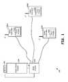
- FIG. 1is a system diagram illustrating a video game system constructed according to one or more embodiments of the present invention.
- the video game system 100 of FIG. 1includes a game console 102 and a plurality of game controllers 108 A, 108 B, and 108 C.
- the game console 102couples to an audio/visual system 104 that includes a video monitor and an audio system.
- the game console 102also couples to an infrared (IR) detector 106 .
- IRinfrared
- the game controllers 108 A, 108 B, and 108 Ccommunicate with the game console 102 via one or more of a wired and/or wireless communication link.
- the wired communication linkmay be a tethered controller including conductors that support wired communications.
- Wireless communicationsmay be in various RF frequency bands and/or in the infrared range.
- each of the game controllers 108 A, 108 B, and 108 Cincludes communication circuitry that allow the game controllers 108 A, 108 B, and 108 C to communicate with the game console 102 .
- each of game controllers 108 A, 108 B, and 108 Cincludes one or more touch pads 110 A, 110 B, and 110 C, respectively.
- the touch pads of the game controllersare used to identify users of the game controllers, to provide gaming input, to determine whether a user is active, and/or to provide other information to the game console 102 for subsequent action.
- touch padsare coupled to touch pad circuitry that captures capacitance (inductance or RF propagation) characteristics of a plurality of elements of the touch pads. Based upon the capacitive (inductive/RF) information gathered from the touch pads, a user may be identified by game console 102 and/or a game controller 108 A, 108 B, or 108 C.
- the touch pad of a particular game controllerincludes a plurality of touch pad elements, each of which measures a characteristic at the particular touch pad element/touch pad location, i.e., capacitance, inductance, RF propagation characteristics, a combination of these, etc.
- capacitance, inductance, RF propagation characteristics, and/or other local characteristics at a touch pad locationare measured over time.
- the game controller and/or game consolemay identify the particular user of the game controller. The user identity may then be used to set the characteristics of the particular game being operated or supported by the game console.
- the input received via the touch pads 110 A, 110 B, and/or 110 Cmay be used for gaming input to the game console to modify operations of the game currently being supported by a game console to modify operation of the game currently being supported by a game console.
- the input received via the touch pad 110 A, 110 B, and/or 110 Cmay be used to replace button functionality.
- the controllersmay have a back lit touch pad display that provides representations of replaced buttons, each of which corresponds to one or more touch sensitive locations.
- the plurality of touch sensitive elements of the touch pad 110 A, 110 B, and/or 110 Cmay be configured to correlate to particular user input functions. Such configurations may change over time based upon a game being played, a currently active game portion, user preferences, and/or other reasons for altering functionality of the button replacement operations of the touch pads.
- the touch padsare calibrated so as to provide accurate input and/or altered in their operation to the right improved input.
- the inventive concepts described hereinmay also be applied to/embodied by a single package video game, i.e., a video game system that is contained in a single housing.
- the video game systemincludes a display, a user input, which includes one or more touch pads, processing components, memory components, and powering components, such as a battery and power circuitry.
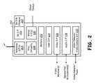
- FIG. 2is a block diagram illustrating a game console constructed according to one or more embodiments of the present invention.
- the game console 202 of FIG. 2includes a wireless interface 204 , an infrared interface 206 , an IR Transmit/Receive element 207 , processing circuitry 208 , one or more wired interfaces 210 , and memory 212 .
- the game console 202typically would also include a user interface 214 , a video interface 216 , an audio interface 218 , and may include a video camera/video camera interface 220 .
- the wireless interfaces 204support wireless communications with at least the game controllers 108 A, 108 B, and 108 C described with reference to FIG. 1 .
- This wireless interfacemay be consistent with a Bluetooth interface, a wireless local area network (WLAN) interface, or another type of wireless communication interface that supports communications between the game console 202 and game controllers. Further, the wireless interface at 204 may support communications with a WLAN router or access point, a cellular infrastructure, a satellite communications network, or another type of wireless communications systems.
- WLANwireless local area network
- the IR interface 206couples to the IR transmit/receive element 207 and supports IR communications with game controllers 108 A, 108 B, and 108 C as shown in FIG. 1 .
- the IR communications between the game console 202 and the game controllers 108 A, 108 B, and 108 Cmay support an industry standard or proprietary communications protocol.
- the processing circuitry 208may include one or more of a system processor, a digital signal processor, a processing module, dedicated hardware, application specific integrated circuit, or other circuitry that is capable of executing software instructions and for processing data.
- the memory 212may be RAM, ROM, FLASH RAM, FLASH ROM, an optical memory, magnetic memory, or other types of memory that is capable of storing data and/or instructions in allowing processing circuitry to access same.
- the wired interfaces 210may include a USB interface, a fire wire interface, a serial interface, a parallel interface, an optical interface, or another type of interface supported by a media that is copper, metal, or optical.
- the user interface 214may include keypad, video display, cursor control, touch pad, or other type of interface that allows a user to interface with the game console 202 .
- the video interface 216couples the game console 202 to one or more video monitors to provide display for the gaming environment supported by game console 202 .
- the communications link between the video interface 216 on the video monitorsmay be an HDMI interface, a composite video interface, component video interface, an S-video interface, or another type of video interface supported by both the video monitor and the game console 202 .
- the audio interface 218couples the game console 212 to speakers and/or microphones for audio content delivery and receipt.
- the video camera/video camera interface 202may include an onboard video camera or may couple the game console 202 to an external video camera. The external video camera may be used to provide gaming input or other types of information that the game console 202 uses within its operation to produce a gaming environment.
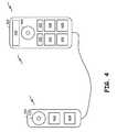
- FIG. 3Ais a first perspective view of a game controller constructed according to one or more embodiments of the present invention.
- a game controller 302includes a cursor control 304 , mechanical buttons 310 and 306 , and may include a touch pad 308 .
- the cursor control 304may be a touch pad.
- 304 and 308are both touch pads, they receive touch pad input that may be used for user identification, gaming input, or other operations supported by the gaming system and includes game controller 302 .
- FIG. 3Bis a second perspective view of the game controller 302 of FIG. 3A that is constructed according to one or more embodiments of the present invention.
- a reverse portion of the game controller 302may include a touch pad 352 .
- the touch pad 352may wrap around a back portion of the game controller 302 .
- the touch pad 352may reside on a battery cover of the game controller 302 .
- the touch pad 352includes a plurality of touch pad locations/touch sensitive elements that receive touch pad input that may be used for user ID, gaming input, and/or other purposes.
- FIG. 4illustrates a game controller and coupled secondary game controller, both of which are constructed according to one or more embodiments of the present invention.
- primary game controller 402includes a display 406 , a circular input device 408 , and button inputs 410 , 412 , 414 , 416 , 418 , and 420 . Any of these input devices 408 , 410 , 412 , 414 , 416 , 418 , and 420 of primary game controller 402 may be touch pads as is further described herein. These touch pads receive gaming inputs in a manner that is consistent with mechanical counterparts that were previously implemented according to prior devices. Further these touch pads may receive input that is used to identify a user or to provide other information.
- the primary game controller 402couples to secondary game controller 404 via either a wired or a wireless interface.
- the secondary game controller 404includes input components 421 , 422 , and 424 . These input components 421 , 422 , and 424 of the secondary game controller 404 may be embodied by either mechanical input devices or touch pads. The manner in which touch pads are implemented are described further herein. Data collected from these input components 421 , 422 , and 424 are relayed to game controller 402 , which may process the inputs. Alternately, the input received from input components 421 , 422 , and/or 424 may be relayed to a servicing game console.
- the controllers 402 and/or 404may include one or more touch pad displays as are further described herein.
- FIG. 5is a block diagram illustrating a game controller constructed according to one or more embodiments of the present invention.
- the game controller 502includes one or more wireless interfaces 504 , an IR interface 506 that includes a IR transmit/receive element 508 , processing circuitry 510 , wired interface(s) 512 , memory 514 , and user interface(s) 516 .
- These particular components of the game controller 502may be similar to the like named components of the game console 302 illustrated in FIG. 3 and described with reference thereto. However, in other embodiments, these like named components may have differing construct/functionality, e.g., smaller memory, less processing capability, lower power wireless interfaces, etc. Thus, commonly named components will not be described further herein as they have been previously described with reference to FIG. 3 .
- the game controller 502includes one or more touch pad(s) 518 , one or more touch pad display(s) 519 , motion/position detector 520 , orientation detector 522 , display 524 , speaker/microphone 526 , and a video camera 528 .
- the structure and operations of the touch pads 518will be described further herein with reference to subsequent FIGs.
- the motion/position detector 520detects motion/acceleration of the game controller 502 . Detection of such motion/acceleration may be performed in conjunction with the game controller, using a GPS system, using an accelerometer, using a gyrator, and/or using other external components to determine motion/acceleration position of the game controller.
- the motion/position detector 520may also determine position of the game controller.
- the motion/position detector 520determines the position of the game controller 502 is not described further herein. However, the position detector 520 may use external reference devices in order to determine position of the game controller within a gaming environment. Motion, acceleration, and position of the game controller 502 may be provided to a servicing game console as a gaming input.
- the orientation detector 522determines an orientation and/or direction in which the game controller is pointed. Such orientation detection provided by orientation detector 522 may be accomplished in conjunction with the IR interface 506 of the game controller 502 . Such orientation detection may be performed in conjunction with the IR detector 106 of the gaming system 100 of FIG. 1 .
- the display 524 of the game controller 502may have a relatively small size or relatively large size that presents information to a user and that allows the user to respond accordingly.
- the speaker/microphone 526may receive audio input and provide audio output to a user of the game controller 502 .
- Video camera 528 of the game controllermay be used to determine a location of the game controller and/or may be used to provide additional gaming input for gaming environments supported by the game controller 502 .
- the touch pad(s) 518 of the game controller 502may be capacitive, inductive, or RF based.
- the raw data received by a touch pad of the game controllermay be fully communicated to the game console of the gaming system.
- information captured via the touch pad(s) 518 of the game controllermay be processed by the processing circuitry 510 of the game controller 502 (or other processing circuitry) prior to communicating such information to the game console 102 of FIG. 1 .
- processingmay be full or partial to determine whether and what data to upload to the game console.
- the touch pad display(s) 519correspond to the touch pad(s) 518 and is/are operable to indicate button functionality or other functionality provided by the touch pad(s) 518 as will be described further herein with reference to FIGS. 10-16 . Further, the touch pad(s) 518 may be programmed to correspond to particular user functions, as will also be described herein with reference to FIGS. 10-16 .
- the touch pad inputs received by game controllermay be received at both primary 402 and secondary 404 game controllers of FIG. 4 .
- the inputs received from multiple touch pads on the primary and secondary game controllers 402 and 404may be received and at least partially processed by processing circuitry of the game controller(s) prior to uploading the data to a game console.
- the basis for touch pad input processingmay be based upon a current usage of the game controllers.
- the primary game controller 402may be relevant to a first portion of a user's body while the secondary game controller 404 may be relevant to a second portion of a user's body.
- teachings of the present inventionapply touch pad operations to an input device that receives data corresponding to one or more feet of a user, e.g., secondary controller 404 is a foot pad.
- a foot pattern of a usermay be employed to identify the user or to receive gaming input from the user within the gaming system.
- One purpose of using data received from one or more touch pads according to the present inventionis to identify a user of the gaming system.
- Data captured by one or more touch sensitive pads or panelsis used to distinguish a user from a plurality of users based upon finger width, finger length, finger spacing, knuckle joint location, finger angle, and other characteristics of a user's hand/fingers that is used to grasp the game controller. Identification of the user is done based upon pattern matching using various techniques. Further, the touch pad and related operations supported by the structures of the present invention may identify users based upon the heat transfer characteristics, their pulse rate characteristics, and other characteristics that would be gathered via input at a touch pad.
- a usersets-up his or her identity within the gaming system. Then, a first operation establishes correspondence between touch pad interface characteristics and the user. The gaming system may query a user to confirm that he or she is currently using the game controller with this operation by receiving input from a touch pad interface and then confirming that the particular user identity is correct. Further, the training may proceed so that it is initially intrusive and asks a number of questions of the user but then decreases its intrusions when matching registered users with touch pad input characteristics.
- the game controllermay simply automatically relate user characteristics as received from a touch pad interface with game characteristics or settings of the gaming system.
- the user identification learning processshould be as automatic as possible so as not to be burdensome to users of the system.
- the user identification system of the present inventionshould delete inactive users from the database so that they are not considered as candidates when determining whether or not a current user is one of a plurality of registered or prior users of a system.
- the touch pad input that is used to identify the usermay be used in conjunction with auxiliary information to identify a particular user.
- This auxiliary informationmay include game usage levels, game selections, time of day at which game is performed, day of week at which game is performed, gyrator input (accelerometer input), coupled secondary gaming devices or service devices, and/or additional auxiliary information. For example, one particular user may select generally games A, B and C while another user may select generally games C, D, and E. Based upon a particular game selection and data input received from a touch pad, the auxiliary information of game selection may be used to further identify the user that is currently using the gaming system.
- a particular usermay only use the system during certain times of the day or days of the week and such information is further used to determine identity of the user of the gaming system.
- some usersmay only use certain auxiliary devices such as nun chucks, guitars, drums, car driving accessories, plane control accessories, or other coupled devices of the game controllers.
- the operations of the present inventionmay use the fact that these devices are coupled to further limit the number of potential users that are considered for identification at a particular time.
- a user IDis employed to enact a user's custom game data or settings for the gaming system. For example, a particular user is identified and this user's game selection, game settings, and other preferences that have been previously inputted into the game system are automatically enacted.
- the gaming environment settingsare altered based upon such identification. For example, once the user is identified, the game difficulty level, game entry point, game controller button functions, game controller touch sensitive panel gaming input functions, and/or other custom settings of the gaming system may be altered.
- a sequence of touches on the touch sensitive panelmay alter some game operation or game selection operations.
- menus and other user input selectionsmay be altered after a user is identified. For example, the user may have previously indicated that he or she only wants to employ certain games. Once that user is identified then the gaming system would only give that particular user the option of selecting from a list of previously selected games. Further, the user may have customized the menu of the gaming system previously. When the user identified them the customized user interface of the gaming system is enacted.
- the touch pad interfaceis able to determine a relative hand position of the user of the game controller. For example, some types of video games such as tennis or golf require that a user hold the game controller at a particular position. While other games require that the user holds the game controller at a differing position.
- the game controller and/or the game consoleis able to determine what position that the user is holding on the game controller. Once this position is identified, the game controller/game console is able to limit the types of games that the user may play based upon the position of the hand with regard to the position of the controller. Thus, the game is customized to some degree based upon a hand position of the user with respect to the controller.
- input received via touch sensitive pads or panelsmay be used for gaming input.
- the touch sensitive panelsmay be used to determine that a user has changed his or her hand or finger positions, changed his or her grip positions or otherwise abruptly changed an input to a game controller that is used within a gaming system.
- Such detectionmay be used with one scanning rate of the touch sensitive panel.
- the scanning rate of the touch sensitive panelmay be altered based upon a game being played. For example, when the game being played is one that has minimal input requirements the scanning rate may be relatively lower. However, when a game is being played that has a relatively higher input rate such as a fitness program, the scanning rate of one or more touch sensitive panels of one or more game controllers may be increased.
- scanning of one or more of the touch sensitive panelsmay be enabled for some portions of the game while not enabled for another portion of the game.
- grip/finger position movement or pressure changesmay be enabled during a first portion of the game and not enabled for other portions of the game. Such is the case because the particular gaming input that is being sensed by changing finger position or grip pressure is only relevant during some portions of the game and not others.
- the gaming inputmay be based upon a change from a prior hand position or a prior relationship between the hand and the game controller and a current position of the hand with respect to the game controller. For example also, a baseline position for the hand with respect to the game controller may be established during a baseline mode of operation. Then, any alteration of the position of the hand with respect to the game controller will serve as a differing gaming input while operation of the game progresses.
- each of a plurality of one or more touch sensitive panels of the game controllermay be reconfigured by the game console based upon a game being played. Because each game being played may have particular gaming input requirements, the configuration of the touch sensitive panel may be required to be customized for the particular game being played so that the gaming input is most relevant to the particular game. For example, a game in which the touch sensitive panel provides multiple types of input to the game may require a configuration of the touch sensitive panel other than when the game controller touch pad only indicates whether or not the user has picked up the game controller. Further, configuration of the touch sensitive panels may be selected by a user based upon the gaming parameters and/or the configuration of the gaming panels may change at a particular gaming point based upon a selection of the user.
- a configuration of touch panel functionsmay be based upon the orientation of a controller. For example, when a golf, baseball, tennis or sword input is selected, the touch panel functions may differ for each of the particular types of games. Such is the case because the game controller may be held in different relative positions with respect to the hands for each of these types of games. Thus, the manner in which the touch panels provide gaming input will change based upon not only orientation of the controller but with regard to its simulated game piece function.
- each particular gamemay have its own particular touch input language that implements particular game function(s).
- Such game touch input languagemay be considered as a sequence of touches with the touches in particular portions of the touch sensitive panel providing input to the game.
- the sequence of touches provided to the touch sensitive panelis similar to those that may be provided via sequence of button selections via mechanical buttons of the prior game controller.
- the touch sensitive panel of the present invention game controlleris very configurable and not limited by mechanical button limitations, the touch sensitive panel may be configured at different points in time to have particular touch sequence input functions. This sequence of touch pad inputs may be similar to keypad shortcuts and may be customized by a user.
- game controller and game console functionalityis merged into a single device, i.e., all-in-one video game platform.
- This devicewill also include a display that user views when playing a game supported by the device.
- the teachings described herein as being jointly performed by a game controller and game consolemay be accomplished by such a single unit device.
- FIG. 6is a block diagram illustrating a touch sensitive pad and touch pad circuitry constructed according to one or more embodiments of the present invention.
- a touch pad 602includes a plurality of touch sensitive elements 604 each of which corresponds to a particular location of the touch pad 602 .
- the touch padincludes an array of touch sensitive elements 604 , each of which may be a particular capacitively coupled location, inductively coupled location, or a radio frequency (RF) touch sensitive element.
- Touch pad circuitry 606couples via a grid structure to the plurality of touch sensitive elements 604 to sense the particular capacitance, inductive, or RF characteristics at each of the touch sensitive elements.
- Touch pad circuitry 606scans the plurality of touch sensitive elements 604 via access of particular row-column combinations at particular times.
- the frequency or voltage at which the touch pad circuitry 606 scans the plurality of touch sensitive elements 604may be altered over time. Choosing the scanning frequency or scanning voltage may be based upon a particular operational use of the touch pad. For example, at some points in time the manner in which the touch pad is scanned will change based upon a particular point in a game of a gaming system with which the touch pad functions as a gaming input device. Further, a first scanning frequency/scanning voltage may be employed for user identification while a second scanning frequency/scanning voltage may be employed for gaming input functions.
- the scanning done by the touch pad circuitry 606 of the plurality of touch sensitive elements 604may be made using a spread spectrum frequency scanning technique. Such technique may be employed to more efficiently capture information from the touch pad 602 at the various touch sensitive elements 604 or to determine which particular scanning frequencies are more successful than others in capturing input information.
- each row and column corresponding to a particular touch sensitive element 604may be altered based upon a detected capacitance (inductance/RF propagation) at the location.
- a detected capacitanceinductance/RF propagation
- one particular touch sensitive element 604may have a fixed capacitance that does not vary over time. Such fixed capacitance may indicate that the particular touch sensitive element 604 is inoperable or that it receives no discernible input. In such case, by not scanning the particular touch sensitive element, other touch sensitive elements may be more frequently scanned or energy may be saved by not scanning all touch sensitive elements.
- some portions of the touch padmay be disabled while others are enabled at differing points in time. Enablement of some touch sensitive elements and not others may be based upon a custom configuration of the touch pad for a particular input function provided.
- the touch pad 602may also be calibrated by the touch pad circuitry 606 based upon the environmental factors such as temperature, humidity, and surrounding noise from the capacitance, inductance, or RF perspective. Calibration of the touch pad 602 allows the touch pad 602 to have more efficient and effective touch pad input for user identification and/or for other input purposes.
- the touch pad 602may also be calibrated by the touch pad circuitry 606 based upon the environmental factors such as temperature, humidity, and surrounding noise as detected by measured capacitance, inductance, or RF propagation characteristics. Calibration of the touch pad 602 allows the touch pad 602 to be more efficient and more effectively receive touch pad input for user identification and/or for other input purposes.
- the calibration of the touch pad 602 by the touch pad circuitry 606may be initiated at particular points in time.
- the touch pad circuitry 606may simply initiate calibration of the touch pad 602 upon the expiration of a timer such that the touch pad is calibrated at a particular regular time interval.
- the touch pad 602may be calibrated after a period of inactivity, i.e., the touch pad circuitry 606 performs calibration when it determines that no input is present on the touch pad 602 .
- the touch pad 602may be calibrated by the touch pad circuitry 606 using other input criteria as well.
- FIG. 7Ais a diagram illustrating how a user's hand may overlay a touch pad according to one or more embodiments of the present invention.
- the touch pad 602has a plurality of touch sensitive elements 604 and is mounted upon a portion of a vehicle so that it is adjacent a user's hand when the user holds the portion of the vehicle.
- the outline 702 of users handis shown as overlaying the touch pad 602 and the plurality of touch sensitive elements 604 . While the touch pad 602 of FIG. 7A is generally illustrated as planar, the touch pad 602 may wrap around a steering wheel, gear shifter, door handle, or another vehicle component.
- FIG. 7Bis a diagram illustrating the manner in which a user's hand upon the touch pad produces a particular pattern of capacitance (inductance/RF propagation) upon the touch pad.
- a relative capacitance, inductance, or RF propagation pattern of the user's hand 702is shown on touch pad 602 .
- the depiction in FIG. 7Bis illustrated in general only of relative capacitance at each of the user's finger location positions upon the touch pad 602 . For example, where the user's fingers touch physically the touch pad 602 , stronger capacitance lines 752 and 754 are shown. Where the user's fingers overlay the touch pad 602 , lesser capacitance, inductance, or RF propagation characteristic lines 754 are shown. While other capacitance lines on the touch pad 602 are not shown in FIG. 7B are numbered, the various capacitance lines would be present for the other fingers as well.
- the capacitance pattern of the user's hand 702 upon the touch pad 602is a signature of a particular user.
- differing userscan be identified.
- the touch pad 602may serve as an input device, the capacitance of the touch sensitive elements 604 of the touch pad of 602 over time as it varies may be used to indicate touch pad input.
- the characteristics measured at each touch sensitive element 604 over timewill enable the device to identify a user or to try particular input via the touch pad 602 .
- each of a plurality of touch sensitive pads of the game controllermay be reconfigured by the game console based upon a game being played. Because each game being played may have particular gaming input requirements, the configuration of the touch pad may be required to be customized for the particular game being played so that the gaming input is most relevant to the particular game. For example, a game in which the touch pad provides multiple types of input to the game may require a configuration of the touch pad other than when the game controller touch pad only indicates whether or not the user has picked up the game controller. Further, configuration of the touch pads may be selected by user based upon the gaming parameters. For example, the configuration of the gaming panels may change at a particular game point based upon a selection of the user.
- configuration of touch pad functionsmay be based upon the orientation of a controller. For example, when a golf, baseball, tennis or sword input is selected, the touch pad functions may differ for each of the particular types of games. Such is the case because the game controller may be held in different relative positions with respect to the hands for each of these types of games. Thus, the manner in which the touch pads provide gaming input will change based upon not only orientation of the controller but with regard to its simulated game piece function.
- each particular gamemay have its own particular touch input language that implements particular game function(s).
- Such game touch input languagemay be considered as a sequence of touches with the touches in particular portions of the touch pad providing input to the game.
- the sequence of touches provided to the touch padis similar to those that may be provided via sequence of button selections via mechanical buttons of the prior game controller.
- the touch pad of the present invention game controlleris very configurable and not limited by mechanical button limitations, the touch pad may be configured at different points in time to have particular touch sequence input functions.
- FIGS. 1-6can singularly or jointly perform the operations of the following FIGS. 8-16 .
- processing performedis not identified as being performed by a particular device. In such case the processing may be performed by one or both of a game controller and/or a game console. In other operations the processing or operations performed are attributed to one of a game console or game controller. In such cases, the processing could alternatively be performed by the other of the game console or game controller or jointly by the game console and game controller. In still other embodiments, the operations of FIGS. 8-16 are performed by a single case video gaming system.
- the operations of the touch pad circuitry 606change based upon its operational condition.
- the touch pad configuration settings that correlate subsets of a plurality of touch sensitive elementscan be enacted to respective distinct user input locations.
- Touch pad inputis received from at least one touch sensitive pad.
- the touch pad inputcorresponds to a user's touch of at least some of the plurality of touch sensitive elements.
- the touch pad inputis processed to determine user input directions based upon the touch pad configuration settings.
- the user input directionsare transmitted to a game console via the communications interface for use as gaming input.
- FIG. 8is a flowchart illustrating operations 800 of a game controller and a game console to receive and process touch pad input according to one or more embodiments of the present invention.
- the operations 800 of FIG. 8begin when touch pad input is received from at least one touch sensitive pad of a game controller, step 802 .
- the at least one touch sensitive pad of a game controllerhas a plurality of touch sensitive elements. Each of these touch sensitive elements is individually scanned to detect capacitance, inductance, or RF propagation characteristics of the touch sensitive element.
- the touch pad inputcorresponds to a user's touch of at least some of the plurality of touch sensitive elements.
- the touch pad inputis processed by processing circuitry of the game controller, step 804 .
- the game controllermay perform first processing operations on the touch pad input and transmit the touch pad input to the game console for second processing operations such that processing operations on the touch pad input are shared between the game controller and the game console. Alternately the game controller may simply transmit raw touch pad input to the game console for processing. In still other operations, all processing of the touch pad input is performed by the game controller.
- the at least partially processed touch pad inputis transmitted to the game console via a communications interface of the game controller, step 806 .
- the game consoleprocesses the touch pad input for user identification, gaming input, game operation alterations (e.g. power down game, pause game, game settings, and the like), step 808 .
- the game consolemay then direct the game controller to alter its operations at step 810 , including altering operations of the touch sensitive pad.
- FIG. 9is a flowchart illustrating other operations 900 of a game controller and a game console to receive and process touch pad input according to one or more embodiments of the present invention.
- Operations 900begin with receiving first touch pad input from a first touch sensitive pad of a game controller, step 902 .
- First touch pad inputis received via a first touch pad that has a first plurality of touch sensitive elements.
- Second touch pad inputis then received from a second touch pad of the game controller or from a touch pad of a second game controller that communicatively couples to the first game controller, step 904 .
- the second touch pad inputis separate and distinct from the first touch pad input.
- the first and second touch pad inputsare processed and/or combined to produce combined touch pad input, step 906 .
- the first touch pad inputmay be user finger touch pad input, user thumb touch pad input, user hand touch pad input, or a combination of these.
- the user finger touch pad inputcan be combined with the user thumb touch pad input to produce combined user touch pad input.
- the first touch pad inputmay be captured by a touch pad of the first game controller and the second touch pad input may be captured by a touch pad of the second game controller and combined to produce the combined touch pad input.
- the first touch pad inputmay be from a first hand of a user and the second touch pad input may be from a second hand of the user (or from the hand of another user).
- the first touch pad inputmay be of a hand of the user and the second touch pad input may be of a foot of the user.
- teachings of the present inventionapply to other combinations of input(s) as well.
- the combined touch pad inputis transmitted to the game console via a communications interface of the game controller, step 908 .
- the game consoleuses the touch pad input for user identification, gaming input, game operation alterations (e.g. power down game, pause game, game setting, and the like), step 910 .
- the game consolemay direct the game controller to alter operations of at least one touch sensitive pad, step 912 .
- initial operational parametersare set for the least one touch sensitive pad of the game controller by either the game controller or the game console. Based upon further input received by the game controller, the operations of the touch sensitive pad are altered. It is understood that the game console could make the decision to direct the game controller to alter operations of at least one touch sensitive pad, as will be described herein, even though the game controller may make such operational decisions alone.
- FIG. 10is a flowchart illustrating other operations 1000 of a game controller and a game console to receive and process touch pad input according to one or more embodiments of the present invention.
- the game controllerhas a communications interface, at least one touch sensitive pad having a plurality of touch sensitive elements, and processing circuitry coupled to the communications interface and to the at least one touch sensitive pad.
- Operations 1000begin with touch pad configuration settings being enacted that correlate subsets of the plurality of touch sensitive elements to respective distinct user input locations, step 1002 . These touch pad configuration settings may have been received from the game console in a touch pad configuration settings message. Alternately, when the game controller is an all in one device, the touch pad configuration settings may be internally generated.
- Touch pad inputis received from the touch sensitive pad of the game controller, step 1004 .
- the touch pad inputcorresponds to a user's touch of at least some of the plurality of touch sensitive elements.
- the touch pad inputis processed based upon the touch pad configuration settings to determine user input directions, step 1006 .
- the user input directionsare determined by the game controller based upon both the user's touch of one or more particular touch sensitive elements of the touch pad and the touch pad configuration settings, which correlate subsets of the plurality of touch sensitive elements to respective distinct user input locations.
- the user input directionsmay be gaming input, keypad input, or other input, even though referred to as “gaming input” herein.
- the touch pad configuration settingscorrelate the touch sensitive elements, each of which correlates to a particular location of the touch pad to user input functions.
- touch pad configuration settingscause a correspondence to exist between particular touch sensitive elements and each of the North-South-East-West button functions.
- the game controllerreceives the touch pad input at step 1004 and processes the touch pad input at step 1006 to determine how the touch pad input causes the user input functions.
- Some touch pad inputcauses the user input function to correlate to a “North” button depression.
- Other touch pad inputcauses the user input function to correlate to a “South” button depression.
- the touch pad configuration settingscould cause the touch pad to have differing button replacement functionality as well, causing equivalent touch pad input to result in differing user input directions.
- touch pad configuration settingsare then enacted that correlate different subsets of the plurality of touch sensitive elements to different distinct user input locations, step 1010 .
- the touch pad configuration settingscan be determined from/received in a touch pad configuration settings message received from the game console.
- the other touch pad configuration settingsdiffer from the touch pad configuration settings.
- These other touch pad configuration settingsmay be enacted upon reaching a differing portion of a video game, upon playing a different video game, upon exiting or entering a video game, or based upon a different input function phase of usage of the game controller.
- These other touch pad configuration settingsmay be enacted based upon receipt of another touch pad configuration settings message received from the game console via the communications interface.
- Touch pad inputis then received from the touch sensitive pad of the game controller, step 1012 .
- the touch pad inputis processed based upon the different touch pad configuration settings to determine other user input directions, step 1014 .
- the other user input directionsare transmitted to the game console via communications interface, step 1016 .
- FIG. 11is a flowchart illustrating other operations 1100 of a game controller and a game console to receive and process touch pad input according to one or more embodiments of the present invention.
- Operations 1100begin with first touch pad configuration settings being selected by the game console for a first video game/first video game portion/first grip position, step 1102 .
- the game consoledirects the game controller to enact first touch pad configuration settings using a touch pad configuration settings message, for example, step 1104 .
- the game consolereceives user input directions that are based upon first touch pad configuration settings, step 1106 .
- the game consolenext selects second touch pad configuration settings for second video game/second video game portion/second grip position, step 1108 .
- the game consoledirects the game controller to enact second touch pad configuration settings, in a touch pad configuration settings message, for example, step 1110 .
- the game consolethen receives user input directions that are based upon second touch pad configuration settings, step 1112 .
- the touch pad configuration settingscorrelate subsets of the plurality of touch sensitive elements to respective distinct user input locations.
- identical touch pad input received at a touch padcould result in differing user input directions for differing touch pad configuration settings.
- Such operationsare beneficial in that the same touch pad may be used to support many different input functions, solely by altering the touch pad configuration settings.
- FIG. 12is a flowchart illustrating operations 1200 of a game controller to receive and process touch pad input and to control a touch pad display according to one or more embodiments of the present invention.
- the touch pad displayhas a plurality of display elements that may be configured to display at least one simulated button. Each simulated button corresponds to a plurality of touch sensitive elements.
- the processing circuitrycauses the at least one simulated button to be illuminated by the touch pad display.
- the game controllerreceives a touch pad configuration message and determines touch pad configuration settings, including a touch pad display configuration, step 1202 .
- the game controllerenacts the touch pad display configuration, step 1204 .
- the game controllerreceives touch pad input, and processes the touch pad input based upon the touch pad configuration settings, step 1206 .
- the game controllerreceives another touch pad configuration message and determines other touch pad configuration settings that include another touch pad display configuration, step 1208 .
- the game controllerenacts other touch pad display configuration, step 1210 .
- the game controllerreceives other touch pad input, and processes the other touch pad input based upon other touch pad configuration settings, step 1212 .
- the touch pad displayis employed to cause button functionality and/or other input functionality to be represented in conjunction with the touch pad.
- This button functionalityallows the touch pad to be configured and reconfigured for differing uses with different video games, different portions of a video game, for non-gaming functions, and for other functions.
- FIG. 13is a flowchart illustrating other operations 1300 of a game controller and a game console to select and direct touch pad configuration settings according to one or more embodiments of the present invention.
- Touch pad configuration settingsare enacted that correlate subsets of the plurality of touch sensitive elements to respective distinct user input locations.
- the processing circuitryenacts first touch pad configuration settings for a first grip position of the game controller, and enacts second touch pad configuration settings for a second grip position of the game controller.
- the first touch pad configuration settingscan be enacted when the game controller emulates a first gaming piece.
- the second touch pad configuration settingscan be enacted when the game controller emulates a second gaming piece that differs from the first gaming piece.
- the gaming piecescan be one or more of a golf club, a tennis racquet, a baseball bat, a sword, a guitar, a gun, and a knife.
- operations 1300begin with the game console selecting first touch pad configuration settings for first grip position/first gaming piece emulation, step 1302 .
- the game consoledirects the game controller to enact first touch pad configuration settings, step 1304 .
- the game consolereceives user input directions that are based upon first touch pad configuration settings, step 1306 .
- the game consoleselects second touch pad configuration settings for second grip position/second gaming piece emulation, step 1308 .
- the game consoledirects game controller to enact second touch pad configuration settings, step 1310 .
- the game consolereceives user input directions that are based upon second touch pad configuration settings, step 1312 , and the process ends.
- FIG. 14is a diagram illustrating a touch pad including a plurality of display elements of a touch pad display that are controllable to illustrate elements corresponding to buttons or other components of a game controller according to one or more embodiments of the present invention.
- the touch sensitive pad 1402includes a plurality of touch sensitive elements 1404 and also includes the ability of the touch sensitive pad to serve as a button replacement device.
- a touch sensitive display corresponding to the touch sensitive pad 1402has a plurality of display elements operable to represent buttons visually to a user, the buttons corresponding to a mechanical game control input pattern.
- Such patternincludes indicated touch locations 1406 , 1408 , 1410 , 1412 , and 1414 . Such locations may correspond to a mechanical game control input pattern that is subsequently used for gaming input.
- each of these simulated buttons 1406 - 1414may have a particular game input control function and serve as such via the touch sensitive pad 1402 .
- each of the touch sensitive pads if there are multiple of the touch sensitive pads on the game controllermay replace button functions of prior controllers.
- North, South, East, West directional controlreplaces a similar function mechanical control.
- Each of the touch sensitive pads 1402may have a control touch pad display to indicate the button positions and functionality of each for the simulated mechanical input functions replaced by the touch sensitive pad 1402 .
- FIG. 15is another diagram illustrating a game controller with display elements of the touch pad display configured differently than those in FIG. 14 .
- the second configuration of the touch sensitive pad 1402 with a differing illumination of display elementsincludes simulated buttons or touch locations 1506 , 1508 , 1510 , 1512 , and 1514 - 1516 .
- the touch sensitive pad 1402 and its plurality of touch sensitive elements 1404has been reconfigured to another set of input locations or devices.
- the touch sensitive pad 1402may be reconfigured by a game console, the game controller itself, or remote control based upon a game being played or based upon a particular desire configuration of the touch sensitive pads to simulate mechanical input components or to simply be a customized touch sensitive pad interface.
- the touch sensitive pad 1402may be configured by the user based upon a preference for game parameter inputs. Alternatively, the touch sensitive pad 1402 may be customized based upon the particular game being played so that it has functionality for input corresponding to the particular game itself. For example, the configuration of the touch sensitive pad 1402 functions may be based upon an orientation of the controller and how it relates to the particular game being played, e.g., golf, baseball, tennis, a sword input, etc. Further, when the touch sensitive pad 1402 is configured for specialized operations so as to depict particular buttons that are available to be depressed, the touch sensitive elements 1404 may be selectively scanned as to only provide input or receive input from the touch sensitive elements 1404 corresponding to particular buttons. As an example of FIG. 15 , the touch sensitive pad 1402 may be scanned so as to only scan touch sensitive elements 1404 corresponding to buttons 1506 , 1508 , 1510 , 1512 , and 1514 - 1516 .
- FIG. 16is a diagram illustrating a touch sensitive pad, a touch pad display, touch pad circuitry and touch pad display circuitry constructed according to one or more embodiments of the present invention.
- a touch sensitive pad 1402includes a plurality of touch sensitive elements 1404 , each of which corresponds to a particular location of the touch sensitive pad 1402 .
- Touch pad circuitry 1606couples to the plurality of touch sensitive elements 1404 , and to processing circuitry 510 and touch pad display circuitry 1608 .
- Touch pad circuitry 1606scans the plurality of touch sensitive elements 1604 .
- the touch pad displayincludes a plurality of touch pad display elements 1604 that may be selectively controlled to create buttons and/or other icons to a user, such buttons and/or other icons relating to corresponding touch pad elements.
- Touch pad configuration settingsare enacted that correlate subsets of the plurality of touch sensitive elements 1404 to respective distinct user input locations.
- the respective distinct user input locationsmay be indicated by the touch pad display elements 1604 indications.
- the processing circuitry 510enacts touch pad configuration settings that were previously described herein.
- the processing circuitry 510causes the touch pad circuitry 1606 and/or the touch pad display circuitry 1608 to operate particularly based upon the touch pad configuration settings.
- the processing circuitry 510enacts first touch pad configuration settings for a first grip position of the game controller, and enacts second touch pad configuration settings for a second grip position of the game controller.
- the first touch pad configuration settingscan be enacted when the game controller emulates a first gaming piece.
- the second touch pad configuration settingscan be enacted when the game controller emulates a second gaming piece that differs from the first gaming piece.
- the gaming piecescan be one or more of a golf club, a tennis racquet, a baseball bat, a sword, a guitar, a gun, and a knife.
- circuitand “circuitry” as used herein may refer to an independent circuit or to a portion of a multifunctional circuit that performs multiple underlying functions.
- processing circuitrymay be implemented as a single chip processor or as a plurality of processing chips.
- a first circuit and a second circuitmay be combined in one embodiment into a single circuit or, in another embodiment, operate independently perhaps in separate chips.
- chiprefers to an integrated circuit. Circuits and circuitry may comprise general or specific purpose hardware, or may comprise such hardware and associated software such as firmware or object code.
- the terms “substantially” and “approximately”provides an industry-accepted tolerance for its corresponding term and/or relativity between items. Such an industry-accepted tolerance ranges from less than one percent to fifty percent and corresponds to, but is not limited to, component values, integrated circuit process variations, temperature variations, rise and fall times, and/or thermal noise. Such relativity between items ranges from a difference of a few percent to magnitude differences.
- the term(s) “coupled to” and/or “coupling” and/orincludes direct coupling between items and/or indirect coupling between items via an intervening item (e.g., an item includes, but is not limited to, a component, an element, a circuit, and/or a module) where, for indirect coupling, the intervening item does not modify the information of a signal but may adjust its current level, voltage level, and/or power level.
- an intervening iteme.g., an item includes, but is not limited to, a component, an element, a circuit, and/or a module
- inferred couplingincludes direct and indirect coupling between two items in the same manner as “coupled to.”
- operble toindicates that an item includes one or more of power connections, input(s), output(s), etc., to perform one or more its corresponding functions and may further include inferred coupling to one or more other items.
- associated withincludes direct and/or indirect coupling of separate items and/or one item being embedded within another item.
- compares favorablyindicates that a comparison between two or more items, signals, etc., provides a desired relationship. For example, when the desired relationship is that signal 1 has a greater magnitude than signal 2, a favorable comparison may be achieved when the magnitude of signal 1 is greater than that of signal 2 or when the magnitude of signal 2 is less than that of signal 1.
Landscapes
- Engineering & Computer Science (AREA)
- Theoretical Computer Science (AREA)
- General Engineering & Computer Science (AREA)
- Computer Security & Cryptography (AREA)
- Physics & Mathematics (AREA)
- General Physics & Mathematics (AREA)
- Computer Hardware Design (AREA)
- Software Systems (AREA)
- Human Computer Interaction (AREA)
- User Interface Of Digital Computer (AREA)
- Position Input By Displaying (AREA)
- Navigation (AREA)
Abstract
Description
Claims (27)
Priority Applications (2)
| Application Number | Priority Date | Filing Date | Title |
|---|---|---|---|
| US12/912,645US8449393B2 (en) | 2009-11-16 | 2010-10-26 | Hand-held gaming device with configurable touch sensitive panel(s) |
| US13/867,316US8845424B2 (en) | 2009-11-16 | 2013-04-22 | Hand-held gaming device with configurable touch sensitive panel(s) |
Applications Claiming Priority (2)
| Application Number | Priority Date | Filing Date | Title |
|---|---|---|---|
| US26170209P | 2009-11-16 | 2009-11-16 | |
| US12/912,645US8449393B2 (en) | 2009-11-16 | 2010-10-26 | Hand-held gaming device with configurable touch sensitive panel(s) |
Related Child Applications (1)
| Application Number | Title | Priority Date | Filing Date |
|---|---|---|---|
| US13/867,316ContinuationUS8845424B2 (en) | 2009-11-16 | 2013-04-22 | Hand-held gaming device with configurable touch sensitive panel(s) |
Publications (2)
| Publication Number | Publication Date |
|---|---|
| US20110118028A1 US20110118028A1 (en) | 2011-05-19 |
| US8449393B2true US8449393B2 (en) | 2013-05-28 |
Family
ID=44010905
Family Applications (12)
| Application Number | Title | Priority Date | Filing Date |
|---|---|---|---|
| US12/894,011Active2031-03-08US8535133B2 (en) | 2009-11-16 | 2010-09-29 | Video game with controller sensing player inappropriate activity |
| US12/912,405Active2032-05-21US8614621B2 (en) | 2009-11-16 | 2010-10-26 | Remote control for multimedia system having touch sensitive panel for user ID |
| US12/912,637AbandonedUS20110115606A1 (en) | 2009-11-16 | 2010-10-26 | Touch sensitive panel in vehicle for user identification |
| US12/912,651AbandonedUS20110118029A1 (en) | 2009-11-16 | 2010-10-26 | Hand-held gaming device with touch sensitive panel(s) for gaming input |
| US12/912,472AbandonedUS20110115741A1 (en) | 2009-11-16 | 2010-10-26 | Touch sensitive panel supporting stylus input |
| US12/912,595AbandonedUS20110118027A1 (en) | 2009-11-16 | 2010-10-26 | Altering video game operations based upon user id and-or grip position |
| US12/912,422AbandonedUS20110118025A1 (en) | 2009-11-16 | 2010-10-26 | Game controller with touch pad user interface |
| US12/912,645Expired - Fee RelatedUS8449393B2 (en) | 2009-11-16 | 2010-10-26 | Hand-held gaming device with configurable touch sensitive panel(s) |
| US12/912,342AbandonedUS20110118024A1 (en) | 2009-11-16 | 2010-10-26 | Adjusting operation of touch sensitive panel of game controller |
| US12/943,768Active2033-02-04US8838060B2 (en) | 2009-11-16 | 2010-11-10 | Device communications via intra-body communication path |
| US12/945,556Active2031-09-08US9007331B2 (en) | 2009-11-16 | 2010-11-12 | Touch sensitive panel detecting hovering finger |
| US13/867,316ActiveUS8845424B2 (en) | 2009-11-16 | 2013-04-22 | Hand-held gaming device with configurable touch sensitive panel(s) |
Family Applications Before (7)
| Application Number | Title | Priority Date | Filing Date |
|---|---|---|---|
| US12/894,011Active2031-03-08US8535133B2 (en) | 2009-11-16 | 2010-09-29 | Video game with controller sensing player inappropriate activity |
| US12/912,405Active2032-05-21US8614621B2 (en) | 2009-11-16 | 2010-10-26 | Remote control for multimedia system having touch sensitive panel for user ID |
| US12/912,637AbandonedUS20110115606A1 (en) | 2009-11-16 | 2010-10-26 | Touch sensitive panel in vehicle for user identification |
| US12/912,651AbandonedUS20110118029A1 (en) | 2009-11-16 | 2010-10-26 | Hand-held gaming device with touch sensitive panel(s) for gaming input |
| US12/912,472AbandonedUS20110115741A1 (en) | 2009-11-16 | 2010-10-26 | Touch sensitive panel supporting stylus input |
| US12/912,595AbandonedUS20110118027A1 (en) | 2009-11-16 | 2010-10-26 | Altering video game operations based upon user id and-or grip position |
| US12/912,422AbandonedUS20110118025A1 (en) | 2009-11-16 | 2010-10-26 | Game controller with touch pad user interface |
Family Applications After (4)
| Application Number | Title | Priority Date | Filing Date |
|---|---|---|---|
| US12/912,342AbandonedUS20110118024A1 (en) | 2009-11-16 | 2010-10-26 | Adjusting operation of touch sensitive panel of game controller |
| US12/943,768Active2033-02-04US8838060B2 (en) | 2009-11-16 | 2010-11-10 | Device communications via intra-body communication path |
| US12/945,556Active2031-09-08US9007331B2 (en) | 2009-11-16 | 2010-11-12 | Touch sensitive panel detecting hovering finger |
| US13/867,316ActiveUS8845424B2 (en) | 2009-11-16 | 2013-04-22 | Hand-held gaming device with configurable touch sensitive panel(s) |
Country Status (1)
| Country | Link |
|---|---|
| US (12) | US8535133B2 (en) |
Cited By (29)
| Publication number | Priority date | Publication date | Assignee | Title |
|---|---|---|---|---|
| US10262324B2 (en) | 2010-11-29 | 2019-04-16 | Biocatch Ltd. | System, device, and method of differentiating among users based on user-specific page navigation sequence |
| US10298614B2 (en)* | 2010-11-29 | 2019-05-21 | Biocatch Ltd. | System, device, and method of generating and managing behavioral biometric cookies |
| US10397262B2 (en) | 2017-07-20 | 2019-08-27 | Biocatch Ltd. | Device, system, and method of detecting overlay malware |
| US10404729B2 (en) | 2010-11-29 | 2019-09-03 | Biocatch Ltd. | Device, method, and system of generating fraud-alerts for cyber-attacks |
| US10474815B2 (en) | 2010-11-29 | 2019-11-12 | Biocatch Ltd. | System, device, and method of detecting malicious automatic script and code injection |
| US10523680B2 (en) | 2015-07-09 | 2019-12-31 | Biocatch Ltd. | System, device, and method for detecting a proxy server |
| US10579784B2 (en) | 2016-11-02 | 2020-03-03 | Biocatch Ltd. | System, device, and method of secure utilization of fingerprints for user authentication |
| US10586036B2 (en) | 2010-11-29 | 2020-03-10 | Biocatch Ltd. | System, device, and method of recovery and resetting of user authentication factor |
| US20200110478A1 (en)* | 2018-10-08 | 2020-04-09 | Interface Technology (Chengdu) Co., Ltd. | Touch device |
| US10621585B2 (en) | 2010-11-29 | 2020-04-14 | Biocatch Ltd. | Contextual mapping of web-pages, and generation of fraud-relatedness score-values |
| US10685355B2 (en) | 2016-12-04 | 2020-06-16 | Biocatch Ltd. | Method, device, and system of detecting mule accounts and accounts used for money laundering |
| US10719765B2 (en) | 2015-06-25 | 2020-07-21 | Biocatch Ltd. | Conditional behavioral biometrics |
| US10728761B2 (en) | 2010-11-29 | 2020-07-28 | Biocatch Ltd. | Method, device, and system of detecting a lie of a user who inputs data |
| US10747305B2 (en) | 2010-11-29 | 2020-08-18 | Biocatch Ltd. | Method, system, and device of authenticating identity of a user of an electronic device |
| US10776476B2 (en) | 2010-11-29 | 2020-09-15 | Biocatch Ltd. | System, device, and method of visual login |
| US10834590B2 (en) | 2010-11-29 | 2020-11-10 | Biocatch Ltd. | Method, device, and system of differentiating between a cyber-attacker and a legitimate user |
| US10897482B2 (en) | 2010-11-29 | 2021-01-19 | Biocatch Ltd. | Method, device, and system of back-coloring, forward-coloring, and fraud detection |
| US10917431B2 (en)* | 2010-11-29 | 2021-02-09 | Biocatch Ltd. | System, method, and device of authenticating a user based on selfie image or selfie video |
| US10949514B2 (en) | 2010-11-29 | 2021-03-16 | Biocatch Ltd. | Device, system, and method of differentiating among users based on detection of hardware components |
| US10949757B2 (en) | 2010-11-29 | 2021-03-16 | Biocatch Ltd. | System, device, and method of detecting user identity based on motor-control loop model |
| US10970394B2 (en) | 2017-11-21 | 2021-04-06 | Biocatch Ltd. | System, device, and method of detecting vishing attacks |
| US11055395B2 (en) | 2016-07-08 | 2021-07-06 | Biocatch Ltd. | Step-up authentication |
| US20210329030A1 (en)* | 2010-11-29 | 2021-10-21 | Biocatch Ltd. | Device, System, and Method of Detecting Vishing Attacks |
| US11210674B2 (en) | 2010-11-29 | 2021-12-28 | Biocatch Ltd. | Method, device, and system of detecting mule accounts and accounts used for money laundering |
| US11223619B2 (en) | 2010-11-29 | 2022-01-11 | Biocatch Ltd. | Device, system, and method of user authentication based on user-specific characteristics of task performance |
| US11269977B2 (en) | 2010-11-29 | 2022-03-08 | Biocatch Ltd. | System, apparatus, and method of collecting and processing data in electronic devices |
| US11606353B2 (en) | 2021-07-22 | 2023-03-14 | Biocatch Ltd. | System, device, and method of generating and utilizing one-time passwords |
| US20230143009A1 (en)* | 2020-02-14 | 2023-05-11 | Valve Corporation | Dynamically enabling or disabling controls of a controller |
| US20240080339A1 (en)* | 2010-11-29 | 2024-03-07 | Biocatch Ltd. | Device, System, and Method of Detecting Vishing Attacks |
Families Citing this family (205)
| Publication number | Priority date | Publication date | Assignee | Title |
|---|---|---|---|---|
| US8777620B1 (en)* | 2006-08-15 | 2014-07-15 | Triggermaster, Inc. | Firearm trigger pull training system and methods |
| US8556628B1 (en) | 2006-08-15 | 2013-10-15 | Malcom E. Baxter | Shooting training device |
| US9151564B1 (en) | 2006-08-15 | 2015-10-06 | Triggermaster, Inc. | Firearm trigger pull training system and methods |
| US8463182B2 (en)* | 2009-12-24 | 2013-06-11 | Sony Computer Entertainment Inc. | Wireless device pairing and grouping methods |
| US20100060592A1 (en)* | 2008-09-10 | 2010-03-11 | Jeffrey Traer Bernstein | Data Transmission and Reception Using Optical In-LCD Sensing |
| TWI483145B (en)* | 2009-02-26 | 2015-05-01 | Htc Corp | Portable electronic device and method for avoiding erroneously touching touch panel thereof |
| US8668145B2 (en)* | 2009-04-21 | 2014-03-11 | Technology Innovators Inc. | Automatic touch identification system and method thereof |
| JP5195637B2 (en)* | 2009-05-21 | 2013-05-08 | 富士通株式会社 | BAN sensor wireless communication apparatus and method |
| KR20100126958A (en)* | 2009-05-25 | 2010-12-03 | 삼성전자주식회사 | Multi-device control method and apparatus |
| US9323398B2 (en) | 2009-07-10 | 2016-04-26 | Apple Inc. | Touch and hover sensing |
| KR20110080894A (en)* | 2010-01-07 | 2011-07-13 | 삼성전자주식회사 | Multi-touch input processing method and device |
| JP5427070B2 (en)* | 2010-03-05 | 2014-02-26 | 株式会社ワコム | Position detection device |
| JP5508122B2 (en)* | 2010-04-30 | 2014-05-28 | 株式会社ソニー・コンピュータエンタテインメント | Program, information input device, and control method thereof |
| US20120068952A1 (en)* | 2010-05-25 | 2012-03-22 | Motorola Mobility, Inc. | User computer device with temperature sensing capabilities and method of operating same |
| US9103732B2 (en) | 2010-05-25 | 2015-08-11 | Google Technology Holdings LLC | User computer device with temperature sensing capabilities and method of operating same |
| GB2481596B (en)* | 2010-06-29 | 2014-04-16 | Nds Ltd | System and method for identifying a user through an object held in a hand |
| US9357024B2 (en) | 2010-08-05 | 2016-05-31 | Qualcomm Incorporated | Communication management utilizing destination device user presence probability |
| WO2012027754A2 (en)* | 2010-08-27 | 2012-03-01 | Uico, Inc. | Capacitive touch screen having dynamic capacitance control and improved touch-sensing |
| US9851829B2 (en)* | 2010-08-27 | 2017-12-26 | Apple Inc. | Signal processing for touch and hover sensing display device |
| US9569003B2 (en)* | 2010-09-30 | 2017-02-14 | Broadcom Corporation | Portable computing device including a three-dimensional touch screen |
| WO2012051664A1 (en) | 2010-10-22 | 2012-04-26 | Joshua Michael Young | Methods devices and systems for creating control signals |
| US9310923B2 (en) | 2010-12-03 | 2016-04-12 | Apple Inc. | Input device for touch sensitive devices |
| US9851849B2 (en)* | 2010-12-03 | 2017-12-26 | Apple Inc. | Touch device communication |
| US9244545B2 (en) | 2010-12-17 | 2016-01-26 | Microsoft Technology Licensing, Llc | Touch and stylus discrimination and rejection for contact sensitive computing devices |
| US8988398B2 (en) | 2011-02-11 | 2015-03-24 | Microsoft Corporation | Multi-touch input device with orientation sensing |
| US8660978B2 (en) | 2010-12-17 | 2014-02-25 | Microsoft Corporation | Detecting and responding to unintentional contact with a computing device |
| US8994646B2 (en) | 2010-12-17 | 2015-03-31 | Microsoft Corporation | Detecting gestures involving intentional movement of a computing device |
| US8982045B2 (en) | 2010-12-17 | 2015-03-17 | Microsoft Corporation | Using movement of a computing device to enhance interpretation of input events produced when interacting with the computing device |
| EP2663915A4 (en)* | 2011-01-12 | 2015-06-24 | Smart Technologies Ulc | Method for supporting multiple menus and interactive input system employing same |
| JP5390029B2 (en)* | 2011-02-04 | 2014-01-15 | パナソニック株式会社 | Electronics |
| US9201520B2 (en) | 2011-02-11 | 2015-12-01 | Microsoft Technology Licensing, Llc | Motion and context sharing for pen-based computing inputs |
| US20120239205A1 (en)* | 2011-03-15 | 2012-09-20 | Aristocrat Technologies Australia Pty Limited | Environment controller, an environment control system and environment control method |
| US20120287065A1 (en)* | 2011-05-10 | 2012-11-15 | Kyocera Corporation | Electronic device |
| JP2012247911A (en)* | 2011-05-26 | 2012-12-13 | Sony Corp | Information processing apparatus, information processing method, and program |
| US8928336B2 (en) | 2011-06-09 | 2015-01-06 | Ford Global Technologies, Llc | Proximity switch having sensitivity control and method therefor |
| US8975903B2 (en) | 2011-06-09 | 2015-03-10 | Ford Global Technologies, Llc | Proximity switch having learned sensitivity and method therefor |
| US9417754B2 (en) | 2011-08-05 | 2016-08-16 | P4tents1, LLC | User interface system, method, and computer program product |
| US10004286B2 (en) | 2011-08-08 | 2018-06-26 | Ford Global Technologies, Llc | Glove having conductive ink and method of interacting with proximity sensor |
| US9143126B2 (en) | 2011-09-22 | 2015-09-22 | Ford Global Technologies, Llc | Proximity switch having lockout control for controlling movable panel |
| US9195351B1 (en)* | 2011-09-28 | 2015-11-24 | Amazon Technologies, Inc. | Capacitive stylus |
| US20130104039A1 (en)* | 2011-10-21 | 2013-04-25 | Sony Ericsson Mobile Communications Ab | System and Method for Operating a User Interface on an Electronic Device |
| EP2587347A3 (en)* | 2011-10-25 | 2016-01-20 | Broadcom Corporation | Portable computing device including a three-dimensional touch screen |
| US8750852B2 (en)* | 2011-10-27 | 2014-06-10 | Qualcomm Incorporated | Controlling access to a mobile device |
| US8994228B2 (en) | 2011-11-03 | 2015-03-31 | Ford Global Technologies, Llc | Proximity switch having wrong touch feedback |
| US10112556B2 (en) | 2011-11-03 | 2018-10-30 | Ford Global Technologies, Llc | Proximity switch having wrong touch adaptive learning and method |
| US8878438B2 (en) | 2011-11-04 | 2014-11-04 | Ford Global Technologies, Llc | Lamp and proximity switch assembly and method |
| US9331743B2 (en)* | 2011-12-08 | 2016-05-03 | Microsoft Technology Licensing, Llc | Biological entity communication channel |
| US20130147602A1 (en)* | 2011-12-12 | 2013-06-13 | Cisco Technology, Inc. | Determination of user based on electrical measurement |
| US20130154958A1 (en)* | 2011-12-20 | 2013-06-20 | Microsoft Corporation | Content system with secondary touch controller |
| US20130176270A1 (en)* | 2012-01-09 | 2013-07-11 | Broadcom Corporation | Object classification for touch panels |
| US8902181B2 (en) | 2012-02-07 | 2014-12-02 | Microsoft Corporation | Multi-touch-movement gestures for tablet computing devices |
| US9354748B2 (en) | 2012-02-13 | 2016-05-31 | Microsoft Technology Licensing, Llc | Optical stylus interaction |
| US9013425B2 (en)* | 2012-02-23 | 2015-04-21 | Cypress Semiconductor Corporation | Method and apparatus for data transmission via capacitance sensing device |
| US9298236B2 (en) | 2012-03-02 | 2016-03-29 | Microsoft Technology Licensing, Llc | Multi-stage power adapter configured to provide a first power level upon initial connection of the power adapter to the host device and a second power level thereafter upon notification from the host device to the power adapter |
| US9460029B2 (en) | 2012-03-02 | 2016-10-04 | Microsoft Technology Licensing, Llc | Pressure sensitive keys |
| US9075566B2 (en) | 2012-03-02 | 2015-07-07 | Microsoft Technoogy Licensing, LLC | Flexible hinge spine |
| US8873227B2 (en) | 2012-03-02 | 2014-10-28 | Microsoft Corporation | Flexible hinge support layer |
| US9870066B2 (en) | 2012-03-02 | 2018-01-16 | Microsoft Technology Licensing, Llc | Method of manufacturing an input device |
| US9184745B2 (en) | 2012-04-11 | 2015-11-10 | Ford Global Technologies, Llc | Proximity switch assembly and method of sensing user input based on signal rate of change |
| US9065447B2 (en) | 2012-04-11 | 2015-06-23 | Ford Global Technologies, Llc | Proximity switch assembly and method having adaptive time delay |
| US9660644B2 (en) | 2012-04-11 | 2017-05-23 | Ford Global Technologies, Llc | Proximity switch assembly and activation method |
| US9831870B2 (en) | 2012-04-11 | 2017-11-28 | Ford Global Technologies, Llc | Proximity switch assembly and method of tuning same |
| US9520875B2 (en) | 2012-04-11 | 2016-12-13 | Ford Global Technologies, Llc | Pliable proximity switch assembly and activation method |
| US9197206B2 (en) | 2012-04-11 | 2015-11-24 | Ford Global Technologies, Llc | Proximity switch having differential contact surface |
| US8933708B2 (en) | 2012-04-11 | 2015-01-13 | Ford Global Technologies, Llc | Proximity switch assembly and activation method with exploration mode |
| US9531379B2 (en) | 2012-04-11 | 2016-12-27 | Ford Global Technologies, Llc | Proximity switch assembly having groove between adjacent proximity sensors |
| US9568527B2 (en) | 2012-04-11 | 2017-02-14 | Ford Global Technologies, Llc | Proximity switch assembly and activation method having virtual button mode |
| US9559688B2 (en) | 2012-04-11 | 2017-01-31 | Ford Global Technologies, Llc | Proximity switch assembly having pliable surface and depression |
| US9219472B2 (en) | 2012-04-11 | 2015-12-22 | Ford Global Technologies, Llc | Proximity switch assembly and activation method using rate monitoring |
| US9944237B2 (en) | 2012-04-11 | 2018-04-17 | Ford Global Technologies, Llc | Proximity switch assembly with signal drift rejection and method |
| US9287864B2 (en) | 2012-04-11 | 2016-03-15 | Ford Global Technologies, Llc | Proximity switch assembly and calibration method therefor |
| US9713765B2 (en)* | 2012-04-20 | 2017-07-25 | Empire Technology Development Llc | Online game experience using multiple devices |
| US9201547B2 (en) | 2012-04-30 | 2015-12-01 | Apple Inc. | Wide dynamic range capacitive sensing |
| US20130300590A1 (en) | 2012-05-14 | 2013-11-14 | Paul Henry Dietz | Audio Feedback |
| US9136840B2 (en) | 2012-05-17 | 2015-09-15 | Ford Global Technologies, Llc | Proximity switch assembly having dynamic tuned threshold |
| US9159221B1 (en)* | 2012-05-25 | 2015-10-13 | George Stantchev | Steering wheel with remote control capabilities |
| US8981602B2 (en) | 2012-05-29 | 2015-03-17 | Ford Global Technologies, Llc | Proximity switch assembly having non-switch contact and method |
| US9337832B2 (en) | 2012-06-06 | 2016-05-10 | Ford Global Technologies, Llc | Proximity switch and method of adjusting sensitivity therefor |
| US9459160B2 (en) | 2012-06-13 | 2016-10-04 | Microsoft Technology Licensing, Llc | Input device sensor configuration |
| US9684382B2 (en) | 2012-06-13 | 2017-06-20 | Microsoft Technology Licensing, Llc | Input device configuration having capacitive and pressure sensors |
| JP5923394B2 (en)* | 2012-06-20 | 2016-05-24 | 株式会社Nttドコモ | Recognition device, recognition method, and recognition system |
| US9641172B2 (en) | 2012-06-27 | 2017-05-02 | Ford Global Technologies, Llc | Proximity switch assembly having varying size electrode fingers |
| US9557845B2 (en) | 2012-07-27 | 2017-01-31 | Apple Inc. | Input device for and method of communication with capacitive devices through frequency variation |
| US9652090B2 (en) | 2012-07-27 | 2017-05-16 | Apple Inc. | Device for digital communication through capacitive coupling |
| JP2015532803A (en)* | 2012-08-07 | 2015-11-12 | ウエブチユーナー・コーポレイシヨン | Targeting multimedia ads and recommending content with a viewer identifier detection system |
| US8964379B2 (en) | 2012-08-20 | 2015-02-24 | Microsoft Corporation | Switchable magnetic lock |
| US8922340B2 (en) | 2012-09-11 | 2014-12-30 | Ford Global Technologies, Llc | Proximity switch based door latch release |
| US9426274B2 (en)* | 2012-09-27 | 2016-08-23 | Intel Corporation | Device, method, and system for portable configuration of vehicle controls |
| US8796575B2 (en) | 2012-10-31 | 2014-08-05 | Ford Global Technologies, Llc | Proximity switch assembly having ground layer |
| US10817096B2 (en)* | 2014-02-06 | 2020-10-27 | Apple Inc. | Force sensor incorporated into display |
| US20140168141A1 (en)* | 2012-12-18 | 2014-06-19 | Logitech Europe S.A. | Method and system for discriminating stylus and touch interactions |
| US9244576B1 (en) | 2012-12-21 | 2016-01-26 | Cypress Semiconductor Corporation | User interface with child-lock feature |
| US20140201205A1 (en)* | 2013-01-14 | 2014-07-17 | Disney Enterprises, Inc. | Customized Content from User Data |
| US9176538B2 (en) | 2013-02-05 | 2015-11-03 | Microsoft Technology Licensing, Llc | Input device configurations |
| KR20150113169A (en) | 2013-02-08 | 2015-10-07 | 애플 인크. | Force determination based on capacitive sensing |
| US10578499B2 (en) | 2013-02-17 | 2020-03-03 | Microsoft Technology Licensing, Llc | Piezo-actuated virtual buttons for touch surfaces |
| US9766723B2 (en) | 2013-03-11 | 2017-09-19 | Barnes & Noble College Booksellers, Llc | Stylus sensitive device with hover over stylus control functionality |
| US9632594B2 (en)* | 2013-03-11 | 2017-04-25 | Barnes & Noble College Booksellers, Llc | Stylus sensitive device with stylus idle functionality |
| US9946365B2 (en) | 2013-03-11 | 2018-04-17 | Barnes & Noble College Booksellers, Llc | Stylus-based pressure-sensitive area for UI control of computing device |
| US9785259B2 (en)* | 2013-03-11 | 2017-10-10 | Barnes & Noble College Booksellers, Llc | Stylus-based slider functionality for UI control of computing device |
| US9311204B2 (en) | 2013-03-13 | 2016-04-12 | Ford Global Technologies, Llc | Proximity interface development system having replicator and method |
| US9143715B2 (en) | 2013-03-14 | 2015-09-22 | Intel Corporation | Remote control with capacitive touchpad |
| US9696839B1 (en)* | 2013-03-15 | 2017-07-04 | Adac Plastics, Inc. | Vehicle door control |
| SG11201506843PA (en)* | 2013-03-15 | 2015-09-29 | Tactual Labs Co | Fast multi-touch noise reduction |
| JP5697113B2 (en)* | 2013-04-26 | 2015-04-08 | パナソニック インテレクチュアル プロパティ コーポレーション オブアメリカPanasonic Intellectual Property Corporation of America | Electronics |
| US9440143B2 (en) | 2013-07-02 | 2016-09-13 | Kabam, Inc. | System and method for determining in-game capabilities based on device information |
| FR3008510B1 (en) | 2013-07-12 | 2017-06-23 | Blinksight | DEVICE AND METHOD FOR CONTROLLING ACCESS TO AT LEAST ONE MACHINE |
| US9671889B1 (en) | 2013-07-25 | 2017-06-06 | Apple Inc. | Input member with capacitive sensor |
| US10067580B2 (en) | 2013-07-31 | 2018-09-04 | Apple Inc. | Active stylus for use with touch controller architecture |
| US9415306B1 (en)* | 2013-08-12 | 2016-08-16 | Kabam, Inc. | Clients communicate input technique to server |
| KR20150020865A (en)* | 2013-08-19 | 2015-02-27 | 삼성전자주식회사 | Method and apparatus for processing a input of electronic device |
| US9117100B2 (en) | 2013-09-11 | 2015-08-25 | Qualcomm Incorporated | Dynamic learning for object tracking |
| US10025489B2 (en) | 2013-09-16 | 2018-07-17 | Microsoft Technology Licensing, Llc | Detecting primary hover point for multi-hover point device |
| US9602624B2 (en) | 2013-09-30 | 2017-03-21 | AT&T Intellectual Property I, L.L.P. | Facilitating content management based on profiles of members in an environment |
| US9686581B2 (en) | 2013-11-07 | 2017-06-20 | Cisco Technology, Inc. | Second-screen TV bridge |
| WO2015069311A1 (en)* | 2013-11-08 | 2015-05-14 | Seyamak Vaziri | Capacitive track pad transmission shift knob |
| US9623322B1 (en) | 2013-11-19 | 2017-04-18 | Kabam, Inc. | System and method of displaying device information for party formation |
| US9933879B2 (en) | 2013-11-25 | 2018-04-03 | Apple Inc. | Reconfigurable circuit topology for both self-capacitance and mutual capacitance sensing |
| US10139959B2 (en)* | 2013-11-26 | 2018-11-27 | Apple Inc. | Self-calibration of force sensors and inertial compensation |
| US9295916B1 (en) | 2013-12-16 | 2016-03-29 | Kabam, Inc. | System and method for providing recommendations for in-game events |
| US20150177945A1 (en)* | 2013-12-23 | 2015-06-25 | Uttam K. Sengupta | Adapting interface based on usage context |
| US9227141B2 (en) | 2013-12-31 | 2016-01-05 | Microsoft Technology Licensing, Llc | Touch screen game controller |
| US9448631B2 (en) | 2013-12-31 | 2016-09-20 | Microsoft Technology Licensing, Llc | Input device haptics and pressure sensing |
| US9753562B2 (en) | 2014-01-15 | 2017-09-05 | Nokia Technologies Oy | Dynamic threshold for local connectivity setup |
| US20150199941A1 (en)* | 2014-01-15 | 2015-07-16 | Nokia Corporation | 3d touch sensor reader |
| JP6349838B2 (en)* | 2014-01-21 | 2018-07-04 | セイコーエプソン株式会社 | POSITION DETECTION DEVICE, POSITION DETECTION SYSTEM, AND POSITION DETECTION DEVICE CONTROL METHOD |
| WO2015123322A1 (en) | 2014-02-12 | 2015-08-20 | Apple Inc. | Force determination employing sheet sensor and capacitive array |
| US20150242024A1 (en)* | 2014-02-21 | 2015-08-27 | Polar Electro Oy | Radio Frequency Sensor |
| US10120420B2 (en) | 2014-03-21 | 2018-11-06 | Microsoft Technology Licensing, Llc | Lockable display and techniques enabling use of lockable displays |
| US10222935B2 (en) | 2014-04-23 | 2019-03-05 | Cisco Technology Inc. | Treemap-type user interface |
| US9727161B2 (en) | 2014-06-12 | 2017-08-08 | Microsoft Technology Licensing, Llc | Sensor correlation for pen and touch-sensitive computing device interaction |
| US9870083B2 (en) | 2014-06-12 | 2018-01-16 | Microsoft Technology Licensing, Llc | Multi-device multi-user sensor correlation for pen and computing device interaction |
| US9400880B2 (en)* | 2014-06-17 | 2016-07-26 | Qualcomm Incorporated | Method and apparatus for biometric-based security using capacitive profiles |
| GB2528086A (en)* | 2014-07-09 | 2016-01-13 | Jaguar Land Rover Ltd | Identification method and apparatus |
| US10712116B1 (en) | 2014-07-14 | 2020-07-14 | Triggermaster, Llc | Firearm body motion detection training system |
| US10324733B2 (en) | 2014-07-30 | 2019-06-18 | Microsoft Technology Licensing, Llc | Shutdown notifications |
| US20160034051A1 (en)* | 2014-07-31 | 2016-02-04 | Cisco Technology, Inc. | Audio-visual content navigation with movement of computing device |
| US20160034171A1 (en)* | 2014-08-04 | 2016-02-04 | Flextronics Ap, Llc | Multi-touch gesture recognition using multiple single-touch touch pads |
| US9424048B2 (en) | 2014-09-15 | 2016-08-23 | Microsoft Technology Licensing, Llc | Inductive peripheral retention device |
| US9946371B2 (en)* | 2014-10-16 | 2018-04-17 | Qualcomm Incorporated | System and method for using touch orientation to distinguish between users of a touch panel |
| US10038443B2 (en) | 2014-10-20 | 2018-07-31 | Ford Global Technologies, Llc | Directional proximity switch assembly |
| KR102380228B1 (en) | 2014-11-14 | 2022-03-30 | 삼성전자주식회사 | Method for controlling device and the device |
| US10065111B1 (en)* | 2014-12-16 | 2018-09-04 | Oculus Vr, Llc | Mapping user interactions with a controller to a hand position |
| US9763088B2 (en)* | 2014-12-31 | 2017-09-12 | Ruckus Wireless, Inc. | Mesh network with personal pre-shared keys |
| US9654103B2 (en) | 2015-03-18 | 2017-05-16 | Ford Global Technologies, Llc | Proximity switch assembly having haptic feedback and method |
| US9548733B2 (en) | 2015-05-20 | 2017-01-17 | Ford Global Technologies, Llc | Proximity sensor assembly having interleaved electrode configuration |
| HK1253086A1 (en)* | 2015-05-22 | 2019-06-06 | 触觉实验室股份有限公司 | Transmitting and receiving system and method for bidirectional orthogonal signaling sensors |
| US10222889B2 (en) | 2015-06-03 | 2019-03-05 | Microsoft Technology Licensing, Llc | Force inputs and cursor control |
| US9898091B2 (en) | 2015-06-03 | 2018-02-20 | Oculus Vr, Llc | Virtual reality system with head-mounted display, camera and hand-held controllers |
| US10416799B2 (en) | 2015-06-03 | 2019-09-17 | Microsoft Technology Licensing, Llc | Force sensing and inadvertent input control of an input device |
| US9870052B2 (en)* | 2015-06-11 | 2018-01-16 | Oculus Vr, Llc | Hand-held controller with pressure-sensing switch for virtual-reality systems |
| US9999833B2 (en)* | 2015-06-11 | 2018-06-19 | Oculus Vr, Llc | Hand-held controllers with capacitive touch sensors for virtual-reality systems |
| US10007421B2 (en)* | 2015-08-03 | 2018-06-26 | Lenovo (Singapore) Pte. Ltd. | Natural handwriting detection on a touch surface |
| US9660968B2 (en)* | 2015-09-25 | 2017-05-23 | Intel Corporation | Methods and apparatus for conveying a nonce via a human body communication conduit |
| US9701202B2 (en) | 2015-11-13 | 2017-07-11 | Thunder Power New Energy Vehicle Development Company Limited | Vehicle fingerprint bookmark |
| US20170140233A1 (en)* | 2015-11-13 | 2017-05-18 | Fingerprint Cards Ab | Method and system for calibration of a fingerprint sensing device |
| US9639620B1 (en)* | 2015-11-13 | 2017-05-02 | Thunder Power Hong Kong Ltd. | Vehicle fingerprint bookmark |
| US10325134B2 (en)* | 2015-11-13 | 2019-06-18 | Fingerprint Cards Ab | Method and system for calibration of an optical fingerprint sensing device |
| US9891773B2 (en) | 2015-12-17 | 2018-02-13 | Synaptics Incorporated | Detecting hover distance with a capacitive sensor |
| US20170185980A1 (en)* | 2015-12-24 | 2017-06-29 | Capital One Services, Llc | Personalized automatic teller machine |
| US10061385B2 (en) | 2016-01-22 | 2018-08-28 | Microsoft Technology Licensing, Llc | Haptic feedback for a touch input device |
| US10025492B2 (en) | 2016-02-08 | 2018-07-17 | Microsoft Technology Licensing, Llc | Pointing detection |
| US10688387B2 (en)* | 2016-02-25 | 2020-06-23 | Box Dark Industries Pty. Ltd. | Articulated gaming controller |
| KR102559030B1 (en)* | 2016-03-18 | 2023-07-25 | 삼성전자주식회사 | Electronic device including a touch panel and method for controlling thereof |
| US10007343B2 (en) | 2016-03-31 | 2018-06-26 | Apple Inc. | Force sensor in an input device |
| US10086267B2 (en) | 2016-08-12 | 2018-10-02 | Microsoft Technology Licensing, Llc | Physical gesture input configuration for interactive software and video games |
| KR102425576B1 (en) | 2016-09-13 | 2022-07-26 | 삼성전자주식회사 | Wearable device and the operation method thereof |
| US10379806B2 (en) | 2016-11-04 | 2019-08-13 | International Business Machines Corporation | Dynamic selection for touch sensor |
| US10444927B2 (en) | 2016-11-04 | 2019-10-15 | Microsoft Technology Licensing, Llc | Stylus hover and position communication protocol |
| US10372520B2 (en) | 2016-11-22 | 2019-08-06 | Cisco Technology, Inc. | Graphical user interface for visualizing a plurality of issues with an infrastructure |
| US10739943B2 (en) | 2016-12-13 | 2020-08-11 | Cisco Technology, Inc. | Ordered list user interface |
| CN107485854B (en)* | 2017-08-03 | 2022-03-01 | 惠州Tcl移动通信有限公司 | Game paddle control method, storage medium and game paddle |
| JP6719433B2 (en) | 2017-09-22 | 2020-07-08 | 株式会社日立製作所 | Moving body control system and moving body control method |
| US10437365B2 (en) | 2017-10-11 | 2019-10-08 | Pixart Imaging Inc. | Driver integrated circuit of touch panel and associated driving method |
| US10773153B2 (en)* | 2017-11-02 | 2020-09-15 | Michael Callahan | Method and system for a personal interaction game platform |
| US10599259B2 (en)* | 2017-11-20 | 2020-03-24 | Google Llc | Virtual reality / augmented reality handheld controller sensing |
| US10194019B1 (en)* | 2017-12-01 | 2019-01-29 | Qualcomm Incorporated | Methods and systems for initiating a phone call from a wireless communication device |
| US10862867B2 (en) | 2018-04-01 | 2020-12-08 | Cisco Technology, Inc. | Intelligent graphical user interface |
| CN108845613B (en)* | 2018-04-09 | 2021-07-09 | 广州视源电子科技股份有限公司 | Interactive smart tablet and its data processor and device |
| CN108777854A (en)* | 2018-05-25 | 2018-11-09 | 恒玄科技(上海)有限公司 | A kind of wireless headset realization stereosonic system and method for high-quality transmission |
| US11056923B2 (en)* | 2018-06-05 | 2021-07-06 | Avago Technologies International Sales Pte. Limited | Wireless charging relay and method |
| US10866683B2 (en) | 2018-08-27 | 2020-12-15 | Apple Inc. | Force or touch sensing on a mobile device using capacitive or pressure sensing |
| US10814222B2 (en) | 2018-09-21 | 2020-10-27 | Logitech Europe S.A. | Gaming controller with adaptable input configurations |
| WO2020111308A1 (en)* | 2018-11-28 | 2020-06-04 | 전자부품연구원 | Intuitive interaction method and system for augmented reality display for vehicle |
| WO2020116345A1 (en) | 2018-12-07 | 2020-06-11 | 株式会社ソニー・インタラクティブエンタテインメント | Entertainment device, emission control device, operating device, emission control method, and program |
| US10635202B1 (en)* | 2018-12-18 | 2020-04-28 | Valve Corporation | Dynamic sensor assignment |
| US10905946B2 (en) | 2019-02-28 | 2021-02-02 | Valve Corporation | Continuous controller calibration |
| US11934244B2 (en)* | 2019-03-06 | 2024-03-19 | Sony Interactive Entertainment Inc. | Low battery switchover |
| US11281373B2 (en)* | 2019-05-07 | 2022-03-22 | Yifang Liu | Multi-perspective input for computing devices |
| US12299098B2 (en) | 2019-06-05 | 2025-05-13 | Touch Biometrix Limited | Pointing device with biometric skin-contact sensor, and corresponding method |
| US11216065B2 (en)* | 2019-09-26 | 2022-01-04 | Lenovo (Singapore) Pte. Ltd. | Input control display based on eye gaze |
| US12268956B2 (en) | 2020-03-03 | 2025-04-08 | Backbone Labs, Inc. | Game controller for a mobile device with audio waveguide feature |
| US12121800B2 (en) | 2020-03-03 | 2024-10-22 | Backbone Labs, Inc. | Haptics for touch-input hardware interfaces of a game controller |
| US12194374B2 (en) | 2020-03-03 | 2025-01-14 | Backbone Labs, Inc. | Game controller for a mobile device with extended bumper button |
| US12145052B2 (en) | 2020-03-03 | 2024-11-19 | Backbone Labs, Inc. | Game controller for a mobile device with flat flex connector |
| US12115443B2 (en) | 2020-03-03 | 2024-10-15 | Backbone Labs, Inc. | Game controller with magnetic wireless connector |
| US11144160B1 (en)* | 2020-03-30 | 2021-10-12 | Sigmasense, Llc. | Three-dimensional data reduction method and system |
| CN111462557B (en)* | 2020-04-09 | 2022-03-01 | 中国人民解放军陆军军医大学第二附属医院 | A game-style teaching application system for clinical cases of cardiovascular disease |
| US12153764B1 (en) | 2020-09-25 | 2024-11-26 | Apple Inc. | Stylus with receive architecture for position determination |
| US20230084581A1 (en)* | 2021-09-16 | 2023-03-16 | Voyetra Turtle Beach Inc. | Video game controller with a graphical user interface |
| US12074946B2 (en) | 2022-11-04 | 2024-08-27 | Backbone Labs, Inc. | System and method for automatic content capability detection |
| US12070678B2 (en)* | 2022-12-21 | 2024-08-27 | Backbone Labs, Inc. | Dynamically changing button indicia for a game controller |
| US12324983B2 (en) | 2022-12-23 | 2025-06-10 | Backbone Labs, Inc. | Universal mobile game controller |
| WO2024148214A1 (en) | 2023-01-06 | 2024-07-11 | Backbone Labs, Inc. | Open and close features for game controller bridge |
| US12427403B2 (en) | 2023-07-27 | 2025-09-30 | Backbone Labs, Inc. | Mobile game controller and method for connecting to a wireless audio device |
Citations (22)
| Publication number | Priority date | Publication date | Assignee | Title |
|---|---|---|---|---|
| US5759100A (en)* | 1995-08-25 | 1998-06-02 | Optec Co., Ltd. | Game machine controller |
| US20010008848A1 (en)* | 1997-10-01 | 2001-07-19 | Armstrong Brad A. | Controller with convexed surface analog pressure sensor |
| US6409601B2 (en)* | 1998-07-31 | 2002-06-25 | Sony Computer Entertainment Inc. | Entertainment system and supply medium |
| US20030117371A1 (en)* | 2001-12-13 | 2003-06-26 | Roberts John W. | Refreshable scanning tactile graphic display for localized sensory stimulation |
| US20030220142A1 (en)* | 2002-05-21 | 2003-11-27 | Mark Siegel | Video Game controller with display screen |
| US20040021681A1 (en)* | 2002-07-30 | 2004-02-05 | Liao Chin-Hua Arthur | Dual-touch-screen mobile computer |
| US20050084138A1 (en)* | 2002-02-13 | 2005-04-21 | Inkster D R. | System and method for identifying a person |
| US20060281551A1 (en)* | 2000-04-07 | 2006-12-14 | Arista Enterprises Inc. | Dedicated wireless digital video disc (DVD) controller for video game consoles |
| US20060284853A1 (en)* | 2005-06-16 | 2006-12-21 | Xm Satellite Radio, Inc. | Context sensitive data input using finger or fingerprint recognition |
| US20060285725A1 (en)* | 2001-05-16 | 2006-12-21 | Michael Recce | Authorized personnel biometric detection system preventing unauthorized use of aircraft and other potentially dangerous instruments |
| US20070002016A1 (en)* | 2005-06-29 | 2007-01-04 | Samsung Electronics Co., Ltd. | Method and apparatus for inputting function of mobile terminal using user's grip posture while holding mobile terminal |
| US20070111796A1 (en)* | 2005-11-16 | 2007-05-17 | Microsoft Corporation | Association of peripherals communicatively attached to a console device |
| US20070236460A1 (en)* | 2006-04-06 | 2007-10-11 | Motorola, Inc. | Method and apparatus for user interface adaptation111 |
| US20080268956A1 (en)* | 2007-04-24 | 2008-10-30 | Nintendo Co., Ltd. | Game system and information processing system |
| US20090284532A1 (en)* | 2008-05-16 | 2009-11-19 | Apple Inc. | Cursor motion blurring |
| US20100007618A1 (en)* | 2008-07-09 | 2010-01-14 | Samsung Electronics Co., Ltd | Method and apparatus to use a user interface |
| US20100234074A1 (en)* | 2006-10-02 | 2010-09-16 | Nokia Corporation | Keypad emulation |
| US20100248822A1 (en)* | 2009-03-27 | 2010-09-30 | Microsoft Corporation | Personalization using a hand-pressure signature |
| US20100289754A1 (en)* | 2009-05-14 | 2010-11-18 | Peter Sleeman | Two-dimensional touch sensors |
| US20110009195A1 (en)* | 2009-07-08 | 2011-01-13 | Gunjan Porwal | Configurable representation of a virtual button on a game controller touch screen |
| US20110028194A1 (en)* | 2009-07-31 | 2011-02-03 | Razer (Asia-Pacific) Pte Ltd | System and method for unified-context mapping of physical input device controls to application program actions |
| US20110043475A1 (en)* | 2008-04-21 | 2011-02-24 | Panasonic Corporation | Method and system of identifying a user of a handheld device |
Family Cites Families (81)
| Publication number | Priority date | Publication date | Assignee | Title |
|---|---|---|---|---|
| US4525859A (en)* | 1982-09-03 | 1985-06-25 | Bowles Romald E | Pattern recognition system |
| US4857916A (en)* | 1987-02-26 | 1989-08-15 | Bellin Robert W | System and method for identifying an individual utilizing grasping pressures |
| DE4416507C5 (en)* | 1994-05-10 | 2006-10-19 | Volkswagen Ag | Method for detecting a use authorization for a vehicle |
| US5812252A (en)* | 1995-01-31 | 1998-09-22 | Arete Associates | Fingerprint--Acquisition apparatus for access control; personal weapon and other systems controlled thereby |
| US5896125A (en)* | 1995-11-06 | 1999-04-20 | Niedzwiecki; Richard H. | Configurable keyboard to personal computer video game controller adapter |
| US6400835B1 (en)* | 1996-05-15 | 2002-06-04 | Jerome H. Lemelson | Taillight mounted vehicle security system employing facial recognition using a reflected image |
| GB9705267D0 (en)* | 1997-03-13 | 1997-04-30 | Philips Electronics Nv | Hand biometrics sensing device |
| US5982913A (en)* | 1997-03-25 | 1999-11-09 | The United States Of America As Represented By The National Security Agency | Method of verification using a subset of claimant's fingerprint |
| US6100811A (en)* | 1997-12-22 | 2000-08-08 | Trw Inc. | Fingerprint actuation of customized vehicle features |
| US6408087B1 (en)* | 1998-01-13 | 2002-06-18 | Stmicroelectronics, Inc. | Capacitive semiconductor user input device |
| KR100595922B1 (en)* | 1998-01-26 | 2006-07-05 | 웨인 웨스터만 | Method and apparatus for integrating manual input |
| US7663607B2 (en)* | 2004-05-06 | 2010-02-16 | Apple Inc. | Multipoint touchscreen |
| US6225890B1 (en)* | 1998-03-20 | 2001-05-01 | Trimble Navigation Limited | Vehicle use control |
| US6028950A (en)* | 1999-02-10 | 2000-02-22 | The National Registry, Inc. | Fingerprint controlled set-top box |
| US6351695B1 (en)* | 1999-04-23 | 2002-02-26 | Ronald Weiss | Verified common carrier truck operation log |
| US6369706B1 (en)* | 1999-05-10 | 2002-04-09 | Gateway, Inc. | System and method for protecting a digital information appliance from environmental influences |
| US7047419B2 (en)* | 1999-09-17 | 2006-05-16 | Pen-One Inc. | Data security system |
| IL134527A (en)* | 2000-02-14 | 2011-08-31 | Bioguard Components And Technology Ltd | Biometrics interface |
| JP3868701B2 (en)* | 2000-03-21 | 2007-01-17 | 三菱電機株式会社 | Vehicle key system |
| US20060250213A1 (en)* | 2000-07-28 | 2006-11-09 | Cain George R Jr | Biometric data controlled configuration |
| US6819219B1 (en)* | 2000-10-13 | 2004-11-16 | International Business Machines Corporation | Method for biometric-based authentication in wireless communication for access control |
| US6990219B2 (en)* | 2000-12-15 | 2006-01-24 | Nippon Telegraph And Telephone Corporation | Image capturing method and apparatus and fingerprint collation method and apparatus |
| TW507158B (en)* | 2001-01-05 | 2002-10-21 | Darfon Electronics Corp | Detecting device and method of mouse touch pad |
| US8939831B2 (en)* | 2001-03-08 | 2015-01-27 | Brian M. Dugan | Systems and methods for improving fitness equipment and exercise |
| US6603462B2 (en)* | 2001-03-21 | 2003-08-05 | Multidigit, Inc. | System and method for selecting functions based on a finger feature such as a fingerprint |
| US6902481B2 (en)* | 2001-09-28 | 2005-06-07 | Igt | Decoupling of the graphical presentation of a game from the presentation logic |
| JP2003140823A (en)* | 2001-11-08 | 2003-05-16 | Sony Computer Entertainment Inc | Information input device and information processing program |
| US7616784B2 (en)* | 2002-07-29 | 2009-11-10 | Robert William Kocher | Method and apparatus for contactless hand recognition |
| US7180508B2 (en)* | 2002-09-17 | 2007-02-20 | Tyco Electronics Corporation | Dynamic corrections for a non-linear touchscreen |
| US7050798B2 (en)* | 2002-12-16 | 2006-05-23 | Microsoft Corporation | Input device with user-balanced performance and power consumption |
| US7280678B2 (en)* | 2003-02-28 | 2007-10-09 | Avago Technologies General Ip Pte Ltd | Apparatus and method for detecting pupils |
| JP2005145351A (en)* | 2003-11-18 | 2005-06-09 | Tokai Rika Co Ltd | Vehicle theft preventive device |
| US8170945B2 (en)* | 2004-01-15 | 2012-05-01 | Bgc Partners, Inc. | System and method for providing security to a game controller device for electronic trading |
| JP4454335B2 (en)* | 2004-02-12 | 2010-04-21 | Necインフロンティア株式会社 | Fingerprint input device |
| US8131026B2 (en)* | 2004-04-16 | 2012-03-06 | Validity Sensors, Inc. | Method and apparatus for fingerprint image reconstruction |
| US7308112B2 (en)* | 2004-05-14 | 2007-12-11 | Honda Motor Co., Ltd. | Sign based human-machine interaction |
| US7956890B2 (en)* | 2004-09-17 | 2011-06-07 | Proximex Corporation | Adaptive multi-modal integrated biometric identification detection and surveillance systems |
| US7180401B2 (en)* | 2004-12-03 | 2007-02-20 | Kulite Semiconductor Products, Ic. | Personal identification apparatus using measured tactile pressure |
| US7809954B2 (en)* | 2005-03-31 | 2010-10-05 | Brian Scott Miller | Biometric control of equipment |
| US20060244733A1 (en)* | 2005-04-28 | 2006-11-02 | Geaghan Bernard O | Touch sensitive device and method using pre-touch information |
| KR20060131542A (en)* | 2005-06-16 | 2006-12-20 | 엘지전자 주식회사 | Touch Screen Power Save Device and Method |
| EP1904347B1 (en)* | 2005-07-11 | 2011-09-28 | Volvo Technology Corporation | Methods and arrangement for performing driver identity verification |
| US7942745B2 (en)* | 2005-08-22 | 2011-05-17 | Nintendo Co., Ltd. | Game operating device |
| DE102005047137A1 (en)* | 2005-09-30 | 2007-04-05 | Daimlerchrysler Ag | Passenger protection and/or comfort system for use in vehicle, has person identification device including biometric sensor such as fingerprint scanner for identifying passenger and for clear allocation of passenger in vehicle seat |
| US7649522B2 (en)* | 2005-10-11 | 2010-01-19 | Fish & Richardson P.C. | Human interface input acceleration system |
| US7868874B2 (en)* | 2005-11-15 | 2011-01-11 | Synaptics Incorporated | Methods and systems for detecting a position-based attribute of an object using digital codes |
| JP5044272B2 (en)* | 2006-05-24 | 2012-10-10 | 株式会社日本自動車部品総合研究所 | Vehicle user support device |
| KR100827234B1 (en)* | 2006-05-30 | 2008-05-07 | 삼성전자주식회사 | Touch sensor malfunction prevention method and device |
| US20070299670A1 (en)* | 2006-06-27 | 2007-12-27 | Sbc Knowledge Ventures, Lp | Biometric and speech recognition system and method |
| US20080004113A1 (en)* | 2006-06-30 | 2008-01-03 | Jason Avery | Enhanced controller with modifiable functionality |
| WO2008007372A2 (en)* | 2006-07-12 | 2008-01-17 | N-Trig Ltd. | Hover and touch detection for a digitizer |
| US8175346B2 (en)* | 2006-07-19 | 2012-05-08 | Lumidigm, Inc. | Whole-hand multispectral biometric imaging |
| US7660442B2 (en)* | 2006-09-01 | 2010-02-09 | Handshot, Llc | Method and system for capturing fingerprints, palm prints and hand geometry |
| JP5294442B2 (en)* | 2006-09-13 | 2013-09-18 | 任天堂株式会社 | GAME DEVICE AND GAME PROGRAM |
| US20080069412A1 (en)* | 2006-09-15 | 2008-03-20 | Champagne Katrina S | Contoured biometric sensor |
| US7848825B2 (en)* | 2007-01-03 | 2010-12-07 | Apple Inc. | Master/slave mode for sensor processing devices |
| US8232970B2 (en)* | 2007-01-03 | 2012-07-31 | Apple Inc. | Scan sequence generator |
| US8094128B2 (en)* | 2007-01-03 | 2012-01-10 | Apple Inc. | Channel scan logic |
| US20090017910A1 (en)* | 2007-06-22 | 2009-01-15 | Broadcom Corporation | Position and motion tracking of an object |
| US20080231604A1 (en)* | 2007-03-22 | 2008-09-25 | Cypress Semiconductor Corp. | Method for extending the life of touch screens |
| US8027518B2 (en)* | 2007-06-25 | 2011-09-27 | Microsoft Corporation | Automatic configuration of devices based on biometric data |
| WO2009006557A1 (en)* | 2007-07-03 | 2009-01-08 | Cypress Semiconductor Corporation | Method for improving scan time and sensitivity in touch sensitive user interface device |
| US20090073112A1 (en)* | 2007-09-14 | 2009-03-19 | International Business Machines Corporation | Method and system for dynamically configurable tactile feedback for navigational support |
| US8299889B2 (en)* | 2007-12-07 | 2012-10-30 | Cisco Technology, Inc. | Home entertainment system providing presence and mobility via remote control authentication |
| TW200930015A (en)* | 2007-12-26 | 2009-07-01 | Htc Corp | A user interface of portable device and operating method thereof |
| US20090176565A1 (en)* | 2008-01-07 | 2009-07-09 | Bally Gaming, Inc. | Gaming devices for biometrically identifying a player |
| US20090205878A1 (en)* | 2008-01-08 | 2009-08-20 | David Taylor | Touchpad for providing touch stick functionality in a game controller for providing relative and absolute position input |
| US8195220B2 (en)* | 2008-02-01 | 2012-06-05 | Lg Electronics Inc. | User interface for mobile devices |
| EP2113828B1 (en)* | 2008-04-30 | 2017-10-11 | InnoLux Corporation | Display device with touch screen |
| US20090289780A1 (en)* | 2008-05-21 | 2009-11-26 | Danette Sue Tenorio-Fox | SenCora print system |
| US20100039224A1 (en)* | 2008-05-26 | 2010-02-18 | Okude Kazuhiro | Biometrics information matching apparatus, biometrics information matching system, biometrics information matching method, person authentication apparatus, and person authentication method |
| US8355003B2 (en)* | 2008-06-13 | 2013-01-15 | Microsoft Corporation | Controller lighting activation by proximity and motion |
| US20100062833A1 (en)* | 2008-09-10 | 2010-03-11 | Igt | Portable Gaming Machine Emergency Shut Down Circuitry |
| JP2010067117A (en)* | 2008-09-12 | 2010-03-25 | Mitsubishi Electric Corp | Touch panel device |
| US8116453B2 (en)* | 2008-12-29 | 2012-02-14 | Bank Of America Corporation | Gaming console-specific user authentication |
| US8217913B2 (en)* | 2009-02-02 | 2012-07-10 | Apple Inc. | Integrated touch screen |
| US8264455B2 (en)* | 2009-02-03 | 2012-09-11 | Microsoft Corporation | Mapping of physical controls for surface computing |
| US8334849B2 (en)* | 2009-08-25 | 2012-12-18 | Pixart Imaging Inc. | Firmware methods and devices for a mutual capacitance touch sensing device |
| US8264471B2 (en)* | 2009-09-22 | 2012-09-11 | Sony Mobile Communications Ab | Miniature character input mechanism |
| US8773366B2 (en)* | 2009-11-16 | 2014-07-08 | 3M Innovative Properties Company | Touch sensitive device using threshold voltage signal |
| US20120052929A1 (en)* | 2010-08-31 | 2012-03-01 | Khamvong Thammasouk | Interactive phone case |
- 2010
- 2010-09-29USUS12/894,011patent/US8535133B2/enactiveActive
- 2010-10-26USUS12/912,405patent/US8614621B2/enactiveActive
- 2010-10-26USUS12/912,637patent/US20110115606A1/ennot_activeAbandoned
- 2010-10-26USUS12/912,651patent/US20110118029A1/ennot_activeAbandoned
- 2010-10-26USUS12/912,472patent/US20110115741A1/ennot_activeAbandoned
- 2010-10-26USUS12/912,595patent/US20110118027A1/ennot_activeAbandoned
- 2010-10-26USUS12/912,422patent/US20110118025A1/ennot_activeAbandoned
- 2010-10-26USUS12/912,645patent/US8449393B2/ennot_activeExpired - Fee Related
- 2010-10-26USUS12/912,342patent/US20110118024A1/ennot_activeAbandoned
- 2010-11-10USUS12/943,768patent/US8838060B2/enactiveActive
- 2010-11-12USUS12/945,556patent/US9007331B2/enactiveActive
- 2013
- 2013-04-22USUS13/867,316patent/US8845424B2/enactiveActive
Patent Citations (22)
| Publication number | Priority date | Publication date | Assignee | Title |
|---|---|---|---|---|
| US5759100A (en)* | 1995-08-25 | 1998-06-02 | Optec Co., Ltd. | Game machine controller |
| US20010008848A1 (en)* | 1997-10-01 | 2001-07-19 | Armstrong Brad A. | Controller with convexed surface analog pressure sensor |
| US6409601B2 (en)* | 1998-07-31 | 2002-06-25 | Sony Computer Entertainment Inc. | Entertainment system and supply medium |
| US20060281551A1 (en)* | 2000-04-07 | 2006-12-14 | Arista Enterprises Inc. | Dedicated wireless digital video disc (DVD) controller for video game consoles |
| US20060285725A1 (en)* | 2001-05-16 | 2006-12-21 | Michael Recce | Authorized personnel biometric detection system preventing unauthorized use of aircraft and other potentially dangerous instruments |
| US20030117371A1 (en)* | 2001-12-13 | 2003-06-26 | Roberts John W. | Refreshable scanning tactile graphic display for localized sensory stimulation |
| US20050084138A1 (en)* | 2002-02-13 | 2005-04-21 | Inkster D R. | System and method for identifying a person |
| US20030220142A1 (en)* | 2002-05-21 | 2003-11-27 | Mark Siegel | Video Game controller with display screen |
| US20040021681A1 (en)* | 2002-07-30 | 2004-02-05 | Liao Chin-Hua Arthur | Dual-touch-screen mobile computer |
| US20060284853A1 (en)* | 2005-06-16 | 2006-12-21 | Xm Satellite Radio, Inc. | Context sensitive data input using finger or fingerprint recognition |
| US20070002016A1 (en)* | 2005-06-29 | 2007-01-04 | Samsung Electronics Co., Ltd. | Method and apparatus for inputting function of mobile terminal using user's grip posture while holding mobile terminal |
| US20070111796A1 (en)* | 2005-11-16 | 2007-05-17 | Microsoft Corporation | Association of peripherals communicatively attached to a console device |
| US20070236460A1 (en)* | 2006-04-06 | 2007-10-11 | Motorola, Inc. | Method and apparatus for user interface adaptation111 |
| US20100234074A1 (en)* | 2006-10-02 | 2010-09-16 | Nokia Corporation | Keypad emulation |
| US20080268956A1 (en)* | 2007-04-24 | 2008-10-30 | Nintendo Co., Ltd. | Game system and information processing system |
| US20110043475A1 (en)* | 2008-04-21 | 2011-02-24 | Panasonic Corporation | Method and system of identifying a user of a handheld device |
| US20090284532A1 (en)* | 2008-05-16 | 2009-11-19 | Apple Inc. | Cursor motion blurring |
| US20100007618A1 (en)* | 2008-07-09 | 2010-01-14 | Samsung Electronics Co., Ltd | Method and apparatus to use a user interface |
| US20100248822A1 (en)* | 2009-03-27 | 2010-09-30 | Microsoft Corporation | Personalization using a hand-pressure signature |
| US20100289754A1 (en)* | 2009-05-14 | 2010-11-18 | Peter Sleeman | Two-dimensional touch sensors |
| US20110009195A1 (en)* | 2009-07-08 | 2011-01-13 | Gunjan Porwal | Configurable representation of a virtual button on a game controller touch screen |
| US20110028194A1 (en)* | 2009-07-31 | 2011-02-03 | Razer (Asia-Pacific) Pte Ltd | System and method for unified-context mapping of physical input device controls to application program actions |
Non-Patent Citations (2)
| Title |
|---|
| Lakshimi Sandhana, Next Game Controller: Your Phone, Jun. 22, 2006, http://www.wired.com/gaming/gamingreviews/news/2006/06/70941.* |
| Technabob, Wifipad Turns Your iPhone Into a Wireless Game Controller, Jun. 12, 2009, http://technabob.com/blog/2009/06/12/wifipad-turns-your-iphone-into-a-wireless-game-controller/.* |
Cited By (40)
| Publication number | Priority date | Publication date | Assignee | Title |
|---|---|---|---|---|
| US10776476B2 (en) | 2010-11-29 | 2020-09-15 | Biocatch Ltd. | System, device, and method of visual login |
| US20210329030A1 (en)* | 2010-11-29 | 2021-10-21 | Biocatch Ltd. | Device, System, and Method of Detecting Vishing Attacks |
| US12101354B2 (en)* | 2010-11-29 | 2024-09-24 | Biocatch Ltd. | Device, system, and method of detecting vishing attacks |
| US10404729B2 (en) | 2010-11-29 | 2019-09-03 | Biocatch Ltd. | Device, method, and system of generating fraud-alerts for cyber-attacks |
| US11269977B2 (en) | 2010-11-29 | 2022-03-08 | Biocatch Ltd. | System, apparatus, and method of collecting and processing data in electronic devices |
| US20240080339A1 (en)* | 2010-11-29 | 2024-03-07 | Biocatch Ltd. | Device, System, and Method of Detecting Vishing Attacks |
| US11838118B2 (en)* | 2010-11-29 | 2023-12-05 | Biocatch Ltd. | Device, system, and method of detecting vishing attacks |
| US10586036B2 (en) | 2010-11-29 | 2020-03-10 | Biocatch Ltd. | System, device, and method of recovery and resetting of user authentication factor |
| US11580553B2 (en) | 2010-11-29 | 2023-02-14 | Biocatch Ltd. | Method, device, and system of detecting mule accounts and accounts used for money laundering |
| US10621585B2 (en) | 2010-11-29 | 2020-04-14 | Biocatch Ltd. | Contextual mapping of web-pages, and generation of fraud-relatedness score-values |
| US11425563B2 (en) | 2010-11-29 | 2022-08-23 | Biocatch Ltd. | Method, device, and system of differentiating between a cyber-attacker and a legitimate user |
| US11250435B2 (en) | 2010-11-29 | 2022-02-15 | Biocatch Ltd. | Contextual mapping of web-pages, and generation of fraud-relatedness score-values |
| US10298614B2 (en)* | 2010-11-29 | 2019-05-21 | Biocatch Ltd. | System, device, and method of generating and managing behavioral biometric cookies |
| US10728761B2 (en) | 2010-11-29 | 2020-07-28 | Biocatch Ltd. | Method, device, and system of detecting a lie of a user who inputs data |
| US10474815B2 (en) | 2010-11-29 | 2019-11-12 | Biocatch Ltd. | System, device, and method of detecting malicious automatic script and code injection |
| US11330012B2 (en) | 2010-11-29 | 2022-05-10 | Biocatch Ltd. | System, method, and device of authenticating a user based on selfie image or selfie video |
| US10834590B2 (en) | 2010-11-29 | 2020-11-10 | Biocatch Ltd. | Method, device, and system of differentiating between a cyber-attacker and a legitimate user |
| US10897482B2 (en) | 2010-11-29 | 2021-01-19 | Biocatch Ltd. | Method, device, and system of back-coloring, forward-coloring, and fraud detection |
| US10917431B2 (en)* | 2010-11-29 | 2021-02-09 | Biocatch Ltd. | System, method, and device of authenticating a user based on selfie image or selfie video |
| US10949514B2 (en) | 2010-11-29 | 2021-03-16 | Biocatch Ltd. | Device, system, and method of differentiating among users based on detection of hardware components |
| US10949757B2 (en) | 2010-11-29 | 2021-03-16 | Biocatch Ltd. | System, device, and method of detecting user identity based on motor-control loop model |
| US10262324B2 (en) | 2010-11-29 | 2019-04-16 | Biocatch Ltd. | System, device, and method of differentiating among users based on user-specific page navigation sequence |
| US11314849B2 (en) | 2010-11-29 | 2022-04-26 | Biocatch Ltd. | Method, device, and system of detecting a lie of a user who inputs data |
| US10747305B2 (en) | 2010-11-29 | 2020-08-18 | Biocatch Ltd. | Method, system, and device of authenticating identity of a user of an electronic device |
| US11210674B2 (en) | 2010-11-29 | 2021-12-28 | Biocatch Ltd. | Method, device, and system of detecting mule accounts and accounts used for money laundering |
| US11223619B2 (en) | 2010-11-29 | 2022-01-11 | Biocatch Ltd. | Device, system, and method of user authentication based on user-specific characteristics of task performance |
| US11238349B2 (en) | 2015-06-25 | 2022-02-01 | Biocatch Ltd. | Conditional behavioural biometrics |
| US10719765B2 (en) | 2015-06-25 | 2020-07-21 | Biocatch Ltd. | Conditional behavioral biometrics |
| US11323451B2 (en) | 2015-07-09 | 2022-05-03 | Biocatch Ltd. | System, device, and method for detection of proxy server |
| US10834090B2 (en) | 2015-07-09 | 2020-11-10 | Biocatch Ltd. | System, device, and method for detection of proxy server |
| US10523680B2 (en) | 2015-07-09 | 2019-12-31 | Biocatch Ltd. | System, device, and method for detecting a proxy server |
| US11055395B2 (en) | 2016-07-08 | 2021-07-06 | Biocatch Ltd. | Step-up authentication |
| US10579784B2 (en) | 2016-11-02 | 2020-03-03 | Biocatch Ltd. | System, device, and method of secure utilization of fingerprints for user authentication |
| US10685355B2 (en) | 2016-12-04 | 2020-06-16 | Biocatch Ltd. | Method, device, and system of detecting mule accounts and accounts used for money laundering |
| US10397262B2 (en) | 2017-07-20 | 2019-08-27 | Biocatch Ltd. | Device, system, and method of detecting overlay malware |
| US10970394B2 (en) | 2017-11-21 | 2021-04-06 | Biocatch Ltd. | System, device, and method of detecting vishing attacks |
| US20200110478A1 (en)* | 2018-10-08 | 2020-04-09 | Interface Technology (Chengdu) Co., Ltd. | Touch device |
| US20230143009A1 (en)* | 2020-02-14 | 2023-05-11 | Valve Corporation | Dynamically enabling or disabling controls of a controller |
| US12064684B2 (en)* | 2020-02-14 | 2024-08-20 | Valve Corporation | Dynamically enabling or disabling controls of a controller |
| US11606353B2 (en) | 2021-07-22 | 2023-03-14 | Biocatch Ltd. | System, device, and method of generating and utilizing one-time passwords |
Also Published As
| Publication number | Publication date |
|---|---|
| US20110115604A1 (en) | 2011-05-19 |
| US20110118029A1 (en) | 2011-05-19 |
| US9007331B2 (en) | 2015-04-14 |
| US8838060B2 (en) | 2014-09-16 |
| US8614621B2 (en) | 2013-12-24 |
| US20110118025A1 (en) | 2011-05-19 |
| US20110118024A1 (en) | 2011-05-19 |
| US20130237322A1 (en) | 2013-09-12 |
| US20110115741A1 (en) | 2011-05-19 |
| US20110118030A1 (en) | 2011-05-19 |
| US8845424B2 (en) | 2014-09-30 |
| US20110118028A1 (en) | 2011-05-19 |
| US20110115742A1 (en) | 2011-05-19 |
| US8535133B2 (en) | 2013-09-17 |
| US20110118027A1 (en) | 2011-05-19 |
| US20110115606A1 (en) | 2011-05-19 |
| US20110118023A1 (en) | 2011-05-19 |
Similar Documents
| Publication | Publication Date | Title |
|---|---|---|
| US8449393B2 (en) | Hand-held gaming device with configurable touch sensitive panel(s) | |
| US8754746B2 (en) | Hand-held gaming device that identifies user based upon input from touch sensitive panel | |
| US8184100B2 (en) | Inertia sensing input controller and receiver and interactive system using thereof | |
| US9126114B2 (en) | Storage medium, input terminal device, control system, and control method | |
| US20120100900A1 (en) | Method for operating a mobile device to control a main Unit in playing a video game | |
| US9776094B2 (en) | Mahjong game system using touch panel | |
| KR102464168B1 (en) | Tennis self-training system | |
| US20220129081A1 (en) | Controller and method for gesture recognition and a gesture recognition device | |
| TWI611312B (en) | Method for transforming mobile communication device into game joystick | |
| US10242241B1 (en) | Advanced mobile communication device gameplay system | |
| HK1159286B (en) | Operating game controller to identify user, game controller and control console | |
| KR102022531B1 (en) | Automatic mapping control system | |
| CN118750876A (en) | Task navigation method, device, electronic device and storage medium in game | |
| KR20160012713A (en) | Game controller based on finger gesture and system and method for providing game service using the same | |
| TW201341026A (en) | Method of running games on portable device | |
| HK1259130B (en) | Simulation experience with physical objects | |
| WO2009089510A1 (en) | Trans-operable remote controller |
Legal Events
| Date | Code | Title | Description |
|---|---|---|---|
| AS | Assignment | Owner name:BROADCOM CORPORATION, CALIFORNIA Free format text:ASSIGNMENT OF ASSIGNORS INTEREST;ASSIGNORS:SOBEL, DAVID A.;GUPTA, MONIKA;RANGANATHAN, SUMANT;AND OTHERS;SIGNING DATES FROM 20101004 TO 20101025;REEL/FRAME:025206/0632 | |
| FEPP | Fee payment procedure | Free format text:PAYOR NUMBER ASSIGNED (ORIGINAL EVENT CODE: ASPN); ENTITY STATUS OF PATENT OWNER: LARGE ENTITY | |
| STCF | Information on status: patent grant | Free format text:PATENTED CASE | |
| AS | Assignment | Owner name:BANK OF AMERICA, N.A., AS COLLATERAL AGENT, NORTH CAROLINA Free format text:PATENT SECURITY AGREEMENT;ASSIGNOR:BROADCOM CORPORATION;REEL/FRAME:037806/0001 Effective date:20160201 Owner name:BANK OF AMERICA, N.A., AS COLLATERAL AGENT, NORTH Free format text:PATENT SECURITY AGREEMENT;ASSIGNOR:BROADCOM CORPORATION;REEL/FRAME:037806/0001 Effective date:20160201 | |
| REMI | Maintenance fee reminder mailed | ||
| AS | Assignment | Owner name:AVAGO TECHNOLOGIES GENERAL IP (SINGAPORE) PTE. LTD., SINGAPORE Free format text:ASSIGNMENT OF ASSIGNORS INTEREST;ASSIGNOR:BROADCOM CORPORATION;REEL/FRAME:041706/0001 Effective date:20170120 Owner name:AVAGO TECHNOLOGIES GENERAL IP (SINGAPORE) PTE. LTD Free format text:ASSIGNMENT OF ASSIGNORS INTEREST;ASSIGNOR:BROADCOM CORPORATION;REEL/FRAME:041706/0001 Effective date:20170120 | |
| AS | Assignment | Owner name:BROADCOM CORPORATION, CALIFORNIA Free format text:TERMINATION AND RELEASE OF SECURITY INTEREST IN PATENTS;ASSIGNOR:BANK OF AMERICA, N.A., AS COLLATERAL AGENT;REEL/FRAME:041712/0001 Effective date:20170119 | |
| FPAY | Fee payment | Year of fee payment:4 | |
| SULP | Surcharge for late payment | ||
| AS | Assignment | Owner name:AVAGO TECHNOLOGIES INTERNATIONAL SALES PTE. LIMITE Free format text:MERGER;ASSIGNOR:AVAGO TECHNOLOGIES GENERAL IP (SINGAPORE) PTE. LTD.;REEL/FRAME:047230/0133 Effective date:20180509 | |
| AS | Assignment | Owner name:AVAGO TECHNOLOGIES INTERNATIONAL SALES PTE. LIMITE Free format text:CORRECTIVE ASSIGNMENT TO CORRECT THE EFFECTIVE DATE OF MERGER TO 09/05/2018 PREVIOUSLY RECORDED AT REEL: 047230 FRAME: 0133. ASSIGNOR(S) HEREBY CONFIRMS THE MERGER;ASSIGNOR:AVAGO TECHNOLOGIES GENERAL IP (SINGAPORE) PTE. LTD.;REEL/FRAME:047630/0456 Effective date:20180905 | |
| MAFP | Maintenance fee payment | Free format text:PAYMENT OF MAINTENANCE FEE, 8TH YEAR, LARGE ENTITY (ORIGINAL EVENT CODE: M1552); ENTITY STATUS OF PATENT OWNER: LARGE ENTITY Year of fee payment:8 | |
| FEPP | Fee payment procedure | Free format text:MAINTENANCE FEE REMINDER MAILED (ORIGINAL EVENT CODE: REM.); ENTITY STATUS OF PATENT OWNER: LARGE ENTITY | |
| LAPS | Lapse for failure to pay maintenance fees | Free format text:PATENT EXPIRED FOR FAILURE TO PAY MAINTENANCE FEES (ORIGINAL EVENT CODE: EXP.); ENTITY STATUS OF PATENT OWNER: LARGE ENTITY | |
| STCH | Information on status: patent discontinuation | Free format text:PATENT EXPIRED DUE TO NONPAYMENT OF MAINTENANCE FEES UNDER 37 CFR 1.362 | |
| FP | Lapsed due to failure to pay maintenance fee | Effective date:20250528 |