US8448587B2 - Row unit bounce monitoring system - Google Patents
Row unit bounce monitoring systemDownload PDFInfo
- Publication number
- US8448587B2 US8448587B2US12/693,671US69367110AUS8448587B2US 8448587 B2US8448587 B2US 8448587B2US 69367110 AUS69367110 AUS 69367110AUS 8448587 B2US8448587 B2US 8448587B2
- Authority
- US
- United States
- Prior art keywords
- bounce
- sensor
- seed
- row unit
- signal
- Prior art date
- Legal status (The legal status is an assumption and is not a legal conclusion. Google has not performed a legal analysis and makes no representation as to the accuracy of the status listed.)
- Expired - Fee Related, expires
Links
Images


Classifications
- A—HUMAN NECESSITIES
- A01—AGRICULTURE; FORESTRY; ANIMAL HUSBANDRY; HUNTING; TRAPPING; FISHING
- A01C—PLANTING; SOWING; FERTILISING
- A01C7/00—Sowing
- A01C7/08—Broadcast seeders; Seeders depositing seeds in rows
- A01C7/10—Devices for adjusting the seed-box ; Regulation of machines for depositing quantities at intervals
- A01C7/102—Regulating or controlling the seed rate
- A01C7/105—Seed sensors
Definitions
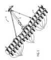
- row unit bouncemay be caused by the row unit 16 contacting a trench, uneven terrain, plant residue, rocks, or other obstructions, thereby inducing the metering systems to vary the rate at which seeds are deposited into the soil.
- bouncemay be defined as linear movement, angular movement, linear velocity, angular velocity, linear acceleration, angular acceleration, and/or higher order derivatives of translation and/or rotation of the row unit 16 .
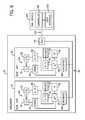
- the bounce sensormay be any suitable device configured to measure linear velocity, angular velocity, linear acceleration, angular acceleration, force, moment, or other parameters indicative of row unit bounce.
- a networked sensor interface 88may then receive the signal from the processor 80 , and broadcast the signal across a bus. While an optical seed sensor is described above, it should be appreciated that alternative embodiments may include other seed sensors configured to detect a flow of seeds through the seed tube 42 .
- the bounce sensor 90shares common circuitry with the optical seed sensor 60 in the present embodiment, in alternative embodiments, the bounce sensor 90 may share common circuitry with other electronic networks within the implement 10 . In yet further embodiments, the bounce sensor 90 may be coupled to other areas of the implement 10 , such as the tool bar 14 , to measure bounce of the implement 10 . In such embodiments, the bounce sensor 90 may still utilize a common network (e.g., networked sensor interface 88 , first bus 96 , and/or second bus 102 ) with the seed sensors 60 .
- a common networke.g., networked sensor interface 88 , first bus 96 , and/or second bus 102
Landscapes
- Life Sciences & Earth Sciences (AREA)
- Soil Sciences (AREA)
- Environmental Sciences (AREA)
- Sowing (AREA)
- Pretreatment Of Seeds And Plants (AREA)
Abstract
Description
Claims (20)
Priority Applications (3)
| Application Number | Priority Date | Filing Date | Title |
|---|---|---|---|
| US12/693,671US8448587B2 (en) | 2010-01-26 | 2010-01-26 | Row unit bounce monitoring system |
| CA2710692ACA2710692C (en) | 2010-01-26 | 2010-07-21 | Row unit bounce monitoring system |
| UAA201100840AUA106207C2 (en) | 2010-01-26 | 2011-01-25 | System to monitor jumping of sowing sections (variants) |
Applications Claiming Priority (1)
| Application Number | Priority Date | Filing Date | Title |
|---|---|---|---|
| US12/693,671US8448587B2 (en) | 2010-01-26 | 2010-01-26 | Row unit bounce monitoring system |
Publications (2)
| Publication Number | Publication Date |
|---|---|
| US20110184551A1 US20110184551A1 (en) | 2011-07-28 |
| US8448587B2true US8448587B2 (en) | 2013-05-28 |
Family
ID=44309568
Family Applications (1)
| Application Number | Title | Priority Date | Filing Date |
|---|---|---|---|
| US12/693,671Expired - Fee RelatedUS8448587B2 (en) | 2010-01-26 | 2010-01-26 | Row unit bounce monitoring system |
Country Status (3)
| Country | Link |
|---|---|
| US (1) | US8448587B2 (en) |
| CA (1) | CA2710692C (en) |
| UA (1) | UA106207C2 (en) |
Cited By (27)
| Publication number | Priority date | Publication date | Assignee | Title |
|---|---|---|---|---|
| US20130206431A1 (en)* | 2012-02-14 | 2013-08-15 | Brian Freed | Furrow closing assembly and method |
| US20140224513A1 (en)* | 2013-02-12 | 2014-08-14 | Yetter Manufacturing Company | Row treating unit for agriculture implement |
| US20160037704A1 (en)* | 2014-08-07 | 2016-02-11 | Cnh Industrial America Llc | Closing system for an agricultural implement |
| US9883626B2 (en)* | 2015-10-02 | 2018-02-06 | Deere & Company | Controlling an agricultural vehicle based on sensed inputs |
| US10750662B2 (en) | 2018-06-01 | 2020-08-25 | Deere & Company | Seed sensor |
| US10820468B2 (en) | 2018-09-19 | 2020-11-03 | Cnh Industrial America Llc | System and method for determining soil roughness of a field across which an agricultural implement is being moved based on ground engaging tool acceleration |
| US20210059108A1 (en)* | 2019-08-26 | 2021-03-04 | Cnh Industrial America Llc | Particle delivery assembly of an agricultural row unit |
| US11039565B2 (en) | 2019-04-25 | 2021-06-22 | Cnh Industrial America Llc | System and method for controlling the operation of rotating ground-engaging components of an agricultural implement based on the rotational speeds of such components |
| US11083125B2 (en)* | 2018-12-14 | 2021-08-10 | Cnh Industrial Canada, Ltd. | System and method for determining field characteristics based on ground engaging tool loads |
| US11191204B2 (en) | 2019-02-18 | 2021-12-07 | Cnh Industrial Canada, Ltd. | System and method for monitoring soil conditions within a field |
| US11215601B2 (en)* | 2018-10-25 | 2022-01-04 | Cnh Industrial Canada, Ltd. | System for monitoring soil conditions based on acoustic data and associated methods for adjusting operating parameters of a seed-planting implement based on monitored soil conditions |
| US11483963B2 (en) | 2019-12-24 | 2022-11-01 | Cnh Industrial America Llc | Particle delivery system of an agricultural row unit |
| US11490558B2 (en) | 2019-12-24 | 2022-11-08 | Cnh Industrial America Llc | Particle delivery system of an agricultural row unit |
| US11516958B2 (en) | 2019-12-24 | 2022-12-06 | Cnh Industrial America Llc | Particle delivery system of an agricultural row unit |
| US11523556B2 (en) | 2019-12-24 | 2022-12-13 | Cnh Industrial America Llc | Particle delivery system of an agricultural row unit |
| US11523555B2 (en) | 2019-12-24 | 2022-12-13 | Cnh Industrial America Llc | Particle delivery system of an agricultural row unit |
| US11553639B2 (en) | 2019-12-24 | 2023-01-17 | Cnh Industrial America Llc | Particle delivery system of an agricultural row unit |
| US11553638B2 (en) | 2019-12-24 | 2023-01-17 | Cnh Industrial America Llc | Particle delivery system of an agricultural row unit |
| US11564346B2 (en) | 2019-12-24 | 2023-01-31 | Cnh Industrial America Llc | Particle delivery system of an agricultural row unit |
| US11564344B2 (en) | 2019-12-24 | 2023-01-31 | Cnh Industrial America Llc | Particle delivery system of an agricultural row unit |
| US11582899B2 (en) | 2019-12-24 | 2023-02-21 | Cnh Industrial America Llc | Particle delivery system of an agricultural row unit |
| US11589494B2 (en) | 2019-11-06 | 2023-02-28 | Cnh Industrial Canada, Ltd. | System and method for managing material accumulation relative to ground engaging tools of an agricultural implement |
| US11589500B2 (en) | 2019-12-24 | 2023-02-28 | Cnh Industrial America Llc | Particle delivery system of an agricultural row unit |
| US11596095B2 (en) | 2019-12-24 | 2023-03-07 | Cnh Industrial America Llc | Particle delivery system of an agricultural row unit |
| US11839171B2 (en) | 2016-05-13 | 2023-12-12 | Precision Planting Llc | Seed trench depth detection systems |
| US12007222B2 (en) | 2019-08-13 | 2024-06-11 | Cnh Industrial Canada, Ltd. | System and method for determining field surface conditions using vision-based data and data from a secondary source |
| US12268115B2 (en) | 2020-02-07 | 2025-04-08 | Ag Leader Technology | Planter obstruction monitoring and associated devices and methods |
Families Citing this family (23)
| Publication number | Priority date | Publication date | Assignee | Title |
|---|---|---|---|---|
| US9743574B1 (en)* | 2007-10-24 | 2017-08-29 | Veris Technologies, Inc. | Mobile soil optical mapping system |
| US9320190B2 (en)* | 2011-06-03 | 2016-04-26 | Precision Planting Llc | Agricultural toolbar apparatus, systems and methods |
| US20150181799A1 (en)* | 2012-07-26 | 2015-07-02 | One Pass Implements Inc. | Ground opener assembly with dual gauge control |
| BR112015009089B1 (en) | 2012-10-24 | 2020-02-04 | Prec Planting Llc | agricultural line unit |
| US9664249B2 (en) | 2013-01-11 | 2017-05-30 | Cnh Industrial Canada, Ltd. | System and method of tractor control based on agricultural implement performance |
| US11231305B2 (en)* | 2013-09-26 | 2022-01-25 | Amvac Chemical Corporation | Flow sensor apparatus for monitoring a directed stream of an agricultural product |
| US10352743B1 (en)* | 2013-09-26 | 2019-07-16 | Sensors That Count, L.L.C. | Flow sensor based on electrical capacity |
| US9497900B2 (en)* | 2013-09-19 | 2016-11-22 | Agco Corporation | Planter with post seed tube mounted row cleaner and depth control tool |
| US9826677B2 (en)* | 2014-12-16 | 2017-11-28 | Cnh Industrial Canada, Ltd. | Seed implement incorporating a down pressure sensing and adjustment system |
| US10194579B2 (en)* | 2015-01-29 | 2019-02-05 | Cnh Industrial Canada, Ltd. | Sectional control calibration system and method |
| DE102015119070A1 (en)* | 2015-11-06 | 2017-05-11 | Amazonen-Werke H. Dreyer Gmbh & Co. Kg | Precision seed drill and method for operating a precision seed drill |
| US9936631B1 (en)* | 2016-09-30 | 2018-04-10 | Deere & Company | Device and method for detecting and reporting seed placement |
| DE102017204433A1 (en)* | 2017-03-16 | 2018-09-20 | Zf Friedrichshafen Ag | A method of operating a system of an agricultural work vehicle and at least one work implement disposed thereon |
| US11064646B2 (en)* | 2017-11-13 | 2021-07-20 | Cnh Industrial America Llc | System for treatment of an agricultural field with real time sensing of soil variability and/or clod stability |
| BR102017027139B1 (en)* | 2017-12-15 | 2023-03-21 | José Roberto do Amaral Assy | SENSING SYSTEM FOR AGRICULTURAL IMPLEMENT AND ROTATION SENSING METHOD APPLIED IN AGRICULTURAL IMPLEMENT |
| CN108811575B (en)* | 2018-06-27 | 2021-05-11 | 杭州益壤环境科技集团有限公司 | Agricultural equipment for agricultural soil improvement with automatically, spout medicine function |
| AU2019324566B2 (en)* | 2018-08-23 | 2024-07-11 | Precison Planting Llc | Expandable network architecture for communications between machines and implements |
| CN109220089B (en)* | 2018-10-25 | 2021-09-03 | 山东省计算中心(国家超级计算济南中心) | Cell seeding path alignment method based on Beidou satellite positioning |
| US11849659B2 (en) | 2018-11-20 | 2023-12-26 | Cnh Industrial America Llc | Draft load control system for an agricultural implement |
| CN109601077A (en)* | 2018-12-24 | 2019-04-12 | 山东省农业技术推广总站 | A kind of Wheat wide seeding machinery device with anti-blockage function at hopper blanking |
| CA3146855A1 (en)* | 2019-08-26 | 2021-03-04 | Brian John Anderson | Particle delivery assembly of an agricultural row unit |
| US20240180056A1 (en)* | 2022-12-01 | 2024-06-06 | Cnh Industrial America Llc | Agricultural system and method for detecting wing hop of an agricultural implement |
| CN117044444B (en)* | 2023-10-10 | 2023-12-22 | 安徽省农业科学院农业工程研究所 | Sweet potato seedling rotary tillage fertilization watering tectorial membrane all-in-one |
Citations (27)
| Publication number | Priority date | Publication date | Assignee | Title |
|---|---|---|---|---|
| US5075855A (en) | 1984-01-20 | 1991-12-24 | Nissan Motor Company, Limited | Automotive suspension control system with road-condition-dependent damping characteristics |
| US5143159A (en)* | 1991-06-03 | 1992-09-01 | Ford New Holland, Inc. | Draft control system with dual mode draft sensitivity |
| US5199000A (en)* | 1990-03-27 | 1993-03-30 | Nec Corporation | Semiconductor memory circuit having switched voltage supply for data bus lines |
| US5243512A (en) | 1991-05-20 | 1993-09-07 | Westinghouse Electric Corp. | Method and apparatus for minimizing vibration |
| US5383133A (en) | 1991-11-02 | 1995-01-17 | Westland Helicopters Limited | Integrated vibration reducing and health monitoring system for a helicopter |
| US5430432A (en) | 1992-12-14 | 1995-07-04 | Camhi; Elie | Automotive warning and recording system |
| US5487006A (en) | 1988-11-14 | 1996-01-23 | Atsugi Unisia Corporation | System for detecting road roughness for suspension control and automotive suspension control system utilizing thus detected road roughness as control parameter |
| US5893892A (en) | 1994-12-29 | 1999-04-13 | Dana Corporation | Vibration sensing and diagnostic system for vehicle drive train components |
| US5956255A (en)* | 1997-09-23 | 1999-09-21 | Case Corporation | Seed planter performance monitor |
| US5955942A (en) | 1995-11-28 | 1999-09-21 | Slifkin; Timothy P. | Methods and means for monitoring events in vehicles |
| US6196327B1 (en)* | 1999-04-01 | 2001-03-06 | Case Corporation | EDC draft force based ride controller |
| US6199000B1 (en) | 1998-07-15 | 2001-03-06 | Trimble Navigation Limited | Methods and apparatus for precision agriculture operations utilizing real time kinematic global positioning system systems |
| US6386128B1 (en)* | 2001-07-30 | 2002-05-14 | Bechtel Bwxt Idaho. Llc | Methods and systems for seed planting management and control |
| US20040122580A1 (en) | 2002-12-23 | 2004-06-24 | Sorrells Giles K. | Method and apparatus for determining road conditions |
| US6778894B2 (en) | 2001-01-08 | 2004-08-17 | Deere & Company | Monitoring device for a working vehicle |
| US20040243351A1 (en) | 2001-10-27 | 2004-12-02 | Vetronix Corporation | Noise, vibration and harshness analyzer |
| US6885968B2 (en) | 2000-05-08 | 2005-04-26 | Automotive Technologies International, Inc. | Vehicular exterior identification and monitoring system-agricultural product distribution |
| US6898501B2 (en) | 1999-07-15 | 2005-05-24 | Cnh America Llc | Apparatus for facilitating reduction of vibration in a work vehicle having an active CAB suspension system |
| US6941225B2 (en) | 2001-06-29 | 2005-09-06 | The Regents Of The University Of California | Method and apparatus for ultra precise GPS-based mapping of seeds or vegetation during planting |
| US7013832B2 (en) | 2000-04-28 | 2006-03-21 | Bae Systems Plc | Arrangement for damping of structural resonance |
| US7027953B2 (en) | 2002-12-30 | 2006-04-11 | Rsl Electronics Ltd. | Method and system for diagnostics and prognostics of a mechanical system |
| US7168324B2 (en) | 2002-08-12 | 2007-01-30 | Shinkawa Sensor Technology, Inc. | Vibration information transmission apparatus and vibration monitoring/analyzing system |
| US20080306706A1 (en) | 2007-06-07 | 2008-12-11 | Nenad Markovic | Accelerometer System |
| US7467034B2 (en) | 2002-11-04 | 2008-12-16 | Automotive Technologies International, Inc. | Tire monitoring techniques |
| US20090164060A1 (en) | 2007-02-19 | 2009-06-25 | Solidica, Inc. | Vehicle instability detection and prevention system |
| US7552577B2 (en)* | 2005-09-29 | 2009-06-30 | Cnh America Llc | Header flotation calibration system |
| US8078367B2 (en)* | 2007-01-08 | 2011-12-13 | Precision Planting, Inc. | Planter monitor system and method |
- 2010
- 2010-01-26USUS12/693,671patent/US8448587B2/ennot_activeExpired - Fee Related
- 2010-07-21CACA2710692Apatent/CA2710692C/enactiveActive
- 2011
- 2011-01-25UAUAA201100840Apatent/UA106207C2/enunknown
Patent Citations (27)
| Publication number | Priority date | Publication date | Assignee | Title |
|---|---|---|---|---|
| US5075855A (en) | 1984-01-20 | 1991-12-24 | Nissan Motor Company, Limited | Automotive suspension control system with road-condition-dependent damping characteristics |
| US5487006A (en) | 1988-11-14 | 1996-01-23 | Atsugi Unisia Corporation | System for detecting road roughness for suspension control and automotive suspension control system utilizing thus detected road roughness as control parameter |
| US5199000A (en)* | 1990-03-27 | 1993-03-30 | Nec Corporation | Semiconductor memory circuit having switched voltage supply for data bus lines |
| US5243512A (en) | 1991-05-20 | 1993-09-07 | Westinghouse Electric Corp. | Method and apparatus for minimizing vibration |
| US5143159A (en)* | 1991-06-03 | 1992-09-01 | Ford New Holland, Inc. | Draft control system with dual mode draft sensitivity |
| US5383133A (en) | 1991-11-02 | 1995-01-17 | Westland Helicopters Limited | Integrated vibration reducing and health monitoring system for a helicopter |
| US5430432A (en) | 1992-12-14 | 1995-07-04 | Camhi; Elie | Automotive warning and recording system |
| US5893892A (en) | 1994-12-29 | 1999-04-13 | Dana Corporation | Vibration sensing and diagnostic system for vehicle drive train components |
| US5955942A (en) | 1995-11-28 | 1999-09-21 | Slifkin; Timothy P. | Methods and means for monitoring events in vehicles |
| US5956255A (en)* | 1997-09-23 | 1999-09-21 | Case Corporation | Seed planter performance monitor |
| US6199000B1 (en) | 1998-07-15 | 2001-03-06 | Trimble Navigation Limited | Methods and apparatus for precision agriculture operations utilizing real time kinematic global positioning system systems |
| US6196327B1 (en)* | 1999-04-01 | 2001-03-06 | Case Corporation | EDC draft force based ride controller |
| US6898501B2 (en) | 1999-07-15 | 2005-05-24 | Cnh America Llc | Apparatus for facilitating reduction of vibration in a work vehicle having an active CAB suspension system |
| US7013832B2 (en) | 2000-04-28 | 2006-03-21 | Bae Systems Plc | Arrangement for damping of structural resonance |
| US6885968B2 (en) | 2000-05-08 | 2005-04-26 | Automotive Technologies International, Inc. | Vehicular exterior identification and monitoring system-agricultural product distribution |
| US6778894B2 (en) | 2001-01-08 | 2004-08-17 | Deere & Company | Monitoring device for a working vehicle |
| US6941225B2 (en) | 2001-06-29 | 2005-09-06 | The Regents Of The University Of California | Method and apparatus for ultra precise GPS-based mapping of seeds or vegetation during planting |
| US6386128B1 (en)* | 2001-07-30 | 2002-05-14 | Bechtel Bwxt Idaho. Llc | Methods and systems for seed planting management and control |
| US20040243351A1 (en) | 2001-10-27 | 2004-12-02 | Vetronix Corporation | Noise, vibration and harshness analyzer |
| US7168324B2 (en) | 2002-08-12 | 2007-01-30 | Shinkawa Sensor Technology, Inc. | Vibration information transmission apparatus and vibration monitoring/analyzing system |
| US7467034B2 (en) | 2002-11-04 | 2008-12-16 | Automotive Technologies International, Inc. | Tire monitoring techniques |
| US20040122580A1 (en) | 2002-12-23 | 2004-06-24 | Sorrells Giles K. | Method and apparatus for determining road conditions |
| US7027953B2 (en) | 2002-12-30 | 2006-04-11 | Rsl Electronics Ltd. | Method and system for diagnostics and prognostics of a mechanical system |
| US7552577B2 (en)* | 2005-09-29 | 2009-06-30 | Cnh America Llc | Header flotation calibration system |
| US8078367B2 (en)* | 2007-01-08 | 2011-12-13 | Precision Planting, Inc. | Planter monitor system and method |
| US20090164060A1 (en) | 2007-02-19 | 2009-06-25 | Solidica, Inc. | Vehicle instability detection and prevention system |
| US20080306706A1 (en) | 2007-06-07 | 2008-12-11 | Nenad Markovic | Accelerometer System |
Cited By (30)
| Publication number | Priority date | Publication date | Assignee | Title |
|---|---|---|---|---|
| US20130206431A1 (en)* | 2012-02-14 | 2013-08-15 | Brian Freed | Furrow closing assembly and method |
| US8939095B2 (en)* | 2012-02-14 | 2015-01-27 | Brian Freed | Furrow closing assembly and method |
| US20140224513A1 (en)* | 2013-02-12 | 2014-08-14 | Yetter Manufacturing Company | Row treating unit for agriculture implement |
| US9148989B2 (en)* | 2013-02-12 | 2015-10-06 | L & B Manufacturing, Inc. | Row treating unit for agriculture implement |
| US20160037704A1 (en)* | 2014-08-07 | 2016-02-11 | Cnh Industrial America Llc | Closing system for an agricultural implement |
| US9750176B2 (en)* | 2014-08-07 | 2017-09-05 | Cnh Industrial America Llc | Closing system for an agricultural implement |
| US9883626B2 (en)* | 2015-10-02 | 2018-02-06 | Deere & Company | Controlling an agricultural vehicle based on sensed inputs |
| US11839171B2 (en) | 2016-05-13 | 2023-12-12 | Precision Planting Llc | Seed trench depth detection systems |
| US10750662B2 (en) | 2018-06-01 | 2020-08-25 | Deere & Company | Seed sensor |
| US10820468B2 (en) | 2018-09-19 | 2020-11-03 | Cnh Industrial America Llc | System and method for determining soil roughness of a field across which an agricultural implement is being moved based on ground engaging tool acceleration |
| US11215601B2 (en)* | 2018-10-25 | 2022-01-04 | Cnh Industrial Canada, Ltd. | System for monitoring soil conditions based on acoustic data and associated methods for adjusting operating parameters of a seed-planting implement based on monitored soil conditions |
| US11083125B2 (en)* | 2018-12-14 | 2021-08-10 | Cnh Industrial Canada, Ltd. | System and method for determining field characteristics based on ground engaging tool loads |
| US11191204B2 (en) | 2019-02-18 | 2021-12-07 | Cnh Industrial Canada, Ltd. | System and method for monitoring soil conditions within a field |
| US11039565B2 (en) | 2019-04-25 | 2021-06-22 | Cnh Industrial America Llc | System and method for controlling the operation of rotating ground-engaging components of an agricultural implement based on the rotational speeds of such components |
| US12007222B2 (en) | 2019-08-13 | 2024-06-11 | Cnh Industrial Canada, Ltd. | System and method for determining field surface conditions using vision-based data and data from a secondary source |
| US20210059108A1 (en)* | 2019-08-26 | 2021-03-04 | Cnh Industrial America Llc | Particle delivery assembly of an agricultural row unit |
| US11589494B2 (en) | 2019-11-06 | 2023-02-28 | Cnh Industrial Canada, Ltd. | System and method for managing material accumulation relative to ground engaging tools of an agricultural implement |
| US11483963B2 (en) | 2019-12-24 | 2022-11-01 | Cnh Industrial America Llc | Particle delivery system of an agricultural row unit |
| US11523555B2 (en) | 2019-12-24 | 2022-12-13 | Cnh Industrial America Llc | Particle delivery system of an agricultural row unit |
| US11553639B2 (en) | 2019-12-24 | 2023-01-17 | Cnh Industrial America Llc | Particle delivery system of an agricultural row unit |
| US11553638B2 (en) | 2019-12-24 | 2023-01-17 | Cnh Industrial America Llc | Particle delivery system of an agricultural row unit |
| US11564346B2 (en) | 2019-12-24 | 2023-01-31 | Cnh Industrial America Llc | Particle delivery system of an agricultural row unit |
| US11564344B2 (en) | 2019-12-24 | 2023-01-31 | Cnh Industrial America Llc | Particle delivery system of an agricultural row unit |
| US11582899B2 (en) | 2019-12-24 | 2023-02-21 | Cnh Industrial America Llc | Particle delivery system of an agricultural row unit |
| US11523556B2 (en) | 2019-12-24 | 2022-12-13 | Cnh Industrial America Llc | Particle delivery system of an agricultural row unit |
| US11589500B2 (en) | 2019-12-24 | 2023-02-28 | Cnh Industrial America Llc | Particle delivery system of an agricultural row unit |
| US11596095B2 (en) | 2019-12-24 | 2023-03-07 | Cnh Industrial America Llc | Particle delivery system of an agricultural row unit |
| US11516958B2 (en) | 2019-12-24 | 2022-12-06 | Cnh Industrial America Llc | Particle delivery system of an agricultural row unit |
| US11490558B2 (en) | 2019-12-24 | 2022-11-08 | Cnh Industrial America Llc | Particle delivery system of an agricultural row unit |
| US12268115B2 (en) | 2020-02-07 | 2025-04-08 | Ag Leader Technology | Planter obstruction monitoring and associated devices and methods |
Also Published As
| Publication number | Publication date |
|---|---|
| UA106207C2 (en) | 2014-08-11 |
| US20110184551A1 (en) | 2011-07-28 |
| CA2710692C (en) | 2015-12-01 |
| CA2710692A1 (en) | 2011-07-26 |
Similar Documents
| Publication | Publication Date | Title |
|---|---|---|
| US8448587B2 (en) | Row unit bounce monitoring system | |
| CA2879731C (en) | Systems, methods and apparatus for multi-row agricultural implement control and monitoring | |
| US10772256B2 (en) | Systems, methods, and apparatus for multi-row agricultural implement control and monitoring | |
| EP3831179B1 (en) | Agricultural trench depth sensing system | |
| EP3295224B1 (en) | Work layer imaging and analysis for implement monitoring, control and operator feedback | |
| US20170339824A1 (en) | Agricultural devices, systems, and methods for determining soil and seed characteristics and analyzing the same | |
| MX2011005153A (en) | Seed sensor system and method for improved seed count and seed spacing. | |
| EP2701483A1 (en) | Agricultural devices, systems, and methods for determining soil and seed characteristics and analyzing the same | |
| CA2719508A1 (en) | Row unit wheel turning monitor for an agricultural machine | |
| MX2012009151A (en) | Seed sensor system and method for improved seed count and seed spacing. | |
| US20220373317A1 (en) | Agricultural trench depth sensing systems, methods, and apparatus | |
| US20200232792A1 (en) | Agricultural trench depth sensing systems, methods, and apparatus |
Legal Events
| Date | Code | Title | Description |
|---|---|---|---|
| AS | Assignment | Owner name:CNH CANADA, LTD, CANADA Free format text:ASSIGNMENT OF ASSIGNORS INTEREST;ASSIGNOR:KOWALCHUK, TREVOR;REEL/FRAME:023847/0531 Effective date:20100126 | |
| STCF | Information on status: patent grant | Free format text:PATENTED CASE | |
| AS | Assignment | Owner name:CNH INDUSTRIAL CANADA, LTD., CANADA Free format text:CHANGE OF NAME;ASSIGNOR:CNH CANADA, LTD.;REEL/FRAME:034030/0516 Effective date:20140301 | |
| FPAY | Fee payment | Year of fee payment:4 | |
| MAFP | Maintenance fee payment | Free format text:PAYMENT OF MAINTENANCE FEE, 8TH YEAR, LARGE ENTITY (ORIGINAL EVENT CODE: M1552); ENTITY STATUS OF PATENT OWNER: LARGE ENTITY Year of fee payment:8 | |
| FEPP | Fee payment procedure | Free format text:MAINTENANCE FEE REMINDER MAILED (ORIGINAL EVENT CODE: REM.); ENTITY STATUS OF PATENT OWNER: LARGE ENTITY | |
| LAPS | Lapse for failure to pay maintenance fees | Free format text:PATENT EXPIRED FOR FAILURE TO PAY MAINTENANCE FEES (ORIGINAL EVENT CODE: EXP.); ENTITY STATUS OF PATENT OWNER: LARGE ENTITY | |
| STCH | Information on status: patent discontinuation | Free format text:PATENT EXPIRED DUE TO NONPAYMENT OF MAINTENANCE FEES UNDER 37 CFR 1.362 | |
| FP | Lapsed due to failure to pay maintenance fee | Effective date:20250528 |