US8448544B2 - Induction hardened blade - Google Patents
Induction hardened bladeDownload PDFInfo
- Publication number
- US8448544B2 US8448544B2US13/456,075US201213456075AUS8448544B2US 8448544 B2US8448544 B2US 8448544B2US 201213456075 AUS201213456075 AUS 201213456075AUS 8448544 B2US8448544 B2US 8448544B2
- Authority
- US
- United States
- Prior art keywords
- cutting edge
- steel material
- edge portion
- strip steel
- strip
- Prior art date
- Legal status (The legal status is an assumption and is not a legal conclusion. Google has not performed a legal analysis and makes no representation as to the accuracy of the status listed.)
- Expired - Lifetime
Links
Images


Classifications
- B—PERFORMING OPERATIONS; TRANSPORTING
- B26—HAND CUTTING TOOLS; CUTTING; SEVERING
- B26B—HAND-HELD CUTTING TOOLS NOT OTHERWISE PROVIDED FOR
- B26B9/00—Blades for hand knives
- B—PERFORMING OPERATIONS; TRANSPORTING
- B26—HAND CUTTING TOOLS; CUTTING; SEVERING
- B26B—HAND-HELD CUTTING TOOLS NOT OTHERWISE PROVIDED FOR
- B26B21/00—Razors of the open or knife type; Safety razors or other shaving implements of the planing type; Hair-trimming devices involving a razor-blade; Equipment therefor
- C—CHEMISTRY; METALLURGY
- C21—METALLURGY OF IRON
- C21D—MODIFYING THE PHYSICAL STRUCTURE OF FERROUS METALS; GENERAL DEVICES FOR HEAT TREATMENT OF FERROUS OR NON-FERROUS METALS OR ALLOYS; MAKING METAL MALLEABLE, e.g. BY DECARBURISATION OR TEMPERING
- C21D1/00—General methods or devices for heat treatment, e.g. annealing, hardening, quenching or tempering
- C21D1/04—General methods or devices for heat treatment, e.g. annealing, hardening, quenching or tempering with simultaneous application of supersonic waves, magnetic or electric fields
- C—CHEMISTRY; METALLURGY
- C21—METALLURGY OF IRON
- C21D—MODIFYING THE PHYSICAL STRUCTURE OF FERROUS METALS; GENERAL DEVICES FOR HEAT TREATMENT OF FERROUS OR NON-FERROUS METALS OR ALLOYS; MAKING METAL MALLEABLE, e.g. BY DECARBURISATION OR TEMPERING
- C21D1/00—General methods or devices for heat treatment, e.g. annealing, hardening, quenching or tempering
- C21D1/18—Hardening; Quenching with or without subsequent tempering
- C—CHEMISTRY; METALLURGY
- C21—METALLURGY OF IRON
- C21D—MODIFYING THE PHYSICAL STRUCTURE OF FERROUS METALS; GENERAL DEVICES FOR HEAT TREATMENT OF FERROUS OR NON-FERROUS METALS OR ALLOYS; MAKING METAL MALLEABLE, e.g. BY DECARBURISATION OR TEMPERING
- C21D1/00—General methods or devices for heat treatment, e.g. annealing, hardening, quenching or tempering
- C21D1/34—Methods of heating
- C21D1/42—Induction heating
- C—CHEMISTRY; METALLURGY
- C21—METALLURGY OF IRON
- C21D—MODIFYING THE PHYSICAL STRUCTURE OF FERROUS METALS; GENERAL DEVICES FOR HEAT TREATMENT OF FERROUS OR NON-FERROUS METALS OR ALLOYS; MAKING METAL MALLEABLE, e.g. BY DECARBURISATION OR TEMPERING
- C21D9/00—Heat treatment, e.g. annealing, hardening, quenching or tempering, adapted for particular articles; Furnaces therefor
- C21D9/18—Heat treatment, e.g. annealing, hardening, quenching or tempering, adapted for particular articles; Furnaces therefor for knives, scythes, scissors, or like hand cutting tools
- C—CHEMISTRY; METALLURGY
- C21—METALLURGY OF IRON
- C21D—MODIFYING THE PHYSICAL STRUCTURE OF FERROUS METALS; GENERAL DEVICES FOR HEAT TREATMENT OF FERROUS OR NON-FERROUS METALS OR ALLOYS; MAKING METAL MALLEABLE, e.g. BY DECARBURISATION OR TEMPERING
- C21D2221/00—Treating localised areas of an article
- C21D2221/02—Edge parts
Definitions
- the present inventionrelates to a method of manufacturing a blade.
- the manufacture of bladesinvolves a sequence of manufacturing processes each of which is used to achieve a certain characteristic of the blade.
- the strip of blade materialmay be provided in a coil form.
- the strip of blade stockis delivered to a punch press were a plurality of openings are stamped into the strip to define attach points employed to retain the blade in a cartridge or onto a knife/razor handle, to partially shape the blade and remove excess material and also to optionally stamp a brand name, logo or other indication thereon.
- the stripis then scored to form a plurality of axially spaced score lines, wherein each score line corresponds to a side edge of a respective blade and defines a breaking line for later snapping or cutting the scored strip into a plurality of blades.
- the strip of blade stockis then generally fed through a heat treating oven to harden and temper the strip material.
- the heat treated stripis conventionally ground, honed and/or stropped to form the facets defining a straight cutting edge along one side of the strip.
- the stripis subsequently snapped along the length of the strip at each score line to break the strip along the score lines to produce a plurality of blades.
- An aspect of the present inventionis to provide a method of manufacturing a blade.
- the methodincludes heating and quenching a coil of strip steel material to harden the material, heating the strip steel material to temper the material, grinding a first angle along an edge of the material, and subsequent to the grinding, re-hardening the edge of the material.
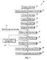
- FIG. 1is flow chart of a process of manufacturing a blade, according to an embodiment of present invention
- FIG. 2shows an example of a blade according to an embodiment of the present invention
- FIG. 3shows a cross section of an example of a ground edge of a steel strip, according to an embodiment of the present invention
- FIG. 4shows a cross section of an example of a ground edge of steel strip with a double angle edge, according to another embodiment of the present invention.
- FIG. 5shows a cross-section of a blade according to an embodiment of the present invention.
- FIG. 1is flow chart of a process of manufacturing a blade according to an embodiment of the present invention.
- a strip of steel blade stock materialfrom which a plurality of blades are produced, is provided at step 20 .
- the steelis provided in a coil form, for example, to render the strip more compact to facilitate handling.
- the steel materialis a high carbon steel such as, for example, steel grade C1095.
- the length of the strip in the coilcan be as long as 1 km or more.
- the stripmay also be provided in a multiple coils configuration, the multiple coils being welded end to end.
- the dimension of the stripcan be selected according to desired dimensions of the blade.
- the stripcan have a width of 19 mm and a thickness of 0.6 mm.
- the stripcan have other dimensions depending on the intended use of the blade that would be formed from the steel strip.
- the steel stripis provided with a maximum hardness of about 300 HV.
- the steel strip materialis delivered to a punch press where a plurality of openings are stamped into the strip to define attachment points employed to retain the blade in a cartridge or onto a blade carrier for utility knife.
- a brand name, logo or other indiciamay also be stamped thereon.
- FIG. 2shows an example of a knife blade according to an embodiment the present invention with its various geometrical dimensions.
- the knife blade 21includes openings 22 which can be employed to secure the blade 21 to utility knife blade carrier.
- the knife blade 21is also shown with a stamped “STANLEY” brand name 23 on a surface of the knife blade 21 .
- each score linecorresponds to a side edge 24 (shown in FIG. 2 ) of a respective blade and defines a breaking line for later snapping or cutting the scored strip into a plurality of blades.
- the side edges 24 of the blade shown in FIG. 2are configured to form a trapezoid blade. Other forms and shapes such as parallelogram blades, hook blades, etc. may also be obtained with a selection of an appropriate scoring configuration.
- the coil of pressed steel strip of blade stockis then fed at step 50 through a heat treatment line to harden the steel strip material.
- the steelis run off of the coil and passed through a hardening furnace which heats the steel to a temperature above a transition temperature.
- the transition temperatureis the temperature at which the structure of the steel changes from a body centred cubic structure, which is stable at room temperature, to a face centred cubic structure known as austenite (austenitic structure), which is stable at elevated temperatures, i.e. above the transition temperature.
- the transition temperaturevaries depending on the steel material used.
- the heating to harden the steel stripis performed at a temperature between about 800° C. and 900° C.
- the transition temperatureis approximately 820° C. (approximately 1508° F.).
- the heating to harden the steel stripis performed at a temperature above approximately 820° C.
- the length of the hardening/heating furnaceis approximately 26 feet (approximately 8 meters).
- the steel striptravels at a speed approximately between 16 and 22 feet per minute (approximately between 5 and 7 meters per minute).
- cracked ammoniamay be used to prevent oxidation and discoloration other gases may be used, such as but not limited to, “a scrubbed endothermic gas.”
- the heating of the steel strip to harden the steel stripis performed for a time period between about 75 and 105 seconds.
- the heat hardened steel stripis quenched.
- the hardened steel stripis passed between liquid cooled conductive blocks disposed above and below the steel strip to quench the steel strip.
- the heat hardened steel stripis passed through water-cooled brass blocks with carbide wear strips in contact with the steel strip to quench the steel. The brass blocks cool the steel strip from the hardening temperature, for example (approximately 820° C.), to ambient temperature (approximately 25° C.) at a speed above a critical rate of cooling.
- the critical rate of coolingis a rate at which the steel is cooled in order to ensure that the austenitic structure is transformed to martensitic structure.
- a martensitic structureis a body centred tetragonal structure. In the martensitic structure, the steel is highly stressed internally. This internal stress is responsible for the phenomenon known as hardening of the steel. After hardening, the hardness of the steel which was originally less than approximately 300 HV (before heat treatment) becomes approximately 850 HV (approximately 63 HRC).
- the quenching of the steel stripis performed for about 2 to 4 seconds.
- a gas or a liquidis used to quench the steel strip.
- the steel stripis then fed, at step 70 , into a tempering furnace which reduces the level of internal stress in the steel. As a result, some softening of the steel of the strip occurs with an associated increase in ductility.
- the tempering temperatureis approximately 200° C. (approximately 392° F.). This tempering process reduces the hardness of the steel to within a specified range of 750 to 820 HV.
- a length of the tempering furnaceis approximately 26 feet (approximately 8 meters).
- the striptravels in the tempering furnace at a speed between 16 and 22 feet per minute (approximately between 5 and 7 meters per minute).
- the steel stripmay be optionally quenched again in a controlled atmosphere to prevent discoloring of steel strip by oxidation.
- the quenching of the steel stripis performed for about 2 to 4seconds.
- a steel hardness value of approximately 750 to 820 HVWith a steel hardness value of approximately 750 to 820 HV, blades which are relatively sharp and having a relatively good longevity in service can be produced.
- the hardness valueis, however, a compromise.
- a higher hardness valuewould result in better grinding characteristics leading to a sharper blade and a longer lifespan of the blade.
- a higher hardness valuewould also result in a more brittle blade.
- a brittle blademay be susceptible to fracture if subjected to non-axial loads (for example, pressure on flat surfaces of the blade).
- a softer bladewould show improved ductility but would not perform well in service as the cutting edge would be blunted more quickly.
- the present inventionprovides a blade in which the body of the blade is soft enough to provide adequate ductility while providing the blade with an edge having a relatively higher hardness value to obtain better grinding characteristics of the edge. Providing an edge with a relatively higher hardness value permits a sharper edge to be ground, with increased lifespan.
- the steel stripis recoiled and is transferred to a grinding machine for grinding an edge of the strip.
- a relatively shallow anglesuch as between 10 to 32 degrees is ground onto the edge of the strip. This angle is ground on both sides of the blade, so that the blade is generally symmetrical relative to a longitudinal axis of the blade that bisects the edge, as can be appreciated from FIG. 3 .
- the ground angleis measured relative to the longitudinal axis as can also be appreciated from FIG. 3 .
- the angleis selected to be shallow to reduce the force that may be required to push the blade through the material it is cutting.
- FIG. 3shows a cross section of an example of a ground edge of a steel strip, according to an embodiment of the present invention. In this example, the angle of the ground edge 32 of the steel strip 31 is 22° ⁇ 2°.
- the edge of the steel stripmay be honed.
- the process of honingputs a second, less acute, angle, such as between 26 to 36 degrees, on top of the ground edge. This deeper honed angle gives a stronger edge than the more shallow ground angle and allows to extend the life span of the cutting edge. As a result the strip has an edge with a double angle.
- FIG. 4shows a cross section of another embodiment of a blade according to the invention.
- the ground edge of a steel stripis ground so as to be provided with a double angled edge.
- a first, upper angle of the ground edge 33 of the steel strip 33is 14° ⁇ 2° and a second, lower honed angle of the edge 34 of the steel strip is 32° ⁇ 2°.
- the transition between the first angle and the second angleis labelled by character reference “T” in FIG. 4 .
- Stropping the edge of the steel strip, at step 100may be optionally added to the edge production sequence.
- soft wheels of leather or a synthetic compoundare used to remove any burrs that have been produced by the honing process. The softer the steel the more likely it is that burrs will form.
- the steel stripis moved at 32 feet per minute (approximately 10 meters per minute) throughout the grinding, the honing and the stropping operations. In another embodiment, the steel strip is moved at 82 feet per minute (approximately 25 meters per minute) throughout the grinding, the honing and the stropping operations.
- the edge of the steel stripis ground at a single angle between 10 and 32 degrees (for example, see the edge of the steel strip shown in FIG. 3 ).
- the edge of the stripmay not be stropped.
- the stropping processis used to remove any burrs that have been produced by the honing process. In this case, because the edge of the steel strip is ground and not honed, stropping may not be used.
- a re-hardening processis applied to the edge of the steel strip.
- an induction hardening processis applied to the edge of the steel strip.
- a generatorproduces a high frequency alternating current at a high voltage and low current.
- the high frequency alternating currentis passed through an inductor located in close proximity to the steel strip.
- the high frequency currentinduces heating in the steel strip.
- the temperaturecan be controlled by selection of the frequency of the current, by selection of the current intensity value, by selection of the geometry of the inductor, by varying the speed of travel of the strip relative to the inductor, and/or by selection of the position of the inductor relative to the workpiece, i.e. the steel strip.
- the inductoris selected to be approximately 8 mm ⁇ 8 mm ⁇ 8 mm and the steel strip is moved at a grinding speed of 25 meters per minute.
- the induction heatingis performed by applying an induction frequency between about 26 and 30 MHz.
- the induction hardening processre-heats the steel strip locally, at the cutting edge, to a temperature above the transition temperature of approximately between 800° C. and 900° C.
- the induction hardening processre-heats the steel strip locally, at the cutting edge, to a temperature above the transition temperature of approximately 820° C. (approximately 1508° F.).
- the cutting edgeis re-hardened by induction heating followed by rapid cooling at a rate above the critical rate to produce a hard, fully martensitic structure along the cutting edge.
- a rapid cooling of the cutting edgeis achieved by any or a combination of the following: conduction into the body of the blade, convection into the environment, and/or artificially accelerated cooling by an air blast or liquid quench.
- a relatively hard cutting edgefor example, approximately 0.1 to 1.0 mm deep, from the tip of the edge to the body of the steel strip
- the cutting edge of the steel stripis harder than the body of the steel strip.
- the induction hardening of the edge of the steel stripcan be carried out at any point during or after the grinding (step 80 ), honing (step 90 ) or stropping (step 100 ) operations, or in general before forming the individual blades, to produce a blade with an edge having improved hardness while the core or body of the blade is maintained relatively soft.
- the hardness of the body of the bladecan be adjusted at the tempering stage (step 70 ), by employing different hardening temperatures, to produce softer, more ductile and safer blades with a relatively high hardness cutting edge (for example, a hardness greater than 850 HV or 66 HRC can be obtained) to facilitate smoother grinding and extended service life of the blade.
- the processed steel stripis snapped along the length of the steel strip at each score line to break the steel strip along the score lines to produce a plurality of blades, at step 120 .
- An example of an embodiment of a blade obtained according to the manufacturing process of the present inventionis shown with its various dimensions in FIG. 2 .
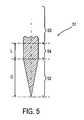
- FIG. 5shows a cross-section of a blade according to an embodiment of the present invention.
- both the conventional blade, manufactured according to a conventional process and the blade 51 manufactured according to the process of the present inventionare manufactured starting from a same bulk hardened steel strip material.
- the hardness of the bulk steel materialis approximately 62 HRC to 64 HRC throughout a cross-section of the steel strip.
- the hardness of the steel bladewhich was approximately 62 HRC to 64 HRC throughout a cross-section of the blade, is reduced at the cutting edge due to heating during grinding by typically 0.5 HRC to 1.0 HRC.
- the hardness of the blade manufactured according to a conventional processis between 62 and 63 HRC at the cutting edge and approximately 62 HRC to 64 HRC away from the cutting edge (i.e., towards the body or core of the blade).
- the structure of the steel of the bladeis a tempered martensite throughout the blade.
- a re-hardening, for example, an induction hardening, of the edge 52 of the blade 51is performed after grinding the edge 52 of the blade 51 .
- the induction hardening processhardens the edge 52 so as to offset any loss of hardness that may have occurred during grinding of the edge 52 .
- the hardness of the blade at the cutting edge 52is more than 64 HRC (for example, between 64 HRC and 65 HRC), i.e., greater than the hardness of the core of the blade (between 62 HRC and 64 HRC).
- the structure of the steel of the bladeis a tempered martensite in the body of the blade 53 and fine untempered martensite at the induction hardened edge 52 .
- the induction hardening of the edge 52 of the blade 51produces a re-hardened edge portion 52 with a depth D of approximately 0.5 mm, starting from the tip of the edge 52 towards the core of the blade 53 .
- the depth D of the edge portion 52can be reduced to 0.3 mm after honing.
- This edge portion 52is martensitic, more specifically fine martensitic.
- Behind the induction hardened portion 52there is a Heat Affected Zone (HAZ) 54 having a structure which is relatively softer compared to the induction hardened portion 52 or the core 53 of the blade 51 .
- the HAZ 54extends approximately a distance L of approximately 0.4 mm.
- the hardness of the steelmay drop as low as 5 0 HRC.
- the softer steel structure in the HAZ 54is due to this zone 54 either not having been reheated to above the transition temperature or not having cooled at above the critical rate. Behind the HAZ 54 there is the remaining portion of the blade (core of the blade) 53 . After reaching a minimum at the HAZ 54 , the hardness increases again until reaching the hardness of the initial bulk steel material (i.e., 62 HRC to 63 HRC) at about 0.5 mm from the cutting edge 52 .
Landscapes
- Chemical & Material Sciences (AREA)
- Engineering & Computer Science (AREA)
- Mechanical Engineering (AREA)
- Physics & Mathematics (AREA)
- Thermal Sciences (AREA)
- Crystallography & Structural Chemistry (AREA)
- Materials Engineering (AREA)
- Metallurgy (AREA)
- Organic Chemistry (AREA)
- Life Sciences & Earth Sciences (AREA)
- Forests & Forestry (AREA)
- Heat Treatment Of Articles (AREA)
Abstract
Description
Claims (24)
Priority Applications (1)
| Application Number | Priority Date | Filing Date | Title |
|---|---|---|---|
| US13/456,075US8448544B2 (en) | 2005-07-08 | 2012-04-25 | Induction hardened blade |
Applications Claiming Priority (2)
| Application Number | Priority Date | Filing Date | Title |
|---|---|---|---|
| US11/176,425US8322253B2 (en) | 2005-07-08 | 2005-07-08 | Method of manufacturing a utility knife blade having an induction hardened cutting edge |
| US13/456,075US8448544B2 (en) | 2005-07-08 | 2012-04-25 | Induction hardened blade |
Related Parent Applications (1)
| Application Number | Title | Priority Date | Filing Date |
|---|---|---|---|
| US11/176,425ContinuationUS8322253B2 (en) | 2005-07-08 | 2005-07-08 | Method of manufacturing a utility knife blade having an induction hardened cutting edge |
Publications (2)
| Publication Number | Publication Date |
|---|---|
| US20120205015A1 US20120205015A1 (en) | 2012-08-16 |
| US8448544B2true US8448544B2 (en) | 2013-05-28 |
Family
ID=35911500
Family Applications (3)
| Application Number | Title | Priority Date | Filing Date |
|---|---|---|---|
| US11/176,425Active2027-09-23US8322253B2 (en) | 2005-07-08 | 2005-07-08 | Method of manufacturing a utility knife blade having an induction hardened cutting edge |
| US12/068,427Expired - LifetimeUS8316550B2 (en) | 2005-07-08 | 2008-02-06 | Induction hardened blade |
| US13/456,075Expired - LifetimeUS8448544B2 (en) | 2005-07-08 | 2012-04-25 | Induction hardened blade |
Family Applications Before (2)
| Application Number | Title | Priority Date | Filing Date |
|---|---|---|---|
| US11/176,425Active2027-09-23US8322253B2 (en) | 2005-07-08 | 2005-07-08 | Method of manufacturing a utility knife blade having an induction hardened cutting edge |
| US12/068,427Expired - LifetimeUS8316550B2 (en) | 2005-07-08 | 2008-02-06 | Induction hardened blade |
Country Status (6)
| Country | Link |
|---|---|
| US (3) | US8322253B2 (en) |
| CN (2) | CN1891395B (en) |
| CA (1) | CA2532125C (en) |
| FR (1) | FR2888135B1 (en) |
| GB (1) | GB2434763B (en) |
| TW (1) | TWI353918B (en) |
Cited By (5)
| Publication number | Priority date | Publication date | Assignee | Title |
|---|---|---|---|---|
| US20100263491A1 (en)* | 2001-07-26 | 2010-10-21 | Korb William B | Method of Making a Composite Utility Blade |
| US20170217029A1 (en)* | 2016-02-03 | 2017-08-03 | KLEVER KUTTER LLC dba/Klever Innovations | Safety utility blades, assemblies and methods of manufacturing |
| US10350775B2 (en)* | 2013-04-19 | 2019-07-16 | Klever Kutter Llc | Safety utility blades, assemblies and methods of manufacturing |
| US20190329435A1 (en)* | 2018-04-27 | 2019-10-31 | Mathew J. Jacobs | Safety utility blades, assemblies and methods of manufacturing |
| US20220030766A1 (en)* | 2018-09-13 | 2022-02-03 | Husqvarna Ab | Cutting Blade for a Robotic Work Tool |
Families Citing this family (35)
| Publication number | Priority date | Publication date | Assignee | Title |
|---|---|---|---|---|
| US8322253B2 (en)* | 2005-07-08 | 2012-12-04 | Stanley Black & Decker, Inc. | Method of manufacturing a utility knife blade having an induction hardened cutting edge |
| PL2276591T3 (en)* | 2008-05-05 | 2013-11-29 | Eveready Battery Inc | Method of making a razor blade |
| US8505414B2 (en)* | 2008-06-23 | 2013-08-13 | Stanley Black & Decker, Inc. | Method of manufacturing a blade |
| US10442093B2 (en)* | 2009-11-18 | 2019-10-15 | Klever Kutter Llc | Safety utility blades, assemblies and methods of manufacturing |
| CN102791424B (en)* | 2010-03-12 | 2016-05-25 | 埃奇克拉夫特公司 | Knife Sharpeners for Asian and European/American Knives |
| US20120000074A1 (en)* | 2010-07-01 | 2012-01-05 | Pazosschroeder Marta | Erodible Label For Razor Cartridge |
| US9956696B2 (en)* | 2010-07-26 | 2018-05-01 | Start Food-Tech Nz Limited | Knife |
| US8769833B2 (en) | 2010-09-10 | 2014-07-08 | Stanley Black & Decker, Inc. | Utility knife blade |
| US20120144680A1 (en)* | 2010-12-10 | 2012-06-14 | Stanley Black & Decker, Inc. | Cutting blade and method of manufacturing the same |
| CN102166713A (en)* | 2010-12-29 | 2011-08-31 | 重庆文理学院 | Processing method of rectangular kitchen knife blank without providing with handle |
| US9102071B2 (en)* | 2011-01-06 | 2015-08-11 | Eveready Battery Company, Inc | Razor blade technology |
| PT2714327T (en)* | 2011-05-23 | 2019-10-09 | Rosjoh Pty Ltd | Improvements in knife sharpening methods |
| JP2014094163A (en)* | 2012-11-09 | 2014-05-22 | 3M Innovative Properties Co | Cutter blades |
| US9538704B2 (en) | 2013-02-15 | 2017-01-10 | Hrm Enterprises, Inc. | Horizontal rotary mower with thin replaceable blades |
| US9907226B2 (en) | 2013-02-15 | 2018-03-06 | Hrm Enterprises, Inc. | Cross flow horizontal rotary lawn mower with replaceable blade cartridges |
| US10375883B2 (en) | 2013-02-15 | 2019-08-13 | Hrm Enterprises, Inc. | Horizontal rotary trimmer with vented baffle |
| CN103806869A (en)* | 2014-02-28 | 2014-05-21 | 成都大漠石油机械有限公司 | Inner-oil-tube cleaning tool |
| CN107107362B (en) | 2014-12-22 | 2020-08-04 | 比克-维尔莱克 | razor blade |
| CN104480280B (en)* | 2014-12-22 | 2017-10-10 | 奥美森智能装备股份有限公司 | A kind of breaker bar |
| EP4541538A3 (en) | 2015-02-19 | 2025-08-20 | Stryker Corporation | Surgical saw and complementary saw blade, the blade including lock teeth formed out of material that deforms when the blade is secured to the saw |
| US11020108B2 (en) | 2015-03-02 | 2021-06-01 | Mound Laser & Photonics Center, Inc. | Needle with rounded edge |
| US11285631B2 (en) | 2015-03-02 | 2022-03-29 | Mound Laser & Photonics Center, Inc. | Chemically sharpening blades |
| US9844888B2 (en) | 2015-03-02 | 2017-12-19 | Hutchinson Technology Incorporated | Chemically sharpening blades |
| US10730193B2 (en)* | 2015-06-22 | 2020-08-04 | Kyocera Corporation | Cutter |
| CN105127705A (en)* | 2015-09-21 | 2015-12-09 | 安庆创跃电器有限公司 | Trimming blade forging technology |
| US11230025B2 (en)* | 2015-11-13 | 2022-01-25 | The Gillette Company Llc | Razor blade |
| CN105922295B (en)* | 2016-06-01 | 2017-10-31 | 山东大学 | The vertical orientated high-strength wearable cutter of primary hardening constituent fiber |
| US20180029241A1 (en)* | 2016-07-29 | 2018-02-01 | Liquidmetal Coatings, Llc | Method of forming cutting tools with amorphous alloys on an edge thereof |
| US11654588B2 (en) | 2016-08-15 | 2023-05-23 | The Gillette Company Llc | Razor blades |
| WO2018118560A1 (en)* | 2016-12-19 | 2018-06-28 | The Gillette Company Llc | Razor blades |
| CN109746845A (en)* | 2017-11-06 | 2019-05-14 | 杭州联和工具制造有限公司 | A hand tool and its manufacturing method |
| US20220331127A1 (en)* | 2019-08-06 | 2022-10-20 | Stefan Eggli | Bone plug compression instrument |
| CN113560961A (en)* | 2021-07-15 | 2021-10-29 | 马鞍山市恒利达机械刀片有限公司 | Processing technology of high-precision non-woven fabric upper cutter |
| EP4261295A1 (en)* | 2022-04-12 | 2023-10-18 | "Credo" Stahlwarenfabrik Gustav Kracht GmbH & Co. KG | Method for producing a blade |
| CN118895682B (en)* | 2024-06-26 | 2025-03-18 | 山东黑旋风锯业有限公司 | A pulp scraper and manufacturing method |
Citations (57)
| Publication number | Priority date | Publication date | Assignee | Title |
|---|---|---|---|---|
| GB1050520A (en) | 1900-01-01 | |||
| US972436A (en) | 1910-08-06 | 1910-10-11 | Osroe A Clark | Process of making blades with soft centers. |
| US1130650A (en) | 1914-05-15 | 1915-03-02 | John Whitaker | Process of hardening the cutting portions of cutting-tools |
| US1732244A (en) | 1928-03-29 | 1929-10-22 | Samuel I Salzman | Method of hardening steel |
| US2032963A (en) | 1934-09-29 | 1936-03-03 | Rockwell W S Co | Method of coloring and hardening steel |
| US2073502A (en) | 1936-04-08 | 1937-03-09 | Gillette Safety Razor Co | Safety razor blade and blade strip |
| US2093874A (en) | 1935-09-11 | 1937-09-21 | Gillette Safety Razor Co | Fine edged blade and method of making the same |
| US2131505A (en) | 1938-08-16 | 1938-09-27 | Henry M Garsson | Treating steel |
| US2408790A (en) | 1944-05-16 | 1946-10-08 | Edward L Mack | Razor blade and other cutting tools |
| GB645100A (en) | 1948-06-03 | 1950-10-25 | Gerhard Walter Seulen | Improvements in or relating to surface-hardened thin flat work-pieces and a process for producing them |
| US3411208A (en) | 1965-06-14 | 1968-11-19 | Sandvikens Jernverks Ab | Cutting strips, cutting die knives, cutting rules and the like |
| US3608877A (en) | 1970-11-09 | 1971-09-28 | United States Steel Corp | Apparatus for treating circular saw blades |
| US3923561A (en) | 1972-08-17 | 1975-12-02 | Toushichi Ishizawa | Method of heat treating saw |
| US3988955A (en) | 1972-12-14 | 1976-11-02 | Engel Niels N | Coated steel product and process of producing the same |
| US4103880A (en) | 1976-09-16 | 1978-08-01 | C. I. Hayes Inc. | Apparatus for heat treating drill blanks |
| FR2383235A1 (en) | 1977-03-10 | 1978-10-06 | Elphiac Ab | Continuous induction hardening and tempering of steel strip - via row of inductors and quenching sprays, esp. to mfr. saw blades |
| US4335630A (en) | 1980-09-02 | 1982-06-22 | Acu-Edge, Inc. | High-speed manufacturing system for saber sawblades and the like |
| US4383677A (en) | 1979-05-14 | 1983-05-17 | Deere & Company | Blade fabricating process |
| US4534827A (en) | 1983-08-26 | 1985-08-13 | Henderson Donald W | Cutting implement and method of making same |
| US4693157A (en) | 1980-09-16 | 1987-09-15 | Gottlieb Looser | Cutting device |
| US4720918A (en) | 1982-11-19 | 1988-01-26 | Curry Francis R | Razor blades |
| US4957421A (en) | 1983-10-03 | 1990-09-18 | Alloy Surfaces Company, Inc. | Metal treatment |
| US5048191A (en) | 1990-06-08 | 1991-09-17 | The Gillette Company | Razor blade technology |
| US5073212A (en) | 1989-12-29 | 1991-12-17 | Westinghouse Electric Corp. | Method of surface hardening of turbine blades and the like with high energy thermal pulses, and resulting product |
| US5077901A (en) | 1990-05-18 | 1992-01-07 | Warner Joseph A | Ceramic blades and production methodology therefor |
| US5210925A (en)* | 1992-02-21 | 1993-05-18 | Buck Knives, Inc. | Process for manufacturing a knife |
| US5295305A (en) | 1992-02-13 | 1994-03-22 | The Gillette Company | Razor blade technology |
| US5433801A (en) | 1990-11-10 | 1995-07-18 | Althaus; Wolfgang | Razor blade steel having high corrosion resistance, razor blades and a process for manufacturing razor blades |
| US5458025A (en) | 1994-03-17 | 1995-10-17 | The Gillette Company | Razor blade manufacture |
| US5724868A (en) | 1996-01-11 | 1998-03-10 | Buck Knives, Inc. | Method of making knife with cutting performance |
| US5987752A (en) | 1998-02-02 | 1999-11-23 | Swanstrom Tools Usa Inc. | Tool for farriers |
| US6293020B1 (en) | 1997-02-14 | 2001-09-25 | Nitinol Technologies, Inc. | Cutting instruments |
| US6335506B2 (en) | 1999-07-12 | 2002-01-01 | J. F. Helmold & Brothers, Inc. | Laser hardened steel cutting rule |
| US6389699B1 (en) | 1998-05-26 | 2002-05-21 | Globix Technologies, Inc. | Self sharpening blades and method for making same |
| US20020100522A1 (en) | 2000-12-01 | 2002-08-01 | Benton Rufus C. | Method and apparatus for bainite blades |
| US6443214B1 (en) | 1999-12-07 | 2002-09-03 | Honda Giken Kogyo Kabushiki Kaisha | Method for heat treating mold cast product |
| US20020142182A1 (en) | 2001-03-07 | 2002-10-03 | Atakan Peker | Sharp-edged cutting tools |
| US20020151393A1 (en) | 2001-04-16 | 2002-10-17 | Liechty Victory Jay | Cutting blade |
| US20030019111A1 (en) | 2001-07-26 | 2003-01-30 | Korb William B. | Composite utility knife blade, and method of making such a blade |
| JP2003147437A (en) | 2001-11-08 | 2003-05-21 | Daido Steel Co Ltd | How to harden the cutting edge |
| US6632302B2 (en) | 2000-07-28 | 2003-10-14 | Geoffrey Philip Fisher | Method and means for heat treating cutting tools |
| US20030213798A1 (en) | 2002-03-01 | 2003-11-20 | Saluja Navtej Singh | Inductive heating of semi-solid material |
| US20040031787A1 (en) | 2002-06-28 | 2004-02-19 | Forward Technology A Crest Group Company | Method and apparatus for induction hardening |
| US20040113461A1 (en) | 2001-11-27 | 2004-06-17 | Satoshi Shimizu | Press molding and its high frequency quenching method and its high frequency quenching system |
| US20040169099A1 (en) | 2001-07-04 | 2004-09-02 | Antti Tohkala | Method for increasing the shearing resistance in disk chipper knife mounting clamps and a disk chipper equipped with such knife mounting clamps |
| US20040187644A1 (en) | 2003-02-25 | 2004-09-30 | Eveready Battery Company, Inc. | Method for manufacturing a razor blade |
| US20040204726A1 (en) | 2003-03-17 | 2004-10-14 | Memx, Inc. | Separating a microkeratome blade from a wafer |
| US6813923B2 (en) | 2000-07-06 | 2004-11-09 | Trico Products Corporation | Method and apparatus for flexible manufacturing a discrete curved product from feed stock |
| US20040237722A1 (en) | 2001-06-25 | 2004-12-02 | Helmut Ponemayr | Strip-shaped cutting tools |
| US20040244539A1 (en) | 2001-07-26 | 2004-12-09 | Korb William B. | Composite utility blade, and method of making such a blade |
| US6866894B2 (en) | 2000-02-29 | 2005-03-15 | The Gillette Company | Razor blade technology |
| US6957598B2 (en) | 2000-07-18 | 2005-10-25 | The Gillette Company | Razor blade and method of manufacture |
| US7060367B2 (en) | 2000-06-05 | 2006-06-13 | Kai R&D Center Co., Ltd. | Cutting blade and method of producing the same |
| US20070006683A1 (en) | 2005-07-08 | 2007-01-11 | The Stanley Works | Induction hardened blade |
| US20070124939A1 (en) | 2003-06-26 | 2007-06-07 | Koninklijke Philips Electronics N.V. | Bent razor blades and manufacturing of such razor blades |
| US20070234577A1 (en) | 2006-04-10 | 2007-10-11 | William Masek | Cutting members for shaving razors |
| US20120144680A1 (en)* | 2010-12-10 | 2012-06-14 | Stanley Black & Decker, Inc. | Cutting blade and method of manufacturing the same |
Family Cites Families (5)
| Publication number | Priority date | Publication date | Assignee | Title |
|---|---|---|---|---|
| GB569229A (en)* | 1943-10-06 | 1945-05-14 | Norman Leslie Stephen Hay | Novel or improved safety razor |
| US3635811A (en)* | 1967-11-06 | 1972-01-18 | Warner Lambert Co | Method of applying a coating |
| US3761373A (en)* | 1971-07-09 | 1973-09-25 | Gillette Co | Process for producing an improved cutting tool |
| GB1598352A (en)* | 1977-11-26 | 1981-09-16 | Wilkinson Sword Ltd | Manufacture of razor blades |
| CN1059567A (en)* | 1990-08-27 | 1992-03-18 | 王美俊 | Bainite steel shearing-blade and thermal treatment process thereof |
- 2005
- 2005-07-08USUS11/176,425patent/US8322253B2/enactiveActive
- 2005-12-22TWTW094145840Apatent/TWI353918B/ennot_activeIP Right Cessation
- 2006
- 2006-01-05CACA2532125Apatent/CA2532125C/ennot_activeExpired - Fee Related
- 2006-01-06GBGB0600251Apatent/GB2434763B/enactiveActive
- 2006-02-14CNCN2006100044344Apatent/CN1891395B/ennot_activeExpired - Fee Related
- 2006-02-14CNCN201110176295.4Apatent/CN102248189B/ennot_activeExpired - Fee Related
- 2006-03-20FRFR0602419Apatent/FR2888135B1/ennot_activeExpired - Fee Related
- 2008
- 2008-02-06USUS12/068,427patent/US8316550B2/ennot_activeExpired - Lifetime
- 2012
- 2012-04-25USUS13/456,075patent/US8448544B2/ennot_activeExpired - Lifetime
Patent Citations (71)
| Publication number | Priority date | Publication date | Assignee | Title |
|---|---|---|---|---|
| GB1050520A (en) | 1900-01-01 | |||
| US972436A (en) | 1910-08-06 | 1910-10-11 | Osroe A Clark | Process of making blades with soft centers. |
| US1130650A (en) | 1914-05-15 | 1915-03-02 | John Whitaker | Process of hardening the cutting portions of cutting-tools |
| US1732244A (en) | 1928-03-29 | 1929-10-22 | Samuel I Salzman | Method of hardening steel |
| US2032963A (en) | 1934-09-29 | 1936-03-03 | Rockwell W S Co | Method of coloring and hardening steel |
| US2093874A (en) | 1935-09-11 | 1937-09-21 | Gillette Safety Razor Co | Fine edged blade and method of making the same |
| US2073502A (en) | 1936-04-08 | 1937-03-09 | Gillette Safety Razor Co | Safety razor blade and blade strip |
| US2131505A (en) | 1938-08-16 | 1938-09-27 | Henry M Garsson | Treating steel |
| US2408790A (en) | 1944-05-16 | 1946-10-08 | Edward L Mack | Razor blade and other cutting tools |
| GB645100A (en) | 1948-06-03 | 1950-10-25 | Gerhard Walter Seulen | Improvements in or relating to surface-hardened thin flat work-pieces and a process for producing them |
| US3411208A (en) | 1965-06-14 | 1968-11-19 | Sandvikens Jernverks Ab | Cutting strips, cutting die knives, cutting rules and the like |
| US3581604A (en) | 1965-06-14 | 1971-06-01 | Sandvik Steel Of Colorado Inc | Cutting strips, cutting die knives, cutting rules and the like |
| US3608877A (en) | 1970-11-09 | 1971-09-28 | United States Steel Corp | Apparatus for treating circular saw blades |
| US3923561A (en) | 1972-08-17 | 1975-12-02 | Toushichi Ishizawa | Method of heat treating saw |
| US3988955A (en) | 1972-12-14 | 1976-11-02 | Engel Niels N | Coated steel product and process of producing the same |
| US4103880A (en) | 1976-09-16 | 1978-08-01 | C. I. Hayes Inc. | Apparatus for heat treating drill blanks |
| FR2383235A1 (en) | 1977-03-10 | 1978-10-06 | Elphiac Ab | Continuous induction hardening and tempering of steel strip - via row of inductors and quenching sprays, esp. to mfr. saw blades |
| US4383677A (en) | 1979-05-14 | 1983-05-17 | Deere & Company | Blade fabricating process |
| US4335630A (en) | 1980-09-02 | 1982-06-22 | Acu-Edge, Inc. | High-speed manufacturing system for saber sawblades and the like |
| US4693157A (en) | 1980-09-16 | 1987-09-15 | Gottlieb Looser | Cutting device |
| US4720918A (en) | 1982-11-19 | 1988-01-26 | Curry Francis R | Razor blades |
| US4534827A (en) | 1983-08-26 | 1985-08-13 | Henderson Donald W | Cutting implement and method of making same |
| US4957421A (en) | 1983-10-03 | 1990-09-18 | Alloy Surfaces Company, Inc. | Metal treatment |
| US5073212A (en) | 1989-12-29 | 1991-12-17 | Westinghouse Electric Corp. | Method of surface hardening of turbine blades and the like with high energy thermal pulses, and resulting product |
| US5077901A (en) | 1990-05-18 | 1992-01-07 | Warner Joseph A | Ceramic blades and production methodology therefor |
| US5048191A (en) | 1990-06-08 | 1991-09-17 | The Gillette Company | Razor blade technology |
| US5433801A (en) | 1990-11-10 | 1995-07-18 | Althaus; Wolfgang | Razor blade steel having high corrosion resistance, razor blades and a process for manufacturing razor blades |
| US5295305A (en) | 1992-02-13 | 1994-03-22 | The Gillette Company | Razor blade technology |
| US5295305B1 (en) | 1992-02-13 | 1996-08-13 | Gillette Co | Razor blade technology |
| US5210925A (en)* | 1992-02-21 | 1993-05-18 | Buck Knives, Inc. | Process for manufacturing a knife |
| US5458025A (en) | 1994-03-17 | 1995-10-17 | The Gillette Company | Razor blade manufacture |
| US5609075A (en) | 1994-03-17 | 1997-03-11 | The Gillette Company | Razor blade manufacture |
| US5724868A (en) | 1996-01-11 | 1998-03-10 | Buck Knives, Inc. | Method of making knife with cutting performance |
| US20020083598A1 (en) | 1996-02-14 | 2002-07-04 | Julien Gerald J. | Cutting instruments |
| US6293020B1 (en) | 1997-02-14 | 2001-09-25 | Nitinol Technologies, Inc. | Cutting instruments |
| US5987752A (en) | 1998-02-02 | 1999-11-23 | Swanstrom Tools Usa Inc. | Tool for farriers |
| US6389699B1 (en) | 1998-05-26 | 2002-05-21 | Globix Technologies, Inc. | Self sharpening blades and method for making same |
| US6335506B2 (en) | 1999-07-12 | 2002-01-01 | J. F. Helmold & Brothers, Inc. | Laser hardened steel cutting rule |
| US6443214B1 (en) | 1999-12-07 | 2002-09-03 | Honda Giken Kogyo Kabushiki Kaisha | Method for heat treating mold cast product |
| US6866894B2 (en) | 2000-02-29 | 2005-03-15 | The Gillette Company | Razor blade technology |
| US7060367B2 (en) | 2000-06-05 | 2006-06-13 | Kai R&D Center Co., Ltd. | Cutting blade and method of producing the same |
| US6813923B2 (en) | 2000-07-06 | 2004-11-09 | Trico Products Corporation | Method and apparatus for flexible manufacturing a discrete curved product from feed stock |
| US6957598B2 (en) | 2000-07-18 | 2005-10-25 | The Gillette Company | Razor blade and method of manufacture |
| US6632302B2 (en) | 2000-07-28 | 2003-10-14 | Geoffrey Philip Fisher | Method and means for heat treating cutting tools |
| US6632301B2 (en) | 2000-12-01 | 2003-10-14 | Benton Graphics, Inc. | Method and apparatus for bainite blades |
| US20020100522A1 (en) | 2000-12-01 | 2002-08-01 | Benton Rufus C. | Method and apparatus for bainite blades |
| US20020142182A1 (en) | 2001-03-07 | 2002-10-03 | Atakan Peker | Sharp-edged cutting tools |
| US20020151393A1 (en) | 2001-04-16 | 2002-10-17 | Liechty Victory Jay | Cutting blade |
| US6743128B2 (en) | 2001-04-16 | 2004-06-01 | Liechty, Ii Victor Jay | Cutting blade |
| US20040237722A1 (en) | 2001-06-25 | 2004-12-02 | Helmut Ponemayr | Strip-shaped cutting tools |
| US20040169099A1 (en) | 2001-07-04 | 2004-09-02 | Antti Tohkala | Method for increasing the shearing resistance in disk chipper knife mounting clamps and a disk chipper equipped with such knife mounting clamps |
| US20030019332A1 (en) | 2001-07-26 | 2003-01-30 | Korb William B. | Composite utility knife blade, and method of making such a blade |
| US20030019111A1 (en) | 2001-07-26 | 2003-01-30 | Korb William B. | Composite utility knife blade, and method of making such a blade |
| US6701627B2 (en)* | 2001-07-26 | 2004-03-09 | American Saw & Mfg. Company, Inc. | Composite utility knife blade |
| US20040168326A1 (en) | 2001-07-26 | 2004-09-02 | Korb William B. | Method of making a composite utility blade |
| US20040244539A1 (en) | 2001-07-26 | 2004-12-09 | Korb William B. | Composite utility blade, and method of making such a blade |
| JP2003147437A (en) | 2001-11-08 | 2003-05-21 | Daido Steel Co Ltd | How to harden the cutting edge |
| US20040113461A1 (en) | 2001-11-27 | 2004-06-17 | Satoshi Shimizu | Press molding and its high frequency quenching method and its high frequency quenching system |
| US20030213798A1 (en) | 2002-03-01 | 2003-11-20 | Saluja Navtej Singh | Inductive heating of semi-solid material |
| US6903316B2 (en)* | 2002-06-28 | 2005-06-07 | Forward Technology | Method and apparatus for induction hardening |
| US20040031787A1 (en) | 2002-06-28 | 2004-02-19 | Forward Technology A Crest Group Company | Method and apparatus for induction hardening |
| US20040187644A1 (en) | 2003-02-25 | 2004-09-30 | Eveready Battery Company, Inc. | Method for manufacturing a razor blade |
| US20040204726A1 (en) | 2003-03-17 | 2004-10-14 | Memx, Inc. | Separating a microkeratome blade from a wafer |
| US20070124939A1 (en) | 2003-06-26 | 2007-06-07 | Koninklijke Philips Electronics N.V. | Bent razor blades and manufacturing of such razor blades |
| US20070006683A1 (en) | 2005-07-08 | 2007-01-11 | The Stanley Works | Induction hardened blade |
| US20080189959A1 (en) | 2005-07-08 | 2008-08-14 | The Stanley Works | Induction hardened blade |
| US20120205015A1 (en)* | 2005-07-08 | 2012-08-16 | Stanley Black & Decker, Inc. | Induction hardened blade |
| US8316550B2 (en)* | 2005-07-08 | 2012-11-27 | Stanley Black & Decker, Inc. | Induction hardened blade |
| US8322253B2 (en)* | 2005-07-08 | 2012-12-04 | Stanley Black & Decker, Inc. | Method of manufacturing a utility knife blade having an induction hardened cutting edge |
| US20070234577A1 (en) | 2006-04-10 | 2007-10-11 | William Masek | Cutting members for shaving razors |
| US20120144680A1 (en)* | 2010-12-10 | 2012-06-14 | Stanley Black & Decker, Inc. | Cutting blade and method of manufacturing the same |
Non-Patent Citations (9)
| Title |
|---|
| Combined Search and Examination Report as issued for Great Britain Divisional Patent Application No. 1019738.2, dated Dec. 10, 2010. |
| English Translation of First Office Action as issued for Chinese Patent Application No. 200610004434.4, dated May 8, 2009. |
| English Translation of Second Office Action as issued for Chinese Patent Application No. 200610004434.4, dated Jan. 8, 2010. |
| Examination Report as issued for Great Britain Patent Application No. 0600251.3, dated Apr. 1, 2011. |
| Examination Report as issued for Great Britain Patent Application No. 0600251.3, dated Apr. 12, 2010. |
| Examination Report as issued for Great Britain Patent Application No. 0600251.3, dated May 26, 2011. |
| Examination Report as issued for Great Britain Patent Application No. 0600251.3, dated Sep. 24, 2010. |
| Notification of the Third Office Action as issued for Chinese Patent Application No. 200610004434.4, dated Dec. 24, 2010. |
| United Kingdom Search Report issued for United Kingdom Patent Application No. GB0600251.3, dated Dec. 29, 2006. |
Cited By (10)
| Publication number | Priority date | Publication date | Assignee | Title |
|---|---|---|---|---|
| US20100263491A1 (en)* | 2001-07-26 | 2010-10-21 | Korb William B | Method of Making a Composite Utility Blade |
| US9126259B2 (en)* | 2001-07-26 | 2015-09-08 | American Saw & Mfg. Company | Methods of making utility knife blades |
| US20210229305A1 (en)* | 2008-12-17 | 2021-07-29 | Matthew J. Jacobs | Safety utility blades, assemblies and methods of manufacturing |
| US11904486B2 (en)* | 2008-12-17 | 2024-02-20 | Klever Kutter Llc | Safety utility blades, assemblies and methods of manufacturing |
| US10350775B2 (en)* | 2013-04-19 | 2019-07-16 | Klever Kutter Llc | Safety utility blades, assemblies and methods of manufacturing |
| US20170217029A1 (en)* | 2016-02-03 | 2017-08-03 | KLEVER KUTTER LLC dba/Klever Innovations | Safety utility blades, assemblies and methods of manufacturing |
| US9969091B2 (en)* | 2016-02-03 | 2018-05-15 | Klever Kutter Llc | Safety utility blades, assemblies and methods of manufacturing |
| US20190329435A1 (en)* | 2018-04-27 | 2019-10-31 | Mathew J. Jacobs | Safety utility blades, assemblies and methods of manufacturing |
| US10974406B2 (en)* | 2018-04-27 | 2021-04-13 | Matthew J. Jacobs | Safety utility blades, assemblies and methods of manufacturing |
| US20220030766A1 (en)* | 2018-09-13 | 2022-02-03 | Husqvarna Ab | Cutting Blade for a Robotic Work Tool |
Also Published As
| Publication number | Publication date |
|---|---|
| US8316550B2 (en) | 2012-11-27 |
| CN102248189B (en) | 2014-12-03 |
| FR2888135A1 (en) | 2007-01-12 |
| GB2434763B (en) | 2011-07-06 |
| US20120205015A1 (en) | 2012-08-16 |
| US20070006683A1 (en) | 2007-01-11 |
| CN1891395A (en) | 2007-01-10 |
| US20080189959A1 (en) | 2008-08-14 |
| TW200702127A (en) | 2007-01-16 |
| GB0600251D0 (en) | 2006-02-15 |
| CN1891395B (en) | 2011-07-27 |
| CN102248189A (en) | 2011-11-23 |
| US8322253B2 (en) | 2012-12-04 |
| CA2532125C (en) | 2011-03-15 |
| FR2888135B1 (en) | 2012-02-10 |
| CA2532125A1 (en) | 2007-01-08 |
| TWI353918B (en) | 2011-12-11 |
| GB2434763A (en) | 2007-08-08 |
Similar Documents
| Publication | Publication Date | Title |
|---|---|---|
| US8448544B2 (en) | Induction hardened blade | |
| US20120144680A1 (en) | Cutting blade and method of manufacturing the same | |
| KR101925275B1 (en) | Steel plate with excellent durability for band-shaped die-cutting blade, and band-shaped die-cutting blade | |
| US6701627B2 (en) | Composite utility knife blade | |
| US8347512B2 (en) | Cutting members for shaving razors | |
| TWI753257B (en) | Method for producing a strip steel knife, and strip steel knife for tools | |
| US7531052B2 (en) | Steel strip for razor blades and method of manufacturing the same | |
| GB2472727A (en) | Induction hardened blade | |
| CN100441706C (en) | High-frequency bearing surface quenching method and tool | |
| JP2005161011A (en) | Steel band for spare blade | |
| JP2004277801A (en) | Steel sheet for belt-shaped punching edge superior in bendability, and punching edge | |
| KR20010094511A (en) | Production method of cold rolling roll | |
| JP2005334614A (en) | Steel strip for replacement blade and manufacturing method therefor |
Legal Events
| Date | Code | Title | Description |
|---|---|---|---|
| AS | Assignment | Owner name:THE STANLEY WORKS, CONNECTICUT Free format text:ASSIGNMENT OF ASSIGNORS INTEREST;ASSIGNOR:HOWELLS, HAYDN;REEL/FRAME:028112/0248 Effective date:20050608 Owner name:STANLEY BLACK & DECKER, INC., CONNECTICUT Free format text:CHANGE OF NAME;ASSIGNOR:THE STANLEY WORKS;REEL/FRAME:028115/0634 Effective date:20100312 | |
| FEPP | Fee payment procedure | Free format text:PAYOR NUMBER ASSIGNED (ORIGINAL EVENT CODE: ASPN); ENTITY STATUS OF PATENT OWNER: LARGE ENTITY | |
| REMI | Maintenance fee reminder mailed | ||
| LAPS | Lapse for failure to pay maintenance fees | ||
| FP | Lapsed due to failure to pay maintenance fee | Effective date:20170528 | |
| FEPP | Fee payment procedure | Free format text:PETITION RELATED TO MAINTENANCE FEES FILED (ORIGINAL EVENT CODE: PMFP) | |
| FEPP | Fee payment procedure | Free format text:SURCHARGE, PETITION TO ACCEPT PYMT AFTER EXP, UNINTENTIONAL (ORIGINAL EVENT CODE: M1558); ENTITY STATUS OF PATENT OWNER: LARGE ENTITY | |
| MAFP | Maintenance fee payment | Free format text:PAYMENT OF MAINTENANCE FEE, 4TH YEAR, LARGE ENTITY (ORIGINAL EVENT CODE: M1551); ENTITY STATUS OF PATENT OWNER: LARGE ENTITY Year of fee payment:4 | |
| PRDP | Patent reinstated due to the acceptance of a late maintenance fee | Effective date:20180831 | |
| FEPP | Fee payment procedure | Free format text:PETITION RELATED TO MAINTENANCE FEES GRANTED (ORIGINAL EVENT CODE: PMFG); ENTITY STATUS OF PATENT OWNER: LARGE ENTITY | |
| STCF | Information on status: patent grant | Free format text:PATENTED CASE | |
| MAFP | Maintenance fee payment | Free format text:PAYMENT OF MAINTENANCE FEE, 8TH YEAR, LARGE ENTITY (ORIGINAL EVENT CODE: M1552); ENTITY STATUS OF PATENT OWNER: LARGE ENTITY Year of fee payment:8 | |
| MAFP | Maintenance fee payment | Free format text:PAYMENT OF MAINTENANCE FEE, 12TH YEAR, LARGE ENTITY (ORIGINAL EVENT CODE: M1553); ENTITY STATUS OF PATENT OWNER: LARGE ENTITY Year of fee payment:12 |