US8447265B2 - Proximity based emergency communication system - Google Patents
Proximity based emergency communication systemDownload PDFInfo
- Publication number
- US8447265B2 US8447265B2US12/819,865US81986510AUS8447265B2US 8447265 B2US8447265 B2US 8447265B2US 81986510 AUS81986510 AUS 81986510AUS 8447265 B2US8447265 B2US 8447265B2
- Authority
- US
- United States
- Prior art keywords
- portable device
- base station
- response
- signal
- location
- Prior art date
- Legal status (The legal status is an assumption and is not a legal conclusion. Google has not performed a legal analysis and makes no representation as to the accuracy of the status listed.)
- Active - Reinstated
Links
Images


Classifications
- G—PHYSICS
- G01—MEASURING; TESTING
- G01S—RADIO DIRECTION-FINDING; RADIO NAVIGATION; DETERMINING DISTANCE OR VELOCITY BY USE OF RADIO WAVES; LOCATING OR PRESENCE-DETECTING BY USE OF THE REFLECTION OR RERADIATION OF RADIO WAVES; ANALOGOUS ARRANGEMENTS USING OTHER WAVES
- G01S19/00—Satellite radio beacon positioning systems; Determining position, velocity or attitude using signals transmitted by such systems
- G01S19/01—Satellite radio beacon positioning systems transmitting time-stamped messages, e.g. GPS [Global Positioning System], GLONASS [Global Orbiting Navigation Satellite System] or GALILEO
- G01S19/13—Receivers
- G01S19/14—Receivers specially adapted for specific applications
- G01S19/17—Emergency applications
- G—PHYSICS
- G01—MEASURING; TESTING
- G01S—RADIO DIRECTION-FINDING; RADIO NAVIGATION; DETERMINING DISTANCE OR VELOCITY BY USE OF RADIO WAVES; LOCATING OR PRESENCE-DETECTING BY USE OF THE REFLECTION OR RERADIATION OF RADIO WAVES; ANALOGOUS ARRANGEMENTS USING OTHER WAVES
- G01S19/00—Satellite radio beacon positioning systems; Determining position, velocity or attitude using signals transmitted by such systems
- G01S19/01—Satellite radio beacon positioning systems transmitting time-stamped messages, e.g. GPS [Global Positioning System], GLONASS [Global Orbiting Navigation Satellite System] or GALILEO
- G01S19/13—Receivers
- G01S19/34—Power consumption
- G—PHYSICS
- G08—SIGNALLING
- G08B—SIGNALLING OR CALLING SYSTEMS; ORDER TELEGRAPHS; ALARM SYSTEMS
- G08B25/00—Alarm systems in which the location of the alarm condition is signalled to a central station, e.g. fire or police telegraphic systems
- G08B25/01—Alarm systems in which the location of the alarm condition is signalled to a central station, e.g. fire or police telegraphic systems characterised by the transmission medium
- G08B25/016—Personal emergency signalling and security systems
Definitions
- the present inventionrelates to a communications method. More specifically, the present invention relates to a method of efficiently providing communication with and monitoring the location of an individual utilizing a unique blend of various technologies.
- Ross et al.U.S. Pat. No. 4,598,275 discloses a movement monitoring system having a wrist band 22 including a receiver 30 , a battery and switch 32 and a transmitter 34 .
- the receiveris continuously activated and the transmitter is normally deactivated unless activated by the receiver in response to a signal from a detector.
- This patentspecifically identifies the problems of bulky batteries and of the need to recharge such a device if it is left in transmit mode all of the time.
- U.S. Pat. No. 6,544,171discloses a system for patient monitoring which includes a body sensor for measuring a physiological parameter.
- This deviceutilizes a cellular mobile radiotelephone system for tracking purposes.
- the unit in this patentuses a dedicated sensor device.
- Baker, U.S. Pat. No. 6,339,397discloses a self-contained tracking unit and GPS tracking system. This device utilizes solar power to address power consumption issues.
- Werb et al.U.S. Pat. No. 6,700,533 discloses an asset and personnel tagging system utilizing GPS.
- Werb et al.primarily use a local area LAN, like WiFi, or RFID, to relay GPS data to a server.
- a mobile unitneeds to be deployed in the area the tag is to be used and
- Werb et al.illustrate a truck being used on a construction yard with RFID relaying GPS data to it.
- U.S. Pat. No. 7,138,916discloses a computerized system which provides a method to inventory articles, to locate lost or stolen articles and to recover a lost or stolen article.
- the systemapplies an electronic tag to each article of a multiplicity of articles or only to a valuable article and employs a computer to maintain an inventory of all articles.
- Useis made of a global positioning system to locate a lost or stolen article as well as to track movements of the article.
- a history of the movement of the articlemay also be plotted on a map.
- An electronic geographic boundary areamay also be placed around an article that can be used to emit a signal indicative of the article leaving the area.
- Maier et al., United States Patent Application Pub. No. US 2007/0270164A1 dated Nov. 22, 2007discloses a system and method for an emergency location information service which provides current geographic location for a mobile and non-mobile device (buildings etc.).
- the methodmay be used with a communications network 18 of a variety of specified types and allows signals from a first mobile network device to be sent to plural other network devices which includes geographical location information regarding the first device to initiate an emergency communication.
- the mesh network devicewirelessly exchanges information with other mesh network devices on a wireless mesh network or wireless partial mesh network and uses wireless base band connector of various specified types (such as Bluetooth, IEEE, 802.11(a)(b) or (g), 802.11.15 and 802.11.5.4-ZigBee).
- wireless base band connectorof various specified types (such as Bluetooth, IEEE, 802.11(a)(b) or (g), 802.11.15 and 802.11.5.4-ZigBee).
- the systemcan be used with a variety of wireless protocols (such as WiFi and ZigBee) and utilizes a wireless communication interface in combination with a processor for activities such as tracking patient progress, creating reminder alerts and monitoring medication dosage.
- the present inventionin its simplest form, provides a system for 2-way data and voice communication with a user.
- a base stationcommunicates with a response center.
- a portable devicehas a cellular transceiver module, a GPS module and an emergency call button, and is in two-way communication with a response center for communicating the location of the portable device to the response center in response to activation of the emergency call button when the portable device is not in proximity to the base station.
- a wearable pendanthas a panic button, and outputs an RF signal in response to activation of the panic button.
- the portable devicereceives the signal and contacts the response center in response to the RF signal when the portable device is not in proximity to the base station; and the base station receives the RF signal and the base station communicates with the response center when the portable device is in proximity of the base station.
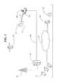
- FIG. 1is a diagrammatic view of the base station and other components of the communications method of the present invention.
- FIG. 2is a diagrammatic view of the components of the present invention with a user pendant and portable device within proximity to the base station.
- FIG. 3is a diagrammatic view of the components of the present invention with the portable device not in proximity to the base station.
- FIG. 4is a schematic diagram of the base station utilized with the method of the present invention.
- FIG. 5is a schematic view of the portable device utilized with the method of the present invention.
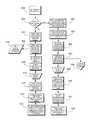
- FIG. 6is a flow chart showing the process steps of a presently preferred embodiment of the present invention.
- FIG. 7is a flow chart showing the process steps of alternative embodiments of the method of the present invention.
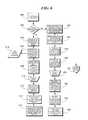
- FIG. 8is a flow chart showing the process steps of still further embodiments of the method of the present invention.
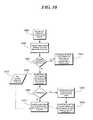
- FIG. 9is a flow chart showing the process steps of a still further embodiment of the method of the present invention.
- FIG. 10is a flow chart showing the process steps of yet another embodiment of the method of the present invention.
- FIG. 1the basic components utilized with the methods of the present invention are illustrated. These major components include a base station 400 , a portable device 500 , GPS satellite 20 , a cellular tower 30 , response center/call center 40 , 42 , the Internet 46 , a remote caregiver 60 , and the remote caregiver's computer 50 .
- the base station 400is aware that the user is outside the home when the cellular device 500 is no longer in communication with the base station.
- a signalcan be sent to the response center 40 , 42 to log that the user 10 is no longer at home,
- the GPS satellite 20receives a GPS signal 22 from the portable device 500 when the portable device 500 is outside the range of the home base station 400 .
- the portable device 500logs data and periodically sends data to the response center 40 , 42 via a cellular data connection.
- a GSM GPRS communication link 32 with voice and dataprovides communication with the cell tower 30 .
- the portable device 500When activated, the portable device 500 will dial a predetermined number and be connected to the response center 40 , 42 through line 34 .
- a GPS locationwill be sent via the data link while the call is taking place.
- the portable device 500will periodically send location data via the cellular data link at predetermined intervals.
- the response center 40is connected to the base station 400 by means of a PSTN connection 404 .
- the response center 40is connected to the Internet 46 by line 44 which also provides a link to a computer 50 located at the location of a remote caregiver 60 .
- the response center 40is manned by terminals or PCs 42 at the center.
- the RFID pendant 12is shown to be in proximity to the base station 400 .
- the remote caregiver 60can log into the system with PC 50 to determine the location of the user 10 .
- a mapping featureallows the user 10 to be located and to track their movements.
- FIG. 2shows the same basic components as FIG. 1 but in FIG. 2 a simple RF connection 14 is established between the base station 400 and the RF pendant 12 .
- the user 10switches to the RF pendant 12 and places the cellular device 500 (portable device) in the charging cradle on the base station 400 .
- GPS datais not required and the GPS module is placed in a standby mode.
- the GSM GPRS communications linkin not required and this module is also placed in a standby mode.
- the base station 400is aware that the user 10 is inside the home when the portable cellular device 500 is in communication with the base station 400 and/or the portable cellular device 500 is charging in the cradle.
- a signalcan be sent to the response center 40 to log that the user 10 is at home. If the user 10 depresses the panic button on the RF pendant 12 when the pendant is out of range of the base station 400 , the RF pendant 12 will transmit a simple RF signal to the base station 400 . In this mode the remote caregiver 60 can log into the system to determine if the user 10 is at home or out of range of the base station 400 . In this standard mode, location data will not be provided on a routine basis.
- the base station 400is aware that the user 10 is outside the home when the cellular device 500 is no longer in communication with the base station 400 .
- This signalingis accomplished via standard RE protocol from the base station 400 to the portable device 500 .
- the base station 400is sending a ping on regular intervals to determine if the portable device 500 is in range.
- a signalcan be sent to the response center 40 to log that the user 10 is no longer at home.
- the GPS signal 22is received by the portable device 500 when the portable device 500 is outside the range of the home base station 400 from the GPS satellite 20 .
- a GSM GPRS communication link with both voice and data 32is provided and when activated the portable device 500 will dial a predetermined number and will be connected to the response center 40 . Upon connection to the response center 40 , the portable device 500 will send a DTMF signal in a 4 ⁇ 2 format to indicate the user 10 ID. The GPS location will be sent via the data link while the call is taking place.
- RE Pendant 12is in 1-way communication with both base station 400 and mobile device 500 .
- Mobile device 500is in 2-way communication with base station 400 and is also capable of directly communicating with response center 40 .
- both mobile device 500 (as discussed below) and base station 400 (as discussed above)are adapted to perform a function in response to a signal from pendant 12 .
- RF Pendant 12During operation depression of the panic button on RF Pendant 12 causes a 1-way panic signal to be produced.
- RE PendantWhen RE Pendant is in proximity of base station 400 , mobile device 500 is in communication with base station 400 as discussed above, and base station 400 , not mobile device 500 , will initiate a call as discussed above.
- Base station 400signals device 500 that they are in proximity so that mobile device 500 does not make a simultaneous call wasting assets and confusing any remote caregiver.
- the panic signalcauses mobile device 500 to execute the call to response center 40 and a caregiver 60 as discussed above.
- a simple pendantwhich may be hung around the neck or wrist may be used.
- the pendantis always accessible, as opposed to always carrying the larger mobile device 500 .
- the mobile device 500may now be carried in a pocket, purse or a pocketbook, gym bag, back pack or the like. This frees up the use of both hands.
- the base stationincludes a CPU Module 410 is provided which is connected by line 462 to a RS232/USB Converter 460 .
- This converter 460is connected via line 452 to a USB/B Connector 450 and to external power.
- a power regulator 442is connected by line 441 to an outlet 440 .
- a battery charging circuit 444is provided and is connected by line 445 to battery 446 .
- a 1-10 MB Serial Storage device 414can be connected to the CPU Module 410 via line 412 .
- an optional Ethernet connection 416 having a RJ-45 port 418 connected by line 417may be provided.
- CPU Module 410is connected by line 422 to a Modern 420 .
- the Modern 420is connected by line 423 to an RJ-11 port 424 .
- the CPU Module 410is connected by line 432 to a RFID Mesh Network Receiver 430 which is in turn connected by line 433 to an RFID Antenna 434 .
- base station 400may also be a wireless communication device making use of cellular telephone or radio frequency technologies. In this way, base station 400 is also somewhat portable capable of travel to hotels, vacation and second homes and the like. In this way, base station 400 need not be reinitialized, set up, or wired each time a user changes their domicile. Additionally, it is well within the scope of the invention that base station 400 is incorporated into the security system of the home and may be part of the installed alarm box. Additionally, in a preferred embodiment, base station 400 , pendant 12 and mobile device 500 communicate using RF signals, however, any mode of communication between electronic devices enabling the functionality described above is within the scope of the invention.
- the portable device 500includes a cellular phone mobile 510 .
- a USB connector 512is connected to a RS232/USB Converter 514 .
- the Module 510is connected to a power source 530 and is also connected to battery 534 .
- a first LED 520 and a second LED 522are provided.
- Module 510is also connected to a GPS Preamp 540 which has a GPS Antenna 542 .
- a plug-in socket 545may be utilized to connect various components including an Audio Board 550 , a Display Board 560 , an RFID Board 570 , a Bluetooth Module 580 and a simple RF board 590 .
- the method of the present inventionis designed to have a use model which includes the following features and functions.
- the Portable 500 devicewill primarily be used when the subscriber leaves the home and is no longer in range of the Base Station 400 . When the subscriber is at home, the Portable Device 500 will be in proximity to the Base Station 400 and will be reduced to low power mode in which the cellular components are turned to hibernate and the GPS and RF receivers are turned off. Ideally, the Portable Device 500 will be placed in a charging base which is integrated into the Base Station. The Portable Device 500 will also have an RE communicator so that the device can send an alert to base station 400 if depressed and receive RF signals from the pendant 12 ′ when activated.
- the deviceWhen the Portable Device 500 is in the charging cradle, the device is placed into low power mode.
- the charging cradleis built into the base station 400 .
- the base station 400is capable of sending a signal via auto-dialer to indicate that the Portable Device 500 is at home. In this mode, either pendant 12 or pendant 12 ′ working through mobile device 500 causes base station 400 to transmit the call to the response center.
- the Portable Device 500When the Portable Device 500 is at home (as a preferred optional service), once you leave the proximity of the Base Station 400 the cellular device is turned on and the GPS is instructed to get a fix. Once the initial location is acquired, the GPS will be placed into a low power mode which acquires a fix at specified intervals which will be set to optimize battery life. The device will be in listening mode to detect instructions from potential inquiries. If the user has an emergency, the button of mobile device 500 is depressed and the device automatically dials a predetermined number to the response center. The call is received by the monitoring station and a DTMF code (6 digits in a 4 by 2 format) is sent to identify the user and held until an operator answers. A two-way voice communication is used to determine the issue. As the call is initiated, the location data and user data is being sent via a cellular data protocol such as GPRS to the back end system.
- a cellular data protocolsuch as GPRS
- the RF Pendant 12utilized with the present method is used as follows: When the user is in the home, the RF Pendant 12 is used as the communicator to the Base Station 400 . If a button on RF Pendant 12 is depressed the RF module will send a simple data stream to be processed by Base Station 400 indicating an alarm is being initiated. Alternatively, in a less preferred embodiment, mobile device 500 may receive the signal and communicate with base station 400 .
- the RF Pendant 12 ′illustrates the situation of the pendant 12 ′ being out of the proximity of base station 400 in tandem with mobile device 500 .
- Pressing a panic button on pendant 12 ′produces the RF signal, which is not received by base station 400 as it is out of range.
- mobile device 500receives the signal which triggers the auto dialer process to the response center as discussed above.
- mobile device 500may be a smart phone upon which an application is loaded, the application causing the mobile device 500 to auto dial the response center and upload location information and user identification information to be used at the response center 40 , 42 .
- the softwarewill be licensed from a current manufacturer of response center software. Location data will need to be added along with a presentation layer.
- a databaseis maintained at response center/emergency response center 40 , 42 .
- the databaseincludes a profile associated with each user 10 .
- the databaseis accessed at the emergency response center 40 , 42 to determine an appropriate action to be taken such as notify caregiver 60 .
- caregiver 60may be a relative, a neighbor or an individual who knows user 10 and will respond appropriately.
- the first devices utilized with the present methodswould use existing modules.
- a Rabbit Core ModulesRCM3700
- the Rabbit modulescome with a built in Ethernet connection, and libraries that already can use the Xbee module, MultiTech Modem, Ethernet, BlueTooth and other communication protocols.
- the RCM4000comes with expanded memory, which can be used for data logging.
- the MultiTech MT5600SMI-L-34.R2-SPis a plug in device that will allow dial-up on a POT's line.
- the MaxStream Xbee modulecan be used to communicate with the remote devices.
- a standard plug-in pack power supplywill connect to a wall outlet. An onboard power supply will convert this power into what is needed to power the base station, and charge the plug-in devices.
- 1.2V Ni-Cad cellscan be used to provide short term power in the event of a power failure.
Landscapes
- Engineering & Computer Science (AREA)
- Radar, Positioning & Navigation (AREA)
- Remote Sensing (AREA)
- Physics & Mathematics (AREA)
- General Physics & Mathematics (AREA)
- Computer Networks & Wireless Communication (AREA)
- Computer Security & Cryptography (AREA)
- Business, Economics & Management (AREA)
- Emergency Management (AREA)
- Alarm Systems (AREA)
- Mobile Radio Communication Systems (AREA)
- Telephone Function (AREA)
Abstract
Description
- 600—User is wearing
portable device 500. - 602—Is user in proximity to
base station 400. - 604—
Portable Device 500 activates cellular components as well as GPS module. - 606—
Portable Device 500 begins to collect and store into memory location data collected by GPS receiver. - 608—
Portable Device 500 goes into a lower power configuration, sending occasional location, monitoring cellular network and emergency button. - 610—Emergency button on
portable device 500 is depressed. - 612—
Portable Device 500 initiates auto dial call sequence to emergency response center. - 614—
Emergency response - 616—
Emergency response center - 618—GPS location data stored for later use.
- 620—Portable Device powers down the GPS, puts cell in sleep mode, and sends a signal to the base station indicating that it is in proximity,
- 622—The
Base Station 400 dials response center and transmits a code indicating that thePortable device 500 is in range. - 624—Emergency response center,40,42 receives the code and logs it in the system database.
- 626—
Portable device 500 continues to monitor proximity ofbase station 400 via RF communication. - 628—Emergency button on
portable device 500 depressed. - 630—
Portable Device 500 sends RF signal to Base Station to initiate emergency call. Also activates cellular radio and sends redundant signal. - 632—
Base Station 400 receives emergency signal and initiates auto dial sequence to response center. - 634—
Emergency response center - 636—
Portable Device 500 Out of Range.
- 600—User is wearing
- 700—User is Wearing
RF Pendant 12 - 702—Is User in Proximity of
Base Station 400 - 704—Is User wearing
portable device 500 - 706—Emergency button on
RF Pendant 12 depressed. - 708—
RF Pendant 12 sends RF signal toportable device 500 to initiate emergency call. - 710—
Portable Device 500 receives emergency signal and initiates location sequence toresponse center - 712
Emergency response center - 714—
RF Pendant 12 is not able to communicate (and therefore does not function) outside the range of theBase Station 400 andmobile device 500. - 716 Emergency button on
pendant 12 is depressed. - 718—
Portable Device 500 sends RF signal to Base Station to initiate emergency call. - 720—
Base Station 400 receives emergency signal and initiates auto dial sequence to response center. - 722—
Emergency response center
- 700—User is Wearing
- 800—Location Request Initiated by
Caregiver 60 via theInternet 46. - 802—Database lookup initiated based on user ID and password authentication.
- 804—Database indicates that
User 10 is home. - 806—
Portable device 500 is sent a signal to indicate its current location. - 808—Is GPS locked?
- 810—Is there existing GPS data?
- 812—
Portable Device 500 receives last known location from memory and sends to system. - 814—GPS location data stored for later use.
- 816—
Caregiver 60 given the “at home” indication bysystem - 818—Portable device sends the latest received coordinates to the system.
- 820—Send
cell tower 30 information for triangulation.
- 800—Location Request Initiated by
- 900—
Portable Device 500 Out of Range. - 902—
Portable Device 500 determines that it is no longer in range of theBase Station 400. - 904—
Portable device 500 sends a signal via GPRS to theemergency response center Base Station 400. - 906—
Emergency response center
- 900—
- 1000—Voice Request Initiated by
Caregiver 60 via theInternet 46. - 1002—Database lookup initiated based on User ID and password authentication.
- 1004—Database indicates that
User 10 is home. - 1006—
Portable Device 500 is sent a signal to dial a number sent to it. - 1008—Is GPS locked?
- 1010—
Portable Device 500 retrieves the last know location from memory and sends tosystem - 1012—GPS location data stored for later use.
- 1014—
Caregiver 60 the “at home” indication by system, and uses conventional communications to contact patient. - 1016—
Portable device 500 sends the latest received coordinates to the System. - 1018—
Portable device 500 dials the caregiver number, and auto connects,Caregiver 60 speaks to patient via speakerphone.
- 1000—Voice Request Initiated by
Claims (8)
Priority Applications (2)
| Application Number | Priority Date | Filing Date | Title |
|---|---|---|---|
| US12/819,865US8447265B2 (en) | 2009-02-03 | 2010-06-21 | Proximity based emergency communication system |
| PCT/US2011/041205WO2011163196A1 (en) | 2010-06-21 | 2011-06-21 | Communications method |
Applications Claiming Priority (2)
| Application Number | Priority Date | Filing Date | Title |
|---|---|---|---|
| US12/322,566US8086250B2 (en) | 2009-02-03 | 2009-02-03 | Communications method |
| US12/819,865US8447265B2 (en) | 2009-02-03 | 2010-06-21 | Proximity based emergency communication system |
Related Parent Applications (1)
| Application Number | Title | Priority Date | Filing Date |
|---|---|---|---|
| US12/322,566Continuation-In-PartUS8086250B2 (en) | 2009-02-03 | 2009-02-03 | Communications method |
Publications (2)
| Publication Number | Publication Date |
|---|---|
| US20100311388A1 US20100311388A1 (en) | 2010-12-09 |
| US8447265B2true US8447265B2 (en) | 2013-05-21 |
Family
ID=45371780
Family Applications (1)
| Application Number | Title | Priority Date | Filing Date |
|---|---|---|---|
| US12/819,865Active - ReinstatedUS8447265B2 (en) | 2009-02-03 | 2010-06-21 | Proximity based emergency communication system |
Country Status (2)
| Country | Link |
|---|---|
| US (1) | US8447265B2 (en) |
| WO (1) | WO2011163196A1 (en) |
Cited By (8)
| Publication number | Priority date | Publication date | Assignee | Title |
|---|---|---|---|---|
| US20140213281A1 (en)* | 2013-01-29 | 2014-07-31 | International Business Machines Corporation | Direction coupling discrimination of networked exchanges |
| US9734690B2 (en) | 2015-04-15 | 2017-08-15 | Nortek Security & Controls LLC | System and method for activity monitoring and fall detection |
| US9843911B2 (en) | 2013-09-23 | 2017-12-12 | At&T Intellectual Property I, L.P. | Remotely activated monitoring service |
| US20180225957A1 (en)* | 2014-05-22 | 2018-08-09 | West Corporation | System and method for reporting the existence of sensors belonging to multiple organizations |
| US20200279473A1 (en)* | 2019-02-28 | 2020-09-03 | Nortek Security & Control Llc | Virtual partition of a security system |
| US11626010B2 (en)* | 2019-02-28 | 2023-04-11 | Nortek Security & Control Llc | Dynamic partition of a security system |
| US12123654B2 (en) | 2010-05-04 | 2024-10-22 | Fractal Heatsink Technologies LLC | System and method for maintaining efficiency of a fractal heat sink |
| US12251201B2 (en) | 2019-08-16 | 2025-03-18 | Poltorak Technologies Llc | Device and method for medical diagnostics |
Families Citing this family (7)
| Publication number | Priority date | Publication date | Assignee | Title |
|---|---|---|---|---|
| US8488688B2 (en)* | 2004-10-29 | 2013-07-16 | Sharp Kabushiki Kaisha | Communication method and radio transmitter |
| JPWO2006077696A1 (en) | 2005-01-18 | 2008-06-19 | シャープ株式会社 | Wireless communication device, portable terminal, and wireless communication method |
| RU2588596C2 (en)* | 2011-03-30 | 2016-07-10 | Конинклейке Филипс Н.В. | Determination of distance and/or quality of acoustics between mobile device and base unit |
| CA2887443A1 (en)* | 2014-03-31 | 2015-09-30 | AWARE 360 Ltd. | Systems and methods for communication across multiple communications networks |
| GB2528915A (en)* | 2014-08-04 | 2016-02-10 | Steatite Ltd | Wearable tag |
| KR101810375B1 (en)* | 2015-05-15 | 2017-12-20 | 폴 그라아프스마 | Improved Mobile Personal Emergency Response System and Method of Use |
| FR3084805B1 (en)* | 2018-08-01 | 2020-11-06 | Horizon Telecom | DISTRESS WARNING DEVICE INCLUDING A BATTERY MANAGEMENT SYSTEM |
Citations (31)
| Publication number | Priority date | Publication date | Assignee | Title |
|---|---|---|---|---|
| US4598275A (en) | 1983-05-09 | 1986-07-01 | Marc Industries Incorporated | Movement monitor |
| US4814751A (en) | 1987-02-27 | 1989-03-21 | Wildlife Materials, Inc. | Patient tracking system |
| US5742233A (en) | 1997-01-21 | 1998-04-21 | Hoffman Resources, Llc | Personal security and tracking system |
| US5937355A (en)* | 1995-12-07 | 1999-08-10 | Telefonaktiebolaget Lm Ericsson (Publ) | Emergency call handling in a cellular telecommunication system |
| US6035217A (en)* | 1997-10-29 | 2000-03-07 | Sony Corporation Of Japan | One button cellular phone, system, and method for use |
| US6044257A (en)* | 1998-03-19 | 2000-03-28 | American Secure Care, Llc | Panic button phone |
| US6239700B1 (en) | 1997-01-21 | 2001-05-29 | Hoffman Resources, Inc. | Personal security and tracking system |
| US6339397B1 (en) | 2000-06-01 | 2002-01-15 | Lat-Lon, Llc | Portable self-contained tracking unit and GPS tracking system |
| US6400272B1 (en) | 1999-04-01 | 2002-06-04 | Presto Technologies, Inc. | Wireless transceiver for communicating with tags |
| US20030027547A1 (en)* | 2001-07-16 | 2003-02-06 | Gerald Wade | Emergency communication system |
| US6544171B2 (en) | 2000-02-25 | 2003-04-08 | Biotronik Mess- Und Therapiegerate Gmbh & Co. Ingenieurburo Berlin | System for patient monitoring |
| US6590525B2 (en) | 2000-02-24 | 2003-07-08 | Koninklijke Philips Electronics N.V. | GPS receiver and mobile unit incorporating the same |
| US6624754B1 (en) | 1998-01-20 | 2003-09-23 | Hoffman Resources Llc | Personal security and tracking system |
| US6636732B1 (en)* | 1998-03-19 | 2003-10-21 | Securealert, Inc. | Emergency phone with single-button activation |
| US6661340B1 (en) | 2001-04-24 | 2003-12-09 | Microstrategy Incorporated | System and method for connecting security systems to a wireless device |
| US6678514B2 (en) | 2000-12-13 | 2004-01-13 | Motorola, Inc. | Mobile personal security monitoring service |
| US6700533B1 (en) | 1999-05-06 | 2004-03-02 | Rf Technologies, Inc. | Asset and personnel tagging system utilizing GPS |
| US20050221796A1 (en) | 2004-03-31 | 2005-10-06 | Gerald Pellegrino | Personal portable security system |
| US7016478B2 (en)* | 2003-11-24 | 2006-03-21 | Lucent Technologies Inc. | 911 emergency voice/data telecommunication network |
| US20060154642A1 (en) | 2004-02-20 | 2006-07-13 | Scannell Robert F Jr | Medication & health, environmental, and security monitoring, alert, intervention, information and network system with associated and supporting apparatuses |
| US20060182076A1 (en) | 2005-02-17 | 2006-08-17 | Mobitrum Corporation | Method and system for mesh network embeded devices |
| US7138916B2 (en) | 2002-10-29 | 2006-11-21 | Jeffrey Schwartz | Computerized risk management program |
| US20070082652A1 (en) | 2003-05-26 | 2007-04-12 | Securecom Technologies Limited | Portable communications device |
| US20070270164A1 (en) | 2006-05-16 | 2007-11-22 | Red Sky Technologies, Inc. | System and method for an emergency location information service (E-LIS) |
| US20070293186A1 (en) | 2004-02-11 | 2007-12-20 | Ctl Analyzers, Llc | Systems and Methods for a Personal Safety Device |
| US20080227429A1 (en) | 2007-03-13 | 2008-09-18 | Research In Motion Limited | Enhanced handling of duress situations |
| US20090040041A1 (en) | 2007-08-10 | 2009-02-12 | Integrity Tracking, Llc | Alzheimer's patient tracking system |
| US20090143047A1 (en) | 2007-10-31 | 2009-06-04 | Hays William D | Method and system for mobile personal emergency response |
| US20090181638A1 (en)* | 2008-01-15 | 2009-07-16 | Mgpatents, Llc | Wireless, centralized emergency services system |
| US7864927B2 (en)* | 2005-02-01 | 2011-01-04 | Marion Alice Loizeaux | Multi-site personal emergency telephone system method and device |
| US7933581B2 (en)* | 2007-06-08 | 2011-04-26 | Research In Motion Limited | Methods and apparatus for use in processing disconnected emergency calls and other communications involving mobile communication devices and the remote monitoring thereof |
Family Cites Families (3)
| Publication number | Priority date | Publication date | Assignee | Title |
|---|---|---|---|---|
| JP2000288238A (en)* | 1999-04-02 | 2000-10-17 | Konami Co Ltd | Game system |
| US7442026B2 (en)* | 2004-08-23 | 2008-10-28 | Wm. Wrigley Jr. Company | Apparatuses for producing alternatively shaped confectionary products |
| US7680908B2 (en)* | 2006-09-28 | 2010-03-16 | Microsoft Corporation | State replication |
- 2010
- 2010-06-21USUS12/819,865patent/US8447265B2/enactiveActive - Reinstated
- 2011
- 2011-06-21WOPCT/US2011/041205patent/WO2011163196A1/enactiveApplication Filing
Patent Citations (35)
| Publication number | Priority date | Publication date | Assignee | Title |
|---|---|---|---|---|
| US4598275A (en) | 1983-05-09 | 1986-07-01 | Marc Industries Incorporated | Movement monitor |
| US4814751A (en) | 1987-02-27 | 1989-03-21 | Wildlife Materials, Inc. | Patient tracking system |
| US5937355A (en)* | 1995-12-07 | 1999-08-10 | Telefonaktiebolaget Lm Ericsson (Publ) | Emergency call handling in a cellular telecommunication system |
| US5742233A (en) | 1997-01-21 | 1998-04-21 | Hoffman Resources, Llc | Personal security and tracking system |
| US6239700B1 (en) | 1997-01-21 | 2001-05-29 | Hoffman Resources, Inc. | Personal security and tracking system |
| US20070243855A1 (en) | 1997-01-21 | 2007-10-18 | Hoffman Resources Llc | Personal security and tracking system |
| US7038590B2 (en) | 1997-01-21 | 2006-05-02 | Hoffman Recruiters Llc | Personal security and tracking system |
| US6035217A (en)* | 1997-10-29 | 2000-03-07 | Sony Corporation Of Japan | One button cellular phone, system, and method for use |
| US6624754B1 (en) | 1998-01-20 | 2003-09-23 | Hoffman Resources Llc | Personal security and tracking system |
| US6044257A (en)* | 1998-03-19 | 2000-03-28 | American Secure Care, Llc | Panic button phone |
| US6636732B1 (en)* | 1998-03-19 | 2003-10-21 | Securealert, Inc. | Emergency phone with single-button activation |
| US6400272B1 (en) | 1999-04-01 | 2002-06-04 | Presto Technologies, Inc. | Wireless transceiver for communicating with tags |
| US6700533B1 (en) | 1999-05-06 | 2004-03-02 | Rf Technologies, Inc. | Asset and personnel tagging system utilizing GPS |
| US6590525B2 (en) | 2000-02-24 | 2003-07-08 | Koninklijke Philips Electronics N.V. | GPS receiver and mobile unit incorporating the same |
| US6544171B2 (en) | 2000-02-25 | 2003-04-08 | Biotronik Mess- Und Therapiegerate Gmbh & Co. Ingenieurburo Berlin | System for patient monitoring |
| US6339397B1 (en) | 2000-06-01 | 2002-01-15 | Lat-Lon, Llc | Portable self-contained tracking unit and GPS tracking system |
| US6678514B2 (en) | 2000-12-13 | 2004-01-13 | Motorola, Inc. | Mobile personal security monitoring service |
| US6661340B1 (en) | 2001-04-24 | 2003-12-09 | Microstrategy Incorporated | System and method for connecting security systems to a wireless device |
| US6965313B1 (en) | 2001-04-24 | 2005-11-15 | Alarm.Com Inc. | System and method for connecting security systems to a wireless device |
| US20030027547A1 (en)* | 2001-07-16 | 2003-02-06 | Gerald Wade | Emergency communication system |
| US7138916B2 (en) | 2002-10-29 | 2006-11-21 | Jeffrey Schwartz | Computerized risk management program |
| US20070082652A1 (en) | 2003-05-26 | 2007-04-12 | Securecom Technologies Limited | Portable communications device |
| US7907931B2 (en)* | 2003-05-26 | 2011-03-15 | Securecom Technologies Limited | Portable communications device |
| US7016478B2 (en)* | 2003-11-24 | 2006-03-21 | Lucent Technologies Inc. | 911 emergency voice/data telecommunication network |
| US20070293186A1 (en) | 2004-02-11 | 2007-12-20 | Ctl Analyzers, Llc | Systems and Methods for a Personal Safety Device |
| US20060154642A1 (en) | 2004-02-20 | 2006-07-13 | Scannell Robert F Jr | Medication & health, environmental, and security monitoring, alert, intervention, information and network system with associated and supporting apparatuses |
| US20050221796A1 (en) | 2004-03-31 | 2005-10-06 | Gerald Pellegrino | Personal portable security system |
| US7864927B2 (en)* | 2005-02-01 | 2011-01-04 | Marion Alice Loizeaux | Multi-site personal emergency telephone system method and device |
| US20060182076A1 (en) | 2005-02-17 | 2006-08-17 | Mobitrum Corporation | Method and system for mesh network embeded devices |
| US20070270164A1 (en) | 2006-05-16 | 2007-11-22 | Red Sky Technologies, Inc. | System and method for an emergency location information service (E-LIS) |
| US20080227429A1 (en) | 2007-03-13 | 2008-09-18 | Research In Motion Limited | Enhanced handling of duress situations |
| US7933581B2 (en)* | 2007-06-08 | 2011-04-26 | Research In Motion Limited | Methods and apparatus for use in processing disconnected emergency calls and other communications involving mobile communication devices and the remote monitoring thereof |
| US20090040041A1 (en) | 2007-08-10 | 2009-02-12 | Integrity Tracking, Llc | Alzheimer's patient tracking system |
| US20090143047A1 (en) | 2007-10-31 | 2009-06-04 | Hays William D | Method and system for mobile personal emergency response |
| US20090181638A1 (en)* | 2008-01-15 | 2009-07-16 | Mgpatents, Llc | Wireless, centralized emergency services system |
Non-Patent Citations (1)
| Title |
|---|
| International Search Report from PCT/US11/041205. |
Cited By (12)
| Publication number | Priority date | Publication date | Assignee | Title |
|---|---|---|---|---|
| US12123654B2 (en) | 2010-05-04 | 2024-10-22 | Fractal Heatsink Technologies LLC | System and method for maintaining efficiency of a fractal heat sink |
| US20140213281A1 (en)* | 2013-01-29 | 2014-07-31 | International Business Machines Corporation | Direction coupling discrimination of networked exchanges |
| US9167380B2 (en) | 2013-01-29 | 2015-10-20 | International Business Machines Corporation | Activating a mobile device based on location of mobile device in a sector of a cell |
| US9179246B2 (en)* | 2013-01-29 | 2015-11-03 | International Business Machines Corporation | Direction coupling discrimination of networked exchanges |
| US9843911B2 (en) | 2013-09-23 | 2017-12-12 | At&T Intellectual Property I, L.P. | Remotely activated monitoring service |
| US20180225957A1 (en)* | 2014-05-22 | 2018-08-09 | West Corporation | System and method for reporting the existence of sensors belonging to multiple organizations |
| US10726709B2 (en)* | 2014-05-22 | 2020-07-28 | West Corporation | System and method for reporting the existence of sensors belonging to multiple organizations |
| US9734690B2 (en) | 2015-04-15 | 2017-08-15 | Nortek Security & Controls LLC | System and method for activity monitoring and fall detection |
| US20200279473A1 (en)* | 2019-02-28 | 2020-09-03 | Nortek Security & Control Llc | Virtual partition of a security system |
| US11626010B2 (en)* | 2019-02-28 | 2023-04-11 | Nortek Security & Control Llc | Dynamic partition of a security system |
| US12165495B2 (en)* | 2019-02-28 | 2024-12-10 | Nice North America Llc | Virtual partition of a security system |
| US12251201B2 (en) | 2019-08-16 | 2025-03-18 | Poltorak Technologies Llc | Device and method for medical diagnostics |
Also Published As
| Publication number | Publication date |
|---|---|
| WO2011163196A1 (en) | 2011-12-29 |
| US20100311388A1 (en) | 2010-12-09 |
Similar Documents
| Publication | Publication Date | Title |
|---|---|---|
| US8447265B2 (en) | Proximity based emergency communication system | |
| US8086250B2 (en) | Communications method | |
| US8270938B2 (en) | Managing battery power for mobile emergency communication device | |
| US11792605B2 (en) | Tracking device systems | |
| US9485613B2 (en) | Wireless pairing and tracking system for locating lost items | |
| US9823342B2 (en) | System and method for mobile monitoring of non-associated tags | |
| US7961092B2 (en) | Active wireless tag and auxiliary device for use with monitoring center for tracking individuals or objects | |
| US8937554B2 (en) | Low power location-tracking device with combined short-range and wide-area wireless and location capabilities | |
| US9002372B2 (en) | Locating system for autistic child and others | |
| US8102316B1 (en) | System and method for tracking lost subjects | |
| EP1831850B1 (en) | Position finding system for people, animals and objects | |
| JP2012165300A (en) | Wanderer position management system | |
| KR101060919B1 (en) | Automatic Distress Report System Using Zigbee Communication | |
| CN105046875A (en) | Infant monitoring system and method | |
| US20100309046A1 (en) | Communications method | |
| US10440541B2 (en) | Beacon having multiple communication interfaces | |
| CN204965010U (en) | Multi -function watch and because remote monitering system of multi -function watch | |
| JP6985554B1 (en) | Location search system and location search method | |
| JP6976473B1 (en) | Location search system and location search method | |
| US11197144B2 (en) | Portable energy storage system for rescue system | |
| CN210277143U (en) | Monitoring device and monitoring system | |
| US9020526B1 (en) | Extensible tracking system | |
| WO2025166284A1 (en) | Monitoring device |
Legal Events
| Date | Code | Title | Description |
|---|---|---|---|
| AS | Assignment | Owner name:INTEGRITY TRACKING, LLC, FLORIDA Free format text:ASSIGNMENT OF ASSIGNORS INTEREST;ASSIGNORS:FLIPPO, ROBERT;JANETIS, ELIAS;REEL/FRAME:024613/0132 Effective date:20100616 Owner name:INTEGRITY TRACKING, LLC, FLORIDA Free format text:ASSIGNMENT OF ASSIGNORS INTEREST;ASSIGNORS:FLIPPO, ROBERT;JANETIS, ELIAS;REEL/FRAME:024628/0084 Effective date:20100616 | |
| STCF | Information on status: patent grant | Free format text:PATENTED CASE | |
| AS | Assignment | Owner name:THE PRIVATEBANK AND TRUST COMPANY, ILLINOIS Free format text:ACKNOWLEDGEMENT OF SECURITY INTEREST IN PATENTS;ASSIGNOR:INTEGRITY TRACKING, LLC;REEL/FRAME:031248/0743 Effective date:20130918 | |
| AS | Assignment | Owner name:THE PRIVATEBANK AND TRUST COMPANY, ILLINOIS Free format text:ACKNOWLEDGEMENT OF SECURITY INTEREST IN PATENTS;ASSIGNOR:INTEGRITY TRACKING, LLC;REEL/FRAME:036020/0339 Effective date:20140711 | |
| FPAY | Fee payment | Year of fee payment:4 | |
| AS | Assignment | Owner name:THE PRIVATEBANK AND TRUST COMPANY, ILLINOIS Free format text:ACKNOWLEDGEMENT OF SECURITY INTEREST IN PATENTS;ASSIGNOR:INTEGRITY TRACKING, LLC;REEL/FRAME:041778/0176 Effective date:20170222 Owner name:INTEGRITY TRACKING, LLC, FLORIDA Free format text:RELEASE OF SECURITY GRANT - PATENTS;ASSIGNOR:THE PRIVATEBANK AND TRUST COMPANY;REEL/FRAME:041778/0158 Effective date:20170222 | |
| AS | Assignment | Owner name:FMP AGENCY SERVICES, LLC, AS AGENT, MASSACHUSETTS Free format text:SECURITY AGREEMENT;ASSIGNOR:INTEGRITY TRACKING, LLC;REEL/FRAME:041808/0097 Effective date:20170222 | |
| AS | Assignment | Owner name:MOBILEHELP, LLC, FLORIDA Free format text:ASSIGNMENT OF ASSIGNORS INTEREST;ASSIGNOR:INTEGRITY TRACKING, LLC;REEL/FRAME:045932/0838 Effective date:20180226 | |
| AS | Assignment | Owner name:MOBILEHELP, LLC, FLORIDA Free format text:ASSIGNMENT OF ASSIGNORS INTEREST;ASSIGNOR:INTEGRITY TRACKING, LLC;REEL/FRAME:045928/0008 Effective date:20180326 | |
| AS | Assignment | Owner name:CIBC BANK USA, ILLINOIS Free format text:ACKNOWLEDGMENT OF SECURITY INTEREST IN PATENTS;ASSIGNOR:MOBILEHELP, LLC;REEL/FRAME:049285/0245 Effective date:20190429 | |
| FEPP | Fee payment procedure | Free format text:MAINTENANCE FEE REMINDER MAILED (ORIGINAL EVENT CODE: REM.); ENTITY STATUS OF PATENT OWNER: SMALL ENTITY | |
| LAPS | Lapse for failure to pay maintenance fees | Free format text:PATENT EXPIRED FOR FAILURE TO PAY MAINTENANCE FEES (ORIGINAL EVENT CODE: EXP.); ENTITY STATUS OF PATENT OWNER: SMALL ENTITY | |
| STCH | Information on status: patent discontinuation | Free format text:PATENT EXPIRED DUE TO NONPAYMENT OF MAINTENANCE FEES UNDER 37 CFR 1.362 | |
| FP | Lapsed due to failure to pay maintenance fee | Effective date:20210521 | |
| FEPP | Fee payment procedure | Free format text:PETITION RELATED TO MAINTENANCE FEES FILED (ORIGINAL EVENT CODE: PMFP); ENTITY STATUS OF PATENT OWNER: SMALL ENTITY | |
| AS | Assignment | Owner name:MOBILEHELP, LLC F/K/A INTEGRITY TRACKING, LLC, FLORIDA Free format text:RELEASE BY SECURED PARTY;ASSIGNOR:CIBC BANK USA;REEL/FRAME:059475/0262 Effective date:20220401 | |
| AS | Assignment | Owner name:MOBILEHELP, LLC, FLORIDA Free format text:RELEASE OF PATENT SECURITY INTERESTS;ASSIGNOR:FMP AGENCY SERVICES, LLC;REEL/FRAME:059593/0463 Effective date:20220401 | |
| FEPP | Fee payment procedure | Free format text:PETITION RELATED TO MAINTENANCE FEES GRANTED (ORIGINAL EVENT CODE: PTGR); ENTITY STATUS OF PATENT OWNER: SMALL ENTITY | |
| FEPP | Fee payment procedure | Free format text:PETITION RELATED TO MAINTENANCE FEES DISMISSED (ORIGINAL EVENT CODE: PMFS); ENTITY STATUS OF PATENT OWNER: SMALL ENTITY | |
| FEPP | Fee payment procedure | Free format text:SURCHARGE, PETITION TO ACCEPT PYMT AFTER EXP, UNINTENTIONAL. (ORIGINAL EVENT CODE: M2558); ENTITY STATUS OF PATENT OWNER: SMALL ENTITY Free format text:PETITION RELATED TO MAINTENANCE FEES FILED (ORIGINAL EVENT CODE: PMFP); ENTITY STATUS OF PATENT OWNER: SMALL ENTITY | |
| MAFP | Maintenance fee payment | Free format text:PAYMENT OF MAINTENANCE FEE, 8TH YR, SMALL ENTITY (ORIGINAL EVENT CODE: M2552); ENTITY STATUS OF PATENT OWNER: SMALL ENTITY Year of fee payment:8 | |
| REFU | Refund | Free format text:REFUND - SURCHARGE, PETITION TO ACCEPT PYMT AFTER EXP, UNINTENTIONAL (ORIGINAL EVENT CODE: R2558); ENTITY STATUS OF PATENT OWNER: SMALL ENTITY | |
| PRDP | Patent reinstated due to the acceptance of a late maintenance fee | Effective date:20230110 | |
| FEPP | Fee payment procedure | Free format text:PETITION RELATED TO MAINTENANCE FEES GRANTED (ORIGINAL EVENT CODE: PMFG); ENTITY STATUS OF PATENT OWNER: SMALL ENTITY | |
| STCF | Information on status: patent grant | Free format text:PATENTED CASE | |
| AS | Assignment | Owner name:MIDCAP FINANCIAL TRUST, AS ADMINISTRATIVE AGENT, MARYLAND Free format text:SECURITY INTEREST;ASSIGNOR:MOBILEHELP, LLC;REEL/FRAME:068574/0915 Effective date:20240911 | |
| MAFP | Maintenance fee payment | Free format text:PAYMENT OF MAINTENANCE FEE, 12TH YR, SMALL ENTITY (ORIGINAL EVENT CODE: M2553); ENTITY STATUS OF PATENT OWNER: SMALL ENTITY Year of fee payment:12 |