US8446819B2 - System and method for detecting and isolating a remote loop - Google Patents
System and method for detecting and isolating a remote loopDownload PDFInfo
- Publication number
- US8446819B2 US8446819B2US13/090,118US201113090118AUS8446819B2US 8446819 B2US8446819 B2US 8446819B2US 201113090118 AUS201113090118 AUS 201113090118AUS 8446819 B2US8446819 B2US 8446819B2
- Authority
- US
- United States
- Prior art keywords
- network
- loop
- port
- network device
- identifier
- Prior art date
- Legal status (The legal status is an assumption and is not a legal conclusion. Google has not performed a legal analysis and makes no representation as to the accuracy of the status listed.)
- Expired - Fee Related, expires
Links
- 238000000034methodMethods0.000titleclaimsabstractdescription37
- 238000001514detection methodMethods0.000claimsabstractdescription9
- 230000000903blocking effectEffects0.000claimsdescription23
- 238000004578scanning tunneling potentiometryMethods0.000description13
- 235000019832sodium triphosphateNutrition0.000description13
- 238000010586diagramMethods0.000description6
- 238000004891communicationMethods0.000description4
- 230000006870functionEffects0.000description3
- 230000015572biosynthetic processEffects0.000description2
- 238000012986modificationMethods0.000description2
- 230000004048modificationEffects0.000description2
- 230000002411adverseEffects0.000description1
- 230000005540biological transmissionEffects0.000description1
- 238000010276constructionMethods0.000description1
- 230000000694effectsEffects0.000description1
- 238000005516engineering processMethods0.000description1
- 239000000835fiberSubstances0.000description1
- 238000005111flow chemistry techniqueMethods0.000description1
- 238000002955isolationMethods0.000description1
- 239000013307optical fiberSubstances0.000description1
- 230000035755proliferationEffects0.000description1
- 238000011084recoveryMethods0.000description1
Images


Classifications
- H—ELECTRICITY
- H04—ELECTRIC COMMUNICATION TECHNIQUE
- H04L—TRANSMISSION OF DIGITAL INFORMATION, e.g. TELEGRAPHIC COMMUNICATION
- H04L12/00—Data switching networks
- H04L12/28—Data switching networks characterised by path configuration, e.g. LAN [Local Area Networks] or WAN [Wide Area Networks]
- H04L12/46—Interconnection of networks
- H04L12/4604—LAN interconnection over a backbone network, e.g. Internet, Frame Relay
- H04L12/462—LAN interconnection over a bridge based backbone
- H04L12/4625—Single bridge functionality, e.g. connection of two networks over a single bridge
- H—ELECTRICITY
- H04—ELECTRIC COMMUNICATION TECHNIQUE
- H04L—TRANSMISSION OF DIGITAL INFORMATION, e.g. TELEGRAPHIC COMMUNICATION
- H04L45/00—Routing or path finding of packets in data switching networks
- H04L45/18—Loop-free operations
- H—ELECTRICITY
- H04—ELECTRIC COMMUNICATION TECHNIQUE
- H04L—TRANSMISSION OF DIGITAL INFORMATION, e.g. TELEGRAPHIC COMMUNICATION
- H04L45/00—Routing or path finding of packets in data switching networks
- H04L45/48—Routing tree calculation
Definitions
- the inventionrelates to network configuration protocols, and, more particularly, to protocols which enable remote loop detection and allow for isolation of those remote loops.
- a computer networktypically comprises a plurality of interconnected devices, These devices include any network device, such as a server or end station, that transmits or receives data frames.
- a common type of computer networkis a local area network (“LAN”) which typically refers to a privately owned network within a single building or campus.
- LANsmay employ a data communication protocol, such as Ethernet or token ring, that defines the functions performed by the data link and physical layers of a communications architecture in the LAN.
- LANsare interconnected by point-to-point links, microwave transceivers, satellite hook-ups, etc. to form a wide area network (“WAN”), that may span an entire country or continent.
- WANwide area network
- One or more intermediate network devicesare often used to couple LANs together and allow the corresponding entities to exchange information.
- a bridgemay be used to provide a bridging function between two or more LANs.
- a switchmay be utilized to provide a switching function for transferring information among a plurality of LANs or end stations.
- a switchis a bridge among more than 2 networks or entities.
- the terms “bridge” and “switch”will be used interchangeably throughout this description.
- Bridges and switchesare typically devices that operate at the Data Link layer (“layer 2 ”) of the Open Systems Interconnection (“OSI”) model. Their operation is defined in the American National Standards Institute (“ANSI”) Institute of Electrical and Electronics Engineers (“IEEE”) 802.1D standard. A copy of the ANSI/IEEE Standard 802.1D, 1998 Edition, is incorporated by referenced herein in its entirety.
- ANSIAmerican National Standards Institute
- IEEEInstitute of Electrical and Electronics Engineers
- Telecommunication traffic among network devicesis divided into seven layers under the OSI model and the layers themselves split into two groups.
- the upper four layersare used whenever a message passes to or from a user.
- the lower three layersare used when any message passes through the host computer, whereas messages intended for the receiving computer pass to the upper four layers.
- Layer 2refers to the data-link layer, which provides synchronization for the physical level and furnishes transmission protocol knowledge and management.
- Networksmay be designed using a plurality of distinct topologies—that is the entities in the network may be coupled together in many different ways.
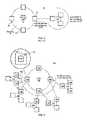
- FIGS. 1-3there is shown different examples of “ring” topologies.
- a ring topologyis a network configuration formed when “Layer 2” bridges are placed in a circular fashion with each bridge having two and only two ports belonging to a specific ring.
- FIG. 1shows a single ring 50 having bridges 52 connected by paths 54 .
- Each bridge 52 in ring 50 in FIG. 1has two ports 52 a and 52 b belonging to the ring.
- FIG. 2shows two adjacent rings, 50 a and 50 b , with a single bridge 56 having two ports 56 a , 56 b belonging to each ring.
- FIGS. 1 and 2no paths or bridges are shared among rings.
- two rings 50 c and 50 dare connected and share two bridges 58 , 60 .
- Bridge 58has two ports 58 a and 58 b which each uniquely belong to only one ring, rings 50 c and 50 d respectively.
- Bridge 58also has one port 58 c connected to a path which is shared by both rings 50 c and 50 d . If rings are assigned different priority levels, a port such as 58 c connected to the shared link assumes the priority value of the higher priority ring, and ports 58 a and 58 b in shared bridge 58 and port 60 a in bridge 60 connected to the lower priority ring are deemed to be customer (or lower priority) ports.
- the use of a shared link between shared bridges 58 , 60allows for the connection of rings and the growth of a larger network from smaller ring components; however, the shared link also presents difficulties since its failure affects both rings 50 c and 50 d.
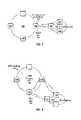
- Ring topologies shown in FIGS. 1-3present Layer 2 traffic looping problems.
- data trafficcan circulate around in either direction past their origination and thus create repetition of messages.
- data trafficmay originate in bridge 51 , travel counter-clockwise in the ring, pass bridge 57 and return to bridge 51 ; this is called a loop.
- Loopsare highly undesirable because data frames may traverse the loops indefinitely.
- switches and bridgesreplicate (i.e., flood) frames whose destination port is unknown or which are directed to broadcast or multicast addresses, the existence of loops may cause a proliferation of data frames that effectively overwhelms the network.
- one of the paths in the ringis blocked, as shown in FIG. 4 , by blocking data traffic in one of the ring ports—in this case, either port 51 a or 57 a .
- the portis deemed to be in a “blocking” state, in which it does not learn or forward incoming or outgoing traffic.
- a networkmay be segregated into a series of logical network segments. For example, any number of physical ports of a particular switch may be associated with any number of other ports by using a virtual local area network (“VLAN”) arrangement that virtually associates the ports with a particular VLAN designation. Multiple ports may thus form a VLAN even though other ports may be physically disposed between these ports.
- VLANvirtual local area network
- the VLAN designation for each local portis stored in a memory portion of the switch such that every time a message is received by the switch on a local port the VLAN designation of that port is associated with the message. Association is accomplished by a flow processing element which looks up the VLAN designation in the memory portion based on the local port where the message originated.
- Most networksinclude redundant communications paths so that a failure of any given link or device does not isolate any portion of the network. For example, in the ring networks shown in FIGS. 1-4 , if communication is blocked preventing data from flowing counter-clockwise, the data may still reach its destination by moving counter-clockwise. The existence of redundant links, however, may also cause the formation of loops within the network.
- BPDUsBridge Protocol Data Units
- a network 80comprising a core or higher priority network such as a provider 70 coupled to a customer or lower priority network 72 through a switch 74 .
- Core network 70runs a conventional spanning tree protocol to avoid loops and has defined a blocked path 76 . This means that either port 78 or port 80 is blocked.
- Many different causesmay result in involuntary loops which may collapse the entire network 80 including: STP corrupted BPDUs, unidirectional optical fibers which result, for example, when paths which typically comprise two fibers but one has shut down, and non-configured protocols in loop topologies.
- STP corrupted BPDUsunidirectional optical fibers which result, for example, when paths which typically comprise two fibers but one has shut down
- non-configured protocols in loop topologiesIn the example in FIG.
- the first networkruns a first instance of a Spanning Tree Protocol and the second network runs either a different instance or no instance.
- the methodincludes sending a Remote Loop Detection Packet (“RLDP”) from the ports in bridges of the first network which are connected to the second network.
- the RLDPincludes identifiers such as the source bridge, port and VLAN.
- the system and methodfurther includes checking for receipt of the RLDP on the same bridge which sent the RLDP. If such a receipt occurs, a loop is detected and one of the ports of the receiving/sending bridge is blocked.
- a methodenables a first network to detect a loop in a second network.
- the second networkis connected to the first network.
- the first networkis running a first loop avoidance protocol such a STP.
- the second networkis either running a different instance of a loop avoidance protocol or not running any protocol at all.
- the methodincludes sending a first loop packet from a first port in a bridge running a loop avoidance protocol of the first network.
- the first loop packetincludes a first identifier with a first reference to the first port.
- the methodfurther includes receiving a second loop packet at the bridge, the second loop packet including a second identifier with a second reference to a second port.
- the methodstill further includes decoding the second loop packet to determine the second reference, comparing the second reference with the first reference, and detecting the loop in the second network when the first and second references match.
- a systemenables a first network to detect a loop in a second network.
- the second networkis communicably coupled to the first network.
- the first networkis running a first loop avoidance protocol instance, the second network is not running the first loop avoidance protocol instance.
- the systemcomprises a first network, a bridge in the first network; and a first port in the bridge.
- the first portsends a first loop packet including a first identifier with a first reference to the first port.
- the bridgereceives a second loop packet, the second loop packet including a second identifier with a second reference to a second port.
- the bridgefurther determines the second reference, compares the second reference with the first reference, and detects the loop in the second network when the first and second references match.
- a bridge in a first networkis communicably coupled to a second network.
- the first networkis running a first loop avoidance protocol instance.
- the second networkis not running the first loop avoidance protocol instance.
- the bridgecomprises a first port.
- the first portsends a first loop packet including a first identifier with a first reference to the first port.
- the bridgereceives a second loop packet, the second loop packet including a second identifier with a second reference to a second port.
- the bridgefurther determines the second reference, compares the second reference with the first reference, and detects a loop in a second network when the first and second references match.
- a computer readable storage mediumincludes computer executable code for enabling a first network to detect a loop in a second network.
- the second networkis communicably coupled to the first network.
- the first networkis running a first loop avoidance protocol instance.
- the second networkis not running the first loop avoidance protocol instance.
- the codeperforms the steps of sending a first loop packet from a first port in a bridge of the first network, the first loop packet including a first identifier with a first reference to the first port.
- the codefurther performs receiving a second loop packet at the bridge, the second loop packet including a second identifier with a second reference to a second port.
- the codedetermines the second reference, compares the second reference with the first reference and detects the loop in the second network when the first and second references match.
- a systemenables a first network to detect a loop in a second network.
- the second networkbeing communicably coupled to the first network.
- the first networkrunning a first loop avoidance protocol instance, the second network not running the first loop avoidance protocol instance.
- the systemcomprises a first network and a plurality of bridges in the first network.
- the systemfurther comprises a plurality of ports, at least one port for each of the bridges.
- Each port connected to the second networksends a respective first loop packet including a first identifier with a first reference to the respective port.
- Each bridgereceives a respective second loop packet, each second loop packet including a respective second identifier with a respective second reference to a respective second port.
- Each respective bridgefurther determines the respective second reference, compares the respective second reference with the respective first reference, and detects a loop in the second network when the respective first and respective second references match.
- Still yet another aspect of the inventionis a method for enabling a first network to detect a loop in a second network communicably coupled to the first network.
- the first networkis running a first loop avoidance protocol instance.
- the second networkis not running the first loop avoidance protocol instance.
- the methodcomprises running a second protocol in the first network to detect a loop in the second network and protecting the first network when a loop is detected in the second network.
- Yet still another aspect of the inventionis a system for enabling a first network to detect a loop in a second network communicably coupled to the first network.
- the systemcomprises a first network running a first loop avoidance protocol instance.
- a second networkis not running the first loop avoidance protocol instance.
- the first networkruns a second loop avoidance protocol instance to detect for a loop in the second network.
- the first networkfurther protects the first network when a loop is detected in the second network.
- Still yet another aspect of the inventionis a system comprising a first network running a first loop avoidance protocol instance.
- a second networkis communicably coupled to the first network.
- the second networkis not running the first loop avoidance protocol instance and has a loop.
- the first networkis protected from the loop in the second network.
- FIGS. 1-4are network diagrams showing prior art network architecture.
- FIG. 5is a network diagram showing a prior art network architecture where an undesired loop has formed.
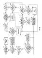
- FIG. 6is a network diagram detailing some of the functioning of one embodiment of the invention.
- FIG. 7is a network diagram showing a blown up view of a portion of FIG. 6 and detailing some of the functioning of one embodiment of the invention.
- FIG. 8is a network diagram detailing some of the functioning of one embodiment of the invention.
- FIG. 9is a flow chart detailing some of the functioning of the invention.
- FIG. 9 ais a flow chart detailing some of the functioning of the invention.
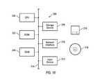
- FIG. 10is a schematic diagram showing an example of some of the components of a switch in accordance with the invention along with an example of recording media.
- RLDPRemote Loop Detection Protocol
- the RLDPis a port-VLAN oriented protocol or program used to detect loops in a network 100 .
- the RLDPmay be run out of every port in every VLAN coupled to another network.
- the protocolis light and should not cause high CPU utilization.
- core network 102may be running a first instance of a STP while the connected networks may be running a different instance or no instance.
- the RLDPallows for any switch in network 100 to remotely monitor any network connected to its ports. Upon detection of a loop in the remote network, the RLDP takes administrative action (discussed below) to block ports connected to the remote network with the loop.
- RLDPis enabled in switches 104 , 106 and 108 but not necessarily in switch 107 .
- core network 102is shown directly coupled to customer networks 110 , 112 , 114 , 116 and 118 , clearly these networks may also be indirectly communicably coupled through other intervening networks.
- networks 110 , 112 , 114 , 116 and 118may choose to run RLDP in switches 124 , 126 , 128 , 130 , 132 , 134 and 136 respectively.
- RLDPRLDP
- Switch 104is shown in a blow up 120 in FIG. 6 illustrating the presence of the RLDP software module 122 which is included in switch 104 , switch 106 and switch 108 .
- the RLDP programmay be stored in switch 104 or may be stored remotely and accessed by switch 104 .
- switch 104when a loop is detected in a particular one of customer networks 110 , 112 , 114 , 116 or 118 , that particular customer network is isolated from core network 102 while the remaining customer networks may remain connected to core network 102 .
- the RLDP packetsWhen the RLDP is enabled on a port of a switch, that port generates RLDP packets which are sent out at a constant interval—for example 0.1 seconds—which may be changed by the operator.
- the RLDP packetsinclude unique information discussed below.
- the packetsare L2 multicast packets with a MAC address of 0x030480000102.
- the packetsare sent from ports in a VLAN where the RLDP is enabled and follow the tag mode of the particular port. If the port is tagged to a VLAN, an IEEE 802.1Q tag is added to the packet between the Media Control Access (“MAC”) address and the data portion of the packet.
- MACMedia Control Access
- Protocol Identifier2 bytes. This is encoded in the first two octets of the RLDP packet and takes the value of “1”. Protocol Version—1 byte. This is encoded in the third octet and takes the value of “0”. VLAN Identifier—2 bytes. This is encoded in the fourth and fifth octet and takes the value of the VLAN where the RLDP packet originated. Bridge identifier—6 bytes. This is encoded in octets 6 through 11. It represents the bridge identification which should be unique. The first MAC address of the bridge may be used. Port Identifier—2 bytes. This is encoded in the twelfth and thirteenth octet. It includes the port ID in the system and should be a unique number within the bridge. The SNMP (Simple Network Management Protocol) interface ID may be used.
- SNMPSimple Network Management Protocol
- the RLDPdetermines whether the bridge identifier and port identifier of the received packet corresponds to the bridge/switch which received the received packet. If the identifiers do match, the RLDP has detected a loop in remote network 118 and action is taken to isolate that loop and the network. In order for a match to occur, the RLDP packet would have to originate in the receiving bridge, travel in a loop, and the then return to the receiving bridge. As network 102 has a blocked path, the loop must be in the customer network 118 attached to it.
- the action taken by the RLDPincludes blocking a data path either on the port 144 sending the RLDP packet or the port 142 that received the RLDP packet.
- the default optionis that the RLDP will block the port that receives the RLDP packets. Such a situation is shown in FIG. 7 . However, as shown in FIG. 8 , sometimes blocking the receiving port is not desirable as such blocking may impact all of network 102 . In this situation, the sending port 146 of bridge 106 is blocked.
- each network administratordecides, based on the architecture of the network, which ports to be blocked when a loop is found.
- a different procedureis used.
- both ports 104 a and 104 bare sending out RLDP packets, if a loop is detected in network 110 , both ports will receive these packets and will move to a blocking state.
- the RLDPdetermines whether the port which received the packet is different from the port which sent the packet. If they are the not different, then the sending/receiving port is blocked.
- the receiving porthas a lower port ID than the sending port, then the receiving port is blocked. Otherwise, the sending port is blocked.
- the port with a higher IDcould be blocked or any other method used which ensures that one port is blocked even if more than one port receives a RLDP packet indicating a loop.
- the RLDP softwarecontinues to send and receive RLDP packets on ports that are in the blocking state. No other data is received because the port is in a blocked state. However, the RLDP packets are still received so that the switch knows when the loop is fixed. Continuing with the example shown in FIG. 7 , if the RLDP packet corresponding to port 142 is no longer received on port 142 , it is likely that the loop is fixed. Thus, if a RLDP packet is not received in a known loop for a per port waiting time, port 142 changed from blocking to forwarding.
- the per port waiting timecan be configured and its default value is 10 seconds.
- step S 2the RLDP software queries whether it is time to send a RLDP packet. If it is time, the packet is sent at step S 3 and control branches to Step S 5 . If not, control still branches to step S 5 where the RLDP software queries whether a RLDP packet has been received. If such a packet has been received, control branches to step S 4 . If not, control still branches to step S 24 where the RLDP software queries whether any port is blocked. If the answer is yes, the control branches to step S 26 . If the answer in step S 24 is no, control branches back to step S 1 .
- the RLDPdecodes the bridge identifier received in the packet.
- the RLDPdetermines whether the bridge identifier in the received RLDP packet matches the bridge identifier of the particular bridge. If the identifiers do not match, the frame in the RLDP packet is flooded to the applicable ports in the VLAN in step S 14 and control branches back to step S 1 . If the bridge identifiers do match, control branch to step S 8 where the VLAN and port IDs are decoded from the received RLDP packet.
- step S 24where the RLDP determines whether any port is blocked. If no port is blocked, control branches back to step S 1 . If a port is blocked, control branches to step S 26 where the RLDP queries whether the current time minus the last time a RLDP packet was received is greater than or equal to the per port waiting time for the blocked port. If the answer is no, control branches to step S 1 . If the answer is yes, control branches to step S 28 and the blocking port is set to a forwarding port and then control branches back to step S 1 .
- step S 16there is shown another flow chart summarizing some of the features of the invention.
- the RLDPmay include steps S 11 and S 15 as shown in FIG. 9A .
- steps S 5 , S 4 , S 6 , S 8 and S 10as discussed above. If the answer to the query in step S 10 is yes, control branches to step S 11 where the RLDP determines whether the RLDP program is running on the received port. If the answer at step S 11 is no, control branches to step S 16 as discussed above.
- step S 15the RLDP queries whether the receiving port ID is less than or equal to the sending port ID. If the answer is yes, control branches to step S 19 as discussed above. If the answer is no, control branches to step S 21 as discussed above.
- the decision made in step S 15could be effectuated using the port with a higher ID or any other method which ensures that one port is blocked even if more than one port receives a RLDP packet indicating a loop. Whatever method is chosen, such method will override any customer configuration.
- each switchmay comprise a conventional computer 206 including a CPU 200 , a read only memory (“ROM”) 202 , a random access memory (“RAM”) 204 , a storage device 208 , a network interface (such as the ports discussed above) 210 and an input device 212 all coupled together by a bus 214 .
- the RLDP programmay be stored on computer 206 , on storage media 216 or stored remotely.
Landscapes
- Engineering & Computer Science (AREA)
- Computer Networks & Wireless Communication (AREA)
- Signal Processing (AREA)
- Small-Scale Networks (AREA)
Abstract
Description
| Protocol Identifier—2 bytes. This is encoded in the first two | ||
| octets of the RLDP packet and takes the value of “1”. | ||
| Protocol Version—1 byte. This is encoded in the third octet | ||
| and takes the value of “0”. | ||
| VLAN Identifier—2 bytes. This is encoded in the fourth and | ||
| fifth octet and takes the value of the VLAN where the RLDP packet | ||
| originated. | ||
| Bridge identifier—6 bytes. This is encoded in | ||
| 11. It represents the bridge identification which should be unique. | ||
| The first MAC address of the bridge may be used. | ||
| Port Identifier—2 bytes. This is encoded in the twelfth and | ||
| thirteenth octet. It includes the port ID in the system and should | ||
| be a unique number within the bridge. The SNMP (Simple Network | ||
| Management Protocol) interface ID may be used. | ||
Claims (22)
Priority Applications (1)
| Application Number | Priority Date | Filing Date | Title |
|---|---|---|---|
| US13/090,118US8446819B2 (en) | 2003-08-01 | 2011-04-19 | System and method for detecting and isolating a remote loop |
Applications Claiming Priority (3)
| Application Number | Priority Date | Filing Date | Title |
|---|---|---|---|
| US10/632,591US7558205B1 (en) | 2003-08-01 | 2003-08-01 | System and method for detecting and isolating a remote loop |
| US12/466,363US7944816B2 (en) | 2003-08-01 | 2009-05-14 | System and method for detecting and isolating a remote loop |
| US13/090,118US8446819B2 (en) | 2003-08-01 | 2011-04-19 | System and method for detecting and isolating a remote loop |
Related Parent Applications (1)
| Application Number | Title | Priority Date | Filing Date |
|---|---|---|---|
| US12/466,363ContinuationUS7944816B2 (en) | 2003-08-01 | 2009-05-14 | System and method for detecting and isolating a remote loop |
Publications (2)
| Publication Number | Publication Date |
|---|---|
| US20120106361A1 US20120106361A1 (en) | 2012-05-03 |
| US8446819B2true US8446819B2 (en) | 2013-05-21 |
Family
ID=40811055
Family Applications (3)
| Application Number | Title | Priority Date | Filing Date |
|---|---|---|---|
| US10/632,591Active2025-12-08US7558205B1 (en) | 2003-08-01 | 2003-08-01 | System and method for detecting and isolating a remote loop |
| US12/466,363Expired - Fee RelatedUS7944816B2 (en) | 2003-08-01 | 2009-05-14 | System and method for detecting and isolating a remote loop |
| US13/090,118Expired - Fee RelatedUS8446819B2 (en) | 2003-08-01 | 2011-04-19 | System and method for detecting and isolating a remote loop |
Family Applications Before (2)
| Application Number | Title | Priority Date | Filing Date |
|---|---|---|---|
| US10/632,591Active2025-12-08US7558205B1 (en) | 2003-08-01 | 2003-08-01 | System and method for detecting and isolating a remote loop |
| US12/466,363Expired - Fee RelatedUS7944816B2 (en) | 2003-08-01 | 2009-05-14 | System and method for detecting and isolating a remote loop |
Country Status (1)
| Country | Link |
|---|---|
| US (3) | US7558205B1 (en) |
Families Citing this family (20)
| Publication number | Priority date | Publication date | Assignee | Title |
|---|---|---|---|---|
| US7627654B2 (en) | 2003-06-09 | 2009-12-01 | Foundry Networks, Inc. | System and method for multiple spanning tree protocol domains in a virtual local area network |
| US7558205B1 (en) | 2003-08-01 | 2009-07-07 | Foundry Networks, Inc. | System and method for detecting and isolating a remote loop |
| US7564858B1 (en)* | 2003-08-01 | 2009-07-21 | Foundry Networks, Inc. | System and method for enabling a remote instance of a loop avoidance protocol |
| JP4397292B2 (en)* | 2004-07-09 | 2010-01-13 | 富士通株式会社 | Control packet loop prevention method and bridge device using the same |
| CN101128041B (en)* | 2006-08-15 | 2010-05-12 | 华为技术有限公司 | Method and system for processing failure of downlink data tunnel between access network and core network |
| JP4848254B2 (en)* | 2006-11-29 | 2011-12-28 | アラクサラネットワークス株式会社 | Devices that make up a ring network |
| JP2008278337A (en)* | 2007-05-01 | 2008-11-13 | Brother Ind Ltd | Information distribution system, terminal device and program used in the system, and circulation connection avoidance method |
| CN101534232B (en)* | 2008-03-10 | 2012-12-19 | 中兴通讯股份有限公司 | Method for preventing internet storm occurring in Ether multi-ring network |
| US8203932B2 (en)* | 2008-12-02 | 2012-06-19 | Electronics And Telecommunications Research Institute | Method and system for protection switching in ethernet ring |
| CN101674206B (en)* | 2009-10-20 | 2015-06-03 | 中兴通讯股份有限公司 | Loop detection method and network equipment |
| US8547877B2 (en)* | 2010-03-30 | 2013-10-01 | Telefonaktiebolaget L M Ericsson (Publ) | RSTP tracking |
| CN102340434B (en)* | 2011-07-07 | 2014-03-26 | 杭州华三通信技术有限公司 | Multihoming access-based loop avoidance method and edge devices |
| US9780964B1 (en) | 2012-01-23 | 2017-10-03 | Cisco Technology, Inc. | System and method for ring protection switching over adaptive modulation microwave links |
| US9444641B2 (en) | 2012-09-05 | 2016-09-13 | Brocade Communications Systems, Inc. | MAC flush optimizations for ethernet rings |
| US9148346B2 (en) | 2012-09-05 | 2015-09-29 | Brocade Communications Systems, Inc. | Multiple ring identification and configuration protocol |
| US9338060B2 (en) | 2012-09-05 | 2016-05-10 | Brocade Communications Systems, Inc. | Multiple ring identification and configuration protocol |
| US9161259B2 (en)* | 2013-03-20 | 2015-10-13 | Cisco Technology, Inc. | System and method for layer 3 ring protection with adaptive bandwidth microwave links in a network environment |
| US9392526B2 (en) | 2013-05-28 | 2016-07-12 | Cisco Technology, Inc. | Protection against fading in a network ring |
| CN105704020B (en)* | 2014-11-25 | 2019-05-17 | 华为技术有限公司 | Loop prevention method, equipment and system |
| US11477116B2 (en)* | 2020-08-20 | 2022-10-18 | Nokia Solutions And Networks Oy | Loop detection in ethernet packets |
Citations (45)
| Publication number | Priority date | Publication date | Assignee | Title |
|---|---|---|---|---|
| US5761435A (en) | 1994-03-17 | 1998-06-02 | Hitachi, Ltd. | Multiprocessor bridge having storage for spanning tree operation mode information indicating whether each port of the bridge is operable under spanning tree protocol |
| US5878232A (en) | 1996-12-27 | 1999-03-02 | Compaq Computer Corporation | Dynamic reconfiguration of network device's virtual LANs using the root identifiers and root ports determined by a spanning tree procedure |
| US5959968A (en) | 1997-07-30 | 1999-09-28 | Cisco Systems, Inc. | Port aggregation protocol |
| US5995486A (en) | 1994-09-17 | 1999-11-30 | International Business Machines Corporation | Flow control method and apparatus for cell-based communication networks |
| US6202114B1 (en) | 1997-12-31 | 2001-03-13 | Cisco Technology, Inc. | Spanning tree with fast link-failure convergence |
| US6204114B1 (en) | 1997-06-19 | 2001-03-20 | Micron Technology, Inc. | Method of making high density semiconductor memory |
| US6262977B1 (en) | 1998-08-28 | 2001-07-17 | 3Com Corporation | High availability spanning tree with rapid reconfiguration |
| US6282589B1 (en) | 1998-07-30 | 2001-08-28 | Micron Technology, Inc. | System for sharing data buffers from a buffer pool |
| US6304575B1 (en) | 1998-08-31 | 2001-10-16 | Cisco Technology, Inc. | Token ring spanning tree protocol |
| US20020154606A1 (en) | 2001-02-19 | 2002-10-24 | Duncan Robert James | Network management apparatus and method for determining the topology of a network |
| US20020159398A1 (en) | 2001-04-27 | 2002-10-31 | Masataka Yamada | Spanning tree control unit in the case of trouble or increase and method thereof |
| US20020181413A1 (en) | 2001-05-30 | 2002-12-05 | Nec Corporation | Communication apparatus, communication system, and communication control method |
| US20030142680A1 (en) | 2002-01-28 | 2003-07-31 | Naoki Oguchi | Device, network, and system for forwarding frames between geographically dispersed user networks |
| US20030169694A1 (en) | 2002-03-07 | 2003-09-11 | Seaman Michael John | Use of alternate ports in spanning tree configured bridged virtual local area networks |
| US6628624B1 (en) | 1998-12-09 | 2003-09-30 | Cisco Technology, Inc. | Value-added features for the spanning tree protocol |
| US6628661B1 (en) | 1998-08-27 | 2003-09-30 | Intel Corporation | Spanning tree recovery in computer networks |
| US6658004B1 (en) | 1999-12-28 | 2003-12-02 | Sun Microsystems, Inc. | Use of beacon message in a network for classifying and discarding messages |
| US20030223379A1 (en) | 2002-05-28 | 2003-12-04 | Xuguang Yang | Method and system for inter-domain loop protection using a hierarchy of loop resolving protocols |
| US20030223442A1 (en) | 2002-05-29 | 2003-12-04 | Huang Anguo T. | Buffer memory reservation |
| US6697339B1 (en) | 1999-03-04 | 2004-02-24 | 3Com Corporation | High availability spanning tree with rapid reconfiguration with alternate port selection |
| US6717922B2 (en) | 2002-03-04 | 2004-04-06 | Foundry Networks, Inc. | Network configuration protocol and method for rapid traffic recovery and loop avoidance in ring topologies |
| US20040081171A1 (en) | 2002-10-24 | 2004-04-29 | Finn Norman W. | Large-scale layer 2 metropolitan area network |
| US6766482B1 (en) | 2001-10-31 | 2004-07-20 | Extreme Networks | Ethernet automatic protection switching |
| US6795403B1 (en) | 2000-03-31 | 2004-09-21 | Cisco Technology, Inc. | Automatic discovery of switch devices in a network |
| US6801506B1 (en) | 1999-03-31 | 2004-10-05 | Cisco Technology, Inc. | Method and apparatus for providing fast spanning tree re-starts |
| US6813250B1 (en) | 1997-12-23 | 2004-11-02 | Cisco Technology, Inc. | Shared spanning tree protocol |
| US20040255050A1 (en) | 2002-01-22 | 2004-12-16 | Tsuyoshi Takehiro | Spanning tree bypassing method and apparatus |
| US20050013260A1 (en) | 2003-06-09 | 2005-01-20 | Foundry Networks, Inc. | System and method for multiple spanning tree protocol domains in a virtual local area network |
| US6898189B1 (en) | 2000-08-23 | 2005-05-24 | Cisco Technology, Inc. | Restartable spanning tree for high availability network systems |
| US6937576B1 (en) | 2000-10-17 | 2005-08-30 | Cisco Technology, Inc. | Multiple instance spanning tree protocol |
| US6985449B2 (en) | 2000-03-17 | 2006-01-10 | Anritsu Corporation | Apparatus and method for configuring spanning tree and spanning tree protocol system and bridge system |
| US20060206656A1 (en) | 2000-12-22 | 2006-09-14 | Marco Di Benedetto | Apparatus and method for preventing loops in a computer network |
| US20060233186A1 (en) | 2001-12-07 | 2006-10-19 | Maurizio Portolani | Spanning tree loop guard |
| US7154861B1 (en) | 2002-04-22 | 2006-12-26 | Extreme Networks | Method and system for a virtual local area network to span multiple loop free network topology domains |
| US7171504B2 (en) | 2001-10-03 | 2007-01-30 | Fujitsu Limited | Transmission unit |
| US7209435B1 (en) | 2002-04-16 | 2007-04-24 | Foundry Networks, Inc. | System and method for providing network route redundancy across Layer 2 devices |
| US7286491B1 (en) | 1999-03-01 | 2007-10-23 | Cisco Technology, Inc. | Virtual local area network membership registration protocol for multiple spanning tree network environments |
| US20080037428A1 (en) | 2001-12-17 | 2008-02-14 | Nation George W | Methods and structures for improved buffer management and dynamic adaptation of flow control status in high-speed communication networks |
| US7558205B1 (en) | 2003-08-01 | 2009-07-07 | Foundry Networks, Inc. | System and method for detecting and isolating a remote loop |
| US7564858B1 (en) | 2003-08-01 | 2009-07-21 | Foundry Networks, Inc. | System and method for enabling a remote instance of a loop avoidance protocol |
| US7586856B1 (en) | 2003-03-20 | 2009-09-08 | Foundry Networks, Inc. | Technical enhancements to STP (IEEE 802.1D) implementation |
| US7606229B1 (en) | 2002-11-08 | 2009-10-20 | Cisco Technology, Inc. | Generic bridge packet tunneling |
| US7620693B1 (en) | 2004-03-29 | 2009-11-17 | Sun Microsystems, Inc. | System and method for tracking infiniband RDMA read responses |
| US20100195661A1 (en) | 2002-12-20 | 2010-08-05 | Foundry Networks, Inc. | Optimizations and Enhancements to the IEEE RSTP 802.1w Implementation |
| US7848264B1 (en) | 1997-12-24 | 2010-12-07 | Cisco Technology, Inc. | Method and apparatus for rapidly reconfiguring computer networks |
- 2003
- 2003-08-01USUS10/632,591patent/US7558205B1/enactiveActive
- 2009
- 2009-05-14USUS12/466,363patent/US7944816B2/ennot_activeExpired - Fee Related
- 2011
- 2011-04-19USUS13/090,118patent/US8446819B2/ennot_activeExpired - Fee Related
Patent Citations (55)
| Publication number | Priority date | Publication date | Assignee | Title |
|---|---|---|---|---|
| US5761435A (en) | 1994-03-17 | 1998-06-02 | Hitachi, Ltd. | Multiprocessor bridge having storage for spanning tree operation mode information indicating whether each port of the bridge is operable under spanning tree protocol |
| US5995486A (en) | 1994-09-17 | 1999-11-30 | International Business Machines Corporation | Flow control method and apparatus for cell-based communication networks |
| US5878232A (en) | 1996-12-27 | 1999-03-02 | Compaq Computer Corporation | Dynamic reconfiguration of network device's virtual LANs using the root identifiers and root ports determined by a spanning tree procedure |
| US6204114B1 (en) | 1997-06-19 | 2001-03-20 | Micron Technology, Inc. | Method of making high density semiconductor memory |
| US5959968A (en) | 1997-07-30 | 1999-09-28 | Cisco Systems, Inc. | Port aggregation protocol |
| US6163543A (en) | 1997-07-30 | 2000-12-19 | Cisco Technology, Inc. | Port aggregation protocol |
| US6813250B1 (en) | 1997-12-23 | 2004-11-02 | Cisco Technology, Inc. | Shared spanning tree protocol |
| US7848264B1 (en) | 1997-12-24 | 2010-12-07 | Cisco Technology, Inc. | Method and apparatus for rapidly reconfiguring computer networks |
| US6202114B1 (en) | 1997-12-31 | 2001-03-13 | Cisco Technology, Inc. | Spanning tree with fast link-failure convergence |
| US6282589B1 (en) | 1998-07-30 | 2001-08-28 | Micron Technology, Inc. | System for sharing data buffers from a buffer pool |
| US6628661B1 (en) | 1998-08-27 | 2003-09-30 | Intel Corporation | Spanning tree recovery in computer networks |
| US6262977B1 (en) | 1998-08-28 | 2001-07-17 | 3Com Corporation | High availability spanning tree with rapid reconfiguration |
| US6304575B1 (en) | 1998-08-31 | 2001-10-16 | Cisco Technology, Inc. | Token ring spanning tree protocol |
| US6628624B1 (en) | 1998-12-09 | 2003-09-30 | Cisco Technology, Inc. | Value-added features for the spanning tree protocol |
| US7286491B1 (en) | 1999-03-01 | 2007-10-23 | Cisco Technology, Inc. | Virtual local area network membership registration protocol for multiple spanning tree network environments |
| US6697339B1 (en) | 1999-03-04 | 2004-02-24 | 3Com Corporation | High availability spanning tree with rapid reconfiguration with alternate port selection |
| US6801506B1 (en) | 1999-03-31 | 2004-10-05 | Cisco Technology, Inc. | Method and apparatus for providing fast spanning tree re-starts |
| US6658004B1 (en) | 1999-12-28 | 2003-12-02 | Sun Microsystems, Inc. | Use of beacon message in a network for classifying and discarding messages |
| US6985449B2 (en) | 2000-03-17 | 2006-01-10 | Anritsu Corporation | Apparatus and method for configuring spanning tree and spanning tree protocol system and bridge system |
| US6795403B1 (en) | 2000-03-31 | 2004-09-21 | Cisco Technology, Inc. | Automatic discovery of switch devices in a network |
| US7061858B1 (en) | 2000-08-23 | 2006-06-13 | Cisco Technology, Inc. | High availability architecture for network devices |
| US6898189B1 (en) | 2000-08-23 | 2005-05-24 | Cisco Technology, Inc. | Restartable spanning tree for high availability network systems |
| US6937576B1 (en) | 2000-10-17 | 2005-08-30 | Cisco Technology, Inc. | Multiple instance spanning tree protocol |
| US20050259597A1 (en) | 2000-10-17 | 2005-11-24 | Benedetto Marco D | Multiple instance spanning tree protocol |
| US20060206656A1 (en) | 2000-12-22 | 2006-09-14 | Marco Di Benedetto | Apparatus and method for preventing loops in a computer network |
| US20020154606A1 (en) | 2001-02-19 | 2002-10-24 | Duncan Robert James | Network management apparatus and method for determining the topology of a network |
| US20020159398A1 (en) | 2001-04-27 | 2002-10-31 | Masataka Yamada | Spanning tree control unit in the case of trouble or increase and method thereof |
| US20020181413A1 (en) | 2001-05-30 | 2002-12-05 | Nec Corporation | Communication apparatus, communication system, and communication control method |
| US7171504B2 (en) | 2001-10-03 | 2007-01-30 | Fujitsu Limited | Transmission unit |
| US6766482B1 (en) | 2001-10-31 | 2004-07-20 | Extreme Networks | Ethernet automatic protection switching |
| US7003705B1 (en) | 2001-10-31 | 2006-02-21 | Extreme Networks, Inc. | Ethernet automatic protection switching |
| US20060233186A1 (en) | 2001-12-07 | 2006-10-19 | Maurizio Portolani | Spanning tree loop guard |
| US20080037428A1 (en) | 2001-12-17 | 2008-02-14 | Nation George W | Methods and structures for improved buffer management and dynamic adaptation of flow control status in high-speed communication networks |
| US20040255050A1 (en) | 2002-01-22 | 2004-12-16 | Tsuyoshi Takehiro | Spanning tree bypassing method and apparatus |
| US20030142680A1 (en) | 2002-01-28 | 2003-07-31 | Naoki Oguchi | Device, network, and system for forwarding frames between geographically dispersed user networks |
| US6717922B2 (en) | 2002-03-04 | 2004-04-06 | Foundry Networks, Inc. | Network configuration protocol and method for rapid traffic recovery and loop avoidance in ring topologies |
| US20030169694A1 (en) | 2002-03-07 | 2003-09-11 | Seaman Michael John | Use of alternate ports in spanning tree configured bridged virtual local area networks |
| US7209435B1 (en) | 2002-04-16 | 2007-04-24 | Foundry Networks, Inc. | System and method for providing network route redundancy across Layer 2 devices |
| US7154861B1 (en) | 2002-04-22 | 2006-12-26 | Extreme Networks | Method and system for a virtual local area network to span multiple loop free network topology domains |
| US7126923B1 (en) | 2002-05-28 | 2006-10-24 | Extreme Networks, Inc. | Method and system for inter-domain loop protection using a hierarchy of loop resolving protocols |
| US20030223379A1 (en) | 2002-05-28 | 2003-12-04 | Xuguang Yang | Method and system for inter-domain loop protection using a hierarchy of loop resolving protocols |
| US20030223442A1 (en) | 2002-05-29 | 2003-12-04 | Huang Anguo T. | Buffer memory reservation |
| US20040081171A1 (en) | 2002-10-24 | 2004-04-29 | Finn Norman W. | Large-scale layer 2 metropolitan area network |
| US7606229B1 (en) | 2002-11-08 | 2009-10-20 | Cisco Technology, Inc. | Generic bridge packet tunneling |
| US20100195661A1 (en) | 2002-12-20 | 2010-08-05 | Foundry Networks, Inc. | Optimizations and Enhancements to the IEEE RSTP 802.1w Implementation |
| US7586856B1 (en) | 2003-03-20 | 2009-09-08 | Foundry Networks, Inc. | Technical enhancements to STP (IEEE 802.1D) implementation |
| US7627654B2 (en) | 2003-06-09 | 2009-12-01 | Foundry Networks, Inc. | System and method for multiple spanning tree protocol domains in a virtual local area network |
| US20050013260A1 (en) | 2003-06-09 | 2005-01-20 | Foundry Networks, Inc. | System and method for multiple spanning tree protocol domains in a virtual local area network |
| US7856490B2 (en) | 2003-06-09 | 2010-12-21 | Foundry Networks, Llc | System and method for multiple spanning tree protocol domains in a virtual local area network |
| US20090225668A1 (en) | 2003-08-01 | 2009-09-10 | Jordi Moncada-Elias | System and Method For Detecting And Isolating A Remote Loop |
| US7564858B1 (en) | 2003-08-01 | 2009-07-21 | Foundry Networks, Inc. | System and method for enabling a remote instance of a loop avoidance protocol |
| US7822049B1 (en) | 2003-08-01 | 2010-10-26 | Foundry Networks, Llc | System and method for enabling a remote instance of a loop avoidance protocol |
| US7558205B1 (en) | 2003-08-01 | 2009-07-07 | Foundry Networks, Inc. | System and method for detecting and isolating a remote loop |
| US20110064001A1 (en) | 2003-08-01 | 2011-03-17 | Brocade Communications Systems, Inc. | System and method for enabling a remote instance of a loop avoidance protocol |
| US7620693B1 (en) | 2004-03-29 | 2009-11-17 | Sun Microsystems, Inc. | System and method for tracking infiniband RDMA read responses |
Non-Patent Citations (43)
| Title |
|---|
| Abdelhalim, A., "IP/MPLS-Based vs. Layer-2," Whitepaper, Mar. 22, 2002, 16 pages. |
| ANS/IEEE Std 802.id, 1998 Edition, "Part 3: Media Access Control (MAC) Bridges," Adopted by the ISO/IEC 15802-3:1998, Sponsor LAN/MAN Standards Committee of the IEEE Computer Society, 374 pages. |
| Cobb, J. A., "Convergent Multi-Path Routing," Whitepaper, International Conference on Network Protocols, 2000, 10 pages. |
| Definition of "to" from Answers.com, retrieved Jul. 28, 2011. |
| Definition of "to" from Dictionary.com, retrieved Jul. 28, 2011. |
| Definition of "to" from Merriam-Webster.com, retrieved Jul. 28, 2011. |
| Definition of "toward" from Answers.com, retrieved Jul. 28, 2011. |
| Definition of "toward" from Dictionary.com, retrieved Jul. 28, 2011. |
| Definition of "toward" from Merriam-Webster.com, retrieved Jul. 28, 2011. |
| Final Office Action in U.S. Appl. No. 10/632,635, mailed Mar. 17, 2008. |
| Finn, N., "Spanning the World With Ethernet," Powerpoint Presentation, 2001, 132 pages. |
| Notice of Allowance in U.S. Appl. No. 10/456,756, mailed Sep. 17, 2009. |
| Notice of Allowance in U.S. Appl. No. 10/632,591, mailed Apr. 30, 2009. |
| Notice of Allowance in U.S. Appl. No. 10/632,591, mailed Aug. 4, 2008. |
| Notice of Allowance in U.S. Appl. No. 10/632,591, mailed Jan. 12, 2009. |
| Notice of Allowance in U.S. Appl. No. 10/632,591, mailed Mar. 13, 2009. |
| Notice of Allowance in U.S. Appl. No. 10/632,635, mailed May 20, 2009. |
| Notice of Allowance in U.S. Appl. No. 11/246,945, mailed Sep. 2, 2010. |
| Notice of Allowance in U.S. Appl. No. 12/466,363, mailed Apr. 1, 2011. |
| Notice of Allowance in U.S. Appl. No. 12/580,230, mailed Oct. 6, 2010. |
| Notice of Allowance in U.S. Appl. No. 12/878,973, mailed Aug. 31, 2012. |
| Office Action in U.S. Appl. No. 10/456,756, mailed Jan. 27, 2009. |
| Office Action in U.S. Appl. No. 10/456,756, mailed Jul. 20, 2009. |
| Office Action in U.S. Appl. No. 10/456,756, mailed Mar. 21, 2007. |
| Office Action in U.S. Appl. No. 10/456,756, mailed May 7, 2008. |
| Office Action in U.S. Appl. No. 10/456,756, mailed Oct. 18, 2007. |
| Office Action in U.S. Appl. No. 10/632,591, mailed Jun. 26, 2007. |
| Office Action in U.S. Appl. No. 10/632,591, mailed Mar. 5, 2008. |
| Office Action in U.S. Appl. No. 10/632,635, mailed Dec. 3, 2008. |
| Office Action in U.S. Appl. No. 10/632,635, mailed Sep. 19, 2007. |
| Office Action in U.S. Appl. No. 11/246,945, mailed Dec. 30, 2008. |
| Office Action in U.S. Appl. No. 11/246,945, mailed Jul. 7, 2009. |
| Office Action in U.S. Appl. No. 11/246,945, mailed Jun. 30, 2008. |
| Office Action in U.S. Appl. No. 11/246,945, mailed Mar. 30, 2010. |
| Office Action in U.S. Appl. No. 12/466,363, mailed Dec. 15, 2010. |
| Office Action in U.S. Appl. No. 12/466,363, mailed Sep. 22, 2010. |
| Office Action in U.S. Appl. No. 12/580,230, mailed Aug. 19, 2010. |
| Office Action in U.S. Appl. No. 12/878,973, mailed Jul. 6, 2011. |
| Office Action in U.S. Appl. No. 12/878,973, mailed Mar. 8, 2012. |
| Office Action in U.S. Appl. No. 12/878,973, mailed Oct. 26, 2011. |
| Office Action in U.S. Appl. No. 12/939,115, mailed Aug. 17, 2012. |
| Supplemental Notice of Allowance in U.S. Appl. No. 12/580,230, mailed Nov. 1, 2010. |
| U.S. Appl. No. 12/939,115, filed Nov. 3, 2010. |
Also Published As
| Publication number | Publication date |
|---|---|
| US20120106361A1 (en) | 2012-05-03 |
| US20090225668A1 (en) | 2009-09-10 |
| US7558205B1 (en) | 2009-07-07 |
| US7944816B2 (en) | 2011-05-17 |
Similar Documents
| Publication | Publication Date | Title |
|---|---|---|
| US8446819B2 (en) | System and method for detecting and isolating a remote loop | |
| US8345699B2 (en) | System and method for enabling a remote instance of a loop avoidance protocol | |
| US7606177B1 (en) | Value-added features for the spanning tree protocol | |
| US7233991B2 (en) | Self-healing tree network | |
| US7869439B1 (en) | Varying packet switch behavior based on a quantity of virtual interfaces associated with a virtual switch | |
| US9019840B2 (en) | CFM for conflicting MAC address notification | |
| US7848264B1 (en) | Method and apparatus for rapidly reconfiguring computer networks | |
| US7397811B2 (en) | Method and apparatus for determining shared broadcast domains of network switches, ports and interfaces | |
| US7428237B1 (en) | Fast convergence with topology switching | |
| US7440397B2 (en) | Protection that automatic and speedily restore of Ethernet ring network | |
| JP4020753B2 (en) | Ring switching method | |
| CN102461087B (en) | Preventing loss of network traffic due to inconsistent configuration within the network | |
| EP2643940B1 (en) | Method of shrinking a data loss window in a packet network device | |
| US7606939B1 (en) | Scaling private virtual local area networks (VLANs) across large metropolitan area networks (MANs). | |
| EP4125244A1 (en) | Hash-based multi-homing | |
| US20100226244A1 (en) | Network System | |
| US20100135162A1 (en) | Transmission apparatus and transmission system | |
| US20080002570A1 (en) | Network redundancy method, and middle apparatus and upper apparatus for the network redundancy method | |
| KR20060048725A (en) | Method and apparatus for providing fast end-to-end recovery in packet switch communication network | |
| EP2078381A1 (en) | Method of detecting transport leaks in hybrid switching networks | |
| US7843854B2 (en) | Network loop detection using known static addresses | |
| US12432089B2 (en) | Identifying source of layer-2 loop in ring network | |
| Cisco | Cisco IOS Commands | |
| Huynh et al. | RRR: Rapid ring recovery submillisecond decentralized recovery for ethernet ring | |
| US20250141774A1 (en) | Tracing the path of a loop in a network |
Legal Events
| Date | Code | Title | Description |
|---|---|---|---|
| AS | Assignment | Owner name:FOUNDRY NETWORKS, INC., CALIFORNIA Free format text:ASSIGNMENT OF ASSIGNORS INTEREST;ASSIGNORS:MONCADA-ELIAS, JORDI;RAMANATHAN, RAJIV;REEL/FRAME:026264/0618 Effective date:20030801 | |
| AS | Assignment | Owner name:BANK OF AMERICA, N.A., AS ADMINISTRATIVE AGENT, CA Free format text:SUPPLEMENTAL PATENT SECURITY AGREEMENT;ASSIGNORS:BROCADE COMMUNICATIONS SYSTEMS, INC.;FOUNDRY NETWORKS, LLC;MCDATA CORPORATION;REEL/FRAME:026938/0922 Effective date:20110916 | |
| AS | Assignment | Owner name:WELLS FARGO BANK, NATIONAL ASSOCIATION, AS COLLATE Free format text:SUPPLEMENTAL PATENT SECURITY AGREEMENT;ASSIGNORS:BROCADE COMMUNICATIONS SYSTEMS, INC.;FOUNDRY NETWORKS, LLC;INRANGE TECHNOLOGIES CORPORATION;AND OTHERS;REEL/FRAME:026971/0042 Effective date:20110916 | |
| AS | Assignment | Owner name:FOUNDRY NETWORKS, LLC, CALIFORNIA Free format text:CHANGE OF NAME;ASSIGNOR:FOUNDRY NETWORKS, INC.;REEL/FRAME:027840/0249 Effective date:20090511 | |
| STCF | Information on status: patent grant | Free format text:PATENTED CASE | |
| FEPP | Fee payment procedure | Free format text:PAYOR NUMBER ASSIGNED (ORIGINAL EVENT CODE: ASPN); ENTITY STATUS OF PATENT OWNER: LARGE ENTITY | |
| AS | Assignment | Owner name:FOUNDRY NETWORKS, LLC, CALIFORNIA Free format text:RELEASE BY SECURED PARTY;ASSIGNOR:BANK OF AMERICA, N.A., AS ADMINISTRATIVE AGENT;REEL/FRAME:034784/0609 Effective date:20150114 Owner name:BROCADE COMMUNICATIONS SYSTEMS, INC., CALIFORNIA Free format text:RELEASE BY SECURED PARTY;ASSIGNOR:BANK OF AMERICA, N.A., AS ADMINISTRATIVE AGENT;REEL/FRAME:034784/0609 Effective date:20150114 | |
| AS | Assignment | Owner name:BROCADE COMMUNICATIONS SYSTEMS, INC., CALIFORNIA Free format text:RELEASE BY SECURED PARTY;ASSIGNOR:WELLS FARGO BANK, NATIONAL ASSOCIATION, AS COLLATERAL AGENT;REEL/FRAME:034804/0793 Effective date:20150114 Owner name:FOUNDRY NETWORKS, LLC, CALIFORNIA Free format text:RELEASE BY SECURED PARTY;ASSIGNOR:WELLS FARGO BANK, NATIONAL ASSOCIATION, AS COLLATERAL AGENT;REEL/FRAME:034804/0793 Effective date:20150114 | |
| FPAY | Fee payment | Year of fee payment:4 | |
| AS | Assignment | Owner name:AVAGO TECHNOLOGIES INTERNATIONAL SALES PTE. LIMITED, SINGAPORE Free format text:ASSIGNMENT OF ASSIGNORS INTEREST;ASSIGNOR:BROCADE COMMUNICATIONS SYSTEMS LLC;REEL/FRAME:047270/0247 Effective date:20180905 Owner name:AVAGO TECHNOLOGIES INTERNATIONAL SALES PTE. LIMITE Free format text:ASSIGNMENT OF ASSIGNORS INTEREST;ASSIGNOR:BROCADE COMMUNICATIONS SYSTEMS LLC;REEL/FRAME:047270/0247 Effective date:20180905 | |
| FEPP | Fee payment procedure | Free format text:MAINTENANCE FEE REMINDER MAILED (ORIGINAL EVENT CODE: REM.); ENTITY STATUS OF PATENT OWNER: LARGE ENTITY | |
| LAPS | Lapse for failure to pay maintenance fees | Free format text:PATENT EXPIRED FOR FAILURE TO PAY MAINTENANCE FEES (ORIGINAL EVENT CODE: EXP.); ENTITY STATUS OF PATENT OWNER: LARGE ENTITY | |
| STCH | Information on status: patent discontinuation | Free format text:PATENT EXPIRED DUE TO NONPAYMENT OF MAINTENANCE FEES UNDER 37 CFR 1.362 | |
| FP | Lapsed due to failure to pay maintenance fee | Effective date:20210521 |