US8446685B2 - Servo frame interval correction apparatus, storage apparatus and servo frame interval correction method - Google Patents
Servo frame interval correction apparatus, storage apparatus and servo frame interval correction methodDownload PDFInfo
- Publication number
- US8446685B2 US8446685B2US12/212,310US21231008AUS8446685B2US 8446685 B2US8446685 B2US 8446685B2US 21231008 AUS21231008 AUS 21231008AUS 8446685 B2US8446685 B2US 8446685B2
- Authority
- US
- United States
- Prior art keywords
- servo frame
- detection time
- time interval
- unit
- interval
- Prior art date
- Legal status (The legal status is an assumption and is not a legal conclusion. Google has not performed a legal analysis and makes no representation as to the accuracy of the status listed.)
- Active, expires
Links
Images


Classifications
- G—PHYSICS
- G11—INFORMATION STORAGE
- G11B—INFORMATION STORAGE BASED ON RELATIVE MOVEMENT BETWEEN RECORD CARRIER AND TRANSDUCER
- G11B21/00—Head arrangements not specific to the method of recording or reproducing
- G11B21/02—Driving or moving of heads
- G11B21/10—Track finding or aligning by moving the head ; Provisions for maintaining alignment of the head relative to the track during transducing operation, i.e. track following
- G—PHYSICS
- G11—INFORMATION STORAGE
- G11B—INFORMATION STORAGE BASED ON RELATIVE MOVEMENT BETWEEN RECORD CARRIER AND TRANSDUCER
- G11B5/00—Recording by magnetisation or demagnetisation of a record carrier; Reproducing by magnetic means; Record carriers therefor
- G11B5/48—Disposition or mounting of heads or head supports relative to record carriers ; arrangements of heads, e.g. for scanning the record carrier to increase the relative speed
- G11B5/58—Disposition or mounting of heads or head supports relative to record carriers ; arrangements of heads, e.g. for scanning the record carrier to increase the relative speed with provision for moving the head for the purpose of maintaining alignment of the head relative to the record carrier during transducing operation, e.g. to compensate for surface irregularities of the latter or for track following
- G11B5/596—Disposition or mounting of heads or head supports relative to record carriers ; arrangements of heads, e.g. for scanning the record carrier to increase the relative speed with provision for moving the head for the purpose of maintaining alignment of the head relative to the record carrier during transducing operation, e.g. to compensate for surface irregularities of the latter or for track following for track following on disks
- G11B5/59633—Servo formatting
- G11B5/59655—Sector, sample or burst servo format
- G—PHYSICS
- G11—INFORMATION STORAGE
- G11B—INFORMATION STORAGE BASED ON RELATIVE MOVEMENT BETWEEN RECORD CARRIER AND TRANSDUCER
- G11B21/00—Head arrangements not specific to the method of recording or reproducing
- G11B21/02—Driving or moving of heads
Definitions
- the embodiment discussed hereinare directed to a servo frame interval correction method in a storage apparatus for correcting intervals between servo frames formed on a recording medium having a deviation from the center of rotation.
- a magnetic head positioning control method controlled by a conventional magnetic disk drivewill be disclosed with reference to FIG. 1 .
- a manipulated variable u 101is input to an actual mechanics 102 as a driving electric power value of a power amplifier for a voice coil motor. Then, a demodulated position 103 is an actual position of the servo frame read with the magnetic moved by the actual mechanics 102 .
- the magnetic disk drivecalculates a position and velocity of a subsequent servo frame by adding a control matrix Z ⁇ 1 to a present position of the magnetic head (calculated position 104 ), to a present velocity of the magnetic head (calculated velocity 105 ), and to a calculated external force 106 , which is a bias component, respectively.
- the control matrix Z ⁇ 1will be described in detail later.
- the magnetic disk drivecalculates a differential between the calculated position 104 and the demodulated position 103 as an estimation error 107 .
- the estimation error 107is added to a coefficient of the calculated position Lp, a coefficient of the calculated velocity Lv, and a coefficient of the calculated external force Lb, respectively.
- the position of the servo frame to be detected subsequently(estimated position 108 ) is calculated by adding up a summation of the calculated error 107 and the coefficient Lp and a summation of the control matrix and the calculated position 104 .
- estimated velocity 109 on reaching the subsequent servo frame, and an estimated external force 110are calculated by the magnetic disk drive.
- a manipulated variable u 111is determined by adding up a summation of the estimated position 108 and a proportional term Kp, and a summation of the estimated velocity 109 and a derivative term Kv.
- the magnetic headis controlled according to the manipulated variable u 111 determined above.
- the estimated external force 110is not taken into consideration in the determination of the manipulated variable u because the estimated external force is processed outside of the PID control.
- the magnetic headis correctly positioned according to the manipulated variable u. Then, when the process to search for the subsequent servo frame switches, an estimated position and an estimated velocity of the subsequent servo frame are derived by substituting the estimated position for a calculated position, the estimated velocity for a calculated velocity, and the estimated external force for a calculated external force.
- a digital signal processormay detect a demodulated position and a current applied to a magnetic head incorporated in the magnetic disk drive via a power amplifier by the DSP. There are two calculations to obtain the velocity of the magnetic head: one is to obtain the velocity from a differential between positions; and the other is to obtain the velocity by integrating an acceleration based on the current. In modern control methods, the velocity is typically derived by integrating the acceleration.
- the control of the magnetic head position described aboveis designed on an assumption that servo frames are obtained at equal-spaced intervals.
- servo framesare infinitesimally deviated from the center of rotation due to a mismatch between the rotation centers of the SSTW and a magnetic disk drive in which a magnetic disk is incorporated.
- the magnetic headtraces an elliptic track, which causes the lengths of the servo frames to vary.
- the conventional control systemis designed with an assumption that position signals are detected at equal-spaced intervals.
- the intervals between the servo framesbecome irregular because of the elliptic track.
- the variation in the servo frame detection time intervalsis not a problem when seek velocity is slow.
- the variation in the servo frame detection time intervalsaffects seeking accuracy to a greater degree.
- the erroris 0.1% when converted to time. Where the head moves over 300 tracks, the error is 0.3 tracks, which is insignificant.
- the errorsare accumulated in the control system, positioning a target is difficult due to the positioning errors. As a result the seek time is increased which leads to reduced access times and a deterioration in the performance of the magnetic disk drive.
- the embodiment of the present inventionis disclosed to solve the problem mentioned above.
- an object of the embodimentis to provide a servo frame interval correction apparatus, a storage apparatus, and a servo frame interval correction method for correcting estimated positions (or calculated positions).
- a servo frame interval correction apparatusincludes a detection unit for detecting a first servo frame formed on said recording medium.
- the apparatusincludes an acquiring unit acquiring a detection time interval between said first servo frame and a second servo frame detected subsequently to the first servo frame from a table storing a detection time interval between a specific servo frame and a servo frame detected subsequently to the specific servo frame.
- the apparatusincludes a differential calculation unit calculating a differential between the detection time interval acquired by said acquiring unit and a reference time interval.
- the apparatusincludes and a correction unit correcting an estimated position of said second servo frame based on the differential calculated by said differential calculation unit.
- FIG. 1is a block diagram illustrating control function of the conventional magnetic disk drive
- FIG. 2illustrates an example of the block diagram of the magnetic disk drive
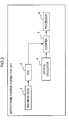
- FIG. 3is a block diagram illustrating the servo frame position correction unit
- FIG. 4illustrates an example of the block diagram illustrating the function of the magnetic disk drive
- FIG. 5shows equations 1 through 3 for servo frame position corrections calculated by the servo frame position correction unit
- FIG. 6shows equations 4 through 6 for servo frame position corrections calculated by the servo frame position correction unit
- FIG. 7shows equations 7 and 8 for servo frame position corrections calculated by the servo frame position correction unit
- FIG. 8is a flow chart illustrating an example of servo frame interval detection executed by the servo frame position correction unit.
- FIG. 9is a flow chart illustrating an example of a servo frame correction executed by the servo frame position correction unit.
- FIG. 2illustrates the block diagram of the control function of the magnetic disk drive according to the embodiment.
- a magnetic disk drive 1calculates the estimated position by adding a servo frame position correction amount 140 in FIG. 2 to the calculated position shown in FIG. 1 .
- the servo frame position correction amount 140is calculated by a servo frame position correction unit 100 included in the magnetic disk drive 1 .
- the structure of the servo frame position correction unit 100 for calculating a correction amount of a servo frame positionwill be disclosed with reference to the block diagram shown in FIG. 3 .
- the servo frame position correction unit 100has: a read channel (RDC) 3 for demodulating signals read with a magnetic head 2 to detect servo frames; a counter 5 for counting time at which the servo frames are detected according to frequencies oscillated by a crystal oscillator 4 as a count value; and a processor 6 for detecting intervals between the servo frames by subtracting a previous count value counted by the counter 5 from a count value counted next to the value.
- the processor 6calculates a correction amount of the servo frame position based on the detected servo frame interval.
- FIG. 4is the block diagram illustrating the function of the magnetic disk drive 1 .
- the magnetic disk drive 1has a detection unit 10 , an acquiring unit 11 , a differential calculation unit 12 , a correction unit 13 , a measuring unit 14 , a detection time interval calculation unit 15 , an update unit 16 , a servo frame interval table 20 , a recording medium 30 and a control unit 31 .
- the detection unit 10detects a first servo frame from the recording medium 30 on which multiple servo frames are arranged.
- the acquiring unit 11acquires the detection time interval between the first servo frame detected by the detection unit 10 and a second servo frame detected subsequently to the servo frame, from the servo frame interval table 20 .
- the differential calculation unit 12calculates a differential between the detection time interval acquired by the acquiring unit 11 and a specific pre-defined reference servo frame time (a reference time interval).
- the reference servo frame time intervalis defined with an assumption that the recording medium is not decentered and servo frames arranged thereon are detected at equal intervals.
- the correction unit 13corrects an estimated position, which is the position shown in FIG. 1 estimated by the conventional method, of the second servo frame based on the differential calculated by the differential calculation unit 12 .
- the measuring unit 14measures a detection time at which a servo frame is detected by the detection unit 10 .
- the detection time interval calculation unit 15calculates detection time intervals based on the detection time measured by the measuring unit 14 .
- the update unit 16updates the detection time interval stored in the servo frame interval table 20 to the detection time interval calculated by the detection time interval calculation unit 15 .
- the servo frame interval table 20stores a detection time interval between a specific servo frame and a servo frame detected subsequently to the specific servo frame, corresponding to an identification number of the servo frame.
- the recording medium 30is a thin discoidal medium in which data are recorded magnetically.
- the control unit 31controls the magnetic head to move to a position corrected by the correction unit 13 .
- the servo frame position correction unit 100 functionsare achieved through each of the functions of the detection unit 10 , the acquiring unit 11 , the differential calculation unit 12 , the correction unit 13 , the measuring unit 14 , the detection time interval calculation unit 15 , the update unit 16 , and the servo frame interval table 20 .
- Servo frame position correction calculated by the servo frame position correction unit 100will be disclosed with reference to FIGS. 5 through 7 .
- Pos (t)a position at time t
- Vel (t)velocity at time t
- Umanipulated variable or controlled variable based on an acceleration
- equation 2After an elapse of time Td/Ts, equation 2 is used.
- equation 3is used.
- the matrix on the right side and the first term of equation 3is a control matrix, and is labeled as Z ⁇ 1 in FIGS. 1 and 2 .
- All control matricesare designed in reference to the unit of sample time Ts.
- the following exampleconsiders how a control matrix changes when a servo frame interval (SFI) varies infinitesimally due to a decentering of a virtual circle (circle with eccentricity).
- SFIservo frame interval
- a correction of an SFI variation where 1 sample and ⁇ elapseis given by equation 4 shown in FIG. 6 .
- equation 5is commonly used as an approximation. Where the approximation expressed in equation 5 is substituted into equation 4, equation 6 is used.
- a position PosBar and velocity VelBar obtained from the control matrixmay be corrected by applying the correction calculation.
- ⁇ Uis infinitesimal, therefore, only a position is a factor in the calculation of a correction amount of the servo frame.
- the final correction amount of the servo frameis expressed by equation 8. Accordingly, the servo frame position may be corrected by adding a summation of the estimated velocity shown in FIGS. 1 and 9 and ⁇ t (SFI time).
- the detection unit 10which includes the magnetic head 2 and the RDC 3 , detects the servo frames from signals read from the recording medium 30 .
- the measuring unit 14which includes the crystal oscillator 4 and the counter 5 , measures the time, as count values, at which the servo frames are detected.
- the detection time interval calculation unit 15(processor 6 ) reads a present count value and subtracts a previous count value from the count value to detect a time interval of servo frames in operation S 1 .
- the update unit 16updates the servo frame time interval corresponding to an identification number of a servo frame that is currently processed and stored in the servo frame interval table 20 , to the servo frame time interval detected in operation S 1 .
- the servo frame position correction unit 100detects a decentering error more accurately.
- the acquiring unit 11acquires, in operation S 3 , the servo frame time interval, which is the detected time interval between the servo frame detected by detection unit 10 and the servo frame detected subsequently, corresponding to the servo frame number, which is currently being processed, detected by detection unit 10 .
- the differential calculation unit 12calculates, in operation S 4 , a differential ⁇ between the detected servo frame time interval and the pre-defined reference servo frame time interval.
- the correction unit 13calculates, in operation S 5 , a position correction amount of the servo frame by multiplying ⁇ by the estimated velocity. Then the correction amount calculated in operation S 5 is added to an estimated position in operation S 6 .
- control unit 31moves the detection unit 10 by PID control.
- the servo frame position correction unit 100is included in the magnetic disk drive 1 .
- the servo frame position correction unit 100may be provided as a servo frame interval correction apparatus for correcting servo frame positions.
Landscapes
- Moving Of The Head To Find And Align With The Track (AREA)
Abstract
Description
Claims (15)
Applications Claiming Priority (2)
| Application Number | Priority Date | Filing Date | Title |
|---|---|---|---|
| JP2007-253694 | 2007-09-28 | ||
| JP2007253694AJP4991469B2 (en) | 2007-09-28 | 2007-09-28 | Servo frame interval correction device, storage device, and servo frame interval correction method |
Publications (2)
| Publication Number | Publication Date |
|---|---|
| US20090086598A1 US20090086598A1 (en) | 2009-04-02 |
| US8446685B2true US8446685B2 (en) | 2013-05-21 |
Family
ID=40508137
Family Applications (1)
| Application Number | Title | Priority Date | Filing Date |
|---|---|---|---|
| US12/212,310Active2032-03-12US8446685B2 (en) | 2007-09-28 | 2008-09-17 | Servo frame interval correction apparatus, storage apparatus and servo frame interval correction method |
Country Status (3)
| Country | Link |
|---|---|
| US (1) | US8446685B2 (en) |
| JP (1) | JP4991469B2 (en) |
| KR (1) | KR20090033021A (en) |
Families Citing this family (2)
| Publication number | Priority date | Publication date | Assignee | Title |
|---|---|---|---|---|
| US8139312B2 (en)* | 2010-03-02 | 2012-03-20 | International Business Machines Corporation | Timing alternative intervals within a timing based servo band |
| JP2014182857A (en) | 2013-03-19 | 2014-09-29 | Toshiba Corp | Magnetic disk device, and control method of magnetic disk device |
Citations (13)
| Publication number | Priority date | Publication date | Assignee | Title |
|---|---|---|---|---|
| US5153788A (en)* | 1989-03-29 | 1992-10-06 | Mitsubishi Denki Kabushiki Kaisha | Method of recording and detecting servo information for positioning magnetic head |
| WO1996011470A1 (en) | 1994-10-11 | 1996-04-18 | Quantum Corporation | Synchronous detection of concurrent servo bursts for fine head position in disk drive |
| US5825568A (en)* | 1994-05-11 | 1998-10-20 | Samsung Electronics Co. Ltd. | Servo address mark detection compensating circuit |
| US5862005A (en) | 1994-10-11 | 1999-01-19 | Quantum Corporation | Synchronous detection of wide bi-phase coded servo information for disk drive |
| JPH11353831A (en) | 1998-06-10 | 1999-12-24 | Nec Ibaraki Ltd | Apparatus and method for positioning control of magnetic head, and recording medium with control program recorded |
| US6081397A (en)* | 1997-04-08 | 2000-06-27 | International Business Machines Corporation | Method and apparatus for SID-to-SID period estimation |
| US6115199A (en)* | 1996-04-30 | 2000-09-05 | Samsung Electronics Co., Ltd. | Circuit for preventing servo sector from being overwritten due to misdetection of a servo address mark in a magnetic disk |
| JP2003045129A (en) | 2001-08-02 | 2003-02-14 | Toshiba Corp | Disk storage device and servo sector pulse generation method in the device |
| JP2004139677A (en) | 2002-10-18 | 2004-05-13 | Fujitsu Ltd | Magnetic disk drive and recording position correction method |
| US20050286152A1 (en) | 2004-06-29 | 2005-12-29 | Hitachi Global Storage Technologies Netherlands B.V. | Magnetic disk device and read/write method |
| US7126776B1 (en)* | 2002-04-17 | 2006-10-24 | Western Digital Technologies, Inc. | Disk drive having a sector clock that is synchronized to the angular speed of the spindle motor |
| US7440211B2 (en)* | 2004-05-28 | 2008-10-21 | Samsung Electronics Co., Ltd. | Apparatus and/or method of controlling timing of servo pulses and disk drive using the method |
| US8174784B2 (en)* | 2007-10-30 | 2012-05-08 | Agere Systems Inc. | Systems and methods for inter-location control of storage access |
Family Cites Families (1)
| Publication number | Priority date | Publication date | Assignee | Title |
|---|---|---|---|---|
| JP2002245738A (en)* | 2001-02-15 | 2002-08-30 | Fujitsu Ltd | Disk device and disturbance compensation method |
- 2007
- 2007-09-28JPJP2007253694Apatent/JP4991469B2/ennot_activeExpired - Fee Related
- 2008
- 2008-09-17USUS12/212,310patent/US8446685B2/enactiveActive
- 2008-09-24KRKR1020080093546Apatent/KR20090033021A/ennot_activeCeased
Patent Citations (18)
| Publication number | Priority date | Publication date | Assignee | Title |
|---|---|---|---|---|
| US5153788A (en)* | 1989-03-29 | 1992-10-06 | Mitsubishi Denki Kabushiki Kaisha | Method of recording and detecting servo information for positioning magnetic head |
| US5825568A (en)* | 1994-05-11 | 1998-10-20 | Samsung Electronics Co. Ltd. | Servo address mark detection compensating circuit |
| WO1996011470A1 (en) | 1994-10-11 | 1996-04-18 | Quantum Corporation | Synchronous detection of concurrent servo bursts for fine head position in disk drive |
| US5576906A (en) | 1994-10-11 | 1996-11-19 | Quantum Corporation | Synchronous detection of concurrent servo bursts for fine head position in disk drive |
| JPH10507027A (en) | 1994-10-11 | 1998-07-07 | クウォンタム・コーポレイション | Synchronous detection of simultaneous servo bursts for fine head position in disk drives |
| US5862005A (en) | 1994-10-11 | 1999-01-19 | Quantum Corporation | Synchronous detection of wide bi-phase coded servo information for disk drive |
| US6452990B1 (en) | 1994-10-11 | 2002-09-17 | Maxtor Corporation | Synchronous detection of wide bi-phase coded servo information for disk drive |
| US6115199A (en)* | 1996-04-30 | 2000-09-05 | Samsung Electronics Co., Ltd. | Circuit for preventing servo sector from being overwritten due to misdetection of a servo address mark in a magnetic disk |
| US6081397A (en)* | 1997-04-08 | 2000-06-27 | International Business Machines Corporation | Method and apparatus for SID-to-SID period estimation |
| JPH11353831A (en) | 1998-06-10 | 1999-12-24 | Nec Ibaraki Ltd | Apparatus and method for positioning control of magnetic head, and recording medium with control program recorded |
| JP2003045129A (en) | 2001-08-02 | 2003-02-14 | Toshiba Corp | Disk storage device and servo sector pulse generation method in the device |
| US6839194B2 (en)* | 2001-08-02 | 2005-01-04 | Kabushiki Kaisha Toshiba | Disk drive apparatus and method for generating servo sector pulse |
| US7126776B1 (en)* | 2002-04-17 | 2006-10-24 | Western Digital Technologies, Inc. | Disk drive having a sector clock that is synchronized to the angular speed of the spindle motor |
| JP2004139677A (en) | 2002-10-18 | 2004-05-13 | Fujitsu Ltd | Magnetic disk drive and recording position correction method |
| US7440211B2 (en)* | 2004-05-28 | 2008-10-21 | Samsung Electronics Co., Ltd. | Apparatus and/or method of controlling timing of servo pulses and disk drive using the method |
| US20050286152A1 (en) | 2004-06-29 | 2005-12-29 | Hitachi Global Storage Technologies Netherlands B.V. | Magnetic disk device and read/write method |
| JP2006012350A (en) | 2004-06-29 | 2006-01-12 | Hitachi Global Storage Technologies Netherlands Bv | Magnetic disk device and read / write method |
| US8174784B2 (en)* | 2007-10-30 | 2012-05-08 | Agere Systems Inc. | Systems and methods for inter-location control of storage access |
Also Published As
| Publication number | Publication date |
|---|---|
| JP2009087425A (en) | 2009-04-23 |
| JP4991469B2 (en) | 2012-08-01 |
| US20090086598A1 (en) | 2009-04-02 |
| KR20090033021A (en) | 2009-04-01 |
Similar Documents
| Publication | Publication Date | Title |
|---|---|---|
| US5859742A (en) | Disk storage apparatus having head overshoot and undershoot control | |
| JP2671780B2 (en) | Servo device for recording / reproducing separated type magnetic disk device, and actuator force constant estimating method and compensating method in disk device | |
| JP4783248B2 (en) | POSITION CONTROL METHOD, POSITION CONTROL DEVICE, AND MEDIUM STORAGE DEVICE WITH DISTURBANCE SUPPRESSING FUNCTION | |
| JP2002245738A (en) | Disk device and disturbance compensation method | |
| US7535192B2 (en) | Head positioning control method, head positioning control device and disk apparatus | |
| US20130258520A1 (en) | Magnetic disk drive having dual-stage actuator and head position estimation method for the same | |
| US8446685B2 (en) | Servo frame interval correction apparatus, storage apparatus and servo frame interval correction method | |
| KR100552542B1 (en) | Control method and apparatus of magnetic disc device, recording medium, and inspection method and apparatus of magnetic disc device | |
| US7609474B2 (en) | Seek control method, seek control device and disk device | |
| JP4189119B2 (en) | Head positioning control system and magnetic disk apparatus equipped with the system | |
| US20120075742A1 (en) | Magnetic disk device, electronic apparatus and, head control method | |
| JPH0991903A (en) | Head positioning control device for disk recording / reproducing apparatus and head positioning control method thereof | |
| US20090003165A1 (en) | Method and apparatus for generating synchronous clock for write operation in a disk drive | |
| JP5199977B2 (en) | Head position control device, magnetic recording evaluation device, and head position control method | |
| JP3668201B2 (en) | Disk storage device and head positioning control method | |
| JP2701723B2 (en) | Method for correcting position error signal of magnetic disk drive | |
| KR20090125691A (en) | Information storage | |
| JP2002025208A (en) | Magnetic disk drive | |
| JP4294927B2 (en) | Position demodulation method and circuit for disk device | |
| JPH08315528A (en) | Magnetic disk drive head positioning method | |
| US20080100955A1 (en) | Higher-order state estimator for low tmr in hard disk drives | |
| JPH07211029A (en) | Servo information writing method | |
| JP2003272327A (en) | Disk storage device and head positioning control method | |
| JP2010027180A (en) | Method for optimizing area of switching synchronization component compression control, and magnetic disc device |
Legal Events
| Date | Code | Title | Description |
|---|---|---|---|
| AS | Assignment | Owner name:FUJITSU LIMITED, JAPAN Free format text:ASSIGNMENT OF ASSIGNORS INTEREST;ASSIGNOR:KOSUGI, TATSUHIKO;REEL/FRAME:021544/0781 Effective date:20080908 | |
| AS | Assignment | Owner name:TOSHIBA STORAGE DEVICE CORPORATION, JAPAN Free format text:ASSIGNMENT OF ASSIGNORS INTEREST;ASSIGNOR:FUJITSU LIMITED;REEL/FRAME:023558/0225 Effective date:20091014 Owner name:TOSHIBA STORAGE DEVICE CORPORATION,JAPAN Free format text:ASSIGNMENT OF ASSIGNORS INTEREST;ASSIGNOR:FUJITSU LIMITED;REEL/FRAME:023558/0225 Effective date:20091014 | |
| AS | Assignment | Owner name:KABUSHIKI KAISHA TOSHIBA, JAPAN Free format text:ASSIGNMENT OF ASSIGNORS INTEREST;ASSIGNOR:TOSHIBA STORAGE DEVICE CORPORATION;REEL/FRAME:027674/0653 Effective date:20120125 | |
| STCF | Information on status: patent grant | Free format text:PATENTED CASE | |
| FPAY | Fee payment | Year of fee payment:4 | |
| MAFP | Maintenance fee payment | Free format text:PAYMENT OF MAINTENANCE FEE, 8TH YEAR, LARGE ENTITY (ORIGINAL EVENT CODE: M1552); ENTITY STATUS OF PATENT OWNER: LARGE ENTITY Year of fee payment:8 | |
| MAFP | Maintenance fee payment | Free format text:PAYMENT OF MAINTENANCE FEE, 12TH YEAR, LARGE ENTITY (ORIGINAL EVENT CODE: M1553); ENTITY STATUS OF PATENT OWNER: LARGE ENTITY Year of fee payment:12 |