US8446530B2 - Dynamic sampling - Google Patents
Dynamic samplingDownload PDFInfo
- Publication number
- US8446530B2 US8446530B2US09/966,038US96603801AUS8446530B2US 8446530 B2US8446530 B2US 8446530B2US 96603801 AUS96603801 AUS 96603801AUS 8446530 B2US8446530 B2US 8446530B2
- Authority
- US
- United States
- Prior art keywords
- video signal
- analog video
- analog
- sampling
- segment
- Prior art date
- Legal status (The legal status is an assumption and is not a legal conclusion. Google has not performed a legal analysis and makes no representation as to the accuracy of the status listed.)
- Expired - Fee Related, expires
Links
Images

Classifications
- H—ELECTRICITY
- H03—ELECTRONIC CIRCUITRY
- H03M—CODING; DECODING; CODE CONVERSION IN GENERAL
- H03M1/00—Analogue/digital conversion; Digital/analogue conversion
- H03M1/12—Analogue/digital converters
- H03M1/124—Sampling or signal conditioning arrangements specially adapted for A/D converters
- H03M1/1245—Details of sampling arrangements or methods
- H03M1/1265—Non-uniform sampling
- H03M1/127—Non-uniform sampling at intervals varying with the rate of change of the input signal
- H—ELECTRICITY
- H04—ELECTRIC COMMUNICATION TECHNIQUE
- H04N—PICTORIAL COMMUNICATION, e.g. TELEVISION
- H04N5/00—Details of television systems
- H04N5/14—Picture signal circuitry for video frequency region
- H—ELECTRICITY
- H03—ELECTRONIC CIRCUITRY
- H03M—CODING; DECODING; CODE CONVERSION IN GENERAL
- H03M1/00—Analogue/digital conversion; Digital/analogue conversion
- H03M1/12—Analogue/digital converters
- H03M1/18—Automatic control for modifying the range of signals the converter can handle, e.g. gain ranging
- H03M1/188—Multi-path, i.e. having a separate analogue/digital converter for each possible range
Definitions
- the present inventionis directed, in general, to processing video signals and, more specifically, to digital sampling of video signals.
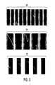
- the spatial frequency or frequencies of an imageare the rates of pixel change per unit distance, usually expressed in cycles per degree or radian.
- sine wave varying regions 300 and 301both have a single spatial frequency, although the spatial frequency for region 301 is lower than the spatial frequency for region 300 .
- Square wave varying region 302has a number of spatial frequencies, with the lowest spatial frequency for the region 302 equal to the sole spatial frequency for region 301 . Fourier analysis of image samples allows the spatial frequency or frequencies of an image to be identified.
- a primary object of the present inventionto provide, for use in a video receiver, a sampling system which adapts the sampling rate for sampling analog signals and/or the stored number of samples to the fixed or video image content, such that a higher rate, and equivalently a larger number of samples, are acquired for an image or video segment containing higher spatial frequencies while a lower number of samples (lower sampling rate) are retained for image or video segments containing lower spatial frequencies.
- the Nyquist theoremmay still be satisfied for each individual image segment, while information necessary for edge enhancement is retained.
- FIG. 1depicts a video system with sampling based upon spatial frequencies of the video image content according to one embodiment of the present invention
- FIGS. 2A through 2Care diagrams of sampling mechanisms for image sampling based upon spatial frequencies of the video image content according to various embodiment of the present invention.
- FIG. 3depicts gratings for image content having various spatial frequencies.
- FIGS. 1 and 2 A- 2 Cdiscussed below, and the various embodiments used to describe the principles of the present invention in this patent document are by way of illustration only and should not be construed in any way to limit the scope of the invention. Those skilled in the art will understand that the principles of the present invention may be implemented in any suitably arranged device.
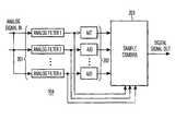
- FIG. 1depicts a video system with sampling based upon spatial frequencies of the video image content according to one embodiment of the present invention.
- the video system 100is implemented within a video receiver 101 having an input 102 receiving an analog video signal and optionally an output 103 for transmitting digital video data corresponding to the received analog video to a display, a storage device or system, or another device.
- Receiver 101may be a digital television (DTV) having a digital display, a satellite, terrestrial, or cable broadcast receiver for connection to a television, or the like.
- the present inventionmay also be employed for any receiver such as, for example, a broadband wireless Internet access receiver or any other video device receiving analog video information such as a video cassette recorder (VCR), a digital video recorder, or a digital versatile disk (DVD) player.
- VCRvideo cassette recorder
- DVDdigital versatile disk
- receiver 101employs content-dependent frequency of sampling or sample density within the resulting digital signal as described in further detail below.
- FIG. 1does not explicitly depict every component within a receiver system. Only those portions of such a system that are unique to the present invention and/or required for an understanding of the structure and operation of the present invention are shown.
- Receiver 101includes a sampling mechanism 104 which samples the analog video input signal at a frequency modulated by or dependent upon the spatial frequency of the sampled content.
- a higher sampling frequency(larger sampling density) is employed for image content having higher spatial frequencies and a lower sampling rate is employed for image content having lower spatial frequencies.
- the Nyquist theoremmay still be satisfied, with the sampling frequency set to twice the highest spatial frequency within the content being sampled.
- the resultis fewer samples for content having low spatial frequencies and more samples for image content having high spatial frequencies. If noise deteriorates the image or video, the larger number of samples for regions having higher spatial frequencies, mainly edges, help to preserve the original edge significantly better than fixed sampling rates. The additional samples are often necessary for many sharpness enhancement algorithms.
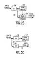
- FIGS. 2A through 2Care diagrams of sampling mechanisms for image sampling based upon spatial frequencies of the video image content according to various embodiment of the present invention.
- a number n(where n is any positive, nonzero integer) of analog filters 201 are employed by smapling mechanism 104 to separate the input signal's frequency spectrum.
- Each analog filter 201filters the input signal for a specific band of spatial frequencies.
- a number of corresponding analog-to-digital (A/D) converters 202each having different settings for the various filtered signals are employed to generate different digital representations having different sampling rates.
- An intelligent sample combination mechanism 203receiving both the output of filters 201 and the corresponding digital representations from converters 202 selects an output from one of converters 202 for each input signal segment and combines the selected representations to form the digital output signal.
- sampling mechanism 104includes a single analog-to-digital converter 204 employing a high, fixed sampling rate.
- the sampled input signalis then analyzed by signal analysis unit 205 to determine the highest spatial frequency within the sample image data.
- Signal analysis unit 205controls a downsampling unit 206 which receives the input samples to reduce the number of samples retained at image or video parts having low spatial frequencies and retain the high number of samples for image content having high spatial frequencies.
- the number of samples retained for a particular image segmentmay be related to the Nyquist theorem and the highest spatial frequency detected within the sampled image content.
- sampling mechanism 104includes a first analog-to-digital converter 207 employing a fixed sample rate equal to the highest sampling rate supported.
- a signal analysis unit 208analyzes the spatial frequencies within the sampled samples, then modulates the variable sampling rate employed by a second analog-to-digital converter 209 based upon the sampled content.
- a buffer(not shown) may be employed to correlate the sampling rate to the content being sampled.
- An initial sampling rate for converter 209is employed, with the sampling rate being increased during sampling when the sampled content's spatial frequencies are high (e.g., close to the chosen Nyquist frequency for the current sampling rate) and is otherwise lowered. Image segments which are determined to have been sampled at too low a rate may be resampled at a higher sampling rate.
- the number of samples or the size of the input segment for which the sampling rate is adjustedmay be either fixed or variable. Optimization of sample density for various segment lengths may be determined by considered all permutations.
- the present inventionemploys a sampling rate which is modulated based upon the spatial frequencies of the content being sampled. Higher sampling rates, and larger sample densities, are employed for content having high spatial frequencies while lower sampling rates are employed for content having low spatial frequencies. The Nyquist theorem may still be satisfied for particular segments of image data, and the necessary information for edge enhancement is retained.
- the resulting samplesare suitable for image standards employing run-length encoding (RLE), such as the motion picture experts group (MPEG) standard.
- RLErun-length encoding
- machine usable mediumsinclude: nonvolatile, hard-coded type mediums such as read only memories (ROMs) or erasable, electrically programmable read only memories (EEPROMs), recordable type mediums such as floppy disks, hard disk drives and compact disc read only memories (CD-ROMs) or digital versatile discs (DVDs), and transmission type mediums such as digital and analog communication links.
- ROMsread only memories
- EEPROMselectrically programmable read only memories
- CD-ROMscompact disc read only memories
- DVDsdigital versatile discs
Landscapes
- Engineering & Computer Science (AREA)
- Theoretical Computer Science (AREA)
- Multimedia (AREA)
- Signal Processing (AREA)
- Television Systems (AREA)
- Compression Or Coding Systems Of Tv Signals (AREA)
- Picture Signal Circuits (AREA)
- Analogue/Digital Conversion (AREA)
Abstract
Description
Claims (20)
Priority Applications (6)
| Application Number | Priority Date | Filing Date | Title |
|---|---|---|---|
| US09/966,038US8446530B2 (en) | 2001-09-28 | 2001-09-28 | Dynamic sampling |
| CNB028189930ACN1258908C (en) | 2001-09-28 | 2002-09-10 | Dynamic video sampling |
| JP2003533586AJP2005505202A (en) | 2001-09-28 | 2002-09-10 | Dynamic video sampling |
| PCT/IB2002/003731WO2003030523A1 (en) | 2001-09-28 | 2002-09-10 | Dynamic video sampling |
| KR10-2004-7004636AKR20040037199A (en) | 2001-09-28 | 2002-09-10 | Dynamic video sampling |
| EP02765223AEP1433309A1 (en) | 2001-09-28 | 2002-09-10 | Dynamic video sampling |
Applications Claiming Priority (1)
| Application Number | Priority Date | Filing Date | Title |
|---|---|---|---|
| US09/966,038US8446530B2 (en) | 2001-09-28 | 2001-09-28 | Dynamic sampling |
Publications (2)
| Publication Number | Publication Date |
|---|---|
| US20030063219A1 US20030063219A1 (en) | 2003-04-03 |
| US8446530B2true US8446530B2 (en) | 2013-05-21 |
Family
ID=25510844
Family Applications (1)
| Application Number | Title | Priority Date | Filing Date |
|---|---|---|---|
| US09/966,038Expired - Fee RelatedUS8446530B2 (en) | 2001-09-28 | 2001-09-28 | Dynamic sampling |
Country Status (6)
| Country | Link |
|---|---|
| US (1) | US8446530B2 (en) |
| EP (1) | EP1433309A1 (en) |
| JP (1) | JP2005505202A (en) |
| KR (1) | KR20040037199A (en) |
| CN (1) | CN1258908C (en) |
| WO (1) | WO2003030523A1 (en) |
Cited By (14)
| Publication number | Priority date | Publication date | Assignee | Title |
|---|---|---|---|---|
| US20140257528A1 (en)* | 2013-03-11 | 2014-09-11 | Johnson Controls Technology Company | Systems and methods for adaptive sampling rate adjustment |
| US9820171B2 (en) | 2010-09-14 | 2017-11-14 | Dali Wireless, Inc. | Remotely reconfigurable distributed antenna system and methods |
| US9867052B2 (en) | 2000-03-27 | 2018-01-09 | Commscope Technologies Llc | Multiprotocol antenna system for multiple service providers |
| US10080178B2 (en) | 2006-12-26 | 2018-09-18 | Dali Wireless, Inc. | Distributed antenna system |
| US10324424B2 (en) | 2013-03-11 | 2019-06-18 | Johnson Controls Technology Company | Control system with response time estimation and automatic operating parameter adjustment |
| US10333810B2 (en) | 2017-06-09 | 2019-06-25 | Johnson Controls Technology Company | Control system with asynchronous wireless data transmission |
| US10499269B2 (en) | 2015-11-12 | 2019-12-03 | Commscope Technologies Llc | Systems and methods for assigning controlled nodes to channel interfaces of a controller |
| US10498434B2 (en) | 2000-07-19 | 2019-12-03 | CommScope Technolgies LLC | Point-to-multipoint digital radio frequency transport |
| US10739028B2 (en) | 2017-06-09 | 2020-08-11 | Johnson Controls Technology Company | Thermostat with efficient wireless data transmission |
| US10868857B2 (en) | 2017-04-21 | 2020-12-15 | Johnson Controls Technology Company | Building management system with distributed data collection and gateway services |
| US11159129B2 (en) | 2002-05-01 | 2021-10-26 | Dali Wireless, Inc. | Power amplifier time-delay invariant predistortion methods and apparatus |
| US11297603B2 (en) | 2010-08-17 | 2022-04-05 | Dali Wireless, Inc. | Neutral host architecture for a distributed antenna system |
| US11418155B2 (en) | 2002-05-01 | 2022-08-16 | Dali Wireless, Inc. | Digital hybrid mode power amplifier system |
| USRE49377E1 (en) | 2002-12-03 | 2023-01-17 | Commscope Technologies Llc | Distributed digital antenna system |
Families Citing this family (12)
| Publication number | Priority date | Publication date | Assignee | Title |
|---|---|---|---|---|
| US7483059B2 (en)* | 2004-04-30 | 2009-01-27 | Hewlett-Packard Development Company, L.P. | Systems and methods for sampling an image sensor |
| US7471339B2 (en)* | 2004-06-02 | 2008-12-30 | Mstar Semiconductor, Inc. | High-speed video signal processing system |
| JP2006191216A (en)* | 2005-01-04 | 2006-07-20 | Nec Electronics Corp | Oversampling A / D converter circuit |
| US7986268B2 (en)* | 2006-05-08 | 2011-07-26 | Nxp B.V. | GPS RF front end and related method of providing a position fix, storage medium and apparatus for the same |
| US8754947B2 (en)* | 2008-05-07 | 2014-06-17 | Evertz Microsystems Ltd. | Systems and methods for comparing media signals |
| US8780209B2 (en)* | 2008-05-07 | 2014-07-15 | Evertz Microsystems Ltd. | Systems and methods for comparing media signals |
| US8677437B2 (en)* | 2008-05-07 | 2014-03-18 | Evertz Microsystems Ltd. | Systems and methods for calculating the delay between media signals |
| US9197327B2 (en)* | 2012-09-04 | 2015-11-24 | Cisco Technology, Inc. | Optical communication transmitter system |
| US9043062B2 (en)* | 2012-10-05 | 2015-05-26 | Ford Global Technologies, Llc | Hybrid electric vehicle powertrain and control system |
| US9612993B2 (en)* | 2014-06-28 | 2017-04-04 | Intel Corporation | Dynamically configurable analog frontend circuitry |
| US9825641B1 (en)* | 2014-09-12 | 2017-11-21 | The United States Of America As Represented By The Administrator Of The National Aeronautics And Space Administration | Reconfigurable sensor monitoring system |
| DE102018200786A1 (en)* | 2018-01-18 | 2019-07-18 | Robert Bosch Gmbh | Method and apparatus for sampling an analog sensor signal, and sensor system |
Citations (17)
| Publication number | Priority date | Publication date | Assignee | Title |
|---|---|---|---|---|
| US3324237A (en) | 1962-08-29 | 1967-06-06 | Nat Res Dev | Television and like data transmission systems |
| US4496937A (en)* | 1980-06-20 | 1985-01-29 | Tokyo Shibaura Denki Kabushiki Kaisha | Sampled signal generation circuit |
| US4626827A (en)* | 1982-03-16 | 1986-12-02 | Victor Company Of Japan, Limited | Method and system for data compression by variable frequency sampling |
| EP0259004A1 (en) | 1986-08-01 | 1988-03-09 | BRITISH TELECOMMUNICATIONS public limited company | Television transmission apparatus |
| US4755795A (en)* | 1986-10-31 | 1988-07-05 | Hewlett-Packard Company | Adaptive sample rate based on input signal bandwidth |
| US4763207A (en)* | 1985-10-15 | 1988-08-09 | R. R. Donnelley & Sons Company | Digital method and system for reproducing analog data |
| JPS63243882A (en) | 1987-03-31 | 1988-10-11 | Mitsubishi Electric Corp | Radar signal processing device |
| US4816829A (en) | 1987-04-30 | 1989-03-28 | R. R. Donnelley & Sons Company | Method of and apparatus for converting digital data between data formats |
| US5148270A (en) | 1990-02-26 | 1992-09-15 | Sony Corporation | Television signal receiving apparatus |
| US5150207A (en) | 1990-02-20 | 1992-09-22 | Sony Corporation | Video signal transmitting system |
| US5302950A (en)* | 1992-07-17 | 1994-04-12 | International Business Machines Corp. | Method of and apparatus for providing automatic determination of information sampling rate |
| US5576837A (en) | 1990-08-17 | 1996-11-19 | Samsung Electronics Co., Ltd. | Digital modulators for use with sub-nyquist sampling of raster-scanned samples of image intensity |
| US5612748A (en) | 1991-06-27 | 1997-03-18 | Nippon Hoso Kyokai | Sub-sample transmission system for improving picture quality in motional picture region of wide-band color picture signal |
| US5666386A (en) | 1993-11-26 | 1997-09-09 | Nec Corporation | Digital demodulating apparatus capable of selecting proper sampling clock for data transmission speed |
| US5841387A (en) | 1993-09-01 | 1998-11-24 | Texas Instruments Incorporated | Method and system for encoding a digital signal |
| EP1146323A1 (en) | 2000-04-14 | 2001-10-17 | Sagem Sa | Method and device for detecting the presence and energy of a given frequency in a sound and application to detection of knocking in combustion engines |
| US6473008B2 (en)* | 2000-02-07 | 2002-10-29 | Siemens Medical Systems, Inc. | System for sampling a data signal |
- 2001
- 2001-09-28USUS09/966,038patent/US8446530B2/ennot_activeExpired - Fee Related
- 2002
- 2002-09-10CNCNB028189930Apatent/CN1258908C/ennot_activeExpired - Fee Related
- 2002-09-10KRKR10-2004-7004636Apatent/KR20040037199A/ennot_activeCeased
- 2002-09-10JPJP2003533586Apatent/JP2005505202A/enactivePending
- 2002-09-10WOPCT/IB2002/003731patent/WO2003030523A1/enactiveApplication Filing
- 2002-09-10EPEP02765223Apatent/EP1433309A1/ennot_activeWithdrawn
Patent Citations (17)
| Publication number | Priority date | Publication date | Assignee | Title |
|---|---|---|---|---|
| US3324237A (en) | 1962-08-29 | 1967-06-06 | Nat Res Dev | Television and like data transmission systems |
| US4496937A (en)* | 1980-06-20 | 1985-01-29 | Tokyo Shibaura Denki Kabushiki Kaisha | Sampled signal generation circuit |
| US4626827A (en)* | 1982-03-16 | 1986-12-02 | Victor Company Of Japan, Limited | Method and system for data compression by variable frequency sampling |
| US4763207A (en)* | 1985-10-15 | 1988-08-09 | R. R. Donnelley & Sons Company | Digital method and system for reproducing analog data |
| EP0259004A1 (en) | 1986-08-01 | 1988-03-09 | BRITISH TELECOMMUNICATIONS public limited company | Television transmission apparatus |
| US4755795A (en)* | 1986-10-31 | 1988-07-05 | Hewlett-Packard Company | Adaptive sample rate based on input signal bandwidth |
| JPS63243882A (en) | 1987-03-31 | 1988-10-11 | Mitsubishi Electric Corp | Radar signal processing device |
| US4816829A (en) | 1987-04-30 | 1989-03-28 | R. R. Donnelley & Sons Company | Method of and apparatus for converting digital data between data formats |
| US5150207A (en) | 1990-02-20 | 1992-09-22 | Sony Corporation | Video signal transmitting system |
| US5148270A (en) | 1990-02-26 | 1992-09-15 | Sony Corporation | Television signal receiving apparatus |
| US5576837A (en) | 1990-08-17 | 1996-11-19 | Samsung Electronics Co., Ltd. | Digital modulators for use with sub-nyquist sampling of raster-scanned samples of image intensity |
| US5612748A (en) | 1991-06-27 | 1997-03-18 | Nippon Hoso Kyokai | Sub-sample transmission system for improving picture quality in motional picture region of wide-band color picture signal |
| US5302950A (en)* | 1992-07-17 | 1994-04-12 | International Business Machines Corp. | Method of and apparatus for providing automatic determination of information sampling rate |
| US5841387A (en) | 1993-09-01 | 1998-11-24 | Texas Instruments Incorporated | Method and system for encoding a digital signal |
| US5666386A (en) | 1993-11-26 | 1997-09-09 | Nec Corporation | Digital demodulating apparatus capable of selecting proper sampling clock for data transmission speed |
| US6473008B2 (en)* | 2000-02-07 | 2002-10-29 | Siemens Medical Systems, Inc. | System for sampling a data signal |
| EP1146323A1 (en) | 2000-04-14 | 2001-10-17 | Sagem Sa | Method and device for detecting the presence and energy of a given frequency in a sound and application to detection of knocking in combustion engines |
Cited By (31)
| Publication number | Priority date | Publication date | Assignee | Title |
|---|---|---|---|---|
| US10321328B2 (en) | 2000-03-27 | 2019-06-11 | Commscope Technologies Llc | Multiprotocol antenna system for multiple service providers |
| US9867052B2 (en) | 2000-03-27 | 2018-01-09 | Commscope Technologies Llc | Multiprotocol antenna system for multiple service providers |
| US10505635B2 (en) | 2000-07-19 | 2019-12-10 | Commscope Technologies Llc | Point-to-multipoint digital radio frequency transport |
| US10498434B2 (en) | 2000-07-19 | 2019-12-03 | CommScope Technolgies LLC | Point-to-multipoint digital radio frequency transport |
| US11159129B2 (en) | 2002-05-01 | 2021-10-26 | Dali Wireless, Inc. | Power amplifier time-delay invariant predistortion methods and apparatus |
| US11418155B2 (en) | 2002-05-01 | 2022-08-16 | Dali Wireless, Inc. | Digital hybrid mode power amplifier system |
| USRE49377E1 (en) | 2002-12-03 | 2023-01-17 | Commscope Technologies Llc | Distributed digital antenna system |
| USRE50112E1 (en) | 2002-12-03 | 2024-09-03 | Outdoor Wireless Networks LLC | Distributed digital antenna system |
| US10080178B2 (en) | 2006-12-26 | 2018-09-18 | Dali Wireless, Inc. | Distributed antenna system |
| US10334499B2 (en) | 2006-12-26 | 2019-06-25 | Dali Wireless, Inc. | Distributed antenna system |
| US11006343B2 (en) | 2006-12-26 | 2021-05-11 | Dali Wireless, Inc. | Distributed antenna system |
| US11818642B2 (en) | 2006-12-26 | 2023-11-14 | Dali Wireless, Inc. | Distributed antenna system |
| US11297603B2 (en) | 2010-08-17 | 2022-04-05 | Dali Wireless, Inc. | Neutral host architecture for a distributed antenna system |
| US10743317B1 (en) | 2010-09-14 | 2020-08-11 | Dali Wireless, Inc. | Remotely reconfigurable distributed antenna system and methods |
| US10701695B2 (en) | 2010-09-14 | 2020-06-30 | Dali Wireless, Inc. | Remotely reconfigurable distributed antenna system and methods |
| US9820171B2 (en) | 2010-09-14 | 2017-11-14 | Dali Wireless, Inc. | Remotely reconfigurable distributed antenna system and methods |
| US10159074B2 (en) | 2010-09-14 | 2018-12-18 | Dali Wireless, Inc. | Remotely reconfigurable distributed antenna system and methods |
| US12382444B2 (en) | 2010-09-14 | 2025-08-05 | Dali Wireless, Inc. | Remotely reconfigurable distributed antenna system and methods |
| US11013005B2 (en) | 2010-09-14 | 2021-05-18 | Dali Wireless, Inc. | Remotely reconfigurable distributed antenna system and methods |
| US11805504B2 (en) | 2010-09-14 | 2023-10-31 | Dali Wireless, Inc. | Remotely reconfigurable distributed antenna system and methods |
| US11368957B2 (en) | 2010-09-14 | 2022-06-21 | Dali Wireless, Inc. | Remotely reconfigurable distributed antenna system and methods |
| US20220295487A1 (en) | 2010-09-14 | 2022-09-15 | Dali Wireless, Inc. | Remotely reconfigurable distributed antenna system and methods |
| US9395708B2 (en)* | 2013-03-11 | 2016-07-19 | Johnson Controls Technology Company | Systems and methods for adaptive sampling rate adjustment |
| US20140257528A1 (en)* | 2013-03-11 | 2014-09-11 | Johnson Controls Technology Company | Systems and methods for adaptive sampling rate adjustment |
| US10324424B2 (en) | 2013-03-11 | 2019-06-18 | Johnson Controls Technology Company | Control system with response time estimation and automatic operating parameter adjustment |
| US10317856B2 (en) | 2013-03-11 | 2019-06-11 | Johnson Controls Technology Company | Control system with response time estimation |
| US10499269B2 (en) | 2015-11-12 | 2019-12-03 | Commscope Technologies Llc | Systems and methods for assigning controlled nodes to channel interfaces of a controller |
| US10868857B2 (en) | 2017-04-21 | 2020-12-15 | Johnson Controls Technology Company | Building management system with distributed data collection and gateway services |
| US11032172B2 (en) | 2017-06-09 | 2021-06-08 | Johnson Controls Technology Company | Asynchronous wireless data transmission system and method for asynchronously transmitting samples of a measured variable by a wireless sensor |
| US10739028B2 (en) | 2017-06-09 | 2020-08-11 | Johnson Controls Technology Company | Thermostat with efficient wireless data transmission |
| US10333810B2 (en) | 2017-06-09 | 2019-06-25 | Johnson Controls Technology Company | Control system with asynchronous wireless data transmission |
Also Published As
| Publication number | Publication date |
|---|---|
| JP2005505202A (en) | 2005-02-17 |
| US20030063219A1 (en) | 2003-04-03 |
| EP1433309A1 (en) | 2004-06-30 |
| KR20040037199A (en) | 2004-05-04 |
| CN1258908C (en) | 2006-06-07 |
| CN1559139A (en) | 2004-12-29 |
| WO2003030523A1 (en) | 2003-04-10 |
Similar Documents
| Publication | Publication Date | Title |
|---|---|---|
| US8446530B2 (en) | Dynamic sampling | |
| KR970003047B1 (en) | Variety signal recording and reproducing apparatus | |
| US8050289B1 (en) | Media transmission using aggregated bandwidth of disparate communication channels | |
| US7349502B2 (en) | Digital communication system and method for operating the system which can improve equalization performance according to channel state | |
| US20070279683A1 (en) | Communication Apparatus, Communication Method, Communication Transmission and Reception Apparatus, Communication Transmission and Reception Method, and Program | |
| US20020136538A1 (en) | Smart quality setting for personal TV recording | |
| US6904096B2 (en) | Video data processing device and video data processing method | |
| US20090097763A1 (en) | Converting video and image signal bit depths | |
| US20100020235A1 (en) | Co-channel interference remover | |
| KR20130070566A (en) | Adaptive video decoding circuitry and techniques | |
| CA2240010C (en) | Co-channel interference canceler in simulcast receiver and method thereof | |
| CN101969557B (en) | Image recording device, and image recording method | |
| CN1310424C (en) | Method for Optimizing Radio Frequency Signal Level Based on Information in Memory | |
| US8144252B2 (en) | Noise reduction apparatus and noise reduction method | |
| HU228608B1 (en) | Method for processing video signals, method for processing interlaced scan video signal or telecined film format signal and method for processing non-telecined progressive scan video signal | |
| JP4474748B2 (en) | Signal processing apparatus and method, video signal recording apparatus, and video signal reproducing apparatus | |
| JP4600091B2 (en) | Digital signal communication system, signal transmission device, and signal reception device for transmitting video and audio | |
| US20060067409A1 (en) | Image processing apparatus | |
| EP2166758B1 (en) | Image signal processing apparatus and image signal processing method | |
| JP2890740B2 (en) | Digital video signal playback device | |
| US20060182180A1 (en) | Encoding apparatus and method, decoding apparatus and method, recording medium, image processing system, and image processing method | |
| US20020054751A1 (en) | Digital signal recording apparatus and method thereof | |
| KR100820932B1 (en) | Apparatus and method for detecting ripple caused by multipath propagation and controlling receive antenna and tuner | |
| CN101018300A (en) | Method for time shift and television receiver | |
| WO1992017032A1 (en) | Television signal transmission system with two sets of channel symbols |
Legal Events
| Date | Code | Title | Description |
|---|---|---|---|
| AS | Assignment | Owner name:KONINKLIJKE PHILIPS ELECTRONICS N.V., NETHERLANDS Free format text:ASSIGNMENT OF ASSIGNORS INTEREST;ASSIGNOR:BELLERS, ERWIN B.;REEL/FRAME:012220/0122 Effective date:20010926 | |
| AS | Assignment | Owner name:NXP B.V., NETHERLANDS Free format text:ASSIGNMENT OF ASSIGNORS INTEREST;ASSIGNOR:KONINKLIJKE PHILIPS ELECTRONICS N.V.;REEL/FRAME:019719/0843 Effective date:20070704 Owner name:NXP B.V.,NETHERLANDS Free format text:ASSIGNMENT OF ASSIGNORS INTEREST;ASSIGNOR:KONINKLIJKE PHILIPS ELECTRONICS N.V.;REEL/FRAME:019719/0843 Effective date:20070704 | |
| AS | Assignment | Owner name:TRIDENT MICROSYSTEMS (FAR EAST) LTD.,CAYMAN ISLAND Free format text:ASSIGNMENT OF ASSIGNORS INTEREST;ASSIGNORS:TRIDENT MICROSYSTEMS (EUROPE) B.V.;NXP HOLDING 1 B.V.;REEL/FRAME:023928/0552 Effective date:20100208 Owner name:NXP HOLDING 1 B.V.,NETHERLANDS Free format text:ASSIGNMENT OF ASSIGNORS INTEREST;ASSIGNOR:NXP;REEL/FRAME:023928/0489 Effective date:20100207 Owner name:NXP HOLDING 1 B.V., NETHERLANDS Free format text:ASSIGNMENT OF ASSIGNORS INTEREST;ASSIGNOR:NXP;REEL/FRAME:023928/0489 Effective date:20100207 Owner name:TRIDENT MICROSYSTEMS (FAR EAST) LTD., CAYMAN ISLAN Free format text:ASSIGNMENT OF ASSIGNORS INTEREST;ASSIGNORS:TRIDENT MICROSYSTEMS (EUROPE) B.V.;NXP HOLDING 1 B.V.;REEL/FRAME:023928/0552 Effective date:20100208 | |
| AS | Assignment | Owner name:ENTROPIC COMMUNICATIONS, INC., CALIFORNIA Free format text:ASSIGNMENT OF ASSIGNORS INTEREST;ASSIGNORS:TRIDENT MICROSYSTEMS, INC.;TRIDENT MICROSYSTEMS (FAR EAST) LTD.;REEL/FRAME:028153/0440 Effective date:20120411 | |
| FEPP | Fee payment procedure | Free format text:PAYER NUMBER DE-ASSIGNED (ORIGINAL EVENT CODE: RMPN); ENTITY STATUS OF PATENT OWNER: LARGE ENTITY Free format text:PAYOR NUMBER ASSIGNED (ORIGINAL EVENT CODE: ASPN); ENTITY STATUS OF PATENT OWNER: LARGE ENTITY | |
| STCF | Information on status: patent grant | Free format text:PATENTED CASE | |
| AS | Assignment | Owner name:ENTROPIC COMMUNICATIONS, INC., CALIFORNIA Free format text:MERGER AND CHANGE OF NAME;ASSIGNORS:EXCALIBUR ACQUISITION CORPORATION;ENTROPIC COMMUNICATIONS, INC.;ENTROPIC COMMUNICATIONS, INC.;REEL/FRAME:035706/0267 Effective date:20150430 | |
| AS | Assignment | Owner name:ENTROPIC COMMUNICATIONS, LLC, CALIFORNIA Free format text:MERGER AND CHANGE OF NAME;ASSIGNORS:ENTROPIC COMMUNICATIONS, INC.;EXCALIBUR SUBSIDIARY, LLC;ENTROPIC COMMUNICATIONS, LLC;REEL/FRAME:035717/0628 Effective date:20150430 | |
| FPAY | Fee payment | Year of fee payment:4 | |
| AS | Assignment | Owner name:JPMORGAN CHASE BANK, N.A., AS COLLATERAL AGENT, IL Free format text:SECURITY AGREEMENT;ASSIGNORS:MAXLINEAR, INC.;ENTROPIC COMMUNICATIONS, LLC (F/K/A ENTROPIC COMMUNICATIONS, INC.);EXAR CORPORATION;REEL/FRAME:042453/0001 Effective date:20170512 Owner name:JPMORGAN CHASE BANK, N.A., AS COLLATERAL AGENT, ILLINOIS Free format text:SECURITY AGREEMENT;ASSIGNORS:MAXLINEAR, INC.;ENTROPIC COMMUNICATIONS, LLC (F/K/A ENTROPIC COMMUNICATIONS, INC.);EXAR CORPORATION;REEL/FRAME:042453/0001 Effective date:20170512 | |
| AS | Assignment | Owner name:MUFG UNION BANK, N.A., CALIFORNIA Free format text:SUCCESSION OF AGENCY (REEL 042453 / FRAME 0001);ASSIGNOR:JPMORGAN CHASE BANK, N.A.;REEL/FRAME:053115/0842 Effective date:20200701 | |
| MAFP | Maintenance fee payment | Free format text:PAYMENT OF MAINTENANCE FEE, 8TH YEAR, LARGE ENTITY (ORIGINAL EVENT CODE: M1552); ENTITY STATUS OF PATENT OWNER: LARGE ENTITY Year of fee payment:8 | |
| AS | Assignment | Owner name:MAXLINEAR, INC., CALIFORNIA Free format text:RELEASE BY SECURED PARTY;ASSIGNOR:MUFG UNION BANK, N.A.;REEL/FRAME:056656/0204 Effective date:20210623 Owner name:EXAR CORPORATION, CALIFORNIA Free format text:RELEASE BY SECURED PARTY;ASSIGNOR:MUFG UNION BANK, N.A.;REEL/FRAME:056656/0204 Effective date:20210623 Owner name:MAXLINEAR COMMUNICATIONS LLC, CALIFORNIA Free format text:RELEASE BY SECURED PARTY;ASSIGNOR:MUFG UNION BANK, N.A.;REEL/FRAME:056656/0204 Effective date:20210623 | |
| AS | Assignment | Owner name:WELLS FARGO BANK, NATIONAL ASSOCIATION, COLORADO Free format text:SECURITY AGREEMENT;ASSIGNORS:MAXLINEAR, INC.;MAXLINEAR COMMUNICATIONS, LLC;EXAR CORPORATION;REEL/FRAME:056816/0089 Effective date:20210708 | |
| FEPP | Fee payment procedure | Free format text:MAINTENANCE FEE REMINDER MAILED (ORIGINAL EVENT CODE: REM.); ENTITY STATUS OF PATENT OWNER: LARGE ENTITY | |
| LAPS | Lapse for failure to pay maintenance fees | Free format text:PATENT EXPIRED FOR FAILURE TO PAY MAINTENANCE FEES (ORIGINAL EVENT CODE: EXP.); ENTITY STATUS OF PATENT OWNER: LARGE ENTITY | |
| STCH | Information on status: patent discontinuation | Free format text:PATENT EXPIRED DUE TO NONPAYMENT OF MAINTENANCE FEES UNDER 37 CFR 1.362 | |
| FP | Lapsed due to failure to pay maintenance fee | Effective date:20250521 |