US8446374B2 - Detecting a palm touch on a surface - Google Patents
Detecting a palm touch on a surfaceDownload PDFInfo
- Publication number
- US8446374B2 US8446374B2US12/269,823US26982308AUS8446374B2US 8446374 B2US8446374 B2US 8446374B2US 26982308 AUS26982308 AUS 26982308AUS 8446374 B2US8446374 B2US 8446374B2
- Authority
- US
- United States
- Prior art keywords
- touch
- touches
- distance
- determining
- input
- Prior art date
- Legal status (The legal status is an assumption and is not a legal conclusion. Google has not performed a legal analysis and makes no representation as to the accuracy of the status listed.)
- Expired - Fee Related, expires
Links
Images


Classifications
- G—PHYSICS
- G06—COMPUTING OR CALCULATING; COUNTING
- G06F—ELECTRIC DIGITAL DATA PROCESSING
- G06F3/00—Input arrangements for transferring data to be processed into a form capable of being handled by the computer; Output arrangements for transferring data from processing unit to output unit, e.g. interface arrangements
- G06F3/01—Input arrangements or combined input and output arrangements for interaction between user and computer
- G06F3/03—Arrangements for converting the position or the displacement of a member into a coded form
- G06F3/033—Pointing devices displaced or positioned by the user, e.g. mice, trackballs, pens or joysticks; Accessories therefor
- G06F3/0354—Pointing devices displaced or positioned by the user, e.g. mice, trackballs, pens or joysticks; Accessories therefor with detection of 2D relative movements between the device, or an operating part thereof, and a plane or surface, e.g. 2D mice, trackballs, pens or pucks
- G06F3/03543—Mice or pucks
- G—PHYSICS
- G06—COMPUTING OR CALCULATING; COUNTING
- G06F—ELECTRIC DIGITAL DATA PROCESSING
- G06F3/00—Input arrangements for transferring data to be processed into a form capable of being handled by the computer; Output arrangements for transferring data from processing unit to output unit, e.g. interface arrangements
- G06F3/01—Input arrangements or combined input and output arrangements for interaction between user and computer
- G06F3/03—Arrangements for converting the position or the displacement of a member into a coded form
- G06F3/033—Pointing devices displaced or positioned by the user, e.g. mice, trackballs, pens or joysticks; Accessories therefor
- G06F3/0354—Pointing devices displaced or positioned by the user, e.g. mice, trackballs, pens or joysticks; Accessories therefor with detection of 2D relative movements between the device, or an operating part thereof, and a plane or surface, e.g. 2D mice, trackballs, pens or pucks
- G06F3/03547—Touch pads, in which fingers can move on a surface
- G—PHYSICS
- G06—COMPUTING OR CALCULATING; COUNTING
- G06F—ELECTRIC DIGITAL DATA PROCESSING
- G06F3/00—Input arrangements for transferring data to be processed into a form capable of being handled by the computer; Output arrangements for transferring data from processing unit to output unit, e.g. interface arrangements
- G06F3/01—Input arrangements or combined input and output arrangements for interaction between user and computer
- G06F3/048—Interaction techniques based on graphical user interfaces [GUI]
- G06F3/0487—Interaction techniques based on graphical user interfaces [GUI] using specific features provided by the input device, e.g. functions controlled by the rotation of a mouse with dual sensing arrangements, or of the nature of the input device, e.g. tap gestures based on pressure sensed by a digitiser
- G06F3/0488—Interaction techniques based on graphical user interfaces [GUI] using specific features provided by the input device, e.g. functions controlled by the rotation of a mouse with dual sensing arrangements, or of the nature of the input device, e.g. tap gestures based on pressure sensed by a digitiser using a touch-screen or digitiser, e.g. input of commands through traced gestures
- G06F3/04883—Interaction techniques based on graphical user interfaces [GUI] using specific features provided by the input device, e.g. functions controlled by the rotation of a mouse with dual sensing arrangements, or of the nature of the input device, e.g. tap gestures based on pressure sensed by a digitiser using a touch-screen or digitiser, e.g. input of commands through traced gestures for inputting data by handwriting, e.g. gesture or text
Definitions
- Thisrelates to a touch sensitive mouse used as an input device for a computing system and, more particularly, to methods for detecting a palm touch on the mouse surface.
- Most computing systemscan receive input from a user via an input device such as a mouse.
- the mousecan allow the user to move an input pointer, e.g., a cursor, in a user interface (UI) on a display screen of the computing system and to make a selection in the UI with the pointer, thereby triggering various operations in the computing system.
- the mousecan include a mechanism, such as an optical sensor, a trackball, a gyroscope, an accelerometer, and so on, for tracking its motion, which can be translated into signals that the computing system can use to move the input pointer in the UI.
- the motion of the mousecan generally correspond to the motion of the input pointer in the UI. Thus, by moving the mouse on a surface, the user can move the input pointer in similar directions in the UI.
- the mousecan also include a mechanism, such as a click button, a scroll wheel, a touch panel, and so on, for data selection in the UI, which can be translated into signals that the computing system can use to select display elements in the UI corresponding to various operations in the computing system.
- Click buttons and scroll wheelsas physically manipulable mechanisms, can simply rely on the user to press or rotate them to perform data selection.
- Touch panelson the other hand, can rely on the user to make a recognizable gesture on a touch surface of the touch panel to perform data selection.
- a touch at a farther distant location on the touch surface relative to other touches on the touch surfacecan be indicative of a palm touch.
- an expected distance between finger touchescan be determined. Any touch at a location beyond that expected distance can be considered a palm touch.
- a touch having a larger touch radius relative to other touch radiican be indicative of a palm touch.
- a predetermined palm touch radiuscan be set. Any touch have a radius that exceed the predetermined palm touch radius can be considered a palm touch.
- FIG. 1illustrates an exemplary touch sensor panel indicating edge regions of the panel according to embodiments of the invention.
- FIG. 2illustrates top and side views of an exemplary touch sensitive mouse having a touch sensor panel as in FIG. 1 according to embodiments of the invention.
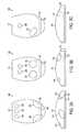
- FIGS. 3 a through 3 cillustrate exemplary touches on top and side surfaces of a touch sensitive mouse as in FIG. 2 according to embodiments of the invention.
- FIG. 4illustrates exemplary touches as captured in a touch image that can be made on a touch sensitive mouse according to embodiments of the invention.
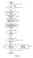
- FIG. 5illustrates an exemplary method for detecting a palm touch on a touch sensitive mouse according to embodiments of the invention.
- FIG. 6illustrates an exemplary computing system implementing the algorithm for detecting a palm touch on a touch sensitive mouse according to embodiments of the invention.
- Thisrelates to detecting a palm touch on a mouse surface using a method that can take into account the location and size of the touch.
- a touch at a lower location on the mouse relative to other touches or having a larger touch radius relative to other touchescan be indicative of a palm touch.
- FIG. 1illustrates an exemplary touch sensor panel indicating edge regions of the panel according to embodiments of the invention.
- Edge band 102can be created around the boundaries of touch sensor panel 100 , surrounding center area 104 .
- the edge band 102can be 1 mm wide at the side and bottom edges of the panel 100 and have an 8 mm radius at the bottom corners of the panel.
- the edge band 102can be used to help eliminate spurious or useless touches, as will be described below.
- FIG. 2illustrates top and side views of an exemplary touch sensitive mouse having a touch sensor panel as in FIG. 1 according to embodiments of the invention.
- Touch sensor panel 100can be formed on the top and sides of touch sensitive mouse 200 , except in those regions of the mouse where a user's touch is not expected to be utilized for mouse operations, e.g., at the very bottom edges of the mouse top and side surfaces.
- Edge band 102can be created near the bottom edges of the top and side surfaces of the mouse 200 .
- Center area 104can be created on the top and upper side surfaces of the mouse 200 .
- the touch sensor panel 100can be formed over the mouse top and side surfaces, ending about 2 mm from the very bottom edge of the top surface and about 1 mm from the very bottom edge of the side surfaces.
- Edge band 102can be about 1 mm wide at the bottom edge of the panel 100 near the bottom edge of the top surface of the mouse 200 , about 1 mm wide at the side edges of the panel in the bottom one-third of the side surfaces of the mouse, and about 8 mm in radius at the bottom corners of the panel near the bottom edges of the top and side surfaces of the mouse.
- FIGS. 3 a through 3 cillustrate exemplary touches on top and side surfaces of a touch sensitive mouse as in FIG. 2 according to embodiments of the invention.
- touch sensitive mouse 200can be touched with a right hand to produce a touch image indicating finger tip touches 300 , thumb touch 310 , and palm touches 330 .
- Thiscan represent a typical hand pose for either moving the mouse or simply resting the hand on the mouse.
- Finger tip touches 300can be in the upper center area 104 of touch sensor panel 100 on the top surface of the mouse 200 .
- Thumb touch 310can straddle the side center area 104 and the side edge band 102 of the touch sensor panel 100 on the side surface of the mouse 200 .
- Palm touches 330can straddle the lower center area 104 and the bottom edge band 102 of the touch sensor panel 100 on the top and side surfaces of the mouse 200 .
- touch sensitive mouse 200can be touched by the right hand to produce a touch image indicating finger tip touches 300 and palm touches 330 .
- Thiscan represent a typical hand pose at the beginning or ending of a “scroll” gesture (moving the fingers up or down) or a “finger zoom” gesture (moving the fingers together).
- Finger tip touches 300can be in the upper center area 104 of touch sensor panel 100 on the top surface of the mouse 200 .
- Palm touches 330can be in the lower center area 104 of the touch sensor panel 100 on the top surface of the mouse 200 .
- touch sensitive mouse 200can be touched by the right hand to produce a touch image indicating finger tip touch 300 and thumb touch 310 .
- Thiscan represent a typical hand pose at the beginning of a “thumb zoom” gesture (moving the thumb and finger together).
- Finger tip touch 300can be in the upper center area 104 of touch sensor panel 100 on the top surface of the mouse 200 .
- Thumb touch 310can be in the lower center area 104 of the touch sensor panel 100 on the top surface of the mouse 200 .
- FIG. 4illustrates exemplary touches as captured in a touch image that can be made on a touch sensitive mouse according to embodiments of the invention.
- Touch 300 as captured in a touch imagecan be defined as having centroid 302 at the center of mass of the touch with major and minor radii 304 and 306 defining the approximate boundaries of touch area 308 .
- the touch 300can have an elliptical, almost circular, shape, where the major and minor radii 304 and 306 can be approximately the same, indicative of a detected touch of a finger tip.
- Touch 310 as captured in a touch imagecan be defined as having centroid 312 at the center of mass of the touch with major and minor radii 314 and 316 defining the approximate boundaries of touch area 318 .
- the touch 310can have an elliptical shape, where the major and minor radii 314 and 316 can be oriented substantially diagonally and the major radius can be longer than the minor radius, indicative of a detected touch of a thumb.
- the centroid 312 of the touch 310can be farther along the major radius 314 than the centroid 302 of the touch 300 , indicating a more elongated touch area.
- the touch area 318 of the touch 310can also be larger than the touch area 308 of the touch 300 .
- Touch 320 as captured in a touch imagecan be defined as having centroid 322 at the center of mass of the touch with major and minor radii 324 and 326 defining the approximate boundaries of touch area 328 .
- the touch 320can have an elliptical shape, where the major radius 324 can be longer than the minor radius 326 , indicative of a detected touch of a flat finger.
- the centroid 322 of the touch 320can be lower in the y-direction than the centroid 302 of the touch 300 , indicating a more elongated touch area.
- the touch area 328 of the touch 320can also be larger than the touch area 308 of the touch 300 .
- Touch 330 as captured in a touch imagecan be defined as having centroid 332 at the center of mass of the touch with major and minor radii 334 and 336 defining the approximate boundaries of touch area 338 .
- the touch 330can have an elliptical, almost circular shape, where the major and minor radii 334 and 336 can be approximately the same and longer than the major and minor radii 304 and 306 , indicative of a detected touch of a palm.
- the centroid 332 of the touch 330can be lower in the y-direction than the centroids of the other touches.
- the major and minor radii 334 and 336can be longer than the radii of the other touches.
- the touch area 338 of the touch 330can also be larger than the touch areas of the other touches.
- hand and finger posesare not limited to those illustrated herein, but may include any poses that can be made on a touch sensitive mouse according to embodiments of the invention. It is further to be understood that the touch surface is not limited to a mouse surface, but may include any input device's touch surface capable of receiving hand and finger poses according to embodiments of the invention.
- FIG. 5illustrates an exemplary method for detecting a palm touch on a touch sensitive mouse according to embodiments of the invention.
- a determinationcan be made whether there have been one or more touches on a surface of the touch sensitive mouse ( 505 ). Generally, multiple touches can be made substantially simultaneously on the touch surface. If there have been one or more touches, a touch image can be captured to indicate the touches (such as those shown in FIG. 4 ) made on the touch surface.
- Those touches that either straddle the center area and the edge band of the mouse touch surface or rest within the edge bandcan be marked ( 510 ). Marking of touches is disclosed in U.S. patent application Ser. No. 12/242,772 entitled “Selective Rejection of Touch Contacts in an Edge Region of a Touch Surface,” the contents of which are incorporated herein by reference in their entirety for all purposes.
- the markingscan indicate those touches that can generally be ignored as either spurious or useless in determining gestures. For example, thumb touch 310 and palm touches 330 in FIG. 3 a can be ignored since they straddle the center area and the edge band of the mouse touch surface.
- the remaining touchesi.e., the non-edge touches, that are in the center area of the mouse touch surface can be ranked based on their y-coordinates in the touch image ( 515 ). For example, the topmost touch in the image can be ranked as “1,” the second topmost touch can be ranked as “2,” and so on, down to the bottommost touch in the image.
- the minor radii for the ranked touchescan be extracted from the touch image ( 520 ). This can be done using standard signal processing techniques. As shown in FIG. 4 , the minor radius of a palm touch can be discernibly larger than the minor radii of finger tip, thumb, and flat finger touches. This size difference can be used to detect a palm touch, as will be described below.
- the topmost touchcan be assumed to be made by a finger because a palm generally cannot touch near bottom center of the mouse touch surface unless fingers are also touching the surface.
- the expected distance between finger touches on the mousecan be calculated ( 525 ). Any touches beyond the expected distances are likely palm touches. As such, the expected distance can be considered as a palm threshold distance.
- two touchescould be made on the mouse touch surface by two fingers, a (top) finger and a thumb, or a (top) finger and a palm.
- the lower (i.e., the second) touch's expected palm threshold distance d 2 from the topmost touchcan be set fairly large to accommodate separation in the case of a finger and a thumb of about 60 to 70 mm. A separation beyond that can indicate a finger and a palm.
- Three touches made on the mouse touch surface by two fingers and a thumbmay not be supported because the two fingers and thumb may not comfortably fit on the mouse in a way that can provide a usable gesture.
- the remaining three touches that could be made on the mouse touch surfaceinclude three fingers, two fingers and a palm, or one finger and two palms (i.e., two touches by the same palm). Since the expected vertical separation for three fingers is smaller than the expected vertical separation for a finger and a thumb, the lower (i.e., the third) touch's expected palm threshold distance d 3 from the topmost touch can be somewhat smaller than d 2 . Four touches from four fingers may only fit on the mouse touch surface if the fingers are scrunched together. As such, the lower (i.e., the fourth) touch's expected palm threshold distance d 4 from the topmost touch can be as small as or smaller than d 3 .
- the lower (i.e., fifth or more) touch's expected palm threshold distance d 5 from the topmost touchcan be at least as small as d 4 . Accordingly, d 2 >d 3 >d 4 ⁇ d 5 . In some embodiments, d 2 can be 66 mm, d 3 44 mm, and d 4 and d 5 22 mm.
- the y-coordinate of the topmost touch in the touch imagecan be used as a reference when identifying lower touches in the image.
- a determinationcan be made whether the distance between the topmost touch and a ranked lower touch is greater than the expected distance d r as calculated above ( 530 ). The determination can be made as follows.
- y ris the y-coordinate of the lower rth ranked touch
- y 1is the y-coordinate of the topmost touch
- d ris the expected distance between fingers for that rank as calculated in step 525 . Accordingly, if the y-coordinate of the lower touch is farther away from the y-coordinate of the topmost touch than the expected distance, then the lower touch can be identified as a palm touch ( 540 ).
- the touchcan be identified as a finger touch ( 545 ).
- palm touches 330 in FIG. 3 bcan be identified and later ignored as not being part of a scroll or finger zoom gesture made by finger touches 300 .
- Thumb touch 310 in FIG. 3 ccan be identified as not being a palm touch and as being part of a thumb zoom gesture made with finger touch 300 .
- FIG. 6illustrates an exemplary computing system implementing the algorithm for detecting a palm touch on a touch sensitive mouse according to embodiments of the invention.
- computing system 600can include one or more panel processors 602 , which can execute software or firmware implementing the algorithm for palm detection according to embodiments of the invention, and peripherals 604 , and panel subsystem 606 .
- Peripherals 604can include, but are not limited to, random access memory (RAM) or other types of memory or storage, watchdog timers and the like.
- Panel subsystem 606can include, but is not limited to, one or more sense channels 608 , channel scan logic (analog or digital) 610 and driver logic (analog or digital) 614 .
- Channel scan logic 610can access RAM 612 , autonomously read data from sense channels 608 and provide control for the sense channels.
- channel scan logic 610can control driver logic 614 to generate stimulation signals 616 at various phases that can be simultaneously applied to drive lines of touch sensor panel 624 .
- Panel subsystem 606can operate at a low digital logic voltage level (e.g. 1.7 to 3.3V).
- Driver logic 614can generate a supply voltage greater that the digital logic level supply voltages by cascading two charge storage devices, e.g., capacitors, together to form charge pump 615 .
- Charge pump 615can be used to generate stimulation signals 616 that can have amplitudes of about twice the digital logic level supply voltages (e.g. 3.4 to 6.6V).
- FIG. 6shows charge pump 615 separate from driver logic 614 , the charge pump can be part of the driver logic.
- panel subsystem 606 , panel processor 602 and peripherals 604can be integrated into a single application specific integrated circuit (ASIC).
- Touch sensor panel 624can include a capacitive sensing medium having a plurality of drive lines and a plurality of sense lines, although other sensing media can also be used.
- the drive and sense linescan be formed from a transparent conductive medium such as Indium Tin Oxide (ITO) or Antimony Tin Oxide (ATO), although other transparent and non-transparent materials such as copper can also be used.
- the drive and sense linescan be formed on a single side of a substantially transparent substrate, on opposite sides of the substrate, or on two separate substrates separated by the dielectric material. Each intersection of drive and sense lines can represent a capacitive sensing node and can be viewed as picture element (pixel) 626 , which can be particularly useful when touch sensor panel 624 is viewed as capturing an “image” of touch.
- pixelpicture element
- the pattern of touch sensors in the multi-touch panel at which a touch event occurredcan be viewed as an “image” of touch (e.g. a pattern of fingers touching the panel).)
- the capacitance between the drive and sense lines and local system groundappears as a stray capacitance Cstray and the capacitance at the intersections of the drive and sense lines, i.e., the pixels, as a mutual signal capacitance Csig when the given drive line is stimulated with an alternating current (AC) signal.
- ACalternating current
- Each sense line of touch sensor panel 624can drive sense channel 608 in panel subsystem 606 .
- Touch sensor panel 624can cover a portion or substantially all of a surface of an input device, such as a mouse.
- Computing system 600can also include host processor 628 for receiving outputs from panel processor 602 and performing actions based on the outputs that can include, but are not limited to, moving one or more objects such as a cursor or pointer, scrolling or panning, adjusting control settings, opening a file or document, viewing a menu, making a selection, executing instructions, operating a peripheral device coupled to the host device, answering a telephone call, placing a telephone call, terminating a telephone call, changing the volume or audio settings, storing information related to telephone communications such as addresses, frequently dialed numbers, received calls, missed calls, logging onto a computer or a computer network, permitting authorized individuals access to restricted areas of the computer or computer network, loading a user profile associated with a user's preferred arrangement of the computer desktop, permitting access to web content, launching a particular program, encrypting or decoding a message, and/or the like.
- host processor 628for receiving outputs from panel processor 602 and performing actions based on the outputs that can include, but are not limited to,
- Host processor 628can execute software or firmware implementing the algorithm for palm detection according to embodiments of the invention. Host processor 628 can also perform additional functions that may not be related to panel processing, and can be coupled to program storage 632 and display device 630 such as an LCD display for providing a UI to a user of the device. Display device 630 together with touch sensor panel 624 , when located partially or entirely under the touch sensor panel, can form a touch screen.
- firmwarestored in memory (e.g. one of the peripherals 604 in FIG. 6 ) and executed by panel processor 602 , or stored in program storage 632 and executed by host processor 628 .
- the firmwarecan also be stored and/or transported within any computer-readable medium for use by or in connection with an instruction execution system, apparatus, or device, such as a computer-based system, processor-containing system, or other system that can fetch the instructions from the instruction execution system, apparatus, or device and execute the instructions.
- a “computer-readable medium”can be any medium that can contain or store the program for use by or in connection with the instruction execution system, apparatus, or device.
- the computer readable mediumcan include, but is not limited to, an electronic, magnetic, optical, electromagnetic, infrared, or semiconductor system, apparatus or device, a portable computer diskette (magnetic), a random access memory (RAM) (magnetic), a read-only memory (ROM) (magnetic), an erasable programmable read-only memory (EPROM) (magnetic), a portable optical disc such a CD, CD-R, CD-RW, DVD, DVD-R, or DVD-RW, or flash memory such as compact flash cards, secured digital cards, USB memory devices, memory sticks, and the like.
- the firmwarecan also be propagated within any transport medium for use by or in connection with an instruction execution system, apparatus, or device, such as a computer-based system, processor-containing system, or other system that can fetch the instructions from the instruction execution system, apparatus, or device and execute the instructions.
- a “transport medium”can be any medium that can communicate, propagate or transport the program for use by or in connection with the instruction execution system, apparatus, or device.
- the transport readable mediumcan include, but is not limited to, an electronic, magnetic, optical, electromagnetic or infrared wired or wireless propagation medium.
- the sensor panelis not limited to a touch sensor panel, as described in FIG. 6 , but may be a proximity sensor panel or any other sensor panel capable of sensing a touch or hover event and detecting a palm touch according to embodiments of the invention.
- the touch sensors in the touch sensor panelmay be described herein in terms of an orthogonal array of touch sensors having rows and columns, it should be understood that embodiments of this invention are not limited to orthogonal arrays, but can be generally applicable to touch sensors arranged in any number of dimensions and orientations, including diagonal, concentric circle, and three-dimensional and random orientations.
- the touch sensor panel described hereincan be either a single-touch or a multi-touch sensor panel.
- An exemplary touch sensitive mouse 200 as in FIG. 2can be utilized to execute palm detection algorithms according to embodiments of the invention.
- the mouse 200can communicate with the computing system 600 via cable.
- the mouse 200can communicate with the computing system 600 via a wireless connection.
Landscapes
- Engineering & Computer Science (AREA)
- General Engineering & Computer Science (AREA)
- Theoretical Computer Science (AREA)
- Human Computer Interaction (AREA)
- Physics & Mathematics (AREA)
- General Physics & Mathematics (AREA)
- Position Input By Displaying (AREA)
Abstract
Description
|y1−yr|>drindicates palm. (1)
Here, yris the y-coordinate of the lower rth ranked touch, y1is the y-coordinate of the topmost touch, and dris the expected distance between fingers for that rank as calculated in
Claims (20)
Priority Applications (1)
| Application Number | Priority Date | Filing Date | Title |
|---|---|---|---|
| US12/269,823US8446374B2 (en) | 2008-11-12 | 2008-11-12 | Detecting a palm touch on a surface |
Applications Claiming Priority (1)
| Application Number | Priority Date | Filing Date | Title |
|---|---|---|---|
| US12/269,823US8446374B2 (en) | 2008-11-12 | 2008-11-12 | Detecting a palm touch on a surface |
Publications (2)
| Publication Number | Publication Date |
|---|---|
| US20100117961A1 US20100117961A1 (en) | 2010-05-13 |
| US8446374B2true US8446374B2 (en) | 2013-05-21 |
Family
ID=42164758
Family Applications (1)
| Application Number | Title | Priority Date | Filing Date |
|---|---|---|---|
| US12/269,823Expired - Fee RelatedUS8446374B2 (en) | 2008-11-12 | 2008-11-12 | Detecting a palm touch on a surface |
Country Status (1)
| Country | Link |
|---|---|
| US (1) | US8446374B2 (en) |
Cited By (5)
| Publication number | Priority date | Publication date | Assignee | Title |
|---|---|---|---|---|
| US20140267149A1 (en)* | 2013-03-18 | 2014-09-18 | Alps Electric Co., Ltd. | Input device |
| US9569045B2 (en) | 2014-05-21 | 2017-02-14 | Apple Inc. | Stylus tilt and orientation estimation from touch sensor panel images |
| US9952709B2 (en) | 2015-12-11 | 2018-04-24 | Synaptics Incorporated | Using hybrid signal for large input object rejection |
| US10296146B2 (en) | 2015-12-22 | 2019-05-21 | Microsoft Technology Licensing, Llc | System and method for detecting grip of a touch enabled device |
| US10423268B2 (en) | 2015-12-22 | 2019-09-24 | Microsoft Technology Licensing, Llc | System and method for detecting grounding state of a touch enabled computing device |
Families Citing this family (17)
| Publication number | Priority date | Publication date | Assignee | Title |
|---|---|---|---|---|
| TWI403940B (en)* | 2008-12-03 | 2013-08-01 | Au Optronics Corp | Detecting method for photo sensor touch panel and touch control electronic apparatus using the same |
| JP5446426B2 (en)* | 2009-04-24 | 2014-03-19 | パナソニック株式会社 | Position detection device |
| KR101660842B1 (en)* | 2009-11-05 | 2016-09-29 | 삼성전자주식회사 | Touch input method and apparatus |
| CN101840296A (en)* | 2010-03-17 | 2010-09-22 | 敦泰科技(深圳)有限公司 | Detection circuit of capacitance-type touch screen and booster circuit thereof |
| US9524041B2 (en)* | 2010-12-22 | 2016-12-20 | Intel Corporation | Touch sensor gesture recognition for operation of mobile devices |
| US8593421B2 (en) | 2011-03-22 | 2013-11-26 | Adobe Systems Incorporated | Local coordinate frame user interface for multitouch-enabled devices |
| US8553001B2 (en)* | 2011-03-22 | 2013-10-08 | Adobe Systems Incorporated | Methods and apparatus for determining local coordinate frames for a human hand |
| WO2013039544A1 (en) | 2011-08-10 | 2013-03-21 | Cypress Semiconductor Corporation | Methods and apparatus to detect a presence of a conductive object |
| US20130207913A1 (en) | 2012-02-09 | 2013-08-15 | Sony Mobile Communications Inc. | Touch panel device, portable terminal, position detecting method, and recording medium |
| US9632612B2 (en) | 2012-02-23 | 2017-04-25 | Parade Technologies, Ltd. | Circuits, systems, and methods for processing the proximity of large objects, including large objects on touch screens |
| KR101987098B1 (en)* | 2012-09-25 | 2019-09-30 | 삼성전자주식회사 | Method for processing touch input, machine-readable storage medium and portable terminal |
| WO2014172454A1 (en)* | 2013-04-16 | 2014-10-23 | Cirque Corporation | Graduated palm rejection to improve touch sensor performance |
| US9665162B2 (en)* | 2014-03-25 | 2017-05-30 | Htc Corporation | Touch input determining method which can determine if the touch input is valid or not valid and electronic apparatus applying the method |
| CN104951226B (en)* | 2014-03-25 | 2018-08-24 | 宏达国际电子股份有限公司 | Touch input judging method and electronic device using the touch input judging method |
| US10963159B2 (en)* | 2016-01-26 | 2021-03-30 | Lenovo (Singapore) Pte. Ltd. | Virtual interface offset |
| KR20180053272A (en)* | 2016-10-31 | 2018-05-21 | 선전 구딕스 테크놀로지 컴퍼니, 리미티드 | Hand Holding State Detection Method, Capacitive Touch Apparatus And Electronic Device |
| CN110192170B (en)* | 2017-12-11 | 2022-10-14 | 深圳市汇顶科技股份有限公司 | Touch controller, device, terminal and touch method |
Citations (25)
| Publication number | Priority date | Publication date | Assignee | Title |
|---|---|---|---|---|
| US5483261A (en) | 1992-02-14 | 1996-01-09 | Itu Research, Inc. | Graphical input controller and method with rear screen image detection |
| US5488204A (en) | 1992-06-08 | 1996-01-30 | Synaptics, Incorporated | Paintbrush stylus for capacitive touch sensor pad |
| US5764222A (en) | 1996-05-28 | 1998-06-09 | International Business Machines Corporation | Virtual pointing device for touchscreens |
| US5790104A (en) | 1996-06-25 | 1998-08-04 | International Business Machines Corporation | Multiple, moveable, customizable virtual pointing devices |
| US5825352A (en) | 1996-01-04 | 1998-10-20 | Logitech, Inc. | Multiple fingers contact sensing method for emulating mouse buttons and mouse operations on a touch sensor pad |
| US5835079A (en) | 1996-06-13 | 1998-11-10 | International Business Machines Corporation | Virtual pointing device for touchscreens |
| US5880411A (en) | 1992-06-08 | 1999-03-09 | Synaptics, Incorporated | Object position detector with edge motion feature and gesture recognition |
| JP2000163031A (en) | 1998-11-25 | 2000-06-16 | Seiko Epson Corp | Portable information devices and information storage media |
| US6188391B1 (en) | 1998-07-09 | 2001-02-13 | Synaptics, Inc. | Two-layer capacitive touchpad and method of making same |
| US6310610B1 (en) | 1997-12-04 | 2001-10-30 | Nortel Networks Limited | Intelligent touch display |
| US6323846B1 (en) | 1998-01-26 | 2001-11-27 | University Of Delaware | Method and apparatus for integrating manual input |
| JP2002342033A (en) | 2001-05-21 | 2002-11-29 | Sony Corp | Non-contact type user input device |
| US20030080946A1 (en)* | 2001-10-25 | 2003-05-01 | Wei-Pin Chuang | Portable computer and related method for preventing input interruption by write-tracking an input region |
| US6690387B2 (en) | 2001-12-28 | 2004-02-10 | Koninklijke Philips Electronics N.V. | Touch-screen image scrolling system and method |
| US20050275637A1 (en)* | 1998-09-14 | 2005-12-15 | Microsoft Corporation | Method for displaying information responsive to sensing a physical presence proximate to a computer input device |
| US20060026521A1 (en) | 2004-07-30 | 2006-02-02 | Apple Computer, Inc. | Gestures for touch sensitive input devices |
| US20060025218A1 (en)* | 2004-07-29 | 2006-02-02 | Nintendo Co., Ltd. | Game apparatus utilizing touch panel and storage medium storing game program |
| US7015894B2 (en) | 2001-09-28 | 2006-03-21 | Ricoh Company, Ltd. | Information input and output system, method, storage medium, and carrier wave |
| US20060097991A1 (en) | 2004-05-06 | 2006-05-11 | Apple Computer, Inc. | Multipoint touchscreen |
| US20060197753A1 (en) | 2005-03-04 | 2006-09-07 | Hotelling Steven P | Multi-functional hand-held device |
| US20070152966A1 (en)* | 2005-12-30 | 2007-07-05 | Apple Computer, Inc. | Mouse with optical sensing surface |
| US20070152976A1 (en)* | 2005-12-30 | 2007-07-05 | Microsoft Corporation | Unintentional touch rejection |
| US20070176906A1 (en)* | 2006-02-01 | 2007-08-02 | Synaptics Incorporated | Proximity sensor and method for indicating extended interface results |
| US20080012835A1 (en) | 2006-07-12 | 2008-01-17 | N-Trig Ltd. | Hover and touch detection for digitizer |
| US20090174679A1 (en) | 2008-01-04 | 2009-07-09 | Wayne Carl Westerman | Selective Rejection of Touch Contacts in an Edge Region of a Touch Surface |
- 2008
- 2008-11-12USUS12/269,823patent/US8446374B2/ennot_activeExpired - Fee Related
Patent Citations (28)
| Publication number | Priority date | Publication date | Assignee | Title |
|---|---|---|---|---|
| US5483261A (en) | 1992-02-14 | 1996-01-09 | Itu Research, Inc. | Graphical input controller and method with rear screen image detection |
| US5488204A (en) | 1992-06-08 | 1996-01-30 | Synaptics, Incorporated | Paintbrush stylus for capacitive touch sensor pad |
| US5880411A (en) | 1992-06-08 | 1999-03-09 | Synaptics, Incorporated | Object position detector with edge motion feature and gesture recognition |
| US5825352A (en) | 1996-01-04 | 1998-10-20 | Logitech, Inc. | Multiple fingers contact sensing method for emulating mouse buttons and mouse operations on a touch sensor pad |
| US5764222A (en) | 1996-05-28 | 1998-06-09 | International Business Machines Corporation | Virtual pointing device for touchscreens |
| US5835079A (en) | 1996-06-13 | 1998-11-10 | International Business Machines Corporation | Virtual pointing device for touchscreens |
| US5790104A (en) | 1996-06-25 | 1998-08-04 | International Business Machines Corporation | Multiple, moveable, customizable virtual pointing devices |
| US6310610B1 (en) | 1997-12-04 | 2001-10-30 | Nortel Networks Limited | Intelligent touch display |
| US20070139395A1 (en)* | 1998-01-26 | 2007-06-21 | Fingerworks, Inc. | Ellipse Fitting for Multi-Touch Surfaces |
| US6323846B1 (en) | 1998-01-26 | 2001-11-27 | University Of Delaware | Method and apparatus for integrating manual input |
| US6188391B1 (en) | 1998-07-09 | 2001-02-13 | Synaptics, Inc. | Two-layer capacitive touchpad and method of making same |
| US20050275637A1 (en)* | 1998-09-14 | 2005-12-15 | Microsoft Corporation | Method for displaying information responsive to sensing a physical presence proximate to a computer input device |
| JP2000163031A (en) | 1998-11-25 | 2000-06-16 | Seiko Epson Corp | Portable information devices and information storage media |
| JP2002342033A (en) | 2001-05-21 | 2002-11-29 | Sony Corp | Non-contact type user input device |
| US7015894B2 (en) | 2001-09-28 | 2006-03-21 | Ricoh Company, Ltd. | Information input and output system, method, storage medium, and carrier wave |
| US20030080946A1 (en)* | 2001-10-25 | 2003-05-01 | Wei-Pin Chuang | Portable computer and related method for preventing input interruption by write-tracking an input region |
| US7184064B2 (en) | 2001-12-28 | 2007-02-27 | Koninklijke Philips Electronics N.V. | Touch-screen image scrolling system and method |
| US6690387B2 (en) | 2001-12-28 | 2004-02-10 | Koninklijke Philips Electronics N.V. | Touch-screen image scrolling system and method |
| US7663607B2 (en) | 2004-05-06 | 2010-02-16 | Apple Inc. | Multipoint touchscreen |
| US20060097991A1 (en) | 2004-05-06 | 2006-05-11 | Apple Computer, Inc. | Multipoint touchscreen |
| US20060025218A1 (en)* | 2004-07-29 | 2006-02-02 | Nintendo Co., Ltd. | Game apparatus utilizing touch panel and storage medium storing game program |
| US20060026521A1 (en) | 2004-07-30 | 2006-02-02 | Apple Computer, Inc. | Gestures for touch sensitive input devices |
| US20060197753A1 (en) | 2005-03-04 | 2006-09-07 | Hotelling Steven P | Multi-functional hand-held device |
| US20070152966A1 (en)* | 2005-12-30 | 2007-07-05 | Apple Computer, Inc. | Mouse with optical sensing surface |
| US20070152976A1 (en)* | 2005-12-30 | 2007-07-05 | Microsoft Corporation | Unintentional touch rejection |
| US20070176906A1 (en)* | 2006-02-01 | 2007-08-02 | Synaptics Incorporated | Proximity sensor and method for indicating extended interface results |
| US20080012835A1 (en) | 2006-07-12 | 2008-01-17 | N-Trig Ltd. | Hover and touch detection for digitizer |
| US20090174679A1 (en) | 2008-01-04 | 2009-07-09 | Wayne Carl Westerman | Selective Rejection of Touch Contacts in an Edge Region of a Touch Surface |
Non-Patent Citations (5)
| Title |
|---|
| Lee, S.K. et al. (Apr. 1985). "A Multi-Touch Three Dimensional Touch-Sensitive Tablet," Proceedings of CHI: ACM Conference on Human Factors in Computing Systems, pp. 21-25. |
| Rubine, D.H. (Dec. 1991). "The Automatic Recognition of Gestures," CMU-CS-91-202, Submitted in Partial Fulfillment of the Requirements for the Degree of Doctor of Philosophy in Computer Science at Carnegie Mellon University, 285 pages. |
| Rubine, D.H. (May 1992). "Combining Gestures and Direct Manipulation," CHI '92, pp. 659-660. |
| U.S. Appl. No. 12/242,772, Selective Rejection of Touch Contacts in an Edge Region of Touch Surface, filed Sep. 30, 2008. |
| Westerman, Wayne, Hand Tracking, Finger Identification, and Chordic Manipulation on a Multi-Touch Surface, Spring, 1999. |
Cited By (6)
| Publication number | Priority date | Publication date | Assignee | Title |
|---|---|---|---|---|
| US20140267149A1 (en)* | 2013-03-18 | 2014-09-18 | Alps Electric Co., Ltd. | Input device |
| US9377911B2 (en)* | 2013-03-18 | 2016-06-28 | Alps Electric Co., Ltd | Input device |
| US9569045B2 (en) | 2014-05-21 | 2017-02-14 | Apple Inc. | Stylus tilt and orientation estimation from touch sensor panel images |
| US9952709B2 (en) | 2015-12-11 | 2018-04-24 | Synaptics Incorporated | Using hybrid signal for large input object rejection |
| US10296146B2 (en) | 2015-12-22 | 2019-05-21 | Microsoft Technology Licensing, Llc | System and method for detecting grip of a touch enabled device |
| US10423268B2 (en) | 2015-12-22 | 2019-09-24 | Microsoft Technology Licensing, Llc | System and method for detecting grounding state of a touch enabled computing device |
Also Published As
| Publication number | Publication date |
|---|---|
| US20100117961A1 (en) | 2010-05-13 |
Similar Documents
| Publication | Publication Date | Title |
|---|---|---|
| US8446374B2 (en) | Detecting a palm touch on a surface | |
| KR101521337B1 (en) | Detection of gesture orientation on repositionable touch surface | |
| US8502785B2 (en) | Generating gestures tailored to a hand resting on a surface | |
| US8390597B2 (en) | Capacitive sensor panel having dynamically reconfigurable sensor size and shape | |
| US9569045B2 (en) | Stylus tilt and orientation estimation from touch sensor panel images | |
| KR101577277B1 (en) | Touch type distinguishing method and touch input device performing the same | |
| US9552095B2 (en) | Touch screen controller and method for controlling thereof | |
| US9851853B2 (en) | Low power scan for device wake up and unlock | |
| US11256367B2 (en) | Techniques for handling unintentional touch inputs on a touch-sensitive surface | |
| US10620758B2 (en) | Glove touch detection | |
| KR20130035763A (en) | Touch screen panel | |
| US11941211B2 (en) | Balanced mutual capacitance systems and methods | |
| CN108268163B (en) | Determining occurrence of elongated contact of a single finger with slot analysis in a touch screen device | |
| KR20160096008A (en) | Touch type distinguishing method and touch input device performing the same | |
| HK1161378A (en) | Generating gestures tailored to a hand resting on a surface | |
| HK1161378B (en) | Generating gestures tailored to a hand resting on a surface |
Legal Events
| Date | Code | Title | Description |
|---|---|---|---|
| AS | Assignment | Owner name:APPLE INC.,CALIFORNIA Free format text:ASSIGNMENT OF ASSIGNORS INTEREST;ASSIGNOR:WESTERMAN, WAYNE CARL;REEL/FRAME:023132/0483 Effective date:20081112 Owner name:APPLE INC., CALIFORNIA Free format text:ASSIGNMENT OF ASSIGNORS INTEREST;ASSIGNOR:WESTERMAN, WAYNE CARL;REEL/FRAME:023132/0483 Effective date:20081112 | |
| FEPP | Fee payment procedure | Free format text:PAYOR NUMBER ASSIGNED (ORIGINAL EVENT CODE: ASPN); ENTITY STATUS OF PATENT OWNER: LARGE ENTITY | |
| STCF | Information on status: patent grant | Free format text:PATENTED CASE | |
| FPAY | Fee payment | Year of fee payment:4 | |
| MAFP | Maintenance fee payment | Free format text:PAYMENT OF MAINTENANCE FEE, 8TH YEAR, LARGE ENTITY (ORIGINAL EVENT CODE: M1552); ENTITY STATUS OF PATENT OWNER: LARGE ENTITY Year of fee payment:8 | |
| FEPP | Fee payment procedure | Free format text:MAINTENANCE FEE REMINDER MAILED (ORIGINAL EVENT CODE: REM.); ENTITY STATUS OF PATENT OWNER: LARGE ENTITY | |
| LAPS | Lapse for failure to pay maintenance fees | Free format text:PATENT EXPIRED FOR FAILURE TO PAY MAINTENANCE FEES (ORIGINAL EVENT CODE: EXP.); ENTITY STATUS OF PATENT OWNER: LARGE ENTITY | |
| STCH | Information on status: patent discontinuation | Free format text:PATENT EXPIRED DUE TO NONPAYMENT OF MAINTENANCE FEES UNDER 37 CFR 1.362 | |
| FP | Lapsed due to failure to pay maintenance fee | Effective date:20250521 |