US8446318B2 - Controlling a beamforming antenna using reconfigurable parasitic elements - Google Patents
Controlling a beamforming antenna using reconfigurable parasitic elementsDownload PDFInfo
- Publication number
- US8446318B2 US8446318B2US12/820,902US82090210AUS8446318B2US 8446318 B2US8446318 B2US 8446318B2US 82090210 AUS82090210 AUS 82090210AUS 8446318 B2US8446318 B2US 8446318B2
- Authority
- US
- United States
- Prior art keywords
- antenna
- beamforming antenna
- wireless device
- beamforming
- input impedance
- Prior art date
- Legal status (The legal status is an assumption and is not a legal conclusion. Google has not performed a legal analysis and makes no representation as to the accuracy of the status listed.)
- Active, expires
Links
- 230000003071parasitic effectEffects0.000titleclaimsabstractdescription108
- 238000000034methodMethods0.000claimsabstractdescription79
- 230000003044adaptive effectEffects0.000claimsabstractdescription54
- 230000008878couplingEffects0.000claimsabstractdescription12
- 238000010168coupling processMethods0.000claimsabstractdescription12
- 238000005859coupling reactionMethods0.000claimsabstractdescription12
- 230000008859changeEffects0.000claimsdescription20
- 238000005259measurementMethods0.000claimsdescription10
- 230000005404monopoleEffects0.000claimsdescription10
- 230000001133accelerationEffects0.000claimsdescription6
- 238000007493shaping processMethods0.000claims1
- 238000004891communicationMethods0.000description52
- 238000013461designMethods0.000description13
- 238000010586diagramMethods0.000description11
- 230000010287polarizationEffects0.000description10
- 238000012545processingMethods0.000description8
- 230000007613environmental effectEffects0.000description7
- 230000006870functionEffects0.000description6
- 238000012546transferMethods0.000description6
- 230000001419dependent effectEffects0.000description5
- 230000003068static effectEffects0.000description5
- 230000002596correlated effectEffects0.000description4
- 230000000694effectsEffects0.000description4
- 230000003287optical effectEffects0.000description4
- 230000009471actionEffects0.000description3
- 230000007246mechanismEffects0.000description3
- 230000008569processEffects0.000description3
- 230000001413cellular effectEffects0.000description2
- 230000001276controlling effectEffects0.000description2
- 230000000875corresponding effectEffects0.000description2
- 238000012986modificationMethods0.000description2
- 230000004048modificationEffects0.000description2
- 230000002093peripheral effectEffects0.000description2
- 230000004044responseEffects0.000description2
- 238000004088simulationMethods0.000description2
- PEZNEXFPRSOYPL-UHFFFAOYSA-N(bis(trifluoroacetoxy)iodo)benzeneChemical compoundFC(F)(F)C(=O)OI(OC(=O)C(F)(F)F)C1=CC=CC=C1PEZNEXFPRSOYPL-UHFFFAOYSA-N0.000description1
- RYGMFSIKBFXOCR-UHFFFAOYSA-NCopperChemical compound[Cu]RYGMFSIKBFXOCR-UHFFFAOYSA-N0.000description1
- 230000006978adaptationEffects0.000description1
- 239000003990capacitorSubstances0.000description1
- 230000015556catabolic processEffects0.000description1
- 238000006243chemical reactionMethods0.000description1
- 238000006731degradation reactionMethods0.000description1
- 230000009977dual effectEffects0.000description1
- 230000005674electromagnetic inductionEffects0.000description1
- 238000005516engineering processMethods0.000description1
- 230000005484gravityEffects0.000description1
- 230000001939inductive effectEffects0.000description1
- 230000007774longtermEffects0.000description1
- 238000004519manufacturing processMethods0.000description1
- 238000010295mobile communicationMethods0.000description1
- 238000000638solvent extractionMethods0.000description1
Images


Classifications
- H—ELECTRICITY
- H01—ELECTRIC ELEMENTS
- H01Q—ANTENNAS, i.e. RADIO AERIALS
- H01Q1/00—Details of, or arrangements associated with, antennas
- H01Q1/12—Supports; Mounting means
- H01Q1/22—Supports; Mounting means by structural association with other equipment or articles
- H01Q1/24—Supports; Mounting means by structural association with other equipment or articles with receiving set
- H01Q1/241—Supports; Mounting means by structural association with other equipment or articles with receiving set used in mobile communications, e.g. GSM
- H01Q1/242—Supports; Mounting means by structural association with other equipment or articles with receiving set used in mobile communications, e.g. GSM specially adapted for hand-held use
- H01Q1/245—Supports; Mounting means by structural association with other equipment or articles with receiving set used in mobile communications, e.g. GSM specially adapted for hand-held use with means for shaping the antenna pattern, e.g. in order to protect user against rf exposure
- H—ELECTRICITY
- H01—ELECTRIC ELEMENTS
- H01Q—ANTENNAS, i.e. RADIO AERIALS
- H01Q1/00—Details of, or arrangements associated with, antennas
- H01Q1/12—Supports; Mounting means
- H01Q1/125—Means for positioning
- H01Q1/1257—Means for positioning using the received signal strength
- H—ELECTRICITY
- H01—ELECTRIC ELEMENTS
- H01Q—ANTENNAS, i.e. RADIO AERIALS
- H01Q1/00—Details of, or arrangements associated with, antennas
- H01Q1/27—Adaptation for use in or on movable bodies
- H—ELECTRICITY
- H01—ELECTRIC ELEMENTS
- H01Q—ANTENNAS, i.e. RADIO AERIALS
- H01Q1/00—Details of, or arrangements associated with, antennas
- H01Q1/52—Means for reducing coupling between antennas; Means for reducing coupling between an antenna and another structure
- H—ELECTRICITY
- H01—ELECTRIC ELEMENTS
- H01Q—ANTENNAS, i.e. RADIO AERIALS
- H01Q3/00—Arrangements for changing or varying the orientation or the shape of the directional pattern of the waves radiated from an antenna or antenna system
- H01Q3/24—Arrangements for changing or varying the orientation or the shape of the directional pattern of the waves radiated from an antenna or antenna system varying the orientation by switching energy from one active radiating element to another, e.g. for beam switching
- H—ELECTRICITY
- H01—ELECTRIC ELEMENTS
- H01Q—ANTENNAS, i.e. RADIO AERIALS
- H01Q3/00—Arrangements for changing or varying the orientation or the shape of the directional pattern of the waves radiated from an antenna or antenna system
- H01Q3/26—Arrangements for changing or varying the orientation or the shape of the directional pattern of the waves radiated from an antenna or antenna system varying the relative phase or relative amplitude of energisation between two or more active radiating elements; varying the distribution of energy across a radiating aperture
- H01Q3/267—Phased-array testing or checking devices
- H—ELECTRICITY
- H01—ELECTRIC ELEMENTS
- H01Q—ANTENNAS, i.e. RADIO AERIALS
- H01Q3/00—Arrangements for changing or varying the orientation or the shape of the directional pattern of the waves radiated from an antenna or antenna system
- H01Q3/44—Arrangements for changing or varying the orientation or the shape of the directional pattern of the waves radiated from an antenna or antenna system varying the electric or magnetic characteristics of reflecting, refracting, or diffracting devices associated with the radiating element
- H01Q3/446—Arrangements for changing or varying the orientation or the shape of the directional pattern of the waves radiated from an antenna or antenna system varying the electric or magnetic characteristics of reflecting, refracting, or diffracting devices associated with the radiating element the radiating element being at the centre of one or more rings of auxiliary elements
Definitions
- the inventiongenerally relates to antennas and, in particular, to controlling a beamforming antenna using reconfigurable parasitic elements.
- Wireless communication systemsare widely deployed to provide, for example, a broad range of voice and data-related services.
- Typical wireless communication systemsconsist of multiple-access communication networks that allow users of wireless devices to share common network resources. These networks typically require multiple-band antennas for transmitting and receiving radio frequency (“RF”) signals from wireless devices to infrastructure equipment such as a base station.
- RFradio frequency
- Examples of such networksare the global system for mobile communication (“GSM”), which operates between 890 MHz and 960 MHz; the digital communications system (“DCS”), which operates between 1,710 MHz and 1,880 MHz; the personal communication system (“PCS”), which operates between 1,850 MHz and 1,990 MHz; and the universal mobile telecommunications system (“UMTS”), which operates between 1,920 MHz and 2,170 MHz.
- GSMglobal system for mobile communication
- DCSdigital communications system
- PCSpersonal communication system
- UMTSuniversal mobile telecommunications system
- Emerging and future wireless communication systemsmay require wireless devices and infrastructure equipment to operate new modes of communication at different frequency bands to support, for instance, higher data rates, increased functionality and more users.
- Examples of these emerging systemsare the single carrier frequency division multiple access (“SC-FDMA”) system, the orthogonal frequency division multiple access (“OFDMA”) system, and other like systems.
- An OFDMA systemis supported by various technology standards such as evolved universal terrestrial radio access (“E-UTRA”), Wi-Fi, worldwide interoperability for microwave access (“WiMAX”), wireless broadband (“WiBro”), ultra mobile broadband (“UMB”), long-term evolution (“LTE”), and other similar standards.
- E-UTRAevolved universal terrestrial radio access
- Wi-FiWi-Fi
- Wi-Fiwireless broadband
- WiBrowireless broadband
- UMBultra mobile broadband
- LTElong-term evolution
- wireless devices and infrastructure equipmentmay provide additional functionality that requires using other wireless communication systems that operate at different frequency bands.
- these other systemsare the wireless local area network (“WLAN”) system, the IEEE 802.11b system and the Bluetooth system, which operate between 2,400 MHz and 2,484 MHz; the WLAN system, the IEEE 802.11a system and the HiperLAN system, which operate between 5,150 MHz and 5,350 MHz; the global positioning system (“GPS”), which operates at 1,575 MHz; and other like systems.
- WLANwireless local area network
- IEEE 802.11b system and the Bluetooth systemwhich operate between 2,400 MHz and 2,484 MHz
- the WLAN systemthe IEEE 802.11a system and the HiperLAN system
- GPSglobal positioning system
- smart antennassuch as beamforming antennas can be used to increase capacity, reduce co-channel and adjacent channel interference, improve range, reduce transmitted power, and mitigate multipath propagation effects in wireless communication systems.
- Smart antennascan direct electromagnetic RF energy in a preferred direction such as towards the antenna of a base station.
- a smart antennais typically composed of multiple radiating elements that can be switched into certain configurations to shape and direct an antenna-pattern beam.
- smart antennascan suffer from a number of limitations including performance degradation from environmental-related conditions. Such conditions can include the presence of a user or an object near the smart antenna; multipath propagation effects; the speed of the wireless device traveling through a network; and other similar effects. The impact of such environmental conditions can result in, for instance, dropped calls, increased transmit power levels, lower data rates, higher power consumption, and other similar effects. As such, it is desirable to have a smart antenna that can adapt to such environmental conditions.
- FIG. 1is an example of a wireless communication system.
- FIG. 2is a block diagram illustrating one embodiment of a wireless device in accordance with various aspects set forth herein.
- FIG. 3illustrates a block diagram of one embodiment of a beamforming antenna system for a wireless device in accordance with various aspects set forth herein.
- FIG. 4illustrates a block diagram of another embodiment of a beamforming antenna system for a wireless device in accordance with various aspects set forth herein.
- FIG. 5illustrates a block diagram of another embodiment of a beamforming antenna system for a wireless device in accordance with various aspects set forth herein.
- FIG. 6is a flow chart of one embodiment of a method of adapting a beamforming antenna using reconfigurable parasitic elements in accordance with various aspects set forth herein.
- FIG. 7is a flow chart of another embodiment of a method of adapting a beamforming antenna using reconfigurable parasitic elements in accordance with various aspects set forth herein.
- FIG. 8is a flow chart of another embodiment of a method of adapting a beamforming antenna using reconfigurable parasitic elements in accordance with various aspects set forth herein.
- FIG. 9is a flow chart of another embodiment of a method of adapting a beamforming antenna using reconfigurable parasitic elements in accordance with various aspects set forth herein.
- FIG. 10illustrates a block diagram of another embodiment of a beamforming antenna system for a wireless device in accordance with various aspects set forth herein.
- FIG. 11illustrates simulated results of the performance of one embodiment of a beamforming antenna system in accordance with various aspects set forth herein.
- electrical couplingas described herein, which is also referred to as “capacitive coupling,” “inductive coupling,” or both, includes at least coupling via electric and magnetic fields, including over an electrically insulating area.
- electrically connectedas described herein comprises at least by means of a conducting path, or through a capacitor, as distinguished from connected merely through electromagnetic induction.
- Wireless communication systemstypically consist of a plurality of wireless devices and a plurality of base stations.
- a base stationcan also be referred to as a node-B (“NodeB”), a base transceiver station (“BTS”), an access point (“AP”), a satellite, a router, or some other equivalent terminology.
- NodeBnode-B
- BTSbase transceiver station
- APaccess point
- satellitesatellite
- routeror some other equivalent terminology.
- a base stationtypically contains one or more RF transmitters, RF receivers, or both electrically connected to one or more antennas to communicate with a wireless devices.
- a wireless device used in a wireless communication systemmay also be referred to as a mobile station (“MS”), a terminal, a cellular phone, a cellular handset, a personal digital assistant (“PDA”), a smartphone, a handheld computer, a desktop computer, a laptop computer, a tablet computer, a printer, a set-top box, a television, a wireless appliance, or some other equivalent terminology.
- MSmobile station
- PDApersonal digital assistant
- a wireless devicemay contain one or more RF transmitters, RF receivers or both electrically connected to one or more antennas to communicate with a base station.
- a wireless devicemay be fixed or mobile and may have the ability to move through a wireless communication network.
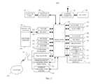
- FIG. 1is a block diagram of a wireless communication system 100 in accordance with various aspects described herein.
- the system 100can include a wireless device 101 , a base station 102 , a satellite 125 , an access point 126 , another wireless device 127 , or any combination thereof.
- the wireless device 101can include a processor 103 , which can also be referred to as a co-processor, controller, or other similar term, electrically connected to a memory 104 , input/output devices 105 , a transceiver 106 , a short-range RF communication subsystem 109 , another RF communication subsystem 110 , or any combination thereof, which can be utilized by the wireless device 101 to implement various aspects described herein.
- the processor 103can manage and control the overall operation of the wireless device 101 .
- the transceiver 106 of the wireless device 101can include a transmitter 107 , a receiver 108 , or both. Further, associated with the wireless device 101 , the transmitter 107 , the receiver 108 , the short-range RF communication subsystem 109 , the other RF communication subsystem 110 , or any combination thereof can be electrically connected to an antenna 141 .
- the wireless device 101can be capable of two-way voice communication, two-way data communication, or both including with the base station 102 , the satellite 125 , the access point 126 , the other wireless device 127 , or any combination thereof.
- the voice and data communicationsmay be associated with the same or different networks using, for instance, the same or different base stations 102 .
- the detailed design of the transceiver 106 of the wireless device 101is dependent on the wireless communication system used.
- a text messagefor instance, can be received at the antenna 141 , can be processed by the receiver 108 of the transceiver 106 , and can be provided to the processor 103 .
- the short-range RF communication subsystem 109may also be integrated in the wireless device 101 .
- the short-range RF communication subsystem 109may include a Bluetooth module, a WLAN module, or both.
- the short-range RF communication subsystem 109may use the antenna 141 for transmitting RF signals, receiving RF signals, or both.
- the Bluetooth modulecan use the antenna 141 to communicate, for instance, with the other wireless devices 127 such as a Bluetooth-capable printer.
- the WLAN modulemay use the antenna 141 to communicate with the access point 126 such as a router or other similar device.
- the other RF communication subsystem 110may be integrated in wireless device 101 .
- the other RF communication subsystem 110may include a GPS receiver that uses the antenna 141 of the wireless device 101 to receive information from one or more GPS satellites 125 .
- the other RF communication subsystem 110may use the antenna 141 of the wireless device 101 for transmitting RF signals, receiving RF signals, or both.
- the base station 102can include a processor 113 electrically connected to a memory 114 and a transceiver 116 , which can be utilized by the base station 102 to implement various aspects described herein.
- the transceiver 116 of the base station 102can include a transmitter 117 , a receiver 118 , or both. Further, associated with base station 102 , a transmitter 117 , a receiver 118 , or both can be electrically connected to an antenna 121 .
- the base station 102can communicate with the wireless device 101 on the uplink using the antennas 141 and 121 , and on the downlink using the antennas 141 and 121 , associated with the wireless device 101 and the base station 102 , respectively.
- the uplinkrefers to communication from a wireless device to a base station
- the downlinkrefers to communication from a base station to a wireless device.
- the base station 102can originate downlink information using the transmitter 117 and the antenna 121 , where it can be received by the receiver 108 at the wireless device 101 using the antenna 141 . Such information can be related to a communication link between the base station 102 and the wireless device 101 .
- the wireless device 101can process the received information to generate a response relating to the received information.
- Such responsecan be transmitted back from the wireless device 101 on the uplink using the transmitter 107 and the antenna 141 , and received at the base station 102 using the antenna 121 and the receiver 118 .
- FIG. 2is a block diagram illustrating one embodiment of a wireless device 200 in accordance with various aspects set forth herein.
- the wireless device 200can include a processor 203 electrically connected to, for instance, a transceiver 205 , a decoder 206 , an encoder 207 , a memory 204 , a navigation mechanism 211 , a display 212 , an emitter 213 , a display overlay 214 , a display controller 216 , a touch-sensitive display 218 , an actuator 220 , a sensor 223 , an auxiliary input/output subsystem 224 , a data port 226 , a speaker 228 , a microphone 230 , a short-range communication subsystem 209 , another RF communication subsystem 210 , a subscriber identity module or a removable user identity module (“SIM/RUIM”) interface 240 , a battery interface 242 , other component, or any combination thereof.
- the navigation mechanism 211can be, for instance
- the processor 203can control and perform various functions associated with the control, operation, or both of the wireless device 200 .
- the wireless device 200can be powered by, for instance, the battery 244 , an alternating current (“AC”) source, another power source, or any combination thereof.
- the wireless device 200can use, for instance, the battery interface 242 to receive power from the battery 244 .
- the battery 244can be, for instance, a rechargeable battery, a replaceable battery, or both.
- the processor 203can control the battery 244 via the battery interface 242 .
- the wireless device 200can perform communication functions, including data communication, voice communication, video communication, other communication, or any combination thereof using, for instance, the processor 203 electrically connected to the auxiliary input/output subsystem 224 , the data port 226 , the transceiver 205 , the short-range communication subsystem 209 , the other RF communication subsystem 210 , or any combination thereof.
- the wireless device 200can communicate between, for instance, the network 250 .
- the network 250may be comprised of, for instance, a plurality of wireless devices and a plurality of infrastructure equipment.
- the display controller 216can be electrically connected to the display overlay 214 , display 212 , or both.
- the display overlay 214 and the display 212can be electrically connected to the display controller 216 to form, for instance, the touch-sensitive display 218 .
- the touch-sensitive display 218can also be referred to as a touch-screen display, touch-screen monitor, touch-screen terminal, or other similar term.
- the processor 203can directly control display overlay 214 , indirectly control display overlay 214 using display controller 216 , or both.
- the processor 203can display, for instance, an electronic document stored in the memory 210 on the display 212 , the touch-sensitive display 218 , or both of the wireless device 200 .
- the wireless device 200can include the sensor 223 , which can be electrically connected to the processor 203 .
- the sensor 223can be, for instance, an accelerometer sensor, a tilt sensor, a force sensor, an optical sensor, or any combination thereof. Further, the sensor 223 may comprise multiple sensors which are the same or different.
- the sensor 223can include an accelerometer sensor and an optical sensor.
- An accelerometer sensormay be used, for instance, to detect the direction of gravitational forces, gravity-induced reaction forces, or both. Further, the accelerometer sensor may be used to detect the placement of the wireless device 200 in various directional alignments such as a horizontal directional alignment.
- the accelerometer sensormay include, for instance, a cantilever beam with a proof mass and suitable deflection sensing circuitry.
- the optical sensorcan be the same or similar to the sensor used in, for instance, a desktop mouse.
- the optical sensorcan be, for instance, a camera lens.
- the processor 203may be configured to process contiguous images captured by the camera lens and use such images to detect the direction, distance, or both of the wireless device 100 relative to an object, surface, or user.
- the processor 203may be configured to process contiguous images captured by the camera lens and use such images to detect a user of the wireless device 200 placing such device, for instance, against the user's ear.
- the wireless device 200may include the subscriber identity module or a removable user identity module (“SIM/RUIM”) card 238 .
- SIM/RUIMcan contain, for instance, user identification information, which can be used to allow access to network 250 for the user of the wireless device 200 .
- the SIM/RUIM card 238can be electrically connected to the SIM/RUIM interface 240 , wherein the processor 203 can control the SIM/RUIM card 238 via the SIM/RUIM interface 240 .
- the user identification informationmay also be stored in the memory 204 and accessed by the processor 203 .
- the wireless device 200can include an operating system 246 and software modules 248 , which may be stored in a computer-readable medium such as the memory 204 .
- the memory 204can be, for instance, RAM, static RAM (“SRAM”), dynamic RAM (“DRAM”), read only memory (“ROM”), volatile memory, non-volatile memory, cache memory, hard drive memory, virtual memory, other memory, or any combination thereof.
- the processor 203can execute program instructions stored in the memory 204 associated with the operating system 246 , the software modules 248 , other program instructions, or combination of program instructions.
- the processor 203may load the operating system 246 , the software modules 248 , data, an electronic document, or any combination thereof into the memory 204 via the transceiver 205 , the auxiliary I/O subsystem 224 , the data port 226 , the short-range RF communications subsystem 209 , the other RF communication subsystem 210 , or any combination thereof.
- FIG. 3illustrates a block diagram of one embodiment of a beamforming antenna system 300 for a wireless device in accordance with various aspects set forth herein.
- the system 300can include a beamforming antenna 341 , an adaptive matching network 342 , a transceiver 305 , a usage detector 344 , a sensor 323 , a controller 303 , a switching circuit 347 , other element, or any combination thereof.
- the beamforming antenna 341can include a primary radiating element with one or more reconfigurable parasitic elements.
- the beamforming antenna 341can shape and direct an electromagnetic antenna-pattern beam radiated from the beamforming antenna 341 to, for instance, improve the quality of a transmitted signal, received signal, or both.
- the beamforming antenna 341can adaptively steer the antenna-pattern beam towards a base station while traveling throughout the coverage area of such base station. Further, the beamforming antenna 341 can direct the antenna-pattern beam away from a user of the associated wireless device to reduce the amount of electromagnetic energy absorbed by such user. Also, by directing the antenna-pattern beam of the beamforming antenna 341 towards a receiving antenna such as at a base station can reduce the amount of co-channel or adjacent channel interference received by other wireless devices. By more effectively and efficiently receiving RF signals, radiating RF signals, or both, the wireless device using the beamforming antenna 341 can achieve better performance with lower average power consumption.
- the steering of the antenna-pattern beamcan be performed using, for instance, switching elements associated with the switching circuit 347 to select reconfigurable parasitic elements of the beamforming antenna 341 .
- the selected parasitic elements and the primary radiating elementcan cooperatively receive and radiate RF signals.
- the beamforming antenna 341can be electrically connected to the adaptive matching network 342 , which can be used in, for instance, real time, near-real time, non-real time, periodically, aperiodically, or any combination thereof to match the input impedance of the beamforming antenna 341 to improve the power transfer and reduce reflections from the beamforming antenna 341 .
- the adaptive matching network 342can be used in, for instance, real time, near-real time, non-real time, periodically, aperiodically, or any combination thereof to estimate the input impedance of the beamforming antenna 341 .
- the transceiver 305can include a transmitter, a receiver, or both.
- the input to the transceiver 305can be an RF signal, which has been converted from an electromagnetic signal to an electrical signal via the beamforming antenna 341 .
- the output of the transceiver 305can be a baseband signal or an intermediate frequency (“IF”) signal.
- IFintermediate frequency
- the input to the transceiver 305can be an RF signal, which can be converted from an electromagnetic signal to an electrical signal via the beamforming antenna 341 .
- the output of the transceiver 305can be a baseband signal or an intermediate frequency (“IF”) signal.
- the input to the transceiver 305can be a baseband signal or an IF signal.
- the output of the transceiver 305can be an RF signal, which can be converted from an electrical signal to an electromagnetic signal by the beamforming antenna 341 .
- the detailed design of the transceiver 305is dependent on, for instance, the wireless communication system used.
- the usage detector 344can be used to determine, for instance, the orientation, the operating mode, the operating environment, or any combination thereof of the wireless device, which may be used to determine to update the beamforming antenna 341 , adapt the antenna-pattern beam of the beamforming antenna 341 , or both.
- the usage detector 344can receive, for instance, a signal from the adaptive matching network 342 , a signal from the transceiver 305 , a signal from the sensor 323 , other signal, or any combination thereof.
- the usage detector 344can determine the operating environment of the wireless device by identifying a change in, for instance, the received signal strength of the beamforming antenna 341 ; the directional alignment of the wireless device using, for instance, an accelerometer; the propagation characteristics of a received signal; the input impedance of the beamforming antenna 341 ; other information; or any combination thereof.
- the usage detector 344can determine that the wireless device is placed against a user's ear during a voice call using the call processing state of the wireless device, the directional alignment of the wireless device, a change in the input impedance of the beamforming antenna 341 , other factor, or any combination thereof.
- the usage detector 344can receive a signal from the sensor 323 indicating that the wireless device is in a substantially horizontal directional alignment consistent with the positioning of the wireless device by a user during a voice call.
- the controller 303can provide the usage detector 344 with, for instance, the call processing state of the wireless device such as a voice call state.
- the usage detector 344can monitor for a change in the input impedance of the beamforming antenna 341 using the adaptive matching network 342 , which may be used to determine, for instance, that a wireless device is close to the user's body. After determining, for instance, that the wireless device is placed against a user's ear during a voice call, the controller 303 can switch one or more reconfigurable parasitic elements of the beamforming antenna 341 to steer the antenna-pattern beam away from the user's body.
- the controller 303can determine to update the antenna-pattern beam of the beamforming antenna 341 by using, for instance, a change in the received signal strength of the beamforming antenna 341 , the directional alignment of the wireless device, the propagation characteristics of a received signal via the beamforming antenna 341 , the input impedance of the beamforming antenna 341 using the adaptive matching network 342 , or any combination thereof.
- the controller 303can measure a plurality of received signal strengths of the beamforming antenna 341 , wherein each measurement can correspond to the primary radiating element with one or more different reconfigurable parasitic elements. Further, the controller 303 can determine to steer the beamforming antenna 341 by, for instance, comparing one or more of such received signal strengths to the received signal strength of the currently configured beamforming antenna.
- FIG. 4illustrates a block diagram of another embodiment of a beamforming antenna system 400 for a wireless device in accordance with various aspects set forth herein.
- the system 400can include a beamforming antenna 441 , an adaptive matching network 442 , a transceiver 405 , a usage detector 444 , a sensor 423 , a controller 403 , a switching circuit 447 , other element, or any combination thereof.
- the beamforming antenna 441can include a primary radiating element 450 with one or more secondary parasitic elements 451 a to 451 e .
- the primary radiating element 450is a dipole.
- each of the reconfigurable parasitic elements 451 a to 451 eis a dipole.
- the primary radiating element and the reconfigurable parasitic elementsare monopoles. It is important to recognize that the primary radiating element and any combination of the reconfigurable parasitic elements form a beamforming antenna, which can radiate with specific characteristics. Further, the primary radiating element and any combination of the reconfigurable parasitic elements can be electrically connected, electrically coupled, or both. Therefore, the primary radiating element and any combination of the reconfigurable parasitic elements can be physically connected or not physically connected.
- a dipole antennais an omnidirectional radio antenna with a center-fed driven element, which can be made of, for instance, a simple copper wire.
- a monopole antennais an omnidirectional antenna formed by replacing one half of a dipole antenna with a ground plane at a substantially perpendicular angle to the monopole, wherein the monopole can behave like a dipole if the ground plane is sufficiently large.
- the length of a radiating element such as a monopolecan typically be as short as about one-quarter the wavelength of the desired resonant frequency.
- the length of a radiating element of the present disclosureis not limited to one-quarter the wavelength of the desired resonant frequency, but other lengths may be chosen, such as one-half the wavelength of the desired resonant frequency.
- the length of a radiating element such as a dipolecan typically be as short as about one-half the wavelength of the desired resonant frequency.
- the beamforming antenna 441can direct an electromagnetic antenna-pattern beam 461 a to 461 e radiated from the beamforming antenna 441 to improve the quality of a transmitted signal, received signal, or both.
- the beamforming antenna 441can adaptively steer the antenna-pattern beam 461 a to 461 e towards, for instance, a base station while traveling throughout the coverage area of the base station.
- the controller 403selects the parasitic element 451 a .
- the primary radiating element 450 and the parasitic element 451 acooperatively transmit an antenna-pattern beam in the direction consistent with the antenna-pattern beam 461 a .
- the controller 403does not select any reconfigurable parasitic elements 451 a to 451 e .
- the primary radiating element 450provides an omnidirectional beam.
- the controller 403selects the reconfigurable parasitic elements 451 a and 451 b .
- the primary radiating element 450 and the reconfigurable parasitic elements 451 a and 451 bprovide an antenna-pattern beam in the direction between the antenna-pattern beams 461 a and 461 b .
- the beamforming antenna 441can direct the antenna-pattern beam 461 a to 461 e away from a user of the associated wireless device to reduce the amount of electromagnetic energy absorbed by such user.
- the wireless device using the beamforming antenna 441can achieve better performance and lower power consumption.
- any combination of reconfigurable parasitic elementscan be used in conjunction with the primary radiating element.
- any number of primary and reconfigurable parasitic elementscan be used. For example, two primary radiating elements can be used to provide, for instance, polarization diversity. Further, six reconfigurable parasitic elements can be used in conjunction with the two primary radiating elements to cooperatively provide an antenna-pattern beam in a predetermined direction.
- the adaptive steering of the antenna-pattern beamcan be performed using, for instance, switching elements associated with the switching circuit 447 to select parasitic elements 451 a and 451 b of the beamforming antenna 441 .
- the selected parasitic elements 451 a and 451 b and the primary radiating element 450can cooperatively receive and radiate RF signals.
- a plurality of reconfigurable parasitic elements 451 a and 451 bsuch as monopoles, dipoles, or both can be contiguously and uniformly distributed around a primary radiating element 450 .
- Such parasitic elements 451 a and 451 bcan be adaptively switched to cooperatively work with the primary radiating element 450 to adaptively steer the antenna-pattern beam.
- the beamforming antenna configurations described by this disclosuremay also provide polarization diversity, frequency diversity, multiband operation, broadband operation, or any combination thereof. Further, a person of ordinary skill in the art will recognize that there are many different antenna systems, structures, and configurations, which may support a beamforming function as described in this disclosure.
- the beamforming antenna 441can be electrically connected to the adaptive matching network 442 , which can be used to match the input impedance of the beamforming antenna 441 , for instance, after switching to the desired parasitic element or elements is made to improve the power transfer and reduce reflections from the beamforming antenna 441 .
- the adaptive matching network 442can be used to estimate the input impedance of the beamforming antenna 441 .
- the transceiver 405can include a transmitter, a receiver, or both. On the downlink, the input to the transceiver 405 can be an RF signal, which can be converted from an electromagnetic signal to an electrical signal via the beamforming antenna 441 .
- the output of the transceiver 405can be a baseband signal or an intermediate frequency (“IF”) signal.
- the input to the transceiver 405can be a baseband signal or an IF signal.
- the output of the transceiver 405can be an RF signal, which can be converted from an electrical signal to an electromagnetic signal by the beamforming antenna 441 .
- the detailed design of the transceiver 405is dependent on the wireless communication system used.
- the usage detector 444can be used to determine the operating environment of the wireless device, which may be used to further adapt or control the antenna-pattern beam of the beamforming antenna 441 .
- the usage detector 444can receive a signal from the adaptive matching network 442 , a signal from the transceiver 405 , a signal from the sensor 423 , other signal, or any combination thereof.
- the usage detector 444can determine the operating environment of the wireless device by identifying a change in, for instance, the received signal strength of the beamforming antenna 441 ; the directional alignment of the wireless device; the propagation characteristics of a received signal; the input impedance of the beamforming antenna 441 ; other information; or any combination thereof.
- the usage detector 444can determine that the wireless device is placed against a user's ear during a voice call using the call processing state of the wireless device, the directional alignment of the wireless device, a change in the input impedance of the beamforming antenna 441 , other factor, or any combination thereof.
- the usage detector 444can receive a signal from the sensor 423 indicating that the wireless device is in a substantially horizontal directional alignment consistent with the positioning of the wireless device by a user during a voice call.
- the controller 403can provide the usage detector 444 with, for instance, the call processing state of the wireless device such as a voice call state.
- the usage detector 444can monitor for a change in the input impedance of the beamforming antenna 441 using the adaptive matching network 442 , which may be used to determine, for instance, that a wireless device is close to the user's body. After determining that the wireless device is placed against a user's ear during a voice call, the controller 403 can switch one or more reconfigurable parasitic elements 451 a and 451 b of the beamforming antenna 441 to steer the antenna-pattern beam away from the user's body.
- the controller 403can determine to update the antenna-pattern beam of the beamforming antenna 441 by using, for instance, a change in the received signal strength of the beamforming antenna 441 ; the directional alignment of the wireless device; the propagation characteristics of a received signal via the beamforming antenna 441 ; the input impedance of the beamforming antenna 441 using the adaptive matching network 442 ; or any combination thereof.
- the controller 403can measure a plurality of received signal strengths for the beamforming antenna 441 , wherein each measurement can correspond to the primary radiating element 450 with one or more different reconfigurable parasitic elements 451 a and 451 b .
- the controller 403can determine to adaptively steer the beamforming antenna 441 by, for instance, comparing one or more of such received signal strengths to the received signal strength of the currently configured beamforming antenna. If one or more of such received signal strengths is sufficiently greater than the received signal strength of the currently configured beamforming antenna, then the controller 403 can switch to the one or more reconfigurable parasitic elements 451 a and 451 b corresponding to the greater received signal strength by using the switching circuit 447 .
- FIG. 5illustrates a block diagram of another embodiment of a beamforming antenna system 500 for a wireless device in accordance with various aspects set forth herein.
- the system 500can include a beamforming antenna 541 , an adaptive matching network 542 , a transceiver 505 , a usage detector 544 , a sensor 523 , a controller 503 , a switching circuit 547 , other element, or any combination thereof.
- the beamforming antenna 541can include a primary radiating element 552 with one or more reconfigurable parasitic elements 553 a to 553 e .
- the primary radiating element 552is a patch antenna.
- each of the reconfigurable parasitic elements 553 a to 553 eis a radiating strip or patch element.
- a patch antennatypically is a miniaturized antenna radiating structure, such as a planar inverted-F antenna (“PIFA”).
- PIFAplanar inverted-F antenna
- Patch antennasare popular for use in wireless devices due to their low profile, ability to conform to surface profiles, and unlimited shapes and sizes.
- Patch antenna polarizationcan be linear or elliptical, with a main polarization component parallel to the surface of the patch antenna. Operating characteristics of patch antennas are predominantly established by their shape and dimensions.
- the patch antennais typically fabricated using printed-circuit techniques and integrated with a printed circuit board (“PCB”).
- PCBprinted circuit board
- the patch antennais typically electrically coupled to a ground area, wherein the ground area is typically formed on or in a PCB.
- Patch antennasare typically spaced from and parallel to the ground area and are typically located near other electronic components, ground planes, and signal traces, which may impact the design and performance of the antenna.
- patch antennasare typically considered to be lightweight, compact, and relatively easy to manufacture and integrate into a wireless device.
- a patch antenna designcan include one or more slots in the antenna's radiating member. Selection of the position, shape, contour, and length of a slot depends on the design requirements of the particular patch antenna.
- the function of a slot in a patch antenna designincludes physically partitioning the radiating member of a single-band patch antenna into a subset of radiating members for multiple-band operation, providing reactive loading to modify the resonant frequencies of a radiating member, and controlling the polarization characteristics of a multiple-band patch antenna.
- radiating members of a patch antennacan have stub members, usually consisting of a tab at the end of a radiating member. The function of a stub member includes providing reactive loading to modify the resonant frequencies of a radiating member.
- the beamforming antenna 541can direct an electromagnetic beam radiated from the beamforming antenna 541 to improve the quality of a transmitted signal, received signal, or both. For example, the beamforming antenna 541 can steer the antenna-pattern beam towards a base station while traveling throughout the coverage area of the base station. Further, the beamforming antenna 541 can direct the antenna-pattern beam away from a user of the associated wireless device to reduce the amount of electromagnetic energy absorbed by such user. Also, by directing the antenna-pattern beam of the beamforming antenna 541 towards a receiving antenna such as at a base station can reduce the amount of interference received by other wireless devices. By more effectively and efficiently receiving RF signals, radiating RF signals, or both, the wireless device using the beamforming antenna 541 can achieve lower power consumption.
- the steering of the antenna-pattern beamcan be performed using, for instance, switching elements associated with the switching circuit 547 to select reconfigurable parasitic elements of the beamforming antenna 541 .
- the selected parasitic elements and the primary radiating elementcan cooperatively receive and radiate RF signals.
- a plurality of radiating strip elements 553 a to 553 ecan be adaptively switched to cooperatively work with the patch antenna 552 to steer the antenna-pattern beam. It is important to recognize that the aforementioned beamforming antenna configurations may also provide polarization diversity, frequency diversity, multiband operation, broadband operation, or any combination thereof.
- the beamforming antenna 541can be electrically connected to the adaptive matching network 542 , which can be used to match the input impedance of the beamforming antenna 541 to improve the power transfer and reduce reflections from the beamforming antenna 541 .
- the adaptive matching network 542can be used to estimate the input impedance of the beamforming antenna 541 .
- the transceiver 505can include a transmitter, a receiver, or both. On the downlink, the input to the transceiver 505 can be an RF signal, which can be converted from an electromagnetic signal to an electrical signal via the beamforming antenna 541 .
- the output of the transceiver 505can be a baseband signal or an intermediate frequency (“IF”) signal.
- the input to the transceiver 505can be a baseband signal or an IF signal.
- the output of the transceiver 505can be an RF signal, which can be converted from an electrical signal to an electromagnetic signal by the beamforming antenna 541 .
- the detailed design of the transceiver 505is dependent on the wireless communication system used.
- the usage detector 544can be used to determine the operating environment of the wireless device, which may be used to further adapt the antenna-pattern beam of the beamforming antenna 541 .
- the usage detector 544can receive a signal from the adaptive matching network 542 , a signal from the transceiver 505 , a signal from the sensor 523 , other signal, or any combination thereof.
- the usage detector 544can determine the operating environment of the wireless device by identifying a change in, for instance, the received signal strength of the beamforming antenna 541 ; the directional alignment of the wireless device, the propagation characteristics of a received signal; the input impedance of the beamforming antenna 541 ; other information; or any combination thereof.
- the usage detector 544can determine that the wireless device is placed against a user's ear during a voice call using the call processing state of the wireless device, the directional alignment of the wireless device, a change in the input impedance of the beamforming antenna 541 , other factor, or any combination thereof.
- the usage detector 544can receive a signal from the sensor 523 indicating that the wireless device is in a substantially horizontal directional alignment consistent with the positioning of the wireless device by a user during a voice call.
- the controller 503can provide the usage detector 544 with, for instance, the call processing state of the wireless device such as a voice call state.
- the usage detector 544can monitor for a change in the input impedance of the beamforming antenna 541 using the adaptive matching network 542 , which may be used to, for instance, initiate the adaptive beam steering operation after determining that a wireless device is close to the user's body.
- the controller 503can switch one or more radiating strip elements 553 a to 553 e of the beamforming antenna 541 to steer the antenna-pattern beam away from the user's body.
- the controller 503can determine to update the antenna-pattern beam of the beamforming antenna 541 by using, for instance, a change in the received signal strength of the beamforming antenna 541 , the directional alignment of the wireless device, the propagation characteristics of a received signal via the beamforming antenna 541 , the input impedance of the beamforming antenna 541 using the adaptive matching network 542 , or any combination thereof.
- the controller 503can measure a plurality of received signal strengths for the beamforming antenna 541 , wherein each measurement can correspond to the primary radiating element with one or more different reconfigurable parasitic elements. Further, the controller 503 can determine to steer the beamforming antenna 541 by, for instance, comparing one or more of such received signal strengths to the received signal strength of the currently configured beamforming antenna.
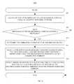
- FIG. 6is a flow chart of one embodiment of a method 600 of adapting a beamforming antenna using reconfigurable parasitic elements in accordance with various aspects set forth herein.
- the method 600can start at block 681 , where the method 600 can calculate the input impedance of the beamforming antenna using an adaptive matching network, wherein the adaptive matching network is electrically connected to the beamforming antenna.
- the method 600can determine whether the input impedance of the beamforming antenna is outside a tolerance.
- the tolerancecan reflect the variability of the input impedance of the beamforming antenna while in a static environment. For instance, the tolerance can be correlated to the variance of the input impedance of the beamforming antenna while in a specific environment.
- the quality of the design of the beamforming antenna, the quality of the components used for the beamforming antenna, environmental conditions, other factor, or any combination thereofmay impact the tolerance of the beamforming antenna.
- the method 600can determine the operating environment of the wireless device using, for instance, the received signal strength of the beamforming antenna, the propagation characteristics of a received signal via the beamforming antenna, the input impedance of the beamforming antenna, the speed of the wireless device, the delay spread of signals received at the beamforming antenna, the directional alignment of the wireless device, other factor, or any combination thereof.
- the method 600can use a sensor such as an accelerometer to determine, for instance, the directional alignment of the wireless device, the speed of the wireless device, the acceleration of the wireless device, other factor, or any combination thereof.
- the method 600can use a sensor such as a camera to monitor contiguous images to determine whether the wireless device is placed against or near a user's ear.
- the method 600can select a set of one or more reconfigurable parasitic elements using, for instance, the input impedance, a predetermined input impedance observation table, the recognized operating environment, other factor, or any combination thereof. For example, the method 600 can compare the measured input impedance of the beamforming antenna to entries in the predetermined input impedance observation table to select one or more reconfigurable parasitic elements.
- the predetermined input impedance observation tablecan be derived by capturing the measurements of the input impedance of the beamforming antenna under various environments and conditions.
- the various environments and conditionscan be, for instance, the presence of a user or an object near the beamforming antenna of a wireless device; an RF signal transmitted from a specific direction towards the beamforming antenna of a wireless device; the propagation environment; other condition or environment; or any combination thereof.
- the method 600can update the beamforming antenna by electrically connecting, electrically coupling, or both the set of one or more reconfigurable parasitic elements with the primary radiating element.
- the input impedance matching of the beamforming antenna formed by the primary radiating element electrically connected, electrically coupled, or both to one or more selected parasitic elementscan be adaptively optimized for maximum power transfer using the calculated impedance value.
- FIG. 7is a flow chart of one embodiment of a method 700 of adapting a beamforming antenna using reconfigurable parasitic elements in accordance with various aspects set forth herein.
- the method 700can start at block 781 , where the method 700 can calculate the input impedance of the beamforming antenna using an adaptive matching network, wherein the adaptive matching network is electrically connected to the beamforming antenna.
- the method 700can determine whether the input impedance of the beamforming antenna is outside a tolerance.
- the tolerancecan reflect the variability of the input impedance of the beamforming antenna while in, for instance, a static environment.
- the tolerancecan be correlated to the variance of the input impedance of the beamforming antenna while in a specific environment.
- the quality of the design of the beamforming antenna, the quality of the components used for the beamforming antenna, environmental conditions, other factor, or any combination thereofmay impact the tolerance of the beamforming antenna.
- the method 700can determine the operating environment of the wireless device using, for instance, the received signal strength of the beamforming antenna, the propagation characteristics of a received signal via the beamforming antenna, the input impedance of the beamforming antenna, the speed of the wireless device, the delay spread of signals received at the beamforming antenna, the directional alignment of the wireless device, other factor, or any combination thereof.
- the method 700can use a sensor such as an accelerometer to determine, for instance, the directional alignment of the wireless device, the speed of the wireless device, the acceleration of the wireless device, other factor, or any combination thereof.
- the method 700can use a sensor such as a camera to monitor contiguous images to determine whether the wireless device is placed against or near a user's ear.
- the method 700can select a portion of one or more reconfigurable parasitic elements using, for instance, the input impedance, a predetermined input impedance observation table, the recognized operating environment, other factor, or any combination thereof. For example, the method 700 can compare the measured input impedance of the beamforming antenna to entries in the predetermined input impedance observation table to select one or more reconfigurable parasitic elements.
- the predetermined input impedance observation tablecan be derived by capturing the measurements of the input impedance of the beamforming antenna under various environments and conditions. The various environments and conditions can be, for instance, the presence of a user or an object; an RF signal transmitted from a specific direction towards the beamforming antenna; the propagation environment; other condition; or any combination thereof.
- the method 700can calculate the input impedance of the beamforming antenna for each of the portion of reconfigurable parasitic elements using the adaptive matching network.
- the method 700can determine whether to consider more than one parasitic element configuration using the input impedance calculated at block 785 . If more than one parasitic element configuration is considered, then at block 787 the method 700 can calculate the received signal strength of the beamforming antenna for the primary radiating element with any combination of the parasitic element configurations.
- the method 700can select one or more of the parasitic element configurations having the largest received signal strength.
- the method 700can update the beamforming antenna by electrically connecting, electrically coupling, or both the selected parasitic element configuration or configurations with the primary radiating element by using, for instance, a switching circuit.
- the input impedance match of the antenna formed by the primary radiating element electrically connected, electrically coupled, or both to one or more of the selected parasitic elementscan be adaptively updated to improve the power transfer of the beamforming antenna by using the adaptive matching network to calculate the input impedance value.
- FIG. 8is a flow chart of another embodiment of a method 800 of adapting a beamforming antenna using reconfigurable parasitic elements in accordance with various aspects set forth herein.
- the method 800can start at block 881 , where the method 800 can calculate the input impedance of the beamforming antenna using an adaptive matching network, wherein the adaptive matching network is electrically connected to the beamforming antenna.
- the method 800can determine whether the input impedance of the beamforming antenna is outside a tolerance.
- the tolerancecan reflect the variability of the input impedance of the beamforming antenna while in a static environment. For instance, the tolerance can be correlated to the variance of the input impedance of the beamforming antenna while in a specific environment.
- the quality of the design of the beamforming antenna, the quality of the components used for the beamforming antenna, environmental conditions, other factor, or any combination thereofmay impact the tolerance of the beamforming antenna.
- the method 800can determine the operating environment of the wireless device using, for instance, the received signal strength of the beamforming antenna, the propagation characteristics of a received signal via the beamforming antenna, the input impedance of the beamforming antenna, the speed of the wireless device, the delay spread of signals received at the beamforming antenna, the directional alignment of the wireless device, other factor, or any combination thereof.
- the method 800can use a sensor such as an accelerometer to determine, for instance, the directional alignment of the wireless device, the speed of the wireless device, the acceleration of the wireless device, other factor, or any combination thereof.
- the method 800can use a sensor such as a camera to monitor contiguous images to determine whether the wireless device is placed against or near a user's ear.
- the method 800can select a set of one or more reconfigurable parasitic elements using, for instance, the input impedance, a predetermined input impedance observation table, the recognized operating environment, other factor, or any combination thereof. For example, the method 800 can compare the measured input impedance of the beamforming antenna to entries in the predetermined input impedance observation table to select one or more reconfigurable parasitic elements.
- the predetermined input impedance observation tablecan be derived by capturing the measurements of the input impedance of the beamforming antenna under various environments and conditions.
- the various environments and conditionscan be, for instance, the presence of a user or an object; an RF signal transmitted from a specific direction towards the beamforming antenna; the propagation environment of the wireless device; other condition; or any combination thereof.
- the method 800can update the beamforming antenna by electrically connecting, electrically coupling, or both the set of one or more reconfigurable parasitic elements with the primary radiating element.
- the method 800can re-calculate the input impedance of the updated beamforming antenna using, for instance, the adaptive matching network.
- the method 900can then match the adaptive matching network to about the same calculated input impedance of the updated beamforming antenna.
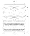
- FIG. 9is a flow chart of another embodiment of a method 900 of adapting a beamforming antenna using reconfigurable parasitic elements in accordance with various aspects set forth herein.
- the method 900can start at block 980 , where the method 900 can determine whether to update the beamforming antenna by, for instance, determining a change in the received signal strength of the beamforming antenna, the directional alignment of the wireless device, the propagation characteristics of a received signal via the beamforming antenna, the input impedance of the beamforming antenna, or any combination thereof.
- the method 900can measure a plurality of received signal strengths of the beamforming antenna, wherein each measurement corresponds to a primary radiating element of the beamforming antenna with one or more different reconfigurable parasitic elements.
- the method 900can determine to update the beamforming antenna by determining whether one of the plurality of received signal strengths corresponding to a specific configuration of one or more reconfigurable parasitic elements with the primary radiating element is greater than the received signal strength of the currently configured beamforming antenna. If one of the plurality of received signal strengths is greater than the received signal strength of the currently configured beamforming antenna, then the method 900 can update the beamforming antenna.
- the method 900can calculate the input impedance of the beamforming antenna using an adaptive matching network, wherein the adaptive matching network is electrically connected to the beamforming antenna.
- the method 900can determine whether the input impedance of the beamforming antenna is outside a tolerance.
- the tolerancecan reflect the variability of the input impedance of the beamforming antenna while in a specific environment such as a static environment. For instance, the tolerance can be correlated to the variance of the input impedance of the beamforming antenna while in a specific environment.
- the quality of the design of the beamforming antenna, the quality of the components used for the beamforming antenna, environmental conditions, other factor, or any combination thereofmay impact the tolerance of the beamforming antenna.
- the method 900can determine the operating environment of the wireless device using, for instance, the received signal strength, the propagation characteristics of the received signal, the input impedance of the beamforming antenna, the speed of the wireless device, the delay spread of signals received at the beamforming antenna, the directional alignment of the wireless device, other factor, or any combination thereof.
- the method 900can use a sensor such as an accelerometer to determine, for instance, the directional alignment of the wireless device, the speed of the wireless device, the acceleration of the wireless device, other factor, or any combination thereof.
- the method 900can use a sensor such as a camera to monitor contiguous images to determine whether the wireless device is placed against or near a user's ear.
- the method 900can select a portion of one or more reconfigurable parasitic elements using, for instance, the measured input impedance of the beamforming antenna, a predetermined input impedance observation table, the recognized operating environment, other factor, or any combination thereof.
- the method 900can compare the measured input impedance of the beamforming antenna to entries in the predetermined input impedance observation table to select the set of one or more reconfigurable parasitic elements.
- the predetermined input impedance observation tablecan be derived by capturing the measurements of the input impedance of the beamforming antenna under various environments and conditions.
- the various environments and conditionscan be, for instance, the presence of a user or an object; an RF signal transmitted from a specific direction towards the beamforming antenna; the propagation environment of the wireless device; other condition; or any combination thereof.
- the method 900can update the beamforming antenna by electrically connecting, electrically coupling, or both the set of one or more reconfigurable parasitic elements with the primary radiating element.
- FIG. 10illustrates a block diagram of another embodiment of a beamforming antenna system 1000 for a wireless device in accordance with various aspects set forth herein.
- the system 1000can include a beamforming antenna 1041 , an adaptive matching network 1042 , a transceiver 1005 , a usage detector 1044 , a sensor 1023 , a controller 1003 , a switching circuit 1047 , other element, or any combination thereof.
- the beamforming antenna 1041can include a primary radiating element 1050 with a reconfigurable parasitic elements 1051 .
- the primary radiating element 1050is a monopole or a dipole
- the reconfigurable parasitic element 1051is a monopole or a dipole.
- the beamforming antennacan use the primary radiating element 1050 to generate an omnidirectional antenna-pattern beam 1060 .
- the beamforming antenna 1041can direct the antenna-pattern beam 1061 away from the user to reduce the amount of electromagnetic energy absorbed by such user.
- the directing of the antenna-pattern beam away from a usercan be performed using, for instance, a switching element associated with the switching circuit 1047 to select the parasitic element 1051 of the beamforming antenna 1041 .
- the parasitic element 1051 and the primary radiating element 1050can cooperatively receive and radiate RF signals.
- the beamforming antenna 1041can be electrically connected to the adaptive matching network 1042 , which can be used to match the input impedance of the beamforming antenna 1041 to improve the power transfer and reduce reflections from the beamforming antenna 1041 .
- the adaptive matching network 1042can be used to estimate the input impedance of the beamforming antenna 1041 .
- the transceiver 1005can include a transmitter, a receiver, or both. On the downlink, the input to the transceiver 1005 can be an RF signal, which can be converted from an electromagnetic signal to an electrical signal via the beamforming antenna 1041 .
- the output of the transceiver 1005can be a baseband signal or an intermediate frequency (“IF”) signal.
- the input to the transceiver 1005can be a baseband signal or an IF signal.
- the output of the transceiver 1005can be an RF signal, which can be converted from an electrical signal to an electromagnetic signal by the beamforming antenna 1041 .
- the detailed design of the transceiver 1005is dependent on the wireless communication system used.
- the usage detector 1044can be used to determine the operating environment of the wireless device, which can be used to determine when to switch the parasitic element 1051 of the beamforming antenna 1041 .
- the usage detector 1044can receive a signal from the adaptive matching network 1042 , a signal from the transceiver 1005 , a signal from the sensor 1023 , other signal, or any combination thereof.
- the usage detector 1044can determine the operating environment of the wireless device by identifying a change in, for instance, the received signal strength of the beamforming antenna 1041 ; the directional alignment of the wireless device, the propagation characteristics of a received signal; the input impedance of the beamforming antenna 1041 ; other information; or any combination thereof.
- the usage detector 1044can determine that the wireless device is placed against a user's ear during a voice call using the call processing state of the wireless device, the directional alignment of the wireless device, a change in the input impedance of the beamforming antenna 1041 , other factor, or any combination thereof.
- the usage detector 1044can receive a signal from the sensor 1023 indicating that the wireless device is in a substantially horizontal directional alignment consistent with the positioning of the wireless device by a user during a voice call.
- the controller 1003can provide the usage detector 1044 with, for instance, the call processing state of the wireless device such as a voice call state.
- the usage detector 1044can monitor for a change in the input impedance of the beamforming antenna 1041 using the adaptive matching network 1042 , which may be used to determine, for instance, that a wireless device is close to the user's body. After determining that the wireless device is placed against a user's ear during a voice call, the controller 1003 can switch the parasitic element 1051 of the beamforming antenna 1041 to steer the antenna-pattern beam away from the user's body.
- FIG. 11illustrates simulated results of the performance of one embodiment of a beamforming antenna system 400 in accordance with various aspects set forth herein, wherein the results show the measured input impedance of the beamforming antenna 441 over time for a user operating a wireless device in a voice call.
- the graphical representation in its entiretyis referred to by 1100 .
- the number of the discrete-time sample of the measured input impedance of the beamforming antenna 441is shown on the abscissa 1101 .
- the measured input impedance of the beamforming antenna 441is shown on the ordinate 1102 .
- the graph 1103shows the real values of the measured input impedance of the beamforming antenna 441 .
- the graph 1104shows the imaginary values of the measured input impedance of the beamforming antenna 441 .
- the beamforming antenna 441uses a half-wavelength dipole for the primary radiating element 450 and five half-wavelength dipoles for the reconfigurable parasitic elements 451 a to 451 e .
- Each of the five reconfigurable parasitic elements 451 a to 451 eare one tenth of a wavelength from the primary radiating element 450 .
- the antenna gain of the primary radiating element 450is 1.65 dB and the antenna gain of the primary radiating element coupled with one of the reconfigurable parasitic elements 451 a to 451 e is 4.99 dB.
- the simulationwas performed at a frequency of 900 MHz.
Landscapes
- Engineering & Computer Science (AREA)
- Computer Networks & Wireless Communication (AREA)
- Mobile Radio Communication Systems (AREA)
- Variable-Direction Aerials And Aerial Arrays (AREA)
Abstract
Description
Claims (24)
Priority Applications (5)
| Application Number | Priority Date | Filing Date | Title |
|---|---|---|---|
| US12/820,902US8446318B2 (en) | 2010-06-22 | 2010-06-22 | Controlling a beamforming antenna using reconfigurable parasitic elements |
| EP20100191977EP2403057B1 (en) | 2010-06-22 | 2010-11-19 | Controlling a beamforming antenna using reconfigurable parasitic elements |
| PCT/US2011/041199WO2011163194A1 (en) | 2010-06-22 | 2011-06-21 | Controlling a beamforming antenna using reconfigurable parasitic elements |
| CA2802332ACA2802332C (en) | 2010-06-22 | 2011-06-21 | Controlling a beamforming antenna using reconfigurable parasitic elements |
| CN201180038001.XACN103038940B (en) | 2010-06-22 | 2011-06-21 | Controlling a beamforming antenna using reconfigurable parasitic elements |
Applications Claiming Priority (1)
| Application Number | Priority Date | Filing Date | Title |
|---|---|---|---|
| US12/820,902US8446318B2 (en) | 2010-06-22 | 2010-06-22 | Controlling a beamforming antenna using reconfigurable parasitic elements |
Publications (2)
| Publication Number | Publication Date |
|---|---|
| US20110309980A1 US20110309980A1 (en) | 2011-12-22 |
| US8446318B2true US8446318B2 (en) | 2013-05-21 |
Family
ID=43638635
Family Applications (1)
| Application Number | Title | Priority Date | Filing Date |
|---|---|---|---|
| US12/820,902Active2031-01-29US8446318B2 (en) | 2010-06-22 | 2010-06-22 | Controlling a beamforming antenna using reconfigurable parasitic elements |
Country Status (5)
| Country | Link |
|---|---|
| US (1) | US8446318B2 (en) |
| EP (1) | EP2403057B1 (en) |
| CN (1) | CN103038940B (en) |
| CA (1) | CA2802332C (en) |
| WO (1) | WO2011163194A1 (en) |
Cited By (52)
| Publication number | Priority date | Publication date | Assignee | Title |
|---|---|---|---|---|
| US20140225775A1 (en)* | 2013-02-11 | 2014-08-14 | Intel Mobile Communications GmbH | Radio communication devices and methods for controlling a radio communication device |
| US8831127B2 (en)* | 2012-12-14 | 2014-09-09 | Telefonaktiebolaget L M Ericsson (Publ) | Antenna reconfiguration for MIMO communications when multiplicative noise limited |
| US8842764B2 (en) | 2012-12-14 | 2014-09-23 | Telefonaktiebolaget L M Ericsson (Publ) | Precoder weight selection for MIMO communications when multiplicative noise limited |
| US8891657B2 (en) | 2012-12-14 | 2014-11-18 | Telefonaktiebolaget L M Ericsson(Publ) | Transmission power distribution for MIMO communications when multiplicative noise limited |
| US20160036529A1 (en)* | 2013-03-15 | 2016-02-04 | Bae Systems Plc | Directional multiband antenna |
| US10056679B2 (en) | 2008-03-05 | 2018-08-21 | Ethertronics, Inc. | Antenna and method for steering antenna beam direction for WiFi applications |
| US10084233B2 (en) | 2014-06-02 | 2018-09-25 | Ethertronics, Inc. | Modal antenna array for interference mitigation |
| US10109909B1 (en) | 2012-08-10 | 2018-10-23 | Ethertronics, Inc. | Antenna with proximity sensor function |
| US10116050B2 (en) | 2008-03-05 | 2018-10-30 | Ethertronics, Inc. | Modal adaptive antenna using reference signal LTE protocol |
| US10122516B2 (en) | 2012-11-11 | 2018-11-06 | Ethertronics, Inc. | State prediction process and methodology |
| US10129929B2 (en) | 2011-07-24 | 2018-11-13 | Ethertronics, Inc. | Antennas configured for self-learning algorithms and related methods |
| US10171139B1 (en) | 2016-02-02 | 2019-01-01 | Ethertronics, Inc. | Inter-dwelling signal management using reconfigurable antennas |
| US10219208B1 (en) | 2014-08-07 | 2019-02-26 | Ethertronics, Inc. | Heterogeneous network optimization utilizing modal antenna techniques |
| US10224625B2 (en) | 2012-01-24 | 2019-03-05 | Ethertronics, Inc. | Tunable matching network for antenna systems |
| US10224626B1 (en) | 2015-07-24 | 2019-03-05 | Ethertronics, Inc. | Co-located active steering antennas configured for band switching, impedance matching and unit selectivity |
| US10263326B2 (en) | 2008-03-05 | 2019-04-16 | Ethertronics, Inc. | Repeater with multimode antenna |
| US10313894B1 (en) | 2015-09-17 | 2019-06-04 | Ethertronics, Inc. | Beam steering techniques for external antenna configurations |
| US10355767B2 (en) | 2016-02-02 | 2019-07-16 | Ethertronics, Inc. | Network repeater system |
| US10355363B2 (en) | 2013-03-14 | 2019-07-16 | Ethertronics, Inc. | Antenna-like matching component |
| US10419749B2 (en) | 2017-06-20 | 2019-09-17 | Ethertronics, Inc. | Host-independent VHF-UHF active antenna system |
| US10476541B2 (en) | 2017-07-03 | 2019-11-12 | Ethertronics, Inc. | Efficient front end module |
| US10476155B2 (en) | 2016-11-30 | 2019-11-12 | Ethertronics, Inc. | Active antenna steering for network security |
| US10491282B2 (en) | 2012-12-17 | 2019-11-26 | Ethertronics, Inc. | Communication load balancing using distributed antenna beam steering techniques |
| US10491182B2 (en) | 2017-10-12 | 2019-11-26 | Ethertronics, Inc. | RF signal aggregator and antenna system implementing the same |
| US10511093B2 (en) | 2016-11-28 | 2019-12-17 | Ethertronics, Inc. | Active UHF/VHF antenna |
| US10536920B1 (en) | 2015-01-09 | 2020-01-14 | Ethertronics, Inc. | System for location finding |
| US10535927B2 (en) | 2013-09-30 | 2020-01-14 | Ethertronics, Inc. | Antenna system for metallized devices |
| US10582456B2 (en) | 2017-06-07 | 2020-03-03 | Ethertronics, Inc. | Power control method for systems with altitude changing objects |
| US10587913B2 (en) | 2016-04-22 | 2020-03-10 | Ethertronics, Inc. | RF system for distribution of over the air content for in-building applications |
| US10587438B2 (en) | 2018-06-26 | 2020-03-10 | Avx Antenna, Inc. | Method and system for controlling a modal antenna |
| US10701681B1 (en) | 2019-03-29 | 2020-06-30 | At&T Intellectual Property I, L.P. | Coordinated beam forming for 5G or other next generation network |
| US10868371B2 (en) | 2017-03-24 | 2020-12-15 | Ethertronics, Inc. | Null steering antenna techniques for advanced communication systems |
| US10932284B2 (en) | 2016-02-02 | 2021-02-23 | Ethertronics, Inc. | Adaptive antenna for channel selection management in communications systems |
| US10942243B2 (en) | 2014-03-17 | 2021-03-09 | Ethertronics, Inc. | Method for finding signal direction using modal antenna |
| US10985462B2 (en) | 2016-11-30 | 2021-04-20 | Ethertronics, Inc. | Distributed control system for beam steering applications |
| US11063342B2 (en)* | 2019-09-13 | 2021-07-13 | Motorola Mobility Llc | Parasitic patch antenna for radiating or receiving a wireless signal |
| US11189925B2 (en) | 2019-08-01 | 2021-11-30 | Avx Antenna, Inc. | Method and system for controlling a modal antenna |
| US11223404B2 (en) | 2019-06-24 | 2022-01-11 | Avx Antenna, Inc. | Beam forming and beam steering using antenna arrays |
| US11245206B2 (en) | 2019-03-21 | 2022-02-08 | Avx Antenna, Inc. | Multi-mode antenna system |
| US11283196B2 (en) | 2019-06-28 | 2022-03-22 | Avx Antenna, Inc. | Active antenna system for distributing over the air content |
| US11336025B2 (en) | 2018-02-21 | 2022-05-17 | Pet Technology Limited | Antenna arrangement and associated method |
| US11387577B2 (en) | 2018-11-30 | 2022-07-12 | KYOCERA AVX Components (San Diego), Inc. | Channel quality measurement using beam steering in wireless communication networks |
| US11438036B2 (en) | 2019-11-14 | 2022-09-06 | KYOCERA AVX Components (San Diego), Inc. | Client grouping for point to multipoint communications |
| US11515914B2 (en) | 2020-09-25 | 2022-11-29 | KYOCERA AVX Components (San Diego), Inc. | Active antenna system for distributing over the air content |
| US11637372B2 (en) | 2019-01-31 | 2023-04-25 | KYOCERA AVX Components (San Diego), Inc. | Mobile computing device having a modal antenna |
| US11662758B2 (en) | 2019-03-15 | 2023-05-30 | KYOCERA AVX Components (San Diego), Inc. | Voltage regulator circuit for following a voltage source with offset control circuit |
| US11736154B2 (en) | 2020-04-30 | 2023-08-22 | KYOCERA AVX Components (San Diego), Inc. | Method and system for controlling an antenna array |
| US11742567B2 (en) | 2018-08-14 | 2023-08-29 | KYOCERA AVX Components (San Diego), Inc. | Method and system for controlling a modal antenna |
| US20230282975A1 (en)* | 2022-03-02 | 2023-09-07 | United States Of America As Represented By The Secretary Of The Navy | Hybrid RF Beamforming with Multiport Antenna with Parasitic Array |
| US11824619B2 (en) | 2020-06-15 | 2023-11-21 | KYOCERA AVX Components (San Diego), Inc. | Antenna for cellular repeater systems |
| US11971308B2 (en) | 2020-08-26 | 2024-04-30 | KYOCERA AVX Components Corporation | Temperature sensor assembly facilitating beam steering in a temperature monitoring network |
| US12273153B2 (en) | 2020-03-12 | 2025-04-08 | KYOCERA AVX Components (San Diego), Inc. | System and method for surfacing channel quality indicator (CQI) data associated with a multi-mode antenna |
Families Citing this family (55)
| Publication number | Priority date | Publication date | Assignee | Title |
|---|---|---|---|---|
| US8744384B2 (en) | 2000-07-20 | 2014-06-03 | Blackberry Limited | Tunable microwave devices with auto-adjusting matching circuit |
| US9406444B2 (en) | 2005-11-14 | 2016-08-02 | Blackberry Limited | Thin film capacitors |
| US7711337B2 (en) | 2006-01-14 | 2010-05-04 | Paratek Microwave, Inc. | Adaptive impedance matching module (AIMM) control architectures |
| US7535312B2 (en) | 2006-11-08 | 2009-05-19 | Paratek Microwave, Inc. | Adaptive impedance matching apparatus, system and method with improved dynamic range |
| US7714676B2 (en) | 2006-11-08 | 2010-05-11 | Paratek Microwave, Inc. | Adaptive impedance matching apparatus, system and method |
| US11239829B2 (en)* | 2006-11-18 | 2022-02-01 | Rfmicron, Inc. | Method and apparatus for sensing environmental conditions |
| US10164611B2 (en)* | 2006-11-18 | 2018-12-25 | Rfmicron, Inc. | Method and apparatus for sensing environmental conditions |
| US7917104B2 (en) | 2007-04-23 | 2011-03-29 | Paratek Microwave, Inc. | Techniques for improved adaptive impedance matching |
| US8494588B2 (en)* | 2007-07-06 | 2013-07-23 | Telefonaktiebolaget Lm Ericsson (Publ) | Method and apparatus for improving the performance of a mobile radio communications system by adjusting antenna patterns |
| US7991363B2 (en) | 2007-11-14 | 2011-08-02 | Paratek Microwave, Inc. | Tuning matching circuits for transmitter and receiver bands as a function of transmitter metrics |
| US8072285B2 (en) | 2008-09-24 | 2011-12-06 | Paratek Microwave, Inc. | Methods for tuning an adaptive impedance matching network with a look-up table |
| US9026062B2 (en) | 2009-10-10 | 2015-05-05 | Blackberry Limited | Method and apparatus for managing operations of a communication device |
| US8803631B2 (en) | 2010-03-22 | 2014-08-12 | Blackberry Limited | Method and apparatus for adapting a variable impedance network |
| JP5901612B2 (en)* | 2010-04-20 | 2016-04-13 | ブラックベリー リミテッド | Method and apparatus for managing interference in a communication device |
| US9379454B2 (en) | 2010-11-08 | 2016-06-28 | Blackberry Limited | Method and apparatus for tuning antennas in a communication device |
| US8457698B2 (en)* | 2011-01-05 | 2013-06-04 | Alcatel Lucent | Antenna array for supporting multiple beam architectures |
| US20120202421A1 (en)* | 2011-02-04 | 2012-08-09 | Research In Motion Limited | Mobile wireless communications device to detect movement of an adjacent non-radiating object and associated methods |
| US8712340B2 (en) | 2011-02-18 | 2014-04-29 | Blackberry Limited | Method and apparatus for radio antenna frequency tuning |
| US8655286B2 (en)* | 2011-02-25 | 2014-02-18 | Blackberry Limited | Method and apparatus for tuning a communication device |
| US8594584B2 (en) | 2011-05-16 | 2013-11-26 | Blackberry Limited | Method and apparatus for tuning a communication device |
| WO2013015766A1 (en)* | 2011-07-22 | 2013-01-31 | Research In Motion Limited | Adaptively optimized method and system of parasitic element selection for smart beam steering |
| US9219308B2 (en) | 2011-07-22 | 2015-12-22 | Blackberry Limited | Adaptively optimized method and system of parasitic element selection for smart beam steering |
| EP2740221B1 (en) | 2011-08-05 | 2019-06-26 | BlackBerry Limited | Method and apparatus for band tuning in a communication device |
| US9147935B2 (en)* | 2011-08-10 | 2015-09-29 | Qualcomm Incorporated | Maintenance of mobile device RF beam |
| US8515496B2 (en)* | 2011-12-15 | 2013-08-20 | Amazon Technologies, Inc. | Antenna deployment switching for data communication of a user device |
| CN102710275A (en) | 2012-05-11 | 2012-10-03 | 中兴通讯股份有限公司 | Method for intelligently switching on/off mobile terminal antenna and corresponding mobile terminal |
| US8948889B2 (en) | 2012-06-01 | 2015-02-03 | Blackberry Limited | Methods and apparatus for tuning circuit components of a communication device |
| US9853363B2 (en) | 2012-07-06 | 2017-12-26 | Blackberry Limited | Methods and apparatus to control mutual coupling between antennas |
| US9246223B2 (en) | 2012-07-17 | 2016-01-26 | Blackberry Limited | Antenna tuning for multiband operation |
| US9350405B2 (en) | 2012-07-19 | 2016-05-24 | Blackberry Limited | Method and apparatus for antenna tuning and power consumption management in a communication device |
| US9413066B2 (en) | 2012-07-19 | 2016-08-09 | Blackberry Limited | Method and apparatus for beam forming and antenna tuning in a communication device |
| US9362891B2 (en) | 2012-07-26 | 2016-06-07 | Blackberry Limited | Methods and apparatus for tuning a communication device |
| CN103001006B (en)* | 2012-12-07 | 2016-06-15 | Tcl通讯(宁波)有限公司 | A kind of wideband antenna for mobile phone with passive antenna and mobile phone |
| US9374113B2 (en) | 2012-12-21 | 2016-06-21 | Blackberry Limited | Method and apparatus for adjusting the timing of radio antenna tuning |
| US10404295B2 (en) | 2012-12-21 | 2019-09-03 | Blackberry Limited | Method and apparatus for adjusting the timing of radio antenna tuning |
| US9876562B2 (en) | 2013-01-15 | 2018-01-23 | Empire Technology Development Llc | Beamspace-frequency adaptive processing for satellite communications |
| KR102049772B1 (en)* | 2013-01-15 | 2019-11-28 | 삼성전자 주식회사 | Method and apparatus for measureing signal in beamforming system |
| US9472844B2 (en)* | 2013-03-12 | 2016-10-18 | Intel Corporation | Apparatus, system and method of wireless beamformed communication |
| US20140313080A1 (en)* | 2013-04-19 | 2014-10-23 | Telefonaktiebolaget L M Ericsson | Multi-beam smart antenna for wylan and pico cellular applications |
| US9705183B2 (en) | 2013-06-19 | 2017-07-11 | Intermec Ip Corp. | Wirelessly reconfigurable antenna |
| EP2838210B1 (en)* | 2013-08-15 | 2020-07-22 | Oticon A/s | A Portable electronic system with improved wireless communication |
| US9537217B2 (en) | 2013-09-27 | 2017-01-03 | Blackberry Limited | Broadband capacitively-loaded tunable antenna |
| US9438319B2 (en) | 2014-12-16 | 2016-09-06 | Blackberry Limited | Method and apparatus for antenna selection |
| WO2017008267A1 (en)* | 2015-07-15 | 2017-01-19 | Huawei Technologies Co., Ltd. | Dual polarized electronically steerable parasitic antenna radiator |
| CN107851897A (en)* | 2016-06-17 | 2018-03-27 | 华为技术有限公司 | A kind of antenna |
| EP3482474A4 (en)* | 2016-06-20 | 2020-07-29 | Ami Research&development, LLC | Low frequency rectenna system for wireless charging |
| KR20180059274A (en)* | 2016-11-25 | 2018-06-04 | (주)지엠티 | Beamforming antenna control method for improve transmitting/receiving performance in tdma based wireless communication system, and wireless communication apparatus for performing the same |
| WO2019136317A1 (en)* | 2018-01-05 | 2019-07-11 | Wispry, Inc. | Beam-steerable antenna devices, systems, and methods |
| CN109193156B (en)* | 2018-09-18 | 2021-02-19 | 苏州智汇云祥通信系统有限公司 | Directional diagram reconfigurable sensing antenna |
| WO2021221978A1 (en)* | 2020-04-26 | 2021-11-04 | Arris Enterprises Llc | High-gain reconfigurable antenna |
| CN111430915B (en)* | 2020-04-29 | 2021-04-30 | 电子科技大学 | Array beam forming method based on directional diagram reconstruction unit |
| US12244052B2 (en)* | 2020-06-26 | 2025-03-04 | Motorola Mobility Llc | Communication device having a heat sink antenna |
| CN113055932B (en)* | 2021-03-22 | 2024-10-29 | 上海移远通信技术股份有限公司 | Beam control method, system, equipment and medium |
| US12183138B2 (en)* | 2021-06-30 | 2024-12-31 | KYOCERA AVX Components Corporation | System and method for authenticating identity of a person wearing an earpiece |
| FR3129787B1 (en)* | 2021-12-01 | 2025-02-21 | Commissariat Energie Atomique | Controlled Radiation Antenna System |
Citations (12)
| Publication number | Priority date | Publication date | Assignee | Title |
|---|---|---|---|---|
| US6492942B1 (en) | 1999-11-09 | 2002-12-10 | Com Dev International, Inc. | Content-based adaptive parasitic array antenna system |
| US20030030594A1 (en) | 2001-07-30 | 2003-02-13 | Thomas Larry | Small controlled parasitic antenna system and method for controlling same to optimally improve signal quality |
| US20030210203A1 (en) | 2002-05-09 | 2003-11-13 | Phillips James P. | Sensor-driven adaptive counterpoise antenna system |
| US20050088358A1 (en) | 2002-07-29 | 2005-04-28 | Toyon Research Corporation | Reconfigurable parasitic control for antenna arrays and subarrays |
| US6917338B2 (en)* | 2001-12-06 | 2005-07-12 | Koninklijke Philips Electronics N.V. | Parasitic elements diversity antenna |
| US7057573B2 (en) | 2001-11-07 | 2006-06-06 | Advanced Telecommuications Research Institute International | Method for controlling array antenna equipped with a plurality of antenna elements, method for calculating signal to noise ratio of received signal, and method for adaptively controlling radio receiver |
| US7132989B1 (en)* | 2005-05-04 | 2006-11-07 | Kyocera Wireless Corp. | Apparatus, system, and method for adjusting antenna characteristics using tunable parasitic elements |
| US7180464B2 (en) | 2004-07-29 | 2007-02-20 | Interdigital Technology Corporation | Multi-mode input impedance matching for smart antennas and associated methods |
| EP1804335A1 (en) | 2004-09-30 | 2007-07-04 | Toto Ltd. | Microstrip antenna and high frequency sensor using microstrip antenna |
| US20090066440A1 (en) | 2007-09-11 | 2009-03-12 | Commissariat A L'energie Atomique | Method for automatic impedance matching for a radiofrequency circuit and transmission or reception system with automatic matching |
| US20100302106A1 (en)* | 2009-05-29 | 2010-12-02 | Infineon Technologies Ag | Impedance Tuning of Transmitting and Receiving Antennas |
| US7872574B2 (en) | 2006-02-01 | 2011-01-18 | Innovation Specialists, Llc | Sensory enhancement systems and methods in personal electronic devices |
- 2010
- 2010-06-22USUS12/820,902patent/US8446318B2/enactiveActive
- 2010-11-19EPEP20100191977patent/EP2403057B1/enactiveActive
- 2011
- 2011-06-21CNCN201180038001.XApatent/CN103038940B/enactiveActive
- 2011-06-21WOPCT/US2011/041199patent/WO2011163194A1/enactiveApplication Filing
- 2011-06-21CACA2802332Apatent/CA2802332C/enactiveActive
Patent Citations (13)
| Publication number | Priority date | Publication date | Assignee | Title |
|---|---|---|---|---|
| US6492942B1 (en) | 1999-11-09 | 2002-12-10 | Com Dev International, Inc. | Content-based adaptive parasitic array antenna system |
| US20030030594A1 (en) | 2001-07-30 | 2003-02-13 | Thomas Larry | Small controlled parasitic antenna system and method for controlling same to optimally improve signal quality |
| US7057573B2 (en) | 2001-11-07 | 2006-06-06 | Advanced Telecommuications Research Institute International | Method for controlling array antenna equipped with a plurality of antenna elements, method for calculating signal to noise ratio of received signal, and method for adaptively controlling radio receiver |
| US6917338B2 (en)* | 2001-12-06 | 2005-07-12 | Koninklijke Philips Electronics N.V. | Parasitic elements diversity antenna |
| US6657595B1 (en)* | 2002-05-09 | 2003-12-02 | Motorola, Inc. | Sensor-driven adaptive counterpoise antenna system |
| US20030210203A1 (en) | 2002-05-09 | 2003-11-13 | Phillips James P. | Sensor-driven adaptive counterpoise antenna system |
| US20050088358A1 (en) | 2002-07-29 | 2005-04-28 | Toyon Research Corporation | Reconfigurable parasitic control for antenna arrays and subarrays |
| US7180464B2 (en) | 2004-07-29 | 2007-02-20 | Interdigital Technology Corporation | Multi-mode input impedance matching for smart antennas and associated methods |
| EP1804335A1 (en) | 2004-09-30 | 2007-07-04 | Toto Ltd. | Microstrip antenna and high frequency sensor using microstrip antenna |
| US7132989B1 (en)* | 2005-05-04 | 2006-11-07 | Kyocera Wireless Corp. | Apparatus, system, and method for adjusting antenna characteristics using tunable parasitic elements |
| US7872574B2 (en) | 2006-02-01 | 2011-01-18 | Innovation Specialists, Llc | Sensory enhancement systems and methods in personal electronic devices |
| US20090066440A1 (en) | 2007-09-11 | 2009-03-12 | Commissariat A L'energie Atomique | Method for automatic impedance matching for a radiofrequency circuit and transmission or reception system with automatic matching |
| US20100302106A1 (en)* | 2009-05-29 | 2010-12-02 | Infineon Technologies Ag | Impedance Tuning of Transmitting and Receiving Antennas |
Non-Patent Citations (3)
| Title |
|---|
| Extended European Search Report for EP Application No. 10191977.7, dated Mar. 23, 2011. |
| International Search Report and Written Opinion for PCT Application No. PCT/US2011/041199, dated Oct. 20, 2011. |
| Kuwahara, Y. et al., Trial Model of Adaptive Antenna Equipped with Switched Loads on Parasitic Elements, IEEE Transactions on Antennas and Propagation, IEEE Service Center, Piscataway, NJ, vol. 53, No. 10, Oct. 1, 2005. |
Cited By (105)
| Publication number | Priority date | Publication date | Assignee | Title |
|---|---|---|---|---|
| US10116050B2 (en) | 2008-03-05 | 2018-10-30 | Ethertronics, Inc. | Modal adaptive antenna using reference signal LTE protocol |
| US10263326B2 (en) | 2008-03-05 | 2019-04-16 | Ethertronics, Inc. | Repeater with multimode antenna |
| US10547102B2 (en) | 2008-03-05 | 2020-01-28 | Ethertronics, Inc. | Antenna and method for steering antenna beam direction for WiFi applications |
| US10770786B2 (en) | 2008-03-05 | 2020-09-08 | Ethertronics, Inc. | Repeater with multimode antenna |
| US11942684B2 (en) | 2008-03-05 | 2024-03-26 | KYOCERA AVX Components (San Diego), Inc. | Repeater with multimode antenna |
| US10056679B2 (en) | 2008-03-05 | 2018-08-21 | Ethertronics, Inc. | Antenna and method for steering antenna beam direction for WiFi applications |
| US11245179B2 (en) | 2008-03-05 | 2022-02-08 | Ethertronics, Inc. | Antenna and method for steering antenna beam direction for WiFi applications |
| US10362636B2 (en) | 2011-07-24 | 2019-07-23 | Ethertronics, Inc. | Antennas configured for self-learning algorithms and related methods |
| US10129929B2 (en) | 2011-07-24 | 2018-11-13 | Ethertronics, Inc. | Antennas configured for self-learning algorithms and related methods |
| US11018421B2 (en) | 2012-01-24 | 2021-05-25 | Ethertronics, Inc. | Tunable matching network for antenna systems |
| US10224625B2 (en) | 2012-01-24 | 2019-03-05 | Ethertronics, Inc. | Tunable matching network for antenna systems |
| US10109909B1 (en) | 2012-08-10 | 2018-10-23 | Ethertronics, Inc. | Antenna with proximity sensor function |
| US10122516B2 (en) | 2012-11-11 | 2018-11-06 | Ethertronics, Inc. | State prediction process and methodology |
| US10924247B2 (en) | 2012-11-11 | 2021-02-16 | Ethertronics, Inc. | State prediction process and methodology |
| US11509441B2 (en) | 2012-11-11 | 2022-11-22 | KYOCERA AVX Components (San Diego), Inc. | State prediction process and methodology |
| US10374779B2 (en) | 2012-11-11 | 2019-08-06 | Ethertronics, Inc. | State prediction process and methodology |
| US8831127B2 (en)* | 2012-12-14 | 2014-09-09 | Telefonaktiebolaget L M Ericsson (Publ) | Antenna reconfiguration for MIMO communications when multiplicative noise limited |
| US8891657B2 (en) | 2012-12-14 | 2014-11-18 | Telefonaktiebolaget L M Ericsson(Publ) | Transmission power distribution for MIMO communications when multiplicative noise limited |
| US8842764B2 (en) | 2012-12-14 | 2014-09-23 | Telefonaktiebolaget L M Ericsson (Publ) | Precoder weight selection for MIMO communications when multiplicative noise limited |
| US11700042B2 (en) | 2012-12-17 | 2023-07-11 | KYOCERA AVX Components (San Diego), Inc. | Communication load balancing using distributed antenna beam steering techniques |
| US10491282B2 (en) | 2012-12-17 | 2019-11-26 | Ethertronics, Inc. | Communication load balancing using distributed antenna beam steering techniques |
| US20140225775A1 (en)* | 2013-02-11 | 2014-08-14 | Intel Mobile Communications GmbH | Radio communication devices and methods for controlling a radio communication device |
| US9391368B2 (en)* | 2013-02-11 | 2016-07-12 | Intel Deutschland Gmbh | Radio communication devices and methods for controlling a radio communication device |
| US10355363B2 (en) | 2013-03-14 | 2019-07-16 | Ethertronics, Inc. | Antenna-like matching component |
| US11171422B2 (en) | 2013-03-14 | 2021-11-09 | Ethertronics, Inc. | Antenna-like matching component |
| US11710903B2 (en) | 2013-03-14 | 2023-07-25 | KYOCERA AVX Components (San Diego), Inc. | Antenna-like matching component |
| US9692512B2 (en)* | 2013-03-15 | 2017-06-27 | Bae Systems Plc | Directional multiband antenna |
| US20160036529A1 (en)* | 2013-03-15 | 2016-02-04 | Bae Systems Plc | Directional multiband antenna |
| US10535927B2 (en) | 2013-09-30 | 2020-01-14 | Ethertronics, Inc. | Antenna system for metallized devices |
| US10942243B2 (en) | 2014-03-17 | 2021-03-09 | Ethertronics, Inc. | Method for finding signal direction using modal antenna |
| US12085656B2 (en) | 2014-03-17 | 2024-09-10 | KYOCERA AVX Components (San Diego), Inc. | Method for finding signal direction using modal antenna |
| US11714155B2 (en) | 2014-03-17 | 2023-08-01 | KYOCERA AVX Components (San Diego), Inc. | Method for finding signal direction using modal antenna |
| US10084233B2 (en) | 2014-06-02 | 2018-09-25 | Ethertronics, Inc. | Modal antenna array for interference mitigation |
| US10505274B2 (en) | 2014-06-02 | 2019-12-10 | Ethertronics, Inc. | Modal antenna array for interference mitigation |
| US10219208B1 (en) | 2014-08-07 | 2019-02-26 | Ethertronics, Inc. | Heterogeneous network optimization utilizing modal antenna techniques |
| US11011838B2 (en) | 2014-08-07 | 2021-05-18 | Ethertronics, Inc. | Heterogeneous network optimization utilizing modal antenna techniques |
| US12347936B2 (en) | 2014-08-07 | 2025-07-01 | KYOCERA AVX Components (San Diego), Inc. | Heterogeneous network optimization utilizing modal antenna techniques |
| US11888235B2 (en) | 2014-08-07 | 2024-01-30 | KYOCERA AVX Components (San Diego), Inc. | Heterogeneous network optimization utilizing modal antenna techniques |
| US10631239B2 (en) | 2014-08-07 | 2020-04-21 | Ethertronics, Inc. | Heterogeneous network optimization utilizing modal antenna techniques |
| US10536920B1 (en) | 2015-01-09 | 2020-01-14 | Ethertronics, Inc. | System for location finding |
| US10224626B1 (en) | 2015-07-24 | 2019-03-05 | Ethertronics, Inc. | Co-located active steering antennas configured for band switching, impedance matching and unit selectivity |
| US10418704B2 (en) | 2015-07-24 | 2019-09-17 | Ethertronics, Inc. | Co-located active steering antennas configured for band switching, impedance matching and unit selectivity |
| US11134394B2 (en) | 2015-09-17 | 2021-09-28 | Ethertronics, Inc. | Beam steering techniques for external antenna configurations |
| US10313894B1 (en) | 2015-09-17 | 2019-06-04 | Ethertronics, Inc. | Beam steering techniques for external antenna configurations |
| US10355767B2 (en) | 2016-02-02 | 2019-07-16 | Ethertronics, Inc. | Network repeater system |
| US10833754B2 (en) | 2016-02-02 | 2020-11-10 | Ethertronics, Inc. | Network repeater system |
| US10932284B2 (en) | 2016-02-02 | 2021-02-23 | Ethertronics, Inc. | Adaptive antenna for channel selection management in communications systems |
| US11283493B2 (en) | 2016-02-02 | 2022-03-22 | Ethertronics, Inc | Inter-dwelling signal management using reconfigurable antennas |
| US11665725B2 (en) | 2016-02-02 | 2023-05-30 | KYOCERA AVX Components (San Diego), Inc. | Adaptive antenna for channel selection management in communications systems |
| US10171139B1 (en) | 2016-02-02 | 2019-01-01 | Ethertronics, Inc. | Inter-dwelling signal management using reconfigurable antennas |
| US10574310B2 (en) | 2016-02-02 | 2020-02-25 | Ethertronics, Inc. | Inter-dwelling signal management using reconfigurable antennas |
| US12127230B2 (en) | 2016-02-02 | 2024-10-22 | KYOCERA AVX Components (San Diego), Inc. | Adaptive antenna for channel selection management in communications systems |
| US11489566B2 (en) | 2016-02-02 | 2022-11-01 | KYOCERA AVX Components (San Diego), Inc. | Inter-dwelling signal management using reconfigurable antennas |
| US10574336B2 (en) | 2016-02-02 | 2020-02-25 | Ethertronics, Inc. | Network repeater system |
| US11342984B2 (en) | 2016-02-02 | 2022-05-24 | KYOCERA AVX Components (San Diego), Inc. | Wireless device system |
| US11064246B2 (en) | 2016-04-22 | 2021-07-13 | Ethertronics, Inc. | RF system for distribution of over the air content for in-building applications |
| US12058405B2 (en) | 2016-04-22 | 2024-08-06 | Kyocera AVX Compoments (San Diego), Inc. | RF system for distribution of over the air content for in-building applications |
| US10587913B2 (en) | 2016-04-22 | 2020-03-10 | Ethertronics, Inc. | RF system for distribution of over the air content for in-building applications |
| US11380992B2 (en) | 2016-11-28 | 2022-07-05 | KYOCERA AVX Components (San Diego), Inc. | Active UHF/VHF antenna |
| US10511093B2 (en) | 2016-11-28 | 2019-12-17 | Ethertronics, Inc. | Active UHF/VHF antenna |
| US11038270B2 (en) | 2016-11-30 | 2021-06-15 | Ethertronics, Inc. | Active antenna steering for network security |
| US10985462B2 (en) | 2016-11-30 | 2021-04-20 | Ethertronics, Inc. | Distributed control system for beam steering applications |
| US10476155B2 (en) | 2016-11-30 | 2019-11-12 | Ethertronics, Inc. | Active antenna steering for network security |
| US11462830B2 (en) | 2016-11-30 | 2022-10-04 | KYOCERA AVX Components (San Diego), Inc. | Distributed control system for beam steering applications |
| US12199347B2 (en) | 2017-03-24 | 2025-01-14 | KYOCERA AVX Components (San Diego), Inc. | Null steering antenna techniques for advanced communication systems |
| US10868371B2 (en) | 2017-03-24 | 2020-12-15 | Ethertronics, Inc. | Null steering antenna techniques for advanced communication systems |
| US10582456B2 (en) | 2017-06-07 | 2020-03-03 | Ethertronics, Inc. | Power control method for systems with altitude changing objects |
| US11026188B2 (en) | 2017-06-07 | 2021-06-01 | Ethertronics, Inc. | Power control method for systems with altitude changing objects |
| US10419749B2 (en) | 2017-06-20 | 2019-09-17 | Ethertronics, Inc. | Host-independent VHF-UHF active antenna system |
| US11284064B2 (en) | 2017-06-20 | 2022-03-22 | Ethertronics, Inc. | Host-independent VHF-UHF active antenna system |
| US10764573B2 (en) | 2017-06-20 | 2020-09-01 | Ethertronics, Inc. | Host-independent VHF-UHF active antenna system |
| US10476541B2 (en) | 2017-07-03 | 2019-11-12 | Ethertronics, Inc. | Efficient front end module |
| US11128332B2 (en) | 2017-07-03 | 2021-09-21 | Ethertronics, Inc. | Efficient front end module |
| US10491182B2 (en) | 2017-10-12 | 2019-11-26 | Ethertronics, Inc. | RF signal aggregator and antenna system implementing the same |
| US11671069B2 (en) | 2017-10-12 | 2023-06-06 | KYOCERA AVX Components (San Diego), Inc. | RF signal aggregator and antenna system implementing the same |
| US11336025B2 (en) | 2018-02-21 | 2022-05-17 | Pet Technology Limited | Antenna arrangement and associated method |
| US10587438B2 (en) | 2018-06-26 | 2020-03-10 | Avx Antenna, Inc. | Method and system for controlling a modal antenna |
| US12266850B2 (en) | 2018-08-14 | 2025-04-01 | KYOCERA AVX Components (San Diego), Inc. | Method and system for controlling a modal antenna |
| US11742567B2 (en) | 2018-08-14 | 2023-08-29 | KYOCERA AVX Components (San Diego), Inc. | Method and system for controlling a modal antenna |
| US11764490B2 (en) | 2018-11-30 | 2023-09-19 | KYOCERA AVX Components (San Diego), Inc. | Operating a modal antenna system for point to multipoint communications |
| US11387577B2 (en) | 2018-11-30 | 2022-07-12 | KYOCERA AVX Components (San Diego), Inc. | Channel quality measurement using beam steering in wireless communication networks |
| US11637372B2 (en) | 2019-01-31 | 2023-04-25 | KYOCERA AVX Components (San Diego), Inc. | Mobile computing device having a modal antenna |
| US11662758B2 (en) | 2019-03-15 | 2023-05-30 | KYOCERA AVX Components (San Diego), Inc. | Voltage regulator circuit for following a voltage source with offset control circuit |
| US11245206B2 (en) | 2019-03-21 | 2022-02-08 | Avx Antenna, Inc. | Multi-mode antenna system |
| US11012993B2 (en) | 2019-03-29 | 2021-05-18 | At&T Intellectual Property I, L.P. | Coordinated beam forming for 5G or other next generation network |
| US10701681B1 (en) | 2019-03-29 | 2020-06-30 | At&T Intellectual Property I, L.P. | Coordinated beam forming for 5G or other next generation network |
| US12289152B2 (en) | 2019-06-24 | 2025-04-29 | KYOCERA AVX Components (San Diego), Inc. | Beam forming and beam steering using antenna arrays |
| US11223404B2 (en) | 2019-06-24 | 2022-01-11 | Avx Antenna, Inc. | Beam forming and beam steering using antenna arrays |
| US11916632B2 (en) | 2019-06-24 | 2024-02-27 | KYOCERA AVX Components (San Diego), Inc. | Beam forming and beam steering using antenna arrays |
| US11595096B2 (en) | 2019-06-24 | 2023-02-28 | KYOCERA AVX Components (San Diego), Inc. | Beam forming and beam steering using antenna arrays |
| US11283196B2 (en) | 2019-06-28 | 2022-03-22 | Avx Antenna, Inc. | Active antenna system for distributing over the air content |
| US11189925B2 (en) | 2019-08-01 | 2021-11-30 | Avx Antenna, Inc. | Method and system for controlling a modal antenna |
| US11682836B2 (en) | 2019-08-01 | 2023-06-20 | KYOCERA AVX Components (San Diego), Inc. | Method and system for controlling a modal antenna |
| US11063342B2 (en)* | 2019-09-13 | 2021-07-13 | Motorola Mobility Llc | Parasitic patch antenna for radiating or receiving a wireless signal |
| US11791869B2 (en) | 2019-11-14 | 2023-10-17 | KYOCERA AVX Components (San Diego), Inc. | Client grouping for point to multipoint communications |
| US12160291B2 (en) | 2019-11-14 | 2024-12-03 | KYOCERA AVX Components (San Diego), Inc. | Client grouping for point to multipoint communications |
| US11438036B2 (en) | 2019-11-14 | 2022-09-06 | KYOCERA AVX Components (San Diego), Inc. | Client grouping for point to multipoint communications |
| US12273153B2 (en) | 2020-03-12 | 2025-04-08 | KYOCERA AVX Components (San Diego), Inc. | System and method for surfacing channel quality indicator (CQI) data associated with a multi-mode antenna |
| US11736154B2 (en) | 2020-04-30 | 2023-08-22 | KYOCERA AVX Components (San Diego), Inc. | Method and system for controlling an antenna array |
| US12081309B2 (en) | 2020-06-15 | 2024-09-03 | KYOCERA AVX Components (San Diego), Inc. | Antenna for cellular repeater systems |
| US11824619B2 (en) | 2020-06-15 | 2023-11-21 | KYOCERA AVX Components (San Diego), Inc. | Antenna for cellular repeater systems |
| US11971308B2 (en) | 2020-08-26 | 2024-04-30 | KYOCERA AVX Components Corporation | Temperature sensor assembly facilitating beam steering in a temperature monitoring network |
| US11515914B2 (en) | 2020-09-25 | 2022-11-29 | KYOCERA AVX Components (San Diego), Inc. | Active antenna system for distributing over the air content |
| US12160049B2 (en)* | 2022-03-02 | 2024-12-03 | United States Of America As Represented By The Secretary Of The Navy | Hybrid RF beamforming with multiport antenna with parasitic array |
| US20230282975A1 (en)* | 2022-03-02 | 2023-09-07 | United States Of America As Represented By The Secretary Of The Navy | Hybrid RF Beamforming with Multiport Antenna with Parasitic Array |
Also Published As
| Publication number | Publication date |
|---|---|
| EP2403057A1 (en) | 2012-01-04 |
| WO2011163194A1 (en) | 2011-12-29 |
| US20110309980A1 (en) | 2011-12-22 |
| CA2802332C (en) | 2015-12-08 |
| CN103038940B (en) | 2015-07-01 |
| CN103038940A (en) | 2013-04-10 |
| EP2403057B1 (en) | 2015-05-20 |
| CA2802332A1 (en) | 2011-12-29 |
Similar Documents
| Publication | Publication Date | Title |
|---|---|---|
| US8446318B2 (en) | Controlling a beamforming antenna using reconfigurable parasitic elements | |
| US7319432B2 (en) | Multiband planar built-in radio antenna with inverted-L main and parasitic radiators | |
| US9577331B2 (en) | Wireless communication device | |
| US8531344B2 (en) | Broadband monopole antenna with dual radiating structures | |
| US7415248B2 (en) | Multiband radio antenna with a flat parasitic element | |
| US20160181701A1 (en) | Antenna having a reflector for improved efficiency, gain, and directivity | |
| US7821470B2 (en) | Antenna arrangement | |
| US9172777B2 (en) | Hairpin element for improving antenna bandwidth and antenna efficiency and mobile device with the same | |
| CN108432041A (en) | Electronic equipment with antenna device | |
| US20120009884A1 (en) | Multiple Input Multiple Output Antenna Module and Associated Method | |
| US20110109515A1 (en) | Compact multiple-band antenna for wireless devices | |
| CN103579740A (en) | Wireless electronic devices with multiple curved antennas, and related antenna systems | |
| US20100013730A1 (en) | Antenna arrangement | |
| CN111725616A (en) | Antenna with parasitic element | |
| CN201616506U (en) | Mobile communication antenna equipment and mobile communication terminal equipment | |
| CN104283576A (en) | Wireless electronic devices including a variable tuning component | |
| KR20220015124A (en) | Method of controlling transmit power for multi beam transmission and elecronic device therefor | |
| Diez et al. | A highly efficient car2car-multiband rooftop automotive antenna | |
| EP1345282B1 (en) | Multiband planar built-in radio antenna with inverted-l main and parasitic radiators | |
| EP4164061B1 (en) | Dual polarization antenna and electronic device including same | |
| US11522270B2 (en) | Solution for beam tilting associated with dual-polarized mm-Wave antennas in 5G terminals | |
| US11171424B2 (en) | Solution for beam tilting associated with dual-polarized MM-wave antennas in 5G terminals | |
| Tatomirescu et al. | Beam-steering array for handheld devices targeting 5G | |
| US20120032853A1 (en) | Direction Finding Antenna | |
| CN104717668A (en) | System and method used for improving mobile terminal antenna directionality |
Legal Events
| Date | Code | Title | Description |
|---|---|---|---|
| AS | Assignment | Owner name:RESEARCH IN MOTION LIMITED, CANADA Free format text:ASSIGNMENT OF ASSIGNORS INTEREST;ASSIGNOR:ALI, SHIROOK;REEL/FRAME:024798/0001 Effective date:20100706 Owner name:RESEARCH IN MOTION CORPORATION, DELAWARE Free format text:ASSIGNMENT OF ASSIGNORS INTEREST;ASSIGNOR:WARDEN, JAMES;REEL/FRAME:024797/0783 Effective date:20100707 | |
| AS | Assignment | Owner name:RESEARCH IN MOTION LIMITED, CANADA Free format text:ASSIGNMENT OF ASSIGNORS INTEREST;ASSIGNOR:RESEARCH IN MOTION CORPORATION;REEL/FRAME:026494/0466 Effective date:20110513 | |
| STCF | Information on status: patent grant | Free format text:PATENTED CASE | |
| CC | Certificate of correction | ||
| CC | Certificate of correction | ||
| AS | Assignment | Owner name:BLACKBERRY LIMITED, ONTARIO Free format text:CHANGE OF NAME;ASSIGNOR:RESEARCH IN MOTION LIMITED;REEL/FRAME:034143/0567 Effective date:20130709 | |
| FPAY | Fee payment | Year of fee payment:4 | |
| MAFP | Maintenance fee payment | Free format text:PAYMENT OF MAINTENANCE FEE, 8TH YEAR, LARGE ENTITY (ORIGINAL EVENT CODE: M1552); ENTITY STATUS OF PATENT OWNER: LARGE ENTITY Year of fee payment:8 | |
| AS | Assignment | Owner name:MALIKIE INNOVATIONS LIMITED, IRELAND Free format text:ASSIGNMENT OF ASSIGNORS INTEREST;ASSIGNOR:BLACKBERRY LIMITED;REEL/FRAME:064104/0103 Effective date:20230511 | |
| AS | Assignment | Owner name:MALIKIE INNOVATIONS LIMITED, IRELAND Free format text:NUNC PRO TUNC ASSIGNMENT;ASSIGNOR:BLACKBERRY LIMITED;REEL/FRAME:064270/0001 Effective date:20230511 | |
| MAFP | Maintenance fee payment | Free format text:PAYMENT OF MAINTENANCE FEE, 12TH YEAR, LARGE ENTITY (ORIGINAL EVENT CODE: M1553); ENTITY STATUS OF PATENT OWNER: LARGE ENTITY Year of fee payment:12 |