US8446255B2 - Circuit for transmitting a RFID signal - Google Patents
Circuit for transmitting a RFID signalDownload PDFInfo
- Publication number
- US8446255B2 US8446255B2US12/950,540US95054010AUS8446255B2US 8446255 B2US8446255 B2US 8446255B2US 95054010 AUS95054010 AUS 95054010AUS 8446255 B2US8446255 B2US 8446255B2
- Authority
- US
- United States
- Prior art keywords
- mode
- during
- circuit
- accelerometer
- microprocessor
- Prior art date
- Legal status (The legal status is an assumption and is not a legal conclusion. Google has not performed a legal analysis and makes no representation as to the accuracy of the status listed.)
- Active, expires
Links
Images


Classifications
- G—PHYSICS
- G06—COMPUTING OR CALCULATING; COUNTING
- G06K—GRAPHICAL DATA READING; PRESENTATION OF DATA; RECORD CARRIERS; HANDLING RECORD CARRIERS
- G06K19/00—Record carriers for use with machines and with at least a part designed to carry digital markings
- G06K19/06—Record carriers for use with machines and with at least a part designed to carry digital markings characterised by the kind of the digital marking, e.g. shape, nature, code
- G06K19/067—Record carriers with conductive marks, printed circuits or semiconductor circuit elements, e.g. credit or identity cards also with resonating or responding marks without active components
- G06K19/07—Record carriers with conductive marks, printed circuits or semiconductor circuit elements, e.g. credit or identity cards also with resonating or responding marks without active components with integrated circuit chips
- G06K19/0701—Record carriers with conductive marks, printed circuits or semiconductor circuit elements, e.g. credit or identity cards also with resonating or responding marks without active components with integrated circuit chips at least one of the integrated circuit chips comprising an arrangement for power management
- G06K19/0702—Record carriers with conductive marks, printed circuits or semiconductor circuit elements, e.g. credit or identity cards also with resonating or responding marks without active components with integrated circuit chips at least one of the integrated circuit chips comprising an arrangement for power management the arrangement including a battery
- G06K19/0705—Record carriers with conductive marks, printed circuits or semiconductor circuit elements, e.g. credit or identity cards also with resonating or responding marks without active components with integrated circuit chips at least one of the integrated circuit chips comprising an arrangement for power management the arrangement including a battery the battery being connected to a power saving arrangement
- G—PHYSICS
- G06—COMPUTING OR CALCULATING; COUNTING
- G06K—GRAPHICAL DATA READING; PRESENTATION OF DATA; RECORD CARRIERS; HANDLING RECORD CARRIERS
- G06K19/00—Record carriers for use with machines and with at least a part designed to carry digital markings
- G06K19/06—Record carriers for use with machines and with at least a part designed to carry digital markings characterised by the kind of the digital marking, e.g. shape, nature, code
- G06K19/067—Record carriers with conductive marks, printed circuits or semiconductor circuit elements, e.g. credit or identity cards also with resonating or responding marks without active components
- G06K19/07—Record carriers with conductive marks, printed circuits or semiconductor circuit elements, e.g. credit or identity cards also with resonating or responding marks without active components with integrated circuit chips
- G06K19/0716—Record carriers with conductive marks, printed circuits or semiconductor circuit elements, e.g. credit or identity cards also with resonating or responding marks without active components with integrated circuit chips at least one of the integrated circuit chips comprising a sensor or an interface to a sensor
- G—PHYSICS
- G06—COMPUTING OR CALCULATING; COUNTING
- G06K—GRAPHICAL DATA READING; PRESENTATION OF DATA; RECORD CARRIERS; HANDLING RECORD CARRIERS
- G06K19/00—Record carriers for use with machines and with at least a part designed to carry digital markings
- G06K19/06—Record carriers for use with machines and with at least a part designed to carry digital markings characterised by the kind of the digital marking, e.g. shape, nature, code
- G06K19/067—Record carriers with conductive marks, printed circuits or semiconductor circuit elements, e.g. credit or identity cards also with resonating or responding marks without active components
- G06K19/07—Record carriers with conductive marks, printed circuits or semiconductor circuit elements, e.g. credit or identity cards also with resonating or responding marks without active components with integrated circuit chips
- G06K19/0723—Record carriers with conductive marks, printed circuits or semiconductor circuit elements, e.g. credit or identity cards also with resonating or responding marks without active components with integrated circuit chips the record carrier comprising an arrangement for non-contact communication, e.g. wireless communication circuits on transponder cards, non-contact smart cards or RFIDs
Definitions
- the present inventionrelates to shot tracking. More specifically, the present invention relates to a method and circuit for transmitting a RFID signal while conserving battery power.
- Reducing power consumption in most portable electronic devicesis important but it is especially important in electronic devices that are not rechargeable or have replaceable batteries, and are operated continuously, that is the device is always active in some mode. Such devices are essentially consumables since once the battery power is exhausted the device is no longer useful.
- the prior artis lacking in a circuit to conserve battery power while sensing for motion and then transmitting the information pertaining to the sensed motion using a radiofrequency component.
- the present inventionprovides a novel solution to the problem of conserving battery power in a continuous operation circuit utilized for transmitting a RFID signal.
- the solutionimparts intelligence to the circuit to conserve power while allowing the components of the circuit to function properly for a continuous operation device.
- One aspect of the present inventionis a circuit for transmitting a RFID signal while conserving the battery power for a circuit in continuous operation.
- the circuitcomprises a battery having no more than 225 milliamp hours of power, a microprocessor in electrical communication with the battery, a multi-axis accelerometer for determining movement, a gyroscope for monitoring movement, and a radiofrequency component in electrical communication with the microprocessor.
- the microprocessoroperates during a sleep mode, a sampling mode, an analysis mode, a monitoring mode and a transmission mode.
- the multi-axis accelerometerdetermines movement, monitors movement and communicates the movement to the microprocessor.
- the multi-axis accelerometeris in electrical communication with the microprocessor, the power for the multi-axis accelerometer is drawn from the battery and the multi-axis accelerometer is only active during the sampling mode, the analysis mode and the monitoring mode.
- the gyroscopeis in electrical communication with the multi-axis accelerometer, the gyroscope only activated when triggered by the multi axis-accelerometer.
- the radiofrequency componentis in electrical communication with the microprocessor.
- the radiofrequency componentoperates at 2.4 giga-Hertz and the power for the radiofrequency component is drawn from the battery.
- the radiofrequency componentoperates during a transmission mode, transmitting a signal from the radiofrequency component during the transmission mode, the signal comprising data related to the movement monitored by the multi-axis accelerometer.
- the circuitconsumes less than 600 nano-amps during the sleep mode, and the sleep mode has a time period ranging from 10 seconds to 30 seconds.
- the circuitconsumes less than 15 micro-amps during the sampling mode.
- the circuitconsumes less than 50 micro-amps during the analysis mode.
- the circuitconsumes less than 200 micro-amps during the monitoring mode.
- the circuitconsumes less than 12 milli-amps during the transmission mode.
- Another aspect of the current inventionis a method for transmitting a RFID signal while conserving the battery for a circuit in continuous operation.
- the methodcomprises activating a microprocessor from a sleep mode to a sampling mode, the microprocessor in electrical communication with a multi-axis accelerometer, a gyroscope, a radiofrequency component, a radiofrequency component, and a battery having no more than 225 milli-amp hours of power.
- the methodfurther comprises activating the multi-axis accelerometer to determine movement during the sampling mode, the power for the multi-axis accelerometer drawn from the battery.
- the methodcomprises determining with the multi-axis accelerometer if there is movement during an analysis mode, monitoring movement with the multi-axis accelerometer during a monitoring mode and communicating the movement to the microprocessor.
- the methodfurther comprises triggering the gyroscope during the monitoring mode, monitoring movement with the gyroscope during the monitoring mode and communicating the movement to the microprocessor. Also, the method comprises transmitting a signal from the radiofrequency component during a transmission mode, the signal comprising data related to the movement monitored by the multi-axis accelerometer, the radiofrequency component operating at 2.4 giga-Hertz, the power for the radiofrequency component drawn from the battery.
- the circuitis in continuous operation, wherein the circuit consumes less than 600 nano-amps during the sleep mode, the sleep mode having a time period ranging from 5 seconds to 45 seconds. The circuit consumes less than 15 micro-amps during the sampling mode, less than 50 micro-amps during the analysis mode, less than 200 micro-amps during the monitoring mode, and less than 12 milli-amps during the transmission mode.
- the present inventionfurther comprises a method for conserving power for a shot tracking device for attachment to a golf club.
- the methodinvolves transmitting a plurality of signals from a shot tracking device attached to a golf club.
- the shot tracking devicecomprises a housing, a battery disposed within the housing, a sensor, and a plurality of board components disposed on a circuit board, the plurality of board components including a microprocessor.
- the shot tracking deviceis enabled to determine that a threshold number of signals has been transmitted by the shot tracking device and a receipt signal has not been received by the shot tracking device, which in turn deactivates the shot tracking device until a predetermined event occurs.
- the threshold number of signalsranges from 5 to 50.
- the signalis sent to a receiver for further processing and storage, and then for uploading to a Website for shot tracking.
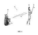
- FIG. 1is an illustration of a golfer using a golf club utilizing a device with a power-saving circuit having a radiofrequency transmission component.
- FIG. 2is a perspective view of a device with a power-saving circuit having a radiofrequency transmission component.
- FIG. 3is an interior view of a device with a power-saving circuit having a radiofrequency transmission component.
- FIG. 4is an illustration of the circuit diagram of a power-saving circuit having a radiofrequency transmission component.
- FIG. 5is a flow chart of a method for shot tracking utilizing a device with a power-saving circuit having a radiofrequency transmission component.
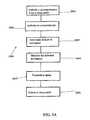
- FIG. 5Ais a flow chart for a preferred method for conserving power in a circuit having a radiofrequency transmission component.
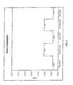
- FIG. 6is a graph of power consumption for a device with a power-saving circuit having a radiofrequency transmission component wherein no motion has been detected.
- FIG. 7is a graph of power consumption for a device with a power-saving circuit having a radiofrequency transmission component wherein motion has been detected.
- FIG. 1A system for shot tracking is illustrated in FIG. 1 .
- a golfer 40strikes a golf ball with a golf club 50 .
- the golf club 50includes a device 20 preferably positioned within a grip.
- the device 20includes a circuit 25 for transmitting a RFID signal while conserving the battery power of the device 20 .
- the RFID signal 62is preferably transmitted to a receiver 60 attached to a golf bag 61 .
- the RFID signalpreferably comprises the golf club 50 used by the golfer and golf swing information.
- the receiver 60is preferably a GPS device such as disclosed in Balardeta et al., U.S. Patent Publication Number 20090075761 for a Golf GPS Device And System, which is hereby incorporated by reference in its entirety.
- the receiveris a personal digital assistant (PDA), “smart phone”, mobile phone, or other similar device.
- PDApersonal digital assistant
- the receivermay be any type of receiver capable of receiving and storing signals from the device 20 .
- FIG. 2illustrates the device 20 including the main body 22 a and a projection 22 b .
- the projection 22 bpreferably is placed within an aperture of a grip (not shown) of a golf club 50 .
- the projection body 22 bpreferably has a length that ranges from 1 millimeter (“mm”) to 5 mm.
- the main body 22 apreferably has a diameter, D, that ranges from 20 mm to 25 mm.
- the interior components of the device 20are illustrated in FIG. 3 .
- the interior componentsare preferably held within a housing 22 of the device 20 .
- the interior componentscomprise a battery 24 , a circuit board 26 having an accelerometer 28 , a gyroscope 29 , a microprocessor 30 a and a RFID component 30 b .
- the housing 22is composed of a rubberized material formed around the battery 24 and the circuit board 26 .
- the housing 22is composed of an epoxy material formed around the battery 24 and the circuit board 26 .
- FIG. 4illustrates a circuit diagram of a preferred embodiment of the present invention.
- a circuit 25includes a battery 24 , an accelerometer 28 , a gyroscope 29 , a microprocessor 30 a and an RFID component 30 b .
- the battery 24is preferably a CR2032 lithium battery having 225 milliamp hours of power. In a device 20 , under continuous operation, the battery 24 should provide power for an estimated five years of normal use of the device 20 .
- the microprocessor 30 ais preferably a MC9S08QG8/4 microprocessor from Freescale Semiconductor.
- the accelerometer 28is preferably a LIS3DH ultra low-power high-performance 3-axes nano accelerometer from ST Microelectronics, which has a 32 first in first out (FIFO) buffer.
- the RFID componentis preferably an RF24L01 single chip 2.4 gigaHertz transceiver from Nordic Semiconductor.
- a method 2000 for conserving power for the circuit 25is set forth in FIG. 5A .
- the microprocessor 30 ais activated from a sleep mode to a sampling mode.
- a preferred time period for the sleep modeis between ten to fifteen seconds.
- the circuit 25preferably consumes less than 600 nano-amps during the sleep mode.
- the time period for the sleep modeis sufficiently long enough to provide power savings for the battery 24 but short enough to capture any activity for the circuit 25 .
- the microprocessor 30 aactivates the accelerometer 28 .
- the circuit 25preferably consumes less than 15 micro-amps during the sampling mode.
- the accelerometer 28is determines if there is any movement or change from the last sampling mode.
- the accelerometer 28determines if there is motion activity during an analysis mode.
- the circuit 25preferably consumes less than 50 micro-amps during the analysis mode.
- the accelerometermonitors the motion activity during a monitoring mode and communicates the motion activity to the microprocessor 30 a . If triggered, the gyroscope 29 is activated by the accelerometer 28 . The gyroscope 29 monitors movement during the monitoring mode and communicates that movement to the microprocessor 30 a .
- the circuit 25preferably consumes less than 200 micro-amps during the monitoring mode.
- the radiofrequency component 30 btransmits a signal during a transmission mode. The signal comprises data related to the motion activity monitored by the accelerometer 28 .
- the radiofrequency component 30 bpreferably operates at 2.4 giga-Hertz and the power for the radiofrequency component 30 b is drawn from the battery 24 .
- the circuit 25preferably consumes less than 12 milli-amps during the transmission mode.
- the circuit 25returns to a sleep mode.
- the gyroscopeoperates at or less than 5 milli-amps.
- FIG. 6illustrates the power consumption of the device 20 when there is no motion detected. In a preferred embodiment, this is when a golf club 50 is in a golf bag and not in use.
- the device 20transitions from a sleep mode to a sampling mode wherein during the sleep mode less than 600 nano-amps are consumed by the device 20 since the only component operating is the microprocessor 30 a , which is operating at a minimal activity.
- the microprocessor 30 abecomes more active and the accelerometer 28 is activated to determine if there is any movement or change from the last sampling mode.
- less than 15 micro-amps of poweris consumed by the device 20 .
- no motionis detected and the device 20 transitions again to the sleep mode.
- FIG. 7illustrates the power consumption of the device 20 when there is motion detected. In a preferred embodiment, this is when a golf club 50 is used to strike a golf ball during a round of golf at a golf course.
- the power consumptionbegins at the sleep mode and transitions to the sampling mode.
- motionis detected by the accelerometer 28 during the sampling mode. The motion is at least more than a zero g reading by the accelerometer 28 .
- the device 20transitions to an analysis mode, which consumes less than less than 50 micro-amps of power.
- the microprocessor 30 a with input from the accelerometer 28determines the type of motion.
- the device 20determines if the golfer is only taking a practice swing, if the golf club 50 has been removed from the golf bag 61 and is no longer in motion, or more importantly if the golfer is about to strike a golf ball. If the device 20 determines that the golfer is about to strike a golf ball, the device 20 transitions to the monitoring mode which consumes less than 200 micro-amps of power. In a preferred embodiment, during the monitoring mode the device 20 monitors the golfer's swing with the accelerometer 28 fully operable.
- the device 20transitions to a transmission mode which consumes less than 12 milli-amps.
- the radiofrequency component 30 btransmits a signal.
- the signalcomprises data related to the motion activity monitored by the accelerometer 28 .
- the microprocessor 30 ais configured to deactivate transmissions of the signal when a threshold number of signals are transmitted by the device 20 and a receipt signal is not received by the device 20 .
- the threshold number of signalspreferably ranges from 5 to 50, more preferably from 15 to 30 and is most preferred to be 20. Each signal transmitted consumes approximately 2 milliamps of power.
- the microprocessor 30 ais in electrical communication with the radiofrequency component 30 b , wherein a signal 62 is transmitted from the radiofrequency component 30 b and a confirmation signal is received at the radiofrequency component 30 b , wherein the radiofrequency component 30 b preferably operates at 2.4 giga-Hertz. A peak current of transmission of the signal is limited to 2 milliamps.
- a method 1000 for shot tracking during a round of golf at a golf courseis illustrated in FIG. 5 and explained in conjunction with FIG. 1 .
- a golf club 50is swung to impact a golf ball during a round of golf.
- at least one signalis transmitted from a RFID component 30 b of a shot tracking device 20 attached to a golf club 50 to indicate that the golf club 50 has been used to strike a golf ball during a round of golf.
- the signalis received at a receiver 60 , which is preferably a GPS device as discussed above.
- the receiver/GPS device 60determines the geographical location of the golfer on the golf course and stores the golf club 50 used at that location.
- the receiver/GPS device 60would record the location as the first hole, the golf club used as a driver, and any other swing performance information provided by the device 20 .
- the device 20transmits a signal to the receiver/GPS device 60 that the golfer struck the golf ball using a subsequent golf club, for example a six iron.
- the receiver/GPS device 60determines the location on the golf course and from that location determines the distance of the previous shot by the golfer. The process continues for the entire round of golf. Once the round is finished, at block 1005 , the receiver/GPS unit 60 uploads the data from the round to a Web site for further processing and display on a personal Web page where the golfer can compare the latest round against previous rounds.
- the golf club 50is any golf club of a set, and preferably every golf club in a golfer's golf bag 61 has a device 20 attached thereto. Further, a resolution of the accelerometer 28 is set to each particular golf club 50 . For example, a putter requires a higher resolution than a driver since the movement of the putter during a golf swing is much less than the movement of a driver during a golf swing. In this manner, the device 20 for a putter has an accelerometer 28 set at a high resolution.
- the circuit 26 for transmitting a RFID signal 62 while conserving battery powercomprises a battery 24 having no more than 225 milliamp hours of power, a microprocessor 30 ( a ) in electrical communication with the battery 24 , the microprocessor 30 ( a ) operating during a sleep mode, a sampling mode, an analysis mode, a monitoring mode and a transmission mode.
- the circuitfurther comprises a multi-axis accelerometer 30 ( e ) for determining movement, monitoring movement and communicating the movement to the microprocessor 30 ( a ).
- the circuitfurther comprising a gyroscope 29 , the gyroscope 29 in electrical communication with the accelerometer 28 , the gyroscope 29 determining movement, monitoring movement and communicating the movement to the microprocessor 30 ( a ).
- the multi-axis accelerometer 30 ( e )is in electrical communication with the microprocessor 30 ( a ).
- the power for the multi-axis accelerometer 30 ( e )is drawn from the battery 24 .
- the multi-axis accelerometer 30 ( e )is only active during the sampling mode, the analysis mode and the monitoring mode.
- the circuitfurther comprises a radiofrequency component 30 ( b ) in electrical communication with the microprocessor 30 ( a ), the radiofrequency component 30 ( b ) operating at 2.4 giga-Hertz.
- the power for the radiofrequency component 30 ( b )is drawn from the battery 24 .
- the radiofrequency component 30 ( b )is only operable during a transmission mode, transmitting a signal 62 from the radiofrequency component 30 ( b ) during the transmission mode.
- the signal 62comprises data related to the movement monitored by the multi-axis accelerometer 30 ( e ).
- the circuitis in continuous operation. The circuit consumes less than 600 nano-amps during the sleep mode, the sleep mode having a time period ranging from 5 seconds to 45 seconds.
- the circuitconsumes less than 15 micro-amps during the sampling mode.
- the circuitconsumes less than 50 micro-amps during the analysis mode.
- the circuitconsumes less than 200 micro-amps during the monitoring mode and the circuit consumes less than 12 milli-amps during the transmission mode.
- the gyroscopeoperates at or less than 5 milli-amps.
- Pat. No. 7,258,626is hereby incorporated by reference in its entirety.
- Galloway, et al., U.S. Pat. No. 7,258,631is hereby incorporated by reference in its entirety.
- Evans, et al., U.S. Pat. No. 7,273,419is hereby incorporated by reference in its entirety.
- Hocknell, et al., U.S. Pat. No. 7,413,520is hereby incorporated by reference in its entirety.
- the measurementsmay be inputted into an impact code such as the rigid body code disclosed in U.S. Pat. No. 6,821,209, entitled Method for Predicting a Golfer's Ball Striking Performance, which is hereby incorporated by reference in its entirety.
- an impact codesuch as the rigid body code disclosed in U.S. Pat. No. 6,821,209, entitled Method for Predicting a Golfer's Ball Striking Performance, which is hereby incorporated by reference in its entirety.
- the swing propertiesare preferably determined using an acquisition system such as disclosed in U.S. Pat. No. 6,431,990, entitled System and Method for Measuring a Golfer's Ball Striking Parameters, assigned to Callaway Golf Company, the assignee of the present application, and hereby incorporated by reference in its entirety.
- acquisition systemsuch as disclosed in U.S. Pat. No. 6,431,990, entitled System and Method for Measuring a Golfer's Ball Striking Parameters, assigned to Callaway Golf Company, the assignee of the present application, and hereby incorporated by reference in its entirety.
- other acquisition systemsmay be used to determine the swing properties.
Landscapes
- Engineering & Computer Science (AREA)
- Computer Hardware Design (AREA)
- Microelectronics & Electronic Packaging (AREA)
- Physics & Mathematics (AREA)
- General Physics & Mathematics (AREA)
- Theoretical Computer Science (AREA)
- Computer Networks & Wireless Communication (AREA)
- Gyroscopes (AREA)
Abstract
Description
Claims (19)
Priority Applications (1)
| Application Number | Priority Date | Filing Date | Title |
|---|---|---|---|
| US12/950,540US8446255B2 (en) | 2010-11-19 | 2010-11-19 | Circuit for transmitting a RFID signal |
Applications Claiming Priority (1)
| Application Number | Priority Date | Filing Date | Title |
|---|---|---|---|
| US12/950,540US8446255B2 (en) | 2010-11-19 | 2010-11-19 | Circuit for transmitting a RFID signal |
Publications (2)
| Publication Number | Publication Date |
|---|---|
| US20120126946A1 US20120126946A1 (en) | 2012-05-24 |
| US8446255B2true US8446255B2 (en) | 2013-05-21 |
Family
ID=46063821
Family Applications (1)
| Application Number | Title | Priority Date | Filing Date |
|---|---|---|---|
| US12/950,540Active2032-02-14US8446255B2 (en) | 2010-11-19 | 2010-11-19 | Circuit for transmitting a RFID signal |
Country Status (1)
| Country | Link |
|---|---|
| US (1) | US8446255B2 (en) |
Cited By (9)
| Publication number | Priority date | Publication date | Assignee | Title |
|---|---|---|---|---|
| US9339714B2 (en) | 2014-05-20 | 2016-05-17 | Arccos Golf Llc | System and method for monitoring performance characteristics associated with user activities involving swinging instruments |
| US9770639B2 (en) | 2015-07-21 | 2017-09-26 | Arccos Golf, Llc | System and method for monitoring performance characteristics associated with user activities involving swinging instruments |
| US10232225B1 (en) | 2015-06-01 | 2019-03-19 | Mitchell O Enterprises LLC | Systems and methods for obtaining sports-related data |
| US10682562B2 (en) | 2017-01-17 | 2020-06-16 | Arccos Golf Llc | Autonomous personalized golf recommendation and analysis environment |
| US10716971B1 (en) | 2015-06-01 | 2020-07-21 | Mitchell O Enterprises LLC | Game implements and system for tracking or locating same |
| US10918929B1 (en)* | 2018-07-13 | 2021-02-16 | Callaway Golf Company | Golf ball with electrical components |
| US11344784B1 (en)* | 2018-07-13 | 2022-05-31 | Callaway Golf Company | Golf ball with wound core with integrated circuit |
| US11786794B1 (en)* | 2018-07-13 | 2023-10-17 | Topgolf Callaway Brands Corp. | Golf club head impact location based on 3D magnetic field readings |
| US12172066B2 (en) | 2017-01-17 | 2024-12-24 | Arccos Golf Llc | Autonomous tracking and personalized golf recommendation and analysis environment |
Families Citing this family (4)
| Publication number | Priority date | Publication date | Assignee | Title |
|---|---|---|---|---|
| US9821210B2 (en)* | 2011-05-11 | 2017-11-21 | Karsten Manufacturing Corporation | Systems, methods, and articles of manufacture to measure, analyze and share golf swing characteristics |
| JPWO2013190722A1 (en)* | 2012-06-20 | 2016-02-08 | 株式会社ニコン | Electronics |
| US9576234B2 (en)* | 2013-12-03 | 2017-02-21 | Trapeze Software Ulc | Method and system for power management of asset tracking system for non-stationary assets |
| US10463944B2 (en)* | 2013-12-24 | 2019-11-05 | Sony Corporation | Sensor device and recording medium |
Citations (15)
| Publication number | Priority date | Publication date | Assignee | Title |
|---|---|---|---|---|
| US6224493B1 (en) | 1999-05-12 | 2001-05-01 | Callaway Golf Company | Instrumented golf club system and method of use |
| US6431990B1 (en) | 2001-01-19 | 2002-08-13 | Callaway Golf Company | System and method for measuring a golfer's ball striking parameters |
| US20020174153A1 (en)* | 1996-05-13 | 2002-11-21 | O'toole James E. | Radio frequency data communications device |
| US6638175B2 (en) | 1999-05-12 | 2003-10-28 | Callaway Golf Company | Diagnostic golf club system |
| US6821209B2 (en) | 2001-12-21 | 2004-11-23 | Callaway Golf Company | Method for predicting a golfer's ball striking performance |
| US7163468B2 (en) | 2005-01-03 | 2007-01-16 | Callaway Golf Company | Golf club head |
| US7163470B2 (en) | 2004-06-25 | 2007-01-16 | Callaway Golf Company | Golf club head |
| US7166038B2 (en) | 2005-01-03 | 2007-01-23 | Callaway Golf Company | Golf club head |
| US7214143B2 (en) | 2005-03-18 | 2007-05-08 | Callaway Golf Company | Golf club head with a face insert |
| US7252600B2 (en) | 1999-11-01 | 2007-08-07 | Callaway Golf Company | Multiple material golf club head |
| US7258626B2 (en) | 2004-10-07 | 2007-08-21 | Callaway Golf Company | Golf club head with variable face thickness |
| US7273419B2 (en) | 2004-09-10 | 2007-09-25 | Callaway Golf Company | Multiple material golf club head |
| US7413520B1 (en) | 2007-03-09 | 2008-08-19 | Callaway Golf Company | Golf club head with high moment of inertia |
| US20090075761A1 (en) | 2007-09-18 | 2009-03-19 | Joseph Balardeta | Golf gps device and system |
| US20090318779A1 (en)* | 2006-05-24 | 2009-12-24 | Bao Tran | Mesh network stroke monitoring appliance |
- 2010
- 2010-11-19USUS12/950,540patent/US8446255B2/enactiveActive
Patent Citations (17)
| Publication number | Priority date | Publication date | Assignee | Title |
|---|---|---|---|---|
| US20020174153A1 (en)* | 1996-05-13 | 2002-11-21 | O'toole James E. | Radio frequency data communications device |
| US6402634B2 (en) | 1999-05-12 | 2002-06-11 | Callaway Golf Company | Instrumented golf club system and method of use |
| US6638175B2 (en) | 1999-05-12 | 2003-10-28 | Callaway Golf Company | Diagnostic golf club system |
| US6224493B1 (en) | 1999-05-12 | 2001-05-01 | Callaway Golf Company | Instrumented golf club system and method of use |
| US7252600B2 (en) | 1999-11-01 | 2007-08-07 | Callaway Golf Company | Multiple material golf club head |
| US6431990B1 (en) | 2001-01-19 | 2002-08-13 | Callaway Golf Company | System and method for measuring a golfer's ball striking parameters |
| US6821209B2 (en) | 2001-12-21 | 2004-11-23 | Callaway Golf Company | Method for predicting a golfer's ball striking performance |
| US7163470B2 (en) | 2004-06-25 | 2007-01-16 | Callaway Golf Company | Golf club head |
| US7258631B2 (en) | 2004-06-25 | 2007-08-21 | Callaway Golf Company | Golf club head |
| US7273419B2 (en) | 2004-09-10 | 2007-09-25 | Callaway Golf Company | Multiple material golf club head |
| US7258626B2 (en) | 2004-10-07 | 2007-08-21 | Callaway Golf Company | Golf club head with variable face thickness |
| US7166038B2 (en) | 2005-01-03 | 2007-01-23 | Callaway Golf Company | Golf club head |
| US7163468B2 (en) | 2005-01-03 | 2007-01-16 | Callaway Golf Company | Golf club head |
| US7214143B2 (en) | 2005-03-18 | 2007-05-08 | Callaway Golf Company | Golf club head with a face insert |
| US20090318779A1 (en)* | 2006-05-24 | 2009-12-24 | Bao Tran | Mesh network stroke monitoring appliance |
| US7413520B1 (en) | 2007-03-09 | 2008-08-19 | Callaway Golf Company | Golf club head with high moment of inertia |
| US20090075761A1 (en) | 2007-09-18 | 2009-03-19 | Joseph Balardeta | Golf gps device and system |
Cited By (15)
| Publication number | Priority date | Publication date | Assignee | Title |
|---|---|---|---|---|
| US10427017B2 (en) | 2014-05-20 | 2019-10-01 | Arccos Golf Llc | System and method for monitoring performance characteristics associated with user activities involving swinging instruments |
| US9339714B2 (en) | 2014-05-20 | 2016-05-17 | Arccos Golf Llc | System and method for monitoring performance characteristics associated with user activities involving swinging instruments |
| US10716971B1 (en) | 2015-06-01 | 2020-07-21 | Mitchell O Enterprises LLC | Game implements and system for tracking or locating same |
| US10232225B1 (en) | 2015-06-01 | 2019-03-19 | Mitchell O Enterprises LLC | Systems and methods for obtaining sports-related data |
| US10589161B2 (en) | 2015-07-21 | 2020-03-17 | Arccos Golf, Llc | System and method for monitoring performance characteristics associated with user activities involving swinging instruments |
| US9770639B2 (en) | 2015-07-21 | 2017-09-26 | Arccos Golf, Llc | System and method for monitoring performance characteristics associated with user activities involving swinging instruments |
| US10682562B2 (en) | 2017-01-17 | 2020-06-16 | Arccos Golf Llc | Autonomous personalized golf recommendation and analysis environment |
| US11219814B2 (en) | 2017-01-17 | 2022-01-11 | Arccos Golf Llc | Autonomous personalized golf recommendation and analysis environment |
| US12172066B2 (en) | 2017-01-17 | 2024-12-24 | Arccos Golf Llc | Autonomous tracking and personalized golf recommendation and analysis environment |
| US10918929B1 (en)* | 2018-07-13 | 2021-02-16 | Callaway Golf Company | Golf ball with electrical components |
| US11344784B1 (en)* | 2018-07-13 | 2022-05-31 | Callaway Golf Company | Golf ball with wound core with integrated circuit |
| US11344785B1 (en)* | 2018-07-13 | 2022-05-31 | Callaway Golf Company | Golf ball with electrical components |
| US11786794B1 (en)* | 2018-07-13 | 2023-10-17 | Topgolf Callaway Brands Corp. | Golf club head impact location based on 3D magnetic field readings |
| US11872461B1 (en)* | 2018-07-13 | 2024-01-16 | Topgolf Callaway Brands Corp. | Golf ball with wound core with integrated circuit |
| US12280305B1 (en)* | 2018-07-13 | 2025-04-22 | Topgolf Callaway Brands Corp. | Golf club head impact location based on 3D magnetic field readings |
Also Published As
| Publication number | Publication date |
|---|---|
| US20120126946A1 (en) | 2012-05-24 |
Similar Documents
| Publication | Publication Date | Title |
|---|---|---|
| US7800480B1 (en) | Method and system for shot tracking | |
| US7831212B1 (en) | Circuit for transmitting a RFID signal | |
| US8446255B2 (en) | Circuit for transmitting a RFID signal | |
| US8272970B2 (en) | Device for shot tracking | |
| US7804404B1 (en) | Circuit for transmitting a RFID signal | |
| US9289670B2 (en) | Method and system for power conservation of a RF device during shipping | |
| US7979030B1 (en) | Circuit for transmitting a RFID signal | |
| US8845459B2 (en) | Method and system for shot tracking | |
| US8192293B2 (en) | Method and system for shot tracking | |
| US7801575B1 (en) | Method and system for shot tracking | |
| US8444499B2 (en) | Method and system for shot tracking | |
| US8992346B1 (en) | Method and system for swing analysis | |
| US8120332B2 (en) | Method and system for shot tracking | |
| US7883427B1 (en) | Device for shot tracking | |
| US20120015754A1 (en) | Method and sysem for shot tracking | |
| US20110151986A1 (en) | Method and system for shot tracking | |
| US12290732B1 (en) | System and method to identify impact locations | |
| CN113286639A (en) | Electronic tag for golf ball hitting detection | |
| US8430762B2 (en) | Method and system for shot tracking | |
| US7911186B1 (en) | Method and system for shot tracking | |
| CN103542843A (en) | Apparatus and system for measuring swinging velocity of racket | |
| US20110143849A1 (en) | Method and system for shot tracking | |
| US20120015753A1 (en) | Method and system for shot tracking | |
| CN202710070U (en) | Device and system for measuring racket swinging speed | |
| HK40051573A (en) | Electronic tag for golf shot detection |
Legal Events
| Date | Code | Title | Description |
|---|---|---|---|
| AS | Assignment | Owner name:CALLAWAY GOLF COMPANY, CALIFORNIA Free format text:ASSIGNMENT OF ASSIGNORS INTEREST;ASSIGNORS:BALARDETA, JOSEPH;DENTON, SCOTT;REEL/FRAME:025389/0211 Effective date:20101119 | |
| STCF | Information on status: patent grant | Free format text:PATENTED CASE | |
| FPAY | Fee payment | Year of fee payment:4 | |
| AS | Assignment | Owner name:BANK OF AMERICA, N.A., CALIFORNIA Free format text:SECURITY INTEREST;ASSIGNORS:CALLAWAY GOLF COMPANY;CALLAWAY GOLF SALES COMPANY;CALLAWAY GOLF BALL OPERATIONS, INC.;AND OTHERS;REEL/FRAME:045350/0741 Effective date:20171120 | |
| AS | Assignment | Owner name:BANK OF AMERICA, N.A., AS ADMINISTRATIVE AGENT, NO Free format text:SECURITY AGREEMENT;ASSIGNORS:CALLAWAY GOLF COMPANY;OGIO INTERNATIONAL, INC.;REEL/FRAME:048172/0001 Effective date:20190104 Owner name:BANK OF AMERICA, N.A., AS ADMINISTRATIVE AGENT, NORTH CAROLINA Free format text:SECURITY AGREEMENT;ASSIGNORS:CALLAWAY GOLF COMPANY;OGIO INTERNATIONAL, INC.;REEL/FRAME:048172/0001 Effective date:20190104 | |
| AS | Assignment | Owner name:BANK OF AMERICA, N.A., CALIFORNIA Free format text:SECURITY INTEREST;ASSIGNORS:CALLAWAY GOLF COMPANY;CALLAWAY GOLF SALES COMPANY;CALLAWAY GOLF BALL OPERATIONS, INC.;AND OTHERS;REEL/FRAME:048110/0352 Effective date:20190104 | |
| MAFP | Maintenance fee payment | Free format text:PAYMENT OF MAINTENANCE FEE, 8TH YEAR, LARGE ENTITY (ORIGINAL EVENT CODE: M1552); ENTITY STATUS OF PATENT OWNER: LARGE ENTITY Year of fee payment:8 | |
| AS | Assignment | Owner name:OGIO INTERNATIONAL, INC., CALIFORNIA Free format text:RELEASE (REEL 048172 / FRAME 0001);ASSIGNOR:BANK OF AMERICA, N.A.;REEL/FRAME:063622/0187 Effective date:20230316 Owner name:TOPGOLF CALLAWAY BRANDS CORP. (F/K/A CALLAWAY GOLF COMPANY), CALIFORNIA Free format text:RELEASE (REEL 048172 / FRAME 0001);ASSIGNOR:BANK OF AMERICA, N.A.;REEL/FRAME:063622/0187 Effective date:20230316 | |
| AS | Assignment | Owner name:BANK OF AMERICA, N.A, AS COLLATERAL AGENT, NORTH CAROLINA Free format text:SECURITY AGREEMENT;ASSIGNORS:TOPGOLF CALLAWAY BRANDS CORP. (FORMERLY CALLAWAY GOLF COMPANY);OGIO INTERNATIONAL, INC.;TOPGOLF INTERNATIONAL, INC.;AND OTHERS;REEL/FRAME:063665/0176 Effective date:20230512 | |
| AS | Assignment | Owner name:BANK OF AMERICA, N.A., CALIFORNIA Free format text:SECURITY INTEREST;ASSIGNORS:TOPGOLF CALLAWAY BRANDS CORP.;OGIO INTERNATIONAL, INC.;TOPGOLF INTERNATIONAL, INC.;AND OTHERS;REEL/FRAME:063692/0009 Effective date:20230517 | |
| MAFP | Maintenance fee payment | Free format text:PAYMENT OF MAINTENANCE FEE, 12TH YEAR, LARGE ENTITY (ORIGINAL EVENT CODE: M1553); ENTITY STATUS OF PATENT OWNER: LARGE ENTITY Year of fee payment:12 |