US8444646B2 - Bone preparation tool kit and associated method - Google Patents
Bone preparation tool kit and associated methodDownload PDFInfo
- Publication number
- US8444646B2 US8444646B2US12/421,335US42133509AUS8444646B2US 8444646 B2US8444646 B2US 8444646B2US 42133509 AUS42133509 AUS 42133509AUS 8444646 B2US8444646 B2US 8444646B2
- Authority
- US
- United States
- Prior art keywords
- prosthesis
- humerus
- tool
- reamer
- tool kit
- Prior art date
- Legal status (The legal status is an assumption and is not a legal conclusion. Google has not performed a legal analysis and makes no representation as to the accuracy of the status listed.)
- Expired - Lifetime, expires
Links
Images


Classifications
- A—HUMAN NECESSITIES
- A61—MEDICAL OR VETERINARY SCIENCE; HYGIENE
- A61F—FILTERS IMPLANTABLE INTO BLOOD VESSELS; PROSTHESES; DEVICES PROVIDING PATENCY TO, OR PREVENTING COLLAPSING OF, TUBULAR STRUCTURES OF THE BODY, e.g. STENTS; ORTHOPAEDIC, NURSING OR CONTRACEPTIVE DEVICES; FOMENTATION; TREATMENT OR PROTECTION OF EYES OR EARS; BANDAGES, DRESSINGS OR ABSORBENT PADS; FIRST-AID KITS
- A61F2/00—Filters implantable into blood vessels; Prostheses, i.e. artificial substitutes or replacements for parts of the body; Appliances for connecting them with the body; Devices providing patency to, or preventing collapsing of, tubular structures of the body, e.g. stents
- A61F2/02—Prostheses implantable into the body
- A61F2/30—Joints
- A61F2/40—Joints for shoulders
- A61F2/4003—Replacing only the epiphyseal or metaphyseal parts of the humerus, i.e. endoprosthesis not comprising an entire humeral shaft
- A—HUMAN NECESSITIES
- A61—MEDICAL OR VETERINARY SCIENCE; HYGIENE
- A61B—DIAGNOSIS; SURGERY; IDENTIFICATION
- A61B17/00—Surgical instruments, devices or methods
- A61B17/14—Surgical saws
- A—HUMAN NECESSITIES
- A61—MEDICAL OR VETERINARY SCIENCE; HYGIENE
- A61B—DIAGNOSIS; SURGERY; IDENTIFICATION
- A61B17/00—Surgical instruments, devices or methods
- A61B17/14—Surgical saws
- A61B17/15—Guides therefor
- A—HUMAN NECESSITIES
- A61—MEDICAL OR VETERINARY SCIENCE; HYGIENE
- A61B—DIAGNOSIS; SURGERY; IDENTIFICATION
- A61B17/00—Surgical instruments, devices or methods
- A61B17/16—Instruments for performing osteoclasis; Drills or chisels for bones; Trepans
- A61B17/1642—Instruments for performing osteoclasis; Drills or chisels for bones; Trepans for producing a curved bore
- A—HUMAN NECESSITIES
- A61—MEDICAL OR VETERINARY SCIENCE; HYGIENE
- A61B—DIAGNOSIS; SURGERY; IDENTIFICATION
- A61B17/00—Surgical instruments, devices or methods
- A61B17/16—Instruments for performing osteoclasis; Drills or chisels for bones; Trepans
- A61B17/1662—Instruments for performing osteoclasis; Drills or chisels for bones; Trepans for particular parts of the body
- A61B17/1684—Instruments for performing osteoclasis; Drills or chisels for bones; Trepans for particular parts of the body for the shoulder
- A—HUMAN NECESSITIES
- A61—MEDICAL OR VETERINARY SCIENCE; HYGIENE
- A61B—DIAGNOSIS; SURGERY; IDENTIFICATION
- A61B17/00—Surgical instruments, devices or methods
- A61B17/16—Instruments for performing osteoclasis; Drills or chisels for bones; Trepans
- A61B17/17—Guides or aligning means for drills, mills, pins or wires
- A61B17/1739—Guides or aligning means for drills, mills, pins or wires specially adapted for particular parts of the body
- A61B17/1778—Guides or aligning means for drills, mills, pins or wires specially adapted for particular parts of the body for the shoulder
- A—HUMAN NECESSITIES
- A61—MEDICAL OR VETERINARY SCIENCE; HYGIENE
- A61F—FILTERS IMPLANTABLE INTO BLOOD VESSELS; PROSTHESES; DEVICES PROVIDING PATENCY TO, OR PREVENTING COLLAPSING OF, TUBULAR STRUCTURES OF THE BODY, e.g. STENTS; ORTHOPAEDIC, NURSING OR CONTRACEPTIVE DEVICES; FOMENTATION; TREATMENT OR PROTECTION OF EYES OR EARS; BANDAGES, DRESSINGS OR ABSORBENT PADS; FIRST-AID KITS
- A61F2/00—Filters implantable into blood vessels; Prostheses, i.e. artificial substitutes or replacements for parts of the body; Appliances for connecting them with the body; Devices providing patency to, or preventing collapsing of, tubular structures of the body, e.g. stents
- A61F2/02—Prostheses implantable into the body
- A61F2/30—Joints
- A61F2/40—Joints for shoulders
- A61F2/4059—Humeral shafts
- A—HUMAN NECESSITIES
- A61—MEDICAL OR VETERINARY SCIENCE; HYGIENE
- A61F—FILTERS IMPLANTABLE INTO BLOOD VESSELS; PROSTHESES; DEVICES PROVIDING PATENCY TO, OR PREVENTING COLLAPSING OF, TUBULAR STRUCTURES OF THE BODY, e.g. STENTS; ORTHOPAEDIC, NURSING OR CONTRACEPTIVE DEVICES; FOMENTATION; TREATMENT OR PROTECTION OF EYES OR EARS; BANDAGES, DRESSINGS OR ABSORBENT PADS; FIRST-AID KITS
- A61F2/00—Filters implantable into blood vessels; Prostheses, i.e. artificial substitutes or replacements for parts of the body; Appliances for connecting them with the body; Devices providing patency to, or preventing collapsing of, tubular structures of the body, e.g. stents
- A61F2/02—Prostheses implantable into the body
- A61F2/30—Joints
- A61F2/46—Special tools for implanting artificial joints
- A61F2/4603—Special tools for implanting artificial joints for insertion or extraction of endoprosthetic joints or of accessories thereof
- A61F2/4612—Special tools for implanting artificial joints for insertion or extraction of endoprosthetic joints or of accessories thereof of shoulders
- A—HUMAN NECESSITIES
- A61—MEDICAL OR VETERINARY SCIENCE; HYGIENE
- A61B—DIAGNOSIS; SURGERY; IDENTIFICATION
- A61B17/00—Surgical instruments, devices or methods
- A61B17/16—Instruments for performing osteoclasis; Drills or chisels for bones; Trepans
- A61B2017/1602—Mills
- A—HUMAN NECESSITIES
- A61—MEDICAL OR VETERINARY SCIENCE; HYGIENE
- A61F—FILTERS IMPLANTABLE INTO BLOOD VESSELS; PROSTHESES; DEVICES PROVIDING PATENCY TO, OR PREVENTING COLLAPSING OF, TUBULAR STRUCTURES OF THE BODY, e.g. STENTS; ORTHOPAEDIC, NURSING OR CONTRACEPTIVE DEVICES; FOMENTATION; TREATMENT OR PROTECTION OF EYES OR EARS; BANDAGES, DRESSINGS OR ABSORBENT PADS; FIRST-AID KITS
- A61F2/00—Filters implantable into blood vessels; Prostheses, i.e. artificial substitutes or replacements for parts of the body; Appliances for connecting them with the body; Devices providing patency to, or preventing collapsing of, tubular structures of the body, e.g. stents
- A61F2/02—Prostheses implantable into the body
- A61F2/30—Joints
- A61F2002/30001—Additional features of subject-matter classified in A61F2/28, A61F2/30 and subgroups thereof
- A61F2002/30108—Shapes
- A61F2002/30199—Three-dimensional shapes
- A61F2002/30242—Three-dimensional shapes spherical
- A61F2002/30245—Partial spheres
- A—HUMAN NECESSITIES
- A61—MEDICAL OR VETERINARY SCIENCE; HYGIENE
- A61F—FILTERS IMPLANTABLE INTO BLOOD VESSELS; PROSTHESES; DEVICES PROVIDING PATENCY TO, OR PREVENTING COLLAPSING OF, TUBULAR STRUCTURES OF THE BODY, e.g. STENTS; ORTHOPAEDIC, NURSING OR CONTRACEPTIVE DEVICES; FOMENTATION; TREATMENT OR PROTECTION OF EYES OR EARS; BANDAGES, DRESSINGS OR ABSORBENT PADS; FIRST-AID KITS
- A61F2/00—Filters implantable into blood vessels; Prostheses, i.e. artificial substitutes or replacements for parts of the body; Appliances for connecting them with the body; Devices providing patency to, or preventing collapsing of, tubular structures of the body, e.g. stents
- A61F2/02—Prostheses implantable into the body
- A61F2/30—Joints
- A61F2002/30001—Additional features of subject-matter classified in A61F2/28, A61F2/30 and subgroups thereof
- A61F2002/30108—Shapes
- A61F2002/30199—Three-dimensional shapes
- A61F2002/30299—Three-dimensional shapes umbrella-shaped or mushroom-shaped
- A—HUMAN NECESSITIES
- A61—MEDICAL OR VETERINARY SCIENCE; HYGIENE
- A61F—FILTERS IMPLANTABLE INTO BLOOD VESSELS; PROSTHESES; DEVICES PROVIDING PATENCY TO, OR PREVENTING COLLAPSING OF, TUBULAR STRUCTURES OF THE BODY, e.g. STENTS; ORTHOPAEDIC, NURSING OR CONTRACEPTIVE DEVICES; FOMENTATION; TREATMENT OR PROTECTION OF EYES OR EARS; BANDAGES, DRESSINGS OR ABSORBENT PADS; FIRST-AID KITS
- A61F2/00—Filters implantable into blood vessels; Prostheses, i.e. artificial substitutes or replacements for parts of the body; Appliances for connecting them with the body; Devices providing patency to, or preventing collapsing of, tubular structures of the body, e.g. stents
- A61F2/02—Prostheses implantable into the body
- A61F2/30—Joints
- A61F2002/30001—Additional features of subject-matter classified in A61F2/28, A61F2/30 and subgroups thereof
- A61F2002/30621—Features concerning the anatomical functioning or articulation of the prosthetic joint
- A61F2002/30649—Ball-and-socket joints
- A61F2002/3065—Details of the ball-shaped head
- A—HUMAN NECESSITIES
- A61—MEDICAL OR VETERINARY SCIENCE; HYGIENE
- A61F—FILTERS IMPLANTABLE INTO BLOOD VESSELS; PROSTHESES; DEVICES PROVIDING PATENCY TO, OR PREVENTING COLLAPSING OF, TUBULAR STRUCTURES OF THE BODY, e.g. STENTS; ORTHOPAEDIC, NURSING OR CONTRACEPTIVE DEVICES; FOMENTATION; TREATMENT OR PROTECTION OF EYES OR EARS; BANDAGES, DRESSINGS OR ABSORBENT PADS; FIRST-AID KITS
- A61F2/00—Filters implantable into blood vessels; Prostheses, i.e. artificial substitutes or replacements for parts of the body; Appliances for connecting them with the body; Devices providing patency to, or preventing collapsing of, tubular structures of the body, e.g. stents
- A61F2/02—Prostheses implantable into the body
- A61F2/30—Joints
- A61F2/30767—Special external or bone-contacting surface, e.g. coating for improving bone ingrowth
- A61F2002/30769—Special external or bone-contacting surface, e.g. coating for improving bone ingrowth madreporic
- A—HUMAN NECESSITIES
- A61—MEDICAL OR VETERINARY SCIENCE; HYGIENE
- A61F—FILTERS IMPLANTABLE INTO BLOOD VESSELS; PROSTHESES; DEVICES PROVIDING PATENCY TO, OR PREVENTING COLLAPSING OF, TUBULAR STRUCTURES OF THE BODY, e.g. STENTS; ORTHOPAEDIC, NURSING OR CONTRACEPTIVE DEVICES; FOMENTATION; TREATMENT OR PROTECTION OF EYES OR EARS; BANDAGES, DRESSINGS OR ABSORBENT PADS; FIRST-AID KITS
- A61F2/00—Filters implantable into blood vessels; Prostheses, i.e. artificial substitutes or replacements for parts of the body; Appliances for connecting them with the body; Devices providing patency to, or preventing collapsing of, tubular structures of the body, e.g. stents
- A61F2/02—Prostheses implantable into the body
- A61F2/30—Joints
- A61F2/40—Joints for shoulders
- A61F2/4003—Replacing only the epiphyseal or metaphyseal parts of the humerus, i.e. endoprosthesis not comprising an entire humeral shaft
- A61F2002/4007—Replacing only the epiphyseal or metaphyseal parts of the humerus, i.e. endoprosthesis not comprising an entire humeral shaft implanted without ablation of the whole natural humeral head
- A—HUMAN NECESSITIES
- A61—MEDICAL OR VETERINARY SCIENCE; HYGIENE
- A61F—FILTERS IMPLANTABLE INTO BLOOD VESSELS; PROSTHESES; DEVICES PROVIDING PATENCY TO, OR PREVENTING COLLAPSING OF, TUBULAR STRUCTURES OF THE BODY, e.g. STENTS; ORTHOPAEDIC, NURSING OR CONTRACEPTIVE DEVICES; FOMENTATION; TREATMENT OR PROTECTION OF EYES OR EARS; BANDAGES, DRESSINGS OR ABSORBENT PADS; FIRST-AID KITS
- A61F2230/00—Geometry of prostheses classified in groups A61F2/00 - A61F2/26 or A61F2/82 or A61F9/00 or A61F11/00 or subgroups thereof
- A61F2230/0063—Three-dimensional shapes
- A61F2230/0093—Umbrella-shaped, e.g. mushroom-shaped
- A—HUMAN NECESSITIES
- A61—MEDICAL OR VETERINARY SCIENCE; HYGIENE
- A61F—FILTERS IMPLANTABLE INTO BLOOD VESSELS; PROSTHESES; DEVICES PROVIDING PATENCY TO, OR PREVENTING COLLAPSING OF, TUBULAR STRUCTURES OF THE BODY, e.g. STENTS; ORTHOPAEDIC, NURSING OR CONTRACEPTIVE DEVICES; FOMENTATION; TREATMENT OR PROTECTION OF EYES OR EARS; BANDAGES, DRESSINGS OR ABSORBENT PADS; FIRST-AID KITS
- A61F2310/00—Prostheses classified in A61F2/28 or A61F2/30 - A61F2/44 being constructed from or coated with a particular material
- A61F2310/00005—The prosthesis being constructed from a particular material
- A61F2310/00011—Metals or alloys
- A—HUMAN NECESSITIES
- A61—MEDICAL OR VETERINARY SCIENCE; HYGIENE
- A61F—FILTERS IMPLANTABLE INTO BLOOD VESSELS; PROSTHESES; DEVICES PROVIDING PATENCY TO, OR PREVENTING COLLAPSING OF, TUBULAR STRUCTURES OF THE BODY, e.g. STENTS; ORTHOPAEDIC, NURSING OR CONTRACEPTIVE DEVICES; FOMENTATION; TREATMENT OR PROTECTION OF EYES OR EARS; BANDAGES, DRESSINGS OR ABSORBENT PADS; FIRST-AID KITS
- A61F2310/00—Prostheses classified in A61F2/28 or A61F2/30 - A61F2/44 being constructed from or coated with a particular material
- A61F2310/00005—The prosthesis being constructed from a particular material
- A61F2310/00179—Ceramics or ceramic-like structures
Definitions
- the present inventionrelates generally to the field of orthopaedics, and more particularly, to an implant for use in arthroplasty.
- the inventionrelates to implantable articles and methods for implanting such articles. More particularly, the invention relates to a bone prosthesis and a method for implanting the same.
- bone prosthesesinclude components of artificial joints, such as elbows, hips, knees and shoulders.
- implantable bone prostheseshave been designed such that they encourage the growth of hard bone tissue around the implant.
- Such implantsare often implanted without cement and the bone grows around surface irregularities, for example, porous structures on the implant.
- One such implantable prosthesisis a shoulder prosthesis.
- a shoulder prosthesisDuring the lifetime of a patient it may be necessary to perform a total shoulder replacement procedure on a patient as a result of, for example, disease or trauma, for example, disease from osteoarthritis or rheumatoid arthritis.
- Most implantable shoulder prosthesesare total shoulder prostheses.
- a humeral component having a head portionis utilized to replace the natural head portion of the upper arm bone or humerus.
- the humeral componenttypically has an elongated intramedullary stem, which is utilized to secure the humeral component to the patient's humerus.
- the natural glenoid surface of the scapulais resurfaced or otherwise replaced with a glenoid component that provides a bearing surface for the head portion of the humeral component.
- the need for a shoulder replacement proceduremay be created by the presence of one of a number of conditions.
- One such conditionis the deterioration of the patient's rotator cuff.
- an intact rotator cuffstabilizes the humeral head in the glenoid fossa of a scapula during abduction of the arm. While it is stabilized in such a manner abduction of the arm causes the humeral head to translate only a short distance in the superior direction (e.g. a few millimeters), whereby a space is maintained between the humeral head and the acromion.
- a short distance in the superior directione.g. a few millimeters
- the humerus 1includes a healthy humeral head 2 .
- the diseased humerus 3includes a diseased or flattened humeral head 4 .
- the healthy humeral head 2 of the healthy humerus 1 of FIG. 2has a generally hemispherical shape
- the flattened humeral head 4is quite flat and only slightly domed.
- FIGS. 4 , 5 and 6a prior art prosthesis 5 is shown.
- the prosthesis 5is shown installed on the diseased humerus 3 .
- the prosthesis 5is positioned over flattened head or bony defect 4 .
- the prosthesis 5includes a hollow generally hemispherical cup 6 . Extending distally from the interior of the cup 6 is a generally conically shaped stem 15 that anchors the prosthesis 5 into the humerus 3 .
- the prosthesis 5is shown implanted in a shoulder joint.
- the humerus 3is shown in a position in which the arm is resting against the patient's torso. Articulating surface of the cup 6 of the prosthesis 5 is shown in contact with the scapula 7 , the clavicle 8 , and the acromion 9 .
- the prosthesis 5provides the articulating surface of cup 6 in contact with the acromion 9 , the clavicle 8 , and the scapula 7 to provide for a acceptable artificial joint in this position.
- the humerus 3is shown abducted in the direction of arrow 10 such that the long bone or humeral centerline 11 is at an angle ⁇ of about fifteen (15) degrees with the vertical centerline 12 .
- the acromion 9is positioned outside the articulating surface 6 of the prosthesis 5 causing the acromion 9 to impinge upon the humerus 3 causing great pain to the patient and severely limited motion of the humerus 3 .
- bipolar prostheseshave also been utilized in an attempt to address the problems associated with cuff tear arthropathy. It was believed that the relatively unstrained motion of the bipolar head would improve shoulder motion.
- heretofore designed bipolar prosthetic headsinclude relatively large offsets, thereby overstuffing the shoulder joint in a similar manner as described above.
- scar tissuemay form around the bipolar head thereby (freezing) the dual articulating motion of the prosthesis that has been known to create a large hemi arthroplasty that likewise overstuffs the shoulder joint.
- bipolar prosthetic headsdo not cover the articulating surface between the greater tubercle and the acromion, thereby creating painful bone-to-bone contact between them.
- What is particularly-neededis a method and apparatus for performing a bone sparing implant shoulder procedure that eliminates painful articulation between the great tubercle of the humerus and the acromion.
- the present inventionprovides for an extended articulation resurfacing shoulder that provides a low-friction prosthetic bearing surface for articulation between the greater tuberosity and the acromion.
- a prosthesisis utilized with a bone sparing minimal resection of a portion of the humeral head.
- the present inventionprovides for an extended articulation resurfacing shoulder with superior/lateral flange for extended articulation into the coracoacromial arch.
- a prosthesis for use in performing joint arthroplastyis provided.
- the prosthesisis to be fitted to a long bone.
- the prosthesisincludes a first body having a first body articulating surface defining a generally circular outer periphery of the first body articulating surface.
- the first bodyhas a support surface opposed to first body articulating surface.
- the support surfaceis adapted to receive the head of the long bone.
- the prosthesisalso includes a second body operably associated with the first body.
- the second bodyhas a second body articulating surface extending from a portion of the circular outer periphery of the first body articulating surface.
- a tool kit for preparing a humerus to receive a prosthesishas a first body having a first articulating surface and an opposed first support surface and has a second body having a second articulating surface and an opposed second support surface.
- the kitis used to prepare the humerus to receive the prosthesis.
- the tool kitincludes a reamer for preparing a first prepared surface on the humerus. The first prepared surface receives the first support surface.
- the tool kitalso includes a bone cutting tool for preparing a second prepared surface on the humerus. The second prepared surface receives the second support surface.
- a method for performing shoulder arthroplasty for an indication of rotator cuff tear arthropathyincludes the step of providing a prosthesis with a first body having a first articulating surface and an opposed first support surface and with a second body having a second articulating surface and an opposed second support surface.
- the methodalso includes the step of providing a tool kit for preparing a humerus for receiving the prosthesis.
- the methodincludes the step of preparing a first prepared surface for cooperation with the first support surface with the tool kit.
- the methodfurther includes the step of preparing a second prepared surface for cooperation with the second support surface with the tool kit.
- the methodalso includes the step of implanting the prosthesis onto the first prepared surface and the second prepared surface.
- the methodalso includes the step of providing an instrument for preparing a surface on a long bone, providing a plurality of trials, each of said trials being adapted to mate with the surface, selecting one of the plurality of trials, performing a trial reduction on said one of said plurality of trials, determining if said one of said plurality of trials is satisfactory, performing additional trial reductions as required, selecting one of a plurality of joint prostheses corresponding to one of said plurality of trials based upon the trial reductions, and implanting the selected one prosthesis onto the long bone.
- the technical advantage of the present inventionincludes the ability to provide a low friction bearing surface between the greater tuberosity and the acromion.
- a superior/lateral flangeextends from a periphery of the hemispherical body of the prosthesis, which flange provides for extended articulation in the coracoacromial arch.
- the present inventionprovides a low friction bearing surface between the greater tuberosity and the acromion.
- the technical advantages of the present inventionfurther include the ability to provide for an effective remedy for rotator cuff tear arthropathy as part of a bone saving surgical procedure.
- a prosthesisis provided which includes a generally hollow hemispherical body which mates with a slightly resected humeral head.
- the present inventionprovides for a surgical procedure with minimal bone loss.
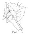
- FIG. 1is a plan view of a extended head humeral prosthesis according to the present invention shown in position implanted on a diseased humerus;
- FIG. 2is a plan view of a healthy humerus
- FIG. 3is a plan view of a diseased humerus
- FIG. 4is a plan view of a prior art humeral prosthesis
- FIG. 5is a plan view of a prior art humeral prosthesis shown in position implanted on a diseased humerus with the humerus shown in the retracted position;
- FIG. 6is a plan view of a prior art humeral prosthesis shown in position implanted on a diseased humerus with the humerus shown in the extended position with the humerus impinged on the distal acromion;
- FIG. 7is an enlarged plan view of the extended head humeral prosthesis of FIG. 1 ;
- FIG. 8is a plan view of the extended head humeral prosthesis of FIGS. 1 and 7 shown in position implanted on a diseased humerus and in cooperation with the glenoid cavity shown in the retracted position;
- FIG. 9is a plan view of the extended head humeral prosthesis of FIGS. 1 and 7 shown in position implanted on a diseased humerus and in cooperation with the glenoid cavity shown in the abducted position free from impingement in the glenoid cavity;
- FIG. 10is an enlarged plan view of the extended head humeral prosthesis of FIGS. 1 and 7 ;
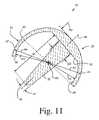
- FIG. 11is a cross sectional view of the extended head humeral prosthesis of FIG. 10 ;
- FIG. 12is an auxiliary view of the extended head humeral prosthesis of FIG. 10 along the lines 12 - 12 in the direction of the arrows;
- FIG. 13is a plan view of a reamer assembly to prepare a humeral head for the extended head humeral prosthesis of FIGS. 1 and 7 ;
- FIG. 14is a plan view, partially in cross section of a cutting guide for use with a cutter to prepare a humeral head for the extended head humeral prosthesis of FIGS. 1 and 7 ;
- FIG. 15is a top view of the cutting guide of FIG. 14 ;
- FIG. 16is plan view of a tool kit for preparing a humeral head for the extended head humeral prosthesis of FIGS. 1 and 7 ;
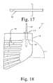
- FIG. 17is plan view of an end mill for preparing a humeral head for the extended head humeral prosthesis of FIGS. 1 and 7 ;
- FIG. 18is a plan view of another cutting guide for use with a cutter to prepare a humeral head for the extended head humeral prosthesis of FIGS. 1 and 7 ;
- FIG. 19is a top view of the cutting guide of FIG. 18 ;
- FIG. 20is plan view of another tool kit for preparing a humeral head for the extended head humeral prosthesis of FIGS. 1 and 7 ;
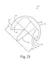
- FIG. 21is a plan view of another embodiment of a extended head humeral prosthesis according to the present invention.
- FIG. 22is a cross sectional view of the extended head humeral prosthesis of FIG. 21 ;
- FIG. 23is an auxiliary view of the extended head humeral prosthesis of FIG. 21 along the lines 23 - 23 in the direction of the arrows;
- FIG. 24is a plan view of a tool kit for preparing a humeral head for the extended head humeral prosthesis of FIGS. 21-23 ;
- FIG. 25is a process flow chart for a method of performing shoulder arthroplasty surgery according to another embodiment of the present invention.
- prosthesis 20is used in performing bone preserving joint arthroplasty.
- the prosthesis 20is to be fitted to the head of a long bone.
- the long bone as shown in FIG. 7is in the form of humerus 3 .
- the prosthesis 20includes a first body 22 having an articulating surface 24 defining a generally circular outer periphery 26 .
- the first body 22also includes a second surface 28 opposed to the articulating surface 24 .
- the second surface 28is adapted to receive the head of the humerus 3 .
- the prosthesis 20further includes a second body 30 operably associated with the first body 22 .
- the second body 30has a second body articulating surface 32 extending from a portion 34 of the circular periphery 26 of the first articulating surface 24 .
- the second body articulating surface 32is adapted to prevent impingement of the acromion 9 (see FIG. 1 ) with the humerus 3 when the humerus 3 is in the abducted position (see FIG. 8 ).
- the prosthesis 20further includes a stem 36 operably associated with the first body 22 or the second body 30 .
- the stem 36is associated with the first body 22 .
- the stem 36is adapted to assist in securing the prosthesis 20 to the humerus 3 .
- the prosthesis 20is an integral or one-piece item. It should be appreciated that the prosthesis 20 may be modular.
- the stem 36may be a separate component from the first body 22 or the second body 30 .
- the second body 30may be a separate component from the first body 22 .
- the first body 22may have any shape capable for articulating motion with the glenoid cavity (see FIG. 8 ), however, preferably the articulating surface 24 is generally convex.
- the articulating surface 24may be generally hemispherical.
- the second surface 28may likewise be generally hemispherical with the first body 22 being generally a hollow hemisphere.
- the second body articulating surface 32is preferably convex and may have a generally spherical shape.
- the second body second surface 38may likewise be generally spherical.
- the second body 30may thus also be generally a sector of a hollow sphere.
- boundary portion 40 of the prosthesis 20 located between the second articulating surface 32 and the first articulating surface 24 where the second articulating surface 32 extends from the first articulating surface 24is generally smooth and continuous.
- the prosthesis 20 of the present inventionis shown installed in the humerus 3 with the adjacent bones of the clavicle 8 , scapula 7 and acromion 9 shown in position.
- the humerus 3is abducted into an angle ⁇ with respect to vertical erect body reference line 42 .
- the acromion 9extends past the boundary portion 40 separating the first body 22 of the prosthesis 20 from the second body 30 of the prosthesis 20 .
- the second body articulating surface 32is utilized to prevent the acromion 9 from impinging on the humerus 3 .
- the humerus 3is again shown in position with the adjacent skeletal structure.
- the long bone or humerus 3is shown in position when the upper arm is in position against the torso.
- the angle ⁇ between the vertical centerline 42 and humeral centerline 44is represented by an angle ⁇ of approximately 15 degrees.
- the acromion 9is in contact with the first articulating surface 24 at acromion distal edge or outer edge 13 .
- the humerus 3is shown being abducted in the direction of arrow 46 with the respective angle ⁇ equaling approximately 60 degrees.
- the outer edge 13 of the acromion 9is in a position such that the second articulating surface 32 of the second body 30 is used to provide a smooth articulating surface for the outer edge 13 of the acromion 9 .
- the prosthesis 20is shown in greater detail. While the stem 36 of the prosthesis 20 may have any suitable shape capable of providing support for the prosthesis 20 in the humerus 3 , preferably, and as shown in FIG. 10 , the stem 36 has a general cylindrical shape.
- the first body 22 as shown in FIG. 10may be in the form of a hollow hemisphere having a first longitudinal body centerline 48 .
- the stem 36has a stem longitudinal centerline 50 .
- the prosthesis 20may be such that the first longitudinal body centerline 48 and the stem longitudinal centerline 50 are coincident. Such a configuration provides for a preferred central location of the stem 36 .
- the support surface opposed to the articulating surface 24 of the prosthesis 20may include at least part of the second surface 28 to include a support surface 52 opposed to the first articulating surface 24 .
- the support surfacemay be generally planar.
- the prosthesis 20may include a porous coating 53 secured to, for example, the second surface 28 of the first body 22 , the second surface 38 of the second body, the planar portion 52 of the second surface 28 , as well as on the periphery of the stem 36 .
- Any commercially available porous coatingwill assist in the bony ingrowth of the prosthesis 20 to the humerus 3 .
- One particular porous coatingis provided by the assignee of the instant application under the trade name POROCOATTM. Porous coating may be more fully understood by reference to U.S. Pat. No. 3,855,638 to Pilliar, hereby incorporated in its entireties by reference.
- the circular outer periphery 26 of the articulating surface 24 of the first body 22defines a first plane 54 .
- the second articulating surface 32 of the second body 30defines a second surface periphery 56 .
- the second surface periphery 56defines a second plane 58 .
- the first plane 54 and the second plane 58are non-coincident.
- the first plane 54 and the second plane 58therefore, define an angle ⁇ there between.
- the angle ⁇is obtuse. While the angle ⁇ may approach 180 degrees, the angle aa may likewise have a range of about 120 to 180 degrees. As shown in FIG. 20 , the angle aa may be around 138 degrees.
- the stem 36may be generally cylindrical having stem diameter SD and a length SL.
- the stem 36may be tapered and defined by an angle ⁇ .
- the angle ⁇may be around 5 to 30 degrees.
- the planar portion 52 of the prosthesis 20may have any reasonable location with respect to the articulating surface 24 of the prosthesis 20 .
- the proper position of the planar portion 52will depend on the flattening of the humeral head and how much corresponding amount of resection may be required to the humeral head.
- the position of the planar portion 52 with respect to the articulating surface 24may be defined by a flat dimension FD.
- the hemispherical body 22 and second body 30 of the prosthesis 20may be defined with respect to a prosthetic center point 60 .
- the articulating surface 24may be defined by a radius R 1 extending from center point 60 the articulating surface 24 .
- the second surface 28may be defined by a radius R 2 extending from the prosthetic center point 60 to the second surface 28 .
- the second articulating surface 32may be defined by radius R 4 from the prosthetic center point 60 to the second articulating surface 32 .
- the second surface of the second body 38may be defined by radius R 3 from the prosthetic center point 60 to the second surface 28 .
- the radii R 1 and R 4may be identical and for simplicity the radii R 2 and R 3 may be identical.
- FIG. 12the underside of the prosthesis 20 is shown.
- the prosthesis 20may have any size compatible with the humerus.
- the prosthesis 20preferably blends with the periphery of the humerus.
- the size of the prosthesis 20is governed generally by the size of the anatomical humerus.
- the prosthesis 20may be made of any suitable durable material that is compatible with the human anatomy.
- the prosthesis 20may be made of a ceramic, a plastic or a metal. If made of a metal, the prosthesis 20 may be made, for example, of a cobalt chromium alloy, a titanium alloy, or a stainless steel alloy.
- FIG. 16an instrument in the form of, for example, a reamer assembly 62 is shown for use in reaming, for example, the articulating surface 24 of the prosthesis 20 of FIG. 7 .
- the reamer assembly 62includes a tool driver 64 .
- the tool driver 64includes a body 66 having a cutting tool adaptor 68 and a drive adapter 70 .
- the reamer assembly 62also includes a reamer 72 .
- the reamer 72is connected to the tool driver 64 by the cutting tool adapter 68 .
- the reamer 72may be a hemispherical grater type reamer.
- the tool guide 74may include a body 76 having a cylindrical bore 78 for receiving a guide pin 80 and a elongated slot 82 for receiving a cutting tool in the form of osteotome 84 .
- the tool guide 74is used to prepare surface 88 of humerus 3 .
- a tool kit 86is shown for preparing a humerus to receive a prosthesis, for example, prosthesis 20 of FIGS. 7 through 12 .
- the prosthesis 20includes the first body 22 having the first articulating surface 24 and an opposed first surface support surface 28 .
- the prosthesis 20also includes the second body 30 that has the second articulating surface 32 and an opposed second support surface 38 .
- the kit 86is used for preparing the first support surface 28 and the second support surface 38 .
- the tool kit 86 of FIG. 16includes the reamer 72 and may include the tool driver 64 to form the reamer assembly 62 .
- the tool kit 86further includes a bone cutting tool 84 for preparing a second prepared surface on the humerus 3 for receiving the second support surface 38 of, for example, the prosthesis 20 .
- the bone cutting tool 84is used to prepare second prepared surface 88 on the humerus 3 .
- the second prepared surface 88represents the inside surface of a cylinder. Such a shape on the humerus is necessary to accommodate the inner edge 90 of the second body 30 of the prosthesis 20 . (See FIG. 11 ).
- the kit 86further includes the bone cutting tool guide 74 for guiding the osteotome 84 through the elongated slot 82 of the bone cutting tool guide 74 .
- the osteotome 84may be struck with mallet 96 .
- the guide 74 of the kit 86provides for a surface 88 that is generally cylindrical to permit the corner 90 of the prosthesis 20 to be fully seated into the humerus.
- the bone cutting tool necessary to prepare the humerusmay include a drill, a reamer, a broach, a saw or an osteotome.
- end mill 192is shown.
- End mill 192may be any commercially available milling cutter capable of end cutting.
- the guide 174includes a body 176 .
- the body 176includes an opening 178 for cooperation with location pin 180 .
- the location pin 180is used to orient the guide 174 with respect to the humerus 3 .
- the guide 174further defines a plurality of slots 182 formed in the body 176 .
- the slots 182extend an angle ⁇ about the periphery of concave inner surface 194 of the guide 174 .
- the slots 182are aligned somewhat parallel to each other and slightly spaced apart.
- the slots 182are close enough to minimize the amount of material not covered by the slots but far enough apart to provide enough strength to the guide 174 , particularly around the slots 182 .
- the kit 186includes reamer assembly 162 for preparing the first prepared surface on the humerus.
- the reamer assembly 162is similar to reamer assembly 62 of FIG. 13 and includes a tool driver 164 similar to the tool driver 64 of FIG. 13 as well as a grater type hemispherical reamer 172 similar to the reamer 72 of the reamer assembly 62 of FIG. 13 .
- the kit 20further includes end mill 192 as well as an osteotome 184 similar to osteotome 84 of the kit 86 of FIG. 16 .
- the osteotome 184serves to remove the material remaining after the end mill 192 removes materials in alignment with the slots 182 of the guide 174 .
- the kit 186may further include the guide 174 .
- the kit 20may include a surgical mallet 196 .
- the surgical mallet 196is used to strike the osteotome 184 .
- Prosthesis 120is similar to prosthesis 20 of FIGS. 7 through 12 except that prosthesis 120 is designed to take into consideration the limit in installing the prosthesis onto the prepared humeral head. Mainly, the prosthesis 120 takes into consideration the inability to clear the edge 90 of the prosthesis 20 when utilizing a spherically shaped humeral head.
- the prosthesis 120includes a first body 122 having a hemispherical articulating surface 124 and an opposed concave arcuate surface 128 .
- the first body 122also has a planar portion 152 opposing the articulating surface 124 .
- the prosthesis 120further includes a tapered cylindrical stem 136 extending inwardly from the planar portion 152 of the first body 122 .
- the prosthesis 120further includes a second body 130 extending from circular outer periphery 126 of the first body 122 .
- a boundary portion 140is located between the first body 122 and the second body 130 and is preferably smooth and continuous.
- the second body 130 of the prosthesis 120has an opposed surface in the form of a cylindrical inner periphery 138 .
- the cylindrical periphery 138is designed to matingly fit with the cylindrical surface prepared on the humeral head.
- the cylindrical periphery 138is shown in greater detail.
- the cylindrical periphery 138is defined by a radius R.sub.c extending from stem centerline 150 .
- FIG. 23another view of the cylindrical periphery 135 of the prosthesis 120 is shown.
- the cylindrical periphery 135is again defined by a radius R.sub.c from stem centerline 150 .
- the tool kit 286is used to prepare a humerus for the prosthesis of the present invention.
- the tool kit 286includes a reamer assembly 262 similar to the reamer assembly 162 of the kit 186 of FIG. 20 .
- the tool kit 286further includes a cylindrical end cutting reamer 292 having a cylindrical cutting surface 297 and a guiding surface 298 .
- the kit 286further includes a guide 274 for guiding the cylindrical reamer 292 in a proper path to properly prepare the humerus.
- the guide 274includes a body 276 defining an opening 278 for cooperation with location pin 280 , which is utilized to properly position the guide 274 on the humerus.
- the body 276 of the guide 274further includes an arcuate elongated slot 282 that cooperates with the guiding surface 298 of the reamer 292 to guide the reamer along a proper path.
- the arcuate slot 282is defined by an included angle ⁇ .
- the method 300includes the first step 302 of providing a prosthesis with a first body having a first articulating surface and an opposed first support surface and with a second body having a second articulating surface and an opposed second support surface.
- the method 300further includes a second step 304 providing a tool kit for preparing a humerus for receiving the prosthesis.
- the method 300further includes a third step 306 of preparing a first prepared surface for cooperation with the first support surface with the tool kit.
- the method 300also includes a fourth step 308 of preparing a second prepared surface for cooperation with the second support surface with the tool kit.
- the method 300further includes a fifth step 310 of implanting the prosthesis onto the first prepared surface and the second prepared surface.
Landscapes
- Health & Medical Sciences (AREA)
- Life Sciences & Earth Sciences (AREA)
- Surgery (AREA)
- Veterinary Medicine (AREA)
- Animal Behavior & Ethology (AREA)
- Public Health (AREA)
- Oral & Maxillofacial Surgery (AREA)
- Engineering & Computer Science (AREA)
- Biomedical Technology (AREA)
- Heart & Thoracic Surgery (AREA)
- General Health & Medical Sciences (AREA)
- Orthopedic Medicine & Surgery (AREA)
- Molecular Biology (AREA)
- Nuclear Medicine, Radiotherapy & Molecular Imaging (AREA)
- Medical Informatics (AREA)
- Dentistry (AREA)
- Transplantation (AREA)
- Cardiology (AREA)
- Vascular Medicine (AREA)
- Physical Education & Sports Medicine (AREA)
- Prostheses (AREA)
Abstract
Description
Claims (20)
Priority Applications (4)
| Application Number | Priority Date | Filing Date | Title |
|---|---|---|---|
| US12/421,335US8444646B2 (en) | 2003-03-31 | 2009-04-09 | Bone preparation tool kit and associated method |
| US13/874,958US8814943B2 (en) | 2003-03-31 | 2013-05-01 | Bone preparation tool kit and associated method |
| US14/449,284US9107758B2 (en) | 2003-03-31 | 2014-08-01 | Bone preparation tool kit and associated method |
| US14/807,042US9445911B2 (en) | 2003-03-31 | 2015-07-23 | Bone preparation tool kit and associated method |
Applications Claiming Priority (2)
| Application Number | Priority Date | Filing Date | Title |
|---|---|---|---|
| US10/403,708US7517364B2 (en) | 2003-03-31 | 2003-03-31 | Extended articulation orthopaedic implant and associated method |
| US12/421,335US8444646B2 (en) | 2003-03-31 | 2009-04-09 | Bone preparation tool kit and associated method |
Related Parent Applications (1)
| Application Number | Title | Priority Date | Filing Date |
|---|---|---|---|
| US10/403,708DivisionUS7517364B2 (en) | 2003-03-31 | 2003-03-31 | Extended articulation orthopaedic implant and associated method |
Related Child Applications (1)
| Application Number | Title | Priority Date | Filing Date |
|---|---|---|---|
| US13/874,958DivisionUS8814943B2 (en) | 2003-03-31 | 2013-05-01 | Bone preparation tool kit and associated method |
Publications (2)
| Publication Number | Publication Date |
|---|---|
| US20090198238A1 US20090198238A1 (en) | 2009-08-06 |
| US8444646B2true US8444646B2 (en) | 2013-05-21 |
Family
ID=32850574
Family Applications (6)
| Application Number | Title | Priority Date | Filing Date |
|---|---|---|---|
| US10/403,708Expired - LifetimeUS7517364B2 (en) | 2003-03-31 | 2003-03-31 | Extended articulation orthopaedic implant and associated method |
| US12/421,308Expired - LifetimeUS8182541B2 (en) | 2003-03-31 | 2009-04-09 | Extended articulation orthopaedic implant |
| US12/421,335Expired - LifetimeUS8444646B2 (en) | 2003-03-31 | 2009-04-09 | Bone preparation tool kit and associated method |
| US13/874,958Expired - LifetimeUS8814943B2 (en) | 2003-03-31 | 2013-05-01 | Bone preparation tool kit and associated method |
| US14/449,284Expired - Fee RelatedUS9107758B2 (en) | 2003-03-31 | 2014-08-01 | Bone preparation tool kit and associated method |
| US14/807,042Expired - Fee RelatedUS9445911B2 (en) | 2003-03-31 | 2015-07-23 | Bone preparation tool kit and associated method |
Family Applications Before (2)
| Application Number | Title | Priority Date | Filing Date |
|---|---|---|---|
| US10/403,708Expired - LifetimeUS7517364B2 (en) | 2003-03-31 | 2003-03-31 | Extended articulation orthopaedic implant and associated method |
| US12/421,308Expired - LifetimeUS8182541B2 (en) | 2003-03-31 | 2009-04-09 | Extended articulation orthopaedic implant |
Family Applications After (3)
| Application Number | Title | Priority Date | Filing Date |
|---|---|---|---|
| US13/874,958Expired - LifetimeUS8814943B2 (en) | 2003-03-31 | 2013-05-01 | Bone preparation tool kit and associated method |
| US14/449,284Expired - Fee RelatedUS9107758B2 (en) | 2003-03-31 | 2014-08-01 | Bone preparation tool kit and associated method |
| US14/807,042Expired - Fee RelatedUS9445911B2 (en) | 2003-03-31 | 2015-07-23 | Bone preparation tool kit and associated method |
Country Status (6)
| Country | Link |
|---|---|
| US (6) | US7517364B2 (en) |
| EP (1) | EP1464305B1 (en) |
| AT (1) | ATE547070T1 (en) |
| AU (2) | AU2004201349B2 (en) |
| DK (1) | DK1464305T3 (en) |
| ES (1) | ES2379783T3 (en) |
Cited By (14)
| Publication number | Priority date | Publication date | Assignee | Title |
|---|---|---|---|---|
| US20140343680A1 (en)* | 2003-03-31 | 2014-11-20 | DePuy Synthes Products, LLC | Bone preparation tool kit and associated method |
| US8974458B2 (en) | 2003-03-31 | 2015-03-10 | DePuy Synthes Products, LLC | Arthroplasty instruments and associated method |
| USD746989S1 (en) | 2013-10-31 | 2016-01-05 | Catalyst Orthopaedics Llc | Implant |
| US9289306B2 (en) | 2013-03-15 | 2016-03-22 | Catalyst Orthopaedics Llc | Humeral arthroplasty |
| USD759819S1 (en) | 2013-03-11 | 2016-06-21 | Catalyst Orthopaedics Llc | Glenoid implant |
| US9814588B2 (en) | 2015-08-10 | 2017-11-14 | Catalyst Orthoscience Inc. | Glenoid arthroplasty with multi-directional fixation |
| US9814471B2 (en) | 2013-03-11 | 2017-11-14 | Catalyst Orthoscience Inc. | Glenoid arthroplasty and offset reamers |
| US9849000B2 (en) | 2003-03-31 | 2017-12-26 | DePuy Synthes Products, Inc. | Punch, implant and associated method |
| US10335169B2 (en) | 2015-09-14 | 2019-07-02 | Symmetry Medical Manufacturing, Inc. | Angled orthopaedic driver |
| USD898914S1 (en)* | 2018-12-05 | 2020-10-13 | Medline Industries, Inc. | Bone preparation tool |
| US10973646B2 (en) | 2013-03-11 | 2021-04-13 | Catalyst Orthoscience Inc. | Stabilized drill guide |
| US11007063B2 (en) | 2013-03-11 | 2021-05-18 | Catalyst Orthoscience Inc. | Offset reamers |
| US11007064B2 (en) | 2015-08-10 | 2021-05-18 | Catalyst Orthoscience Inc. | Arthroplasty prostheses with multi-axis fixation |
| US12268610B2 (en) | 2020-05-07 | 2025-04-08 | Howmedica Osteonics Corp. | Stemless metaphyseal humeral implant |
Families Citing this family (101)
| Publication number | Priority date | Publication date | Assignee | Title |
|---|---|---|---|---|
| US6793678B2 (en) | 2002-06-27 | 2004-09-21 | Depuy Acromed, Inc. | Prosthetic intervertebral motion disc having dampening |
| AU2004212942A1 (en) | 2003-02-14 | 2004-09-02 | Depuy Spine, Inc. | In-situ formed intervertebral fusion device |
| US7887544B2 (en) | 2003-03-10 | 2011-02-15 | Tornier Sas | Ancillary tool for positioning a glenoid implant |
| US20040193278A1 (en)* | 2003-03-31 | 2004-09-30 | Maroney Brian J. | Articulating surface replacement prosthesis |
| US8545506B2 (en) | 2003-03-31 | 2013-10-01 | DePuy Synthes Products, LLC | Cutting guide for use with an extended articulation orthopaedic implant |
| US7527631B2 (en) | 2003-03-31 | 2009-05-05 | Depuy Products, Inc. | Arthroplasty sizing gauge |
| US20040267367A1 (en) | 2003-06-30 | 2004-12-30 | Depuy Acromed, Inc | Intervertebral implant with conformable endplate |
| US7585327B2 (en)* | 2003-09-24 | 2009-09-08 | Biomet Manufacturing Corp. | Extended articular surface resurfacing head |
| FR2863865B1 (en) | 2003-12-19 | 2006-10-06 | Tornier Sa | SHOULDER OR HIP PROSTHESIS AND METHOD OF MOUNTING |
| US7879042B2 (en)* | 2004-03-05 | 2011-02-01 | Depuy Products, Inc. | Surface replacement extractor device and associated method |
| US8636802B2 (en) | 2004-03-06 | 2014-01-28 | DePuy Synthes Products, LLC | Dynamized interspinal implant |
| US7678150B2 (en) | 2004-06-15 | 2010-03-16 | Tornier Sas | Total shoulder prosthesis of an inverted type |
| FR2871371B1 (en) | 2004-06-15 | 2007-04-06 | Tornier Sas | GLENOIDAL COMPONENT OF SHOULDER PROSTHESIS, SET OF COMPONENT ELEMENTS OF SUCH COMPONENT AND TOTAL SHOULDER PROSTHESIS INCORPORATING SUCH COMPONENT |
| US8303665B2 (en) | 2004-06-15 | 2012-11-06 | Tornier Sas | Glenoidal component, set of such components and shoulder prosthesis incorporating such a glenoidal component |
| FR2872025B1 (en) | 2004-06-28 | 2006-08-25 | Tornier Sas | PROSTHESIS OF SHOULDER OR HIP |
| US20060069445A1 (en)* | 2004-09-27 | 2006-03-30 | Ondrla Jeffrey M | Extended articulation prosthesis adaptor and associated method |
| US7892287B2 (en)* | 2004-09-27 | 2011-02-22 | Depuy Products, Inc. | Glenoid augment and associated method |
| US20060074353A1 (en)* | 2004-09-27 | 2006-04-06 | Deffenbaugh Daren L | Glenoid instrumentation and associated method |
| US7922769B2 (en)* | 2004-09-27 | 2011-04-12 | Depuy Products, Inc. | Modular glenoid prosthesis and associated method |
| US7927335B2 (en) | 2004-09-27 | 2011-04-19 | Depuy Products, Inc. | Instrument for preparing an implant support surface and associated method |
| US8778028B2 (en) | 2005-02-25 | 2014-07-15 | Shoulder Innovations, Inc. | Methods and devices for less invasive glenoid replacement |
| US8007538B2 (en)* | 2005-02-25 | 2011-08-30 | Shoulder Innovations, Llc | Shoulder implant for glenoid replacement |
| US20230080207A1 (en) | 2005-02-25 | 2023-03-16 | Shoulder Innovations, Inc. | Methods and devices for less invasive glenoid replacement |
| CA2621019A1 (en)* | 2005-08-31 | 2007-03-08 | Zimmer Gmbh | Implant |
| US20070198094A1 (en)* | 2006-02-17 | 2007-08-23 | Biomet Manufacturing Corp. | Adaptor prosthesis kit |
| FR2898267B1 (en)* | 2006-03-10 | 2008-12-26 | Michel Timoteo | IMPLANT RE-SURFACING OF FEMALE HEAD AND ITS ANCILLARY. |
| EP1996123B1 (en) | 2006-03-21 | 2019-08-28 | Tornier, Inc. | Non-spherical articulating surfaces in shoulder and hip prosthesis |
| WO2007109319A2 (en) | 2006-03-21 | 2007-09-27 | Axiom Orthopaedics, Inc. | Glenoid component with improved fixation stability |
| WO2007109340A2 (en)* | 2006-03-21 | 2007-09-27 | Axiom Orthopaedics, Inc. | Femoral and humeral stem geometry and implantation method for orthopedic joint reconstruction |
| FR2899790B1 (en)* | 2006-04-13 | 2008-06-13 | Tornier Sas | GLENOIDAL COMPONENT FOR TOTAL SHOULDER PROSTHESIS, SET OF SUCH COMPONENTS, AND TOTAL SHOULDER PROSTHESIS COMPRISING SUCH A COMPONENT |
| FR2900045B1 (en) | 2006-04-21 | 2009-01-16 | Tornier Sas | PROSTHESIS OF SHOULDER OR HIP |
| US20080021564A1 (en)* | 2006-07-20 | 2008-01-24 | Gunther Stephen B | Humeral head resurfacing implant and methods of use thereof |
| US20080109085A1 (en) | 2006-11-03 | 2008-05-08 | Howmedica Osteonics Corp. | Method and apparatus for hip femoral resurfacing tooling |
| WO2008070863A2 (en) | 2006-12-07 | 2008-06-12 | Interventional Spine, Inc. | Intervertebral implant |
| US20090287309A1 (en) | 2007-01-30 | 2009-11-19 | Tornier Sas | Intra-articular joint replacement |
| FR2911773B1 (en) | 2007-01-30 | 2009-03-27 | Tornier Sas | METHOD AND ASSEMBLY OF SURGICAL INSTRUMENTATION FOR POSITIONING A TOTAL REVERSE SHOULDER PROSTHESIS, AND CORRESPONDING PROSTHESIS |
| ITUD20070089A1 (en)* | 2007-05-25 | 2008-11-26 | Lima Lto S P A | HOMERAL PROSTHESIS FOR THE ARTICULATION OF THE SHOULDER |
| US8900307B2 (en) | 2007-06-26 | 2014-12-02 | DePuy Synthes Products, LLC | Highly lordosed fusion cage |
| EP2237748B1 (en) | 2008-01-17 | 2012-09-05 | Synthes GmbH | An expandable intervertebral implant |
| US8114087B2 (en)* | 2008-04-04 | 2012-02-14 | Depuy Products, Inc. | Humeral rotating burr guide |
| US8936641B2 (en) | 2008-04-05 | 2015-01-20 | DePuy Synthes Products, LLC | Expandable intervertebral implant |
| US8241365B2 (en) | 2008-12-23 | 2012-08-14 | Depuy Products, Inc. | Shoulder prosthesis with vault-filling structure having bone-sparing configuration |
| EP3610809B1 (en)* | 2009-01-23 | 2021-07-14 | Synthes GmbH | Jig and saw guides for use in osteotomies |
| US9545311B2 (en) | 2009-03-05 | 2017-01-17 | Tornier, Inc. | Glenoid implant anchor post |
| US9526620B2 (en) | 2009-03-30 | 2016-12-27 | DePuy Synthes Products, Inc. | Zero profile spinal fusion cage |
| GB2471290A (en)* | 2009-06-23 | 2010-12-29 | Keith Borowsky | Joint repair apparatus |
| US8246687B2 (en) | 2009-11-18 | 2012-08-21 | Biomet Manufacturing Corp. | Shoulder prosthetic |
| US8231683B2 (en) | 2009-12-08 | 2012-07-31 | Depuy Products, Inc. | Shoulder prosthesis assembly having glenoid rim replacement structure |
| US9393129B2 (en) | 2009-12-10 | 2016-07-19 | DePuy Synthes Products, Inc. | Bellows-like expandable interbody fusion cage |
| AU2010337239B2 (en) | 2009-12-14 | 2015-08-27 | Ascension Orthopedics, Inc. | Humeral head resurfacing implant |
| US9408652B2 (en) | 2010-04-27 | 2016-08-09 | Tornier Sas | Intra-articular joint replacement and method |
| US8979860B2 (en) | 2010-06-24 | 2015-03-17 | DePuy Synthes Products. LLC | Enhanced cage insertion device |
| US9907560B2 (en) | 2010-06-24 | 2018-03-06 | DePuy Synthes Products, Inc. | Flexible vertebral body shavers |
| US8623091B2 (en) | 2010-06-29 | 2014-01-07 | DePuy Synthes Products, LLC | Distractible intervertebral implant |
| USD685474S1 (en) | 2010-07-06 | 2013-07-02 | Tornier, Inc. | Prosthesis anchor |
| US9402732B2 (en) | 2010-10-11 | 2016-08-02 | DePuy Synthes Products, Inc. | Expandable interspinous process spacer implant |
| FR2966343B1 (en) | 2010-10-22 | 2012-12-07 | Tornier Sa | SET OF GLENOIDIAN COMPONENTS OF SHOULDER PROSTHESIS |
| US8480750B2 (en) | 2010-11-24 | 2013-07-09 | DePuy Synthes Products, LLC | Modular glenoid prosthesis |
| US8465548B2 (en) | 2010-11-24 | 2013-06-18 | DePuy Synthes Products, LLC | Modular glenoid prosthesis |
| US9381086B2 (en) | 2010-11-30 | 2016-07-05 | Shoulder Innovations, Llc | Stem for use in joint arthroplasty |
| US9211188B2 (en)* | 2011-07-15 | 2015-12-15 | Derek James Wallace McMinn | Femoral head prosthesis |
| FR2978912A1 (en) | 2011-08-10 | 2013-02-15 | Tornier Inc | ANCILLARY EXTRACTION OF A PROSTHESIS |
| US9730797B2 (en)* | 2011-10-27 | 2017-08-15 | Toby Orthopaedics, Inc. | Bone joint replacement and repair assembly and method of repairing and replacing a bone joint |
| US9717601B2 (en) | 2013-02-28 | 2017-08-01 | DePuy Synthes Products, Inc. | Expandable intervertebral implant, system, kit and method |
| US9522070B2 (en) | 2013-03-07 | 2016-12-20 | Interventional Spine, Inc. | Intervertebral implant |
| US10456264B2 (en) | 2014-01-24 | 2019-10-29 | Tornier, Inc. | Humeral implant anchor system |
| US12023253B2 (en) | 2014-01-24 | 2024-07-02 | Howmedica Osteonics Corp. | Humeral implant anchor system |
| US9681960B2 (en) | 2014-05-16 | 2017-06-20 | Howmedica Osteonics Corp. | Guides for fracture system |
| US10575968B2 (en) | 2014-05-16 | 2020-03-03 | Howmedica Osteonics Corp. | Guides for fracture system |
| US10492926B1 (en) | 2014-09-04 | 2019-12-03 | Shoulder Innovations, Inc. | Alignment guide for humeral or femoral stem replacement prostheses |
| US11426290B2 (en) | 2015-03-06 | 2022-08-30 | DePuy Synthes Products, Inc. | Expandable intervertebral implant, system, kit and method |
| WO2016149792A1 (en) | 2015-03-23 | 2016-09-29 | Johnston David Gerald | Orthopaedic shoulder implant |
| US10463499B2 (en) | 2016-03-25 | 2019-11-05 | Tornier, Inc. | Stemless shoulder implant with fixation components |
| CN109475385B (en) | 2016-06-17 | 2021-06-18 | 捷迈有限公司 | System and method for intraoperative surgical planning |
| EP3474784A2 (en) | 2016-06-28 | 2019-05-01 | Eit Emerging Implant Technologies GmbH | Expandable and angularly adjustable intervertebral cages with articulating joint |
| US11510788B2 (en) | 2016-06-28 | 2022-11-29 | Eit Emerging Implant Technologies Gmbh | Expandable, angularly adjustable intervertebral cages |
| US11129724B2 (en) | 2016-07-28 | 2021-09-28 | Howmedica Osteonics Corp. | Stemless prosthesis anchor component |
| US10888433B2 (en) | 2016-12-14 | 2021-01-12 | DePuy Synthes Products, Inc. | Intervertebral implant inserter and related methods |
| EP4520302A3 (en) | 2017-04-14 | 2025-04-16 | Shoulder Innovations, Inc. | Total shoulder prosthesis having inset glenoid implant convertible from anatomic to reverse |
| US10398563B2 (en) | 2017-05-08 | 2019-09-03 | Medos International Sarl | Expandable cage |
| US11344424B2 (en) | 2017-06-14 | 2022-05-31 | Medos International Sarl | Expandable intervertebral implant and related methods |
| US10940016B2 (en) | 2017-07-05 | 2021-03-09 | Medos International Sarl | Expandable intervertebral fusion cage |
| MX2020003194A (en) | 2017-09-25 | 2020-12-09 | Howmedica Osteonics Corp | Patient specific stemless prosthesis anchor components. |
| US20220047394A1 (en)* | 2017-11-01 | 2022-02-17 | Matortho Limited | Improvements in or relating to ceramic femoral resurfacing head prosthesis |
| US11399948B2 (en) | 2017-12-11 | 2022-08-02 | Howmedica Osteonics Corp. | Stemless prosthesis anchor components and kits |
| US12138172B2 (en) | 2018-04-30 | 2024-11-12 | Shoulder Innovations, Inc. | Inset/onlay glenoid, porous coated convertible glenoid, and humeral heads with textured undersides |
| US10813769B2 (en) | 2018-07-24 | 2020-10-27 | DePuy Synthes Products, Inc. | Baseplate of a modular shoulder joint prosthesis and related methods for implanting the same |
| EP4257090A3 (en) | 2018-10-02 | 2023-12-13 | Howmedica Osteonics Corp. | Shoulder prosthesis components and assemblies |
| WO2020070244A1 (en) | 2018-10-04 | 2020-04-09 | Depuy Ireland Unlimited Company | Prosthesis extraction system |
| US11446156B2 (en) | 2018-10-25 | 2022-09-20 | Medos International Sarl | Expandable intervertebral implant, inserter instrument, and related methods |
| AU2020237088B2 (en) | 2019-03-11 | 2025-09-04 | Shoulder Innovations, Inc. | Total reverse shoulder systems and methods |
| USD977643S1 (en) | 2019-03-12 | 2023-02-07 | Shoulder Innovations, Inc. | Humeral stem implant |
| USD951449S1 (en) | 2019-10-01 | 2022-05-10 | Howmedica Osteonics Corp. | Humeral implant |
| EP4527357A3 (en) | 2019-10-01 | 2025-06-04 | Howmedica Osteonics Corporation | Shoulder prosthesis components and assemblies |
| US12232970B2 (en)* | 2019-12-26 | 2025-02-25 | Eduardo Gonzalez-Hernandez | Implant facilitating upper humerus resurfacing and method for use and implantation thereof |
| US11426286B2 (en) | 2020-03-06 | 2022-08-30 | Eit Emerging Implant Technologies Gmbh | Expandable intervertebral implant |
| CN111870307B (en)* | 2020-07-07 | 2022-04-22 | 中南大学湘雅医院 | Rotator cuff patching device |
| US11850160B2 (en) | 2021-03-26 | 2023-12-26 | Medos International Sarl | Expandable lordotic intervertebral fusion cage |
| US11752009B2 (en) | 2021-04-06 | 2023-09-12 | Medos International Sarl | Expandable intervertebral fusion cage |
| US12090064B2 (en) | 2022-03-01 | 2024-09-17 | Medos International Sarl | Stabilization members for expandable intervertebral implants, and related systems and methods |
| CN120168044B (en)* | 2025-05-22 | 2025-08-05 | 四川大学 | Temporomandibular joint prosthesis replacement operation auxiliary positioning tool |
Citations (151)
| Publication number | Priority date | Publication date | Assignee | Title |
|---|---|---|---|---|
| US788362A (en) | 1904-07-14 | 1905-04-25 | Henry C Lavery | Anatomical measuring and recording machine. |
| US1023542A (en) | 1910-09-14 | 1912-04-16 | Winter Kunststoff Heinr J | Instrument for measuring bodies. |
| US1345443A (en) | 1918-07-27 | 1920-07-06 | Hood Henry | Screwdriver |
| US1669701A (en) | 1926-02-05 | 1928-05-15 | Estwing Mfg Company Inc | Method of and apparatus for manufacturing nail hammers having integral shanks |
| US2200120A (en) | 1938-04-30 | 1940-05-07 | Walter W Nauth | Fracture nail guide |
| US2222517A (en) | 1938-12-08 | 1940-11-19 | James W Price | Fracture nail and machine for making same |
| US2243718A (en) | 1938-11-05 | 1941-05-27 | Moreira Francisco Elias Godoy | Surgical drill |
| US2718228A (en) | 1952-09-26 | 1955-09-20 | Henri Georges Van Steenbrugghe | Artificial femoral heads in prostheses |
| US2725878A (en) | 1954-09-20 | 1955-12-06 | Union Broach Co Inc | Surgical mallet structure |
| GB764600A (en) | 1954-04-28 | 1956-12-28 | Pryor & Howard Ltd | An appliance for use as a femoral prosthesis |
| US2804895A (en) | 1955-11-14 | 1957-09-03 | Eldon W Clement | Counterbore attachment for drills |
| US2934065A (en) | 1954-11-01 | 1960-04-26 | Zimmer Mfg Company | Femoral intramedullary prosthesis |
| US3002514A (en) | 1958-01-24 | 1961-10-03 | Deyerle William Minor | Hip setting pin |
| US3605527A (en) | 1969-06-03 | 1971-09-20 | Gambale And Merrill Corp | Method for manufacturing hip reamers |
| US3702611A (en) | 1971-06-23 | 1972-11-14 | Meyer Fishbein | Surgical expansive reamer for hip socket |
| US3840904A (en) | 1973-04-30 | 1974-10-15 | R Tronzo | Acetabular cup prosthesis |
| US3855638A (en) | 1970-06-04 | 1974-12-24 | Ontario Research Foundation | Surgical prosthetic device with porous metal coating |
| US3979778A (en) | 1976-01-14 | 1976-09-14 | Stroot Jerome H | Shoulder prosthesis |
| US4042980A (en) | 1975-03-13 | 1977-08-23 | National Research Development Corporation | Endoprosthetic shoulder joint device |
| US4206517A (en) | 1977-12-01 | 1980-06-10 | Biomedical Engineering Corp. | Floating center prosthetic joint |
| US4271849A (en) | 1978-08-04 | 1981-06-09 | Orthoplant Orthopadische Implantate Gmbh & Co. | Apparatus for producing relief grooves in pan-shaped bones |
| US4274164A (en) | 1978-08-04 | 1981-06-23 | Orthoplant Orthopadische Implantate Gmbh & Co. Kg | Endoprosthesis for a hip joint, especially for the hip joint of a human being |
| DE2041929C3 (en) | 1969-08-25 | 1981-09-03 | National Research Development Corp., London | Cup for a shoulder joint prosthesis |
| US4328593A (en) | 1979-12-22 | 1982-05-11 | Institut Straumann Ag | Universal joint prosthesis with cap |
| US4335429A (en) | 1979-03-20 | 1982-06-15 | Daihatsu Motor Co., Ltd. | Control apparatus for engine/electric hybrid vehicle |
| US4355429A (en) | 1979-01-26 | 1982-10-26 | Osteo Ag | Slide prosthesis for the knee joint |
| US4432358A (en) | 1982-01-22 | 1984-02-21 | Fixel Irving E | Compression hip screw apparatus |
| US4441492A (en) | 1982-09-29 | 1984-04-10 | Nils Rydell | Aid for telescopic nail for orthopedic use |
| FR2418664B1 (en) | 1978-03-03 | 1984-04-13 | Schleicher & Schuell Gmbh | |
| US4502474A (en) | 1981-08-20 | 1985-03-05 | Comparetto John E | Bone wedge guidance system |
| US4550450A (en) | 1984-07-24 | 1985-11-05 | Kinnett James G | Total shoulder prosthesis system |
| FR2418644B1 (en) | 1978-03-02 | 1986-06-06 | Grammont Paul Marie | TOTAL TROCHITERO-ACROMIAL SHOULDER PROSTHESIS |
| US4601289A (en) | 1985-04-02 | 1986-07-22 | Dow Corning Wright | Femoral trial prosthesis/rasp assembly |
| FR2578739A1 (en) | 1985-03-12 | 1986-09-19 | Rambert Andre | Humeral prosthesis |
| US4714471A (en) | 1984-09-26 | 1987-12-22 | S + G Implants Gmbh | Femur prosthesis part of a knee joint endoprosthesis |
| US4722330A (en) | 1986-04-22 | 1988-02-02 | Dow Corning Wright Corporation | Femoral surface shaping guide for knee implants |
| US4752296A (en) | 1983-05-06 | 1988-06-21 | Buechel Frederick F | Prosthesis with interlocking fixation and providing reduction of stress shielding |
| US4787378A (en) | 1986-09-08 | 1988-11-29 | Sodhi Jitendra S | Self-retaining nail for fracture of neck of femur |
| US4795473A (en) | 1987-01-09 | 1989-01-03 | Grimes James B | Extramedullary femoral head-neck prosthesis and method of implanting same |
| US4801289A (en) | 1987-07-15 | 1989-01-31 | Tsubakimoto Chain Co. | Rocker pin type continuously variable transmission chain |
| US4805607A (en) | 1987-12-03 | 1989-02-21 | Boehringer Mannheim Corporation | Modular intramedullary nail system |
| US4846841A (en) | 1986-04-25 | 1989-07-11 | Indong Oh | Femoral Prosthesis |
| US4865605A (en) | 1988-02-02 | 1989-09-12 | Dines David M | Modular shoulder prosthesis |
| US4865609A (en) | 1988-03-02 | 1989-09-12 | Bioconcepts, Inc. | Modular joint prosthesis assembly and method of removing |
| US4893619A (en) | 1988-02-04 | 1990-01-16 | Intermedics Orthopedics, Inc. | Humeral osteotomy guide |
| US4919669A (en) | 1987-02-09 | 1990-04-24 | Jean Lannelongue | Shoulder prosthesis |
| US4987904A (en) | 1990-03-22 | 1991-01-29 | Wilson James T | Method and apparatus for bone size gauging |
| US4995883A (en) | 1989-02-08 | 1991-02-26 | Smith & Nephew Richards Inc. | Modular hip prosthesis |
| US5041117A (en) | 1989-08-31 | 1991-08-20 | Boehringer Mannheim Corporation | Elbow arthroplasty instrumentation and surgical procedure |
| US5064427A (en) | 1991-05-14 | 1991-11-12 | Intermedics Orthopedics, Inc. | Apparatus for inserting and withdrawing humeral prosthesis |
| US5070623A (en) | 1990-05-02 | 1991-12-10 | Zimmer, Inc. | Prosthetic gauge |
| US5108396A (en) | 1990-06-07 | 1992-04-28 | Smith & Nephew Richards Inc. | Intramedullary referenced humeral head resection guide |
| US5116339A (en) | 1990-07-11 | 1992-05-26 | Glock Steven R | Acetabular cup installation tool and method of installing an acetabular cup |
| US5141520A (en) | 1991-10-29 | 1992-08-25 | Marlowe Goble E | Harpoon suture anchor |
| DE4228710A1 (en) | 1991-09-03 | 1993-03-04 | Zimmer Inc | Modular implant system assembled during operation - has solid plastic between components gluing them together when activated, reduces wear and avoids need for liq. cement |
| US5226915A (en) | 1992-04-03 | 1993-07-13 | Bertin Kim C | Femoral prosthesis component system for knee replacement surgery |
| US5250051A (en) | 1993-02-08 | 1993-10-05 | Zimmer, Inc. | Acetabular cup positioner with slaphammer mechanism for the removal of the sighting guide |
| US5258033A (en) | 1990-08-08 | 1993-11-02 | Howmedica International Inc. | Total hip replacement femoral component |
| US5282865A (en) | 1992-06-22 | 1994-02-01 | Osteonics Corp. | Humeral shoulder prosthesis |
| US5312411A (en)* | 1992-10-27 | 1994-05-17 | Smith & Nephew Richards, Inc. | Uni-compartmental femoral knee instruments and prosthesis |
| US5314479A (en) | 1986-08-15 | 1994-05-24 | Depuy Inc. | Modular prosthesis |
| US5358525A (en) | 1992-12-28 | 1994-10-25 | Fox John E | Bearing surface for prosthesis and replacement of meniscal cartilage |
| US5374269A (en) | 1990-01-31 | 1994-12-20 | American Cyanamid Company | Method and instruments for ACL reconstruction |
| DE4220217C2 (en) | 1992-06-20 | 1995-02-23 | S & G Implants Gmbh | Endoprosthesis |
| US5405349A (en)* | 1993-11-24 | 1995-04-11 | Intermedics Orthopedics, Inc. | Cutting jig for posterior stabilized knee prosthesis |
| US5423827A (en) | 1994-06-02 | 1995-06-13 | Intermedics Orthopedics, Inc. | Surgical jig for femoral knee prosthesis |
| US5454816A (en) | 1992-02-07 | 1995-10-03 | Howmedica International Inc. | Femoral cutting guide |
| US5470336A (en) | 1990-08-10 | 1995-11-28 | Ling; Robin S. M. | System for performing hip prosthesis revision surgery |
| US5476467A (en) | 1994-06-14 | 1995-12-19 | Benoist; Louis A. | Surgical hammer for driving K-wires |
| US5486178A (en) | 1994-02-16 | 1996-01-23 | Hodge; W. Andrew | Femoral preparation instrumentation system and method |
| US5490852A (en) | 1994-02-16 | 1996-02-13 | Azer; Samir N. | Orthopedic awl |
| US5507817A (en) | 1994-02-22 | 1996-04-16 | Kirschner Medical Corporation | Modular humeral prosthesis for reconstruction of the humerus |
| US5514139A (en) | 1994-09-02 | 1996-05-07 | Hudson Surgical Design, Inc. | Method and apparatus for femoral resection |
| US5540696A (en) | 1995-01-06 | 1996-07-30 | Zimmer, Inc. | Instrumentation for use in orthopaedic surgery |
| US5549704A (en) | 1994-09-08 | 1996-08-27 | Sutter; Franz | Universal joint prosthesis |
| US5569263A (en) | 1995-01-12 | 1996-10-29 | Orthopaedic Innovations, Inc. | Adjustable provisional articulating device |
| US5662476A (en) | 1992-06-29 | 1997-09-02 | Nobel Biocare Ab | Prosthetic implant restoration method |
| FR2737107B1 (en) | 1995-07-26 | 1997-09-05 | Medinov Sa | ASSEMBLY DEVICE BETWEEN TWO PARTS OF A PROSTHETIC ELEMENT IN PARTICULAR |
| US5683395A (en) | 1996-04-26 | 1997-11-04 | Mikhail; W. E. Michael | System for performing hip prothesis revision surgery |
| US5690636A (en) | 1995-12-21 | 1997-11-25 | Johnson & Johnson Professional, Inc. | Punch system for tibial prosthesis |
| US5702460A (en) | 1995-02-15 | 1997-12-30 | Smith & Nephew, Inc. | Revision femoral trial prosthesis |
| US5723018A (en) | 1992-11-17 | 1998-03-03 | Cyprien; Jean-Maxwell | Shoulder-joint endoprosthesis |
| US5735905A (en) | 1995-04-27 | 1998-04-07 | Southwest Research Institute | Shock absorbing element for a load bearing prosthesis |
| EP0845250A2 (en) | 1996-11-30 | 1998-06-03 | Depuy International Limited | An osteoprosthesis component |
| US5769852A (en) | 1993-04-27 | 1998-06-23 | Medevelop Ab | Implantable anchoring element and anchoring assembly for prostheses |
| US5776194A (en) | 1996-04-25 | 1998-07-07 | Nuvana Medical Innovations, Llc | Intermedullary rod apparatus and methods of repairing proximal humerus fractures |
| US5776201A (en) | 1995-10-02 | 1998-07-07 | Johnson & Johnson Professional, Inc. | Modular femoral trial system |
| US5779710A (en) | 1996-06-21 | 1998-07-14 | Matsen, Iii; Frederick A. | Joint replacement method and apparatus |
| US5800557A (en) | 1994-05-02 | 1998-09-01 | Elhami; Laghaollah | Joint prosthesis and device for making a drilling in at least one joint head |
| US5800437A (en) | 1993-11-24 | 1998-09-01 | Orthopaedic Innovations, Inc. | Cannulated tamp and centering rod for total joint arthroplasty |
| US5830216A (en) | 1996-10-30 | 1998-11-03 | Bristol-Myers Squibb Company | Apparatus and method for knee implantation |
| US5893850A (en) | 1996-11-12 | 1999-04-13 | Cachia; Victor V. | Bone fixation device |
| US5957926A (en) | 1995-11-02 | 1999-09-28 | Medidea, Llc | Combination trial and bone cutting guides for use in establishing the position of a prosthetic joint component |
| US6013104A (en) | 1992-03-12 | 2000-01-11 | Kampner; Stanley L. | Implant with reinforced resorbable stem |
| US6045582A (en) | 1998-09-25 | 2000-04-04 | Sulzer Orthopedics Inc. | Implantable humeral shoulder prosthesis having extended articular surface |
| US6063124A (en) | 1999-03-01 | 2000-05-16 | Amstutz; Harlan C. | Acetabular cup prosthesis insertion and removal assembly and technique |
| US6071311A (en) | 1998-08-14 | 2000-06-06 | Johnson & Johnson Professional, Inc. | Cylindrical box femoral stem |
| US6093124A (en) | 1996-02-28 | 2000-07-25 | Lockwood Australian Pty. Ltd. | Lockable chain winder |
| US6110200A (en) | 1995-06-07 | 2000-08-29 | St. Jude Medical, Inc. | Adjustable sizing apparatus |
| US6127596A (en) | 1998-01-23 | 2000-10-03 | Sulzer Orthopedics Inc. | Implantable orthopedic prosthesis having tissue attachment surface and method of manufacture |
| US6129764A (en) | 1998-11-24 | 2000-10-10 | Stryker Technologies Corporation | Modular prosthetic joint components |
| US6132469A (en) | 1997-11-07 | 2000-10-17 | Biomet, Inc. | Acetabular liner extractor |
| US6156069A (en) | 1999-02-04 | 2000-12-05 | Amstutz; Harlan C. | Precision hip joint replacement method |
| US6168628B1 (en) | 1998-03-17 | 2001-01-02 | Acumed, Inc. | Shoulder Prosthesis |
| US6187012B1 (en) | 1999-07-08 | 2001-02-13 | Medidea, Llc | Prosthetic element removal apparatus and methods |
| US6190390B1 (en) | 1999-10-29 | 2001-02-20 | Howmedica Osteonics Corp. | Apparatus and method for creating a dome tibial osteotomy |
| US6200319B1 (en) | 1998-10-23 | 2001-03-13 | Benoist Girard Sas | Surgical trephine |
| US6206884B1 (en) | 1998-07-15 | 2001-03-27 | Medidea, Llc | Reduction-based joint replacement apparatus and methods |
| US20010009971A1 (en) | 1996-04-26 | 2001-07-26 | Sherts Charles R. | Surgical retractor |
| WO2001013823A3 (en) | 1999-08-23 | 2001-08-23 | Emanuel Gautier | Femur head-segment prosthesis and instrument for precise insertion of a segment prosthesis |
| US6283999B1 (en) | 1999-01-29 | 2001-09-04 | Depuy Orthopaedics, Inc. | Shoulder prothesis with humeral fracture stem |
| US6319104B1 (en) | 2000-02-25 | 2001-11-20 | James Emter | Tool for resurfacing machine |
| US20010047210A1 (en) | 2000-03-16 | 2001-11-29 | Wolf Eugene M. | Facile total shoulder arthroplasty apparatus and method |
| US6334874B1 (en) | 1999-06-09 | 2002-01-01 | Tornier Sa | Humeral prosthesis |
| US20020016634A1 (en) | 2000-07-28 | 2002-02-07 | Brian Maroney | Device and method for positioning an eccentric humeral head of a humerus prothesis for a shoulder arthroplasty |
| US6364910B1 (en) | 2001-07-11 | 2002-04-02 | Biomet, Inc. | Method and apparatus for use of a glenoid component |
| US6368353B1 (en) | 1999-02-24 | 2002-04-09 | Michel A. Arcand | Shoulder prosthesis apparatus and methods |
| US20020099445A1 (en) | 2001-01-23 | 2002-07-25 | Maroney Brian J. | Method and apparatus for performing a shoulder replacement procedure in the treatment of cuff tear arthropathy |
| US20020099381A1 (en)* | 2001-01-23 | 2002-07-25 | Maroney Brian J. | Method and apparatus for resecting a greater tubercle from a humerus of a patient during performance of a shoulder replacement procedure |
| EP1228739A2 (en) | 2001-01-23 | 2002-08-07 | Depuy Orthopaedics, Inc. | Apparatus for performing a shoulder replacement procedure in the treatment of cuff tear arthropathy |
| US20020133153A1 (en)* | 2001-01-16 | 2002-09-19 | Hyde Edward R. | Transosseous core approach and instrumentation for joint replacement and repair |
| EP0888752B1 (en) | 1997-07-02 | 2002-10-16 | Howmedica International S. De R.L. | Apparatus for impacting bone chips in a bone canal |
| US20020183849A1 (en) | 2001-04-19 | 2002-12-05 | Grusin N. Kelley | Humeral stem with distal tri-slot |
| US6508841B2 (en) | 1993-11-01 | 2003-01-21 | Biomet, Inc. | Method and apparatus for segmental bone replacement |
| US6508840B1 (en) | 1999-04-07 | 2003-01-21 | Depuy Orthopaedis, Inc. | Collarless shoulder arthroplasty prosthesis |
| US20030018341A1 (en) | 2000-11-13 | 2003-01-23 | Nicolas Deloge | Targeting apparatus for use in performing endofemoral osteotomy surgery |
| US20030114859A1 (en) | 2001-12-14 | 2003-06-19 | Grusin N. Kelley | Humeral head resection guide |
| US20030163202A1 (en) | 2002-02-06 | 2003-08-28 | Lakin Ryan C. | Modular resurfacing prosthetic |
| US20030212403A1 (en) | 2002-05-10 | 2003-11-13 | Swanson Todd V. | Method and apparatus for minimally invasive knee arthroplasty |
| DE10233204A1 (en) | 2002-07-17 | 2004-01-29 | Merete Medical Gmbh | Hip joint prosthesis consists of shaft inserted into proximal femur, cap as socket-head, air inlets and outlets and vacuum system connections |
| US6709439B2 (en) | 2001-10-30 | 2004-03-23 | Depuy Spine, Inc. | Slaphammer tool |
| EP0903128B1 (en) | 1997-09-12 | 2004-05-19 | Tornier SA | Humeral prosthesis with indexed sphere |
| US6740120B1 (en) | 1996-08-13 | 2004-05-25 | James B. Grimes | Bone prosthesis and method of Access |
| US20040122521A1 (en) | 2002-12-20 | 2004-06-24 | Lee Chelynne Nicole | Prosthetic knee implant with modular augment |
| US6755865B2 (en) | 2001-09-24 | 2004-06-29 | Imad Ed. Tarabishy | Joint prosthesis and method for placement |
| US6783549B1 (en)* | 2001-07-27 | 2004-08-31 | Biomet, Inc. | Modular humeral head resurfacing system |
| US20040193278A1 (en) | 2003-03-31 | 2004-09-30 | Maroney Brian J. | Articulating surface replacement prosthesis |
| US20040193277A1 (en) | 2003-03-31 | 2004-09-30 | Long Jack F. | Extended articulation orthopaedic implant and associated method |
| US20050065612A1 (en) | 2003-09-24 | 2005-03-24 | Winslow Nathan A. | Extended articular surface resurfacing head |
| US6875222B2 (en) | 2002-03-12 | 2005-04-05 | Depuy Products, Inc. | Blade for resection of bone for prosthesis implantation, blade stop and method |
| US6942699B2 (en) | 2001-07-11 | 2005-09-13 | Biomet, Inc. | Shoulder prosthesis |
| EP1064890B1 (en) | 1999-06-28 | 2005-09-14 | Aston Medical Limited | Prosthetic assembly for a shoulder joint |
| US6979299B2 (en) | 2002-02-05 | 2005-12-27 | Zimmer Austin, Inc. | Measuring guide for use in orthopedic procedure |
| US20060052791A1 (en) | 2003-02-28 | 2006-03-09 | Aesculap Ag & Co. Kg | Surgical positioning and holding device |
| US20060142870A1 (en) | 2004-08-19 | 2006-06-29 | Shawn Robinson | Modular total ankle prosthesis apparatuses, systems and methods, and systems and methods for bone resection and prosthetic implantation |
| US7097397B2 (en) | 2003-08-22 | 2006-08-29 | Kym John Keightley | Hole-saw assembly including two hole-saws |
| US7112204B2 (en) | 2003-02-06 | 2006-09-26 | Medicinelodge, Inc. | Tibial tubercle osteotomy for total knee arthroplasty and instruments and implants therefor |
| FR2898267A1 (en) | 2006-03-10 | 2007-09-14 | Michel Timoteo | Femoral head resurfacing implant for substituting defective bone cartilage, has finger inclined at angle relative to central axis, and flat bar disposed in plane parallel to plane containing finger in order to be inclined at angle |
| US20080004701A1 (en) | 2006-06-30 | 2008-01-03 | Howmedica Osteonics Corp. | Femoral component and instrumentation |
| US7527631B2 (en) | 2003-03-31 | 2009-05-05 | Depuy Products, Inc. | Arthroplasty sizing gauge |
| US8211113B2 (en) | 2002-06-21 | 2012-07-03 | Depuy Products, Inc. | Prosthesis cutting guide, cutting tool and method |
Family Cites Families (10)
| Publication number | Priority date | Publication date | Assignee | Title |
|---|---|---|---|---|
| US5489309A (en) | 1993-01-06 | 1996-02-06 | Smith & Nephew Richards Inc. | Modular humeral component system |
| AU4036097A (en) | 1996-08-21 | 1998-03-06 | Industrial Research Limited | A joint replacement prosthesis |
| US20010013823A1 (en) | 1997-04-14 | 2001-08-16 | Takeshi Hatakeyama | Network control system, network terminal and control terminal |
| DE29800975U1 (en) | 1998-01-22 | 1999-05-27 | Rüter, Axel, Prof. Dr., 86356 Neusäß | Humeral head prosthesis |
| JPH11264871A (en)* | 1998-03-17 | 1999-09-28 | Komatsu Ltd | Monitoring mechanism of vehicle obstacle detection device |
| AU2001286968A1 (en) | 2000-09-01 | 2002-03-13 | Eugene M. Wolf | Facile total shoulder arthroplasty apparatus and method |
| US6355045B1 (en) | 2000-12-28 | 2002-03-12 | Depuy Orthopaedics, Inc. | Method and apparatus for surgically preparing a tibia for implantation of a prosthetic implant component which has an offset stem |
| US8366713B2 (en) | 2003-03-31 | 2013-02-05 | Depuy Products, Inc. | Arthroplasty instruments and associated method |
| US8105327B2 (en) | 2003-03-31 | 2012-01-31 | Depuy Products, Inc. | Punch, implant and associated method |
| US7338498B2 (en) | 2003-03-31 | 2008-03-04 | Depuy Products, Inc. | Prosthetic implant, trial and associated method |
- 2003
- 2003-03-31USUS10/403,708patent/US7517364B2/ennot_activeExpired - Lifetime
- 2004
- 2004-03-30AUAU2004201349Apatent/AU2004201349B2/ennot_activeCeased
- 2004-03-31ESES04251913Tpatent/ES2379783T3/ennot_activeExpired - Lifetime
- 2004-03-31DKDK04251913Tpatent/DK1464305T3/enactive
- 2004-03-31ATAT04251913Tpatent/ATE547070T1/enactive
- 2004-03-31EPEP20040251913patent/EP1464305B1/ennot_activeExpired - Lifetime
- 2009
- 2009-04-09USUS12/421,308patent/US8182541B2/ennot_activeExpired - Lifetime
- 2009-04-09USUS12/421,335patent/US8444646B2/ennot_activeExpired - Lifetime
- 2009-09-11AUAU2009213073Apatent/AU2009213073B2/ennot_activeCeased
- 2013
- 2013-05-01USUS13/874,958patent/US8814943B2/ennot_activeExpired - Lifetime
- 2014
- 2014-08-01USUS14/449,284patent/US9107758B2/ennot_activeExpired - Fee Related
- 2015
- 2015-07-23USUS14/807,042patent/US9445911B2/ennot_activeExpired - Fee Related
Patent Citations (159)
| Publication number | Priority date | Publication date | Assignee | Title |
|---|---|---|---|---|
| US788362A (en) | 1904-07-14 | 1905-04-25 | Henry C Lavery | Anatomical measuring and recording machine. |
| US1023542A (en) | 1910-09-14 | 1912-04-16 | Winter Kunststoff Heinr J | Instrument for measuring bodies. |
| US1345443A (en) | 1918-07-27 | 1920-07-06 | Hood Henry | Screwdriver |
| US1669701A (en) | 1926-02-05 | 1928-05-15 | Estwing Mfg Company Inc | Method of and apparatus for manufacturing nail hammers having integral shanks |
| US2200120A (en) | 1938-04-30 | 1940-05-07 | Walter W Nauth | Fracture nail guide |
| US2243718A (en) | 1938-11-05 | 1941-05-27 | Moreira Francisco Elias Godoy | Surgical drill |
| US2222517A (en) | 1938-12-08 | 1940-11-19 | James W Price | Fracture nail and machine for making same |
| US2718228A (en) | 1952-09-26 | 1955-09-20 | Henri Georges Van Steenbrugghe | Artificial femoral heads in prostheses |
| GB764600A (en) | 1954-04-28 | 1956-12-28 | Pryor & Howard Ltd | An appliance for use as a femoral prosthesis |
| US2725878A (en) | 1954-09-20 | 1955-12-06 | Union Broach Co Inc | Surgical mallet structure |
| US2934065A (en) | 1954-11-01 | 1960-04-26 | Zimmer Mfg Company | Femoral intramedullary prosthesis |
| US2804895A (en) | 1955-11-14 | 1957-09-03 | Eldon W Clement | Counterbore attachment for drills |
| US3002514A (en) | 1958-01-24 | 1961-10-03 | Deyerle William Minor | Hip setting pin |
| US3605527A (en) | 1969-06-03 | 1971-09-20 | Gambale And Merrill Corp | Method for manufacturing hip reamers |
| DE2041929C3 (en) | 1969-08-25 | 1981-09-03 | National Research Development Corp., London | Cup for a shoulder joint prosthesis |
| US3855638A (en) | 1970-06-04 | 1974-12-24 | Ontario Research Foundation | Surgical prosthetic device with porous metal coating |
| US3702611A (en) | 1971-06-23 | 1972-11-14 | Meyer Fishbein | Surgical expansive reamer for hip socket |
| US3840904A (en) | 1973-04-30 | 1974-10-15 | R Tronzo | Acetabular cup prosthesis |
| US4042980A (en) | 1975-03-13 | 1977-08-23 | National Research Development Corporation | Endoprosthetic shoulder joint device |
| US3979778A (en) | 1976-01-14 | 1976-09-14 | Stroot Jerome H | Shoulder prosthesis |
| US4206517A (en) | 1977-12-01 | 1980-06-10 | Biomedical Engineering Corp. | Floating center prosthetic joint |
| FR2418644B1 (en) | 1978-03-02 | 1986-06-06 | Grammont Paul Marie | TOTAL TROCHITERO-ACROMIAL SHOULDER PROSTHESIS |
| FR2418664B1 (en) | 1978-03-03 | 1984-04-13 | Schleicher & Schuell Gmbh | |
| US4271849A (en) | 1978-08-04 | 1981-06-09 | Orthoplant Orthopadische Implantate Gmbh & Co. | Apparatus for producing relief grooves in pan-shaped bones |
| US4274164A (en) | 1978-08-04 | 1981-06-23 | Orthoplant Orthopadische Implantate Gmbh & Co. Kg | Endoprosthesis for a hip joint, especially for the hip joint of a human being |
| US4355429A (en) | 1979-01-26 | 1982-10-26 | Osteo Ag | Slide prosthesis for the knee joint |
| US4335429A (en) | 1979-03-20 | 1982-06-15 | Daihatsu Motor Co., Ltd. | Control apparatus for engine/electric hybrid vehicle |
| US4332036A (en) | 1979-12-22 | 1982-06-01 | Institut Straumann Ag | Universal joint prosthesis with cap |
| US4328593A (en) | 1979-12-22 | 1982-05-11 | Institut Straumann Ag | Universal joint prosthesis with cap |
| US4502474A (en) | 1981-08-20 | 1985-03-05 | Comparetto John E | Bone wedge guidance system |
| US4432358A (en) | 1982-01-22 | 1984-02-21 | Fixel Irving E | Compression hip screw apparatus |
| US4441492A (en) | 1982-09-29 | 1984-04-10 | Nils Rydell | Aid for telescopic nail for orthopedic use |
| US4752296A (en) | 1983-05-06 | 1988-06-21 | Buechel Frederick F | Prosthesis with interlocking fixation and providing reduction of stress shielding |
| US4550450A (en) | 1984-07-24 | 1985-11-05 | Kinnett James G | Total shoulder prosthesis system |
| US4714471A (en) | 1984-09-26 | 1987-12-22 | S + G Implants Gmbh | Femur prosthesis part of a knee joint endoprosthesis |
| FR2578739A1 (en) | 1985-03-12 | 1986-09-19 | Rambert Andre | Humeral prosthesis |
| US4601289A (en) | 1985-04-02 | 1986-07-22 | Dow Corning Wright | Femoral trial prosthesis/rasp assembly |
| US4722330A (en) | 1986-04-22 | 1988-02-02 | Dow Corning Wright Corporation | Femoral surface shaping guide for knee implants |
| US4846841A (en) | 1986-04-25 | 1989-07-11 | Indong Oh | Femoral Prosthesis |
| US5314479A (en) | 1986-08-15 | 1994-05-24 | Depuy Inc. | Modular prosthesis |
| US4787378A (en) | 1986-09-08 | 1988-11-29 | Sodhi Jitendra S | Self-retaining nail for fracture of neck of femur |
| US4795473A (en) | 1987-01-09 | 1989-01-03 | Grimes James B | Extramedullary femoral head-neck prosthesis and method of implanting same |
| US4919669A (en) | 1987-02-09 | 1990-04-24 | Jean Lannelongue | Shoulder prosthesis |
| US4801289A (en) | 1987-07-15 | 1989-01-31 | Tsubakimoto Chain Co. | Rocker pin type continuously variable transmission chain |
| US4805607A (en) | 1987-12-03 | 1989-02-21 | Boehringer Mannheim Corporation | Modular intramedullary nail system |
| US4865605A (en) | 1988-02-02 | 1989-09-12 | Dines David M | Modular shoulder prosthesis |
| US4893619A (en) | 1988-02-04 | 1990-01-16 | Intermedics Orthopedics, Inc. | Humeral osteotomy guide |
| US4865609A (en) | 1988-03-02 | 1989-09-12 | Bioconcepts, Inc. | Modular joint prosthesis assembly and method of removing |
| US4995883A (en) | 1989-02-08 | 1991-02-26 | Smith & Nephew Richards Inc. | Modular hip prosthesis |
| US5041117A (en) | 1989-08-31 | 1991-08-20 | Boehringer Mannheim Corporation | Elbow arthroplasty instrumentation and surgical procedure |
| US5374269A (en) | 1990-01-31 | 1994-12-20 | American Cyanamid Company | Method and instruments for ACL reconstruction |
| US4987904A (en) | 1990-03-22 | 1991-01-29 | Wilson James T | Method and apparatus for bone size gauging |
| US5070623A (en) | 1990-05-02 | 1991-12-10 | Zimmer, Inc. | Prosthetic gauge |
| US5108396A (en) | 1990-06-07 | 1992-04-28 | Smith & Nephew Richards Inc. | Intramedullary referenced humeral head resection guide |
| US5116339A (en) | 1990-07-11 | 1992-05-26 | Glock Steven R | Acetabular cup installation tool and method of installing an acetabular cup |
| US5258033A (en) | 1990-08-08 | 1993-11-02 | Howmedica International Inc. | Total hip replacement femoral component |
| US5470336A (en) | 1990-08-10 | 1995-11-28 | Ling; Robin S. M. | System for performing hip prosthesis revision surgery |
| US5064427A (en) | 1991-05-14 | 1991-11-12 | Intermedics Orthopedics, Inc. | Apparatus for inserting and withdrawing humeral prosthesis |
| DE4228710A1 (en) | 1991-09-03 | 1993-03-04 | Zimmer Inc | Modular implant system assembled during operation - has solid plastic between components gluing them together when activated, reduces wear and avoids need for liq. cement |
| GB2259253A (en) | 1991-09-03 | 1993-03-10 | Bristol Myers Squibb Co | Modular implant system using plastics film to join components |
| US5141520A (en) | 1991-10-29 | 1992-08-25 | Marlowe Goble E | Harpoon suture anchor |
| US5454816A (en) | 1992-02-07 | 1995-10-03 | Howmedica International Inc. | Femoral cutting guide |
| US6013104A (en) | 1992-03-12 | 2000-01-11 | Kampner; Stanley L. | Implant with reinforced resorbable stem |
| US5226915A (en) | 1992-04-03 | 1993-07-13 | Bertin Kim C | Femoral prosthesis component system for knee replacement surgery |
| DE4220217C2 (en) | 1992-06-20 | 1995-02-23 | S & G Implants Gmbh | Endoprosthesis |
| US5282865A (en) | 1992-06-22 | 1994-02-01 | Osteonics Corp. | Humeral shoulder prosthesis |
| US5662476A (en) | 1992-06-29 | 1997-09-02 | Nobel Biocare Ab | Prosthetic implant restoration method |
| US5312411A (en)* | 1992-10-27 | 1994-05-17 | Smith & Nephew Richards, Inc. | Uni-compartmental femoral knee instruments and prosthesis |
| US5723018A (en) | 1992-11-17 | 1998-03-03 | Cyprien; Jean-Maxwell | Shoulder-joint endoprosthesis |
| US5358525A (en) | 1992-12-28 | 1994-10-25 | Fox John E | Bearing surface for prosthesis and replacement of meniscal cartilage |
| US5250051A (en) | 1993-02-08 | 1993-10-05 | Zimmer, Inc. | Acetabular cup positioner with slaphammer mechanism for the removal of the sighting guide |
| US5769852A (en) | 1993-04-27 | 1998-06-23 | Medevelop Ab | Implantable anchoring element and anchoring assembly for prostheses |
| US6508841B2 (en) | 1993-11-01 | 2003-01-21 | Biomet, Inc. | Method and apparatus for segmental bone replacement |
| US5800437A (en) | 1993-11-24 | 1998-09-01 | Orthopaedic Innovations, Inc. | Cannulated tamp and centering rod for total joint arthroplasty |
| US5405349A (en)* | 1993-11-24 | 1995-04-11 | Intermedics Orthopedics, Inc. | Cutting jig for posterior stabilized knee prosthesis |
| US5486178A (en) | 1994-02-16 | 1996-01-23 | Hodge; W. Andrew | Femoral preparation instrumentation system and method |
| US5490852A (en) | 1994-02-16 | 1996-02-13 | Azer; Samir N. | Orthopedic awl |
| US5507817A (en) | 1994-02-22 | 1996-04-16 | Kirschner Medical Corporation | Modular humeral prosthesis for reconstruction of the humerus |
| US5800557A (en) | 1994-05-02 | 1998-09-01 | Elhami; Laghaollah | Joint prosthesis and device for making a drilling in at least one joint head |
| US5423827A (en) | 1994-06-02 | 1995-06-13 | Intermedics Orthopedics, Inc. | Surgical jig for femoral knee prosthesis |
| US5476467A (en) | 1994-06-14 | 1995-12-19 | Benoist; Louis A. | Surgical hammer for driving K-wires |
| US5514139A (en) | 1994-09-02 | 1996-05-07 | Hudson Surgical Design, Inc. | Method and apparatus for femoral resection |
| US5549704A (en) | 1994-09-08 | 1996-08-27 | Sutter; Franz | Universal joint prosthesis |
| US5540696A (en) | 1995-01-06 | 1996-07-30 | Zimmer, Inc. | Instrumentation for use in orthopaedic surgery |
| US5569263A (en) | 1995-01-12 | 1996-10-29 | Orthopaedic Innovations, Inc. | Adjustable provisional articulating device |
| US5702460A (en) | 1995-02-15 | 1997-12-30 | Smith & Nephew, Inc. | Revision femoral trial prosthesis |
| US5735905A (en) | 1995-04-27 | 1998-04-07 | Southwest Research Institute | Shock absorbing element for a load bearing prosthesis |
| US6110200A (en) | 1995-06-07 | 2000-08-29 | St. Jude Medical, Inc. | Adjustable sizing apparatus |
| FR2737107B1 (en) | 1995-07-26 | 1997-09-05 | Medinov Sa | ASSEMBLY DEVICE BETWEEN TWO PARTS OF A PROSTHETIC ELEMENT IN PARTICULAR |
| US5776201A (en) | 1995-10-02 | 1998-07-07 | Johnson & Johnson Professional, Inc. | Modular femoral trial system |
| US5957926A (en) | 1995-11-02 | 1999-09-28 | Medidea, Llc | Combination trial and bone cutting guides for use in establishing the position of a prosthetic joint component |
| US6102916A (en) | 1995-11-02 | 2000-08-15 | Medidea, Llc | Bone cutting guides with removable housings for use in the implantation of prosthetic joint components |
| US5690636A (en) | 1995-12-21 | 1997-11-25 | Johnson & Johnson Professional, Inc. | Punch system for tibial prosthesis |
| US6093124A (en) | 1996-02-28 | 2000-07-25 | Lockwood Australian Pty. Ltd. | Lockable chain winder |
| US5776194A (en) | 1996-04-25 | 1998-07-07 | Nuvana Medical Innovations, Llc | Intermedullary rod apparatus and methods of repairing proximal humerus fractures |
| US20010009971A1 (en) | 1996-04-26 | 2001-07-26 | Sherts Charles R. | Surgical retractor |
| US5683395A (en) | 1996-04-26 | 1997-11-04 | Mikhail; W. E. Michael | System for performing hip prothesis revision surgery |
| US5779710A (en) | 1996-06-21 | 1998-07-14 | Matsen, Iii; Frederick A. | Joint replacement method and apparatus |
| US6740120B1 (en) | 1996-08-13 | 2004-05-25 | James B. Grimes | Bone prosthesis and method of Access |
| US5830216A (en) | 1996-10-30 | 1998-11-03 | Bristol-Myers Squibb Company | Apparatus and method for knee implantation |
| US5893850A (en) | 1996-11-12 | 1999-04-13 | Cachia; Victor V. | Bone fixation device |
| EP0845250A2 (en) | 1996-11-30 | 1998-06-03 | Depuy International Limited | An osteoprosthesis component |
| EP0888752B1 (en) | 1997-07-02 | 2002-10-16 | Howmedica International S. De R.L. | Apparatus for impacting bone chips in a bone canal |
| EP0903128B1 (en) | 1997-09-12 | 2004-05-19 | Tornier SA | Humeral prosthesis with indexed sphere |
| US6132469A (en) | 1997-11-07 | 2000-10-17 | Biomet, Inc. | Acetabular liner extractor |
| US6127596A (en) | 1998-01-23 | 2000-10-03 | Sulzer Orthopedics Inc. | Implantable orthopedic prosthesis having tissue attachment surface and method of manufacture |
| US6168628B1 (en) | 1998-03-17 | 2001-01-02 | Acumed, Inc. | Shoulder Prosthesis |
| US6206884B1 (en) | 1998-07-15 | 2001-03-27 | Medidea, Llc | Reduction-based joint replacement apparatus and methods |
| US6071311A (en) | 1998-08-14 | 2000-06-06 | Johnson & Johnson Professional, Inc. | Cylindrical box femoral stem |
| US6045582A (en) | 1998-09-25 | 2000-04-04 | Sulzer Orthopedics Inc. | Implantable humeral shoulder prosthesis having extended articular surface |
| US6200319B1 (en) | 1998-10-23 | 2001-03-13 | Benoist Girard Sas | Surgical trephine |
| US6129764A (en) | 1998-11-24 | 2000-10-10 | Stryker Technologies Corporation | Modular prosthetic joint components |
| US20010037152A1 (en) | 1999-01-29 | 2001-11-01 | Rockwood Charles A. | Shoulder prosthesis with humeral fracture stem |
| US6283999B1 (en) | 1999-01-29 | 2001-09-04 | Depuy Orthopaedics, Inc. | Shoulder prothesis with humeral fracture stem |
| US6156069A (en) | 1999-02-04 | 2000-12-05 | Amstutz; Harlan C. | Precision hip joint replacement method |
| US6368353B1 (en) | 1999-02-24 | 2002-04-09 | Michel A. Arcand | Shoulder prosthesis apparatus and methods |
| US6063124A (en) | 1999-03-01 | 2000-05-16 | Amstutz; Harlan C. | Acetabular cup prosthesis insertion and removal assembly and technique |
| US6508840B1 (en) | 1999-04-07 | 2003-01-21 | Depuy Orthopaedis, Inc. | Collarless shoulder arthroplasty prosthesis |
| US6334874B1 (en) | 1999-06-09 | 2002-01-01 | Tornier Sa | Humeral prosthesis |
| EP1064890B1 (en) | 1999-06-28 | 2005-09-14 | Aston Medical Limited | Prosthetic assembly for a shoulder joint |
| US6187012B1 (en) | 1999-07-08 | 2001-02-13 | Medidea, Llc | Prosthetic element removal apparatus and methods |
| WO2001013823A3 (en) | 1999-08-23 | 2001-08-23 | Emanuel Gautier | Femur head-segment prosthesis and instrument for precise insertion of a segment prosthesis |
| US6190390B1 (en) | 1999-10-29 | 2001-02-20 | Howmedica Osteonics Corp. | Apparatus and method for creating a dome tibial osteotomy |
| US6319104B1 (en) | 2000-02-25 | 2001-11-20 | James Emter | Tool for resurfacing machine |
| US20010047210A1 (en) | 2000-03-16 | 2001-11-29 | Wolf Eugene M. | Facile total shoulder arthroplasty apparatus and method |
| US20020016634A1 (en) | 2000-07-28 | 2002-02-07 | Brian Maroney | Device and method for positioning an eccentric humeral head of a humerus prothesis for a shoulder arthroplasty |
| US20030018341A1 (en) | 2000-11-13 | 2003-01-23 | Nicolas Deloge | Targeting apparatus for use in performing endofemoral osteotomy surgery |
| US20020133153A1 (en)* | 2001-01-16 | 2002-09-19 | Hyde Edward R. | Transosseous core approach and instrumentation for joint replacement and repair |
| US20020099445A1 (en) | 2001-01-23 | 2002-07-25 | Maroney Brian J. | Method and apparatus for performing a shoulder replacement procedure in the treatment of cuff tear arthropathy |
| US20020099381A1 (en)* | 2001-01-23 | 2002-07-25 | Maroney Brian J. | Method and apparatus for resecting a greater tubercle from a humerus of a patient during performance of a shoulder replacement procedure |
| EP1228739A2 (en) | 2001-01-23 | 2002-08-07 | Depuy Orthopaedics, Inc. | Apparatus for performing a shoulder replacement procedure in the treatment of cuff tear arthropathy |
| US6554865B2 (en) | 2001-04-19 | 2003-04-29 | Wright Medical Technology, Inc. | Humeral stem with distal tri-slot |
| US20020183849A1 (en) | 2001-04-19 | 2002-12-05 | Grusin N. Kelley | Humeral stem with distal tri-slot |
| US6942699B2 (en) | 2001-07-11 | 2005-09-13 | Biomet, Inc. | Shoulder prosthesis |
| US6364910B1 (en) | 2001-07-11 | 2002-04-02 | Biomet, Inc. | Method and apparatus for use of a glenoid component |
| US6783549B1 (en)* | 2001-07-27 | 2004-08-31 | Biomet, Inc. | Modular humeral head resurfacing system |
| US6755865B2 (en) | 2001-09-24 | 2004-06-29 | Imad Ed. Tarabishy | Joint prosthesis and method for placement |
| US6709439B2 (en) | 2001-10-30 | 2004-03-23 | Depuy Spine, Inc. | Slaphammer tool |
| US20030114859A1 (en) | 2001-12-14 | 2003-06-19 | Grusin N. Kelley | Humeral head resection guide |
| US6979299B2 (en) | 2002-02-05 | 2005-12-27 | Zimmer Austin, Inc. | Measuring guide for use in orthopedic procedure |
| US20030163202A1 (en) | 2002-02-06 | 2003-08-28 | Lakin Ryan C. | Modular resurfacing prosthetic |
| US6875222B2 (en) | 2002-03-12 | 2005-04-05 | Depuy Products, Inc. | Blade for resection of bone for prosthesis implantation, blade stop and method |
| US20030212403A1 (en) | 2002-05-10 | 2003-11-13 | Swanson Todd V. | Method and apparatus for minimally invasive knee arthroplasty |
| US8211113B2 (en) | 2002-06-21 | 2012-07-03 | Depuy Products, Inc. | Prosthesis cutting guide, cutting tool and method |
| DE10233204A1 (en) | 2002-07-17 | 2004-01-29 | Merete Medical Gmbh | Hip joint prosthesis consists of shaft inserted into proximal femur, cap as socket-head, air inlets and outlets and vacuum system connections |
| US20040122521A1 (en) | 2002-12-20 | 2004-06-24 | Lee Chelynne Nicole | Prosthetic knee implant with modular augment |
| US7112204B2 (en) | 2003-02-06 | 2006-09-26 | Medicinelodge, Inc. | Tibial tubercle osteotomy for total knee arthroplasty and instruments and implants therefor |
| US20060052791A1 (en) | 2003-02-28 | 2006-03-09 | Aesculap Ag & Co. Kg | Surgical positioning and holding device |
| EP1470802A1 (en) | 2003-03-31 | 2004-10-27 | Depuy Products, Inc. | Articulating surface replacement prosthesis |
| US20040193277A1 (en) | 2003-03-31 | 2004-09-30 | Long Jack F. | Extended articulation orthopaedic implant and associated method |
| US7517364B2 (en) | 2003-03-31 | 2009-04-14 | Depuy Products, Inc. | Extended articulation orthopaedic implant and associated method |
| US7527631B2 (en) | 2003-03-31 | 2009-05-05 | Depuy Products, Inc. | Arthroplasty sizing gauge |
| US20040193278A1 (en) | 2003-03-31 | 2004-09-30 | Maroney Brian J. | Articulating surface replacement prosthesis |
| US7097397B2 (en) | 2003-08-22 | 2006-08-29 | Kym John Keightley | Hole-saw assembly including two hole-saws |
| EP1518519A2 (en) | 2003-09-24 | 2005-03-30 | Biomet Manufacturing Corp. | Extended articular surface resurfacing head |
| US20050065612A1 (en) | 2003-09-24 | 2005-03-24 | Winslow Nathan A. | Extended articular surface resurfacing head |
| US20060142870A1 (en) | 2004-08-19 | 2006-06-29 | Shawn Robinson | Modular total ankle prosthesis apparatuses, systems and methods, and systems and methods for bone resection and prosthetic implantation |
| FR2898267A1 (en) | 2006-03-10 | 2007-09-14 | Michel Timoteo | Femoral head resurfacing implant for substituting defective bone cartilage, has finger inclined at angle relative to central axis, and flat bar disposed in plane parallel to plane containing finger in order to be inclined at angle |
| US20080004701A1 (en) | 2006-06-30 | 2008-01-03 | Howmedica Osteonics Corp. | Femoral component and instrumentation |
Non-Patent Citations (20)
| Title |
|---|
| Australian Examiner's Report in corresponding Australian patent application (i.e., AU 2009213073), mailed Feb. 25, 2011 (2 pages). |
| Australian Government-IP Australia, Examiner's First Report on Australian Patent Application No. 2004201199, dated Jan. 9, 2009 (2 pages). |
| Australian Government—IP Australia, Examiner's First Report on Australian Patent Application No. 2004201199, dated Jan. 9, 2009 (2 pages). |
| Australian Government-IP Australia, Examiner's First Report on Australian Patent Application No. 2004201349, dated Jun. 4, 2009 (7 pages). |
| Australian Government—IP Australia, Examiner's First Report on Australian Patent Application No. 2004201349, dated Jun. 4, 2009 (7 pages). |
| Biomet brochure (engineering drawings), Jul. 22, 1997. |
| Biomet brochure (engineering drawings). |
| Biomet Merck, Ltd., Copeland Surface Replacement Shoulder Arthroplasty, (date unknown). |
| Biomet Orthopaedics, Inc., Copeland Humeral Resurfacing Head (date unknown). |
| Biomet Orthopaedics, Inc., Introducing the Copeland Humeral Resurfacing Head, 2001. |
| Depuy Orthopaecics, Inc., Moreland Cementless HIP Revision Instrumentation, (12 Pages Total), USA, 1998. |
| DePuy Orthopaedics, Inc. Global Advatage CTA Humeral Head, 2000, 3.5M0460, 0612-03-050 (Rev 3), USA (6 pages). |
| Depuy Orthopaedics, Inc., Moreland Cemented HIP Revision Instrumentation, (12 Pages Total), 2.3M500, 0602-28-000 (Rev. 6) USA, 1995. |
| Endotec, INC. Buechel-Pappas Resurfacing Shoulder System Surgical Procedure by Frederick F. Buechel, M.D. 2001. |
| European search report dated Dec. 5, 2005, for corresponding EP application 04251913.2. |
| European Search Report for European Application No. 04251871.2-1526, Sep. 8, 2004, 3 pages. |
| European Search Report for European Application No. 05251328.0-2310, Jul. 21, 2005, 4 pages. |
| European Search Report in corresponding European patent application (i.e., EP 10 18 7319), mailed Jan. 13, 2011 (8 pages). |
| Japan Patent Office, Notification of Reasons for Refusal, corresponding to Japanese Patent Application No. 2004-099913, mailed Feb. 9, 2010 (3 Pages). |
| Smith & Nephew, Inc., Orthopaedic Catalog (25 Pages Total) Prepared Oct. 16, 2003, USA. |
Cited By (24)
| Publication number | Priority date | Publication date | Assignee | Title |
|---|---|---|---|---|
| US9849000B2 (en) | 2003-03-31 | 2017-12-26 | DePuy Synthes Products, Inc. | Punch, implant and associated method |
| US8974458B2 (en) | 2003-03-31 | 2015-03-10 | DePuy Synthes Products, LLC | Arthroplasty instruments and associated method |
| US9107758B2 (en)* | 2003-03-31 | 2015-08-18 | DePuy Synthes Products, Inc. | Bone preparation tool kit and associated method |
| US11147691B2 (en) | 2003-03-31 | 2021-10-19 | DePuy Synthes Products, Inc. | Punch, implant and associated method |
| US9254135B2 (en) | 2003-03-31 | 2016-02-09 | DePuy Synthes Products, Inc. | Arthroplasty instruments and associated method |
| US10517742B2 (en) | 2003-03-31 | 2019-12-31 | DePuy Synthes Products, Inc. | Punch, implant and associated method |
| US20140343680A1 (en)* | 2003-03-31 | 2014-11-20 | DePuy Synthes Products, LLC | Bone preparation tool kit and associated method |
| US9445911B2 (en) | 2003-03-31 | 2016-09-20 | DePuy Synthes Products, Inc. | Bone preparation tool kit and associated method |
| USD759819S1 (en) | 2013-03-11 | 2016-06-21 | Catalyst Orthopaedics Llc | Glenoid implant |
| US10973646B2 (en) | 2013-03-11 | 2021-04-13 | Catalyst Orthoscience Inc. | Stabilized drill guide |
| US11007063B2 (en) | 2013-03-11 | 2021-05-18 | Catalyst Orthoscience Inc. | Offset reamers |
| US9814471B2 (en) | 2013-03-11 | 2017-11-14 | Catalyst Orthoscience Inc. | Glenoid arthroplasty and offset reamers |
| US9775716B2 (en) | 2013-03-11 | 2017-10-03 | Catalyst Orthoscience Inc. | Glenoid arthroplasty |
| USD810940S1 (en) | 2013-03-11 | 2018-02-20 | Catalyst Orthoscience Inc. | Implant |
| US10265185B2 (en) | 2013-03-15 | 2019-04-23 | Catalyst Orthoscience Inc. | Humeral arthroplasty |
| US9289306B2 (en) | 2013-03-15 | 2016-03-22 | Catalyst Orthopaedics Llc | Humeral arthroplasty |
| US9814587B2 (en) | 2013-03-15 | 2017-11-14 | Catalyst Orthoscience Inc. | Humeral arthroplasty |
| USD746989S1 (en) | 2013-10-31 | 2016-01-05 | Catalyst Orthopaedics Llc | Implant |
| US9814588B2 (en) | 2015-08-10 | 2017-11-14 | Catalyst Orthoscience Inc. | Glenoid arthroplasty with multi-directional fixation |
| US11007064B2 (en) | 2015-08-10 | 2021-05-18 | Catalyst Orthoscience Inc. | Arthroplasty prostheses with multi-axis fixation |
| US10335169B2 (en) | 2015-09-14 | 2019-07-02 | Symmetry Medical Manufacturing, Inc. | Angled orthopaedic driver |
| USD898914S1 (en)* | 2018-12-05 | 2020-10-13 | Medline Industries, Inc. | Bone preparation tool |
| USD1005487S1 (en) | 2018-12-05 | 2023-11-21 | Medline Industries, Lp | Bone preparation tool |
| US12268610B2 (en) | 2020-05-07 | 2025-04-08 | Howmedica Osteonics Corp. | Stemless metaphyseal humeral implant |
Also Published As
| Publication number | Publication date |
|---|---|
| US20160008137A1 (en) | 2016-01-14 |
| AU2009213073A1 (en) | 2009-10-08 |
| US9107758B2 (en) | 2015-08-18 |
| US20090198238A1 (en) | 2009-08-06 |
| DK1464305T3 (en) | 2012-05-29 |
| EP1464305B1 (en) | 2012-02-29 |
| AU2004201349A1 (en) | 2004-10-21 |
| US8182541B2 (en) | 2012-05-22 |
| US7517364B2 (en) | 2009-04-14 |
| AU2009213073B2 (en) | 2011-04-14 |
| US8814943B2 (en) | 2014-08-26 |
| US20090192622A1 (en) | 2009-07-30 |
| US20130245776A1 (en) | 2013-09-19 |
| EP1464305A2 (en) | 2004-10-06 |
| ATE547070T1 (en) | 2012-03-15 |
| US9445911B2 (en) | 2016-09-20 |
| US20040193277A1 (en) | 2004-09-30 |
| AU2004201349B2 (en) | 2010-04-29 |
| ES2379783T3 (en) | 2012-05-03 |
| EP1464305A3 (en) | 2006-01-18 |
| US20140343680A1 (en) | 2014-11-20 |
Similar Documents
| Publication | Publication Date | Title |
|---|---|---|
| US9445911B2 (en) | Bone preparation tool kit and associated method | |
| US8882776B2 (en) | Extended articulation orthopaedic implant | |
| EP2685905B1 (en) | Combination reamer/drill bit for shoulder arthroplasty | |
| US9968459B2 (en) | Guide for shoulder surgery | |
| EP1858453B1 (en) | Shoulder implant for glenoid replacement | |
| US9370428B2 (en) | Method and apparatus for performing a less invasive shoulder procedure | |
| US20060069445A1 (en) | Extended articulation prosthesis adaptor and associated method | |
| US20030050704A1 (en) | Prosthesis | |
| Copeland et al. | (iii) Surface-replacement arthroplasty of the shoulder |
Legal Events
| Date | Code | Title | Description |
|---|---|---|---|
| AS | Assignment | Owner name:DEPUY PRODUCTS, INC., INDIANA Free format text:ASSIGNMENT OF ASSIGNORS INTEREST;ASSIGNORS:LONG, JACK F.;COON, MICHAEL E.;REEL/FRAME:023256/0592;SIGNING DATES FROM 20030624 TO 20030701 Owner name:DEPUY PRODUCTS, INC., INDIANA Free format text:ASSIGNMENT OF ASSIGNORS INTEREST;ASSIGNORS:LONG, JACK F.;COON, MICHAEL E.;SIGNING DATES FROM 20030624 TO 20030701;REEL/FRAME:023256/0592 | |
| STCF | Information on status: patent grant | Free format text:PATENTED CASE | |
| AS | Assignment | Owner name:DEPUY SYNTHES PRODUCTS, LLC, MASSACHUSETTS Free format text:CHANGE OF NAME;ASSIGNOR:HAND INNOVATIONS LLC;REEL/FRAME:030352/0536 Effective date:20121231 Owner name:DEPUY SPINE, LLC, MASSACHUSETTS Free format text:ASSIGNMENT OF ASSIGNORS INTEREST;ASSIGNOR:DEPUY PRODUCTS, INC.;REEL/FRAME:030352/0370 Effective date:20121230 Owner name:HAND INNOVATIONS LLC, FLORIDA Free format text:ASSIGNMENT OF ASSIGNORS INTEREST;ASSIGNOR:DEPUY SPINE, LLC;REEL/FRAME:030352/0518 Effective date:20121230 | |
| AS | Assignment | Owner name:DEPUY SYNTHES PRODUCTS, INC., MASSACHUSETTS Free format text:CHANGE OF NAME;ASSIGNOR:DEPUY SYNTHES PRODUCTS, LLC;REEL/FRAME:035852/0405 Effective date:20141219 | |
| FPAY | Fee payment | Year of fee payment:4 | |
| MAFP | Maintenance fee payment | Free format text:PAYMENT OF MAINTENANCE FEE, 8TH YEAR, LARGE ENTITY (ORIGINAL EVENT CODE: M1552); ENTITY STATUS OF PATENT OWNER: LARGE ENTITY Year of fee payment:8 | |
| MAFP | Maintenance fee payment | Free format text:PAYMENT OF MAINTENANCE FEE, 12TH YEAR, LARGE ENTITY (ORIGINAL EVENT CODE: M1553); ENTITY STATUS OF PATENT OWNER: LARGE ENTITY Year of fee payment:12 |