US8444595B2 - Methods to pair a medical device and at least a remote controller for such medical device - Google Patents
Methods to pair a medical device and at least a remote controller for such medical deviceDownload PDFInfo
- Publication number
- US8444595B2 US8444595B2US11/764,081US76408107AUS8444595B2US 8444595 B2US8444595 B2US 8444595B2US 76408107 AUS76408107 AUS 76408107AUS 8444595 B2US8444595 B2US 8444595B2
- Authority
- US
- United States
- Prior art keywords
- infusion pump
- remote controller
- screen
- displayed
- user
- Prior art date
- Legal status (The legal status is an assumption and is not a legal conclusion. Google has not performed a legal analysis and makes no representation as to the accuracy of the status listed.)
- Active, expires
Links
Images


Classifications
- A—HUMAN NECESSITIES
- A61—MEDICAL OR VETERINARY SCIENCE; HYGIENE
- A61B—DIAGNOSIS; SURGERY; IDENTIFICATION
- A61B5/00—Measuring for diagnostic purposes; Identification of persons
- A61B5/0002—Remote monitoring of patients using telemetry, e.g. transmission of vital signals via a communication network
- A—HUMAN NECESSITIES
- A61—MEDICAL OR VETERINARY SCIENCE; HYGIENE
- A61M—DEVICES FOR INTRODUCING MEDIA INTO, OR ONTO, THE BODY; DEVICES FOR TRANSDUCING BODY MEDIA OR FOR TAKING MEDIA FROM THE BODY; DEVICES FOR PRODUCING OR ENDING SLEEP OR STUPOR
- A61M5/00—Devices for bringing media into the body in a subcutaneous, intra-vascular or intramuscular way; Accessories therefor, e.g. filling or cleaning devices, arm-rests
- A61M5/14—Infusion devices, e.g. infusing by gravity; Blood infusion; Accessories therefor
- A61M5/142—Pressure infusion, e.g. using pumps
- A61M5/14244—Pressure infusion, e.g. using pumps adapted to be carried by the patient, e.g. portable on the body
- G—PHYSICS
- G16—INFORMATION AND COMMUNICATION TECHNOLOGY [ICT] SPECIALLY ADAPTED FOR SPECIFIC APPLICATION FIELDS
- G16H—HEALTHCARE INFORMATICS, i.e. INFORMATION AND COMMUNICATION TECHNOLOGY [ICT] SPECIALLY ADAPTED FOR THE HANDLING OR PROCESSING OF MEDICAL OR HEALTHCARE DATA
- G16H20/00—ICT specially adapted for therapies or health-improving plans, e.g. for handling prescriptions, for steering therapy or for monitoring patient compliance
- G16H20/10—ICT specially adapted for therapies or health-improving plans, e.g. for handling prescriptions, for steering therapy or for monitoring patient compliance relating to drugs or medications, e.g. for ensuring correct administration to patients
- G16H20/17—ICT specially adapted for therapies or health-improving plans, e.g. for handling prescriptions, for steering therapy or for monitoring patient compliance relating to drugs or medications, e.g. for ensuring correct administration to patients delivered via infusion or injection
- G—PHYSICS
- G16—INFORMATION AND COMMUNICATION TECHNOLOGY [ICT] SPECIALLY ADAPTED FOR SPECIFIC APPLICATION FIELDS
- G16H—HEALTHCARE INFORMATICS, i.e. INFORMATION AND COMMUNICATION TECHNOLOGY [ICT] SPECIALLY ADAPTED FOR THE HANDLING OR PROCESSING OF MEDICAL OR HEALTHCARE DATA
- G16H40/00—ICT specially adapted for the management or administration of healthcare resources or facilities; ICT specially adapted for the management or operation of medical equipment or devices
- G16H40/60—ICT specially adapted for the management or administration of healthcare resources or facilities; ICT specially adapted for the management or operation of medical equipment or devices for the operation of medical equipment or devices
- G16H40/67—ICT specially adapted for the management or administration of healthcare resources or facilities; ICT specially adapted for the management or operation of medical equipment or devices for the operation of medical equipment or devices for remote operation
- A—HUMAN NECESSITIES
- A61—MEDICAL OR VETERINARY SCIENCE; HYGIENE
- A61B—DIAGNOSIS; SURGERY; IDENTIFICATION
- A61B2560/00—Constructional details of operational features of apparatus; Accessories for medical measuring apparatus
- A61B2560/02—Operational features
- A61B2560/0266—Operational features for monitoring or limiting apparatus function
- A61B2560/0271—Operational features for monitoring or limiting apparatus function using a remote monitoring unit
- A—HUMAN NECESSITIES
- A61—MEDICAL OR VETERINARY SCIENCE; HYGIENE
- A61B—DIAGNOSIS; SURGERY; IDENTIFICATION
- A61B5/00—Measuring for diagnostic purposes; Identification of persons
- A61B5/145—Measuring characteristics of blood in vivo, e.g. gas concentration or pH-value ; Measuring characteristics of body fluids or tissues, e.g. interstitial fluid or cerebral tissue
- A61B5/14532—Measuring characteristics of blood in vivo, e.g. gas concentration or pH-value ; Measuring characteristics of body fluids or tissues, e.g. interstitial fluid or cerebral tissue for measuring glucose, e.g. by tissue impedance measurement
- A—HUMAN NECESSITIES
- A61—MEDICAL OR VETERINARY SCIENCE; HYGIENE
- A61M—DEVICES FOR INTRODUCING MEDIA INTO, OR ONTO, THE BODY; DEVICES FOR TRANSDUCING BODY MEDIA OR FOR TAKING MEDIA FROM THE BODY; DEVICES FOR PRODUCING OR ENDING SLEEP OR STUPOR
- A61M2205/00—General characteristics of the apparatus
- A61M2205/35—Communication
- A61M2205/3546—Range
- A61M2205/3569—Range sublocal, e.g. between console and disposable
- A—HUMAN NECESSITIES
- A61—MEDICAL OR VETERINARY SCIENCE; HYGIENE
- A61M—DEVICES FOR INTRODUCING MEDIA INTO, OR ONTO, THE BODY; DEVICES FOR TRANSDUCING BODY MEDIA OR FOR TAKING MEDIA FROM THE BODY; DEVICES FOR PRODUCING OR ENDING SLEEP OR STUPOR
- A61M2205/00—General characteristics of the apparatus
- A61M2205/35—Communication
- A61M2205/3576—Communication with non implanted data transmission devices, e.g. using external transmitter or receiver
- A61M2205/3592—Communication with non implanted data transmission devices, e.g. using external transmitter or receiver using telemetric means, e.g. radio or optical transmission
- A—HUMAN NECESSITIES
- A61—MEDICAL OR VETERINARY SCIENCE; HYGIENE
- A61M—DEVICES FOR INTRODUCING MEDIA INTO, OR ONTO, THE BODY; DEVICES FOR TRANSDUCING BODY MEDIA OR FOR TAKING MEDIA FROM THE BODY; DEVICES FOR PRODUCING OR ENDING SLEEP OR STUPOR
- A61M2205/00—General characteristics of the apparatus
- A61M2205/60—General characteristics of the apparatus with identification means
- A61M2205/6018—General characteristics of the apparatus with identification means providing set-up signals for the apparatus configuration
- A—HUMAN NECESSITIES
- A61—MEDICAL OR VETERINARY SCIENCE; HYGIENE
- A61M—DEVICES FOR INTRODUCING MEDIA INTO, OR ONTO, THE BODY; DEVICES FOR TRANSDUCING BODY MEDIA OR FOR TAKING MEDIA FROM THE BODY; DEVICES FOR PRODUCING OR ENDING SLEEP OR STUPOR
- A61M2205/00—General characteristics of the apparatus
- A61M2205/60—General characteristics of the apparatus with identification means
- A61M2205/6054—Magnetic identification systems
- A—HUMAN NECESSITIES
- A61—MEDICAL OR VETERINARY SCIENCE; HYGIENE
- A61M—DEVICES FOR INTRODUCING MEDIA INTO, OR ONTO, THE BODY; DEVICES FOR TRANSDUCING BODY MEDIA OR FOR TAKING MEDIA FROM THE BODY; DEVICES FOR PRODUCING OR ENDING SLEEP OR STUPOR
- A61M2209/00—Ancillary equipment
- A61M2209/01—Remote controllers for specific apparatus
- A—HUMAN NECESSITIES
- A61—MEDICAL OR VETERINARY SCIENCE; HYGIENE
- A61M—DEVICES FOR INTRODUCING MEDIA INTO, OR ONTO, THE BODY; DEVICES FOR TRANSDUCING BODY MEDIA OR FOR TAKING MEDIA FROM THE BODY; DEVICES FOR PRODUCING OR ENDING SLEEP OR STUPOR
- A61M2230/00—Measuring parameters of the user
- A61M2230/20—Blood composition characteristics
- A61M2230/201—Glucose concentration
Definitions
- External infusion devicesmay be used for delivering medication to users, such as insulin to diabetics.
- Portable external infusion devicesmay be attached to a user's belt, for example, or placed in a user's pocket.
- external infusion devices delivering insulinfor example, the insulin may delivered via a cannula, inserted in subcutaneous tissue of the user.
- Some conventional external infusion pumpsmay communicate remotely with another controlling device, such as a remote controller that is physically separated from the external infusion pump, for altering one or more functional settings of the external infusion pump.
- a remote controllerthat is physically separated from the external infusion pump
- Another exampleis shown and described in US Patent Application Publication Nos. 2005/0022274 and 2005/0215982.
- Other conventional infusion pumpsmay include a remote controller with a blood glucose measurement device.
- One example of such deviceis shown and described in US Patent Application Publication No. 2004/0068230.
- a disease management systemincludes a medical device and a remote controller.
- the medical deviceincludes a display for the device and having medical device identification information.
- the remote controllerincludes a controller display and remote controller identification information, in which the medical device display is configured to display the controller identification information and the controller display is configured to display the medical device's identification information when the controller and medical device are linked to each other.
- a method to verify a wireless connection between a medical device and a remote controlleris provided.
- the methodcan be achieved by: connecting a remote controller with a medical device via a wireless link; providing identification information specific to the medical device to the remote controller; providing identification information specific to the remote controller on the medical device; and confirming that the medical device identification is with the remote controller and that remote controller identification information is on the medical device.
- a method of operating a diabetes management systemin which the system includes a medical device and at least a remote controller.
- the methodcan be achieved by: exchanging identification information of the remote controller to the medical device and identification information of the medical device to the remote controller; and permitting control of the medical device by the remote controller upon acceptance of the remote controller's identification information in the medical device and acceptance of the medical device's identification information in the remote controller.
- FIG. 1illustrates an exemplary operational configuration of one embodiment of the present invention.
- FIG. 2is a perspective view of a remote controller shown in FIG. 1 ;
- FIG. 3is a perspective view of the remote controller shown in FIG. 1 ;
- FIG. 4is a perspective view of a test strip for use with the remote controller shown in FIGS. 2 and 3 ;
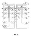
- FIG. 5is a simplified schematic view of the remote controller and the medical device exhibiting wireless communication
- FIG. 6is a flow chart illustrating screens for pairing a remote controller and medical device that may be displayed on the remote controller, in one exemplary embodiment
- FIG. 7is a flow chart illustrating screens for pairing a remote controller and medical device that may be displayed on the medical device in one exemplary embodiment
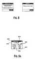
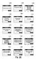
- FIG. 8illustrates notifications that may be displayed on the remote controller during the pairing process of a remote controller and medical device in one exemplary embodiment
- FIGS. 9A and 9Billustrate meter home screens that may be displayed on the remote controller in one exemplary embodiment
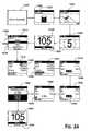
- FIG. 10illustrates a medical device home screen that may be displayed on the remote controller in one exemplary embodiment
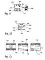
- FIG. 11illustrates a medical device home screen that may be displayed on the medical device in one exemplary embodiment
- FIG. 12illustrates a medical device setup screen that may be displayed on the medical device in one exemplary embodiment
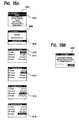
- FIG. 13illustrates RF communication setup and test screens that may be displayed on the remote controller in one exemplary embodiment
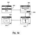
- FIG. 14illustrates RF communication setup screens that may be displayed on the remote controller in one exemplary embodiment
- FIG. 15illustrates RF communication setup screens that may be displayed on the medical device in one exemplary embodiment
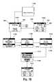
- FIGS. 16A and 16Billustrate bolus calculator setup screens that may be displayed on the remote controller in one exemplary embodiment
- FIG. 16Billustrates a series of display screens that can be used to provide various reports on glucose and insulin analysis
- FIG. 17illustrates RF communication on/off setup screens that may be displayed on the remote controller in one exemplary embodiment
- FIG. 18illustrates screens for turning RF communication on that may be displayed on the remote controller in one exemplary embodiment
- FIG. 19is a flow chart illustrating screens for unpairing a remote controller and medical device that may be displayed on the remote controller in one exemplary embodiment
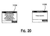
- FIG. 20illustrates notification screens that may be displayed on the remote controller during unpairing of a remote controller and medical device in one exemplary embodiment
- FIG. 21is a flow chart illustrating screens for a new pairing of a remote controller and medical device that may be displayed on the remote controller in one exemplary embodiment
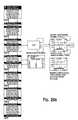
- FIG. 22is a flow chart illustrating screens for a new pairing of a remote controller and medical device that may be displayed on the medical device in one exemplary embodiment
- FIG. 23is a schematic flow chart that illustrates a method of establishing an acceptable time window for blood glucose results measured by a remote controller and relied upon in bolus calculations in one exemplary embodiment
- FIG. 24is a flow chart illustrating screens for calculating and delivering a bolus, that may be displayed on the remote controller in one exemplary embodiment
- FIG. 25illustrates a series of medical device and remote controller status screens that may be displayed on the remote controller in one exemplary embodiment
- FIG. 26illustrates a series of logbook and notification screens that may be displayed on the remote controller in one exemplary embodiment
- FIG. 27illustrates a series of medical device history screens that may be displayed on the remote controller in one exemplary embodiment
- FIG. 28illustrates a series of warning and notification screens that may be displayed on the remote controller, as used in the exemplary embodiments.
- FIG. 29illustrates a series of medical device warning screens that are similar in layout, and may be displayed simultaneously on both the remote controller and medical device, as used in the exemplary embodiments.
- Preferred embodiments described and illustrated hereinare directed generally to a system having a remote controller, which may wirelessly communicate with a medical device that dispenses a fluid or medication and various methods of operation.
- a remote controllerwhich may wirelessly communicate with a medical device that dispenses a fluid or medication and various methods of operation.
- the remote controller and the medical devicewirelessly communicate identification information with each other, how icons are used to notify a user that a wireless link that has been established between the remote controller and medical device, how similar user interfaces are used on both the remote controller and medical device, who multiple remote controllers can be paired with a medical device, how time windows are established for measured blood glucose values, and how device identification can be used with command histories.
- the terms “about” or “approximately” for any numerical values or rangesindicate a suitable dimensional tolerance that allows the part or collection of components to function for its intended purpose as described herein.
- the terms “patient”, “host” and “subject”refer to any human or animal subject and are not intended to limit the systems or methods to human use, although use of the subject invention in a human patient represents a preferred embodiment.
- the medical device 300is configured as an insulin infusion pump 300 , which, when placed in a wireless link with a specified remote controller 200 , can indicate identification information specific to the remote controller (as “Controller 1AB3DE” which is printed or affixed to the remote controller 200 ).
- the remote controller 200when placed in the wireless link with the infusion pump 300 , can indicate identification information specific to the infusion pump (as “Pump 123456” which is printed or affixed to the pump 300 ).
- a disease management systemcan be configured for a chronic disease such as diabetes
- the systemincludes a medical device, which has a display for the device and a remote controller.
- the remote controllerhas a controller display with the controller having controller identification information.
- the medical device displayis configured to display the controller identification information
- the controller displayis configured to display the medical device's identification information when the controller and medical device are linked to each other via a wireless link.
- a “link”is a bidirectional communication connection using radio waves, microwave, ultraviolet, infrared or combinations thereof.
- the controller displayincludes a first screen representative of analyte measurement information and a second screen representative of an infusion pump operational information.
- user indiciaindicates the graphical text, symbols, light or sounds and the particular arrangement of the text, symbols, light or sounds to define various functional screens (e.g., menus) to allow for programming and controlling of the controller 200 and pump 300
- user interfaceindicates the components such as buttons, switches or even a voice response interface in combination with the user indicia to allow for inputs or commands by the user.
- a methodis obtained in which the infusion pump and the remote controller are paired by exchanging identification information, which may include a serial number of the device; names; icons; avatars, speech identification, sounds, or combinations thereof. Also, where appropriate, the method allows for the pairing of additional remote controllers while unlinking or decoupling with any other previously paired remote controller.
- FIG. 2is a perspective view of a remote controller 200 for use in the exemplary embodiments.
- Remote controller 200includes a first housing 201 , a first display 202 , a first OK button 204 , a first down button 206 , back button 208 , a first up button 210 , light emitting diode (LED) 212 , and strip port connector (SPC) 214 .
- Remote controller 200is schematically shown in FIG.
- a first display (DIS) 202a first navigational buttons (NAV) 216 , a first radio frequency module (RF) 218 , a blood glucose measurement (BGM) module 220 , a first battery (BAT) 222 , a wired communication port (COM) 224 , a first alarm (AL) 226 , a first microprocessor (MP) 228 , a memory portion (MEM) 230 , and a memory chip port (MCP) 232 as shown in FIG. 5 .
- a first housing 201is ergonomically designed to be handheld and to incorporate the functional circuitry required for measuring glucose episodically and adapted to allow wireless communication with infusion pump 300 .
- the remote controller 200includes a port cover 209 .
- port cover 209is an elastomeric material that covers over a wired connection port 224 (not shown) and a memory chip port 232 (not shown).
- Examples of a wired connection portmay be a universal serial bus (USB) or IEEE RS 232.
- Examples of memory suitable for insertion into memory receiving portmay be a flash memory such as a SIMM card, a SmartCard, Smart Media, or any devices capable of storing data.
- first display 202may be a liquid crystal display (LCD) to show both textual and graphical information to a user.
- a user interfacemay be software driven menu that is shown on first display 202 that enables the user to operate remote controller 200 .
- a usercan navigate through the UI using first navigation buttons 216 which include first up button 210 , first down button 206 , first OK button 204 , and back button 208 .
- the UIallows a user to operate infusion pump 300 , query the status of infusion pump 300 , measure glucose episodically, and to display data on first display 202 from remote controller 200 and/or infusion pump 300 (e.g. glucose concentration versus time).
- First microprocessor 228may control first display 202 , first navigational buttons 216 , first RF module 218 , blood glucose measurement module 220 , wired communication port 224 , first alarm 226 , and memory chip port 232 .
- First microprocessor 228further provides the capability to perform various algorithms for the management of a medical treatment. Examples of such algorithms may include a predictive algorithm for a user's glucose concentrations (e.g. an algorithm that predicts a user's glucose concentration in the future) and a bolus calculator.
- a bolusis a pre-determined amount of a medication that is dispensed over a relatively short time period.
- first microprocessor 228may process inputs such as food data (e.g.
- carbohydrateswhich may be entered manually using first navigation buttons 216 , or via wired communication port 224 from a personal computer or like device.
- blood glucose datamay be provided to first microprocessor 228 directly from the blood glucose measurement module 220 .
- a bolus of insulincan be determined, and shown on first display 202 , and transmit the bolus amount wirelessly from remote controller 200 to infusion pump 300 . This enables infusion pump 300 to dose an appropriate amount of insulin to a user while at the same time reducing the amount of user interactions with infusion pump 300 .
- First RF module 218 on remote controller 200provides for bi-directional communication to infusion pump 300 and potentially other devices such as a continuous glucose monitor, a personal computer, a personal digital assistant, a cell phone, or a second infusion pump, which may dispense glucose.
- Exemplary frequencies that may be suitable for use with first RF module 218are about 433 MHz, about 863 MHz, about 903 MHz, and about 2.47 GHz.
- first RF module 218may include a commercially available component such as a Chipcon CC 1000, an antenna, and a RF impedance matching network.
- First RF module 218may send commands to infusion pump 300 such as a basal pump rate, duration of pump, and bolus amounts.
- first RF module 218may receive data from infusion pump 300 which includes an alarm indicating an occlusion or low insulin in reservoir, battery lifetime status, a continuous or semi-continuous glucose reading, and amount of remaining insulin in reservoir
- Wired communication port 224provides the option of transferring data to or from an external device such as a personal computer. Wired communication port 224 may also be used to upgrade the software memory portion 230 of remote controller 200 .
- Memory portion 230may be a volatile memory type such as for example flash memory.
- Memory portion 230may contain the application and system software for operating remote controller 200 .
- Wired communication port 224may then re-write memory portion 230 such that the entire application and system software is upgraded. This allows potential bugs in the software to be fixed and may be used to create added functionality in remote controller 200 .
- a flash memory cardmay be inserted into memory chip port 232 for upgrading remote controller 200 without connecting it to a personal computer.
- the flash memory cardmay also be used for adding language support, or supplying calibration information (e.g., for a CGMS device to be paired with the controller).
- Remote controllerincludes first alarm 226 which may be in a variety of forms to warn a user of various statuses that might need an actionable response.
- first alarm 226may include an audio alarm (monophonic beeps or polyphonic tones), a vibratory alarm, or a LED 212 which may be a multi-colored LED that can illuminate red, yellow, and green light.
- an alarm signalmy be used to warn a user that there is a low glucose reading, a partially filled glucose test strip, a low reservoir of insulin, an occlusion in infusion pump 300 , a low battery status for infusion pump 300 , a low battery status for remote controller 200 , and an improperly filled test strip.
- the alarmmay be a vibration, audio signal, and/or LED 212 switching from green to red or from green to yellow.
- FIG. 3is a perspective view of an infusion pump 300 for use in the exemplary embodiments.
- Infusion pump 300includes a second housing 301 , a backlight button 302 , a second up button 304 , a cartridge cap 306 , a bolus button 308 , a second down button 310 , a battery cap 312 , a second OK button 314 , and a second display 316 .
- Infusion pump 300may be suitable for use in dispensing medication such as insulin for improved diabetic therapies.
- second housing 301may include RF transparent material and may be painted with RF transparent paint. Referring to FIGS.
- infusion pump 300may further include second display (DIS) 316 , second navigational buttons (NAV) 318 , a reservoir (RES) 320 , an infrared communication port (IR) 321 , a second radio frequency module (RF) 322 , a second battery (BAT) 324 , a second alarm (AL) 326 , and a second microprocessor (MP) 328 .
- infusion pump 300 and remote controller 200may bi-directionally communicate using a wireless signal 400 via first RF module 218 and second RF module 322 .
- Reservoir 320typically contains insulin that can be dispensed from infusion pump 300 via tubing and a needle attached to a user. The tubing and needle may be attached to cartridge cap 306 .
- first RF module 218may be located within first housing 201 .
- second RF module 322may be located within second housing 301 .
- the material used for first housing 201 and second housing 301may be RF transparent (i.e. does not absorb or interfere with RF signals).
- first housing 201 or second housing 301require that it be painted, the paint used may be RF transparent as well.
- First RF module 218 and second RF module 322further include a communication protocol that enables remote controller 200 to communicate with only a particular infusion pump 300 .
- Both remote controller 200 and infusion pump 300have a unique identification code embedded in their respective first RF module 218 and second RF module 322 . This is desirable because under certain conditions, a second user with a second infusion pump 300 may be in close proximity to the first user. It would be undesirable for the first user's remote controller 200 to communicate with the second user's infusion pump 300 .
- a usermust initiate a pairing protocol before using infusion pump 300 for the first time.
- remote controller 200 and infusion pump 300exchange their unique identification code (e.g. serial number). In all subsequent wireless communications, the correct unique identification code must be established before exchanging data.
- remote controller 200may have an integrated blood glucose meter that can measure glucose episodically using disposable test strips.
- a test stripwhich may be suitable for use in the exemplary embodiments, is the commercially available OneTouch UltraTM test strip from LifeScanTM, Inc. in Milpitas, Calif., U.S.A.
- a test strip 100 suitable for use in remote controller 200is shown in FIG. 4
- remote controller 200can also wirelessly communicate with infusion pump 300 to provide information on the analyte measurements to the pump 300 .
- Remote controller 200can send commands to infusion pump 300 to dispense a fluid or medication for a pre-determined time period, rate, and/or volume.
- a usermay select from a menu of basal programs that have been programmed on infusion pump 300 .
- the usermay more specifically set a basal rate, a bolus dose, and a combination thereof may be programmed as commands to infusion pump 300 from remote controller 200 .
- Remote controller 200can receive data from infusion pump 300 such as the status of the dispensing of medication (e.g. the dispense rate, amount of medication remaining in infusion pump 300 , or the proportion of medication delivered based on the amount programmed).
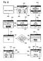
- FIG. 6is a flow chart illustrating screens for pairing a remote controller and infusion pump that may be displayed on the remote controller, as used in the exemplary embodiments.
- the first screenis splash screen 500 .
- Splash screen 500is displayed when 200 is turned on.
- the first screen displayed after splash screen 500is meter home screen 502 .
- Meter home screen 502typically includes last reading 506 , average reading 508 , time 510 , and battery icon 512 .
- Battery icon 512indicates the charge in first battery 222 . Pressing first OK button 204 while meter home screen 502 is displayed accesses main menu screen 516 .
- Meter settings 518can be highlighted by pressing first down button 206 . Pressing first OK button 204 results in meter settings screen 522 .
- RF 524can be highlighted by pressing first down button 206 , then selected by pressing first OK button 204 .
- RF setup screen 528is then displayed, and pairing 530 can be highlighted by pressing first down button 206 followed by first OK button 204 , resulting in the display of pairing screen 534 .
- Pairing screen 534instructs the user to activate the pairing mode on infusion pump 300 then to highlight and select start pairing command 538 . Once this is done, pairing status screen 542 is displayed, indicating pairing status 544 . In the process of pairing, units criteria 546 is checked.
- pairing result screen 550is then displayed.
- Paired infusion pump 552includes the serial number of the paired infusion pump. After verifying that paired infusion pump 552 is correct, accept command 554 is highlighted and selected.
- Remote infusion pump home screen 558is then displayed, and can be toggled with meter home screen 574 by pressing first down button 206 and first up button 210 .
- Remote infusion pump home screen 558includes infusion pump icon 560 , toggle icon 562 , signal strength icon 564 , battery icon 566 , time 568 , and delivery status 570 .
- Infusion pump icon 560indicates that remote infusion pump home screen 558 is a display screen that is associated with infusion pump 300 .
- Remote infusion pump home screen 558includes the serial number of the paired infusion pump, or alternatively can include a familiar name, assigned by the user to identify infusion pump 300 , instead of the infusion pump serial number.
- Toggle icon 562indicates that additional screens can be viewed by pressing first down button 206 or first up button 210 .
- Time 568displays the current time (a remote controller 200 setting).
- Signal strength icon 564indicates RF signal strength between remote controller 200 and infusion pump 300 .
- Battery icon 566indicates that infusion pump 300 has a full battery charge.
- Delivery status 570is an infusion pump status indicating active basal dosing and that infusion pump 300 contains 100 units of insulin.
- Remote infusion pump home screen 558can be toggled with meter home screen 574 using first down button 206 and first up button 210 .
- Meter home screen 574includes meter icon 576 , indicating that meter home screen 574 is a display screen related to remote controller 200 .
- Meter home screen 574includes toggle icon 578 , signal strength icon 580 , and battery icon 582 .
- Toggle icon 578indicates that additional screens can be viewed by pressing first down button 206 and first up button 210 .
- Signal strength icon 580indicates RF signal strength between remote controller 200 and infusion pump 300 .
- Battery icon 582indicates the battery charge in remote controller 200 .
- FIG. 7is a flow chart illustrating screens for pairing a remote controller and infusion pump that may be displayed on the infusion pump, as used in the exemplary embodiments.
- local infusion pump home screen 600When infusion pump 300 is turned on, local infusion pump home screen 600 is displayed.
- Local infusion pump home screen 600includes time 602 , battery icon 604 , delivery status 606 , status command 608 , and 610 .
- Time 602is the time set in infusion pump 300 . This time must match the time set in remote controller 200 , and displayed as time 510 in FIG. 6 .
- Battery icon 604indicates the battery charge in infusion pump 300 .
- Delivery status 606indicates the current delivery status of infusion pump 300
- status command 608 and 610are sub-menu items related to infusion pump status and the main menu of infusion pump 300 .
- Second OK button 314is pressed and main menu screen 612 is displayed.
- Second down button 310can be used to highlight setup 614
- second OK button 314is pressed to display setup screen 615 .
- remote setup screen 618is displayed.
- RF 620can be switched to on using second up button 304 , second down button 310 , and second OK button 314 . When RF 620 is on, channel 622 is set to AUTO mode.
- remote setup screen 624In AUTO mode the channel for RF communication is selected automatically.
- search 626is toggled to ON, and then remote setup screen 628 is displayed.
- Remote setup screen 628includes search status 630 .
- Search status 630indicates that second RF module 322 is searching for compatible RF signal from other devices, such as first RF module 218 .
- remote setup screen 634is displayed, the channel over which RF communication occurs is displayed in channel 638 , and the user is prompted to confirm paired remote 640 using confirm 642 .
- remote setup screen 644is displayed.
- Remote setup screen 644includes paired remote 646 and next 648 .
- display 316displays local infusion pump home screen 650 . Since infusion pump 300 is now paired with remote controller 200 , remote control icon 652 is displayed. When remote control icon 652 is displayed, it indicates that RF is enabled, infusion pump 300 is paired with remote controller 200 , and that infusion pump 300 is ready to receive commands from remote controller 200 . Remote control icon 652 does not indicate RF traffic/activity, signal strength, or health of communications. It simply means that infusion pump 300 is enabled to receive RF commands from remote controller 200 . If remote control icon 652 is not displayed on local infusion pump home screen 650 it means that RF communication between remote controller 200 and infusion pump 300 is disabled, and that infusion pump 300 will not receive commands from remote controller 200 .
- FIG. 8illustrates notifications that may be displayed on remote controller 200 during the pairing process of remote controller 200 and infusion pump 300 , as used in the exemplary embodiments. Since it is important that the units of measure are the same in both bolus calculations and in historical data logs, the pairing feature will fail if the units are not identical. In some embodiments, the units can be changed by the user in both remote controller 200 and infusion pump 300 . In other embodiments the units are fixed at the factory and can't be changed, in which case either remote controller 200 or infusion pump 300 are exchanged for models with compatible units of measure. In addition to units of measure, it is also important that remote controller 200 and infusion pump 300 are set to the same time. This is important in establishing when blood glucose tests were performed, and in logging events such as bolus and basal delivery. Accurate time settings are also important in monitoring averages at different times of the day.
- the remote controller 200 and the infusion pump 300may incorporate a suitable radio frequency communication system, such as, for example, a far-field radio frequency communication element (“RF”) for bi-directional communication.
- the center frequenciescan be any suitable frequencies. In the preferred embodiments, the center frequencies are approximately 868 MegaHertz (“MHz”) and approximately 903 MHz.
- the systempreferably uses the ChipconTM Product CC1100 RF Transceiver supporting frequency modulated and Frequency Shifting Keying for data transfer. Manchester encoding can be utilized to allow for self-clocking as the clock is embedded in the signal. Alternatively, Non-Return-to-Zero or NRZ encoding can also be utilized.
- the RF elementutilizes a communication protocol that has a learn mode or “pairing” mode which pairs the two devices (remote controller 200 and infusion pump 300 ), in which the unique identification code of each communicating device is exchanged.
- Device “pairing”is a process in which a master (remote controller 200 ) learns who its slave is (an infusion pump) and in which the slave (infusion pump) learns who its master (remote controller) is. All devices utilize suitable information identification, such as, for example, a fixed device-type serial number address, sound, or optical identifier.
- the remote controller 200holds one serial number of the infusion pump 300 that is paired with the controller 200 ; the infusion pump 300 stores one single master remote controller's serial number from which it will accept commands; and only one remote controller 200 and one infusion pump 300 may be paired at a time. If a new remote controller 200 is to be “paired” to an infusion pump 300 , the other remote controller 200 is “un-paired” or whose communication is ignored.
- a communications “channel”is established for the system.
- the “channel”is preferably a frequency offset from the center frequency. The use of channels is believed to provide for communication that is more robust.
- the RF communicationcan be initiated by either the infusion pump 300 or the controller 200 .
- the communicationis initiated by the remote controller 200 (master). There is a predefined wait-listen period after the remote controller 200 transmits to the infusion pump 300 , where the remote controller 200 listens for a response from the infusion pump 300 .
- the infusion pump 300indicates its state, if it is busy or can communicate with the remote controller 200 .
- the remote controller 200will then communicate with the infusion pump 300 to ask for the status (alarm, alerts, insulin units delivered, etc.) of the infusion pump, and the infusion pump will send and receive data upon request to and from the remote controller 200 .
- the RF transmissioncan utilize a single frame of transmission.
- a framecan include a plurality of preamble or synchronization information, header and data.
- the frameincludes preamble and synchronization information, a frame header and an optional data packet with cyclic-redundancy-checksum (“CRC”).
- CRCcyclic-redundancy-checksum
- three preamble lengthsmay be utilized: (1) a long; (2) medium; and (3) short preambles.
- the long preambleis used for initiating communication
- the medium preambleis used for automatic session initiation and a short preamble is used once communication is established.
- the predetermined number of preamble bytes to be transmittedwill vary within a certain range instead of a fixed number of preamble bytes.
- the preamble bytesare sent before the frame to allow the RF receiver to lock and receive the frame.
- the variationis caused by the clock jitter of the timer, which may cause the preamble periods to be decreased or increased by about 25 milliseconds.
- the short and long preamble periodsmay be configured to account for the shortest possible variations in preamble period that could occur because of clock jitter.
- the buffer time periodmay be configured to have about the same magnitude as the clock jitter in the transmitting device.
- the preamble periodmay be about greater than or equal to the time periods for the high frequency power saving mode or the low frequency power saving mode of the receiving device. Consequently, a transmitting device may reliably and robustly send a sufficiently long preamble that will be properly received by the receiving device even if the transmitting device sends the lowest possible preamble length due to clock jitter.
- the listening window schemeuses a two-stage sniff interval to optimize communication on-times.
- the frame headerincludes a command, frame number, size of the optional data packet and a CRC for the frame header.
- the communication protocolalso incorporates a mechanism to insure that the data has been transmitted correctly by validating and verifying the transmission, this includes a use of a cyclical redundancy check and acknowledgment in the communication.
- the associated data packetmay contain the 1's complement of another data field as an added safety check for the receiver. Further, the receiver may respond to the command by repeating data fields of the initial data packet as a safety check for the originating transmitter.
- FIGS. 9A and 9Billustrate meter home screens that may be displayed on remote controller 200 , as used in the exemplary embodiments.
- FIG. 9Aillustrates meter home screen 504 , a typical display before pairing
- FIG. 9Billustrates meter home screen 574 , a typical display after pairing.
- meter home screen 504Before pairing, meter home screen 504 includes meter icon 576 , time 510 , battery icon 582 , last reading 506 , and meter home screen 502 .
- Meter icon 576indicates that the screen is related to remote controller activities.
- Time 510is the current time, as set in remote controller 200 .
- Battery icon 582indicates remaining power in remote controller 200 , and can vary between empty, low, medium, and full.
- meter home screen 574includes toggle icon 578 , signal strength icon 580 , and keys locked icon 584 .
- Toggle icon 578indicates that the user can switch between meter home screen 574 and remote infusion pump home screen 558 (described in reference to FIG. 10 ), by toggling first down button 206 and first up button 210 .
- Signal strength icon 580indicates the status of RF communication between remote controller 200 and infusion pump 300 , and varies between RF off icon 585 , RF down icon 588 , low RF strength icon 590 , medium RF strength icon 592 , and full RF strength icon 594 . If no infusion pump is paired, signal strength icon 580 is not shown.
- Keys locked icon 584indicates that the user interface has been locked, and only limited functionality is available, preventing inadvertent activation of controller and infusion pump functions.
- FIG. 10illustrates an infusion pump home screen that may be displayed on remote controller 200 , as used in the exemplary embodiments.
- Remote infusion pump home screen 558is only displayed on remote controller 200 if remote controller 200 is paired to infusion pump 300 .
- the usercan toggle between remote infusion pump home screen 558 and meter home screen 574 (illustrated in FIG. 9B ) by pressing first down button 206 or first up button 210 on remote controller 200 .
- Remote infusion pump home screen 558includes remote infusion pump home screen 586 , indicating the serial number or friendly name of infusion pump 300 with which remote controller 200 is paired.
- remote infusion pump home screen 586includes the serial number of infusion pump 300 with which remote controller 200 is paired.
- the serial number displayed on remote infusion pump home screen 586can be checked against the serial number printed on the back of infusion pump 300 .
- the identifying information in infusion pump 300can be programmed to display a more common name in remote infusion pump home screen 586 such as “Harold's infusion pump.”
- the common name displayed on remote infusion pump home screen 586can include a common name only, a common name along with a serial number, or only the serial number, as in the preferred embodiments. This makes it easier for a user to confirm correct pairing between remote controller 200 and infusion pump 300 .
- identifierscan be used to help the user in confirmation of correct pairing.
- Those embodimentscan included user programmed computer icons, computer avatars, names, sounds, or pictures.
- user programmed computer icons, computer avatars, names, sounds, or picturescan be displayed, indicating to the user correct pairing between remote controller 200 and infusion pump 300 .
- the identifying information in infusion pump 300can be entered directly into infusion pump 300 by way of its keyboard, or it can be downloaded from a personal computer. Identifying information can also be added to remote controller 200 , and can be displayed whenever remote controller 200 is turned on and remote controller related screens are displayed, such as meter home screen 574 .
- Remote infusion pump home screen 558also includes infusion pump icon 560 , toggle icon 562 , signal strength icon 564 , battery icon 566 , time 568 , and delivery status 570 .
- Infusion pump icon 560is an icon that indicates to the user that they are viewing an infusion pump related screen.
- Toggle icon 562indicates to the user that they can switch between remote infusion pump home screen 558 and meter home screen 574 (illustrated in FIG. 9B ) by pressing first down button 206 or first up button 210 .
- Signal strength icon 564indicates the status of RF communication between remote controller 200 and infusion pump 300 , as described previously in respect to signal strength icon 580 (in FIG. 9B ).
- Battery icon 566indicates remaining power in infusion pump 300 , and can vary between empty, low, medium, and full. If battery icon 566 indicates no remaining power in infusion pump 300 , no functions are available in infusion pump 300 , and an alarm screen appears.
- Time 568is the current time, as entered in remote controller 200 and infusion pump 300 .
- Delivery status 570indicates the delivery status of infusion pump 300 , and the remaining insulin in infusion pump 300 .
- FIG. 11illustrates an infusion pump home screen that may be displayed on the infusion pump 300 , as used in the exemplary embodiments.
- Local infusion pump home screen 600differs from remote infusion pump home screen 558 (illustrated in FIG. 10 ) in that local infusion pump home screen 600 is displayed on infusion pump 300 , while remote infusion pump home screen 558 is displayed on remote controller 200 .
- remote controller 200In systems that include both remote controller 200 and infusion pump 300 , and where commands entered on remote controller 200 can control infusion pump 300 , it is desirable to have user interface screens on both remote controller 200 and infusion pump 300 which allow manipulation and control of features on infusion pump 300 , such as basal delivery, bolus delivery, infusion pump status, and infusion pump history.
- local infusion pump home screen 600can include identifying information, such as the serial number of infusion pump 300 , or a friendly name or recognizable name, such as “Harold's infusion pump.” Identifying information can help in assuring to a user that they are using the correct infusion pump 300 .
- local infusion pump home screen 600includes time 602 , battery icon 604 , delivery status 606 , status command 608 , 610 , and remote control icon 652 .
- Battery icon 604indicates remaining power in infusion pump 300 , and can vary between empty, low, medium, and full. If battery icon 604 is empty, no functions are available on infusion pump 300 , and an alarm screen appears.
- Battery icon 604 on local infusion pump home screen 600is similar in function and appearance to battery icon 566 on remote infusion pump home screen 558 , maintaining consistency in the user interface of remote controller 200 and infusion pump 300 .
- Time 602displays the current time, as entered in the setup of infusion pump 300 . It is similar in appearance and function to time 568 on remote infusion pump home screen 558 .
- Delivery status 606indicates the current delivery mode and remaining insulin in infusion pump 300 .
- Delivery status 606is similar in appearance and function to delivery status 570 on remote infusion pump home screen 558 .
- Status command 608is a submenu, and allows access to a series of infusion pump status screens.
- 610is a submenu that allows access to the infusion pump main menu.
- Remote control icon 652is an icon that indicates the infusion pump is under remote control. When remote control icon 652 is displayed, RF communication between remote controller 200 and infusion pump 300 is enabled, remote controller 200 and infusion pump 300 have been paired, and infusion pump 300 is ready to receive remotely entered commands from remote controller 200 .
- this icondoes not indicate RF traffic/activity, signal strength, or health of communications, as other icons do (such as signal strength icon 564 in FIG. 10 , signal strength icon 580 in FIG. 9B , which have been described previously).
- remote control icon 652can include indication as to RF traffic/activity, signal strength, or health of communications, or one can also include an icon such as signal strength icon 564 or signal strength icon 580 near remote control icon 652 .
- FIG. 12illustrates an infusion pump setup screen that may be displayed on infusion pump 300 , as used in the exemplary embodiments.
- Remote setup screen 634includes RF 620 , search 636 , channel 638 , paired remote 640 , confirm 642 , next 648 , and home 654 .
- RF 620allows a user to enable or disable RF communication between infusion pump 300 and remote controller 200 . When RF 620 is toggled to on, RF communication between infusion pump 300 and remote controller 200 is enabled. When RF 620 is toggled to off, RF communication between infusion pump 300 and remote controller 200 is disabled.
- infusion pump 300is currently paired with remote controller 200 when RF 620 is toggled to off, pairing data is preserved so it can be restored when RF is re-enabled. If remote controller 200 is currently attempting to pair when RF 620 is toggled to off, the pairing attempt is aborted, and previous pairing data is restored, if available.
- RF 620is toggled to “ON” and infusion pump 300 was previously paired to remote controller 200
- infusion pump 300automatically begins pairing to the previously paired remote controller 200 . If infusion pump 300 was not previously paired to remote controller 200 , infusion pump 300 prepares itself to be paired for the first time. Search 636 is used to initiate pairing between infusion pump 300 and remote controller 200 .
- infusion pump 300When search 636 is blank, infusion pump 300 is not paired with remote controller 200 , and it does not contain pairing data. This is the state of infusion pump 300 when it is turned on for the first time. Unlike remote controller 200 , once infusion pump 300 is paired, there is no means to un-pair it.
- search 636When search 636 is “ON”, pairing between infusion pump 300 and remote controller 200 has begun, and is in process.
- search 636is “DONE”, the pairing search between infusion pump 300 and remote controller 200 has ended, as a result of successful pairing, or as a result of aborted pairing.
- Channel 638indicates the method for selecting the channel over which RF communication between infusion pump 300 and remote controller 200 will occur. When set to “AUTO”, the software in infusion pump 300 determines the RF channel.
- Paired remote 640displays the pairing status between infusion pump 300 and remote controller 200 .
- paired remote 640is blank, infusion pump 300 is not paired with remote controller 200 .
- paired remote 640displays “searching”, infusion pump 300 is attempting to pair with remote controller 200 .
- the deviceprovides confirmation such as, for example, a series of tone, a display or other visual indicators.
- the paired remote 640displays the serial number or other identifying information (such as a name, computer icon, sounds or series of tones/vibrations, etc.) of the device, this allows the user to easily check that they have paired with the appropriate device, particularly if the identifying information is familiar, such as “Bob's remote Controller”. If paired remote 640 displays the serial number of the paired device, such as remote controller 200 , it can be checked against the serial number printed on the back of the paired device. Confirm 642 is a command that allows the user to confirm RF connection between infusion pump 300 and a paired device, such as remote controller 200 .
- confirm 642displays a cancel command, in case the user wants to cancel the pairing search. If confirm 642 displays a confirm command, and it is not executed by the user, the pairing between infusion pump 300 and remote controller 200 is rejected. This allows a user to reject pairing with the wrong device, such as someone else's infusion pump.
- FIG. 13illustrates RF communication setup and test screens that may be displayed on the remote controller 200 , as used in the exemplary embodiments.
- RF set up screen 700is displayed on remote controller 200 , and is a remote controller related screen, as indicated by meter icon 576 .
- RF test screen 704is displayed.
- RF test screen 704includes identification 706 , RF channel 708 , and start 710 .
- Identification 706identifies the infusion pump 300 with which remote controller 200 is paired, and can be in the form of a serial number, a name, or other identifying feature, as mentioned previously.
- RF channel 708identifies the RF channel over which remote controller 200 communicates with infusion pump 300 , and was selected either automatically by remote controller 200 and infusion pump 300 during pairing, or was selected for optimum signal and reception by the user.
- Start 710is a command that initiates the start of an RF test.
- RF test screen 712displays the result of the test, and includes RF channel 714 , RF signal 716 , and RF quality 718 .
- RF channel 714identifies the channel over which RF communication occurs between remote controller 200 and infusion pump 300
- RF signal 716identifies the strength of the RF signal
- RF quality 718identifies the quality of the RF signal.
- An RF testis useful in identifying paired infusion pumps infusion pump 300 , and in troubleshooting the RF communication between remote controller 200 and infusion pump 300 .
- the RF testcan also be helpful in displaying pairing specifics to the user.
- FIGS. 14 and 15illustrate RF communication setup screens that may be displayed on remote controller 200 and infusion pump 300 , as used in the exemplary embodiments.
- FIG. 14illustrates RF setup screen 800 , which is displayed on remote controller 200 .
- RF channel 802is highlighted and selected, RF channel selection screens are displayed.
- notification 804the user is notified that the same RF channel should be used on both remote controller 200 and infusion pump 300 , and must confirm the notification using confirm 806 .
- either RF channel screen 808 or RF channel screen 812is displayed, with toggle icon 810 indicating that RF channel screen 808 can be toggled through several channels, or can be toggled to RF channel screen 812 for automatic RF channel selection.
- FIG. 25illustrates a series of user interface screens that are displayed on infusion pump 300 and allow a user to either automatically select an RF channel, or to specify an RF channel manually.
- the current RF channelis highlighted, as illustrated by channel 816 .
- second up button 304 and/or second down button 310a different channel number can be selected, as illustrated by channel 820 in remote setup screen 818 , or the channel selection can be set to automatic.
- second OK button 314is pressed to program infusion pump 300 to that channel, and remote setup screen 822 is displayed.
- FIGS. 16A and 16Billustrate bolus calculator setup screens that may be displayed on the remote controller, as used in the exemplary embodiments.
- the screens illustrated in FIG. 16Aare used when remote controller 200 is not paired with infusion pump 300 .
- calculator settingsare automatically copied from infusion pump 300 to remote controller 200 .
- notification 900is displayed to the user on remote controller 200 , reminding the user that values stored in remote controller 200 will be overwritten with those stored in infusion pump 300 when pairing between remote controller 200 and infusion pump 300 is confirmed by the user.
- bolus calculationscan be performed by remote controller 200 using calculator settings entered by the screens illustrated in FIG. 16A .
- main menu screen 902bolus 904 is highlighted and selected, leading to customize screen 906 .
- customize screen 906calculator setup 908 is highlighted and selected, leading to calculator setup screen 910 .
- various bolus calculator settingscan be made, including I:C Ratio 912 , BG Target 916 , BG Delta xxx and IS Factor 918 .
- I:C Ratio 912 , BG Target 916 , BG Delta xxx and IS Factor 918are used in calculating various types of bolus delivery, including those that will compensate for carbohydrate intake and those that will return blood glucose values to desired levels.
- I:C Ratio 912is used to set an insulin to carbohydrate ratio, and is used in calculating a bolus that will compensate for ingestion of carbohydrates from a meal or snack. It is defined as the approximate number of grams of carbohydrates that can be compensated with one unit of insulin.
- BG Target 916allows the user to enter a target blood glucose value. Target blood glucose values are used when maintaining good glycemic control.
- BG Delta xxxallows the user to enter a value that is added to and subtracted from the BG Target 916 in order to define an acceptable range of blood glucose values for the user. If the user's current blood glucose reading is within the range then the meter will not adjust its insulin recommendation to compensate for the blood glucose reading being above or below BG Target 916 .
- bolus delivery recommendationsIn a normal delivery, the entire insulin bolus is delivered all at once. With a combo bolus delivery, the user can select a percentage of the infusion to deliver at once, termed the “normal” portion, with the remaining percentage, termed the “extended” portion, delivered over an extended period of time as set by the user. The user can select the initial delivery amount from 0% to 100% thereby allowing an all extended delivery and all normal delivery respectively.
- a BG combo deliveryworks like the combo bolus delivery except that the insulin needed for BG correction is added to the normal portion of the delivery.
- Each of the devicespreferably uses two calculations to provide for the recommended bolus delivery: “ezBG” and “CarbSmart.”
- the ezBG computationdoes not account for carbohydrates while the CarbSmart calculation includes carbohydrates.
- the microprocessor of either the remote controller or the infusion pumpcan perform the ezBG bolus computation.
- BGCarbSmart Bolus Total as a normal, combo or BG combo delivery.
- Combo deliveriesallow the user to specify a percentage of the bolus for immediate delivery with the remainder delivered within the user specified duration.
- the BGcan be calculated by the remote controller 200 using blood glucose measurement data stored or obtained in the remote controller 200 and transmitted to the device 300 .
- FIGS. 17 and 18illustrate screens for turning RF communications on and off, and may be displayed on remote controller 200 , as used in the exemplary embodiments.
- RF setup screen RF setup screen 1000allows the user to select from among several RF setup options. By highlighting and selecting RF on/off 1002 a user can toggle RF communication on and off. In RF on/off screen 1004 , the user is warned that communication between remote controller 200 and infusion pump 300 will stop when RF is turned off, and is prompted to continue turning RF off, or to cancel the command.
- RF on/off screen 1008 and RF on 1010 of FIG. 28the user will be warned that communication between paired devices will be reestablished if RF is turned on, as illustrated in RF on/off screen 1008 and RF on 1010 of FIG. 28 .
- RF on/off screen 1012is displayed, indicating that RF communication is being reestablished with the previously paired device connection status 1016 .
- RF on/off screen 1014 and connection status 1018is indicated to the user by RF on/off screen 1014 and connection status 1018 .
- FIG. 19is a flow chart illustrating screens for unpairing a remote controller and infusion pump that may be displayed on the remote controller, as used in the exemplary embodiments.
- remote controller 200When remote controller 200 is turned on, it displays splash screen 1100 , followed by remote infusion pump home screen 1102 .
- Remote infusion pump home screen 1102is displayed because remote controller 200 is paired with infusion pump 300 .
- Remote infusion pump home screen 1102includes infusion pump icon 560 , toggle icon 562 , signal strength icon 564 , and battery icon 566 , as described previously.
- Infusion pump icon 560indicates that remote infusion pump home screen 1102 is related to infusion pump 300 functions
- toggle icon 562indicates that remote infusion pump home screen 1102 can be toggled with meter home screen 1104 by pressing first down button 206 and first up button 210 .
- Meter home screen 1104includes meter icon 576 , toggle icon 578 , and signal strength icon 580 .
- Meter icon 576indicates that meter home screen 1104 is related to remote controller 200 functions, while toggle icon 578 and signal strength icon 580 function as described previously.
- main menu screen 1106By pressing first OK button 204 while remote infusion pump home screen 1102 or meter home screen 1104 is displayed, main menu screen 1106 will be displayed. Highlighting and selecting meter settings 1116 causes meter settings screen 1108 to be displayed.
- Highlighting and selecting RF 1118causes RF setup screen 1110 to be displayed, while highlighting and selecting pairing 1120 leads to pairing screen 1112 .
- Pairing screen 1112notifies the user that remote controller 200 is paired with infusion pump 300 (identified by serial number, or other identifying information as described previously), and allows the user to confirm unpairing by selecting unpairing 1122 .
- meter home screen 1114is displayed, without toggle icon 578 and signal strength icon 580 , as were seen in meter home screen 1104 .
- Toggle icon 578 and signal strength icon 580are not displayed in meter home screen 1114 because remote controller 200 is no longer paired with infusion pump 300 , remote infusion pump home screen 1102 is no longer an option for display, and RF is deactivated.
- various warning and notification screenscan be displayed, such as notification 1124 and notification 1126 , illustrated in FIG. 30 .
- FIG. 21is a flow chart illustrating screens for a new pairing of remote controller 200 and infusion pump 300 that may be displayed on remote controller 200 , as used in the exemplary embodiments.
- remote controller 200When remote controller 200 is turned on, it displays splash screen 1200 , followed by remote infusion pump home screen 1202 .
- Remote infusion pump home screen 1202is displayed because remote controller 200 is paired with infusion pump 300 .
- Remote infusion pump home screen 1202includes infusion pump icon 560 , toggle icon 562 , signal strength icon 564 , and battery icon 566 , as described previously.
- Infusion pump icon 560indicates that remote infusion pump home screen 1202 is related to infusion pump 300 functions
- toggle icon 562indicates that remote infusion pump home screen 1202 can be toggled with meter home screen 1204 by pressing first down button 206 and first up button 210 .
- Meter home screen 1204includes meter icon 576 , toggle icon 578 , and signal strength icon 580 .
- Meter icon 576indicates that meter home screen 1204 is related to remote controller 200 functions, while toggle icon 578 and signal strength icon 580 function as described previously.
- main menu screen 1206By pressing first OK button 204 while remote infusion pump home screen 1202 or meter home screen 1204 is displayed, main menu screen 1206 will be displayed. Highlighting and selecting meter settings 1216 causes meter settings screen 1208 to be displayed.
- Pairing screen 1212notifies the user that remote controller 200 is paired with infusion pump 300 (identified by serial number, or other identifying information as described previously), and allows the user to confirm new pairing by selecting new pairing 1222 .
- pairing screen 1214is displayed, instructing the user to activate pairing mode on infusion pump 300 , and to select start pairing 1234 .
- Pairing screen 1224is then displayed, indicating that remote controller 200 is searching for a new infusion pump 300 .
- One parameter that is checked during the pairing searchis that remote controller 200 and infusion pump 300 have the same glucose units of measure, as mentioned previously.
- remote controller 200 and infusion pump 300do not have the same glucose units of measure, the new pairing process is aborted. Assuming that the same units of measure are found, pairing screen 1228 is then displayed, indicating that a new infusion pump 300 has been found, and including identification 1236 and any other identifying information, as described previously. After accepting the pairing, remote infusion pump home screen 1230 is displayed. Remote infusion pump home screen 1230 includes identifying information for new infusion pump 300 , and can be toggled with meter home screen 1232 using first down button 206 and first up button 210 .
- FIG. 22is a flow chart illustrating screens for a new pairing of remote controller 200 and infusion pump 300 that may be displayed on the infusion pump, as used in the exemplary embodiments.
- local infusion pump home screen 600is displayed.
- Local infusion pump home screen 600includes time 602 , battery icon 604 , delivery status 606 , status command 608 , and menu command 610 , described previously in reference to FIG. 7 .
- second OK button 314is pressed and main menu screen 612 is displayed.
- Second up button 304 and second down button 310can be used to highlight setup 614 and second OK button 314 is pressed to display setup screen 615 .
- remote setup screen 1300After highlighting and selecting advanced 616 , remote setup screen 1300 is displayed.
- Remote setup screen 1300includes RF 1302 , search 1304 , channel 1306 , and identification 1308 . Since infusion pump 300 is already paired to a remote controller 200 , RF 1302 is ON, search 1304 indicates DONE, and channel 1306 is set to a channel over which RF communication between remote controller 200 and infusion pump 300 occurs.
- Identification 1308displays identifying information as to the paired remote controller 200 .
- search 1312has been switched to ON, initiating a new pairing search.
- Remote setup screen 1314displays the ongoing search status, where channel 1316 has automatically been set to AUTO since a new search is under way, and search status 1318 indicates that infusion pump 300 is searching for a new remote controller 200 .
- remote setup screen 1320is displayed.
- Channel 1322is set to the new channel for RF communication that was automatically set by 328
- identification 1324displays new identifying information for remote controller 200 .
- Confirm 1326prompts the user to confirm pairing with new remote controller 200 .
- remote setup screen 1328is displayed. Selecting next 1330 completes the new pairing process, and returns the display to local infusion pump home screen 1332 .
- multiple remote controllers 200can be paired with a single infusion pump 300 . This allows a user to have backup remote controllers 200 , or allows them to keep remote controllers 200 in multiple locations, such as at home and at the office. Each remote controller 200 must initially be paired with infusion pump 300 to exchange identifying information. An RF detection algorithm in infusion pump 300 determines if it is possible to transfer remote control from one remote controller 200 to another. In addition, an acknowledgment from the user is required when switching remote control from one remote controller to another. As mentioned previously, each remote controller 200 must be initially paired with infusion pump 300 . Pairing information for each remote controller 200 is stored in non-volatile memory within infusion pump 300 . Pairing information can be stored for several remote controllers 200 .
- Pairing informationmay include an RF address which is unique and assigned by the device manufacturer, an RF type which identifies the type of device being paired, a default channel which specifies the channel over which communication will occur the next time communications are established, flags that include additional information such as hardware/software revision levels and units of measure, and serial numbers that uniquely identify each remote controller 200 .
- An algorithm in infusion pump 300determines when remote controller 200 may be changed. While 200 and 300 are paired, and are in RF communication with each other, they routinely communicate. For instance, on a regular interval, remote controller 200 requests the status of 300 by way of RF communication.
- infusion pump 300does not communicate with the currently paired remote controller 200 within a fixed time, it will start to search for previously paired, and memorized, remote controllers 200 . For efficiency, the search starts with the most recently paired remote controller 200 . The dwell time spent searching for each previously paired controller is based on the minimum system RF sniff time. Once a previously paired remote controller 200 is found, the user is prompted to acknowledge transfer of remote control to the previously paired remote controller 200 .
- An advantage of this embodimentis that it is easier for the user to switch between previously paired devices.
- FIG. 23is a schematic flow chart that illustrates a method of establishing an acceptable time window for blood glucose results measured by a remote controller and relied upon in bolus calculations, as used in the exemplary embodiments.
- the method illustrated in FIG. 23can be used in remote controller 200 or in infusion pump 300 .
- the processbegins by in initiating step 1400 .
- Step 1400can be initiated immediately after measuring blood glucose with remote controller 200 , or can be initiated after measuring blood glucose with a separate blood glucose meter.
- Step 1400can be initiated whenever the user would like to deliver a bolus.
- memory in remote controller 200 or infusion pump 300is checked for recent blood glucose measurements. In a particularly preferred embodiment, recent blood glucose measurements are those taken within the last 15 minutes.
- a blood glucose measurementwas taken within the last 15 minutes, it is automatically entered into the bolus calculator, as illustrated in step 1404 .
- a recommended bolusis calculated, as illustrated in step 1406 .
- the bolus calculationis done, as illustrated by step 1408 , and the user has the choice of making adjustments to or delivering the recommended bolus.
- BG resultsare only entered on the pump 300 when a bolus calculation is done on the pump 300 . That result must be manually entered by the user into the pump 300 . Such result stored in pump 300 is then transferred to the memory of controller 200 during the next communication interval.
- the useris prompted to retest their blood glucose, as illustrated in step 1410 . If they choose to retest using remote controller 200 , they return to step 1400 of the process, and the result is automatically transferred to the bolus calculator as in step 1404 . If they choose not to retest, or if they retest using a separate blood glucose meter, the user can manually enter a blood glucose result, as illustrated in step 1414 . As soon as the user manually enters a blood glucose value, the blood glucose calculator determines a recommended bolus, as in step 1406 , and the user has the choice to adjust or deliver the recommended bolus.
- FIG. 24is a flow chart illustrating screens for calculating and delivering a bolus, that may be displayed on remote controller 200 , as used in the exemplary embodiments.
- splash screen 1500is displayed, followed by test screen 1502 .
- Test screen 1502includes meter icon 1528 , indicating that it is a display screen related to remote controller functions.
- Test screen 1502indicates to the user that they should check that the lot code on their test strips matches the lot code entered in remote controller 200 . The user is then prompted to apply blood to the test strip, after which test screen 1506 appears, counting down to a result.
- the blood glucose concentrationis displayed using result screen 1508 .
- Bolus menu screen 1510includes infusion pump icon 1532 , identification 1534 , and ezBG 1536 .
- Infusion pump icon 1532indicates that bolus menu screen 1510 is related to infusion pump functions
- identification 1534includes identifying information (such as infusion pump serial number or a familiar name)
- ezBG 1536accesses a bolus calculator that allows correction for high blood glucose concentrations.
- ezBG calculator screen 1512is displayed. As long as a blood glucose reading has been made with remote controller 200 within the last 15 minutes, actual BG 1538 includes a value for actual blood glucose.
- ezBG calculator screen 1514is displayed.
- ezBG total screen 1516includes recommended bolus 1540 , a recommended bolus amount that is based upon the data entered in ezBG calculator screen 1514 .
- screen ezBG total screen 1518the user has an option to enter the recommended bolus amount 1540 , or they can alter the user-entered bolus 1542 .
- ezBG total screen 1520is displayed.
- bolus deliverybegins, as indicated in bolus screen 1522 . Initiation of bolus delivery can be accompanied by visual or audio clues, such as beeps, tunes, or flashing lights.
- result screen 1524is displayed, where users can enter comments or return to home screens, as desired.
- FIG. 24illustrates the use of a bolus calculator in respect to blood glucose correction boluses, a similar approach can be used when using bolus calculators to determine a bolus amount to compensate for carbohydrate intake. In cases where the bolus is used to compensate for carbohydrate intake, additional parameters are entered by the user, such as recent carbohydrate intake.
- FIGS. 25 , 26 A, and 27illustrate a series of screens displayed on remote controller 200 that relate to the status of infusion pump 300 , the status of remote controller 200 , the logbook of remote controller 200 , and the history of infusion pump 300 , as used in the exemplary embodiments.
- main menu screen 1600includes submenu item system status 1620 .
- system status screen 1602is displayed.
- Selecting infusion pump status 1622results in display of active basal screen 1604 , last bolus screen 1606 , daily delivery screen 1608 , combo bolus screen 1610 , temporary basal screen 1612 , and infusion pump codes screen 1614 .
- Active basal screen 1604displays basal delivery by infusion pump 300
- last bolus screen 1606displays bolus delivery by infusion pump 300
- daily delivery screen 1608displays total delivery by infusion pump 300 for the day
- combo bolus screen 1610displays the status of combination bolus delivery by infusion pump 300
- temporary basal screen 1612displays temporary basal delivery by infusion pump 300
- infusion pump codes screen 1614displays identifying information related to infusion pump 300 such as software revision numbers and serial numbers.
- meter status 1624can be selected, resulting in display of meter status screen 1618 .
- Meter status screen 1618includes identifying information related to remote controller 200 , such as the serial number of remote controller 200 and its software revision number.
- fast facts/history 1626is selected while main menu screen 1600 is displayed, fast facts/history screen 1628 is displayed, as illustrated in FIG. 26A .
- Highlighting and selecting logbook 1630results in the display of logbook entries such as logbook screen 1632 and logbook screen 1634 .
- logbook screen 1632a record related to basal delivery by infusion pump 300 is displayed.
- Logbook screen 1632includes an identifier (M), indicating that this particular basal delivery by infusion pump 300 was initiated by a command from remote controller 200 .
- Scroll 1640indicates that other logbook records can be accessed by pressing first down button 206 and first up button 210 . By pressing first down button 206 or first up button 210 , logbook screen 1634 is displayed.
- Logbook screen 1634is a record of suspended delivery by infusion pump 300 .
- Suspend record 1638includes identifier (P) indicating that the command to suspend delivery by infusion pump 300 was initiated on infusion pump 300 .
- Identifiers (M) and (P)illustrate a way to keep track of whether commands to infusion pump 300 were initiated by the user by way of remote controller 200 or if commands to infusion pump 300 were initiated by the user by way of infusion pump 300 . This can help in diagnosing problems associated with use of remote controller 200 and infusion pump 300 , and can not only be kept in user accessible areas such as a logbook, but can also be written into memory only accessible by the manufacturer of remote controller 200 and infusion pump 300 .
- This type of memoryis often referred to as a “black box”, and can be used in diagnosing problems associated with operation of remote controller 200 or infusion pump 300 .
- FIG. 26Aillustrates record retention on remote controller 200
- similar approachescan be used to store records directly on infusion pump 300 .
- black boxthere can be an all-inclusive “black box” in both remote controller 200 and infusion pump 300 . If RF communication between remote controller 200 and infusion pump 300 are not enabled when the logbook on remote controller 200 is accessed, the user is warned with notification 1642 .
- Notification 1642indicates that delivery data from infusion pump 300 may be out of date, and that the user should check logs in infusion pump 300 for up-to-date logbook records.
- infusion pump history screen 1644if infusion pump history 1644 is selected, infusion pump history screen 1646 is displayed, as illustrated in FIG. 37 .
- Infusion pump history screen 1646includes bolus 1648 , total daily dose 1650 , alarm 1652 , and graph daily infusion pump totals 1654 .
- screenssuch as bolus screen 1656 and bolus screen 1658 are displayed.
- Bolus screen 1656 and bolus screen 1658are examples of bolus delivery records, and may include information regarding command origination (M) or (P), time of bolus, type of bolus, amount of bolus, and degree of completion of bolus.
- Mcommand origination
- Ptime of bolus
- type of bolustype of bolus
- amount of bolusamount of bolus
- degree of completion of bolusdegree of completion of bolus.
- total daily dose 1650is selected on infusion pump history screen 1646 , records such as total daily dose screen 1660 are displayed.
- Total daily dose screen 1660summarizes total daily delivery by infusion pump 300 , and can include information regarding the date, the amount of temporary delivery, the number of suspended deliveries, the amount of bolus delivery, the amount of basal delivery, and the total delivery for that day.
- alarm 1652is selected on infusion pump history screen 1646 , records such as alarm screen 1662 are displayed.
- Alarm screen 1662includes alarm records for infusion pump 300 , such as the time and date of the alarm, codes for the alarm, and a description of the alarm. Alarm records can also include identifying information to indicate if the alarm is a result of commands entered by the user using remote controller 200 or infusion pump 300 .
- graph daily infusion pump totals 1654is selected when infusion pump history screen 1646 is displayed, screens such as graph 1664 are displayed, graphically illustrating daily delivery totals for infusion pump 300 .
- At least one of display of the remote controller 200 or infusion pump 300can be utilized to display information relating to blood glucose measurements in a graphical format on a display screen, shown here in screens GA 1 -GA 6 .
- the Glucose Analysis screencan be selected to provide for menu screen GA 1 .
- analytical informationare provided such as, for example, under screen GA 1 , a graph of all glucose measurement results stored in at least one of the remote controller and pump; under screen GA 2 , the information relating to blood glucose measurements include a graph of blood glucose measurement results as indexed by time of day; under screen GA 7 , the information include a graph of blood glucose measurements and insulin doses stored on at least one of the remote controller and infusion pump; under screen GA 3 , the information include an average of at least one of blood glucose measurements and insulin doses; under screen GA 4 the information relating to blood glucose measurements comprise an average of at least one of blood glucose measurements and insulin doses indexed by time of day; under screen GA 5 , the information include an average of at least one of blood glucose measurements and insulin doses indexed by exercise events.
- the user or cliniciancan select the graphical patterns of blood glucose measurements and insulin as indexed against time in Cal 1 screen, which becomes graphical screen GGI 1 .
- the displayprovides two graphs indexed against time.
- a top graph in the GGI 1 screendisplays blood glucose measurement over time in units of mg/dL while a bottom graph displays insulin doses in Units over time.
- Various trends, patterns, and messagescan be determined and provided to the user or health care provider using at least the blood glucose measurements and insulin doses as further described in U.S. patent application Ser. No. 11/688,639 filed on Mar. 20, 2007, which application is incorporated herein by reference.
- the average of all blood glucose resultscan be displayed in a columnar format on screen FF 33 .
- FIGS. 28 and 29illustrate a series of warnings and notifications that are displayed on remote controller 200 and infusion pump 300 .
- the warnings and notificationsapply to operation of remote controller 200 and infusion pump 300 , and to RF communication between remote controller 200 and infusion pump 300 .
- FIG. 28illustrates warnings and notifications that are displayed on remote controller 200
- FIG. 29illustrates warnings that are displayed on both remote controller 200 and infusion pump 300 .
- warning screen 1700is displayed when remote controller 200 was able to locate infusion pump 300 , but the pairing procedure was canceled before it was completed.
- Warning screen 1702is displayed if remote controller 200 is unable to locate infusion pump 300 during the pairing procedure.
- Remote controller 200 and infusion pump 300may not be within RF range (about ⁇ 10 feet or about 3.0 meters), or pairing mode may not be activated on infusion pump 300 .
- Warning screen 1704is displayed when a bolus was canceled because remote controller 200 and infusion pump 300 are unable to communicate (RF is down or deactivated, remote controller 200 and infusion pump 300 are not paired, etc.).
- Notification screen 1706is displayed if the last blood glucose reading was taken more than 15 minutes ago and is not current enough for use in the bolus calculator.
- Notification screen 1708is displayed if communication between remote controller 200 and infusion pump 300 is suspended because infusion pump 300 is in the middle of a procedure.
- Notification screen 1710is displayed if remote controller 200 and infusion pump 300 are no longer paired, and are therefore not able to communicate or share data.
- Notification screen 1712is displayed if remote controller 200 and infusion pump 300 are unable to communicate. Possible causes are that remote controller 200 and infusion pump 300 are not within RF range or there is RF interference.
- Notification screen 1714is displayed when remote controller 200 and infusion pump 300 are unable to communicate. A possible cause is that RF communication has been deactivated.
- Notification screen 1716is displayed when delivery data on remote controller 200 may not be current because remote controller 200 and infusion pump 300 are unable to communicate. Delivery data from infusion pump 300 cannot be viewed on remote controller 200 when remote controller 200 and infusion pump 300 are unable to communicate.
- Notification screen 1718is displayed when a bolus calculator has been accessed, but remote controller 200 and infusion pump 300 are unable to communicate.
- the bolus calculatorwill use values that were last set and saved on infusion pump 300 .
- Notification screen 1720is displayed when remote controller 200 and infusion pump 300 are paired, and bolus calculator values on remote controller 200 are replaced by those that were last saved on infusion pump 300 .
- Notification screen 1722is displayed when a user has chosen to unpair remote controller 200 and infusion pump 300 . Notification screen 1722 warns the user that current calculator settings may not be appropriate for a bolus delivered by devices other than infusion pump 300 , such as a pen or syringe.
- Notification screen 1724is displayed when an attempt has been made to initiate an infusion pump function from remote controller 200 when remote controller 200 and infusion pump 300 are not currently paired.
- Notification screen 1726is displayed when the glucose unit of measure on remote controller 200 and infusion pump 300 do not match. They must match for the pairing procedure to be successful.
- Notification screen 1728is displayed when the RF Channel on remote controller 200 and infusion pump 300 do not match.
- FIG. 29various infusion pump warnings are illustrated.
- the first column of FIG. 29illustrates infusion pump warnings as they are displayed on remote controller 200 .
- the second column of FIG. 29illustrates the same warnings as they are displayed on infusion pump 300 . Efforts are made to make the infusion pump warnings that appear on remote controller 200 and infusion pump 300 as similar as possible.
- the User Interfacesare identical for both the infusion pump 300 and remote controller 200 .
- Applicantshave recognized that this feature results in a user interface that is more intuitive and less confusing for the diabetes user who may be suffering from the effects of diabetes on their visions.
- warning screen 1730 , warning screen 1734 , warning screen 1738 , warning screen 1742 , warning screen 1746 , and warning screen 1750are displayed on remote controller 200
- infusion pump warning screen 1732 , infusion pump warning screen 1736 , infusion pump warning screen 1740 , infusion pump warning screen 1744 , infusion pump warning screen 1748 , and infusion pump warning screen 1752are displayed on infusion pump 300 .
- Warning screen 1730 and infusion pump warning screen 1732are displayed when a basal program edit has not been saved on infusion pump 300 . As a result, basal delivery by infusion pump 300 stops. Warning screen 1734 and infusion pump warning screen 1736 are displayed when delivery by infusion pump 300 has been suspended. Warning screen 1738 and infusion pump warning screen 1740 are displayed when the battery in infusion pump 300 is very low, and only has about another hour of use. Warning screen 1742 and infusion pump warning screen 1744 are displayed when a new bolus command exceeds the maximum bolus limits set in infusion pump 300 . In this case, the new bolus command is stopped.
- Warning screen 1746 and infusion pump warning screen 1748are displayed when a new bolus command exceeds the 2-hour delivery limit that is saved in infusion pump 300 . In this case, the new bolus command is stopped.
- Warning screen 1750 and infusion pump warning screen 1752are displayed when a new bolus command exceeds the maximum total daily delivery limit that is saved in infusion pump 300 . In this case, the new bolus command is stopped.
- the remote controller 200has been described in relation to a handheld unit sized for a user's hands, the remote controller 200 , in an alternative embodiment, can be integrated with or implemented as part of other remote wireless device, such as, for example, a mobile phone, PDA, pager, as long as such device includes an alphanumeric display and sufficient processing power to conduct the pairing process along with the aforementioned pump controlling functions. It is believed that implementation of the mobile phone network in conjunction with the short range wireless network between the infusion pump and the remote controller allows for monitoring of therapy compliance, performance, and real-time intervention in the event that the user is undergoing a glycemic event or other issues with the pump.
Landscapes
- Health & Medical Sciences (AREA)
- Engineering & Computer Science (AREA)
- Life Sciences & Earth Sciences (AREA)
- Biomedical Technology (AREA)
- Public Health (AREA)
- General Health & Medical Sciences (AREA)
- Medical Informatics (AREA)
- Heart & Thoracic Surgery (AREA)
- Veterinary Medicine (AREA)
- Animal Behavior & Ethology (AREA)
- Primary Health Care (AREA)
- Epidemiology (AREA)
- Surgery (AREA)
- Molecular Biology (AREA)
- Physics & Mathematics (AREA)
- Hematology (AREA)
- Biophysics (AREA)
- Pathology (AREA)
- Anesthesiology (AREA)
- Computer Networks & Wireless Communication (AREA)
- Vascular Medicine (AREA)
- Business, Economics & Management (AREA)
- Medicinal Chemistry (AREA)
- General Business, Economics & Management (AREA)
- Chemical & Material Sciences (AREA)
- Bioinformatics & Cheminformatics (AREA)
- Infusion, Injection, And Reservoir Apparatuses (AREA)
Abstract
Description
ezBGBolus Total=((BGM−TargetBG)/ISF)−IOB, and ezBG Bolus Total is not negative.
- BGM=blood glucose measurement
- TargetBG=target blood glucose setting at the current time with a +/− range or user entered target (where BG correction is zero if the measurement is within tolerance)
- ISF=insulin sensitivity factor setting at the current time or user entered factor
- IOB=calculated Insulin on Board based on the insulin delivered but not yet absorbed by the body or zero if the IOB feature is disabled. The curve used to determine the IOB can be an approximation of the Novolog and Humalog fast-acting insulin absorption curves
In the event thatBG>=0 andBG>IOB, CarbSmart Bolus Total=Carb+(BG−IOB);
In the event thatBG>=0 and (BG−IOB)<0, CarbSmart Bolus Total=Carb; and
In the event thatBG<0, CarbSmart Bolus Total=Carb+(BG−IOB) and CarbSmart Bolus Total is negative
- BG=(BGM−TargetBG)/ISF
- Carb=entered carbohydrates/I:C
- IOB=calculated Insulin on Board based on the insulin delivered but not yet absorbed by the body or zero if the IOB feature is disabled. The curve used to determine the IOB is an approximation of the Novolog and Humalog fast-acting insulin absorption curves
- BGM=blood glucose measurement
- TargetBG=target blood glucose setting at the current time with a +/− range or user entered target
- ISF=insulin sensitivity factor setting at the current time or user entered factor
- I:C=insulin to carbohydrate ratio setting at the current time or user entered ratio.
Claims (7)
Priority Applications (4)
| Application Number | Priority Date | Filing Date | Title |
|---|---|---|---|
| US11/764,081US8444595B2 (en) | 2007-06-15 | 2007-06-15 | Methods to pair a medical device and at least a remote controller for such medical device |
| CA2634831ACA2634831C (en) | 2007-06-15 | 2008-06-11 | Methods to pair a medical device and at least a remote controller for such medical device |
| US13/076,319US9049982B2 (en) | 2007-06-15 | 2011-03-30 | Methods to pair a medical device and at least a remote controller for such medical device |
| US14/041,536US9391670B2 (en) | 2007-06-15 | 2013-09-30 | Methods for secure communication and pairing of a medical infusion device and a remote controller for such medical device |
Applications Claiming Priority (1)
| Application Number | Priority Date | Filing Date | Title |
|---|---|---|---|
| US11/764,081US8444595B2 (en) | 2007-06-15 | 2007-06-15 | Methods to pair a medical device and at least a remote controller for such medical device |
Related Child Applications (1)
| Application Number | Title | Priority Date | Filing Date |
|---|---|---|---|
| US13/076,319DivisionUS9049982B2 (en) | 2007-06-15 | 2011-03-30 | Methods to pair a medical device and at least a remote controller for such medical device |
Publications (2)
| Publication Number | Publication Date |
|---|---|
| US20080312512A1 US20080312512A1 (en) | 2008-12-18 |
| US8444595B2true US8444595B2 (en) | 2013-05-21 |
Family
ID=40132982
Family Applications (2)
| Application Number | Title | Priority Date | Filing Date |
|---|---|---|---|
| US11/764,081Active2031-03-23US8444595B2 (en) | 2007-06-15 | 2007-06-15 | Methods to pair a medical device and at least a remote controller for such medical device |
| US13/076,319Active2030-06-25US9049982B2 (en) | 2007-06-15 | 2011-03-30 | Methods to pair a medical device and at least a remote controller for such medical device |
Family Applications After (1)
| Application Number | Title | Priority Date | Filing Date |
|---|---|---|---|
| US13/076,319Active2030-06-25US9049982B2 (en) | 2007-06-15 | 2011-03-30 | Methods to pair a medical device and at least a remote controller for such medical device |
Country Status (2)
| Country | Link |
|---|---|
| US (2) | US8444595B2 (en) |
| CA (1) | CA2634831C (en) |
Cited By (43)
| Publication number | Priority date | Publication date | Assignee | Title |
|---|---|---|---|---|
| US8657807B2 (en) | 2002-02-28 | 2014-02-25 | Tandem Diabetes Care, Inc. | Insulin pump having a suspension bolus |
| WO2014209591A2 (en) | 2013-06-28 | 2014-12-31 | Animas Corporation | Drug infusion device with safety interlock |
| US9180242B2 (en) | 2012-05-17 | 2015-11-10 | Tandem Diabetes Care, Inc. | Methods and devices for multiple fluid transfer |
| US9486571B2 (en) | 2013-12-26 | 2016-11-08 | Tandem Diabetes Care, Inc. | Safety processor for wireless control of a drug delivery device |
| US9565718B2 (en) | 2013-09-10 | 2017-02-07 | Tandem Diabetes Care, Inc. | System and method for detecting and transmitting medical device alarm with a smartphone application |
| US9737656B2 (en) | 2013-12-26 | 2017-08-22 | Tandem Diabetes Care, Inc. | Integration of infusion pump with remote electronic device |
| US9744304B2 (en) | 2012-08-29 | 2017-08-29 | Amgen Inc. | Pre-filled syringe identification tag |
| US9907504B2 (en) | 2001-11-08 | 2018-03-06 | Optiscan Biomedical Corporation | Analyte monitoring systems and methods |
| US10016561B2 (en) | 2013-03-15 | 2018-07-10 | Tandem Diabetes Care, Inc. | Clinical variable determination |
| US10049768B2 (en) | 2002-02-28 | 2018-08-14 | Tandem Diabetes Care, Inc. | Programmable insulin pump |
| US10061899B2 (en) | 2008-07-09 | 2018-08-28 | Baxter International Inc. | Home therapy machine |
| US10242159B2 (en) | 2010-01-22 | 2019-03-26 | Deka Products Limited Partnership | System and apparatus for electronic patient care |
| US10279106B1 (en) | 2014-05-08 | 2019-05-07 | Tandem Diabetes Care, Inc. | Insulin patch pump |
| US10357607B2 (en) | 2007-05-24 | 2019-07-23 | Tandem Diabetes Care, Inc. | Correction factor testing using frequent blood glucose input |
| US10357603B2 (en) | 2017-01-11 | 2019-07-23 | Tandem Diabetes Care, Inc. | Electromagnetic signal-based infusion pump control |
| US10453157B2 (en) | 2010-01-22 | 2019-10-22 | Deka Products Limited Partnership | System, method, and apparatus for electronic patient care |
| US10569016B2 (en) | 2015-12-29 | 2020-02-25 | Tandem Diabetes Care, Inc. | System and method for switching between closed loop and open loop control of an ambulatory infusion pump |
| US10872685B2 (en) | 2010-01-22 | 2020-12-22 | Deka Products Limited Partnership | Electronic patient monitoring system |
| US10888655B2 (en) | 2019-02-19 | 2021-01-12 | Tandem Diabetes Care, Inc. | System and method of pairing an infusion pump with a remote control device |
| US10911515B2 (en) | 2012-05-24 | 2021-02-02 | Deka Products Limited Partnership | System, method, and apparatus for electronic patient care |
| US10987464B2 (en) | 2017-12-12 | 2021-04-27 | Bigfoot Biomedical, Inc. | Pen cap for insulin injection pens and associated methods and systems |
| US10994077B2 (en) | 2016-07-21 | 2021-05-04 | Tandem Diabetes Care, Inc. | Enhanced confirmations for touchscreen infusion pump |
| US11027073B2 (en) | 2017-12-12 | 2021-06-08 | Bigfoot Biomedical, Inc. | Therapy assist information and/or tracking device and related methods and systems |
| US11077243B2 (en) | 2017-12-12 | 2021-08-03 | Bigfoot Biomedical, Inc. | Devices, systems, and methods for estimating active medication from injections |
| US11083852B2 (en) | 2017-12-12 | 2021-08-10 | Bigfoot Biomedical, Inc. | Insulin injection assistance systems, methods, and devices |
| US11090432B2 (en) | 2009-12-04 | 2021-08-17 | Smiths Medical Asd, Inc. | Advanced step therapy delivery for an ambulatory infusion pump and system |
| US11116899B2 (en) | 2017-12-12 | 2021-09-14 | Bigfoot Biomedical, Inc. | User interface for diabetes management systems and devices |
| US11164672B2 (en) | 2010-01-22 | 2021-11-02 | Deka Products Limited Partnership | System and apparatus for electronic patient care |
| US11197964B2 (en) | 2017-12-12 | 2021-12-14 | Bigfoot Biomedical, Inc. | Pen cap for medication injection pen having temperature sensor |
| US11210611B2 (en) | 2011-12-21 | 2021-12-28 | Deka Products Limited Partnership | System, method, and apparatus for electronic patient care |
| US11244745B2 (en) | 2010-01-22 | 2022-02-08 | Deka Products Limited Partnership | Computer-implemented method, system, and apparatus for electronic patient care |
| US11291763B2 (en) | 2007-03-13 | 2022-04-05 | Tandem Diabetes Care, Inc. | Basal rate testing using frequent blood glucose input |
| US11298053B2 (en) | 2007-05-30 | 2022-04-12 | Tandem Diabetes Care, Inc. | Insulin pump based expert system |
| US11305057B2 (en) | 2019-03-26 | 2022-04-19 | Tandem Diabetes Care, Inc. | Method and system of operating an infusion pump with a remote control device |
| US11464459B2 (en) | 2017-12-12 | 2022-10-11 | Bigfoot Biomedical, Inc. | User interface for diabetes management systems including flash glucose monitor |
| EP4104878A1 (en) | 2015-08-20 | 2022-12-21 | Tandem Diabetes Care, Inc. | Drive mechanism for infusion pump |
| US11881307B2 (en) | 2012-05-24 | 2024-01-23 | Deka Products Limited Partnership | System, method, and apparatus for electronic patient care |
| US11961610B2 (en) | 2020-03-24 | 2024-04-16 | Baxter International Inc. | Digital communication module for transmission of data from a medical device |
| US12098738B2 (en) | 2011-12-21 | 2024-09-24 | Deka Products Limited Partnership | System, method, and apparatus for clamping |
| US12196364B2 (en) | 2011-12-21 | 2025-01-14 | DEKA Research Products Limited Partnership | System, method, and apparatus for clamping |
| US12205699B1 (en) | 2018-10-30 | 2025-01-21 | Bigfoot Biomedical, Inc. | Method of pairing therapy devices using shared secrets, and related systems, methods and devices |
| US12340888B2 (en) | 2019-04-17 | 2025-06-24 | Icu Medical, Inc. | Medical intravenous fluid delivery and disposal devices |
| US12343496B2 (en) | 2015-05-18 | 2025-07-01 | Tandem Diabetes Care, Inc | Patch pump cartridge attachment |
Families Citing this family (89)
| Publication number | Priority date | Publication date | Assignee | Title |
|---|---|---|---|---|
| US7553295B2 (en) | 2002-06-17 | 2009-06-30 | Iradimed Corporation | Liquid infusion apparatus |
| WO2004094823A2 (en) | 2003-04-23 | 2004-11-04 | Biovalve Technologies, Inc. | Hydraulically actuated pump for long duration medicament administration |
| US9089636B2 (en) | 2004-07-02 | 2015-07-28 | Valeritas, Inc. | Methods and devices for delivering GLP-1 and uses thereof |
| WO2007115039A2 (en) | 2006-03-30 | 2007-10-11 | Valeritas, Llc | Multi-cartridge fluid delivery device |
| US8456301B2 (en) | 2007-05-08 | 2013-06-04 | Abbott Diabetes Care Inc. | Analyte monitoring system and methods |
| US8932250B2 (en)* | 2007-06-15 | 2015-01-13 | Animas Corporation | Systems and methods to pair a medical device and a remote controller for such medical device |
| US8449523B2 (en)* | 2007-06-15 | 2013-05-28 | Animas Corporation | Method of operating a medical device and at least a remote controller for such medical device |
| US8444595B2 (en) | 2007-06-15 | 2013-05-21 | Animas Corporation | Methods to pair a medical device and at least a remote controller for such medical device |
| US9391670B2 (en) | 2007-06-15 | 2016-07-12 | Animas Corporation | Methods for secure communication and pairing of a medical infusion device and a remote controller for such medical device |
| US8160900B2 (en) | 2007-06-29 | 2012-04-17 | Abbott Diabetes Care Inc. | Analyte monitoring and management device and method to analyze the frequency of user interaction with the device |
| US8105282B2 (en) | 2007-07-13 | 2012-01-31 | Iradimed Corporation | System and method for communication with an infusion device |
| WO2009023634A2 (en) | 2007-08-10 | 2009-02-19 | Smiths Medical Md, Inc. | System for controlling medical devices |
| MX338871B (en)* | 2007-12-10 | 2016-05-04 | Bayer Healthcare Llc | Interface for a health measurement and monitoring system. |
| WO2009098648A2 (en)* | 2008-02-04 | 2009-08-13 | Nilimedix Ltd. | Drug delivery system with wireless monitor |
| US20090221890A1 (en)* | 2008-02-28 | 2009-09-03 | Daniel Saffer | Diabetes Management System |
| US9398046B2 (en)* | 2008-03-06 | 2016-07-19 | Qualcomm Incorporated | Image-based man-in-the-middle protection in numeric comparison association models |
| CA2718924C (en)* | 2008-04-01 | 2016-06-14 | Deka Products Limited Partnership | Methods and systems for controlling an infusion pump |
| US8133197B2 (en) | 2008-05-02 | 2012-03-13 | Smiths Medical Asd, Inc. | Display for pump |
| US7959598B2 (en) | 2008-08-20 | 2011-06-14 | Asante Solutions, Inc. | Infusion pump systems and methods |
| CA3114483A1 (en) | 2009-03-25 | 2010-09-30 | Deka Products Limited Partnership | Infusion pump methods and systems |
| US20100331645A1 (en)* | 2009-06-25 | 2010-12-30 | Roche Diagnostics Operations, Inc. | Methods and systems for wireless communication between a blood glucose meter and a portable communication device |
| EP3973855A1 (en) | 2009-06-30 | 2022-03-30 | Lifescan, Inc. | Analyte testing methods and device for calculating basal insulin therapy |
| US8777897B2 (en)* | 2009-07-06 | 2014-07-15 | Carefusion 303, Inc. | Fluid delivery systems and methods having wireless communication |
| EP2644088B1 (en)* | 2009-09-29 | 2017-01-18 | Lifescan Scotland Limited | Analyte testing method and device for diabetes management |
| US8545693B2 (en)* | 2009-09-29 | 2013-10-01 | Lifescan Scotland Limited | Analyte measurment method and system |
| BR112012021572A2 (en) | 2010-02-25 | 2016-10-25 | Lifescan Scotland Ltd | analyte testing method and system with notification of high and low blood glucose trends. |
| US9381300B2 (en) | 2010-09-24 | 2016-07-05 | Perqflo, Llc | Infusion pumps |
| US9498573B2 (en) | 2010-09-24 | 2016-11-22 | Perqflo, Llc | Infusion pumps |
| US8915879B2 (en) | 2010-09-24 | 2014-12-23 | Perqflo, Llc | Infusion pumps |
| US9216249B2 (en) | 2010-09-24 | 2015-12-22 | Perqflo, Llc | Infusion pumps |
| US8454554B2 (en) | 2010-10-15 | 2013-06-04 | Roche Diagnostics Operations, Inc. | Use of a handheld medical device as a communications mediator between a personal computer-based configurator and another networked medical device |
| US8401194B2 (en) | 2010-10-15 | 2013-03-19 | Roche Diagnostics Operations, Inc. | Diabetes care kit that is preconfigured to establish a secure bidirectional communication link between a blood glucose meter and insulin pump |
| US8861731B2 (en) | 2010-10-15 | 2014-10-14 | Roche Diagnostics Operations, Inc. | Efficient procedure for pairing medical devices for wireless communication with limited user interaction |
| US8588687B2 (en)* | 2010-10-15 | 2013-11-19 | Roche Diagnostics Operations, Inc. | Coexistence of multiple radios in a medical device |
| US8905972B2 (en) | 2010-11-20 | 2014-12-09 | Perqflo, Llc | Infusion pumps |
| US8672874B2 (en) | 2010-12-22 | 2014-03-18 | Roche Diagnoistics Operations, Inc. | Communication protocol that supports pass-thru communication |
| US9113473B2 (en) | 2011-04-06 | 2015-08-18 | Spinal Modulation, Inc. | Power efficient wireless RF communication between a base station and a medical device |
| WO2013033025A1 (en)* | 2011-08-31 | 2013-03-07 | Animas Corporation | Infusion set replacement reminder |
| US9247004B2 (en)* | 2011-10-25 | 2016-01-26 | Vital Connect, Inc. | System and method for reliable and scalable health monitoring |
| US9136939B2 (en)* | 2011-12-29 | 2015-09-15 | Roche Diabetes Care, Inc. | Graphical user interface pertaining to a bolus calculator residing on a handheld diabetes management device |
| EP3662965B1 (en)* | 2011-12-30 | 2024-05-01 | Abbott Diabetes Care Inc. | Method and apparatus for determining medication dose information |
| CN104145481B (en)* | 2012-01-03 | 2018-04-13 | Lg电子株式会社 | Image display device and method for operating same |
| JP5633526B2 (en)* | 2012-01-30 | 2014-12-03 | コニカミノルタ株式会社 | Information processing apparatus, information processing apparatus control method, and information processing apparatus control program |
| US8947239B1 (en)* | 2012-03-05 | 2015-02-03 | Fitbit, Inc. | Near field communication system, and method of operating same |
| US9592002B2 (en) | 2012-09-21 | 2017-03-14 | Lifescan, Inc. | Method and system to derive multiple glycemic patterns from glucose measurements during time of the day |
| US9314564B2 (en)* | 2012-11-19 | 2016-04-19 | Roche Diabetes Care, Inc. | Pump controller that checks operational state of insulin pump for controlling the insulin pump |
| US9446186B2 (en) | 2013-03-01 | 2016-09-20 | Bigfoot Biomedical, Inc. | Operating an infusion pump system |
| US9373269B2 (en)* | 2013-03-18 | 2016-06-21 | Lifescan Scotland Limited | Patch pump training device |
| DE102013105822B4 (en) | 2013-06-06 | 2020-09-10 | MAQUET GmbH | Method and device for the remote control of medical devices by means of a remote control device |
| US9561324B2 (en) | 2013-07-19 | 2017-02-07 | Bigfoot Biomedical, Inc. | Infusion pump system and method |
| US9889257B2 (en)* | 2013-08-21 | 2018-02-13 | Medtronic Minimed, Inc. | Systems and methods for updating medical devices |
| US9880528B2 (en) | 2013-08-21 | 2018-01-30 | Medtronic Minimed, Inc. | Medical devices and related updating methods and systems |
| KR20160063369A (en)* | 2013-09-30 | 2016-06-03 | 아니마스 코포레이션 | Methods for secure communication and pairing of a medical infusion device and a remote controller for such medical device |
| US10569015B2 (en) | 2013-12-02 | 2020-02-25 | Bigfoot Biomedical, Inc. | Infusion pump system and method |
| WO2015100109A1 (en) | 2013-12-27 | 2015-07-02 | Abbott Diabetes Care Inc. | Systems, devices, and methods for authentication in an analyte monitoring environment |
| ES2921199T3 (en)* | 2014-08-01 | 2022-08-19 | Becton Dickinson Co | Injection device with continuous glucose monitoring |
| US12178992B2 (en) | 2014-09-30 | 2024-12-31 | Medtronic Minimed, Inc. | Different disposable assemblies for the same reusable assembly |
| US10159786B2 (en) | 2014-09-30 | 2018-12-25 | Perqflo, Llc | Hybrid ambulatory infusion pumps |
| WO2016118330A1 (en)* | 2015-01-21 | 2016-07-28 | Smiths Medical Asd, Inc. | Medical device control |
| US10737016B2 (en) | 2015-02-18 | 2020-08-11 | Medtronic Minimed, Inc. | Ambulatory infusion pumps and reservoir assemblies for use with same |
| US9878097B2 (en) | 2015-04-29 | 2018-01-30 | Bigfoot Biomedical, Inc. | Operating an infusion pump system |
| WO2016187321A1 (en) | 2015-05-18 | 2016-11-24 | Dexcom, Inc. | Simulation model of type 1 diabetic patient decision-making |
| AU2016385454B2 (en) | 2016-01-05 | 2021-12-16 | Bigfoot Biomedical, Inc. | Operating multi-modal medicine delivery systems |
| US10449294B1 (en) | 2016-01-05 | 2019-10-22 | Bigfoot Biomedical, Inc. | Operating an infusion pump system |
| HK1256995A1 (en) | 2016-01-14 | 2019-10-11 | Bigfoot Biomedical, Inc. | Occlusion resolution in medication delivery devices, systems, and methods |
| US9980140B1 (en) | 2016-02-11 | 2018-05-22 | Bigfoot Biomedical, Inc. | Secure communication architecture for medical devices |
| EP3413954B1 (en) | 2016-02-12 | 2025-09-03 | Medtronic MiniMed, Inc. | Ambulatory infusion pump and assemblies for use with same |
| US11244758B2 (en) | 2016-04-12 | 2022-02-08 | White Bear Medical, LLC | Self-validating module for software control of medical devices |
| KR102739829B1 (en) | 2016-09-09 | 2024-12-05 | 덱스콤, 인크. | Systems and methods for cgm-based bolus calculator for display and for provision to medicament delivery devices |
| JP6907729B2 (en)* | 2017-06-07 | 2021-07-21 | オムロンヘルスケア株式会社 | Terminal devices, treatment systems and programs |
| CN107343102B (en)* | 2017-07-11 | 2019-10-25 | 西北大学 | Identity verification method and system based on intelligent infusion monitoring equipment |
| US11268506B2 (en) | 2017-12-22 | 2022-03-08 | Iradimed Corporation | Fluid pumps for use in MRI environment |
| US11850045B2 (en) | 2018-05-04 | 2023-12-26 | Dexcom, Inc. | Systems and methods relating to an analyte sensor system having a battery located within a disposable base |
| DE102018005193A1 (en)* | 2018-07-02 | 2020-01-02 | Drägerwerk AG & Co. KGaA | Method for operating a medical device and medical device operating according to the method |
| US11957876B2 (en) | 2019-07-16 | 2024-04-16 | Beta Bionics, Inc. | Glucose control system with automated backup therapy protocol generation |
| EP4000075A4 (en) | 2019-07-16 | 2023-10-04 | Beta Bionics, Inc. | BLOOD GLUCOSE CONTROL SYSTEM |
| US20210060244A1 (en)* | 2019-08-28 | 2021-03-04 | Medtronic Minimed, Inc. | Method and system for verifying whether a non-medical client device is operating correctly with a medical device controlled by the non-medical client device and causing a notification to be generated |
| US11278661B2 (en) | 2020-03-10 | 2022-03-22 | Beta Bionics, Inc. | Infusion system and components thereof |
| USD1032624S1 (en) | 2020-03-10 | 2024-06-25 | Beta Bionics, Inc. | Display screen with animated graphical user interface |
| US12335342B2 (en) | 2020-07-21 | 2025-06-17 | Abbott Diabetes Care Inc. | Transmitting analyte data using low-power instruction sets |
| WO2022047411A1 (en) | 2020-08-31 | 2022-03-03 | Abbott Diabetes Care Inc. | Secured communications in medical monitoring systems |
| CN112472913A (en)* | 2020-11-09 | 2021-03-12 | 微泰医疗器械(杭州)有限公司 | Infusion control method and device, infusion system and pump body device |
| CN112516408A (en)* | 2020-11-09 | 2021-03-19 | 微泰医疗器械(杭州)有限公司 | Insulin bolus infusion control method, device and system and insulin pump device |
| US20220199218A1 (en) | 2020-12-07 | 2022-06-23 | Beta Bionics, Inc. | Ambulatory medicament pump with integrated medicament ordering interface |
| US20220188388A1 (en) | 2020-12-07 | 2022-06-16 | Beta Bionics, Inc. | Ambulatory medicament pump with safe access control |
| US20220265143A1 (en) | 2020-12-07 | 2022-08-25 | Beta Bionics, Inc. | Ambulatory medicament pumps with selective alarm muting |
| DE102021100818A1 (en)* | 2021-01-15 | 2022-07-21 | B. Braun Melsungen Aktiengesellschaft | Devices for administering medicinal liquids and corresponding methods |
| FR3140508B1 (en)* | 2022-09-29 | 2025-01-03 | Delta Dore | METHOD FOR ACTIVATING AND DEACTIVATING A STANDBY MODE OF AN ENGINE |
| US20250009964A1 (en)* | 2023-07-03 | 2025-01-09 | Tandem Diabetes Care, Inc. | Systems and methods for operation delegation for insulin pump systems |
Citations (36)
| Publication number | Priority date | Publication date | Assignee | Title |
|---|---|---|---|---|
| US4731051A (en)* | 1979-04-27 | 1988-03-15 | The Johns Hopkins University | Programmable control means for providing safe and controlled medication infusion |
| US5665065A (en) | 1995-05-26 | 1997-09-09 | Minimed Inc. | Medication infusion device with blood glucose data input |
| US20020193679A1 (en) | 1998-04-29 | 2002-12-19 | Medtronic Minimed, Inc. | Communication station and software for interfacing with an infusion pump, analyte monitor, analyte meter, or the like |
| US20030060765A1 (en) | 2000-02-16 | 2003-03-27 | Arthur Campbell | Infusion device menu structure and method of using the same |
| US6554798B1 (en) | 1998-08-18 | 2003-04-29 | Medtronic Minimed, Inc. | External infusion device with remote programming, bolus estimator and/or vibration alarm capabilities |
| US6564105B2 (en) | 2000-01-21 | 2003-05-13 | Medtronic Minimed, Inc. | Method and apparatus for communicating between an ambulatory medical device and a control device via telemetry using randomized data |
| US6564104B2 (en)* | 1999-12-24 | 2003-05-13 | Medtronic, Inc. | Dynamic bandwidth monitor and adjuster for remote communications with a medical device |
| US20030114836A1 (en)* | 2001-12-19 | 2003-06-19 | Estes Mark C. | Medication delivery system and monitor |
| US20040068230A1 (en)* | 2002-07-24 | 2004-04-08 | Medtronic Minimed, Inc. | System for providing blood glucose measurements to an infusion device |
| US6744350B2 (en) | 2002-02-28 | 2004-06-01 | Smiths Medical Md, Inc. | Insulin pump having missed meal bolus alarm |
| US6768425B2 (en) | 2000-12-21 | 2004-07-27 | Insulet Corporation | Medical apparatus remote control and method |
| US20040263354A1 (en) | 1998-10-08 | 2004-12-30 | Minimed, Inc. | Telemetered characteristic monitor system and method of using the same |
| US20050022274A1 (en) | 2003-04-18 | 2005-01-27 | Robert Campbell | User interface for infusion pump remote controller and method of using the same |
| US6852104B2 (en) | 2002-02-28 | 2005-02-08 | Smiths Medical Md, Inc. | Programmable insulin pump |
| US20050192557A1 (en) | 2004-02-26 | 2005-09-01 | Dexcom | Integrated delivery device for continuous glucose sensor |
| US20050215982A1 (en) | 2003-04-30 | 2005-09-29 | Luis Malave | RF medical device |
| US20050273080A1 (en) | 2004-05-20 | 2005-12-08 | Paul Patrick J | Methods and systems for providing an interface between an ambulatory medical device and a display device |
| US20060122577A1 (en) | 2001-09-26 | 2006-06-08 | Poulsen Jens U | Modular drug delivery system |
| US7138089B2 (en) | 2000-07-20 | 2006-11-21 | Hypoguard Limited | Test device for analyzing blood glucose or other analytes in bodily fluids |
| US20060264889A1 (en) | 2005-05-06 | 2006-11-23 | Medtronic Minimed, Inc. | Infusion device and method with drive device in infusion device and method with drive device in separable durable housing portion |
| US20070060870A1 (en)* | 2005-08-16 | 2007-03-15 | Tolle Mike Charles V | Controller device for an infusion pump |
| WO2007121763A1 (en) | 2006-04-20 | 2007-11-01 | Lifescan Scotland Limited | Method for transmitting data in a blood glucose system and corresponding blood glucose system |
| US7291107B2 (en) | 2004-08-26 | 2007-11-06 | Roche Diagnostics Operations, Inc. | Insulin bolus recommendation system |
| US7399277B2 (en)* | 2001-12-27 | 2008-07-15 | Medtronic Minimed, Inc. | System for monitoring physiological characteristics |
| US7404796B2 (en) | 2004-03-01 | 2008-07-29 | Becton Dickinson And Company | System for determining insulin dose using carbohydrate to insulin ratio and insulin sensitivity factor |
| US20080206799A1 (en) | 2007-02-27 | 2008-08-28 | Michael Blomquist | Carbohydrate ratio testing using frequent blood glucose input |
| US20080234992A1 (en) | 2007-03-20 | 2008-09-25 | Pinaki Ray | Systems and methods for pattern recognition in diabetes management |
| WO2008138006A2 (en) | 2007-05-08 | 2008-11-13 | Abbott Diabetes Care, Inc. | Analyte monitoring system and methods |
| US20080287922A1 (en) | 2005-06-27 | 2008-11-20 | Novo Nordisk A/S | User Interface for Delivery System Providing Graphical Programming of Profile |
| US20080300572A1 (en) | 2007-06-01 | 2008-12-04 | Medtronic Minimed, Inc. | Wireless monitor for a personal medical device system |
| EP2001188A1 (en) | 2007-06-08 | 2008-12-10 | F.Hoffmann-La Roche Ag | Method for authenticating a medical device and a remote device |
| US20080312584A1 (en) | 2007-06-15 | 2008-12-18 | Animas Corporation | Systems and methods to pair a medical device and a remote controller for such medical device |
| US20080312512A1 (en) | 2007-06-15 | 2008-12-18 | Animas Corporation | Methods to pair a medical device and at least a remote controller for such medical device |
| US20090018495A1 (en) | 2005-06-27 | 2009-01-15 | Novo Nordisk A/S | User Interface For Delivery System Providing Shortcut Navigation |
| US20090227855A1 (en) | 2005-08-16 | 2009-09-10 | Medtronic Minimed, Inc. | Controller device for an infusion pump |
| US20090275886A1 (en) | 2008-05-02 | 2009-11-05 | Smiths Medical Md, Inc. | Display for an insulin pump |
Family Cites Families (3)
| Publication number | Priority date | Publication date | Assignee | Title |
|---|---|---|---|---|
| EP1997233B1 (en) | 2006-03-13 | 2014-03-05 | Novo Nordisk A/S | Secure pairing of electronic devices using dual means of communication |
| FR2903177B1 (en)* | 2006-06-29 | 2013-07-05 | Bio 3D Applic | METHOD AND SYSTEM FOR TORREFACTING A BIOMASS LOAD |
| US8401194B2 (en) | 2010-10-15 | 2013-03-19 | Roche Diagnostics Operations, Inc. | Diabetes care kit that is preconfigured to establish a secure bidirectional communication link between a blood glucose meter and insulin pump |
- 2007
- 2007-06-15USUS11/764,081patent/US8444595B2/enactiveActive
- 2008
- 2008-06-11CACA2634831Apatent/CA2634831C/enactiveActive
- 2011
- 2011-03-30USUS13/076,319patent/US9049982B2/enactiveActive
Patent Citations (42)
| Publication number | Priority date | Publication date | Assignee | Title |
|---|---|---|---|---|
| US4731051A (en)* | 1979-04-27 | 1988-03-15 | The Johns Hopkins University | Programmable control means for providing safe and controlled medication infusion |
| US5665065A (en) | 1995-05-26 | 1997-09-09 | Minimed Inc. | Medication infusion device with blood glucose data input |
| US20020193679A1 (en) | 1998-04-29 | 2002-12-19 | Medtronic Minimed, Inc. | Communication station and software for interfacing with an infusion pump, analyte monitor, analyte meter, or the like |
| US7109878B2 (en) | 1998-08-18 | 2006-09-19 | Medtronic Minimed, Inc. | External infusion device with remote programming, bolus estimator and/or vibration alarm capabilities |
| US6554798B1 (en) | 1998-08-18 | 2003-04-29 | Medtronic Minimed, Inc. | External infusion device with remote programming, bolus estimator and/or vibration alarm capabilities |
| US7025743B2 (en) | 1998-08-18 | 2006-04-11 | Medtronic Minimed, Inc. | External infusion device with remote programming, bolus estimator and/or vibration alarm capabilities |
| US20040263354A1 (en) | 1998-10-08 | 2004-12-30 | Minimed, Inc. | Telemetered characteristic monitor system and method of using the same |
| US6564104B2 (en)* | 1999-12-24 | 2003-05-13 | Medtronic, Inc. | Dynamic bandwidth monitor and adjuster for remote communications with a medical device |
| US6577899B2 (en) | 2000-01-21 | 2003-06-10 | Medtronic Minimed, Inc. | Microprocessor controlled ambulatory medical apparatus with hand held communication device |
| US6564105B2 (en) | 2000-01-21 | 2003-05-13 | Medtronic Minimed, Inc. | Method and apparatus for communicating between an ambulatory medical device and a control device via telemetry using randomized data |
| US20030060765A1 (en) | 2000-02-16 | 2003-03-27 | Arthur Campbell | Infusion device menu structure and method of using the same |
| US7138089B2 (en) | 2000-07-20 | 2006-11-21 | Hypoguard Limited | Test device for analyzing blood glucose or other analytes in bodily fluids |
| US6768425B2 (en) | 2000-12-21 | 2004-07-27 | Insulet Corporation | Medical apparatus remote control and method |
| US20060122577A1 (en) | 2001-09-26 | 2006-06-08 | Poulsen Jens U | Modular drug delivery system |
| US20030114836A1 (en)* | 2001-12-19 | 2003-06-19 | Estes Mark C. | Medication delivery system and monitor |
| US7204823B2 (en) | 2001-12-19 | 2007-04-17 | Medtronic Minimed, Inc. | Medication delivery system and monitor |
| US7399277B2 (en)* | 2001-12-27 | 2008-07-15 | Medtronic Minimed, Inc. | System for monitoring physiological characteristics |
| US6744350B2 (en) | 2002-02-28 | 2004-06-01 | Smiths Medical Md, Inc. | Insulin pump having missed meal bolus alarm |
| US6852104B2 (en) | 2002-02-28 | 2005-02-08 | Smiths Medical Md, Inc. | Programmable insulin pump |
| US20040068230A1 (en)* | 2002-07-24 | 2004-04-08 | Medtronic Minimed, Inc. | System for providing blood glucose measurements to an infusion device |
| US20050022274A1 (en) | 2003-04-18 | 2005-01-27 | Robert Campbell | User interface for infusion pump remote controller and method of using the same |
| US20050215982A1 (en) | 2003-04-30 | 2005-09-29 | Luis Malave | RF medical device |
| US20050192557A1 (en) | 2004-02-26 | 2005-09-01 | Dexcom | Integrated delivery device for continuous glucose sensor |
| US7404796B2 (en) | 2004-03-01 | 2008-07-29 | Becton Dickinson And Company | System for determining insulin dose using carbohydrate to insulin ratio and insulin sensitivity factor |
| US20050273080A1 (en) | 2004-05-20 | 2005-12-08 | Paul Patrick J | Methods and systems for providing an interface between an ambulatory medical device and a display device |
| US7291107B2 (en) | 2004-08-26 | 2007-11-06 | Roche Diagnostics Operations, Inc. | Insulin bolus recommendation system |
| US7553281B2 (en) | 2004-08-26 | 2009-06-30 | Roche Diagnostices Operations, Inc. | Insulin bolus recommendation system |
| US20060264889A1 (en) | 2005-05-06 | 2006-11-23 | Medtronic Minimed, Inc. | Infusion device and method with drive device in infusion device and method with drive device in separable durable housing portion |
| US20090018495A1 (en) | 2005-06-27 | 2009-01-15 | Novo Nordisk A/S | User Interface For Delivery System Providing Shortcut Navigation |
| US20080287922A1 (en) | 2005-06-27 | 2008-11-20 | Novo Nordisk A/S | User Interface for Delivery System Providing Graphical Programming of Profile |
| US20070060870A1 (en)* | 2005-08-16 | 2007-03-15 | Tolle Mike Charles V | Controller device for an infusion pump |
| US20090227855A1 (en) | 2005-08-16 | 2009-09-10 | Medtronic Minimed, Inc. | Controller device for an infusion pump |
| WO2007121763A1 (en) | 2006-04-20 | 2007-11-01 | Lifescan Scotland Limited | Method for transmitting data in a blood glucose system and corresponding blood glucose system |
| US20080206799A1 (en) | 2007-02-27 | 2008-08-28 | Michael Blomquist | Carbohydrate ratio testing using frequent blood glucose input |
| US20080234992A1 (en) | 2007-03-20 | 2008-09-25 | Pinaki Ray | Systems and methods for pattern recognition in diabetes management |
| WO2008138006A2 (en) | 2007-05-08 | 2008-11-13 | Abbott Diabetes Care, Inc. | Analyte monitoring system and methods |
| WO2008138006A3 (en) | 2007-05-08 | 2009-12-30 | Abbott Diabetes Care, Inc. | Analyte monitoring system and methods |
| US20080300572A1 (en) | 2007-06-01 | 2008-12-04 | Medtronic Minimed, Inc. | Wireless monitor for a personal medical device system |
| EP2001188A1 (en) | 2007-06-08 | 2008-12-10 | F.Hoffmann-La Roche Ag | Method for authenticating a medical device and a remote device |
| US20080312584A1 (en) | 2007-06-15 | 2008-12-18 | Animas Corporation | Systems and methods to pair a medical device and a remote controller for such medical device |
| US20080312512A1 (en) | 2007-06-15 | 2008-12-18 | Animas Corporation | Methods to pair a medical device and at least a remote controller for such medical device |
| US20090275886A1 (en) | 2008-05-02 | 2009-11-05 | Smiths Medical Md, Inc. | Display for an insulin pump |
Non-Patent Citations (6)
| Title |
|---|
| OmniPod, Insulin Management System, User Guide, Insulet Corporation, Massachusetts, 2005, 172 pgs. |
| Paradigm Link Blood Glucose Monitor Owner's Guide, BD Consumer Healthcare, New Jersey, 2003, 40 pgs. |
| The MiniMed Paradigm Real-Time Insuin Pump and Continuous Glucose Monitoring System, Insulin Pump User Guide, Medtronic MiniMed, 2006, 176 pgs. |
| U.S. Appl. No. 11/764,023 final rejection dated May 13, 2010, 8 pages, Alexandria Virginia. |
| U.S. Appl. No. 11/764,023 non-final rejection dated May 13, 2010, 9 pages, Alexandria Virginia. |
| U.S. Appl. No. 11/764,049 final rejection dated Aug. 19, 2010, 10 pages, Alexandria Virginia. |
Cited By (96)
| Publication number | Priority date | Publication date | Assignee | Title |
|---|---|---|---|---|
| US9907504B2 (en) | 2001-11-08 | 2018-03-06 | Optiscan Biomedical Corporation | Analyte monitoring systems and methods |
| US8657807B2 (en) | 2002-02-28 | 2014-02-25 | Tandem Diabetes Care, Inc. | Insulin pump having a suspension bolus |
| US10049768B2 (en) | 2002-02-28 | 2018-08-14 | Tandem Diabetes Care, Inc. | Programmable insulin pump |
| US12170136B2 (en) | 2006-10-17 | 2024-12-17 | Tandem Diabetes Care, Inc. | Insulin pump having basal rate testing features |
| US11217339B2 (en) | 2006-10-17 | 2022-01-04 | Tandem Diabetes Care, Inc. | Food database for insulin pump |
| US8821433B2 (en) | 2006-10-17 | 2014-09-02 | Tandem Diabetes Care, Inc. | Insulin pump having basal rate testing features |
| US11291763B2 (en) | 2007-03-13 | 2022-04-05 | Tandem Diabetes Care, Inc. | Basal rate testing using frequent blood glucose input |
| US11257580B2 (en) | 2007-05-24 | 2022-02-22 | Tandem Diabetes Care, Inc. | Expert system for insulin pump therapy |
| US12249412B2 (en) | 2007-05-24 | 2025-03-11 | Tandem Diabetes Care, Inc. | Expert system for insulin pump therapy |
| US11848089B2 (en) | 2007-05-24 | 2023-12-19 | Tandem Diabetes Care, Inc. | Expert system for insulin pump therapy |
| US10357607B2 (en) | 2007-05-24 | 2019-07-23 | Tandem Diabetes Care, Inc. | Correction factor testing using frequent blood glucose input |
| US10943687B2 (en) | 2007-05-24 | 2021-03-09 | Tandem Diabetes Care, Inc. | Expert system for insulin pump therapy |
| US11986292B2 (en) | 2007-05-30 | 2024-05-21 | Tandem Diabetes Care, Inc. | Insulin pump based expert system |
| US11298053B2 (en) | 2007-05-30 | 2022-04-12 | Tandem Diabetes Care, Inc. | Insulin pump based expert system |
| US11576594B2 (en) | 2007-05-30 | 2023-02-14 | Tandem Diabetes Care, Inc. | Insulin pump based expert system |
| US10061899B2 (en) | 2008-07-09 | 2018-08-28 | Baxter International Inc. | Home therapy machine |
| US10224117B2 (en) | 2008-07-09 | 2019-03-05 | Baxter International Inc. | Home therapy machine allowing patient device program selection |
| US10095840B2 (en) | 2008-07-09 | 2018-10-09 | Baxter International Inc. | System and method for performing renal therapy at a home or dwelling of a patient |
| US10068061B2 (en) | 2008-07-09 | 2018-09-04 | Baxter International Inc. | Home therapy entry, modification, and reporting system |
| US12233239B2 (en) | 2009-12-04 | 2025-02-25 | Icu Medical, Inc. | Advanced step therapy delivery for an ambulatory infusion pump and system |
| US11090432B2 (en) | 2009-12-04 | 2021-08-17 | Smiths Medical Asd, Inc. | Advanced step therapy delivery for an ambulatory infusion pump and system |
| US11776671B2 (en) | 2010-01-22 | 2023-10-03 | Deka Products Limited Partnership | Electronic patient monitoring system |
| US11424029B2 (en) | 2010-01-22 | 2022-08-23 | Deka Products Limited Partnership | System, method and apparatus for electronic patient care |
| US11244745B2 (en) | 2010-01-22 | 2022-02-08 | Deka Products Limited Partnership | Computer-implemented method, system, and apparatus for electronic patient care |
| US11164672B2 (en) | 2010-01-22 | 2021-11-02 | Deka Products Limited Partnership | System and apparatus for electronic patient care |
| US11524107B2 (en) | 2010-01-22 | 2022-12-13 | Deka Products Limited Partnership | System, method, and apparatus for electronic patient care |
| US12070572B2 (en) | 2010-01-22 | 2024-08-27 | Deka Products Limited Partnership | System, method, and apparatus for electronic patient care |
| US10872685B2 (en) | 2010-01-22 | 2020-12-22 | Deka Products Limited Partnership | Electronic patient monitoring system |
| US10242159B2 (en) | 2010-01-22 | 2019-03-26 | Deka Products Limited Partnership | System and apparatus for electronic patient care |
| US10453157B2 (en) | 2010-01-22 | 2019-10-22 | Deka Products Limited Partnership | System, method, and apparatus for electronic patient care |
| US11810653B2 (en) | 2010-01-22 | 2023-11-07 | Deka Products Limited Partnership | Computer-implemented method, system, and apparatus for electronic patient care |
| US11210611B2 (en) | 2011-12-21 | 2021-12-28 | Deka Products Limited Partnership | System, method, and apparatus for electronic patient care |
| US12098738B2 (en) | 2011-12-21 | 2024-09-24 | Deka Products Limited Partnership | System, method, and apparatus for clamping |
| US12196364B2 (en) | 2011-12-21 | 2025-01-14 | DEKA Research Products Limited Partnership | System, method, and apparatus for clamping |
| US10089443B2 (en) | 2012-05-15 | 2018-10-02 | Baxter International Inc. | Home medical device systems and methods for therapy prescription and tracking, servicing and inventory |
| US9180242B2 (en) | 2012-05-17 | 2015-11-10 | Tandem Diabetes Care, Inc. | Methods and devices for multiple fluid transfer |
| US10258736B2 (en) | 2012-05-17 | 2019-04-16 | Tandem Diabetes Care, Inc. | Systems including vial adapter for fluid transfer |
| US9750871B2 (en) | 2012-05-17 | 2017-09-05 | Tandem Diabetes Care, Inc. | Pump device with multiple medicament reservoirs |
| US10911515B2 (en) | 2012-05-24 | 2021-02-02 | Deka Products Limited Partnership | System, method, and apparatus for electronic patient care |
| US11881307B2 (en) | 2012-05-24 | 2024-01-23 | Deka Products Limited Partnership | System, method, and apparatus for electronic patient care |
| US12250261B2 (en) | 2012-05-24 | 2025-03-11 | Deka Products Limited Partnership | System, method, and apparatus for electronic patient care |
| US9744304B2 (en) | 2012-08-29 | 2017-08-29 | Amgen Inc. | Pre-filled syringe identification tag |
| US10016561B2 (en) | 2013-03-15 | 2018-07-10 | Tandem Diabetes Care, Inc. | Clinical variable determination |
| WO2014209591A2 (en) | 2013-06-28 | 2014-12-31 | Animas Corporation | Drug infusion device with safety interlock |
| US9565718B2 (en) | 2013-09-10 | 2017-02-07 | Tandem Diabetes Care, Inc. | System and method for detecting and transmitting medical device alarm with a smartphone application |
| US10478551B2 (en) | 2013-12-26 | 2019-11-19 | Tandem Diabetes Care, Inc. | Integration of infusion pump with remote electronic device |
| US11911590B2 (en) | 2013-12-26 | 2024-02-27 | Tandem Diabetes Care, Inc. | Integration of infusion pump with remote electronic device |
| US10918785B2 (en) | 2013-12-26 | 2021-02-16 | Tandem Diabetes Care, Inc. | Integration of infusion pump with remote electronic device |
| US9486571B2 (en) | 2013-12-26 | 2016-11-08 | Tandem Diabetes Care, Inc. | Safety processor for wireless control of a drug delivery device |
| US11383027B2 (en) | 2013-12-26 | 2022-07-12 | Tandem Diabetes Care, Inc. | Integration of infusion pump with remote electronic device |
| US9737656B2 (en) | 2013-12-26 | 2017-08-22 | Tandem Diabetes Care, Inc. | Integration of infusion pump with remote electronic device |
| US10213547B2 (en) | 2013-12-26 | 2019-02-26 | Tandem Diabetes Care, Inc. | Safety processor for a drug delivery device |
| US10806851B2 (en) | 2013-12-26 | 2020-10-20 | Tandem Diabetes Care, Inc. | Wireless control of a drug delivery device |
| EP4250313A2 (en) | 2013-12-26 | 2023-09-27 | Tandem Diabetes Care, Inc. | Integration of infusion pump with remote electronic device |
| US11033677B2 (en) | 2014-05-08 | 2021-06-15 | Tandem Diabetes Care, Inc. | Insulin patch pump |
| US12415030B2 (en) | 2014-05-08 | 2025-09-16 | Tandem Diabetes Care, Inc. | Insulin patch pump |
| US10279106B1 (en) | 2014-05-08 | 2019-05-07 | Tandem Diabetes Care, Inc. | Insulin patch pump |
| US12343496B2 (en) | 2015-05-18 | 2025-07-01 | Tandem Diabetes Care, Inc | Patch pump cartridge attachment |
| US12268839B2 (en) | 2015-08-20 | 2025-04-08 | Tandem Diabetes Care, Inc | Drive mechanism for infusion pump |
| EP4104878A1 (en) | 2015-08-20 | 2022-12-21 | Tandem Diabetes Care, Inc. | Drive mechanism for infusion pump |
| US10569016B2 (en) | 2015-12-29 | 2020-02-25 | Tandem Diabetes Care, Inc. | System and method for switching between closed loop and open loop control of an ambulatory infusion pump |
| US11638781B2 (en) | 2015-12-29 | 2023-05-02 | Tandem Diabetes Care, Inc. | System and method for switching between closed loop and open loop control of an ambulatory infusion pump |
| US12318578B2 (en) | 2015-12-29 | 2025-06-03 | Tandem Diabetes Care, Inc. | System and method for switching between closed loop and open loop control of an ambulatory infusion pump |
| US12102795B2 (en) | 2016-07-21 | 2024-10-01 | Tandem Diabetes Care, Inc. | Enhanced confirmations for touchscreen infusion pump |
| US10994077B2 (en) | 2016-07-21 | 2021-05-04 | Tandem Diabetes Care, Inc. | Enhanced confirmations for touchscreen infusion pump |
| US10357603B2 (en) | 2017-01-11 | 2019-07-23 | Tandem Diabetes Care, Inc. | Electromagnetic signal-based infusion pump control |
| US11077243B2 (en) | 2017-12-12 | 2021-08-03 | Bigfoot Biomedical, Inc. | Devices, systems, and methods for estimating active medication from injections |
| US12343495B2 (en) | 2017-12-12 | 2025-07-01 | Bigfoot Biomedical, Inc. | Devices, systems, and methods for estimating active medication from injections |
| US11896797B2 (en) | 2017-12-12 | 2024-02-13 | Bigfoot Biomedical, Inc. | Pen cap for insulin injection pens and associated methods and systems |
| US11904145B2 (en) | 2017-12-12 | 2024-02-20 | Bigfoot Biomedical, Inc. | Diabetes therapy management systems, methods, and devices |
| US11027073B2 (en) | 2017-12-12 | 2021-06-08 | Bigfoot Biomedical, Inc. | Therapy assist information and/or tracking device and related methods and systems |
| US11918789B2 (en) | 2017-12-12 | 2024-03-05 | Bigfoot Biomedical, Inc. | Therapy management systems, methods, and devices |
| US11931549B2 (en) | 2017-12-12 | 2024-03-19 | Bigfoot Biomedical, Inc. | User interface for diabetes management systems and devices |
| US11944465B2 (en) | 2017-12-12 | 2024-04-02 | Bigfoot Biomedical, Inc. | Monitor user interface for diabetes management systems including flash glucose |
| US11154660B2 (en) | 2017-12-12 | 2021-10-26 | Bigfoot Biomedical, Inc. | Diabetes therapy management systems, methods, and devices |
| US11957884B2 (en) | 2017-12-12 | 2024-04-16 | Bigfoot Biomedical, Inc. | Insulin injection assistance systems, methods, and devices |
| US12364822B2 (en) | 2017-12-12 | 2025-07-22 | Bigfoot Biomedical, Inc. | Therapy management systems, methods, and devices |
| US11090439B2 (en) | 2017-12-12 | 2021-08-17 | Bigfoot Biomedical, Inc. | Therapy management systems, methods, and devices |
| US11771835B2 (en) | 2017-12-12 | 2023-10-03 | Bigfoot Biomedical, Inc. | Therapy assist information and/or tracking device and related methods and systems |
| US11547805B2 (en) | 2017-12-12 | 2023-01-10 | Bigfoot Biomedical, Inc. | Therapy management systems, methods, and devices |
| US11844923B2 (en) | 2017-12-12 | 2023-12-19 | Bigfoot Biomedical, Inc. | Devices, systems, and methods for estimating active medication from injections |
| US11083852B2 (en) | 2017-12-12 | 2021-08-10 | Bigfoot Biomedical, Inc. | Insulin injection assistance systems, methods, and devices |
| US11116899B2 (en) | 2017-12-12 | 2021-09-14 | Bigfoot Biomedical, Inc. | User interface for diabetes management systems and devices |
| US12290667B2 (en) | 2017-12-12 | 2025-05-06 | Bigfoot Biomedical, Inc. | Therapy assist information and/or tracking device and related methods and systems |
| US12208251B2 (en) | 2017-12-12 | 2025-01-28 | Bigfoot Biomedical, Inc. | Pen cap for medication injection pen having temperature sensor |
| US11464459B2 (en) | 2017-12-12 | 2022-10-11 | Bigfoot Biomedical, Inc. | User interface for diabetes management systems including flash glucose monitor |
| US11197964B2 (en) | 2017-12-12 | 2021-12-14 | Bigfoot Biomedical, Inc. | Pen cap for medication injection pen having temperature sensor |
| US11383043B2 (en) | 2017-12-12 | 2022-07-12 | Bigfoot Biomedical, Inc. | Medicine injection and disease management systems, devices, and methods |
| US10987464B2 (en) | 2017-12-12 | 2021-04-27 | Bigfoot Biomedical, Inc. | Pen cap for insulin injection pens and associated methods and systems |
| US12205699B1 (en) | 2018-10-30 | 2025-01-21 | Bigfoot Biomedical, Inc. | Method of pairing therapy devices using shared secrets, and related systems, methods and devices |
| US11464901B2 (en) | 2019-02-19 | 2022-10-11 | Tandem Diabetes Care, Inc. | System and method of pairing an infusion pump with a remote control device |
| US10888655B2 (en) | 2019-02-19 | 2021-01-12 | Tandem Diabetes Care, Inc. | System and method of pairing an infusion pump with a remote control device |
| US11984223B2 (en) | 2019-02-19 | 2024-05-14 | Tandem Diabetes Care, Inc. | System and method of pairing an infusion pump with a remote control device |
| US11305057B2 (en) | 2019-03-26 | 2022-04-19 | Tandem Diabetes Care, Inc. | Method and system of operating an infusion pump with a remote control device |
| US12340888B2 (en) | 2019-04-17 | 2025-06-24 | Icu Medical, Inc. | Medical intravenous fluid delivery and disposal devices |
| US11961610B2 (en) | 2020-03-24 | 2024-04-16 | Baxter International Inc. | Digital communication module for transmission of data from a medical device |
Also Published As
| Publication number | Publication date |
|---|---|
| US9049982B2 (en) | 2015-06-09 |
| US20110178499A1 (en) | 2011-07-21 |
| CA2634831C (en) | 2016-08-02 |
| US20080312512A1 (en) | 2008-12-18 |
| CA2634831A1 (en) | 2008-12-15 |
Similar Documents
| Publication | Publication Date | Title |
|---|---|---|
| US8444595B2 (en) | Methods to pair a medical device and at least a remote controller for such medical device | |
| US8932250B2 (en) | Systems and methods to pair a medical device and a remote controller for such medical device | |
| US8449523B2 (en) | Method of operating a medical device and at least a remote controller for such medical device | |
| US9391670B2 (en) | Methods for secure communication and pairing of a medical infusion device and a remote controller for such medical device | |
| EP3869699B1 (en) | Methods for secure communication and pairing of a medical infusion device and a remote controller for such medical device | |
| EP2170159B1 (en) | Combination communication device and medical device for communicating wirelessly with a remote medical device | |
| US8663103B2 (en) | Handheld medical device programmer | |
| CA2582912A1 (en) | Drug delivery systems and methods | |
| HK40060415A (en) | Methods for secure communication and pairing of a medical infusion device and a remote controller for such medical device | |
| HK1226874A1 (en) | Methods for secure communication and pairing of a medical infusion device and a remote controller for such medical device | |
| HK1226874B (en) | Methods for secure communication and pairing of a medical infusion device and a remote controller for such medical device | |
| HK1140029A (en) | User interface features for an electronic device |
Legal Events
| Date | Code | Title | Description |
|---|---|---|---|
| AS | Assignment | Owner name:ANIMAS CORPORATION, PENNSYLVANIA Free format text:ASSIGNMENT OF ASSIGNORS INTEREST;ASSIGNORS:BRUKALO, KRZYSZTOF Z;EBNER, MANFRED;GETZ, STEVEN;AND OTHERS;REEL/FRAME:019604/0128;SIGNING DATES FROM 20070618 TO 20070720 Owner name:ANIMAS CORPORATION, PENNSYLVANIA Free format text:ASSIGNMENT OF ASSIGNORS INTEREST;ASSIGNORS:BRUKALO, KRZYSZTOF Z;EBNER, MANFRED;GETZ, STEVEN;AND OTHERS;SIGNING DATES FROM 20070618 TO 20070720;REEL/FRAME:019604/0128 | |
| STCF | Information on status: patent grant | Free format text:PATENTED CASE | |
| FPAY | Fee payment | Year of fee payment:4 | |
| AS | Assignment | Owner name:ANIMAS LLC, PENNSYLVANIA Free format text:CHANGE OF NAME;ASSIGNOR:ANIMAS CORPORATION;REEL/FRAME:049364/0900 Effective date:20171204 | |
| AS | Assignment | Owner name:LIFESCAN IP HOLDINGS, LLC, PENNSYLVANIA Free format text:ASSIGNMENT OF ASSIGNORS INTEREST;ASSIGNOR:ANIMAS, LLC;REEL/FRAME:049536/0792 Effective date:20190403 | |
| MAFP | Maintenance fee payment | Free format text:PAYMENT OF MAINTENANCE FEE, 8TH YEAR, LARGE ENTITY (ORIGINAL EVENT CODE: M1552); ENTITY STATUS OF PATENT OWNER: LARGE ENTITY Year of fee payment:8 | |
| AS | Assignment | Owner name:BANK OF AMERICA, N.A., NORTH CAROLINA Free format text:FIRST LIEN PATENT SECURITY AGREEMENT;ASSIGNOR:LIFESCAN IP HOLDINGS, LLC;REEL/FRAME:063712/0430 Effective date:20230519 | |
| AS | Assignment | Owner name:BANK OF AMERICA, N.A., NORTH CAROLINA Free format text:SECOND LIEN PATENT SECURITY AGREEMENT;ASSIGNOR:LIFESCAN IP HOLDINGS, LLC;REEL/FRAME:063740/0080 Effective date:20230519 | |
| MAFP | Maintenance fee payment | Free format text:PAYMENT OF MAINTENANCE FEE, 12TH YEAR, LARGE ENTITY (ORIGINAL EVENT CODE: M1553); ENTITY STATUS OF PATENT OWNER: LARGE ENTITY Year of fee payment:12 | |
| AS | Assignment | Owner name:WILMINGTON SAVINGS FUND SOCIETY, FSB, AS SUCCESSOR AGENT, DELAWARE Free format text:TRANSFER OF SECURITY AGREEMENT RECORDED AT REEL 063740, FRAME 0080;ASSIGNOR:BANK OF AMERICA, N.A., AS RESIGNING AGENT;REEL/FRAME:069340/0243 Effective date:20241108 | |
| AS | Assignment | Owner name:ANKURA TRUST COMPANY, LLC, AS COLLATERAL AGENT, CONNECTICUT Free format text:PATENT SECURITY AGREEMENT;ASSIGNOR:LIFESCAN IP HOLDINGS, LLC;REEL/FRAME:069881/0018 Effective date:20250109 |