US8444309B2 - Wiring device with illumination - Google Patents
Wiring device with illuminationDownload PDFInfo
- Publication number
- US8444309B2 US8444309B2US12/856,387US85638710AUS8444309B2US 8444309 B2US8444309 B2US 8444309B2US 85638710 AUS85638710 AUS 85638710AUS 8444309 B2US8444309 B2US 8444309B2
- Authority
- US
- United States
- Prior art keywords
- light
- light pipe
- housing
- pipe
- light source
- Prior art date
- Legal status (The legal status is an assumption and is not a legal conclusion. Google has not performed a legal analysis and makes no representation as to the accuracy of the status listed.)
- Active, expires
Links
- 238000005286illuminationMethods0.000titleabstractdescription8
- 230000005855radiationEffects0.000claimsabstractdescription53
- 239000000463materialSubstances0.000claimsdescription23
- 239000000835fiberSubstances0.000claimsdescription9
- 230000003287optical effectEffects0.000claimsdescription8
- 239000004417polycarbonateSubstances0.000claimsdescription4
- 229920000515polycarbonatePolymers0.000claimsdescription4
- 230000005540biological transmissionEffects0.000claims3
- 230000001154acute effectEffects0.000claims1
- 239000013307optical fiberSubstances0.000claims1
- 229920000642polymerPolymers0.000claims1
- CYTYCFOTNPOANT-UHFFFAOYSA-NPerchloroethyleneChemical compoundClC(Cl)=C(Cl)ClCYTYCFOTNPOANT-UHFFFAOYSA-N0.000description3
- NIXOWILDQLNWCW-UHFFFAOYSA-Nacrylic acid groupChemical groupC(C=C)(=O)ONIXOWILDQLNWCW-UHFFFAOYSA-N0.000description3
- 238000004519manufacturing processMethods0.000description3
- 239000011248coating agentSubstances0.000description2
- 238000000576coating methodMethods0.000description2
- 230000003760hair shineEffects0.000description2
- 238000009434installationMethods0.000description2
- 238000004513sizingMethods0.000description2
- 239000007787solidSubstances0.000description2
- 230000000903blocking effectEffects0.000description1
- 239000002131composite materialSubstances0.000description1
- 230000008878couplingEffects0.000description1
- 238000010168coupling processMethods0.000description1
- 238000005859coupling reactionMethods0.000description1
- 238000001514detection methodMethods0.000description1
- 239000006185dispersionSubstances0.000description1
- 238000000295emission spectrumMethods0.000description1
- 238000007654immersionMethods0.000description1
- 230000002452interceptive effectEffects0.000description1
- 208000028485lattice corneal dystrophy type IDiseases0.000description1
- 239000002184metalSubstances0.000description1
- 238000012986modificationMethods0.000description1
- 230000004048modificationEffects0.000description1
- 239000002991molded plasticSubstances0.000description1
- 230000007935neutral effectEffects0.000description1
- 230000002093peripheral effectEffects0.000description1
- 239000004033plasticSubstances0.000description1
- 239000012780transparent materialSubstances0.000description1
Images


Classifications
- H—ELECTRICITY
- H01—ELECTRIC ELEMENTS
- H01R—ELECTRICALLY-CONDUCTIVE CONNECTIONS; STRUCTURAL ASSOCIATIONS OF A PLURALITY OF MUTUALLY-INSULATED ELECTRICAL CONNECTING ELEMENTS; COUPLING DEVICES; CURRENT COLLECTORS
- H01R13/00—Details of coupling devices of the kinds covered by groups H01R12/70 or H01R24/00 - H01R33/00
- H01R13/66—Structural association with built-in electrical component
- H01R13/717—Structural association with built-in electrical component with built-in light source
- H01R13/7172—Conduits for light transmission
- H—ELECTRICITY
- H01—ELECTRIC ELEMENTS
- H01H—ELECTRIC SWITCHES; RELAYS; SELECTORS; EMERGENCY PROTECTIVE DEVICES
- H01H9/00—Details of switching devices, not covered by groups H01H1/00 - H01H7/00
- H01H9/18—Distinguishing marks on switches, e.g. for indicating switch location in the dark; Adaptation of switches to receive distinguishing marks
- H01H9/182—Illumination of the symbols or distinguishing marks
- H—ELECTRICITY
- H01—ELECTRIC ELEMENTS
- H01R—ELECTRICALLY-CONDUCTIVE CONNECTIONS; STRUCTURAL ASSOCIATIONS OF A PLURALITY OF MUTUALLY-INSULATED ELECTRICAL CONNECTING ELEMENTS; COUPLING DEVICES; CURRENT COLLECTORS
- H01R13/00—Details of coupling devices of the kinds covered by groups H01R12/70 or H01R24/00 - H01R33/00
- H01R13/66—Structural association with built-in electrical component
- H01R13/717—Structural association with built-in electrical component with built-in light source
- H01R13/7175—Light emitting diodes (LEDs)
- H—ELECTRICITY
- H01—ELECTRIC ELEMENTS
- H01R—ELECTRICALLY-CONDUCTIVE CONNECTIONS; STRUCTURAL ASSOCIATIONS OF A PLURALITY OF MUTUALLY-INSULATED ELECTRICAL CONNECTING ELEMENTS; COUPLING DEVICES; CURRENT COLLECTORS
- H01R24/00—Two-part coupling devices, or either of their cooperating parts, characterised by their overall structure
- H01R24/76—Two-part coupling devices, or either of their cooperating parts, characterised by their overall structure with sockets, clips or analogous contacts and secured to apparatus or structure, e.g. to a wall
- H01R24/78—Two-part coupling devices, or either of their cooperating parts, characterised by their overall structure with sockets, clips or analogous contacts and secured to apparatus or structure, e.g. to a wall with additional earth or shield contacts
- H—ELECTRICITY
- H01—ELECTRIC ELEMENTS
- H01R—ELECTRICALLY-CONDUCTIVE CONNECTIONS; STRUCTURAL ASSOCIATIONS OF A PLURALITY OF MUTUALLY-INSULATED ELECTRICAL CONNECTING ELEMENTS; COUPLING DEVICES; CURRENT COLLECTORS
- H01R25/00—Coupling parts adapted for simultaneous co-operation with two or more identical counterparts, e.g. for distributing energy to two or more circuits
- H01R25/006—Coupling parts adapted for simultaneous co-operation with two or more identical counterparts, e.g. for distributing energy to two or more circuits the coupling part being secured to apparatus or structure, e.g. duplex wall receptacle
- H—ELECTRICITY
- H01—ELECTRIC ELEMENTS
- H01H—ELECTRIC SWITCHES; RELAYS; SELECTORS; EMERGENCY PROTECTIVE DEVICES
- H01H2219/00—Legends
- H01H2219/054—Optical elements
- H01H2219/062—Light conductor
- H—ELECTRICITY
- H01—ELECTRIC ELEMENTS
- H01H—ELECTRIC SWITCHES; RELAYS; SELECTORS; EMERGENCY PROTECTIVE DEVICES
- H01H83/00—Protective switches, e.g. circuit-breaking switches, or protective relays operated by abnormal electrical conditions otherwise than solely by excess current
- H01H83/02—Protective switches, e.g. circuit-breaking switches, or protective relays operated by abnormal electrical conditions otherwise than solely by excess current operated by earth fault currents
- H—ELECTRICITY
- H01—ELECTRIC ELEMENTS
- H01R—ELECTRICALLY-CONDUCTIVE CONNECTIONS; STRUCTURAL ASSOCIATIONS OF A PLURALITY OF MUTUALLY-INSULATED ELECTRICAL CONNECTING ELEMENTS; COUPLING DEVICES; CURRENT COLLECTORS
- H01R2103/00—Two poles
Definitions
- the inventionrelates to a wiring device having illumination.
- At least one other patent application relating to wiring devices having illuminationis known in the art, wherein this application is published as publication number US09/0052162 and which was filed as U.S. patent application Ser. No. 11/841,624 filed on Aug. 20, 2007, the disclosure of which is hereby incorporated herein by reference in its entirety.
- Lights when illuminatedprovide a light radiation pattern. Many lights are formed as a sphere or dome and emit light in many different directions. However, along the emission spectrum of this radiation, there is a radiation pattern that forms either a point or a band of peak emission. Thus, while in theory, a light can have an omnidirectional emission pattern, lights such as an incandescent bulb or an LED provide a directed light source. Thus, lights can be focused or pointed in a particular direction to provide a peak radiation pattern direction that points along a particular axis. This peak radiation pattern direction can be in the form of a particular point source of light or along a band of light which can be for example a center beam.
- an LEDcan be pointed so that its light directed along a particular path such that when the LED is “pointed” in a direction, the peak of the radiation pattern points in this direction.
- the lightcan be pointed so that this peak radiation pattern then points directly outside of the housing of an electrical device.
- Lights, and their sizemay be restricted in their application based upon space constraints. For example, the lights may be inserted into a single gang duplex type device which is housed inside of a single gang electrical enclosure.
- Single gang electrical enclosuressuch as a single gang wall boxes, are generally enclosures that are configured to house electrical devices of a particular heights, widths and depths.
- single gang metallic boxescan vary in height from 27 ⁇ 8 to 3 7 ⁇ 8′′ and in width from 1 13/16 to 2′′
- single gang non-metallic boxescan vary in height from 2 15/16 to 3 9/16′′ and in width from 2 to 2 1/16′′. Therefore, for purposes of this disclosure, a standard single gang box would have a width of up to 21 ⁇ 2 inches.
- a non standard single gang boxwould have a width of even larger dimensions up to the minimum classification for a double gang box, and any appropriate height such as up to approximately 37 ⁇ 8′′. It is noted that the width of a double gang box is 3 13/16 according to NEMA standards. See NEMA Standards Publication OS 1-2003 pp 68, Jul. 23, 2003.
- Another NEMA standard WD-6has a single gang wall box opening being 2.812 inches long by 1.75 inches wide with varying depths.
- One embodiment of the inventionrelates to an electrical device having illumination comprising a housing and at least one light pipe extending along a longitudinal axis, inside the housing. There is at least one light disposed in the housing and being positioned adjacent to the light pipe. The light has a radiation pattern having a corresponding peak radiation pattern direction which extends along the longitudinal axis of the light pipe.
- the light pipecan have a surface which is configured to receive a substantial portion of the emitted light beam from the light.
- the light pipecan have an internally reflective surface which reflects light out from the light pipe in a direction transverse, substantially transverse, perpendicular, or substantially perpendicular to the peak emission direction causing light to be emitted from the housing in a direction transverse or substantially transverse to the longitudinal axis of the light pipe.
- the light pipetranslates light radiation emitted from the light source so that it leaves the housing of the electrical device.
- this light translationallows lights to be positioned in any desired direction inside of a housing. This allows for the positioning of lights such as LED lights into a housing having space constraints, allowing for additional electronic components to be fit into the housing.
- Another benefitis that because much of the light radiation inserted into the light pipe is internally reflected from a point inside the light pipe to outside of this light pipe, the light pipe provides the appearance of a substantially uniform source of light with few, or no detectable peak radiation points.
- Another benefit of at least one embodiment of the inventionis that it includes an electrical device having a light pipe which has at least one surface which is angled relative to the light and which is configured to refract light out of the light pipe, and out of the housing of the electrical device.
- the angled surface of the light pipeis configured to be angled such that it still provides at least two exposed illuminated surfaces
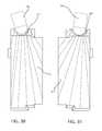
- FIG. 1Ais a view of a first type of design
- FIG. 1Bis a view of a second type of design
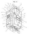
- FIG. 1Cis a bottom left perspective view of one embodiment
- FIG. 2is a top right perspective view of the embodiment shown in FIG. 1 ;
- FIG. 3is a front view of the embodiment shown in FIG. 1 ;
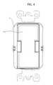
- FIG. 4is a front view of another embodiment
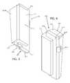
- FIG. 5is a bottom-left perspective view of the left light pipe shown in FIG. 3 ;
- FIG. 6is a top-right perspective view of the left light pipe shown in FIG. 3 ;
- FIG. 7is a left side view of the left light pipe shown in FIG. 3 ;
- FIG. 8is a right side view of the left light pipe shown in FIG. 3 ;
- FIG. 9is a back view of the left light pipe shown in FIG. 3 ;
- FIG. 10is a bottom-left perspective view of the right light pipe shown in FIG. 3 ;
- FIG. 11is a top-right view of the right light pipe shown in FIG. 3 ;
- FIG. 12is a right side view of the right light pipe shown in FIG. 3 ;
- FIG. 13is a left side view of the right light pipe shown in FIG. 3 ;
- FIG. 14is a back view of the right light pipe shown in FIG. 3 ;
- FIG. 15is a view of a light and first light pipe combination showing a radiation pattern
- FIG. 16is a view of a light and second light pipe combination showing a radiation pattern
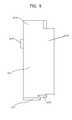
- FIG. 17is a front view of the electrical device shown in FIG. 1 with the front cover removed;
- FIG. 18is a back side view of the front cover
- FIG. 19is a front perspective view of a support piece disposed inside of the housing shown in FIG. 1 ;
- FIG. 20shows a side perspective view of the support piece shown in FIG. 19 ;
- FIG. 21is a back perspective view of the inside surface of the front cover shown in FIG. 1 ;
- FIG. 22is another back perspective view of the front cover with the light pipe being inserted
- FIG. 23is a side view of a light pipe shown in FIG. 1 ;
- FIG. 24is a cross-sectional view of the electrical device shown in FIG. 1 ;
- FIG. 25is another cross-sectional view of the electrical device shown in FIG. 1 taken along the line I-I in FIG. 26 ;
- FIG. 26is a cross sectional view of the electrical device of FIG. 1 taken along the line II-II in FIG. 25 ;
- FIG. 27is a back-cross-sectional view of the device taken along the line;
- FIG. 28shows a view of different embodiments for a left light pipe
- FIG. 29shows a view of different embodiments for a right light pipe
- FIG. 30shows a back view of an alternative design for a left light pipe
- FIG. 31shows a back view of an alternative design for a right light pipe
- FIG. 32Ashows an alternative embodiment
- FIG. 32Bshows another embodiment
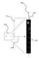
- FIGS. 1A and 1Bshow similar first and second types of designs.
- FIG. 1Ashows a first type of design, wherein there is a light or light source 50 a which is spaced at a first distance 27 a from a light pipe 20 a and showing a radiation pattern 29 a which covers only a portion of the light pipe 20 a .
- Light source 50 ahas a peak radiation pattern direction 97 a which is substantially perpendicular to a longitudinal axis 99 a of light pipe 20 a .
- 1Bshows an alternative design wherein peak radiation pattern 97 b is also substantially perpendicular to longitudinal axis 99 b of light pipe 99 b however, because light or light source 50 b is spaced at a distance 27 b which is greater than distance 27 a then this allows the radiation pattern 29 b to cover the entire length of the light pipe 20 b.
- FIG. 1Cshows a bottom left perspective view of an embodiment of an electrical device 5 having illumination.
- An example of an electrical deviceis a duplex receptacle.
- Other types of electrical devicescan comprise receptacles (duplex or not), switches, occupancy sensors, timers, fault circuit interrupters etc.
- a shown the electrical devicecan be configured to mount in a wall box.
- device 5has a housing 10 which includes a back housing 11 , a middle housing 12 and a front housing 14 wherein this housing 10 is or in at least one embodiment is configured to mount in a wall box.
- These housingscan be made from any suitable material such as metal, plastic, composite etc. In at least one embodiment the housings are made from a molded plastic.
- Front housing 14includes a front face 14 .
- the housing 10can be configured to mount in a wall box such that front face 14 . 1 is configured to be flush or substantially flush or at least parallel with an adjacent wall.
- Coupled to housing 10is at least one terminal or contact 16 which includes a screw contact 16 a .
- a clip 18is used to connect the front housing 14 , the middle housing 12 and the back housing 11 together, wherein the release of this clip allows for the disassembly of this device.
- a ground contact 17is disposed on the bottom face of this device, which is configured to connect to a ground wire to ground the electrical device.
- a cover 19is used to cover a second set of terminals 19 a and 19 b (See FIG. 2 ) as well.
- This covercan be in any suitable form but in this case is in the form of a tape which can be removed to provide access to terminals used for downstream load connection.
- Coupled to front face 14 . 1is at least one light pipe 20 for at least one light.
- a plurality of light pipes or translucent coverscomprising a first light pipe 22 , a second light pipe 24 , a third light pipe 26 and a fourth light pipe 28 .
- First light pipe 22 and second light pipe 24can, in at least one embodiment, be configured entirely different from each other.
- second light pipe 24is a minor image or substantial mirror image of first light pipe 22 .
- First light pipe 22is a left side light pipe shown in greater detail in FIGS. 5-9 .
- Second light pipe 24is a right side light pipe shown in greater detail in FIGS. 10-14 .
- These light pipesare at least partially disposed in housing 10 with at least two exposed surfaces.
- Front face 14 . 1includes a plurality of openings including a first set of openings 30 which comprise at least one prong opening for receiving a plug.
- a first set of openings 30which comprise at least one prong opening for receiving a plug.
- These openingsinclude a first blade opening 31 , a second blade opening 32 , and a ground opening 33 .
- a second set of openings 35include a first blade opening 36 a second blade opening 37 and a ground prong opening 38 .
- the electrical device 5can be either strap based or non strap based mounting device, however, this strap is shown by way of example as strap 40 .
- This strapshows screws which can be used to mount the device into a wall box.
- the devicecan be of any suitable size, however the device 5 is configured to be mounted into a single gang wall box.
- FIG. 3shows dashed lines 141 L, 142 L, 141 w and 142 w forming longitudinal and latitudinal lines defining different areas on the front face.
- Longitudinal lines 141 L and 142 Lextend along the length of the face 14 . 1 and define the width extension across the front face for each of light pipes 22 and 24 .
- light pipe 22extends at least 15% of the distance 14 . 1 w across front face 14 . 1 , and also extends at least 20% of a length along front face 14 . 1 .
- FIG. 4simply shows a simplified front face with a region or area 120 which is configured to receive any type of interactive feature for any type of suitable electrical device. Electrical devices as described above including occupancy sensors, switches, dimmers, light control timers, remote control lighting systems, or any other type of system can be used.
- the electrical device in this exampleis configured as a fault circuit interrupter including the reset button 90 and the test button 92 . While one embodiment includes a standard ground fault circuit interrupter, other embodiments are not limited to ground fault circuit interrupters. Alternatively in any other embodiment, this device includes any one of an arc fault circuit interrupter, leakage currents interrupter (LCDI) residual current circuit interrupter, immersion detection circuit interrupter, shield leakage circuit interrupter, overcurrent circuit interrupter, undercurrent circuit interrupter, overvoltage, undervoltage circuit interrupter, line frequency circuit interrupter.
- LCDIleakage currents interrupter
- the circuit interrupteris configured in at least one embodiment to determine any one of the following line characteristics noise, spike, surge, and/or any other electrical fault conditions.
- the deviceis also configured to connect in any known way such as directly to a power distribution network or through a connection to a plug tail type connection such as that shown in U.S. Pat. No. 7,357,652 which issued on Apr. 15, 2008, the disclosure of which is hereby incorporated herein by reference or by a connection shown in U.S. patent application Ser. No. 12/685,656 filed on Jan. 11, 2010 the disclosure of which is hereby incorporated herein by reference.
- FIG. 4there is a region 145 wherein any other suitable electrical device can be used such as described above in the list of electrical devices. Therefore, this region 145 defines the region to place these electrical devices.
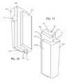
- FIGS. 5 and 6are perspective views of a light pipe 22 which is installed into housing 10 .
- Light pipe 22is made from any suitable transparent or translucent material such as a solid acrylic or polycarbonate material.
- the term translucent materialrefers to any material which is configured to allow light to pass there-through, regardless of visibility while the term transparent material is a material that is both translucent but also allows for substantial visibility through this light pipe. Therefore, as an example, a translucent light pipe could be a frosted light pipe while a transparent light pipe is for example a clear light pipe.
- Light pipe 22comprises at least three different sections 22 . 1 , 22 . 2 . and 22 . 3 .
- First section 22 . 1is the outside emitting section which is configured as substantially L-shaped and which is coupled to the second and third sections 22 .
- first surface 22 . 1includes a first section 22 . 1 a configured to shine through the front side of the device, while surface 22 . 2 b is configured to be positioned to shine out the lateral side of the device.
- These two sections 22 . 1 a and 22 . 1 bare exposed surfaces which are oriented substantially perpendicular to each other.
- Section 22 . 2includes a first surface 22 .
- Third section 22 . 3has side surfaces and a back reflective surface 22 . 5 which is configured to reflect light up and out of the housing.
- tab 22 . 4formed as a protrusion from a lateral non observant side of the light pipe and configured to lock the light pipe therein.
- combination surfaces 22 . 4 , 22 . 6 , 22 . 7 . 22 . 8 and 22 . 9Another surface 22 . 6 is configured to be in contact with, or disposed adjacent to an LED light as shown in FIG. 17 .
- the opposite spaced surfaces 22 . 7 , 22 . 8 and 22 . 9in one embodiment are translucent or transparent but in another embodiment are configured as reflective, to reflect the light inserted into the light pipe.
- stepped surfacesparticularly surfaces 22 . 8 , and 22 . 9 provide a stepped flange surface area 22 . 2 a for mounting the light pipe inside the housing.
- this angled surfaceis formed by back surface 22 . 5 , such that light which is projected into this light pipe is reflected up and out from the light pipe.
- the angle 23 which is formed from this angled surfacecan be in the range of approximately 1-33 degrees depending on the dimensions of light pipe 22 or the desired amount of reflected light into the light pipe.
- the angleis calculated as the degrees from a line 23 a , wherein this line is substantially parallel with a longitudinal axis 99 c of light pipe 22 and also substantially parallel with front face 14 . 1 of front cover wherein light pipe 22 is mounted in the housing. This angle can also be calculated as the angle relative to front face 22 .
- back surface 22 . 5extending along the length of this light pipe 22 from a first position to a second position, back surface 22 . 5 gradually slopes towards the front face 22 . 1 a , and towards a peak radiation pattern axis 97 (see FIG. 15 ) when light pipe 22 is installed into the housing.
- the first position, 22 . 5 ais closer to the light but further away from front face 14 . 1 than second position 22 . 5 b which is farther away from the light source but closer to front face 14 . 1 .
- back surface 22 . 5is an internally reflective surface which reflects light into the light pipe as it is emitted from the light/light source 50 or 60 .
- This internally reflective surfacecan be formed by the boundary of the light pipe, based upon the optical properties of the material and the intersection angle of the light, or formed by a coating or application of another material onto the boundary of the light pipe forming a reflective surface.
- Angle 23is calculated based upon the index of refraction for the material used in light pipe 22 .
- the light pipecomprises a polycarbonate. Therefore, based upon the optical properties of polycarbonate, an angle 23 , that is less than 33 degrees would be sufficient to refract, or reflect light back into the light pipe.
- this angled surface 22 . 5is configured to reflect a predetermined amount of primary light.
- the angled surfaceis configured to reflect an entire amount or at least a substantial amount of primary light emitted from a light source such as a LED light 50 , or LED light 60 .
- LED lightssuch as lights 50 and 60 form a light source disposed adjacent to a light pipe such as light pipes 22 and 24 .
- These light sources 50 and 60are configured to project primary light into the light pipes.
- Primary lightis essentially light inserted into a light pipe that is not yet internally reflected by one of the light pipe's surfaces. While polycarbonateis simply an example of one type material, other materials can be used as well. Therefore, other angles of incidence could be calculated based upon the index of refraction. Therefore, the angle of incidence which is low enough to cause reflection back into the light pipe is a reflection angle, while the angle of incidence which is high enough to cause light to be emitted from the light pipe is an emission angle.
- LED light 50is pointed along the longitudinal axis of light pipe 22 such that the peak radiation pattern extends along an axis such as along arrow 97 shown in FIG. 15 .
- angled surface 22 . 5is used. Therefore, for purposes of creating an entirely reflective surface, any angle up to the angle of emission can is used. However, the steeper the angle 23 that is used, the greater the amount of light that is reflected back into the light pipe, and out from surfaces 22 . 1 and 22 . 2 .
- light pipe 22becomes more efficient in emitting light thereby insuring that the peak radiation pattern axis 97 is directed towards the angled surface 23 and, wherein when the angle becomes greater up to the emission angle, a greater portion of the radiation pattern is then internally reflected into the light pipe.
- angle 23is calculated as 4 degrees.
- One benefit from having a light pipe with two exposed surfaces such as surfaces 22 . 1 and 22 . 2is that light is projected from both of these two different surfaces to spread light throughout an illuminated area. If surface 22 . 2 was not exposed outside of cover 14 , then the additional area of illumination provided by these two different surfaces would not be available.
- surface 22 . 1extends on a plane that is perpendicular or at least substantially perpendicular to surface 22 . 2 . Thus three factors can be considered when determining an angle of extension of back surface 22 .
- angle 23such as angle 23 : 1 ) the angle of incidence where light would leave light pipe 22 ; 2 ) an angle sufficient to provide an efficient projection of light from light pipe 22 ; 3 ) an angle sufficient to provide a second side surface such as surface 22 . 2 for projection of light.
- the back angled surface 22 . 5can either be coated with a reflective material or not. Because the angle 23 is designed within the reflective optical properties of the light pipe, the light that is initially output from either light 50 or light 60 is initially refracted back internally on the light pipe.
- FIG. 9shows a back surface 22 . 5 of light pipe 22 which shows as reflective back surface, configured to allow light which shines into the light pipe to be reflected up and out of the light pipe.
- this surfaceis not reflective.
- FIGS. 10-16show the similar features of left light pipe 24 .
- Left light pipe 24is constructed at a minor image of light pipe 22 with the corresponding surfaces performing the same or similar tasks.
- FIGS. 10 and 11are perspective views of a light pipe 24 which is installed into housing 10 .
- Light pipe 24is made from any suitable transparent or translucent material such as a solid acrylic material.
- Light pipe 24comprises at least three different sections 24 . 1 24 . 2 . and 24 . 3 .
- First section 24 . 1is the outside emitting section which is configured as substantially L-shaped and which is coupled to the second and third sections 24 . 2 and 24 . 3 .
- Second section 24 . 2is a light transmitting intermediate section, while third section 24 .
- first section 24 . 1includes a first section or surface 24 . 1 a configured to shine through the front side of the device, while section 24 . 1 b extends substantially perpendicular to first surface 24 . 1 a and is configured to be positioned to shine out the lateral side of the device.
- Section 24 . 2includes a first surface 24 . 2 a which is considered a flange surface or tongue surface which is configured to lock the light pipe inside of the housing. This surface is mounted flush to the inside surface of the front face 14 . 1
- Third section 24 . 3has side surfaces and a back internally reflective surface 24 . 5 which is configured to reflect light up and out of the housing.
- Tab 24 . 4extends out from a lateral side of the light pipe.
- the opposite spaced surfaces 24 . 7 , 24 . 8 and 24 . 9in one embodiment are translucent or transparent but in another embodiment are configured as reflective, to reflect the light inserted into the light pipe.
- stepped surfacesparticularly surfaces 24 . 8 , and 24 . 9 provide a stepped flange surface area 24 . 2 a for mounting the light pipe inside the housing.
- this angled surfaceis formed by back internally reflective surface 24 . 5 , such that light which is projected into this light pipe is reflected up and out from the light pipe.
- the angle 25extends from a first position 24 . 5 a to a second position 24 . 5 b and which is formed from this angled surface can be in the range of approximately 1-33 degrees depending on the dimensions of light pipe 24 .
- the angled surfaceextends from first position 24 . 5 a , which is a position closer to light 60 to second position 24 . 5 b which is farther from light 60 but closer to front face 14 .
- FIG. 12also shows the longitudinal axis 99 d of light pipe 24 which extends parallel or substantially parallel with line 25 a and also parallel or substantially parallel to front face 14 . 1 . With both longitudinal axes 99 c and 99 d these axes extend along the length or the longest dimension of these light pipes.
- FIG. 14shows a back surface 24 . 5 having two different surfaces 24 . 5 c and 24 . 5 d wherein surface 24 . 5 c is flat or substantially flat, while surface 24 . 5 d is an angled reflective surface. Reflective back surface 24 . 5 d is configured to allow light which shines into the light pipe to be reflected up and out of the light pipe. In at least one alternative embodiment, this surface is not reflective.
- FIG. 14also shows a light such as light 50 or 60 having a light source which is positioned at an end surface such as end surface 22 . 3 or 24 . 3 (See FIGS. 6 and 11 ) which emits a radiation pattern into the associated light pipe 22 or 24 . The radiation pattern forms a light beam area.
- this light translationallows lights to be positioned in any desired direction inside of a housing. This allows for the positioning of lights such as LED lights into a housing having space constraints, allowing for additional electronic components to be fit into the housing.
- Another benefitis that because much of the light radiation inserted into the light pipe is internally reflected from a point inside the light pipe to outside of this light pipe, the light pipe can provide the appearance of a substantially uniform source of light with few, or no detectable peak radiation points.
- FIG. 17shows a front or plan view of the device which includes light pipes 22 and 24 , middle housing 12 , lights 50 and 60 reset button 90 and test button 92 .
- a plurality of tamper resistant shutters 80are disposed inside the housing. Examples of tamper resistant shutters include those shown in U.S. Pat. No. 7,455,538 which issued on Nov. 25, 2008, and U.S. Pat. No. 7,551,047 which issued on Jun. 23, 2009. The disclosure of both patents are hereby incorporated herein by reference in their entirety.
- Another example of a shutter type designis U.S. Pat. No. 7,651,347 which issued on Jan. 26, 2010 the disclosure of which is hereby incorporated herein by reference in its entirety.
- Lights 50 and 60can be in the form of any suitable light. In this embodiment there are shown two different LED lights, with a first light 50 and the second light 60 being positioned to extend and to project light in a plane substantially parallel with front face 14 . 1 of housing 14 . Each light 50 or 60 is positioned to form an L-shaped or substantially L-shaped electrical connection with an underlying circuit board (See FIG. 24 ).
- Tamper resistant shutters 80are shutters configured to restrict the access of outside elements or foreign objects into an interior section of the housing where electrical contacts are located.
- the shuttersare configured to move axially, in the direction of arrow lines 88 and 89 , and to be biased in a closed direction via a spring (See FIG. 24 .).
- these shuttersare optional and the axial movement of the shutters is also optional. Other movements can be incorporated to restrict access to the electrical contacts.
- section 82 b and 86 bis positioned behind phase blade openings 32 and 37 .
- thisprovides pressure on the shutter causing the axial motion of the plug to translate into substantially perpendicular axial motion in the direction of arrows 88 and 89 .
- First shutter 82is biased in a closed position via spring 83 which can be any type of spring but in this embodiment is a coil spring wrapped around post 84 .
- Second shutter 86is biased in a closed position via spring 85 which can be any type of spring such as a coil spring wrapped around post 87 .
- Posts 84 and 87are positioned in a peripheral region of the housing adjacent to the side walls to provide room for the additional components such as the lights and light pipes.
- the LED lights and light pipesare positioned so as to reduce the amount of space taken by these lights while maximizing the amount of light emitted out of these light pipes.
- a fault circuit interruptersuch as a ground fault circuit interrupter
- sensorscoupled to the circuit board as well wherein at least one sensor is configured as a light sensitive sensor along with a switch which is configured to selectively turn on or off lights 50 and 60 depending on an amount of ambient light.
- This designalso includes an optional additional photodiode 15 which is positioned adjacent to light 50 and which is configured to read any input of light into light pipe 26 (See FIG. 22 ).
- light 50can be selectively switched on and off to selectively emit light out from light pipe 26 as well.
- FIG. 18is a bottom perspective back view of front cover 14 with a first light pipe or left light pipe 22 being snapped into cover 14 , and with another light pipe 24 already being snapped in place.
- a post 126which is configured to assist in locking light pipe 22 therein, wherein tab 22 . 4 extends out from a lateral side of light pipe 22 .
- tab 22 . 4snaps into opening 122 to keep this light pipe locked in place.
- light pipe 24 which is snapped in placehas tab 24 . 4 (See FIG. 18 ) snapped into opening 124 .
- posts 126 and 128are configured to also assist in locking these light pipes 22 and 24 in place.
- cover 14also contains recesses or slots 150 and 160 which can be in the form of substantially cylindrical recesses which are configured to hold lights such as LED lights 50 and 60 in place.
- recesses or slots 150 and 160which can be in the form of substantially cylindrical recesses which are configured to hold lights such as LED lights 50 and 60 in place.
- recess 150is positioned over light 50 while recess 160 is positioned over light 60 . Because these recesses are substantially cylindrical, and essentially wrap around this light they form both a support surface and a reflective surface directing light forward into the adjacently positioned light pipe.
- FIG. 19is a molded block 130 of supporting surfaces which are positioned inside of the housing.
- This molded blockcan be any suitable shape, however in this example, is Y-shaped or substantially Y-shaped.
- Arms 132 and 134are configured to support the light pipes 22 and 24 respectively inside of the housing and include a support surface dimensioned to support back surfaces 22 . 5 and 24 . 5 in an angled manner.
- a plurality of recesses 136 and 138are positioned inside of this support block 130 , and opposite corresponding recesses 150 and 160 .
- light 50is disposed between support block 130 and cover 14 wherein light 50 rests in recess 136 and recess 150 , while light 60 rests in recess 138 and recess 160 .
- This viewalso shows tongue 139 , and also posts 135 . 1 and 137 . 1 .
- Post 135 . 1divides two tracks or gaps 135 . 2 and 135 . 3 for receiving electrical connections associated with light 50 .
- post 137 . 1divides two tracks or gaps 137 . 2 and 137 . 3 for receiving electrical connections associated with light 60 .
- This molded blockcan also include a notch or cut out 78 for receiving a photodiode sensor.
- FIG. 20shows a side view of this support surface 130 , which shows arms 132 and 134 which are formed ramp shape and which are configured to support associated light pipes 22 and 24 in an angled manner.
- light lead lines 63 and 67extend down tracks 137 . 2 . and 137 . 3 (See FIG. 19 ) to circuit board 200 as well.
- Circuit board 200includes connections to these lead lines as well as connections to at least one light sensor, configured to selectively turn on or off lights 50 and 60 depending on the amount of ambient light and also includes a power or driver circuit which is configured to take power from either another circuit board such as circuit board 200 or directly from contacts 16 a , 16 b , to power the lights.
- the sensorselectively connects or disconnects power between the driver circuit and the associated lights 50 and 60 .
- This viewalso shows photodiode sensor 79 which is positioned in notch 78 .
- there are optional cut outs 132 . 1 and 134 . 1which are configured to receive a flexible or spongy material such as an optional flexible or spongy block 133 .
- Flexible or spongy block(s) 133can be inserted into any one of cut outs 132 . 1 . and 134 . 1 and are used provide a springy surface for supporting a light pipe, allowing the light pipe to be fit snugly into the housing.
- support element 130is configured, particularly posts, 135 . 1 and 137 . 1 and associated tracks 135 . 2 and 135 . 3 and 137 . 2 . and 137 . 3 so that it allow for simple manufacturing design.
- a LEDcan be secured to a circuit board such as circuit board 200 with lead lines 53 and 55 and 63 and 67 being soldered or otherwise connected to circuit board 200 .
- the associated lights 50 and 60can then be simply laid into recess 136 or 138 without any additional configuration. Therefore, the steps for manufacture would include coupling a LED to a circuit board and then providing a support block inside of a housing having a predetermined size such that it supports the already mounted LED.
- the predetermined sizing of the support 130is a predetermined size of the posts 135 . 1 and 137 . 1 and the associated tracks 135 . 2 , 135 . 3 and 137 . 2 and 137 . 3 .
- the sizing of the tracksis substantially similar to the length of any lead lines such as lead lines 53 , and 55 or 63 and 67 from associated lights 50 and 60 . The end result is that there is little or no slack in the lead lines which would cause any interference or inadvertent shorting of these lines because these lines would be both divided by their respective posts 135 . 1 and 137 . 1 and be held in a taut or at least substantially taut manner.
- FIG. 21is another back perspective view of the cover 14 which shows post 128 as well as recess 160 and an additional recess 170 .
- Additional recess 170is configured to receive additional light pipe 26 .
- Recess 170includes a tab 172 and a hole 174 .
- Tab 172acts as a protrusion which is configured to extend into light pipe 26 to lock it in place.
- recess 170also includes an opening or a hole 174 which allows light pipe 26 to extend out flush with cover 14 and forms an opening to allow light to shine through.
- There is also a rim 176which is configured to receive an arm of light pipe 26 which extends around light pipe 26 .
- This viewalso shows an opening 240 in face 14 which is configured to let light pass from to housing and out from light pipe 24 .
- an opposite spaced opening 220is shown in FIG. 18 .
- FIG. 22shows light pipe 26 snapped into recess 170 .
- a wall 141which isolates a sliding latch section from a light pipe section inside of the housing.
- FIG. 23shows an internal view of this light pipe 26 , which as shown in FIG. 1 is a L-shaped light pipe.
- a light pipe body 260In this view there is a light pipe body 260 , a light emitting region 262 extending along a lateral side of cover 14 .
- a securing arm 264which is configured to lock light pipe 26 in place with arm 264 wrapping around rim 176 .
- Arm 264includes at least two protrusions 265 and 266 which extend out from this arm and which extend towards wall 141 .
- Light pipe 26also includes an additional face or surface 268 which extends substantially perpendicular to light emitting region 262 .
- This additional face or surface 268includes an additional extended surface 269 extending out from surface 268 .
- FIG. 24shows a back cross-sectional view of the device which shows cover 14 , lights 50 and 60 disposed in a nested position in the cover, and disposed adjacent to corresponding light pipes 22 and 24 , such that light 50 is disposed adjacent to light pipe 22 and light 60 is disposed adjacent to light pipe 24 .
- FIG. 25shows a side cross-sectional view of the device taken along the line I-I of FIG. 26 .
- This viewshows shutters 82 and 84 which are disposed in front of contacts 93 and 97 , forming prong contacts for contacting with prongs of a plug.
- a power sourcesuch as by connecting distribution wiring to contacts 16 a and 16 b
- these prong or face contactswould then selectively receive power based upon whether a set of movable contacts are in a closed or latched position.
- a set of contacts 230are shown in an open position.
- light pipe 22is positioned situated on top of leg 132 of support surface 130 , wherein leg is formed in an angled manner providing the angled surface for light pipe 22 .
- this viewalso shows base circuit board 201 which is configured to house sensors, and other electrical components relating to the optional fault circuit or other optional features.
- FIG. 26shows a side cross-sectional view of the device taken along the line II-II of FIG. 25 .
- This viewshows contacts 230 and 240 which are positioned in an unlatched or open position.
- first circuit board 200positioned spaced apart from second circuit board 201 .
- second circuit boardhouses sensors 180 and 190 (not shown) inside of a sensor housing 181 and provides power and switching instructions to contacts 230 and 240 of the optional fault circuit.
- contacts 16 a and 16 bare also shown which are used to provide power to circuit board 201 via power contact lines 203 and 204 .
- circuit board 200is powered from lead lines 205 and 206 which connect to face terminals such as face terminals 93 .
- Face terminal 93also has lead lines 207 and 208 coupled thereto to power circuit board 200 as well.
- This viewalso shows photodiode 15 which is configured to sense light through additional light pipe 26 wherein this photodiode forms a sensor for detecting ambient light outside of the housing.
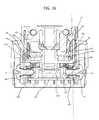
- FIG. 27is a back cross-sectional view taken along the line III-IIIa type of electrical device of FIG. 1 .
- This devicethat can be used with these light pipes, shows a plurality of transformers 180 and 190 positioned in a nested or concentric configuration and disposed inside of the back cover 11 .
- this viewshows circuit board 201 which includes contact points 55 , 56 , 65 , and 66 which are configured to connect to sensors 180 and 190 .
- this faultis indicated to a sensor circuit disposed on circuit board 201 .
- the sensor circuitdetermines whether to disconnect contacts 230 or 240 , which would then isolate load contacts 19 a and 19 b from input contacts 16 a and 16 b .
- prong or face contactssuch as contacts 93 and 97 (See FIG. 25 ) are also disconnected from power.
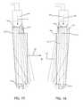
- FIGS. 28 and 29show multiple different side view of different embodiments of light pipes 22 and 24 .
- FIG. 28shows a side view of a light pipe such as for example light pipe 22 .
- This viewshows other internally reflective surfaces that can be used such as surface 227 which is at an angle greater than the angle formed for internally reflective surface 22 . 5 that is shown in FIG. 7 .
- element 228shows another angled internally reflective surface which starts at an intermediate point of angled surface 22 . 5 and extends at a steeper angle.
- there is also another internally reflective surface 229which is shown parabolic in shape.
- FIG. 29also shows different designs, wherein one design shows internally reflective surface 247 which extends at an angle greater than that shown in FIG. 12 .
- element 248shows another angled internally reflective surface which starts at an intermediate point of angled surface 24 . 5 and extends at a steeper angle.
- another designwhich shows a parabolic or curved internally reflective surface which is used to reflect light internally inside the light pipe.
- Each of these internally reflective surfacesare can be formed by a roughened outer surface, the properties of the material itself, or via a coating on the surface, or simply a reflective surface applied to the outer surface of a light pipe or fiber optic, or positioned adjacent to the outer surface of the light pipe or fiber optic.
- FIG. 30shows another design which shows a back view of a light pipe such as left light pipe 22 with a cut out or curved receiving region 229 which is configured to receive a light or light body such as LED light 50 .
- FIG. 31shows another design for right light pipe 24 which shows a cut out region or curved interface 249 which is configured to receive light 60 .
- FIG. 32Ashows an alternative design which shows LED light 50 acting as a light source which is directed into a fiber optic 58 which is configured to internally reflect light along the path of this fiber optic and into light pipe 226 at interface 59 .
- This fiber opticacts as a waveguide having outer surfaces that are internally reflecting and which are used to guide the light to the interface without substantial loss.
- this fiber opticforms a light source which projects light into the light pipe 226 .
- a first light source 50can be spaced apart from light pipe 226 and also be positioned at any desirable angle while also forming a light source at interface 59 while still having a substantial portion of the light extending along the longitudinal axis 99 d of the associated light pipe.
- FIG. 32 Bshows an alternative design with a light 50 forming a light source which is configured to project a light into a light pipe 228 .
- the light pipe 228can be formed having a substantially rectangular cross-sectional surface area, with a first type of back surface 229 a which extend substantially parallel to a longitudinal axis 229 c of the light pipe and also substantially parallel to a front surface 14 . 1 of the front face.
- light pipe 228can have an angled surface 229 b which is angled relative to longitudinal axis 229 and angled relative to the front face 14 . 1 as well.
- the light sourcesuch as light 50 , 60 , or fiber optic face 59 and back surface such as back surface 22 . 5 , 24 . 5 229 a , or 229 b are angled relative to this back surface so that a substantial portion of primary light is reflected back internally into the light pipe so as to create substantial internal reflection and sufficient and substantially even dispersion of light inside of the light pipe.
- substantial portion of primary lightcould be any amount of light that is greater than 30%, greater than 50%, greater than 60%, greater than 70%, 80%, or 90%.
- the efficiency of this reflective surfaceis controlled by the optical properties of the material of the light pipe as well as the optical properties of the reflective surface itself.
- a fault circuit interrupterhas a plurality of sensors in a substantially shallow configuration such as that disclosed in International Patent application Serial No. PCT/US09/49840 filed on Jul. 7, 2009 the disclosure of which is hereby incorporated herein by reference. Therefore, with this type of electrical device, disposed in a compact housing, there is a substantial amount electrical components positioned in a single gang electrical enclosure having a shallow depth. For example, while these dimensions are not required, an example of the dimensions of the housing are as follows: overall height OH (See FIG. 26 ) at or up to 1.380 inches in a first embodiment; or not more than 1.4 in a second embodiment or .up to not more than 1.75 inches in a third embodiment. The overall width or OW (See FIG.
- a first embodimentin a first embodiment is at or up to 1.73 inches, at or up to 1.75 inches in a second embodiment; or at or up to 1.9 inches in a third embodiment; overall length or OL (See FIG. 27 ) which is at or up to 2.7 inches in a first embodiment; at or up to 2.8 inches in a second embodiment or at or up to 3.5 inches.
- the devicecan have an in box depth of at or up to 1.02 inches in a first embodiment.
- the in box depth IBDwhich is the depth from the strap 40 to the back of the electrical device (see FIG. 2 ) can be greater such as at or up to 1.2 inches or at or up to 1.5 inches.
- An example of a decorator width which is the width of the visible face after installation of the device and which is shown by example by line 14 . 1 w in FIG. 2can be at or up to 1.28 inches in one embodiment, or at or up to 1.3. inches in a second embodiment, or at or up to 1.5 inches in a third embodiment.
- An example of a decorator length which is the length of the visible face after installation of the device which is shown by example by line 14 . 1 L in FIG. 2is at or up to 2.6 inches in a first embodiment, or at or up to 2.7 in a second embodiment, or at or up to 2.8 inches in a third embodiment.
- multiple electrical componentsincluding a fault circuit interrupter, a duplex receptacle, a plurality of lights such as three separate lights coupled to or in connection with a plurality of light pipes, can be housed inside of a housing of limited space.
Landscapes
- Physics & Mathematics (AREA)
- Engineering & Computer Science (AREA)
- Microelectronics & Electronic Packaging (AREA)
- Optics & Photonics (AREA)
- Non-Portable Lighting Devices Or Systems Thereof (AREA)
- Arrangement Of Elements, Cooling, Sealing, Or The Like Of Lighting Devices (AREA)
Abstract
Description
Claims (42)
Priority Applications (3)
| Application Number | Priority Date | Filing Date | Title |
|---|---|---|---|
| US12/856,387US8444309B2 (en) | 2010-08-13 | 2010-08-13 | Wiring device with illumination |
| CN201180038953.1ACN103069663B (en) | 2010-08-13 | 2011-08-03 | Wiring device with lighting section |
| PCT/US2011/046415WO2012021348A2 (en) | 2010-08-13 | 2011-08-03 | Wiring device with illumination |
Applications Claiming Priority (1)
| Application Number | Priority Date | Filing Date | Title |
|---|---|---|---|
| US12/856,387US8444309B2 (en) | 2010-08-13 | 2010-08-13 | Wiring device with illumination |
Publications (2)
| Publication Number | Publication Date |
|---|---|
| US20120039086A1 US20120039086A1 (en) | 2012-02-16 |
| US8444309B2true US8444309B2 (en) | 2013-05-21 |
Family
ID=45564716
Family Applications (1)
| Application Number | Title | Priority Date | Filing Date |
|---|---|---|---|
| US12/856,387Active2031-07-10US8444309B2 (en) | 2010-08-13 | 2010-08-13 | Wiring device with illumination |
Country Status (3)
| Country | Link |
|---|---|
| US (1) | US8444309B2 (en) |
| CN (1) | CN103069663B (en) |
| WO (1) | WO2012021348A2 (en) |
Cited By (10)
| Publication number | Priority date | Publication date | Assignee | Title |
|---|---|---|---|---|
| US8556651B1 (en)* | 2012-04-23 | 2013-10-15 | GM Global Technology Operations LLC | System and method for verifying assembly of a connector |
| US9091403B2 (en) | 2012-11-19 | 2015-07-28 | Pass & Seymour, Inc. | Night light |
| US20160265761A1 (en)* | 2013-11-20 | 2016-09-15 | Guangzhou Micro Welding Equipment Co., Ltd. | Electrical box having led night lamp and method for manufacturing the same |
| US9502832B1 (en) | 2015-12-07 | 2016-11-22 | Mustafa Majeed Ullahkhan | Duplex receptacle having a plurality of LEDs to illuminate the sockets |
| US9997860B1 (en)* | 2017-10-13 | 2018-06-12 | Alltrade Tools Llc | Coverplate and method for electrical outlet |
| US10566746B1 (en)* | 2019-01-29 | 2020-02-18 | George Breeden | Illuminated electricity distribution device |
| US11394157B2 (en) | 2011-08-01 | 2022-07-19 | Snaprays, Llc | Active cover plates |
| US11888301B2 (en) | 2011-08-01 | 2024-01-30 | Snaprays, Llc | Active cover plates |
| USD1038895S1 (en)* | 2021-01-05 | 2024-08-13 | Brilliant Home Technology, Inc. | Wall-mountable control device with illuminable feature |
| US12142880B2 (en) | 2011-08-01 | 2024-11-12 | Snaprays, Llc | Active cover plates |
Families Citing this family (7)
| Publication number | Priority date | Publication date | Assignee | Title |
|---|---|---|---|---|
| US9175815B2 (en)* | 2012-09-21 | 2015-11-03 | Hubbell Incorporated | Lighted electrical device and receptacle |
| USD711828S1 (en) | 2013-03-12 | 2014-08-26 | Hubbell Incorporated | Duplex receptacle with nightlight |
| USD704869S1 (en) | 2013-03-15 | 2014-05-13 | Hubbell Incorporated | Nightlight |
| USD713344S1 (en) | 2013-03-15 | 2014-09-16 | Hubbell Incorporated | Electrical receptacle with nightlight |
| BR112015011876A2 (en) | 2013-03-26 | 2017-07-11 | Halliburton Energy Services Inc | optical light tube and method for transmitting electromagnetic radiation in an optical light tube |
| USD744423S1 (en)* | 2014-06-10 | 2015-12-01 | Pass & Seymour, Inc. | Protective wiring device |
| WO2024226230A2 (en)* | 2023-04-28 | 2024-10-31 | Leviton Manufacturing Co., Inc. | Separable components in wiring devices |
Citations (376)
| Publication number | Priority date | Publication date | Assignee | Title |
|---|---|---|---|---|
| ES21345A1 (en) | 1897-08-18 | 1897-10-16 | Cole Charles Hamilton | Improvements in portable electric primary batteries. |
| GB227930A (en) | 1923-10-26 | 1925-01-26 | Reyrolle A & Co Ltd | Improvements in or relating to electric protective arrangements |
| US1875224A (en) | 1931-07-31 | 1932-08-30 | Pass & Seymour Inc | Electric wiring apparatus |
| USRE19092E (en) | 1934-02-20 | Electric wiring apparatus | ||
| US2134696A (en) | 1936-04-25 | 1938-11-01 | Morris L Bigman | Illuminated switch |
| US2154160A (en) | 1937-01-08 | 1939-04-11 | Philip E Hamilton | Attachment for electrical apparatus |
| US2189676A (en) | 1938-06-08 | 1940-02-06 | Lester J Pfohl | Electric outlet connection |
| US2246613A (en) | 1938-05-05 | 1941-06-24 | Morris L Bigman | Illuminated switch device |
| US2434065A (en) | 1945-12-29 | 1948-01-06 | Joseph F Courtney | Illuminated safety switch |
| US2494560A (en) | 1947-04-09 | 1950-01-17 | Roberts Numbering Machine Co I | Glow switch |
| US2512975A (en) | 1947-08-14 | 1950-06-27 | Elwin W Sherrard | Illuminated toggle switch |
| US2540496A (en) | 1948-04-13 | 1951-02-06 | Jerome J Sperrazza | Safety electrical receptacle |
| US2612597A (en) | 1947-09-08 | 1952-09-30 | Elwin W Sherrard | Illuminated electric outlet fixture |
| US2740873A (en) | 1952-07-17 | 1956-04-03 | Touch Plate Mfg Corp | Household switch mechanism |
| US2752581A (en) | 1955-03-30 | 1956-06-26 | Gen Electric | Convenience outlet with protective rotating shutters |
| US2826652A (en) | 1956-04-24 | 1958-03-11 | Arno E Piplack | Electric plug receptacle |
| US2926327A (en) | 1956-02-03 | 1960-02-23 | Italo Rizzieri | Socket and plug connection for electric circuits |
| GB830018A (en) | 1957-03-13 | 1960-03-09 | Michael Cornelius Gerrard | Protective device for electrical circuits and apparatus |
| US3204807A (en) | 1963-12-23 | 1965-09-07 | Sierra Electric Corp | Hinged electrical cover plate closure |
| US3222631A (en) | 1963-12-24 | 1965-12-07 | Leonard A Cohen | Electrical socket |
| US3238492A (en) | 1964-01-16 | 1966-03-01 | Hubbell Inc Harvey | Safety electric receptacle |
| US3265888A (en) | 1963-12-05 | 1966-08-09 | Hubbell Inc Harvey | Lighted receptacle |
| US3309571A (en) | 1964-03-09 | 1967-03-14 | Mc Graw Edison Co | Repeating circuit interrupter having reset control means responsive to line condition |
| US3435169A (en) | 1967-07-19 | 1969-03-25 | Leviton Manufacturing Co | Rocker type electric switch with pilot light |
| US3538477A (en) | 1965-09-20 | 1970-11-03 | Allen Bradley Co | Lever means,between protection means and switch contacts,for preventing resetting of operating mechanism if contacts are welded shut |
| US3588489A (en) | 1968-04-04 | 1971-06-28 | Sierra Electric Inc | Illuminated electrical device |
| US3617662A (en) | 1970-02-03 | 1971-11-02 | Tidewater Research Corp | Safety electrical outlet |
| US3702418A (en) | 1971-09-30 | 1972-11-07 | Texas Instruments Inc | Protection system with manual reset means operable only on clearing of the fault |
| US3731154A (en) | 1971-11-12 | 1973-05-01 | A Saakovich | Surge arrester, predominantly for power transmission lines |
| US3739226A (en) | 1971-09-08 | 1973-06-12 | W Seiter | Emergency light unit for mounting to an electrical wall outlet |
| US3746877A (en) | 1971-03-08 | 1973-07-17 | W Seiter | Emergency light unit |
| US3766434A (en) | 1971-08-09 | 1973-10-16 | S Sherman | Safety power distribution system |
| US3775726A (en) | 1971-09-13 | 1973-11-27 | R Gress | Safety receptacle |
| US3813579A (en) | 1970-11-09 | 1974-05-28 | Rucker Co | Electric receptacle assembly with ground fault protection |
| US3872354A (en) | 1973-11-19 | 1975-03-18 | Rucker Co | Portable ground fault interrupter |
| US3895225A (en) | 1974-03-29 | 1975-07-15 | Sola Basic Ind Inc | Illuminated receptacle with removable lens |
| US3949336A (en) | 1975-01-08 | 1976-04-06 | Square D Company | Sequential resetting circuit interrupter |
| US3986763A (en) | 1975-10-15 | 1976-10-19 | Midland Electric Manufacturing Company | Electric sockets |
| US3990758A (en) | 1974-05-06 | 1976-11-09 | Petterson Tor H | Child-safe electrical outlet |
| US4002951A (en) | 1975-09-22 | 1977-01-11 | Cutler-Hammer, Inc. | Electrical receptacle mounted ground fault interrupter with automatic plug insertion testing |
| US4010431A (en) | 1975-08-29 | 1977-03-01 | Westinghouse Electric Corporation | Switch for electrical wall receptacle with ground fault protection |
| US4010432A (en) | 1975-10-22 | 1977-03-01 | General Electric Company | Electrical receptacle equipped with ground fault protection |
| US4013929A (en) | 1975-04-14 | 1977-03-22 | Square D Company | Multiple duty components of a ground fault receptacle |
| US4034360A (en) | 1976-08-06 | 1977-07-05 | Schweitzer Edmund O Jun | System for disabling the reset circuit of fault indicating means |
| US4034266A (en) | 1975-08-29 | 1977-07-05 | Westinghouse Electric Corporation | Electric wall receptacle with ground fault protection |
| US4051544A (en) | 1976-03-23 | 1977-09-27 | Gte Sylvania Incorporated | Fail-safe ground fault receptacle circuit |
| US4063299A (en) | 1975-10-24 | 1977-12-13 | Eagle Electric Mfg. Co. Inc. | Magnetically latched ground fault circuit interrupter |
| US4072382A (en) | 1976-06-02 | 1978-02-07 | Reschke Kurt W | Safety outlet |
| US4086549A (en) | 1976-04-28 | 1978-04-25 | Slater Electric Inc. | Circuit interrupter relay |
| US4109226A (en) | 1977-03-01 | 1978-08-22 | General Electric Company | Disconnect switch with reset mechanism |
| US4114123A (en) | 1976-12-30 | 1978-09-12 | Texas Instruments Incorporated | Circuit breaker |
| DE2821138A1 (en) | 1977-05-17 | 1978-11-30 | Bbc Brown Boveri & Cie | ONE-PIECE ELECTRICAL EQUIPMENT |
| US4148536A (en) | 1976-11-22 | 1979-04-10 | Petropoulsos Nikolaostzakos J | Safety electrical receptacle |
| US4159499A (en) | 1977-06-20 | 1979-06-26 | Bereskin Alexander B | Ground fault detection and protection circuit |
| US4163882A (en) | 1977-12-05 | 1979-08-07 | Baslow Floyd M | Adapter for standard electrical wall fixtures |
| US4168104A (en) | 1978-06-29 | 1979-09-18 | Buschow Dean W | Electrical receptacle |
| US4194231A (en) | 1978-03-08 | 1980-03-18 | General Electric Company | Dual voltage ground fault protector |
| US4223365A (en) | 1979-03-29 | 1980-09-16 | Mcgraw-Edison Company | Auto resetting switchgear trip indicator circuits |
| US4237435A (en) | 1979-04-27 | 1980-12-02 | Gte Products Corporation | Ground fault receptacle re-set guide assembly |
| US4271337A (en) | 1979-09-17 | 1981-06-02 | Harvey Hubbell Incorporated | Safety receptacle |
| US4288768A (en) | 1978-08-04 | 1981-09-08 | Firma Heinrich Kopp Gmbh & Co. Kg. | Electrical full protection circuit breaker |
| US4316230A (en) | 1979-10-09 | 1982-02-16 | Eaton Corporation | Minimum size, integral, A.C. overload current sensing, remote power controller with reset lockout |
| US4377837A (en) | 1980-04-15 | 1983-03-22 | Westinghouse Electric Corp. | Circuit interrupter with overtemperature trip device |
| US4379607A (en) | 1980-10-06 | 1983-04-12 | Slater Electric Inc. | Shuttered receptacle |
| US4386338A (en) | 1980-11-17 | 1983-05-31 | Leviton Manufacturing Company, Inc. | Remote control system |
| USD269431S (en) | 1981-10-07 | 1983-06-21 | Leviton Manufacturing Co., Inc. | Electronic receptacle |
| EP0081661A2 (en) | 1981-10-27 | 1983-06-22 | Friedrich Lauerer | Earth fault protection device |
| US4409574A (en) | 1982-01-21 | 1983-10-11 | Westinghouse Electric Corp. | Ground fault circuit interrupter with a unified test and reset switch mechanism |
| US4412193A (en) | 1978-09-07 | 1983-10-25 | Leviton Manufacturing Company, Inc. | Resettable circuit breaker for use in ground fault circuit interrupters and the like |
| US4418979A (en) | 1981-01-21 | 1983-12-06 | Matsushita Electric Works, Ltd. | Plug socket with working condition display |
| US4442470A (en) | 1982-09-10 | 1984-04-10 | Westinghouse Electric Corp. | Ground fault receptacle with arrangement for protecting internal electronics |
| US4514789A (en) | 1984-03-07 | 1985-04-30 | Jester Michael H | Illuminated light switch plate with LED and oscillator circuit |
| US4515945A (en) | 1983-08-15 | 1985-05-07 | Ethyl Corporation | N-Alkyl-4-(4-pyridinyl)isatoic anhydrides |
| US4518945A (en) | 1980-11-17 | 1985-05-21 | Leviton Manufacturing Company, Inc. | Remote control system |
| US4521824A (en) | 1984-02-13 | 1985-06-04 | General Electric Company | Interrupter mechanism for a ground fault circuit interrupter |
| US4522455A (en) | 1983-10-11 | 1985-06-11 | Johnson Richard H | Modular electrified cover plate |
| US4538040A (en) | 1983-10-05 | 1985-08-27 | Pass & Seymour, Inc. | Electrical switch means particularly adapted to GFCI test and reset switches |
| US4544219A (en) | 1984-06-01 | 1985-10-01 | Harvey Hubbell Incorporated | Shuttered electrical receptacle |
| US4546419A (en) | 1984-11-05 | 1985-10-08 | Johnson Kelli J | Wall receptacle recessed box contained light intensity on/off controlled night light system |
| US4567456A (en) | 1983-06-13 | 1986-01-28 | Technology Research Corporation | Resettable circuit closing device |
| US4568899A (en) | 1984-03-27 | 1986-02-04 | Siemens Aktiengesellschaft | Ground fault accessory for a molded case circuit breaker |
| US4574260A (en) | 1983-12-14 | 1986-03-04 | Square D Company | Snap acting solenoid operated reset latch mechanism |
| US4578732A (en) | 1983-12-14 | 1986-03-25 | Square D Company | Ground fault circuit interrupter including snap-acting contacts |
| US4587588A (en) | 1984-03-02 | 1986-05-06 | Perma Power Electronics, Inc. | Power line transient surge suppressor |
| US4595894A (en) | 1983-12-05 | 1986-06-17 | Leviton Manufacturing Co., Inc. | Ground fault circuit interrupting system |
| US4603932A (en) | 1985-01-10 | 1986-08-05 | Heverly Karen H | Electrical outlet cover |
| US4630015A (en) | 1985-01-10 | 1986-12-16 | Slater Electric, Inc. | Ground fault circuit interrupter |
| US4631624A (en) | 1984-11-02 | 1986-12-23 | Square D Company | Time delay undervoltage release |
| US4641217A (en) | 1985-05-31 | 1987-02-03 | General Electric Company | Two pole ground fault circuit breaker |
| US4641216A (en) | 1985-04-22 | 1987-02-03 | General Electric Company | Signal processor module for ground fault circuit breaker |
| US4667073A (en) | 1985-05-03 | 1987-05-19 | Mcgill Manufacturing Company, Inc. | Electrical switch with self contained indicating means |
| US4686600A (en) | 1985-04-22 | 1987-08-11 | General Electric Company | Modular ground fault circuit breaker |
| US4714858A (en) | 1984-08-17 | 1987-12-22 | U.S. Philips Corporation | Capped electric lamp comprising a metal sleeve having a corner depression to engage an associated recess in an insulator body |
| US4719437A (en) | 1985-03-06 | 1988-01-12 | Goldstar Instrument & Electric Co. | Electrical ground fault receptacle assembly |
| US4722693A (en) | 1987-03-30 | 1988-02-02 | Friedhelm Rose | Safety shutters for electrical receptacles |
| US4755913A (en) | 1987-11-09 | 1988-07-05 | Sleveland Kenley R | Light emitting diode assembly installed on the back of an electrical switch wall plate to indicate, in the dark, the location of the switch, or to indicate at any time an electrical circuit is carrying current |
| US4774641A (en) | 1987-03-06 | 1988-09-27 | Rice Keith Q | Illuminated electric outlet cover plate |
| US4802052A (en) | 1987-01-20 | 1989-01-31 | Pass & Seymour, Inc. | Latching and release system for ground fault receptacle |
| US4814641A (en) | 1987-12-30 | 1989-03-21 | Jacques Dufresne | Electric safety supply apparatus and connector device combination |
| US4816957A (en) | 1987-08-27 | 1989-03-28 | Lawrence Irwin F | Ground line fault interrupter adapter unit |
| US4855719A (en) | 1986-10-07 | 1989-08-08 | Hermetic Switch, Inc. | Electrical receptable alarm switch |
| US4867693A (en) | 1988-08-01 | 1989-09-19 | General Electric Company | Safety electrical tap |
| US4867694A (en) | 1988-08-01 | 1989-09-19 | General Electric Company | Safety electrical receptacle |
| US4897049A (en) | 1988-08-01 | 1990-01-30 | General Electric Company | Electrical tap with permanent mount |
| US4901183A (en) | 1988-08-29 | 1990-02-13 | World Products, Inc. | Surge protection device |
| US4936789A (en) | 1989-08-01 | 1990-06-26 | Joseph Ugalde | Method and apparatus for preventing the theft of a fluorescent lamp and ballast transformer |
| US4949070A (en) | 1989-01-19 | 1990-08-14 | Wetzel Donald C | Locomotive lubrication level monitor |
| US4967308A (en) | 1989-02-13 | 1990-10-30 | Milton Morse | Enhanced safety device for an electrical appliance |
| US4979070A (en) | 1989-06-13 | 1990-12-18 | Bodkin Lawrence E | Automatic reset circuit for GFCI |
| GB2207823B (en) | 1987-06-16 | 1991-03-20 | Crabtree Electrical Ind Ltd | Improvements relating to circuit breakers |
| US5006075A (en) | 1989-02-09 | 1991-04-09 | Pass & Seymour, Inc. | Electrical receptacle with shuttered prong-receiving openings |
| US5020997A (en) | 1989-07-05 | 1991-06-04 | Bticino S.R.L. | Safety device for shielding off the receptacles of an electric current tap |
| DE3431581C2 (en) | 1984-08-28 | 1991-11-28 | Friedrich Dipl.-Ing. 8033 Krailling De Lauerer | |
| US5069630A (en) | 1990-10-01 | 1991-12-03 | Tseng Jeou N | Socket assembly for electrical plugs |
| US5117334A (en) | 1988-12-27 | 1992-05-26 | Kanto Seiki Co., Ltd. | Illuminated indicator gauge |
| US5144516A (en) | 1991-02-04 | 1992-09-01 | Wing Shing Products Company, Ltd. | Leakage current circuit interrupter device |
| US5146385A (en) | 1990-01-16 | 1992-09-08 | Hubbell Incorporated | Shallow electrical receptacle with surge suppressor and isolated ground |
| US5148344A (en) | 1990-08-06 | 1992-09-15 | Tower Manufacturing Corporation | Appliance leakage current interrupter |
| US5161240A (en) | 1990-10-26 | 1992-11-03 | Johnson Ken C | Electric wall switch with ground fault protection |
| US5179491A (en) | 1990-07-19 | 1993-01-12 | Square D Company | Plug-in circuit breaker |
| US5185687A (en) | 1991-03-28 | 1993-02-09 | Eaton Corporation | Chaos sensing arc detection |
| US5202662A (en) | 1978-09-07 | 1993-04-13 | Leviton Manufacturing Company, Inc. | Resettable circuit breaker for use in ground fault circuit interrupters and the like |
| US5218331A (en) | 1991-10-07 | 1993-06-08 | General Electric Company | Molded case circuit breaker with interchangeable trip circuits |
| US5223810A (en) | 1992-08-20 | 1993-06-29 | General Electric Company | Trip-reset mechanism for GFCI receptacle |
| US5224006A (en) | 1991-09-26 | 1993-06-29 | Westinghouse Electric Corp. | Electronic circuit breaker with protection against sputtering arc faults and ground faults |
| US5229730A (en) | 1991-08-16 | 1993-07-20 | Technology Research Corporation | Resettable circuit interrupter |
| US5239438A (en) | 1990-03-31 | 1993-08-24 | Hilti Aktiengesellschaft | Fault current protective device |
| USD342581S (en) | 1992-05-21 | 1993-12-21 | Russell Reynolds | Combined night light and electrical outlet |
| US5277607A (en) | 1993-01-15 | 1994-01-11 | The Whitaker Corporation | Electrical connector with shorting contacts which wipe against each other |
| US5277620A (en) | 1992-10-07 | 1994-01-11 | Taylor Terry A | Illuminating receptacle |
| US5293522A (en) | 1992-09-11 | 1994-03-08 | Westinghouse Electric Company | Ground fault circuit breaker with test spring/contacts directly mounted to test circuit of printed circuit board |
| US5320545A (en) | 1992-06-19 | 1994-06-14 | Brothers Harlan J | Household safety receptacle |
| US5347248A (en) | 1991-02-19 | 1994-09-13 | Heinrich Kopp Ag | Protective switching device for difference-current and undervoltage tripping |
| US5363269A (en) | 1993-02-22 | 1994-11-08 | Hubbell Incorporated | GFCI receptacle |
| US5374199A (en) | 1993-07-30 | 1994-12-20 | Chung; Chien-Lin | Safety receptacle |
| EP0411388B1 (en) | 1989-08-02 | 1995-01-11 | Henapot Ag | Emergency lighting |
| US5391085A (en) | 1993-06-24 | 1995-02-21 | Tigner; Alexander B. | Electrical socket assembly including safety device |
| US5413501A (en) | 1994-01-31 | 1995-05-09 | Munn; Roger D. | Electrical outlet |
| US5418678A (en) | 1993-09-02 | 1995-05-23 | Hubbell Incorporated | Manually set ground fault circuit interrupter |
| USD359346S (en) | 1994-07-25 | 1995-06-13 | S. C. Johnson & Son, Inc. | Dual compartment air freshener |
| US5448443A (en) | 1992-07-29 | 1995-09-05 | Suvon Associates | Power conditioning device and method |
| US5473517A (en) | 1995-01-23 | 1995-12-05 | Blackman; Stephen E. | Emergency safety light |
| US5477412A (en) | 1993-07-08 | 1995-12-19 | Leviton Manufacturing Co., Inc. | Ground fault circuit interrupter incorporating miswiring prevention circuitry |
| USD366339S (en) | 1994-03-28 | 1996-01-16 | Travis Waller | Combined electrical switch and battery powered night light |
| US5485356A (en) | 1994-11-14 | 1996-01-16 | Nguyen; Duc H. | Receptacle power indicator |
| US5510760A (en) | 1994-10-24 | 1996-04-23 | Pass & Seymour, Inc. | Ground fault interrupter wiring device with improved latching and actuating components |
| US5515218A (en) | 1993-10-05 | 1996-05-07 | Dehaven; Jeff L. | Ground fault circuit interrupter, circuit, circuit tester and method |
| US5517165A (en) | 1991-07-22 | 1996-05-14 | Pdl Holdings Limited | Switch mechanism |
| US5518132A (en) | 1995-08-04 | 1996-05-21 | Board Tech Electronic Co., Ltd. | Receptacle having protective flaps |
| US5541800A (en) | 1995-03-22 | 1996-07-30 | Hubbell Incorporated | Reverse wiring indicator for GFCI receptacles |
| US5551884A (en) | 1995-01-25 | 1996-09-03 | Burkhart, Sr.; Steven A. | Locking electrical outlet |
| US5555150A (en) | 1995-04-19 | 1996-09-10 | Lutron Electronics Co., Inc. | Surge suppression system |
| US5576580A (en) | 1993-12-28 | 1996-11-19 | Hitachi, Ltd. | DC power supply circuit |
| US5586879A (en) | 1994-07-05 | 1996-12-24 | Ford Motor Company | Fluorescent electroluminescent lamp |
| US5594398A (en) | 1994-10-24 | 1997-01-14 | Pass & Seymour, Inc. | Ground fault interrupter wiring device with improved moveable contact system |
| US5600524A (en) | 1995-05-04 | 1997-02-04 | Leviton Manufacturing Co., Inc. | Intelligent ground fault circuit interrupter |
| US5617284A (en) | 1994-08-05 | 1997-04-01 | Paradise; Rick | Power surge protection apparatus and method |
| US5625285A (en) | 1995-06-01 | 1997-04-29 | A. W. Sperry Instruments, Inc. | AC power outlet ground integrity and wire test circuit device |
| US5628394A (en) | 1996-03-25 | 1997-05-13 | Eaton Corporation | Switchgear with top mounted vertical takeoff tripping and spring release interlock |
| US5631798A (en) | 1994-06-27 | 1997-05-20 | General Electric Company | Modular accessory mechanical lock-out mechanism |
| US5637000A (en) | 1996-01-31 | 1997-06-10 | Pass & Seymour, Inc. | Electrical wiring device with ground strap shorting protection |
| US5654857A (en) | 1995-07-19 | 1997-08-05 | Leviton Manufacturing Co., Inc. | Ground fault circuit interrupt system including auxiliary surge suppression ability |
| US5655648A (en) | 1996-05-01 | 1997-08-12 | General Electric Company | Modular accessory mechanical lock-out mechanism |
| US5660459A (en) | 1996-04-19 | 1997-08-26 | E-Lite Technologies, Inc. | Illuminated assembly for a switch/outlet |
| US5661623A (en) | 1993-09-02 | 1997-08-26 | Hubbell Corporation | Ground fault circuit interrupter plug |
| US5665648A (en) | 1995-12-21 | 1997-09-09 | Hughes Electronics | Integrated circuit spring contact fabrication methods |
| US5680287A (en) | 1994-11-02 | 1997-10-21 | Leviton Manufacturing Co., Inc. | In-line cord ground fault circuit interrupter |
| US5683166A (en) | 1996-05-06 | 1997-11-04 | Lutzker; Robert S. | electroluminescent wall plate |
| US5694280A (en) | 1995-01-12 | 1997-12-02 | Pacific Sources, Inc. | Resettable latch mechanism |
| US5696350A (en) | 1995-01-18 | 1997-12-09 | Leviton Manufacturing Co., Inc. | Interchangeable sectional wallplates |
| US5702259A (en) | 1996-08-12 | 1997-12-30 | Lee; Chiu-Shan | Safety socket and plug arrangement |
| US5710399A (en) | 1996-05-01 | 1998-01-20 | General Electric Company | Electronic trip unit conversion kit for high ampere-rated circuit breakers |
| US5719363A (en) | 1995-04-08 | 1998-02-17 | Klockner-Moeller Gmbh | Mechanical switching device such as a circuit breaker and a safety device for the circuit breaker |
| USD397812S (en) | 1997-02-14 | 1998-09-01 | Custom Accessories | Electroluminescent night light |
| US5805397A (en) | 1997-09-29 | 1998-09-08 | Eaton Corporation | Arcing fault detector with multiple channel sensing and circuit breaker incorporating same |
| US5815363A (en) | 1995-06-29 | 1998-09-29 | Defond Manufacturing Limited | Circuit breaker |
| US5825602A (en) | 1996-03-26 | 1998-10-20 | Fuji Electric Co., Ltd. | Overcurrent trip device |
| US5833350A (en) | 1997-04-25 | 1998-11-10 | Electro Static Solutions, Llc | Switch cover plate providing automatic emergency lighting |
| US5839909A (en) | 1996-07-30 | 1998-11-24 | Bticino, S.P.A. | Shutter device for closing off the compartments of a power socket |
| US5844765A (en) | 1996-10-25 | 1998-12-01 | Hosiden Corporation | Power plug with a slidable lid covering a circuit protector reset knob |
| GB2290181B (en) | 1994-06-10 | 1998-12-02 | Gen Electric | Circuit breaker lockout accessory |
| US5846092A (en) | 1997-08-05 | 1998-12-08 | Minnesota Mining And Manufacturing Company | Plastic cased IC card adapter assembly |
| US5847913A (en) | 1997-02-21 | 1998-12-08 | Square D Company | Trip indicators for circuit protection devices |
| US5849878A (en) | 1993-08-13 | 1998-12-15 | The Regents Of The University Of California | Design and synthesis of bispecific reagents: use of double stranded DNAs as chemically and spatially defined cross-linkers |
| GB2292491B (en) | 1994-08-16 | 1998-12-30 | Crabtree Electrical Ind Ltd | Electric switches |
| US5875087A (en) | 1996-08-08 | 1999-02-23 | George A. Spencer | Circuit breaker with integrated control features |
| US5877925A (en) | 1996-12-17 | 1999-03-02 | General Electric Company | Ground fault-rating plug for molded case circuit breakers |
| US5883445A (en) | 1996-10-22 | 1999-03-16 | Holman; Frank T. | Power sharing device |
| US5902140A (en) | 1997-10-01 | 1999-05-11 | Recoton Corporation | Child-safe power strip |
| US5915981A (en) | 1996-06-17 | 1999-06-29 | Pass & Seymour, Inc. | Electrical receptacle with safety shutter |
| US5917686A (en) | 1992-11-16 | 1999-06-29 | Leviton Manufacturing Co., Inc. | High current ground fault circuit interrupter |
| US5920451A (en) | 1997-09-05 | 1999-07-06 | Carlingswitch, Inc. | Earth leakage circuit breaker assembly |
| US5933063A (en) | 1997-07-21 | 1999-08-03 | Rototech Electrical Components, Inc. | Ground fault circuit interrupter |
| US5934451A (en) | 1998-01-21 | 1999-08-10 | Leviton Manufacturing Co., Inc. | Illuminated rocker switch cover assembly employing electroluminescent lamp member |
| US5943199A (en) | 1997-04-22 | 1999-08-24 | Tower Manufacturing Corporation | Mini appliance leakage current interrupter |
| US5943198A (en) | 1995-05-26 | 1999-08-24 | David C. Nemir | Electrical fault interrupt circuits |
| USD413862S (en) | 1997-11-11 | 1999-09-14 | Wenzhou Van-Sheen Electric Appliance Co., Ltd. | Ground fault circuit interrupter |
| US5956218A (en) | 1994-08-24 | 1999-09-21 | Aeg Niederspannungstechnik Gmbh & Co. Kg | Earth-leakage circuit breaker with automatic monitoring capability |
| US6021034A (en) | 1997-07-23 | 2000-02-01 | Leviton Manufacturing Co., Inc. | Ground fault protection circuit for multiple loads with separate GFCI branches and a common neutral for the GFCI electronics |
| US6040967A (en) | 1998-08-24 | 2000-03-21 | Leviton Manufacturing Co., Inc. | Reset lockout for circuit interrupting device |
| EP0526071B1 (en) | 1991-07-22 | 2000-03-22 | Pdl Holdings Limited | Switch mechanism |
| US6045232A (en) | 1998-02-16 | 2000-04-04 | Buckmaster; Clifford Thoren | Apparatus for providing emergency and night lighting |
| US6052265A (en) | 1998-11-20 | 2000-04-18 | Leviton Manufacturing Co., Inc. | Intelligent ground fault circuit interrupter employing miswiring detection and user testing |
| US6078113A (en) | 1999-02-01 | 2000-06-20 | True; Mark E. | Power socket with illuminated plug blade slots |
| USD427887S (en) | 1999-02-17 | 2000-07-11 | Eagle Electric Manufacturing Co., Ltd. | Faceplate for a protective electrical receptacle |
| US6086391A (en) | 1998-04-02 | 2000-07-11 | Tzu Ying Ho | Safety socket head |
| US6089893A (en) | 1998-01-21 | 2000-07-18 | Leviton Manufacturing Co., Inc. | Illuminated electrical receptacle employing electroluminescent lamp member |
| US6111210A (en) | 1999-07-30 | 2000-08-29 | Allison; John B. | Electrical safety outlet |
| US6109760A (en) | 1998-12-14 | 2000-08-29 | Daimlerchrysler Corporation | Illuminated power outlet |
| US6149446A (en) | 1999-12-02 | 2000-11-21 | Yu; Tsung-I | Safety structure of a three-hole socket |
| US6180899B1 (en) | 1999-01-04 | 2001-01-30 | Siemens Energy & Automation, Inc. | Semi-bifurcated electrical contacts |
| US6204743B1 (en) | 2000-02-29 | 2001-03-20 | General Electric Company | Dual connector strap for a rotary contact circuit breaker |
| US6217353B1 (en) | 1999-12-01 | 2001-04-17 | Aurise Inc. | Structure of a safety receptacle |
| US6224401B1 (en) | 2000-01-27 | 2001-05-01 | Tsung-I Yu | Socket with safety device |
| US6232857B1 (en) | 1999-09-16 | 2001-05-15 | General Electric Company | Arc fault circuit breaker |
| US6238224B1 (en) | 1999-12-02 | 2001-05-29 | Hung-Chiang Shao | Safety structure in a socket |
| US6242993B1 (en) | 1995-03-13 | 2001-06-05 | Square D Company | Apparatus for use in arcing fault detection systems |
| US6246558B1 (en) | 1998-08-24 | 2001-06-12 | Leviton Manufacturing Company | Circuit interrupting device with reverse wiring protection |
| US6252407B1 (en) | 1996-12-18 | 2001-06-26 | Leviton Manufacturing Co., Inc. | Ground fault circuit interrupter miswiring prevention device |
| US6255923B1 (en) | 1999-06-25 | 2001-07-03 | General Electric Company | Arc fault circuit breaker |
| US6259340B1 (en) | 1999-05-10 | 2001-07-10 | General Electric Company | Circuit breaker with a dual test button mechanism |
| US6282070B1 (en) | 1998-08-24 | 2001-08-28 | Leviton Manufacturing Co., Inc. | Circuit interrupting system with independent trip and reset lockout |
| US6288882B1 (en) | 1998-08-24 | 2001-09-11 | Leviton Manufacturing Co., Inc. | Circuit breaker with independent trip and reset lockout |
| US6290533B1 (en) | 1999-10-05 | 2001-09-18 | Jane Major | Flashlight plug |
| US6299487B1 (en) | 2000-04-03 | 2001-10-09 | Molex Incorporated | Connector with wear-resistant engagement means |
| US6309248B1 (en) | 2000-01-27 | 2001-10-30 | Leviton Manufacturing Co., Inc. | Modular GFCI receptacle |
| US6324043B1 (en) | 1999-09-28 | 2001-11-27 | Eaton Corporation | Residual current detector with fail safe lockout device |
| US6334787B1 (en) | 2001-04-27 | 2002-01-01 | Speed Tech Corp. | Electric connector with a space-saving LED lead-out wire and circuit board arrangement |
| US6350039B1 (en) | 2000-10-06 | 2002-02-26 | Lee Chien-Yu | Wall switch and lamp assembly |
| US6381113B1 (en) | 1992-07-22 | 2002-04-30 | Technology Research Corporation | Leakage current protection device adapted to a wide variety of domestic and international applications |
| US6386725B1 (en) | 1999-10-28 | 2002-05-14 | James D. Amburgey | Surface mounted night light and socket assembly |
| US20020064779A1 (en) | 2000-02-18 | 2002-05-30 | Ulf Landegren | Methods and kits for proximity probing |
| US6412941B1 (en) | 2000-09-08 | 2002-07-02 | Tony Xin Xiao | Fully-cover shelter frame |
| US6422880B1 (en) | 2001-03-07 | 2002-07-23 | Shun-Kuo Chiu | Safety socket head |
| US6421941B1 (en) | 2000-06-30 | 2002-07-23 | Adc Telecommunications, Inc. | Designation window |
| US6433555B1 (en) | 1999-02-17 | 2002-08-13 | Eagle Electric Manufacturing Co., Inc. | Electrical circuit interrupter |
| US6437700B1 (en) | 2000-10-16 | 2002-08-20 | Leviton Manufacturing Co., Inc. | Ground fault circuit interrupter |
| USD462660S1 (en) | 2000-09-14 | 2002-09-10 | Yueqing Jiamei Electrical Co., Ltd. | Ground fault circuit interrupter |
| US20020172042A1 (en) | 2001-05-16 | 2002-11-21 | Wen-Chung Frank Tsao | Lighting fixture |
| US6488529B1 (en) | 2002-01-22 | 2002-12-03 | Taimag Corporation | Socket connector assembly used in a LAN |
| USD468033S1 (en) | 2001-04-25 | 2002-12-31 | General Electric Company | Night light adapted for air freshener |
| US20030005783A1 (en) | 1998-09-04 | 2003-01-09 | Chen James T. | Apparatus and method for automatically changing the probe head in a four-point probe system |
| US6537089B1 (en) | 2001-12-14 | 2003-03-25 | Safer Home, Inc. | Gated electrical safety outlet |
| US6537088B2 (en) | 2001-07-17 | 2003-03-25 | Atom Technology Inc. | Plug receptacle protection cover containing intermediate flexible element |
| US6545574B1 (en) | 2001-12-17 | 2003-04-08 | General Electric Company | Arc fault circuit breaker |
| US6547411B1 (en) | 2001-11-16 | 2003-04-15 | Timothy J. Dornbusch | Illuminated outlet |
| US6558928B1 (en) | 1998-03-25 | 2003-05-06 | Ulf Landegren | Rolling circle replication of padlock probes |
| US20030092297A1 (en) | 2001-11-12 | 2003-05-15 | Royal Appliance Mfg. Co. | Convenience light with supplemental electrical outlet |
| US20030102944A1 (en) | 1999-02-17 | 2003-06-05 | Eagle Electric Manufacturing Co., Inc. | Electrical circuit interrupter |
| US6580344B2 (en) | 2000-09-04 | 2003-06-17 | Huadao Huang | Ground fault interruption receptacle |
| US6590172B1 (en) | 2002-03-29 | 2003-07-08 | General Electric Company | Circuit breaker mechanism for a rotary contact system |
| US6590753B1 (en) | 2000-11-21 | 2003-07-08 | Pass & Seymour, Inc. | Ground fault circuit interrupter with indicator lamp powered from hot bus bar of interrupting contacts |
| US6593530B2 (en) | 2001-07-26 | 2003-07-15 | Torrence L. Hunt | Electrical switch identification plate with replaceable insert members |
| US20030151478A1 (en) | 2001-10-02 | 2003-08-14 | Dejan Radosavljevic | Protection device with lockout test |
| US6621388B1 (en) | 2000-04-06 | 2003-09-16 | Pass & Seymour, Inc. | Lockout mechanism for use with ground and arc fault circuit interrupters |
| US6628486B1 (en) | 2000-03-06 | 2003-09-30 | Pass & Seymour, Inc. | Fault detection device with line-load miswire protection |
| US6670872B2 (en) | 2000-07-05 | 2003-12-30 | Siemens Aktiengesellschaft | Low-voltage circuit breaker with an arc-extinguisher chamber and a switching gas damper |
| US6671145B2 (en) | 2001-03-20 | 2003-12-30 | Leviton Manufacturing Co., Inc. | Reset lockout mechanism and independent trip mechanism for center latch circuit interrupting device |
| US6734769B1 (en) | 2002-12-30 | 2004-05-11 | Leviton Manufacturing Co., Inc. | GFCI receptacle having blocking means |
| US6749449B2 (en) | 2001-08-30 | 2004-06-15 | Hubbell Incorporated | Safety receptacle with jacketed internal switches |
| US6765149B1 (en) | 2003-09-26 | 2004-07-20 | Fa Chai Ku | Wall box having light device |
| US6767228B2 (en) | 2001-06-01 | 2004-07-27 | Irwin G. Katz | Internal safety cover and method to prevent electrical shock |
| US20040147148A1 (en) | 2003-01-29 | 2004-07-29 | Koncept Technologies Inc. | Shutter assembly for receptacle |
| US6771152B2 (en) | 2001-03-21 | 2004-08-03 | Leviton Manufacturing Co., Inc. | Pivot point reset lockout mechanism for a ground for fault circuit interrupter |
| US6776630B1 (en) | 2003-10-06 | 2004-08-17 | Atom Technology Inc. | Safety socket protective cover |
| US6788173B2 (en) | 2002-05-01 | 2004-09-07 | Leviton Manufacturing Co., Inc. | Reset lockout and trip for circuit interrupting device |
| US6786745B1 (en) | 2003-08-18 | 2004-09-07 | Chyong-Yen Huang | Safety protective cover for socket receptacles |
| US6796690B2 (en) | 2002-03-14 | 2004-09-28 | The Boeing Company | LED light source |
| US6805469B1 (en) | 2003-05-03 | 2004-10-19 | R A Barton | Concealed safety lighting device |
| US6808283B2 (en) | 2001-05-16 | 2004-10-26 | Frank Wen-Chung Tsao | Sensitive lighting fixture for construction junction box |
| US6827602B2 (en) | 2003-04-30 | 2004-12-07 | Leviton Manufacturing Co., Inc. | Hospital grade receptacle with power light indicator |
| US6828886B2 (en) | 1998-08-24 | 2004-12-07 | Leviton Manufacturing Co., Inc. | Reset lockout mechanism and independent trip mechanism for center latch circuit interrupting device |
| US20050012633A1 (en) | 2003-07-11 | 2005-01-20 | Heung-Sik Yoon | Emergency lighting fixture in switch cover |
| US6857760B2 (en) | 2003-01-24 | 2005-02-22 | Chao Chuan Chien | Power outlet with night-vision-function |
| US6864769B2 (en) | 2001-03-19 | 2005-03-08 | Leviton Manufacturing Co., Inc. | Lockout mechanism for residual current devices |
| US20050063110A1 (en) | 1998-08-24 | 2005-03-24 | Disalvo Nicholas L. | Circuit interrupting device with reverse wiring protection |
| US6883927B2 (en) | 2000-01-31 | 2005-04-26 | Cube Investments Limited | Frame assembly and light for an electrical wall conduit |
| JP2005116252A (en) | 2003-10-06 | 2005-04-28 | Toyota Industries Corp | Cover and assembly for electronic apparatus mounted on structure of building |
| US6888323B1 (en) | 2002-09-25 | 2005-05-03 | The Watt Stopper, Inc. | Light management system device and method |
| USD505395S1 (en) | 2003-11-10 | 2005-05-24 | Cooper Wiring Devices, Inc. | Electrical switch |
| US6900972B1 (en) | 2001-04-09 | 2005-05-31 | Leviton Manufacturing Co., Inc. | Circuit interrupter with improved surge suppression |
| US20050124209A1 (en) | 2002-02-14 | 2005-06-09 | Currie Robert M. | Illuminated electrical cords and outlets |
| JP2005183319A (en) | 2003-12-22 | 2005-07-07 | Matsushita Electric Works Ltd | Automatic switch with hot wire sensor |
| US20050152128A1 (en) | 2004-01-14 | 2005-07-14 | Campman James P. | Switch plate lens assembly |
| US6930574B2 (en) | 2003-04-11 | 2005-08-16 | Shaohua Gao | Ground fault circuit interrupter against reverse connection error |
| US6929376B2 (en) | 2002-11-26 | 2005-08-16 | W. F. Harris Lighting, Inc. | Systems, devices and methods for lighting |
| US6937451B2 (en) | 2001-03-21 | 2005-08-30 | Leviton Manufacturing Co., Inc. | ALCI with reset lockout and independent trip |
| US6944001B2 (en) | 1998-08-24 | 2005-09-13 | Leviton Manufacturing Co., Inc. | Circuit interrupting system with independent trip and reset lockout |
| US6949994B2 (en) | 2002-12-30 | 2005-09-27 | Leviton Manufacturing Co., Inc. | GFCI without bridge contacts and having means for automatically blocking a face opening of a protected receptacle when tripped |
| US6958895B1 (en) | 2004-02-03 | 2005-10-25 | Pass & Seymour, Inc. | Protection device with a contact breaker mechanism |
| US6963260B2 (en) | 2003-02-03 | 2005-11-08 | Leviton Manufacturing Co., Inc. | GFCI receptacle having blocking means |
| US6962505B1 (en) | 2003-01-09 | 2005-11-08 | Pass & Seymar/Legrand | Electrical switch with placard and remote use indicator |
| US6969801B2 (en) | 2003-08-21 | 2005-11-29 | Pass & Seymour, Inc. | Shuttered receptacle for a protective device |
| US6979212B1 (en) | 2000-01-14 | 2005-12-27 | Protect Connect | Safety electrical plug |
| US6982856B2 (en) | 2001-03-21 | 2006-01-03 | Leviton Manufacturing Co., Inc. | GFCI with reset lockout |
| US6986589B2 (en) | 2002-01-30 | 2006-01-17 | Cyberlux Corporation | Apparatus and methods for providing an emergency lighting augmentation system |
| US6998945B2 (en) | 2003-07-17 | 2006-02-14 | Huadao Huang | Receptacle device having protection against arc faults and leakage currents |
| USD515449S1 (en) | 2005-06-10 | 2006-02-21 | Intermatic, Incorporated | Power failure switch warning light |
| USD515448S1 (en) | 2005-06-10 | 2006-02-21 | Intermatic, Incorporated | Power failure warning light |
| USD515960S1 (en) | 2005-06-10 | 2006-02-28 | Intermatic Incorporated | Power failure directional warning light |
| USD515959S1 (en) | 2005-06-10 | 2006-02-28 | Intermatic Incorporated | Power failure receptacle warning light |
| US7004595B1 (en) | 2004-03-12 | 2006-02-28 | James Marshall Stoddard | Illuminated electrical plug adapter |
| US7011422B2 (en) | 2002-10-16 | 2006-03-14 | Robertson Jonas J | Illuminated power strip and electrical outlet |
| US7019952B2 (en) | 2002-08-07 | 2006-03-28 | Shanghai Meihao Electric Inc. | Receptacle device having circuit interrupting and reverse wiring protection |
| US7026895B2 (en) | 2003-01-23 | 2006-04-11 | Leviton Manufacturing Co., Inc. | GFCI receptacle having plug blocking means |
| US7036948B1 (en) | 2003-08-11 | 2006-05-02 | Bryan Wyatt | Illuminated electrical outlet and light switch |
| US7042688B2 (en) | 2001-03-20 | 2006-05-09 | Leviton Manufacturing Co., Inc. | Neutral switch test mechanism for a circuit interrupter |
| US7045975B2 (en) | 2003-10-14 | 2006-05-16 | Cyberlux Corporation | Apparatus and methods for providing emergency safety lighting |
| US7049911B2 (en) | 2003-02-03 | 2006-05-23 | Leviton Manufacturing Co., Inc. | Circuit interrupting device and system utilizing electromechanical reset |
| US7049910B2 (en) | 1998-08-24 | 2006-05-23 | Leviton Manufacturing Co., Inc. | Circuit interrupting device with reset lockout and reverse wiring protection and method of manufacture |
| US20060139132A1 (en) | 2003-02-03 | 2006-06-29 | Porter James A | Circuit interrupting device with reverse wiring protection |
| US7081009B2 (en) | 2002-05-23 | 2006-07-25 | Protectconnect | Electrical distribution functional module |
| US7086892B2 (en) | 2003-02-28 | 2006-08-08 | Leviton Manufacturing Co., Inc. | Live circuit indicator for plugs and receptacles |
| US7118235B2 (en) | 2003-05-03 | 2006-10-10 | Robert A Barton | Concealed safety lighting device |
| USD534873S1 (en) | 2005-10-11 | 2007-01-09 | Leviton Manufacturing Co., Inc. | Dimmer paddle switch |
| US7165864B2 (en) | 2004-05-30 | 2007-01-23 | Robert Glenn Miller | Lighting fixture with night light |
| USD535627S1 (en) | 2005-10-11 | 2007-01-23 | Leviton Manufacturing Co., Inc. | Dimmer switch with lighting |
| US7168974B2 (en) | 2004-04-08 | 2007-01-30 | Leviton Manufacturing Co., Inc. | Three phase lighted plugs and connectors for indicating the absence of at least one phase |
| US20070026701A1 (en) | 2004-04-05 | 2007-02-01 | Kurek Stephen R | Electrical wiring device |
| US20070049077A1 (en) | 2005-08-31 | 2007-03-01 | Frantz Germain | Electrical wiring devices with a protective shutter |
| US20070049079A1 (en) | 2004-12-28 | 2007-03-01 | Belkin Corporation | Safety mechanism, electrical outlet containing same, and method of manufacturing same |
| US7195500B2 (en) | 2005-02-25 | 2007-03-27 | Huadao Huang | Ground fault circuit interrupter with end of life indicators |
| US7213932B1 (en) | 2003-01-09 | 2007-05-08 | Pass & Seymour, Inc. | Electrical device with lamp module |
| USD542230S1 (en) | 2005-10-11 | 2007-05-08 | Leviton Manufacturing Co., Inc. | Dimmer |
| US20070111569A1 (en) | 2005-10-31 | 2007-05-17 | Frantz Germain | Tamper proof gfci |
| USD543159S1 (en) | 2005-10-11 | 2007-05-22 | Leviton Manufacturing Co., Inc. | Dimmer switch |
| US20070114053A1 (en) | 2005-09-08 | 2007-05-24 | Cosmo Castaldo | Tamper-resistant electrical wiring device system |
| US7234844B2 (en) | 2002-12-11 | 2007-06-26 | Charles Bolta | Light emitting diode (L.E.D.) lighting fixtures with emergency back-up and scotopic enhancement |
| US20070171625A1 (en) | 2006-01-21 | 2007-07-26 | Glazner Gregory F | Switchplate Area Light |
| US20070183160A1 (en) | 2005-12-02 | 2007-08-09 | Anthony Tufano | Ceiling lamp holder to accept a non-incandescent lamp |
| US20070193866A1 (en) | 2006-01-18 | 2007-08-23 | John Eder | Lampholder |
| US7265291B1 (en) | 2002-05-23 | 2007-09-04 | Protectconnect, Inc. | Electrical distribution wiring module |
| US7265956B2 (en) | 2005-02-25 | 2007-09-04 | Huadao Huang | Ground fault circuit interrupter containing a dual-function test button |
| US20070211397A1 (en) | 2006-02-10 | 2007-09-13 | Stephen Sokolow | Tamper resistant ground fault circuit interrupter receptacle having dual function shutters |
| USD553102S1 (en) | 2005-10-11 | 2007-10-16 | Leviton Manufacturing Co., Inc. | Dimmer and on/off switch |
| US7285723B2 (en) | 2002-06-06 | 2007-10-23 | Leviton Manufacturing Co., Inc. | Receptacle with shaped surface |
| US7289306B2 (en) | 2005-02-25 | 2007-10-30 | Huadao Huang | Ground fault circuit interrupter containing a dual-function test button |
| US20070251712A1 (en) | 2006-01-23 | 2007-11-01 | Berg Michel J | Illuminated power receptacle |
| US7295415B2 (en) | 2005-02-25 | 2007-11-13 | Huadao Huang | Circuits for circuit interrupting devices having automatic end of life testing function |
| US20070291469A1 (en) | 2006-06-15 | 2007-12-20 | Wen-Pin Chen | Switch panel assembly with a light-guiding rod |
| US7312394B1 (en) | 2003-12-05 | 2007-12-25 | Pass & Seymour, Inc. | Protective device with tamper resistant shutters |
| US7315227B2 (en) | 2005-02-25 | 2008-01-01 | Huadao Huang | Ground fault circuit interrupters providing end of the life test |
| US7317600B2 (en) | 2005-02-25 | 2008-01-08 | Huadao Huang | Circuit interrupting device with automatic end of life test |
| USD564129S1 (en) | 2007-01-18 | 2008-03-11 | Leviton Manufacturing Co., Inc. | Ceiling lampholder to accept a fluorescent lamp |
| US20080073117A1 (en) | 2006-09-26 | 2008-03-27 | Donald Lowell Misener | Configurable safety light receptacle |
| US7357652B1 (en) | 2006-10-27 | 2008-04-15 | Leviton Manufacturing Company, Inc. | Modular wiring system with locking elements |
| US7360912B1 (en) | 2003-12-02 | 2008-04-22 | Pass & Seymour, Inc. | Electrical device with lamp module |
| US7416310B1 (en) | 2003-12-02 | 2008-08-26 | Pass & Seymour, Inc. | Power control device for an electrical load |
| US20080233780A1 (en) | 2007-03-22 | 2008-09-25 | Darrell Waters | Power socket having illuminated plug receiving apertures |
| US20090032278A1 (en) | 2003-12-02 | 2009-02-05 | Pass & Seymour, Inc. | Protective Electrical Wiring Device with a Center Nightlight |
| US20090035967A1 (en) | 2003-01-09 | 2009-02-05 | Pass & Seymour, Inc. | Electrical wiring device with a center nightlight and a plurality of safety features |
| US20090052162A1 (en) | 2007-08-20 | 2009-02-26 | Leviton Manufacturing Company Inc. | Combination device including a guide light and an electrical component |
| US20090103329A1 (en) | 2007-10-22 | 2009-04-23 | Ching-Huei Wu | Combination of electrical socket and night lamp |
| US20090109653A1 (en) | 2007-10-25 | 2009-04-30 | Ching-Huei Wu | Electrical socket with emergency lighting device |
| US7538647B2 (en) | 2006-07-28 | 2009-05-26 | Cooper Technologies Company | Ground fault circuit interrupter device |
| US20090141477A1 (en) | 2007-12-04 | 2009-06-04 | Pass & Seymour, Inc. | Illuminated Face Receptacle Structure |
| USD595229S1 (en) | 2008-04-25 | 2009-06-30 | Lagrotta James Thomas | Low profile plug-in GFI device |
| USD598859S1 (en) | 2007-05-31 | 2009-08-25 | Cooper Technologies Company | Ground fault circuit interrupter |
| US7586718B1 (en) | 2004-03-05 | 2009-09-08 | Pass & Seymour, Inc. | Electrical device with circuit protection component and light |
| USD601962S1 (en) | 2005-11-11 | 2009-10-13 | Zhejiang Dongzheng Electrical Co., Ltd. | Ground fault circuit interrupter (GFCI) |
| USD603983S1 (en) | 2008-05-16 | 2009-11-10 | Leviton Manufacturing Co., Inc. | Nightlight for an electrical device |
| USD603984S1 (en) | 2008-05-16 | 2009-11-10 | Leviton Manufacturing Co., Inc. | Nightlight for an electrical device |
| USD603985S1 (en) | 2008-05-16 | 2009-11-10 | Leviton Manufacturing Co., Inc. | Nightlight for an electrical device |
| USD604873S1 (en) | 2008-05-16 | 2009-11-24 | Leviton Manufacturing Co., Inc. | Nightlight for an electrical device |
| WO2010005987A2 (en) | 2008-07-07 | 2010-01-14 | Leviton Manufacturing Company, Inc | Fault circuit interrupter device |
| US7666010B2 (en) | 2006-10-27 | 2010-02-23 | Leviton Manufacturing Company, Inc. | Modular wiring system with locking elements |
| US7683745B2 (en) | 2006-07-28 | 2010-03-23 | Cooper Technologies Company | Ground fault circuit interrupter device |
| US7701680B2 (en) | 2006-11-14 | 2010-04-20 | Shanghai Ele Manufacturing Co., Ltd | Ground-fault circuit interrupter |
| USD614572S1 (en) | 2002-09-17 | 2010-04-27 | Leviton Manufacturing Co., Inc. | Multiple outlet receptacle |
| US7726825B2 (en) | 2008-02-22 | 2010-06-01 | Leviton Manufacturing Co., Inc. | Lighted power outlet system and method |
| US20100227484A1 (en) | 2006-10-27 | 2010-09-09 | Leviton Manufacturing Co., Inc. | Modular wiring system with locking elements |
| US7820909B2 (en) | 2005-09-08 | 2010-10-26 | Leviton Manufacturing Co., Inc. | Tamper-resistant electrical wiring device system |
| USD631440S1 (en) | 2006-08-31 | 2011-01-25 | Hubbell Incorporated | Multi-purpose electrical outlet |
| USD634866S1 (en) | 2008-05-16 | 2011-03-22 | Leviton Manufacturing Co., Inc. | Nightlight for an electrical device |
| US20110228552A1 (en) | 2010-03-17 | 2011-09-22 | Leviton Manufacturing Company, Inc. | Faceplate guidelight system |
| US20120170292A1 (en) | 2010-12-30 | 2012-07-05 | Leviton Manufacturing Company, Inc | Illuminated receptacle |
Family Cites Families (3)
| Publication number | Priority date | Publication date | Assignee | Title |
|---|---|---|---|---|
| CN201352656Y (en)* | 2008-12-31 | 2009-11-25 | 黄华道 | Novel multifunctional electric-leakage protection socket |
| CN201515109U (en)* | 2009-04-15 | 2010-06-23 | 黄华道 | Novel leakage protection socket |
| CN101740962A (en)* | 2010-02-12 | 2010-06-16 | 安全第一有限公司 | Electric supply installation with function of emergency illumination |
- 2010
- 2010-08-13USUS12/856,387patent/US8444309B2/enactiveActive
- 2011
- 2011-08-03WOPCT/US2011/046415patent/WO2012021348A2/enactiveApplication Filing
- 2011-08-03CNCN201180038953.1Apatent/CN103069663B/enactiveActive
Patent Citations (427)
| Publication number | Priority date | Publication date | Assignee | Title |
|---|---|---|---|---|
| USRE19092E (en) | 1934-02-20 | Electric wiring apparatus | ||
| ES21345A1 (en) | 1897-08-18 | 1897-10-16 | Cole Charles Hamilton | Improvements in portable electric primary batteries. |
| GB227930A (en) | 1923-10-26 | 1925-01-26 | Reyrolle A & Co Ltd | Improvements in or relating to electric protective arrangements |
| US1875224A (en) | 1931-07-31 | 1932-08-30 | Pass & Seymour Inc | Electric wiring apparatus |
| US2134696A (en) | 1936-04-25 | 1938-11-01 | Morris L Bigman | Illuminated switch |
| US2154160A (en) | 1937-01-08 | 1939-04-11 | Philip E Hamilton | Attachment for electrical apparatus |
| US2246613A (en) | 1938-05-05 | 1941-06-24 | Morris L Bigman | Illuminated switch device |
| US2189676A (en) | 1938-06-08 | 1940-02-06 | Lester J Pfohl | Electric outlet connection |
| US2434065A (en) | 1945-12-29 | 1948-01-06 | Joseph F Courtney | Illuminated safety switch |
| US2494560A (en) | 1947-04-09 | 1950-01-17 | Roberts Numbering Machine Co I | Glow switch |
| US2512975A (en) | 1947-08-14 | 1950-06-27 | Elwin W Sherrard | Illuminated toggle switch |
| US2612597A (en) | 1947-09-08 | 1952-09-30 | Elwin W Sherrard | Illuminated electric outlet fixture |
| US2540496A (en) | 1948-04-13 | 1951-02-06 | Jerome J Sperrazza | Safety electrical receptacle |
| US2740873A (en) | 1952-07-17 | 1956-04-03 | Touch Plate Mfg Corp | Household switch mechanism |
| US2752581A (en) | 1955-03-30 | 1956-06-26 | Gen Electric | Convenience outlet with protective rotating shutters |
| US2926327A (en) | 1956-02-03 | 1960-02-23 | Italo Rizzieri | Socket and plug connection for electric circuits |
| US2826652A (en) | 1956-04-24 | 1958-03-11 | Arno E Piplack | Electric plug receptacle |
| GB830018A (en) | 1957-03-13 | 1960-03-09 | Michael Cornelius Gerrard | Protective device for electrical circuits and apparatus |
| US3265888A (en) | 1963-12-05 | 1966-08-09 | Hubbell Inc Harvey | Lighted receptacle |
| US3204807A (en) | 1963-12-23 | 1965-09-07 | Sierra Electric Corp | Hinged electrical cover plate closure |
| US3222631A (en) | 1963-12-24 | 1965-12-07 | Leonard A Cohen | Electrical socket |
| US3238492A (en) | 1964-01-16 | 1966-03-01 | Hubbell Inc Harvey | Safety electric receptacle |
| US3309571A (en) | 1964-03-09 | 1967-03-14 | Mc Graw Edison Co | Repeating circuit interrupter having reset control means responsive to line condition |
| US3538477A (en) | 1965-09-20 | 1970-11-03 | Allen Bradley Co | Lever means,between protection means and switch contacts,for preventing resetting of operating mechanism if contacts are welded shut |
| US3435169A (en) | 1967-07-19 | 1969-03-25 | Leviton Manufacturing Co | Rocker type electric switch with pilot light |
| US3588489A (en) | 1968-04-04 | 1971-06-28 | Sierra Electric Inc | Illuminated electrical device |
| US3617662A (en) | 1970-02-03 | 1971-11-02 | Tidewater Research Corp | Safety electrical outlet |
| US3813579A (en) | 1970-11-09 | 1974-05-28 | Rucker Co | Electric receptacle assembly with ground fault protection |
| US3864649A (en) | 1970-11-09 | 1975-02-04 | Rucker Co | Electrical safety device with improved trip mechanism |
| US3746877A (en) | 1971-03-08 | 1973-07-17 | W Seiter | Emergency light unit |
| US3766434A (en) | 1971-08-09 | 1973-10-16 | S Sherman | Safety power distribution system |
| US3739226A (en) | 1971-09-08 | 1973-06-12 | W Seiter | Emergency light unit for mounting to an electrical wall outlet |
| US3775726A (en) | 1971-09-13 | 1973-11-27 | R Gress | Safety receptacle |
| US3702418A (en) | 1971-09-30 | 1972-11-07 | Texas Instruments Inc | Protection system with manual reset means operable only on clearing of the fault |
| US3731154A (en) | 1971-11-12 | 1973-05-01 | A Saakovich | Surge arrester, predominantly for power transmission lines |
| US3872354A (en) | 1973-11-19 | 1975-03-18 | Rucker Co | Portable ground fault interrupter |
| US3895225A (en) | 1974-03-29 | 1975-07-15 | Sola Basic Ind Inc | Illuminated receptacle with removable lens |
| US3990758A (en) | 1974-05-06 | 1976-11-09 | Petterson Tor H | Child-safe electrical outlet |
| US3949336A (en) | 1975-01-08 | 1976-04-06 | Square D Company | Sequential resetting circuit interrupter |
| US4013929A (en) | 1975-04-14 | 1977-03-22 | Square D Company | Multiple duty components of a ground fault receptacle |
| US4010431A (en) | 1975-08-29 | 1977-03-01 | Westinghouse Electric Corporation | Switch for electrical wall receptacle with ground fault protection |
| US4034266A (en) | 1975-08-29 | 1977-07-05 | Westinghouse Electric Corporation | Electric wall receptacle with ground fault protection |
| US4002951A (en) | 1975-09-22 | 1977-01-11 | Cutler-Hammer, Inc. | Electrical receptacle mounted ground fault interrupter with automatic plug insertion testing |
| US3986763A (en) | 1975-10-15 | 1976-10-19 | Midland Electric Manufacturing Company | Electric sockets |
| US4010432A (en) | 1975-10-22 | 1977-03-01 | General Electric Company | Electrical receptacle equipped with ground fault protection |
| US4063299A (en) | 1975-10-24 | 1977-12-13 | Eagle Electric Mfg. Co. Inc. | Magnetically latched ground fault circuit interrupter |
| US4051544A (en) | 1976-03-23 | 1977-09-27 | Gte Sylvania Incorporated | Fail-safe ground fault receptacle circuit |
| US4086549A (en) | 1976-04-28 | 1978-04-25 | Slater Electric Inc. | Circuit interrupter relay |
| US4072382A (en) | 1976-06-02 | 1978-02-07 | Reschke Kurt W | Safety outlet |
| US4034360A (en) | 1976-08-06 | 1977-07-05 | Schweitzer Edmund O Jun | System for disabling the reset circuit of fault indicating means |
| US4148536A (en) | 1976-11-22 | 1979-04-10 | Petropoulsos Nikolaostzakos J | Safety electrical receptacle |
| US4114123A (en) | 1976-12-30 | 1978-09-12 | Texas Instruments Incorporated | Circuit breaker |
| US4109226A (en) | 1977-03-01 | 1978-08-22 | General Electric Company | Disconnect switch with reset mechanism |
| DE2821138A1 (en) | 1977-05-17 | 1978-11-30 | Bbc Brown Boveri & Cie | ONE-PIECE ELECTRICAL EQUIPMENT |
| FR2391549B3 (en) | 1977-05-17 | 1981-01-09 | Elettrocondutture | PROTECTION AND CUT-OFF DEVICE FOR ELECTRICAL LINES |
| US4159499A (en) | 1977-06-20 | 1979-06-26 | Bereskin Alexander B | Ground fault detection and protection circuit |
| US4163882A (en) | 1977-12-05 | 1979-08-07 | Baslow Floyd M | Adapter for standard electrical wall fixtures |
| US4194231A (en) | 1978-03-08 | 1980-03-18 | General Electric Company | Dual voltage ground fault protector |
| US4168104A (en) | 1978-06-29 | 1979-09-18 | Buschow Dean W | Electrical receptacle |
| US4288768A (en) | 1978-08-04 | 1981-09-08 | Firma Heinrich Kopp Gmbh & Co. Kg. | Electrical full protection circuit breaker |
| US4412193A (en) | 1978-09-07 | 1983-10-25 | Leviton Manufacturing Company, Inc. | Resettable circuit breaker for use in ground fault circuit interrupters and the like |
| US5202662A (en) | 1978-09-07 | 1993-04-13 | Leviton Manufacturing Company, Inc. | Resettable circuit breaker for use in ground fault circuit interrupters and the like |
| US4223365A (en) | 1979-03-29 | 1980-09-16 | Mcgraw-Edison Company | Auto resetting switchgear trip indicator circuits |
| US4237435A (en) | 1979-04-27 | 1980-12-02 | Gte Products Corporation | Ground fault receptacle re-set guide assembly |
| US4271337A (en) | 1979-09-17 | 1981-06-02 | Harvey Hubbell Incorporated | Safety receptacle |
| US4316230A (en) | 1979-10-09 | 1982-02-16 | Eaton Corporation | Minimum size, integral, A.C. overload current sensing, remote power controller with reset lockout |
| US4377837A (en) | 1980-04-15 | 1983-03-22 | Westinghouse Electric Corp. | Circuit interrupter with overtemperature trip device |
| US4379607A (en) | 1980-10-06 | 1983-04-12 | Slater Electric Inc. | Shuttered receptacle |
| US4386338A (en) | 1980-11-17 | 1983-05-31 | Leviton Manufacturing Company, Inc. | Remote control system |
| US4518945A (en) | 1980-11-17 | 1985-05-21 | Leviton Manufacturing Company, Inc. | Remote control system |
| US4418979A (en) | 1981-01-21 | 1983-12-06 | Matsushita Electric Works, Ltd. | Plug socket with working condition display |
| USD269431S (en) | 1981-10-07 | 1983-06-21 | Leviton Manufacturing Co., Inc. | Electronic receptacle |
| EP0081661A2 (en) | 1981-10-27 | 1983-06-22 | Friedrich Lauerer | Earth fault protection device |
| US4409574A (en) | 1982-01-21 | 1983-10-11 | Westinghouse Electric Corp. | Ground fault circuit interrupter with a unified test and reset switch mechanism |
| US4442470A (en) | 1982-09-10 | 1984-04-10 | Westinghouse Electric Corp. | Ground fault receptacle with arrangement for protecting internal electronics |
| US4567456A (en) | 1983-06-13 | 1986-01-28 | Technology Research Corporation | Resettable circuit closing device |
| US4515945A (en) | 1983-08-15 | 1985-05-07 | Ethyl Corporation | N-Alkyl-4-(4-pyridinyl)isatoic anhydrides |
| US4538040A (en) | 1983-10-05 | 1985-08-27 | Pass & Seymour, Inc. | Electrical switch means particularly adapted to GFCI test and reset switches |
| US4522455A (en) | 1983-10-11 | 1985-06-11 | Johnson Richard H | Modular electrified cover plate |
| US4595894A (en) | 1983-12-05 | 1986-06-17 | Leviton Manufacturing Co., Inc. | Ground fault circuit interrupting system |
| US4578732A (en) | 1983-12-14 | 1986-03-25 | Square D Company | Ground fault circuit interrupter including snap-acting contacts |
| US4574260A (en) | 1983-12-14 | 1986-03-04 | Square D Company | Snap acting solenoid operated reset latch mechanism |
| US4521824A (en) | 1984-02-13 | 1985-06-04 | General Electric Company | Interrupter mechanism for a ground fault circuit interrupter |
| US4587588A (en) | 1984-03-02 | 1986-05-06 | Perma Power Electronics, Inc. | Power line transient surge suppressor |
| US4514789A (en) | 1984-03-07 | 1985-04-30 | Jester Michael H | Illuminated light switch plate with LED and oscillator circuit |
| US4568899A (en) | 1984-03-27 | 1986-02-04 | Siemens Aktiengesellschaft | Ground fault accessory for a molded case circuit breaker |
| US4544219A (en) | 1984-06-01 | 1985-10-01 | Harvey Hubbell Incorporated | Shuttered electrical receptacle |
| US4714858A (en) | 1984-08-17 | 1987-12-22 | U.S. Philips Corporation | Capped electric lamp comprising a metal sleeve having a corner depression to engage an associated recess in an insulator body |
| DE3431581C2 (en) | 1984-08-28 | 1991-11-28 | Friedrich Dipl.-Ing. 8033 Krailling De Lauerer | |
| US4631624A (en) | 1984-11-02 | 1986-12-23 | Square D Company | Time delay undervoltage release |
| US4546419A (en) | 1984-11-05 | 1985-10-08 | Johnson Kelli J | Wall receptacle recessed box contained light intensity on/off controlled night light system |
| US4630015A (en) | 1985-01-10 | 1986-12-16 | Slater Electric, Inc. | Ground fault circuit interrupter |
| US4603932A (en) | 1985-01-10 | 1986-08-05 | Heverly Karen H | Electrical outlet cover |
| US4719437A (en) | 1985-03-06 | 1988-01-12 | Goldstar Instrument & Electric Co. | Electrical ground fault receptacle assembly |
| US4641216A (en) | 1985-04-22 | 1987-02-03 | General Electric Company | Signal processor module for ground fault circuit breaker |
| US4686600A (en) | 1985-04-22 | 1987-08-11 | General Electric Company | Modular ground fault circuit breaker |
| US4667073A (en) | 1985-05-03 | 1987-05-19 | Mcgill Manufacturing Company, Inc. | Electrical switch with self contained indicating means |
| US4641217A (en) | 1985-05-31 | 1987-02-03 | General Electric Company | Two pole ground fault circuit breaker |
| US4855719A (en) | 1986-10-07 | 1989-08-08 | Hermetic Switch, Inc. | Electrical receptable alarm switch |
| US4802052A (en) | 1987-01-20 | 1989-01-31 | Pass & Seymour, Inc. | Latching and release system for ground fault receptacle |
| US4774641A (en) | 1987-03-06 | 1988-09-27 | Rice Keith Q | Illuminated electric outlet cover plate |
| US4722693A (en) | 1987-03-30 | 1988-02-02 | Friedhelm Rose | Safety shutters for electrical receptacles |
| GB2207823B (en) | 1987-06-16 | 1991-03-20 | Crabtree Electrical Ind Ltd | Improvements relating to circuit breakers |
| US4816957A (en) | 1987-08-27 | 1989-03-28 | Lawrence Irwin F | Ground line fault interrupter adapter unit |
| US4755913A (en) | 1987-11-09 | 1988-07-05 | Sleveland Kenley R | Light emitting diode assembly installed on the back of an electrical switch wall plate to indicate, in the dark, the location of the switch, or to indicate at any time an electrical circuit is carrying current |
| US4814641A (en) | 1987-12-30 | 1989-03-21 | Jacques Dufresne | Electric safety supply apparatus and connector device combination |
| US4897049A (en) | 1988-08-01 | 1990-01-30 | General Electric Company | Electrical tap with permanent mount |
| US4867694A (en) | 1988-08-01 | 1989-09-19 | General Electric Company | Safety electrical receptacle |
| US4867693A (en) | 1988-08-01 | 1989-09-19 | General Electric Company | Safety electrical tap |
| US4901183A (en) | 1988-08-29 | 1990-02-13 | World Products, Inc. | Surge protection device |
| US5117334A (en) | 1988-12-27 | 1992-05-26 | Kanto Seiki Co., Ltd. | Illuminated indicator gauge |
| US4949070A (en) | 1989-01-19 | 1990-08-14 | Wetzel Donald C | Locomotive lubrication level monitor |
| US5006075A (en) | 1989-02-09 | 1991-04-09 | Pass & Seymour, Inc. | Electrical receptacle with shuttered prong-receiving openings |
| US4967308A (en) | 1989-02-13 | 1990-10-30 | Milton Morse | Enhanced safety device for an electrical appliance |
| US4979070A (en) | 1989-06-13 | 1990-12-18 | Bodkin Lawrence E | Automatic reset circuit for GFCI |
| US5020997A (en) | 1989-07-05 | 1991-06-04 | Bticino S.R.L. | Safety device for shielding off the receptacles of an electric current tap |
| US4936789A (en) | 1989-08-01 | 1990-06-26 | Joseph Ugalde | Method and apparatus for preventing the theft of a fluorescent lamp and ballast transformer |
| EP0411388B1 (en) | 1989-08-02 | 1995-01-11 | Henapot Ag | Emergency lighting |
| US5146385A (en) | 1990-01-16 | 1992-09-08 | Hubbell Incorporated | Shallow electrical receptacle with surge suppressor and isolated ground |
| US5239438A (en) | 1990-03-31 | 1993-08-24 | Hilti Aktiengesellschaft | Fault current protective device |
| US5179491A (en) | 1990-07-19 | 1993-01-12 | Square D Company | Plug-in circuit breaker |
| US5148344A (en) | 1990-08-06 | 1992-09-15 | Tower Manufacturing Corporation | Appliance leakage current interrupter |
| US5069630A (en) | 1990-10-01 | 1991-12-03 | Tseng Jeou N | Socket assembly for electrical plugs |
| US5161240A (en) | 1990-10-26 | 1992-11-03 | Johnson Ken C | Electric wall switch with ground fault protection |
| US5144516A (en) | 1991-02-04 | 1992-09-01 | Wing Shing Products Company, Ltd. | Leakage current circuit interrupter device |
| US5347248A (en) | 1991-02-19 | 1994-09-13 | Heinrich Kopp Ag | Protective switching device for difference-current and undervoltage tripping |
| US5185687A (en) | 1991-03-28 | 1993-02-09 | Eaton Corporation | Chaos sensing arc detection |
| US5517165A (en) | 1991-07-22 | 1996-05-14 | Pdl Holdings Limited | Switch mechanism |
| EP0526071B1 (en) | 1991-07-22 | 2000-03-22 | Pdl Holdings Limited | Switch mechanism |
| US5229730A (en) | 1991-08-16 | 1993-07-20 | Technology Research Corporation | Resettable circuit interrupter |
| US5224006A (en) | 1991-09-26 | 1993-06-29 | Westinghouse Electric Corp. | Electronic circuit breaker with protection against sputtering arc faults and ground faults |
| US5218331A (en) | 1991-10-07 | 1993-06-08 | General Electric Company | Molded case circuit breaker with interchangeable trip circuits |
| USD342581S (en) | 1992-05-21 | 1993-12-21 | Russell Reynolds | Combined night light and electrical outlet |
| US5320545A (en) | 1992-06-19 | 1994-06-14 | Brothers Harlan J | Household safety receptacle |
| US6381113B1 (en) | 1992-07-22 | 2002-04-30 | Technology Research Corporation | Leakage current protection device adapted to a wide variety of domestic and international applications |
| US5448443A (en) | 1992-07-29 | 1995-09-05 | Suvon Associates | Power conditioning device and method |
| US5223810A (en) | 1992-08-20 | 1993-06-29 | General Electric Company | Trip-reset mechanism for GFCI receptacle |
| US5293522A (en) | 1992-09-11 | 1994-03-08 | Westinghouse Electric Company | Ground fault circuit breaker with test spring/contacts directly mounted to test circuit of printed circuit board |
| US5277620A (en) | 1992-10-07 | 1994-01-11 | Taylor Terry A | Illuminating receptacle |
| US5917686A (en) | 1992-11-16 | 1999-06-29 | Leviton Manufacturing Co., Inc. | High current ground fault circuit interrupter |
| US5277607A (en) | 1993-01-15 | 1994-01-11 | The Whitaker Corporation | Electrical connector with shorting contacts which wipe against each other |
| US5363269A (en) | 1993-02-22 | 1994-11-08 | Hubbell Incorporated | GFCI receptacle |
| US5391085A (en) | 1993-06-24 | 1995-02-21 | Tigner; Alexander B. | Electrical socket assembly including safety device |
| US6226161B1 (en) | 1993-07-08 | 2001-05-01 | Leviton Manufacturing Co., Inc. | Ground fault circuit interrupter incorporating miswiring prevention circuitry |
| US5477412A (en) | 1993-07-08 | 1995-12-19 | Leviton Manufacturing Co., Inc. | Ground fault circuit interrupter incorporating miswiring prevention circuitry |
| US5706155A (en) | 1993-07-08 | 1998-01-06 | Leviton Manufacturing Co., Inc. | Ground fault circuit interrupter incorporating miswiring prevention circuitry |
| US5729417A (en) | 1993-07-08 | 1998-03-17 | Leviton Manufacturing Co., Inc. | Ground fault circuit interrupter incorporating miswiring prevention circuitry |
| US5963408A (en) | 1993-07-08 | 1999-10-05 | Leviton Manufacturing Co., Inc. | Ground fault circuit interrupter incorporating miswiring prevention circuitry |
| US5374199A (en) | 1993-07-30 | 1994-12-20 | Chung; Chien-Lin | Safety receptacle |
| US5849878A (en) | 1993-08-13 | 1998-12-15 | The Regents Of The University Of California | Design and synthesis of bispecific reagents: use of double stranded DNAs as chemically and spatially defined cross-linkers |
| US5661623A (en) | 1993-09-02 | 1997-08-26 | Hubbell Corporation | Ground fault circuit interrupter plug |
| US5418678A (en) | 1993-09-02 | 1995-05-23 | Hubbell Incorporated | Manually set ground fault circuit interrupter |
| US5515218A (en) | 1993-10-05 | 1996-05-07 | Dehaven; Jeff L. | Ground fault circuit interrupter, circuit, circuit tester and method |
| US5576580A (en) | 1993-12-28 | 1996-11-19 | Hitachi, Ltd. | DC power supply circuit |
| US5413501A (en) | 1994-01-31 | 1995-05-09 | Munn; Roger D. | Electrical outlet |
| USD366339S (en) | 1994-03-28 | 1996-01-16 | Travis Waller | Combined electrical switch and battery powered night light |
| GB2290181B (en) | 1994-06-10 | 1998-12-02 | Gen Electric | Circuit breaker lockout accessory |
| US5631798A (en) | 1994-06-27 | 1997-05-20 | General Electric Company | Modular accessory mechanical lock-out mechanism |
| US5586879A (en) | 1994-07-05 | 1996-12-24 | Ford Motor Company | Fluorescent electroluminescent lamp |
| USD359346S (en) | 1994-07-25 | 1995-06-13 | S. C. Johnson & Son, Inc. | Dual compartment air freshener |
| US5617284A (en) | 1994-08-05 | 1997-04-01 | Paradise; Rick | Power surge protection apparatus and method |
| GB2292491B (en) | 1994-08-16 | 1998-12-30 | Crabtree Electrical Ind Ltd | Electric switches |
| US5956218A (en) | 1994-08-24 | 1999-09-21 | Aeg Niederspannungstechnik Gmbh & Co. Kg | Earth-leakage circuit breaker with automatic monitoring capability |
| US5510760A (en) | 1994-10-24 | 1996-04-23 | Pass & Seymour, Inc. | Ground fault interrupter wiring device with improved latching and actuating components |
| US5594398A (en) | 1994-10-24 | 1997-01-14 | Pass & Seymour, Inc. | Ground fault interrupter wiring device with improved moveable contact system |
| US5680287A (en) | 1994-11-02 | 1997-10-21 | Leviton Manufacturing Co., Inc. | In-line cord ground fault circuit interrupter |
| US5485356A (en) | 1994-11-14 | 1996-01-16 | Nguyen; Duc H. | Receptacle power indicator |
| US5694280A (en) | 1995-01-12 | 1997-12-02 | Pacific Sources, Inc. | Resettable latch mechanism |
| US6005189A (en) | 1995-01-18 | 1999-12-21 | Leviton Manufacturing Co., Inc. | Interchangeable sectional wallplates |
| US5696350A (en) | 1995-01-18 | 1997-12-09 | Leviton Manufacturing Co., Inc. | Interchangeable sectional wallplates |
| US5473517A (en) | 1995-01-23 | 1995-12-05 | Blackman; Stephen E. | Emergency safety light |
| US5551884A (en) | 1995-01-25 | 1996-09-03 | Burkhart, Sr.; Steven A. | Locking electrical outlet |
| US6242993B1 (en) | 1995-03-13 | 2001-06-05 | Square D Company | Apparatus for use in arcing fault detection systems |
| US5541800A (en) | 1995-03-22 | 1996-07-30 | Hubbell Incorporated | Reverse wiring indicator for GFCI receptacles |
| US5719363A (en) | 1995-04-08 | 1998-02-17 | Klockner-Moeller Gmbh | Mechanical switching device such as a circuit breaker and a safety device for the circuit breaker |
| US5555150A (en) | 1995-04-19 | 1996-09-10 | Lutron Electronics Co., Inc. | Surge suppression system |
| US5715125A (en) | 1995-05-04 | 1998-02-03 | Leviton Manufacturing Co., Inc. | Intelligent ground fault circuit interrupter |
| US5600524A (en) | 1995-05-04 | 1997-02-04 | Leviton Manufacturing Co., Inc. | Intelligent ground fault circuit interrupter |
| US5943198A (en) | 1995-05-26 | 1999-08-24 | David C. Nemir | Electrical fault interrupt circuits |
| US5625285A (en) | 1995-06-01 | 1997-04-29 | A. W. Sperry Instruments, Inc. | AC power outlet ground integrity and wire test circuit device |
| US5815363A (en) | 1995-06-29 | 1998-09-29 | Defond Manufacturing Limited | Circuit breaker |
| US5654857A (en) | 1995-07-19 | 1997-08-05 | Leviton Manufacturing Co., Inc. | Ground fault circuit interrupt system including auxiliary surge suppression ability |
| US5518132A (en) | 1995-08-04 | 1996-05-21 | Board Tech Electronic Co., Ltd. | Receptacle having protective flaps |
| US5665648A (en) | 1995-12-21 | 1997-09-09 | Hughes Electronics | Integrated circuit spring contact fabrication methods |
| US5637000A (en) | 1996-01-31 | 1997-06-10 | Pass & Seymour, Inc. | Electrical wiring device with ground strap shorting protection |
| US5628394A (en) | 1996-03-25 | 1997-05-13 | Eaton Corporation | Switchgear with top mounted vertical takeoff tripping and spring release interlock |
| US5825602A (en) | 1996-03-26 | 1998-10-20 | Fuji Electric Co., Ltd. | Overcurrent trip device |
| US5660459A (en) | 1996-04-19 | 1997-08-26 | E-Lite Technologies, Inc. | Illuminated assembly for a switch/outlet |
| US5655648A (en) | 1996-05-01 | 1997-08-12 | General Electric Company | Modular accessory mechanical lock-out mechanism |
| US5710399A (en) | 1996-05-01 | 1998-01-20 | General Electric Company | Electronic trip unit conversion kit for high ampere-rated circuit breakers |
| US5683166A (en) | 1996-05-06 | 1997-11-04 | Lutzker; Robert S. | electroluminescent wall plate |
| US5915981A (en) | 1996-06-17 | 1999-06-29 | Pass & Seymour, Inc. | Electrical receptacle with safety shutter |
| US5839909A (en) | 1996-07-30 | 1998-11-24 | Bticino, S.P.A. | Shutter device for closing off the compartments of a power socket |
| US5875087A (en) | 1996-08-08 | 1999-02-23 | George A. Spencer | Circuit breaker with integrated control features |
| US5702259A (en) | 1996-08-12 | 1997-12-30 | Lee; Chiu-Shan | Safety socket and plug arrangement |
| US5883445A (en) | 1996-10-22 | 1999-03-16 | Holman; Frank T. | Power sharing device |
| US5844765A (en) | 1996-10-25 | 1998-12-01 | Hosiden Corporation | Power plug with a slidable lid covering a circuit protector reset knob |
| US5877925A (en) | 1996-12-17 | 1999-03-02 | General Electric Company | Ground fault-rating plug for molded case circuit breakers |
| US6252407B1 (en) | 1996-12-18 | 2001-06-26 | Leviton Manufacturing Co., Inc. | Ground fault circuit interrupter miswiring prevention device |
| USD397812S (en) | 1997-02-14 | 1998-09-01 | Custom Accessories | Electroluminescent night light |
| US5847913A (en) | 1997-02-21 | 1998-12-08 | Square D Company | Trip indicators for circuit protection devices |
| US5943199A (en) | 1997-04-22 | 1999-08-24 | Tower Manufacturing Corporation | Mini appliance leakage current interrupter |
| US6000807A (en) | 1997-04-25 | 1999-12-14 | Moreland; Gregory B. | Switch cover plate providing automatic emergency lighting |
| US5833350A (en) | 1997-04-25 | 1998-11-10 | Electro Static Solutions, Llc | Switch cover plate providing automatic emergency lighting |
| US5933063A (en) | 1997-07-21 | 1999-08-03 | Rototech Electrical Components, Inc. | Ground fault circuit interrupter |
| US6021034A (en) | 1997-07-23 | 2000-02-01 | Leviton Manufacturing Co., Inc. | Ground fault protection circuit for multiple loads with separate GFCI branches and a common neutral for the GFCI electronics |
| US5846092A (en) | 1997-08-05 | 1998-12-08 | Minnesota Mining And Manufacturing Company | Plastic cased IC card adapter assembly |
| US5920451A (en) | 1997-09-05 | 1999-07-06 | Carlingswitch, Inc. | Earth leakage circuit breaker assembly |
| US5805397A (en) | 1997-09-29 | 1998-09-08 | Eaton Corporation | Arcing fault detector with multiple channel sensing and circuit breaker incorporating same |
| US5902140A (en) | 1997-10-01 | 1999-05-11 | Recoton Corporation | Child-safe power strip |
| USD413862S (en) | 1997-11-11 | 1999-09-14 | Wenzhou Van-Sheen Electric Appliance Co., Ltd. | Ground fault circuit interrupter |
| US5934451A (en) | 1998-01-21 | 1999-08-10 | Leviton Manufacturing Co., Inc. | Illuminated rocker switch cover assembly employing electroluminescent lamp member |
| US6089893A (en) | 1998-01-21 | 2000-07-18 | Leviton Manufacturing Co., Inc. | Illuminated electrical receptacle employing electroluminescent lamp member |
| US6045232A (en) | 1998-02-16 | 2000-04-04 | Buckmaster; Clifford Thoren | Apparatus for providing emergency and night lighting |
| US6558928B1 (en) | 1998-03-25 | 2003-05-06 | Ulf Landegren | Rolling circle replication of padlock probes |
| US6086391A (en) | 1998-04-02 | 2000-07-11 | Tzu Ying Ho | Safety socket head |
| US6975192B2 (en) | 1998-08-24 | 2005-12-13 | Leviton Manufacturing Co., Inc. | IDCI with reset lockout and independent trip |
| US6437953B2 (en) | 1998-08-24 | 2002-08-20 | Leviton Manufacturing Co., Inc. | Circuit interrupting device with reverse wiring protection |
| US6828886B2 (en) | 1998-08-24 | 2004-12-07 | Leviton Manufacturing Co., Inc. | Reset lockout mechanism and independent trip mechanism for center latch circuit interrupting device |
| US20050002138A1 (en) | 1998-08-24 | 2005-01-06 | Frantz Germain | Ground fault circuit interrupter with locking reset button |
| US6864766B2 (en) | 1998-08-24 | 2005-03-08 | Leviton Manufacturing Co. Inc. | Circuit interrupting device with reverse wiring protection |
| US20050063110A1 (en) | 1998-08-24 | 2005-03-24 | Disalvo Nicholas L. | Circuit interrupting device with reverse wiring protection |
| US6944001B2 (en) | 1998-08-24 | 2005-09-13 | Leviton Manufacturing Co., Inc. | Circuit interrupting system with independent trip and reset lockout |
| US6975492B2 (en) | 1998-08-24 | 2005-12-13 | Leviton Manufacturing Co., Inc. | Reset lockout for circuit interrupting device |
| US6717782B2 (en) | 1998-08-24 | 2004-04-06 | Leviton Manufacturing Co., Inc. | Circuit breaker with independent trip and reset lockout |
| US6693779B2 (en) | 1998-08-24 | 2004-02-17 | Leviton Manufacturing Co., Inc. | IDCI with reset lockout and independent trip |
| US6246558B1 (en) | 1998-08-24 | 2001-06-12 | Leviton Manufacturing Company | Circuit interrupting device with reverse wiring protection |
| US6657834B2 (en) | 1998-08-24 | 2003-12-02 | Leviton Manufacturing Co., Inc. | Reset lockout for circuit interrupting device |
| US6646838B2 (en) | 1998-08-24 | 2003-11-11 | Leviton Manufacturing Co., Inc. | Circuit interrupting system with independent trip and reset lockout |
| US6040967A (en) | 1998-08-24 | 2000-03-21 | Leviton Manufacturing Co., Inc. | Reset lockout for circuit interrupting device |
| US6282070B1 (en) | 1998-08-24 | 2001-08-28 | Leviton Manufacturing Co., Inc. | Circuit interrupting system with independent trip and reset lockout |
| US6288882B1 (en) | 1998-08-24 | 2001-09-11 | Leviton Manufacturing Co., Inc. | Circuit breaker with independent trip and reset lockout |
| US20060007611A1 (en) | 1998-08-24 | 2006-01-12 | Ziegler William R | Circuit interrupting system with independent trip and reset lockout |
| AU759587B2 (en) | 1998-08-24 | 2003-04-17 | Leviton Manufacturing Company, Inc. | Circuit interrupting system with independent trip and reset lockout |
| US7049910B2 (en) | 1998-08-24 | 2006-05-23 | Leviton Manufacturing Co., Inc. | Circuit interrupting device with reset lockout and reverse wiring protection and method of manufacture |
| US6813126B2 (en) | 1998-08-24 | 2004-11-02 | Leviton Manufacturing Co., Inc. | Circuit interrupting device with reverse wiring protection |
| US20070126539A1 (en) | 1998-08-24 | 2007-06-07 | Disalvo Nicholas L | Reset lockout for circuit interrupting device |
| US20060132266A1 (en) | 1998-08-24 | 2006-06-22 | Disalvo Nicholas L | IDCI with reset lockout and independent trip |
| US7209330B2 (en) | 1998-08-24 | 2007-04-24 | Leviton Manufacturing Co., Inc. | Reset lockout for circuit interrupting device |
| US6381112B1 (en) | 1998-08-24 | 2002-04-30 | Leviton Manufacturing Co., Inc. | Reset lockout for circuit interrupting device |
| US20030005783A1 (en) | 1998-09-04 | 2003-01-09 | Chen James T. | Apparatus and method for automatically changing the probe head in a four-point probe system |
| US6052265A (en) | 1998-11-20 | 2000-04-18 | Leviton Manufacturing Co., Inc. | Intelligent ground fault circuit interrupter employing miswiring detection and user testing |
| US6109760A (en) | 1998-12-14 | 2000-08-29 | Daimlerchrysler Corporation | Illuminated power outlet |
| US6180899B1 (en) | 1999-01-04 | 2001-01-30 | Siemens Energy & Automation, Inc. | Semi-bifurcated electrical contacts |
| US6078113A (en) | 1999-02-01 | 2000-06-20 | True; Mark E. | Power socket with illuminated plug blade slots |
| US6433555B1 (en) | 1999-02-17 | 2002-08-13 | Eagle Electric Manufacturing Co., Inc. | Electrical circuit interrupter |
| USD427887S (en) | 1999-02-17 | 2000-07-11 | Eagle Electric Manufacturing Co., Ltd. | Faceplate for a protective electrical receptacle |
| US20030102944A1 (en) | 1999-02-17 | 2003-06-05 | Eagle Electric Manufacturing Co., Inc. | Electrical circuit interrupter |
| US6259340B1 (en) | 1999-05-10 | 2001-07-10 | General Electric Company | Circuit breaker with a dual test button mechanism |
| US6255923B1 (en) | 1999-06-25 | 2001-07-03 | General Electric Company | Arc fault circuit breaker |
| US6111210A (en) | 1999-07-30 | 2000-08-29 | Allison; John B. | Electrical safety outlet |
| AU775072B2 (en) | 1999-08-20 | 2004-07-15 | Leviton Manufacturing Company, Inc. | Circuit breaker with independent trip and reset lockout |
| US6232857B1 (en) | 1999-09-16 | 2001-05-15 | General Electric Company | Arc fault circuit breaker |
| US6324043B1 (en) | 1999-09-28 | 2001-11-27 | Eaton Corporation | Residual current detector with fail safe lockout device |
| US6290533B1 (en) | 1999-10-05 | 2001-09-18 | Jane Major | Flashlight plug |
| US6386725B1 (en) | 1999-10-28 | 2002-05-14 | James D. Amburgey | Surface mounted night light and socket assembly |
| US6217353B1 (en) | 1999-12-01 | 2001-04-17 | Aurise Inc. | Structure of a safety receptacle |
| US6238224B1 (en) | 1999-12-02 | 2001-05-29 | Hung-Chiang Shao | Safety structure in a socket |
| US6149446A (en) | 1999-12-02 | 2000-11-21 | Yu; Tsung-I | Safety structure of a three-hole socket |
| US6986674B1 (en) | 2000-01-14 | 2006-01-17 | Protectconnect | Safety electrical outlet |
| US6979212B1 (en) | 2000-01-14 | 2005-12-27 | Protect Connect | Safety electrical plug |
| US6309248B1 (en) | 2000-01-27 | 2001-10-30 | Leviton Manufacturing Co., Inc. | Modular GFCI receptacle |
| US6224401B1 (en) | 2000-01-27 | 2001-05-01 | Tsung-I Yu | Socket with safety device |
| US6883927B2 (en) | 2000-01-31 | 2005-04-26 | Cube Investments Limited | Frame assembly and light for an electrical wall conduit |
| US20020064779A1 (en) | 2000-02-18 | 2002-05-30 | Ulf Landegren | Methods and kits for proximity probing |
| US6204743B1 (en) | 2000-02-29 | 2001-03-20 | General Electric Company | Dual connector strap for a rotary contact circuit breaker |
| US6628486B1 (en) | 2000-03-06 | 2003-09-30 | Pass & Seymour, Inc. | Fault detection device with line-load miswire protection |
| US6299487B1 (en) | 2000-04-03 | 2001-10-09 | Molex Incorporated | Connector with wear-resistant engagement means |
| US6670870B2 (en) | 2000-04-06 | 2003-12-30 | Pass & Seymour | Lockout for reset mechanism of electrical protective device |
| US6621388B1 (en) | 2000-04-06 | 2003-09-16 | Pass & Seymour, Inc. | Lockout mechanism for use with ground and arc fault circuit interrupters |
| US6842095B2 (en) | 2000-04-06 | 2005-01-11 | Pass & Seymour, Inc. | Method for locking out a reset mechanism on electrical protective device |
| US6421941B1 (en) | 2000-06-30 | 2002-07-23 | Adc Telecommunications, Inc. | Designation window |
| US6670872B2 (en) | 2000-07-05 | 2003-12-30 | Siemens Aktiengesellschaft | Low-voltage circuit breaker with an arc-extinguisher chamber and a switching gas damper |
| US6580344B2 (en) | 2000-09-04 | 2003-06-17 | Huadao Huang | Ground fault interruption receptacle |
| US6412941B1 (en) | 2000-09-08 | 2002-07-02 | Tony Xin Xiao | Fully-cover shelter frame |
| USD462660S1 (en) | 2000-09-14 | 2002-09-10 | Yueqing Jiamei Electrical Co., Ltd. | Ground fault circuit interrupter |
| US6350039B1 (en) | 2000-10-06 | 2002-02-26 | Lee Chien-Yu | Wall switch and lamp assembly |
| US20060273859A1 (en) | 2000-10-16 | 2006-12-07 | Frantz Germain | Reset lockout for sliding latch GFCI |
| US6437700B1 (en) | 2000-10-16 | 2002-08-20 | Leviton Manufacturing Co., Inc. | Ground fault circuit interrupter |
| US7031125B2 (en) | 2000-10-16 | 2006-04-18 | Leviton Manufacturing Co., Inc. | Reset lockout for sliding latch GFCI |
| US6590753B1 (en) | 2000-11-21 | 2003-07-08 | Pass & Seymour, Inc. | Ground fault circuit interrupter with indicator lamp powered from hot bus bar of interrupting contacts |
| US6422880B1 (en) | 2001-03-07 | 2002-07-23 | Shun-Kuo Chiu | Safety socket head |
| US6864769B2 (en) | 2001-03-19 | 2005-03-08 | Leviton Manufacturing Co., Inc. | Lockout mechanism for residual current devices |
| US6671145B2 (en) | 2001-03-20 | 2003-12-30 | Leviton Manufacturing Co., Inc. | Reset lockout mechanism and independent trip mechanism for center latch circuit interrupting device |
| US7042688B2 (en) | 2001-03-20 | 2006-05-09 | Leviton Manufacturing Co., Inc. | Neutral switch test mechanism for a circuit interrupter |
| US6982856B2 (en) | 2001-03-21 | 2006-01-03 | Leviton Manufacturing Co., Inc. | GFCI with reset lockout |
| US7177126B2 (en) | 2001-03-21 | 2007-02-13 | Leviton Manufacturing Co., Inc. | ALCI with reset lockout and independent trip |
| US6937451B2 (en) | 2001-03-21 | 2005-08-30 | Leviton Manufacturing Co., Inc. | ALCI with reset lockout and independent trip |
| US6771152B2 (en) | 2001-03-21 | 2004-08-03 | Leviton Manufacturing Co., Inc. | Pivot point reset lockout mechanism for a ground for fault circuit interrupter |
| US7082021B2 (en) | 2001-04-09 | 2006-07-25 | Leviton Manufacturing Co., Ltd. | Circuit interrupter with improved surge suppression |
| US6900972B1 (en) | 2001-04-09 | 2005-05-31 | Leviton Manufacturing Co., Inc. | Circuit interrupter with improved surge suppression |
| USD468033S1 (en) | 2001-04-25 | 2002-12-31 | General Electric Company | Night light adapted for air freshener |
| US6334787B1 (en) | 2001-04-27 | 2002-01-01 | Speed Tech Corp. | Electric connector with a space-saving LED lead-out wire and circuit board arrangement |
| US20020172042A1 (en) | 2001-05-16 | 2002-11-21 | Wen-Chung Frank Tsao | Lighting fixture |
| US6808283B2 (en) | 2001-05-16 | 2004-10-26 | Frank Wen-Chung Tsao | Sensitive lighting fixture for construction junction box |
| US6767228B2 (en) | 2001-06-01 | 2004-07-27 | Irwin G. Katz | Internal safety cover and method to prevent electrical shock |
| US6537088B2 (en) | 2001-07-17 | 2003-03-25 | Atom Technology Inc. | Plug receptacle protection cover containing intermediate flexible element |
| US6593530B2 (en) | 2001-07-26 | 2003-07-15 | Torrence L. Hunt | Electrical switch identification plate with replaceable insert members |
| US6749449B2 (en) | 2001-08-30 | 2004-06-15 | Hubbell Incorporated | Safety receptacle with jacketed internal switches |
| US20030151478A1 (en) | 2001-10-02 | 2003-08-14 | Dejan Radosavljevic | Protection device with lockout test |
| US20030092297A1 (en) | 2001-11-12 | 2003-05-15 | Royal Appliance Mfg. Co. | Convenience light with supplemental electrical outlet |
| US6547411B1 (en) | 2001-11-16 | 2003-04-15 | Timothy J. Dornbusch | Illuminated outlet |
| US6537089B1 (en) | 2001-12-14 | 2003-03-25 | Safer Home, Inc. | Gated electrical safety outlet |
| US6545574B1 (en) | 2001-12-17 | 2003-04-08 | General Electric Company | Arc fault circuit breaker |
| US6488529B1 (en) | 2002-01-22 | 2002-12-03 | Taimag Corporation | Socket connector assembly used in a LAN |
| US6986589B2 (en) | 2002-01-30 | 2006-01-17 | Cyberlux Corporation | Apparatus and methods for providing an emergency lighting augmentation system |
| US20050124209A1 (en) | 2002-02-14 | 2005-06-09 | Currie Robert M. | Illuminated electrical cords and outlets |
| US7121707B2 (en) | 2002-02-14 | 2006-10-17 | Plastic Inventions And Patents, Inc. | Illuminated electrical cords and outlets |
| US6796690B2 (en) | 2002-03-14 | 2004-09-28 | The Boeing Company | LED light source |
| US6590172B1 (en) | 2002-03-29 | 2003-07-08 | General Electric Company | Circuit breaker mechanism for a rotary contact system |
| US6788173B2 (en) | 2002-05-01 | 2004-09-07 | Leviton Manufacturing Co., Inc. | Reset lockout and trip for circuit interrupting device |
| US7081009B2 (en) | 2002-05-23 | 2006-07-25 | Protectconnect | Electrical distribution functional module |
| US7762838B2 (en) | 2002-05-23 | 2010-07-27 | Protectconnect | Safety module electrical distribution system |
| US7265291B1 (en) | 2002-05-23 | 2007-09-04 | Protectconnect, Inc. | Electrical distribution wiring module |
| US7285723B2 (en) | 2002-06-06 | 2007-10-23 | Leviton Manufacturing Co., Inc. | Receptacle with shaped surface |
| US7019952B2 (en) | 2002-08-07 | 2006-03-28 | Shanghai Meihao Electric Inc. | Receptacle device having circuit interrupting and reverse wiring protection |
| USD614572S1 (en) | 2002-09-17 | 2010-04-27 | Leviton Manufacturing Co., Inc. | Multiple outlet receptacle |
| US6888323B1 (en) | 2002-09-25 | 2005-05-03 | The Watt Stopper, Inc. | Light management system device and method |
| US7011422B2 (en) | 2002-10-16 | 2006-03-14 | Robertson Jonas J | Illuminated power strip and electrical outlet |
| US6929376B2 (en) | 2002-11-26 | 2005-08-16 | W. F. Harris Lighting, Inc. | Systems, devices and methods for lighting |
| US7234844B2 (en) | 2002-12-11 | 2007-06-26 | Charles Bolta | Light emitting diode (L.E.D.) lighting fixtures with emergency back-up and scotopic enhancement |
| US7227435B2 (en) | 2002-12-30 | 2007-06-05 | Leviton Manufacturing Co., Inc. | GFCI without bridge contacts and having means for automatically blocking a face opening of a protected receptacle when tripped |
| US6949994B2 (en) | 2002-12-30 | 2005-09-27 | Leviton Manufacturing Co., Inc. | GFCI without bridge contacts and having means for automatically blocking a face opening of a protected receptacle when tripped |
| US7088205B2 (en) | 2002-12-30 | 2006-08-08 | Leviton Manufacturing Co., Inc. | GFCI receptacle having blocking means |
| US6734769B1 (en) | 2002-12-30 | 2004-05-11 | Leviton Manufacturing Co., Inc. | GFCI receptacle having blocking means |
| US6873231B2 (en) | 2002-12-30 | 2005-03-29 | Leviton Manufacturing Co., Inc. | GFCI receptacle having blocking means |
| US6962505B1 (en) | 2003-01-09 | 2005-11-08 | Pass & Seymar/Legrand | Electrical switch with placard and remote use indicator |
| US7213932B1 (en) | 2003-01-09 | 2007-05-08 | Pass & Seymour, Inc. | Electrical device with lamp module |
| US20090035967A1 (en) | 2003-01-09 | 2009-02-05 | Pass & Seymour, Inc. | Electrical wiring device with a center nightlight and a plurality of safety features |
| US7026895B2 (en) | 2003-01-23 | 2006-04-11 | Leviton Manufacturing Co., Inc. | GFCI receptacle having plug blocking means |
| US6857760B2 (en) | 2003-01-24 | 2005-02-22 | Chao Chuan Chien | Power outlet with night-vision-function |
| US20040147148A1 (en) | 2003-01-29 | 2004-07-29 | Koncept Technologies Inc. | Shutter assembly for receptacle |
| US6893275B2 (en) | 2003-01-29 | 2005-05-17 | Koncept Technologies Inc. | Electrical receptacle with shutter |
| US20060139132A1 (en) | 2003-02-03 | 2006-06-29 | Porter James A | Circuit interrupting device with reverse wiring protection |
| US6963260B2 (en) | 2003-02-03 | 2005-11-08 | Leviton Manufacturing Co., Inc. | GFCI receptacle having blocking means |
| US7049911B2 (en) | 2003-02-03 | 2006-05-23 | Leviton Manufacturing Co., Inc. | Circuit interrupting device and system utilizing electromechanical reset |
| US7088206B2 (en) | 2003-02-03 | 2006-08-08 | Leviton Manufacturing Co., Inc. | GFCI receptacle having blocking means |
| US7086892B2 (en) | 2003-02-28 | 2006-08-08 | Leviton Manufacturing Co., Inc. | Live circuit indicator for plugs and receptacles |
| US6930574B2 (en) | 2003-04-11 | 2005-08-16 | Shaohua Gao | Ground fault circuit interrupter against reverse connection error |
| US6827602B2 (en) | 2003-04-30 | 2004-12-07 | Leviton Manufacturing Co., Inc. | Hospital grade receptacle with power light indicator |
| US7118235B2 (en) | 2003-05-03 | 2006-10-10 | Robert A Barton | Concealed safety lighting device |
| US6805469B1 (en) | 2003-05-03 | 2004-10-19 | R A Barton | Concealed safety lighting device |
| US20050012633A1 (en) | 2003-07-11 | 2005-01-20 | Heung-Sik Yoon | Emergency lighting fixture in switch cover |
| US6998945B2 (en) | 2003-07-17 | 2006-02-14 | Huadao Huang | Receptacle device having protection against arc faults and leakage currents |
| US7036948B1 (en) | 2003-08-11 | 2006-05-02 | Bryan Wyatt | Illuminated electrical outlet and light switch |
| US6786745B1 (en) | 2003-08-18 | 2004-09-07 | Chyong-Yen Huang | Safety protective cover for socket receptacles |
| US6969801B2 (en) | 2003-08-21 | 2005-11-29 | Pass & Seymour, Inc. | Shuttered receptacle for a protective device |
| US7179992B1 (en) | 2003-08-21 | 2007-02-20 | Pass & Seymour, Inc. | Device with tamper resistant shutters |
| US6765149B1 (en) | 2003-09-26 | 2004-07-20 | Fa Chai Ku | Wall box having light device |
| JP2005116252A (en) | 2003-10-06 | 2005-04-28 | Toyota Industries Corp | Cover and assembly for electronic apparatus mounted on structure of building |
| US6776630B1 (en) | 2003-10-06 | 2004-08-17 | Atom Technology Inc. | Safety socket protective cover |
| US7045975B2 (en) | 2003-10-14 | 2006-05-16 | Cyberlux Corporation | Apparatus and methods for providing emergency safety lighting |
| USD505395S1 (en) | 2003-11-10 | 2005-05-24 | Cooper Wiring Devices, Inc. | Electrical switch |
| US20090032278A1 (en) | 2003-12-02 | 2009-02-05 | Pass & Seymour, Inc. | Protective Electrical Wiring Device with a Center Nightlight |
| US7360912B1 (en) | 2003-12-02 | 2008-04-22 | Pass & Seymour, Inc. | Electrical device with lamp module |
| US7416310B1 (en) | 2003-12-02 | 2008-08-26 | Pass & Seymour, Inc. | Power control device for an electrical load |
| US7312394B1 (en) | 2003-12-05 | 2007-12-25 | Pass & Seymour, Inc. | Protective device with tamper resistant shutters |
| JP2005183319A (en) | 2003-12-22 | 2005-07-07 | Matsushita Electric Works Ltd | Automatic switch with hot wire sensor |
| US20050152128A1 (en) | 2004-01-14 | 2005-07-14 | Campman James P. | Switch plate lens assembly |
| US6958895B1 (en) | 2004-02-03 | 2005-10-25 | Pass & Seymour, Inc. | Protection device with a contact breaker mechanism |
| US7586718B1 (en) | 2004-03-05 | 2009-09-08 | Pass & Seymour, Inc. | Electrical device with circuit protection component and light |
| US7004595B1 (en) | 2004-03-12 | 2006-02-28 | James Marshall Stoddard | Illuminated electrical plug adapter |
| US20070026701A1 (en) | 2004-04-05 | 2007-02-01 | Kurek Stephen R | Electrical wiring device |
| US7168974B2 (en) | 2004-04-08 | 2007-01-30 | Leviton Manufacturing Co., Inc. | Three phase lighted plugs and connectors for indicating the absence of at least one phase |
| US7165864B2 (en) | 2004-05-30 | 2007-01-23 | Robert Glenn Miller | Lighting fixture with night light |
| US20070049079A1 (en) | 2004-12-28 | 2007-03-01 | Belkin Corporation | Safety mechanism, electrical outlet containing same, and method of manufacturing same |
| US7317600B2 (en) | 2005-02-25 | 2008-01-08 | Huadao Huang | Circuit interrupting device with automatic end of life test |
| US7195500B2 (en) | 2005-02-25 | 2007-03-27 | Huadao Huang | Ground fault circuit interrupter with end of life indicators |
| US7315227B2 (en) | 2005-02-25 | 2008-01-01 | Huadao Huang | Ground fault circuit interrupters providing end of the life test |
| US7265956B2 (en) | 2005-02-25 | 2007-09-04 | Huadao Huang | Ground fault circuit interrupter containing a dual-function test button |
| US7289306B2 (en) | 2005-02-25 | 2007-10-30 | Huadao Huang | Ground fault circuit interrupter containing a dual-function test button |
| US7295415B2 (en) | 2005-02-25 | 2007-11-13 | Huadao Huang | Circuits for circuit interrupting devices having automatic end of life testing function |
| USD515959S1 (en) | 2005-06-10 | 2006-02-28 | Intermatic Incorporated | Power failure receptacle warning light |
| USD515449S1 (en) | 2005-06-10 | 2006-02-21 | Intermatic, Incorporated | Power failure switch warning light |
| USD515960S1 (en) | 2005-06-10 | 2006-02-28 | Intermatic Incorporated | Power failure directional warning light |
| USD515448S1 (en) | 2005-06-10 | 2006-02-21 | Intermatic, Incorporated | Power failure warning light |
| US7455538B2 (en) | 2005-08-31 | 2008-11-25 | Leviton Manufacturing Co., Inc. | Electrical wiring devices with a protective shutter |
| US20070049077A1 (en) | 2005-08-31 | 2007-03-01 | Frantz Germain | Electrical wiring devices with a protective shutter |
| US20070114053A1 (en) | 2005-09-08 | 2007-05-24 | Cosmo Castaldo | Tamper-resistant electrical wiring device system |
| US8242362B2 (en) | 2005-09-08 | 2012-08-14 | Leviton Manufacturing Co., Inc. | Tamper-resistant electrical wiring device system |
| US7820909B2 (en) | 2005-09-08 | 2010-10-26 | Leviton Manufacturing Co., Inc. | Tamper-resistant electrical wiring device system |
| US7355117B2 (en) | 2005-09-08 | 2008-04-08 | Leviton Manufacturing Co., Inc. | Tamper-resistant electrical wiring device system |
| USD553102S1 (en) | 2005-10-11 | 2007-10-16 | Leviton Manufacturing Co., Inc. | Dimmer and on/off switch |
| USD535627S1 (en) | 2005-10-11 | 2007-01-23 | Leviton Manufacturing Co., Inc. | Dimmer switch with lighting |
| USD542230S1 (en) | 2005-10-11 | 2007-05-08 | Leviton Manufacturing Co., Inc. | Dimmer |
| USD543159S1 (en) | 2005-10-11 | 2007-05-22 | Leviton Manufacturing Co., Inc. | Dimmer switch |
| USD534873S1 (en) | 2005-10-11 | 2007-01-09 | Leviton Manufacturing Co., Inc. | Dimmer paddle switch |
| US7651347B2 (en) | 2005-10-31 | 2010-01-26 | Leviton Manufacturing Co., Inc. | Tamper resistant mechanism with circuit interrupter |
| US20070111569A1 (en) | 2005-10-31 | 2007-05-17 | Frantz Germain | Tamper proof gfci |
| USD601962S1 (en) | 2005-11-11 | 2009-10-13 | Zhejiang Dongzheng Electrical Co., Ltd. | Ground fault circuit interrupter (GFCI) |
| US20070183160A1 (en) | 2005-12-02 | 2007-08-09 | Anthony Tufano | Ceiling lamp holder to accept a non-incandescent lamp |
| US7712949B2 (en) | 2005-12-02 | 2010-05-11 | Leviton Manufacturing Company, Inc. | Ceiling lamp holder to accept a non-incandescent lamp |
| US20070193866A1 (en) | 2006-01-18 | 2007-08-23 | John Eder | Lampholder |
| US20070171625A1 (en) | 2006-01-21 | 2007-07-26 | Glazner Gregory F | Switchplate Area Light |
| US20070251712A1 (en) | 2006-01-23 | 2007-11-01 | Berg Michel J | Illuminated power receptacle |
| US7551047B2 (en) | 2006-02-10 | 2009-06-23 | Leviton Manufacturing Co., Inc. | Tamper resistant ground fault circuit interrupter receptacle having dual function shutters |
| US20070211397A1 (en) | 2006-02-10 | 2007-09-13 | Stephen Sokolow | Tamper resistant ground fault circuit interrupter receptacle having dual function shutters |
| US20070291469A1 (en) | 2006-06-15 | 2007-12-20 | Wen-Pin Chen | Switch panel assembly with a light-guiding rod |
| US7538647B2 (en) | 2006-07-28 | 2009-05-26 | Cooper Technologies Company | Ground fault circuit interrupter device |
| US7683745B2 (en) | 2006-07-28 | 2010-03-23 | Cooper Technologies Company | Ground fault circuit interrupter device |
| USD631440S1 (en) | 2006-08-31 | 2011-01-25 | Hubbell Incorporated | Multi-purpose electrical outlet |
| US20080073117A1 (en) | 2006-09-26 | 2008-03-27 | Donald Lowell Misener | Configurable safety light receptacle |
| US7666010B2 (en) | 2006-10-27 | 2010-02-23 | Leviton Manufacturing Company, Inc. | Modular wiring system with locking elements |
| US20100227484A1 (en) | 2006-10-27 | 2010-09-09 | Leviton Manufacturing Co., Inc. | Modular wiring system with locking elements |
| US7955096B2 (en) | 2006-10-27 | 2011-06-07 | Leviton Manufacturing Company, Inc. | Modular wiring system with locking elements |
| US20100120274A1 (en) | 2006-10-27 | 2010-05-13 | Leviton Manufacturing Company, Inc. | Modular wiring system with locking elements |
| US7357652B1 (en) | 2006-10-27 | 2008-04-15 | Leviton Manufacturing Company, Inc. | Modular wiring system with locking elements |
| US7701680B2 (en) | 2006-11-14 | 2010-04-20 | Shanghai Ele Manufacturing Co., Ltd | Ground-fault circuit interrupter |
| USD564129S1 (en) | 2007-01-18 | 2008-03-11 | Leviton Manufacturing Co., Inc. | Ceiling lampholder to accept a fluorescent lamp |
| US20080233780A1 (en) | 2007-03-22 | 2008-09-25 | Darrell Waters | Power socket having illuminated plug receiving apertures |
| USD598859S1 (en) | 2007-05-31 | 2009-08-25 | Cooper Technologies Company | Ground fault circuit interrupter |
| US20090052162A1 (en) | 2007-08-20 | 2009-02-26 | Leviton Manufacturing Company Inc. | Combination device including a guide light and an electrical component |
| US7862350B2 (en)* | 2007-08-20 | 2011-01-04 | Leviton Manufacturing Company, Inc. | Combination device including a guide light and an electrical component |
| US20090103329A1 (en) | 2007-10-22 | 2009-04-23 | Ching-Huei Wu | Combination of electrical socket and night lamp |
| US20090109653A1 (en) | 2007-10-25 | 2009-04-30 | Ching-Huei Wu | Electrical socket with emergency lighting device |
| US7736174B2 (en) | 2007-12-04 | 2010-06-15 | Pass & Seymour, Inc. | Illuminated face receptacle structure |
| US20090141477A1 (en) | 2007-12-04 | 2009-06-04 | Pass & Seymour, Inc. | Illuminated Face Receptacle Structure |
| US7726825B2 (en) | 2008-02-22 | 2010-06-01 | Leviton Manufacturing Co., Inc. | Lighted power outlet system and method |
| USD595229S1 (en) | 2008-04-25 | 2009-06-30 | Lagrotta James Thomas | Low profile plug-in GFI device |
| USD603983S1 (en) | 2008-05-16 | 2009-11-10 | Leviton Manufacturing Co., Inc. | Nightlight for an electrical device |
| USD603984S1 (en) | 2008-05-16 | 2009-11-10 | Leviton Manufacturing Co., Inc. | Nightlight for an electrical device |
| USD603985S1 (en) | 2008-05-16 | 2009-11-10 | Leviton Manufacturing Co., Inc. | Nightlight for an electrical device |
| USD634866S1 (en) | 2008-05-16 | 2011-03-22 | Leviton Manufacturing Co., Inc. | Nightlight for an electrical device |
| USD604873S1 (en) | 2008-05-16 | 2009-11-24 | Leviton Manufacturing Co., Inc. | Nightlight for an electrical device |
| WO2010005987A2 (en) | 2008-07-07 | 2010-01-14 | Leviton Manufacturing Company, Inc | Fault circuit interrupter device |
| US20110228552A1 (en) | 2010-03-17 | 2011-09-22 | Leviton Manufacturing Company, Inc. | Faceplate guidelight system |
| US20120170292A1 (en) | 2010-12-30 | 2012-07-05 | Leviton Manufacturing Company, Inc | Illuminated receptacle |
Non-Patent Citations (13)
| Title |
|---|
| "Product Bulletin for Tamper-Resistant Surge Protection Receptacles" Copyrighted by Leviton in 2009, 6 pages. |
| Catalog: L-100 Leviton Wiring Device Catalog; (date: Jan. 30, 2006); 25 pages. |
| Design U.S. Appl. No. 29/367,882, filed Aug. 13, 2010. |
| International Search Report and Written Opinion of PCT/US2011/046415 filed on Aug. 3, 2011 which was mailed on Feb. 29, 2012. 13 pages. |
| International Search Report and Written Opinion of the International Searching Authority, mailed on Feb. 27, 2009 for PCT/US2008/073098 which was filed on Aug. 14, 2008. |
| Leviton Specifier Catalog Z-76, Leviton Manufacturing Company Inc., May 1977. |
| Leviton Wiring Device Catalog D-400, Leviton Manufacturing Company, Inc., 1997. |
| Pass and Seymour Legrand Advertisement, Copyright 2004. |
| T2780-W, 3 pages. |
| Table of Contents 2 pages. |
| Table of Contents of the Leviton Catalog titled "L-100 Leviton Wiring Device Catalog", Dated Jan. 30, 2006, 2 pages. |
| U.S. Appl. No. 12/981,745, filed Dec. 12, 2010. |
| Van Nostrand's Scientific Encyclopedia Sixth Edition Copyright 1983. |
Cited By (10)
| Publication number | Priority date | Publication date | Assignee | Title |
|---|---|---|---|---|
| US11394157B2 (en) | 2011-08-01 | 2022-07-19 | Snaprays, Llc | Active cover plates |
| US11888301B2 (en) | 2011-08-01 | 2024-01-30 | Snaprays, Llc | Active cover plates |
| US12142880B2 (en) | 2011-08-01 | 2024-11-12 | Snaprays, Llc | Active cover plates |
| US8556651B1 (en)* | 2012-04-23 | 2013-10-15 | GM Global Technology Operations LLC | System and method for verifying assembly of a connector |
| US9091403B2 (en) | 2012-11-19 | 2015-07-28 | Pass & Seymour, Inc. | Night light |
| US20160265761A1 (en)* | 2013-11-20 | 2016-09-15 | Guangzhou Micro Welding Equipment Co., Ltd. | Electrical box having led night lamp and method for manufacturing the same |
| US9502832B1 (en) | 2015-12-07 | 2016-11-22 | Mustafa Majeed Ullahkhan | Duplex receptacle having a plurality of LEDs to illuminate the sockets |
| US9997860B1 (en)* | 2017-10-13 | 2018-06-12 | Alltrade Tools Llc | Coverplate and method for electrical outlet |
| US10566746B1 (en)* | 2019-01-29 | 2020-02-18 | George Breeden | Illuminated electricity distribution device |
| USD1038895S1 (en)* | 2021-01-05 | 2024-08-13 | Brilliant Home Technology, Inc. | Wall-mountable control device with illuminable feature |
Also Published As
| Publication number | Publication date |
|---|---|
| CN103069663B (en) | 2015-09-16 |
| WO2012021348A3 (en) | 2012-04-19 |
| CN103069663A (en) | 2013-04-24 |
| WO2012021348A2 (en) | 2012-02-16 |
| US20120039086A1 (en) | 2012-02-16 |
Similar Documents
| Publication | Publication Date | Title |
|---|---|---|
| US8444309B2 (en) | Wiring device with illumination | |
| US7722389B2 (en) | Shock-proof electrical wiring system | |
| US7736174B2 (en) | Illuminated face receptacle structure | |
| US7554033B1 (en) | Environmentally Protected Wiring Device | |
| US5349505A (en) | Wet niche light | |
| US10001266B2 (en) | Trapezoidal pir sensor lens | |
| CA2697094A1 (en) | Combination device including a guide light and an electrical component | |
| US8882320B2 (en) | Connector | |
| US20020122316A1 (en) | Full circle illumination band | |
| TW201913983A (en) | Infrared detector | |
| US20190195483A1 (en) | Light Source with Integrated Cable Management System | |
| JP2017027691A (en) | Light source unit and luminaire | |
| US7575337B2 (en) | Lamp structure | |
| CN105953179B (en) | Optical element, light source module and lighting equipment | |
| JP2016021378A (en) | Led luminaire | |
| US11164709B2 (en) | Devices for limiting switch positions for electrical devices | |
| CN201656249U (en) | Shock-resistant electric wiring system | |
| JP2011097762A (en) | Plug-in fitting | |
| US20080259597A1 (en) | Lighting Fixture Adapter | |
| JP7402489B2 (en) | lighting equipment | |
| JP6395078B2 (en) | Light source unit and lighting apparatus using the same | |
| JP5301633B2 (en) | Embedded optical receiver | |
| JP5358649B2 (en) | Embedded optical receiver | |
| JP2023181926A (en) | Wireless communication units, power supplies, lighting devices, and lighting fixtures | |
| JP5301632B2 (en) | Embedded optical receiver |
Legal Events
| Date | Code | Title | Description |
|---|---|---|---|
| AS | Assignment | Owner name:LEVITON MANUFACTURING COMPANY, INC., NEW YORK Free format text:ASSIGNMENT OF ASSIGNORS INTEREST;ASSIGNORS:JANSEN, RONALD;KAMOR, MICHAEL;KEVELOS, ADAM;AND OTHERS;REEL/FRAME:024912/0946 Effective date:20100812 Owner name:LEVITON MANUFACTURING COMPANY, INC., NEW YORK Free format text:ASSIGNMENT OF ASSIGNORS INTEREST;ASSIGNORS:JANSEN, RONALD;KAMOR, MICHAEL;KEVELOS, ADAM;AND OTHERS;REEL/FRAME:024858/0660 Effective date:20100812 | |
| AS | Assignment | Owner name:LEVITON MANUFACTURING COMPANY, INC., NEW YORK Free format text:CORRECTED ASSIGNMENT RECORDATION COVER SHEET FOR ASSIGNMENT RECORDED AS REEL/FRAME 024858/0660; RECORDED ON AUGUST 19, 2010 TO CORRECT FOR THE NAME OF THE TOWN OF THE ASSIGNEE;ASSIGNORS:JANSEN, RONALD;KAMOR, MICHAEL;KEVELOS, ADAM;AND OTHERS;REEL/FRAME:025002/0744 Effective date:20100812 | |
| STCF | Information on status: patent grant | Free format text:PATENTED CASE | |
| FPAY | Fee payment | Year of fee payment:4 | |
| MAFP | Maintenance fee payment | Free format text:PAYMENT OF MAINTENANCE FEE, 8TH YEAR, LARGE ENTITY (ORIGINAL EVENT CODE: M1552); ENTITY STATUS OF PATENT OWNER: LARGE ENTITY Year of fee payment:8 | |
| MAFP | Maintenance fee payment | Free format text:PAYMENT OF MAINTENANCE FEE, 12TH YEAR, LARGE ENTITY (ORIGINAL EVENT CODE: M1553); ENTITY STATUS OF PATENT OWNER: LARGE ENTITY Year of fee payment:12 |