US8443684B2 - Rotary drive device - Google Patents
Rotary drive deviceDownload PDFInfo
- Publication number
- US8443684B2 US8443684B2US12/989,990US98999010AUS8443684B2US 8443684 B2US8443684 B2US 8443684B2US 98999010 AUS98999010 AUS 98999010AUS 8443684 B2US8443684 B2US 8443684B2
- Authority
- US
- United States
- Prior art keywords
- power takeoff
- bearing
- disc
- device housing
- rotary drive
- Prior art date
- Legal status (The legal status is an assumption and is not a legal conclusion. Google has not performed a legal analysis and makes no representation as to the accuracy of the status listed.)
- Expired - Fee Related, expires
Links
Images


Classifications
- F—MECHANICAL ENGINEERING; LIGHTING; HEATING; WEAPONS; BLASTING
- F15—FLUID-PRESSURE ACTUATORS; HYDRAULICS OR PNEUMATICS IN GENERAL
- F15B—SYSTEMS ACTING BY MEANS OF FLUIDS IN GENERAL; FLUID-PRESSURE ACTUATORS, e.g. SERVOMOTORS; DETAILS OF FLUID-PRESSURE SYSTEMS, NOT OTHERWISE PROVIDED FOR
- F15B15/00—Fluid-actuated devices for displacing a member from one position to another; Gearing associated therewith
- F15B15/08—Characterised by the construction of the motor unit
- F15B15/12—Characterised by the construction of the motor unit of the oscillating-vane or curved-cylinder type
- Y—GENERAL TAGGING OF NEW TECHNOLOGICAL DEVELOPMENTS; GENERAL TAGGING OF CROSS-SECTIONAL TECHNOLOGIES SPANNING OVER SEVERAL SECTIONS OF THE IPC; TECHNICAL SUBJECTS COVERED BY FORMER USPC CROSS-REFERENCE ART COLLECTIONS [XRACs] AND DIGESTS
- Y10—TECHNICAL SUBJECTS COVERED BY FORMER USPC
- Y10T—TECHNICAL SUBJECTS COVERED BY FORMER US CLASSIFICATION
- Y10T74/00—Machine element or mechanism
- Y10T74/18—Mechanical movements
- Y10T74/1836—Rotary to rotary
Definitions
- the inventionrelates to a rotary drive device, having a device housing in which drive means are disposed which are in rotary driving connection with a power takeoff part supported rotatably relative to the device housing, the power takeoff part having a power takeoff disc which over at least a portion of its axial length is disposed in a bearing receptacle surrounded radially outward by the device housing, and the power takeoff disc being surrounded concentrically radially outward by at least one annular roller bearing unit which has a bearing assembly, the bearing assembly comprising the following: a plurality of rolling elements distributed over the circumference of the power takeoff disc; an annular inner running surface arrangement serving to radially brace the rolling elements relative to the power takeoff disc; and an annular outer running surface arrangement serving to radially brace the rolling elements with respect to the device housing.
- a rotary drive device of this typeknown from Patent Abstracts of Japan for JP 2007/127160 A, includes two racks, movable in alternation back and forth, in a device housing that cooperate as drive means with a power takeoff part in order to put the power takeoff part into reciprocating rotation.
- the power takeoff parthas a power takeoff shaft, which meshes with the racks, and a power takeoff disc, formed integrally on the face end thereof and serving to as a force pickup.
- a roller bearing unitFor rotary support, there is a roller bearing unit, concentrically surrounding the power takeoff disc, which roller bearing unit brings about bracing relative to the device housing.
- the roller bearing unitincludes a bearing assembly, comprising an annular inner running surface arrangement, formed integrally onto the outer circumference of the power takeoff disc; an annular outer running surface arrangement, embodied on an additional bearing ring; and a plurality of rolling elements, which are braced on the two running surface arrangements.
- the bearing ringis inserted into an axially open bearing receptacle of the device housing, but it protrudes to some distance out of this bearing receptacle, as does the bearing assembly.
- a rotary drive device of similar constructionis known, but in which the power takeoff disc is embodied in multiple parts, resulting in a subdivision into a flange portion, embodied integrally with the power takeoff shaft, and a bearing portion joined to this flange portion in a manner fixed against relative rotation.
- rolling elementsare used, disposed between the bearing portion and a bearing ring disposed concentrically to it and secured to the device housing.
- DE 10 2006 015 478 A1describes special embodiments of a roller bearing unit in which the running surface arrangements, cooperating with the rolling elements, are embodied on relatively thin wirelike bearing rings.
- the entire bearing assembly of the annular roller bearing unitis received axially inside the bearing receptacle of the device housing, in such a manner that the entire outer running surface arrangement is surrounded and braced by the boundary wall portion, delimiting the bearing receptacle radially outward, of the device housing.
- the power takeoff disccontinues to be braced by the roller bearing unit in the vicinity of its radially outward-oriented outer circumference, so that in this respect the prerequisites for the absorption of strong tilting forces are created.
- the bearing assemblyis accommodated entirely in the interior of the bearing receptacle of the device housing and is braced radially outward by the boundary wall portion demarcating the bearing receptacle. In this way, a very high tilting load capacity is achieved in conjunction with extremely compact dimensions.
- both the outer running surface arrangement and the inner running surface arrangementcomprise a plurality, in particular two each, of axially spaced-apart wirelike bearing rings, so that the rolling elements are braced on one side by outer bearing rings and on the other by inner bearing rings.
- These bearing ringsmake an extremely compact embodiment of the roller bearing unit possible and enable a design such that forces acting both axially and radially on the power takeoff part can be reliably withstood.
- the conceptual structurecan in particular correspond to that described in DE 10 2006 015 478 A1 already mentioned at the outset. Thus despite overall relatively small outer dimensions, a relatively large bearing diameter can be achieved.
- the optionally two outer bearing rings presentare expediently braced by the boundary wall portion of the device housing
- a subdivisionis preferably made, such that a rear inner bearing ring is braced directly on the power takeoff disc, while a front bearing ring axially preceding it acts only indirectly on the power takeoff disc by being braced on an adjusting ring which is mounted coaxially on the power takeoff disc.
- the adjusting ringis screwed onto the power takeoff disc.
- the bearing assemblycan have an annular bearing cage, likewise disposed entirely inside the bearing receptacle.
- the rotary drive deviceis preferably designed for fluidic actuation.
- the drive meanscan be activated by fluid force and bring about the rotary motion of the power takeoff part about its longitudinal axis by cooperation with the power takeoff part.
- electrically activatable drive meanswould also be conceivable.
- the boundary wall portion, radially enclosing the bearing receptacleis expediently a component made in one piece with the housing wall of the device housing, so that the external forces acting on the roller bearing unit are carried optimally away into the device housing.
- the housing wallexpediently delimits a drive chamber that at least partly receives the drive means.
- the housing wallis subdivided into a plurality of wall elements, disposed in succession in the axial direction of the rotary axis of the power takeoff part, which jointly define at least one drive chamber, and one of which wall elements has the boundary wall portion.
- the drive meanscan operate on the rack-and-pinion principle, for instance, or preferably can include at least one pivoting piston that can be driven by fluid action to a reciprocating pivoting motion.
- a one-piece power takeoff discis recommended.
- a two-piece power takeoff discwhich has a flange portion joined to the power takeoff shaft and a bearing portion joined, in particular detachably, to the flange portion.
- the roller bearing unitexpediently cooperates with the bearing portion. The latter can fit from the front in hoodlike fashion over the flange portion.
- FIG. 1in a perspective view, shows a preferred embodiment of the rotary drive device that is equipped with a two-piece power takeoff disc;
- FIG. 2is a longitudinal section taken along the line II-II through the rotary drive device of FIG. 1 , in a perspective view;
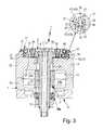
- FIG. 3is a longitudinal section through the rotary drive device of FIG. 1 in a plane offset from FIG. 2 by 90°;
- FIG. 4is a view in perspective, partly in the form of an exploded view, of the rotary drive device of FIGS. 1 through 3 ;
- FIG. 5is a longitudinal section, comparable to FIG. 3 , through a further embodiment of the rotary drive device, equipped with a one-part power takeoff disc.
- the rotary drive deviceidentified overall by reference numeral 1 , has a power takeoff part 4 that can be driven by drive means 2 to a rotary motion about a rotary axis 3 .
- the exemplary embodimentsenable the generation of an oscillating, reciprocating rotary motion, although in principle a design for generating a unidirectional rotary motion, if needed even incremental, would also be possible.
- the power takeoff part 4has a power takeoff disc 5 , which is concentric with the rotary axis 3 and is preferably designed in disklike fashion and on which a component of arbitrary type, not further shown, that can be driven to execute a rotary or pivoting motion can be fixed.
- the power takeoff disc 5is equipped with a suitable fastening interface 6 , which for instance comprises a plurality of fastening holes distributed in a suitable pattern.
- the rotary drive device 1has a device housing 7 , which has a housing wall 8 that demarcates at least one drive chamber 12 that at least partly receives the aforementioned drive means 2 .
- the drive means 2are accommodated in their entirety inside the drive chamber 12 .
- the power takeoff part 4to enable a rotary motion, is rotatably supported on the device housing 7 . With at least part of its length it plunges into the device housing 7 , and it is expediently embodied such that it completely penetrates the device housing 7 —as in the exemplary embodiment. In that case, the power takeoff part 4 also extends into the drive chamber 12 , and for example even through the drive chamber 12 , where it is in rotary driving connection in a suitable way with the drive means 2 .
- the power takeoff part 4has an elongated form and has a longitudinal axis 13 , which when the rotary motion is executed forms the rotary axis 3 .
- the power takeoff part 4includes a power takeoff shaft 14 , which completely or partly penetrates the device housing 7 and which has the power takeoff disc 5 on one of its two end portions.
- the power takeoff disc 5is disposed in the vicinity of an outer side, hereinafter called the front side 15 , of the device housing 7 .
- a rear end portion 16opposite from the power takeoff disc 5 , of the power takeoff shaft 14 protrudes out of the device housing 7 , on a back side 17 thereof opposite from the front side 15 .
- first and second rotary bearing means 18 a , 18 bthe power takeoff part 4 is rotatably supported and axially braced relative to the device housing 7 ; the first rotary bearing means 18 a is disposed in the vicinity of the front side 15 , and the second rotary bearing means 18 b is disposed in the vicinity of the back side 17 . While the first rotary bearing means 18 a is disposed between the power takeoff disc 5 and the housing wall 8 , the second rotary bearing means 18 b are seated between the housing wall 8 and the power takeoff shaft 14 .
- the power takeoff part 4is at the same time braced both radially and axially relative to the device housing 7 .
- the second rotary bearing means 18 bcan thus be limited to radial bracing and are embodied in particular as radial roller bearing means, which concentrically surrounded the power takeoff shaft 14 .
- the drive means 2each include a so-called pivoting piston 22 , which is penetrated in a manner fixed against relative rotation by the power takeoff shaft 14 and has at least one radially protruding pivot vane 23 in sealing contact with the boundary face of the drive chamber 12 .
- the pivoting piston 22could also be embodied in one piece with the power takeoff shaft 14 .
- the pivoting piston 22subdivides the drive chamber 12 into two work compartments 24 a , 24 b , which are each in communication with one of two control conduits 25 a , 25 b , which open out at an outer face of the device housing 7 and through which a controlled action on the two work compartments 24 a , 24 b by fluid is possible, so that the pivoting piston 22 is driven to execute a pivoting motion, from which the rotary motion of the power takeoff part 4 , coupled in motion with the pivoting piston 22 , results.
- the drive means 2include one or two racks, which mesh with a pinion connected to the power takeoff shaft 14 in a manner fixed against relative rotation and which can be driven by fluid action to a linear motion, which is converted by the meshing engagement into a rotary motion of the power takeoff part 4 .
- the driving fluid for the rotary drive device 1compressed air is used in particular, although other gaseous or liquid media are also suitable.
- the drive means 2as electrically actuatable, for instance in the form of an electric servo motor or stepping motor.
- a stop element 25 which goes along with the rotary motioncan be disposed on the rear end portion 16 , protruding from the device housing 7 , of the power takeoff shaft 14 ; with this stop element, the angle of rotation of the power takeoff part 4 can be mechanically limited by cooperation of the stop element with at least one counterpart stop means, not further shown, disposed on the device housing 7 .
- the device housing 7In the vicinity of its front side 15 , the device housing 7 has an axially oriented recess, which will hereinafter be called a bearing receptacle 25 .
- the bearing receptacle 25is open toward the front side 15 of the device housing 7 and is bounded on the back side by a portion, hereinafter called the bottom wall portion 26 , of the housing wall 8 .
- An annular boundary wall portion 27 of the housing wall 8protruding in collarlike fashion toward the front side 15 from the bottom wall portion 26 , delimits the bearing receptacle 25 peripherally, that is, in the radially outer region.
- the bottom wall portion 26is provided with a central aperture 28 , through which the power takeoff shaft 14 extends.
- the power takeoff disc 5With a portion of its axial length, the power takeoff disc 5 is disposed in the bearing receptacle 25 . It protrudes to some extent axially forward out of the bearing receptacle 25 and thus protrudes past the front end face 32 of the boundary wall portion 27 . In a departure from this, the power takeoff disc 5 could also be accommodated sunken entirely in the bearing receptacle 25 .
- the aforementioned first rotary bearing means 18 aare embodied as an annular roller bearing unit 33 , which concentrically surrounds the power takeoff disc 5 .
- the roller bearing unit 33is braced radially inward on the power takeoff disc 5 and radially outward on the inner face of the annular boundary wall portion 27 . Consequently, all the bracing occurs axially inside the bearing receptacle 25 , so that the forces introduced into the power takeoff part 4 can be optimally absorbed by the device housing 7 , even if they are very strong forces. Consequently, the rotary drive device 1 can be used for moving heavy loads, without being subject to particular problems of wear.
- the roller bearing unit 33has a bearing assembly 34 , composed of a plurality of components.
- This bearing assembly 34includes a plurality of individual rolling elements 35 , which in the exemplary embodiment are formed by ball bodies but for instance may also be embodied circular-cylindrically.
- the rolling elements 35are distributed successively along a circular line around the power takeoff disc 5 and are expediently kept at a predetermined spacing from one another by an annular bearing cage 36 that also belongs to the bearing assembly 34 .
- the bearing cage 36may for instance be a striplike element of annular shape that is perforated many times in its circumferential direction, with the perforations forming receiving seats in each of which one rolling element 35 is fixed rotationally movably.
- the bearing cage 36is optional. It can furthermore be realized by still other means as well.
- bearing assembly 34Further components of the bearing assembly 34 are an annular inner running surface arrangement 37 and, with a great diameter than that running surface arrangement, an annular outer running surface arrangement 38 .
- the rolling elements 35rest on these running surface arrangements 37 , 38 and roll on them when the power takeoff part 4 is executing its rotary motion.
- the two running surface arrangements 37 , 38each comprise at least two axially spaced-apart individual running surfaces. These individual running surfaces, viewed in cross section, are disposed in particular in the corner regions of a square, so that each rolling element 35 is braced on four circumferential portions offset from one another by 90°.
- the entire bearing assembly 34is disposed axially inside the bearing receptacle 25 and is surrounded radially on the outside entirely by the boundary wall portion 27 .
- the consequenceis in particular that the entire outer running surface arrangement 38 is surrounded and braced by the boundary wall portion 27 radially delimiting the bearing receptacle 25 on the outside.
- the inner and outer running surface arrangements 37 , 38 in the exemplary embodimentare each formed by a plurality of wirelike bearing rings 42 , 43 .
- the outer running surface arrangement 38is embodied on two outer bearing rings 42 axially spaced apart from one another, which belong to the bearing assembly 34 and are disposed radially between the arrangement of rolling elements 35 and the annular boundary wall portion 27 .
- the outer bearing rings 42are accordingly each braced radially inward on the boundary wall portion 27 and each define one of two outer individual running surfaces that form the outer running surface arrangement 38 .
- an outer annular groove 44 concentric with the power takeoff disc 5is expediently embodied in the radial inner face of the boundary wall portion 27 , and the outer bearing rings 42 are received in this annular groove; one each of the outer bearing rings 42 is braced in one of the two cornerlike transition regions between the groove base and the groove sides of the annular groove 44 .
- the inner running surface arrangement 37expediently also comprises two (inner) individual running surfaces, which are each defined by one of two wirelike inner bearing rings 43 , which are braced, spaced apart axially, radially outward on the power takeoff disc 5 .
- the front inner bearing ring 43 baxially preceding this rear inner bearing ring 43 a , is conversely braced only indirectly on the power takeoff disc 5 , with the interposition of an adjusting ring 45 . This provision makes it possible to adjust the internal prestressing of the bearing assembly 34 and thus the bearing play of the roller bearing unit 33 .
- an adjusting ring 45 that is separate relative to the power takeoff disc 5is screwed concentrically onto the power takeoff disc 5 , for which purpose threaded means 46 in threaded engagement with one another are embodied on the outer circumference of the power takeoff disc 5 and on the inner circumference of the adjusting ring 45 .
- threaded means 46 in threaded engagement with one anotherare embodied on the outer circumference of the power takeoff disc 5 and on the inner circumference of the adjusting ring 45 .
- the relative rotary position between the adjusting ring 45 and the power takeoff disc 5can be secured by means of a securing screw 49 that can be screwed in between these two components.
- the inner bearing rings 43are expediently fixed in a comparable way to the outer bearing rings 42 .
- an inner annular groove 47In the vicinity of the outer circumference of the power takeoff disc 5 , an inner annular groove 47 , open radially outward and partly defined by the adjusting ring 45 and partly by the power takeoff disc 5 , is embodied, in the two corner regions of which one each of the inner bearing rings 43 is braced radially and axially.
- the entire power takeoff part 4is braced in the radial and axial direction and immovably fixed in this way solely by means of the roller bearing unit 33 .
- the adjusting ring 45could also be so joined by other fastening means.
- the adjusting ring 45expediently has a radially outward-protruding annular sealing lip 48 , which goes along with the rotary motion of the power takeoff disc 5 and in the process, in sealing contact, slides along the front end face 32 of the boundary wall portion 27 .
- the boundary wall portion 27is preferably a one-piece component of the housing wall 8 . This ensures especially precise production and bracing.
- the housing wall 8to enable installing the drive means 2 in the vicinity of the drive chamber 12 , is split crosswise.
- the housing wall 8is composed of two wall elements 52 , 53 , disposed in succession in the axial direction of the rotary axis 3 which are joined to one another by fastening elements, especially screws, not further shown.
- the two wall elements 52 , 53thus together define the drive chamber 12 .
- the boundary wall portion 27is disposed on the front one ( 52 ) of the two wall elements and in particular is embodied in one piece with it.
- the two exemplary embodimentsprovide two alternative designs.
- the power takeoff disc 5is embodied in one piece and is also expediently joined integrally to the power takeoff shaft 14 by being made in one piece with it. This variant is recommended above all for rotary drive devices of relatively small structural sizes.
- a power takeoff disc 5split into two parts, which comprises both an annular flange portion 54 , in particular integrally joined in one piece to the power takeoff shaft 14 , and a bearing portion 55 separate from the flange portion but joined to the flange portion 54 in a manner fixed against relative rotation.
- the bearing portion 55is embodied for instance in cup-shaped fashion, so that it fits from the front over the flange portion 54 in hoodlike fashion, as can readily be seen from FIG. 3 .
- the adjusting ring 45here is expediently mounted on the bearing portion 55 , so that the above explanations with regard to the bracing of the inner running surface arrangement 37 apply to the bearing portion 55 as well.
- the bearing portion 55in particular placed coaxially onto the flange portion 54 , can for instance be fixed detachably to the flange portion 54 by means of a plurality of fastening screws 56 .
- the adjusting ring 45is expediently for the most part placed axially in front of the device housing 7 . Only that portion of the adjusting ring 45 on which the front inner bearing ring 43 b is supported plunges into the bearing receptacle 25 , in order to ensure that the bearing assembly 34 is received entirely inside the bearing receptacle 25 .
Landscapes
- Engineering & Computer Science (AREA)
- Physics & Mathematics (AREA)
- Fluid Mechanics (AREA)
- Mechanical Engineering (AREA)
- General Engineering & Computer Science (AREA)
- Rolling Contact Bearings (AREA)
- Reciprocating Pumps (AREA)
Abstract
Description
Claims (17)
Applications Claiming Priority (4)
| Application Number | Priority Date | Filing Date | Title |
|---|---|---|---|
| DEDE102009011764.4 | 2009-03-04 | ||
| DE102009011764 | 2009-03-04 | ||
| DE102009011764ADE102009011764A1 (en) | 2009-03-04 | 2009-03-04 | Rotary drive device |
| PCT/EP2010/000972WO2010099868A1 (en) | 2009-03-04 | 2010-02-17 | Rotary drive device |
Publications (2)
| Publication Number | Publication Date |
|---|---|
| US20110265585A1 US20110265585A1 (en) | 2011-11-03 |
| US8443684B2true US8443684B2 (en) | 2013-05-21 |
Family
ID=42102839
Family Applications (1)
| Application Number | Title | Priority Date | Filing Date |
|---|---|---|---|
| US12/989,990Expired - Fee RelatedUS8443684B2 (en) | 2009-03-04 | 2010-02-17 | Rotary drive device |
Country Status (5)
| Country | Link |
|---|---|
| US (1) | US8443684B2 (en) |
| EP (1) | EP2247860B1 (en) |
| CN (1) | CN102057167A (en) |
| DE (1) | DE102009011764A1 (en) |
| WO (1) | WO2010099868A1 (en) |
Cited By (3)
| Publication number | Priority date | Publication date | Assignee | Title |
|---|---|---|---|---|
| US20180003284A1 (en)* | 2016-07-04 | 2018-01-04 | AUMA Drives GmbH | Drive |
| US10493621B2 (en)* | 2014-08-14 | 2019-12-03 | Knr Systems Inc. | Robot arm having hydraulic rotary actuators |
| US11571807B2 (en) | 2016-10-05 | 2023-02-07 | Robert Darby | Drive unit for robotic manipulators |
Families Citing this family (13)
| Publication number | Priority date | Publication date | Assignee | Title |
|---|---|---|---|---|
| DE102010050612B4 (en) | 2010-11-05 | 2019-10-10 | Festo Ag & Co. Kg | Rotary drive device |
| DE102011107012A1 (en) | 2011-07-09 | 2013-01-10 | Festo Ag & Co. Kg | Rotary drive device for use in motor vehicle-friction clutch, has drive shafts arranged by fluid drive device and electric drive device such that longitudinal axes have same direction as rotation axis of output actuator |
| TWD154404S1 (en) | 2011-09-22 | 2013-07-01 | 菲斯特有限公司 | Engine |
| CN103732926B (en)* | 2011-09-28 | 2016-08-24 | 费斯托股份有限两合公司 | Fluid-actuated rotary drive |
| USD673197S1 (en) | 2012-03-13 | 2012-12-25 | Festo Ag & Co. Kg | Rotary drive device |
| EP2956689B1 (en) | 2013-04-05 | 2016-07-13 | Festo AG & Co. KG | Electrically actuated rotary drive device |
| EP2873871B1 (en)* | 2013-11-14 | 2017-09-13 | FESTO AG & Co. KG | Fluid-actuated rotary drive |
| JP1556890S (en)* | 2015-10-19 | 2016-08-22 | ||
| AU201711756S (en)* | 2016-10-14 | 2017-04-10 | Sew Eurodrive Gmbh & Co | Gearboxes for electric motors and generators |
| WO2022096920A1 (en)* | 2020-11-06 | 2022-05-12 | Mohsen Karimi | Hydraulic and pneumatic rotatory actuator |
| JP1702983S (en)* | 2021-06-01 | 2021-12-27 | ||
| JP1702984S (en)* | 2021-06-01 | 2021-12-27 | ||
| DE202022105571U1 (en)* | 2022-09-30 | 2024-01-04 | Igus Gmbh | Axial-radial plain bearings, especially axial-radial plain bearings for applications with hygiene requirements |
Citations (32)
| Publication number | Priority date | Publication date | Assignee | Title |
|---|---|---|---|---|
| US2220027A (en)* | 1939-07-06 | 1940-10-29 | Dorr Co Inc | Annular thrust bearing |
| US2781027A (en)* | 1955-07-27 | 1957-02-12 | Control Specialists Inc | Rotary actuating device |
| US2796776A (en)* | 1952-06-04 | 1957-06-25 | Locke Sr | Indexing table |
| US3002429A (en)* | 1956-08-11 | 1961-10-03 | Rothe Erde Eisenwerk | Bearing arrangement for supporting a rotatable element of a machine tool or the like |
| US3099073A (en)* | 1961-10-02 | 1963-07-30 | Keystone Engineering Company | Method of making anti-friction bearing assembly |
| US3148595A (en)* | 1963-05-21 | 1964-09-15 | Ohio Oscillator Company | Fluid motor actuator |
| US3482892A (en)* | 1967-04-15 | 1969-12-09 | Rothe Erde Eisenwerk | Antifriction bearing |
| US3543367A (en)* | 1968-01-29 | 1970-12-01 | Alfred E R Arnot | Wire race ball bearing manufacture |
| US4070935A (en)* | 1976-04-09 | 1978-01-31 | Forkardt, Gefitec | Chucking device for a machine tool |
| US4508016A (en)* | 1983-09-09 | 1985-04-02 | Weyer Paul P | Rotary actuated support |
| US4509871A (en)* | 1982-11-30 | 1985-04-09 | Carl-Zeiss-Stiftung, Heidenheim/Brenz | Play-free anti-friction bearing construction |
| US4688953A (en)* | 1983-12-20 | 1987-08-25 | Ina Bearing Company, Inc. | Bearing race manufactured from preprofiled wire |
| US4696586A (en)* | 1984-10-04 | 1987-09-29 | Hoesch Aktiengesellschaft | Wire roll bearing |
| US4778287A (en)* | 1986-04-21 | 1988-10-18 | Hoesch Aktiengesellschaft | Annular multi-row bearing with shaped-wire races |
| US4784047A (en)* | 1984-10-13 | 1988-11-15 | Kurt Stoll | Oscillating piston motor |
| US4797008A (en)* | 1985-04-09 | 1989-01-10 | Franke & Heydrich Kg | Roller bearing for rotary or linear applications |
| US5493876A (en)* | 1993-01-12 | 1996-02-27 | Precision Fukuhara Works, Ltd. | Circular knitting machine and bearing assembly for same |
| DE19511488A1 (en) | 1995-03-29 | 1996-10-02 | Festo Kg | Oscillating piston fluid-driven motor |
| US5834662A (en)* | 1993-06-19 | 1998-11-10 | Imo-Industrie-Momentenlager Stoll & Russ Gmbh | Arrangement for the rotary actuation of an apparatus on a chassis or foundation |
| US6003431A (en)* | 1998-04-14 | 1999-12-21 | Bertini; Millo | Rotary actuator |
| US6170384B1 (en)* | 1998-01-31 | 2001-01-09 | Festo Ag & Co. | Fluid power rotary drive device |
| US6269664B1 (en)* | 2001-01-24 | 2001-08-07 | Pai Lung Machinery Mill Co., Ltd. | Adjustment structure of press ring and steel ring for circular knitting machine |
| CN1311399A (en) | 2000-03-03 | 2001-09-05 | 速睦喜股份有限公司 | Rotation apparatus with buffer mechanism |
| JP2002130208A (en) | 2000-10-30 | 2002-05-09 | Koganei Corp | Oscillating actuator |
| CN1603636A (en) | 2003-10-04 | 2005-04-06 | 费斯托合资公司 | Fluid-actuated rotary drive |
| EP1591194A2 (en) | 2004-04-28 | 2005-11-02 | Sankyo Seisakusho Co. | Machine tool with detachable/attachable motor for driving a rotating table |
| CN1742175A (en) | 2002-11-25 | 2006-03-01 | 德尔伯特·特萨 | Standard Rotary Actuator |
| JP2007127160A (en) | 2005-11-01 | 2007-05-24 | Koganei Corp | Rotary actuator |
| US20070116394A1 (en)* | 2005-11-22 | 2007-05-24 | Thyssenkrupp - Rotek, Inc. | Slewing ring having improved inner race construction |
| DE102006015478A1 (en) | 2006-04-03 | 2007-10-11 | Franke & Heydrich Kg | Antifriction bearing for use in form of e.g. linear guide, has running wire bed with longitudinal recess, and damping bar with side pointing to running wire and forming pressure surface that protrudes in unloaded condition over bed outline |
| WO2008075481A1 (en) | 2006-12-21 | 2008-06-26 | Koganei Corporation | Rotary actuator |
| US20090205486A1 (en)* | 2006-03-31 | 2009-08-20 | Christian Ante | Fluid Operated Rotary Drive |
- 2009
- 2009-03-04DEDE102009011764Apatent/DE102009011764A1/ennot_activeWithdrawn
- 2010
- 2010-02-17CNCN2010800017604Apatent/CN102057167A/enactivePending
- 2010-02-17WOPCT/EP2010/000972patent/WO2010099868A1/enactiveApplication Filing
- 2010-02-17USUS12/989,990patent/US8443684B2/ennot_activeExpired - Fee Related
- 2010-02-17EPEP10704761.5Apatent/EP2247860B1/enactiveActive
Patent Citations (37)
| Publication number | Priority date | Publication date | Assignee | Title |
|---|---|---|---|---|
| US2220027A (en)* | 1939-07-06 | 1940-10-29 | Dorr Co Inc | Annular thrust bearing |
| US2796776A (en)* | 1952-06-04 | 1957-06-25 | Locke Sr | Indexing table |
| US2781027A (en)* | 1955-07-27 | 1957-02-12 | Control Specialists Inc | Rotary actuating device |
| US3002429A (en)* | 1956-08-11 | 1961-10-03 | Rothe Erde Eisenwerk | Bearing arrangement for supporting a rotatable element of a machine tool or the like |
| US3099073A (en)* | 1961-10-02 | 1963-07-30 | Keystone Engineering Company | Method of making anti-friction bearing assembly |
| US3148595A (en)* | 1963-05-21 | 1964-09-15 | Ohio Oscillator Company | Fluid motor actuator |
| US3482892A (en)* | 1967-04-15 | 1969-12-09 | Rothe Erde Eisenwerk | Antifriction bearing |
| US3543367A (en)* | 1968-01-29 | 1970-12-01 | Alfred E R Arnot | Wire race ball bearing manufacture |
| US4070935A (en)* | 1976-04-09 | 1978-01-31 | Forkardt, Gefitec | Chucking device for a machine tool |
| US4509871A (en)* | 1982-11-30 | 1985-04-09 | Carl-Zeiss-Stiftung, Heidenheim/Brenz | Play-free anti-friction bearing construction |
| US4508016A (en)* | 1983-09-09 | 1985-04-02 | Weyer Paul P | Rotary actuated support |
| US4688953A (en)* | 1983-12-20 | 1987-08-25 | Ina Bearing Company, Inc. | Bearing race manufactured from preprofiled wire |
| US4696586A (en)* | 1984-10-04 | 1987-09-29 | Hoesch Aktiengesellschaft | Wire roll bearing |
| US4784047A (en)* | 1984-10-13 | 1988-11-15 | Kurt Stoll | Oscillating piston motor |
| US4797008A (en)* | 1985-04-09 | 1989-01-10 | Franke & Heydrich Kg | Roller bearing for rotary or linear applications |
| US4778287A (en)* | 1986-04-21 | 1988-10-18 | Hoesch Aktiengesellschaft | Annular multi-row bearing with shaped-wire races |
| US5493876A (en)* | 1993-01-12 | 1996-02-27 | Precision Fukuhara Works, Ltd. | Circular knitting machine and bearing assembly for same |
| US5834662A (en)* | 1993-06-19 | 1998-11-10 | Imo-Industrie-Momentenlager Stoll & Russ Gmbh | Arrangement for the rotary actuation of an apparatus on a chassis or foundation |
| DE19511488A1 (en) | 1995-03-29 | 1996-10-02 | Festo Kg | Oscillating piston fluid-driven motor |
| US6170384B1 (en)* | 1998-01-31 | 2001-01-09 | Festo Ag & Co. | Fluid power rotary drive device |
| US6003431A (en)* | 1998-04-14 | 1999-12-21 | Bertini; Millo | Rotary actuator |
| CN1311399A (en) | 2000-03-03 | 2001-09-05 | 速睦喜股份有限公司 | Rotation apparatus with buffer mechanism |
| US6497172B2 (en) | 2000-03-03 | 2002-12-24 | Smc Corporation | Rotary actuator with cushion mechanism |
| JP2002130208A (en) | 2000-10-30 | 2002-05-09 | Koganei Corp | Oscillating actuator |
| US6269664B1 (en)* | 2001-01-24 | 2001-08-07 | Pai Lung Machinery Mill Co., Ltd. | Adjustment structure of press ring and steel ring for circular knitting machine |
| US7081062B2 (en) | 2002-11-25 | 2006-07-25 | Delbert Tesar | Standardized rotary actuator |
| CN1742175A (en) | 2002-11-25 | 2006-03-01 | 德尔伯特·特萨 | Standard Rotary Actuator |
| CN1603636A (en) | 2003-10-04 | 2005-04-06 | 费斯托合资公司 | Fluid-actuated rotary drive |
| EP1591194A2 (en) | 2004-04-28 | 2005-11-02 | Sankyo Seisakusho Co. | Machine tool with detachable/attachable motor for driving a rotating table |
| JP2007127160A (en) | 2005-11-01 | 2007-05-24 | Koganei Corp | Rotary actuator |
| US20070116394A1 (en)* | 2005-11-22 | 2007-05-24 | Thyssenkrupp - Rotek, Inc. | Slewing ring having improved inner race construction |
| US20090205486A1 (en)* | 2006-03-31 | 2009-08-20 | Christian Ante | Fluid Operated Rotary Drive |
| US7739944B2 (en)* | 2006-03-31 | 2010-06-22 | Festo Ag & Co. Kg | Fluid operated rotary drive |
| DE102006015478A1 (en) | 2006-04-03 | 2007-10-11 | Franke & Heydrich Kg | Antifriction bearing for use in form of e.g. linear guide, has running wire bed with longitudinal recess, and damping bar with side pointing to running wire and forming pressure surface that protrudes in unloaded condition over bed outline |
| WO2008075481A1 (en) | 2006-12-21 | 2008-06-26 | Koganei Corporation | Rotary actuator |
| JP2008157289A (en) | 2006-12-21 | 2008-07-10 | Koganei Corp | Rotary actuator |
| EP2093432A1 (en) | 2006-12-21 | 2009-08-26 | Koganei Corporation | Rotary actuator |
Cited By (4)
| Publication number | Priority date | Publication date | Assignee | Title |
|---|---|---|---|---|
| US10493621B2 (en)* | 2014-08-14 | 2019-12-03 | Knr Systems Inc. | Robot arm having hydraulic rotary actuators |
| US20180003284A1 (en)* | 2016-07-04 | 2018-01-04 | AUMA Drives GmbH | Drive |
| US10788117B2 (en)* | 2016-07-04 | 2020-09-29 | AUMA Drives GmbH | Drive |
| US11571807B2 (en) | 2016-10-05 | 2023-02-07 | Robert Darby | Drive unit for robotic manipulators |
Also Published As
| Publication number | Publication date |
|---|---|
| EP2247860A1 (en) | 2010-11-10 |
| DE102009011764A1 (en) | 2010-09-09 |
| EP2247860B1 (en) | 2016-04-20 |
| CN102057167A (en) | 2011-05-11 |
| WO2010099868A1 (en) | 2010-09-10 |
| US20110265585A1 (en) | 2011-11-03 |
Similar Documents
| Publication | Publication Date | Title |
|---|---|---|
| US8443684B2 (en) | Rotary drive device | |
| JP4994020B2 (en) | Rotary actuator | |
| KR20180112041A (en) | Braking device for a hydraulic automotive braking system having a ball screw drive | |
| US10090730B2 (en) | Linear actuator | |
| EP3073113B1 (en) | Diaphragm pump | |
| KR20010049247A (en) | Driving unit of a welding equipment | |
| US10371155B2 (en) | Fan assembly having a rotatingly drive hub | |
| KR101607093B1 (en) | Device for mounting a linear drive | |
| KR101367533B1 (en) | Gear pump, especially for a power steering system | |
| US20120199412A1 (en) | Ball Screw And Steering Device Equipped With The Same | |
| JP2015061334A (en) | Linear actuator | |
| US8581527B2 (en) | Mechanism for converting rotary motion into linear motion and lifting device | |
| JP2000220715A (en) | Linear actuator | |
| KR20070064253A (en) | Axial fan and blade assembly method with variable blade | |
| US4500805A (en) | Electromechanical linear actuator | |
| KR101458359B1 (en) | Servo press apparatus | |
| US5957029A (en) | Linear thruster | |
| EP2982569B1 (en) | Rack guide device and steering apparatus including same | |
| CN213684518U (en) | Compressor | |
| US20020100362A1 (en) | Actuator | |
| JP3729724B2 (en) | Oscillating actuator | |
| KR102488782B1 (en) | Gearbox and actuator having the same | |
| KR20180024586A (en) | Suspension system | |
| JP2008045646A (en) | Fluid-pressure actuator | |
| CN220764355U (en) | Vehicle brake system |
Legal Events
| Date | Code | Title | Description |
|---|---|---|---|
| AS | Assignment | Owner name:FESTO AG & CO. KG, GERMANY Free format text:ASSIGNMENT OF ASSIGNORS INTEREST;ASSIGNORS:THORWART, GERHARD;ARMBRUSTER, RAINER;REEL/FRAME:025211/0575 Effective date:20100629 | |
| FEPP | Fee payment procedure | Free format text:PAYOR NUMBER ASSIGNED (ORIGINAL EVENT CODE: ASPN); ENTITY STATUS OF PATENT OWNER: LARGE ENTITY | |
| STCF | Information on status: patent grant | Free format text:PATENTED CASE | |
| CC | Certificate of correction | ||
| FPAY | Fee payment | Year of fee payment:4 | |
| AS | Assignment | Owner name:FESTO SE & CO. KG, GERMANY Free format text:CHANGE OF NAME;ASSIGNOR:FESTO AG & CO. KG;REEL/FRAME:052136/0406 Effective date:20200131 | |
| MAFP | Maintenance fee payment | Free format text:PAYMENT OF MAINTENANCE FEE, 8TH YEAR, LARGE ENTITY (ORIGINAL EVENT CODE: M1552); ENTITY STATUS OF PATENT OWNER: LARGE ENTITY Year of fee payment:8 | |
| FEPP | Fee payment procedure | Free format text:MAINTENANCE FEE REMINDER MAILED (ORIGINAL EVENT CODE: REM.); ENTITY STATUS OF PATENT OWNER: LARGE ENTITY | |
| LAPS | Lapse for failure to pay maintenance fees | Free format text:PATENT EXPIRED FOR FAILURE TO PAY MAINTENANCE FEES (ORIGINAL EVENT CODE: EXP.); ENTITY STATUS OF PATENT OWNER: LARGE ENTITY | |
| STCH | Information on status: patent discontinuation | Free format text:PATENT EXPIRED DUE TO NONPAYMENT OF MAINTENANCE FEES UNDER 37 CFR 1.362 | |
| FP | Lapsed due to failure to pay maintenance fee | Effective date:20250521 |