US8443610B2 - Low emission gas turbine combustor - Google Patents
Low emission gas turbine combustorDownload PDFInfo
- Publication number
- US8443610B2 US8443610B2US12/625,750US62575009AUS8443610B2US 8443610 B2US8443610 B2US 8443610B2US 62575009 AUS62575009 AUS 62575009AUS 8443610 B2US8443610 B2US 8443610B2
- Authority
- US
- United States
- Prior art keywords
- liner
- aft
- outboard
- section
- inboard
- Prior art date
- Legal status (The legal status is an assumption and is not a legal conclusion. Google has not performed a legal analysis and makes no representation as to the accuracy of the status listed.)
- Active, expires
Links
Images

Classifications
- F—MECHANICAL ENGINEERING; LIGHTING; HEATING; WEAPONS; BLASTING
- F23—COMBUSTION APPARATUS; COMBUSTION PROCESSES
- F23R—GENERATING COMBUSTION PRODUCTS OF HIGH PRESSURE OR HIGH VELOCITY, e.g. GAS-TURBINE COMBUSTION CHAMBERS
- F23R3/00—Continuous combustion chambers using liquid or gaseous fuel
- F23R3/42—Continuous combustion chambers using liquid or gaseous fuel characterised by the arrangement or form of the flame tubes or combustion chambers
- F23R3/50—Combustion chambers comprising an annular flame tube within an annular casing
- F—MECHANICAL ENGINEERING; LIGHTING; HEATING; WEAPONS; BLASTING
- F23—COMBUSTION APPARATUS; COMBUSTION PROCESSES
- F23R—GENERATING COMBUSTION PRODUCTS OF HIGH PRESSURE OR HIGH VELOCITY, e.g. GAS-TURBINE COMBUSTION CHAMBERS
- F23R3/00—Continuous combustion chambers using liquid or gaseous fuel
- F23R3/02—Continuous combustion chambers using liquid or gaseous fuel characterised by the air-flow or gas-flow configuration
- F23R3/04—Air inlet arrangements
- F23R3/06—Arrangement of apertures along the flame tube
- Y—GENERAL TAGGING OF NEW TECHNOLOGICAL DEVELOPMENTS; GENERAL TAGGING OF CROSS-SECTIONAL TECHNOLOGIES SPANNING OVER SEVERAL SECTIONS OF THE IPC; TECHNICAL SUBJECTS COVERED BY FORMER USPC CROSS-REFERENCE ART COLLECTIONS [XRACs] AND DIGESTS
- Y02—TECHNOLOGIES OR APPLICATIONS FOR MITIGATION OR ADAPTATION AGAINST CLIMATE CHANGE
- Y02T—CLIMATE CHANGE MITIGATION TECHNOLOGIES RELATED TO TRANSPORTATION
- Y02T50/00—Aeronautics or air transport
- Y02T50/60—Efficient propulsion technologies, e.g. for aircraft
Definitions
- This inventionrelates generally to gas turbine engines and, more particularly, to combustors for gas turbine engines.
- Gas turbine enginessuch as those used to power modern commercial aircraft or in industrial applications, include a compressor for pressurizing a supply of air, a combustor for burning a hydrocarbon fuel in the presence of the pressurized air, and a turbine for extracting energy from the resultant combustion gases.
- the compressor, combustor and turbineare disposed about a central engine axis with the compressor disposed axially upstream of the combustor and the turbine disposed axially downstream of the combustor.
- An exemplary combustorfeatures an annular combustion chamber defined between a radially inboard liner and a radially outboard liner extending aft from a forward bulkhead.
- the radially outboard linerextends circumferentially about and is radially spaced from the inboard liner, with the combustion chamber extending fore to aft therebetween.
- Exemplary linersare double structured, having an inner heat shield and an outer shell. Arrays of circumferentially distributed combustion air holes penetrate the outboard liner and the inboard liner at one or more axial locations to admit combustion air into the combustion chamber along the length of the combustion chamber.
- a plurality of circumferentially distributed fuel injectors and associated swirlers or air passagesis mounted in the forward bulkhead.
- the fuel injectorsproject into the forward end of the combustion chamber to supply the fuel.
- the swirlersimpart a swirl to inlet air entering the forward end of the combustion chamber at the bulkhead to provide rapid mixing of the fuel and inlet air.
- NOx emissionsare the subject of increasingly stringent controls by regulatory authorities.
- One combustion strategy for minimizing NOx emissions from gas turbine enginesis referred to as rich burn, quick quench, lean burn (RQL) combustion.
- RQL combustion strategyrecognizes that the conditions for NOx formation are most favorable at elevated combustion flame temperatures, i.e. when the fuel-air ratio is at or near stoichiometric.
- the combustion processat least during operation at or near full power, includes three serially arranged combustion zones: a fuel-rich combustion zone at the forward end of the combustor, a quench or dilution zone that involves the transition from fuel-rich combustion to fuel-lean combustion via the addition of combustion air, and a lean combustion zone axially aft of the quench or dilution zone.
- the combustion process in a combustor configured for RQL combustionhas two governing states of combustion: a first state in the forward portion of the combustor that is stoichiometrically fuel-rich and a second state in a downstream portion of the combustor that is stoichiometrically fuel-lean.
- An annular combustor for a gas turbine engineincludes an inboard liner extending longitudinally fore-to-aft and having a forward section and an aft section, an outboard liner spaced radially outboard of and generally coaxially circumscribing the inboard liner and having a forward section and an aft section, and a bulkhead extending between a forward end of the inboard liner and a forward end of the outboard liner and cooperating therewith to define a combustor interior volume extending fore to aft from the bulkhead to an annular combustor exit extending between the aft end of the inboard liner and the aft end of the outboard liner.
- a plurality of combustion air admission holesare formed in each of the inboard liner and the outboard liner.
- the plurality of combustion air admission holesare arranged with the respective centers of the plurality of combustion air admission holes disposed in a circumferential row.
- the combustor interior volumeincludes a forward volume extending fore to aft from the bulkhead to an annular boundary extending between the aft end of the forward section of the inboard liner and the aft end of the forward section of the outboard liner, an aft volume extending fore to aft from an annular boundary extending between the centers of the row combustion air admission holes in the inboard liner and the centers of the row of combustion air admission holes in the outboard liner and the annular combustor exit, and an intermediate volume extending fore to aft from a forward end interfacing with an aft end of the forward volume to an aft end interfacing with a forward end of the aft volume.
- the forward volumerepresents from about 30% to about 40% of the combustor interior volume
- the intermediate volumerepresents from about 10% to about 20% of the combustor interior volume
- the aft volumerepresents from about 40% to about 60% of the combustor interior volume.
- the forward volumerepresents about 35% of the combustor interior volume
- the intermediate volumerepresents about 20% of the combustor interior volume
- the aft volumerepresents about 45% of the combustor interior volume.
- the forward section of the inboard liner and the forward section of the outboard linerconverge from fore to aft.
- the forward section of the inboard linerconverges toward the forward section of the outboard liner at an included interior angle in the range of from 70 degrees to 85 degrees and the forward section of the outboard liner converges toward the forward section of the inboard liner at an included interior angle in the range of from 70 degrees to 85 degrees.
- the forward section of the inboard linerconverges toward the forward section of the outboard liner at an included interior angle in the range of from 74 degrees to 78 degrees.
- the forward section of the outboard linerconverges toward the forward section of the inboard liner at an included interior angle in the range of from 74 degrees to 78 degrees.
- the aft section of the inboard linerextends aftwardly from the aft end of the forward section of the inboard liner at an angle in the range of from 180 degrees to 200 degrees and the aft section of the outboard liner extends aftwardly from the aft end of the forward section of the outboard liner at an angle in the range of from 180 degrees to 200 degrees.
- the aft section of the inboard linerextends aftwardly from the aft end of the forward section of the inboard liner at an angle in the range of from 188 degrees to 192 degrees.
- the aft section of the outboard linerextends aftwardly from the aft end of the forward section of the outboard liner at an angle in the range of from 190 degrees to 196 degrees.
- the annular combustorincludes a plurality of fuel injectors mounted in the bulkhead, the fuel injectors disposed in a circumferential array at equally spaced circumferential intervals, S, center-to-center.
- the fuel injectorsmay be spaced such that a ratio S/D has a value in the range of at least 1.1 to not greater than 1.30, D being the annular depth in a radial direction of the combustor interior volume between the inboard liner and the outboard liner at the interface of the intermediate volume with the aft volume.
- the fuel injectorsmay be spaced such that the ratio S/D has a value in the range of 1.25 to 1.30.
- the fuel injectorsmay also be spaced such that the ratio S/H has a value in the range of at least 0.9 to less than 0.95, H being the annular height in a radial direction of the bulkhead extending between the forward end of the inboard liner and the forward end of the outboard liner.
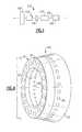
- FIG. 1is a schematic representation of a gas turbine engine
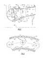
- FIG. 2is a sectioned side elevation view of an annular combustor according to the present invention.
- FIG. 3is a sectioned elevation view taken substantially along line 3 - 3 of FIG. 2 ;
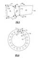
- FIG. 4is a perspective view showing an annular combustor according to the invention.
- FIG. 5is a simplified line drawing of the side elevation view of the annular combustor of FIG. 2 illustrating certain dimensional and angular relationships;
- FIG. 6is a simplified line drawing of an elevation view of the combustor shown in FIG. 4 taken substantially in the direction of line 5 - 5 .
- FIG. 1there is depicted schematically a conventional gas turbine engine 102 including a combustor module 110 , a compressor 120 disposed forward, that is upstream with respect to flow, of the combustor module 110 , a diffuser 140 extending from the outlet of the compressor to the forward end of the combustor module 110 , and a turbine module 160 disposed aft, that is downstream with respect to flow, of the combustor module 110 .
- the compressor, combustion module and turbine moduleare generally coaxially disposed about a central axis 150 of the engine shaft which constitutes the centerline of the gas turbine engine.
- a large diameter fan 108is mounted to the engine shaft forward of the compressor 120 .
- the exemplary combustor moduleincludes an annular combustor 100 which is disposed concentric with the engine axis 150 in an annular pressure vessel (not shown) defined by a radially inner case (not shown) and a radially outer case (not shown).
- the annular combustorincludes a radially inboard liner 32 , a radially outboard liner 34 that circumscribes the inboard liner 32 , and a forward bulkhead 36 .
- the inboard liner 32has a forward section 31 and an aft section 33 and extends longitudinally fore-to-aft from a forward end of the forward section 31 to an aft end of the aft section 33 .
- the outboard liner 34has a forward section 37 and an aft section 39 and extends longitudinally fore-to-aft from a forward end of the forward section 37 to an aft end of the aft section 39 .
- the bulkhead 36extends between the respective forward end of the forward section 31 of the inboard liner 32 and the forward end of the forward section 37 of the outboard liner 34 .
- the inboard liner 32 , the outboard liner 34 and the forward bulkhead 36bound the annular combustion chamber 30 and define a combustor interior volume that extends longitudinally within the annulus formed by the inboard liner 32 and the outboard liner 34 from the bulkhead 36 to an annular combustor exit extending between the respective aft ends of the respective aft sections, 33 , 39 of the inner and outboard liners 32 , 34 .
- the forward bulkhead 36carries a plurality of fuel injectors 40 , for example typically from 12 to 24 depending upon the size of the engine, disposed in a circumferential array at spaced intervals about the annular combustion chamber 30 .
- Each fuel nozzle 40is disposed at the end of a fuel injector 38 which extends through the outer case (not shown) to convey fuel from an external source to the associated fuel nozzle.
- Each fuel nozzle 40injects fuel through a spray head into a central stream of air emitted along the centerline of the fuel nozzle.
- An air passage 41which may have a swirler 42 associated therewith as depicted in the exemplary embodiment, is operatively associated with each fuel nozzle 40 .
- pressurized air from the compressoris decelerated as it passes through the diffuser and is directed into the annular plenums 90 , 92 defined within the annular pressure vessel (not shown), the annular plenum 90 extending circumferentially along and radially inwardly of the inboard liner 32 and the annular plenum 92 extending circumferentially about and radially outwardly of the outboard liner 34 .
- a portion of this pressured airpasses into the combustion chamber 30 through the air passages 41 .
- Each swirler 42imparts a spin to the air passing therethrough to provide rapid mixing of this air with the fuel being injected through the associated fuel nozzle 40 to promote initial combustion of the fuel in a fuel-rich state in a forward portion of the combustion chamber 30 .
- the inboard liner 32 and the outboard liner 34are each of a double-wall construction. More specifically, the inboard liner 32 and the outboard liner 34 are each structured with a support shell and associated forward and aft heat shields secured, respectively, to forward and aft portions of the support shell.
- the inboard liner 32includes a single piece inner support shell 58 , a forward heat shield 60 secured by fasteners (not shown) to the forward portion of the support shell 58 and an aft heat shield 62 secured by fasteners (not shown) to the aft portion of the support shell 58 .
- the outboard liner 34includes a single piece outer support shell 44 , a forward heat shield 46 secured by fasteners (not shown) to the forward portion of the support shell 44 , and an aft heat shield 48 secured by fasteners (not shown) to the aft portion of the support shell 44 .
- the heat shieldsmay be formed as a circumferential array of panels, each panel having a longitudinal expanse in the axial direction and a lateral expanse in the circumferential direction. Each heat shield panel has a longitudinal expanse in the axial direction, a lateral expanse in the circumferential direction, and a surface that faces the hot combustion products within the combustion chamber 30 .
- Exemplary liner and heat shield constructionsare described and shown in commonly assigned U.S. Pat. No. 7,093,439, the entire disclosure of which is hereby incorporated herein by reference as if set forth herein.
- Other embodiments, including single-wall liners,are still within the spirit and scope of the invention.
- this pressurized airenters the forward region of the combustion chamber 30 through the fuel injectors 40 and by way of the air passages 41 associated the fuel injectors 40 .
- Additional airenters the forward region of the combustion chamber 30 by way of cooling holes (not shown) in the forward bulkhead 36 as bulkhead cooling air.
- Another portion of pressurized air from the annular plenums 90 , 92enters the combustion chamber 30 through a plurality of combustion air admission holes 66 , 68 as combustion air for the purpose of contributing to the combustion process, diluting the combustion products and reducing hot spots within the combustion products to provide a desired spatial temperature profile across the combustion products before entering the turbine module 16 .
- the combustion air admission holes 66 , 68are formed in the aft heat shields of the inner and outboard liners 32 , 34 , respectively.
- Each of the combustion air admission holes 66 in the inboard liner 32is formed by corresponding aligned holes formed in the aft portion of the support shell 58 and the associated aft heat shield 62 .
- the plurality of combustion air admission holes 66 in the inboard liner 32are arranged in spaced relationship with the respective centers of the plurality of combustion air admission holes 66 disposed in a circumferential row.
- each of the combustion air admission holes 68 in the outboard liner 34is formed by corresponding aligned holes formed in the aft portion of the support shell 44 and the associated aft heat shield 48 .
- the plurality of combustion air admission holes 68 in the outboard liner 34are also arranged in spaced relationship with the respective centers of the plurality of combustion air admission holes 68 disposed in a circumferential row.
- a single row of uniformly sized combustion air admission holes 66 , 68are provided in the inner and outer liners 32 , 34 , respectively.
- other arrangements of combustion air admission holesmay be used, for example a single row of alternating relatively larger and relatively smaller combustion air admission holes may be provided in either or both of the inner and outer liners 32 , 34 .
- the interior volume of the combustion chamber 30consists of a forward volume, V 1 , an intermediate volume, V 2 , and an aft volume, V 3 .
- the forward volume, V 1extends longitudinally fore to aft from the bulkhead 36 to an annular boundary, P 1 , extending between the aft end of the forward section of the inboard liner 32 and the aft end of the forward section of the outboard liner 34
- the aft volume, V 3extends longitudinally fore to aft from an annular boundary, P 2 , extending between the centers of the row of combustion air admission holes 66 in the inboard liner 32 and the centers of the row of combustion air admission holes 68 in the outboard liner 34 and the annular combustor exit boundary, P 3 .
- the intermediate volume, V 2extends longitudinally fore to aft from a forward end interfacing with an aft end of the forward volume, V 1 , to an aft end interfacing with a forward end of the aft volume, V 3 .
- the forward volume, V 1represents from about 30% to about 40% of the combustor interior volume
- the intermediate volume, V 2represents from about 10% to about 20% of the combustor interior volume
- the aft volume, V 3represents from about 40% to about 60% of the combustor interior volume.
- the forward volume, V 1represents about 35% of the combustor interior volume
- the intermediate volume, V 2represents about 20% of the combustor interior volume
- the aft volume, V 3represents about 45% of the combustor interior volume.
- the combustion chamber 30has a forward portion wherein the inboard liner 32 and outboard liner 34 converge from fore to aft and an aft portion wherein the inboard inner 32 and outboard liner 34 converge fore to aft more gradually in comparison to the forward portion, such as depicted in FIGS. 2 and 5 , or extend in parallel relationship.
- the converging forward portion of the combustion chamber 30is bounded by and is coextensive with the forward section 31 of the inboard liner 32 and the forward section 37 of the outboard liner 34 .
- the converging forward portion of the combustion chamber 30is commensurate with and encompasses the forward volume, V 1 , of the combustor interior volume.
- the aft portion of the combustion chamber 30is bounded by and is coextensive with the aft section 33 of the inboard liner 32 and the aft section 39 of the outboard liner 34 .
- the aft portion of the combustion chamber 30is commensurate with and encompasses both the intermediate volume, V 2 , and the aft volume, V 3 .
- the forward section 31 of the inboard liner 32converges inwardly toward the forward section 37 of the outboard liner 34 at an interior angle, ⁇ 1 , with the bulkhead 36 in the range of from 70 degrees to 85 degrees and the forward section 37 of the outboard liner 34 also converges inwardly toward the forward section 31 of the inboard liner 32 at an interior angle, ⁇ 2 , with the bulkhead 36 in the range of from 70 degrees to 85 degrees.
- the forward section 31 of the inboard liner 32converges toward the forward section 37 of the outboard liner 34 at an interior angle, ⁇ 1 , with the bulkhead 36 in the range of from 74 degrees to 78 degrees.
- the forward section 37 of the outboard liner 34converges toward the forward section 31 of the inboard liner 32 at an interior angle, ⁇ 2 , with the bulkhead 36 in the range of from 74 degrees to 78 degrees.
- the aft section 33 of the inboard liner 32extends aftwardly from the aft end of the forward section 31 of the inboard liner 32 at an angle, ⁇ 3 , in the range of from 180 degrees to 200 degrees and the aft section 39 of the outboard liner 34 extends aftwardly from the aft end of the forward section 37 of the outboard liner 34 at an angle, ⁇ 4 , in the range of from 180 degrees to 200 degrees.
- the aft section 33 of the inboard liner 32extends aftwardly from the aft end of the forward section 31 of the inboard liner 32 at an angle, ⁇ 3 , in the range of from 188 degrees to 192 degrees.
- the aft section 39 of the outboard liner 34extends aftwardly from the aft end of the forward section 37 of the outboard liner 34 at an angle, ⁇ 4 , in the range of from 190 degrees to 196 degrees.
- the annular combustor 100includes a plurality of fuel injectors 40 mounted in the bulkhead 36 .
- the fuel injectors 40are disposed in a circumferential array at equally spaced circumferential intervals, S, around the bulkhead 36 as illustrated in FIG. 6 .
- the fuel injectors 40may be spaced such that a ratio S/D has a value in the range of at least 1.1 to not greater than 1.30, wherein D is the annular depth in a radial direction of the combustor interior volume between the inboard liner 32 and the outboard liner 34 at the interface of the intermediate volume, V 2 , with the aft volume, V 3 .
- the interface of the intermediate volume, V 2 , with the aft volume, V 3 ,is coincident with the annular boundary, P 2 , extending between the centers of the row of combustion air admission holes 66 in the inboard liner 32 and the centers of the row of combustion air admission holes 68 in the outboard liner 34 .
- the fuel injectors 40may be spaced apart such that the ratio S/D has a value in the range of 1.25 to 1.30.
- the fuel injectorsmay also be spaced apart such that the ratio S/H also has a value in the range of at least 0.9 to less than 0.95, H being the annular height in a radial direction of the bulkhead 36 extending between the forward end of the inboard liner 32 and the forward end of the outboard liner 34 .
- the annular combustor 100 described hereinmay be operated as a low NO X emission combustor via a combustion process commonly referred to as “rich burn-quick quench-lean burn” (RQL) combustion.
- RQL combustionthe portion of the combustion air admitted to the combustion chamber as primary air is limited to an amount significantly less than the amount of air required for stoichiometric combustion of the fuel injected through the fuel injectors 40 .
- combustion in the combustion chamber upstream of the admission of additional combustion air through the plurality of combustion air admission nozzles 66 , 68occurs, on average, under fuel rich conditions, although local variability in terms of stoichiometric combustion is likely.
- the overall fuel-rich stoichiometry of the fuel-air mixture in this rich burn zoneproduces a relatively cool flame, thus reducing excessive NOx formation and guarding against blowout of the combustion flame during any abrupt reduction in engine power or low-power operation.
- the combustion products from this rich burn zonewhich include unburned fuel, then enter a quench zone commensurate with the region of the combustion chamber 30 into which the additional combustion air is admitted through the aforementioned combustion air admission holes 66 , 68 to penetrate radially inwardly into the combustion products to dilute and derich the combustion products from their stoichiometrically rich state proximate to the forward edge of the quench zone to a stoichiometrically fuel lean state proximate to the aft edge of the quench zone.
- the combustion processis substantially completed under fuel lean conditions in the lean zone that extends from the aft extent of the quench zone longitudinally aftward to the annular combustor exit.
- combustion within the forward volume, V 1 , of the interior volume of the combustion chamber 30 of the annular combustor 100would be at a fuel-rich stoichiometry, while combustion within the aft volume, V 3 , would be primarily at a fuel-lean stoichiometry.
- V 2of the interior volume of the combustion chamber 30 of the annular combustor 100
- combustionwould transition from a fuel-rich stoichiometry in the forward region of the intermediate volume to a fuel-lean stoichiometry at the aft end of the intermediate volume.
- the interfaces between the fuel rich burn zone, the quick quench zone and the fuel lean burn zoneare not sharply defined and will migrate in location axially as the operating conditions of the gas turbine engine vary, such as for example as the power level at which the gas turbine engine is operating changes.
- the distribution of the combustor volume as disclosed hereinestablishes a combustion residence time profile that enables low NOx production without sacrificing combustion performance.
- the disclosed distributionprovides adequate volume in the forward volume, V 1 , to provide sufficient residence time to ensuring good injection and flame stability, as well as combustion operability for the engine power operating range.
- the distribution of combustor volume in the aft section of the combustor between the intermediate volume, V 2 , and the aft volume, V 3ensures adequate quenching and mixing of additional combustion air with the partially combusted gases exiting the forward section of the combustor, thereby ensure low NOx emissions and a relatively uniform temperature profile in the gases exiting the combustion chamber 30 .
- the disclosed distribution of combustor volumepermits the overall combustor volume to be reduced such that residence time is reduced by up to 60% when compared to prior art combustors without compromising operability or low emission performance. Residence time is defined as the time the total airflow takes to flow through the total combustor.
Landscapes
- Engineering & Computer Science (AREA)
- Chemical & Material Sciences (AREA)
- Combustion & Propulsion (AREA)
- Mechanical Engineering (AREA)
- General Engineering & Computer Science (AREA)
- Pre-Mixing And Non-Premixing Gas Burner (AREA)
Abstract
Description
Claims (23)
Priority Applications (4)
| Application Number | Priority Date | Filing Date | Title |
|---|---|---|---|
| US12/625,750US8443610B2 (en) | 2009-11-25 | 2009-11-25 | Low emission gas turbine combustor |
| EP12160964.8AEP2492597B1 (en) | 2009-11-25 | 2010-11-24 | Gas Turbine Combustor |
| EP10251993.1AEP2333417B1 (en) | 2009-11-25 | 2010-11-24 | Gas turbine combustor |
| EP12160966.3AEP2503245B1 (en) | 2009-11-25 | 2010-11-24 | Gas turbine combustor |
Applications Claiming Priority (1)
| Application Number | Priority Date | Filing Date | Title |
|---|---|---|---|
| US12/625,750US8443610B2 (en) | 2009-11-25 | 2009-11-25 | Low emission gas turbine combustor |
Publications (2)
| Publication Number | Publication Date |
|---|---|
| US20110120134A1 US20110120134A1 (en) | 2011-05-26 |
| US8443610B2true US8443610B2 (en) | 2013-05-21 |
Family
ID=43589774
Family Applications (1)
| Application Number | Title | Priority Date | Filing Date |
|---|---|---|---|
| US12/625,750Active2031-11-16US8443610B2 (en) | 2009-11-25 | 2009-11-25 | Low emission gas turbine combustor |
Country Status (2)
| Country | Link |
|---|---|
| US (1) | US8443610B2 (en) |
| EP (3) | EP2492597B1 (en) |
Cited By (21)
| Publication number | Priority date | Publication date | Assignee | Title |
|---|---|---|---|---|
| US9810148B2 (en) | 2014-07-24 | 2017-11-07 | United Technologies Corporation | Self-cooled orifice structure |
| US10047958B2 (en) | 2013-10-07 | 2018-08-14 | United Technologies Corporation | Combustor wall with tapered cooling cavity |
| US10100675B2 (en) | 2014-12-09 | 2018-10-16 | United Technologies Corporation | Outer diffuser case for a gas turbine engine |
| US10222064B2 (en) | 2013-10-04 | 2019-03-05 | United Technologies Corporation | Heat shield panels with overlap joints for a turbine engine combustor |
| US10317078B2 (en) | 2013-11-21 | 2019-06-11 | United Technologies Corporation | Cooling a multi-walled structure of a turbine engine |
| US10378768B2 (en) | 2013-12-06 | 2019-08-13 | United Technologies Corporation | Combustor quench aperture cooling |
| US10386066B2 (en) | 2013-11-22 | 2019-08-20 | United Technologies Corpoation | Turbine engine multi-walled structure with cooling element(s) |
| US10386068B2 (en) | 2013-12-06 | 2019-08-20 | United Technologies Corporation | Cooling a quench aperture body of a combustor wall |
| US10451281B2 (en) | 2014-11-04 | 2019-10-22 | United Technologies Corporation | Low lump mass combustor wall with quench aperture(s) |
| US10488046B2 (en) | 2013-08-16 | 2019-11-26 | United Technologies Corporation | Gas turbine engine combustor bulkhead assembly |
| US10502422B2 (en) | 2013-12-05 | 2019-12-10 | United Technologies Corporation | Cooling a quench aperture body of a combustor wall |
| US10533745B2 (en) | 2014-02-03 | 2020-01-14 | United Technologies Corporation | Film cooling a combustor wall of a turbine engine |
| US10571125B2 (en) | 2013-11-04 | 2020-02-25 | United Technologies Corporation | Quench aperture body for a turbine engine combustor |
| US10598379B2 (en) | 2013-11-25 | 2020-03-24 | United Technologies Corporation | Film cooled multi-walled structure with one or more indentations |
| US10697636B2 (en) | 2013-12-06 | 2020-06-30 | Raytheon Technologies Corporation | Cooling a combustor heat shield proximate a quench aperture |
| US10753608B2 (en) | 2013-11-21 | 2020-08-25 | Raytheon Technologies Corporation | Turbine engine multi-walled structure with internal cooling element(s) |
| US10794595B2 (en) | 2014-02-03 | 2020-10-06 | Raytheon Technologies Corporation | Stepped heat shield for a turbine engine combustor |
| US10830441B2 (en) | 2013-10-04 | 2020-11-10 | Raytheon Technologies Corporation | Swirler for a turbine engine combustor |
| US10968829B2 (en) | 2013-12-06 | 2021-04-06 | Raytheon Technologies Corporation | Cooling an igniter body of a combustor wall |
| US11339970B1 (en) | 2020-12-07 | 2022-05-24 | Rolls-Royce Plc | Combustor with improved aerodynamics |
| US11353215B1 (en)* | 2020-12-07 | 2022-06-07 | Rolls-Royce Plc | Lean burn combustor |
Families Citing this family (11)
| Publication number | Priority date | Publication date | Assignee | Title |
|---|---|---|---|---|
| US9080770B2 (en) | 2011-06-06 | 2015-07-14 | Honeywell International Inc. | Reverse-flow annular combustor for reduced emissions |
| US9322554B2 (en)* | 2011-07-29 | 2016-04-26 | United Technologies Corporation | Temperature mixing enhancement with locally co-swirling quench jet pattern for gas turbine engine combustor |
| US9360215B2 (en) | 2012-04-02 | 2016-06-07 | United Technologies Corporation | Combustor having a beveled grommet |
| US9400110B2 (en)* | 2012-10-19 | 2016-07-26 | Honeywell International Inc. | Reverse-flow annular combustor for reduced emissions |
| US10690345B2 (en)* | 2016-07-06 | 2020-06-23 | General Electric Company | Combustor assemblies for use in turbine engines and methods of assembling same |
| US10816202B2 (en) | 2017-11-28 | 2020-10-27 | General Electric Company | Combustor liner for a gas turbine engine and an associated method thereof |
| GB2601564B (en)* | 2020-12-07 | 2023-11-01 | Rolls Royce Plc | Lean burn combustor |
| CN116658932B (en)* | 2022-02-18 | 2025-09-16 | 通用电气公司 | Combustor liner with dilution openings having swirl vanes |
| GB202307704D0 (en)* | 2023-05-23 | 2023-07-05 | Rolls Royce Plc | An improved combustor apparatus |
| GB202307701D0 (en) | 2023-05-23 | 2023-07-05 | Rolls Royce Plc | An improved combustor apparatus |
| GB202307700D0 (en) | 2023-05-23 | 2023-07-05 | Rolls Royce Plc | An improved combustor apparatus |
Citations (32)
| Publication number | Priority date | Publication date | Assignee | Title |
|---|---|---|---|---|
| US5142858A (en)* | 1990-11-21 | 1992-09-01 | General Electric Company | Compact flameholder type combustor which is staged to reduce emissions |
| US5373694A (en)* | 1992-11-17 | 1994-12-20 | United Technologies Corporation | Combustor seal and support |
| US5435139A (en) | 1991-03-22 | 1995-07-25 | Rolls-Royce Plc | Removable combustor liner for gas turbine engine combustor |
| US5628192A (en) | 1993-12-16 | 1997-05-13 | Rolls-Royce, Plc | Gas turbine engine combustion chamber |
| US5640851A (en) | 1993-05-24 | 1997-06-24 | Rolls-Royce Plc | Gas turbine engine combustion chamber |
| US5758503A (en) | 1995-05-03 | 1998-06-02 | United Technologies Corporation | Gas turbine combustor |
| US5782294A (en) | 1995-12-18 | 1998-07-21 | United Technologies Corporation | Cooled liner apparatus |
| US5797267A (en) | 1994-05-21 | 1998-08-25 | Rolls-Royce Plc | Gas turbine engine combustion chamber |
| US5934067A (en) | 1996-04-24 | 1999-08-10 | Societe National D'etude Et De Construction De Moteurs D'aviation (Snecma) | Gas turbine engine combustion chamber for optimizing the mixture of burned gases |
| US5983642A (en) | 1997-10-13 | 1999-11-16 | Siemens Westinghouse Power Corporation | Combustor with two stage primary fuel tube with concentric members and flow regulating |
| US6047539A (en) | 1998-04-30 | 2000-04-11 | General Electric Company | Method of protecting gas turbine combustor components against water erosion and hot corrosion |
| US6070412A (en) | 1997-10-29 | 2000-06-06 | Societe National D'etude Et De Construction De Moteurs D'aviation "Snecma" | Turbomachine combustion chamber with inner and outer injector rows |
| US6182451B1 (en) | 1994-09-14 | 2001-02-06 | Alliedsignal Inc. | Gas turbine combustor waving ceramic combustor cans and an annular metallic combustor |
| US6240731B1 (en) | 1997-12-31 | 2001-06-05 | United Technologies Corporation | Low NOx combustor for gas turbine engine |
| US6279323B1 (en)* | 1999-11-01 | 2001-08-28 | General Electric Company | Low emissions combustor |
| US6378286B2 (en) | 1995-06-16 | 2002-04-30 | Power Tech Associates, Inc. | Low NOX gas turbine combustor liner |
| US20020116929A1 (en) | 2001-02-26 | 2002-08-29 | Snyder Timothy S. | Low emissions combustor for a gas turbine engine |
| US6470685B2 (en) | 2000-04-14 | 2002-10-29 | Rolls-Royce Plc | Combustion apparatus |
| US20030061817A1 (en) | 2001-10-03 | 2003-04-03 | Mitsubishi Heavy Industires, Ltd. | Fuel ratio control method and device in a gas turbine combustor |
| US6571566B1 (en) | 2002-04-02 | 2003-06-03 | Lennox Manufacturing Inc. | Method of determining refrigerant charge level in a space temperature conditioning system |
| US20030101731A1 (en) | 2001-12-05 | 2003-06-05 | Burd Steven W. | Gas turbine combustor |
| US20030167771A1 (en) | 2002-03-08 | 2003-09-11 | National Aerospace Laboratory Of Japan | Gas turbine combustor |
| US20030213250A1 (en) | 2002-05-16 | 2003-11-20 | Monica Pacheco-Tougas | Heat shield panels for use in a combustor for a gas turbine engine |
| US20030233832A1 (en) | 2002-06-25 | 2003-12-25 | Power Systems Mfg, Llc | Advanced cooling configuration for a low emissions combustor venturi |
| US20040226299A1 (en) | 2003-05-12 | 2004-11-18 | Drnevich Raymond Francis | Method of reducing NOX emissions of a gas turbine |
| US20040231333A1 (en) | 2002-09-17 | 2004-11-25 | Peter Tiemann | Combustion chamber for a gas turbine |
| US20050022531A1 (en) | 2003-07-31 | 2005-02-03 | Burd Steven W. | Combustor |
| US20050086940A1 (en) | 2003-10-23 | 2005-04-28 | Coughlan Joseph D.Iii | Combustor |
| US20050086944A1 (en) | 2003-10-23 | 2005-04-28 | Cowan Curtis C. | Turbine engine fuel injector |
| US7093441B2 (en)* | 2003-10-09 | 2006-08-22 | United Technologies Corporation | Gas turbine annular combustor having a first converging volume and a second converging volume, converging less gradually than the first converging volume |
| US20070125093A1 (en)* | 2005-12-06 | 2007-06-07 | United Technologies Corporation | Gas turbine combustor |
| WO2008127437A2 (en) | 2006-11-30 | 2008-10-23 | Honeywell International Inc. | Quench jet arrangement for annular rich-quench-lean gas turbine combustors |
Family Cites Families (2)
| Publication number | Priority date | Publication date | Assignee | Title |
|---|---|---|---|---|
| US5987889A (en)* | 1997-10-09 | 1999-11-23 | United Technologies Corporation | Fuel injector for producing outer shear layer flame for combustion |
| US6675587B2 (en)* | 2002-03-21 | 2004-01-13 | United Technologies Corporation | Counter swirl annular combustor |
- 2009
- 2009-11-25USUS12/625,750patent/US8443610B2/enactiveActive
- 2010
- 2010-11-24EPEP12160964.8Apatent/EP2492597B1/enactiveActive
- 2010-11-24EPEP10251993.1Apatent/EP2333417B1/enactiveActive
- 2010-11-24EPEP12160966.3Apatent/EP2503245B1/enactiveActive
Patent Citations (39)
| Publication number | Priority date | Publication date | Assignee | Title |
|---|---|---|---|---|
| US5142858A (en)* | 1990-11-21 | 1992-09-01 | General Electric Company | Compact flameholder type combustor which is staged to reduce emissions |
| US5435139A (en) | 1991-03-22 | 1995-07-25 | Rolls-Royce Plc | Removable combustor liner for gas turbine engine combustor |
| US5373694A (en)* | 1992-11-17 | 1994-12-20 | United Technologies Corporation | Combustor seal and support |
| US5640851A (en) | 1993-05-24 | 1997-06-24 | Rolls-Royce Plc | Gas turbine engine combustion chamber |
| US5628192A (en) | 1993-12-16 | 1997-05-13 | Rolls-Royce, Plc | Gas turbine engine combustion chamber |
| US5797267A (en) | 1994-05-21 | 1998-08-25 | Rolls-Royce Plc | Gas turbine engine combustion chamber |
| US6189814B1 (en) | 1994-05-21 | 2001-02-20 | Rolls-Royce Plc | Gas turbine engine combustion chamber |
| US6182451B1 (en) | 1994-09-14 | 2001-02-06 | Alliedsignal Inc. | Gas turbine combustor waving ceramic combustor cans and an annular metallic combustor |
| US5758503A (en) | 1995-05-03 | 1998-06-02 | United Technologies Corporation | Gas turbine combustor |
| US6378286B2 (en) | 1995-06-16 | 2002-04-30 | Power Tech Associates, Inc. | Low NOX gas turbine combustor liner |
| US5782294A (en) | 1995-12-18 | 1998-07-21 | United Technologies Corporation | Cooled liner apparatus |
| US5934067A (en) | 1996-04-24 | 1999-08-10 | Societe National D'etude Et De Construction De Moteurs D'aviation (Snecma) | Gas turbine engine combustion chamber for optimizing the mixture of burned gases |
| US5983642A (en) | 1997-10-13 | 1999-11-16 | Siemens Westinghouse Power Corporation | Combustor with two stage primary fuel tube with concentric members and flow regulating |
| US6070412A (en) | 1997-10-29 | 2000-06-06 | Societe National D'etude Et De Construction De Moteurs D'aviation "Snecma" | Turbomachine combustion chamber with inner and outer injector rows |
| US6240731B1 (en) | 1997-12-31 | 2001-06-05 | United Technologies Corporation | Low NOx combustor for gas turbine engine |
| US6047539A (en) | 1998-04-30 | 2000-04-11 | General Electric Company | Method of protecting gas turbine combustor components against water erosion and hot corrosion |
| US6279323B1 (en)* | 1999-11-01 | 2001-08-28 | General Electric Company | Low emissions combustor |
| US6470685B2 (en) | 2000-04-14 | 2002-10-29 | Rolls-Royce Plc | Combustion apparatus |
| US20040006995A1 (en) | 2001-02-26 | 2004-01-15 | United Technologies Corporation | Low emissions combustor for a gas turbine engine |
| US6810673B2 (en) | 2001-02-26 | 2004-11-02 | United Technologies Corporation | Low emissions combustor for a gas turbine engine |
| US6606861B2 (en) | 2001-02-26 | 2003-08-19 | United Technologies Corporation | Low emissions combustor for a gas turbine engine |
| US20020116929A1 (en) | 2001-02-26 | 2002-08-29 | Snyder Timothy S. | Low emissions combustor for a gas turbine engine |
| US20030061817A1 (en) | 2001-10-03 | 2003-04-03 | Mitsubishi Heavy Industires, Ltd. | Fuel ratio control method and device in a gas turbine combustor |
| US6763664B2 (en) | 2001-10-03 | 2004-07-20 | Mitsubishi Heavy Industries, Ltd. | Fuel ratio control method and device in a gas turbine combustor |
| US20030101731A1 (en) | 2001-12-05 | 2003-06-05 | Burd Steven W. | Gas turbine combustor |
| US6701714B2 (en) | 2001-12-05 | 2004-03-09 | United Technologies Corporation | Gas turbine combustor |
| US20030167771A1 (en) | 2002-03-08 | 2003-09-11 | National Aerospace Laboratory Of Japan | Gas turbine combustor |
| US6571566B1 (en) | 2002-04-02 | 2003-06-03 | Lennox Manufacturing Inc. | Method of determining refrigerant charge level in a space temperature conditioning system |
| US20030213250A1 (en) | 2002-05-16 | 2003-11-20 | Monica Pacheco-Tougas | Heat shield panels for use in a combustor for a gas turbine engine |
| US7093439B2 (en) | 2002-05-16 | 2006-08-22 | United Technologies Corporation | Heat shield panels for use in a combustor for a gas turbine engine |
| US20030233832A1 (en) | 2002-06-25 | 2003-12-25 | Power Systems Mfg, Llc | Advanced cooling configuration for a low emissions combustor venturi |
| US20040231333A1 (en) | 2002-09-17 | 2004-11-25 | Peter Tiemann | Combustion chamber for a gas turbine |
| US20040226299A1 (en) | 2003-05-12 | 2004-11-18 | Drnevich Raymond Francis | Method of reducing NOX emissions of a gas turbine |
| US20050022531A1 (en) | 2003-07-31 | 2005-02-03 | Burd Steven W. | Combustor |
| US7093441B2 (en)* | 2003-10-09 | 2006-08-22 | United Technologies Corporation | Gas turbine annular combustor having a first converging volume and a second converging volume, converging less gradually than the first converging volume |
| US20050086940A1 (en) | 2003-10-23 | 2005-04-28 | Coughlan Joseph D.Iii | Combustor |
| US20050086944A1 (en) | 2003-10-23 | 2005-04-28 | Cowan Curtis C. | Turbine engine fuel injector |
| US20070125093A1 (en)* | 2005-12-06 | 2007-06-07 | United Technologies Corporation | Gas turbine combustor |
| WO2008127437A2 (en) | 2006-11-30 | 2008-10-23 | Honeywell International Inc. | Quench jet arrangement for annular rich-quench-lean gas turbine combustors |
Cited By (26)
| Publication number | Priority date | Publication date | Assignee | Title |
|---|---|---|---|---|
| US10488046B2 (en) | 2013-08-16 | 2019-11-26 | United Technologies Corporation | Gas turbine engine combustor bulkhead assembly |
| US10935244B2 (en) | 2013-10-04 | 2021-03-02 | Raytheon Technologies Corporation | Heat shield panels with overlap joints for a turbine engine combustor |
| US10222064B2 (en) | 2013-10-04 | 2019-03-05 | United Technologies Corporation | Heat shield panels with overlap joints for a turbine engine combustor |
| US10830441B2 (en) | 2013-10-04 | 2020-11-10 | Raytheon Technologies Corporation | Swirler for a turbine engine combustor |
| US10047958B2 (en) | 2013-10-07 | 2018-08-14 | United Technologies Corporation | Combustor wall with tapered cooling cavity |
| US10571125B2 (en) | 2013-11-04 | 2020-02-25 | United Technologies Corporation | Quench aperture body for a turbine engine combustor |
| US11287132B2 (en) | 2013-11-04 | 2022-03-29 | Raytheon Technologies Corporation | Quench aperture body for a turbine engine combustor |
| US10317078B2 (en) | 2013-11-21 | 2019-06-11 | United Technologies Corporation | Cooling a multi-walled structure of a turbine engine |
| US10753608B2 (en) | 2013-11-21 | 2020-08-25 | Raytheon Technologies Corporation | Turbine engine multi-walled structure with internal cooling element(s) |
| US10386066B2 (en) | 2013-11-22 | 2019-08-20 | United Technologies Corpoation | Turbine engine multi-walled structure with cooling element(s) |
| US10598379B2 (en) | 2013-11-25 | 2020-03-24 | United Technologies Corporation | Film cooled multi-walled structure with one or more indentations |
| US10502422B2 (en) | 2013-12-05 | 2019-12-10 | United Technologies Corporation | Cooling a quench aperture body of a combustor wall |
| US10386068B2 (en) | 2013-12-06 | 2019-08-20 | United Technologies Corporation | Cooling a quench aperture body of a combustor wall |
| US10378768B2 (en) | 2013-12-06 | 2019-08-13 | United Technologies Corporation | Combustor quench aperture cooling |
| US11193672B2 (en) | 2013-12-06 | 2021-12-07 | Raytheon Technologies Corporation | Combustor quench aperture cooling |
| US10697636B2 (en) | 2013-12-06 | 2020-06-30 | Raytheon Technologies Corporation | Cooling a combustor heat shield proximate a quench aperture |
| US10968829B2 (en) | 2013-12-06 | 2021-04-06 | Raytheon Technologies Corporation | Cooling an igniter body of a combustor wall |
| US10533745B2 (en) | 2014-02-03 | 2020-01-14 | United Technologies Corporation | Film cooling a combustor wall of a turbine engine |
| US10794595B2 (en) | 2014-02-03 | 2020-10-06 | Raytheon Technologies Corporation | Stepped heat shield for a turbine engine combustor |
| US9810148B2 (en) | 2014-07-24 | 2017-11-07 | United Technologies Corporation | Self-cooled orifice structure |
| US10451281B2 (en) | 2014-11-04 | 2019-10-22 | United Technologies Corporation | Low lump mass combustor wall with quench aperture(s) |
| US10100675B2 (en) | 2014-12-09 | 2018-10-16 | United Technologies Corporation | Outer diffuser case for a gas turbine engine |
| US11339970B1 (en) | 2020-12-07 | 2022-05-24 | Rolls-Royce Plc | Combustor with improved aerodynamics |
| US11353215B1 (en)* | 2020-12-07 | 2022-06-07 | Rolls-Royce Plc | Lean burn combustor |
| US11402099B2 (en) | 2020-12-07 | 2022-08-02 | Rolls-Royce Plc | Combustor with improved aerodynamics |
| US11603993B2 (en) | 2020-12-07 | 2023-03-14 | Rolls-Royce Plc | Combustor with improved aerodynamics |
Also Published As
| Publication number | Publication date |
|---|---|
| US20110120134A1 (en) | 2011-05-26 |
| EP2333417A3 (en) | 2011-07-27 |
| EP2503245B1 (en) | 2017-08-23 |
| EP2492597A2 (en) | 2012-08-29 |
| EP2333417B1 (en) | 2016-01-27 |
| EP2503245A3 (en) | 2014-01-15 |
| EP2333417A2 (en) | 2011-06-15 |
| EP2492597A3 (en) | 2014-01-08 |
| EP2492597B1 (en) | 2017-08-23 |
| EP2503245A2 (en) | 2012-09-26 |
Similar Documents
| Publication | Publication Date | Title |
|---|---|---|
| US8443610B2 (en) | Low emission gas turbine combustor | |
| US8479521B2 (en) | Gas turbine combustor with liner air admission holes associated with interspersed main and pilot swirler assemblies | |
| US8966877B2 (en) | Gas turbine combustor with variable airflow | |
| US9416970B2 (en) | Combustor heat panel arrangement having holes offset from seams of a radially opposing heat panel | |
| US8739546B2 (en) | Gas turbine combustor with quench wake control | |
| US9068748B2 (en) | Axial stage combustor for gas turbine engines | |
| US9068751B2 (en) | Gas turbine combustor with staged combustion | |
| US7954325B2 (en) | Gas turbine combustor | |
| US20100242483A1 (en) | Combustor for gas turbine engine | |
| US8127554B2 (en) | Quench jet arrangement for annular rich-quench-lean gas turbine combustors | |
| US9920932B2 (en) | Mixer assembly for a gas turbine engine | |
| US10808936B2 (en) | Interrupted midrail for combustor panel |
Legal Events
| Date | Code | Title | Description |
|---|---|---|---|
| AS | Assignment | Owner name:UNITED TECHNOLOGIES COPORATION, CONNECTICUT Free format text:ASSIGNMENT OF ASSIGNORS INTEREST;ASSIGNORS:HOKE, JAMES B.;CHEUNG, ALBERT K.;SOWA, WILLIAM A.;REEL/FRAME:023920/0963 Effective date:20100108 | |
| STCF | Information on status: patent grant | Free format text:PATENTED CASE | |
| FPAY | Fee payment | Year of fee payment:4 | |
| AS | Assignment | Owner name:RAYTHEON TECHNOLOGIES CORPORATION, MASSACHUSETTS Free format text:CHANGE OF NAME;ASSIGNOR:UNITED TECHNOLOGIES CORPORATION;REEL/FRAME:054062/0001 Effective date:20200403 | |
| MAFP | Maintenance fee payment | Free format text:PAYMENT OF MAINTENANCE FEE, 8TH YEAR, LARGE ENTITY (ORIGINAL EVENT CODE: M1552); ENTITY STATUS OF PATENT OWNER: LARGE ENTITY Year of fee payment:8 | |
| AS | Assignment | Owner name:RAYTHEON TECHNOLOGIES CORPORATION, CONNECTICUT Free format text:CORRECTIVE ASSIGNMENT TO CORRECT THE AND REMOVE PATENT APPLICATION NUMBER 11886281 AND ADD PATENT APPLICATION NUMBER 14846874. TO CORRECT THE RECEIVING PARTY ADDRESS PREVIOUSLY RECORDED AT REEL: 054062 FRAME: 0001. ASSIGNOR(S) HEREBY CONFIRMS THE CHANGE OF ADDRESS;ASSIGNOR:UNITED TECHNOLOGIES CORPORATION;REEL/FRAME:055659/0001 Effective date:20200403 | |
| AS | Assignment | Owner name:RTX CORPORATION, CONNECTICUT Free format text:CHANGE OF NAME;ASSIGNOR:RAYTHEON TECHNOLOGIES CORPORATION;REEL/FRAME:064714/0001 Effective date:20230714 | |
| MAFP | Maintenance fee payment | Free format text:PAYMENT OF MAINTENANCE FEE, 12TH YEAR, LARGE ENTITY (ORIGINAL EVENT CODE: M1553); ENTITY STATUS OF PATENT OWNER: LARGE ENTITY Year of fee payment:12 |