US8442661B1 - Remotely controlled self-balancing robot including a stabilized laser pointer - Google Patents
Remotely controlled self-balancing robot including a stabilized laser pointerDownload PDFInfo
- Publication number
- US8442661B1 US8442661B1US12/277,872US27787208AUS8442661B1US 8442661 B1US8442661 B1US 8442661B1US 27787208 AUS27787208 AUS 27787208AUS 8442661 B1US8442661 B1US 8442661B1
- Authority
- US
- United States
- Prior art keywords
- robot
- laser beam
- angle
- logic
- laser
- Prior art date
- Legal status (The legal status is an assumption and is not a legal conclusion. Google has not performed a legal analysis and makes no representation as to the accuracy of the status listed.)
- Active, expires
Links
Images


Classifications
- B—PERFORMING OPERATIONS; TRANSPORTING
- B25—HAND TOOLS; PORTABLE POWER-DRIVEN TOOLS; MANIPULATORS
- B25J—MANIPULATORS; CHAMBERS PROVIDED WITH MANIPULATION DEVICES
- B25J9/00—Programme-controlled manipulators
- B25J9/16—Programme controls
- B25J9/1679—Programme controls characterised by the tasks executed
- B25J9/1689—Teleoperation
- B—PERFORMING OPERATIONS; TRANSPORTING
- B25—HAND TOOLS; PORTABLE POWER-DRIVEN TOOLS; MANIPULATORS
- B25J—MANIPULATORS; CHAMBERS PROVIDED WITH MANIPULATION DEVICES
- B25J19/00—Accessories fitted to manipulators, e.g. for monitoring, for viewing; Safety devices combined with or specially adapted for use in connection with manipulators
- B25J19/02—Sensing devices
- B25J19/021—Optical sensing devices
- B—PERFORMING OPERATIONS; TRANSPORTING
- B25—HAND TOOLS; PORTABLE POWER-DRIVEN TOOLS; MANIPULATORS
- B25J—MANIPULATORS; CHAMBERS PROVIDED WITH MANIPULATION DEVICES
- B25J5/00—Manipulators mounted on wheels or on carriages
- B25J5/007—Manipulators mounted on wheels or on carriages mounted on wheels
- G—PHYSICS
- G05—CONTROLLING; REGULATING
- G05D—SYSTEMS FOR CONTROLLING OR REGULATING NON-ELECTRIC VARIABLES
- G05D1/00—Control of position, course, altitude or attitude of land, water, air or space vehicles, e.g. using automatic pilots
- G05D1/0011—Control of position, course, altitude or attitude of land, water, air or space vehicles, e.g. using automatic pilots associated with a remote control arrangement
- G05D1/0038—Control of position, course, altitude or attitude of land, water, air or space vehicles, e.g. using automatic pilots associated with a remote control arrangement by providing the operator with simple or augmented images from one or more cameras located onboard the vehicle, e.g. tele-operation
- G—PHYSICS
- G05—CONTROLLING; REGULATING
- G05D—SYSTEMS FOR CONTROLLING OR REGULATING NON-ELECTRIC VARIABLES
- G05D1/00—Control of position, course, altitude or attitude of land, water, air or space vehicles, e.g. using automatic pilots
- G05D1/08—Control of attitude, i.e. control of roll, pitch, or yaw
- G05D1/0891—Control of attitude, i.e. control of roll, pitch, or yaw specially adapted for land vehicles
- B—PERFORMING OPERATIONS; TRANSPORTING
- B60—VEHICLES IN GENERAL
- B60L—PROPULSION OF ELECTRICALLY-PROPELLED VEHICLES; SUPPLYING ELECTRIC POWER FOR AUXILIARY EQUIPMENT OF ELECTRICALLY-PROPELLED VEHICLES; ELECTRODYNAMIC BRAKE SYSTEMS FOR VEHICLES IN GENERAL; MAGNETIC SUSPENSION OR LEVITATION FOR VEHICLES; MONITORING OPERATING VARIABLES OF ELECTRICALLY-PROPELLED VEHICLES; ELECTRIC SAFETY DEVICES FOR ELECTRICALLY-PROPELLED VEHICLES
- B60L2200/00—Type of vehicles
- B60L2200/16—Single-axle vehicles
- B—PERFORMING OPERATIONS; TRANSPORTING
- B60—VEHICLES IN GENERAL
- B60L—PROPULSION OF ELECTRICALLY-PROPELLED VEHICLES; SUPPLYING ELECTRIC POWER FOR AUXILIARY EQUIPMENT OF ELECTRICALLY-PROPELLED VEHICLES; ELECTRODYNAMIC BRAKE SYSTEMS FOR VEHICLES IN GENERAL; MAGNETIC SUSPENSION OR LEVITATION FOR VEHICLES; MONITORING OPERATING VARIABLES OF ELECTRICALLY-PROPELLED VEHICLES; ELECTRIC SAFETY DEVICES FOR ELECTRICALLY-PROPELLED VEHICLES
- B60L2220/00—Electrical machine types; Structures or applications thereof
- B60L2220/40—Electrical machine applications
- B60L2220/46—Wheel motors, i.e. motor connected to only one wheel
- B—PERFORMING OPERATIONS; TRANSPORTING
- B60—VEHICLES IN GENERAL
- B60L—PROPULSION OF ELECTRICALLY-PROPELLED VEHICLES; SUPPLYING ELECTRIC POWER FOR AUXILIARY EQUIPMENT OF ELECTRICALLY-PROPELLED VEHICLES; ELECTRODYNAMIC BRAKE SYSTEMS FOR VEHICLES IN GENERAL; MAGNETIC SUSPENSION OR LEVITATION FOR VEHICLES; MONITORING OPERATING VARIABLES OF ELECTRICALLY-PROPELLED VEHICLES; ELECTRIC SAFETY DEVICES FOR ELECTRICALLY-PROPELLED VEHICLES
- B60L2240/00—Control parameters of input or output; Target parameters
- B60L2240/10—Vehicle control parameters
- B60L2240/14—Acceleration
- B60L2240/20—Acceleration angular
- B—PERFORMING OPERATIONS; TRANSPORTING
- B60—VEHICLES IN GENERAL
- B60L—PROPULSION OF ELECTRICALLY-PROPELLED VEHICLES; SUPPLYING ELECTRIC POWER FOR AUXILIARY EQUIPMENT OF ELECTRICALLY-PROPELLED VEHICLES; ELECTRODYNAMIC BRAKE SYSTEMS FOR VEHICLES IN GENERAL; MAGNETIC SUSPENSION OR LEVITATION FOR VEHICLES; MONITORING OPERATING VARIABLES OF ELECTRICALLY-PROPELLED VEHICLES; ELECTRIC SAFETY DEVICES FOR ELECTRICALLY-PROPELLED VEHICLES
- B60L2240/00—Control parameters of input or output; Target parameters
- B60L2240/70—Interactions with external data bases, e.g. traffic centres
- B—PERFORMING OPERATIONS; TRANSPORTING
- B60—VEHICLES IN GENERAL
- B60L—PROPULSION OF ELECTRICALLY-PROPELLED VEHICLES; SUPPLYING ELECTRIC POWER FOR AUXILIARY EQUIPMENT OF ELECTRICALLY-PROPELLED VEHICLES; ELECTRODYNAMIC BRAKE SYSTEMS FOR VEHICLES IN GENERAL; MAGNETIC SUSPENSION OR LEVITATION FOR VEHICLES; MONITORING OPERATING VARIABLES OF ELECTRICALLY-PROPELLED VEHICLES; ELECTRIC SAFETY DEVICES FOR ELECTRICALLY-PROPELLED VEHICLES
- B60L2250/00—Driver interactions
- B60L2250/16—Driver interactions by display
- B—PERFORMING OPERATIONS; TRANSPORTING
- B60—VEHICLES IN GENERAL
- B60L—PROPULSION OF ELECTRICALLY-PROPELLED VEHICLES; SUPPLYING ELECTRIC POWER FOR AUXILIARY EQUIPMENT OF ELECTRICALLY-PROPELLED VEHICLES; ELECTRODYNAMIC BRAKE SYSTEMS FOR VEHICLES IN GENERAL; MAGNETIC SUSPENSION OR LEVITATION FOR VEHICLES; MONITORING OPERATING VARIABLES OF ELECTRICALLY-PROPELLED VEHICLES; ELECTRIC SAFETY DEVICES FOR ELECTRICALLY-PROPELLED VEHICLES
- B60L2260/00—Operating Modes
- B60L2260/20—Drive modes; Transition between modes
- B60L2260/34—Stabilising upright position of vehicles, e.g. of single axle vehicles
- G—PHYSICS
- G05—CONTROLLING; REGULATING
- G05B—CONTROL OR REGULATING SYSTEMS IN GENERAL; FUNCTIONAL ELEMENTS OF SUCH SYSTEMS; MONITORING OR TESTING ARRANGEMENTS FOR SUCH SYSTEMS OR ELEMENTS
- G05B2219/00—Program-control systems
- G05B2219/30—Nc systems
- G05B2219/40—Robotics, robotics mapping to robotics vision
- G05B2219/40574—Laserscanner combined with tactile sensors
- G—PHYSICS
- G05—CONTROLLING; REGULATING
- G05B—CONTROL OR REGULATING SYSTEMS IN GENERAL; FUNCTIONAL ELEMENTS OF SUCH SYSTEMS; MONITORING OR TESTING ARRANGEMENTS FOR SUCH SYSTEMS OR ELEMENTS
- G05B2219/00—Program-control systems
- G05B2219/30—Nc systems
- G05B2219/40—Robotics, robotics mapping to robotics vision
- G05B2219/40613—Camera, laser scanner on end effector, hand eye manipulator, local
- Y—GENERAL TAGGING OF NEW TECHNOLOGICAL DEVELOPMENTS; GENERAL TAGGING OF CROSS-SECTIONAL TECHNOLOGIES SPANNING OVER SEVERAL SECTIONS OF THE IPC; TECHNICAL SUBJECTS COVERED BY FORMER USPC CROSS-REFERENCE ART COLLECTIONS [XRACs] AND DIGESTS
- Y02—TECHNOLOGIES OR APPLICATIONS FOR MITIGATION OR ADAPTATION AGAINST CLIMATE CHANGE
- Y02T—CLIMATE CHANGE MITIGATION TECHNOLOGIES RELATED TO TRANSPORTATION
- Y02T10/00—Road transport of goods or passengers
- Y02T10/60—Other road transportation technologies with climate change mitigation effect
- Y02T10/72—Electric energy management in electromobility
- Y—GENERAL TAGGING OF NEW TECHNOLOGICAL DEVELOPMENTS; GENERAL TAGGING OF CROSS-SECTIONAL TECHNOLOGIES SPANNING OVER SEVERAL SECTIONS OF THE IPC; TECHNICAL SUBJECTS COVERED BY FORMER USPC CROSS-REFERENCE ART COLLECTIONS [XRACs] AND DIGESTS
- Y02—TECHNOLOGIES OR APPLICATIONS FOR MITIGATION OR ADAPTATION AGAINST CLIMATE CHANGE
- Y02T—CLIMATE CHANGE MITIGATION TECHNOLOGIES RELATED TO TRANSPORTATION
- Y02T90/00—Enabling technologies or technologies with a potential or indirect contribution to GHG emissions mitigation
- Y02T90/10—Technologies relating to charging of electric vehicles
- Y02T90/16—Information or communication technologies improving the operation of electric vehicles
Definitions
- the present inventionrelates generally to the field of robotics and more particularly to mobile self-balancing robots.
- Telepresencerefers to the remote operation of a robotic system through the use of a human interface. Telepresence allows an operator of the robotic system to perceive aspects of the environment in which the robotic system is located, without having to physically be in that environment. Telepresence has been used, for example, by doctors to perform medical operations without being present in the operating room with the patient, or by military personnel to inspect a bomb.
- Robotic systems that provide telepresence capabilitiesare either fixed in a particular location, or provide a degree of mobility. Of those that provide mobility, however, the forms tend to be close to the ground and built on wide platforms with three or more legs or wheels for stability. These systems, in short, lack a generally upright human form, and accordingly, an operator cannot perceive the remote environment from a natural upright perspective with the normal range of motion one would have if actually present in the remote environment.
- Some two-wheeled self-balancing robotic systemshave been developed in recent years.
- One such systemis controlled by a human rider. Absent the rider, the system merely seeks to keep itself in an upright position with a feedback loop that senses any tilting from this upright position and rotates the two wheels to restore the upright position.
- a user standing on the systemmay control movement by leaning back and forth. This causes a tilt away from the upright position, which is interpreted as a command to move in the direction of the tilt.
- An exemplary robotic systemcomprises a base, a leg segment extending from the base, and a torso segment pivotally coupled to the leg segment by a waist joint.
- the baseis supported on wheels and includes at least one motor configured to drive the wheels.
- the exemplary robotic systemalso comprises a first actuator, such as a pneumatic cylinder, configured to change a waist angle defined between the leg segment and the torso segment, a first control system configured to maintain balance of the robotic system on the wheels, and a second contol system configured to change a base angle responsive to changing the waist angle.
- the base angleis defined between a first reference plane having a fixed relationship to the base and a second reference plane having a fixed relationship to an external frame of reference.
- a width of the base as measured along an axis of the wheelsis less than half of a height of the robotic system when the waist angle is about 180°. It will be understood that maintaining balance is a dynamic process whereby a metastable state is actively maintained over no more than two points of contact between the robotic system and the surface on which it is supported to prevent the robotic system from falling over.
- Embodiments of the exemplary robotic systemcan further comprise a head pivotally attached to the torso segment.
- the robotic systemfurther comprises logic configured to maintain a fixed orientation of the head, relative to an external frame of reference, while changing the waist angle.
- Additional embodimentsfurther comprise a lean joint disposed between the leg segment and the base.
- the lean jointcan be configured to tilt the leg segment relative to the base around an axis that is approximately perpendicular to an axis of rotation of the waist joint.
- Some of these embodimentsfurther comprise a second actuator configured to move the leg segment relative to the base around the lean joint.
- some embodiments that include the lean jointfurther comprise a stabilizer configured to restore the leg segment to an orientation perpendicular to the base.
- Various embodiments of the exemplary robotic systemcan further include a tether, and in some of these embodiments the robotic system further comprises an actuated tail extending from the base and configured to move the tether out of the way of the wheels.
- the waist anglecan vary within a range of about 180° to at least less than about 90°, and wherein longitudinal axes of the torso and leg segments are approximately collinear when the waist angle is about 180° so that the robotic system can bring the head proximate to the ground and/or achieve a sitting posture.
- the robotic systemcan transition from the sitting posture, in which the robotic system is supported on both wheels and a third point of contact with the ground, and a human-like upright posture balanced on the wheels.
- a power sourceconfigured to provide power to the at least one motor is disposed within the torso segment.
- the center of gravity of the combined body segments above the waist joint, such as the torso segment and headcan be further than half their overall length from the waist joint, in some embodiments.
- the first control systemcomprises a feedback loop that includes a balance sensor, such as a gyroscope, and balance maintaining logic.
- the balance maintaining logicreceives a balance signal from the balance sensor and is configured to drive the wheels of the robotic system to maintain the balance of the robotic system.
- the second control systemcomprises base angle determining logic configured to receive a waist angle input, determine a new base angle from the waist angle input, and provide the new base angle to the balance maintaining logic.
- Another exemplary robotic systemcomprises a robot and a human interface in communication with the robot.
- the robotcomprises a self-propelled base, a leg segment extending from the base, a torso segment pivotally coupled to the leg segment by a waist joint, an actuator configured to change a waist angle defined between the leg segment and the torso segment, and base angle determining logic configured to determine a base angle from a waist angle input.
- the actuatoris configured to change the waist angle responsive to a movement control input.
- the human interfacecomprises a position sensor configured to take a measurement of an angle made between a first reference axis having a fixed relationship to the position sensor and a second reference axis having a fixed relationship to an external frame of reference.
- the human interfacealso comprises a controller configured to receive the measurement and communicate the movement control input to the actuator of the robot.
- the human interfacein some embodiments, further comprises a joystick for controlling a position of the robot.
- Some embodiments of the exemplary robotic systemfurther comprise logic configured to determine the waist angle input from the movement control input and provide the waist angle input to the base angle determining logic. Still other embodiments of the exemplary robotic system further comprise a control system configured to change the base angle while changing the waist angle, the base angle being defined between a first reference plane having a fixed relationship to the base and a second reference plane having a fixed relationship to an external frame of reference.
- An exemplary method of the inventioncomprises maintaining balance of a robot on two wheels, the wheels disposed on opposite sides of a base of the robot, and maintaining the robot at an approximate location while bending the robot at a waist joint, the waist joint pivotally joining a torso segment to a leg segment extending from the base.
- balanceis maintained by measuring a change in a base angle of the robot, and rotating the wheels to correct for the change so that the wheels stay approximately centered beneath the center of gravity of the robot.
- the base angleis defined between a first reference plane having a fixed relationship to the base and a second reference plane having a fixed relationship to an external frame of reference.
- Maintaining the robot at the approximate location while bending the robot at the waist jointcomprises changing a base angle while changing a waist angle such that the wheels do not appreciably rotate.
- the waist angleis defined between the torso segment and the leg segment and while changing the waist angle.
- Changing the base anglecan include, for example, determining a target base angle from a target waist angle.
- the methodfurther comprises receiving a target waist angle.
- Changing the waist anglecan include, in some embodiments, receiving a target waist angle from a sensor configured to measure an orientation of a torso of a person.
- methodscan further comprise changing an orientation of the head of the robot while changing the waist angle, or maintaining a fixed orientation of the head of the robot while changing the waist angle.
- changing the orientation of the headcan comprise monitoring an orientation of a head of a person, in some embodiments.
- the robotic systems of the inventionmay be tethered or untethered, operator controlled, autonomous, or semi-autonomous.
- Still another exemplary robotic systemcomprises a base, at least one motor, a lower segment attached to the base, an upper segment pivotally attached to the lower segment at a waist, a balance sensor configured to sense an angle of the base relative to a horizontal plane, and balance maintaining logic configured to maintain the balance of the base responsive to the sensed angle of the base by providing a control signal to the at least one motor.
- the robotic systemalso comprises a position sensor configured to detect a position of the base, and movement logic configured to maintain the base at a preferred position responsive to the detected position of the base.
- the robotic systemfurther comprises a waist angle sensor configured to detect a waist angle between the lower segment and the upper segment, and a base angle calculator configured to calculate a base angle responsive to the detected waist angle, the base angle being calculated to approximately maintain a center of gravity of the system.
- Another exemplary methodcomprises receiving a base angle of a base from a balance sensor and receiving a waist angle from a waist sensor.
- the waist angleis an angle between an upper segment and a lower segment, the upper segment is pivotally coupled to the lower segment, and the lower segment is supported by the base.
- the methodalso comprises receiving a position of the base by monitoring rotation of a wheel supporting the base, calculating a first preferred angle of the base responsive to the received waist angle, and using a difference between the received position of the base and a desired position of the base, and the received base angle to balance the base at approximately the first preferred angle.
- the methodcan further comprise receiving an adjustment to the first preferred position of the base from a user input.
- the methodfurther comprises receiving a desired waist angle from a user input, changing the waist angle to the desired waist angle, calculating a second preferred angle of the base responsive to the changed waist angle, and balancing the base at approximately the second preferred angle.
- Still another exemplary robotic systemcomprises abuse, a leg segment extending from the base, and a torso segment pivotally coupled to the leg segment by a waist joint.
- the baseis supported on wheels and includes at least one motor configured to drive the wheels.
- the exemplary robotic systemalso comprises an actuator configured to change a waist angle defined between the leg segment and the torso segment, a first control system configured to maintain balance of the robotic system on the wheels, and a second control system configured to change the waist angle responsive to changing a base angle.
- the base angleis defined between a first reference plane having a fixed relationship to the base and a second reference plane having a fixed relationship to an external frame of reference.
- Yet another exemplary robotic systemcomprises a remotely controllable dynamically balancing robot and a human interface in communication with the robot across a network.
- the robotincludes a video camera, an orientation sensor, such as an IMU, and a steerable laser system configured to project a laser beam and also configured to use information about the orientation of the robot received from the orientation sensor to stabilize the laser beam.
- the human interfaceis configured to allow an operator to view the visual environment of the robot and is also configured to allow the operator to aim the laser beam.
- the human interfacein some instances, comprises a head-tracking sensor configured to track the orientation of a head of the operator in order to contol the aim of the video camera.
- the human interfacecan also comprise an input device configured to allow the operator to aim the laser beam.
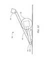
- the laser systemcomprises a laser defining a beam axis, a first mirror situated along the beam axis, a first motor, such as a stepper motor or galvanometer, defining a first axis of rotation and configured to rotate the first mirror around the first axis of rotation, and a controller.
- the controlleris configured to drive the first motor to rotate the first mirror responsive to orientation information from the orientation sensor to stabilize the laser beam.
- the controlleris also configured to aim the laser beam responsive to signals received from the human interface for aiming the laser beam.
- the laser systemis attached to ahead of the robot proximate to the video camera.
- the laser systemcan further comprise, in some of these embodiments, a second motor defining a second axis of rotation and configured to rotate a second miror around the second axis of rotation wherein the laser system is configured such that the laser beam is reflected off of the first mirror onto the second mirror.
- the second axis of rotationis perpendicular to the first axis of rotation.
- the laser systemfurther comprises a digital to analog converter in electrical communication between the controller and the stepper motor.
- the laser systemfurther comprises a hard stop positioned to provide a fixed position reference for open loop control of the first motor.
- the first mirror and/or the second mirrorcan comprise, in some embodiments, a back surface mirror.
- Yet another exemplary methodcomprises dynamically balancing a robot and projecting a stabilized laser beam from the robot while maintaining the balance.
- the methodcan comprise performing an initialization of a laser system including initializing a mirror assembly by stepping a stepper motor of the mirror assembly so that a mirror of the mirror assembly contacts a hard stop of the mirror assembly.
- Dynamically balancing the robotcan comprise, in some embodiments, measuring a change in a base angle of the robot, the base angle being defined between a first reference plane having a fixed relationship to a base of the robot and a second reference plane having a fixed relationship to an external frame of reference, and rotating wheels of the robot to correct for the change so that the wheels stay approximately centered beneath the center of gravity of the robot.
- the stabilized laser beamis projected by a laser system attached to the robot and the laser system includes optics for projecting the stabilized laser beam.
- projecting the stabilized laser beamcomprises obtaining an orientation measurement of the laser system, and adjusting the optics to compensate the aim of the laser beam, responsive to the orientation measurement, so that the laser beam remains stable in a frame of reference that is external to the robot.
- obtaining the orientation measurementcomprises measuring a change in the pitch of the robot.
- adjusting the opticsincludes microstepping two stepper motors having axes of rotation disposed perpendicular to one another.
- Projecting the stabilized laser beamcan comprise creating a symbol or gesturing with the laser beam, in some embodiments. Projecting the stabilized laser beam can also comprise, in some instances, receiving an operator input for aiming the laser beam. Projecting the stabilized laser beam can also comprise determining a distance to a surface on which the laser beam is being projected, and in some of these embodiments the method further comprises moving the robot and projecting the stabilized laser beam further comprises adjusting the aim of the laser beam to keep the laser beam fixed on the surface. In those embodiments where the robot comprises a camera, projecting the stabilized laser beam can also comprise utilizing imagery produced by the video camera to control the optics to compensate the aim of the laser beam. In various embodiments, utilizing imagery produced by the video camera comprises calculating an optic flow or tracking a feature in the robot's visual environment, for example.
- Still another exemplary methodcomprises remotely operating a robot and projecting a stabilized laser beam from the robot.
- the stabilized laser beamis projected by a laser system attached to the robot and the laser system includes optics for projecting the stabilized laser beam.
- projecting the stabilized laser beamcomprises obtaining an orientation measurement of the laser system, and adjusting the optics to compensate the aim of the laser beam, responsive to the orientation measurement, so that the laser beam remains stable in a frame of reference that is external to the robot.
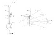
- FIGS. 1 and 2show side and front views, respectively, of a mobile self-balancing robot according to an embodiment of the present invention.
- FIG. 3shows a side view of the robot of FIGS. 1 and 2 bent at a waist joint according to an embodiment of the present invention.
- FIG. 4is a schematic representation of a first control system configured to maintain the balance of the robot of FIGS. 1-3 on the wheels, according to an embodiment of the present invention.
- FIG. 5is a schematic representation of a second control system configured to coordinate a change in the base angle of the robot of FIGS. 1-3 to accommodate a change in the waist angle of the robot of FIGS. 1-3 , according to an embodiment of the present invention.
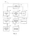
- FIG. 6is a schematic representation of a third control system configured to control the movement of the robot of FIGS. 1-3 , according to an embodiment of the present invention.
- FIG. 7shows a schematic representation of a person employing a human interface to remotely control the robot of FIGS. 1-3 , according to an embodiment of the present invention.
- FIG. 8shows the robot of FIGS. 1-3 further comprising a lean joint, according to an embodiment of the present invention.
- FIG. 9graphically illustrates a method according to an embodiment of the present invention.
- FIG. 10shows the robot of FIGS. 1-3 in a sitting posture according to an embodiment of the present invention.
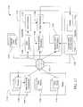
- FIG. 11shows a block diagram representation of a robotic system for providing visual telepresence to an operator according to an embodiment of the present invention.
- FIG. 12shows a schematic representation of a top view of a head of a robot to illustrate camera placement therein according to an embodiment of the present invention.
- FIG. 13shows a flattened representation of an operator view superimposed over a robot view comprising a stereo view and peripheral views according to an embodiment of the present invention.
- FIG. 14shows another flattened representation of the operator and robot views of FIG. 13 according to an embodiment of the present invention.
- FIG. 15illustrates a method for providing visual telepresence to an operator of a robot according to an exemplary embodiment of the present invention.
- FIG. 16shows a block diagram representation of a robotic system for providing visual telepresence to an operator according to an embodiment of the present invention.
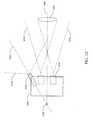
- FIG. 17shows a schematic representation of an exemplary laser system according to an embodiment of the present invention.
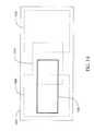
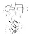
- FIGS. 18 and 19show, respectively, top and back views of an exemplary mirror assembly of the laser system of FIG. 17 , according to an embodiment of the present invention.
- FIG. 20shows a schematic representation of a perspective view of a laser system attached to a robot and proximate to a camera thereof, according to an embodiment of the present nvention.
- FIG. 21shows a schematic representation of a side view of the laser system and camera of FIG. 20 , according to an embodiment of the present invention.
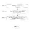
- FIG. 22illustrates certain steps of exemplary methods for providing an operator of a remotely controlled dynamically balancing robot an ability to project a stabilized laser beam from the robot, according to an embodiment of the present invention.
- the present inventionis directed to mobile self-balancing robots characterized by a generally human-like upright posture. These robots are human-like in that they are capable of bending at a waist and include control systems for maintaining balance, for maintaining a fixed location while bending at the waist, and for changing the location and the orientation of the robot. The mobility, ability to bend at the waist, and upright posture make the robots of the present invention suitable for telepresence and other applications.
- the present inventionis additionally directed to robotic systems that allow a person to remotely control a robot through a human interface. Methods of the present invention are directed to maintaining the balance of the robot at a fixed location while executing a bend at the waist, and in some embodiments additionally moving a head of the robot while bending at the waist. These methods optionally also include steps in which a person controls the bending at the waist, head movements, movements of arms, and/or controls other aspects of the robot through a human interface.
- FIGS. 1 and 2show side and front views, respectively, of a mobile self-balancing robot 100 according to an embodiment of the present invention.
- the robot 100has a generally human-like upright posture and the ability to bend at a midpoint in a manner analogous to a person bending at the waist.
- the robot 100comprises a self-propelled base 110 supported on wheels 120 and including a motor (not shown) configured to drive the wheels 120 .
- Wheels 120optionally consist of one or two wheels.
- the width of the base 110 as measured along the axis of the wheels 120is less than half of the height of the robot 100 when the robot 100 is in a fully upright configuration.
- Dynamically balancing robots, such as robot 100are sometimes referred to as inverted pendulum robots.
- the robot 100also comprises a lower segment pivotally coupled to an upper segment at a waist.
- the lower segmentcomprises a leg segment 130 extending from the base 110
- the upper segmentcomprises a torso segment 140 coupled to the leg segment 130 by a waist joint 150 .
- the robot 100further comprises an actuator 160 configured to bend the robot 100 at the waist joint 150 .
- the ability to bend at the waist joint 150allows the robot 100 to sit down and get up again, in some embodiments, as discussed below with respect to FIG. 10 .
- the torso segment 140 , the leg segment 130 , or bothinclude one or more communication components.
- a communication componentis a communication port, such as a Universal Serial Bus (USB) port, to allow a person to connect a computing system to the robot 100 .
- a communication componentis a video display screen.
- the video display screencan permit a remote operator to display information, graphics, video, and so forth to those near the robot 100 .
- the video display screenincludes a touch screen to allow input from those near the robot 100 .
- the robot 100optionally also includes a head 170 attached to the torso segment 140 .
- the head 170is disposed at the end of the torso segment 140 that is opposite the end of the torso segment 140 that is joined to the waist joint 150 , as shown in FIGS. 1 and 2 .
- the head 170is pivotally attached to the torso segment 140 , as discussed in greater detail below with respect to FIG. 7 .
- the ability of the robot 100 to bend at the waist joint 150allows the head 170 to be moved through a range of motion that in some embodiments can bring the head 170 close to the ground.
- the head 170can include instrumentation, such as sensors, cameras, microphones, speakers, a laser pointer, and/or the like, though it will be appreciated that such instrumentation is not limited to the head 170 and can also be disposed elsewhere on the robot 100 .
- the laser pointercan be disposed on an arm or finger of the robot 100 .
- the head 170can include one or more illuminators to illuminate the environment. Illuminators can be provided to produce colored illumination such as red, green, and blue, white illumination, and infrared illumination, for instance. Some embodiments also include a laser to serve as a pointer, for example, that can be controlled by a remote operator.
- the robot 100comprises a lean joint (not shown) that couples the leg segment 130 to the base 110 .
- the lean jointis described in greater detail with respect to FIG. 8 .
- the robot 100includes one or more arms (not shown) extending from the torso segment 140 and/or the leg segment 130 .
- the armscan include a human-like hand and/or a pneumatically driven gripper or other end effectors.
- control of the motion of the robot 100can be autonomous, through a human interface, or through the human interface with some autonomous capabilities.
- FIGS. 1 and 2also illustrate a coordinate axis system defined relative to the robot 100 .
- a Z-axisalso termed a vertical axis
- the center of gravity of the robot 100lies along the vertical axis, e.g. is centered above the wheels. It will be appreciated that when the robot 100 is travelling forward or backward, the center of gravity will be either forward of, or behind, the vertical axis.
- the vertical axispasses through a midpoint between the centers of wheels 120 .
- FIG. 1also shows a Y-axis perpendicular to the Z-axis.
- the Y-axisalso termed a horizontal axis, is aligned with the direction of travel of the robot 100 when both wheels 120 are driven together in the same direction and at the same rate.
- FIG. 2shows an X-axis, also termed a transverse axis, which is perpendicular to both the Z-axis and the Y-axis.
- the transverse axisruns parallel to a line defined through the centers of the wheels 120 .
- the frame of reference defined by this coordinate systemmoves with the robot 100 and is termed the internal frame of reference.
- Another frame of referencetermed the external frame of reference, is fixed relative to the environment around the robot 100 .
- FIG. 3shows a side view of the robot 100 bent at the waist joint 150 , according to an embodiment of the present invention.
- a waist angle, ⁇is defined between the leg segment 130 and the torso segment 140 at the waist joint 150 , and the actuator 160 is configured to change the waist angle.
- the waist angleis defined as an angle between a longitudinal axis 310 of the leg segment 130 and a longitudinal axis 320 of the torso segment 140 .
- Another angle, termed a base angle, ⁇that may be defined between a base reference plane 330 of the base 110 and the horizontal plane 340 .
- the base reference plane 330 and the horizontal plane 340may be parallel, but when not parallel the base reference plane 330 and the horizontal plane 340 intersect along a line that is parallel to the X-axis.
- the robot 100can bend at the waist joint 150 through a range of waist angles from about 180° to at least less than about 90° to be able to pick items off the ground and to be able to inspect beneath low objects.
- the robot 100can bend at the waist joint 150 through a range of waist angles from about 180° to about 45°, 30°, 15°, or 0°.
- the waist angleis about 180°, as in FIGS. 1 and 2 , the longitudinal axes 320 , 310 of the torso and leg segments 140 , 130 are approximately collinear.
- the base reference plane 330has a fixed relationship relative to the base 110 , however, that relationship can be defined in a variety of different ways.
- the base reference plane 330is defined through the centers of the wheels 120 and parallel to the top and bottom surfaces of the base 110 .
- the base reference plane 330is defined by either the top surface or the bottom surface of the base 110 , and in still other embodiments the base reference plane 330 is defined through the leading top edge and trailing bottom edge of the base 110 (i.e., across the diagonal of the base 110 in FIG. 3 ).
- the base reference plane 330can also be defined as being perpendicular to the longitudinal axis 310 of the leg segment 130 .
- the horizontal plane 340serves as a convenient reference, however, the base angle can also be defined between any other plane in the external frame of reference, such as a vertical plane.
- the base angleis defined between a first reference plane having a fixed relationship to the base 110 and a second reference plane having a fixed relationship to the external frame of reference.
- the base 110is supported on wheels 120 and includes one or more motors (collectively referred to herein as “the motor”) configured to drive the wheels 120 .
- the motorcan be an electric motor, for example, which in some embodiments is powered by an internal power source such as a battery system in the base 110 , while in other embodiments the motor is powered by an external power source coupled to the base 110 through a tether (not shown; see FIG. 8 ).
- the internal power sourceis disposed above the waist joint 150 , for example, in the torso segment 140 .
- Other sources of electric powersuch as a fuel cell, can also be employed, and it will be understood that the motor is not particularly limited to being electrically powered, but can also comprise an internal combustion engine, for example.
- Embodiments of the robot 100can also include two motors so that each wheel 120 can be driven independently.
- the wheels 120are adapted to the particular surfaces on which the robot 100 is intended to operate and therefore can be solid, inflatable, wide, narrow, knobbed, treaded, and so forth. In further embodiments, the wheels can be replaced with non-circular tracks such as tank treads.
- the actuator 160in some embodiments, comprises an hydraulic or pneumatic cylinder 180 connected between the torso segment 140 and either the leg segment 130 as shown, or the base 110 .
- the cylinder 180is connected to a ball joint extending frontward from the torso segment 140 and is also pivotally attached to the leg segment 130 .
- Other actuators, including electric motors,can also be employed in various embodiments.
- the electric motoris coupled to a drive train comprising gears, belts, chains, or combinations thereof in order to bend the robot 100 at the waist joint 150 .
- the center of gravity of robot 100should be as high as possible to make dynamic balancing more stable and easier to control.
- the center of gravity of the torso segment 140should also be as close to the head 170 as possible, and the center of gravity of the leg segment 130 should additionally be as close to the wheels 120 as possible so that the change in the base angle is maximized as a function of the change in the waist angle.
- the center of gravity of the combined body segments above the waiste.g., the torso segment 140 and the head 170
- the center of gravity of both segments 130 , 140should be as close to the waist joint 150 as possible so there is a minimum change in the base angle as a function of the change in the waist angle.
- the robot 100also comprises several control systems (not shown).
- a first control systemdiscussed below with reference to FIG. 4 , is configured to maintain the balance of the robot 100 on the wheels 120 .
- FIG. 5describes a second related control system configured to coordinate a change in the base angle to accommodate a change in the waist angle.
- a third related control systemallows the robot 100 to change location and/or orientation within the external frame of reference, as discussed with respect to FIG. 6 .
- FIG. 4is a schematic representation of a first control system 400 configured to maintain the balance of the robot 100 of FIGS. 1-3 on the wheels 120 , according to an exemplary embodiment.
- the first control system 400comprises the motor 410 in the base 110 for driving the wheels 120 , a balance sensor 420 , and balance maintaining logic 430 .
- the balance maintaining logic 430receives a balance signal from the balance sensor 420 and controls the motor 410 , for instance with a control signal, to apply torque to the wheels 120 , as necessary to maintain balance on the wheels 120 .
- the balance sensor 420can be disposed in the base 110 , the leg segment 130 , the torso segment 140 , or the head 170 , in various embodiments.
- the balance sensor 420can comprise, for example, a measurement system configured to measure acceleration along the three mutually perpendicular axes of the internal frame of reference noted in FIGS. 1 and 2 . Accordingly, the balance sensor 420 can comprise a set of accelerometers and/or gyroscopes, for example.
- the balance maintaining logic 430uses the acceleration measurements along the Z and Y-axes, in particular, to determine how much the robot 100 is tilting forward or backward. It will be appreciated that this tilting constitutes changing the base angle from a target base angle.
- This target base angleis the base angle at which the system is estimated to be balanced.
- the balance maintaining logic 430determines whether to rotate the wheels 120 clockwise or counterclockwise, and how much torque to apply, in order to counteract the tilting sufficiently to restore the base angle to the target base angle.
- the change in the orientation of the robot 100 as the balance maintaining logic 430 controls the motor 410 to drive the wheels 120is then detected by the balance sensor 420 to close a feedback loop.
- FIG. 5is a schematic representation of a second control system 500 configured to coordinate a change in the target base angle of the robot 100 of FIGS. 1-3 to accommodate a change in the waist angle of the robot 100 of FIGS. 1-3 , according to an embodiment of the present invention. It will be appreciated that, absent the compensation provided by the second control system 500 , a change in the waist angle will change the center of gravity of the robot 100 and tilt the base. The first control system 400 will respond to this tilt by adjusting the position of the robot 100 by either rolling the robot 100 forward or backward causing the robot 100 to move from its location.
- the target base angleis 0° (e.g., parallel to the X-Y plane). If the waist angle is then changed to 150°, moving the center of gravity forward of the wheels 120 , and the change to the waist angle is made without changing the target base angle, then the robot 100 will continuously roll forward in an attempt to keep from falling over. Without compensating for the change in waist angle, there is no static balanced state.
- the second control system 500is configured to determine the target base angle as a function of either a measured waist angle as the waist angle is changing or as a function of a target waist angle for a new posture. For example, if the measured or target waist angle is 150°, then the second control system 500 may determine, for example, that the base angle should be 25°.
- the base anglemay be determined by the second control system 500 by reference to a look-up table, by calculation according to a formula, or the like.
- the second control system 500serves to keep the robot 100 at approximately a fixed location within the external frame of reference while bending at the waist joint 150 , by coordinating the change in the base angle with the change in the waist angle so that the center of gravity is maintained approximately over the axis defined between the wheels 120 .
- the base anglemay vary while the robot 100 is approximately still.
- the base angleis a value that is determined by the second control system 500 based on the waist angle, rather than being used as a control mechanism by a user, as in the prior art.
- the second control system 500comprises a base angle determining logic 510 which receives a signal generated by a waist angle input device 520 , determines a target base angle, and sends the target base angle to the balance maintaining logic 430 which, in turn, activates the motor 410 .
- the waist angle input device 520comprises a waist angle sensor disposed on the robot 100 at the waist joint 150 .
- the base angle determining logic 510responds to changes in the waist angle, continuously updating the base angle in response to the waist angle.
- the waist angle sensorcan be, for example, an optical encoder mounted on the axis of the waist joint 150 , or a linear potentiometer integrated with the actuator 160 . Some embodiments include more than one waist angle sensor configured to operate redundantly.
- the waist angle input device 520comprises an external input device configured to provide a target waist angle to base angle determining logic.
- waist angle input device 520may include a joystick, mouse, position sensor, processor, or some other device configured for a user to remotely actuate the actuator 160 .
- an external operatorcan send a signal to the robot 100 to set the waist angle to a particular angle, or to bend at the waist joint 150 by a certain number of degrees.
- the base angle determining logic 510determines the target base angle for the target waist angle and then provides the target base angle to the balance maintaining logic 430 .
- the balance maintaining logic 430also receives the signal from the waist angle input device 520 and synchronizes the control of the motor 410 together with the control of the actuator 160 .
- the waist angle input device 520may comprise logic within the robot 100 itself, in those embodiments where the robot 100 is configured to act autonomously or semi-autonomously.
- FIG. 7further describes how the waist angle input device 520 can be part of a human interface for controlling the robot 100 .
- the base angle determining logic 510determines the target base angle for a given waist angle by accessing a set of previously determined empirical correlations between the base and waist angles. These empirically determined correlations can be stored in a look-up table or can be represented by a formula, for example. In some embodiments, determining the target base angle for a target waist angle optionally comprises searching the look-up table for the base angle that corresponds to the target waist angle, or interpolating a base angle where the target waist angle falls between two waist angles in the look-up table. In other embodiments, the base angle determining logic 510 comprises base angle calculator configured to calculate the base angle by applying a formula, performing a finite element analysis, or the like.
- a third control systemdiscussed below with respect to FIG. 6 , is configured to control the movement of the robot 100 in order to return the robot 100 back to the original location.
- positions of arms, weight carried, or other factors influencing center of gravitymay be taken into account by base angle determining logic 510 when determining the target base angle.
- the base angle determining logic 510determines the target base angle for a given waist angle by performing a calculation.
- the overall center of gravity of the robot 100can be computed so long as the masses and the centers of gravity of the individual components are known (i.e., for the base 110 , segments 130 and 140 , and head 170 ) and the spatial relationships of those components are known (i.e., the base and waist angles).
- the center of gravity of the robot 100will be aligned with the vertical axis. Therefore, in response to a change in the waist angle, or in response to an input to change the waist angle, the base angle determining logic 510 can solve for the base angle that will keep the center of gravity of the robot 100 aligned with the vertical axis.
- FIG. 6is a schematic representation of a third control system 600 configured to control the movement of the robot 100 of FIGS. 1-3 , according to an embodiment of the present invention.
- Movement of the robot 100can comprise rotating the robot 100 around the vertical axis, moving or returning the robot 100 to a particular location, moving the robot 100 in a direction at a particular speed, and executing turns while moving.
- the third control system 600comprises position tracking logic 610 configured to track the location and orientation of the robot 100 relative to either the internal or external frame of reference.
- the position tracking logic 610tracks other information by monitoring the rotation of the wheels 120 and/or by monitoring other sources like the balance sensor 420 . Examples of other information that can be tracked include the velocity and acceleration of the robot 100 , the rate of rotation of the robot 100 around the vertical axis, and so forth.
- the position tracking logic 610can track the location and the orientation of the robot 100 , for example, by monitoring the rotations of the wheels 120 and by knowing the circumferences thereof. Location and orientation can also be tracked through the use of range finding equipment such as sonar, radar, and laser-based systems, for instance. Such equipment can be either be part of the robot 100 or external thereto. In the latter case, location and orientation information can be received by the position tracking logic 610 through a wireless communication link.
- Devices or logic for monitoring wheel rotation, as well as the range finding equipment noted above,comprise examples of position sensors.
- the third control system 600also comprises movement logic 620 configured to receive at least the location information from the position tracking logic 610 .
- the movement logic 620can compare the received location information against a target location which can be any point within the relevant frame of reference. If the location information received from the position tracking logic 610 is different than the target location, the movement logic 620 directs the balance maintaining logic 430 to move the robot 100 to the target location. Where the target location is fixed while the second control system 500 coordinates a bend at the waist joint 150 with a change in the base angle, the third control system 600 will return the robot 100 to the target location to correct for any inaccuracies in the target base angle.
- the balance maintaining logic 430has the additional capability to change the base angle so that the robot 100 deviates from balance momentarily to initiate a lean in the intended direction of travel. Then, having established the lean in the direction of travel, the balance maintaining logic 430 controls the motor 410 to apply torque to rotate the wheels 120 in the direction necessary to move in the desired direction. For example, with reference to FIG. 3 , to move the robot 100 to the right in the drawing, the balance maintaining logic 430 initially directs the motor 410 to turn the wheels 120 counterclockwise to cause the robot 100 to pitch clockwise. With the center of gravity of the robot 100 to the right of the vertical axis, the balance maintaining logic 430 next turns the wheels 120 clockwise so that the robot 100 rolls to the right.
- the movement logic 620can also compare orientation information received from the position tracking logic 610 against a target orientation. If there is a difference between the two, the movement logic 620 can instruct the balance maintaining logic 430 to rotate the robot 100 to the target orientation.
- the balance maintaining logic 430can control the wheels 120 to counter-rotate by equal amounts to rotate the robot 100 around the vertical axis by the amount necessary to bring the robot 100 to the target orientation.
- Other information tracked by the position bucking logic 610can be similarly used by the movement logic 620 and/or components of other control systems.
- Target locations and orientationscan be determined by the movement logic 620 in a variety of ways.
- the movement logic 620can be programmed to execute moves at particular times or in response to particular signals.
- the robot 100is configured to act autonomously, and in these embodiments the robot 100 comprises autonomous logic configured to update the movement logic 620 as needed with new location and orientation targets.
- the movement logic 620can also be configured, in some embodiments, to receive location and orientation targets from a human interface, such as described below with respect to FIG. 7 .
- the robot 100also comprises a control input logic 640 configured to receive movement control signals from a movement control input device 630 .
- Control input logic 640may be further configured to calculate a target location or velocity based on these signals, and to communicate the target location or velocity to the movement logic 620 .
- Movement control input device 630may comprise a joystick, mouse, position sensor, processor, or some other device configured for a user to indicate a target location or movement.
- FIG. 7shows a schematic representation of a person 700 employing a human interface to remotely control the robot 100 of FIGS. 1-3 , according to an embodiment of the present invention.
- the human interfacecomprises a controller 710 that can be disposed, in some embodiments, within a backpack or a harness or some other means configured to be positioned on the body of the person 700 .
- the controller 710can also be carried by the person or situated remotely from the person 700 .
- the controller 710is optionally an example of waist angle input device 520 and or movement control input device 630 .
- the controller 710provides control signals to the base angle determining logic 510 and/or the control input logic 640 . These control signals may be configured to provide a new target position and/or a new target waist angle.
- the controller 710can be connected to the robot 100 through a network 715 , in some embodiments.
- the network 715can be an Ethernet, a local area network, a wide area network, the Internet, or the like.
- the connections to the network 715 from both or either of the controller 710 and robot 100can be wired or wireless connections.
- the controller 710 and the robot 100are in direct communication, either wired or wirelessly, without the network 715 .
- the robot 100transmits signals and/or data back along the communication path to the controller 710 or other logic configured to operate the human interface to provide, for example, video, audio, and/or tactile feedback to the person 700 .
- the controller 710comprises one or more sensors and/or detectors such as a position sensor 720 configured to detect an angle, ⁇ , of a torso 730 of the person 700 .
- the angle of the torso 730is an angle made between a longitudinal axis 740 of the torso 730 and a vertical axis 750 . More specifically, when the person 700 is standing erect, the angle of the torso 730 is about zero and increases as the person 700 bends at the waist, as illustrated.
- the position sensor 720can make this measurement, for example, through the use of accelerometers and/or gyroscopes positioned on the back of the person 700 .
- the longitudinal axis 740here is defined by the orientation of the position sensor 720 with respect to the external frame of reference. More generally, just as the base angle is defined by two reference planes, one fixed to the base 110 and one fixed to the external frame of reference, the longitudinal axis 740 is fixed to the torso 730 and the vertical axis 750 is fixed to the external frame of reference. And just as in the case of the base angle, these axes 740 , 750 can be arbitrarily fixed. The longitudinal axis 740 and the vertical axis 750 are merely used herein as they are convenient for the purposes of illustration.
- the controller 710can also comprise other sensors and/or detectors to measure other aspects of the person 700 , such as the orientation of the person's head 760 , where the person is looking, location and motion of the person's arms, the person's location and orientation within a frame of reference, and so forth.
- other sensors and detectorshave been omitted from FIG. 7 , but it will be appreciated that the controller 710 can support many such other sensors and detectors in a manner analogous to that described herein with respect to the position sensor 720 .
- the controller 710 and the position sensor 720 , and/or other sensors and detectorsare integrated into a single device.
- the controller 710may communicate with the position sensor 720 , for instance, over a wireless network.
- the controller 710optionally provides movement control signals from which the control input logic 640 can calculate a target location, for example.
- the movement control signalscan be derived from measurements acquired from sensors and detectors configured to measure various aspects of the person 700 .
- Other movement control signals provided by the controller 710may also be derived from a movement control input device 630 such as a joystick 755 .
- any of the sensors, detectors, and control input devices 630can bypass the controller 710 and communicate directly to the control input logic 640 or the base angle determining logic 510 .
- the controller 710can determine the angle of the torso 730 from the position sensor 720 and provide a control input signal derived from the angle of the torso 730 to the control input logic 640 .
- the control input signalcomprises a target waist angle for the robot 100 , determined by the controller 710 , while in other embodiments the control input signal simply comprises the angle of the torso 730 , and in these embodiments the control input logic 640 determines the target waist angle.
- the control input logic 640provides the target waist angle to the base angle determining logic 510 to determine the target base angle, and provides the target waist angle to the movement logic 620 , or to the balance maintaining logic 430 , to control the actuator 160 .
- either the controller 710 or the control input logic 640can determine the target waist angle from the angle of the torso 730 , in various embodiments. In some embodiments, this determination is performed by setting the target waist angle equal to the angle of the torso 730 . In this way the waist angle of the robot 100 emulates the angle of the person's torso 730 . Other embodiments are intended to accentuate or attenuate the movements of the person 700 when translated into movements of the robot 100 , as discussed below.
- the angle of the torso 730 of the person 700is less than the waist angle of the robot 100 to illustrate embodiments in which the person 700 bends at the waist and the degree of bending is accentuated so that the robot 700 bends further, or through a greater angle, than the person 700 .
- the target waist angleis determined by the controller 710 , or the control input logic 640 , to be greater than the angle of the torso 730 .
- the target waist anglecan be derived, for example, from a mathematical function of the angle of the torso 730 , such as a scaling factor.
- a look-up tableincludes particular waist angles of the robot 100 for successive increments of the angle of the torso 730 .
- deriving the target waist angle of the robot 100 from the angle of the torso 730comprises finding in the look-up table the waist angle of the robot 100 for the particular angle of the torso 730 , or interpolating a waist angle between two waist angles in the look-up table.
- the head 760 of the person 700can be used to control the head 170 of the robot 100 .
- the controller 710can comprise one or more sensors (not shown) configured to monitor the orientation of the head 760 of the person 700 , including tilting up or down, tilting to the left or right, and rotation around the neck (essentially, rotations around three perpendicular axes).
- the direction in which the eyes of the person 700 are lookingcan also be monitored.
- the controller 710can use such sensor data, in some embodiments, to derive a target orientation of the head 170 to transmit as a control input signal to the control input logic 640 .
- the controller 710transmits the data from the sensors as the control input signal to the control input logic 640 , and then the control input logic 640 derives the target orientation of the head 170 .
- the controller 710 or control input logic 640is configured to keep the orientation of the head 170 of the robot 100 equal to that of the head 760 of the person 700 , each with respect to the local external frame of reference. In other words, if the person 700 tilts her head forward or back by an angle, the head 170 of the robot 100 tilts forward or back by the same angle around a neck joint 770 . Likewise, tilting to the left or right and rotation around the neck (sometimes referred to as panning) can be the same for both the head 760 of the person 700 and the head 170 of the robot 100 , in various embodiments. In some embodiments, the neck joint 770 is limited to panning and tilting forward and back, but not tilting to the left and right.
- keeping the orientation of the head 170 of the robot 100 equal to that of the head 760 of the person 700can comprise tilting the head 170 of the robot 100 through a greater or lesser angle than the head 760 of the person.
- the head 760 of the robot 100nevertheless can remain oriented such that stereo cameras (not shown) in the head 170 have a level line of sight to match that of the person 700 .
- the head 170 of the robot 100tilts back through a greater angle than the head 760 of the person 700 to compensate for the greater bending at the waist joint 150 .
- FIG. 8shows the robot 100 of FIGS. 1-3 further comprising a lean joint 800 , according to an embodiment of the present invention.
- the lean joint 800can be disposed along the leg segment 130 near the base 110 , while in other embodiments the lean joint couples the leg segment 130 to the base 110 as illustrated by FIG. 8 .
- the lean joint 800permits rotation of the leg segment 130 around the horizontal axis relative to the base 110 .
- the lean joint 800permits tilting of the leg segment 130 in a direction that is perpendicular to the movement of the torso segment 140 enabled by the waist joint 150 . This can permit the robot 100 to traverse uneven or non-level surfaces, react to forces that are parallel to the transverse axis, lean into turns, and so forth.
- control logic described with respect to FIGS. 4-6can keep the leg segment generally aligned with the Y-Z plane while the base 110 tilts relative to this plane due to a sloped or uneven surface.
- control logiccan control the leg segment 130 to lean into turns.
- the robot 100includes one or more stabilizers 810 , such as springs or gas-filled shock-absorbers for example, configured to restore the leg segment 130 to an orientation perpendicular to the base 110 .
- the robot 100additionally comprises, or alternatively comprises, one or more actuators 820 configured to move the leg segment 130 around the lean joint 800 relative to the base 110 .
- the balance maintaining logic 430receives information from the balance sensor 420 regarding tilting around the transverse axis and controls the actuator 820 to counteract the tilt.
- the one or more actuators 820comprise hydraulic or pneumatic cylinders. It will be understood that one or more stabilizers can also be analogously employed at the waist joint 150 in conjunction with the actuator 160 .
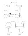
- FIG. 8also illustrates an optional tether 830 extending from the base 110 .
- the tethercan be used to provide communications, power, and/or compressed air for pneumatics to the robot 100 .
- Those embodiments that include the tether 830may optionally also include an actuated tail 840 extending outward from the base and coupling the tether 830 to the base 110 .
- the tail 840when actuated, rotates around a pivot point in order to move the tether 830 out of the way of the wheels 120 when the robot 100 is driven backwards.
- FIG. 9graphically illustrates a method according to an embodiment of the present invention.
- the robot 100maintains balance on two wheels and maintains a location within the external frame of reference while bending at the waist joint 150 .
- FIG. 9shows the robot 100 configured according to a first posture at a time 1 and configured according to a second posture at a later time 2 .
- the robot 100is configured with a first waist angle, ⁇ 1 , and a first base angle, ⁇ 1
- the robot 100is configured with a second waist angle, ⁇ 2 , and a second base angle, ⁇ 2 .
- the robot 100 at time 1is at a location in the external frame of reference given the coordinates (0, 0) remains at the location until time 2 .
- Balance of the robot 100 on two wheelscan be maintained by a feedback loop. For example, when a change in a base angle of the robot 100 is measured, the wheels 120 are rotated to correct for the change so that the base angle is maintained and the wheels 120 stay approximately centered beneath the center of gravity of the robot 100 .
- Bendingis accomplished over the interval from time 1 to time 2 by changing the base angle while changing the waist angle such that the wheels do not appreciably rotate.
- changing the base anglecomprises rotating the base around an axis of the wheels 120
- changing the waist anglecomprises rotating the torso segment around the waist joint 150 relative to the leg segment 130 .
- changing the base angle while changing the waist angle such that the wheels do not appreciably rotateincludes embodiments where the waist angle and the base angle change continuously over the same period of time and embodiments where changing the angles is performed in alternating increments between incremental changes in the waist angle and incremental changes in the base angle.
- the robot 100is capable of transitioning between postures without the wheels 120 appreciably rotating, in other words, without the robot 100 rolling forward and back. “Appreciably” here means that slight deviations back and forth can be tolerated to the extent that the robot 100 provides the necessary level of stability for an intended purpose, such as a robot 100 operated by telepresence.
- changing the base angle while changing the waist anglecan be accomplished by balancing the torque applied by the motor 410 against the torque applied to the wheels 120 by the shift in the center of gravity due to the changing waist angle.
- the second control system 500can be employed to change the base angle while changing the waist angle, but it will be understood that the control system 500 is merely one example of a computer-implemented control suitable for performing this function.
- Methods illustrated generally by FIG. 9can further comprise receiving a target waist angle.
- the base angle determining logic 510can receive the target waist angle from autonomous logic of the robot 100 , or from a human interface such as controller 710 .
- changing the base angleincludes determining a target base angle from the target waist angle such as with the base angle determining logic 510 .
- determining the target base angle from the target waist angleincludes searching a database for the base angle that corresponds to the target waist angle. In other instances the target base angle is calculated based on the target waist angle.
- Methods illustrated generally by FIG. 9can further comprise either changing an orientation of the head 170 of the robot 100 , or maintaining a fixed orientation of the head 170 , while changing the waist angle.
- changing the orientation of the head 170can be accomplished in some embodiments by monitoring the orientation of the head 760 of the person 700 , and in further embodiments, the direction in which the eyes of the person 700 are looking.
- the orientation of the head 170can follow the orientation of the head 760 of the person 700 , for example.
- the methodcan comprise deriving an orientation of the head 170 from the sensor data with the controller 710 and then transmitting the target orientation as a control input signal to the control input logic 640 .
- Other embodimentscomprise transmitting the sensor data as the control input signal to the control input logic 640 , and then deriving the target orientation of the head 170 with the control input logic 640 .
- the target orientationcan be achieved through rotating the head 170 around a neck joint 770 relative to the torso segment 140 .
- the rotationis around an axis, disposed through the neck joint 770 , that is parallel to the transverse axis. Additional rotations around the other two perpendicular axes can also be performed in further embodiments.
- Some embodimentsfurther comprise maintaining a fixed orientation of the head 170 while changing the waist angle.
- the target orientationis by a feedback loop based on a visual field as observed by one or more video cameras disposed in the head 170 . If the visual field drifts up or down, the head 170 can be rotated around an axis of the neck joint 770 in order to hold the visual field steady.
- FIG. 10shows the robot 100 in a sitting posture according to an embodiment of the present invention.
- the sitting posturecan be used, for example, as a resting state when the robot 100 is not in use.
- the sitting postureis also more compact for transportation and storage.
- the leg segment 130includes a bumper 1000 for making contact with the ground when the robot 100 is sitting. It can be seen that the sitting posture of FIG. 10 can be achieved by continuing the progression illustrated by FIG. 9 .
- the robot 100will not be able to bend at the waist joint 150 all of the way to the sitting posture, but can come close, for example, by bringing the bumper 1000 to about 6 inches off of the ground. From this position, the robot 100 can safely drop the remaining distance to the ground.
- the center of gravity of the torso segment 140should also be as close to the head 170 as possible, and the center of gravity of the leg segment 130 should additionally be as close to the wheels 120 as possible.
- the length of the torso segment 140can be longer than the length of the leg segment 130 .
- the length of the torso segment 140is shown to be longer in FIG. 10 than in preceding drawings to illustrate this point.
- the center of gravity of the combined body segments above the waist joint 150such as the torso segment 140 and head 170 , is further than half their overall length from the waist joint 150 .
- FIG. 11shows a block diagram representation of a robotic system 1100 for providing visual telepresence to an operator 1105 according to an embodiment of the present invention.
- the system 1100comprises a robot 1110 , a controller 1115 , such as a processor, an optional head-tracking sensor 1120 configured to track the orientation of the head the operator 1105 , and a display 1125 configured to provide an image of the robot's visual environment to the operator 1105 .
- the robot 1110can be in direct communication with the controller 1115 , or can be in communication across a network 715 ( FIG. 7 ) as shown in FIG. 11 .
- the network 715can comprise an Ethernet, a local area network, a wide area network, the Internet, or the like.
- the head-tracking sensor 1120 and the display 1125can each be in direct communication with the controller 1115 , as shown, or in communication through a network.
- the controller 1115is integral with other controllers that comprise the human interface, such as controller 710 ( FIG. 7 ).
- the head-tracking sensor 1120can comprise a magnetic compass or a set of rate gyros, for example.
- the display 1125can be a video monitor, such as that of a work station, or an image projection system of a head-mounted display, for example.
- the head-tracking sensor 1120 and the display 1125can be integrated into the same head-mounted display.
- more than one display 1125can be employed, for example, one display 1125 can be part of a head-mounted display worn by the operator 1105 and another display 1125 can be provided as a video screen for observers.
- the robot 1110is not limited to self-balancing robots such as robot 100 (e.g., FIGS. 1-3 ), but can include any robot, whether mobile or fixed at a location, that includes a plurality of video cameras 1130 .
- the robot 1110is characterized by a generally human-like upright posture
- at least two of the video cameras 1130are disposed on a head of the robot 1110 (e.g. head 170 ) and arranged so as to provide a stereoscopic view. The placement of video cameras 1130 is discussed in greater detail with respect to FIG. 12 .
- Embodiments of the robot 1110can include pose sensors 1135 which are devices that are configured to provide data from which the spatial location and aim of the video cameras 1130 relative to a frame of reference can be calculated. Accordingly, pose sensors can 1135 can provide data concerning the angles of the joints of the robot 1110 , such as that of the waist joint 150 ( FIG. 1 ) or the lean joint 800 ( FIG. 8 ). Other pose sensors 1135 can be configured to measure other characteristics of the robot 1110 , such as rotational attributes like the amount of, or the rate of change of, pitch, roll and yaw. Pose sensors 1135 can comprise, in various embodiments, an inertial measurement unit (IMU), optical encoders and/or linear potentiometers.
- IMUinertial measurement unit
- the robot 1110can optionally include logic 1140 for performing video encoding and compression of the signals produced by the video cameras 1130 .
- the robot 1110can optionally also include one or more data sources 1145 .
- data sources 1145include such devices as microphones, a global positioning receiver, and environmental sensors such as for temperature, atmospheric sampling, radiation monitoring, etc.
- the head-tracking sensor 1120provides signals regarding the orientation of the head of the operator 1105 , and these signals are used to aim the video cameras 1130 , for example, by changing the posture of the robot 1110 by rotating the head of the robot 1110 and/or by bending the robot 1110 at one or more joints.
- the video cameras 1130are movably mounted to the robot 1110 so that the video cameras 1130 can be aimed without moving the robot 1110 .
- Control over the aiming of the video cameras 1130can be performed by a controller such as controller 710 ( FIG. 7 ) or the logic described above with respect to the control systems 400 - 600 of the robot 100 . For clarity, this controller has been omitted from FIG. 11 .
- FIG. 12shows a schematic representation of a top view of a head 1200 of the robot 1110 to illustrate the placement of video cameras 1130 according to an embodiment of the present invention.
- the video cameras 1130in the embodiment illustrated by FIG. 12 , comprise a pair of stereo cameras 1210 configured to aim approximately in the same direction.
- the fields of view 1215 of the stereo cameras 1210overlap to form a common field of view 1220 that in some embodiments can be presented to the operator 1105 as a stereo image of the visual environment of the robot 1110 .
- the stereo cameras 1210can comprise high resolution cameras, for example, high-definition (HD) cameras.
- HDhigh-definition
- the video cameras 1130also comprise at least one peripheral camera 1230 configured to aim in a direction different than that of the pair of stereo cameras 1210 , but with a field of view 1235 that at least partially overlaps the field of view 1215 of at least one of the stereo cameras 1210 .
- FIG. 12only shows one such peripheral camera 1230 , however, it will be appreciated that some embodiments include sufficient peripheral cameras 1230 such that their overlapping fields of view 1215 , 1235 of the set of video cameras 1130 encompass an entire 360° field of view.
- One or more of the peripheral cameras 1230can include, for example, an omni-lens, a fish eye lens, or a telephoto lens.
- stereo cameraas used herein is not meant to imply that a single stereo camera 1210 is capable of producing a stereo image, but rather that the pair of stereo cameras 1210 can be employed together to produce stereo images. While the cameras 1210 and 1230 are differentiated herein as being either “stereo” or “peripheral,” it should be understood that the same type of video camera can be employed for both, in some embodiments. In other embodiments, stereo cameras 1210 and peripheral cameras 1230 can be different types of cameras. For instance, the fields of view 1235 of the peripheral cameras 1230 , in some embodiments, are wider than the fields of view 1215 of the stereo cameras 1210 . Likewise, in some embodiments the peripheral cameras 1230 are characterized by lower resolutions than the stereo cameras 1210 .
- a field of view 1235 of a peripheral camera 1230at least partially overlaps the field of view 1215 of at least one of the stereo cameras 1210 . It should be noted, however, that not every peripheral camera 1230 is required to have a field of view 1235 that overlaps with a field of view 1215 of a stereo camera 1210 , so long as at least one peripheral camera 1230 has a field of view 1235 that overlaps in this manner.
- peripheral cameras 1230can be aimed in the direction opposite to the direction that of the pair of stereo cameras 1210 is aimed, as well as at arbitrary angles to the direction that of the pair of stereo cameras 1210 is aimed, such as 30°, 45°, 60°, 90, 120°, 135°, and 150°.
- the video cameras 1210 and 1230can be mounted internally to the head 1200 as shown in FIG. 12 , external to the head 1200 , or some can be mounted internally while some are mounted externally. It should be understood that the video cameras 1130 need not be mounted on the head 1200 of the robot 1110 , and in some embodiments the video cameras 1130 are attached to the robot 1110 in other ways, such as by being supported on a boom extending from the robot 1110 . It will also be appreciated that the video cameras 1130 do not need to all be fixed to the same part of the robot 1110 . For instance, some video cameras 1130 can be attached to the head 1200 of the robot 1110 , while another video camera 1130 can be attached to the torso segment 140 .
- the video cameras 1130are optionally arranged around a common reference point 1240 .
- a centerline 1245 of the common field of view 1220should intersect the centerlines 1250 of the fields of view 1235 of the peripheral cameras 1230 .
- This reference point 1140where the centerlines 1245 , 1250 of the fields of view 1220 , 1235 converge, is the point from which the controller 1115 renders the visual environment. It will be appreciated that although the reference point 1240 in FIG. 12 is represented as being exterior to the head 1200 , the reference point 1240 can also be interior to the head 1220 .
- the cameras 1130are not required be arranged such that all centerlines 1245 , 1250 are coplanar, as illustrated in FIG. 12 , rather, some cameras 1130 can have centerlines 1245 , 1250 that are not coplanar with the other cameras 1130 . More generally, in some embodiments the cameras 1130 are arranged such that the cameras 1130 are approximately confocal.
- the controller 1115comprises logic that renders an image to the display 1125 .
- the logic of the controller 1115optionally includes video decompression logic 1150 configured to decompress the compressed video signals received from the video encoding and compression logic 1140 of the robot 1110 . In those embodiments in which the video signals from the video cameras 1130 are not compressed, the decompression logic 1150 is not required.
- the logic of the controller 1115also can include lens correction logic 1155 .
- the lens correction logic 1155is configured to receive the decompressed video signals from the decompression logic 1150 and remove image distortions such as those distortions due to lens curvature to produce corrected video signals from each of the video cameras 1130 .
- the corrected video signalsare then provided to image rendering logic 1160 of the controller 1115 , discussed below.
- video decompression logic 1150provides decompressed uncorrected video signals to the image rendering logic 1160 .
- uncompressed and uncorrected video signalsare received by the image rendering logic 1160 from the video cameras 1130 .
- Lens distortionis discussed in detail in “A Flexible New Technique for Camera Calibration” by Zhengyou Zhang, Technical Report MSR-TR-98-71, Microsoft Corporation, Redmond, Wash., December 1998, incorporated herein by reference. Methods for lens correction are described in detail in U.S. Pat. No. 6,002,525, issued to Richard J. Poulo et al., which is also incorporated herein by reference.
- the logic of the controller 1115also can include heads up display generation logic 1165 , in some embodiments.
- data from data sources 1145 and/or from one or more external data sources 1170 that are external to the robot 1110is received and transformed into a heads up display.
- external data sources 1170include cameras that are disposed external to the robot 1110 .
- the heads up displaycan include, in various embodiments, maps, widgets such as on-screen menus, alternate camera views, and information from sensors and instruments such as from a speedometer, an odometer, and temperature sensors, for example.
- the heads up displayin some embodiments, provides a dashboard-style representation to represent such information.
- the heads up display produced by the heads up display generation logic 1165is also provided to the image rendering logic 1160 .
- the logic of the controller 1115also includes operator view in robot space generation logic 1175 .
- Logic 1175is configured to receive signals from the pose sensors 1135 and, in some embodiments, also from the head-tracking sensor 1120 to generate an operator view.
- the logic 1175passes the operator view to the image rendering logic 1160 which employs the operator view to determine a portion of the video signals from the video cameras 1130 that will be rendered as an image to the display 1125 .
- the logic 1175defines a robot space and an operator space.
- the robot spaceis defined as having a frame of reference fixed to the robot 1110 , such as to a location in the head 1200 of the robot 1110 .
- the logic 1175is configured with information for each video camera 1130 such as the spatial coordinates that define the camera's position and aim in real space relative to the frame of reference fixed to the robot 1110 .
- Such informationcan also comprise the properties of the camera's lens (e.g., wide or narrow angle) that together with the spatial coordinates defines a field of view of the video camera 1130 in real space, such as the fields of view 1215 and 1235 , and similarly defines the corresponding view for the video camera 1130 relative to the same frame of reference within the robot space.
- a field of view 1215 , 1235 of a video camera 1130is a representation of that portion of the robot's visual environment that is received by the video camera 1130 .
- a view in a virtual spacesuch as the robot space, is a representation of a hypothetical projection of the video signal from a point in the virtual space onto a screen at some distance from that point. Since the logic 1175 is configured with the information noted above, the logic 1175 is able to construct views in the robot space that have the same spatial relationships as the fields of view 1215 , 1235 of the video cameras 1130 . Accordingly, where fields of view such as 1215 and 1235 overlap in real space, the corresponding views of the video cameras 1130 in the robot space also overlap.
- FIG. 13shows a flattened representation of a robot view 1300 comprising a stereo view 1310 corresponding to the stereo field of view 1220 of the video cameras 1210 and peripheral views 1320 corresponding to the fields of view 1235 of peripheral cameras 1230 according to an embodiment of the present invention.
- the stereo view 1310corresponds to the field of view 1220 of the video cameras 1210 as if projected onto a screen at some distance in robot space.
- each peripheral view 1320corresponds to the field of view 1235 of a peripheral video camera 1230 .
- the robot view 1300can also comprise other views omitted from FIG. 13 for clarity, such as the views corresponding to the individual fields of view 1215 of the individual video cameras 1210 .
- the logic 1175defines an operator space including an operator frame of reference to represent the perspective of the operator 1105 .
- An operator viewis fixed relative to the operator frame of reference.
- the operator viewrepresents the portion of the robot view 1300 that the image rendering logic 1160 will ultimately provide to the display 1125 .
- the operator frame of referenceis defined relative to the robot frame of reference, for example, in the case of the robot 100 , at a height above the center of the base 110 .
- the orientation of the operator frame of reference relative to the robot frame of referencecan vary according to the signals from the head-tracking sensor 1120 such that the orientation of the operator frame of reference follows the orientation of the head of the operator 1105 . Because the relationship between the two frames of reference is known, the logic 1175 can define a first transformation between the robot frame of reference and the operator frame of reference.
- an operator view 1330can be seen in an initial position with respect to the robot view 1300 .
- the logic 1175changes the orientation of the operator frame of reference relative to the robot frame of reference according to the signals from the head-tracking sensor 1120 . Since the operator view 1330 is fixed in the operator frame of reference, the first transformation is applied to the operator view 1330 to reposition the operator view 1330 to a new position with respect to the robot view 1300 . Thus, for example, if the operator 1105 turns his head to the left, the operator view 1330 will correspondingly move left in FIG. 13 , to a new position as illustrated by FIG. 14 .
- Rotation of the operator view 1330 relative to the robot view 1300is also possible, for instance, where the operator's head rolls clockwise or counterclockwise.
- the signals from the head-tracking sensor 1120are also used to aim the video cameras 1130 , as the aim of video cameras 1130 follow the orientation of the operator's head, the operator view 1330 will return to the initial position in FIG. 13 .
- the logic 1175additionally or alternatively receives signals from the pose sensors 1135 which are used to reposition the operator view 1330 relative to the robot view 1300 to correct for certain motions of the robot 1110 in order to steady the image rendered to the display 1125 by the image rendering logic 1160 .
- the robot 1110is rocking back and forth while balancing, in other words, if the robot 1110 is pitching around the X-axis ( FIG. 2 ), then the portions of the robot's visual environment visible within the fields of view 1215 , 1235 of the several video cameras 1130 will vary with the rocking. For this simple pitching motion, the robot's visual environment moves up and down through the fields of view 1215 of the cameras 1210 along a vertical line.
- peripheral camera 1230aimed parallel to the X-axis
- the robot's visual environment within the field of view 1235will rotate clockwise and counterclockwise around the centerline 1250 and can also move back and forth along a horizontal line.
- Peripheral cameras 1230 aimed in other directionscan observe combinations of these effects.
- the logic 1175When the logic 1175 receives signals from the pose sensors 1135 that indicate a change in the posture of the robot 1110 due to bending or balancing, for example, the logic 1175 calculates from those signals the changes in the positions and aiming of the video cameras 1130 relative to the external frame of reference.
- the logic 1175is further configured to define a second transformation between the robot frame of reference and the operator frame of reference that mirrors the changes in the positions and aiming of the video cameras 1130 relative to the external frame of reference.
- the second transformationwhen applied to the operator view 1330 , varies the position of the operator view 1330 relative to the robot view 1300 in an inverse relationship to the changes in the positions and aiming of the video cameras 1130 .
- the logic 1175shifts the operator view 1330 relative to the robot view 1300 such that in FIG. 13 the operator view 1330 would shift upward from the initial position. Accordingly, an image of the robot's visual environment rendered within the operator view 1330 and displayed on the display 1125 can remain approximately stationary while the robot 1110 balances and performs other tasks.
- the logic 1175determines the second transformation only as a function of the pitch of the video cameras 1130 , while in other embodiments the second transformation can also be a function of either or both of yaw and roll. In further embodiments, the second transformation can also be a function of a spatial translation of the video cameras 1130 .
- the logic 1175is configured to provide two transformations that dictate what portion of the robot's visual environment is presented to the display 1125 by the image rendering logic 1160 .
- One transformationcorrects for certain motions of the robot 1110 , such as rocking due to balancing.
- the portion of the visual environment presented to the display 1125varies in parallel with the motions of the robot 1110 so that the image rendered to the display 1125 is steady despite those motions.
- the second transformationcorrects for any difference between where the operator 1105 is looking and where the video cameras 1130 are presently aimed, for instance, when the video cameras 1130 are being repositioned in response to signals from the head-tracking sensor 1120 .
- the image rendering logic 1160receives video signals from the video cameras 1130 , as optionally corrected by lens correction logic 1155 , and also receives the transformations determined by the logic 1175 .
- the image rendering logic 1160is configured to stitch together the video signals from video cameras 1130 where the fields of view 1115 , 1235 overlap in order to generate a composite video signal that is mapped to the robot view 1330 . Exemplary techniques for stitching together the video signals include cross fading and view morphing.
- the image rendering logic 1160is also configured to apply the transformations received from the logic 1175 to reposition the operator view 1330 relative to the robot view 1300 .
- the image rendering logic 1160is further configured to render an image to the display 1125 from the portion of the composite video signal that maps to the operator view 1330 .
- the image rendering logic 1160renders the image to the display 1125 as if projected onto a screen at a distance from a point in the operator space.
- the pointis defined to be between the eyes of the operator 1105 .
- the image rendering logic 1160is configured to give each eye a set of coordinates and images are presented selectively with only the video from the left video camera 1210 being presented to the operator's left eye and only the video from the right video camera 1210 being presented to the operator's right eye.
- the image rendering logic 1160can be configured to receive the heads up display from the heads up display generation logic 1165 and add the heads up display to the image rendered to the display 1125 .
- the heads up displayis rendered as if located at an infinite distance from the operator 1105 .
- the image rendering logic 1160is configured to provide augmented reality by adding virtual features to the visual environment of the image rendered by the logic 1160 .
- a visual markercan be added to the visual environment as a virtual feature to mark a target location that the robot 1110 is moving to, or for the operator 1105 to direct the robot 1110 to place an object.
- a visual markercan also be used to represent the robot gaze, in those embodiments where the robot 1110 comprises a humanoid form, where the robot gaze indicate where people in the vicinity of the robot 1110 will perceive the center of attention of the robot 1110 to be.
- a wrist watchcan be added as a virtual feature to an arm of the robot 1110 .
- Still another example of a virtual featurecomprises a 3D rendering of the robot 1110 so that the operator 1105 can see a representation of the pose of the robot 1110 .
- the image rendering logic 1160can obtain information from which to generate augmented reality features from the heads up display generation logic 1165 , the pose sensors 1135 , and data sources 1145 and 1170 .
- Logic for generating augmented realityin some embodiments, is a separate function from the image rendering logic 1160 with an output to the image rendering logic 1160 .
- augmented reality logicis integrated with the heads up display generation logic 1175 .
- the image rendering logic 1160can vary the angular span of the operator view 1330 presented on the display 1125 .
- the human eyehas a field of view that spans close to 150 degrees while an exemplary display 1125 has a field of view that spans only about 40 degrees diagonal, and this can appear to the operator 1105 as extreme tunnel vision.
- the image rendering logic 1160can map a larger operator view 1330 onto the display 1125 , for example, about 60 degrees. Mapping a larger operator view 1330 onto the display 1125 provides the sensation of zooming out.
- the operator 1105wants to inspect a portion of the robot's visual environment in more detail, the operator 1105 can command the image rendering logic 1160 to change the operator view 1330 to be 40 degrees or narrower. Changing the size of the operator view 1330 in this manner would be represented in FIG. 13 by increasing or decreasing the size of the operator view 1330 relative to the robot view 1300 .
- FIG. 15illustrates a method 1500 for providing visual telepresence to an operator 1105 of a robot 1110 according to an exemplary embodiment.
- the method 1500comprises a step 1510 of receiving inputs including video signals and pose sensor signals.
- the video signalsare from a plurality of video cameras 1130 attached to the robot 1110 including a pair of stereo cameras 1210 and at least one peripheral camera 1230 .
- Other inputs received in step 1510can comprise head-tracking signals from a head-tracking sensor 1120 , and data from a data source such as a data source 1145 of the robot 1110 or a data source 1170 external to the robot 1110 .
- the method 1500also comprises a step 1520 of determining one or more transformations.
- a first transformationis determined by determining, from the pose sensor signals, a change in the aiming of the plurality of cameras 1130 relative to an external frame of reference.
- the method 1500optionally can comprise determining a second transformation.
- the second transformationis determined by determining, from head-tracking signals, a change in an orientation of a head of the operator 1105 .
- the method 1500further comprises a step 1530 of producing a composite video signal by stitching together the video signal received from the at least one peripheral camera 1230 with the video signal received from the at least one of the pair of video cameras 1210 .
- the composite video signalmaps to a robot view 1300 .
- stitching together the video signalscan comprise either or both of cross fading and view morphing.
- Producing the composite video signalcan comprise, in some instances, applying a lens correction to the video signals.
- the method 1500further comprises a step 1540 of applying the one or more transformations to reposition an operator view 1330 relative to the robot view 1300 . Then, in a step 1550 , an image is rendered to a display 1125 from that portion of the composite video signal that maps to the operator view 1330 .
- an operator's visual telepresence experiencecan include the ability to project a laser beam from a robot being controlled through a human interface.
- the laser beamcan be stabilized through the use of optics that continuously adjust the aim of the laser beam in response to measurements of the orientation of the robot, the measurements being preferably made at or proximate to the optics. Accordingly, the optics stabilize the laser beam by continuously correcting for certain motions of the robot such as pitching due to balancing.
- the human interfaceallows the operator to both observe the visual environment of the robot, as discussed above, and also to aim the stabilized laser beam.
- the projected laser beamallows the operator to communicate from the perspective of the robot, for example, to point to objects or locations within the robot's visual environment. Observers that are located proximate to the robot, and observers that can observe the robot's environment remotely either through the human interface employed by the operator or through some other video channel, can receive the communications from the operator.
- Other ways in which the stabilized laser beam can be used to communicateinclude gesturing and generating symbols with the laser beam.
- FIG. 16shows a block diagram representation of a robotic system 1600 for providing visual telepresence to an operator.
- the system 1600comprises a robot 1610 and a human interface 1620 .
- the robot 1610can be in direct communication with the human interface 1620 , or can be in communication across a network 715 ( FIG. 7 ) as shown in FIG. 16 .
- the network 715can comprise an Ethernet, a local area network, a wide area network, the Internet, or the like.
- the robot 1610can comprise, in some embodiments, a remotely controllable dynamically balancing robot such as described above.
- the robot 1610particularly comprises at least one video camera 1130 ( FIG. 11 ), a steerable laser system 1630 (see FIG. 17 ), and at least one orientation sensor 1640 .
- steerablemeans that the orientation of the projected laser beam can be steered, or aimed, without having to reorient the robot 1610 . In other words, the aim of the laser beam can be changed relative to a frame of reference of the robot 1610 .
- the orientation sensor 1640is capable of measuring either the absolute orientation of the robot 1610 , or changes in the orientation of the robot 1610 , and is further capable of providing these orientation measurements to the laser system 1630 .
- An exemplary orientation sensor 1640comprises an IMU.
- the orientation sensor 1640measures the absolute pitch angle, or changes in the pitch, of the robot 1610 .
- the orientation sensor 1640is disposed proximate to the laser system 1630 so that the orientation measurements produced by the orientation sensor 1640 also represent the absolute orientation of the laser system 1630 , or changes in the orientation of the laser system 1630 .
- both the laser system 1630 and the orientation sensor 1640can be disposed on a head of the robot 1610 .
- the laser system 1630is also preferably disposed proximate to the video camera 1130 , and in some embodiments the laser system 1630 , the orientation sensor 1640 , and the video camera 1130 are all disposed on the head of the robot 1610 .
- the human interface 1620comprises an operator head-tracking sensor 1120 and a display 1125 , each described above with respect to FIG. 11 .
- Signals from the head-tracking sensor 1120are used to control the aim of the at least one video camera 1130 as provided above.
- Video signals from the at least one video camera 1130are processed by the controller 1115 and rendered to a display 1125 , as also described previously with respect to FIG. 11 .
- the human interface 1620is configured to allow an operator to aim the laser beam projected by the laser system 1630 .
- the human interface 1620can comprise an input device 1650 that the operator can employ to aim the laser beam.
- the input device 1650can comprise one or more pointing devices such as a joy stick, a mouse, a keyboard, a track ball, a touch pad, and the like, and can also comprise a processor configured to drive the one or more pointing devices and communicate signals to the laser system 1630 .
- the input device 1650can also provide signals from the one or more pointing devices to the controller 1115 , and more specifically to the image rendering logic 1160 ( FIG. 11 ), so that the positions of cursors or other visual indicators controlled by the one or more pointing devices can be rendered to the display 1125 . In this way the operator can use the pointing device to point to a feature observed in the display 1125 .
- the selectioncan then be transmitted by the input device 1650 to the laser system 1630 .
- FIG. 17shows a schematic representation of an exemplary laser system 1630 .
- the laser system 1630comprises a controller 1700 , such as a processor, in communication with the orientation sensor 1640 and the input device 1650 .
- the laser system 1630also comprises a laser 1710 , such as a diode laser, in communication with the controller 1700 .
- the controller 1700is configured to operate the laser 1710 , for example, by switching the laser 1710 on and off as instructed by the input device 1650 .
- the laser system 1630further comprises optics for steering the laser beam produced by the laser 1710 .
- the opticscomprise first and second mirror assemblies 1720 and 1730 also in communication with the controller 1700 .
- Both of the mirror assemblies 1720 , 1730includes a mirror configured to be rotated about an axis of rotation by a motor, as described in greater detail with respect to FIG. 18 , below.
- the motorscan be stepper motors or galvanometers, in various embodiments.
- each stepper motorincludes two input channels.
- the mirror assemblies 1720 , 1730can be in communication with the controller 1700 by way of a four-channel digital to analog converter 1740 and an individual amplifier 1750 for each channel.
- the four-channel digital to analog converter 1740can be readily replaced with four single-channel digital to analog converters, or two double-channel digital to analog converters, for example.
- a laser beam emitted by the laser 1710 along a beam axisis reflected by the mirror of the first mirror assembly 1720 towards the mirror of the second mirror assembly 1730 , and is further reflected by the mirror of the second mirror assembly 1730 in order to project the laser beam away from the robot 1610 .
- the laser system 1630in some embodiments, is situated relative to the video camera 1130 such that the laser beam exits the laser system 1630 proximate to the video camera 1130 .
- the controller 1700uses signals from the input device 1650 to adjust the positions of the mirrors of the two mirror assemblies 1720 , 1730 in order to aim the laser beam in a direction, relative to an external frame of reference, that has been selected by the operator.
- the signalscomprise coordinates of a selected display pixel
- the controller 1700comprises beam aiming logic 1760 configured to find a corresponding aim according to a predetermined calibration.
- the corresponding aimis determined, from the calibration, by the input device 1650 and in these embodiments the signals from the input device 1650 comprise the corresponding aim.
- the corresponding aimcan be expressed, in some embodiments, as a set of voltages to be applied to the inputs of the stepper motors of the laser system 1630 .
- the beam aiming logic 1760is also configured to receive a signal from the input device 1650 that specifies a symbol to be generated by the laser system 1630 . For example, by moving the laser too quickly for a human to perceive, the latency of the human eye allows symbols to be drawn such as arrows, letters, and shapes.
- the beam aiming logic 1760can also be configured, in some embodiments, to receive a signal from the input device 1650 that specifies a gesture to be generated by the laser system 1630 . Moving the beam slowly, such that its motion is perceptible to the human eye, allows the operator to create gestures with the laser beam to communicate concepts like clockwise or counter-clockwise rotation or moving an object from one location to another. While gestures can be predetermined and stored for later use by the beam aiming logic 1760 , gestures can also be achieved manually by the operator.
- the controller 1700can also comprise, in some embodiments, motion compensation logic 1770 that is configured to receive the aim from the beam aiming logic 1760 and further configured to use orientation measurements received from the orientation sensor 1640 to stabilize the laser beam.
- the motion compensation logic 1770can stabilize the laser beam by modifying the aim of the laser beam to correct for certain motions of the robot 1610 such as pitching due to balancing.
- the motion compensation logic 1770also uses measurements received from other pose sensors 1135 ( FIG. 11 ) to stabilize the laser beam while the robot 1610 undergoes various movements such as bending, moving to a new location, tilting the head, and so forth.
- the controller 1700also comprises beam control logic 1780 .
- beam control logic 1780receives the modified aim from the motion compensation logic 1770 and controls the optics accordingly.
- the beam control logic 1780can also control the laser 1710 .
- the beam control logic 1780can perform an initialization of stepper motors of the mirror assemblies 1720 , 1730 , discussed below with reference to FIGS. 18 and 19 .
- the laser system 1630further comprises a range finder (not shown) configured to determine a distance from the laser system 1630 to a surface in the robot's environment that the laser beam is aimed towards.
- the motion compensation logic 1770can then use the distance to the surface to keep the laser beam targeted on the surface while the robot 1610 moves in the various ways just noted such as moving to a new location.
- FIGS. 18 and 19show, respectively, top and back views of an exemplary mirror assembly 1800 that can be used for both mirror assemblies 1720 , 1730 in some embodiments described with reference to FIG. 17 .
- the mirror assembly 1800comprises a motor 1810 including a shaft 1820 defining an axis of rotation.
- the motor 1810can comprise, for example, a stepper motor or a galvanometer.
- a bi-polar stepper motorincludes two coils and an input for a control signal to each.
- Other types of stepper motors, such as unipolar and 8-lead stepper motorscan be configured to act as bi-polar stepper motors by making appropriate connections.
- employing stepper motors for the mirror assemblies 1720 and 1730can require 4 channels, as shown in FIG. 17 , however, other types of motors may employ fewer or more channels.
- the shaft 1820 of a stepper motorcan be rotated through a 360° rotation by stepping through a number of poles, such as 12 or 20 poles.
- the angular span of each poleis represented as 2 ⁇ radians, and the shaft 1820 can be microstepped to any position within the 2 ⁇ radian range by applying voltages to the two coils that are proportional to the sine and cosine of the desired angle, ⁇ .
- the stepper motoris stepped to the next pole.
- the mirror assembly 1800also comprises a mirror 1830 attached to the shaft 1820 and including a mirrored surface 1840 that is coincident with the axis of rotation.
- the mirror 1830comprises a back surface mirror such that the mirrored surface 1840 is an internal surface of the mirror 1830 . Accordingly, the laser beam passes through a thickness of the mirror 1830 before and after reflection. It will be appreciated that other types of mirrors can also be employed. Back surface mirrors are preferable for attaching to the shaft 1820 in the manner illustrated by FIGS. 18 and 19 so that the center of mass of the mirror 1830 is close to the axis of rotation in order to minimize the torque that the weight of the mirror 1830 applies to the shaft 1820 .
- the mirror assembly 1800also comprises one or two hard stops 1850 which the mirror 1830 contacts when rotated beyond the range of motion used for reflecting the laser beam.
- Hard stops 1850are useful for providing fixed position references for open loop control of the motor 1810 .
- the controller 1700can be configured to perform an initialization in which the motor 1810 is slowly stepped at a low current (i.e., with a low force) toward one of the hard stops 1850 for a length of time sufficient to ensure that the mirror 1830 has contacted the hard stop 1850 and ceased moving. Thereafter, in normal operation the orientation of the mirror 1830 is determined relative to the fixed position of the hard stop 1850 .
- the controller 1700is configured to determine sine and cosine voltages to be applied to the coils of the respective stepper motors.
- the controller 1700is further configured to transmit these signals to the coils along channels that pass through the digital to analog converter 1740 and through an operational amplifier 1750 with sufficient current capacity, precision and speed for the application.
- the controller 1700With at 20 pole stepper motor and a 12 bit digital to analog converter, for example, more than sufficient angular precision is achieved for the application of accurately projecting a laser beam from a robot to a target within the range of the laser beam, for example, within about 25 feet. Additional bits of precision may be used to control the amplitude of the sine and cosine signals and hence the amount of current applied to the coils of the stepper motor.
- FIG. 20shows a schematic representation of a laser system 1630 situated proximate to a video camera 1130 , both attached to a robot 1610 , such as to a head of the robot 1610 .
- the robot 1610itself has been omitted and only the spatial relationships of the video camera 1130 and laser system 1630 are represented.
- a frame of reference relative to the robot 1610is established analogously to the frame of reference shown in FIGS. 1 and 2 .
- the view in FIG. 20is taken such that the X-axis runs horizontally within the plane of the drawing and the Z and Y axes project forward, out of the plane of the drawing.
- the video camera 1130is aimed along the Y-axis, out of the plane of the drawing and slightly downward.
- the laser system 1630includes a laser 1710 , and first and second mirror assemblies 1720 , 1730 , represented in FIG. 20 by their respective mirrors 1830 .
- the laser 1710defines a beam axis that is parallel to the X-axis.
- the mirror 1830 of the first mirror assembly 1720is situated along the beam axis such that the laser beam generated by the laser 1710 will reflect off of the mirrored surface 1840 of the mirror 1830 .
- the second laser assembly 1730is positioned relative to the first laser assembly 1720 such that the axes of rotation of the two laser assemblies 1720 , 1730 are perpendicular to each other and such that the laser beam, after reflecting off of the mirror 1830 of the first mirror assembly 1720 , will strike the mirrored surface 1840 of the mirror 1830 of the second mirror assembly 1730 .
- the laser beamthen reflects off of the mirror 1830 of the second mirror assembly 1730 and out of the plane of the drawing.
- the axis of rotation of the mirror 1830 of the first mirror assembly 1720is perpendicular to the plane of the drawing, and the of axis rotation of the mirror 1830 of the second mirror assembly 1730 lies parallel to the X-axis, as shown.
- the two laser assemblies 1720 , 1730are also positioned with sufficient space between them that the respective mirrors 1830 cannot interfere with one another or contact each other's hard stops 1850 .
- the laser system 1630is situated proximate to the video camera 1130 such that the laser beam is projected by the laser system 1630 from a point as close as possible to the video camera 1130 , in order to minimize parallax and to simplify the process of projecting the laser beam onto a point selected from an image of the robot's visual environment taken by the video camera 1130 .
- the embodiment shown in FIG. 20has the laser system 1630 disposed below the video camera 1130
- the laser system 1630is disposed above or to either side of the video camera 1130 .
- the laser system 1630can be disposed such that the laser beam is projected from a point on a line that bisects a line connecting the pair of stereo cameras 1210 .
- the laser beamcan be stabilized relative to an external frame of reference by rotating the mirror 1830 of the second mirror assembly 1730 to compensate.
- FIG. 21shows a schematic representation of the laser system 1630 and video camera 1130 of FIG. 20 viewed from the side, along the X-axis, such that the Y and Z-axes are both in the plane of the drawing, as shown.
- the robot 1610is again omitted to show only the spatial relationships of the attached video camera 1130 and laser system 1630 .
- the video camera 1130is aimed parallel to the Y-axis, as indicated by the centerline 2100 .
- the laser 1710is disposed behind the mirror 1830 of the first mirror assembly 1720 and projects the laser beam along the X-axis towards the mirror 1830 of the first mirror assembly 1720 .
- the mirror 1830 of the first mirror assembly 1720has an axis of rotation in the plane of the drawing while the mirror 1830 of the second mirror assembly 1730 has an axis of rotation perpendicular to the plane of the drawing.
- the laser beamreflects off of the mirror 1830 of the first mirror assembly 1720 , off of the mirror 1830 of the second mirror assembly 1730 , and away from the robot 1610 .
- the laser system 1630is oriented relative to the camera 1130 such that a line drawn between the centers of the mirrors 1830 defines an angle with respect to the Z-axis.
- the orientation of the laser system 1630can also be defined by the angle between the axis of rotation of the first mirror assembly 1720 and the Y-axis. In some embodiments, this angle is about 15°.
- Dynamically balancing the robotcomprises measuring a change in a base angle of the robot, the base angle being defined between a first reference plane having a fixed relationship to a base of the robot and a second reference plane having a fixed relationship to an external frame of reference.
- dynamically balancing the robotfurther comprises rotating wheels of the robot to correct for the change so that the wheels stay approximately centered beneath the center of gravity of the robot.
- FIG. 22illustrates certain steps of these exemplary methods.
- An optional initial step 2210comprises performing an initialization of a laser system 1630 before projecting the stabilized laser beam.
- the step 2210includes initializing a mirror assembly by stepping a stepper motor of the mirror assembly so that a mirror 1830 of the mirror assembly contacts a hard stop 1850 of the mirror assembly.
- Performing the initialization of the laser systemcan include initializing either or both mirror assemblies 1720 and 1730 .
- an orientation measurement of the laser system 1630is obtained.
- the orientation measurementcomprises either a measurement of the absolute orientation of the robot 1610 , or of a change in the orientation of the robot 1610 .
- an orientation measurement taken of the robot 1610can serve as an orientation measurement of the attached laser system 1630 , especially where the measurement is taken as close as practical to the laser system 1630 .
- the orientation measurement of the laser system 1630is obtained from at least one orientation sensor 1640 . It will be understood that the orientation measurement can be as simple as a pitch measurement, or can comprise measurements of translations along, and rotations around, multiple axes.
- a step 2230the optics are adjusted to compensate the aim of the laser beam.
- the adjustment made to the opticsis responsive to the orientation measurement.
- the opticsmodify the aim of the laser beam to compensate for the orientation change of the laser system 1630 with the result being that the laser beam remains stable in a frame of reference that is external to the robot 1610 .
- adjusting the optics in step 2230can comprise determining from the orientation measurement a new aim for the laser beam, calculating voltages to be applied to the inputs of stepper motors of the laser system 1630 to achieve the new aim, and applying those voltages to the stepper motor inputs.
- One way that the beam can be stabilizedis to maintain the direction of the laser beam relative to an external frame of reference, even as the laser system 1630 is in motion within that frame of reference.
- a laser beam that is stabilized in this manner and that is projected onto a surfacewill trace a very short line on the surface, and from a distance will appear to be a fixed laser spot.
- Larger displacements of the laser system 1630due to bending for example, can cause a laser beam that is stabilized in this manner to trace across the surface more appreciably.
- the laser beamcan also be stabilized by keeping the laser beam trained on a particular location or object, rather than by maintaining a fixed direction in the external frame of reference. This can be accomplished, for instance, manually by an operator, automatically by the laser system 1630 , or through a combination of the two.
- step 2230can comprise receiving an operator input for aiming the laser beam. As noted previously, the operator can select the aim of the laser beam, in some embodiments, by using an input device 1650 .
- the laser system 1630can automatically keep the laser beam trained on a location or object is to generally track a portion of the field of view, or a specific feature therein, in the video received from the camera 1130 .
- the laser system 1630includes logic configured to utilize the imagery produced by the camera 1130 in place of the orientation measurement from the orientation sensor 1640 in order to control the optics to compensate the aim of the laser beam for motions of the robot 1610 .
- the laser system 1630can comprise a range finder configured to determine the distance to the laser spot, or the distance can be determined or estimated in various ways. With this distance, the laser system 1630 can calculate how the aim of the laser beam needs to shift in order to compensate for a particular displacement of the laser system 1630 . Such automatic aiming can be performed, for example, by motion compensation logic 1770 .
- some suitable algorithms for analyzing the imageryare configured to take advantage of a visual phenomenon known as optic flow to track the motion of the field of view.
- optic flowa visual phenomenon known as optic flow to track the motion of the field of view.
- the optic flow of the pixels in the field of view in the vicinity of the laser beamis calculated to obtain both a direction and a magnitude of motion, and then the laser beam is compensated by the same amount.
- Optic flowhas the property of being object agnostic; it does not specifically keep the laser beam on a given feature in the robot's visual environment but rather tries to match the motion of the laser beam to the motion of pixels in the vicinity around the laser beam.
- Other suitable tracking algorithmssuch as Harris corner detection, specifically identify features and match the motion of the laser beam to the motion of those features.
- Other exemplary tracking algorithmsare provided, for instance, in U.S. Pat. No. 6,711,293, incorporated herein by reference.
- Projecting the stabilized laser beamcan also comprise creating a symbol or gesturing with the laser beam, as generally described above. Projecting the stabilized laser beam can also comprise, in some embodiments, determining a distance to a surface on which the laser beam is being projected. This can be achieved, for example, with a range finder. Some of these embodiments can further comprise moving the robot 1610 , such as by bending or moving to a new location, and in these embodiments projecting the stabilized laser beam can also comprise adjusting the aim of the laser beam to keep the laser beam fixed on the surface. Compensating for linear motions of the robot 1610 where the distance to the targeted surface is known, can be performed by the motion compensation logic 1770 , in some embodiments.
- logicsuch as balance maintaining logic 430 , base angle determining logic 510 , position tracking logic 610 , movement logic 620 , control input logic 640 , and the logic of controllers 1115 and 1700 comprise hardware, firmware, and/or software stored on a computer readable medium, or combinations thereof.
- Such logicmay include a computing device such as an integrated circuit, a microprocessor, a personal computer, a server, a distributed computing system, a communication device, a network device, or the like.
- a computer readable mediumcan comprise volatile and/or non-volatile memory, such as random access memory (RAM), dynamic random access memory (DRAM), static random access memory (SRAM), magnetic media, optical media, nano-media, a hard drive, a compact disk, a digital versatile disk (DVD), and/or other devices configured for storing digital or analog information.
- RAMrandom access memory
- DRAMdynamic random access memory
- SRAMstatic random access memory
- magnetic mediasuch as magnetic media, optical media, nano-media, a hard drive, a compact disk, a digital versatile disk (DVD), and/or other devices configured for storing digital or analog information.
- Various logic described hereinalso can be partially or entirely integrated together, for example, balance maintaining logic 430 and base angle determining logic 510 can comprise the same integrated circuit.
- Various logiccan also be distributed across several computing systems.
- control of the robot 100 described abovecan also be configured such that the waist angle is determined from the base angle.
- the appropriate waist angleis determined, responsive to a varying base angle, and the waist angle is changed while the base angle varies to keep the robot 100 balanced and in approximately a constant location.
- Control systems for keeping the robot 100 balanced and maintained at an approximate location by bending at the waist joint 150 in response to a varying base angleare analogous to the control systems described above.
Landscapes
- Engineering & Computer Science (AREA)
- Robotics (AREA)
- Mechanical Engineering (AREA)
- Radar, Positioning & Navigation (AREA)
- Remote Sensing (AREA)
- Aviation & Aerospace Engineering (AREA)
- Physics & Mathematics (AREA)
- General Physics & Mathematics (AREA)
- Automation & Control Theory (AREA)
- Manipulator (AREA)
Abstract
Description
Claims (31)
Priority Applications (1)
| Application Number | Priority Date | Filing Date | Title |
|---|---|---|---|
| US12/277,872US8442661B1 (en) | 2008-11-25 | 2008-11-25 | Remotely controlled self-balancing robot including a stabilized laser pointer |
Applications Claiming Priority (1)
| Application Number | Priority Date | Filing Date | Title |
|---|---|---|---|
| US12/277,872US8442661B1 (en) | 2008-11-25 | 2008-11-25 | Remotely controlled self-balancing robot including a stabilized laser pointer |
Publications (1)
| Publication Number | Publication Date |
|---|---|
| US8442661B1true US8442661B1 (en) | 2013-05-14 |
Family
ID=48225533
Family Applications (1)
| Application Number | Title | Priority Date | Filing Date |
|---|---|---|---|
| US12/277,872Active2032-01-09US8442661B1 (en) | 2008-11-25 | 2008-11-25 | Remotely controlled self-balancing robot including a stabilized laser pointer |
Country Status (1)
| Country | Link |
|---|---|
| US (1) | US8442661B1 (en) |
Cited By (49)
| Publication number | Priority date | Publication date | Assignee | Title |
|---|---|---|---|---|
| US20130178981A1 (en)* | 2012-01-06 | 2013-07-11 | Tit Shing Wong | Interactive apparatus |
| US20140030052A1 (en)* | 2012-07-24 | 2014-01-30 | Besi Switzerland Ag | Kinematic Holding System For A Placement Head Of A Placement Apparatus |
| US20150039127A1 (en)* | 2012-05-07 | 2015-02-05 | Sharp Kabushiki Kaisha | Self-propelled electronic device |
| CN104702907A (en)* | 2014-03-20 | 2015-06-10 | 杭州海康威视数字技术股份有限公司 | Method and system for stitching video |
| US9259838B1 (en)* | 2014-07-24 | 2016-02-16 | Google Inc. | Systems and methods for ground plane estimation |
| US9266445B2 (en) | 2013-03-14 | 2016-02-23 | Boosted Inc. | Dynamic control for light electric vehicles |
| US20160052136A1 (en)* | 2014-08-25 | 2016-02-25 | Google Inc. | Natural Pitch and Roll |
| US20160246299A1 (en)* | 2011-01-05 | 2016-08-25 | Sphero, Inc. | Multi-purposed self-propelled device |
| US9433849B1 (en) | 2016-03-02 | 2016-09-06 | Jeb Brown | Method and system for remotely controlling laser light demarcations of ball positions and first downs in a football game |
| US9539723B2 (en) | 2013-03-13 | 2017-01-10 | Double Robotics, Inc. | Accessory robot for mobile device |
| US9557740B2 (en) | 2013-07-02 | 2017-01-31 | David Crawley | Autonomous mobile platform for service applications |
| US20170208225A1 (en)* | 2016-01-20 | 2017-07-20 | Boogli, Inc. | Elongated Flexible Child Monitor |
| US9757859B1 (en) | 2016-01-21 | 2017-09-12 | X Development Llc | Tooltip stabilization |
| WO2017184478A1 (en)* | 2016-04-17 | 2017-10-26 | President And Fellows Of Harvard College | Magnetic receptive sensor and optimized drawing and erasing for vertically driving robot |
| US9827487B2 (en) | 2012-05-14 | 2017-11-28 | Sphero, Inc. | Interactive augmented reality using a self-propelled device |
| US9829882B2 (en) | 2013-12-20 | 2017-11-28 | Sphero, Inc. | Self-propelled device with center of mass drive system |
| US9836046B2 (en) | 2011-01-05 | 2017-12-05 | Adam Wilson | System and method for controlling a self-propelled device using a dynamically configurable instruction library |
| US9886032B2 (en) | 2011-01-05 | 2018-02-06 | Sphero, Inc. | Self propelled device with magnetic coupling |
| US20180037293A1 (en)* | 2015-08-04 | 2018-02-08 | Shane Chen | Two-wheel self-balancing vehicle with platform borne sensor control |
| CN107957683A (en)* | 2017-11-07 | 2018-04-24 | 浙江工业大学 | Time delay compensation method of networked inverted pendulum system with input constraint |
| US9975258B2 (en)* | 2015-07-09 | 2018-05-22 | Facebook, Inc. | Air flow cooling system and self balancing robot incorporating the same |
| US9983571B2 (en) | 2009-04-17 | 2018-05-29 | Intouch Technologies, Inc. | Tele-presence robot system with software modularity, projector and laser pointer |
| CN108161887A (en)* | 2018-01-22 | 2018-06-15 | 东莞理工学院 | Two-wheeled vision robot with manipulator |
| US10022643B2 (en) | 2011-01-05 | 2018-07-17 | Sphero, Inc. | Magnetically coupled accessory for a self-propelled device |
| US10040503B2 (en)* | 2016-01-15 | 2018-08-07 | Shane Chen | Foot placement sensor and self-balancing personal transportation device having same |
| US10056791B2 (en) | 2012-07-13 | 2018-08-21 | Sphero, Inc. | Self-optimizing power transfer |
| US20180236668A1 (en)* | 2015-10-27 | 2018-08-23 | Panasonic Intellectual Property Management Co., Lt | Carrier device |
| US10059003B1 (en) | 2016-01-28 | 2018-08-28 | X Development Llc | Multi-resolution localization system |
| US20180304461A1 (en)* | 2017-04-25 | 2018-10-25 | At&T Intellectual Property I, L.P. | Robot Virtualization Leveraging Geo Analytics And Augmented Reality |
| US10192310B2 (en) | 2012-05-14 | 2019-01-29 | Sphero, Inc. | Operating a computing device by detecting rounded objects in an image |
| US10248118B2 (en) | 2011-01-05 | 2019-04-02 | Sphero, Inc. | Remotely controlling a self-propelled device in a virtualized environment |
| US20190258274A1 (en)* | 2018-02-22 | 2019-08-22 | Boston Dynamics, Inc. | Mobile Robot Sitting and Standing |
| US20190255716A1 (en)* | 2018-02-22 | 2019-08-22 | Boston Dynamics, Inc. | Maneuvering Mobile Robots |
| US20190258275A1 (en)* | 2018-02-22 | 2019-08-22 | Boston Dynamics, Inc. | Mobile Robot |
| US10493617B1 (en)* | 2016-10-21 | 2019-12-03 | X Development Llc | Robot control |
| US10507578B1 (en) | 2016-01-27 | 2019-12-17 | X Development Llc | Optimization of observer robot locations |
| US20200078955A1 (en)* | 2017-05-17 | 2020-03-12 | Telexistence Inc. | Control device, robot control method, and robot control system |
| SE1950623A1 (en)* | 2019-05-27 | 2020-11-28 | Elijs Dima | System for providing a telepresence |
| US20210001472A1 (en)* | 2017-11-23 | 2021-01-07 | Hilti Aktiengesellschaft | Self-Aligning Tool Guide |
| US11173079B2 (en)* | 2018-09-17 | 2021-11-16 | Toyota Motor North America, Inc. | Modular power bases for wheelchairs |
| US11173600B2 (en)* | 2018-05-16 | 2021-11-16 | Kabushiki Kaisha Yaskawa Denki | Operation device, control system, control method, and non-transitory computer-readable storage medium |
| US20220087758A1 (en)* | 2016-09-15 | 2022-03-24 | Intuitive Surgical Operations, Inc. | Computer-assisted tele-operated surgery systems and methods |
| US20220184790A1 (en)* | 2019-04-03 | 2022-06-16 | Hilti Aktiengesellschaft | Self-aligning tool guide |
| CN115192207A (en)* | 2021-04-14 | 2022-10-18 | 深圳市精锋医疗科技股份有限公司 | Surgical robot, main operating table, control method and control device thereof |
| US11673252B2 (en) | 2017-11-23 | 2023-06-13 | Hilti Aktiengesellschaft | Self-aligning tool guide |
| WO2023225123A1 (en)* | 2022-05-18 | 2023-11-23 | Siemens Healthcare Diagnostics Inc. | Sample handlers of diagnostic laboratory analyzers and methods of use |
| US20240025050A1 (en)* | 2020-12-10 | 2024-01-25 | Intuitive Surgical Operations, Inc. | Imaging device control in viewing systems |
| US20240051416A1 (en)* | 2022-08-11 | 2024-02-15 | Abb Schweiz Ag | Systems and Methods for Electric Vehicle Charging Using a Fiducial Marker |
| US12162323B2 (en)* | 2020-11-17 | 2024-12-10 | Samsung Electronics Co., Ltd. | Mobile robot apparatus and controlling method thereof |
Citations (176)
| Publication number | Priority date | Publication date | Assignee | Title |
|---|---|---|---|---|
| US3437351A (en) | 1967-02-09 | 1969-04-08 | St Clair Newbern | Unicycle training attachment |
| US3739252A (en) | 1971-10-12 | 1973-06-12 | Ncr | Torsional stepping motor and exciter apparatus therefor |
| US4422758A (en)* | 1981-07-24 | 1983-12-27 | The United States Of America As Represented By The Secretary Of The Army | Boresighting of airborne laser designation systems |
| US4446412A (en)* | 1981-11-09 | 1984-05-01 | Computervision Corporation | Method and apparatus for controlling stepper motors |
| US4494764A (en) | 1983-01-27 | 1985-01-22 | Kelley Richard W | Motorcycle lift and method |
| US4620831A (en) | 1982-06-07 | 1986-11-04 | Merlin Gerin | Industrial robot governed by a programmable controller |
| US4675502A (en)* | 1985-12-23 | 1987-06-23 | General Electric Company | Real time tracking control for taught path robots |
| US4693666A (en) | 1984-07-27 | 1987-09-15 | Westinghouse Electric Corp. | SCARA type manipulator apparatus |
| US4697472A (en) | 1982-09-25 | 1987-10-06 | Fujitsu Limited | Multi-articulated robot |
| US4817977A (en) | 1987-08-24 | 1989-04-04 | David Bookbinder | Stand for motorcycle |
| US4846491A (en) | 1988-08-01 | 1989-07-11 | Caceres Jose L | Bicycle kickstand foot |
| US4850041A (en)* | 1987-05-13 | 1989-07-18 | Ford Aerospace & Communications Corporation | Laser radar with adjustable local oscillator |
| US4859923A (en)* | 1988-07-14 | 1989-08-22 | Allied-Signal Inc. | Microprocessor controlled dual channel closed loop controller for stepper motors used in servo systems |
| US4933864A (en)* | 1988-10-04 | 1990-06-12 | Transitions Research Corporation | Mobile robot navigation employing ceiling light fixtures |
| US4937759A (en) | 1986-02-18 | 1990-06-26 | Robotics Research Corporation | Industrial robot with controller |
| US4985846A (en)* | 1989-05-11 | 1991-01-15 | Fallon Patrick J | Acoustical/optical bin picking system |
| US5051906A (en)* | 1989-06-07 | 1991-09-24 | Transitions Research Corporation | Mobile robot navigation employing retroreflective ceiling features |
| US5237454A (en)* | 1989-09-07 | 1993-08-17 | Blue Sky Research, Inc. | Blackhole laser beam terminator |
| US5255753A (en) | 1989-12-14 | 1993-10-26 | Honda Giken Kogyo Kabushiki Kaisha | Foot structure for legged walking robot |
| US5271292A (en) | 1990-11-28 | 1993-12-21 | Canon Kabushiki Kaisha | Robot |
| US5323867A (en) | 1992-03-06 | 1994-06-28 | Eric J. Allard | Robot transport platform with multi-directional wheels |
| US5341083A (en) | 1991-09-27 | 1994-08-23 | Electric Power Research Institute, Inc. | Contactless battery charging system |
| US5350033A (en)* | 1993-04-26 | 1994-09-27 | Kraft Brett W | Robotic inspection vehicle |
| US5354314A (en)* | 1988-12-23 | 1994-10-11 | Medical Instrumentation And Diagnostics Corporation | Three-dimensional beam localization apparatus and microscope for stereotactic diagnoses or surgery mounted on robotic type arm |
| US5422828A (en)* | 1991-12-18 | 1995-06-06 | Choate; William C. | Method and system for image-sequence-based target tracking and range estimation |
| US5426722A (en)* | 1993-09-09 | 1995-06-20 | Stratasys, Inc. | Method for optimizing the motion of a multi-axis robot |
| US5445235A (en) | 1992-05-26 | 1995-08-29 | Honda Giken Kogyo Kabushiki Kaisha | Legged mobile robot equipped with impact absorber |
| US5467273A (en)* | 1992-01-12 | 1995-11-14 | State Of Israel, Ministry Of Defence, Rafael Armament Development Authority | Large area movement robot |
| US5465989A (en) | 1993-11-17 | 1995-11-14 | Grove; William D. | Hand-powered and controlled two-wheeled cycle for the disabled |
| US5534761A (en) | 1991-05-21 | 1996-07-09 | Crippa; Ugo | Mechanism for movements of prefixed path, referable as of elliptical shape |
| US5551545A (en) | 1994-03-18 | 1996-09-03 | Gelfman; Stanley | Automatic deployment and retrieval tethering system |
| US5562788A (en)* | 1994-09-20 | 1996-10-08 | The Boeing Company | Composite material laser flaw detection |
| US5640883A (en) | 1994-04-21 | 1997-06-24 | Sony Corporation | Industrial robot |
| US5673082A (en)* | 1995-04-10 | 1997-09-30 | The United States Of America As Represented By The Administrator Of The National Aeronautics And Space Administration | Light-directed ranging system implementing single camera system for telerobotics applications |
| US5682795A (en) | 1995-07-10 | 1997-11-04 | Smart Machines | Robotic joint using metal bands |
| US5903459A (en)* | 1996-06-06 | 1999-05-11 | The Boeing Company | Method for product acceptance by improving the accuracy of machines |
| US5929538A (en) | 1997-06-27 | 1999-07-27 | Abacus Controls Inc. | Multimode power processor |
| US5975225A (en) | 1993-02-24 | 1999-11-02 | Deka Products Limited Partnership | Transportation vehicles with stability enhancement using CG modification |
| US6002525A (en) | 1998-07-06 | 1999-12-14 | Intel Corporation | Correcting lens distortion |
| US6016385A (en) | 1997-08-11 | 2000-01-18 | Fanu America Corp | Real time remotely controlled robot |
| US6032094A (en) | 1997-01-31 | 2000-02-29 | Komatsu Ltd. | Anti-toppling device for construction machine |
| US6072571A (en)* | 1996-04-22 | 2000-06-06 | The United States Of America As Represented By The Secretary Of The Navy | Computer controlled optical tracking system |
| US6094189A (en)* | 1998-04-17 | 2000-07-25 | Quillen; Wendell A. | Visual echo remote laser pointer |
| US6095023A (en) | 1996-12-05 | 2000-08-01 | Canon Kabushiki Kaisha | Methods of cutting and mounting soft parts and apparatuses for cutting and mounting soft parts |
| US6229278B1 (en) | 1999-09-29 | 2001-05-08 | Rockwell Technologies, Llc | Voltage and current limiting method and apparatus for a voltage/frequency drive |
| US6292713B1 (en) | 1999-05-20 | 2001-09-18 | Compaq Computer Corporation | Robotic telepresence system |
| US6304050B1 (en)* | 1999-07-19 | 2001-10-16 | Steven B. Skaar | Means and method of robot control relative to an arbitrary surface using camera-space manipulation |
| US6324934B1 (en) | 1999-03-01 | 2001-12-04 | Creative Design Corporation | Robot arm |
| US6338013B1 (en) | 1999-03-19 | 2002-01-08 | Bryan John Ruffner | Multifunctional mobile appliance |
| US20020006327A1 (en) | 1998-11-02 | 2002-01-17 | Stuyt Henricus Johannes Adrianus | Manipulator |
| US6346962B1 (en) | 1998-02-27 | 2002-02-12 | International Business Machines Corporation | Control of video conferencing system with pointing device |
| US20020030399A1 (en) | 1999-10-01 | 2002-03-14 | Scarlett Lee A. | Lubrication of oscillating head elements, for floor stripping machines |
| US20020033706A1 (en)* | 2000-08-03 | 2002-03-21 | Mehyar Khazei | System method, and apparatus for field scanning |
| US6371501B2 (en) | 1999-01-04 | 2002-04-16 | Stephen S. Jenkins | Tread wheel frame system |
| US6396961B1 (en) | 1997-11-12 | 2002-05-28 | Sarnoff Corporation | Method and apparatus for fixating a camera on a target point using image alignment |
| US20020063006A1 (en)* | 1999-06-04 | 2002-05-30 | Kamen Dean L. | Personal mobility vehicles and methods |
| US6399937B1 (en)* | 1998-02-12 | 2002-06-04 | The Research Foundation Of State University Of New York | Computer based semi-automatic focusing and assembly apparatus and method |
| US6416183B1 (en)* | 2000-12-04 | 2002-07-09 | Barco N.V. | Apparatus and method for three-dimensional movement of a projected modulated beam |
| US20020130953A1 (en) | 2001-03-13 | 2002-09-19 | John Riconda | Enhanced display of environmental navigation features to vehicle operator |
| US20020145102A1 (en)* | 2001-04-09 | 2002-10-10 | Dan Eckelkamp-Baker | Optical line of sight pointing and stabilization system |
| US20020146347A1 (en) | 1999-10-01 | 2002-10-10 | Mcneil John | System and method for sample positioning in a robotic system |
| US6472839B1 (en) | 1999-04-05 | 2002-10-29 | Sony Corporation | Robot, servo circuit, actuator, robot control method, and actuator control method |
| US6486568B1 (en) | 1999-12-21 | 2002-11-26 | General Electric Company | Power system using a multi-functional power interface unit |
| US6494423B1 (en) | 2002-02-25 | 2002-12-17 | Means Industries, Inc. | Locking telescoping member with attitude-responsive release |
| US20030030399A1 (en)* | 2001-08-13 | 2003-02-13 | Stephen Jacobs | Robot touch shield |
| US6526807B1 (en) | 1998-06-18 | 2003-03-04 | Joseph Doumit | Early warning water leak detection system |
| US6535793B2 (en)* | 2000-05-01 | 2003-03-18 | Irobot Corporation | Method and system for remote control of mobile robot |
| US6553271B1 (en) | 1999-05-28 | 2003-04-22 | Deka Products Limited Partnership | System and method for control scheduling |
| US20030093187A1 (en)* | 2001-10-01 | 2003-05-15 | Kline & Walker, Llc | PFN/TRAC systemTM FAA upgrades for accountable remote and robotics control to stop the unauthorized use of aircraft and to improve equipment management and public safety in transportation |
| US20030155747A1 (en) | 2002-01-24 | 2003-08-21 | Bridges J. Clinton | Folding robotic system |
| US6640160B2 (en) | 2000-11-17 | 2003-10-28 | Honda Giken Kogyo Kabushiki Kaisha | Biped ambulatory robot |
| US6651766B2 (en)* | 1993-02-24 | 2003-11-25 | Deka Products Limited Partnership | Personal mobility vehicles and methods |
| US20030227602A1 (en)* | 2002-06-07 | 2003-12-11 | Alberto Scarasso | Image laser projector that using a laser source and a digital or analog mask projects an image in particles suspended in the air |
| US20040015266A1 (en)* | 2000-12-04 | 2004-01-22 | Hans Skoog | Robot system |
| US6682020B2 (en) | 1999-06-17 | 2004-01-27 | Astrium Gmbh | Unfolding joint for satellite solar generators |
| US20040028258A1 (en)* | 2002-08-09 | 2004-02-12 | Leonid Naimark | Fiducial detection system |
| US20040051260A1 (en) | 2001-04-09 | 2004-03-18 | Axis Corp | Lifting and leveling apparatus and method |
| US6711293B1 (en) | 1999-03-08 | 2004-03-23 | The University Of British Columbia | Method and apparatus for identifying scale invariant features in an image and use of same for locating an object in an image |
| US20040073360A1 (en)* | 2002-08-09 | 2004-04-15 | Eric Foxlin | Tracking, auto-calibration, and map-building system |
| US20040102166A1 (en) | 2002-11-26 | 2004-05-27 | Ge Medical Systems Information Technologies, Inc. | Computer-equipped mobility device for connecting to a network |
| US6779621B2 (en)* | 1993-02-24 | 2004-08-24 | Deka Products Limited Partnership | Riderless stabilization of a balancing transporter |
| US20040168148A1 (en)* | 2002-12-17 | 2004-08-26 | Goncalves Luis Filipe Domingues | Systems and methods for landmark generation for visual simultaneous localization and mapping |
| US6795772B2 (en)* | 2001-06-23 | 2004-09-21 | American Gnc Corporation | Method and system for intelligent collision detection and warning |
| US6799649B2 (en) | 1999-03-15 | 2004-10-05 | Deka Products Limited Partnership | Control of a balancing personal vehicle |
| US20040243147A1 (en)* | 2001-07-03 | 2004-12-02 | Lipow Kenneth I. | Surgical robot and robotic controller |
| US6845297B2 (en)* | 2000-05-01 | 2005-01-18 | Irobot Corporation | Method and system for remote control of mobile robot |
| US6888333B2 (en) | 2003-07-02 | 2005-05-03 | Intouch Health, Inc. | Holonomic platform for a robot |
| US6915878B2 (en)* | 1994-05-27 | 2005-07-12 | Deka Products Limited Partnership | Self-balancing ladder and camera dolly |
| US20050150876A1 (en)* | 2003-12-18 | 2005-07-14 | Roberto Menin | Method and device for laser welding |
| US6925115B1 (en) | 2002-12-23 | 2005-08-02 | Cirrus Logic, Inc. | Apparatus and method for safely handling asychronous shutdown of pulsewidth modulated output |
| US6925357B2 (en) | 2002-07-25 | 2005-08-02 | Intouch Health, Inc. | Medical tele-robotic system |
| US6948576B2 (en)* | 2002-01-10 | 2005-09-27 | Jorge Angeles | Driving and transmission unit for use in rolling vehicles |
| US20050283274A1 (en)* | 2004-06-18 | 2005-12-22 | Bayer Corporation | Robot alignment system and method |
| US7002717B1 (en)* | 1999-11-24 | 2006-02-21 | Leica Microsystems Cms Gmbh | Apparatus for beam deflection |
| US20060066730A1 (en) | 2004-03-18 | 2006-03-30 | Evans Daniel B Jr | Multi-camera image stitching for a distributed aperture system |
| US20060076039A1 (en) | 2004-10-12 | 2006-04-13 | Samsung Gwangju Electronics Co., Ltd | Robot cleaner coordinates compensation method and a robot cleaner system using the same |
| US20060093915A1 (en) | 2004-11-04 | 2006-05-04 | Lundquist Eric G | Carbons useful in energy storage devices |
| US20060097683A1 (en)* | 2004-11-11 | 2006-05-11 | Yuji Hosoda | Mobile robot |
| US20060111814A1 (en)* | 2004-11-19 | 2006-05-25 | Shuji Hachitani | Mobile robot |
| US7051447B2 (en) | 2003-02-28 | 2006-05-30 | Kosaka Laboratory Ltd. | System and method for measuring coordinate using multi-joint arm |
| US7085112B2 (en) | 2001-10-04 | 2006-08-01 | Ise Corporation | High-power ultracapacitor energy storage pack and method of use |
| US20060243499A1 (en)* | 2005-03-14 | 2006-11-02 | Yuji Hosoda | Moving robot |
| US7152882B2 (en) | 2002-03-28 | 2006-12-26 | Sanyo Electric Co., Ltd. | Mobile carriage |
| US20060293787A1 (en) | 2003-08-12 | 2006-12-28 | Advanced Telecommunications Research Institute Int | Communication robot control system |
| US20060290779A1 (en)* | 2005-01-18 | 2006-12-28 | Reverte Carlos F | Autonomous inspector mobile platform |
| US7158860B2 (en) | 2003-02-24 | 2007-01-02 | Intouch Technologies, Inc. | Healthcare tele-robotic system which allows parallel remote station observation |
| US7158859B2 (en) | 2003-01-15 | 2007-01-02 | Intouch Technologies, Inc. | 5 degrees of freedom mobile robot |
| US7161322B2 (en) | 2003-11-18 | 2007-01-09 | Intouch Technologies, Inc. | Robot with a manipulator arm |
| US20070017855A1 (en) | 2005-07-14 | 2007-01-25 | Pippin James M | Single pass mail sorting system |
| US7171286B2 (en) | 2003-02-24 | 2007-01-30 | Intouch Technologies, Inc. | Healthcare tele-robotic system with a robot that also functions as a remote station |
| US20070040529A1 (en)* | 2005-08-19 | 2007-02-22 | Smc Corporation Of America | Stepping motor control system and method for controlling a stepping motor using closed and open loop controls |
| US20070070654A1 (en) | 2005-09-27 | 2007-03-29 | Ching-Hsiung Liu | Voltage supplying apparatus using a fuel cell |
| US7200482B2 (en) | 2002-12-27 | 2007-04-03 | Sony Corporation | Drive control apparatus and method and two-wheeled vehicle |
| US20070080147A1 (en)* | 2003-05-16 | 2007-04-12 | Joachim Hertzberg | Apparatus for generating a rotating laser beam |
| US7211980B1 (en)* | 2006-07-05 | 2007-05-01 | Battelle Energy Alliance, Llc | Robotic follow system and method |
| US20070100498A1 (en)* | 2005-10-27 | 2007-05-03 | Kosei Matsumoto | Mobile robot |
| US7222000B2 (en) | 2005-01-18 | 2007-05-22 | Intouch Technologies, Inc. | Mobile videoconferencing platform with automatic shut-off features |
| US7240747B2 (en) | 2000-11-17 | 2007-07-10 | Honda Giken Kogyo Kabushiki Kaisha | Legged mobile robot leg structure |
| US20070164693A1 (en) | 2006-01-18 | 2007-07-19 | Robert Dean King | Vehicle propulsion system |
| US20070192910A1 (en) | 2005-09-30 | 2007-08-16 | Clara Vu | Companion robot for personal interaction |
| USD549756S1 (en) | 2005-12-29 | 2007-08-28 | Sk Telecom Co., Ltd | Home service robot |
| US7262573B2 (en) | 2003-03-06 | 2007-08-28 | Intouch Technologies, Inc. | Medical tele-robotic system with a head worn device |
| US20070206247A1 (en) | 2006-03-01 | 2007-09-06 | Intouch Group, Inc. | System, apparatus, and method for managing preloaded digital files for preview on a digital media playback apparatus |
| US20070208442A1 (en)* | 2006-02-27 | 2007-09-06 | Perrone Paul J | General purpose robotics operating system |
| US20070229018A1 (en) | 2006-03-29 | 2007-10-04 | Mitchell Lawrence H | Brushless servo motor tester |
| US7292912B2 (en)* | 2003-12-05 | 2007-11-06 | Lntouch Technologies, Inc. | Door knocker control system for a remote controlled teleconferencing robot |
| US20080037306A1 (en) | 2006-08-11 | 2008-02-14 | Kent Displays Incorporated | Power management method and device for low-power displays |
| USD563443S1 (en) | 2006-12-29 | 2008-03-04 | Samsung Electronics Co., Ltd. | Public service robot |
| US7348747B1 (en) | 2006-03-30 | 2008-03-25 | Vecna | Mobile robot platform |
| US20080086241A1 (en) | 2006-10-06 | 2008-04-10 | Irobot Corporation | Autonomous Behaviors for a Remove Vehicle |
| US7363993B2 (en)* | 2003-11-04 | 2008-04-29 | Toyota Jidosha Kabushiki Kaisha | Traveling apparatus and method for controlling thereof |
| US20080105481A1 (en)* | 2006-11-02 | 2008-05-08 | Hutcheson Timothy L | Reconfigurable balancing robot and method for dynamically transitioning between statically stable mode and dynamically balanced mode |
| US20080136374A1 (en) | 2006-12-08 | 2008-06-12 | Nelson Jody J | Power device for a vehicle |
| US20080173493A1 (en)* | 2005-07-26 | 2008-07-24 | Yuji Adachi | Inverted two-wheeled robot |
| US20080212154A1 (en) | 2004-12-23 | 2008-09-04 | Matthew Feinsod | Motion compensated light-emitting apparatus |
| US20080230285A1 (en) | 2006-12-06 | 2008-09-25 | The Regents Of The University Of California | Multimodal agile robots |
| US20080231233A1 (en) | 2001-12-03 | 2008-09-25 | Walter Thornton | Power converter including auxiliary battery charger |
| US20080231222A1 (en) | 2005-10-31 | 2008-09-25 | Kabushiki Kaisha Toshiba | Wheeled moving robot |
| US20080253958A1 (en) | 2006-11-15 | 2008-10-16 | Mccracken Colin G | Production of high-purity titanium monoxide and capacitor production therefrom |
| US20080265821A1 (en)* | 2006-03-30 | 2008-10-30 | Daniel Theobald | Mobile extraction-assist robot |
| US7481728B2 (en) | 2004-06-29 | 2009-01-27 | Siemens Energy & Automation, Inc. | System and apparatus for driving a track mounted robot |
| US7481291B2 (en) | 2003-06-04 | 2009-01-27 | Toyota Jidosha Kabushiki Kaisha | Vehicle steerable by movement of center of gravity |
| US20090037033A1 (en)* | 2007-05-14 | 2009-02-05 | Emilie Phillips | Autonomous Behaviors for a Remote Vehicle |
| US7492115B2 (en) | 2002-08-28 | 2009-02-17 | Honda Giken Kogyo Kabushiki Kaisha | Legged mobile robot |
| US20090114460A1 (en)* | 2007-11-05 | 2009-05-07 | Hitachi, Ltd. | Biped Mobile Mechanism |
| US20090118865A1 (en) | 2007-11-05 | 2009-05-07 | Hitachi, Ltd. | Robot |
| US20090125147A1 (en) | 2006-06-15 | 2009-05-14 | Intouch Technologies, Inc. | Remote controlled robot system that provides medical images |
| US7539557B2 (en)* | 2005-12-30 | 2009-05-26 | Irobot Corporation | Autonomous mobile robot |
| US7574250B2 (en) | 1998-12-08 | 2009-08-11 | Intuitive Surgical, Inc. | Image shifting apparatus and method for a telerobotic system |
| US7593030B2 (en) | 2002-07-25 | 2009-09-22 | Intouch Technologies, Inc. | Tele-robotic videoconferencing in a corporate environment |
| US20090281829A1 (en) | 2008-05-08 | 2009-11-12 | Exco Intouch | Systems, Methods and Computer Program Products for Providing Compliant Messaging Services |
| US20100001478A1 (en) | 2000-04-04 | 2010-01-07 | Irobot Corporation | Wheeled Platforms |
| US20100010672A1 (en) | 2008-07-10 | 2010-01-14 | Yulun Wang | Docking system for a tele-presence robot |
| US20100019715A1 (en) | 2008-04-17 | 2010-01-28 | David Bjorn Roe | Mobile tele-presence system with a microphone system |
| US7654348B2 (en) | 2006-10-06 | 2010-02-02 | Irobot Corporation | Maneuvering robotic vehicles having a positionable sensor head |
| US20100030379A1 (en) | 2006-12-19 | 2010-02-04 | Koninklijke Philips Electronics N.V. | Method of controlling an autonomous device |
| US7658245B2 (en)* | 2006-11-20 | 2010-02-09 | Hitachi, Ltd. | Mobile robot |
| US20100070079A1 (en) | 2008-09-18 | 2010-03-18 | Intouch Technologies, Inc. | Mobile videoconferencing robot system with network adaptive driving |
| US7703568B2 (en) | 2003-06-12 | 2010-04-27 | Toyota Jidosha Kabushiki Kaisha | Coaxial motorcycle |
| US20100131103A1 (en) | 2008-11-25 | 2010-05-27 | Intouch Technologies, Inc. | Server connectivity control for tele-presence robot |
| US7761185B2 (en) | 2006-10-03 | 2010-07-20 | Intouch Technologies, Inc. | Remote presence display through remotely controlled robot |
| US7769492B2 (en) | 2006-02-22 | 2010-08-03 | Intouch Technologies, Inc. | Graphical interface for a remote presence system |
| US20100222925A1 (en) | 2004-12-03 | 2010-09-02 | Takashi Anezaki | Robot control apparatus |
| US7813836B2 (en) | 2003-12-09 | 2010-10-12 | Intouch Technologies, Inc. | Protocol for a remotely controlled videoconferencing robot |
| US7814599B2 (en) | 2007-10-12 | 2010-10-19 | ThyssenKrupp Fördertechnik GmbH | Travel support mechanism for movable conveyor bridge |
| US20110015521A1 (en)* | 2003-03-27 | 2011-01-20 | Boulder Innovation Group, Inc. | Means of Tracking Movement of Bodies During Medical Treatment |
| US7874386B2 (en) | 2007-05-11 | 2011-01-25 | Pinhas Ben-Tzvi | Hybrid mobile robot |
| US7891446B2 (en) | 2006-10-06 | 2011-02-22 | Irobot Corporation | Robotic vehicle deck adjustment |
| US20110190930A1 (en) | 2010-02-04 | 2011-08-04 | Intouch Technologies, Inc. | Robot user interface for telepresence robot system |
| US8041456B1 (en)* | 2008-10-22 | 2011-10-18 | Anybots, Inc. | Self-balancing robot including an ultracapacitor power source |
| US8042663B1 (en) | 2003-03-26 | 2011-10-25 | Irobot Corporation | Communications spooler for a mobile robot |
| US20110270538A1 (en) | 2005-05-05 | 2011-11-03 | Ologic, Inc. | Balancing device |
| US8052183B2 (en) | 2009-03-10 | 2011-11-08 | Weistech Technology Co., Ltd. | Bumper structure for an automatic moving device |
| US20120053727A1 (en) | 2006-02-17 | 2012-03-01 | Toyota Jidosha Kabushiki Kaisha | Movable robot |
| US8160747B1 (en)* | 2008-10-24 | 2012-04-17 | Anybots, Inc. | Remotely controlled self-balancing robot including kinematic image stabilization |
| US20120130540A2 (en) | 2008-05-21 | 2012-05-24 | Georgia Tech Research Corporation | Force balancing mobile robot and robotic system |
- 2008
- 2008-11-25USUS12/277,872patent/US8442661B1/enactiveActive
Patent Citations (205)
| Publication number | Priority date | Publication date | Assignee | Title |
|---|---|---|---|---|
| US3437351A (en) | 1967-02-09 | 1969-04-08 | St Clair Newbern | Unicycle training attachment |
| US3739252A (en) | 1971-10-12 | 1973-06-12 | Ncr | Torsional stepping motor and exciter apparatus therefor |
| US4422758A (en)* | 1981-07-24 | 1983-12-27 | The United States Of America As Represented By The Secretary Of The Army | Boresighting of airborne laser designation systems |
| US4446412A (en)* | 1981-11-09 | 1984-05-01 | Computervision Corporation | Method and apparatus for controlling stepper motors |
| US4620831A (en) | 1982-06-07 | 1986-11-04 | Merlin Gerin | Industrial robot governed by a programmable controller |
| US4697472A (en) | 1982-09-25 | 1987-10-06 | Fujitsu Limited | Multi-articulated robot |
| US4494764A (en) | 1983-01-27 | 1985-01-22 | Kelley Richard W | Motorcycle lift and method |
| US4693666A (en) | 1984-07-27 | 1987-09-15 | Westinghouse Electric Corp. | SCARA type manipulator apparatus |
| US4675502A (en)* | 1985-12-23 | 1987-06-23 | General Electric Company | Real time tracking control for taught path robots |
| US4937759A (en) | 1986-02-18 | 1990-06-26 | Robotics Research Corporation | Industrial robot with controller |
| US4850041A (en)* | 1987-05-13 | 1989-07-18 | Ford Aerospace & Communications Corporation | Laser radar with adjustable local oscillator |
| US4817977A (en) | 1987-08-24 | 1989-04-04 | David Bookbinder | Stand for motorcycle |
| US4859923A (en)* | 1988-07-14 | 1989-08-22 | Allied-Signal Inc. | Microprocessor controlled dual channel closed loop controller for stepper motors used in servo systems |
| US4846491A (en) | 1988-08-01 | 1989-07-11 | Caceres Jose L | Bicycle kickstand foot |
| US4933864A (en)* | 1988-10-04 | 1990-06-12 | Transitions Research Corporation | Mobile robot navigation employing ceiling light fixtures |
| US5354314A (en)* | 1988-12-23 | 1994-10-11 | Medical Instrumentation And Diagnostics Corporation | Three-dimensional beam localization apparatus and microscope for stereotactic diagnoses or surgery mounted on robotic type arm |
| US4985846A (en)* | 1989-05-11 | 1991-01-15 | Fallon Patrick J | Acoustical/optical bin picking system |
| US5051906A (en)* | 1989-06-07 | 1991-09-24 | Transitions Research Corporation | Mobile robot navigation employing retroreflective ceiling features |
| US5237454A (en)* | 1989-09-07 | 1993-08-17 | Blue Sky Research, Inc. | Blackhole laser beam terminator |
| US5255753A (en) | 1989-12-14 | 1993-10-26 | Honda Giken Kogyo Kabushiki Kaisha | Foot structure for legged walking robot |
| US5271292A (en) | 1990-11-28 | 1993-12-21 | Canon Kabushiki Kaisha | Robot |
| US5534761A (en) | 1991-05-21 | 1996-07-09 | Crippa; Ugo | Mechanism for movements of prefixed path, referable as of elliptical shape |
| US5341083A (en) | 1991-09-27 | 1994-08-23 | Electric Power Research Institute, Inc. | Contactless battery charging system |
| US5422828A (en)* | 1991-12-18 | 1995-06-06 | Choate; William C. | Method and system for image-sequence-based target tracking and range estimation |
| US5467273A (en)* | 1992-01-12 | 1995-11-14 | State Of Israel, Ministry Of Defence, Rafael Armament Development Authority | Large area movement robot |
| US5323867A (en) | 1992-03-06 | 1994-06-28 | Eric J. Allard | Robot transport platform with multi-directional wheels |
| US5445235A (en) | 1992-05-26 | 1995-08-29 | Honda Giken Kogyo Kabushiki Kaisha | Legged mobile robot equipped with impact absorber |
| US7370713B1 (en) | 1993-02-24 | 2008-05-13 | Deka Products Limited Partnership | Personal mobility vehicles and methods |
| US6779621B2 (en)* | 1993-02-24 | 2004-08-24 | Deka Products Limited Partnership | Riderless stabilization of a balancing transporter |
| US5975225A (en) | 1993-02-24 | 1999-11-02 | Deka Products Limited Partnership | Transportation vehicles with stability enhancement using CG modification |
| US6651766B2 (en)* | 1993-02-24 | 2003-11-25 | Deka Products Limited Partnership | Personal mobility vehicles and methods |
| US5350033A (en)* | 1993-04-26 | 1994-09-27 | Kraft Brett W | Robotic inspection vehicle |
| US5426722A (en)* | 1993-09-09 | 1995-06-20 | Stratasys, Inc. | Method for optimizing the motion of a multi-axis robot |
| US5465989A (en) | 1993-11-17 | 1995-11-14 | Grove; William D. | Hand-powered and controlled two-wheeled cycle for the disabled |
| US5551545A (en) | 1994-03-18 | 1996-09-03 | Gelfman; Stanley | Automatic deployment and retrieval tethering system |
| US5640883A (en) | 1994-04-21 | 1997-06-24 | Sony Corporation | Industrial robot |
| US6915878B2 (en)* | 1994-05-27 | 2005-07-12 | Deka Products Limited Partnership | Self-balancing ladder and camera dolly |
| US5562788A (en)* | 1994-09-20 | 1996-10-08 | The Boeing Company | Composite material laser flaw detection |
| US5673082A (en)* | 1995-04-10 | 1997-09-30 | The United States Of America As Represented By The Administrator Of The National Aeronautics And Space Administration | Light-directed ranging system implementing single camera system for telerobotics applications |
| US5682795A (en) | 1995-07-10 | 1997-11-04 | Smart Machines | Robotic joint using metal bands |
| US5778730A (en) | 1995-07-10 | 1998-07-14 | Smart Machines | Robotic joint using metallic bands |
| US6072571A (en)* | 1996-04-22 | 2000-06-06 | The United States Of America As Represented By The Secretary Of The Navy | Computer controlled optical tracking system |
| US5903459A (en)* | 1996-06-06 | 1999-05-11 | The Boeing Company | Method for product acceptance by improving the accuracy of machines |
| US6095023A (en) | 1996-12-05 | 2000-08-01 | Canon Kabushiki Kaisha | Methods of cutting and mounting soft parts and apparatuses for cutting and mounting soft parts |
| US6032094A (en) | 1997-01-31 | 2000-02-29 | Komatsu Ltd. | Anti-toppling device for construction machine |
| US5929538A (en) | 1997-06-27 | 1999-07-27 | Abacus Controls Inc. | Multimode power processor |
| US6016385A (en) | 1997-08-11 | 2000-01-18 | Fanu America Corp | Real time remotely controlled robot |
| US6396961B1 (en) | 1997-11-12 | 2002-05-28 | Sarnoff Corporation | Method and apparatus for fixating a camera on a target point using image alignment |
| US6399937B1 (en)* | 1998-02-12 | 2002-06-04 | The Research Foundation Of State University Of New York | Computer based semi-automatic focusing and assembly apparatus and method |
| US6346962B1 (en) | 1998-02-27 | 2002-02-12 | International Business Machines Corporation | Control of video conferencing system with pointing device |
| US6094189A (en)* | 1998-04-17 | 2000-07-25 | Quillen; Wendell A. | Visual echo remote laser pointer |
| US6526807B1 (en) | 1998-06-18 | 2003-03-04 | Joseph Doumit | Early warning water leak detection system |
| US6002525A (en) | 1998-07-06 | 1999-12-14 | Intel Corporation | Correcting lens distortion |
| US20020006327A1 (en) | 1998-11-02 | 2002-01-17 | Stuyt Henricus Johannes Adrianus | Manipulator |
| US7574250B2 (en) | 1998-12-08 | 2009-08-11 | Intuitive Surgical, Inc. | Image shifting apparatus and method for a telerobotic system |
| US6371501B2 (en) | 1999-01-04 | 2002-04-16 | Stephen S. Jenkins | Tread wheel frame system |
| US6324934B1 (en) | 1999-03-01 | 2001-12-04 | Creative Design Corporation | Robot arm |
| US6711293B1 (en) | 1999-03-08 | 2004-03-23 | The University Of British Columbia | Method and apparatus for identifying scale invariant features in an image and use of same for locating an object in an image |
| US6799649B2 (en) | 1999-03-15 | 2004-10-05 | Deka Products Limited Partnership | Control of a balancing personal vehicle |
| US6338013B1 (en) | 1999-03-19 | 2002-01-08 | Bryan John Ruffner | Multifunctional mobile appliance |
| US6472839B1 (en) | 1999-04-05 | 2002-10-29 | Sony Corporation | Robot, servo circuit, actuator, robot control method, and actuator control method |
| US6292713B1 (en) | 1999-05-20 | 2001-09-18 | Compaq Computer Corporation | Robotic telepresence system |
| US7130702B2 (en) | 1999-05-28 | 2006-10-31 | Deka Products Limited Partnership | System and method for control scheduling |
| US7437202B2 (en) | 1999-05-28 | 2008-10-14 | Deka Products Limited Partnership | System and method for control scheduling |
| US6553271B1 (en) | 1999-05-28 | 2003-04-22 | Deka Products Limited Partnership | System and method for control scheduling |
| US20020063006A1 (en)* | 1999-06-04 | 2002-05-30 | Kamen Dean L. | Personal mobility vehicles and methods |
| US6682020B2 (en) | 1999-06-17 | 2004-01-27 | Astrium Gmbh | Unfolding joint for satellite solar generators |
| US6304050B1 (en)* | 1999-07-19 | 2001-10-16 | Steven B. Skaar | Means and method of robot control relative to an arbitrary surface using camera-space manipulation |
| US6229278B1 (en) | 1999-09-29 | 2001-05-08 | Rockwell Technologies, Llc | Voltage and current limiting method and apparatus for a voltage/frequency drive |
| US20020146347A1 (en) | 1999-10-01 | 2002-10-10 | Mcneil John | System and method for sample positioning in a robotic system |
| US20020030399A1 (en) | 1999-10-01 | 2002-03-14 | Scarlett Lee A. | Lubrication of oscillating head elements, for floor stripping machines |
| US7002717B1 (en)* | 1999-11-24 | 2006-02-21 | Leica Microsystems Cms Gmbh | Apparatus for beam deflection |
| US6486568B1 (en) | 1999-12-21 | 2002-11-26 | General Electric Company | Power system using a multi-functional power interface unit |
| US20100001478A1 (en) | 2000-04-04 | 2010-01-07 | Irobot Corporation | Wheeled Platforms |
| US6845297B2 (en)* | 2000-05-01 | 2005-01-18 | Irobot Corporation | Method and system for remote control of mobile robot |
| US6535793B2 (en)* | 2000-05-01 | 2003-03-18 | Irobot Corporation | Method and system for remote control of mobile robot |
| US20020033706A1 (en)* | 2000-08-03 | 2002-03-21 | Mehyar Khazei | System method, and apparatus for field scanning |
| US6640160B2 (en) | 2000-11-17 | 2003-10-28 | Honda Giken Kogyo Kabushiki Kaisha | Biped ambulatory robot |
| US7240747B2 (en) | 2000-11-17 | 2007-07-10 | Honda Giken Kogyo Kabushiki Kaisha | Legged mobile robot leg structure |
| US20040015266A1 (en)* | 2000-12-04 | 2004-01-22 | Hans Skoog | Robot system |
| US6416183B1 (en)* | 2000-12-04 | 2002-07-09 | Barco N.V. | Apparatus and method for three-dimensional movement of a projected modulated beam |
| US7082350B2 (en)* | 2000-12-04 | 2006-07-25 | Abb Ab | Robot system |
| US20020130953A1 (en) | 2001-03-13 | 2002-09-19 | John Riconda | Enhanced display of environmental navigation features to vehicle operator |
| US20020145102A1 (en)* | 2001-04-09 | 2002-10-10 | Dan Eckelkamp-Baker | Optical line of sight pointing and stabilization system |
| US20040051260A1 (en) | 2001-04-09 | 2004-03-18 | Axis Corp | Lifting and leveling apparatus and method |
| US6700109B2 (en)* | 2001-04-09 | 2004-03-02 | A-Tech Corporation | Optical inertial reference generator |
| US6795772B2 (en)* | 2001-06-23 | 2004-09-21 | American Gnc Corporation | Method and system for intelligent collision detection and warning |
| US20040243147A1 (en)* | 2001-07-03 | 2004-12-02 | Lipow Kenneth I. | Surgical robot and robotic controller |
| US6580246B2 (en)* | 2001-08-13 | 2003-06-17 | Steven Jacobs | Robot touch shield |
| US20030030399A1 (en)* | 2001-08-13 | 2003-02-13 | Stephen Jacobs | Robot touch shield |
| US20030093187A1 (en)* | 2001-10-01 | 2003-05-15 | Kline & Walker, Llc | PFN/TRAC systemTM FAA upgrades for accountable remote and robotics control to stop the unauthorized use of aircraft and to improve equipment management and public safety in transportation |
| US7085112B2 (en) | 2001-10-04 | 2006-08-01 | Ise Corporation | High-power ultracapacitor energy storage pack and method of use |
| US20080231233A1 (en) | 2001-12-03 | 2008-09-25 | Walter Thornton | Power converter including auxiliary battery charger |
| US6948576B2 (en)* | 2002-01-10 | 2005-09-27 | Jorge Angeles | Driving and transmission unit for use in rolling vehicles |
| US20030155747A1 (en) | 2002-01-24 | 2003-08-21 | Bridges J. Clinton | Folding robotic system |
| US6999849B2 (en) | 2002-01-24 | 2006-02-14 | John Clinton Bridges | Folding robotic system |
| US6494423B1 (en) | 2002-02-25 | 2002-12-17 | Means Industries, Inc. | Locking telescoping member with attitude-responsive release |
| US7152882B2 (en) | 2002-03-28 | 2006-12-26 | Sanyo Electric Co., Ltd. | Mobile carriage |
| US20030227602A1 (en)* | 2002-06-07 | 2003-12-11 | Alberto Scarasso | Image laser projector that using a laser source and a digital or analog mask projects an image in particles suspended in the air |
| US7289883B2 (en) | 2002-07-25 | 2007-10-30 | Intouch Technologies, Inc. | Apparatus and method for patient rounding with a remote controlled robot |
| US7142947B2 (en) | 2002-07-25 | 2006-11-28 | Intouch Technologies, Inc. | Medical tele-robotic method |
| US7164970B2 (en) | 2002-07-25 | 2007-01-16 | Intouch Technologies, Inc. | Medical tele-robotic system |
| US7164969B2 (en) | 2002-07-25 | 2007-01-16 | Intouch Technologies, Inc. | Apparatus and method for patient rounding with a remote controlled robot |
| US20080029536A1 (en) | 2002-07-25 | 2008-02-07 | Intouch Technologies, Inc. | Medical tele-robotic system |
| US7593030B2 (en) | 2002-07-25 | 2009-09-22 | Intouch Technologies, Inc. | Tele-robotic videoconferencing in a corporate environment |
| US7218992B2 (en) | 2002-07-25 | 2007-05-15 | Intouch Technologies, Inc. | Medical tele-robotic system |
| US7158861B2 (en) | 2002-07-25 | 2007-01-02 | Intouch Technologies, Inc. | Tele-robotic system used to provide remote consultation services |
| US6925357B2 (en) | 2002-07-25 | 2005-08-02 | Intouch Health, Inc. | Medical tele-robotic system |
| US20090105882A1 (en) | 2002-07-25 | 2009-04-23 | Intouch Technologies, Inc. | Medical Tele-Robotic System |
| US20090105881A1 (en) | 2002-07-25 | 2009-04-23 | Intouch Technologies, Inc. | Medical Tele-Robotic System |
| US7142945B2 (en) | 2002-07-25 | 2006-11-28 | Intouch Technologies, Inc. | Medical tele-robotic system |
| US20040073360A1 (en)* | 2002-08-09 | 2004-04-15 | Eric Foxlin | Tracking, auto-calibration, and map-building system |
| US6922632B2 (en)* | 2002-08-09 | 2005-07-26 | Intersense, Inc. | Tracking, auto-calibration, and map-building system |
| US20040028258A1 (en)* | 2002-08-09 | 2004-02-12 | Leonid Naimark | Fiducial detection system |
| US7492115B2 (en) | 2002-08-28 | 2009-02-17 | Honda Giken Kogyo Kabushiki Kaisha | Legged mobile robot |
| US20040102166A1 (en) | 2002-11-26 | 2004-05-27 | Ge Medical Systems Information Technologies, Inc. | Computer-equipped mobility device for connecting to a network |
| US7015831B2 (en)* | 2002-12-17 | 2006-03-21 | Evolution Robotics, Inc. | Systems and methods for incrementally updating a pose of a mobile device calculated by visual simultaneous localization and mapping techniques |
| US20040168148A1 (en)* | 2002-12-17 | 2004-08-26 | Goncalves Luis Filipe Domingues | Systems and methods for landmark generation for visual simultaneous localization and mapping |
| US6925115B1 (en) | 2002-12-23 | 2005-08-02 | Cirrus Logic, Inc. | Apparatus and method for safely handling asychronous shutdown of pulsewidth modulated output |
| US7200482B2 (en) | 2002-12-27 | 2007-04-03 | Sony Corporation | Drive control apparatus and method and two-wheeled vehicle |
| US7158859B2 (en) | 2003-01-15 | 2007-01-02 | Intouch Technologies, Inc. | 5 degrees of freedom mobile robot |
| US7158860B2 (en) | 2003-02-24 | 2007-01-02 | Intouch Technologies, Inc. | Healthcare tele-robotic system which allows parallel remote station observation |
| US7171286B2 (en) | 2003-02-24 | 2007-01-30 | Intouch Technologies, Inc. | Healthcare tele-robotic system with a robot that also functions as a remote station |
| US7051447B2 (en) | 2003-02-28 | 2006-05-30 | Kosaka Laboratory Ltd. | System and method for measuring coordinate using multi-joint arm |
| US7262573B2 (en) | 2003-03-06 | 2007-08-28 | Intouch Technologies, Inc. | Medical tele-robotic system with a head worn device |
| US8042663B1 (en) | 2003-03-26 | 2011-10-25 | Irobot Corporation | Communications spooler for a mobile robot |
| US20110015521A1 (en)* | 2003-03-27 | 2011-01-20 | Boulder Innovation Group, Inc. | Means of Tracking Movement of Bodies During Medical Treatment |
| US7399946B2 (en)* | 2003-05-16 | 2008-07-15 | Lasag Ag | Apparatus for generating a rotating laser beam |
| US20070080147A1 (en)* | 2003-05-16 | 2007-04-12 | Joachim Hertzberg | Apparatus for generating a rotating laser beam |
| US7481291B2 (en) | 2003-06-04 | 2009-01-27 | Toyota Jidosha Kabushiki Kaisha | Vehicle steerable by movement of center of gravity |
| US7703568B2 (en) | 2003-06-12 | 2010-04-27 | Toyota Jidosha Kabushiki Kaisha | Coaxial motorcycle |
| US6888333B2 (en) | 2003-07-02 | 2005-05-03 | Intouch Health, Inc. | Holonomic platform for a robot |
| US20060293787A1 (en) | 2003-08-12 | 2006-12-28 | Advanced Telecommunications Research Institute Int | Communication robot control system |
| US7363993B2 (en)* | 2003-11-04 | 2008-04-29 | Toyota Jidosha Kabushiki Kaisha | Traveling apparatus and method for controlling thereof |
| US7161322B2 (en) | 2003-11-18 | 2007-01-09 | Intouch Technologies, Inc. | Robot with a manipulator arm |
| US7292912B2 (en)* | 2003-12-05 | 2007-11-06 | Lntouch Technologies, Inc. | Door knocker control system for a remote controlled teleconferencing robot |
| US7813836B2 (en) | 2003-12-09 | 2010-10-12 | Intouch Technologies, Inc. | Protocol for a remotely controlled videoconferencing robot |
| US20050150876A1 (en)* | 2003-12-18 | 2005-07-14 | Roberto Menin | Method and device for laser welding |
| US20060066730A1 (en) | 2004-03-18 | 2006-03-30 | Evans Daniel B Jr | Multi-camera image stitching for a distributed aperture system |
| US20050283274A1 (en)* | 2004-06-18 | 2005-12-22 | Bayer Corporation | Robot alignment system and method |
| US7481728B2 (en) | 2004-06-29 | 2009-01-27 | Siemens Energy & Automation, Inc. | System and apparatus for driving a track mounted robot |
| US20060076039A1 (en) | 2004-10-12 | 2006-04-13 | Samsung Gwangju Electronics Co., Ltd | Robot cleaner coordinates compensation method and a robot cleaner system using the same |
| US20060093915A1 (en) | 2004-11-04 | 2006-05-04 | Lundquist Eric G | Carbons useful in energy storage devices |
| US7649331B2 (en)* | 2004-11-11 | 2010-01-19 | Hitachi, Ltd. | Mobile robot |
| US20060097683A1 (en)* | 2004-11-11 | 2006-05-11 | Yuji Hosoda | Mobile robot |
| US20060111814A1 (en)* | 2004-11-19 | 2006-05-25 | Shuji Hachitani | Mobile robot |
| US20100222925A1 (en) | 2004-12-03 | 2010-09-02 | Takashi Anezaki | Robot control apparatus |
| US20080212154A1 (en) | 2004-12-23 | 2008-09-04 | Matthew Feinsod | Motion compensated light-emitting apparatus |
| US20060290779A1 (en)* | 2005-01-18 | 2006-12-28 | Reverte Carlos F | Autonomous inspector mobile platform |
| US7222000B2 (en) | 2005-01-18 | 2007-05-22 | Intouch Technologies, Inc. | Mobile videoconferencing platform with automatic shut-off features |
| US20060243499A1 (en)* | 2005-03-14 | 2006-11-02 | Yuji Hosoda | Moving robot |
| US7677345B2 (en) | 2005-03-14 | 2010-03-16 | Hitachi, Ltd. | Moving robot |
| US20110270538A1 (en) | 2005-05-05 | 2011-11-03 | Ologic, Inc. | Balancing device |
| US20070017855A1 (en) | 2005-07-14 | 2007-01-25 | Pippin James M | Single pass mail sorting system |
| US20080173493A1 (en)* | 2005-07-26 | 2008-07-24 | Yuji Adachi | Inverted two-wheeled robot |
| US20070040529A1 (en)* | 2005-08-19 | 2007-02-22 | Smc Corporation Of America | Stepping motor control system and method for controlling a stepping motor using closed and open loop controls |
| US20070070654A1 (en) | 2005-09-27 | 2007-03-29 | Ching-Hsiung Liu | Voltage supplying apparatus using a fuel cell |
| US20090177323A1 (en) | 2005-09-30 | 2009-07-09 | Andrew Ziegler | Companion robot for personal interaction |
| US20070192910A1 (en) | 2005-09-30 | 2007-08-16 | Clara Vu | Companion robot for personal interaction |
| US20110172822A1 (en) | 2005-09-30 | 2011-07-14 | Andrew Ziegler | Companion Robot for Personal Interaction |
| US8036775B2 (en)* | 2005-10-27 | 2011-10-11 | Hitachi, Ltd. | Obstacle avoidance system for a user guided mobile robot |
| US20070100498A1 (en)* | 2005-10-27 | 2007-05-03 | Kosei Matsumoto | Mobile robot |
| US20080231222A1 (en) | 2005-10-31 | 2008-09-25 | Kabushiki Kaisha Toshiba | Wheeled moving robot |
| USD549756S1 (en) | 2005-12-29 | 2007-08-28 | Sk Telecom Co., Ltd | Home service robot |
| US7539557B2 (en)* | 2005-12-30 | 2009-05-26 | Irobot Corporation | Autonomous mobile robot |
| US20070164693A1 (en) | 2006-01-18 | 2007-07-19 | Robert Dean King | Vehicle propulsion system |
| US20120053727A1 (en) | 2006-02-17 | 2012-03-01 | Toyota Jidosha Kabushiki Kaisha | Movable robot |
| US7769492B2 (en) | 2006-02-22 | 2010-08-03 | Intouch Technologies, Inc. | Graphical interface for a remote presence system |
| US20070208442A1 (en)* | 2006-02-27 | 2007-09-06 | Perrone Paul J | General purpose robotics operating system |
| US20070206247A1 (en) | 2006-03-01 | 2007-09-06 | Intouch Group, Inc. | System, apparatus, and method for managing preloaded digital files for preview on a digital media playback apparatus |
| US20070229018A1 (en) | 2006-03-29 | 2007-10-04 | Mitchell Lawrence H | Brushless servo motor tester |
| US20080265821A1 (en)* | 2006-03-30 | 2008-10-30 | Daniel Theobald | Mobile extraction-assist robot |
| US7348747B1 (en) | 2006-03-30 | 2008-03-25 | Vecna | Mobile robot platform |
| US7719222B2 (en) | 2006-03-30 | 2010-05-18 | Vecna Technologies, Inc. | Mobile extraction-assist robot |
| US20090125147A1 (en) | 2006-06-15 | 2009-05-14 | Intouch Technologies, Inc. | Remote controlled robot system that provides medical images |
| US7211980B1 (en)* | 2006-07-05 | 2007-05-01 | Battelle Energy Alliance, Llc | Robotic follow system and method |
| US20080037306A1 (en) | 2006-08-11 | 2008-02-14 | Kent Displays Incorporated | Power management method and device for low-power displays |
| US7761185B2 (en) | 2006-10-03 | 2010-07-20 | Intouch Technologies, Inc. | Remote presence display through remotely controlled robot |
| US20080086241A1 (en) | 2006-10-06 | 2008-04-10 | Irobot Corporation | Autonomous Behaviors for a Remove Vehicle |
| US7654348B2 (en) | 2006-10-06 | 2010-02-02 | Irobot Corporation | Maneuvering robotic vehicles having a positionable sensor head |
| US7891446B2 (en) | 2006-10-06 | 2011-02-22 | Irobot Corporation | Robotic vehicle deck adjustment |
| US20110190935A1 (en) | 2006-11-02 | 2011-08-04 | Hutcheson Timothy L | Reconfigurable balancing robot and method for moving over large obstacles |
| US20080105481A1 (en)* | 2006-11-02 | 2008-05-08 | Hutcheson Timothy L | Reconfigurable balancing robot and method for dynamically transitioning between statically stable mode and dynamically balanced mode |
| US7798264B2 (en)* | 2006-11-02 | 2010-09-21 | Hutcheson Timothy L | Reconfigurable balancing robot and method for dynamically transitioning between statically stable mode and dynamically balanced mode |
| US20080253958A1 (en) | 2006-11-15 | 2008-10-16 | Mccracken Colin G | Production of high-purity titanium monoxide and capacitor production therefrom |
| US7658245B2 (en)* | 2006-11-20 | 2010-02-09 | Hitachi, Ltd. | Mobile robot |
| US20080230285A1 (en) | 2006-12-06 | 2008-09-25 | The Regents Of The University Of California | Multimodal agile robots |
| US20080136374A1 (en) | 2006-12-08 | 2008-06-12 | Nelson Jody J | Power device for a vehicle |
| US20100030379A1 (en) | 2006-12-19 | 2010-02-04 | Koninklijke Philips Electronics N.V. | Method of controlling an autonomous device |
| USD563443S1 (en) | 2006-12-29 | 2008-03-04 | Samsung Electronics Co., Ltd. | Public service robot |
| US7874386B2 (en) | 2007-05-11 | 2011-01-25 | Pinhas Ben-Tzvi | Hybrid mobile robot |
| US20090037033A1 (en)* | 2007-05-14 | 2009-02-05 | Emilie Phillips | Autonomous Behaviors for a Remote Vehicle |
| US7814599B2 (en) | 2007-10-12 | 2010-10-19 | ThyssenKrupp Fördertechnik GmbH | Travel support mechanism for movable conveyor bridge |
| US20090114460A1 (en)* | 2007-11-05 | 2009-05-07 | Hitachi, Ltd. | Biped Mobile Mechanism |
| US20090118865A1 (en) | 2007-11-05 | 2009-05-07 | Hitachi, Ltd. | Robot |
| US20100019715A1 (en) | 2008-04-17 | 2010-01-28 | David Bjorn Roe | Mobile tele-presence system with a microphone system |
| US20090281829A1 (en) | 2008-05-08 | 2009-11-12 | Exco Intouch | Systems, Methods and Computer Program Products for Providing Compliant Messaging Services |
| US20120130540A2 (en) | 2008-05-21 | 2012-05-24 | Georgia Tech Research Corporation | Force balancing mobile robot and robotic system |
| US20100010672A1 (en) | 2008-07-10 | 2010-01-14 | Yulun Wang | Docking system for a tele-presence robot |
| US20100070079A1 (en) | 2008-09-18 | 2010-03-18 | Intouch Technologies, Inc. | Mobile videoconferencing robot system with network adaptive driving |
| US8041456B1 (en)* | 2008-10-22 | 2011-10-18 | Anybots, Inc. | Self-balancing robot including an ultracapacitor power source |
| US8160747B1 (en)* | 2008-10-24 | 2012-04-17 | Anybots, Inc. | Remotely controlled self-balancing robot including kinematic image stabilization |
| US20100131103A1 (en) | 2008-11-25 | 2010-05-27 | Intouch Technologies, Inc. | Server connectivity control for tele-presence robot |
| US8052183B2 (en) | 2009-03-10 | 2011-11-08 | Weistech Technology Co., Ltd. | Bumper structure for an automatic moving device |
| US20110190930A1 (en) | 2010-02-04 | 2011-08-04 | Intouch Technologies, Inc. | Robot user interface for telepresence robot system |
Non-Patent Citations (22)
| Title |
|---|
| "MBARI ROV," Mellinger, E. Oceans apos;93. apos;Engineering in Harmony with Oceanapos;. Proceedings, Oct. 18-21, 1993 pp. II/152-II/157 vol. 23 (downloaded from http://web.archive.org/web/20040826075512/http://www.mbari.org/staff/meed/powerpaper/pwrpaper.htm). |
| "Plastic Pals" http://www.plasticpals.com/?p=17433 Nov. 18, 2009. |
| "Singularity University: Road Trip!!" by Ted Greenwald, WIRED, http://www.wired.com/business/2009/11/singularity-university-road-trip/ Nov. 14, 2009. |
| Anderson, David P., nBot Balancing Robot, Dec. 12, 2002 (http://web.archive.org/web/20021212193018/http://www.geology.smu.edu/~dpa-www/robo/nbot/). |
| Anderson, David P., nBot Balancing Robot, Dec. 12, 2002 (http://web.archive.org/web/20021212193018/http://www.geology.smu.edu/˜dpa-www/robo/nbot/). |
| Eden, Ashley, et al. "Seamless Image Stitching of Scenes with Large Motions and Exposure Differences", Computer Vision and Pattern Recognition, 2006 IEEE Computer Society Conference on, 2006, vol. 2, pp. 2498-2505. |
| FLIR system publication on TacFlir III, 2008, FLIR Systems.* |
| Gene F. Franklin et al., "Feedback Control of Dynamic Systems," Prentice Hall, pp. 184-190, 2005. |
| Maxwell Technologies 48 Volt Energy Module Overview, Oct. 15, 2006 (http://web.archive.org/web/*/http://www.maxwell.com/ultracapacitors/products/modules/bmod0083-48-6v.asp). |
| Segway, Aug. 27, 2007 (http://web.archive.org/web/20070827083934/http://www.segway.com/). |
| Seitz, Steven M. and Dyer, Charles R., "View Morphing," SIGGRAPH '96 Proceedings of the 23rd annual conference on Computer graphics and interactive techniques, 1996. |
| U.S. Appl. No. 12/242,532, Trevor Blackwell, Self-Balancing Robot including Flexible Waist, Sep. 30, 2008. |
| U.S. Appl. No. 12/255,816, Trevor Blackwell, Self-Balancing Robot including an Ultracapacitor Power Source, Oct. 22, 2008. |
| U.S. Appl. No. 12/258,268, Trevor Blackwell, Remotely Controlled Self-Balancing Robot Including Kinematic Image Stabilization, Oct. 24, 2008. |
| U.S. Appl. No. 12/350,063, Trevor Blackwell, Robot Including Electrically Activated Joints, Jan. 7, 2009. |
| U.S. Appl. No. 12/781,702 Amendment A and Declaration of Scott Wiley, submitted Sep. 7, 2012. |
| U.S. Appl. No. 12/781,702, Scott Wiley, Self-Balancing Robot having a Shaft-Mounted Head, May 17, 2010. |
| U.S. Appl. No. 13/087,859, Benjamin Holson, Responsive Video for Telepresence Robots, Apr. 15, 2011. |
| U.S. Appl. No. 13/233,264, Trevor Blackwell, Self-Balancing Robot Including an Ultracapacitor Power Source, Sep. 15, 2011. |
| U.S. Appl. No. 13/445,806, Trevor Blackwell, Remotely Controlled Self-Balancing Robot including Kinematic Image Stabilization, Apr. 12, 2012. |
| Y. Kim et al., "Dynamic Analysis of a Nonholonomic Two-Wheeled Inverted Pendulum Robot," Journal of Intelligent and Robotic Systems (2005) 44: 25-46. |
| Zhang, Zhengyou, "A Flexible New Technique for Camera Calibration," Technical Report MSR-TR-98-71, Microsoft Corporation, Aug. 13, 2008. |
Cited By (104)
| Publication number | Priority date | Publication date | Assignee | Title |
|---|---|---|---|---|
| US10969766B2 (en) | 2009-04-17 | 2021-04-06 | Teladoc Health, Inc. | Tele-presence robot system with software modularity, projector and laser pointer |
| US9983571B2 (en) | 2009-04-17 | 2018-05-29 | Intouch Technologies, Inc. | Tele-presence robot system with software modularity, projector and laser pointer |
| US11630457B2 (en)* | 2011-01-05 | 2023-04-18 | Sphero, Inc. | Multi-purposed self-propelled device |
| US10168701B2 (en)* | 2011-01-05 | 2019-01-01 | Sphero, Inc. | Multi-purposed self-propelled device |
| US9836046B2 (en) | 2011-01-05 | 2017-12-05 | Adam Wilson | System and method for controlling a self-propelled device using a dynamically configurable instruction library |
| US9886032B2 (en) | 2011-01-05 | 2018-02-06 | Sphero, Inc. | Self propelled device with magnetic coupling |
| US9952590B2 (en) | 2011-01-05 | 2018-04-24 | Sphero, Inc. | Self-propelled device implementing three-dimensional control |
| US10022643B2 (en) | 2011-01-05 | 2018-07-17 | Sphero, Inc. | Magnetically coupled accessory for a self-propelled device |
| US10012985B2 (en) | 2011-01-05 | 2018-07-03 | Sphero, Inc. | Self-propelled device for interpreting input from a controller device |
| US11460837B2 (en) | 2011-01-05 | 2022-10-04 | Sphero, Inc. | Self-propelled device with actively engaged drive system |
| US20160246299A1 (en)* | 2011-01-05 | 2016-08-25 | Sphero, Inc. | Multi-purposed self-propelled device |
| US10423155B2 (en) | 2011-01-05 | 2019-09-24 | Sphero, Inc. | Self propelled device with magnetic coupling |
| US9841758B2 (en) | 2011-01-05 | 2017-12-12 | Sphero, Inc. | Orienting a user interface of a controller for operating a self-propelled device |
| US10248118B2 (en) | 2011-01-05 | 2019-04-02 | Sphero, Inc. | Remotely controlling a self-propelled device in a virtualized environment |
| US12001203B2 (en) | 2011-01-05 | 2024-06-04 | Sphero, Inc. | Self propelled device with magnetic coupling |
| US10281915B2 (en) | 2011-01-05 | 2019-05-07 | Sphero, Inc. | Multi-purposed self-propelled device |
| US10678235B2 (en) | 2011-01-05 | 2020-06-09 | Sphero, Inc. | Self-propelled device with actively engaged drive system |
| US20130178981A1 (en)* | 2012-01-06 | 2013-07-11 | Tit Shing Wong | Interactive apparatus |
| US9092021B2 (en)* | 2012-01-06 | 2015-07-28 | J. T. Labs Limited | Interactive apparatus |
| US9566712B2 (en)* | 2012-05-07 | 2017-02-14 | Sharp Kabushiki Kaisha | Self-propelled electronic device |
| US20150039127A1 (en)* | 2012-05-07 | 2015-02-05 | Sharp Kabushiki Kaisha | Self-propelled electronic device |
| US10192310B2 (en) | 2012-05-14 | 2019-01-29 | Sphero, Inc. | Operating a computing device by detecting rounded objects in an image |
| US9827487B2 (en) | 2012-05-14 | 2017-11-28 | Sphero, Inc. | Interactive augmented reality using a self-propelled device |
| US10056791B2 (en) | 2012-07-13 | 2018-08-21 | Sphero, Inc. | Self-optimizing power transfer |
| US9364953B2 (en)* | 2012-07-24 | 2016-06-14 | Besi Switzerland Ag | Kinematic holding system for a placement head of a placement apparatus |
| US20140030052A1 (en)* | 2012-07-24 | 2014-01-30 | Besi Switzerland Ag | Kinematic Holding System For A Placement Head Of A Placement Apparatus |
| US9956692B2 (en) | 2012-07-24 | 2018-05-01 | Besi Switzerland Ag | Kinematic holding system for a placement head of a placement apparatus |
| US9539723B2 (en) | 2013-03-13 | 2017-01-10 | Double Robotics, Inc. | Accessory robot for mobile device |
| US9266445B2 (en) | 2013-03-14 | 2016-02-23 | Boosted Inc. | Dynamic control for light electric vehicles |
| US11077769B2 (en) | 2013-03-14 | 2021-08-03 | Neutron Holdings, Inc. | Dynamic control for light electric vehicles |
| US11084396B2 (en) | 2013-03-14 | 2021-08-10 | Neutron Holdings, Inc. | Light electric vehicle that supports the weight of a user |
| US9557740B2 (en) | 2013-07-02 | 2017-01-31 | David Crawley | Autonomous mobile platform for service applications |
| US10620622B2 (en) | 2013-12-20 | 2020-04-14 | Sphero, Inc. | Self-propelled device with center of mass drive system |
| US9829882B2 (en) | 2013-12-20 | 2017-11-28 | Sphero, Inc. | Self-propelled device with center of mass drive system |
| US11454963B2 (en) | 2013-12-20 | 2022-09-27 | Sphero, Inc. | Self-propelled device with center of mass drive system |
| US9961305B2 (en)* | 2014-03-20 | 2018-05-01 | Hangzhou Hikvision Digital Technology Co., Ltd. | Method and system for video stitching |
| US20160112676A1 (en)* | 2014-03-20 | 2016-04-21 | Hangzhou Hikvision Digital Technology Co., Ltd. | Method and system for video stitching |
| CN104702907A (en)* | 2014-03-20 | 2015-06-10 | 杭州海康威视数字技术股份有限公司 | Method and system for stitching video |
| CN104702907B (en)* | 2014-03-20 | 2019-05-10 | 杭州海康威视数字技术股份有限公司 | A kind of method and system of video-splicing |
| US11287819B2 (en) | 2014-07-24 | 2022-03-29 | Boston Dynamics, Inc. | Systems and methods for ground plane estimation |
| US9804600B1 (en) | 2014-07-24 | 2017-10-31 | Google Inc. | Systems and methods for ground plane estimation |
| US9259838B1 (en)* | 2014-07-24 | 2016-02-16 | Google Inc. | Systems and methods for ground plane estimation |
| US11921508B2 (en) | 2014-07-24 | 2024-03-05 | Boston Dynamics, Inc. | Systems and methods for ground plane estimation |
| US10496094B1 (en) | 2014-07-24 | 2019-12-03 | Boston Dynamics, Inc. | Systems and methods for ground plane estimation |
| US20230008096A1 (en)* | 2014-08-25 | 2023-01-12 | Boston Dynamics, Inc. | Natural pitch and roll |
| US10105850B2 (en)* | 2014-08-25 | 2018-10-23 | Boston Dynamics, Inc. | Natural pitch and roll |
| US10654168B2 (en)* | 2014-08-25 | 2020-05-19 | Boston Dynamics, Inc. | Natural pitch and roll |
| US9662792B2 (en)* | 2014-08-25 | 2017-05-30 | Google Inc. | Natural pitch and roll |
| US20160052136A1 (en)* | 2014-08-25 | 2016-02-25 | Google Inc. | Natural Pitch and Roll |
| US20190022868A1 (en)* | 2014-08-25 | 2019-01-24 | Boston Dynamics, Inc. | Natural Pitch and Roll |
| US11911916B2 (en)* | 2014-08-25 | 2024-02-27 | Boston Dynamics, Inc. | Natural pitch and roll |
| US11426875B2 (en) | 2014-08-25 | 2022-08-30 | Boston Dynamics, Inc. | Natural pitch and roll |
| US9975258B2 (en)* | 2015-07-09 | 2018-05-22 | Facebook, Inc. | Air flow cooling system and self balancing robot incorporating the same |
| US10843765B2 (en)* | 2015-08-04 | 2020-11-24 | Shane Chen | Two-wheel self-balancing vehicle with platform borne sensor control |
| US20180037293A1 (en)* | 2015-08-04 | 2018-02-08 | Shane Chen | Two-wheel self-balancing vehicle with platform borne sensor control |
| US20180236668A1 (en)* | 2015-10-27 | 2018-08-23 | Panasonic Intellectual Property Management Co., Lt | Carrier device |
| US10040503B2 (en)* | 2016-01-15 | 2018-08-07 | Shane Chen | Foot placement sensor and self-balancing personal transportation device having same |
| US10070022B2 (en)* | 2016-01-20 | 2018-09-04 | Boogli, Inc. | Elongated flexible child monitor |
| US20170208225A1 (en)* | 2016-01-20 | 2017-07-20 | Boogli, Inc. | Elongated Flexible Child Monitor |
| US10618165B1 (en)* | 2016-01-21 | 2020-04-14 | X Development Llc | Tooltip stabilization |
| US9757859B1 (en) | 2016-01-21 | 2017-09-12 | X Development Llc | Tooltip stabilization |
| US10800036B1 (en)* | 2016-01-21 | 2020-10-13 | X Development Llc | Tooltip stabilization |
| US10144128B1 (en)* | 2016-01-21 | 2018-12-04 | X Development Llc | Tooltip stabilization |
| US10507578B1 (en) | 2016-01-27 | 2019-12-17 | X Development Llc | Optimization of observer robot locations |
| US11253991B1 (en) | 2016-01-27 | 2022-02-22 | Intrinsic Innovation Llc | Optimization of observer robot locations |
| US11230016B1 (en) | 2016-01-28 | 2022-01-25 | Intrinsic Innovation Llc | Multi-resolution localization system |
| US10059003B1 (en) | 2016-01-28 | 2018-08-28 | X Development Llc | Multi-resolution localization system |
| US10500732B1 (en) | 2016-01-28 | 2019-12-10 | X Development Llc | Multi-resolution localization system |
| US11202953B2 (en) | 2016-03-02 | 2021-12-21 | Jeb Brown | Method and system for determining ball positions and first downs in a football game |
| US9675865B1 (en) | 2016-03-02 | 2017-06-13 | Jeb Brown | Method and system for determining ball positions and first downs in a football game |
| US9433849B1 (en) | 2016-03-02 | 2016-09-06 | Jeb Brown | Method and system for remotely controlling laser light demarcations of ball positions and first downs in a football game |
| US11969641B2 (en) | 2016-03-02 | 2024-04-30 | Jeb Brown | Method and system for determining ball positions and first downs in a football game |
| WO2017184478A1 (en)* | 2016-04-17 | 2017-10-26 | President And Fellows Of Harvard College | Magnetic receptive sensor and optimized drawing and erasing for vertically driving robot |
| US20220087758A1 (en)* | 2016-09-15 | 2022-03-24 | Intuitive Surgical Operations, Inc. | Computer-assisted tele-operated surgery systems and methods |
| US12171516B2 (en)* | 2016-09-15 | 2024-12-24 | Intuitive Surgical Operations, Inc. | Computer-assisted tele-operated surgery systems and methods |
| US11745332B1 (en) | 2016-10-21 | 2023-09-05 | Google Llc | Robot control |
| US11253990B1 (en) | 2016-10-21 | 2022-02-22 | X Development Llc | Robot control |
| US10493617B1 (en)* | 2016-10-21 | 2019-12-03 | X Development Llc | Robot control |
| US20180304461A1 (en)* | 2017-04-25 | 2018-10-25 | At&T Intellectual Property I, L.P. | Robot Virtualization Leveraging Geo Analytics And Augmented Reality |
| US10646994B2 (en)* | 2017-04-25 | 2020-05-12 | At&T Intellectual Property I, L.P. | Robot virtualization leveraging Geo analytics and augmented reality |
| US11135718B2 (en)* | 2017-04-25 | 2021-10-05 | At&T Intellectual Property I, L.P. | Robot virtualization leveraging geo analytics and augmented reality |
| US11548168B2 (en)* | 2017-05-17 | 2023-01-10 | Telexistence Inc. | Control device, robot control method, and robot control system |
| US20200078955A1 (en)* | 2017-05-17 | 2020-03-12 | Telexistence Inc. | Control device, robot control method, and robot control system |
| CN107957683B (en)* | 2017-11-07 | 2020-12-01 | 浙江工业大学 | A Time Delay Compensation Method for Networked Inverted Pendulum Systems with Input Constraints |
| CN107957683A (en)* | 2017-11-07 | 2018-04-24 | 浙江工业大学 | Time delay compensation method of networked inverted pendulum system with input constraint |
| US11745327B2 (en)* | 2017-11-23 | 2023-09-05 | Hilti Aktiengesellschaft | Self-aligning tool guide |
| US11673252B2 (en) | 2017-11-23 | 2023-06-13 | Hilti Aktiengesellschaft | Self-aligning tool guide |
| US20210001472A1 (en)* | 2017-11-23 | 2021-01-07 | Hilti Aktiengesellschaft | Self-Aligning Tool Guide |
| CN108161887A (en)* | 2018-01-22 | 2018-06-15 | 东莞理工学院 | Two-wheeled vision robot with manipulator |
| US20190255716A1 (en)* | 2018-02-22 | 2019-08-22 | Boston Dynamics, Inc. | Maneuvering Mobile Robots |
| US20190258274A1 (en)* | 2018-02-22 | 2019-08-22 | Boston Dynamics, Inc. | Mobile Robot Sitting and Standing |
| US10802508B2 (en)* | 2018-02-22 | 2020-10-13 | Boston Dynamics, Inc. | Mobile robot |
| US10800049B2 (en)* | 2018-02-22 | 2020-10-13 | Boston Dynamics, Inc. | Maneuvering mobile robots |
| US20190258275A1 (en)* | 2018-02-22 | 2019-08-22 | Boston Dynamics, Inc. | Mobile Robot |
| US10719085B2 (en)* | 2018-02-22 | 2020-07-21 | Boston Dynamics, Inc. | Mobile robot sitting and standing |
| US11173600B2 (en)* | 2018-05-16 | 2021-11-16 | Kabushiki Kaisha Yaskawa Denki | Operation device, control system, control method, and non-transitory computer-readable storage medium |
| US11173079B2 (en)* | 2018-09-17 | 2021-11-16 | Toyota Motor North America, Inc. | Modular power bases for wheelchairs |
| US20220184790A1 (en)* | 2019-04-03 | 2022-06-16 | Hilti Aktiengesellschaft | Self-aligning tool guide |
| SE1950623A1 (en)* | 2019-05-27 | 2020-11-28 | Elijs Dima | System for providing a telepresence |
| US12162323B2 (en)* | 2020-11-17 | 2024-12-10 | Samsung Electronics Co., Ltd. | Mobile robot apparatus and controlling method thereof |
| US20240025050A1 (en)* | 2020-12-10 | 2024-01-25 | Intuitive Surgical Operations, Inc. | Imaging device control in viewing systems |
| CN115192207A (en)* | 2021-04-14 | 2022-10-18 | 深圳市精锋医疗科技股份有限公司 | Surgical robot, main operating table, control method and control device thereof |
| WO2023225123A1 (en)* | 2022-05-18 | 2023-11-23 | Siemens Healthcare Diagnostics Inc. | Sample handlers of diagnostic laboratory analyzers and methods of use |
| US20240051416A1 (en)* | 2022-08-11 | 2024-02-15 | Abb Schweiz Ag | Systems and Methods for Electric Vehicle Charging Using a Fiducial Marker |
Similar Documents
| Publication | Publication Date | Title |
|---|---|---|
| US8442661B1 (en) | Remotely controlled self-balancing robot including a stabilized laser pointer | |
| US8731720B1 (en) | Remotely controlled self-balancing robot including kinematic image stabilization | |
| US20210208180A1 (en) | Correction of accumulated errors in inertial measurement units attached to a user | |
| US10521011B2 (en) | Calibration of inertial measurement units attached to arms of a user and to a head mounted device | |
| US20110313568A1 (en) | Robot Including Electrically Activated Joints | |
| US11914762B2 (en) | Controller position tracking using inertial measurement units and machine learning | |
| JP5987247B2 (en) | Motion capture pointer by data fusion | |
| US9201513B2 (en) | Method of controlling a cursor by measurements of the attitude of a pointer and pointer implementing said method | |
| US10705113B2 (en) | Calibration of inertial measurement units attached to arms of a user to generate inputs for computer systems | |
| US20200406465A1 (en) | Information processing apparatus, information processing method, and information processing system | |
| EP3882736A1 (en) | Method for controlling handheld gimbal, and handheld gimbal | |
| US11269400B2 (en) | Positioning system | |
| JP5428261B2 (en) | Control device, head mounted display device, program, and control method | |
| US9749535B1 (en) | Stabilization of captured images for a robot | |
| US11554316B2 (en) | Thermopile array fusion tracking | |
| Li et al. | A flexible calibration algorithm for high-speed bionic vision system based on galvanometer | |
| WO2021166717A1 (en) | Display control device, display control method, and recording medium | |
| JP2004046006A (en) | Three-dimensional information display device | |
| JP2003200377A (en) | Robot and method for measuring distance by robot | |
| JP7207915B2 (en) | Projection system, projection method and program | |
| KR102222136B1 (en) | Virtual reality content control device, virtual reality attraction and calibration method thereof | |
| US20170097228A1 (en) | Measurement Apparatus to Locate an Orientation With Respect to a Surface | |
| WO2022146858A1 (en) | Controller position tracking using inertial measurement units and machine learning | |
| JP6533946B1 (en) | Program, information processing apparatus, information processing system, information processing method and head mounted display | |
| JP7466733B1 (en) | Image display device and image display system |
Legal Events
| Date | Code | Title | Description |
|---|---|---|---|
| AS | Assignment | Owner name:ANYBOTS, INC., CALIFORNIA Free format text:ASSIGNMENT OF ASSIGNORS INTEREST;ASSIGNORS:BLACKWELL, TREVOR;CASNER, DANIEL;WILEY, SCOTT;AND OTHERS;SIGNING DATES FROM 20081124 TO 20081125;REEL/FRAME:021889/0213 | |
| AS | Assignment | Owner name:UMBRELLA RESEARCH, INC., CALIFORNIA Free format text:CHANGE OF NAME;ASSIGNOR:ANYBOTS, INC.;REEL/FRAME:028509/0488 Effective date:20120323 | |
| AS | Assignment | Owner name:ANYBOTS 2.0, INC., CALIFORNIA Free format text:ASSIGNMENT OF ASSIGNORS INTEREST;ASSIGNOR:UMBRELLA RESEARCH, INC.;REEL/FRAME:028601/0425 Effective date:20120601 | |
| STCF | Information on status: patent grant | Free format text:PATENTED CASE | |
| FPAY | Fee payment | Year of fee payment:4 | |
| MAFP | Maintenance fee payment | Free format text:PAYMENT OF MAINTENANCE FEE, 8TH YR, SMALL ENTITY (ORIGINAL EVENT CODE: M2552); ENTITY STATUS OF PATENT OWNER: SMALL ENTITY Year of fee payment:8 | |
| MAFP | Maintenance fee payment | Free format text:PAYMENT OF MAINTENANCE FEE, 12TH YR, SMALL ENTITY (ORIGINAL EVENT CODE: M2553); ENTITY STATUS OF PATENT OWNER: SMALL ENTITY Year of fee payment:12 |