US8442618B2 - Method and system for delivering a medical device to a selected position within a lumen - Google Patents
Method and system for delivering a medical device to a selected position within a lumenDownload PDFInfo
- Publication number
- US8442618B2 US8442618B2US11/233,420US23342005AUS8442618B2US 8442618 B2US8442618 B2US 8442618B2US 23342005 AUS23342005 AUS 23342005AUS 8442618 B2US8442618 B2US 8442618B2
- Authority
- US
- United States
- Prior art keywords
- image
- lumen
- mps
- dimensional
- catheter
- Prior art date
- Legal status (The legal status is an assumption and is not a legal conclusion. Google has not performed a legal analysis and makes no representation as to the accuracy of the status listed.)
- Expired - Fee Related, expires
Links
Images


Classifications
- A—HUMAN NECESSITIES
- A61—MEDICAL OR VETERINARY SCIENCE; HYGIENE
- A61B—DIAGNOSIS; SURGERY; IDENTIFICATION
- A61B5/00—Measuring for diagnostic purposes; Identification of persons
- A61B5/06—Devices, other than using radiation, for detecting or locating foreign bodies ; Determining position of diagnostic devices within or on the body of the patient
- A—HUMAN NECESSITIES
- A61—MEDICAL OR VETERINARY SCIENCE; HYGIENE
- A61B—DIAGNOSIS; SURGERY; IDENTIFICATION
- A61B34/00—Computer-aided surgery; Manipulators or robots specially adapted for use in surgery
- A61B34/20—Surgical navigation systems; Devices for tracking or guiding surgical instruments, e.g. for frameless stereotaxis
- A—HUMAN NECESSITIES
- A61—MEDICAL OR VETERINARY SCIENCE; HYGIENE
- A61B—DIAGNOSIS; SURGERY; IDENTIFICATION
- A61B5/00—Measuring for diagnostic purposes; Identification of persons
- A61B5/06—Devices, other than using radiation, for detecting or locating foreign bodies ; Determining position of diagnostic devices within or on the body of the patient
- A61B5/061—Determining position of a probe within the body employing means separate from the probe, e.g. sensing internal probe position employing impedance electrodes on the surface of the body
- A61B5/062—Determining position of a probe within the body employing means separate from the probe, e.g. sensing internal probe position employing impedance electrodes on the surface of the body using magnetic field
- A—HUMAN NECESSITIES
- A61—MEDICAL OR VETERINARY SCIENCE; HYGIENE
- A61B—DIAGNOSIS; SURGERY; IDENTIFICATION
- A61B5/00—Measuring for diagnostic purposes; Identification of persons
- A61B5/70—Means for positioning the patient in relation to the detecting, measuring or recording means
- A61B5/706—Indicia not located on the patient, e.g. floor marking
- A—HUMAN NECESSITIES
- A61—MEDICAL OR VETERINARY SCIENCE; HYGIENE
- A61B—DIAGNOSIS; SURGERY; IDENTIFICATION
- A61B5/00—Measuring for diagnostic purposes; Identification of persons
- A61B5/74—Details of notification to user or communication with user or patient; User input means
- A61B5/742—Details of notification to user or communication with user or patient; User input means using visual displays
- A61B5/743—Displaying an image simultaneously with additional graphical information, e.g. symbols, charts, function plots
- A—HUMAN NECESSITIES
- A61—MEDICAL OR VETERINARY SCIENCE; HYGIENE
- A61B—DIAGNOSIS; SURGERY; IDENTIFICATION
- A61B5/00—Measuring for diagnostic purposes; Identification of persons
- A61B5/74—Details of notification to user or communication with user or patient; User input means
- A61B5/742—Details of notification to user or communication with user or patient; User input means using visual displays
- A61B5/7435—Displaying user selection data, e.g. icons in a graphical user interface
- A—HUMAN NECESSITIES
- A61—MEDICAL OR VETERINARY SCIENCE; HYGIENE
- A61B—DIAGNOSIS; SURGERY; IDENTIFICATION
- A61B5/00—Measuring for diagnostic purposes; Identification of persons
- A61B5/74—Details of notification to user or communication with user or patient; User input means
- A61B5/7475—User input or interface means, e.g. keyboard, pointing device, joystick
- A—HUMAN NECESSITIES
- A61—MEDICAL OR VETERINARY SCIENCE; HYGIENE
- A61B—DIAGNOSIS; SURGERY; IDENTIFICATION
- A61B6/00—Apparatus or devices for radiation diagnosis; Apparatus or devices for radiation diagnosis combined with radiation therapy equipment
- A61B6/04—Positioning of patients; Tiltable beds or the like
- A61B6/0492—Positioning of patients; Tiltable beds or the like using markers or indicia for aiding patient positioning
- A—HUMAN NECESSITIES
- A61—MEDICAL OR VETERINARY SCIENCE; HYGIENE
- A61B—DIAGNOSIS; SURGERY; IDENTIFICATION
- A61B6/00—Apparatus or devices for radiation diagnosis; Apparatus or devices for radiation diagnosis combined with radiation therapy equipment
- A61B6/12—Arrangements for detecting or locating foreign bodies
- A—HUMAN NECESSITIES
- A61—MEDICAL OR VETERINARY SCIENCE; HYGIENE
- A61B—DIAGNOSIS; SURGERY; IDENTIFICATION
- A61B6/00—Apparatus or devices for radiation diagnosis; Apparatus or devices for radiation diagnosis combined with radiation therapy equipment
- A61B6/46—Arrangements for interfacing with the operator or the patient
- A61B6/461—Displaying means of special interest
- A61B6/465—Displaying means of special interest adapted to display user selection data, e.g. graphical user interface, icons or menus
- A—HUMAN NECESSITIES
- A61—MEDICAL OR VETERINARY SCIENCE; HYGIENE
- A61B—DIAGNOSIS; SURGERY; IDENTIFICATION
- A61B6/00—Apparatus or devices for radiation diagnosis; Apparatus or devices for radiation diagnosis combined with radiation therapy equipment
- A61B6/46—Arrangements for interfacing with the operator or the patient
- A61B6/461—Displaying means of special interest
- A61B6/466—Displaying means of special interest adapted to display 3D data
- A—HUMAN NECESSITIES
- A61—MEDICAL OR VETERINARY SCIENCE; HYGIENE
- A61B—DIAGNOSIS; SURGERY; IDENTIFICATION
- A61B6/00—Apparatus or devices for radiation diagnosis; Apparatus or devices for radiation diagnosis combined with radiation therapy equipment
- A61B6/46—Arrangements for interfacing with the operator or the patient
- A61B6/467—Arrangements for interfacing with the operator or the patient characterised by special input means
- A61B6/469—Arrangements for interfacing with the operator or the patient characterised by special input means for selecting a region of interest [ROI]
- A—HUMAN NECESSITIES
- A61—MEDICAL OR VETERINARY SCIENCE; HYGIENE
- A61B—DIAGNOSIS; SURGERY; IDENTIFICATION
- A61B6/00—Apparatus or devices for radiation diagnosis; Apparatus or devices for radiation diagnosis combined with radiation therapy equipment
- A61B6/52—Devices using data or image processing specially adapted for radiation diagnosis
- A61B6/5211—Devices using data or image processing specially adapted for radiation diagnosis involving processing of medical diagnostic data
- A61B6/5229—Devices using data or image processing specially adapted for radiation diagnosis involving processing of medical diagnostic data combining image data of a patient, e.g. combining a functional image with an anatomical image
- A61B6/5235—Devices using data or image processing specially adapted for radiation diagnosis involving processing of medical diagnostic data combining image data of a patient, e.g. combining a functional image with an anatomical image combining images from the same or different ionising radiation imaging techniques, e.g. PET and CT
- A—HUMAN NECESSITIES
- A61—MEDICAL OR VETERINARY SCIENCE; HYGIENE
- A61B—DIAGNOSIS; SURGERY; IDENTIFICATION
- A61B6/00—Apparatus or devices for radiation diagnosis; Apparatus or devices for radiation diagnosis combined with radiation therapy equipment
- A61B6/52—Devices using data or image processing specially adapted for radiation diagnosis
- A61B6/5211—Devices using data or image processing specially adapted for radiation diagnosis involving processing of medical diagnostic data
- A61B6/5229—Devices using data or image processing specially adapted for radiation diagnosis involving processing of medical diagnostic data combining image data of a patient, e.g. combining a functional image with an anatomical image
- A61B6/5247—Devices using data or image processing specially adapted for radiation diagnosis involving processing of medical diagnostic data combining image data of a patient, e.g. combining a functional image with an anatomical image combining images from an ionising-radiation diagnostic technique and a non-ionising radiation diagnostic technique, e.g. X-ray and ultrasound
- A—HUMAN NECESSITIES
- A61—MEDICAL OR VETERINARY SCIENCE; HYGIENE
- A61B—DIAGNOSIS; SURGERY; IDENTIFICATION
- A61B8/00—Diagnosis using ultrasonic, sonic or infrasonic waves
- A61B8/08—Clinical applications
- A61B8/0833—Clinical applications involving detecting or locating foreign bodies or organic structures
- A—HUMAN NECESSITIES
- A61—MEDICAL OR VETERINARY SCIENCE; HYGIENE
- A61B—DIAGNOSIS; SURGERY; IDENTIFICATION
- A61B8/00—Diagnosis using ultrasonic, sonic or infrasonic waves
- A61B8/12—Diagnosis using ultrasonic, sonic or infrasonic waves in body cavities or body tracts, e.g. by using catheters
- A—HUMAN NECESSITIES
- A61—MEDICAL OR VETERINARY SCIENCE; HYGIENE
- A61B—DIAGNOSIS; SURGERY; IDENTIFICATION
- A61B8/00—Diagnosis using ultrasonic, sonic or infrasonic waves
- A61B8/40—Positioning of patients, e.g. means for holding or immobilising parts of the patient's body
- A—HUMAN NECESSITIES
- A61—MEDICAL OR VETERINARY SCIENCE; HYGIENE
- A61B—DIAGNOSIS; SURGERY; IDENTIFICATION
- A61B8/00—Diagnosis using ultrasonic, sonic or infrasonic waves
- A61B8/52—Devices using data or image processing specially adapted for diagnosis using ultrasonic, sonic or infrasonic waves
- A61B8/5215—Devices using data or image processing specially adapted for diagnosis using ultrasonic, sonic or infrasonic waves involving processing of medical diagnostic data
- A61B8/5238—Devices using data or image processing specially adapted for diagnosis using ultrasonic, sonic or infrasonic waves involving processing of medical diagnostic data for combining image data of patient, e.g. merging several images from different acquisition modes into one image
- A—HUMAN NECESSITIES
- A61—MEDICAL OR VETERINARY SCIENCE; HYGIENE
- A61B—DIAGNOSIS; SURGERY; IDENTIFICATION
- A61B90/00—Instruments, implements or accessories specially adapted for surgery or diagnosis and not covered by any of the groups A61B1/00 - A61B50/00, e.g. for luxation treatment or for protecting wound edges
- A61B90/36—Image-producing devices or illumination devices not otherwise provided for
- A—HUMAN NECESSITIES
- A61—MEDICAL OR VETERINARY SCIENCE; HYGIENE
- A61B—DIAGNOSIS; SURGERY; IDENTIFICATION
- A61B17/00—Surgical instruments, devices or methods
- A61B2017/00681—Aspects not otherwise provided for
- A61B2017/00694—Aspects not otherwise provided for with means correcting for movement of or for synchronisation with the body
- A61B2017/00703—Aspects not otherwise provided for with means correcting for movement of or for synchronisation with the body correcting for movement of heart, e.g. ECG-triggered
- A—HUMAN NECESSITIES
- A61—MEDICAL OR VETERINARY SCIENCE; HYGIENE
- A61B—DIAGNOSIS; SURGERY; IDENTIFICATION
- A61B34/00—Computer-aided surgery; Manipulators or robots specially adapted for use in surgery
- A61B34/20—Surgical navigation systems; Devices for tracking or guiding surgical instruments, e.g. for frameless stereotaxis
- A61B2034/2046—Tracking techniques
- A61B2034/2051—Electromagnetic tracking systems
- A—HUMAN NECESSITIES
- A61—MEDICAL OR VETERINARY SCIENCE; HYGIENE
- A61B—DIAGNOSIS; SURGERY; IDENTIFICATION
- A61B34/00—Computer-aided surgery; Manipulators or robots specially adapted for use in surgery
- A61B34/30—Surgical robots
- A61B2034/301—Surgical robots for introducing or steering flexible instruments inserted into the body, e.g. catheters or endoscopes
- A—HUMAN NECESSITIES
- A61—MEDICAL OR VETERINARY SCIENCE; HYGIENE
- A61B—DIAGNOSIS; SURGERY; IDENTIFICATION
- A61B34/00—Computer-aided surgery; Manipulators or robots specially adapted for use in surgery
- A61B34/70—Manipulators specially adapted for use in surgery
- A61B34/74—Manipulators with manual electric input means
- A61B2034/742—Joysticks
- A—HUMAN NECESSITIES
- A61—MEDICAL OR VETERINARY SCIENCE; HYGIENE
- A61B—DIAGNOSIS; SURGERY; IDENTIFICATION
- A61B90/00—Instruments, implements or accessories specially adapted for surgery or diagnosis and not covered by any of the groups A61B1/00 - A61B50/00, e.g. for luxation treatment or for protecting wound edges
- A61B90/36—Image-producing devices or illumination devices not otherwise provided for
- A61B2090/364—Correlation of different images or relation of image positions in respect to the body
- A—HUMAN NECESSITIES
- A61—MEDICAL OR VETERINARY SCIENCE; HYGIENE
- A61B—DIAGNOSIS; SURGERY; IDENTIFICATION
- A61B90/00—Instruments, implements or accessories specially adapted for surgery or diagnosis and not covered by any of the groups A61B1/00 - A61B50/00, e.g. for luxation treatment or for protecting wound edges
- A61B90/39—Markers, e.g. radio-opaque or breast lesions markers
- A61B2090/3954—Markers, e.g. radio-opaque or breast lesions markers magnetic, e.g. NMR or MRI
- A61B2090/3958—Markers, e.g. radio-opaque or breast lesions markers magnetic, e.g. NMR or MRI emitting a signal
- A—HUMAN NECESSITIES
- A61—MEDICAL OR VETERINARY SCIENCE; HYGIENE
- A61B—DIAGNOSIS; SURGERY; IDENTIFICATION
- A61B2560/00—Constructional details of operational features of apparatus; Accessories for medical measuring apparatus
- A61B2560/06—Accessories for medical measuring apparatus
- A61B2560/063—Devices specially adapted for delivering implantable medical measuring apparatus
- A61B2560/066—Devices specially adapted for delivering implantable medical measuring apparatus catheters therefor
- A—HUMAN NECESSITIES
- A61—MEDICAL OR VETERINARY SCIENCE; HYGIENE
- A61B—DIAGNOSIS; SURGERY; IDENTIFICATION
- A61B34/00—Computer-aided surgery; Manipulators or robots specially adapted for use in surgery
- A61B34/10—Computer-aided planning, simulation or modelling of surgical operations
- A—HUMAN NECESSITIES
- A61—MEDICAL OR VETERINARY SCIENCE; HYGIENE
- A61B—DIAGNOSIS; SURGERY; IDENTIFICATION
- A61B34/00—Computer-aided surgery; Manipulators or robots specially adapted for use in surgery
- A61B34/70—Manipulators specially adapted for use in surgery
- A—HUMAN NECESSITIES
- A61—MEDICAL OR VETERINARY SCIENCE; HYGIENE
- A61B—DIAGNOSIS; SURGERY; IDENTIFICATION
- A61B5/00—Measuring for diagnostic purposes; Identification of persons
- A61B5/01—Measuring temperature of body parts ; Diagnostic temperature sensing, e.g. for malignant or inflamed tissue
- A61B5/015—By temperature mapping of body part
- A—HUMAN NECESSITIES
- A61—MEDICAL OR VETERINARY SCIENCE; HYGIENE
- A61B—DIAGNOSIS; SURGERY; IDENTIFICATION
- A61B5/00—Measuring for diagnostic purposes; Identification of persons
- A61B5/24—Detecting, measuring or recording bioelectric or biomagnetic signals of the body or parts thereof
- A61B5/316—Modalities, i.e. specific diagnostic methods
- A61B5/318—Heart-related electrical modalities, e.g. electrocardiography [ECG]
- A61B5/346—Analysis of electrocardiograms
- A61B5/349—Detecting specific parameters of the electrocardiograph cycle
- A61B5/352—Detecting R peaks, e.g. for synchronising diagnostic apparatus; Estimating R-R interval
- A—HUMAN NECESSITIES
- A61—MEDICAL OR VETERINARY SCIENCE; HYGIENE
- A61B—DIAGNOSIS; SURGERY; IDENTIFICATION
- A61B5/00—Measuring for diagnostic purposes; Identification of persons
- A61B5/72—Signal processing specially adapted for physiological signals or for diagnostic purposes
- A61B5/7271—Specific aspects of physiological measurement analysis
- A61B5/7285—Specific aspects of physiological measurement analysis for synchronizing or triggering a physiological measurement or image acquisition with a physiological event or waveform, e.g. an ECG signal
- A—HUMAN NECESSITIES
- A61—MEDICAL OR VETERINARY SCIENCE; HYGIENE
- A61B—DIAGNOSIS; SURGERY; IDENTIFICATION
- A61B6/00—Apparatus or devices for radiation diagnosis; Apparatus or devices for radiation diagnosis combined with radiation therapy equipment
- A61B6/44—Constructional features of apparatus for radiation diagnosis
- A61B6/4429—Constructional features of apparatus for radiation diagnosis related to the mounting of source units and detector units
- A61B6/4435—Constructional features of apparatus for radiation diagnosis related to the mounting of source units and detector units the source unit and the detector unit being coupled by a rigid structure
- A61B6/4441—Constructional features of apparatus for radiation diagnosis related to the mounting of source units and detector units the source unit and the detector unit being coupled by a rigid structure the rigid structure being a C-arm or U-arm
- A—HUMAN NECESSITIES
- A61—MEDICAL OR VETERINARY SCIENCE; HYGIENE
- A61B—DIAGNOSIS; SURGERY; IDENTIFICATION
- A61B6/00—Apparatus or devices for radiation diagnosis; Apparatus or devices for radiation diagnosis combined with radiation therapy equipment
- A61B6/54—Control of apparatus or devices for radiation diagnosis
- A61B6/541—Control of apparatus or devices for radiation diagnosis involving acquisition triggered by a physiological signal
- A—HUMAN NECESSITIES
- A61—MEDICAL OR VETERINARY SCIENCE; HYGIENE
- A61B—DIAGNOSIS; SURGERY; IDENTIFICATION
- A61B8/00—Diagnosis using ultrasonic, sonic or infrasonic waves
- A61B8/54—Control of the diagnostic device
- A61B8/543—Control of the diagnostic device involving acquisition triggered by a physiological signal
- A—HUMAN NECESSITIES
- A61—MEDICAL OR VETERINARY SCIENCE; HYGIENE
- A61B—DIAGNOSIS; SURGERY; IDENTIFICATION
- A61B90/00—Instruments, implements or accessories specially adapted for surgery or diagnosis and not covered by any of the groups A61B1/00 - A61B50/00, e.g. for luxation treatment or for protecting wound edges
- A61B90/10—Instruments, implements or accessories specially adapted for surgery or diagnosis and not covered by any of the groups A61B1/00 - A61B50/00, e.g. for luxation treatment or for protecting wound edges for stereotaxic surgery, e.g. frame-based stereotaxis
Definitions
- the disclosed techniquerelates to medical operations in general, and to methods and systems for mounting a stent in the body of a patient, in particular.
- An occluded vessel in the body of a patientis cleared by severing the occluding matter (e.g., the intima of a blood vessel), for example by inflating a balloon (i.e., angioplasty).
- This severing actioninitiates a healing process in the vessel, which causes production of new tissue cells, thereby once again constricting the passage through the vessel.
- the growth of tissue cellsoccurs over a period of a few months following the surgery.
- a rigid thin wall tubewhose wall is in form of wire mesh (i.e., stent) is mounted in the severed portion of the vessel, within the vessel.
- a set of radio-opaque marker bandsare attached to the catheter close to the stent, thereby enabling the physician to navigate the catheter by viewing the marker band in a real-time X-ray image of the vessel.
- the physiciancan view a representation of the position and orientation of the stent on the real-time X-ray image, according to position and orientation data acquired by a medical positioning system (MPS) sensor, attached to the catheter close to the stent.
- MPSmedical positioning system
- U.S. Pat. No. 5,928,248 issued to Acker and entitled “Guided Deployment of Stents”,is directed to an apparatus for applying a stent in a tubular structure of a patient.
- the apparatusincludes a catheter, a hub, a pressure control device, a balloon, a stent, a probe field transducer, a plurality of external field transducers, a field transmitting and receiving device, a computer, an input device and a cathode ray tube.
- the catheterincludes a bore.
- the hubis affixed to a proximal end of the catheter.
- the balloonis mounted on a distal end of the catheter.
- the pressure control deviceis connected to the balloon through the hub and the bore.
- the stentis made of a shape memory alloy and is located on the balloon.
- the probe field transduceris located within the catheter, at a distal end thereof.
- the external field transducersare located outside of the patient (e.g., connected to the patient-supporting bed).
- the field transmitting and receiving deviceis connected to the external field transducers, the probe field transducer and to the computer.
- the computeris connected to the cathode ray tube and to the input device.
- a usercalibrates the field transmitting and receiving device in an external field of reference, by employing the external field transducers.
- the field transmitting and receiving devicetogether with the computer, determine the position and orientation of the probe field transducer in the external field of reference.
- the userviews the position and orientation of a representation of the stent which is located within a tubular structure of the patient, on the cathode ray tube.
- the userexpands the stent by operating the pressure control device and inflating the balloon, thereby positioning the stent at the desired location.
- U.S. Pat. No. 5,830,222 issued to Makower and entitled “Device, System and Method for Interstitial Transvascular Intervention”,is directed to a method for gaining percutaneous access to a diseased vessel through an adjacent intact vessel. Using this method, it is possible to bypass the diseased vessel, such as a coronary artery, through the intact vessel, such as a cardiac vein.
- the diseased vesselmay include an occlusion that restricts the flow.
- a guide-catheteris advanced through the vena cava into the coronary sinus, within the right atrium of the heart.
- a transvascular interstitial surgery (TVIS) guide catheteris inserted through the guide-catheter and advanced through the cardiac vein over a first guidewire, to a desired location adjacent the coronary artery.
- TVIStransvascular interstitial surgery
- the TVIS guide-catheterincludes a balloon, a TVIS probe and either or both of active orientation detection means and passive orientation detection means.
- the TVIS probeis a rigid wire, antenna, light guide or energy guide capable of being inserted in tissue.
- the passive orientation detection meansallow radiographic, fluoroscopic, magnetic or sonographic detection of position and orientation of the TVIS probe.
- the active orientation detection meansis a transmitter.
- a second guidewireis inserted into the coronary artery adjacent the cardiac vein, wherein the second guidewire includes a small receiver to receive a signal emitted by the active orientation detection means.
- the second guidewirefurther includes a wire bundle which is capable to return the signal detected by the receiver, to an operator, thereby enabling the operator to determine the position and location of the TVIS probe.
- the balloonis inflated against the wall of the cardiac vein, in order to block the flow, stabilize the TVIS guide-catheter within the cardiac vein and dilate the passageway.
- the TVIS probeis then advanced through the wall of the cardiac vein into the coronary artery, thereby bypassing the diseased section of the coronary artery.
- U.S. patent Publication No. 20020049375 entitled “Method and Apparatus for Real Time Quantitative Three-Dimensional Image Reconstruction of a Moving Organ and Intra-Body Navigation”,is directed to a system for displaying an image of a lumen of a patient into which a surgical catheter is inserted, while taking into account the movements of the lumen caused by the heart beats of the patient.
- the systemincludes the surgical catheter, an imaging catheter, an imaging system, a medical positioning system (MPS), a transmitter, a body MPS sensor, a processor, a plurality of electrocardiogram (ECG) electrodes, an ECG monitor, a database, and a display.
- the surgical catheterincludes a catheter MPS sensor located at a tip thereof.
- the imaging catheterincludes an imaging MPS sensor and an image detector, both located at a tip of the imaging catheter.
- the ECG electrodesare attached to the body of the patient and to the ECG monitor.
- the body MPS sensoris attached to the body of the patient and to the MPS.
- the processoris coupled with the imaging system, the MPS, the ECG monitor, the database and with the display.
- the MPSis coupled with the transmitter.
- the MPSis coupled with the imaging MPS sensor.
- the MPSis coupled with the catheter MPS sensor.
- the imaging systemis coupled with the image detector.
- the imaging MPS sensor and the catheter MPS sensorsend a signal respective of the position and orientation of the tip of the imaging catheter and the surgical catheter, respectively, to the MPS.
- an operatorinserts the imaging catheter into the lumen and advances it therein, while the image detector scans the inner wall of the lumen and transmits detected two-dimensional images to the imaging system.
- the processorreconstructs a plurality of three-dimensional images according to the two-dimensional images and according to the coordinates of the tip of the imaging catheter determined by the MPS, while the processor associates each three-dimensional image with a respective activity state of the heart of the patient.
- the operatorinserts the surgical catheter into the lumen and the catheter MPS sensor sends a location signal respective of the position and orientation of the tip of the surgical catheter to the MPS.
- the processordetermines a sequence of three-dimensional images of the lumen by retrieving data from the database, and according to the current position and orientation of the tip of the surgical catheter and the current activity state of the heart of the patient.
- the displaydisplays the three-dimensional images in sequence, according to a video signal received from the processor.
- U.S. Pat. No. 6,035,856 issued to LaFontaine et al., and entitled “Percutaneous Bypass with Branching Vessel”,is directed to a method for performing a bypass on a first occlusion of a branching vessel of the aorta.
- a coronary arterywhich includes the first occlusion, and a branching vessel branch out of the aorta.
- a standard guide-catheteris advanced through the aorta up to the ostium of the branching vessel.
- An occlusion forming deviceis advanced through the guide-catheter into the branching vessel, to produce a second occlusion in the branching vessel.
- the occlusion deviceincludes an elongate portion and a heated balloon.
- the occlusion forming deviceis removed from the aorta through the guide-catheter and a cutting device is advanced through the guide-catheter proximal to the second occlusion.
- the cutting deviceincludes an elongate member, a steerable guidewire, a proximal occlusion balloon, a distal balloon, a stent, a cutting blade, a first piece of magnetic material and a transmitter.
- the cutting bladeis located distal to the distal balloon, the first piece of the magnetic material is located between the cutting blade and the distal balloon and the transmitter is located within the distal balloon.
- the distal balloonis located within the stent.
- the transmitteremits radio frequency signals.
- the wall of the branching vesselis cut by employing the cutting blade.
- the distal balloonis kept in the expanded position, in order to occlude the branching vessel after the branching vessel has been cut.
- the severed end of the branching vesselis steered toward a region of the coronary artery distal to the first occlusion, by maneuvering the steerable guidewire or by manipulating the first piece of the magnetic material by a second piece of magnetic material, wherein the second piece of magnetic material is located outside the body of the patient.
- the true position and the relative position of the transmitter and thus the position of the severed end of the branching vessel,is determined by employing a triangulation and coordinate mapping system.
- the triangulation and coordinate mapping systemincludes three reference electrodes which are located outside the body of the patient. Two of the reference electrodes are located on opposite sides of the heart and the third is located on the back. The three reference electrodes are used to triangulate on the transmitter.
- an apertureis formed in the coronary artery distal to the first occlusion, by employing the cutting blade.
- the severed end of the branching vesselis inserted into the coronary artery through the aperture and the stent is expanded by inflating the distal balloon, thereby attaching the severed end of the branching vessel to the lumen of the coronary artery.
- U.S. Pat. No. 6,385,476 B1 issued to Osadchy et al., and entitled “Method and Apparatus for Intracardially Surveying a Condition of a Chamber of a Heart”,is directed to a method for navigating a catheter within the heart of a patient, in order to acquire condition information of a chamber of the heart.
- a contrast agentis injected into the heart and a first image (i.e., a contrast assisted fluoroscopy image) of the left ventricle is acquired.
- the catheteris advanced into the heart chamber, and a second image of the chamber showing the catheter contained therein is acquired.
- the second imageis acquired either by fluoroscopy, echo cardiography, magnetic resonance imaging (MRI), or computer tomography (CT).
- Contour informationis derived from the first image, either manually, by tracing around the ventricle contour, automatically, using a contour extraction algorithm, or semi-automatically.
- the second imageis superimposed on the contour of the first image showing the tip of catheter on the contour of the left ventricle.
- the superimposed imagecan be of either of the following types: a static contour image superimposed on a static catheter tip image, a static contour image superimposed on a dynamic catheter tip image, or a dynamic contour image superimposed on a dynamic catheter tip image.
- the locations within the heart chamber at which the condition information of the heart chamber is to be acquiredcan be marked on a display, in order to provide the cardiologist with a visual indication of all the points at which the condition information is to be acquired.
- U.S. Pat. No. 6,317,621 B1 issued to Graumann et al., and entitled “Method and Device for Catheter Navigation in Three-Dimensional Vascular Tree Exposures”,is directed to a method for navigating a catheter within the brain of a patient, according to an image of the brain, without intraoperative radioscopic exposure and without administering an intraoperative contrast agent.
- a plurality of markersare attached to the outer periphery of the head of the patient.
- Transmitter coils of a position detection systemare arranged in the vicinity of the patient and a receiver is built into the tip of the catheter. At least two two-dimensional projection images of the head of the patient are produced, by irradiating the head of the patient from different directions, by employing a C-arm X-ray device.
- Each two-dimensional projection imageincludes an image of each of the markers.
- the respective marker position imagesare projected back, with the aid of projection image-specific projection matrices.
- the position of each of the markers in a three-dimensional imageis determined according to the intersecting volume of the projection cones of the markers.
- the marker positions in the three-dimensional imageis registered with the tip of the catheter, by approaching each of the markers in the three-dimensional image with a mouse, and touching the same markers with the tip of the catheter.
- a displaydisplays the tip of the catheter mixed into the three-dimensional image of the vascular tree generated by segmentation, and subsequent volume rendering.
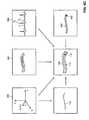
- FIG. 1Ais a schematic illustration of a graphical user interface (GUI) displaying a representation of a medical device on a two-dimensional image of a lumen system of the body of a patient, constructed and operative according to an embodiment of the disclosed technique;
- GUIgraphical user interface
- FIG. 1Bis a schematic illustration of a GUI displaying another representation of the medical device on a three-dimensional image of a lumen of the lumen system of FIG. 1A , constructed and operative according to another embodiment of the disclosed technique;
- FIG. 2Ais a schematic illustration of the GUI of FIG. 1A , displaying a set of marks respective of a selected position within the lumen system and a representation of the current position of the medical device advancing toward the selected location, on the two-dimensional image of FIG. 1A ;
- FIG. 2Bis a schematic illustration of the GUI of FIG. 1B , displaying another set of marks equivalent to the set of marks of FIG. 2A , and another representation of the current position of the medical device, on the three-dimensional image of FIG. 1 B;
- FIG. 3Ais a schematic illustration of the GUI of FIG. 1A when the medical device reaches the selected position;
- FIG. 3Bis a schematic illustration of the GUI of FIG. 1B when the medical device reaches the selected position;
- FIG. 4Ais a schematic illustration of a two-dimensional image of the lumen of FIG. 1A , at activity-state T 1 of an inspected organ;
- FIG. 4Bis a schematic illustration of another two-dimensional image of the lumen of FIG. 1A at activity-state T 2 ;
- FIG. 4Cis a schematic illustration of a further two-dimensional image of the lumen of FIG. 1A at activity-state T 3 ;
- FIG. 4Dis a schematic illustration of a GUI which includes a real-time substantially stabilized representation of an MPS sensor of a catheter located within the lumen of FIG. 1A , superimposed on the lumen of FIG. 4B , the GUI being constructed and operative according to a further embodiment of the disclosed technique;
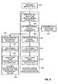
- FIG. 5is a schematic illustration of a method for delivering a medical device to a selected position within a lumen of the body of a patient, operative according to another embodiment of the disclosed technique;
- FIG. 6Ais a schematic illustration of an ECG of a patient
- FIG. 6Bis a schematic illustration of trajectories of the tip of a catheter located within the lumen of FIG. 1A , respective of different activity-states of the ECG of FIG. 6A , constructed according to another embodiment of the disclosed technique;
- FIG. 6Cis a schematic illustration of the process of reconstructing a three-dimensional organ motion dependent image sequence, and superimposing additional visual data thereon, by processing the signals received from the two-dimensional image acquisition device, the MPS and the ECG monitor;
- FIG. 7is a schematic illustration of an ECG coordinated display (i.e., a GUI) of a lumen, constructed and operative in accordance with a further embodiment of the disclosed technique;
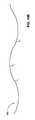
- FIG. 8Ais an illustration of the lumen of FIG. 1A , having a plurality of occluded regions.
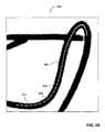
- FIG. 8Bis a cross-sectional view of a selected region of the lumen of FIG. 8A ;
- FIG. 8Cis a schematic illustration of a representation of the lumen of FIG. 8B in a GUI, operative in accordance with another embodiment of the disclosed technique;
- FIG. 9is a schematic illustration of a method for determining an organ timing signal of an organ of the patient, according to position data of an MPS sensor which moves together with the movements of the organ, operative in accordance with a further embodiment of the disclosed technique;
- FIG. 10Ais a schematic illustration of a cardiac trajectory, in an electrical signal representation and in a mechanical signal representation
- FIG. 10Bis a schematic illustration of a respiratory trajectory in a mechanical signal representation
- FIG. 11is a schematic illustration of a system for automatically maneuvering a catheter within a lumen of the body of a patient, constructed and operative in accordance with another embodiment of the disclosed technique.
- FIG. 12is a schematic illustration of a method by which the imaging system of the system of FIG. 11 determines the coordinates of a path within the lumen, in three dimensions.
- FIG. 13is a schematic illustration of a system constructed and operative in accordance with a further embodiment of the disclosed technique
- FIG. 14Ais a schematic illustration of a first image of a lumen of the body of the patient of FIG. 13 , acquired by the image acquisition device of the system of FIG. 13 , from a first viewing direction, at a marking stage;
- FIG. 14Bis a schematic illustration of a second image of the lumen of FIG. 13 , acquired by the image acquisition device of the system of FIG. 13 , from a second viewing direction, at the marking stage;
- FIG. 15Ais a schematic illustration of a real-time two-dimensional image of the lumen of the patient of FIG. 13 , during visual maneuvering of the catheter of FIG. 13 , toward a selected position within the lumen;
- FIG. 15Bis a schematic illustration of a real-time three-dimensional image of the lumen, during automatic maneuvering of the catheter toward the selected position within the lumen;
- FIG. 16Ais a schematic illustration of the lumen of FIG. 15A , when the medical device located at tip of the catheter, has reached the selected position;
- FIG. 16Bis a schematic illustration of the lumen of FIG. 15B , when the medical device has reached the selected position;
- FIG. 17which is a schematic illustration of a method for operating the system of FIG. 13 , according to another embodiment of the disclosed technique;
- FIG. 18is a schematic illustration of a system for producing a markable image, constructed and operative in accordance with a further embodiment of the disclosed technique
- FIG. 19is a schematic illustration of a method for operating the system of FIG. 18 ;
- FIG. 20is a schematic illustration of the markable image produced by the system of FIG. 18 .
- the disclosed techniqueovercomes the disadvantages of the prior art by graphically designating on an image of the lumen, the position where a medical device (e.g., a PCI device, a dilation balloon, a stent delivery system) has to be delivered, and indicating when the medical device has reached the selected position.
- a medical devicee.g., a PCI device, a dilation balloon, a stent delivery system
- the medical deviceis attached to the tip of a catheter.
- a medical positioning system (MPS) sensorconstantly detects the position of the medical device relative to the selected position.
- MPSmedical positioning system
- This positionis represented on a real-time image (e.g., live fluoroscopy), a pseudo-real-time image (e.g., previously recorded cine-loop) or a previously recorded still image frame of the lumen, thereby obviating the need to radiate the inspected organ of the patient repeatedly, neither or to repeatedly inject contrast agent to the body of the patient.
- the medical staffcan either guide the catheter manually according to feedback from an appropriate user interface, such as display, audio output, and the like, or activate a catheter guiding system which automatically guides the catheter toward the selected position.
- positionrefers to the location of a point in space, the orientation of the point in space, or a combination thereof.
- the term “lumen” herein belowrefers to an organic tubular structure of the human patient or the operated animal, such as an artery, vein, cardiac vessel, brain vessel, part of the urogenital system, nephrotic system, hepatic system, bronchus tree, and the like.
- the term “medical device” herein belowrefers to one which is employed to perform a minimally invasive operation within a lumen of the body of a patient.
- the medical devicecan be a vessel expansion unit such as a dilation balloon, stent delivery system, balloon expanding stent, self expending stent, percutaneous valve system, percutaneous coronary intervention (PCI) device, an ablation unit such as laser, cryogenic fluid unit, electric impulse unit, cutting balloon, rotational atherectomy unit (i.e., rotablator), directional atherectomy unit, transluminal extraction unit, a substance delivery unit such as coated or drug eluting metal stent, bio-absorbable stent, drug delivery balloon, brachytherapy unit, guidewire, and the like.
- stentand “PCI device” herein below, are provided as two different examples of a “medical device”.
- organ timing signalrefers to a signal representing cardiac cycle of the heart or the respiratory cycle of the lungs.
- An organ timing signalcan be extracted using traditional methods such as ECG monitor, respiration rate monitor, and the like, herein below referred to as “organ timing signal monitor”.
- the organ timing signalcan be acquired by measuring the movements of the lumen due to cardiac or respiratory cycles. The movements of the lumen due to the cardiac or the respiratory cycle, can be measured by the MPS sensor attached to the catheter. In this case, the MPS determines the respective organ timing signal, according to the method described herein below in connection with FIG. 9 .
- the term “cine-loop” herein belowrefers to a prerecorded sequence of two-dimensional images of the lumen, which are played back over and over again (i.e., in a loop), in synchrony with the real-time organ timing signal of the inspected organ of the patient.
- the two-dimensional imagesare acquired by a two-dimensional image acquisition device, such as X-ray fluoroscopy, C-arm, and the like, and individually stored while being associated with the respective activity-state of the inspected organ, at the time of image acquisition.
- an angiogramis produced by acquiring the two-dimensional images, while a contrast agent, injected into the body of the patient, is in an active state.
- the term “perspective” herein belowrefers to an image of the lumen, which is acquired from different viewing angles, acquired by a plurality of image acquisition devices of different types, acquired by a plurality of image acquisition devices of substantially identical types, or a combination thereof.
- image sequencerefers to a sequence of images of the lumen of the patient, acquired by an image acquisition device coupled with a processor.
- each image acquisition deviceacquires a different set of image sequences.
- the processorcan produce a still image of the lumen, by selecting an image among one of the image sequences.
- the image sequencecan be two-dimensional (i.e., acquired by a two-dimensional image acquisition device).
- the navigation imagecan be either two-dimensional or three-dimensional.
- the navigation imagecan be either a still image, a real-time image, or a cine-loop of the lumen system.
- the image sequencecan be three-dimensional.
- the processorproduces a three-dimensional image sequence by reconstructing a plurality of two-dimensional images, according to the organ timing signal of the inspected organ, and according to position data respective of the coordinates of each two-dimensional image, which the MPS determines according to an output of an MPS sensor.
- the processorcan produce a still image (i.e., either two-dimensional or three-dimensional) of the lumen, by selecting an image among one of the image sequences.
- real-time imagerefers to an image which the operator views in real-time in order to maneuver the catheter within the lumen system.
- the real-time imageshows the lumen system with the catheter therein, in real-time.
- the real-time imagecan be either two-dimensional or three-dimensional.
- medical positioning systemMPS
- MPSmedical positioning system
- FIG. 1Ais a schematic illustration of a graphical user interface (GUI) generally referenced 100 , displaying a representation of a medical device on a two-dimensional image of a lumen system of the body of a patient, constructed and operative according to an embodiment of the disclosed technique.
- FIG. 1Bis a schematic illustration of a GUI generally referenced 102 , displaying another representation of the medical device on a three-dimensional image of a lumen of the lumen system of FIG. 1A , constructed and operative according to another embodiment of the disclosed technique.
- FIG. 2Ais a schematic illustration of the GUI of FIG.
- FIG. 1Adisplaying a set of marks respective of a selected position within the lumen system and a representation of the current position of the medical device advancing toward the selected location, on the two-dimensional image of FIG. 1A .
- FIG. 2Bis a schematic illustration of the GUI of FIG. 1B , displaying another set of marks equivalent to the set of marks of FIG. 2A , and another representation of the current position of the medical device, on the three-dimensional image of FIG. 1B .
- FIG. 3Ais a schematic illustration of the GUI of FIG. 1A when the medical device reaches the selected position.
- FIG. 3Bis a schematic illustration of the GUI of FIG. 1B when the medical device reaches the selected position.
- GUI 100includes a two-dimensional image 104 of the lumen system, as detected by the respective two-dimensional image acquisition device.
- Two-dimensional image 104can be an X-ray fluoroscopy, (i.e., angiogram), ultrasound image, an image detected by an optical coherent tomography detector—OCT, and the like.
- X-ray fluoroscopy or angiogramtwo-dimensional image 104 is a real-time image which is acquired from the lumen system, while a contrast agent is present in the lumen system.
- the ultrasound imageis acquired during pull-back of the catheter within the same lumen system, which is known in the art as a virtual intravascular ultrasound (i.e., virtual IVUS) image.
- the virtual IVUS imagecan be displayed together with a real-time image of the lumen system.
- the virtual IVUS imagecan be either a still image of the lumen system, or a cine-loop thereof (i.e., an image sequence).
- the virtual IVUS image of the lumen systemcorresponds to the current position of the catheter within the lumen system, as detected by an MPS sensor (not shown), located at the tip of the catheter.
- This virtual IVUS imagecan be displayed at a selected phase of the organ timing signal of an organ (not shown) of the patient.
- two-dimensional image 104can be either a real-time image, a still image, or a cine-loop.
- the cine-loopcan be acquired from a viewing angle different than the real-time image, thereby providing the operator with a real-time view of the lumen system from one viewing angle and a cine-loop view (i.e., a navigation image) from a different viewing angle of the same portion of the lumen system (i.e., bi-plane mode operation).
- the bi-plane modecan include two cine-loops each acquired from two different viewing angles, thereby providing the operator with two cine-loops acquired from two different viewing angles. It is noted that more than two different sets of images from more than two different viewing angles can be employed, thereby enabling a multi-plane operation mode.
- Two-dimensional image 104can be a still image of the lumen system (i.e., one of the images among a plurality of images in a cine-loop, which the operator selects).
- the selected two-dimensional imagecan be an image whose contrast for example, is better (e.g., the difference in the brightness of the dark pixels and the bright pixels in the image, is large) than all the rest, and which portrays the lumen system in a manner which is satisfactory for the operator either to designate the selected location of the medical device, or to view a real-time representation of the stent, as the medical device is being navigated within the lumen system.
- GUI 102includes a three-dimensional image 106 of a lumen (referenced 108 ) of the lumen system displayed in GUI 100 , through which the catheter is being maneuvered.
- Three-dimensional image 106is reconstructed from a plurality of two-dimensional images which are detected by a two-dimensional image acquisition device, during an image acquisition stage, by a technique known in the art.
- Three-dimensional image 106is a three-dimensional cine-loop (i.e., a navigation image) of lumen 108 , which is played back in a loop, in synchrony with the real-time organ timing signal of the inspected organ.
- three-dimensional image 106is a still image of lumen 108 , which is selected among a plurality of three-dimensional images in the cine-loop. The operator can select the still image by playing the cine-loop forward and backward.
- three-dimensional image 106is a still image of lumen 108 , frozen at a selected activity-state of the inspected organ.
- Three-dimensional image 106is synchronized with a real-time organ timing signal (e.g., cardiac cycle) respective of the movement of the inspected organ (e.g., the inspected lumen—not shown).
- the organ timing signalcan be acquired for example, by an ECG monitor (not shown) coupled with the patient.
- the organ timing signale.g., the heart beat or the respiration of the patient
- the MPScan be determined by the MPS (not shown), as described herein below in connection with FIGS. 9 , 10 A, and 10 B.
- a systemcan display a selected image sequence (either a sequence of two-dimensional images detected by the respective two-dimensional image acquisition device, or a sequence of three-dimensional images reconstructed from a plurality of two-dimensional images—i.e., a cine-loop or video clip), in synchrony with the real-time organ timing signal of the patient, among a list of prerecorded image sequences.
- the systemcan display a still image among a selected image sequence.
- the systemcan display a real-time two-dimensional image of the inspected organ, acquired from a first viewing angle by one of the two-dimensional image acquisition devices, alongside a navigation two-dimensional image sequence (i.e., two-dimensional cine-loop) of the inspected organ, acquired previously by either the same two-dimensional image acquisition device or another two-dimensional image acquisition device, from a second viewing angle, and played back in synchrony with the real-time organ timing signal of the inspected organ.
- a navigation two-dimensional image sequencei.e., two-dimensional cine-loop
- the operatorcan view a prerecorded two-dimensional image sequence (e.g., an X-ray fluoroscopy) synchronized with the real-time organ timing signal of the organ, thereby obviating the need to inject a contrast agent repeatedly and subjecting the patient and the operator to unnecessary radiation.
- a prerecorded two-dimensional image sequencee.g., an X-ray fluoroscopy
- the systemcan display the image relative to a selected activity-state of the organ (i.e., a still image), as described herein below in connection with FIG. 7 .
- An MPS sensor(not shown) is firmly attached to the tip of the catheter.
- Three-dimensional image 106is registered with two-dimensional image 104 , such that each point in two-dimensional image 104 corresponds to a respective point in three-dimensional image 106 .
- the coordinates of each point in three-dimensional image 106can be projected onto two-dimensional image 104 .
- each point in two-dimensional image 104can be transferred to three-dimensional image 106 (e.g., by acquiring a series of two-dimensional images from different viewing angles).
- a real-time representation 110 ( FIG. 1A ) of the MPS sensoris superimposed on lumen 108 , as described herein below in connection with FIG. 6C .
- a real-time representation 112 ( FIG. 1B ) of the MPS sensoris superimposed on three-dimensional image 106 .
- the operatorcan view one or more radio-opaque markers (e.g., metallic band) attached to the catheter, on a real-time two-dimensional image of lumen 108 .
- radio-opaque markerse.g., metallic band
- This featureenables the operator to continue using the real-time two-dimensional image, even when little or no contrast agent exists within lumen 108 , or when the contrast agent within lumen 108 is unnoticeable.
- a trajectory 114 ( FIG. 1B ) of the catheter as advanced through lumen 108is constructed and represented in GUI 102 , as described herein below in connection with FIGS. 6B , and 6 C.
- Trajectory 114is constantly updated in synchrony with the movement of lumen 108 , according to the position data acquired by the MPS sensor.
- three-dimensional image 106is displayed relative to the coordinate system of lumen 108 .
- the movement of lumen 108can be caused for example, by the heart beat, the respiration, contraction of nearby muscles of the patient, and the like.
- the operatorcan direct the system via a user interface (not shown), to alternately display GUI 100 and GUI 102 , on the display.
- the user interfacecan be a switch, foot pedal, and the like, as described herein below in connection with FIG. 4D .
- the displaycan display GUI 100 and GUI 102 at the same time, side by side.
- the systemcan include a plurality of displays coupled with the processor, each display displaying different image sequences. The operator can direct the system to display a real-time two-dimensional image of the lumen system, for example, by pressing the foot pedal, thereby activating the respective two-dimensional image acquisition device.
- the operatorcan direct the system via the user interface, to display a previous two-dimensional cine-loop of the lumen system, instead of the real-time two-dimensional image of the lumen system.
- the systemdisplays the two-dimensional cine-loop which was last played back. If the system includes no cine-loops (i.e., prerecorded time-tagged image sequences), then the system displays a cine-loop of the most recent real-time two-dimensional image. Further alternatively, the operator can direct the system to display the real-time two-dimensional image and a selected cine-loop, on the same display, side by side.
- GUI 100 and GUI 102the operator maneuvers the catheter manually, in order to reach a predetermined region within the lumen system.
- the operatorcan employ an automatic system (not shown) for automatically maneuvering the catheter to the predetermined region, as described herein below in connection with FIGS. 11 , and 12 .
- the operatorgraphically designates a plurality of marks 116 , 118 , and 120 on two-dimensional image 104 , as a selected position within lumen 108 , which a medical device (not shown) is to be delivered to.
- the operatorperforms the marking either on a frozen two-dimensional image of lumen 108 , or on a frozen reconstructed three-dimensional model of lumen 108 .
- the operatorperforms the marking in different manners, such as manually, according to an automated two-dimensional or three-dimensional quantitative cardiac assessment (QCA), and the like.
- QCAquantitative cardiac assessment
- a respective one of a plurality of displaysdisplays a superposition of a trajectory of a catheter previously maneuvered through lumen 108 , on an image of lumen 108 .
- the trajectorycan be displayed either on two-dimensional image 104 or three-dimensional image 106 (e.g., trajectory 114 ).
- the GIVUSis a catheter which includes an image detector (e.g., ultrasound transducer) at the tip thereof, and an MPS sensor in the vicinity of the image detector.
- the operatormaneuvers the GIVUS within the lumen, as far as physically possible, and then pulls the GIVUS back through the lumen.
- the image detectordetects a plurality of two-dimensional images of the inside of the lumen.
- the systemassociates each of the two-dimensional images with the respective position of the image detector determined by the MPS, and with the respective activity-state of the inspected organ.
- the systemcan determine a cine-loop of the trajectory during the pull-back, and the operator can select a frozen trajectory to be employed during the planning session.
- the systemcan further reconstruct three-dimensional image 106 according to the time-tagged two-dimensional images acquired by the GIVUS.
- a respective one of the displaysdisplays marks 116 , 118 and 120 articulated by the user interface on an image of lumen 108 .
- the operatorcan move marks 116 , 118 and 120 together along the full length of the trajectory (e.g., trajectory 114 of FIG. 1B ).
- Mark 118designates the middle of the medical device, while marks 116 and 120 designate the rear end and the front end of the medical device, respectively.
- the systemdetermines the distance between marks 116 and 120 , according to the type (e.g., the size of stent) which the operator has selected.
- Marks 116 , 118 and 120 togetherare locked-on to the trajectory, while being operative to travel along the trajectory.
- the operatordesignates the position of mark 118 along the trajectory where the medical device is to be delivered to.
- the medical device in the example set forth in FIGS. 2A , 2 B, 3 A, and 3 Bis a stent.
- each of marks 116 , 118 , and 120is a substantially straight line, which is substantially perpendicular to lumen 108 .
- marks 116 and 120designate the two ends of the stent, while mark 118 designates the middle of the stent.
- Marks 116 , 118 , and 120define the location of the stent in lumen 108 , as well as the orientation thereof.
- the markingis performed via a user interface (not shown), such as a joystick, push button, pointing device (e.g., a mouse, stylus and digital tablet, track-ball, touch pad), and the like.
- a plurality of marks 122 , 124 and 126which are the counterpart of marks 116 , 118 , and 120 , respectively, are simultaneously displayed on three-dimensional image 106 in GUI 102 .
- each of two-dimensional image 104 and three-dimensional image 106is frozen at the same activity-state of the inspected organ (e.g., the heart). This freezing feature provides a still image of lumen 108 , thereby preventing vibrations of the image and enabling a successful marking by the operator.
- an algorithmcan be employed to automatically identify the selected location (e.g., by entering into the algorithm, a selected percentage of occlusion by a plaque in a lumen), and designate marks 116 , 118 , 120 , 122 , 124 , and 126 , automatically.
- This aspect of the inventionis described herein below in connection with FIGS. 8A , 8 B, and 8 C.
- the systemassociates the occlusion data with three-dimensional image 106 , and projects this occlusion data on two-dimensional image 104 , for the purpose of designating marks 116 , 118 and 120 .
- a catheterwhich includes a stent (not shown), is maneuvered within lumen 108 toward marks 116 , 118 and 120 .
- An MPS sensor(not shown) is attached to the catheter in the vicinity of the stent.
- FIGS. 2A and 2Bthe position of the front end and of the rear end of the stent are represented in real-time, by features 128 and 130 , respectively, on two-dimensional image 104 , and by features 132 and 134 , respectively, on three-dimensional image 106 . In the example set forth in FIGS.
- each of features 128 and 130is in form of a rectangle with longitudinal lines 136 and 138 , respectively, dividing each rectangle in two.
- the actual trajectory of the catheteris represented by a feature 140 ( FIG. 2B ) superimposed on three-dimensional image 106 .
- the actual trajectory of the cathetercan be represented by another feature (not shown) superimposed on two-dimensional image 104 .
- the systemsuperimposes features 128 and 130 together with marks 116 , 118 and 120 , while the catheter is being maneuvered through lumen 108 , either on a real-time two-dimensional image of lumen 108 (e.g., angiogram), on a two-dimensional cine-loop of lumen 108 , or on a frozen two-dimensional image of lumen 108 .
- a real-time two-dimensional image of lumen 108e.g., angiogram
- the systemsuperimposes features 132 and 134 together with marks 122 , 124 and 126 , while the catheter is being maneuvered through lumen 108 , either on a real-time three-dimensional image of lumen 108 , on a still three-dimensional image of lumen 108 , or on a cine-loop of lumen 108 . Further additionally, the system superimposes features 132 and 134 together with marks 122 , 124 and 126 , on the real-time two-dimensional image of lumen 108 , as well as one or more navigation images of lumen 108 (e.g., virtual IVUS image—either a still image or a cine-loop), acquired from viewing angles different than that of the real-time two-dimensional image.
- one or more navigation images of lumen 108e.g., virtual IVUS image—either a still image or a cine-loop
- the systemdetermines the distance between the centers (not shown) of features 128 and 130 , according to the type (i.e., size) of stent which the operator selects for mounting in lumen 108 .
- This distance as displayed on the respective one of the displaysis substantially fixed, as the stent is maneuvered through lumen 108 .
- Features 128 and 130move together on image 104 , while the stent is maneuvered through lumen 108 .
- a respective one of the displayscan display trajectories 140 and 142 , either while a catheter (not shown) is being maneuvered through lumen 108 , or during a play-back session, after performing the medical operation on the patient.
- the systemsuperimposes features 128 , 130 , 132 , and 134 , and marks 116 , 118 , 120 , 122 , 124 , and 126 , on the respective image of lumen 108 , according to the real-time organ timing signal of the inspected organ (i.e., the system takes into account the movements of lumen 108 due to the movements of the inspected organ, while the catheter is being maneuvered through lumen 108 ).
- This aspect of the disclosed techniqueenables the system to display marks 116 , 118 , 120 , 122 , 124 , and 126 , on a vibrating image of lumen 108 , at substantially the same position which the operator had initially designated relative to lumen 108 .
- marks 116 , 118 , 120 , 122 , 124 , and 126would be non-stationary relative to a vibrating image of lumen 108 .
- features 128 , 130 , 132 , and 134are substantially stationary relative to the vibrating image of lumen 108 .
- the operatorcan direct the system to either turn on or turn off the display of superposition of any of the marks, the representation of the position of the stent, the trajectory, or a combination thereof, via the user interface.
- Any attributecan be selected to represent the marks and the representation of the stent, as long as they are different, such as color, shape, size, and the like.
- a mark or a stent representationis displayed by the same attribute both in two-dimensional image 104 and three-dimensional image 106 .
- marks 116 , 118 , 120 , 122 , 124 , and 126are represented in green
- features 128 , 130 , 132 , and 134are represented in blue
- trajectory 140is represented in red.
- each of two-dimensional image 104 and three-dimensional image 106is displayed relative to the coordinate system of lumen 108 (i.e., relative to the MPS sensor which is attached to the catheter, and which constantly moves together with lumen 108 ).
- a user interfacee.g., audio, visual, or tactile device—not shown announces the event to the operator.
- each pair of longitudinal lines and marksturns into a cross (i.e., longitudinal line 136 together with mark 120 forms one cross, and longitudinal line 138 together with mark 116 forms another cross).
- the user interfacecan produce a relatively weak output, or a relatively strong output, when the stent is receding from the selected location, or approaching the selected location, respectively.
- the volume of the audio signalis increased, and otherwise, the volume is decreased.
- a trajectory of the catheter while being maneuvered toward the selected locationis represented by a feature referenced 142 ( FIG. 3B ) superimposed on three-dimensional image 106 .
- FIG. 4Ais a schematic illustration of an image, generally referenced 144 , of the lumen of FIG. 1A , at activity-state T 1 of an inspected organ.
- FIG. 4Bis a schematic illustration of another image, generally referenced 146 , of the lumen of FIG. 1A at activity-state T 2 .
- FIG. 4Cis a schematic illustration of a further image, generally referenced 148 , of the lumen of FIG. 1A at activity-state T 3 .
- FIG. 4Dis a schematic illustration of a GUI generally referenced 150 , which includes a real-time substantially stabilized representation of an MPS sensor of a catheter located within the lumen of FIG. 1A , superimposed on the lumen of FIG. 4B , the GUI being constructed and operative according to a further embodiment of the disclosed technique.
- Images 144 , 146 , and 148 in the description herein belowcan be either a two-dimensional image or a three-dimensional image.
- Images 144 , 146 and 148belong to a set of images of lumen 108 ( FIG. 1A ), acquired prior to the planning session.
- lumen 108 at activity-state T 2represented by a point 152 has moved by a distance S 1 along the negative Y axis, relative to the position thereof at activity-state T 1 .
- lumen 108 at activity-state T 3has moved by a distance S 2 along the negative Y axis, relative to the position thereof at activity-state T 2 .
- the contrast agent which is injected into the lumen system of the patientremains within lumen 108 for a substantially short period of time. During this period of time, the contrast of the set of the images gradually increases to a peak and then gradually decreases, until the image disappears altogether.
- the operatorselects one of the images 144 , 146 and 148 (e.g., image 146 ), in order to designate marks 116 , 118 and 120 ( FIG. 2A ), and later observes the real-time advancement of the catheter represented by features 128 and 130 , superimposed on image 146 .
- Image 146is an image of lumen 108 at activity-state T 2 .
- the systemcompensates for the movement of lumen 108 due to the cycle of the inspected organ (e.g., the cardiac cycle), in order to superimpose a substantially static real-time representation of the medical device on an image (not shown) of lumen 108 , which is also substantially static.
- the systemproduces the image in the coordinate system of the MPS sensor which is attached to the catheter.
- the operatorcan view a substantially static image of lumen 108 , along with the real-time substantially static representation of the medical device, despite the actual movements of lumen 108 due to the cycle of the inspected organ. It is noted that in the absence of this technique, the operator would view an unstable rapidly vibrating image of lumen 108 , together with the real-time representation of the medical device, which is distracting to the eyes.
- GUI 150displays a real-time representation 154 of the medical device superimposed on an image of lumen 108 frozen at activity-state T 2 , while representation 154 is substantially static at all activity-states, including activity-states T 1 and T 2 .
- the systemproduces image 146 in a presentation coordinate system, in which the MPS sensor is substantially stationary (e.g., the stent is fixed in the center of the image, while the scenery around it changes, as the stent is moved within the lumen). It is noted that according to this aspect of the disclosed technique, the system is capable to display a substantially static representation of the medical device, substantially free of vibrations due to the cardiac cycle.
- representation 154maintains a superposition of representation 154 on the image of lumen 108 , within the boundaries of that image, while the catheter is maneuvered through lumen 108 .
- representation 154would erratically move back and forth between points 156 and 158 (corresponding to distances S 1 and S 2 , respectively), which are distracting to the operator.
- the systemcan superimpose only that representation of the medical device, which corresponds to the activity-state respective of the frozen image of lumen 108 , and neglect all other activity-states of lumen 108 .
- the systemcan superimpose representation 154 on the image of lumen 108 , only when representation 154 corresponds to activity-state T 2 .
- This type of displaystill provides a substantially satisfactory view for the operator, since for example, at substantially rapid rates of the cardiac cycle, this loss of data is substantially imperceptible to the human eye.
- the systemcan determine the distances S 1 and S 2 , according to a set of three-dimensional images reconstructed from a series of time-tagged two-dimensional images of lumen 108 , acquired from inside of lumen 108 (e.g., by employing a GIVUS). Alternatively, the system can determine the distances S 1 and S 2 by processing and comparing among a set of two-dimensional images acquired from outside of lumen 108 (e.g., images 144 , 146 and 148 ).
- the operatorcan direct the system to switch between GUI 150 and a real-time two-dimensional image of lumen 108 (e.g., an angiogram), by employing a user interface (not shown—for example a foot pedal).
- a user interfacenot shown—for example a foot pedal.
- the two-dimensional image acquisition deviceradiates a portion of the body of the patient, and the system displays the real-time two-dimensional image instead of GUI 150 .
- the systemcan superimpose the real-time two-dimensional image on GUI 150 .
- the systemcan display the real-time two-dimensional image along side GUI 150 .
- FIG. 5is a schematic illustration of a method for delivering a medical device to a selected position within a lumen of the body of a patient, operative according to another embodiment of the disclosed technique.
- procedure 160position data respective of a selected position within a lumen of the body of a patient is received, the position data being associated with an image of the lumen, the image being associated with a coordinate system, the coordinate system being further associated with a medical positioning system (MPS).
- MPSmedical positioning system
- a processor of a systemreceives via a user interface, position data respective of marks 116 , 118 and 120 , which the operator designates on two-dimensional image 104 .
- Marks 116 , 118 and 120designate the selected position within lumen 108 , where the medical device is to be delivered to.
- Marks 116 , 118 , and 120are associated with two-dimensional image 104
- two-dimensional image 104is associated with a coordinate system
- the coordinate systemis further associated with the MPS.
- the processordetermines the coordinates of marks 116 , 118 and 120 , in the MPS coordinate system (procedure 162 ).
- the processorfurther determines the coordinates of marks 122 , 124 , and 126 on three-dimensional image 106 , in the MPS coordinate system, which are equivalent to marks 116 , 118 , and 120 , respectively (procedure 162 ).
- procedure 164at least one image sequence in selected from a plurality of image sequences, each of the image sequences being acquired from a different perspective.
- the processorselects an image sequence among a plurality of image sequences, each acquired by a different image acquisition device, from a different viewing angle, or a combination thereof.
- the current position of a medical device in an MPS coordinate systemis determined.
- the MPSdetermines the current position of the medical device, in the MPS coordinate system, according to the output of the MPS sensor. This current position is represented by real-time representation 110 .
- a navigation image of the lumenis produced, according to the selected image sequence, and according to a real-time organ timing signal respective of an organ of the patient.
- the processorproduces two-dimensional image 104 according to the image sequence which the processor selects in procedure 164 , and according to the real-time organ timing signal of an organ of the patient (e.g., the heart).
- the processorproduces three-dimensional image 106 in a similar manner.
- procedure 170a marking representation respective of the selected position, and a current position representation respective of the current position of the medical device, is superimposed on the navigation image, thereby producing a superimposed image.
- the processorproduces two-dimensional image 104 , by superimposing marks 116 , 118 , and 120 , and further superimposing features 128 and 130 representative of the current position of the medical device, on the navigation image which the processor produces in procedure 168 .
- the processorproduces three-dimensional image 106 in a similar manner.
- the catheteris maneuvered through the lumen, toward the selected position, according to the current position of the medical device, relative to the selected position.
- the operatormaneuvers the catheter toward the selected position, manually, by viewing features 128 and 130 on the display, as well as marks 116 , 118 , and 120 .
- the operatormaneuvers the catheter automatically or semi-automatically toward the selected position, as described herein below, in connection with FIG. 11 .
- the processorproduces a notification output, when the processor determines that the current position of the medical device substantially matches the selected position (procedure 174 ).
- procedure 164can be eliminated from the above mentioned method.
- the processorproduces the navigation image according to a single image sequence, where there is no provision for the operator to view different images of lumen 108 acquired from different viewing angles or by different image acquisition devices.
- procedures 164 , 168 and 170are optional, wherein procedure 172 is performed without any visual aid to represent the lumen in which the catheter is maneuvered (i.e., analogous to instrument flying with zero visibility).
- a systemcan produce three-dimensional image 106 according to a plurality of two-dimensional images acquired by a two-dimensional image acquisition device, and according to the organ timing signal of lumen 108 , and play back an image sequence of the three-dimensional image 106 in synchrony with the real-time organ timing signal.
- the systemcan play back also a cine-loop of lumen 108 in synchrony with the real-time organ timing signal, selected from a list of cine-loops.
- the systemcan display either of two-dimensional image 104 or three-dimensional image 106 , relative to a selected activity-state of the organ timing signal (i.e., freezing an image).
- the systemcan display either of two-dimensional image 104 or three-dimensional image 106 , relative to the coordinate system of a selected MPS sensor (e.g., an MPS sensor attached to the catheter, an MPS sensor attached to the body of the patient, or an MPS attached to the operating table).
- the systemcan display a still image selected from a cine-loop sequence.
- the systemcan acquire the organ timing signal by processing the MPS data, instead of the data acquired by the ECG monitor.
- the systemcan display a representation of the position of the catheter superimposed on either two-dimensional image 104 , or three-dimensional image 106 , as well as the actual trajectory of the catheter within the lumen.
- the systemcan identify a plaque within lumen 108 , having a selected percentage of occlusion, and automatically designate the position of the plaque by marks 116 , 118 and 120 .
- the two-dimensional image acquisition devicecan be of any type known in the art, such as computerized tomography (CT), nuclear magnetic resonance (MRI), positron-emission tomography (PET), single-photon-emission computer tomography (SPECT), fluoroscopy (i.e., X-ray machine), C-arm, guided intra-vascular ultrasound (GIVUS), external ultrasound, optical coherent tomography (OCT) detector, and the like.
- CTcomputerized tomography
- MRInuclear magnetic resonance
- PETpositron-emission tomography
- SPECTsingle-photon-emission computer tomography
- fluoroscopyi.e., X-ray machine
- C-armguided intra-vascular ultrasound (GIVUS)
- GIVUSguided intra-vascular ultrasound
- OCToptical coherent tomography
- a trajectory corresponding to the selected activity-statecan be displayed together with the three-dimensional image of the lumen corresponding to the same activity-state.
- a real-time three-dimensional image sequence of the lumencan be displayed according to the organ timing signal of the lumen, together with the corresponding trajectories.
- FIG. 6Ais a schematic illustration of an ECG of a patient, generally referenced 300 .
- FIG. 6Bis a schematic illustration of trajectories of the tip of a catheter located within the lumen of FIG. 1A , respective of different activity-states of an ECG 6 A, constructed according to another embodiment of the disclosed technique.
- FIG. 6Cis a schematic illustration of the process of reconstructing a three-dimensional organ motion dependent image sequence, and superimposing additional visual data thereon, by processing the signals received from the two-dimensional image acquisition device, the MPS and the ECG monitor.
- the additional visual datacan include the position of the catheter within the lumen, the trajectory of a catheter within the lumen, and the like.
- ECG 300includes a plurality of activity-states (e.g. ECG cycle phases), such as activity-states T 1 , T 2 and T 3 in each of a plurality of heart cycles 302 , 304 and 306 .
- activity-statese.g. ECG cycle phases
- FIGS. 1A and 1Bthe position of lumen 108 is different at different activity-states, during each of the heart cycles 302 , 304 and 306 .
- the position of lumen 108is represented by a lumen image at a position 330 ( FIG. 6B ).
- the position of lumen 108is represented by a lumen image at a position 332 .
- the position of lumen 108is represented by a lumen image at a position 334 .
- points 336 , 338 and 340represent different positions of a catheter (not shown) at activity-state T 1 .
- points 342 , 344 and 346represent different positions of the catheter at activity-state T 2 .
- points 348 , 350 and 352represent different positions of the catheter at activity-state T 3 .
- a processorassociates between all of the two-dimensional images (i.e., images acquired at points 336 , 338 and 340 ) which were detected during activity-state T 1 at any cycle of ECG signal 300 .
- processor 192associates between all of the two-dimensional images (i.e., images acquired at points 342 , 344 and 346 ) which were detected during activity-state T 2 at any cycle of ECG 300 and further associates between all of the two-dimensional images (i.e., images acquired at points 348 , 350 and 352 ) which were detected during activity-state T 3 at any cycle of ECG 300 .
- the processorreconstructs a three-dimensional image from all of the two-dimensional images, which were associated with respect to a given activity-state T i .
- the processorreconstructs three-dimensional image 330 , which is the image of the inspected organ at activity-state T 1 ( FIG. 6A ), and three-dimensional image 332 , which is the image of the inspected organ at activity-state T 2 .
- the processorreconstructs three-dimensional image 334 , which is the image of the inspected organ at activity-state T 3 .
- the processorcalculates a trajectory 354 from points 336 , 338 and 340 , associated with activity-state T 1 . Similarly, the processor calculates a trajectory 356 from points 342 , 344 and 346 associated with activity-state T 2 and further calculates a trajectory 358 from points 348 , 350 and 352 associated with activity-state T 3 .
- the processorassociates between each of the calculated trajectories and one of the reconstructed three-dimensional images, respective of a given organ activity-state. With reference to FIG. 6B , the processor associates between trajectory 354 and reconstructed three-dimensional image 330 , respective of activity-state T 1 . Similarly, the processor associates between trajectory 356 and reconstructed three-dimensional image 332 , respective of activity state T 2 and further between trajectory 358 and reconstructed three-dimensional image 334 , respective of activity-state T 3 .
- the processorcan superimpose each of the calculated trajectories on its respective reconstructed three-dimensional image. For example, the processor superimposes trajectory 354 on three-dimensional image 330 , trajectory 356 on three-dimensional image 332 and trajectory 358 on three-dimensional image 334 .
- the processorreconstructs three-dimensional image 106 ( FIG. 1B ) of lumen 108 , from a plurality of two-dimensional images 380 , according to MPS coordinate data 382 , all of which are respective of a selected activity-state within the cycles of ECG data 384 .
- the processorreconstructs three-dimensional image 106 from all the two-dimensional images which belong to of activity-state T 2 .
- the processorgenerates trajectory 114 ( FIG. 1 B) of the catheter, which corresponds to activity-state T 2 , from points 342 , 344 and 346 ( FIG. 6B ).
- the processorsuperimposes trajectory 114 and real-time representation 112 ( FIG. 1B ) of a tip 390 of the catheter, on three-dimensional image 106 .
- a systemcan playback the sequence of reconstructed images or a selected cycle of the originally acquired two-dimensional images, according to the stored ECG data or at predetermined time intervals.
- the systemcan also playback the sequence of reconstructed images or a selected cycle of the originally acquired two-dimensional images, in synchrony with real-time detected ECG data.
- the processorhas to register the coordinate system in which the images were acquired, with the coordinate system of the MPS sensor of the catheter, or to use the same MPS system for the image acquisition process and the playback surgical procedure.
- GUIwhich allows the operator to freeze a three-dimensional image of a lumen, at a selected activity-state of an organ of the patient.
- the GUIalso allows the operator to move forward and backward in terms of activity-state.
- FIG. 7is a schematic illustration of an ECG coordinated display (i.e., a GUI) of a lumen, generally referenced 410 , constructed and operative in accordance with a further embodiment of the disclosed technique.
- ECG coordinated display 410includes an ECG timing signal 412 , a forward button 414 , a backward button 416 , a freeze button 418 and three-dimensional image 106 ( FIG. 1B ).
- Three-dimensional image 106corresponds with an activity-state 420 in ECG timing signal 412 .
- a sequence of three-dimensional images of lumen 108is displayed in a window 422 .
- Each of the three-dimensional images displayed in window 422corresponds with the respective activity-state in ECG timing signal 412 , as if ECG timing signal 412 would advance in a direction designated by an arrow 424 .
- a sequence of three-dimensional images of lumen 108is successively displayed in window 422 .
- Each of the three-dimensional images displayed in window 422corresponds with the respective activity-state in ECG timing signal 412 , as if ECG timing signal 412 would retard in a direction designated by an arrow 426 .
- a three-dimensional image of lumen 108is displayed in window 422 , wherein the three-dimensional image corresponds with a selected activity-state 428 .
- the three-dimensional image of lumen 108 in window 422remains stationary at activity-state 428 , during which the physician can inspect the three-dimensional image of lumen 108 .
- Each of the three-dimensional images, which are displayed in window 422is acquired by a system (not shown), during the scanning process.
- the operatorcan view animated three-dimensional images of lumen 108 as the heart of the patient would beat either forward or backward in time.
- the operatorcan alternatively view a three-dimensional image of lumen 108 , which corresponds with a selected activity-state during a selected heart cycle of the patient, by pressing freeze button 418 at a selected point in time.
- sequenced imagessuch as a reference real-time image (i.e., served as road map during navigation, such as a fluoroscopic image, and the like) can also be made to freeze-up.
- the processorautomatically designates the necessary marks on a real-time image of the lumen, as the selected position to which the medical device is to be delivered.
- FIG. 8Ais an illustration of the lumen of FIG. 1A , having a plurality of occluded regions.
- FIG. 8Bis a cross-sectional view of a selected region of the lumen of FIG. 8A .
- FIG. 8Cis a schematic illustration of a representation of the lumen of FIG. 8B in a GUI, generally referenced 450 , operative in accordance with another embodiment of the disclosed technique.
- Lumen 108includes plaques 452 , 454 and 456 . It is noted that plaques 452 , 454 and 456 can be fixed in their places or be dynamic. Plaques 452 , 454 and 456 block lumen 108 by 75%, 60% and 80%, respectively. With reference to FIG. 8B , the hatched area denotes the blockage due to plaque 452 within lumen 108 , leaving ducting 458 open for blood flow.
- a processor(not shown) can determine the percentage of occlusion, according to a plurality of methods, taking into account parameters such as plaque type, plaque density, and the like. The following is a simple example for such a method:
- % BLOCKED( 1 - S LUMEN S ARTERY ) ⁇ 100 where, S LUMEN denotes the cross section of ducting 458 and S ARTERY denotes the total internal area of lumen 108 .
- GUI 450includes a graphical window 460 .
- Graphical window 460includes three-dimensional image 106 and a ratio selection window 462 .
- Ratio selection window 462includes a graduation bar 464 , a pointer 466 and a numerical box 468 .
- the operatorcan dynamically set the occlusion percentage threshold, by dragging pointer 466 along graduation bar 464 , via a user interface (not shown).
- the operatorcan enter a selected occlusion percentage threshold in numerical box 468 , through the user interface.
- the numerical value 70%, of the selected percentageis shown in numerical box 468 .
- a system(not shown) then marks only those regions on three-dimensional image 106 , which are occluded more than the selected occlusion percentage.
- FIG. 8Bonly those regions of lumen 108 which are occluded 70% or more, are marked in three-dimensional image 106 .
- Plaques 452 and 456which exceed 70%, are represented by marked regions 470 and 472 , respectively, on three-dimensional image 106 .
- Marked regions 470 and 472are differentiated from the rest of the portions of three-dimensional image 106 , by being colored in a different hue, marked by hatches, animated, and the like.
- the systemenables the operator to manually correct the marking on screen, in case that the operator, according to her medical knowledge and experience detects for example, that the plaque portion should be different than what the system indicated. It is further noted that the system can present the various layers of the lumen (i.e., media, adventitia and intima), in GUI 450 , in different colors.
- time-taggingrefers to the process of associating a data element, with the exact time at which that data element was obtained (e.g., associating an MPS coordinate reading with the exact time at which that reading was obtained).
- the data obtained via a plurality of MPS sensorse.g., one attached to the tip of the catheter, one to the two-dimensional image acquisition device, one to the body of the patient, and one to an operation table
- 590 B, and 590 Care attached to the two-dimensional image acquisition device, there is no need to attach an MPS sensor to the two-dimensional image acquisition device.
- the reason in this caseis that the coordinate system of the two-dimensional image acquisition device is registered with that of the MPS.
- the two-dimensional images acquired by each two-dimensional image acquisition device(not shown) is also time-tagged. The time-tags are taken into account when processing the data elements stored in a database (not shown).
- Latency compensationis performed on all the time-tagged data elements.
- image frames from the set of two-dimensional (2D) images acquired by, the two-dimensional image acquisition deviceare shifted so that the time-tags thereof match the time-tag of the corresponding MPS data set (i.e., images acquired at the same time as an MPS coordinate reading was obtained will be matched with one another).
- corresponding data setsrefers to a pair of data sets which have the same time-tags. It is noted that the time-tag of a data set refers to the set of time-tags of the elements within the data set.
- an MPS data setis corresponding with a two-dimensional images data set if readings in the MPS data set have the same time-tag as the images in the two-dimensional images data set.
- Corresponding data setsrepresent data sets that occur during the same session in a medical procedure.
- an MPS data setis non-corresponding with a two-dimensional images data set if the readings in the MPS data set have a different time-tag than all the images in the two-dimensional images data set.
- Non-corresponding data setsrepresent data sets that were recorded during different sessions (within the same or different medical procedures).
- FIG. 9is a schematic illustration of a method for determining an organ timing signal of an organ of the patient, according to position data of an MPS sensor which moves together with the movements of the organ, operative in accordance with a further embodiment of the disclosed technique.
- procedure 500data sets are obtained from an MPS. Each data set includes a series of position coordinate readings of the two-dimensional image acquisition device, the catheter, a selected area of the body of the patient, or the operating table on which the patient is lying, respectively, as received from the respective MPS sensor.
- each MPS sensor position coordinate readingis time-tagged, or associated with the exact time at which the reading was obtained.
- each MPS data set, received from an MPS sensor, attached to the tip of the catheterincludes a collection of coordinate readings demonstrating the precise motion trajectory of the catheter over time.
- cardiac phase informationis obtained from cardiac motion.
- cardiac phase informationis obtained from data streams originating from the MPS sensor located on the catheter.
- Procedure 502consists of procedures 504 , 506 , 508 , 510 and 512 .
- periodic motion frequenciesare detected and identified in a time-tagged MPS data set.
- the motion of the catheteris influenced by two additional factors.
- the first factorrelates to the activity of the heart, or cardiac motion, such as systole and diastole. Cardiac motion affects lumen 108 in a certain way, such as contraction or expansion in varying degrees and at periodic intervals.
- the second factorrelates to the breathing activity, or respiratory motion, such as inhaling and exhaling.
- Respiratory motionaffects lumen 108 in a certain way, such as contraction or expansion in varying degrees and at periodic intervals.
- the overall motion of the catheteris composed of the cardiac motion and the respiratory motion superimposed onto the movement associated with maneuvering the catheter (which corresponds to the topography of the lumen system).
- the periodic frequenciescan be detected in the overall trajectory of the catheter.
- the specific frequencies relating to the cardiac motionexhibit different characteristics than the specific frequencies relating to the respiratory motion.
- the specific frequencies relating to the cardiac motionare identified from the detected periodic frequencies.
- the specific frequencies relating to the respiratory motionare identified from the detected periodic frequencies.
- the processorperforms the analysis on the MPS data set and identifies the relevant periodic motion frequencies.
- procedure 506periodic motion frequencies are filtered from the time-tagged MPS data set.
- the periodic motion frequencies detected in procedure 504are separated out from the overall trajectory of the catheter.
- the remaining motion componentscorrespond to the central axis of the maneuvers of the catheter, which represents the vessel topography, or “centerline trajectory” (referenced procedure 514 ).
- the time-tags associated with the MPS data setare retained for each of the filtered periodic motion frequencies.
- the processorfilters out the relevant periodic motion frequencies from the MPS data set.
- the mechanical movement of lumen 108 due to the cardiac motionis reconstructed from the MPS data sets and from the filtered periodic motion frequencies.
- the cardiac trajectoryis reconstructed according to the previously identified specific frequencies relating to the cardiac motion.
- the reconstructed cardiac trajectorymay be reflected, for example, by a graph that indicates the trajectory of lumen 108 due to cardiac motion over a period of time.
- the processoranalyzes the relevant periodic motion frequencies and creates a reconstruction of the cardiac trajectory.
- the mechanical movement of lumen 108 due to the respiratory motionis reconstructed from the MPS data sets and the filtered periodic motion frequencies.
- the respiratory trajectoryis reconstructed according to the previously identified specific frequencies relating to the respiratory motion.
- the reconstructed respiratory trajectorymay be reflected, for example, by a graph that indicates the trajectory of lumen 108 due to respiratory motion over a period of time.
- the processoranalyzes the relevant periodic motion frequencies and creates a reconstruction of the respiratory trajectory.
- Reconstruction of the respiratory trajectorymay be based solely on coordinate readings obtained from the external reference sensors (i.e., MPS sensors attached to the body of the patient and to the operation table). It is noted that an additional reference sensor (or plurality thereof) may be attached (i.e., externally or internally) to the body of the patient, to monitor breathing patterns, and the like. For example, an intravascular sensor may be used for this purpose.
- the external reference sensorsi.e., MPS sensors attached to the body of the patient and to the operation table.
- an additional reference sensormay be attached (i.e., externally or internally) to the body of the patient, to monitor breathing patterns, and the like.
- an intravascular sensormay be used for this purpose.
- This sensorfunctions as a confirmation mechanism to provide supporting data regarding respiratory motion, and more accurately determine periodic motion frequencies relating to respiratory motion. It is noted that the same or an additional sensor (or plurality thereof) may be used for gathering additional cardiac data either as a confirmation mechanism or for providing supporting data for cardiac phase detection.
- phase detectionis performed on the reconstructed cardiac trajectory.
- the cardiac trajectoryconsists of different phases or activity-states of the heart, corresponding to different points within a cardiac cycle. The phases repeat themselves periodically with each cycle.
- the plurality of cardiac activity-statesis identified on the reconstructed cardiac trajectory during phase detection.
- the processorperforms the analysis of the cardiac trajectory and identifies the different cardiac cycle phases.
- FIG. 10Ais a schematic illustration of a cardiac trajectory, in an electrical signal representation and in a mechanical signal representation.
- the mechanical signal representation of the cardiac trajectoryincludes a plurality of cardiac activity-states (i.e., cardiac cycle phases), such as activity-states T 1 , T 2 and T 3 , in each of a plurality of cardiac cycles 552 , 554 and 556 .
- the mechanical representation of the cardiac trajectoryis equivalent to the cardiac trajectory reconstructed from the MPS data sets and the filtered periodic motion frequencies (procedures 506 and 508 ).
- the electrical signal representation of the cardiac trajectorygenerally referenced 558 , depicts the same activity-states T 1 , T 2 and T 3 , in each of cardiac cycles 552 , 554 and 556 .
- activity-state T 3 of cardiac cycle 554occurs a at time t A in cardiac trajectory 550 and at a time t B in cardiac trajectory 558 . Therefore, it is necessary to perform an alignment between the activity-states, when using information from the electrical representation for phase detection.
- the electrical representation 558 of the cardiac trajectoryis equivalent to the electrical timing signals obtained by an ECG monitor (not shown).
- the detection of cardiac phasesis performed based solely on data sets originating from at least an MPS sensor attached to the catheter, and perhaps also from the reference sensors attached to the body of the patient and the operation table. These data sets provide a mechanical representation of the cardiac trajectory. No external monitoring device is required to obtain cardiac phase information.
- periodic motion components relating to the respiratory motionmay also be used as supporting data for cardiac phase detection.
- phase detectionmay be performed on the original MPS data sets, rather than on the reconstructed cardiac trajectory, using the detected and filtered periodic motion frequencies.
- the different phases or activity-states of the heartare identified directly on the MPS data sets obtained in procedure 500 .
- cardiac phase informationis associated with the MPS data sets.
- Each data set obtained from an MPS sensor attached to the catheter, relating to the position of the catheteris matched to one of a plurality of activity-states T 1 , T 2 and T 3 , according to their corresponding time elements (i.e., time-tags).
- the position of lumen 108 , and consequently the position of the catheter,is different during different activity-states of lumen 108 .
- the processorassociates between a coordinate reading and the matching phase thereof, and stores the information in the database.
- Respiratory phase informationmay be obtained from the respiratory motion, in a similar manner as cardiac phase information is obtained from the cardiac motion.
- Respiration activity-statesmay be identified on the reconstructed respiratory trajectory using the periodic motion components relating to the respiratory motion. Periodic motion components relating to the respiratory motion may also be used in correlation with non-corresponding data sets.
- Respiratory phase informationis obtained from respiratory motion in an optional procedure 518 .
- Procedure 518consists of procedures 516 , 520 and 522 .
- procedure 516a respiratory trajectory is reconstructed from the MPS data sets and the filtered periodic motion frequencies, as described herein above in connection with procedures 504 , 506 and 508 .
- phase detectionis performed on the reconstructed respiratory trajectory.
- the respiratory trajectoryconsists of different phases or activity-states of the lungs, corresponding to different points within a respiratory cycle.
- the respiratory activity-states of the lungscan be identified from the phases of the respiratory trajectory.
- the phasesrepeat themselves periodically with each cycle.
- the respiratory activity-statesare identified on the reconstructed respiratory trajectory during phase detection.
- the processorperforms the analysis of the respiratory trajectory and identifies the different respiratory cycle phases.
- FIG. 10Bis a schematic illustration of a respiratory trajectory in a mechanical signal representation, generally referenced 560 .
- Mechanical signal representation 560includes a plurality of respiratory activity-states (i.e., respiratory cycle phases), such as activity-states T 4 , T 5 and T 6 .
- Mechanical representation 560is equivalent to the respiratory trajectory reconstructed from the MPS data sets, and the filtered periodic motion frequencies in procedure 508 .
- the detection of respiratory phasesis performed based solely on data sets detected by an MPS sensor attached to the catheter, and from MPS sensors attached to the body of the patient and to the operation table. These data sets provide a mechanical representation of the respiratory trajectory. No external monitoring device is required to obtain respiratory phase information. It is further noted that phase detection may be performed on the original MPS data sets, rather than on the reconstructed respiratory trajectory, using the detected and filtered periodic motion frequencies. The different phases or activity-states of the lungs are identified directly on the MPS data sets obtained in procedure 500 .
- the actual value of the cardiac rate or respiratory rate of the patientmay be obtained without using any external monitoring device (such as an ECG monitor—not shown).
- the cardiac rate or respiratory rate of the patientcan be obtained solely from the MPS sensors attached to the catheter, the body of the patient and to the operation table, either individually or jointly.
- procedure 522respiratory phase information is associated with the MPS data sets. Each data set obtained from the MPS sensor attached to the catheter, is matched to one of activity-states T 4 , T 5 and T 6 , according to their corresponding time-tags. Procedure 522 is analogous to procedure 512 discussed herein above.
- topological representationrefers to a mapping of a lumen system (e.g., the circulation, the bronchial tree, the urogenital system, the renal system) of the body of the patient, which a system according to the disclosed technique employs, in order to maneuver the catheter from an origin to a destination.
- the mappingcan be either two-dimensional or three-dimensional.
- topological representationmay include just the path to be followed in the lumen system.
- FIG. 11is a schematic illustration of a system, generally referenced 580 , for automatically maneuvering a catheter within a lumen of the body of a patient, constructed and operative in accordance with another embodiment of the disclosed technique.
- FIG. 12is a schematic illustration of a method by which the imaging system of the system of FIG. 11 determines the coordinates of a path within the lumen, in three dimensions.
- system 580includes a joystick 582 , a controller 584 , a moving mechanism 586 , an MPS 588 , a plurality of transmitters 590 A, 590 B and 590 C, an imaging system 592 , a MPS sensor 594 , a catheter 596 and a display 598 .
- Imaging system 592includes a radiation generator 600 and a radiation detector 602 .
- Imaging system 592can be an X-ray system, fluoroscope, C-arm imager, CT, PET, ultrasound system, MRI, and the like.
- Moving mechanism 586can include a pair of angular movement rollers 604 A and 604 B, and a pair of linear movement rollers 606 A and 606 B, and respective moving elements (not shown) such as electric motors, actuators, and the like.
- moving mechanism 586can include other, alternative or additional elements, as long as it imparts to catheter 596 the necessary motions described herein below (e.g., piezoelectric motors which transfer linear movement through friction).
- moving mechanism 586can be disposable in order to keep it sterile.
- Controller 584includes a processor (not shown) and a storage unit (not shown) for storing information respective of a path 608 , which catheter 596 should move according to, within lumen 108 ( FIG. 1A ).
- Moving mechanism 586is coupled with joystick 582 and with controller 584 .
- Controller 584is coupled with imaging system 592 .
- MPS 588is coupled with controller 584 and with transmitters 590 A, 590 B and 590 C.
- MPS sensor 594is coupled with MPS 588 by a conductor 610 (i.e., a conductive coupling).
- Display 598is coupled with MPS 588 and with imaging system 592 .
- MPS sensor 594is located at a distal portion of catheter 596 .
- Imaging system 592has at least one degree of freedom, thereby being able to take a plurality of images of the body of the patient, from different directions. Imaging system 592 provides a signal to display 598 , respective of two-dimensional image 104 ( FIG. 1A ), for display 598 to display two-dimensional image 104 .
- Path 608is a three-dimensional curve between an origin 612 and a destination 614 of a distal portion (not shown) of catheter 596 relative to lumen 108 . Both origin 612 and destination 614 are within a field of view of imaging system 592 . Path 608 is determined during an imaging session prior to the medical operation, and stored in the storage unit.
- Controller 584calculates and constructs path 608 , for example, according to a plurality of two-dimensional images obtained from lumen 108 , with the aid of a C-arm imager.
- the C-armcan obtain two two-dimensional ECG gated images of lumen 108 at two different non-parallel ECG gated image planes.
- the C-armconstructs path 608 in three dimensions.
- controller 584calculates path 608 based on one or more image processing algorithms, according to contrast variations of lumen 108 relative to the background.
- imaging system 592captures an image 616 of lumen 108 on an image plane 618 in a three-dimensional coordinate system 620 , and another image 622 of lumen 108 on an image plane 624 in three-dimensional coordinate system 620 .
- Imaging system 592is aware of the orientation between image planes 618 and 624 (i.e., the angles there between).
- Imaging system 592identifies a feature 626 of lumen 108 in image 616 and a corresponding feature 628 in image 622 .
- Imaging system 592determines the three-dimensional coordinates of feature 626 (or feature 628 ) in three-dimensional coordinate system 620 , by determining the intersection of normals 630 and 632 from features 626 and 628 , respectively, to image planes 618 and 624 , respectively, at a point 634 . Imaging system 592 performs the above procedure for other features of lumen 108 , thereby constructing path 608 in three dimensions.
- a two-dimensional image which the C-arm obtains from the body of the patientcan include other lumens (not shown) in addition to lumen 108 , which are located at planes different than the plane of lumen 108 (i.e., these additional lumens overlap lumen 108 in the captured image).
- the operatorindicates origin 612 and destination 614 , it is not evident to the C-arm that the operator is interested in a path through lumen 108 , and the C-arm can construct a path (not shown), which passes through another lumen which in the two-dimensional image overlaps lumen 108 .
- the C-armobtains another two-dimensional image of lumen 108 at another image plane, such that in the new two-dimensional image, lumen 108 is not overlapped by any other lumens.
- the coordinate systems of MPS 588 and imaging system 592are set to a common two-dimensional coordinate system, for display 598 to superimpose real-time representation 110 ( FIG. 1A ) of MPS sensor 594 , on two-dimensional image 104 , during the medical operation.
- This methodis described herein above in connection with FIG. 6C .
- the information displayed by display 598serves the physical staff to observe the location of the distal portion of catheter 596 relative to lumen 108 , throughout the medical operation.
- This two-dimensional coordinate systemcan be determined for example, according to the following method.
- a first transformation model between the three-dimensional coordinate system of MPS 588 and the three-dimensional coordinate system of imaging system 592is determined.
- a second transformation model between the three-dimensional coordinate system of imaging system 592 and a two-dimensional coordinate system of imaging system 592is determined.
- the three-dimensional coordinate system of MPS 588is transformed to the three-dimensional coordinate system of imaging system 592 , by applying the first transformation model to the three-dimensional coordinate system of MPS 588 .
- the three-dimensional transformed coordinate system of imaging system 592is transformed to the two-dimensional coordinate system of imaging system 592 , by applying the second transformation model to the three-dimensional transformed coordinate system of imaging system 592 .
- the first transformation modelis determined according to a set of points in the three-dimensional coordinate system of MPS 588 and another set of points in the three-dimensional coordinate system of imaging system 592 .
- the second transformation modelis determined according to external parameters of imaging system 592 (i.e., a set of points in the three-dimensional coordinate system of imaging system 592 ) and internal parameters of imaging system 592 (e.g., lens angle, focal length, magnification).
- path 608is a three-dimensional curve within the axillary artery (represented by lumen 108 ) which marks a path from the region of the first rib (i.e., origin 612 ) to the thyrocervical trunk (i.e., destination 614 ).
- the physical staffinserts catheter 596 to the body of the patient through the right brachial artery (not shown), and manually maneuvers catheter 596 to reach origin 612 .
- system 580takes over, to automatically maneuver catheter 596 to destination 614 .
- MPS sensor 594sends a signal to MPS 588 via conductor 610 , respective of the three-dimensional position of MPS sensor 594 .
- MPS sensor 594is coupled with MPS 588 wirelessly and without conductor 610 , in which case MPS sensor 594 sends this position signal to MPS 588 wirelessly.
- MPS 588determines the coordinates of MPS sensor 594 according to the signal received from MPS sensor 594 .
- MPS 588sends a signal respective of the coordinates of MPS sensor 594 to controller 584 , in the three-dimensional coordinate system of MPS 588 .
- MPS 588sends a signal respective of the coordinates of MPS sensor 594 to display 598 , in the two-dimensional coordinate system of imaging system 592 , as described herein above.
- display 598displays two-dimensional image 104 of an operational region of lumen 108 (i.e., a section between origin 612 and destination 614 ) according to a signal received from imaging system 592 .
- Display 598also displays representation 110 of the current location of MPS sensor 594 (i.e., the distal portion of catheter 596 ), superposed on two-dimensional image 104 , according to the signal received from MPS 588 .
- the current location of the MPS sensorcan be superposed on a three-dimensional image of the lumen (e.g., the coronary tree).
- the controllercan employ a topographical representation of the lumen system of the patient, in order to control the moving mechanism to maneuver the catheter through the lumen system, from an origin to a destination within the lumen system. In this case, the controller determines the best path for the catheter to reach the destination. It is noted that the controller may change the path in real-time, depending on findings during the navigation process (e.g., blocked passages, lumen which is narrower than expected).
- the controllermodifies the path according to the feedback provided in real time by the MPS sensor, and by comparing the actual position and orientation of the MPS sensor with the expected position and orientation. Furthermore, the controller modifies a predefined three-dimensional path which is used as a three-dimensional roadmap for the planning process.
- the systemcan further include a processor (not shown) coupled with the MPS and with the display, and an organ monitor (not shown) such as an ECG coupled with the processor.
- the organ monitormonitors the organ timing signal of a monitored organ and sends a respective signal to the processor.
- the processorsends a video signal to the display respective of an image of the lumen, corresponding with the current activity-state of the monitored organ detected by the organ monitor.
- the displaydisplays an image of the lumen, according to the current activity-state.
- the displaydisplays a superposition of a representation of the MPS sensor on a reconstructed image of the lumen, taking into account the movements of the lumen due to the timing signal of the monitored organ (e.g., the heart beat of the patient).
- the displaycan display a three-dimensional reconstructed image of the lumen. This three-dimensional reconstructed image is displayed relative to the coordinate system of the body of the patient.
- the medical positioning systemcan filter out the organ timing signal (i.e., producing a filtered MPS reading) and the current position of the MPS sensor in the coordinate system of the lumen, from a multitude of positions of the MPS sensor, in the coordinate system of the body of the patient.
- the controllerupdates the topological representation and the position of the tip of the catheter according to the filtered MPS reading.
- the controllercontrols the moving mechanism according to the updated topological representation and the updated position of the catheter.
- the displaycan display the updated topological representation and the updated representation of the distal portion of the catheter, superposed on a substantially stationary three-dimensional reconstructed image of the lumen.
- Moving mechanism 586operates according to the commands received from controller 584 , to maneuver catheter 596 along path 608 , from origin 612 to destination 614 .
- the pair of angular movement rollers 604 A and 604 Btwist catheter 596 clockwise and counterclockwise relative to the longitudinal axis (not shown) of catheter 596
- the pair of linear movement rollers 606 A and 606 Bmove catheter 596 forward and backward.
- Controller 584constantly receives a signal from MPS 588 respective of three-dimensional coordinates of MPS sensor 594 at any given time (i.e., a feedback), thereby allowing moving mechanism 586 to apply corrections to possible errors of movement along path 608 . These corrections are applied in the following manner.
- Controller 584sends a signal at predetermined time increments to moving mechanism 586 , to advance catheter 596 by a predetermined displacement increment. Controller 584 determines the advancement of the distal portion of catheter 596 at each time increment (according to the position signal received from MPS 588 ), and checks whether this advancement substantially matches the predetermined displacement by which catheter 596 was supposed to advance. In case the actual detected advancement does not match the predetermined displacement increment, controller 584 determines that catheter 596 has made contact with an obstacle (not shown) which prevents catheter 596 to advance according to path 608 (e.g., the distal portion of catheter 596 can be stuck at a bifurcation 636 ).
- an obstaclenot shown
- controller 584sends a signal to moving mechanism 586 to retreat catheter 596 by a selected increment backward within lumen 108 , and also to twist the distal portion of catheter 596 by a selected amount. After this twist, controller 584 sends a signal to moving mechanism 586 to advance catheter 596 by a predetermined displacement increment.
- moving mechanism 586can maneuver catheter 596 to overcome the obstacle and to enter the predetermined branch (in this case the thyrocervical trunk at bifurcation 636 ).
- controller 584can control the operation of moving mechanism 586 to maneuver catheter 596 in three-dimensions.
- system 580provides an advantage over systems in the prior art, in which the physical staff can maneuver the catheter according to a two-dimensional display, only in two dimensions.
- System 580provides automatic maneuvering of catheter 596 through lumen 108 in three dimensions, while performing feedback oriented real time corrections in order to reach destination 614 within lumen 108 .
- Imaging system 592(e.g., a C-arm) can detect lumen 108 from different directions in order to provide the information necessary for display 598 to display two-dimensional image 104 .
- imaging system 592can divide path 608 to different parts, and prepare the information for two-dimensional image 104 , by selecting a different image plane for each part, while satisfying Equation 1.
- more than one MPS sensorcan be located at the distal portion of the catheter. This arrangement is crucial in case the distal portion of the catheter is provided with a “curve-back” functionality.
- the “curve-back” movementcan be provided for example, by employing Electro Active Polymers (EAP).
- EAPElectro Active Polymers
- the moving mechanismis likewise provided with the necessary elements to apply an appropriate torque to the distal portion of the catheter, to bend the distal portion.
- the displaycan display the current geometry of the distal portion.
- the controllercan obtain a more complete information respective of the geometry of the distal portion of the catheter, when the catheter is blocked by an obstacle, and thus expedite the maneuvering operation. For example, if the controller detects that the distal portion of the catheter has unexpectedly bent, then the controller determines that the tip of the catheter has made contact with an obstacle in the lumen. The controller can reach this conclusion for example, by comparing the detected orientation of the MPS sensor at a given point within the lumen, with the computed slope of the path at the same point within the lumen. In case the detected orientation and the computed slope do not match, the controller determines that the catheter has met an obstacle, thereby directing the moving mechanism to operate in order to move the catheter back from the obstacle.
- controller 584In case the physical staff is unsatisfied with the automatic operation of moving mechanism 586 , he can override controller 584 , and manually operate moving mechanism 586 via joystick 582 . The operator can intervene in any phase of operation of system 580 , using joystick 582 . This is a semi-automatic mode of operation of system 580 , wherein controller 584 enables moving mechanism 586 to maneuver catheter 596 through the trivial portions of path 608 , and the operator takes control of system 580 in the more intricate portions of path 608 . In case of manual intervention, joystick 582 overcomes any automated action. It is noted that both in the automatic mode and the manual mode, the operator receives a visual feedback of the advancement of catheter 596 within lumen 108 , by viewing representation 110 of the tip of catheter 596 on display 598 .
- the processorproduces a superimposed image which includes a superposition of a representation of the selected position within the lumen, on a real-time image of the lumen.
- the real-time imageincludes an image of the catheter and the medical device within the lumen, in real-time. With the aid of the superimposed image, the operator can visually maneuver the catheter which includes the medical device at the tip thereof, within the lumen, toward the selected position.
- FIG. 13is a schematic illustration of a system generally referenced 660 , constructed and operative in accordance with a further embodiment of the disclosed technique.
- FIG. 14Ais a schematic illustration of a first image of a lumen of the body of the patient of FIG. 13 , acquired by the image acquisition device of the system of FIG. 13 , from a first viewing direction, at a marking stage.
- FIG. 14Bis a schematic illustration of a second image of the lumen of FIG. 13 , acquired by the image acquisition device of the system of FIG. 13 , from a second viewing direction, at the marking stage.
- system 660includes an image acquisition device 662 , a user interface 664 , a processor 666 , a display 668 , a medical positioning system (MPS) 670 , a transmitter 672 , and MPS sensors 674 and 676 .
- Image acquisition device 662includes a structural member 678 , a moving mechanism 680 , an emitter 682 , and an image detector 684 .
- Processor 666is coupled with user interface 664 , display 668 , and with MPS 670 .
- MPS 670is coupled with transmitter 672 and with MPS sensors 674 and 676 .
- Moving mechanism 680 , emitter 682 , and image detector 684are coupled with structural member 678 .
- MPS sensor 674is firmly attached to the body of a patient 686 who is lying on a bed 688 .
- MPS sensor 676is firmly attached to image acquisition device 662 .
- Each of MPS sensors 674 and 676responds to electromagnetic radiations which transmitter 672 emits.
- MPS 670determines the position of the body of patient 686 , and the position of image acquisition device 662 , according to an output of MPS sensors 674 and 676 , respectively. Therefore, all movements of image acquisition device 662 and of the body of patient 686 , are defined in a three-dimensional coordinate system respective of MPS 670 .
- MPS sensor 676can be eliminated from system 660 .
- other position detection systemscan be employed to define the movements of the body of patient 686 and of image acquisition device 662 , such as optical, acoustic, and the like.
- Emitter 682is located above the body of patient 686 .
- Image detector 684is located below the body of patient 686 .
- Moving mechanism 680enables structural member 678 to rotate about an axis (not shown) substantially parallel with a longitudinal axis (not shown) of bed 688 , in directions referenced by arrows 690 and 692 .
- image acquisition device 662is a C-arm X-ray device.
- the image acquisition devicecan be a computer tomography (CT) device, a magnetic resonance imager (MRI), positron emission tomography (PET), single photon emission computer tomography (SPECT), ultrasound image detector, infrared image detector, X-ray imager, optical coherent tomography detector (OCT), and the like.
- CTcomputer tomography
- MRImagnetic resonance imager
- PETpositron emission tomography
- SPECTsingle photon emission computer tomography
- ultrasound image detectore.g., infrared image detector
- X-ray imagerX-ray imager
- OCToptical coherent tomography detector
- User interface 664can be tactile (e.g., keyboard, mouse, track-ball, touch-screen), acoustic (e.g., microphone, speaker), haptic (e.g., force-feedback joystick), and the like.
- image acquisition device 662acquires an image 720 of a lumen 722 of the body of patient 686 from a first viewing direction.
- image acquisition device 662acquires an image 724 of lumen 722 , from a second viewing direction.
- Image 720is a projection of a volume (i.e., a region of interest of the body of patient 686 ), on a first plane (not shown).
- Image 724is a projection of the same volume on a second plane (not shown).
- An operatorinputs position data respective of the selected position, by designating marks 726 , 728 , and 730 , on image 720 , to processor 666 , via user interface 664 .
- Marks 726 , 728 , and 730designate the selected position within lumen 722 toward which a medical device (not shown), is to be maneuvered.
- the medical deviceis located at the tip of a catheter 732 ( FIG. 13 ).
- mark 726designates the position at which a front end of a stent (not shown), should be placed
- mark 730designates the position at which the rear end of the stent should be placed
- mark 728designates the position at which the middle of, the stent should be placed.
- the operatorinputs position data respective of the same selected position, by designating marks 802 ( FIG. 14B ), 804 , and 806 , on image 724 , to processor 666 , via user interface 664 .
- the selected position defined by each of marks 726 , 728 , 730 , 802 , 804 , and 806is associated with only two coordinates in the three-dimensional coordinate system.
- Processor 666determines the third coordinate of the selected position, in the three-dimensional coordinate system, according to the two-dimensional coordinates of each of corresponding ones of marks 726 , 728 , 730 , 802 , 804 , and 806 .
- Processor 666determines the coordinates of a mark 808 ( FIG. 15A ) according to the coordinates of marks 726 and 802 , of a mark 810 according to the coordinates of marks 728 and 804 , and of a mark 812 according to the coordinates of marks 730 and 806 .
- the image acquisition deviceacquires an image (not shown) of the lumen along a plane whose coordinates are defined in the three-dimensional coordinate system (e.g., an ultrasound image).
- the three-dimensional coordinate systeme.g., an ultrasound image.
- the image acquisition deviceacquires a three-dimensional image of the lumen (e.g., in case of CT, MRI, PET, SPECT). In this case it is sufficient for the operator to mark the selected position only once on the three-dimensional image, since all slices of the three-dimensional image are defined in the three-dimensional coordinate system.
- display 668displays a stereoscopic image of the lumen, in which case it is sufficient for the operator to mark the selected position only once on the stereoscopic image.
- FIG. 15Ais a schematic illustration of a real-time two-dimensional image of the lumen of the patient of FIG. 13 , during visual maneuvering of the catheter of FIG. 13 , toward a selected position within the lumen.
- FIG. 15Bis a schematic illustration of a real-time three-dimensional image of the lumen, during automatic maneuvering of the catheter toward the selected position within the lumen.
- FIG. 16Ais a schematic illustration of the lumen of FIG. 15A , when the medical device located at tip of the catheter, has reached the selected position.
- FIG. 16Bis a schematic illustration of the lumen of FIG. 15B , when the medical device has reached the selected position.
- a real-time superimposed two-dimensional image 760 of lumen 722( FIG. 13 ) includes a real-time image of catheter 732 , a real-time image of a medical device 762 , and marks 808 , 810 , and 812 .
- a front end and a rear end of the real-time image of medical device 762 in real-time superimposed two-dimensional image 760is represented by lines 764 and 766 , respectively.
- the operatorvisually maneuvers catheter 732 within lumen 722 .
- lines 764 and 766line up with marks 808 and 812 , respectively, the operator is assured that medical device 762 is actually located at the selected position, and ready for performing the medical operation.
- a real-time superimposed three-dimensional image 790 of lumen 722includes a real-time image of catheter 732 , a real-time image of medical device 762 , and marks 792 , 794 , and 796 . Since real-time superimposed three-dimensional image 790 is defined in the three-dimensional coordinate system, the position data of any point which the operator inputs to processor 666 is associated with three coordinates. Therefore, each of marks 792 , 794 , and 796 is associated with three coordinates in the three-dimensional coordinate system. A front end and a rear end of the real-time image of medical device 762 in real-time superimposed three-dimensional image 790 , is represented by ellipses 798 and 800 , respectively.
- the operatorvisually maneuvers catheter 732 within lumen 722 .
- ellipses 798 and 800line up with marks 792 and 796 , respectively, the operator is assured that medical device 762 is actually located at the selected position, and ready for performing the medical operation.
- display 668displays real-time superimposed three-dimensional image 790 as a stereoscopic image.
- FIG. 17is a schematic illustration of a method for operating the system of FIG. 13 , according to another embodiment of the disclosed technique.
- procedure 840position data respective of a selected position within a lumen of the body of a patient is received, the position data being associated with a lumen image of the lumen, the lumen image being associated with a three-dimensional coordinate system.
- the operatorinputs position data respective of marks 726 , 728 , and 730 to processor 666 , via user interface 664 , by marking on image 720 .
- FIGS. 13 , 14 Athe operator inputs position data respective of marks 726 , 728 , and 730 to processor 666 , via user interface 664 , by marking on image 720 .
- the operatorinputs position data respective of marks 802 , 804 , and 806 to processor 666 , via user interface 664 , by marking on image 724 .
- Each of the marks 726 , 728 , 730 , 802 , 804 , and 806is associated with a set of two-dimensional coordinates.
- procedure 842the coordinates of the selected position in the three-dimensional coordinate system, are determined.
- processor 666determines the coordinates of mark 808 according to the coordinates of marks 726 and 802 , of mark 810 according to the coordinates of marks 728 and 804 , and of mark 812 according to the coordinates of marks 730 and 806 .
- Each of marks 808 , 810 , and 812is associated with three coordinates.
- Processor 666produces a real-time navigation image of the lumen (procedure 844 ).
- the real-time navigation imageis associated with the three-dimensional coordinate system, and includes a real-time medical device image of a medical device, located at the tip of a catheter, which is being maneuvered within the lumen.
- a representation respective of the selected positionis superimposed on the real-time navigation image, thereby enabling an operator to visually navigate the medical device toward the selected position.
- processor 666produces real-time superimposed two-dimensional image 760 , by superimposing a representation of each of marks 808 , 810 , and 812 on a real-time two-dimensional image of lumen 722 , of catheter 732 , and of medical device 762 .
- the operatorcan visually navigate medical device 762 toward the selected position, according to real-time superimposed two-dimensional image 760 .
- different trajectories of an MPS catheter within the lumenis determined, corresponding to different activity states of an organ of the patient, by moving the MPS catheter within the lumen.
- Each trajectoryis defined in a three-dimensional MPS coordinate system, and is time-tagged with the corresponding activity state.
- Each trajectoryis superimposed on a real-time two-dimensional image of the lumen, according to the activity state associated with the real-time two-dimensional image. This superimposed real-time two-dimensional which is associated with the organ timing signal detected by an organ timing signal monitor, is displayed on the display, thereby enabling the operator to mark the selected position on the superimposed real-time two-dimensional image.
- the operatornavigates the medical device to the selected position, either automatically or manually by employing the method of FIG. 5 , as described herein above. Alternatively, the operator navigates the medical device to the selected position, visually, by employing the method of FIG. 17 , as described herein above.
- FIG. 18is a schematic illustration of a system generally reference 870 , for producing a markable image, constructed and operative in accordance with a further embodiment of the disclosed technique.
- FIG. 19is a schematic illustration of a method for operating the system of FIG. 18 .
- FIG. 20is a schematic illustration of the markable image produced by the system of FIG. 18 .
- system 870includes an image acquisition device 872 , a processor 874 , a display 876 , an organ timing signal monitor 878 , an MPS 880 , a plurality of transmitters 882 , 884 , and 886 , and MPS sensors 888 , and 890 .
- Image acquisition device 872includes a structural member 892 , a moving mechanism 894 , an emitter 896 , and an image detector 898 .
- Processor 874is coupled with display 876 , organ timing signal monitor 878 , MPS 880 , and with image detector 898 .
- MPS 880is coupled with transmitters 882 , 884 , and 886 , and with MPS sensors 888 , and 890 .
- Image acquisition device 872is similar to image acquisition device 662 ( FIG. 13 ), as described herein above.
- Image acquisition device 872is a two-dimensional image acquisition device, which is associated with a two-dimensional coordinate system.
- Transmitters 882 , 884 , and 886are firmly attached to emitter 896 .
- the two-dimensional coordinate system of image acquisition device 872is registered with a three-dimensional coordinate system of MPS 880 .
- MPS sensor 888is firmly attached to the body of a patient 900 who is lying on a bed 902 .
- MPS sensor 890is located at the tip of an MPS catheter 904 .
- Each of MPS sensors 888 , and 890responds to electromagnetic radiations which transmitters 882 , 884 , and 886 emit.
- MPS 880determines the position of the body of patient 900 , and the position of the tip of MPS catheter 904 , according to an output of MPS sensors 888 and 890 , respectively.
- an MPS coordinate systemis registered with a two-dimensional coordinate system.
- the two-dimensional coordinate system of image acquisition device 872is registered with the three-dimensional MPS coordinate system of MPS 880 .
- a plurality of MPS points within a lumen of the body of a patientare acquired, each of the MPS points being associated with the MPS coordinate system, each of the MPS points being further associated with a respective activity state of an organ of the patient.
- MPS 880determines the respective position of the tip of MPS catheter 904 , in the three-dimensional MPS coordinate system, at a plurality of MPS points 908 ( FIG. 20 ) within lumen 906 .
- Organ timing signal monitor 878determines the activity states of an organ (not shown) of patient 900 (e.g., the heart).
- Processor 874determines the three-dimensional coordinates of each of MPS points 908 , according to position data received from MPS 880 .
- Processor 874associates the data received from organ timing signal monitor 878 , respective of each activity state, with the respective sets of the three-dimensional coordinates, similar to the procedure described herein above in connection with FIG. 6B .
- MPS points 908can be acquired either during a forward movement (i.e., threading) of MPS catheter 904 within lumen 906 , or a backward movement therein (i.e., pull-back).
- a two-dimensional image of the lumenis acquired, the two-dimensional image being associated with the two-dimensional coordinate system, the two-dimensional image being further associated with an organ timing signal of the organ.
- image acquisition device 872acquires a two-dimensional image of lumen 906 .
- This two-dimensional imagecan be either a still image, a sequence of images (i.e., cine-loop), or a real-time image.
- This two-dimensional imageis defined in the two-dimensional coordinate system of image acquisition device 872 .
- Processor 874receives data respective of this two-dimensional image from image detector 898 , and associates this data with an organ timing signal of the organ of patient 900 .
- the organ timing signalincludes data respective of different activity states of the organ.
- Processor 874associates each activity state with the corresponding two-dimensional image.
- a plurality of temporal three-dimensional trajectory representationsis determined, according to the MPS points, each of the trajectory representations corresponding to the respective activity state.
- processor 874determines a trajectory representation similar to trajectory representation 910 , corresponding to a respective activity state, by successively connecting those MPS points which correspond to that activity state.
- Processor 874determines similar trajectory representations corresponding to other activity states, in a similar manner.
- Each trajectory representationis three-dimensional (i.e., in the sense of the three-dimensional MPS coordinate system), and corresponds to a specific activity state of the organ.
- Each trajectory representationcan be determined for example, as described herein above in connection with FIG. 6B .
- trajectory representationsare superimposed on the two-dimensional image, according to the respective activity states.
- processor 874superimposes each of the trajectory representations which was determined in procedure 938 , on the two-dimensional image.
- a two-dimensional image 912FIG. 20
- trajectory representation 910which also corresponds to activity state T 2
- Two-dimensional image 912is a markable image, which the operator can employ for marking thereon, the selected position toward which the medical device is to be navigated to within lumen 906 ( FIG. 18 ).
- the operatorcan designate the selected position according to procedure 160 ( FIG. 5 ), as described herein above, via a user interface coupled with the processor.
- processor 874superimposes an MPS representation respective of each of MPS points 908 , on two-dimensional image 912 , thereby enabling the operator to designate the selected position on two-dimensional image 912 .
- the selected positionis associated with one or more MPS representations.
- the operatorcan proceed to navigate the medical device within the lumen, toward the selected position, either manually or automatically, according to procedures 172 and 174 .
- two-dimensional image 912is a real-time image or a cine-loop, the operator can employ two-dimensional image 912 during the navigation.
- the operatorcan designate the selected position toward which the medical device is to be navigated to, according to procedure 840 ( FIG. 17 ). In this case, the operator can proceed to visually navigate the medical device toward the selected position, according to procedure 846 .
- the true dimensions of the objectmay be distorted.
- a spherewill appear as a circle if projected onto a two-dimensional image plane.
- the objectis a lumen within the human body, such as a coronary artery, that lumen may curve “into” or “out of” the image plane.
- the true length of the lumenmay be distorted. This phenomenon is called foreshortening. Since the three-dimensional representation of the lumen was constructed from a three-dimensional trajectory of a catheter, within the lumen, the system provides the operator with information regarding the true length of the displayed lumen. Furthermore, the system provides the operator with a representation of the true length of the lumen on the two-dimensional image.
- trajectory representation 910 of lumen 906is superimposed on two-dimensional image 912 .
- MPS points 908equally spaced on trajectory representation 910 , are also superimposed on two-dimensional image 912 . Therefore, the distance between adjacent pairs of MPS points 908 , on the plane of two-dimensional image 912 , is observed to decrease, where the foreshortening phenomenon worsens.
- the operatorhas both a quantitative assessment of the length of lumen 906 , and a visual aid to assess foreshortening phenomenon on two-dimensional image 912 .
- the MPS pointsare colored differently where the foreshortening phenomenon worsens.
Landscapes
- Health & Medical Sciences (AREA)
- Life Sciences & Earth Sciences (AREA)
- Engineering & Computer Science (AREA)
- Medical Informatics (AREA)
- Surgery (AREA)
- Public Health (AREA)
- Animal Behavior & Ethology (AREA)
- Veterinary Medicine (AREA)
- General Health & Medical Sciences (AREA)
- Biomedical Technology (AREA)
- Heart & Thoracic Surgery (AREA)
- Molecular Biology (AREA)
- Pathology (AREA)
- Biophysics (AREA)
- Physics & Mathematics (AREA)
- Nuclear Medicine, Radiotherapy & Molecular Imaging (AREA)
- Radiology & Medical Imaging (AREA)
- High Energy & Nuclear Physics (AREA)
- Optics & Photonics (AREA)
- Human Computer Interaction (AREA)
- Computer Vision & Pattern Recognition (AREA)
- Robotics (AREA)
- Oral & Maxillofacial Surgery (AREA)
- Apparatus For Radiation Diagnosis (AREA)
- Magnetic Resonance Imaging Apparatus (AREA)
- Surgical Instruments (AREA)
- Media Introduction/Drainage Providing Device (AREA)
Abstract
Description
where, SLUMENdenotes the cross section of
In
Claims (47)
Priority Applications (9)
| Application Number | Priority Date | Filing Date | Title |
|---|---|---|---|
| US11/233,420US8442618B2 (en) | 1999-05-18 | 2005-09-16 | Method and system for delivering a medical device to a selected position within a lumen |
| US11/233,948US7840252B2 (en) | 1999-05-18 | 2005-09-23 | Method and system for determining a three dimensional representation of a tubular organ |
| IL177924AIL177924A (en) | 2005-09-16 | 2006-09-06 | Method and system for delivering a medical device to a selected position within a lumen |
| CA2559340ACA2559340C (en) | 2005-09-16 | 2006-09-08 | Method and system for displaying a medical device within a lumen |
| EP06120539AEP1779779A3 (en) | 2005-09-16 | 2006-09-12 | Method and system for delivering a medical device to a selected position within a lumen |
| EP09153775.3AEP2080473B1 (en) | 2005-09-16 | 2006-09-12 | Method and system for determining the location of a selected position within a lumen |
| JP2006250739AJP2007083038A (en) | 2005-09-16 | 2006-09-15 | Method and system for delivering medical device to selected position within lumen |
| US12/941,514US9833167B2 (en) | 1999-05-18 | 2010-11-08 | Method and system for superimposing virtual anatomical landmarks on an image |
| US15/786,969US10856769B2 (en) | 1999-05-18 | 2017-10-18 | Method and system for superimposing virtual anatomical landmarks on an image |
Applications Claiming Priority (6)
| Application Number | Priority Date | Filing Date | Title |
|---|---|---|---|
| US09/314,474US6233476B1 (en) | 1999-05-18 | 1999-05-18 | Medical positioning system |
| US09/782,528US7386339B2 (en) | 1999-05-18 | 2001-02-13 | Medical imaging and navigation system |
| US09/949,160US7343195B2 (en) | 1999-05-18 | 2001-09-07 | Method and apparatus for real time quantitative three-dimensional image reconstruction of a moving organ and intra-body navigation |
| US10/938,395US7778688B2 (en) | 1999-05-18 | 2004-09-09 | System and method for delivering a stent to a selected position within a lumen |
| US10/986,567US9572519B2 (en) | 1999-05-18 | 2004-11-10 | Method and apparatus for invasive device tracking using organ timing signal generated from MPS sensors |
| US11/233,420US8442618B2 (en) | 1999-05-18 | 2005-09-16 | Method and system for delivering a medical device to a selected position within a lumen |
Related Parent Applications (1)
| Application Number | Title | Priority Date | Filing Date |
|---|---|---|---|
| US10/986,567Continuation-In-PartUS9572519B2 (en) | 1999-05-18 | 2004-11-10 | Method and apparatus for invasive device tracking using organ timing signal generated from MPS sensors |
Related Child Applications (2)
| Application Number | Title | Priority Date | Filing Date |
|---|---|---|---|
| US11/233,948Continuation-In-PartUS7840252B2 (en) | 1999-05-18 | 2005-09-23 | Method and system for determining a three dimensional representation of a tubular organ |
| US12/941,514Continuation-In-PartUS9833167B2 (en) | 1999-05-18 | 2010-11-08 | Method and system for superimposing virtual anatomical landmarks on an image |
Publications (2)
| Publication Number | Publication Date |
|---|---|
| US20060058647A1 US20060058647A1 (en) | 2006-03-16 |
| US8442618B2true US8442618B2 (en) | 2013-05-14 |
Family
ID=37697956
Family Applications (1)
| Application Number | Title | Priority Date | Filing Date |
|---|---|---|---|
| US11/233,420Expired - Fee RelatedUS8442618B2 (en) | 1999-05-18 | 2005-09-16 | Method and system for delivering a medical device to a selected position within a lumen |
Country Status (5)
| Country | Link |
|---|---|
| US (1) | US8442618B2 (en) |
| EP (2) | EP2080473B1 (en) |
| JP (1) | JP2007083038A (en) |
| CA (1) | CA2559340C (en) |
| IL (1) | IL177924A (en) |
Cited By (47)
| Publication number | Priority date | Publication date | Assignee | Title |
|---|---|---|---|---|
| US20090182224A1 (en)* | 1999-05-18 | 2009-07-16 | Mediguide Ltd. | Method and apparatus for invasive device tracking using organ timing signal generated from MPS sensors |
| US20110054308A1 (en)* | 1999-05-18 | 2011-03-03 | Amit Cohen | Method and system for superimposing virtual anatomical landmarks on an image |
| US20130035596A1 (en)* | 2011-07-14 | 2013-02-07 | Siemens Corporation | Model-based positioning for intracardiac echocardiography volume stitching |
| US20130166011A1 (en)* | 2001-09-07 | 2013-06-27 | Gera Strommer | System and method for delivering a stent to a selected position within a lumen |
| US8798712B2 (en)* | 2010-06-13 | 2014-08-05 | Angiometrix Corporation | Methods and systems for determining vascular bodily lumen information and guiding medical devices |
| US9237936B2 (en) | 2013-07-12 | 2016-01-19 | Pacesetter, Inc. | System and method for integrating candidate implant location test results with real-time tissue images for use with implantable device leads |
| US20170151027A1 (en)* | 2015-11-30 | 2017-06-01 | Hansen Medical, Inc. | Robot-assisted driving systems and methods |
| US9839782B2 (en) | 2016-04-28 | 2017-12-12 | Pacesetter, Inc. | Systems for, and methods of, guidance based intraoperative cardiac resynchronization therapy optimization |
| US9974525B2 (en) | 2014-10-31 | 2018-05-22 | Covidien Lp | Computed tomography enhanced fluoroscopic system, device, and method of utilizing the same |
| US10145747B1 (en) | 2017-10-10 | 2018-12-04 | Auris Health, Inc. | Detection of undesirable forces on a surgical robotic arm |
| US10188831B2 (en) | 2013-03-14 | 2019-01-29 | Angiodynamics, Inc. | Systems and methods for catheter tip placement using ECG |
| US10244926B2 (en) | 2016-12-28 | 2019-04-02 | Auris Health, Inc. | Detecting endolumenal buckling of flexible instruments |
| US10299870B2 (en) | 2017-06-28 | 2019-05-28 | Auris Health, Inc. | Instrument insertion compensation |
| US10314463B2 (en) | 2014-10-24 | 2019-06-11 | Auris Health, Inc. | Automated endoscope calibration |
| WO2019152846A1 (en)* | 2018-02-02 | 2019-08-08 | Centerline Biomedical, Inc. | Graphical user interface for marking anatomic structures |
| US10426559B2 (en) | 2017-06-30 | 2019-10-01 | Auris Health, Inc. | Systems and methods for medical instrument compression compensation |
| US10537428B2 (en) | 2011-04-28 | 2020-01-21 | Koninklijke Philips N.V. | Guided delivery of prosthetic valve |
| US10583271B2 (en) | 2012-11-28 | 2020-03-10 | Auris Health, Inc. | Method of anchoring pullwire directly articulatable region in catheter |
| US10667871B2 (en) | 2014-09-30 | 2020-06-02 | Auris Health, Inc. | Configurable robotic surgical system with virtual rail and flexible endoscope |
| US10674982B2 (en) | 2015-08-06 | 2020-06-09 | Covidien Lp | System and method for local three dimensional volume reconstruction using a standard fluoroscope |
| US10699448B2 (en) | 2017-06-29 | 2020-06-30 | Covidien Lp | System and method for identifying, marking and navigating to a target using real time two dimensional fluoroscopic data |
| US10702226B2 (en) | 2015-08-06 | 2020-07-07 | Covidien Lp | System and method for local three dimensional volume reconstruction using a standard fluoroscope |
| US10716525B2 (en) | 2015-08-06 | 2020-07-21 | Covidien Lp | System and method for navigating to target and performing procedure on target utilizing fluoroscopic-based local three dimensional volume reconstruction |
| US10765303B2 (en) | 2018-02-13 | 2020-09-08 | Auris Health, Inc. | System and method for driving medical instrument |
| US10765487B2 (en) | 2018-09-28 | 2020-09-08 | Auris Health, Inc. | Systems and methods for docking medical instruments |
| US10813539B2 (en) | 2016-09-30 | 2020-10-27 | Auris Health, Inc. | Automated calibration of surgical instruments with pull wires |
| US10893843B2 (en) | 2017-10-10 | 2021-01-19 | Covidien Lp | System and method for identifying and marking a target in a fluoroscopic three-dimensional reconstruction |
| US10905498B2 (en) | 2018-02-08 | 2021-02-02 | Covidien Lp | System and method for catheter detection in fluoroscopic images and updating displayed position of catheter |
| US10912924B2 (en) | 2014-03-24 | 2021-02-09 | Auris Health, Inc. | Systems and devices for catheter driving instinctiveness |
| US10987179B2 (en) | 2017-12-06 | 2021-04-27 | Auris Health, Inc. | Systems and methods to correct for uncommanded instrument roll |
| US11051886B2 (en) | 2016-09-27 | 2021-07-06 | Covidien Lp | Systems and methods for performing a surgical navigation procedure |
| US11172895B2 (en) | 2015-12-07 | 2021-11-16 | Covidien Lp | Visualization, navigation, and planning with electromagnetic navigation bronchoscopy and cone beam computed tomography integrated |
| US11298195B2 (en) | 2019-12-31 | 2022-04-12 | Auris Health, Inc. | Anatomical feature identification and targeting |
| US11510736B2 (en) | 2017-12-14 | 2022-11-29 | Auris Health, Inc. | System and method for estimating instrument location |
| US11529129B2 (en) | 2017-05-12 | 2022-12-20 | Auris Health, Inc. | Biopsy apparatus and system |
| US11602372B2 (en) | 2019-12-31 | 2023-03-14 | Auris Health, Inc. | Alignment interfaces for percutaneous access |
| US11607150B2 (en) | 2014-04-08 | 2023-03-21 | Angiodynamics Va Llc | Medical device placement system and a method for its use |
| US11627904B2 (en) | 2008-10-23 | 2023-04-18 | Koninklijke Philips N.V. | Cardiac and or respiratory gated image acquisition system and method for virtual anatomy enriched real time 2D imaging in interventional radiofrequency ablation or pace maker replacement procecure |
| US11660147B2 (en) | 2019-12-31 | 2023-05-30 | Auris Health, Inc. | Alignment techniques for percutaneous access |
| US11684758B2 (en) | 2011-10-14 | 2023-06-27 | Intuitive Surgical Operations, Inc. | Catheter with removable vision probe |
| US20230346507A1 (en)* | 2017-09-11 | 2023-11-02 | Philipp K. Lang | Augmented reality display for cardiac and vascular procedures with compensation for cardiac motion |
| US11918340B2 (en) | 2011-10-14 | 2024-03-05 | Intuitive Surgical Opeartions, Inc. | Electromagnetic sensor with probe and guide sensing elements |
| US12076100B2 (en) | 2018-09-28 | 2024-09-03 | Auris Health, Inc. | Robotic systems and methods for concomitant endoscopic and percutaneous medical procedures |
| US12127797B2 (en) | 2011-10-14 | 2024-10-29 | Intuitive Surgical Operations, Inc. | Catheter sensor systems |
| US12295672B2 (en) | 2017-06-23 | 2025-05-13 | Auris Health, Inc. | Robotic systems for determining a roll of a medical device in luminal networks |
| US12390618B2 (en) | 2011-10-14 | 2025-08-19 | Intuitive Surgical Operations, Inc. | Catheters with control modes for interchangeable probes |
| US12414686B2 (en) | 2020-03-30 | 2025-09-16 | Auris Health, Inc. | Endoscopic anatomical feature tracking |
Families Citing this family (210)
| Publication number | Priority date | Publication date | Assignee | Title |
|---|---|---|---|---|
| US7386339B2 (en) | 1999-05-18 | 2008-06-10 | Mediguide Ltd. | Medical imaging and navigation system |
| US7343195B2 (en) | 1999-05-18 | 2008-03-11 | Mediguide Ltd. | Method and apparatus for real time quantitative three-dimensional image reconstruction of a moving organ and intra-body navigation |
| US7840252B2 (en) | 1999-05-18 | 2010-11-23 | MediGuide, Ltd. | Method and system for determining a three dimensional representation of a tubular organ |
| US8442618B2 (en) | 1999-05-18 | 2013-05-14 | Mediguide Ltd. | Method and system for delivering a medical device to a selected position within a lumen |
| US6626899B2 (en) | 1999-06-25 | 2003-09-30 | Nidus Medical, Llc | Apparatus and methods for treating tissue |
| ATE493070T1 (en)* | 2000-10-18 | 2011-01-15 | Paieon Inc | SYSTEM FOR POSITIONING A DEVICE IN A TUBULAR ORGAN |
| US8126241B2 (en)* | 2001-10-15 | 2012-02-28 | Michael Zarkh | Method and apparatus for positioning a device in a tubular organ |
| US6850788B2 (en) | 2002-03-25 | 2005-02-01 | Masimo Corporation | Physiological measurement communications adapter |
| US7998062B2 (en) | 2004-03-29 | 2011-08-16 | Superdimension, Ltd. | Endoscope structures and techniques for navigating to a target in branched structure |
| US7925327B2 (en)* | 2002-12-04 | 2011-04-12 | Koninklijke Philips Electronics N.V. | Apparatus and method for assisting the navigation of a catheter in a vessel |
| US8150495B2 (en) | 2003-08-11 | 2012-04-03 | Veran Medical Technologies, Inc. | Bodily sealants and methods and apparatus for image-guided delivery of same |
| US7398116B2 (en) | 2003-08-11 | 2008-07-08 | Veran Medical Technologies, Inc. | Methods, apparatuses, and systems useful in conducting image guided interventions |
| EP2113189B1 (en) | 2003-09-15 | 2013-09-04 | Covidien LP | System of accessories for use with bronchoscopes |
| EP2316328B1 (en) | 2003-09-15 | 2012-05-09 | Super Dimension Ltd. | Wrap-around holding device for use with bronchoscopes |
| DE602005023833D1 (en)* | 2004-01-20 | 2010-11-11 | Philips Intellectual Property | DEVICE AND METHOD FOR NAVIGATING A CATHETER |
| US8764725B2 (en) | 2004-02-09 | 2014-07-01 | Covidien Lp | Directional anchoring mechanism, method and applications thereof |
| US7976539B2 (en) | 2004-03-05 | 2011-07-12 | Hansen Medical, Inc. | System and method for denaturing and fixing collagenous tissue |
| US20060100610A1 (en)* | 2004-03-05 | 2006-05-11 | Wallace Daniel T | Methods using a robotic catheter system |
| US7811294B2 (en)* | 2004-03-08 | 2010-10-12 | Mediguide Ltd. | Automatic guidewire maneuvering system and method |
| US9011329B2 (en) | 2004-04-19 | 2015-04-21 | Searete Llc | Lumenally-active device |
| US20050234440A1 (en)* | 2004-04-19 | 2005-10-20 | Searete Llc, A Limited Liability Corporation Of The State Of Delaware | System with a sensor for perfusion management |
| US8024036B2 (en) | 2007-03-19 | 2011-09-20 | The Invention Science Fund I, Llc | Lumen-traveling biological interface device and method of use |
| US8353896B2 (en)* | 2004-04-19 | 2013-01-15 | The Invention Science Fund I, Llc | Controllable release nasal system |
| US8512219B2 (en)* | 2004-04-19 | 2013-08-20 | The Invention Science Fund I, Llc | Bioelectromagnetic interface system |
| US8005537B2 (en)* | 2004-07-19 | 2011-08-23 | Hansen Medical, Inc. | Robotically controlled intravascular tissue injection system |
| US8309428B2 (en)* | 2004-09-15 | 2012-11-13 | Sonetics Ultrasound, Inc. | Capacitive micromachined ultrasonic transducer |
| US8658453B2 (en)* | 2004-09-15 | 2014-02-25 | Sonetics Ultrasound, Inc. | Capacitive micromachined ultrasonic transducer |
| US7888709B2 (en)* | 2004-09-15 | 2011-02-15 | Sonetics Ultrasound, Inc. | Capacitive micromachined ultrasonic transducer and manufacturing method |
| US20060155188A1 (en)* | 2004-11-24 | 2006-07-13 | Walczak Alan M | Method and system for determination of vessel tortuousity |
| US8295577B2 (en) | 2005-03-31 | 2012-10-23 | Michael Zarkh | Method and apparatus for guiding a device in a totally occluded or partly occluded tubular organ |
| EP1924198B1 (en) | 2005-09-13 | 2019-04-03 | Veran Medical Technologies, Inc. | Apparatus for image guided accuracy verification |
| US20070066881A1 (en)* | 2005-09-13 | 2007-03-22 | Edwards Jerome R | Apparatus and method for image guided accuracy verification |
| US20070100223A1 (en)* | 2005-10-14 | 2007-05-03 | Rui Liao | Method and system for cardiac imaging and catheter guidance for radio frequency (RF) ablation |
| US8190238B2 (en)* | 2005-12-09 | 2012-05-29 | Hansen Medical, Inc. | Robotic catheter system and methods |
| US20070167745A1 (en)* | 2005-12-29 | 2007-07-19 | Cook Incorporated | Methods for delivering medical devices to a target implant site within a body vessel |
| US20120035540A1 (en)* | 2006-04-12 | 2012-02-09 | Searete Llc, A Limited Liability Corporation Of The State Of Delaware | Event-based control of a lumen traveling device |
| US20120035434A1 (en)* | 2006-04-12 | 2012-02-09 | Searete Llc, A Limited Liability Corporation Of The State Of Delaware | Control of a lumen traveling device in a body tube tree |
| US9220917B2 (en)* | 2006-04-12 | 2015-12-29 | The Invention Science Fund I, Llc | Systems for autofluorescent imaging and target ablation |
| WO2007124289A2 (en)* | 2006-04-21 | 2007-11-01 | Xtent, Inc. | Devices and methods for controlling and counting interventional elements |
| EP2020965B1 (en)* | 2006-05-04 | 2017-04-19 | Cook Medical Technologies LLC | Self-orienting delivery system |
| US20080071292A1 (en)* | 2006-09-20 | 2008-03-20 | Rich Collin A | System and method for displaying the trajectory of an instrument and the position of a body within a volume |
| US9161696B2 (en)* | 2006-09-22 | 2015-10-20 | Masimo Corporation | Modular patient monitor |
| US8840549B2 (en) | 2006-09-22 | 2014-09-23 | Masimo Corporation | Modular patient monitor |
| EP2081495A4 (en)* | 2006-10-22 | 2010-01-06 | Paieon Inc | Method and apparatus for positioning a therapeutic device in a tubular organ dilated by an auxiliary device balloon |
| EP3260042B1 (en) | 2006-11-10 | 2020-07-15 | Covidien LP | Adaptive navigation technique for navigating a catheter through a body channel or cavity |
| IL187667A (en)* | 2006-11-27 | 2011-12-29 | Mediguide Ltd | System and method for navigating a surgical needle toward an organ of the body of a patient |
| US8411914B1 (en)* | 2006-11-28 | 2013-04-02 | The Charles Stark Draper Laboratory, Inc. | Systems and methods for spatio-temporal analysis |
| US8051386B2 (en)* | 2006-12-21 | 2011-11-01 | Sectra Ab | CAD-based navigation of views of medical image data stacks or volumes |
| US8044972B2 (en)* | 2006-12-21 | 2011-10-25 | Sectra Mamea Ab | Synchronized viewing of tomosynthesis and/or mammograms |
| US7992100B2 (en)* | 2006-12-21 | 2011-08-02 | Sectra Ab | Dynamic slabbing to render views of medical image data |
| US20080167639A1 (en)* | 2007-01-08 | 2008-07-10 | Superdimension Ltd. | Methods for localized intra-body treatment of tissue |
| IL188262A (en)* | 2007-01-10 | 2011-10-31 | Mediguide Ltd | System and method for superimposing a representation of the tip of a catheter on an image acquired by a moving imager |
| US20090036900A1 (en) | 2007-02-02 | 2009-02-05 | Hansen Medical, Inc. | Surgery methods using a robotic instrument system |
| DE102007009183A1 (en)* | 2007-02-26 | 2008-08-28 | Siemens Ag | Image representing method for object i.e. human, involves simultaneously planning measurements of imaging methods based on overview picture, and simultaneously executing planned measurements of imaging methods |
| US9375164B2 (en) | 2007-03-08 | 2016-06-28 | Sync-Rx, Ltd. | Co-use of endoluminal data and extraluminal imaging |
| US11064964B2 (en) | 2007-03-08 | 2021-07-20 | Sync-Rx, Ltd | Determining a characteristic of a lumen by measuring velocity of a contrast agent |
| US9305334B2 (en) | 2007-03-08 | 2016-04-05 | Sync-Rx, Ltd. | Luminal background cleaning |
| WO2008107905A2 (en)* | 2007-03-08 | 2008-09-12 | Sync-Rx, Ltd. | Imaging and tools for use with moving organs |
| US8781193B2 (en)* | 2007-03-08 | 2014-07-15 | Sync-Rx, Ltd. | Automatic quantitative vessel analysis |
| US9629571B2 (en) | 2007-03-08 | 2017-04-25 | Sync-Rx, Ltd. | Co-use of endoluminal data and extraluminal imaging |
| US9968256B2 (en) | 2007-03-08 | 2018-05-15 | Sync-Rx Ltd. | Automatic identification of a tool |
| US10716528B2 (en)* | 2007-03-08 | 2020-07-21 | Sync-Rx, Ltd. | Automatic display of previously-acquired endoluminal images |
| US11197651B2 (en)* | 2007-03-08 | 2021-12-14 | Sync-Rx, Ltd. | Identification and presentation of device-to-vessel relative motion |
| DE102007016902B4 (en)* | 2007-04-10 | 2014-05-28 | Biosense Webster, Inc. | A method and apparatus for obtaining a volume data set from a moving tissue or organ of a patient |
| US8989842B2 (en)* | 2007-05-16 | 2015-03-24 | General Electric Company | System and method to register a tracking system with intracardiac echocardiography (ICE) imaging system |
| US7658541B2 (en)* | 2007-06-26 | 2010-02-09 | General Electric Company | Apparatus for universal electromagnetic navigation target for fluoroscopic systems |
| EP2192855B1 (en)* | 2007-07-09 | 2020-03-25 | Covidien LP | Patent breathing modeling |
| CN102172330B (en) | 2007-07-10 | 2013-03-27 | 株式会社东芝 | X-ray imaging apparatus and image processing display apparatus |
| US8905920B2 (en) | 2007-09-27 | 2014-12-09 | Covidien Lp | Bronchoscope adapter and method |
| JP5513394B2 (en)* | 2007-10-11 | 2014-06-04 | ギヴン イメージング(ロサンジェルス)エルエルシー | System for measuring and displaying the location of radiologically contrasted material inside a luminal organ |
| US8145306B2 (en)* | 2007-10-15 | 2012-03-27 | Lessmeier Timothy J | Method for optimizing CRT therapy |
| US20090131798A1 (en)* | 2007-11-19 | 2009-05-21 | Minar Christopher D | Method and apparatus for intravascular imaging and occlusion crossing |
| US8165361B2 (en)* | 2008-01-14 | 2012-04-24 | General Electric Company | System and method for image based multiple-modality cardiac image alignment |
| WO2009122273A2 (en) | 2008-04-03 | 2009-10-08 | Superdimension, Ltd. | Magnetic interference detection system and method |
| JP5180367B2 (en)* | 2008-04-17 | 2013-04-10 | パイエオン インコーポレイテッド | Method and apparatus for navigating a therapy device to a specified location |
| EP2294524B1 (en)* | 2008-04-18 | 2017-06-07 | Medtronic, Inc. | Analyzing a washout period characteristic for psychiatric disorder therapy delivery |
| US8218846B2 (en) | 2008-05-15 | 2012-07-10 | Superdimension, Ltd. | Automatic pathway and waypoint generation and navigation method |
| EP2297673B1 (en) | 2008-06-03 | 2020-04-22 | Covidien LP | Feature-based registration method |
| US9237860B2 (en)* | 2008-06-05 | 2016-01-19 | Varian Medical Systems, Inc. | Motion compensation for medical imaging and associated systems and methods |
| US8218847B2 (en) | 2008-06-06 | 2012-07-10 | Superdimension, Ltd. | Hybrid registration method |
| EP2303385B1 (en)* | 2008-06-19 | 2013-12-11 | Sync-RX, Ltd. | Stepwise advancement of a medical tool |
| US8932207B2 (en) | 2008-07-10 | 2015-01-13 | Covidien Lp | Integrated multi-functional endoscopic tool |
| EP2160978A1 (en)* | 2008-09-05 | 2010-03-10 | General Electric Company | Method and apparatus for catheter guidance using a combination of ultrasound and x-ray imaging |
| JP2012505695A (en)* | 2008-10-20 | 2012-03-08 | コーニンクレッカ フィリップス エレクトロニクス エヌ ヴィ | Image-based localization method and system |
| US9095313B2 (en) | 2008-11-18 | 2015-08-04 | Sync-Rx, Ltd. | Accounting for non-uniform longitudinal motion during movement of an endoluminal imaging probe |
| US9144394B2 (en) | 2008-11-18 | 2015-09-29 | Sync-Rx, Ltd. | Apparatus and methods for determining a plurality of local calibration factors for an image |
| US10362962B2 (en) | 2008-11-18 | 2019-07-30 | Synx-Rx, Ltd. | Accounting for skipped imaging locations during movement of an endoluminal imaging probe |
| US11064903B2 (en) | 2008-11-18 | 2021-07-20 | Sync-Rx, Ltd | Apparatus and methods for mapping a sequence of images to a roadmap image |
| US8855744B2 (en) | 2008-11-18 | 2014-10-07 | Sync-Rx, Ltd. | Displaying a device within an endoluminal image stack |
| US9974509B2 (en) | 2008-11-18 | 2018-05-22 | Sync-Rx Ltd. | Image super enhancement |
| US9101286B2 (en) | 2008-11-18 | 2015-08-11 | Sync-Rx, Ltd. | Apparatus and methods for determining a dimension of a portion of a stack of endoluminal data points |
| WO2010065786A1 (en)* | 2008-12-03 | 2010-06-10 | St. Jude Medical, Atrial Fibrillation Division, Inc. | System and method for determining the positioin of the tip of a medical catheter within the body of a patient |
| JP5404066B2 (en)* | 2009-01-13 | 2014-01-29 | 株式会社東芝 | Medical image display system |
| US8983577B2 (en)* | 2009-02-12 | 2015-03-17 | Koninklijke Philips N.V. | System for determining the orientation of a catheter |
| CN101559261B (en)* | 2009-03-13 | 2012-01-04 | 北京汇福康医疗技术有限公司 | Ultrasonic fat-reducing shaping machine |
| US8337397B2 (en) | 2009-03-26 | 2012-12-25 | Intuitive Surgical Operations, Inc. | Method and system for providing visual guidance to an operator for steering a tip of an endoscopic device toward one or more landmarks in a patient |
| US10004387B2 (en)* | 2009-03-26 | 2018-06-26 | Intuitive Surgical Operations, Inc. | Method and system for assisting an operator in endoscopic navigation |
| DE102009016482B4 (en)* | 2009-04-06 | 2011-09-01 | Siemens Aktiengesellschaft | Devices for assisting the placement of an implant |
| US8611984B2 (en) | 2009-04-08 | 2013-12-17 | Covidien Lp | Locatable catheter |
| US9254123B2 (en) | 2009-04-29 | 2016-02-09 | Hansen Medical, Inc. | Flexible and steerable elongate instruments with shape control and support elements |
| EP2253287B1 (en)* | 2009-05-14 | 2018-08-15 | Covidien LP | Automatic registration technique |
| US9153112B1 (en) | 2009-12-21 | 2015-10-06 | Masimo Corporation | Modular patient monitor |
| US9675302B2 (en)* | 2009-12-31 | 2017-06-13 | Mediguide Ltd. | Prolapse detection and tool dislodgement detection |
| US20110160569A1 (en)* | 2009-12-31 | 2011-06-30 | Amit Cohen | system and method for real-time surface and volume mapping of anatomical structures |
| US10069668B2 (en)* | 2009-12-31 | 2018-09-04 | Mediguide Ltd. | Compensation of motion in a moving organ using an internal position reference sensor |
| US9445745B2 (en)* | 2009-12-31 | 2016-09-20 | Mediguide Ltd. | Tool shape estimation |
| JP5650248B2 (en) | 2010-02-01 | 2015-01-07 | コビディエン エルピー | Region expansion algorithm |
| US9820695B2 (en) | 2010-03-29 | 2017-11-21 | St. Jude Medical International Holding S.àr.l. | Method for detecting contact with the wall of a region of interest |
| JP2013530028A (en) | 2010-05-04 | 2013-07-25 | パスファインダー セラピューティクス,インコーポレイテッド | System and method for abdominal surface matching using pseudo features |
| DE102010019421A1 (en) | 2010-05-05 | 2011-11-10 | Siemens Aktiengesellschaft | Imaging method for displaying results of intravascular imaging and CFD results and medical system for performing the method |
| EP2575621B1 (en)* | 2010-05-27 | 2015-08-26 | Koninklijke Philips N.V. | Determining the specific orientation of an object |
| US20120101369A1 (en)* | 2010-06-13 | 2012-04-26 | Angiometrix Corporation | Methods and systems for determining vascular bodily lumen information and guiding medical devices |
| US10582834B2 (en) | 2010-06-15 | 2020-03-10 | Covidien Lp | Locatable expandable working channel and method |
| EP3659490B1 (en) | 2010-08-20 | 2025-10-01 | Veran Medical Technologies, Inc. | Apparatus and method for four dimensional soft tissue navigation |
| US8971993B2 (en) | 2010-11-19 | 2015-03-03 | Mediguide Ltd. | Systems and methods for navigating a surgical device |
| US9547752B2 (en) | 2010-12-31 | 2017-01-17 | St. Jude Medical, Atrial Fibrillation Division, Inc. | Automated catheter guidance system |
| US9216070B2 (en) | 2010-12-31 | 2015-12-22 | St. Jude Medical, Atrial Fibrillation Division, Inc. | Intuitive user guided configuration routine |
| US20120191079A1 (en) | 2011-01-20 | 2012-07-26 | Hansen Medical, Inc. | System and method for endoluminal and translumenal therapy |
| US8768019B2 (en)* | 2011-02-03 | 2014-07-01 | Medtronic, Inc. | Display of an acquired cine loop for procedure navigation |
| US8897516B2 (en)* | 2011-03-16 | 2014-11-25 | Biosense Webster (Israel) Ltd. | Two-dimensional cardiac mapping |
| US8827934B2 (en)* | 2011-05-13 | 2014-09-09 | Intuitive Surgical Operations, Inc. | Method and system for determining information of extrema during expansion and contraction cycles of an object |
| US8900131B2 (en)* | 2011-05-13 | 2014-12-02 | Intuitive Surgical Operations, Inc. | Medical system providing dynamic registration of a model of an anatomical structure for image-guided surgery |
| US9675304B2 (en)* | 2011-06-27 | 2017-06-13 | Koninklijke Philips N.V. | Live 3D angiogram using registration of a surgical tool curve to an X-ray image |
| US20130030363A1 (en) | 2011-07-29 | 2013-01-31 | Hansen Medical, Inc. | Systems and methods utilizing shape sensing fibers |
| US20140206994A1 (en)* | 2011-07-29 | 2014-07-24 | Koninklijke Philips N.V. | Accurate visualization of soft tissue motion on x-ray |
| DE102011114146A1 (en)* | 2011-09-23 | 2013-03-28 | Scopis Gmbh | Method for representing e.g. head region of human for controlling operation to remove tumor, involves producing point set in coordinate system, and imaging coordinates of points of set in another coordinate system using determined image |
| WO2013056160A2 (en) | 2011-10-13 | 2013-04-18 | Masimo Corporation | Medical monitoring hub |
| US9943269B2 (en) | 2011-10-13 | 2018-04-17 | Masimo Corporation | System for displaying medical monitoring data |
| US20130172730A1 (en)* | 2011-12-29 | 2013-07-04 | Amit Cohen | Motion-Compensated Image Fusion |
| US10149616B2 (en) | 2012-02-09 | 2018-12-11 | Masimo Corporation | Wireless patient monitoring device |
| US10307111B2 (en) | 2012-02-09 | 2019-06-04 | Masimo Corporation | Patient position detection system |
| EP2816966B1 (en) | 2012-02-22 | 2023-10-25 | Veran Medical Technologies, Inc. | Steerable surgical catheter comprising a biopsy device at the distal end portion thereof |
| JP6334517B2 (en) | 2012-05-14 | 2018-05-30 | インテュイティブ サージカル オペレーションズ, インコーポレイテッド | System and method for deformation compensation using shape sensing |
| CA2874415A1 (en)* | 2012-05-21 | 2013-11-28 | Sync-Rx, Ltd. | Co-use of endoluminal data and extraluminal imaging |
| EP2863802B1 (en) | 2012-06-26 | 2020-11-04 | Sync-RX, Ltd. | Flow-related image processing in luminal organs |
| JP6064263B2 (en)* | 2012-07-10 | 2017-01-25 | パナソニックIpマネジメント株式会社 | Force measuring device and force measuring method, master-slave device, force measuring program, and integrated electronic circuit |
| US9749232B2 (en) | 2012-09-20 | 2017-08-29 | Masimo Corporation | Intelligent medical network edge router |
| US10568586B2 (en)* | 2012-10-05 | 2020-02-25 | Volcano Corporation | Systems for indicating parameters in an imaging data set and methods of use |
| WO2014057393A1 (en)* | 2012-10-09 | 2014-04-17 | Koninklijke Philips N.V. | X-ray imaging system for a catheter |
| US9848832B2 (en)* | 2013-02-22 | 2017-12-26 | St. Jude Medical International Holding S.À R.L. | Representative emulation of organ behavior |
| EP2908728B1 (en) | 2013-02-22 | 2019-04-10 | St. Jude Medical International Holding S.à r.l. | Representative emulation of organ behavior |
| US9326822B2 (en) | 2013-03-14 | 2016-05-03 | Hansen Medical, Inc. | Active drives for robotic catheter manipulators |
| US20140277334A1 (en) | 2013-03-14 | 2014-09-18 | Hansen Medical, Inc. | Active drives for robotic catheter manipulators |
| US10292677B2 (en) | 2013-03-14 | 2019-05-21 | Volcano Corporation | Endoluminal filter having enhanced echogenic properties |
| US9717442B2 (en)* | 2013-03-15 | 2017-08-01 | Medtronic Navigation, Inc. | Method and system for navigating an instrument |
| US20140276936A1 (en) | 2013-03-15 | 2014-09-18 | Hansen Medical, Inc. | Active drive mechanism for simultaneous rotation and translation |
| US9408669B2 (en) | 2013-03-15 | 2016-08-09 | Hansen Medical, Inc. | Active drive mechanism with finite range of motion |
| US10271810B2 (en) | 2013-04-02 | 2019-04-30 | St. Jude Medical International Holding S.à r. l. | Enhanced compensation of motion in a moving organ using processed reference sensor data |
| EP2982291B1 (en) | 2013-04-05 | 2018-03-07 | Terumo Kabushiki Kaisha | Image diagnostic device, method for controlling same, program, and computer-readable storage medium |
| WO2015023787A1 (en)* | 2013-08-13 | 2015-02-19 | Coffey Dane | Computer visualization of anatomical items |
| US10832818B2 (en) | 2013-10-11 | 2020-11-10 | Masimo Corporation | Alarm notification system |
| JP5675930B2 (en)* | 2013-10-28 | 2015-02-25 | 株式会社東芝 | X-ray diagnostic equipment |
| US10912523B2 (en)* | 2014-03-24 | 2021-02-09 | Intuitive Surgical Operations, Inc. | Systems and methods for anatomic motion compensation |
| US10046140B2 (en) | 2014-04-21 | 2018-08-14 | Hansen Medical, Inc. | Devices, systems, and methods for controlling active drive systems |
| US20150305612A1 (en) | 2014-04-23 | 2015-10-29 | Mark Hunter | Apparatuses and methods for registering a real-time image feed from an imaging device to a steerable catheter |
| US20150305650A1 (en) | 2014-04-23 | 2015-10-29 | Mark Hunter | Apparatuses and methods for endobronchial navigation to and confirmation of the location of a target tissue and percutaneous interception of the target tissue |
| EP3338826B1 (en)* | 2014-05-26 | 2023-08-23 | Neurescue ApS | A device for providing cardiac output redistribution in emergency medical conditions |
| US10952593B2 (en) | 2014-06-10 | 2021-03-23 | Covidien Lp | Bronchoscope adapter |
| JP6667510B2 (en)* | 2014-09-09 | 2020-03-18 | インテュイティブ サージカル オペレーションズ, インコーポレイテッド | Flexible medical instruments |
| JP2017528263A (en)* | 2014-09-24 | 2017-09-28 | コーニンクレッカ フィリップス エヌ ヴェKoninklijke Philips N.V. | Intraluminal filter with improved echogenic properties |
| US10163204B2 (en)* | 2015-02-13 | 2018-12-25 | St. Jude Medical International Holding S.À R.L. | Tracking-based 3D model enhancement |
| US9892506B2 (en)* | 2015-05-28 | 2018-02-13 | The Florida International University Board Of Trustees | Systems and methods for shape analysis using landmark-driven quasiconformal mapping |
| US10426555B2 (en) | 2015-06-03 | 2019-10-01 | Covidien Lp | Medical instrument with sensor for use in a system and method for electromagnetic navigation |
| US20160354158A1 (en)* | 2015-06-05 | 2016-12-08 | Pacesetter, Inc. | Methods and systems for virtual venous imaging |
| WO2017027789A1 (en) | 2015-08-12 | 2017-02-16 | Sonectics Ultrasound, Inc. | Method and system for measuring pressure using ultrasound |
| KR102612874B1 (en) | 2015-08-31 | 2023-12-12 | 마시모 코오퍼레이션 | Wireless patient monitoring systems and methods |
| JP6824967B2 (en) | 2015-09-18 | 2021-02-03 | オーリス ヘルス インコーポレイテッド | Tubular net navigation |
| US11980423B2 (en) | 2015-12-17 | 2024-05-14 | Koninklijke Philips N.V. | Navigation assistance system |
| US10292684B2 (en)* | 2016-02-26 | 2019-05-21 | Toshiba Medical Systems Corporation | Ultrasound diagnosis apparatus and image processing method |
| US10478254B2 (en) | 2016-05-16 | 2019-11-19 | Covidien Lp | System and method to access lung tissue |
| US10617302B2 (en) | 2016-07-07 | 2020-04-14 | Masimo Corporation | Wearable pulse oximeter and respiration monitor |
| US10463439B2 (en) | 2016-08-26 | 2019-11-05 | Auris Health, Inc. | Steerable catheter with shaft load distributions |
| US11241559B2 (en) | 2016-08-29 | 2022-02-08 | Auris Health, Inc. | Active drive for guidewire manipulation |
| JP7197473B2 (en) | 2016-10-13 | 2022-12-27 | マシモ・コーポレイション | System and method for patient fall detection |
| US10517505B2 (en) | 2016-10-28 | 2019-12-31 | Covidien Lp | Systems, methods, and computer-readable media for optimizing an electromagnetic navigation system |
| US10615500B2 (en) | 2016-10-28 | 2020-04-07 | Covidien Lp | System and method for designing electromagnetic navigation antenna assemblies |
| US10722311B2 (en) | 2016-10-28 | 2020-07-28 | Covidien Lp | System and method for identifying a location and/or an orientation of an electromagnetic sensor based on a map |
| US10792106B2 (en) | 2016-10-28 | 2020-10-06 | Covidien Lp | System for calibrating an electromagnetic navigation system |
| US10638952B2 (en) | 2016-10-28 | 2020-05-05 | Covidien Lp | Methods, systems, and computer-readable media for calibrating an electromagnetic navigation system |
| US10446931B2 (en) | 2016-10-28 | 2019-10-15 | Covidien Lp | Electromagnetic navigation antenna assembly and electromagnetic navigation system including the same |
| US10418705B2 (en) | 2016-10-28 | 2019-09-17 | Covidien Lp | Electromagnetic navigation antenna assembly and electromagnetic navigation system including the same |
| US10751126B2 (en) | 2016-10-28 | 2020-08-25 | Covidien Lp | System and method for generating a map for electromagnetic navigation |
| US10321878B2 (en)* | 2016-12-22 | 2019-06-18 | Biosense Webster (Israel) Ltd. | Pulmonary vein display in two dimensions |
| JP2018114203A (en)* | 2017-01-20 | 2018-07-26 | 株式会社島津製作所 | X-ray fluoroscopic imaging apparatus |
| US11571262B2 (en)* | 2017-04-18 | 2023-02-07 | Intuitive Surgical Operations, Inc. | Graphical user interface for planning a procedure |
| US11219489B2 (en) | 2017-10-31 | 2022-01-11 | Covidien Lp | Devices and systems for providing sensors in parallel with medical tools |
| US11006852B2 (en) | 2017-12-11 | 2021-05-18 | Covidien Lp | Systems, methods, and computer-readable media of estimating thoracic cavity movement during respiration |
| JP2021514761A (en)* | 2018-03-01 | 2021-06-17 | オーリス ヘルス インコーポレイテッド | Methods and systems for mapping and navigation |
| EP3545849A1 (en)* | 2018-03-27 | 2019-10-02 | Koninklijke Philips N.V. | Apparatus, system and method for visualizing a periodically moving anatomy |
| WO2019189518A1 (en) | 2018-03-29 | 2019-10-03 | テルモ株式会社 | Image processing device and image display method |
| WO2019204368A1 (en) | 2018-04-19 | 2019-10-24 | Masimo Corporation | Mobile patient alarm display |
| US11272839B2 (en) | 2018-10-12 | 2022-03-15 | Ma Simo Corporation | System for transmission of sensor data using dual communication protocol |
| US11087464B2 (en)* | 2019-06-27 | 2021-08-10 | Wisconsin Alumni Research Foundation | System and method for motion-adjusted device guidance using vascular roadmaps |
| US12089902B2 (en) | 2019-07-30 | 2024-09-17 | Coviden Lp | Cone beam and 3D fluoroscope lung navigation |
| US11896286B2 (en) | 2019-08-09 | 2024-02-13 | Biosense Webster (Israel) Ltd. | Magnetic and optical catheter alignment |
| US12390114B2 (en) | 2020-03-20 | 2025-08-19 | Masimo Corporation | Wearable device for monitoring health status |
| EP3884868B1 (en)* | 2020-03-26 | 2025-09-03 | Pie Medical Imaging BV | Method and system for registering intra-object data with extra-object data |
| EP4119061A4 (en)* | 2020-03-30 | 2023-08-02 | TERUMO Kabushiki Kaisha | Image processing device, image processing system, image display method, and image processing program |
| CN113679402B (en)* | 2020-05-18 | 2024-05-24 | 西门子(深圳)磁共振有限公司 | Image presentation method and system in interventional therapy, imaging system and storage medium |
| USD980091S1 (en) | 2020-07-27 | 2023-03-07 | Masimo Corporation | Wearable temperature measurement device |
| USD974193S1 (en) | 2020-07-27 | 2023-01-03 | Masimo Corporation | Wearable temperature measurement device |
| USD1072837S1 (en) | 2020-10-27 | 2025-04-29 | Masimo Corporation | Display screen or portion thereof with graphical user interface |
| CN113413212B (en)* | 2021-06-28 | 2021-12-31 | 哈尔滨理工大学 | Method for automatically intervening bronchoscope in tracheal disease diagnosis and treatment operation |
| WO2023013601A1 (en)* | 2021-08-02 | 2023-02-09 | テルモ株式会社 | Image processing device, image processing system, image processing method, and image processing program |
| CN113823399B (en)* | 2021-09-18 | 2023-08-22 | 武汉联影智融医疗科技有限公司 | Positioning control method and device of two-dimensional medical image equipment and computer equipment |
| USD1000975S1 (en) | 2021-09-22 | 2023-10-10 | Masimo Corporation | Wearable temperature measurement device |
| CN113855239B (en)* | 2021-09-24 | 2023-10-20 | 深圳高性能医疗器械国家研究院有限公司 | Guide wire navigation system and method in vascular intervention operation |
| WO2024064297A1 (en)* | 2022-09-23 | 2024-03-28 | Bard Access Systems, Inc. | Systems, devices, and methods for landmarking a medical device |
| USD1048908S1 (en) | 2022-10-04 | 2024-10-29 | Masimo Corporation | Wearable sensor |
| CN117017483B (en)* | 2023-08-04 | 2024-03-08 | 中国人民解放军空军军医大学 | A PICC tip-guided measurement and positioning method based on medical imaging |
Citations (103)
| Publication number | Priority date | Publication date | Assignee | Title |
|---|---|---|---|---|
| US3937066A (en) | 1973-11-01 | 1976-02-10 | Stanford Research Institute | Ultrasonic camera system and method |
| US3974826A (en) | 1974-09-16 | 1976-08-17 | Indianapolis Center For Advanced Research, Inc. Non-Profit | Display circuitry for ultrasonic imaging |
| US3990296A (en) | 1975-01-08 | 1976-11-09 | Actron, A Division Of Mcdonnell Douglas Corporation | Acoustical holography imaging device |
| US4398540A (en) | 1979-11-05 | 1983-08-16 | Tokyo Shibaura Denki Kabushiki Kaisha | Compound mode ultrasound diagnosis apparatus |
| US4737794A (en) | 1985-12-09 | 1988-04-12 | Mcdonnell Douglas Corporation | Method and apparatus for determining remote object orientation and position |
| US5016642A (en) | 1990-04-11 | 1991-05-21 | Hewlett-Packard Company | Slow motion cardiac imaging |
| US5152290A (en) | 1991-02-13 | 1992-10-06 | Prism Imaging, Inc. | Method for recording ultrasound images to diagnose heart and coronary artery disease |
| US5159931A (en) | 1988-11-25 | 1992-11-03 | Riccardo Pini | Apparatus for obtaining a three-dimensional reconstruction of anatomic structures through the acquisition of echographic images |
| US5318025A (en) | 1992-04-01 | 1994-06-07 | General Electric Company | Tracking system to monitor the position and orientation of a device using multiplexed magnetic resonance detection |
| US5360008A (en) | 1992-11-18 | 1994-11-01 | Campbell Jr William G | Respiratory and cardiac monitor |
| US5398691A (en) | 1993-09-03 | 1995-03-21 | University Of Washington | Method and apparatus for three-dimensional translumenal ultrasonic imaging |
| US5445150A (en) | 1991-11-18 | 1995-08-29 | General Electric Company | Invasive system employing a radiofrequency tracking system |
| US5453686A (en) | 1993-04-08 | 1995-09-26 | Polhemus Incorporated | Pulsed-DC position and orientation measurement system |
| US5529070A (en) | 1990-11-22 | 1996-06-25 | Advanced Technology Laboratories, Inc. | Acquisition and display of ultrasonic images from sequentially oriented image planes |
| US5577502A (en) | 1995-04-03 | 1996-11-26 | General Electric Company | Imaging of interventional devices during medical procedures |
| US5588432A (en) | 1988-03-21 | 1996-12-31 | Boston Scientific Corporation | Catheters for imaging, sensing electrical potentials, and ablating tissue |
| US5622174A (en) | 1992-10-02 | 1997-04-22 | Kabushiki Kaisha Toshiba | Ultrasonic diagnosis apparatus and image displaying system |
| US5646525A (en) | 1992-06-16 | 1997-07-08 | Elbit Ltd. | Three dimensional tracking system employing a rotating field |
| US5669385A (en) | 1996-03-13 | 1997-09-23 | Advanced Technology Laboratories, Inc. | Ultrasonic scanning of tissue motion in three dimensions |
| US5690113A (en) | 1996-06-14 | 1997-11-25 | Acuson Corporation | Method and apparatus for two dimensional ultrasonic imaging |
| US5724982A (en) | 1993-12-16 | 1998-03-10 | Modern Technologies Corp. | Apparatus and method for measuring fluid flow |
| US5730129A (en) | 1995-04-03 | 1998-03-24 | General Electric Company | Imaging of interventional devices in a non-stationary subject |
| US5740808A (en)* | 1996-10-28 | 1998-04-21 | Ep Technologies, Inc | Systems and methods for guilding diagnostic or therapeutic devices in interior tissue regions |
| US5744953A (en) | 1996-08-29 | 1998-04-28 | Ascension Technology Corporation | Magnetic motion tracker with transmitter placed on tracked object |
| US5787889A (en) | 1996-12-18 | 1998-08-04 | University Of Washington | Ultrasound imaging with real time 3D image reconstruction and visualization |
| US5806521A (en) | 1996-03-26 | 1998-09-15 | Sandia Corporation | Composite ultrasound imaging apparatus and method |
| US5810008A (en) | 1996-12-03 | 1998-09-22 | Isg Technologies Inc. | Apparatus and method for visualizing ultrasonic images |
| US5830145A (en) | 1996-09-20 | 1998-11-03 | Cardiovascular Imaging Systems, Inc. | Enhanced accuracy of three-dimensional intraluminal ultrasound (ILUS) image reconstruction |
| US5830222A (en) | 1995-10-13 | 1998-11-03 | Transvascular, Inc. | Device, system and method for intersititial transvascular intervention |
| US5846200A (en) | 1996-11-08 | 1998-12-08 | Advanced Technology Laboratories, Inc. | Ultrasonic diagnostic imaging system for analysis of left ventricular function |
| US5899860A (en) | 1996-09-12 | 1999-05-04 | Siemens Elema Ab | Method and device for determining the position of a catheter inside the body of a patient |
| US5906578A (en) | 1997-06-18 | 1999-05-25 | Rajan; Govinda N. | Method and system for probe positioning in transesophageal echocardiography |
| US5913820A (en) | 1992-08-14 | 1999-06-22 | British Telecommunications Public Limited Company | Position location system |
| US5924989A (en) | 1995-04-03 | 1999-07-20 | Polz; Hans | Method and device for capturing diagnostically acceptable three-dimensional ultrasound image data records |
| US5928248A (en) | 1997-02-14 | 1999-07-27 | Biosense, Inc. | Guided deployment of stents |
| US5935075A (en) | 1995-09-20 | 1999-08-10 | Texas Heart Institute | Detecting thermal discrepancies in vessel walls |
| US5938606A (en) | 1996-10-29 | 1999-08-17 | U.S. Philips Corporation | Method for the processing of signals relating to an object comprising moving parts and echographic device for carrying out this method |
| US5949491A (en) | 1995-10-24 | 1999-09-07 | Dicomit Imaging Systems Corp. | Ultrasound image management system |
| US5955879A (en) | 1995-10-20 | 1999-09-21 | Durdle; Nelson G. | Method and device for monitoring the relative positions of at least two freely movable points and providing feedback therefrom |
| US5967980A (en) | 1994-09-15 | 1999-10-19 | Visualization Technology, Inc. | Position tracking and imaging system for use in medical applications |
| US5976088A (en) | 1998-06-24 | 1999-11-02 | Ecton, Inc. | Ultrasound imaging systems and methods of increasing the effective acquisition frame rate |
| US5993390A (en) | 1998-09-18 | 1999-11-30 | Hewlett- Packard Company | Segmented 3-D cardiac ultrasound imaging method and apparatus |
| US5994690A (en) | 1997-03-17 | 1999-11-30 | Kulkarni; Manish D. | Image enhancement in optical coherence tomography using deconvolution |
| US6006126A (en) | 1991-01-28 | 1999-12-21 | Cosman; Eric R. | System and method for stereotactic registration of image scan data |
| US6030343A (en) | 1997-09-03 | 2000-02-29 | Pgvc Lp | Single beam tone burst ultrasonic non contact tonometer and method of measuring intraocular pressure |
| US6035856A (en) | 1997-03-06 | 2000-03-14 | Scimed Life Systems | Percutaneous bypass with branching vessel |
| US6047080A (en) | 1996-06-19 | 2000-04-04 | Arch Development Corporation | Method and apparatus for three-dimensional reconstruction of coronary vessels from angiographic images |
| US6134003A (en) | 1991-04-29 | 2000-10-17 | Massachusetts Institute Of Technology | Method and apparatus for performing optical measurements using a fiber optic imaging guidewire, catheter or endoscope |
| US6148095A (en) | 1997-09-08 | 2000-11-14 | University Of Iowa Research Foundation | Apparatus and method for determining three-dimensional representations of tortuous vessels |
| US6169917B1 (en) | 1997-12-30 | 2001-01-02 | Leonardo Masotti | Method and device for reconstructing three-dimensional images of blood vessels, particularly coronary arteries, or other three-dimensional structures |
| US6175669B1 (en) | 1998-03-30 | 2001-01-16 | The Regents Of The Universtiy Of California | Optical coherence domain reflectometry guidewire |
| EP1088515A1 (en) | 1999-10-01 | 2001-04-04 | Biosense, Inc. | Vascular reconstruction |
| US6216029B1 (en) | 1995-07-16 | 2001-04-10 | Ultraguide Ltd. | Free-hand aiming of a needle guide |
| US6228028B1 (en) | 1996-11-07 | 2001-05-08 | Tomtec Imaging Systems Gmbh | Method and apparatus for ultrasound image reconstruction |
| US6233476B1 (en) | 1999-05-18 | 2001-05-15 | Mediguide Ltd. | Medical positioning system |
| US6246898B1 (en) | 1995-03-28 | 2001-06-12 | Sonometrics Corporation | Method for carrying out a medical procedure using a three-dimensional tracking and imaging system |
| JP2001170027A (en) | 1999-09-30 | 2001-06-26 | Koninkl Philips Electronics Nv | Method and apparatus for determining the position of a medical device |
| US6275724B1 (en)* | 1998-03-27 | 2001-08-14 | Intravascular Research Limited | Medical ultrasonic imaging |
| US20010031919A1 (en) | 1999-05-18 | 2001-10-18 | Mediguide Ltd | Medical imaging and navigation system |
| US6317621B1 (en) | 1999-04-30 | 2001-11-13 | Siemens Aktiengesellschaft | Method and device for catheter navigation in three-dimensional vascular tree exposures |
| US6321109B2 (en) | 1996-02-15 | 2001-11-20 | Biosense, Inc. | Catheter based surgery |
| US20010044578A1 (en)* | 1997-02-14 | 2001-11-22 | Shlomo Ben-Haim | X-ray guided surgical location system with extended mapping volume |
| US20020007124A1 (en) | 2000-07-14 | 2002-01-17 | Woodward Steven H. | Sensorbed |
| US20020049375A1 (en) | 1999-05-18 | 2002-04-25 | Mediguide Ltd. | Method and apparatus for real time quantitative three-dimensional image reconstruction of a moving organ and intra-body navigation |
| US6381350B1 (en) | 1999-07-02 | 2002-04-30 | The Cleveland Clinic Foundation | Intravascular ultrasonic analysis using active contour method and system |
| US6385476B1 (en) | 1999-09-21 | 2002-05-07 | Biosense, Inc. | Method and apparatus for intracardially surveying a condition of a chamber of a heart |
| US6390982B1 (en) | 1999-07-23 | 2002-05-21 | Univ Florida | Ultrasonic guidance of target structures for medical procedures |
| US6405072B1 (en) | 1991-01-28 | 2002-06-11 | Sherwood Services Ag | Apparatus and method for determining a location of an anatomical target with reference to a medical apparatus |
| US6416476B1 (en) | 1999-01-12 | 2002-07-09 | Kabushiki Kaisha Toshiba | Three-dimensional ultrasonic diagnosis apparatus |
| JP2002200058A (en) | 2000-10-17 | 2002-07-16 | Koninkl Philips Electronics Nv | Intravascular position recognizing and imaging method other than x-rays |
| US6432041B1 (en) | 1998-09-09 | 2002-08-13 | Olympus Optical Co., Ltd. | Endoscope shape detecting apparatus wherein form detecting processing is controlled according to connection state of magnetic field generating means |
| US6470207B1 (en)* | 1999-03-23 | 2002-10-22 | Surgical Navigation Technologies, Inc. | Navigational guidance via computer-assisted fluoroscopic imaging |
| US20020193686A1 (en) | 2000-01-10 | 2002-12-19 | Pinhas Gilboa | Methods and systems for performing medical procedures with reference to projective image and with respect to pre-stored images |
| US6498944B1 (en) | 1996-02-01 | 2002-12-24 | Biosense, Inc. | Intrabody measurement |
| US6501981B1 (en)* | 1999-03-16 | 2002-12-31 | Accuray, Inc. | Apparatus and method for compensating for respiratory and patient motions during treatment |
| US20030074011A1 (en) | 1998-09-24 | 2003-04-17 | Super Dimension Ltd. | System and method of recording and displaying in context of an image a location of at least one point-of-interest in a body during an intra-body medical procedure |
| US6556695B1 (en) | 1999-02-05 | 2003-04-29 | Mayo Foundation For Medical Education And Research | Method for producing high resolution real-time images, of structure and function during medical procedures |
| US6626902B1 (en) | 2000-04-12 | 2003-09-30 | University Of Virginia Patent Foundation | Multi-probe system |
| EP0894473B1 (en) | 1994-08-19 | 2003-11-12 | Biosense, Inc. | Medical diagnosis, treatment and imaging systems |
| US20040034297A1 (en) | 2002-08-13 | 2004-02-19 | General Electric Company | Medical device positioning system and method |
| US6733458B1 (en) | 2001-09-25 | 2004-05-11 | Acuson Corporation | Diagnostic medical ultrasound systems and methods using image based freehand needle guidance |
| US20040097804A1 (en) | 2002-11-18 | 2004-05-20 | Mediguide Ltd. | Method and system for mounting an MPS sensor on a catheter |
| US20040116775A1 (en) | 1999-08-05 | 2004-06-17 | Olympus Optical Co., Ltd. | Apparatus and method using it for detecting and displaying form of insertion part of endoscope inserted into body cavity |
| US20040138548A1 (en) | 2003-01-13 | 2004-07-15 | Mediguide Ltd. | Method and system for registering a medical situation associated with a first coordinate system, in second coordinate system using an MPS system |
| WO2004060157A1 (en) | 2003-01-07 | 2004-07-22 | Philips Intellectual Property & Standards Gmbh | Method and arrangement for tracking a medical instrument |
| US6775404B1 (en) | 1999-03-18 | 2004-08-10 | University Of Washington | Apparatus and method for interactive 3D registration of ultrasound and magnetic resonance images based on a magnetic position sensor |
| US6788967B2 (en) | 1997-05-14 | 2004-09-07 | Biosense, Inc. | Medical diagnosis, treatment and imaging systems |
| US20040215071A1 (en) | 2003-04-25 | 2004-10-28 | Frank Kevin J. | Method and apparatus for performing 2D to 3D registration |
| US20050049493A1 (en) | 2003-08-29 | 2005-03-03 | Kerby Cynthia L. | Protocol controller for a medical diagnostic imaging system |
| US6895267B2 (en) | 2001-10-24 | 2005-05-17 | Scimed Life Systems, Inc. | Systems and methods for guiding and locating functional elements on medical devices positioned in a body |
| US20050107688A1 (en) | 1999-05-18 | 2005-05-19 | Mediguide Ltd. | System and method for delivering a stent to a selected position within a lumen |
| US20050197557A1 (en) | 2004-03-08 | 2005-09-08 | Mediguide Ltd. | Automatic guidewire maneuvering system and method |
| US7007699B2 (en) | 1999-10-28 | 2006-03-07 | Surgical Navigation Technologies, Inc. | Surgical sensor |
| US20060058647A1 (en) | 1999-05-18 | 2006-03-16 | Mediguide Ltd. | Method and system for delivering a medical device to a selected position within a lumen |
| US20060064006A1 (en) | 1999-05-18 | 2006-03-23 | Mediguide Ltd. | Method and system for determining a three dimensional representation of a tubular organ |
| US20060079745A1 (en) | 2004-10-07 | 2006-04-13 | Viswanathan Raju R | Surgical navigation with overlay on anatomical images |
| JP2007502187A (en) | 2003-05-21 | 2007-02-08 | コーニンクレッカ フィリップス エレクトロニクス エヌ ヴィ | Apparatus and method for navigating a catheter |
| US7197354B2 (en) | 2004-06-21 | 2007-03-27 | Mediguide Ltd. | System for determining the position and orientation of a catheter |
| US7235084B2 (en) | 2000-04-07 | 2007-06-26 | Image-Guided Neurologics, Inc. | Deep organ access device and method |
| US7263397B2 (en) | 1998-06-30 | 2007-08-28 | St. Jude Medical, Atrial Fibrillation Division, Inc. | Method and apparatus for catheter navigation and location and mapping in the heart |
| US7398116B2 (en) | 2003-08-11 | 2008-07-08 | Veran Medical Technologies, Inc. | Methods, apparatuses, and systems useful in conducting image guided interventions |
| US20080175463A1 (en) | 2007-01-17 | 2008-07-24 | Mediguide Ltd. | Method and a system for registering a 3d pre acquired image coordinates system with a medical positioning system coordinate system and with a 2d image coordinate system |
| US20090182224A1 (en) | 1999-05-18 | 2009-07-16 | Mediguide Ltd. | Method and apparatus for invasive device tracking using organ timing signal generated from MPS sensors |
Family Cites Families (3)
| Publication number | Priority date | Publication date | Assignee | Title |
|---|---|---|---|---|
| US6775401B2 (en)* | 2000-03-29 | 2004-08-10 | The Trustees Of The University Of Pennsylvania | Subvoxel processing: a method for reducing partial volume blurring |
| WO2005039391A2 (en)* | 2003-10-21 | 2005-05-06 | The Board Of Trustees Of The Leland Stanford Junior University | Systems and methods for intraoperative targetting |
| KR100775349B1 (en)* | 2006-03-31 | 2007-11-12 | 엘지전자 주식회사 | Service domain selection method and device |
- 2005
- 2005-09-16USUS11/233,420patent/US8442618B2/ennot_activeExpired - Fee Related
- 2006
- 2006-09-06ILIL177924Apatent/IL177924A/ennot_activeIP Right Cessation
- 2006-09-08CACA2559340Apatent/CA2559340C/ennot_activeExpired - Fee Related
- 2006-09-12EPEP09153775.3Apatent/EP2080473B1/enactiveActive
- 2006-09-12EPEP06120539Apatent/EP1779779A3/ennot_activeWithdrawn
- 2006-09-15JPJP2006250739Apatent/JP2007083038A/enactivePending
Patent Citations (115)
| Publication number | Priority date | Publication date | Assignee | Title |
|---|---|---|---|---|
| US3937066A (en) | 1973-11-01 | 1976-02-10 | Stanford Research Institute | Ultrasonic camera system and method |
| US3974826A (en) | 1974-09-16 | 1976-08-17 | Indianapolis Center For Advanced Research, Inc. Non-Profit | Display circuitry for ultrasonic imaging |
| US3990296A (en) | 1975-01-08 | 1976-11-09 | Actron, A Division Of Mcdonnell Douglas Corporation | Acoustical holography imaging device |
| US4398540A (en) | 1979-11-05 | 1983-08-16 | Tokyo Shibaura Denki Kabushiki Kaisha | Compound mode ultrasound diagnosis apparatus |
| US4737794A (en) | 1985-12-09 | 1988-04-12 | Mcdonnell Douglas Corporation | Method and apparatus for determining remote object orientation and position |
| US5588432A (en) | 1988-03-21 | 1996-12-31 | Boston Scientific Corporation | Catheters for imaging, sensing electrical potentials, and ablating tissue |
| US5159931A (en) | 1988-11-25 | 1992-11-03 | Riccardo Pini | Apparatus for obtaining a three-dimensional reconstruction of anatomic structures through the acquisition of echographic images |
| US5016642A (en) | 1990-04-11 | 1991-05-21 | Hewlett-Packard Company | Slow motion cardiac imaging |
| US5529070A (en) | 1990-11-22 | 1996-06-25 | Advanced Technology Laboratories, Inc. | Acquisition and display of ultrasonic images from sequentially oriented image planes |
| US6006126A (en) | 1991-01-28 | 1999-12-21 | Cosman; Eric R. | System and method for stereotactic registration of image scan data |
| US6405072B1 (en) | 1991-01-28 | 2002-06-11 | Sherwood Services Ag | Apparatus and method for determining a location of an anatomical target with reference to a medical apparatus |
| US5152290A (en) | 1991-02-13 | 1992-10-06 | Prism Imaging, Inc. | Method for recording ultrasound images to diagnose heart and coronary artery disease |
| US6134003A (en) | 1991-04-29 | 2000-10-17 | Massachusetts Institute Of Technology | Method and apparatus for performing optical measurements using a fiber optic imaging guidewire, catheter or endoscope |
| US5445150A (en) | 1991-11-18 | 1995-08-29 | General Electric Company | Invasive system employing a radiofrequency tracking system |
| US5318025A (en) | 1992-04-01 | 1994-06-07 | General Electric Company | Tracking system to monitor the position and orientation of a device using multiplexed magnetic resonance detection |
| US5646525A (en) | 1992-06-16 | 1997-07-08 | Elbit Ltd. | Three dimensional tracking system employing a rotating field |
| US5913820A (en) | 1992-08-14 | 1999-06-22 | British Telecommunications Public Limited Company | Position location system |
| US5622174A (en) | 1992-10-02 | 1997-04-22 | Kabushiki Kaisha Toshiba | Ultrasonic diagnosis apparatus and image displaying system |
| US5360008A (en) | 1992-11-18 | 1994-11-01 | Campbell Jr William G | Respiratory and cardiac monitor |
| US5453686A (en) | 1993-04-08 | 1995-09-26 | Polhemus Incorporated | Pulsed-DC position and orientation measurement system |
| US5398691A (en) | 1993-09-03 | 1995-03-21 | University Of Washington | Method and apparatus for three-dimensional translumenal ultrasonic imaging |
| US5724982A (en) | 1993-12-16 | 1998-03-10 | Modern Technologies Corp. | Apparatus and method for measuring fluid flow |
| EP0894473B1 (en) | 1994-08-19 | 2003-11-12 | Biosense, Inc. | Medical diagnosis, treatment and imaging systems |
| US5967980A (en) | 1994-09-15 | 1999-10-19 | Visualization Technology, Inc. | Position tracking and imaging system for use in medical applications |
| US6246898B1 (en) | 1995-03-28 | 2001-06-12 | Sonometrics Corporation | Method for carrying out a medical procedure using a three-dimensional tracking and imaging system |
| US5730129A (en) | 1995-04-03 | 1998-03-24 | General Electric Company | Imaging of interventional devices in a non-stationary subject |
| US5577502A (en) | 1995-04-03 | 1996-11-26 | General Electric Company | Imaging of interventional devices during medical procedures |
| US5924989A (en) | 1995-04-03 | 1999-07-20 | Polz; Hans | Method and device for capturing diagnostically acceptable three-dimensional ultrasound image data records |
| US6216029B1 (en) | 1995-07-16 | 2001-04-10 | Ultraguide Ltd. | Free-hand aiming of a needle guide |
| US5935075A (en) | 1995-09-20 | 1999-08-10 | Texas Heart Institute | Detecting thermal discrepancies in vessel walls |
| US5830222A (en) | 1995-10-13 | 1998-11-03 | Transvascular, Inc. | Device, system and method for intersititial transvascular intervention |
| US5955879A (en) | 1995-10-20 | 1999-09-21 | Durdle; Nelson G. | Method and device for monitoring the relative positions of at least two freely movable points and providing feedback therefrom |
| US5949491A (en) | 1995-10-24 | 1999-09-07 | Dicomit Imaging Systems Corp. | Ultrasound image management system |
| US6498944B1 (en) | 1996-02-01 | 2002-12-24 | Biosense, Inc. | Intrabody measurement |
| US6321109B2 (en) | 1996-02-15 | 2001-11-20 | Biosense, Inc. | Catheter based surgery |
| US5669385A (en) | 1996-03-13 | 1997-09-23 | Advanced Technology Laboratories, Inc. | Ultrasonic scanning of tissue motion in three dimensions |
| US5806521A (en) | 1996-03-26 | 1998-09-15 | Sandia Corporation | Composite ultrasound imaging apparatus and method |
| US5690113A (en) | 1996-06-14 | 1997-11-25 | Acuson Corporation | Method and apparatus for two dimensional ultrasonic imaging |
| US6047080A (en) | 1996-06-19 | 2000-04-04 | Arch Development Corporation | Method and apparatus for three-dimensional reconstruction of coronary vessels from angiographic images |
| US5744953A (en) | 1996-08-29 | 1998-04-28 | Ascension Technology Corporation | Magnetic motion tracker with transmitter placed on tracked object |
| US5899860A (en) | 1996-09-12 | 1999-05-04 | Siemens Elema Ab | Method and device for determining the position of a catheter inside the body of a patient |
| US5830145A (en) | 1996-09-20 | 1998-11-03 | Cardiovascular Imaging Systems, Inc. | Enhanced accuracy of three-dimensional intraluminal ultrasound (ILUS) image reconstruction |
| US5740808A (en)* | 1996-10-28 | 1998-04-21 | Ep Technologies, Inc | Systems and methods for guilding diagnostic or therapeutic devices in interior tissue regions |
| US5938606A (en) | 1996-10-29 | 1999-08-17 | U.S. Philips Corporation | Method for the processing of signals relating to an object comprising moving parts and echographic device for carrying out this method |
| US6228028B1 (en) | 1996-11-07 | 2001-05-08 | Tomtec Imaging Systems Gmbh | Method and apparatus for ultrasound image reconstruction |
| US5846200A (en) | 1996-11-08 | 1998-12-08 | Advanced Technology Laboratories, Inc. | Ultrasonic diagnostic imaging system for analysis of left ventricular function |
| US5810008A (en) | 1996-12-03 | 1998-09-22 | Isg Technologies Inc. | Apparatus and method for visualizing ultrasonic images |
| US5957844A (en) | 1996-12-03 | 1999-09-28 | Surgical Navigation Specialist Inc. | Apparatus and method for visualizing ultrasonic images |
| US5787889A (en) | 1996-12-18 | 1998-08-04 | University Of Washington | Ultrasound imaging with real time 3D image reconstruction and visualization |
| US20010044578A1 (en)* | 1997-02-14 | 2001-11-22 | Shlomo Ben-Haim | X-ray guided surgical location system with extended mapping volume |
| US5928248A (en) | 1997-02-14 | 1999-07-27 | Biosense, Inc. | Guided deployment of stents |
| US6035856A (en) | 1997-03-06 | 2000-03-14 | Scimed Life Systems | Percutaneous bypass with branching vessel |
| US5994690A (en) | 1997-03-17 | 1999-11-30 | Kulkarni; Manish D. | Image enhancement in optical coherence tomography using deconvolution |
| US6788967B2 (en) | 1997-05-14 | 2004-09-07 | Biosense, Inc. | Medical diagnosis, treatment and imaging systems |
| US5906578A (en) | 1997-06-18 | 1999-05-25 | Rajan; Govinda N. | Method and system for probe positioning in transesophageal echocardiography |
| US6030343A (en) | 1997-09-03 | 2000-02-29 | Pgvc Lp | Single beam tone burst ultrasonic non contact tonometer and method of measuring intraocular pressure |
| US6148095A (en) | 1997-09-08 | 2000-11-14 | University Of Iowa Research Foundation | Apparatus and method for determining three-dimensional representations of tortuous vessels |
| US6169917B1 (en) | 1997-12-30 | 2001-01-02 | Leonardo Masotti | Method and device for reconstructing three-dimensional images of blood vessels, particularly coronary arteries, or other three-dimensional structures |
| US6275724B1 (en)* | 1998-03-27 | 2001-08-14 | Intravascular Research Limited | Medical ultrasonic imaging |
| US6175669B1 (en) | 1998-03-30 | 2001-01-16 | The Regents Of The Universtiy Of California | Optical coherence domain reflectometry guidewire |
| US5976088A (en) | 1998-06-24 | 1999-11-02 | Ecton, Inc. | Ultrasound imaging systems and methods of increasing the effective acquisition frame rate |
| US7263397B2 (en) | 1998-06-30 | 2007-08-28 | St. Jude Medical, Atrial Fibrillation Division, Inc. | Method and apparatus for catheter navigation and location and mapping in the heart |
| US6432041B1 (en) | 1998-09-09 | 2002-08-13 | Olympus Optical Co., Ltd. | Endoscope shape detecting apparatus wherein form detecting processing is controlled according to connection state of magnetic field generating means |
| US6589163B2 (en) | 1998-09-09 | 2003-07-08 | Olympus Optical Co., Ltd. | Endoscope shape detecting apparatus wherein form detecting processing is controlled according to connection state of magnetic field generating means |
| US5993390A (en) | 1998-09-18 | 1999-11-30 | Hewlett- Packard Company | Segmented 3-D cardiac ultrasound imaging method and apparatus |
| US20030074011A1 (en) | 1998-09-24 | 2003-04-17 | Super Dimension Ltd. | System and method of recording and displaying in context of an image a location of at least one point-of-interest in a body during an intra-body medical procedure |
| US6416476B1 (en) | 1999-01-12 | 2002-07-09 | Kabushiki Kaisha Toshiba | Three-dimensional ultrasonic diagnosis apparatus |
| US6556695B1 (en) | 1999-02-05 | 2003-04-29 | Mayo Foundation For Medical Education And Research | Method for producing high resolution real-time images, of structure and function during medical procedures |
| US6501981B1 (en)* | 1999-03-16 | 2002-12-31 | Accuray, Inc. | Apparatus and method for compensating for respiratory and patient motions during treatment |
| US6775404B1 (en) | 1999-03-18 | 2004-08-10 | University Of Washington | Apparatus and method for interactive 3D registration of ultrasound and magnetic resonance images based on a magnetic position sensor |
| US6470207B1 (en)* | 1999-03-23 | 2002-10-22 | Surgical Navigation Technologies, Inc. | Navigational guidance via computer-assisted fluoroscopic imaging |
| US6317621B1 (en) | 1999-04-30 | 2001-11-13 | Siemens Aktiengesellschaft | Method and device for catheter navigation in three-dimensional vascular tree exposures |
| US6233476B1 (en) | 1999-05-18 | 2001-05-15 | Mediguide Ltd. | Medical positioning system |
| US7778688B2 (en) | 1999-05-18 | 2010-08-17 | MediGuide, Ltd. | System and method for delivering a stent to a selected position within a lumen |
| US20060064006A1 (en) | 1999-05-18 | 2006-03-23 | Mediguide Ltd. | Method and system for determining a three dimensional representation of a tubular organ |
| US20060058647A1 (en) | 1999-05-18 | 2006-03-16 | Mediguide Ltd. | Method and system for delivering a medical device to a selected position within a lumen |
| US20050107688A1 (en) | 1999-05-18 | 2005-05-19 | Mediguide Ltd. | System and method for delivering a stent to a selected position within a lumen |
| US20070287901A1 (en) | 1999-05-18 | 2007-12-13 | Mediguide Ltd. | Medical imaging and navigation system |
| US7343195B2 (en) | 1999-05-18 | 2008-03-11 | Mediguide Ltd. | Method and apparatus for real time quantitative three-dimensional image reconstruction of a moving organ and intra-body navigation |
| US7386339B2 (en) | 1999-05-18 | 2008-06-10 | Mediguide Ltd. | Medical imaging and navigation system |
| US20020049375A1 (en) | 1999-05-18 | 2002-04-25 | Mediguide Ltd. | Method and apparatus for real time quantitative three-dimensional image reconstruction of a moving organ and intra-body navigation |
| US20010031919A1 (en) | 1999-05-18 | 2001-10-18 | Mediguide Ltd | Medical imaging and navigation system |
| US20090182224A1 (en) | 1999-05-18 | 2009-07-16 | Mediguide Ltd. | Method and apparatus for invasive device tracking using organ timing signal generated from MPS sensors |
| US20100331950A1 (en) | 1999-05-18 | 2010-12-30 | Gera Strommer | System and method for delivering a stent to a selected position within a lumen |
| US6381350B1 (en) | 1999-07-02 | 2002-04-30 | The Cleveland Clinic Foundation | Intravascular ultrasonic analysis using active contour method and system |
| US6390982B1 (en) | 1999-07-23 | 2002-05-21 | Univ Florida | Ultrasonic guidance of target structures for medical procedures |
| US20040116775A1 (en) | 1999-08-05 | 2004-06-17 | Olympus Optical Co., Ltd. | Apparatus and method using it for detecting and displaying form of insertion part of endoscope inserted into body cavity |
| US7195587B2 (en) | 1999-08-05 | 2007-03-27 | Olympus Corporation | Apparatus and method using it for detecting and displaying form of insertion part of endoscope inserted into body cavity |
| US6773393B1 (en) | 1999-08-05 | 2004-08-10 | Olympus Optical Co., Ltd. | Apparatus and method for detecting and displaying form of insertion part of endoscope |
| US6385476B1 (en) | 1999-09-21 | 2002-05-07 | Biosense, Inc. | Method and apparatus for intracardially surveying a condition of a chamber of a heart |
| JP2001170027A (en) | 1999-09-30 | 2001-06-26 | Koninkl Philips Electronics Nv | Method and apparatus for determining the position of a medical device |
| EP1088515A1 (en) | 1999-10-01 | 2001-04-04 | Biosense, Inc. | Vascular reconstruction |
| US6546271B1 (en) | 1999-10-01 | 2003-04-08 | Bioscience, Inc. | Vascular reconstruction |
| US7007699B2 (en) | 1999-10-28 | 2006-03-07 | Surgical Navigation Technologies, Inc. | Surgical sensor |
| US20020193686A1 (en) | 2000-01-10 | 2002-12-19 | Pinhas Gilboa | Methods and systems for performing medical procedures with reference to projective image and with respect to pre-stored images |
| US7235084B2 (en) | 2000-04-07 | 2007-06-26 | Image-Guided Neurologics, Inc. | Deep organ access device and method |
| US6626902B1 (en) | 2000-04-12 | 2003-09-30 | University Of Virginia Patent Foundation | Multi-probe system |
| US20020007124A1 (en) | 2000-07-14 | 2002-01-17 | Woodward Steven H. | Sensorbed |
| JP2002200058A (en) | 2000-10-17 | 2002-07-16 | Koninkl Philips Electronics Nv | Intravascular position recognizing and imaging method other than x-rays |
| WO2002064011A2 (en) | 2001-02-13 | 2002-08-22 | Mediguide Ltd. | Medical imaging and navigation system |
| US6733458B1 (en) | 2001-09-25 | 2004-05-11 | Acuson Corporation | Diagnostic medical ultrasound systems and methods using image based freehand needle guidance |
| US6895267B2 (en) | 2001-10-24 | 2005-05-17 | Scimed Life Systems, Inc. | Systems and methods for guiding and locating functional elements on medical devices positioned in a body |
| US20040034297A1 (en) | 2002-08-13 | 2004-02-19 | General Electric Company | Medical device positioning system and method |
| US20040097804A1 (en) | 2002-11-18 | 2004-05-20 | Mediguide Ltd. | Method and system for mounting an MPS sensor on a catheter |
| WO2004060157A1 (en) | 2003-01-07 | 2004-07-22 | Philips Intellectual Property & Standards Gmbh | Method and arrangement for tracking a medical instrument |
| US20050033149A1 (en) | 2003-01-13 | 2005-02-10 | Mediguide Ltd. | Method and system for registering a medical situation associated with a first coordinate system, in a second coordinate system using an MPS system |
| US20040138548A1 (en) | 2003-01-13 | 2004-07-15 | Mediguide Ltd. | Method and system for registering a medical situation associated with a first coordinate system, in second coordinate system using an MPS system |
| US20040215071A1 (en) | 2003-04-25 | 2004-10-28 | Frank Kevin J. | Method and apparatus for performing 2D to 3D registration |
| JP2007502187A (en) | 2003-05-21 | 2007-02-08 | コーニンクレッカ フィリップス エレクトロニクス エヌ ヴィ | Apparatus and method for navigating a catheter |
| US7398116B2 (en) | 2003-08-11 | 2008-07-08 | Veran Medical Technologies, Inc. | Methods, apparatuses, and systems useful in conducting image guided interventions |
| US20050049493A1 (en) | 2003-08-29 | 2005-03-03 | Kerby Cynthia L. | Protocol controller for a medical diagnostic imaging system |
| US20050197557A1 (en) | 2004-03-08 | 2005-09-08 | Mediguide Ltd. | Automatic guidewire maneuvering system and method |
| US7197354B2 (en) | 2004-06-21 | 2007-03-27 | Mediguide Ltd. | System for determining the position and orientation of a catheter |
| US20060079745A1 (en) | 2004-10-07 | 2006-04-13 | Viswanathan Raju R | Surgical navigation with overlay on anatomical images |
| US20080175463A1 (en) | 2007-01-17 | 2008-07-24 | Mediguide Ltd. | Method and a system for registering a 3d pre acquired image coordinates system with a medical positioning system coordinate system and with a 2d image coordinate system |
Non-Patent Citations (1)
| Title |
|---|
| Panza, Julio A. , "Real-time three-dimensional echocardiography: An overview", The International Journal of Cardiovascular Imaging 17:227-235, 2001. |
Cited By (100)
| Publication number | Priority date | Publication date | Assignee | Title |
|---|---|---|---|---|
| US20090182224A1 (en)* | 1999-05-18 | 2009-07-16 | Mediguide Ltd. | Method and apparatus for invasive device tracking using organ timing signal generated from MPS sensors |
| US20110054308A1 (en)* | 1999-05-18 | 2011-03-03 | Amit Cohen | Method and system for superimposing virtual anatomical landmarks on an image |
| US10251712B2 (en) | 1999-05-18 | 2019-04-09 | Mediguide Ltd. | Method and apparatus for invasive device tracking using organ timing signal generated from MPS sensors |
| US9956049B2 (en) | 1999-05-18 | 2018-05-01 | Mediguide Ltd. | Method and apparatus for invasive device tracking using organ timing signal generated from MPS sensors |
| US10856769B2 (en) | 1999-05-18 | 2020-12-08 | St. Jude Medical International Holding S.àr.l. | Method and system for superimposing virtual anatomical landmarks on an image |
| US9833167B2 (en) | 1999-05-18 | 2017-12-05 | Mediguide Ltd. | Method and system for superimposing virtual anatomical landmarks on an image |
| US9572519B2 (en) | 1999-05-18 | 2017-02-21 | Mediguide Ltd. | Method and apparatus for invasive device tracking using organ timing signal generated from MPS sensors |
| US20130166011A1 (en)* | 2001-09-07 | 2013-06-27 | Gera Strommer | System and method for delivering a stent to a selected position within a lumen |
| US10363017B2 (en)* | 2001-09-07 | 2019-07-30 | St. Jude Medical International Holding S.À R.L. | System and method for delivering a stent to a selected position within a lumen |
| US11627904B2 (en) | 2008-10-23 | 2023-04-18 | Koninklijke Philips N.V. | Cardiac and or respiratory gated image acquisition system and method for virtual anatomy enriched real time 2D imaging in interventional radiofrequency ablation or pace maker replacement procecure |
| US9675276B2 (en) | 2010-06-13 | 2017-06-13 | Angiometrix Corporation | Methods and systems for determining vascular bodily lumen information and guiding medical devices |
| US8825151B2 (en) | 2010-06-13 | 2014-09-02 | Angiometrix Corporation | Methods and systems for determining vascular bodily lumen information and guiding medical devices |
| US8798712B2 (en)* | 2010-06-13 | 2014-08-05 | Angiometrix Corporation | Methods and systems for determining vascular bodily lumen information and guiding medical devices |
| US10537428B2 (en) | 2011-04-28 | 2020-01-21 | Koninklijke Philips N.V. | Guided delivery of prosthetic valve |
| US9179890B2 (en)* | 2011-07-14 | 2015-11-10 | Siemens Aktiengesellschaft | Model-based positioning for intracardiac echocardiography volume stitching |
| US20130035596A1 (en)* | 2011-07-14 | 2013-02-07 | Siemens Corporation | Model-based positioning for intracardiac echocardiography volume stitching |
| US12390618B2 (en) | 2011-10-14 | 2025-08-19 | Intuitive Surgical Operations, Inc. | Catheters with control modes for interchangeable probes |
| US12127797B2 (en) | 2011-10-14 | 2024-10-29 | Intuitive Surgical Operations, Inc. | Catheter sensor systems |
| US11918340B2 (en) | 2011-10-14 | 2024-03-05 | Intuitive Surgical Opeartions, Inc. | Electromagnetic sensor with probe and guide sensing elements |
| US11684758B2 (en) | 2011-10-14 | 2023-06-27 | Intuitive Surgical Operations, Inc. | Catheter with removable vision probe |
| US12350449B2 (en) | 2012-11-28 | 2025-07-08 | Auris Health, Inc. | Method of anchoring pullwire directly articulatable region in catheter |
| US10583271B2 (en) | 2012-11-28 | 2020-03-10 | Auris Health, Inc. | Method of anchoring pullwire directly articulatable region in catheter |
| US11925774B2 (en) | 2012-11-28 | 2024-03-12 | Auris Health, Inc. | Method of anchoring pullwire directly articulatable region in catheter |
| US10188831B2 (en) | 2013-03-14 | 2019-01-29 | Angiodynamics, Inc. | Systems and methods for catheter tip placement using ECG |
| US9237936B2 (en) | 2013-07-12 | 2016-01-19 | Pacesetter, Inc. | System and method for integrating candidate implant location test results with real-time tissue images for use with implantable device leads |
| US10912924B2 (en) | 2014-03-24 | 2021-02-09 | Auris Health, Inc. | Systems and devices for catheter driving instinctiveness |
| US11607150B2 (en) | 2014-04-08 | 2023-03-21 | Angiodynamics Va Llc | Medical device placement system and a method for its use |
| US10667871B2 (en) | 2014-09-30 | 2020-06-02 | Auris Health, Inc. | Configurable robotic surgical system with virtual rail and flexible endoscope |
| US11534250B2 (en) | 2014-09-30 | 2022-12-27 | Auris Health, Inc. | Configurable robotic surgical system with virtual rail and flexible endoscope |
| US10314463B2 (en) | 2014-10-24 | 2019-06-11 | Auris Health, Inc. | Automated endoscope calibration |
| US10321898B2 (en) | 2014-10-31 | 2019-06-18 | Covidien Lp | Computed tomography enhanced fluoroscopic system, device, and method of utilizing the same |
| US9974525B2 (en) | 2014-10-31 | 2018-05-22 | Covidien Lp | Computed tomography enhanced fluoroscopic system, device, and method of utilizing the same |
| US11871913B2 (en) | 2014-10-31 | 2024-01-16 | Covidien Lp | Computed tomography enhanced fluoroscopic system, device, and method of utilizing the same |
| US9986983B2 (en) | 2014-10-31 | 2018-06-05 | Covidien Lp | Computed tomography enhanced fluoroscopic system, device, and method of utilizing the same |
| US10314564B2 (en) | 2014-10-31 | 2019-06-11 | Covidien Lp | Computed tomography enhanced fluoroscopic system, device, and method of utilizing the same |
| US11141048B2 (en) | 2015-06-26 | 2021-10-12 | Auris Health, Inc. | Automated endoscope calibration |
| US12075974B2 (en) | 2015-06-26 | 2024-09-03 | Auris Health, Inc. | Instrument calibration |
| US11559266B2 (en) | 2015-08-06 | 2023-01-24 | Covidien Lp | System and method for local three dimensional volume reconstruction using a standard fluoroscope |
| US11707241B2 (en) | 2015-08-06 | 2023-07-25 | Covidien Lp | System and method for local three dimensional volume reconstruction using a standard fluoroscope |
| US10716525B2 (en) | 2015-08-06 | 2020-07-21 | Covidien Lp | System and method for navigating to target and performing procedure on target utilizing fluoroscopic-based local three dimensional volume reconstruction |
| US11992349B2 (en) | 2015-08-06 | 2024-05-28 | Covidien Lp | System and method for local three dimensional volume reconstruction using a standard fluoroscope |
| US11547377B2 (en) | 2015-08-06 | 2023-01-10 | Covidien Lp | System and method for navigating to target and performing procedure on target utilizing fluoroscopic-based local three dimensional volume reconstruction |
| US10702226B2 (en) | 2015-08-06 | 2020-07-07 | Covidien Lp | System and method for local three dimensional volume reconstruction using a standard fluoroscope |
| US10674982B2 (en) | 2015-08-06 | 2020-06-09 | Covidien Lp | System and method for local three dimensional volume reconstruction using a standard fluoroscope |
| US10806535B2 (en) | 2015-11-30 | 2020-10-20 | Auris Health, Inc. | Robot-assisted driving systems and methods |
| US10813711B2 (en) | 2015-11-30 | 2020-10-27 | Auris Health, Inc. | Robot-assisted driving systems and methods |
| US10143526B2 (en)* | 2015-11-30 | 2018-12-04 | Auris Health, Inc. | Robot-assisted driving systems and methods |
| US11464591B2 (en) | 2015-11-30 | 2022-10-11 | Auris Health, Inc. | Robot-assisted driving systems and methods |
| US20170151027A1 (en)* | 2015-11-30 | 2017-06-01 | Hansen Medical, Inc. | Robot-assisted driving systems and methods |
| US11172895B2 (en) | 2015-12-07 | 2021-11-16 | Covidien Lp | Visualization, navigation, and planning with electromagnetic navigation bronchoscopy and cone beam computed tomography integrated |
| US11925493B2 (en) | 2015-12-07 | 2024-03-12 | Covidien Lp | Visualization, navigation, and planning with electromagnetic navigation bronchoscopy and cone beam computed tomography integrated |
| US9839782B2 (en) | 2016-04-28 | 2017-12-12 | Pacesetter, Inc. | Systems for, and methods of, guidance based intraoperative cardiac resynchronization therapy optimization |
| US11051886B2 (en) | 2016-09-27 | 2021-07-06 | Covidien Lp | Systems and methods for performing a surgical navigation procedure |
| US12290239B2 (en) | 2016-09-30 | 2025-05-06 | Auris Health, Inc. | Automated calibration of surgical instruments with pull wires |
| US10813539B2 (en) | 2016-09-30 | 2020-10-27 | Auris Health, Inc. | Automated calibration of surgical instruments with pull wires |
| US20210121052A1 (en)* | 2016-09-30 | 2021-04-29 | Auris Health, Inc. | Automated calibration of surgical instruments with pull wires |
| US11712154B2 (en)* | 2016-09-30 | 2023-08-01 | Auris Health, Inc. | Automated calibration of surgical instruments with pull wires |
| US10244926B2 (en) | 2016-12-28 | 2019-04-02 | Auris Health, Inc. | Detecting endolumenal buckling of flexible instruments |
| US11771309B2 (en) | 2016-12-28 | 2023-10-03 | Auris Health, Inc. | Detecting endolumenal buckling of flexible instruments |
| US11529129B2 (en) | 2017-05-12 | 2022-12-20 | Auris Health, Inc. | Biopsy apparatus and system |
| US12295672B2 (en) | 2017-06-23 | 2025-05-13 | Auris Health, Inc. | Robotic systems for determining a roll of a medical device in luminal networks |
| US11534247B2 (en) | 2017-06-28 | 2022-12-27 | Auris Health, Inc. | Instrument insertion compensation |
| US10299870B2 (en) | 2017-06-28 | 2019-05-28 | Auris Health, Inc. | Instrument insertion compensation |
| US12226176B2 (en) | 2017-06-28 | 2025-02-18 | Auris Health, Inc. | Automatic instrument position adjustment |
| US10699448B2 (en) | 2017-06-29 | 2020-06-30 | Covidien Lp | System and method for identifying, marking and navigating to a target using real time two dimensional fluoroscopic data |
| US10846893B2 (en) | 2017-06-29 | 2020-11-24 | Covidien Lp | System and method for identifying, marking and navigating to a target using real time three dimensional fluoroscopic data |
| US11341692B2 (en) | 2017-06-29 | 2022-05-24 | Covidien Lp | System and method for identifying, marking and navigating to a target using real time two dimensional fluoroscopic data |
| US12076098B2 (en) | 2017-06-30 | 2024-09-03 | Auris Health, Inc. | Systems and methods for medical instrument compression compensation |
| US10426559B2 (en) | 2017-06-30 | 2019-10-01 | Auris Health, Inc. | Systems and methods for medical instrument compression compensation |
| US11666393B2 (en) | 2017-06-30 | 2023-06-06 | Auris Health, Inc. | Systems and methods for medical instrument compression compensation |
| US20230346507A1 (en)* | 2017-09-11 | 2023-11-02 | Philipp K. Lang | Augmented reality display for cardiac and vascular procedures with compensation for cardiac motion |
| US11280690B2 (en) | 2017-10-10 | 2022-03-22 | Auris Health, Inc. | Detection of undesirable forces on a robotic manipulator |
| US10539478B2 (en) | 2017-10-10 | 2020-01-21 | Auris Health, Inc. | Detection of misalignment of robotic arms |
| US12064280B2 (en) | 2017-10-10 | 2024-08-20 | Covidien Lp | System and method for identifying and marking a target in a fluoroscopic three-dimensional reconstruction |
| US10893843B2 (en) | 2017-10-10 | 2021-01-19 | Covidien Lp | System and method for identifying and marking a target in a fluoroscopic three-dimensional reconstruction |
| US11564649B2 (en) | 2017-10-10 | 2023-01-31 | Covidien Lp | System and method for identifying and marking a target in a fluoroscopic three-dimensional reconstruction |
| US11796410B2 (en) | 2017-10-10 | 2023-10-24 | Auris Health, Inc. | Robotic manipulator force determination |
| US10145747B1 (en) | 2017-10-10 | 2018-12-04 | Auris Health, Inc. | Detection of undesirable forces on a surgical robotic arm |
| US11801105B2 (en) | 2017-12-06 | 2023-10-31 | Auris Health, Inc. | Systems and methods to correct for uncommanded instrument roll |
| US10987179B2 (en) | 2017-12-06 | 2021-04-27 | Auris Health, Inc. | Systems and methods to correct for uncommanded instrument roll |
| US11510736B2 (en) | 2017-12-14 | 2022-11-29 | Auris Health, Inc. | System and method for estimating instrument location |
| WO2019152846A1 (en)* | 2018-02-02 | 2019-08-08 | Centerline Biomedical, Inc. | Graphical user interface for marking anatomic structures |
| US11604556B2 (en) | 2018-02-02 | 2023-03-14 | Centerline Biomedical, Inc. | Graphical user interface for marking anatomic structures |
| US11150776B2 (en) | 2018-02-02 | 2021-10-19 | Centerline Biomedical, Inc. | Graphical user interface for marking anatomic structures |
| US12144566B2 (en) | 2018-02-08 | 2024-11-19 | Covidien Lp | System and method for catheter detection in fluoroscopic images and updating displayed position of catheter |
| US11701184B2 (en) | 2018-02-08 | 2023-07-18 | Covidien Lp | System and method for catheter detection in fluoroscopic images and updating displayed position of catheter |
| US11253325B2 (en) | 2018-02-08 | 2022-02-22 | Covidien Lp | System and method for catheter detection in fluoroscopic images and updating displayed position of catheter |
| US10905498B2 (en) | 2018-02-08 | 2021-02-02 | Covidien Lp | System and method for catheter detection in fluoroscopic images and updating displayed position of catheter |
| US12029390B2 (en) | 2018-02-13 | 2024-07-09 | Auris Health, Inc. | System and method for driving medical instrument |
| US10765303B2 (en) | 2018-02-13 | 2020-09-08 | Auris Health, Inc. | System and method for driving medical instrument |
| US12076100B2 (en) | 2018-09-28 | 2024-09-03 | Auris Health, Inc. | Robotic systems and methods for concomitant endoscopic and percutaneous medical procedures |
| US12226175B2 (en) | 2018-09-28 | 2025-02-18 | Auris Health, Inc. | Systems and methods for docking medical instruments |
| US11497568B2 (en) | 2018-09-28 | 2022-11-15 | Auris Health, Inc. | Systems and methods for docking medical instruments |
| US10765487B2 (en) | 2018-09-28 | 2020-09-08 | Auris Health, Inc. | Systems and methods for docking medical instruments |
| US11602372B2 (en) | 2019-12-31 | 2023-03-14 | Auris Health, Inc. | Alignment interfaces for percutaneous access |
| US12220150B2 (en) | 2019-12-31 | 2025-02-11 | Auris Health, Inc. | Aligning medical instruments to access anatomy |
| US11298195B2 (en) | 2019-12-31 | 2022-04-12 | Auris Health, Inc. | Anatomical feature identification and targeting |
| US11660147B2 (en) | 2019-12-31 | 2023-05-30 | Auris Health, Inc. | Alignment techniques for percutaneous access |
| US12414823B2 (en) | 2019-12-31 | 2025-09-16 | Auris Health, Inc. | Anatomical feature tracking |
| US12414686B2 (en) | 2020-03-30 | 2025-09-16 | Auris Health, Inc. | Endoscopic anatomical feature tracking |
Also Published As
| Publication number | Publication date |
|---|---|
| EP2080473B1 (en) | 2016-03-30 |
| EP1779779A2 (en) | 2007-05-02 |
| IL177924A0 (en) | 2006-12-31 |
| CA2559340C (en) | 2014-08-19 |
| CA2559340A1 (en) | 2007-03-16 |
| IL177924A (en) | 2014-06-30 |
| EP2080473A2 (en) | 2009-07-22 |
| JP2007083038A (en) | 2007-04-05 |
| EP1779779A3 (en) | 2007-09-12 |
| EP2080473A3 (en) | 2011-08-17 |
| US20060058647A1 (en) | 2006-03-16 |
Similar Documents
| Publication | Publication Date | Title |
|---|---|---|
| US8442618B2 (en) | Method and system for delivering a medical device to a selected position within a lumen | |
| EP1799103B1 (en) | Delivering a medical device to a selected position within a lumen | |
| US20180228554A1 (en) | System and method for delivering a stent to a selected position within a lumen | |
| US9775538B2 (en) | System and method for determining the position of the tip of a medical catheter within the body of a patient | |
| EP3236854B1 (en) | Tracking-based 3d model enhancement | |
| CA2438089C (en) | Medical imaging and navigation system | |
| EP1504713B1 (en) | Navigation system for cardiac therapies | |
| US20060116576A1 (en) | System and use thereof to provide indication of proximity between catheter and location of interest in 3-D space | |
| JP2009517177A (en) | Method and apparatus for image guided medical procedures | |
| IL181341A (en) | Method and system for delivering a medical device to a selected position within a lumen |
Legal Events
| Date | Code | Title | Description |
|---|---|---|---|
| AS | Assignment | Owner name:MEDIGUIDE LTD., ISRAEL Free format text:ASSIGNMENT OF ASSIGNORS INTEREST;ASSIGNORS:STROMMER, GERA;EICHLER, UZI;REEL/FRAME:016995/0453 Effective date:20051030 | |
| STCF | Information on status: patent grant | Free format text:PATENTED CASE | |
| FPAY | Fee payment | Year of fee payment:4 | |
| AS | Assignment | Owner name:ST. JUDE MEDICAL INTERNATIONAL HOLDING S.A R.L., L Free format text:ASSIGNMENT OF ASSIGNORS INTEREST;ASSIGNOR:MEDIGUIDE LTD.;REEL/FRAME:048623/0188 Effective date:20190123 Owner name:ST. JUDE MEDICAL INTERNATIONAL HOLDING S.A R.L., LUXEMBOURG Free format text:ASSIGNMENT OF ASSIGNORS INTEREST;ASSIGNOR:MEDIGUIDE LTD.;REEL/FRAME:048623/0188 Effective date:20190123 | |
| MAFP | Maintenance fee payment | Free format text:PAYMENT OF MAINTENANCE FEE, 8TH YEAR, LARGE ENTITY (ORIGINAL EVENT CODE: M1552); ENTITY STATUS OF PATENT OWNER: LARGE ENTITY Year of fee payment:8 | |
| FEPP | Fee payment procedure | Free format text:MAINTENANCE FEE REMINDER MAILED (ORIGINAL EVENT CODE: REM.); ENTITY STATUS OF PATENT OWNER: LARGE ENTITY | |
| LAPS | Lapse for failure to pay maintenance fees | Free format text:PATENT EXPIRED FOR FAILURE TO PAY MAINTENANCE FEES (ORIGINAL EVENT CODE: EXP.); ENTITY STATUS OF PATENT OWNER: LARGE ENTITY | |
| STCH | Information on status: patent discontinuation | Free format text:PATENT EXPIRED DUE TO NONPAYMENT OF MAINTENANCE FEES UNDER 37 CFR 1.362 | |
| FP | Lapsed due to failure to pay maintenance fee | Effective date:20250514 |