US8441450B2 - Movable track pad with added functionality - Google Patents
Movable track pad with added functionalityDownload PDFInfo
- Publication number
- US8441450B2 US8441450B2US12/241,967US24196708AUS8441450B2US 8441450 B2US8441450 B2US 8441450B2US 24196708 AUS24196708 AUS 24196708AUS 8441450 B2US8441450 B2US 8441450B2
- Authority
- US
- United States
- Prior art keywords
- input device
- track pad
- track
- recited
- pad
- Prior art date
- Legal status (The legal status is an assumption and is not a legal conclusion. Google has not performed a legal analysis and makes no representation as to the accuracy of the status listed.)
- Expired - Fee Related, expires
Links
Images


Classifications
- G—PHYSICS
- G06—COMPUTING OR CALCULATING; COUNTING
- G06F—ELECTRIC DIGITAL DATA PROCESSING
- G06F3/00—Input arrangements for transferring data to be processed into a form capable of being handled by the computer; Output arrangements for transferring data from processing unit to output unit, e.g. interface arrangements
- G06F3/01—Input arrangements or combined input and output arrangements for interaction between user and computer
- G06F3/03—Arrangements for converting the position or the displacement of a member into a coded form
- G06F3/033—Pointing devices displaced or positioned by the user, e.g. mice, trackballs, pens or joysticks; Accessories therefor
- G06F3/0354—Pointing devices displaced or positioned by the user, e.g. mice, trackballs, pens or joysticks; Accessories therefor with detection of 2D relative movements between the device, or an operating part thereof, and a plane or surface, e.g. 2D mice, trackballs, pens or pucks
- G06F3/03547—Touch pads, in which fingers can move on a surface
- G—PHYSICS
- G06—COMPUTING OR CALCULATING; COUNTING
- G06F—ELECTRIC DIGITAL DATA PROCESSING
- G06F1/00—Details not covered by groups G06F3/00 - G06F13/00 and G06F21/00
- G06F1/16—Constructional details or arrangements
- G06F1/1613—Constructional details or arrangements for portable computers
- G06F1/1633—Constructional details or arrangements of portable computers not specific to the type of enclosures covered by groups G06F1/1615 - G06F1/1626
- G06F1/1684—Constructional details or arrangements related to integrated I/O peripherals not covered by groups G06F1/1635 - G06F1/1675
- G06F1/169—Constructional details or arrangements related to integrated I/O peripherals not covered by groups G06F1/1635 - G06F1/1675 the I/O peripheral being an integrated pointing device, e.g. trackball in the palm rest area, mini-joystick integrated between keyboard keys, touch pads or touch stripes
- G—PHYSICS
- G06—COMPUTING OR CALCULATING; COUNTING
- G06F—ELECTRIC DIGITAL DATA PROCESSING
- G06F3/00—Input arrangements for transferring data to be processed into a form capable of being handled by the computer; Output arrangements for transferring data from processing unit to output unit, e.g. interface arrangements
- G06F3/01—Input arrangements or combined input and output arrangements for interaction between user and computer
- G06F3/03—Arrangements for converting the position or the displacement of a member into a coded form
- G06F3/041—Digitisers, e.g. for touch screens or touch pads, characterised by the transducing means
- G06F3/042—Digitisers, e.g. for touch screens or touch pads, characterised by the transducing means by opto-electronic means
- G—PHYSICS
- G06—COMPUTING OR CALCULATING; COUNTING
- G06F—ELECTRIC DIGITAL DATA PROCESSING
- G06F3/00—Input arrangements for transferring data to be processed into a form capable of being handled by the computer; Output arrangements for transferring data from processing unit to output unit, e.g. interface arrangements
- G06F3/01—Input arrangements or combined input and output arrangements for interaction between user and computer
- G06F3/03—Arrangements for converting the position or the displacement of a member into a coded form
- G06F3/041—Digitisers, e.g. for touch screens or touch pads, characterised by the transducing means
- G06F3/044—Digitisers, e.g. for touch screens or touch pads, characterised by the transducing means by capacitive means
- G06F3/0446—Digitisers, e.g. for touch screens or touch pads, characterised by the transducing means by capacitive means using a grid-like structure of electrodes in at least two directions, e.g. using row and column electrodes
- H—ELECTRICITY
- H01—ELECTRIC ELEMENTS
- H01H—ELECTRIC SWITCHES; RELAYS; SELECTORS; EMERGENCY PROTECTIVE DEVICES
- H01H25/00—Switches with compound movement of handle or other operating part
- H01H25/04—Operating part movable angularly in more than one plane, e.g. joystick
- H01H25/041—Operating part movable angularly in more than one plane, e.g. joystick having a generally flat operating member depressible at different locations to operate different controls
- G—PHYSICS
- G06—COMPUTING OR CALCULATING; COUNTING
- G06F—ELECTRIC DIGITAL DATA PROCESSING
- G06F2203/00—Indexing scheme relating to G06F3/00 - G06F3/048
- G06F2203/041—Indexing scheme relating to G06F3/041 - G06F3/045
- G06F2203/04105—Pressure sensors for measuring the pressure or force exerted on the touch surface without providing the touch position
Definitions
- the present inventionrelates generally to track pads. More particularly, the present invention relates to track pads capable of relative movement in order to increase the functionality of the track pad.
- buttons, switches, keyboards, mice, trackballs, touch pads, joy sticks, touch screens and the likeare examples of input devices.
- the input devicesare generally selected from buttons and switches. Buttons and switches are generally mechanical in nature and provide limited control with regards to the movement of a cursor (or other selector) and making selections. For example, they are generally dedicated to moving the cursor in a specific direction (e.g., arrow keys) or to making specific selections (e.g., enter, delete, number, etc.).
- PDApersonal digital assistants
- the input devicestend to utilize touch-sensitive display screens. When using a touch screen, a user makes a selection on the display screen by pointing directly to objects on the screen using a stylus or finger.
- the input devicesare commonly track pads (also known as touch pads).
- track padsWith a track pad, the movement of an input pointer (i.e., cursor) corresponds to the relative movements of the user's finger (or stylus) as the finger is moved along a surface of the track pad. Track pads can also make a selection on the display screen when one or more taps are detected on the surface of the track pad. In some cases, any portion of the track pad may be tapped, and in other cases a dedicated portion of the track pad may be tapped.
- the input devicesare generally selected from mice and trackballs. With a mouse, the movement of the input pointer corresponds to the relative movements of the mouse as the user moves the mouse along a surface. With a trackball, the movement of the input pointer corresponds to the relative movements of a ball as the user rotates the ball within a housing. Both mice and trackballs generally include one or more buttons for making selections on the display screen.
- the input devicesmay also allow a user to scroll across the display screen in the horizontal or vertical directions.
- micemay include a scroll wheel that allows a user to simply roll the scroll wheel forward or backward to perform a scroll action.
- track padsmay provide dedicated active areas that implement scrolling when the user passes his or her finger linearly across the active area in the x and y directions. Both devices may also implement scrolling via horizontal and vertical scroll bars as part of the GUI.
- scrollingis implemented by positioning the input pointer over the desired scroll bar, selecting the desired scroll bar, and moving the scroll bar by moving the mouse or finger in the y direction (forwards and backwards) for vertical scrolling or in the x direction (left and right) for horizontal scrolling.
- the present inventionrelates generally to a track pad capable of detecting an object in close proximity thereto. More particularly, the present invention relates to a track pad capable of moving in order to increase the functionality of the track pad.
- the track padmay be depressible so as to provide additional button functionality.
- the inventionrelates in one embodiment to an input device having a track pad and a track surface.
- a flexure hingeis operatively connected at one end of the track pad and is configured to allow displacement of the track pad from a neutral position to an activate position when a force is applied to substantially any portion of the track surface, while at the same time urging the track pad towards the neutral position from the activate position.
- the track padgenerates a first control signal when the track pad is at the activate position and the track pad generates a second control signal when an object is moved relative to the track surface.
- the inventionrelates in another embodiment to a computing system having a computing device capable of receiving, processing and outputting data and an input device configured to send data to the computing device in order to perform an action in the computing device.
- the input devicehas a depressible touch-sensitive track pad coupled to the computing device by a flexure hinge and is configured to generate tracking signals, and a movement indicator configured to generate a button signal when the track pad is depressed.
- the inventionrelates in another embodiment to an input device having a capacitive touch sensitive track pad with an etched glass track surface.
- a flexure hingeis operatively connected at one end of the track pad and is configured to allow displacement of the track pad from a neutral position to an activate position when a force is applied to substantially any portion of the track surface, while at the same time urging the track pad towards the neutral position from the activate position.
- the track padgenerates a button signal when the track pad is in the activate position and the track pad generates a tracking signal when an object is moved relative to the track surface.
- FIG. 1is a simplified diagram of a touch pad and display.
- FIG. 2is a perspective view of an input device, in accordance with one embodiment of the present invention.
- FIGS. 3 A, 3 B, 3 C, and 3 Dare simplified side views of an input device having a button touch pad, in accordance with one embodiment of the present invention.
- FIG. 4is simplified block diagram of an input device connected to a computing device, in accordance with one embodiment of the present invention.
- FIG. 5is a side view, in cross section, of an input device, in accordance with one embodiment of the present invention.
- FIG. 6is a another side view, in cross section, of the input device of FIG. 5 .
- FIG. 7is a perspective view of an input device being used as a track pad in a laptop computer, in accordance with one embodiment of the present invention.
- FIG. 8is an exploded view of the input device of FIG. 7 .
- FIG. 9is a side view, in cross section, of a stiffener.
- FIG. 10is a bottom view of a portion of the input device of FIG. 7 .
- FIG. 11is a side view, in cross section of a portion of the input device of FIG. 7 .
- FIG. 12is a side view, in cross section of a portion of the input device of FIG. 7 .
- FIG. 13is a side view, in cross section of a portion of the input device of FIG. 7 .
- FIG. 14is a side view, in cross section of a portion of the input device of FIG. 7 .
- FIG. 15is a perspective diagram of a media player, in accordance with one embodiment of the present invention.
- FIG. 16is a perspective diagram of a mobile phone, in accordance with one embodiment of the present invention.
- FIG. 17is a perspective diagram of a desktop computer with a peripheral input device connected thereto, in accordance with one embodiment of the present invention.
- FIG. 18is a perspective diagram of a remote control utilizing an input device, in accordance with one embodiment of the present invention.
- FIG. 19is a simplified block diagram of a remote control, in accordance with one embodiment of the present invention.
- FIGS. 20A , 20 B, 20 C, 20 D, 20 E, and 20 Fare top views of track pads having delineated zones, in accordance with one embodiment of the present invention.
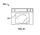
- FIG. 21is a top view of a track pad having a full pixel display, in accordance with one embodiment of the present invention.
- FIG. 22is side view, in cross section of electronic ink, in accordance with one embodiment of the present invention.
- FIG. 23is a side view of a piece of glass, in accordance with one embodiment of the present invention.
- FIG. 24Ais a side view of a piece of etched glass, in accordance with one embodiment of the present invention.
- FIG. 24Bis a top magnified view of the piece of glass shown in FIG. 24A .
- FIG. 25is a side view of a piece of etched glass, in accordance with one embodiment of the present invention.
- FIG. 26is a top view of the surface of the piece of glass shown in FIG. 25 .
- FIG. 27is a graph of the peak-to-peak ratio of the glass surface shown in FIGS. 25 and 26 .
- FIG. 28is a side view, in cross section of a portion of an input device, in accordance with one embodiment of the present invention.
- FIG. 29is a side view, in cross section of a portion of an input device, in accordance with one embodiment of the present invention.
- FIG. 30is a side view, in cross section of a portion of an input device, in accordance with one embodiment of the present invention.
- FIG. 31is a side view, in cross section of a portion of an input device, in accordance with one embodiment of the present invention.
- FIG. 32is a side view of an input device, in accordance with one embodiment of the present invention.
- FIG. 33is a bottom view of the input device of FIG. 32 .
- FIG. 34Ais a side view, in cross section, of an input device, in accordance with one embodiment of the present invention.
- FIG. 34Bis a side view, in cross section, of an input device, in accordance with one embodiment of the present invention.
- a Cartesian coordinate systemis used to monitor the position of the finger, mouse and ball, respectively, as they are moved.
- the Cartesian coordinate systemis generally defined as a two dimensional coordinate system (x, y) in which the coordinates of a point (e.g., position of finger, mouse or ball) are its distances from two intersecting, often perpendicular straight lines, the distance from each being measured along a straight line parallel to each other.
- x, y positions of the mouse, ball and fingermay be monitored.
- the x, y positionsare then used to correspondingly locate and move the input pointer on the display screen.
- Track padsgenerally include one or more sensors for detecting the proximity of the finger thereto.
- the sensorsmay be based on resistive sensing, surface acoustic wave sensing, pressure sensing, optical sensing, capacitive sensing and the like.
- the sensorsare generally dispersed about the track pad with each sensor representing an x, y position. In most cases, the sensors are arranged in a grid of columns and rows. Distinct x and y position signals, which control the x, y movement of a pointer device on the display screen, are thus generated when a finger is moved across the grid of sensors within the track pad.
- capacitive sensing technologiesFor brevity sake, the remaining discussion will be held to the discussion of capacitive sensing technologies. It should be noted, however, that the other technologies have similar features.
- Capacitive sensing surfacesgenerally contain several layers of material.
- the capacitive sensing surfacemay include a protective/cosmetic shield (usually a dielectric material), one or more electrode layers and a circuit board.
- the protective shieldtypically covers the electrode layer(s), and the electrode layer(s) is generally disposed on a front side of the circuit board.
- the electrode layer and circuit boardmay be, for example, a printed circuit board (PCB).
- the protective shieldis the part of the capacitive sensing surface that is touched by the user to implement cursor movements on a display screen.
- the electrode layer(s)on the other hand, is used to interpret the x, y position of the user's finger when the user's finger is resting or moving on the protective shield.
- the electrode layer (s)typically consists of a plurality of electrodes that are positioned in columns and rows so as to form a grid array.
- the columns and rowsare generally based on the Cartesian coordinate system and thus the rows and columns correspond to the x and y directions.
- the capacitive sensing surfacemay also include sensing electronics for detecting signals associated with the electrodes.
- the sensing electronicsmay be adapted to detect the change in capacitance at each of the electrodes as the finger passes over the grid.
- the sensing electronicsare generally located on the backside of the circuit board.
- the sensing electronicsmay include an application specific integrated circuit (ASIC) that is configured to measure the amount of capacitance in each of the electrodes and to compute the position of finger movement based on the capacitance in each of the electrodes.
- ASICapplication specific integrated circuit
- the ASICmay also be configured to report this information to the computing device.
- the track padis generally a small (often rectangular) area that includes a protective/cosmetic shield 12 and a plurality of electrodes 14 disposed underneath the protective shield 12 .
- Electrodes 14may be located on a circuit board, for example a printed circuit board (PCB).
- PCBprinted circuit board
- a portion of the protective shield 12has been removed to show the electrodes 14 .
- Each of the electrodes 14represents a different x, y position. In one configuration, as a finger 16 (or alternately a stylus, not shown) approaches the electrode grid 14 , a tiny capacitance forms between the finger 16 and the electrodes 14 proximate the finger 16 .
- the circuit board/sensing electronicsmeasures capacitance and produces an x, y input signal 18 corresponding to the active electrodes 14 which is sent to a host device 20 (e.g., a computing device) having a display screen 22 .
- the x, y input signal 18is used to control the movement of a cursor 24 on a display screen 22 .
- the input pointermoves in a similar x, y direction as the detected x, y finger motion.
- FIG. 2is a simplified perspective view of an input device 30 , in accordance with one embodiment of the present invention.
- the input device 30is generally configured to send information or data to an electronic device (not shown) in order to perform an action on a display screen (e.g., via a graphical user interface (GUI)). For example, moving an input pointer, making a selection, providing instructions, etc.
- GUIgraphical user interface
- the input devicemay interact with the electronic device through a wired (e.g., cable/connector) or wireless connection (e.g., IR, bluetooth, etc.).
- the input device 30may be a stand alone unit or it may be integrated into the electronic device. When in a stand alone unit, the input device typically has its own enclosure. When integrated with an electronic device, the input device typically uses the enclosure of the electronic device. In either case, the input device may be structurally coupled to the enclosure as for example through screws, snaps, retainers, adhesives and the like. In some cases, the input device may be removably coupled to the electronic device as for example through a docking station.
- the electronic device to which the input device is coupledmay correspond to any consumer related electronic product. By way of example, the electronic device may correspond to a computer such as a desktop computer, laptop computer or PDA, a media player such as a music player, a communication device such as a cellular phone, another input device such as a keyboard, and the like.
- the input device 30includes a frame 32 (or support structure) and a track pad 34 .
- the frame 32provides a structure for supporting the components of the input device.
- the frame 32in the form of a housing may also enclose or contain the components of the input device.
- the components, which include the track pad 34may correspond to electrical, optical and/or mechanical components for operating the input device 30 .
- Track pad 34provides an intuitive interface configured to provide one or more control functions for controlling various applications associated with the electronic device to which it is attached.
- the touch initiated control functionmay be used to move an object or perform an action on the display screen or to make selections or issue commands associated with operating the electronic device.
- the track pad 34may be arranged to receive input from a finger (or object) moving across the surface of the track pad 34 (e.g., linearly, radially, angular, etc.), from a finger holding a particular position on the track pad 34 and/or by a finger tapping on a particular position of the track pad 34 .
- the touch pad 34provides easy one-handed operation, i.e., lets a user interact with the electronic device with one or more fingers.
- the track pad 34may be widely varied.
- the touch pad 34may be a conventional track pad based on the Cartesian coordinate system, or the track pad 34 may be a touch pad based on a polar coordinate system.
- An example of a touch pad based on polar coordinatesmay be found in U.S. Pat. No. 7,046,230 to Zadesky et al., entitled “TOUCH PAD FOR HANDHELD DEVICE”, filed Jul. 1, 2002, which is herein incorporated in its entirety by reference thereto.
- the track pad 34may be used in a relative or absolute mode.
- absolute modethe track pad 34 reports the absolute coordinates of where it is being touched. For example x, y in the case of the Cartesian coordinate system or (r, ⁇ ) in the case of the polar coordinate system.
- relative modethe track pad 34 reports the direction and/or distance of change. For example, left/right, up/down, and the like.
- the signals produced by the track pad 34direct motion on the display screen in a direction similar to the direction of the finger as it is moved across the surface of the track pad 34 .
- the shape of the track pad 34may be widely varied.
- the track pad 34may be circular, oval, square, rectangular, triangular, and the like.
- the outer perimeter of the track pad 34defines the working boundary of the track pad 34 .
- the track padis rectangular. Rectangular track pads are common on laptop computers.
- the track pad 34which generally takes the form of a rigid planar platform, includes a touchable outer track surface 36 for receiving a finger (or object) for manipulation of the track pad.
- a sensor arrangementthat is sensitive to such things as the pressure and/or motion of a finger thereon.
- the sensor arrangementtypically includes a plurality of sensors that are configured to activate as the finger sits on, taps on or passes over them. In the simplest case, an electrical signal is produced each time the finger is positioned over a sensor.
- the number of signals in a given time framemay indicate location, direction, speed, and acceleration of the finger on the track pad 34 , i.e., the more signals, the more the user moved his finger.
- the signalsare monitored by an electronic interface that converts the number, combination and frequency of the signals into location, direction, speed and acceleration information. This information may then be used by the electronic device to perform the desired control function on the display screen.
- the sensor arrangementmay be widely varied.
- the sensorsmay be based on resistive sensing, surface acoustic wave sensing, pressure sensing (e.g., strain gauge), infra red sensing, optical sensing, dispersive signal technology, acoustic pulse recognition, capacitive sensing and the like.
- the track pad 34is based on capacitive sensing.
- a capacitively-based track padis arranged to detect changes in capacitance as the user moves an object such as a finger around the track pad.
- the capacitive track padincludes a protective shield, one or more electrode layers, a circuit board and associated electronics including an application specific integrated circuit (ASIC).
- the protective shieldis placed over the electrodes; the electrodes are mounted on the top surface of the circuit board; and the ASIC is mounted on the bottom surface of the circuit board.
- the protective shieldserves to protect the underlayers and to provide a surface for allowing a finger to slide thereon. The surface is generally smooth so that the finger does not stick to it when moved.
- the protective shieldalso provides an insulating layer between the finger and the electrode layers.
- the electrode layerincludes a plurality of spatially distinct electrodes. Any suitable number of electrodes may be used. In most cases, it would be desirable to increase the number of electrodes so as to provide higher resolution, i.e., more information can be used for things such as acceleration.
- Capacitive sensingworks according to the principals of capacitance. As should be appreciated, whenever two electrically conductive members come close to one another without actually touching, their electric fields interact to form capacitance.
- the first electrically conductive memberis one or more of the electrodes and the second electrically conductive member is, for example, the finger of the user. Accordingly, as the finger approaches the touch pad, a tiny capacitance forms between the finger and the electrodes in close proximity to the finger.
- the capacitance in each of the electrodesis measured by an ASIC located on the bottom (or backside) of the circuit board. By detecting changes in capacitance at each of the electrodes, the ASIC can determine the location, direction, speed and acceleration of the finger as it is moved across the touch pad. The ASIC can also report this information in a form that can be used by the electronic device.
- track pad 34is movable relative to frame 32 so as to initiate another set of signals (other than just tracking signals).
- track pad 34 in the form of the rigid planar platformmay rotate, pivot, slide, translate, flex and/or the like relative to frame 32 .
- Track pad 34may be coupled to frame 32 and/or it may be movably restrained by frame 32 .
- track pad 34may be coupled to frame 32 through screws, axels, pin joints, slider joints, ball and socket joints, flexure joints, magnets, cushions and/or the like.
- Track pad 34may also float within a space of the frame (e.g., gimbal).
- the input device 30may additionally include a combination of joints such as a pivot/translating joint, pivot/flexure joint, pivot/ball and socket joint, translating/flexure joint, and the like to increase the range of motion (e.g., increase the degree of freedom).
- touch pad 34When moved, touch pad 34 is configured to actuate a circuit that generates one or more signals.
- the circuitgenerally includes one or more movement indicators such as switches, sensors, encoders, and the like.
- An example of a gimbaled track padmay be found in patent application Ser. No. 10/643,256, entitled, “MOVABLE TOUCH PAD WITH ADDED FUNCTIONALITY,” filed Aug. 18, 2003, which is herein incorporated in its entirety by reference thereto.
- track pad 34takes the form of a depressible button that performs a “picking” action. That is, a portion of the entire track pad 34 acts like a single or multiple button such that one or more additional button functions may be implemented by pressing on track pad 34 rather than tapping on the track pad or using a separate button/separate zone.
- track pad 34is capable of moving between an upright (or neutral) position ( FIG. 3A ) and a depressed (or activate) position ( FIG. 3B ) when a force from a finger 38 , palm, hand, or other object is applied to the track pad 34 .
- Track pad 34is typically biased in the upright position as for example through a flexure hinge, a spring member, or magnets. Track pad 34 moves to the activate position when the bias is overcome by an object pressing on track pad 34 . As shown in FIG. 3C , the track pad 34 may be pivoted at one end such that the activate position is slightly inclined with respect to the neutral position. When the finger (or other object) is removed from track pad 34 , the biasing member urges it back towards the neutral position. A shim, shock absorber, upstop or other structure (not shown) may prevent track pad 34 from overshooting the neutral position as it returns.
- a portion of frame 32may extend outwardly above a portion of track pad 34 so as to stop track pad 34 at the neutral position. In this way, the track surface can be kept flush with frame 32 if desired. For example, in laptop computers or handheld media devices, it may be desirable to have the track pad flush with the housing of the computer or device.
- track pad 34in the upright/neutral position, track pad 34 generates tracking signals when an object such as a user's finger is moved over the top surface of the touch pad in the x,y plane.
- FIG. 3Adepicts the neutral position as being upright, the neutral position may be situated at any orientation.
- FIG. 3Bin the depressed position (z direction), track pad 34 generates one or more button signals.
- the button signalsmay be used for various functionalities including but not limited to making selections or issuing commands associated with operating an electronic device.
- the button functionsmay be associated with opening a menu, playing a song, fast forwarding a song, seeking through a menu and the like.
- the button functionscan be associated with opening a menu, selecting text, selecting an icon, and the like.
- input device 30may be arranged to provide both the tracking signals and the button signal at the same time, i.e., simultaneously depressing the touch pad 34 in the z direction while moving tangentially along the track surface (i.e. in the x, y directions). In other cases, input device 30 may be arranged to only provide a button signal when touch pad 34 is depressed and a tracking signal when the touch pad 34 is upright.
- track pad 34is configured to actuate one or more movement indicators, which are capable of generating the button signal when track pad 34 is moved to the activate position.
- the movement indicatorsare typically located within frame 32 and may be coupled to track pad 34 and/or frame 32 .
- the movement indicatorsmay be any combination of switches and sensors. Switches are generally configured to provide pulsed or binary data such as activate (on) or deactivate (off). By way of example, an underside portion of track pad 34 may be configured to contact or engage (and thus activate) a switch when the user presses on track pad 34 .
- the sensorsare generally configured to provide continuous or analog data.
- the senormay be configured to measure the position or the amount of tilt of touch pad 34 relative to the frame when a user presses on the track pad 34 .
- Any suitable mechanical, electrical and/or optical switch or sensormay be used.
- tact switches, force sensitive resistors, pressure sensors, proximity sensors and the likemay be used.
- Track pads 10 and 30 shown in FIGS. 1-3may, in some embodiments, be multi-touch trackpads.
- Multi-touchconsists of a touch surface (screen, table, wall, etc.) or touchpad, as well as software that recognizes multiple simultaneous touch points, as opposed to the standard touchscreen (e.g., computer touchpad, ATM), which recognizes only one touch point.
- This effectis achieved through a variety of means, including but not limited to: capacitive sensing, resistive sensing, surface acoustic wave sensing, heat, finger pressure, high capture rate cameras, infrared light, optic capture, tuned electromagnetic induction, and shadow capture.
- An example of a multi-touch mobile phoneis the iPhone produced by Apple Inc. of Cupertino, Calif.
- multi-touch media deviceAn example of a multi-touch media device is the iPod Touch produced by Apple Inc. Examples of laptop computers having multi-touch track pads are the MacBook Air and MacBook Pro produced by Apple Inc. All of the input devices described herein may employ multi-touch technology in some embodiments; alternatively the input devices described herein may employ single touch track pads.
- FIG. 4is a simplified block diagram of a computing system 39 , in accordance with one embodiment of the present invention.
- the computing systemgenerally includes an input device 40 operatively connected to a computing device 42 .
- the input device 40may generally correspond to the input device 30 shown in FIGS. 2 and 3
- the computing device 42may correspond to a laptop computer, desktop computer, PDA, media player, mobile phone, smart phone, video game or the like.
- input device 40includes a depressible track pad 44 and one or more movement indicators 46 .
- Track pad 44is configured to generate tracking signals and movement indicator 46 is configured to generate a button signal when the track pad 44 is depressed.
- track pad 44includes capacitance sensors 48 and a control system 50 for acquiring the position signals from sensors 48 and supplying the signals to computing device 42 .
- Control system 50may include an application specific integrated circuit (ASIC) that is configured to monitor the signals from sensors 48 , to compute the location (Cartesian or angular), direction, speed and acceleration of the monitored signals and to report this information to a processor of computing device 42 .
- Movement indicator 46may also be widely varied. In this embodiment, however, movement indicator 46 takes the form of a switch that generates a button signal when track pad 44 is depressed. Switch 46 may correspond to a mechanical, electrical or optical style switch. In one particular implementation, switch 46 is a mechanical style switch that includes a protruding actuator 52 that may be pushed by track pad 44 to generate the button signal. By way of example, the switch may be a tact switch or tactile dome.
- Both track pad 44 and switch 46are operatively coupled to computing device 42 through a communication interface 54 .
- the communication interfaceprovides a connection point for direct or indirect connection between the input device and the electronic device.
- Communication interface 54may be wired (wires, cables, connectors) or wireless (e.g., transmitter/receiver).
- Computing device 42generally includes a processor 55 (e.g., CPU or microprocessor) configured to execute instructions and to carry out operations associated with the computing device 42 .
- a processor 55e.g., CPU or microprocessor
- the processormay control the reception and manipulation of input and output data between components of the computing device 42 .
- processor 55executes instruction under the control of an operating system or other software.
- Processor 55can be a single-chip processor or can be implemented with multiple components.
- Computing device 42also includes an input/output (I/O) controller 56 that is operatively coupled to processor 54 .
- I/O controller 56may be integrated with processor 54 or it may be a separate component, as shown.
- I/O controller 56is generally configured to control interactions with one or more I/O devices that can be coupled to computing device 42 , for example, input device 40 .
- I/O controller 56generally operates by exchanging data between computing device 42 and I/O devices that desire to communicate with computing device 42 .
- Computing device 42also includes a display controller 58 that is operatively coupled to processor 54 .
- Display controller 58may be integrated with processor 54 or it may be a separate component, as shown.
- Display controller 58is configured to process display commands to produce text and graphics on a display screen 60 .
- display screen 60may be a monochrome display, color graphics adapter (CGA) display, enhanced graphics adapter (EGA) display, variable-graphics-array (VGA) display, super VGA display, liquid crystal display (LCD) (e.g., active matrix, passive matrix and the like), cathode ray tube (CRT), plasma displays, backlit light-emitting diode (LED) LCD displays, or the like.
- CGAcolor graphics adapter
- EGAenhanced graphics adapter
- VGAvariable-graphics-array
- LCDliquid crystal display
- CTRcathode ray tube
- LEDbacklit light-emitting diode
- track pad 44can comprise a glass surface functioning not only as a touch-sensitive surface, but also as a display screen; in this case display screen 60 shown in FIG. 4 would be integrated with the glass surface of the track pad 44 .
- An example of a media player having a touch sensitive displayis the iPod Touch produced by Apple Inc. of Cupertino Calif.
- An example of a mobile phone having a touch sensitive displayis the iPhone produced by Apple Inc. of Cupertino Calif.
- processor 54together with an operating system operates to execute computer code and produce and use data.
- the computer code and datamay reside within a program storage area 62 that is operatively coupled to processor 54 .
- Program storage area 62generally provides a place to hold data that is being used by computing device 42 .
- the program storage areamay include Read-Only Memory (ROM), Random-Access Memory (RAM), hard disk drive and/or the like.
- the computer code and datacould also reside on a removable program medium and loaded or installed onto the computing device when needed.
- program storage area 62is configured to store information for controlling how the tracking and button signals generated by input device 40 are used by computing device 42 .
- FIG. 5shows one embodiment of an input device, generally shown at 70 , comprising a track pad 72 connected to a frame 76 .
- Frame 76may be a housing for a stand alone input device, or it may be a casing for another device which incorporates track pad 72 , for example a laptop computer, desktop computer, hand held media device, PDA, mobile phone, smart phone, etc.
- Track pad 72includes various layers including an outer touch-sensitive track surface 74 for tracking finger movements. Track surface 74 may also provide a low friction cosmetic surface.
- track pad 72is based on capacitive sensing; therefore, it includes an electrode layer 80 , which, for example, may be implemented on a PCB. In the case of capacitive sensing, track surface 74 is a dielectric material.
- a stiffener 84is located below electrode layer 80 .
- Stiffener 84is shown in FIG. 5 and FIG. 6 , but in some embodiments may be omitted. Stiffener 84 may be used to compensate for the inherent flexibility of electrode layer 80 .
- Electrode layer 80responds to finger movements along track surface 74 by sending signals to sensor 82 . In the case of capacitive sensing, electrode layer 80 registers changes in capacitance based on finger movements and sensor 82 is a capacitive sensor. In this way, track pad 72 incorporates a touch sensor arrangement.
- Sensor 82is shown disposed on the bottom of electrode layer 80 , but it may be located elsewhere in other embodiments. If, as in the illustrated embodiment, sensor 82 is located on a movable part of track pad 72 , the input device may incorporate a flexible electrical connection (not shown) capable of moving with the system.
- a movement indicator 78is disposed on the bottom of track pad 72 .
- Movement indicator 78may be widely varied, however, in this embodiment it takes the form of a mechanical switch, which is typically disposed between the track pad 72 and the frame 76 .
- movement indicator 78may be a sensor, for example an electrical sensor.
- Movement indicator 78may be attached to frame 76 or to track pad 72 .
- movement indicator 78is attached to the bottom side of electrode layer 80 .
- movement indicator 78may tack the form of a tact switch and more particularly, may be an SMT dome switch (dome switch packaged for SMT).
- Track pad 72is shown in its neutral position in FIG. 5 , where movement sensor 78 is not in contact with frame 76 .
- track pad 72may move downward causing movement sensor 78 to register this change in position.
- movement sensor 78(a tact switch) would contact either frame 76 , or in this case set screw 88 .
- Set screw 88may be manually adjusted to alter the distance between the neutral and activate positions. In one embodiment (not shown), set screw 88 may directly abut movement sensor 78 in the neutral position, such that there is no slack or pre-travel in the system.
- a flexure hinge 86connects track pad 72 with frame 76 .
- Flexure hinge 86is a resilient material that flexes when a force is applied, but exerts a restoring force so as to urge track pad 72 back towards the neutral position.
- flexure hinge 86may be thin spring steel.
- flexure hinge 86will flex when a user pushes down on track surface 74 . Flexure 86 also urges track pad 72 towards its neutral position, which in the illustrated embodiment shown in FIG. 5 is horizontal. In this way, a user can press down virtually anywhere on track surface 74 and cause a “pick,” meaning that movement indicator 78 will register this depression. This is in contrast to prior track pads which incorporate separate track zones and pick zones. Being able to pick anywhere on track surface 74 will provide the user with a more intuitive and pleasurable interface. For example, a user may be able to generate tracking and button signals with a single finger without ever having to remove the finger from track surface 74 . In contrast, a user operating a track pad with separate track and pick zones may, for example, use a right hand for tracking and a left hand for picking, or a forefinger for tracking and a thumb for picking.
- a shoulder 90which may be an extension of frame 76 or a discreet member, blocks track pad 72 from traveling past its neutral position by contacting a part of track pad 72 , for example stiffener 84 . In this way, track surface 74 may be kept substantially flush with a top surface of frame 76 .
- the pick generated by pressing on track surface 74may include selecting an item on the screen, opening a file or document, executing instructions, starting a program, viewing a menu, and/or the like.
- the button functionsmay also include functions that make it easier to navigate through the electronic system, as for example, zoom, scroll, open different menus, home the input pointer, perform keyboard related actions such as enter, delete, insert, page up/down, and the like.
- Flexure hinge 86allows for a movable track pad in the minimum vertical space possible. Minimum vertical space is achieved because flexure hinge 86 is thin and is generally situated parallel to a bottom layer of track pad 72 , consequently, flexure hinge 86 does not appreciably add to the thickness of track pad 72 . Therefore, this arrangement is feasible for use in ultrathin laptop computers (or other ultrathin devices). In such ultrathin laptop computer applications, vertical space is extremely limited. In the past, the size of electrical components was often the limiting feature as to how small electrical devices could be made. Today, electrical components are increasingly miniaturized, meaning that mechanical components (e.g., movable track pads) may now be the critical size-limiting components.
- linear-actuatione.g., supporting a movable track pad by coil springs or the like
- springsmay add unnecessary complexity (increased part count, higher cost, higher failure rates, etc. . . . ) to the manufacturing process.
- Another disadvantage of springsis that in some embodiments springs may mask or compromise the tactile switch force profile.
- flexure 86can deliver a substantially consistent feel across track surface 74 , and give the user a more faithful representation of the tactile switch force profile.
- track pad 72pivots downwardly and activates switch 78 disposed underneath.
- switch 78When activated, switch 78 generates button signals that may be used by an electronic device connected to input device 70 .
- Flexure 86can constrain track pad 72 to move substantially about only one axis. This can be accomplished by, for example, using multiple flexures arranged along an axis on one side of track pad 72 , such as the rear side.
- track pad 72is made stiff (for example, by inclusion of stiffener 84 if necessary), a leveling architecture is achieved. The coupling of a stiff track pad 72 to flexure hinge 86 allows track pad 72 to remain level when articulated off-center.
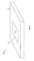
- FIG. 7 and FIG. 8show an input device 100 , in accordance with one embodiment of the present invention.
- FIG. 7is a perspective view of an input device 100 shown in use with a laptop computer.
- FIG. 8is an exploded perspective view of a disassembled track pad 101 used in input device 100 .
- Input deviceshown generally at 100 in FIG. 7 is a depressible touch-sensitive track pad 101 disposed in a laptop computer frame 104 .
- track surface 102As installed in computer frame 104 , the only portion of input device 100 visible to the user is track surface 102 , which may be flush with computer frame 104 .
- track surface 102is glass. Glass provides a dielectric, low-friction, durable, cosmetic surface.
- track surface 102is made of slightly frosted glass. In other embodiments, track surface 102 may be ceramic, plastic, or the like. If input device 100 is based on capacitive sensing, track surface 102 must be a dielectric material.
- the front end (i.e., nearest the user) of track surface 102has a mid point 201 and a corner 203 .
- Track surface 102moves approximately 0.2 mm when picked at the mid point of the extreme front end 201 . Due to the leveling architecture and stiffness of the illustrated embodiment, track surface 102 moves only approximately 0.4 mm when picked in the extreme left or right corner of the front end 203 , making input device 100 suitable for use with ultrathin laptops or other ultrathin applications where a depressible track pad is desirable.
- ink 106is for cosmetic purposes, and may be color-matched to the color of computer frame 104 . Alternatively, ink 106 may be a different color than computer frame 104 , for example, a different shade of a similar color or a contrasting color.
- a layer of pressure-sensitive adhesive (PSA) 108attaches glass 102 to the top surface of PCB 110 .
- a second layer of PSA 112attaches the bottom surface of PCB 110 to the top surface of stiffener 114 .
- PSA layers 110 and 112are shown as sheets shaped to match with the adjacent layers 106 , 110 , and 114 . Modifications can be made, for example cutting holes in layers 110 and 112 to accommodate rigid posts or epoxy glue or the like in order to control shear between adjacent layers. Alternatively, PSA layers 110 and 112 can be cut back at their perimeters in order to make room for an entire perimeter of glue. These modifications may strengthen the bond between adjacent layers when subjected to high shear loads. PSA is described herein by way of example; other means of attaching layers could be used, for example, double-sided tape, glue, or cement.
- PCBsgenerally have some inherent flex to them, which stiffener 114 substantially corrects for in order to add rigidity to track pad 101 .
- Stiffener 114may have cutouts 116 a to selectively reduce its weight, and or to selectively adjust its stiffness.
- Other cutouts, for example 118 anot only serve to reduce weight (or to modulate stiffness) but also to allow electrical contact between PCB 110 and sensors incorporated on flex 120 , as will be discussed below.
- Overlying PSA layer 112has corresponding cutouts 116 b and 118 b.
- stiffener 114should be stiff, light (i.e., low density), and thin enough for use in space-sensitive applications (e.g., ultrathin laptops, media devices, mobile phones, smart phones or the like).
- An ideal stiffenerwould be very stiff, very light, while at the same time very stiff.
- these three qualitiescan be considered as tradeoffs; for example, there is generally a tradeoff between stiffness and weight for a given material.
- stiffener 114is made of steel. Steel is a compromise material because it is moderately heavy, but is very stiff. Because of its high stiffness, a stiffener 114 constructed of steel can be made relatively thin. Other metals may be used, for example, aluminum or titanium. Titanium is very light but may be more expensive than steel.
- clad stiffenersmay be used, in particular clad metallic stiffeners formed from various metals or other materials.
- An exemplary clad metallic stiffener 115is shown in FIG. 9 consisting of, for example, an aluminum core 117 surrounded by an upper steel layer 119 and a lower steel layer 121 .
- Steelhas a higher elastic modulus (also known as modulus of elasticity) than inner core 117 of aluminum.
- An elastic modulusis the mathematical description of an object or substance's tendency to be deformed elastically (i.e., non-permanently) when a force is applied to it.
- a material with a higher elastic moduluse.g., steel
- a lower elastic moduluse.g. aluminum
- stiffener 115which has an aluminum core and steel outer layers, would be lighter but would not be as stiff.
- the clad effect(i.e., increasing stiffness by using high modulus materials as outer layers on a lightweight core) is similar to what happens with I-beams in constructing buildings; but in I-beams the second moment of area is adjusted instead of the elastic modulus. This is why beams with higher area moments of inertia, such as I-beams, are so often seen in building construction as opposed to other beams with the same area.
- stiffenerscan be made of any suitable structural material, including but not limited to glass, ceramics, tungsten carbide, carbon fiber composites, and metal matrix composites. Such structural materials are very light and thin, making them desirable for use as stiffeners in thin, lightweight portable electronic devices.
- PCB 110includes an electrode layer (not shown) on the top surface and a movement sensor 126 on the bottom surface.
- movement sensor 126is a mechanical switch (see FIGS. 8 and 11 ). Movement sensor 126 may be widely varied. Generally, tact switches may be used. More particularly, it may be a bare, packaged or encased metal dome switch.
- flexure hinge 122allows for displacement of track pad 101 , thereby allowing movement sensor 126 to contact set screw 128 . Since switch 126 is electrically connected to other parts of the system (e.g., it is mounted on PCB 110 ), a pick signal will be registered and processed each time the user presses down sufficiently far to actuate sensor 126 .
- Set screw 128can be adjusted to increase or completely eliminate any offset displacement from movement sensor 126 in the neutral position. As shown in FIG. 11 , there may be a small offset between movement sensor 126 and set screw 128 in the neutral position. In another embodiment (not shown), set screw 128 may directly abut switch 126 in the neutral position.
- Flexure 122will now be discussed with reference to FIGS. 8 , 10 , and 12 .
- two flexures 122are attached along a side of track pad 101 opposite sensor 126 .
- This arrangementconstrains track pad 101 to move generally as a pivot about an axis defined by the location of the flexures 122 .
- the physical separation of the flexures 122help to establish a leveling architecture.
- some amount of twist about a perpendicular axise.g., an axis on the midline of the track surface and perpendicular to the axis defined by the location of flexures 122 ) will also be possible if a user presses down on track surface 102 off center.
- This twistis partly from inherent flexibility in track pad 101 (even if stiffener 114 is used) and partly from variable bending of flexures 122 .
- This twistcould be at least partially compensated by, for example, a more robust stiffener and/or using more or stiffer flexures.
- track surface 102moves approximately 0.4 mm when pressed off center (e.g., at corner 203 in FIG. 7 ) and only approximately 0.2 mm when pressed on its centerline (e.g., at 201 in FIG. 7 ). This extremely small amount of twist does not degrade the performance of track pad 101 .
- Flexure 122has a top flexure portion 130 and a bottom flexure stiffener portion 132 .
- Flexure portion 130may be made of a thin resilient material, for example thin spring steel.
- flexure members 130When a flexible component is subject to bending stress, an instability can occur that manifests itself as a buckling. To relieve this instability, flexure members 130 have slots 134 , generally oriented substantially parallel to the axis about which they are most likely to be bent.
- Flexure stiffeners 132stiffen flexures 122 in the area where they are attached to frame 104 .
- each flexure 122has three fasteners 136 which thread through holes 136 a in flexure member 130 and holes 136 b in stiffener 114 .
- each flexure 122also has two more rear fasteners 138 which thread through holes 138 a in flexure 122 and 138 b in frame 104 to secure flexures 122 to frame 104 . While three fasteners 136 and two rear fasteners 138 are shown, the type and number of fasteners can be varied.
- two upstops 140are positioned above extensions 146 of stiffener 114 and below an extension or shoulder of frame 104 .
- This arrangementprevents track pad 101 from overshooting the neutral position after a depression cycle, maintaining track surface 102 substantially flush with a surface of frame 104 .
- PSA 144can be used to attach upstop 140 to frame 104 .
- PSA 144can be used to attach upstop 140 to stiffener 114 .
- flexures 122urge track pad 101 back towards the neutral position.
- extensions 146 of stiffener 114come into contact with upstop 140 , which is positioned underneath frame 104 .
- Upstop 140acts as a mild shock absorber, preventing stiffener 114 from actually contacting frame 104 , which may be substantially rigid. Suitable materials for upstop 140 include plastic, foam, rubber, biaxially-oriented polyethylene terephthalate (boPET) polyester film, which is known by the trade mark Mylar®, and the like. By absorbing the impact between stiffener 114 and frame 104 when the track pad 101 rebounds to neutral, Upstop 140 can selectively dampen undesirable acoustic noise after a depression cycle. Upstop 140 serves the dual function of shock absorption and limiting an upper range of motion of track pad 101 to coincide with the neutral position, which may be substantially flush with frame 104 . While two upstops 140 are shown, more or fewer may be used.
- Flex 120can best be seen in FIGS. 8 and 14 . Since track pad 101 is movable, flex 120 must be able to travel with track pad 101 as it moves. This is accomplished by providing a flexible electrical connection 150 , which runs between a computer connection 152 configured to communicate with the electronic device in which input device 100 is housed in, for example a laptop computer, and a sensor connection 154 configured to communicate with PCB 110 . Integrated circuits 156 are located on the top surface of flex 120 . Integrated circuits 156 receive and process data from the electrode layer on PCB 110 to form the heart of a capacitive sensor, providing functions such as reading when a user's finger, for example, is in contact with track surface 102 , and for determining finger movement.
- a PCB-based sensoris discussed by way of example, and not by way of limitation.
- Non-PCB sensorssuch as stamped sheetmetal, flex circuits (e.g., polyimide), conductive ink printed on substrates, e.g., polyethylene terephthalate (PET) substrates, indium tin oxide (ITO) on glass, and the like can also be used in the present invention.
- a cosmetic label 124covers flex 120 from below. The assembled input device 100 is seen from below in FIG. 10 .
- input device 100may be back lit.
- PCB 110can be populated with light emitting diodes (LEDs) on either side to enable a user to more easily see input device 100 in low light.
- LEDslight emitting diodes
- the input devices described hereinmay be integrated into an electronic device or they may be separate stand alone devices.
- FIG. 7shows an input device 200 integrated into a media player 202 while FIG. 16 shows an input device 207 integrated into a mobile phone.
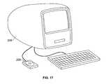
- FIGS. 17 and 18show some implementations of input device 200 as a stand alone unit.
- input device 200is a peripheral device that is connected to a desktop computer 206 .
- the input device 200is a remote control that wirelessly connects to a docking station 208 with a media player 210 docked therein.
- remote control 200can also be configured to interact with media player 210 (or other electronic device) directly thereby eliminating the need for a docking station.
- media player 210or other electronic device
- An example of a docking station for a media player with which the present invention may be usedcan be found in U.S. patent application Ser. No. 10/423,490, “MEDIA PLAYER SYSTEM,” filed Apr. 25, 2003, which is herein incorporated in its entirety by reference thereto. It should be noted that these particular embodiments are not a limitation and that many other devices and configurations may be used.
- the term “media player”generally refers to computing devices that are dedicated to processing media such as audio, video or other images, as for example, music players, game players, video players, video recorders, cameras, and the like.
- the media playerscontain single functionality (e.g., a media player dedicated to playing music) and in other cases the media players contain multiple functionality (e.g., a media player that plays music, displays video, stores pictures and the like).
- these devicesare generally portable so as to allow a user to listen to music, play games or video, record video or take pictures wherever the user travels.
- the media playeris a handheld device that is sized for placement into a pocket of the user.
- the userdoes not have to directly carry the device and therefore the device can be taken almost anywhere the user travels (e.g., the user is not limited by carrying a large, bulky and often heavy device, as in a laptop or notebook computer).
- a usermay use the device while working out at the gym.
- a usermay use the device while mountain climbing.
- the usercan use the device while traveling in a car.
- the devicemay be operated by the users hands, no reference surface such as a desktop is needed.
- the media player 202is a pocket sized hand held MP3 music player that allows a user to store a large collection of music (e.g., in some cases up to 40,000 CD-quality songs).
- the MP3 music playermay correspond to one of the iPod family of MP3 players manufactured by Apple Inc. of Cupertino, Calif.
- the MP3 music player shown hereinmay also include additional functionality such as storing a calendar and phone lists, storing and playing games, storing photos and the like. In fact, in some cases, it may act as a highly transportable storage device.
- the media player 202includes a housing 222 that encloses internally various electrical components (including integrated circuit chips and other circuitry) to provide computing operations for the media player 202 .
- the housing 222may also define the shape or form of the media player 202 . That is, the contour of the housing 222 may embody the outward physical appearance of the media player 202 .
- the integrated circuit chips and other circuitry contained within the housing 222may include a microprocessor (e.g., CPU), memory (e.g., ROM, RAM), a power supply (e.g., battery), a circuit board, a hard drive, other memory (e.g., flash) and/or various input/output (I/O) support circuitry.
- a microprocessore.g., CPU
- memorye.g., ROM, RAM
- a power supplye.g., battery
- I/Oinput/output
- the electrical componentsmay also include components for inputting or outputting music or sound such as a microphone, amplifier and a digital signal processor (DSP).
- the electrical componentsmay also include components for capturing images such as image sensors (e.g., charge coupled device (CCD) or complimentary oxide semiconductor (CMOS)) or optics (e.g., lenses, splitters, filters).
- image sensorse.g., charge coupled device (CCD) or complimentary oxide semiconductor (CMOS)
- CMOScomplimentary oxide semiconductor
- opticse.g., lenses, splitters, filters.
- the media player 202includes a hard drive thereby giving the media player massive storage capacity.
- a 160 GB hard drivecan store up to 40,000 songs, approximately 200 hours of video, or up to 25,000 photos.
- flash-based media playerson average store up to 128 MB, or about two hours, of music.
- the hard drive capacitymay be widely varied (e.g., 8, 16, 80, 160 GB, etc.).
- the media player 202 shown hereinalso includes a battery such as a rechargeable lithium ion battery. These type of batteries are capable of offering about 30 hours of continuous music playtime to the media player or 5 hours of video playtime.
- the media player 202also includes a display screen 224 and related circuitry.
- the display screen 224is used to display a graphical user interface as well as other information to the user e.g., text, objects, graphics).
- the display screen 224may be a liquid crystal display (LCD).
- the display screencorresponds to a 320-by-240-pixel high-resolution display LCD display, with LED backlight to give clear visibility in daylight as well as low-light conditions.
- the display screen 224is visible to a user of the media player 202 through an opening 225 in the housing 222 , and through a transparent wall 226 that is disposed in front of the opening 225 .
- the transparent wall 226may be considered part of the housing 222 since it helps to define the shape or form of the media player 202 .
- the media player 202also includes the touch pad 200 such as any of those previously described.
- the touch pad 200generally consists of a touchable outer surface 231 for receiving a finger for manipulation on the touch pad 230 .
- touch pad 200is circular, but its shape can be widely varied, e.g., rectangular, square, etc.
- a sensor arrangementbeneath the touchable outer surface 231 is a sensor arrangement.
- the sensor arrangementincludes a plurality of sensors that are configured to activate as the finger sits on, taps on or passes over them. In the simplest case, an electrical signal is produced each time the finger is positioned over a sensor.
- the number of signals in a given time framemay indicate location, direction, speed and acceleration of the finger on the touch pad, i.e., the more signals, the more the user moved his or her finger.
- the signalsare monitored by an electronic interface that converts the number, combination and frequency of the signals into location, direction, speed and acceleration information. This information may then be used by the media player 202 to perform the desired control function on the display screen 224 . For example, a user may easily scroll through a list of songs by swirling the finger around the touch pad 200 .
- the touch padmay also include a movable button configured to provide one or more dedicated control functions for making selections or issuing commands associated with operating the media player 202 .
- the button functionsmay be associated with opening a menu, playing a song, fast forwarding a song, seeking through a menu, making selections and the like. In most cases, the button functions are implemented via a mechanical clicking action.
- the position of the touch pad 200 relative to the housing 222may be widely varied.
- the touch pad 200may be placed at any external surface (e.g., top, side, front, or back) of the housing 222 that is accessible to a user during manipulation of the media player 202 .
- the touch sensitive surface 231 of the touch pad 200is completely exposed to the user.
- the touch pad 200is located in a lower, front area of the housing 222 .
- the touch pad 230may be recessed below, level with, or extend above the surface of the housing 222 .
- the touch sensitive surface 231 of the touch pad 200is substantially flush with the external surface of the housing 222 .
- touch pad 200may also be widely varied. Although shown as circular, the touch pad may also be annular, rectangular, triangular, and the like.
- Media player 202may also include a hold switch 234 .
- the hold switch 234is configured to activate or deactivate the touch pad and/or buttons associated therewith. This is generally done to prevent unwanted commands by the touch pad and/or buttons, as for example, when the media player is stored inside a user's pocket.
- signals from the buttons and/or touch padare not sent or are disregarded by the media player.
- signals from the buttons and/or touch padare sent and therefore received and processed by the media player.
- the media player 202may also include one or more headphone jacks 236 and one or more data ports 238 .
- the headphone jack 236is capable of receiving a headphone connector associated with headphones configured for listening to sound being outputted by the media device 202 .
- the data port 238is capable of receiving a data connector/cable assembly configured for transmitting and receiving data to and from a host device such as a general purpose computer (e.g., desktop computer, portable computer).
- the data port 238may be used to upload or down load audio, video and other images to and from the media device 202 .
- the data portmay be used to download songs and play lists, audio books, ebooks, photos, and the like into the storage mechanism of the media player.
- the data port 238may be widely varied.
- the data portmay be a PS/2 port, a serial port, a parallel port, a USB port, a Firewire port and/or the like.
- the data port 238may be a radio frequency (RF) link or optical infrared (IR) link to eliminate the need for a cable.
- the media player 202may also include a power port that receives a power connector/cable assembly configured for delivering powering to the media player 202 .
- the data port 238may serve as both a data and power port.
- the data port 238is a Firewire port having both data and power capabilities.
- the data portmay include multiple data functionality, i.e., integrating the functionality of multiple data ports into a single data port.
- the position of the hold switch, headphone jack and data port on the housingmay be widely varied. That is, they are not limited to the positions shown in FIG. 15 . They may be positioned almost anywhere on the housing (e.g., front, back, sides, top, bottom), or even be absent in some embodiments.
- the data portmay be positioned on the bottom surface of the housing rather than the top surface as shown.
- Phone 207may be a smart phone.
- Mobile phone 207comprises a frame 209 and a touch sensitive screen 211 .
- Touch-sensitive screen 211which may be a multi-touch screen, similar to that used on the iPhone produced by Apple Inc. of Cupertino, Calif. can be made clickable by allowing it to displace relative to frame 209 when pressed on.
- a button functionalitylike the previously described depressible input devices of the present invention can be incorporated to phone 207 .
- tactile and/or aural feedbackmay be incorporated with the button function. For example, pressing down on screen 211 not only activates some function, but may also produce an audible clicking sound.
- the clicking soundmay be mechanically produced (for example by the mechanical switch itself) and/or may be electrically produced (for example through a speaker which is activated whenever the user presses down far enough).
- tactile feedbackcan be generated, for example the mechanical feedback generated by positively clicking a mechanical switch or a vibration which is triggered whenever a pick is detected.
- tactile and/or aural feedbackmay be incorporated with the button function of any embodiment discussed herein (e.g., laptop track pad, media player track pad or screen, remote control track pad, etc. . . . )
- a mobile phonecan incorporate a non-touch sensitive screen (i.e., a traditional screen) in conjunction with a touch-sensitive, depressible track pad, such as the track pads previously described herein.
- the screenfunctions as the display, while the track pad can, for example, move a cursor on the display and also incorporate a button function.
- a depressible track padcan be used on a mobile phone in conjunction with a separate screen instead of depressing the screen itself, as was the case with the embodiment discussed in reference to FIG. 16 .
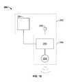
- FIG. 19a simplified block diagram of a remote control 280 incorporating an input device 282 therein, in accordance with another embodiment of the present invention is shown.
- input device 282may correspond to any of the previously described input devices of the present invention.
- Input device 282includes a touch pad 284 and switch 286 .
- Touch pad 284 and switch 286are operatively coupled to a wireless transmitter 288 , configured to transmit information over a wireless communication link so that an electronic device having receiving capabilities may receive the information over the wireless communication link.
- the wireless transmitter 288may be widely varied.
- the wireless transmitter 288is based on wireless technologies such as FM, RF, Bluetooth, 802.11 UWB (ultra wide band), infrared (IR), magnetic link (induction) and/or the like.
- the wireless transmitter 288is based on IR.
- IRgenerally refers wireless technologies that convey data through infrared radiation.
- the wireless transmitter 288generally includes an IR controller 290 .
- the IR controller 290takes the information reported from the touch pad 284 and switches 286 and converts this information into infrared radiation as for example using a light emitting diode 292 .
- the track surface of the present inventionmay be made of glass. Besides providing a low friction, durable, cosmetic surface, glass provides for options that opaque surfaces (e.g., plastic, ceramic, and the like) do not provide.
- track pad 101can be delineated into separate zones, using, for example, lights, textured glass, or combinations thereof. Each zone can have a different function. For example, one zone may be a track zone (which may move a cursor) while another zone may be a pick zone (which may be depressible to activate a button function.)
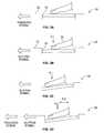
- FIGS. 20 a - 20 eshow exemplary delineation options for track pad 300 .
- FIG. 20 ashows transparent or semi-transparent track pad 300 made of glass with a single zone 302 , i.e., the entire track surface is depressible to activate a button function.
- FIG. 20 bshows track pad 300 with an upper track surface 304 and a single pick zone 306 .
- the line 308 which separates track surface 304 from pick zone 306can be created by a textured glass surface with LED side lighting, IR ink with LED side lighting, electro-luminescence, magnetic ink, two-tone rolling wire, or the like.
- FIG. 20 cshows an alternate embodiment having two pick zones 310 and 312 .
- FIG. 20 dshows two track zones that are left-biased, i.e., left pick zone 314 is larger than right pick zone 316 .
- FIG. 20 eshows two track zones that are right-biased, i.e. left pick zone 318 is smaller than right pick zone 320 .
- FIG. 20 fshows three pick zones 322 .
- the delineation options shown in FIG. 20are given by way of example, and not by way of limitation.
- track and pick zonescan be user-selectable.
- the usercan turn off the delineation line(s), such that the track pad is like that shown in FIG. 20 a corresponding to a track pad that can be picked anywhere on its track surface, which now functions similar to the embodiment shown in FIG. 7 .
- the user later desires a more traditional track pad having left and right pick zoneshe can configure the track pad to appear as shown in FIG. 20 c , with a corresponding change in functionality of the track pad.
- a track pad 324 with a glass (or otherwise transparent or semi-transparent) track surface 326can even function as a full pixel display.
- track surface 326can be an active matrix display, for example using electronic paper/electronic ink, LCD, thin film transistor liquid crystal display (TFT-LCD), etc.
- E ink®is the trade mark for one type of electronic paper developed by E Ink Corporation of Cambridge, Mass.
- the principal components of E ink®are millions of tiny microcapsules 327 , about the diameter of a human hair.
- each microcapsulecontains positively charged white particles 328 and negatively charged black particles 330 suspended in a clear fluid 332 .
- a negative electric field 334is applied, the white particles move to the top of the microcapsule to become visible to the reader. This makes the surface appear white at that spot.
- an opposite electric field 336pulls the black particles to the bottom of the microcapsules where they are hidden. By reversing this process, the black particles appear at the top of the capsule, which now makes the surface appear dark at that spot.
- the top 338 and/or bottom 340 electrodesare transparent so that a user can see the colored particles.
- E Ink® electronic displaythe ink is printed onto a sheet of plastic film that is laminated to a layer of circuitry.
- the circuitryforms a pattern of pixels that can then be controlled by a display driver.
- These microcapsulesare suspended in a liquid “carrier medium” allowing them to be printed using existing screen printing processes onto virtually any surface, including glass, plastic, fabric and even paper.
- An exemplary E ink® displaywas unveiled in February 2004 by Polymer Vision Ltd.
- This displayis an organics-based quarter VGA (QVGA) (i.e., 320 ⁇ 240 pixels) active matrix display with a diagonal of five inches, a resolution of 85 dpi and a bending radius of 2 cm.
- QVGAorganics-based quarter VGA
- the displaycombined a 25 micron thick active-matrix back pane containing the polymer electronics-based pixel driving, with a 200 micron front plane of reflective E Ink®.
- a glass surfacecan be used as a track surface in some embodiments of the present invention.
- a glass surfaceshould have a low coefficient of friction, should be clean with high clarity, should not readily pick up smudges, readily scratch, or be abrasive to skin, and finally should be mechanically robust in order to survive thousands of cycles of track pad depressions.
- conventional glass structuresdo not have all of these attributes simultaneously, e.g., conventional glass may be very clear, but it has a high coefficient of friction. Low friction is important in track pads (e.g., track pads on laptop computers) because overcoming excessive frictional forces between the glass and a user's finger, for example, can cause user discomfort or could cause inadvertent picks in the case of a depressible track pad.
- the preferred glass surfaceis one that is silky-smooth and highly optically clear.
- a finger rubbed across a piece of etched glasswill have to overcome frictional forces associated with directly contacting the bumps or peaks on the etched glass surface, but the finger will experience greatly reduced friction in areas between the bumps or peaks, which is essentially just air.
- Producing a final piece of treated glassis commonly been done in one step.
- the raw glassis chemically etched.
- this single-step methoddoes not yield a glass surface that has all of the desirable attributes mentioned above.
- the glass surfacemay have lower friction, but is often associated with decreased clarity or decreased smudge resistance.
- Efforts to process the glass in multiple stepse.g., mechanical abrasion followed by chemical post-processing has also not been previously successful; the glass surfaces produced in multiple steps suffer the same disadvantages as those produced in a single step.
- raw glassmay be processed in a two step method to produce a much improved glass.
- a piece of raw glass 342is processed mechanically or chemically to create a “seed surface” with a fine pitch. Tailoring the seed surface to have a very fine pitch (i.e., a very rough surface) would enable a subsequent liquid-polishing (i.e., in the second step) so as to produce a final glass surface having all of the desirable attributes.
- the seed surfaceis best seen in FIG. 24A where the processed glass has a bumpy surface 346 characterized by a peak-to-peak ratio 348 and an amplitude 350 . This is the seed surface.
- a fine pitch seed surface, such as 346will have a very low transmittance (ratio of transmitted to incident light), on the order of 30%.
- the first step of processing the glassmay be performed using chemical etching, for example using ammonium BiFlouride cream mixed with an inert carrier. This chemical etching cream is applied to the surface and left there for a period of time, for example 30 minutes.
- FIG. 24Bshows the seed surface 346 at the conclusion of the first step. The seed surface is shown at 1,000 magnification. The scale at the bottom of FIG. 24B is scaled to 10 ⁇ m.
- the seed surfaceis exposed to a hydrofluoric acid (HF) solution incorporating a secondary acid.
- HFhydrofluoric acid
- the solutionconsists of HF and hydrocholoric acid, i.e., HF+HCl.
- the solutionconsists of HF and sufluric acid, i.e., HF+H 2 SO 4 .
- the acid solutionmay be mixed with water. The higher the concentration of HF the faster the process will occur, but the net result will be the same.
- the solutionmay consist of approximately 5% HF with approximately 10% HCl and approximately 85% H 2 O.
- the primary acidis HF
- the secondary acidHCl or H 2 SO 4
- the HFreacts with seed surface 346 produced during the first step and changes its topography, which in turn changes the relevant properties of the glass (e.g., transmittance, coefficient of friction).
- the resulting final glass surface 356is shown in FIG. 25 .
- Surface 356has an amplitude 352 roughly equal to amplitude 350 of the seed surface, but a peak-to-peak ratio 354 that is roughly an order of magnitude larger (e.g., eight to twelve times) than the peak-to-peak ratio 348 of seed surface 346 .
- the amplitudeis not significantly correlated to the relevant glass properties; the peak-to-peak ratio is the dominant characteristic. In other words, varying the amplitude of the final glass surface did not affect the relevant glass properties, while independently varying the peak-to-peak ratio drastically affected the relevant properties.
- the final surface 356has a matrix of divots 358 , resembling a metal surface that has been randomly struck by a ball peen hammer.
- the resulting glasshas all of the desirable attributes (low friction, clear, durability, smudge-resistant, etc. . . . ), and has an appearance that is “lively” and “sparkly.”
- the transmittance of this glassis on the order of 90%.
- the final surface 356is a low friction surface.
- the coefficient of friction, ⁇ , of a surfaceis the ratio of a normal force, F N , from an object on that surface to the frictional force, F F , that must be overcome in order to move the object relative to the surface, i.e.,
- ⁇F N F f .
- the frictional forceis further classified into static and dynamic friction.
- Static friction, F Sis the force that must be overcome when two objects are not moving relative to each other
- dynamic friction, F Dis the frictional force between two objects in relative motion.
- Static frictionis typically higher than dynamic friction, i.e., it normally takes a larger force to get an object moving relative to another surface when they were initially stationary, but a smaller force to keep the object in motion.
- the coefficients of static ⁇ S and dynamic ⁇ D frictionare therefore defined as:
- neoprene disk with a roughened surface using 320-grit sandpaperwas loaded with a normal force and pulled along various samples of surfaces like 356 .
- Testswere performed on various samples, and the neoprene disk was either pulled at 50 mm/min or 500 mm/min, and was loaded at either 71.4 grams or 295.9 grams.
- the surfacewas lubricated with squalene during some tests and not lubricated during the other tests. Table 1 summarizes the testing data:
- FIG. 27shows the peak-to-peak ratio produced in the second step of the glass treatment process as a function of time.
- the peak-to-peak ratiorapidly increases before a critical time Tcrit 360 , at which point it proceeds basically asymptotically. This is important in manufacturing the glass because the process window of the second step is very large.
- the second step chemical treatment processis not time sensitive; the treatment can be applied and left on the glass for either a shorter time (near Tcrit 360 ) or for a much longer time to still get a relatively constant peak-to-peak ratio. This means that the time does not have to be carefully controlled; therefore, defective parts that would have needed to be scrapped if the peak-to-peak ratio were incorrect are reduced or eliminated.
- the peak-to-peak ratiostays substantially constant in the asymptotic part of the peak-to-peak curve, the overall thickness of the glass is constantly decreasing during this process because the HF thins the glass.
- the first stepcan employ a mechanical treatment in lieu of the chemical treatment described above.
- the glasscan be treated with a fine grit (e.g., cerium oxide) and then mechanically honed. In some cases though, this may create micro fractures and/or give the final glass a lower four-point bending strength.
- a chemical treatmentas described above, may be preferred to mechanical honing.
- the two-step process of the present inventioncan be performed on a large sheet of glass, which is then subsequently cut into the desired shape, such as a rectangle.
- the raw glasscan be cut into the desired shape first, and then treated. Cutting the glass into smaller shapes can introduce imperfections into the glass (e.g., small chips) which the chemical treatment can subsequently mask; therefore, in some embodiments it is desirable to cut the raw glass before treating it.
- PCB 110can serve as the flexure hinge in an alternate embodiment. This has the advantage of requiring fewer parts.
- track surface 102 and stiffener 114surround PCB 110 except for a cantilevered portion 105 attached to computer frame 104 .
- a gap 106is formed which serves as the flexure hinge.
- the track padWhen a user presses down on track surface 102 , the track pad will pivot about 106 as cantilevered PCB 110 flexes in the area of 106 .
- PCB 110will urge the track pad back to the neutral position, which in the illustrated embodiment is shown as horizontal.
- gap 106may be eliminated.
- FIG. 29shows another embodiment where a flexure hinge is made entirely from stiffener 114 .
- stiffener 114has a cantilevered end 107 that is thinner than the main body of stiffener 114 .
- End 107is attached to computer frame 104 in an opening 109 in frame 104 .
- the track padwill pivot as end 107 flexes along gap 106 .
- end 107 of stiffener 114will urge the track pad back to the neutral position, which in the illustrated embodiment is shown as horizontal.
- FIG. 30shows a flexure hinge made from a clad stiffener 123 .
- clad stiffener 123has, for example, and aluminum core 125 surrounded by an upper steel layer 127 and a lower steel layer 129 .
- upper layer 127has a cantilever extension 131 which is attached to computer frame 104 in an opening 109 in frame 104 .
- extension 131will urge the track pad back to the neutral position, which in the illustrated embodiment is shown as horizontal.
- core 125 or lower steel layer 129may have a cantilever extension (not shown) to connect to frame 104 and act as a flexure hinge.
- Materials other than aluminum and steelmay be used in a clad stiffener, provided they are stiff (i.e., high elastic modulus), thin, and are low density (i.e., lightweight).
- stiffener 133is unitary with computer frame 104 .
- the track padWhen a user presses down on track surface 102 , the track pad will pivot as stiffener 133 flexes.
- stiffener 133When pressure from the user is relieved, stiffener 133 will urge the track pad back to the neutral position, which in the illustrated embodiment is shown as horizontal.
- stiffener 133 and housingmay be made of aluminum, for example.
- FIGS. 32 and 33Another input device 135 according to the present invention is shown in FIGS. 32 and 33 .
- input device 135has a track surface 137 , an electrode (or PCB) layer 139 , and a stiffener 141 .
- Stiffener 141partially extends into a cavity 143 of computer frame 145 .
- a trap 147is attached to the underside of frame 145 .
- Trap 147has an X-Y alignment post 151 which extends into a notch 153 in stiffener 141 .
- X-Y alignment post 151fits inside of notch 153 and prevents stiffener 141 from moving in its own plane.
- Offset 155extends along the front edge or pivot edge 157 of trap 147 and an area 159 between notch 153 and the maximum thickness of stiffener 141 .
- stiffener 141rotates about pivot edge 157 .
- the presence of offset 155 and stiffener thickness transition 159enables one-way rotation downward of input device 135 .
- One-way rotationis desirable to retain input device 135 inside of frame 145 and to keep track surface 137 flush to the outside of frame 145 in the nominal state as represented in FIG. 32 .
- any of the flexure hinges described hereindo not appreciably add to the thickness of the depressible track pads. Therefore, any of the flexure hinges of the present invention are particularly suitable for use in ultrathin applications (laptops, media devices, mobile phones, game players, etc.)
- a mechanical dome switchserves as the primary restorative member to urge the track pads back to their neutral positions whenever the user is not depressing the track pad to activate the button function. Inherent flexibility in the various flexure hinges described above also urges the track pads back to their neutral positions.
- the mechanical domeis also responsible for providing tactile feedback to a user for a pick event. It is possible to use magnetic forces to bias a track pad to the neutral position and or to provide tactile feedback to the user. Magnetic force can be the sole biasing and tactile mechanism, or it can enhance existing biasing and tactile feel due to the mechanical dome switch and inherent flexibility from flexure hinges. In other words, magnets can be used on any of the previously discussed input devices to supplement the bias and tactile feel to the neutral position.
- Input device 161has a track pad 163 having a track surface 165 .
- track pad 163has a sensor arrangement to detect and process finger movements on track surface 165 .
- track pad 163may employ capacitive sensing.
- track pad 163has an electrode layer 167 (which may be on a PCB) for capacitive sensing.
- track pad 163has a pick zone 169 which is separated from track surface 165 .
- a usermoves his finger relative to track surface 165 in order to perform tracking operations (e.g., move a cursor) but depresses pick zone 169 in order to activate a button functionality.
- Input device 161is shown in the neutral position in FIG. 34 a .
- Magnetic attractive forces between magnet 179 and flange 177biases the pick zone 169 to the neutral position and allows for movement to an activate position (to activate a button function) whenever a user depresses pick zone 169 .
- Button assembly 171consists of a leveling plate 173 , flexure attachment 175 , flange 177 and pick zone 169 .
- Leveling plate 173is composed of a relatively stiff material, for example, steel, which is also optimally thin and lightweight.
- Leveling plate 173is connected to track pad 163 by flexure attachment 175 , which may be, for example, a thin piece of steel attached with screws.
- Flexure attachment 175is capable of bending, similar to flexure hinge 122 discussed in relation to FIGS. 8 , 10 , and 12 .
- flexure attachment 175can be a pivot pin assembly.
- button assembly 171hinges or pivots at flexure attachment 175 causing a movement sensor (not shown) to activate.
- the movement sensormay be capacitive, proximity, Hall-effect, optical, mechanical membrane or a plurality of sensors.
- Input device 161is shown in the activate position in FIG. 34 b.
- Magnet 179may be positioned anywhere, but in the illustrated embodiment, flange 177 is located on an end of leveling plate 173 and is situated directly below magnet 179 which is opposite the pivot point defined by flexure attachment 175 .
- Flange 177may be a ferrous metal or other material capable of being attracted magnetically.
- Magnet 179may be, for example, a permanent magnet, or electromagnet.
- magnet 179is fixedly connected to the housing (not shown) of input device 161 . In another embodiment, 179 may be fixed to the housing (not shown) of an electronic device in which input device 161 is incorporated.
- magnet 179would not move, but flange 177 would move with leveling plate 173 when the magnetic force attraction between magnet 179 and flange 177 is overcome by the user depressing pick zone 169 .
- the magnetmay move with leveling plate 173 while the metal portion stays fixed; in other words, magnet 179 and flange 177 can be the reverse of what is shown in FIG. 34 .
- flange 177may be a separate component from or it may integral with the housing (not shown).
- the magnetic force between magnet 179 and flange 177can be controlled to obtain the desired click feel, for example by using a stronger or weaker permanent magnet, by varying the size or separation of magnet 179 and or flange 177 , or by using an adjustable electromagnet.
- magnetic biasingcan be used on a track pad having a depressible track surface, such as those described above.
- magnetscan be used to bias depressible track pads to their neutral position.
- magnetscan be used with track pad 100 shown in FIG. 7 , or with the various flexure hinges shown in FIGS. 28-32 .
Landscapes
- Engineering & Computer Science (AREA)
- Theoretical Computer Science (AREA)
- General Engineering & Computer Science (AREA)
- Human Computer Interaction (AREA)
- Physics & Mathematics (AREA)
- General Physics & Mathematics (AREA)
- Computer Hardware Design (AREA)
- Position Input By Displaying (AREA)
Abstract
Description
The frictional force is further classified into static and dynamic friction. Static friction, FS, is the force that must be overcome when two objects are not moving relative to each other, while dynamic friction, FD, is the frictional force between two objects in relative motion. Static friction is typically higher than dynamic friction, i.e., it normally takes a larger force to get an object moving relative to another surface when they were initially stationary, but a smaller force to keep the object in motion. The coefficients of static μSand dynamic μDfriction are therefore defined as:
| TABLE 1 |
| Friction Data |
| FN | Test 1 | Test 2 | Test 3 | Standard | Standard | ||||
| Sample | (grams) | Lubrication | (grams) | (grams) | (grams) | μD | deviation | μS/μD | deviation |
| 1 | 71.4 | Yes | 32.37 | 33.27 | 32.41 | 0.46 | 0.01 | 1.07 | 0.01 |
| 1 | 295.9 | Yes | 106.46 | 105.85 | 111.39 | 0.36 | 0.01 | 1.04 | 0.01 |
| 1 | 71.4 | Yes | 38.58 | 37.35 | 39.07 | 0.54 | 0.01 | 1.16 | 0.06 |
| 1 | 295.9 | Yes | 115.5 | 115.63 | 116.35 | 0.39 | 0.00 | 1.08 | 0.03 |
| 1 | 71.4 | No | 77.77 | 78.17 | 76.58 | 1.09 | 0.01 | 1.03 | 0.00 |
| 1 | 295.9 | No | 284.24 | 268.88 | 260.79 | 0.92 | 0.04 | ||
| 1 | 71.4 | No | 58.9 | 58.68 | 56.4 | 0.81 | 0.02 | 1.31 | 0.04 |
| 1 | 295.9 | No | 250.52 | 246.24 | 244.39 | 0.83 | 0.01 | 1.09 | 0.05 |
| 2 | 71.4 | Yes | 25.3 | 24.65 | 25.25 | 0.35 | 0.01 | 1.13 | 0.08 |
| 2 | 295.9 | Yes | 81.75 | 81.83 | 83.2 | 0.28 | 0.00 | 1.10 | 0.02 |
| 2 | 71.4 | Yes | 40.35 | 37.02 | 35.47 | 0.53 | 0.03 | 1.15 | 0.02 |
| 2 | 295.9 | Yes | 111.77 | 112.91 | 110.12 | 0.38 | 0.00 | 1.05 | 0.01 |
| 2 | 71.4 | No | 94.67 | 92.67 | 87.71 | 1.28 | 0.05 | 1.05 | 0.02 |
| 2 | 295.9 | No | n/a | n/a | n/a | n/a | n/a | n/a | n/a |
| 2 | 71.4 | No | 81.52 | 81.89 | 80.82 | 1.14 | 0.01 | 1.21 | 0.04 |
| 2 | 295.9 | No | 341.19 | 332.56 | 324.6 | 1.12 | 0.03 | 1.06 | 0.01 |
| 3 | 71.4 | Yes | 24 | 24.58 | 25.08 | 0.34 | 0.01 | 1.07 | 0.02 |
| 3 | 295.9 | Yes | 78.22 | 78.63 | 78.78 | 0.27 | 0.00 | 1.04 | 0.02 |
| 3 | 71.4 | Yes | 33.49 | 34.48 | 36.04 | 0.49 | 0.02 | 1.10 | 0.01 |
| 3 | 295.9 | Yes | 102.95 | 102.49 | 103.29 | 0.35 | 0.00 | 1.03 | 0.00 |
| 3 | 71.4 | No | 82.32 | 90.8 | 85.67 | 1.21 | 0.06 | 1.18 | 0.09 |
| 3 | 295.9 | No | n/a | n/a | n/a | n/a | n/a | n/a | n/a |
| 3 | 71.4 | No | 101 | 98.1 | 96.93 | 1.38 | 0.03 | 1.10 | 0.01 |
| 3 | 295.9 | No | 371.08 | 368.13 | 365.01 | 1.24 | 0.01 | 1.01 | 0.00 |
Claims (25)
Priority Applications (9)
| Application Number | Priority Date | Filing Date | Title |
|---|---|---|---|
| US12/241,967US8441450B2 (en) | 2008-09-30 | 2008-09-30 | Movable track pad with added functionality |
| CN200980138687.2ACN102171632B (en) | 2008-09-30 | 2009-09-01 | There is the movable tracking plate of greater functionality |
| EP09792130.8AEP2329343B1 (en) | 2008-09-30 | 2009-09-01 | Movable track pad with added functionality |
| KR1020117009934AKR101258008B1 (en) | 2008-09-30 | 2009-09-01 | Movable track pad with added functionality |
| JP2011529063AJP5308531B2 (en) | 2008-09-30 | 2009-09-01 | Movable trackpad with additional functionality |
| PCT/US2009/055591WO2010039383A2 (en) | 2008-09-30 | 2009-09-01 | Movable track pad with added functionality |
| US13/864,193US20130285984A1 (en) | 2008-09-30 | 2013-04-16 | Movable track pad with added functionality |
| US14/660,800US9612674B2 (en) | 2008-09-30 | 2015-03-17 | Movable track pad with added functionality |
| US15/477,409US20170285781A1 (en) | 2008-09-30 | 2017-04-03 | Movable Track Pad with Smudge-Resistant Input Surface |
Applications Claiming Priority (1)
| Application Number | Priority Date | Filing Date | Title |
|---|---|---|---|
| US12/241,967US8441450B2 (en) | 2008-09-30 | 2008-09-30 | Movable track pad with added functionality |
Related Child Applications (1)
| Application Number | Title | Priority Date | Filing Date |
|---|---|---|---|
| US13/864,193ContinuationUS20130285984A1 (en) | 2008-09-30 | 2013-04-16 | Movable track pad with added functionality |
Publications (2)
| Publication Number | Publication Date |
|---|---|
| US20100079404A1 US20100079404A1 (en) | 2010-04-01 |
| US8441450B2true US8441450B2 (en) | 2013-05-14 |
Family
ID=42056883
Family Applications (4)
| Application Number | Title | Priority Date | Filing Date |
|---|---|---|---|
| US12/241,967Expired - Fee RelatedUS8441450B2 (en) | 2008-09-30 | 2008-09-30 | Movable track pad with added functionality |
| US13/864,193AbandonedUS20130285984A1 (en) | 2008-09-30 | 2013-04-16 | Movable track pad with added functionality |
| US14/660,800ActiveUS9612674B2 (en) | 2008-09-30 | 2015-03-17 | Movable track pad with added functionality |
| US15/477,409AbandonedUS20170285781A1 (en) | 2008-09-30 | 2017-04-03 | Movable Track Pad with Smudge-Resistant Input Surface |
Family Applications After (3)
| Application Number | Title | Priority Date | Filing Date |
|---|---|---|---|
| US13/864,193AbandonedUS20130285984A1 (en) | 2008-09-30 | 2013-04-16 | Movable track pad with added functionality |
| US14/660,800ActiveUS9612674B2 (en) | 2008-09-30 | 2015-03-17 | Movable track pad with added functionality |
| US15/477,409AbandonedUS20170285781A1 (en) | 2008-09-30 | 2017-04-03 | Movable Track Pad with Smudge-Resistant Input Surface |
Country Status (6)
| Country | Link |
|---|---|
| US (4) | US8441450B2 (en) |
| EP (1) | EP2329343B1 (en) |
| JP (1) | JP5308531B2 (en) |
| KR (1) | KR101258008B1 (en) |
| CN (1) | CN102171632B (en) |
| WO (1) | WO2010039383A2 (en) |
Cited By (52)
| Publication number | Priority date | Publication date | Assignee | Title |
|---|---|---|---|---|
| US20120310572A1 (en)* | 2009-09-08 | 2012-12-06 | Synaptics Incorporated | Sensing and defining an input object |
| US20130002571A1 (en)* | 2011-01-03 | 2013-01-03 | Peter James Skinner | Devices and processes for data input |
| US20140071050A1 (en)* | 2012-09-13 | 2014-03-13 | Apple Inc. | Optical Sensing Mechanisms for Input Devices |
| US20140211396A1 (en)* | 2013-01-29 | 2014-07-31 | Kabushiki Kaisha Toshiba | Electronic apparatus |
| WO2014186569A1 (en)* | 2013-05-15 | 2014-11-20 | Cirque Corporation | Integrated hinge touch sensor |
| US9086738B2 (en) | 2013-03-12 | 2015-07-21 | Apple Inc. | Multi-surface optical tracking system |
| US20150357132A1 (en)* | 2014-06-05 | 2015-12-10 | Alps Electric Co., Ltd. | Input apparatus with force feedback |
| US20160009178A1 (en)* | 2014-07-14 | 2016-01-14 | Klaus Busse | Disassociated articulating display device for a vehicle interior |
| US20160009187A1 (en)* | 2013-05-14 | 2016-01-14 | Ihi Corporation | Wireless power transmission device and vehicle |
| US9465416B2 (en)* | 2015-03-10 | 2016-10-11 | Acer Incorporated | Electronic device |
| US9477328B2 (en) | 2012-03-20 | 2016-10-25 | Google Inc. | Fully clickable trackpad |
| US9612674B2 (en) | 2008-09-30 | 2017-04-04 | Apple Inc. | Movable track pad with added functionality |
| US20170133743A1 (en)* | 2012-12-21 | 2017-05-11 | Murata Manufacturing Co., Ltd. | Interface unit and computer |
| US9709956B1 (en) | 2013-08-09 | 2017-07-18 | Apple Inc. | Tactile switch for an electronic device |
| US9753436B2 (en) | 2013-06-11 | 2017-09-05 | Apple Inc. | Rotary input mechanism for an electronic device |
| US20170271101A1 (en)* | 2014-08-29 | 2017-09-21 | Hewlett-Packard Development Company, L.P. | Click pad |
| US9785339B2 (en) | 2014-12-04 | 2017-10-10 | Microsoft Technology Licensing, Llc | Touch input device in a circuit board |
| US9797752B1 (en) | 2014-07-16 | 2017-10-24 | Apple Inc. | Optical encoder with axially aligned sensor |
| US9797753B1 (en) | 2014-08-27 | 2017-10-24 | Apple Inc. | Spatial phase estimation for optical encoders |
| US9891651B2 (en) | 2016-02-27 | 2018-02-13 | Apple Inc. | Rotatable input mechanism having adjustable output |
| US9952682B2 (en) | 2015-04-15 | 2018-04-24 | Apple Inc. | Depressible keys with decoupled electrical and mechanical functionality |
| US9952558B2 (en) | 2015-03-08 | 2018-04-24 | Apple Inc. | Compressible seal for rotatable and translatable input mechanisms |
| US10018966B2 (en) | 2015-04-24 | 2018-07-10 | Apple Inc. | Cover member for an input mechanism of an electronic device |
| US10019097B2 (en) | 2016-07-25 | 2018-07-10 | Apple Inc. | Force-detecting input structure |
| US10048802B2 (en) | 2014-02-12 | 2018-08-14 | Apple Inc. | Rejection of false turns of rotary inputs for electronic devices |
| US10061399B2 (en) | 2016-07-15 | 2018-08-28 | Apple Inc. | Capacitive gap sensor ring for an input device |
| US10066970B2 (en) | 2014-08-27 | 2018-09-04 | Apple Inc. | Dynamic range control for optical encoders |
| US10145711B2 (en) | 2015-03-05 | 2018-12-04 | Apple Inc. | Optical encoder with direction-dependent optical properties having an optically anisotropic region to produce a first and a second light distribution |
| US10190891B1 (en) | 2014-07-16 | 2019-01-29 | Apple Inc. | Optical encoder for detecting rotational and axial movement |
| USD870117S1 (en) | 2016-10-26 | 2019-12-17 | Apple Inc. | Electronic device |
| US10514772B1 (en) | 2016-09-15 | 2019-12-24 | Apple Inc. | Keyboard with touch sensor illumination |
| US10551798B1 (en) | 2016-05-17 | 2020-02-04 | Apple Inc. | Rotatable crown for an electronic device |
| US10599101B2 (en) | 2014-09-02 | 2020-03-24 | Apple Inc. | Wearable electronic device |
| US10664074B2 (en) | 2017-06-19 | 2020-05-26 | Apple Inc. | Contact-sensitive crown for an electronic watch |
| US10732728B1 (en) | 2016-05-04 | 2020-08-04 | Apple Inc. | Keyboard with touch sensor |
| US10962935B1 (en) | 2017-07-18 | 2021-03-30 | Apple Inc. | Tri-axis force sensor |
| US11181863B2 (en) | 2018-08-24 | 2021-11-23 | Apple Inc. | Conductive cap for watch crown |
| US11194299B1 (en) | 2019-02-12 | 2021-12-07 | Apple Inc. | Variable frictional feedback device for a digital crown of an electronic watch |
| US11194298B2 (en) | 2018-08-30 | 2021-12-07 | Apple Inc. | Crown assembly for an electronic watch |
| US11269376B2 (en) | 2020-06-11 | 2022-03-08 | Apple Inc. | Electronic device |
| USD949847S1 (en)* | 2018-09-12 | 2022-04-26 | Apple Inc. | Electronic device with graphical user interface |
| US11314290B2 (en)* | 2019-10-24 | 2022-04-26 | Maintek Computer (Suzhou) Co., Ltd | Touchpad apparatus |
| US11360440B2 (en) | 2018-06-25 | 2022-06-14 | Apple Inc. | Crown for an electronic watch |
| US11429157B2 (en) | 2020-02-21 | 2022-08-30 | Apple Inc. | Parallel motion trackpad |
| US11550268B2 (en) | 2020-06-02 | 2023-01-10 | Apple Inc. | Switch module for electronic crown assembly |
| US11561515B2 (en) | 2018-08-02 | 2023-01-24 | Apple Inc. | Crown for an electronic watch |
| US20230259174A1 (en)* | 2017-07-26 | 2023-08-17 | Apple Inc. | Computer with keyboard |
| US11796961B2 (en) | 2018-08-24 | 2023-10-24 | Apple Inc. | Conductive cap for watch crown |
| US11796968B2 (en) | 2018-08-30 | 2023-10-24 | Apple Inc. | Crown assembly for an electronic watch |
| US12092996B2 (en) | 2021-07-16 | 2024-09-17 | Apple Inc. | Laser-based rotation sensor for a crown of an electronic watch |
| US12189347B2 (en) | 2022-06-14 | 2025-01-07 | Apple Inc. | Rotation sensor for a crown of an electronic watch |
| US12259690B2 (en) | 2018-08-24 | 2025-03-25 | Apple Inc. | Watch crown having a conductive surface |
Families Citing this family (178)
| Publication number | Priority date | Publication date | Assignee | Title |
|---|---|---|---|---|
| FR2917859B1 (en)* | 2007-06-25 | 2009-10-02 | Dav Sa | ELECTRICAL CONTROL DEVICE |
| US9430074B2 (en) | 2008-01-04 | 2016-08-30 | Tactus Technology, Inc. | Dynamic tactile interface |
| US8456438B2 (en) | 2008-01-04 | 2013-06-04 | Tactus Technology, Inc. | User interface system |
| US9128525B2 (en) | 2008-01-04 | 2015-09-08 | Tactus Technology, Inc. | Dynamic tactile interface |
| US9557915B2 (en) | 2008-01-04 | 2017-01-31 | Tactus Technology, Inc. | Dynamic tactile interface |
| US9720501B2 (en) | 2008-01-04 | 2017-08-01 | Tactus Technology, Inc. | Dynamic tactile interface |
| US9298261B2 (en) | 2008-01-04 | 2016-03-29 | Tactus Technology, Inc. | Method for actuating a tactile interface layer |
| US9063627B2 (en) | 2008-01-04 | 2015-06-23 | Tactus Technology, Inc. | User interface and methods |
| US20160187981A1 (en) | 2008-01-04 | 2016-06-30 | Tactus Technology, Inc. | Manual fluid actuator |
| US8947383B2 (en) | 2008-01-04 | 2015-02-03 | Tactus Technology, Inc. | User interface system and method |
| US9274612B2 (en) | 2008-01-04 | 2016-03-01 | Tactus Technology, Inc. | User interface system |
| US9588683B2 (en) | 2008-01-04 | 2017-03-07 | Tactus Technology, Inc. | Dynamic tactile interface |
| US9423875B2 (en) | 2008-01-04 | 2016-08-23 | Tactus Technology, Inc. | Dynamic tactile interface with exhibiting optical dispersion characteristics |
| US9552065B2 (en) | 2008-01-04 | 2017-01-24 | Tactus Technology, Inc. | Dynamic tactile interface |
| US9612659B2 (en) | 2008-01-04 | 2017-04-04 | Tactus Technology, Inc. | User interface system |
| US8243038B2 (en) | 2009-07-03 | 2012-08-14 | Tactus Technologies | Method for adjusting the user interface of a device |
| US8482545B2 (en) | 2008-10-02 | 2013-07-09 | Wacom Co., Ltd. | Combination touch and transducer input system and method |
| KR100976527B1 (en)* | 2008-10-14 | 2010-08-17 | 하이디스 테크놀로지 주식회사 | LCD with touch screen function using photoconductor |
| CN101727139A (en)* | 2008-10-24 | 2010-06-09 | 仁宝电脑工业股份有限公司 | Electronic device |
| US9588684B2 (en) | 2009-01-05 | 2017-03-07 | Tactus Technology, Inc. | Tactile interface for a computing device |
| KR101569776B1 (en)* | 2009-01-09 | 2015-11-19 | 삼성전자주식회사 | A portable terminal having a folding display part and a method of operating the portable terminal |
| WO2010107009A1 (en)* | 2009-03-17 | 2010-09-23 | 日本電気株式会社 | Input device for portable electronic device, control method therfor, and program |
| JP2010262557A (en)* | 2009-05-11 | 2010-11-18 | Sony Corp | Information processing apparatus and method |
| KR101051349B1 (en)* | 2009-06-02 | 2011-07-22 | 한국표준과학연구원 | Tactile sensor module having an ultra-wideband wireless communication function and an ultra-wideband wireless communication method using the tactile sensor module |
| CN101995913A (en)* | 2009-08-13 | 2011-03-30 | 深圳富泰宏精密工业有限公司 | Portable electronic device |
| CN102782617B (en) | 2009-12-21 | 2015-10-07 | 泰克图斯科技公司 | User interface system |
| US8330639B2 (en)* | 2009-12-24 | 2012-12-11 | Silverlit Limited | Remote controller |
| US9298262B2 (en) | 2010-01-05 | 2016-03-29 | Tactus Technology, Inc. | Dynamic tactile interface |
| WO2011112984A1 (en) | 2010-03-11 | 2011-09-15 | Tactus Technology | User interface system |
| WO2011133605A1 (en) | 2010-04-19 | 2011-10-27 | Tactus Technology | Method of actuating a tactile interface layer |
| WO2011133604A1 (en) | 2010-04-19 | 2011-10-27 | Tactus Technology | User interface system |
| US9436219B2 (en) | 2010-05-12 | 2016-09-06 | Litl Llc | Remote control to operate computer system |
| US8938753B2 (en) | 2010-05-12 | 2015-01-20 | Litl Llc | Configurable computer system |
| US20110291947A1 (en)* | 2010-05-27 | 2011-12-01 | Nigel Patrick Pemberton-Pigott | Touch-Sensitive Display |
| EP2407756B1 (en)* | 2010-07-15 | 2017-03-15 | BlackBerry Limited | Navigation between a map dialog and button controls displayed outside the map |
| US8317542B2 (en) | 2010-09-30 | 2012-11-27 | Apple Inc. | High-speed card connector |
| MX2013003563A (en) | 2010-09-30 | 2013-06-28 | Apple Inc | PORTABLE COMPUTATION DEVICE. |
| DE102010042690A1 (en)* | 2010-10-20 | 2012-04-26 | Bayerische Motoren Werke Aktiengesellschaft | Input device for controlling an electronic device |
| CN103124946B (en) | 2010-10-20 | 2016-06-29 | 泰克图斯科技公司 | User interface system and method |
| US20120154274A1 (en)* | 2010-12-21 | 2012-06-21 | Panasonic Corporation | Input device and information processing apparatus |
| US9600090B2 (en) | 2011-01-05 | 2017-03-21 | Autodesk, Inc. | Multi-touch integrated desktop environment |
| US9262005B2 (en) | 2011-01-05 | 2016-02-16 | Autodesk, Inc. | Multi-touch integrated desktop environment |
| US8988366B2 (en) | 2011-01-05 | 2015-03-24 | Autodesk, Inc | Multi-touch integrated desktop environment |
| US9612743B2 (en)* | 2011-01-05 | 2017-04-04 | Autodesk, Inc. | Multi-touch integrated desktop environment |
| JP5656661B2 (en)* | 2011-01-18 | 2015-01-21 | 京セラ株式会社 | Portable electronic devices |
| US8823638B2 (en)* | 2011-02-11 | 2014-09-02 | Blackberry Limited | Optical navigation module with alignment features |
| TW201237699A (en)* | 2011-03-11 | 2012-09-16 | Hon Hai Prec Ind Co Ltd | Touch control device and an electronic apparatus using the same |
| US8982062B2 (en)* | 2011-05-09 | 2015-03-17 | Blackberry Limited | Multi-modal user input device |
| JP5606401B2 (en)* | 2011-06-23 | 2014-10-15 | アルプス電気株式会社 | Input device with movable touchpad |
| US20130012319A1 (en)* | 2011-07-07 | 2013-01-10 | Negroponte Dimitri | Mechanism for facilitating hybrid control panels within gaming systems |
| JP5667002B2 (en)* | 2011-07-16 | 2015-02-12 | レノボ・シンガポール・プライベート・リミテッド | Computer input device and portable computer |
| US8633911B2 (en)* | 2011-12-14 | 2014-01-21 | Synaptics Incorporated | Force sensing input device and method for determining force information |
| US9013405B2 (en) | 2011-12-28 | 2015-04-21 | Microsoft Technology Licensing, Llc | Touch-scrolling pad for computer input devices |
| JP5889661B2 (en) | 2012-02-10 | 2016-03-22 | アルプス電気株式会社 | Input device |
| TWI450159B (en)* | 2012-03-02 | 2014-08-21 | Pixart Imaging Inc | Optical touch device, passive touch system and its input detection method |
| TW201403294A (en)* | 2012-06-04 | 2014-01-16 | Compal Electronics Inc | Electronic device |
| US9921692B2 (en) | 2012-08-03 | 2018-03-20 | Synaptics Incorporated | Hinged input device |
| US9164599B2 (en)* | 2012-08-10 | 2015-10-20 | Adobe Systems Incorporated | Multifunctional stylus |
| US8847905B2 (en)* | 2012-08-13 | 2014-09-30 | Lenovo (Singapore) Pte. Ltd. | Multi-texture for five button click pad top surface |
| WO2014047656A2 (en) | 2012-09-24 | 2014-03-27 | Tactus Technology, Inc. | Dynamic tactile interface and methods |
| US9405417B2 (en) | 2012-09-24 | 2016-08-02 | Tactus Technology, Inc. | Dynamic tactile interface and methods |
| US9733670B2 (en) | 2012-09-26 | 2017-08-15 | Apple Inc. | Computer display or cover glass/cell attachment to frame |
| US9030839B2 (en)* | 2012-10-18 | 2015-05-12 | Apple Inc. | Track pad acoustic features related to a portable computer |
| JP2014085941A (en)* | 2012-10-25 | 2014-05-12 | Toshiba Corp | Electronic apparatus |
| US9502193B2 (en) | 2012-10-30 | 2016-11-22 | Apple Inc. | Low-travel key mechanisms using butterfly hinges |
| US9710069B2 (en) | 2012-10-30 | 2017-07-18 | Apple Inc. | Flexible printed circuit having flex tails upon which keyboard keycaps are coupled |
| KR101969318B1 (en)* | 2012-11-05 | 2019-04-17 | 삼성전자주식회사 | Display apparatus and control method thereof |
| KR101371749B1 (en)* | 2012-11-09 | 2014-03-07 | 현대자동차(주) | Vehicle control devices |
| WO2014112080A1 (en)* | 2013-01-17 | 2014-07-24 | トヨタ自動車株式会社 | Operation device |
| CN109375713A (en)* | 2013-02-06 | 2019-02-22 | 苹果公司 | Input-output apparatus with the appearance and function that are dynamically adapted |
| US9467495B2 (en) | 2013-03-15 | 2016-10-11 | Adobe Systems Incorporated | Transferring assets via a server-based clipboard |
| US9367149B2 (en) | 2013-04-03 | 2016-06-14 | Adobe Systems Incorporated | Charging mechanism through a conductive stylus nozzle |
| US9660477B2 (en) | 2013-03-15 | 2017-05-23 | Adobe Systems Incorporated | Mobile charging unit for input devices |
| US9647991B2 (en) | 2013-03-15 | 2017-05-09 | Adobe Systems Incorporated | Secure cloud-based clipboard for touch devices |
| JP6032101B2 (en)* | 2013-03-29 | 2016-11-24 | 富士通株式会社 | INPUT DEVICE AND ELECTRONIC DEVICE HAVING THE INPUT DEVICE |
| CN104166460B (en)* | 2013-05-16 | 2020-12-18 | 联想(北京)有限公司 | Electronic equipment and information processing method |
| EP3005392B1 (en) | 2013-05-27 | 2017-06-21 | Apple Inc. | Low travel switch assembly |
| US9557813B2 (en) | 2013-06-28 | 2017-01-31 | Tactus Technology, Inc. | Method for reducing perceived optical distortion |
| TW201502747A (en)* | 2013-07-02 | 2015-01-16 | Elan Microelectronics Corp | Input device and lifting structure applying to the input device |
| US9908310B2 (en) | 2013-07-10 | 2018-03-06 | Apple Inc. | Electronic device with a reduced friction surface |
| KR101515454B1 (en)* | 2013-08-23 | 2015-04-30 | 전자부품연구원 | Remote controller having dual touch pad and method for controlling using the same |
| WO2015035317A1 (en)* | 2013-09-06 | 2015-03-12 | Tactus Technology, Inc. | Dynamic tactile interface |
| JP2015064852A (en)* | 2013-09-26 | 2015-04-09 | アルプス電気株式会社 | Touch pad |
| US9864507B2 (en)* | 2013-09-26 | 2018-01-09 | Synaptics Incorporated | Methods and apparatus for click detection on a force pad using dynamic thresholds |
| US9727094B1 (en)* | 2013-09-29 | 2017-08-08 | Apple Inc. | Window button assembly |
| WO2015047606A1 (en) | 2013-09-30 | 2015-04-02 | Apple Inc. | Keycaps having reduced thickness |
| JP5841113B2 (en)* | 2013-10-17 | 2016-01-13 | Necパーソナルコンピュータ株式会社 | Touchpad structure and electronic device |
| US9436304B1 (en) | 2013-11-01 | 2016-09-06 | Google Inc. | Computer with unified touch surface for input |
| JP6156647B2 (en)* | 2013-12-05 | 2017-07-05 | コニカミノルタ株式会社 | Film for pen input device |
| JP2015125730A (en)* | 2013-12-27 | 2015-07-06 | ソニー株式会社 | Coordinate input device |
| US20150185946A1 (en)* | 2013-12-30 | 2015-07-02 | Google Inc. | Touch surface having capacitive and resistive sensors |
| US20150225283A1 (en)* | 2014-02-10 | 2015-08-13 | Hony Glass Technology Co., Ltd. | Glass Substrate and Method of Manufacturing the Same |
| US9733675B2 (en)* | 2014-02-17 | 2017-08-15 | Htc Corporation | Elastic body and electronic device |
| JP6277786B2 (en)* | 2014-03-11 | 2018-02-14 | トヨタ自動車株式会社 | Vehicle control device |
| US9588616B2 (en)* | 2014-05-06 | 2017-03-07 | Corning Incorporated | Cantilevered displacement sensors and methods of determining touching forces on a touch screen |
| DE102014211239A1 (en)* | 2014-06-12 | 2015-12-17 | Benecke-Kaliko Ag | Foil with integrated sensors |
| WO2016025890A1 (en) | 2014-08-15 | 2016-02-18 | Apple Inc. | Fabric keyboard |
| US10082880B1 (en) | 2014-08-28 | 2018-09-25 | Apple Inc. | System level features of a keyboard |
| JP6432048B2 (en)* | 2014-09-29 | 2018-12-05 | パナソニックIpマネジメント株式会社 | Electronics |
| WO2016053910A1 (en) | 2014-09-30 | 2016-04-07 | Apple Inc. | Key and switch housing for keyboard assembly |
| US10963117B2 (en) | 2014-09-30 | 2021-03-30 | Apple Inc. | Configurable force-sensitive input structure for electronic devices |
| JP6033825B2 (en)* | 2014-11-18 | 2016-11-30 | レノボ・シンガポール・プライベート・リミテッド | Input device and electronic device |
| KR102393185B1 (en)* | 2014-11-21 | 2022-05-02 | 엘지전자 주식회사 | Electronic device |
| US9612703B2 (en)* | 2014-12-31 | 2017-04-04 | Synaptics Incorporated | Top mount clickpad module |
| JP6757321B2 (en)* | 2015-01-16 | 2020-09-16 | ホーム コントロール シンガポール プライベート リミテッド | Clickable control pad |
| US10282000B2 (en)* | 2015-02-26 | 2019-05-07 | Dell Products L.P. | Touchpad with multiple tactile switches |
| CN205595253U (en) | 2015-05-13 | 2016-09-21 | 苹果公司 | Electronics, hinges and key mechanisms |
| WO2016183510A1 (en) | 2015-05-13 | 2016-11-17 | Knopf Eric A | Keyboard for electronic device |
| CN205959841U (en) | 2015-05-13 | 2017-02-15 | 苹果公司 | Electronics and keyboard assemblies |
| US9934915B2 (en) | 2015-06-10 | 2018-04-03 | Apple Inc. | Reduced layer keyboard stack-up |
| US20160373154A1 (en)* | 2015-06-16 | 2016-12-22 | Ii-Vi Incorporated | Electronic Device Housing Utilizing A Metal Matrix Composite |
| US10175833B2 (en) | 2015-06-18 | 2019-01-08 | Synaptics Incorporated | Adaptive force sensing |
| KR20160149941A (en)* | 2015-06-19 | 2016-12-28 | 삼성전자주식회사 | Electronic device |
| US9898095B2 (en)* | 2015-06-29 | 2018-02-20 | Synaptics Incorporated | Low-profile capacitive pointing stick |
| CN107850923B (en) | 2015-07-02 | 2021-03-12 | 瑟克公司 | Method and system for providing mechanical movement of a surface of a touch sensor |
| JP5923648B1 (en)* | 2015-07-10 | 2016-05-24 | レノボ・シンガポール・プライベート・リミテッド | Input device and electronic device |
| JP5947962B1 (en)* | 2015-07-16 | 2016-07-06 | レノボ・シンガポール・プライベート・リミテッド | Input device and electronic device |
| JP6551043B2 (en)* | 2015-08-19 | 2019-07-31 | 富士通クライアントコンピューティング株式会社 | Information processing device |
| EP3347796B1 (en)* | 2015-09-08 | 2021-03-17 | Apple Inc. | Stand alone input device |
| US9971084B2 (en) | 2015-09-28 | 2018-05-15 | Apple Inc. | Illumination structure for uniform illumination of keys |
| TWI649686B (en) | 2015-09-30 | 2019-02-01 | 美商蘋果公司 | Keyboard with adaptive input columns |
| US10409412B1 (en) | 2015-09-30 | 2019-09-10 | Apple Inc. | Multi-input element for electronic device |
| US9652069B1 (en) | 2015-10-22 | 2017-05-16 | Synaptics Incorporated | Press hard and move gesture |
| CN106855759A (en)* | 2015-12-16 | 2017-06-16 | 小米科技有限责任公司 | Touch controlled key, contact panel and touch control terminal |
| WO2017147572A1 (en)* | 2016-02-25 | 2017-08-31 | Cirque Corporation | Touchpad system with multiple tracking methods: mechanical force positional sensor integrated with capacitive location tracking |
| US10180755B2 (en) | 2016-02-29 | 2019-01-15 | Apple Inc. | Electronic device with dynamic thresholding for force detection |
| JP6581924B2 (en)* | 2016-03-07 | 2019-09-25 | アルプスアルパイン株式会社 | Touchpad input device |
| CN105912171A (en)* | 2016-07-01 | 2016-08-31 | 信利光电股份有限公司 | Touch control module and notebook computer |
| US10353485B1 (en) | 2016-07-27 | 2019-07-16 | Apple Inc. | Multifunction input device with an embedded capacitive sensing layer |
| US10318065B2 (en) | 2016-08-03 | 2019-06-11 | Apple Inc. | Input device having a dimensionally configurable input area |
| US10115544B2 (en) | 2016-08-08 | 2018-10-30 | Apple Inc. | Singulated keyboard assemblies and methods for assembling a keyboard |
| US10755877B1 (en) | 2016-08-29 | 2020-08-25 | Apple Inc. | Keyboard for an electronic device |
| US11500538B2 (en) | 2016-09-13 | 2022-11-15 | Apple Inc. | Keyless keyboard with force sensing and haptic feedback |
| US10871860B1 (en) | 2016-09-19 | 2020-12-22 | Apple Inc. | Flexible sensor configured to detect user inputs |
| US10591993B2 (en) | 2016-09-21 | 2020-03-17 | Apple Inc. | Haptic structure for providing localized haptic output |
| US20180246597A1 (en)* | 2017-02-28 | 2018-08-30 | E Ink California, Llc | Writeable electrophoretic display and pen configured to write on electrophoretic display with disappearing ink and electromagnetic sensing |
| DE102017106207A1 (en)* | 2017-03-22 | 2018-09-27 | Fm Marketing Gmbh | grid plate |
| JP6864532B2 (en)* | 2017-04-17 | 2021-04-28 | 任天堂株式会社 | Input device, information processing device and manufacturing method of input device |
| US10732743B2 (en) | 2017-07-18 | 2020-08-04 | Apple Inc. | Concealable input region for an electronic device having microperforations |
| US10732676B2 (en) | 2017-09-06 | 2020-08-04 | Apple Inc. | Illuminated device enclosure with dynamic trackpad |
| US10416772B2 (en) | 2017-09-06 | 2019-09-17 | Apple Inc. | Electrical haptic output array |
| US10775890B2 (en) | 2017-09-27 | 2020-09-15 | Apple Inc. | Electronic device having a piezoelectric body for friction haptics |
| US10585482B2 (en) | 2017-09-27 | 2020-03-10 | Apple Inc. | Electronic device having a hybrid conductive coating for electrostatic haptics |
| US10248211B1 (en) | 2017-09-28 | 2019-04-02 | Apple Inc. | Ground-shifted touch input sensor for capacitively driving an electrostatic plate |
| JP7161288B2 (en) | 2017-11-29 | 2022-10-26 | 日本電産株式会社 | touchpad module |
| CN108255358A (en)* | 2017-12-04 | 2018-07-06 | 山东超越数控电子股份有限公司 | A kind of capacitance touch screen formula touch sensitive surface module |
| JP6664079B2 (en)* | 2017-12-18 | 2020-03-13 | パナソニックIpマネジメント株式会社 | Input device |
| TWI663533B (en)* | 2018-02-02 | 2019-06-21 | 致伸科技股份有限公司 | Touch pad module and computer using the same |
| KR102413936B1 (en)* | 2018-02-21 | 2022-06-28 | 삼성전자주식회사 | Electronic device comprisng display with switch |
| EP3547303B1 (en) | 2018-03-29 | 2020-05-13 | Ableton AG | Key with enhanced expressive possibilities |
| US10418011B1 (en) | 2018-03-29 | 2019-09-17 | Ableton Ag | Button |
| TWI702626B (en)* | 2018-03-30 | 2020-08-21 | 英屬開曼群島商康而富控股股份有限公司 | Touch button with better pressing feel |
| US10698489B1 (en)* | 2018-04-03 | 2020-06-30 | Apple Inc. | Compact pivoting input device |
| WO2019207331A1 (en)* | 2018-04-24 | 2019-10-31 | Supersonic Imagine | Ultrasound imaging system |
| TWI664519B (en)* | 2018-07-13 | 2019-07-01 | 華碩電腦股份有限公司 | Electronic device |
| TWI687856B (en)* | 2018-10-11 | 2020-03-11 | 緯創資通股份有限公司 | Input device and electronic apparatus therewith |
| TWI675323B (en)* | 2018-11-02 | 2019-10-21 | 致伸科技股份有限公司 | Touch pad module and computer using the same |
| CN111722733B (en)* | 2019-03-22 | 2022-08-12 | 致伸科技股份有限公司 | Touch panel module and electronic computer with touch panel module |
| TWI687954B (en)* | 2019-03-22 | 2020-03-11 | 致伸科技股份有限公司 | Touch pad module and computer using the same |
| EP3739611B1 (en)* | 2019-05-13 | 2023-10-11 | Lunatone Industrielle Elektronik GmbH | Control device for controlling at least one touch device for domestic installation |
| US11079875B2 (en)* | 2019-07-24 | 2021-08-03 | Google Llc | Compact home assistant having touch sensitive housing |
| TWI705363B (en)* | 2019-07-26 | 2020-09-21 | 致伸科技股份有限公司 | Touch pad module |
| CN111081000B (en)* | 2019-12-30 | 2022-07-08 | 惠州视维新技术有限公司 | Remote control device and control method |
| FR3106911B1 (en)* | 2020-01-31 | 2022-07-01 | Actronika | Method for tactile stimulation of a finger sliding on a tactile surface and haptic interface implementing this method |
| TWI725751B (en) | 2020-02-21 | 2021-04-21 | 致伸科技股份有限公司 | Touch pad module and computer device using the same |
| CN113311935A (en)* | 2020-02-26 | 2021-08-27 | 致伸科技股份有限公司 | Touch pad module and electronic computer with same |
| CN115039194B (en)* | 2020-03-04 | 2025-01-24 | 阿尔卑斯阿尔派株式会社 | Input Devices |
| TWI725772B (en)* | 2020-03-13 | 2021-04-21 | 致伸科技股份有限公司 | Touch pad module and computer device using the same |
| CN113762667B (en)* | 2020-08-13 | 2024-07-19 | 北京京东振世信息技术有限公司 | Vehicle scheduling method and device |
| TWI788708B (en)* | 2020-09-29 | 2023-01-01 | 群光電子股份有限公司 | Touch pad module |
| US11592706B2 (en) | 2021-04-16 | 2023-02-28 | Apple Inc. | Displays with direct-lit backlight units |
| US11526051B2 (en)* | 2021-04-16 | 2022-12-13 | Apple Inc. | Displays with direct-lit backlight units |
| US20220357224A1 (en)* | 2021-05-07 | 2022-11-10 | Joyson Safety Systems Acquisition Llc | Switch assembly with overload protection and methods of use |
| US12223110B1 (en) | 2021-09-23 | 2025-02-11 | Apple Inc. | Secure integrated circuit for smart haptics |
| CN120202456A (en)* | 2022-12-08 | 2025-06-24 | 雷蛇(亚太)私人有限公司 | Peripheral input devices |
| TWI850937B (en)* | 2022-12-29 | 2024-08-01 | 致伸科技股份有限公司 | Touch pad module and computer using the same |
| US12242676B2 (en)* | 2023-06-23 | 2025-03-04 | Apple Inc. | Input device |
| TWI886741B (en)* | 2024-01-09 | 2025-06-11 | 精元電腦股份有限公司 | Global Touch Panel Device |
Citations (23)
| Publication number | Priority date | Publication date | Assignee | Title |
|---|---|---|---|---|
| US4587378A (en)* | 1984-07-30 | 1986-05-06 | Koala Technologies Corporation | Two-layer touch tablet |
| US5119258A (en)* | 1990-02-06 | 1992-06-02 | Hmt Technology Corporation | Magnetic disc with low-friction glass substrate |
| US5245245A (en)* | 1992-05-04 | 1993-09-14 | Motorola, Inc. | Mass-loaded cantilever vibrator |
| JPH09251347A (en) | 1996-03-15 | 1997-09-22 | Matsushita Electric Ind Co Ltd | Coordinate input device |
| US5977888A (en)* | 1994-12-28 | 1999-11-02 | Idec Izumi Corporation | Switching device of thin type and display device with switch |
| US5977867A (en)* | 1998-05-29 | 1999-11-02 | Nortel Networks Corporation | Touch pad panel with tactile feedback |
| JP2000200141A (en) | 1999-01-01 | 2000-07-18 | Smk Corp | Tablet with switch |
| US6243080B1 (en) | 1998-07-14 | 2001-06-05 | Ericsson Inc. | Touch-sensitive panel with selector |
| US6271830B1 (en)* | 1998-09-24 | 2001-08-07 | International Business Machines Corporation | Three- point capacitor trackpoint |
| US6281887B1 (en)* | 1999-09-20 | 2001-08-28 | Mitac International Corp. | Touchpad assembly |
| US20030030627A1 (en)* | 2001-08-08 | 2003-02-13 | International Business Machines Corporation | Digitizer and page access support device |
| US6661399B1 (en)* | 1999-06-21 | 2003-12-09 | Lg.Philips Lcd Co., Ltd. | Liquid crystal display device having a digitizer |
| US6822635B2 (en)* | 2000-01-19 | 2004-11-23 | Immersion Corporation | Haptic interface for laptop computers and other portable devices |
| GB2402105A (en)* | 2003-05-30 | 2004-12-01 | Therefore Ltd | Data input method for a computing device |
| US20050052425A1 (en)* | 2003-08-18 | 2005-03-10 | Zadesky Stephen Paul | Movable touch pad with added functionality |
| US20060007167A1 (en)* | 2004-06-02 | 2006-01-12 | Inventec Corporation | Notebook having combined touch pad and CD-ROM drive |
| US20060181515A1 (en)* | 2005-02-11 | 2006-08-17 | Hand Held Products | Transaction terminal and adaptor therefor |
| US20060250377A1 (en)* | 2003-08-18 | 2006-11-09 | Apple Computer, Inc. | Actuating user interface for media player |
| US20070229467A1 (en)* | 2006-03-31 | 2007-10-04 | Sony Corporation | E-ink touchscreen visualizer for home AV system |
| US20080202824A1 (en)* | 2007-02-13 | 2008-08-28 | Harald Philipp | Tilting Touch Control Panel |
| WO2009088672A2 (en) | 2008-01-04 | 2009-07-16 | Apple Inc. | Selective rejection of touch contacts in an edge region of a touch surface |
| US7850378B1 (en)* | 2005-05-13 | 2010-12-14 | Apple Inc. | Webbed keyboard assembly |
| US7934292B2 (en)* | 2007-01-04 | 2011-05-03 | Apple Inc. | Hinge mechanism |
Family Cites Families (29)
| Publication number | Priority date | Publication date | Assignee | Title |
|---|---|---|---|---|
| FR2686440B1 (en)* | 1992-01-17 | 1994-04-01 | Sextant Avionique | DEVICE FOR MULTIMODE MANAGEMENT OF A CURSOR ON THE SCREEN OF A DISPLAY DEVICE. |
| KR100595922B1 (en)* | 1998-01-26 | 2006-07-05 | 웨인 웨스터만 | Method and apparatus for integrating manual input |
| US7663607B2 (en)* | 2004-05-06 | 2010-02-16 | Apple Inc. | Multipoint touchscreen |
| US6262717B1 (en) | 1998-07-02 | 2001-07-17 | Cirque Corporation | Kiosk touch pad |
| US6337678B1 (en)* | 1999-07-21 | 2002-01-08 | Tactiva Incorporated | Force feedback computer input and output device with coordinated haptic elements |
| WO2001031429A1 (en)* | 1999-10-28 | 2001-05-03 | Fujitsu Limited | Information processor |
| US20020173344A1 (en)* | 2001-03-16 | 2002-11-21 | Cupps Bryan T. | Novel personal electronics device |
| JP2003004916A (en)* | 2001-06-20 | 2003-01-08 | Dainippon Printing Co Ltd | Window material for display device, method for manufacturing the same, and display device |
| US7046230B2 (en)* | 2001-10-22 | 2006-05-16 | Apple Computer, Inc. | Touch pad handheld device |
| CN103440040B (en)* | 2001-11-01 | 2018-02-16 | 意美森公司 | Method and apparatus for providing sense of touch |
| JP2003323259A (en)* | 2002-05-02 | 2003-11-14 | Nec Corp | Information processing apparatus |
| US11275405B2 (en)* | 2005-03-04 | 2022-03-15 | Apple Inc. | Multi-functional hand-held device |
| TWM241742U (en)* | 2002-07-17 | 2004-08-21 | Lite On Technology Corp | PDA and button apparatus of PDA |
| US7151532B2 (en)* | 2002-08-09 | 2006-12-19 | 3M Innovative Properties Company | Multifunctional multilayer optical film |
| JP4500485B2 (en)* | 2002-08-28 | 2010-07-14 | 株式会社日立製作所 | Display device with touch panel |
| MXPA03009945A (en)* | 2002-11-05 | 2007-04-16 | Lg Electronics Inc | Touch screen mounting assembly for lcd monitor. |
| FR2875024B1 (en)* | 2004-09-09 | 2007-06-08 | Itt Mfg Enterprises Inc | TOUCH SLAB INCLUDING MEANS FOR PRODUCING A MECHANICAL IMPULSE IN RESPONSE TO A CONTROL ACTION, AND ARRANGEMENT FOR THE ASSEMBLY OF THIS SLAB |
| TW200620251A (en)* | 2004-12-13 | 2006-06-16 | Mitac Technology Corp | Digital audio and video reproducing device |
| US8405618B2 (en) | 2006-03-24 | 2013-03-26 | Northwestern University | Haptic device with indirect haptic feedback |
| FR2899719B1 (en)* | 2006-04-11 | 2008-05-16 | Itt Mfg Enterprises Inc | ELECTRICAL SWITCH WITH MULTIPLE SWITCHES |
| US20080024427A1 (en)* | 2006-07-26 | 2008-01-31 | Prime View International Co., Ltd. | Electronic ink display panel |
| US20080088597A1 (en)* | 2006-10-11 | 2008-04-17 | Apple Inc. | Sensor configurations in a user input device |
| JP4366393B2 (en)* | 2006-11-06 | 2009-11-18 | アルプス電気株式会社 | Input device |
| US7982715B2 (en)* | 2006-12-21 | 2011-07-19 | Nokia Corporation | User input for an electronic device |
| KR101293559B1 (en)* | 2007-04-06 | 2013-08-06 | 삼성디스플레이 주식회사 | Touch sensible display device, and apparatus and driving method thereof |
| WO2009005578A2 (en)* | 2007-06-27 | 2009-01-08 | Wms Gaming Inc. | Swarming behavior in wagering game machines |
| US8253698B2 (en)* | 2007-11-23 | 2012-08-28 | Research In Motion Limited | Tactile touch screen for electronic device |
| US8441450B2 (en) | 2008-09-30 | 2013-05-14 | Apple Inc. | Movable track pad with added functionality |
| US8816978B2 (en)* | 2011-08-31 | 2014-08-26 | Lenovo (Singapore) Pte. Ltd. | Seesaw touchpad with horizontal direction hinge |
- 2008
- 2008-09-30USUS12/241,967patent/US8441450B2/ennot_activeExpired - Fee Related
- 2009
- 2009-09-01EPEP09792130.8Apatent/EP2329343B1/ennot_activeNot-in-force
- 2009-09-01KRKR1020117009934Apatent/KR101258008B1/enactiveActive
- 2009-09-01JPJP2011529063Apatent/JP5308531B2/enactiveActive
- 2009-09-01CNCN200980138687.2Apatent/CN102171632B/enactiveActive
- 2009-09-01WOPCT/US2009/055591patent/WO2010039383A2/enactiveApplication Filing
- 2013
- 2013-04-16USUS13/864,193patent/US20130285984A1/ennot_activeAbandoned
- 2015
- 2015-03-17USUS14/660,800patent/US9612674B2/enactiveActive
- 2017
- 2017-04-03USUS15/477,409patent/US20170285781A1/ennot_activeAbandoned
Patent Citations (24)
| Publication number | Priority date | Publication date | Assignee | Title |
|---|---|---|---|---|
| US4587378A (en)* | 1984-07-30 | 1986-05-06 | Koala Technologies Corporation | Two-layer touch tablet |
| US5119258A (en)* | 1990-02-06 | 1992-06-02 | Hmt Technology Corporation | Magnetic disc with low-friction glass substrate |
| US5245245A (en)* | 1992-05-04 | 1993-09-14 | Motorola, Inc. | Mass-loaded cantilever vibrator |
| US5977888A (en)* | 1994-12-28 | 1999-11-02 | Idec Izumi Corporation | Switching device of thin type and display device with switch |
| JPH09251347A (en) | 1996-03-15 | 1997-09-22 | Matsushita Electric Ind Co Ltd | Coordinate input device |
| US5977867A (en)* | 1998-05-29 | 1999-11-02 | Nortel Networks Corporation | Touch pad panel with tactile feedback |
| US6243080B1 (en) | 1998-07-14 | 2001-06-05 | Ericsson Inc. | Touch-sensitive panel with selector |
| US6271830B1 (en)* | 1998-09-24 | 2001-08-07 | International Business Machines Corporation | Three- point capacitor trackpoint |
| JP2000200141A (en) | 1999-01-01 | 2000-07-18 | Smk Corp | Tablet with switch |
| US6661399B1 (en)* | 1999-06-21 | 2003-12-09 | Lg.Philips Lcd Co., Ltd. | Liquid crystal display device having a digitizer |
| US6281887B1 (en)* | 1999-09-20 | 2001-08-28 | Mitac International Corp. | Touchpad assembly |
| US6822635B2 (en)* | 2000-01-19 | 2004-11-23 | Immersion Corporation | Haptic interface for laptop computers and other portable devices |
| US20030030627A1 (en)* | 2001-08-08 | 2003-02-13 | International Business Machines Corporation | Digitizer and page access support device |
| GB2402105A (en)* | 2003-05-30 | 2004-12-01 | Therefore Ltd | Data input method for a computing device |
| US20050052425A1 (en)* | 2003-08-18 | 2005-03-10 | Zadesky Stephen Paul | Movable touch pad with added functionality |
| US20060250377A1 (en)* | 2003-08-18 | 2006-11-09 | Apple Computer, Inc. | Actuating user interface for media player |
| US20070052691A1 (en)* | 2003-08-18 | 2007-03-08 | Apple Computer, Inc. | Movable touch pad with added functionality |
| US20060007167A1 (en)* | 2004-06-02 | 2006-01-12 | Inventec Corporation | Notebook having combined touch pad and CD-ROM drive |
| US20060181515A1 (en)* | 2005-02-11 | 2006-08-17 | Hand Held Products | Transaction terminal and adaptor therefor |
| US7850378B1 (en)* | 2005-05-13 | 2010-12-14 | Apple Inc. | Webbed keyboard assembly |
| US20070229467A1 (en)* | 2006-03-31 | 2007-10-04 | Sony Corporation | E-ink touchscreen visualizer for home AV system |
| US7934292B2 (en)* | 2007-01-04 | 2011-05-03 | Apple Inc. | Hinge mechanism |
| US20080202824A1 (en)* | 2007-02-13 | 2008-08-28 | Harald Philipp | Tilting Touch Control Panel |
| WO2009088672A2 (en) | 2008-01-04 | 2009-07-16 | Apple Inc. | Selective rejection of touch contacts in an edge region of a touch surface |
Non-Patent Citations (2)
| Title |
|---|
| International Search Report for International Application No. PCT/US2009/055591, European Patent Office, Netherlands, mailed on Jan. 19, 2011. |
| Written Opinion of the International Searching Authority for International Application No. PCT/US2009/055591, European Patent Office, Germany, mailed on Jan. 19, 2011. |
Cited By (127)
| Publication number | Priority date | Publication date | Assignee | Title |
|---|---|---|---|---|
| US9612674B2 (en) | 2008-09-30 | 2017-04-04 | Apple Inc. | Movable track pad with added functionality |
| US9098139B2 (en)* | 2009-09-08 | 2015-08-04 | Synaptics Incorporated | Sensing and defining an input object |
| US20120310572A1 (en)* | 2009-09-08 | 2012-12-06 | Synaptics Incorporated | Sensing and defining an input object |
| US20130002571A1 (en)* | 2011-01-03 | 2013-01-03 | Peter James Skinner | Devices and processes for data input |
| US9041665B2 (en)* | 2011-01-03 | 2015-05-26 | Ten One Design, LLC | Devices and processes for data input |
| US9477328B2 (en) | 2012-03-20 | 2016-10-25 | Google Inc. | Fully clickable trackpad |
| US9542016B2 (en)* | 2012-09-13 | 2017-01-10 | Apple Inc. | Optical sensing mechanisms for input devices |
| US20140071050A1 (en)* | 2012-09-13 | 2014-03-13 | Apple Inc. | Optical Sensing Mechanisms for Input Devices |
| US9857892B2 (en) | 2012-09-13 | 2018-01-02 | Apple Inc. | Optical sensing mechanisms for input devices |
| US10581139B2 (en)* | 2012-12-21 | 2020-03-03 | Murata Manufacturing Co., Ltd. | Interface unit and computer |
| US20170133743A1 (en)* | 2012-12-21 | 2017-05-11 | Murata Manufacturing Co., Ltd. | Interface unit and computer |
| US20140211396A1 (en)* | 2013-01-29 | 2014-07-31 | Kabushiki Kaisha Toshiba | Electronic apparatus |
| US9086738B2 (en) | 2013-03-12 | 2015-07-21 | Apple Inc. | Multi-surface optical tracking system |
| US20160009187A1 (en)* | 2013-05-14 | 2016-01-14 | Ihi Corporation | Wireless power transmission device and vehicle |
| US10377254B2 (en)* | 2013-05-14 | 2019-08-13 | Ihi Corporation | Wireless power transmission device and vehicle |
| WO2014186569A1 (en)* | 2013-05-15 | 2014-11-20 | Cirque Corporation | Integrated hinge touch sensor |
| US9886006B2 (en) | 2013-06-11 | 2018-02-06 | Apple Inc. | Rotary input mechanism for an electronic device |
| US10234828B2 (en) | 2013-06-11 | 2019-03-19 | Apple Inc. | Rotary input mechanism for an electronic device |
| US9753436B2 (en) | 2013-06-11 | 2017-09-05 | Apple Inc. | Rotary input mechanism for an electronic device |
| US11531306B2 (en) | 2013-06-11 | 2022-12-20 | Apple Inc. | Rotary input mechanism for an electronic device |
| US10331082B2 (en) | 2013-08-09 | 2019-06-25 | Apple Inc. | Tactile switch for an electronic device |
| US10331081B2 (en) | 2013-08-09 | 2019-06-25 | Apple Inc. | Tactile switch for an electronic device |
| US9709956B1 (en) | 2013-08-09 | 2017-07-18 | Apple Inc. | Tactile switch for an electronic device |
| US10732571B2 (en) | 2013-08-09 | 2020-08-04 | Apple Inc. | Tactile switch for an electronic device |
| US11886149B2 (en) | 2013-08-09 | 2024-01-30 | Apple Inc. | Tactile switch for an electronic device |
| US10962930B2 (en) | 2013-08-09 | 2021-03-30 | Apple Inc. | Tactile switch for an electronic device |
| US9836025B2 (en) | 2013-08-09 | 2017-12-05 | Apple Inc. | Tactile switch for an electronic device |
| US10216147B2 (en) | 2013-08-09 | 2019-02-26 | Apple Inc. | Tactile switch for an electronic device |
| US10175652B2 (en) | 2013-08-09 | 2019-01-08 | Apple Inc. | Tactile switch for an electronic device |
| US9971305B2 (en) | 2013-08-09 | 2018-05-15 | Apple Inc. | Tactile switch for an electronic device |
| US12181840B2 (en) | 2013-08-09 | 2024-12-31 | Apple Inc. | Tactile switch for an electronic device |
| US11669205B2 (en) | 2014-02-12 | 2023-06-06 | Apple Inc. | Rejection of false turns of rotary inputs for electronic devices |
| US12307047B2 (en) | 2014-02-12 | 2025-05-20 | Apple Inc. | Rejection of false turns of rotary inputs for electronic devices |
| US12045416B2 (en) | 2014-02-12 | 2024-07-23 | Apple Inc. | Rejection of false turns of rotary inputs for electronic devices |
| US10884549B2 (en) | 2014-02-12 | 2021-01-05 | Apple Inc. | Rejection of false turns of rotary inputs for electronic devices |
| US10048802B2 (en) | 2014-02-12 | 2018-08-14 | Apple Inc. | Rejection of false turns of rotary inputs for electronic devices |
| US10613685B2 (en) | 2014-02-12 | 2020-04-07 | Apple Inc. | Rejection of false turns of rotary inputs for electronic devices |
| US10222909B2 (en) | 2014-02-12 | 2019-03-05 | Apple Inc. | Rejection of false turns of rotary inputs for electronic devices |
| US11347351B2 (en) | 2014-02-12 | 2022-05-31 | Apple Inc. | Rejection of false turns of rotary inputs for electronic devices |
| US9417718B2 (en)* | 2014-06-05 | 2016-08-16 | Alps Electric Co., Ltd. | Input apparatus with force feedback |
| US20150357132A1 (en)* | 2014-06-05 | 2015-12-10 | Alps Electric Co., Ltd. | Input apparatus with force feedback |
| US20160009178A1 (en)* | 2014-07-14 | 2016-01-14 | Klaus Busse | Disassociated articulating display device for a vehicle interior |
| US10190891B1 (en) | 2014-07-16 | 2019-01-29 | Apple Inc. | Optical encoder for detecting rotational and axial movement |
| US10533879B2 (en) | 2014-07-16 | 2020-01-14 | Apple Inc. | Optical encoder with axially aligned sensor |
| US11015960B2 (en) | 2014-07-16 | 2021-05-25 | Apple Inc. | Optical encoder for detecting crown movement |
| US9797752B1 (en) | 2014-07-16 | 2017-10-24 | Apple Inc. | Optical encoder with axially aligned sensor |
| US10066970B2 (en) | 2014-08-27 | 2018-09-04 | Apple Inc. | Dynamic range control for optical encoders |
| US9797753B1 (en) | 2014-08-27 | 2017-10-24 | Apple Inc. | Spatial phase estimation for optical encoders |
| US9984838B2 (en)* | 2014-08-29 | 2018-05-29 | Hewlett-Packard Development Company, L.P. | Click pad |
| US20170271101A1 (en)* | 2014-08-29 | 2017-09-21 | Hewlett-Packard Development Company, L.P. | Click pad |
| US10620591B2 (en) | 2014-09-02 | 2020-04-14 | Apple Inc. | Wearable electronic device |
| US11762342B2 (en) | 2014-09-02 | 2023-09-19 | Apple Inc. | Wearable electronic device |
| US10942491B2 (en) | 2014-09-02 | 2021-03-09 | Apple Inc. | Wearable electronic device |
| US11474483B2 (en) | 2014-09-02 | 2022-10-18 | Apple Inc. | Wearable electronic device |
| US10599101B2 (en) | 2014-09-02 | 2020-03-24 | Apple Inc. | Wearable electronic device |
| US11221590B2 (en) | 2014-09-02 | 2022-01-11 | Apple Inc. | Wearable electronic device |
| US10627783B2 (en) | 2014-09-02 | 2020-04-21 | Apple Inc. | Wearable electronic device |
| US10613485B2 (en) | 2014-09-02 | 2020-04-07 | Apple Inc. | Wearable electronic device |
| US11567457B2 (en) | 2014-09-02 | 2023-01-31 | Apple Inc. | Wearable electronic device |
| US10042545B2 (en) | 2014-12-04 | 2018-08-07 | Microsoft Technology Licensing, Llc | Touch input in a circuit board |
| US9785339B2 (en) | 2014-12-04 | 2017-10-10 | Microsoft Technology Licensing, Llc | Touch input device in a circuit board |
| US10655988B2 (en) | 2015-03-05 | 2020-05-19 | Apple Inc. | Watch with rotatable optical encoder having a spindle defining an array of alternating regions extending along an axial direction parallel to the axis of a shaft |
| US10145711B2 (en) | 2015-03-05 | 2018-12-04 | Apple Inc. | Optical encoder with direction-dependent optical properties having an optically anisotropic region to produce a first and a second light distribution |
| US11002572B2 (en) | 2015-03-05 | 2021-05-11 | Apple Inc. | Optical encoder with direction-dependent optical properties comprising a spindle having an array of surface features defining a concave contour along a first direction and a convex contour along a second direction |
| US9952558B2 (en) | 2015-03-08 | 2018-04-24 | Apple Inc. | Compressible seal for rotatable and translatable input mechanisms |
| US11988995B2 (en) | 2015-03-08 | 2024-05-21 | Apple Inc. | Compressible seal for rotatable and translatable input mechanisms |
| US10037006B2 (en) | 2015-03-08 | 2018-07-31 | Apple Inc. | Compressible seal for rotatable and translatable input mechanisms |
| US10845764B2 (en) | 2015-03-08 | 2020-11-24 | Apple Inc. | Compressible seal for rotatable and translatable input mechanisms |
| US9465416B2 (en)* | 2015-03-10 | 2016-10-11 | Acer Incorporated | Electronic device |
| US9952682B2 (en) | 2015-04-15 | 2018-04-24 | Apple Inc. | Depressible keys with decoupled electrical and mechanical functionality |
| US10018966B2 (en) | 2015-04-24 | 2018-07-10 | Apple Inc. | Cover member for an input mechanism of an electronic device |
| US10222756B2 (en) | 2015-04-24 | 2019-03-05 | Apple Inc. | Cover member for an input mechanism of an electronic device |
| US10579090B2 (en) | 2016-02-27 | 2020-03-03 | Apple Inc. | Rotatable input mechanism having adjustable output |
| US9891651B2 (en) | 2016-02-27 | 2018-02-13 | Apple Inc. | Rotatable input mechanism having adjustable output |
| US10732728B1 (en) | 2016-05-04 | 2020-08-04 | Apple Inc. | Keyboard with touch sensor |
| US12104929B2 (en) | 2016-05-17 | 2024-10-01 | Apple Inc. | Rotatable crown for an electronic device |
| US10551798B1 (en) | 2016-05-17 | 2020-02-04 | Apple Inc. | Rotatable crown for an electronic device |
| US11513613B2 (en) | 2016-07-15 | 2022-11-29 | Apple Inc. | Capacitive gap sensor ring for an input device |
| US10955937B2 (en) | 2016-07-15 | 2021-03-23 | Apple Inc. | Capacitive gap sensor ring for an input device |
| US10509486B2 (en) | 2016-07-15 | 2019-12-17 | Apple Inc. | Capacitive gap sensor ring for an electronic watch |
| US10379629B2 (en) | 2016-07-15 | 2019-08-13 | Apple Inc. | Capacitive gap sensor ring for an electronic watch |
| US10061399B2 (en) | 2016-07-15 | 2018-08-28 | Apple Inc. | Capacitive gap sensor ring for an input device |
| US12086331B2 (en) | 2016-07-15 | 2024-09-10 | Apple Inc. | Capacitive gap sensor ring for an input device |
| US11385599B2 (en) | 2016-07-25 | 2022-07-12 | Apple Inc. | Force-detecting input structure |
| US10572053B2 (en) | 2016-07-25 | 2020-02-25 | Apple Inc. | Force-detecting input structure |
| US11720064B2 (en) | 2016-07-25 | 2023-08-08 | Apple Inc. | Force-detecting input structure |
| US10019097B2 (en) | 2016-07-25 | 2018-07-10 | Apple Inc. | Force-detecting input structure |
| US10296125B2 (en) | 2016-07-25 | 2019-05-21 | Apple Inc. | Force-detecting input structure |
| US10948880B2 (en) | 2016-07-25 | 2021-03-16 | Apple Inc. | Force-detecting input structure |
| US12105479B2 (en) | 2016-07-25 | 2024-10-01 | Apple Inc. | Force-detecting input structure |
| US10514772B1 (en) | 2016-09-15 | 2019-12-24 | Apple Inc. | Keyboard with touch sensor illumination |
| US11972062B2 (en) | 2016-09-15 | 2024-04-30 | Apple Inc. | Keyboard with touch sensor and illumination |
| US11281305B2 (en) | 2016-09-15 | 2022-03-22 | Apple Inc. | Keyboard with touch sensor and illumination |
| USD870117S1 (en) | 2016-10-26 | 2019-12-17 | Apple Inc. | Electronic device |
| US10664074B2 (en) | 2017-06-19 | 2020-05-26 | Apple Inc. | Contact-sensitive crown for an electronic watch |
| US10962935B1 (en) | 2017-07-18 | 2021-03-30 | Apple Inc. | Tri-axis force sensor |
| US12066795B2 (en) | 2017-07-18 | 2024-08-20 | Apple Inc. | Tri-axis force sensor |
| US12079043B2 (en)* | 2017-07-26 | 2024-09-03 | Apple Inc. | Computer with keyboard |
| US20230259174A1 (en)* | 2017-07-26 | 2023-08-17 | Apple Inc. | Computer with keyboard |
| US12105480B2 (en) | 2018-06-25 | 2024-10-01 | Apple Inc. | Crown for an electronic watch |
| US11754981B2 (en) | 2018-06-25 | 2023-09-12 | Apple Inc. | Crown for an electronic watch |
| US11360440B2 (en) | 2018-06-25 | 2022-06-14 | Apple Inc. | Crown for an electronic watch |
| US11906937B2 (en) | 2018-08-02 | 2024-02-20 | Apple Inc. | Crown for an electronic watch |
| US12282302B2 (en) | 2018-08-02 | 2025-04-22 | Apple Inc. | Crown for an electronic watch |
| US11561515B2 (en) | 2018-08-02 | 2023-01-24 | Apple Inc. | Crown for an electronic watch |
| US12259690B2 (en) | 2018-08-24 | 2025-03-25 | Apple Inc. | Watch crown having a conductive surface |
| US11181863B2 (en) | 2018-08-24 | 2021-11-23 | Apple Inc. | Conductive cap for watch crown |
| US12276943B2 (en) | 2018-08-24 | 2025-04-15 | Apple Inc. | Conductive cap for watch crown |
| US11796961B2 (en) | 2018-08-24 | 2023-10-24 | Apple Inc. | Conductive cap for watch crown |
| US12326697B2 (en) | 2018-08-30 | 2025-06-10 | Apple Inc. | Crown assembly for an electronic watch |
| US11194298B2 (en) | 2018-08-30 | 2021-12-07 | Apple Inc. | Crown assembly for an electronic watch |
| US11796968B2 (en) | 2018-08-30 | 2023-10-24 | Apple Inc. | Crown assembly for an electronic watch |
| USD949847S1 (en)* | 2018-09-12 | 2022-04-26 | Apple Inc. | Electronic device with graphical user interface |
| US11860587B2 (en) | 2019-02-12 | 2024-01-02 | Apple Inc. | Variable frictional feedback device for a digital crown of an electronic watch |
| US12346070B2 (en) | 2019-02-12 | 2025-07-01 | Apple Inc. | Variable frictional feedback device for a digital crown of an electronic watch |
| US11194299B1 (en) | 2019-02-12 | 2021-12-07 | Apple Inc. | Variable frictional feedback device for a digital crown of an electronic watch |
| US11314290B2 (en)* | 2019-10-24 | 2022-04-26 | Maintek Computer (Suzhou) Co., Ltd | Touchpad apparatus |
| US11429157B2 (en) | 2020-02-21 | 2022-08-30 | Apple Inc. | Parallel motion trackpad |
| US11953952B2 (en) | 2020-02-21 | 2024-04-09 | Apple Inc. | Parallel motion trackpad |
| US12189342B2 (en) | 2020-06-02 | 2025-01-07 | Apple Inc. | Switch module for electronic crown assembly |
| US11550268B2 (en) | 2020-06-02 | 2023-01-10 | Apple Inc. | Switch module for electronic crown assembly |
| US11815860B2 (en) | 2020-06-02 | 2023-11-14 | Apple Inc. | Switch module for electronic crown assembly |
| US11269376B2 (en) | 2020-06-11 | 2022-03-08 | Apple Inc. | Electronic device |
| US11983035B2 (en) | 2020-06-11 | 2024-05-14 | Apple Inc. | Electronic device |
| US11635786B2 (en) | 2020-06-11 | 2023-04-25 | Apple Inc. | Electronic optical sensing device |
| US12092996B2 (en) | 2021-07-16 | 2024-09-17 | Apple Inc. | Laser-based rotation sensor for a crown of an electronic watch |
| US12189347B2 (en) | 2022-06-14 | 2025-01-07 | Apple Inc. | Rotation sensor for a crown of an electronic watch |
Also Published As
| Publication number | Publication date |
|---|---|
| US20170285781A1 (en) | 2017-10-05 |
| US20150193038A1 (en) | 2015-07-09 |
| US20100079404A1 (en) | 2010-04-01 |
| EP2329343A2 (en) | 2011-06-08 |
| US20130285984A1 (en) | 2013-10-31 |
| KR20110079828A (en) | 2011-07-08 |
| KR101258008B1 (en) | 2013-04-30 |
| CN102171632B (en) | 2016-03-09 |
| WO2010039383A2 (en) | 2010-04-08 |
| JP5308531B2 (en) | 2013-10-09 |
| EP2329343B1 (en) | 2017-04-05 |
| US9612674B2 (en) | 2017-04-04 |
| WO2010039383A3 (en) | 2011-03-10 |
| JP2012504275A (en) | 2012-02-16 |
| CN102171632A (en) | 2011-08-31 |
Similar Documents
| Publication | Publication Date | Title |
|---|---|---|
| US9612674B2 (en) | Movable track pad with added functionality | |
| US10452174B2 (en) | Selective input signal rejection and modification | |
| US7910843B2 (en) | Compact input device | |
| US8749493B2 (en) | Movable touch pad with added functionality | |
| US8274479B2 (en) | Gimballed scroll wheel | |
| US20100289759A1 (en) | Input device with optimized capacitive sensing |
Legal Events
| Date | Code | Title | Description |
|---|---|---|---|
| AS | Assignment | Owner name:APPLE INC.,CALIFORNIA Free format text:ASSIGNMENT OF ASSIGNORS INTEREST;ASSIGNORS:DEGNER, BRETT WILLIAM;KESSLER, PATRICK;LIGTENBERG, CHRIS A.;AND OTHERS;REEL/FRAME:022200/0722 Effective date:20080929 Owner name:APPLE INC., CALIFORNIA Free format text:ASSIGNMENT OF ASSIGNORS INTEREST;ASSIGNORS:DEGNER, BRETT WILLIAM;KESSLER, PATRICK;LIGTENBERG, CHRIS A.;AND OTHERS;REEL/FRAME:022200/0722 Effective date:20080929 | |
| AS | Assignment | Owner name:APPLE INC.,CALIFORNIA Free format text:CORRECTIVE ASSIGNMENT TO CORRECT THE ATTY DKT NO. FROM 2607.1900000(P6945US1) TO 2607.1920000(P6945US1) PREVIOUSLY RECORDED ON REEL 022200 FRAME 0722. ASSIGNOR(S) HEREBY CONFIRMS THE CORRECT ATTY DKT NO. IS 2607.1920000(P6945US1);ASSIGNORS:DEGNER, BRETT WILLIAM;KESSLER, PATRICK;LIGTENBERG, CHRIS A.;AND OTHERS;REEL/FRAME:022705/0261 Effective date:20080929 Owner name:APPLE INC., CALIFORNIA Free format text:CORRECTIVE ASSIGNMENT TO CORRECT THE ATTY DKT NO. FROM 2607.1900000(P6945US1) TO 2607.1920000(P6945US1) PREVIOUSLY RECORDED ON REEL 022200 FRAME 0722. ASSIGNOR(S) HEREBY CONFIRMS THE CORRECT ATTY DKT NO. IS 2607.1920000(P6945US1);ASSIGNORS:DEGNER, BRETT WILLIAM;KESSLER, PATRICK;LIGTENBERG, CHRIS A.;AND OTHERS;REEL/FRAME:022705/0261 Effective date:20080929 | |
| FEPP | Fee payment procedure | Free format text:PAYOR NUMBER ASSIGNED (ORIGINAL EVENT CODE: ASPN); ENTITY STATUS OF PATENT OWNER: LARGE ENTITY | |
| STCF | Information on status: patent grant | Free format text:PATENTED CASE | |
| FPAY | Fee payment | Year of fee payment:4 | |
| MAFP | Maintenance fee payment | Free format text:PAYMENT OF MAINTENANCE FEE, 8TH YEAR, LARGE ENTITY (ORIGINAL EVENT CODE: M1552); ENTITY STATUS OF PATENT OWNER: LARGE ENTITY Year of fee payment:8 | |
| FEPP | Fee payment procedure | Free format text:MAINTENANCE FEE REMINDER MAILED (ORIGINAL EVENT CODE: REM.); ENTITY STATUS OF PATENT OWNER: LARGE ENTITY | |
| LAPS | Lapse for failure to pay maintenance fees | Free format text:PATENT EXPIRED FOR FAILURE TO PAY MAINTENANCE FEES (ORIGINAL EVENT CODE: EXP.); ENTITY STATUS OF PATENT OWNER: LARGE ENTITY | |
| STCH | Information on status: patent discontinuation | Free format text:PATENT EXPIRED DUE TO NONPAYMENT OF MAINTENANCE FEES UNDER 37 CFR 1.362 | |
| FP | Lapsed due to failure to pay maintenance fee | Effective date:20250514 |